spoolmatic 30a
TRANSCRIPT

Spoolmatic 15AAnd 30A
Processes
Description
�
MIG (GMAW) Welding
Feeder Gun
OM-1213 137 531X
June 2004
Visit our website at
www.MillerWelds.com

Miller Electric manufactures a full lineof welders and welding related equipment.For information on other quality Millerproducts, contact your local Miller distributor to receive the latest fullline catalog or individual catalog sheets. To locate your nearestdistributor or service agency call 1-800-4-A-Miller, or visit us atwww.MillerWelds.com on the web.
Thank you and congratulations on choosing Miller. Now you can getthe job done and get it done right. We know you don’t have time to doit any other way.
That’s why when Niels Miller first started building arc welders in 1929,he made sure his products offered long-lasting value and superiorquality. Like you, his customers couldn’t afford anything less. Millerproducts had to be more than the best they could be. They had to be thebest you could buy.
Today, the people that build and sell Miller products continue thetradition. They’re just as committed to providing equipment and servicethat meets the high standards of quality and value established in 1929.
This Owner’s Manual is designed to help you get the most out of yourMiller products. Please take time to read the Safety precautions. Theywill help you protect yourself against potential hazards on the worksite.
We’ve made installation and operation quickand easy. With Miller you can count on yearsof reliable service with proper maintenance.And if for some reason the unit needs repair,there’s a Troubleshooting section that willhelp you figure out what the problem is. Theparts list will then help you to decide theexact part you may need to fix the problem.Warranty and service information for yourparticular model are also provided.
Miller is the first weldingequipment manufacturer inthe U.S.A. to be registered tothe ISO 9001:2000 QualitySystem Standard.
Working as hard as you do− every power source fromMiller is backed by the mosthassle-free warranty in thebusiness.
From Miller to You
Mil_Thank 7/03

TABLE OF CONTENTS
SECTION 1 − SAFETY PRECAUTIONS - READ BEFORE USING 1 . . . . . . . . . . . . . . . . . . . . . . . . . . . . . . . . . . . 1-1. Symbol Usage 1 . . . . . . . . . . . . . . . . . . . . . . . . . . . . . . . . . . . . . . . . . . . . . . . . . . . . . . . . . . . . . . . . . . . . . . . . 1-2. Arc Welding Hazards 1 . . . . . . . . . . . . . . . . . . . . . . . . . . . . . . . . . . . . . . . . . . . . . . . . . . . . . . . . . . . . . . . . . . 1-3. Additional Symbols For Installation, Operation, And Maintenance 3 . . . . . . . . . . . . . . . . . . . . . . . . . . . . . 1-4. California Proposition 65 Warnings 3 . . . . . . . . . . . . . . . . . . . . . . . . . . . . . . . . . . . . . . . . . . . . . . . . . . . . . . .
1-5. Principal Safety Standards 4 . . . . . . . . . . . . . . . . . . . . . . . . . . . . . . . . . . . . . . . . . . . . . . . . . . . . . . . . . . . . . 1-6. EMF Information 4 . . . . . . . . . . . . . . . . . . . . . . . . . . . . . . . . . . . . . . . . . . . . . . . . . . . . . . . . . . . . . . . . . . . . . .
SECTION 2 − CONSIGNES DE SÉCURITÉ − À LIRE AVANT UTILISATION 5 . . . . . . . . . . . . . . . . . . . . . . . . . . 2-1. Signification des symboles 5 . . . . . . . . . . . . . . . . . . . . . . . . . . . . . . . . . . . . . . . . . . . . . . . . . . . . . . . . . . . . . 2-2. Dangers relatifs au soudage à l’arc 5 . . . . . . . . . . . . . . . . . . . . . . . . . . . . . . . . . . . . . . . . . . . . . . . . . . . . . .
2-3. Autres symboles relatifs à l’installation, au fonctionnement et à l’entretien de l’appareil. 7 . . . . . . . . . . . 2-4. Principales normes de sécurité 8 . . . . . . . . . . . . . . . . . . . . . . . . . . . . . . . . . . . . . . . . . . . . . . . . . . . . . . . . . . 2-5. Information sur les champs électromagnétiques 8 . . . . . . . . . . . . . . . . . . . . . . . . . . . . . . . . . . . . . . . . . . . .
SECTION 3 − DEFINITIONS 9 . . . . . . . . . . . . . . . . . . . . . . . . . . . . . . . . . . . . . . . . . . . . . . . . . . . . . . . . . . . . . . . . . . . 3-1. Manufacturer’s Rating Label For CE Products 9 . . . . . . . . . . . . . . . . . . . . . . . . . . . . . . . . . . . . . . . . . . . . . 3-2. Symbols And Definitions 9 . . . . . . . . . . . . . . . . . . . . . . . . . . . . . . . . . . . . . . . . . . . . . . . . . . . . . . . . . . . . . . .
SECTION 4 − INSTALLATION 10 . . . . . . . . . . . . . . . . . . . . . . . . . . . . . . . . . . . . . . . . . . . . . . . . . . . . . . . . . . . . . . . . . . 4-1. Specifications 10 . . . . . . . . . . . . . . . . . . . . . . . . . . . . . . . . . . . . . . . . . . . . . . . . . . . . . . . . . . . . . . . . . . . . . . . . 4-2. Removing Top Cover 10 . . . . . . . . . . . . . . . . . . . . . . . . . . . . . . . . . . . . . . . . . . . . . . . . . . . . . . . . . . . . . . . . . .
4-3. Installing Wire Spool And Threading Welding Wire 11 . . . . . . . . . . . . . . . . . . . . . . . . . . . . . . . . . . . . . . . . . . 4-4. Rotating Canister 11 . . . . . . . . . . . . . . . . . . . . . . . . . . . . . . . . . . . . . . . . . . . . . . . . . . . . . . . . . . . . . . . . . . . . . 4-5. Connecting To 24 Volt Weld Control 12 . . . . . . . . . . . . . . . . . . . . . . . . . . . . . . . . . . . . . . . . . . . . . . . . . . . . . . 4-6. Connecting To 115 Volt Weld Control 12 . . . . . . . . . . . . . . . . . . . . . . . . . . . . . . . . . . . . . . . . . . . . . . . . . . . . . 4-7. Installing Gas Supply 13 . . . . . . . . . . . . . . . . . . . . . . . . . . . . . . . . . . . . . . . . . . . . . . . . . . . . . . . . . . . . . . . . . .
4-8. Adjusting Drive Roll And Spool Brake Pressure 14 . . . . . . . . . . . . . . . . . . . . . . . . . . . . . . . . . . . . . . . . . . . . SECTION 5 − OPERATION 15 . . . . . . . . . . . . . . . . . . . . . . . . . . . . . . . . . . . . . . . . . . . . . . . . . . . . . . . . . . . . . . . . . . . .
5-1. Controls 15 . . . . . . . . . . . . . . . . . . . . . . . . . . . . . . . . . . . . . . . . . . . . . . . . . . . . . . . . . . . . . . . . . . . . . . . . . . . . . 5-2. Shielding Gas 15 . . . . . . . . . . . . . . . . . . . . . . . . . . . . . . . . . . . . . . . . . . . . . . . . . . . . . . . . . . . . . . . . . . . . . . . .
SECTION 6 − MAINTENANCE & TROUBLESHOOTING 16 . . . . . . . . . . . . . . . . . . . . . . . . . . . . . . . . . . . . . . . . . . . 6-1. Routine Maintenance 16 . . . . . . . . . . . . . . . . . . . . . . . . . . . . . . . . . . . . . . . . . . . . . . . . . . . . . . . . . . . . . . . . . . 6-2. Changing Gun Contact Tip 16 . . . . . . . . . . . . . . . . . . . . . . . . . . . . . . . . . . . . . . . . . . . . . . . . . . . . . . . . . . . . . 6-3. Replacing Head Tube Liner 17 . . . . . . . . . . . . . . . . . . . . . . . . . . . . . . . . . . . . . . . . . . . . . . . . . . . . . . . . . . . . . 6-4. Gun Drive Assembly Maintenance 18 . . . . . . . . . . . . . . . . . . . . . . . . . . . . . . . . . . . . . . . . . . . . . . . . . . . . . . . 6-5. Replacing Canister Inlet Guide 19 . . . . . . . . . . . . . . . . . . . . . . . . . . . . . . . . . . . . . . . . . . . . . . . . . . . . . . . . . .
6-6. Replacing Spool Canister 19 . . . . . . . . . . . . . . . . . . . . . . . . . . . . . . . . . . . . . . . . . . . . . . . . . . . . . . . . . . . . . . 6-7. Replacing Diffuser 20 . . . . . . . . . . . . . . . . . . . . . . . . . . . . . . . . . . . . . . . . . . . . . . . . . . . . . . . . . . . . . . . . . . . . 6-8. Troubleshooting 20 . . . . . . . . . . . . . . . . . . . . . . . . . . . . . . . . . . . . . . . . . . . . . . . . . . . . . . . . . . . . . . . . . . . . . .
SECTION 7 − ELECTRICAL DIAGRAM 21 . . . . . . . . . . . . . . . . . . . . . . . . . . . . . . . . . . . . . . . . . . . . . . . . . . . . . . . . . . SECTION 8 − PARTS LIST 22 . . . . . . . . . . . . . . . . . . . . . . . . . . . . . . . . . . . . . . . . . . . . . . . . . . . . . . . . . . . . . . . . . . . . . SECTION 9 − PARTS LIST INCLUDING CONSUMABLES 25 . . . . . . . . . . . . . . . . . . . . . . . . . . . . . . . . . . . . . . . . . OPTIONS AND ACCESSORIESWARRANTY

dec_con1_11/02
Declaration of Conformity forEuropean Community (CE) Products
This information is provided for units with CE certification (see rating label on unit).NOTE
Manufacturer’s Name: Miller Electric Mfg. Co.Manufacturer’s Address: 1635 W. Spencer Street
Appleton, WI 54914 USA
Declares that the product: Spoolmatic 15A And 30Aconforms to the following Directives and Standards:
Directives
Low Voltage Directive: 73/23/EEC
Electromagnetic Compatibility (EMC) Directive: 89/336/EEC
Machinery Directives: 89/392/EEC, 91/368/EEC, 93/C 133/04, 93/68/EEC
Standards
Arc Welding Equipment Part I: Welding Power Sources: IEC 974-1(April 1995 − Draft Revision)
Arc Welding Equipment: Wirefeed Systems: IEC 974-4(May 1995 − Draft Revision)
Degrees of Protection Provided By Enclosures (IP Code): IEC 529:1989
Insulation Coordination For Equipment With Low-Voltage Systems:Part I: Principles, Requirements and Tests: IEC 664-1: 1992
Electromagnetic Compatibility, (EMC): EN 50199
Torches And Guns For Arc Welding, EN 50078
European Contact: Mr. Danilo Fedolfi, Managing DirectorITW WELDING PRODUCTS ITALY S.r.l.Via Privata Iseo 6/E20098 San GiulianoMilanese, Italy
Telephone: 39(02)98290-1Fax: 39(02)98290-203
OM-1213 Page 1
SECTION 1 − SAFETY PRECAUTIONS - READ BEFORE USINGsom _8/03
1-1. Symbol Usage
Means Warning! Watch Out! There are possible hazardswith this procedure! The possible hazards are shown inthe adjoining symbols.
� Marks a special safety message.
� Means “Note”; not safety related.
This group of symbols means Warning! Watch Out! possibleELECTRIC SHOCK, MOVING PARTS, and HOT PARTS hazards.Consult symbols and related instructions below for necessary actionsto avoid the hazards.
1-2. Arc Welding Hazards
� The symbols shown below are used throughout this manual tocall attention to and identify possible hazards. When you seethe symbol, watch out, a nd follow the related instructions toavoid the hazard. The safety information given below is onlya summary of the more complete safety information found inthe Safety Standards listed in Section 1-5. Read and follow allSafety Standards.
� Only qualified persons should install, operate, maintain, andrepair this unit.
� During operation, keep everybody, especially children, away.
ELECTRIC SHOCK can kill.
Touching live electrical parts can cause fatal shocksor severe burns. The electrode and work circuit iselectrically live whenever the output is on. The inputpower circuit and machine internal circuits are also
live when power is on. In semiautomatic or automatic wire welding, thewire, wire reel, drive roll housing, and all metal parts touching thewelding wire are electrically live. Incorrectly installed or improperlygrounded equipment is a hazard.
� Do not touch live electrical parts.
� Wear dry, hole-free insulating gloves and body protection.
� Insulate yourself from work and ground using dry insulating matsor covers big enough to prevent any physical contact with the workor ground.
� Do not use AC output in damp areas, if movement is confined, or ifthere is a danger of falling.
� Use AC output ONLY if required for the welding process.
� If AC output is required, use remote output control if present onunit.
� Disconnect input power or stop engine before installing orservicing this equipment. Lockout/tagout input power according toOSHA 29 CFR 1910.147 (see Safety Standards).
� Properly install and ground this equipment according to itsOwner’s Manual and national, state, and local codes.
� Always verify the supply ground − check and be sure that inputpower cord ground wire is properly connected to ground terminal indisconnect box or that cord plug is connected to a properlygrounded receptacle outlet.
� When making input connections, attach proper grounding conduc-tor first − double-check connections.
� Frequently inspect input power cord for damage or bare wiring −replace cord immediately if damaged − bare wiring can kill.
� Turn off all equipment when not in use.
� Do not use worn, damaged, undersized, or poorly spliced cables.
� Do not drape cables over your body.
� If earth grounding of the workpiece is required, ground it directlywith a separate cable.
� Do not touch electrode if you are in contact with the work, ground,or another electrode from a different machine.
� Use only well-maintained equipment. Repair or replace damagedparts at once. Maintain unit according to manual.
� Wear a safety harness if working above floor level.
� Keep all panels and covers securely in place.
� Clamp work cable with good metal-to-metal contact to workpieceor worktable as near the weld as practical.
� Insulate work clamp when not connected to workpiece to preventcontact with any metal object.
� Do not connect more than one electrode or work cable to anysingle weld output terminal.
SIGNIFICANT DC VOLTAGE exists after removal ofinput power on inverters.� Turn Off inverter, disconnect input power, and discharge input
capacitors according to instructions in Maintenance Sectionbefore touching any parts.
Welding produces fumes and gases. Breathingthese fumes and gases can be hazardous to yourhealth.
FUMES AND GASES can be hazardous.
� Keep your head out of the fumes. Do not breathe the fumes.
� If inside, ventilate the area and/or use exhaust at the arc to removewelding fumes and gases.
� If ventilation is poor, use an approved air-supplied respirator.
� Read the Material Safety Data Sheets (MSDSs) and themanufacturer’s instructions for metals, consumables, coatings,cleaners, and degreasers.
� Work in a confined space only if it is well ventilated, or whilewearing an air-supplied respirator. Always have a trained watch-person nearby. Welding fumes and gases can displace air andlower the oxygen level causing injury or death. Be sure the breath-ing air is safe.
� Do not weld in locations near degreasing, cleaning, or spraying op-erations. The heat and rays of the arc can react with vapors to formhighly toxic and irritating gases.
� Do not weld on coated metals, such as galvanized, lead, orcadmium plated steel, unless the coating is removed from the weldarea, the area is well ventilated, and if necessary, while wearing anair-supplied respirator. The coatings and any metals containingthese elements can give off toxic fumes if welded.
OM-1213 Page 2
Arc rays from the welding process produce intensevisible and invisible (ultraviolet and infrared) raysthat can burn eyes and skin. Sparks fly off from theweld.
ARC RAYS can burn eyes and skin.
� Wear a welding helmet fitted with a proper shade of filter to protectyour face and eyes when welding or watching (see ANSI Z49.1and Z87.1 listed in Safety Standards).
� Wear approved safety glasses with side shields under yourhelmet.
� Use protective screens or barriers to protect others from flash andglare; warn others not to watch the arc.
� Wear protective clothing made from durable, flame-resistant mate-rial (leather and wool) and foot protection.
Welding on closed containers, such as tanks,drums, or pipes, can cause them to blow up. Sparkscan fly off from the welding arc. The flying sparks, hotworkpiece, and hot equipment can cause fires and
burns. Accidental contact of electrode to metal objects can causesparks, explosion, overheating, or fire. Check and be sure the area issafe before doing any welding.
WELDING can cause fire or explosion.
� Protect yourself and others from flying sparks and hot metal.
� Do not weld where flying sparks can strike flammable material.
� Remove all flammables within 35 ft (10.7 m) of the welding arc. Ifthis is not possible, tightly cover them with approved covers.
� Be alert that welding sparks and hot materials from welding caneasily go through small cracks and openings to adjacent areas.
� Watch for fire, and keep a fire extinguisher nearby.
� Be aware that welding on a ceiling, floor, bulkhead, or partition cancause fire on the hidden side.
� Do not weld on closed containers such as tanks, drums, or pipes,unless they are properly prepared according to AWS F4.1 (seeSafety Standards).
� Connect work cable to the work as close to the welding area aspractical to prevent welding current from traveling long, possiblyunknown paths and causing electric shock and fire hazards.
� Do not use welder to thaw frozen pipes.
� Remove stick electrode from holder or cut off welding wire atcontact tip when not in use.
� Wear oil-free protective garments such as leather gloves, heavyshirt, cuffless trousers, high shoes, and a cap.
� Remove any combustibles, such as a butane lighter or matches,from your person before doing any welding.
FLYING METAL can injure eyes.
� Welding, chipping, wire brushing, and grindingcause sparks and flying metal. As welds cool,they can throw off slag.
� Wear approved safety glasses with sideshields even under your welding helmet.
BUILDUP OF GAS can injure or kill.
� Shut off shielding gas supply when not in use.� Always ventilate confined spaces or use
approved air-supplied respirator.
HOT PARTS can cause severe burns.
� Do not touch hot parts bare handed.� Allow cooling period before working on gun or
torch.
MAGNETIC FIELDS can affect pacemakers.
� Pacemaker wearers keep away.� Wearers should consult their doctor before
going near arc welding, gouging, or spotwelding operations.
NOISE can damage hearing.
Noise from some processes or equipment candamage hearing.
� Wear approved ear protection if noise level ishigh.
Shielding gas cylinders contain gas under highpressure. If damaged, a cylinder can explode. Sincegas cylinders are normally part of the weldingprocess, be sure to treat them carefully.
CYLINDERS can explode if damaged.
� Protect compressed gas cylinders from excessive heat, mechani-cal shocks, slag, open flames, sparks, and arcs.
� Install cylinders in an upright position by securing to a stationarysupport or cylinder rack to prevent falling or tipping.
� Keep cylinders away from any welding or other electrical circuits.
� Never drape a welding torch over a gas cylinder.
� Never allow a welding electrode to touch any cylinder.
� Never weld on a pressurized cylinder − explosion will result.
� Use only correct shielding gas cylinders, regulators, hoses, and fit-tings designed for the specific application; maintain them andassociated parts in good condition.
� Turn face away from valve outlet when opening cylinder valve.
� Keep protective cap in place over valve except when cylinder is inuse or connected for use.
� Read and follow instructions on compressed gas cylinders,associated equipment, and CGA publication P-1 listed in SafetyStandards.
OM-1213 Page 3
1-3. Additional Symbols For Installation, Operation, And Maintenance
FIRE OR EXPLOSION hazard.
� Do not install or place unit on, over, or nearcombustible surfaces.
� Do not install unit near flammables.
� Do not overload building wiring − be sure power supply system isproperly sized, rated, and protected to handle this unit.
FALLING UNIT can cause injury.
� Use lifting eye to lift unit only, NOT runninggear, gas cylinders, or any other accessories.
� Use equipment of adequate capacity to lift andsupport unit.
� If using lift forks to move unit, be sure forks arelong enough to extend beyond opposite side ofunit.
OVERUSE can cause OVERHEATING
� Allow cooling period; follow rated duty cycle.� Reduce current or reduce duty cycle before
starting to weld again.� Do not block or filter airflow to unit.
STATIC (ESD) can damage PC boards.
� Put on grounded wrist strap BEFORE handlingboards or parts.
� Use proper static-proof bags and boxes tostore, move, or ship PC boards.
MOVING PARTS can cause injury.
� Keep away from moving parts.� Keep away from pinch points such as drive
rolls.
WELDING WIRE can cause injury.
� Do not press gun trigger until instructed to doso.
� Do not point gun toward any part of the body,other people, or any metal when threadingwelding wire.
MOVING PARTS can cause injury.
� Keep away from moving parts such as fans.� Keep all doors, panels, covers, and guards
closed and securely in place.
H.F. RADIATION can cause interference.
� High-frequency (H.F.) can interfere with radionavigation, safety services, computers, andcommunications equipment.
� Have only qualified persons familiar withelectronic equipment perform this installation.
� The user is responsible for having a qualified electrician prompt-ly correct any interference problem resulting from the installa-tion.
� If notified by the FCC about interference, stop using theequipment at once.
� Have the installation regularly checked and maintained.
� Keep high-frequency source doors and panels tightly shut, keepspark gaps at correct setting, and use grounding and shielding tominimize the possibility of interference.
ARC WELDING can cause interference.
� Electromagnetic energy can interfere withsensitive electronic equipment such ascomputers and computer-driven equipmentsuch as robots.
� Be sure all equipment in the welding area iselectromagnetically compatible.
� To reduce possible interference, keep weld cables as short aspossible, close together, and down low, such as on the floor.
� Locate welding operation 100 meters from any sensitive elec-tronic equipment.
� Be sure this welding machine is installed and groundedaccording to this manual.
� If interference still occurs, the user must take extra measuressuch as moving the welding machine, using shielded cables,using line filters, or shielding the work area.
1-4. California Proposition 65 Warnings
� Welding or cutting equipment produces fumes or gases whichcontain chemicals known to the State of California to causebirth defects and, in some cases, cancer. (California Health &Safety Code Section 25249.5 et seq.)
� Battery posts, terminals and related accessories contain leadand lead compounds, chemicals known to the State ofCalifornia to cause cancer and birth defects or otherreproductive harm. Wash hands after handling.
For Gasoline Engines:� Engine exhaust contains chemicals known to the State of
California to cause cancer, birth defects, or other reproductiveharm.
For Diesel Engines:� Diesel engine exhaust and some of its constituents are known
to the State of California to cause cancer, birth defects, andother reproductive harm.
OM-1213 Page 4
1-5. Principal Safety Standards
Safety in Welding, Cutting, and Allied Processes, ANSI Standard Z49.1,from American Welding Society, 550 N.W. LeJeune Rd, Miami FL 33126(phone: 305-443-9353, website: www.aws.org).
Recommended Safe Practices for the Preparation for Welding and Cut-ting of Containers and Piping, American Welding Society StandardAWS F4.1, from American Welding Society, 550 N.W. LeJeune Rd, Mi-ami, FL 33126 (phone: 305-443-9353, website: www.aws.org).
National Electrical Code, NFPA Standard 70, from National Fire Protec-tion Association, P.O. Box 9101, 1 Battery March Park, Quincy, MA02269−9101 (phone: 617−770−3000, website: www.nfpa.org and www.sparky.org).
Safe Handling of Compressed Gases in Cylinders, CGA Pamphlet P-1,from Compressed Gas Association, 1735 Jefferson Davis Highway,Suite 1004, Arlington, VA 22202−4102 (phone: 703−412−0900, web-site: www.cganet.com).
Code for Safety in Welding and Cutting, CSA Standard W117.2, fromCanadian Standards Association, Standards Sales, 178 Rexdale
Boulevard, Rexdale, Ontario, Canada M9W 1R3 (phone:800−463−6727 or in Toronto 416−747−4044, website: www.csa−in-ternational.org).
Practice For Occupational And Educational Eye And Face Protection,ANSI Standard Z87.1, from American National Standards Institute, 11West 42nd Street, New York, NY 10036−8002 (phone: 212−642−4900,website: www.ansi.org).
Standard for Fire Prevention During Welding, Cutting, and Other HotWork, NFPA Standard 51B, from National Fire Protection Association,P.O. Box 9101, 1 Battery March Park, Quincy, MA 02269−9101 (phone:617−770−3000, website: www.nfpa.org and www. sparky.org).
OSHA, Occupational Safety and Health Standards for General Indus-try, Title 29, Code of Federal Regulations (CFR), Part 1910, Subpart Q,and Part 1926, Subpart J, from U.S. Government Printing Office, Super-intendent of Documents, P.O. Box 371954, Pittsburgh, PA 15250 (thereare 10 Regional Offices−−phone for Region 5, Chicago, is312−353−2220, website: www.osha.gov).
1-6. EMF Information
Considerations About Welding And The Effects Of Low FrequencyElectric And Magnetic FieldsWelding current, as it flows through welding cables, will cause electro-magnetic fields. There has been and still is some concern about suchfields. However, after examining more than 500 studies spanning 17years of research, a special blue ribbon committee of the NationalResearch Council concluded that: “The body of evidence, in thecommittee’s judgment, has not demonstrated that exposure to power-frequency electric and magnetic fields is a human-health hazard.”However, studies are still going forth and evidence continues to beexamined. Until the final conclusions of the research are reached, youmay wish to minimize your exposure to electromagnetic fields whenwelding or cutting.To reduce magnetic fields in the workplace, use the followingprocedures:
1. Keep cables close together by twisting or taping them.
2. Arrange cables to one side and away from the operator.
3. Do not coil or drape cables around your body.
4. Keep welding power source and cables as far away from opera-tor as practical.
5. Connect work clamp to workpiece as close to the weld as possi-ble.
About Pacemakers:Pacemaker wearers consult your doctor first. If cleared by your doctor,then following the above procedures is recommended.
OM-1213 Page 5
SECTION 2 − CONSIGNES DE SÉCURITÉ − À LIRE AVANTUTILISATION
som_fre 8/03
2-1. Signification des symboles
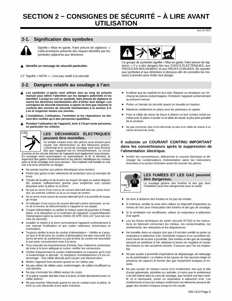
Signifie « Mise en garde. Faire preuve de vigilance. »Cette procédure présente des risques identifiés par lessymboles adjacents aux directives.
� Identifie un message de sécurité particulier.
� Signifie « NOTA » ; n’est pas relatif à la sécurité.
Ce groupe de symboles signifie « Mise en garde. Faire preuve de vigi-lance. » Il y a des dangers liés aux CHOCS ÉLECTRIQUES, auxPIÈCES EN MOUVEMENT et aux PIÈCES CHAUDES. Se reporteraux symboles et aux directives ci-dessous afin de connaître les me-sures à prendre pour éviter tout danger.
2-2. Dangers relatifs au soudage à l’arc
� Les symboles ci-après sont utilisés tout au long du présentmanuel pour attirer l’attention sur les dangers potentiels et lesidentifier. Lorsqu’on voit un symbole, faire preuve de vigilance etsuivre les directives mentionnées afin d’éviter tout danger. Lesconsignes de sécurité énoncées ci-après ne font que résumer lecontenu des normes de sécurité mentionnées à la section 2-4.Lire et respecter toutes ces normes.
� L’installation, l’utilisation, l’entretien et les réparations ne doi-vent être confiés qu’à des personnes qualifiées.
� Pendant l’utilisation de l’appareil, tenir à l’écart toute personne,en particulier les enfants.
LES DÉCHARGES ÉLECTRIQUESpeuvent être mortelles.Un simple contact avec des pièces sous tension peutcauser une électrocution ou des blessures graves.L’électrode et le circuit de soudage sont sous tensiondès que l’appareil est en fonctionnement. Le circuit
d’entrée et les circuits internes de l’appareil sont également sous tension.En soudage semi−automatique ou automatique, le fil, le dévidoir, lelogement des galets d’entraînement et les pièces métalliques en contactavec le fil de soudage sont sous tension. Tout matériel mal installé ou malmis à la terre présente un danger.
� Ne jamais toucher aux pièces électriques sous tension.� Porter des gants et des vêtements de protection secs et exempts de
trous.� S’isoler de la pièce et de la terre au moyen de tapis ou autres disposi-
tifs isolants suffisamment grands pour empêcher tout contactphysique avec la pièce ou la terre.
� Ne pas se servir d’une source de courant alternatif dans les zones humi-des, les endroits confinés ou là où on risque de tomber.
� Ne se servir d’une source de courant alternatif QUE si le procédé de souda-ge l’exige.
� Si l’utilisation d’une source de courant alternatif s’avère nécessaire, se ser-vir de la fonction de télécommande si l’appareil en est équipé.
� Couper l’alimentation ou arrêter le moteur avant de procéder à l’instal-lation, à la réparation ou à l’entretien de l’appareil. Couper/étiqueterl’alimentation selon la norme OSHA 29 CFR 1910.147 (voir les nor-mes de sécurité).
� Installer et mettre à la terre correctement l’appareil conformément àson manuel d’utilisation et aux codes nationaux, provinciaux etmunicipaux.
� Toujours vérifier la terre du cordon d’alimentation − Vérifier et s’assu-rer que le fil de terre du cordon d’alimentation est bien raccordé à laborne de terre du sectionneur ou que la fiche du cordon est raccordéeà une prise correctement mise à la terre.
� Pour exécuter les branchements d’entrée, fixer d’abord le conducteurde mise à la terre adéquat et contre−vérifier les connexions.
� Vérifier fréquemment le cordon d’alimentation et s’assurer qu’il n’estni endommagé ni dénudé ; le remplacer immédiatement s’il est en-dommagé − tout câble dénudé peut causer une électrocution.
� Mettre l’appareil hors tension quand on ne l’utilise pas.� Ne pas utiliser de câbles usés, endommagés, de calibre insuffisant ou
mal épissés.� Ne pas s’enrouler les câbles autour du corps.� Si la pièce soudée doit être mise à la terre, le faire directement avec un
câble distinct.� Ne pas toucher l’électrode quand on est en contact avec la pièce, la
terre ou une électrode d’une autre machine.
� N’utiliser que du matériel en bon état. Réparer ou remplacer sur−le−champ les pièces endommagées. Entretenir l’appareil conformémentau présent manuel.
� Porter un harnais de sécurité quand on travaille en hauteur.
� Maintenir solidement en place tous les panneaux et capots.
� Fixer le câble de retour de façon à obtenir un bon contact métal surmétal avec la pièce à souder ou la table de travail, le plus près possiblede la soudure.
� Ne pas connecter plus d’une électrode ou plus d’un câble de masse à unmême terminal de sortie.
Il subsiste un COURANT CONTINU IMPORTANTdans les convertisseurs après la suppression del’alimentation électrique.� Arrêter les convertisseurs, débrancher le courant électrique et dé-
charger les condensateurs d’alimentation selon les instructionsénoncées à la section Entretien avant de toucher les pièces.
Le soudage génère des fumées et des gaz dontl’inhalation peut être dangereuse pour la santé.
LES FUMÉES ET LES GAZ peuventêtre dangereux.
� Se tenir à distance des fumées et ne pas les inhaler.
� À l’intérieur, ventiler la zone et/ou utiliser un dispositif d’aspiration auniveau de l’arc pour l’évacuation des fumées et des gaz de soudage.
� Si la ventilation est insuffisante, utiliser un respirateur à adductiond’air agréé.
� Lire les fiches techniques de santé−sécurité (FTSS) et les instruc-tions du fabricant concernant les métaux, les consommables, lesrevêtements, les nettoyants et les dégraisseurs.
� Ne travailler dans un espace clos que s’il est bien ventilé ou porter unrespirateur à adduction d’air. Demander toujours à un surveillant dû-ment formé de se tenir à proximité. Des fumées et des gaz de soudagepeuvent se substituer à l’air, abaisser la teneur en oxygène et causerdes lésions ou des accidents mortels. S’assurer que l’air est respira-ble.
� Ne pas souder à proximité d’opérations de dégraissage, de nettoyageou de pulvérisation. La chaleur et les rayons de l’arc peuvent réagir enprésence de vapeurs et former des gaz hautement toxiques et irri-tants.
� Ne pas souder de métaux munis d’un revêtement, tels que la tôled’acier galvanisée, plombée ou cadmiée, à moins que le revêtementn’ait été enlevé dans la zone de soudage, que l’endroit soit bien venti-lé, et si nécessaire, porter un respirateur à adduction d’air. Lesrevêtements et tous les métaux renfermant ces éléments peuvent dé-gager des fumées toxiques lorsqu’on les soude.
OM-1213 Page 6
Le rayonnement de l’arc génère des rayons visibles etinvisibles intenses (ultraviolets et infrarouges) suscep-tibles de causer des brûlures oculaires et cutanées.Des étincelles sont projetées pendant le soudage.
LES RAYONS DE L’ARC peuvent cau-ser des brûlures oculaires et cuta-nées.
� Porter un masque de soudage muni d’un filtre de la nuance adéquatepour se protéger le visage et les yeux pendant le soudage ou pour re-garder (voir les normes de sécurité ANSI Z49.1 et Z87.1).
� Porter des lunettes de sécurité à écrans latéraux sous le masque.� Utiliser des écrans ou des barrières pour protéger les tiers de l’éclat
éblouissant ou aveuglant de l’arc ; leur demander de ne pas regarderl’arc.
� Porter des vêtements de protection en matière durable et ignifuge(cuir ou laine) et des chaussures de sécurité.
Le soudage effectué sur des récipients fermés tels quedes réservoirs, des fûts ou des conduites peut causerleur éclatement. Des étincelles peuvent être projetéesde l’arc de soudure. La projection d’étincelles, les
pièces chaudes et les équipements chauds peuvent causer desincendies et des brûlures. Le contact accidentel de l’électrode avec toutobjet métallique peut causer des étincelles, une explosion, un surchauf-fement ou un incendie. Avant de commencer le soudage, vérifier ets’assurer que l’endroit ne présente pas de danger.
LE SOUDAGE peut causer un incen-die ou une explosion.
� Se protéger et protéger les tiers de la projection d’étincelles et de mé-tal chaud.
� Ne pas souder à un endroit où des étincelles peuvent tomber sur dessubstances inflammables.
� Placer toutes les substances inflammables à une distance de 10,7 mde l’arc de soudage. En cas d’impossibilité, les recouvrir soigneuse-ment avec des protections agréées.
� Des étincelles et des matières en fusion peuvent facilement passermême par des fissures et des ouvertures de petites dimensions.
� Surveiller tout déclenchement d’incendie et tenir un extincteur à proxi-mité.
� Le soudage effectué sur un plafond, un plancher, une paroi ou unecloison peut déclencher un incendie de l’autre côté.
� Ne pas souder des récipients fermés tels que des réservoirs, des fûtsou des conduites, à moins qu’ils n’aient été préparés conformément àl’AWS F4.1 (voir les normes de sécurité).
� Brancher le câble sur la pièce le plus près possible de la zone de sou-dage pour éviter que le courant ne circule sur une longue distance, pardes chemins inconnus, et ne cause des risques d’électrocution et d’in-cendie.
� Ne pas utiliser le poste de soudage pour dégeler des conduites ge-lées.
� En cas de non utilisation, enlever la baguette d’électrode du porte−électrode ou couper le fil au raz du tube−contact.
� Porter des vêtements de protection exempts d’huile tels que desgants en cuir, une chemise en tissu épais, des pantalons sans revers,des chaussures montantes et un masque.
� Avant de souder, retirer tout produit combustible de ses poches, telqu’un briquet au butane ou des allumettes.
LES PARTICULES PROJETÉES peu-vent blesser les yeux.
� Le soudage, le burinage, le passage de la pièce àla brosse métallique et le meulage provoquentl’émission d’étincelles et de particules métalli-
ques. Pendant leur refroidissement, les soudures risquent de projeter dulaitier.� Porter des lunettes de sécurité à écrans latéraux agréés, même sous le
masque de soudage.
LES ACCUMULATIONS DE GAZ peu-vent causer des blessures ou mêmela mort.
� Couper l’alimentation en gaz protecteur en cas denon utilisation.
� Veiller toujours à bien ventiler les espaces confinés ou porter un respira-teur à adduction d’air agréé.
LES PIÈCES CHAUDES peuvent cau-ser des brûlures graves.
� Ne pas toucher les pièces chaudes à main nue.� Prévoir une période de refroidissement avant
d’utiliser le pistolet ou la torche.
LES CHAMPS MAGNÉTIQUES peuventperturber le fonctionnement des stimu-lateurs cardiaques.
� Les personnes qui portent un stimulateur cardiaquedoivent se tenir à distance.
� Ils doivent consulter leur médecin avant de s’appro-cher d’un lieu où on exécute des opérations de sou-dage à l’arc, de gougeage ou de soudage par points.
LE BRUIT peut affecter l’ouïe.
Le bruit de certains processus et équipements peutaffecter l’ouïe.
� Porter des protecteurs d’oreille agréés si le niveausonore est trop élevé.
Les bouteilles de gaz protecteur contiennent du gazsous haute pression. Toute bouteille endommagéepeut exploser. Comme les bouteilles de gaz fontnormalement partie du procédé de soudage, les
manipuler avec précaution.
Les BOUTEILLES endommagéespeuvent exploser.
� Protéger les bouteilles de gaz comprimé de la chaleur excessive, deschocs mécaniques, du laitier, des flammes nues, des étincelles et desarcs.
� Placer les bouteilles debout en les fixant dans un support stationnaireou dans un porte−bouteilles pour les empêcher de tomber ou de serenverser.
� Tenir les bouteilles éloignées des circuits de soudage ou autres cir-cuits électriques.
� Ne jamais poser une torche de soudage sur une bouteille de gaz.� Ne jamais mettre une électrode de soudage en contact avec une bou-
teille de gaz.� Ne jamais souder une bouteille contenant du gaz sous pression − elle
risquerait d’exploser.� N’utiliser que les bouteilles de gaz protecteur, régulateurs, tuyaux et
raccords adéquats pour l’application envisagée ; les maintenir en bonétat, ainsi que les pièces connexes.
� Détourner la tête lorsqu’on ouvre la soupape d’une bouteille.� Laisser le capuchon protecteur sur la soupape, sauf en cas d’utilisa-
tion ou de branchement de la bouteille� Lire et suivre les instructions concernant les bouteilles de gaz compri-
mé, les équipements associés et les publications P−1 de la CGA,mentionnées dans les normes de sécurité.
OM-1213 Page 7
2-3. Autres symboles relatifs à l’installation, au fonctionnement et à l’entretien del’appareil.
Risque D’INCENDIE OU D’EXPLO-SION
� Ne pas placer l’appareil sur une surface inflam-mable, ni au−dessus ou à proximité d’elle.
� Ne pas installer l’appareil à proximité de produits inflammables.� Ne pas surcharger l’installation électrique − s’assurer que l’alimen-
tation est correctement dimensionnée et protégée avant de mettrel’appareil en service.
LA CHUTE DE L’APPAREIL peutblesser.
� N’utiliser que l’anneau de levage pour lever l’ap-pareil. NE PAS utiliser le chariot, les bouteilles degaz ou tout autre accessoire.
� Utiliser un engin de capacité adéquate pour leverl’appareil.
� Si on utilise un chariot élévateur pour déplacer l’unité, s’assurer queles fourches sont suffisamment longues pour dépasser du côté op-posé de l’appareil.
L’EMPLOI EXCESSIF peut FAIRESURCHAUFFER L’ÉQUIPEMENT.
� Prévoir une période de refroidissement ; respec-ter le cycle opératoire nominal.
� Réduire le courant ou le cycle opératoire avant dereprendre le soudage.
� Ne pas obstruer les orifices ou filtrer l’alimentation en air du poste.
LES CHARGES ÉLECTROSTATI-QUES peuvent endommager les cir-cuits imprimés.
� Mettre un bracelet antistatique AVANT de mani-puler des cartes ou des pièces.
� Utiliser des pochettes et des boîtes antistatiquespour stocker, déplacer ou expédier des cartes decircuits imprimés.
LES PIÈCES MOBILES peuvent cau-ser des blessures.
� Se tenir à l’écart des pièces mobiles.� Se tenir à l’écart des points de coincement tels
que les dévidoirs.
LES FILS DE SOUDAGE peuvent cau-ser des blessures.
� Ne pas appuyer sur la gâchette avant d’en avoirreçu l’instruction.
� Ne pas diriger le pistolet vers soi, vers d’autrespersonnes ou vers toute pièce mécanique en en-gageant le fil de soudage.
LES ORGANES MOBILES peuventcauser des blessures.
� Se tenir à l’écart des organes mobiles comme lesventilateurs.
� Maintenir fermés et bien fixés les portes,panneaux, recouvrements et dispositifs deprotection.
LE RAYONNEMENT HAUTE FRÉ-QUENCE (H. F.) risque de causer desinterférences.
� Le rayonnement haute fréquence peut causerdes interférences avec les équipements de radio-navigation et de communication, les services desécurité et les ordinateurs.
� Ne demander qu’à des personnes qualifiées familiarisées avec leséquipements électroniques de faire fonctionner l’installation.
� L’utilisateur est tenu de faire corriger rapidement par un électricienqualifié les interférences causées par l’installation.
� Si la Federal Communications Commission signale des interféren-ces, arrêter immédiatement l’appareil.
� Faire régulièrement contrôler et entretenir l’installation.� Maintenir soigneusement fermés les panneaux et les portes des sour-
ces de haute fréquence, maintenir le jeu d’éclatement au réglageadéquat et utiliser une terre et un blindage pour réduire les interféren-ces éventuelles.
LE SOUDAGE À L’ARC peut causerdes interférences.
� L’énergie électromagnétique peut causer desinterférences avec l’équipement électroniquesensible tel que les ordinateurs et l’équipementcommandé par ordinateur tel que les robots.
� Veiller à ce que tout l’équipement de la zone de soudage soit compati-ble au point de vue électromagnétique.
� Pour réduire la possibilité d’interférence, maintenir les câbles de sou-dage aussi courts que possible, les grouper, et les poser aussi basque possible (par ex. : à terre).
� Veiller à souder à une distance de 100 mètres de tout équipementélectronique sensible.
� Veiller à ce que le poste de soudage soit posé et mis à la terre confor-mément au présent manuel.
� En cas d’interférences après exécution des directives précédentes, ilincombe à l’utilisateur de prendre des mesures supplémentaires tel-les que le déplacement du poste, l’utilisation de câbles blindés,l’utilisation de filtres de ligne ou la pose de protecteurs dans la zone detravail.
LES CHAMPS MAGNÉTIQUES peuventaffecter les stimulateurs cardiaques.
� Porteurs de stimulateur cardiaque, restez à dis-tance.
� Les porteurs d’un stimulateur cardiaque doiventd’abord consulter leur médecin avant de s’appro-cher des opérations de soudage à l’arc, de gou-geage ou de soudage par points.

OM-1213 Page 8
2-4. Principales normes de sécurité
Safety in Welding, Cutting, and Allied Processes, norme ANSI Z49.1,de l’American Welding Society, 550 N.W. LeJeune Rd, Miami FL 33126(téléphone : (305) 443−9353, site Web : www.aws.org).
Recommended Safe Practices for the Preparation for Welding and Cut-ting of Containers and Piping, norme American Welding Society AWSF4.1, de l’American Welding Society, 550 N.W. LeJeune Rd, Miami, FL33126 (téléphone : (305) 443−9353, site Web : www.aws.org).
National Electrical Code, norme NFPA 70, de la National Fire ProtectionAssociation, P.O. Box 9101, 1 Battery March Park, Quincy, MA02269−9101 (téléphone : (617) 770−3000, sites Web : www.nfpa.org etwww.sparky.org).
Safe Handling of Compressed Gases in Cylinders, brochure CGA P−1,de la Compressed Gas Association, 1735 Jefferson Davis Highway,Suite 1004, Arlington, VA 22202−4102 (téléphone : (703) 412−0900,site Web : www.cganet.com).
Code for Safety in Welding and Cutting, norme CSA W117.2, de la Ca-nadian Standards Association, Standards Sales, 178 boulevard
Rexdale, Rexdale (Ontario) Canada M9W 1R3 (téléphone : (800)463−6727 ou à Toronto : (416) 747−4044, site Web : www.csa−interna-tional.org).
Practice For Occupational And Educational Eye And Face Protection,norme ANSI Z87.1, de l’American National Standards Institute, 11 West42nd Street, New York, NY 10036−8002 (téléphone : (212) 642−4900,site Web : www.ansi.org).
Standard for Fire Prevention During Welding, Cutting, and Other HotWork, norme NFPA 51B, de la National Fire Protection Association,P.O. Box 9101, 1 Battery March Park, Quincy, MA 02269−9101 (télé-phone : (617) 770−3000, site Web : www.nfpa.org et www.sparky.org).
OSHA, Occupational Safety and Health Standards for General Indus-try, Title 29, Code of Federal Regulations (CFR), Part 1910, Subpart Q,and Part 1926, Subpart J, de l’U.S. Government Printing Office, Super-intendent of Documents, P.O. Box 371954, Pittsburgh, PA 15250 (il y a10 bureaux régionaux − Téléphone pour la Région 5, Chicago : (312)353−2220, site Web : www.osha.gov).
2-5. Information sur les champs électromagnétiques
Données sur le soudage électrique et les effets des champs magnéti-ques basse fréquence sur l’organisme
En parcourant les câbles de soudage, le courant crée des champs élec-tromagnétiques. Les effets potentiels de tels champs restentpréoccupants. Cependant, après avoir examiné plus de 500 études quiont été faites pendant une période de recherche de 17 ans, un comitéde spécialistes du National Research Council a conclu : « L’accumula-tion de preuves n’a pas démontré que l’exposition aux champsmagnétiques et aux champs électriques à haute fréquence constitue unrisque pour la santé humaine ». Toutefois, les études et l’examen despreuves se poursuivent. En attendant les conclusions finales de la re-cherche, il serait souhaitable de réduire l’exposition aux champsélectromagnétiques pendant le soudage ou le coupage.
Afin de réduire les champs électromagnétiques en milieu de travail, res-pecter les consignes suivantes :
1. Garder les câbles ensemble en les torsadant ou en les fixant avec duruban adhésif.
2. Mettre tous les câbles du côté opposé à l’opérateur.
3. Ne pas s’enrouler les câbles autour du corps.
4. Garder le poste de soudage et les câbles le plus loin possible de soi.
5. Placer la pince de masse le plus près possible de la zone de soudage.
Consignes relatives aux stimulateurs cardiaques :
Les personnes qui portent un stimulateur cardiaque doivent avant toutconsulter leur médecin. Si ce dernier les déclare aptes, il leur est recom-mandé de respecter les consignes ci-dessus.
OM-1213 Page 9
SECTION 3 − DEFINITIONS
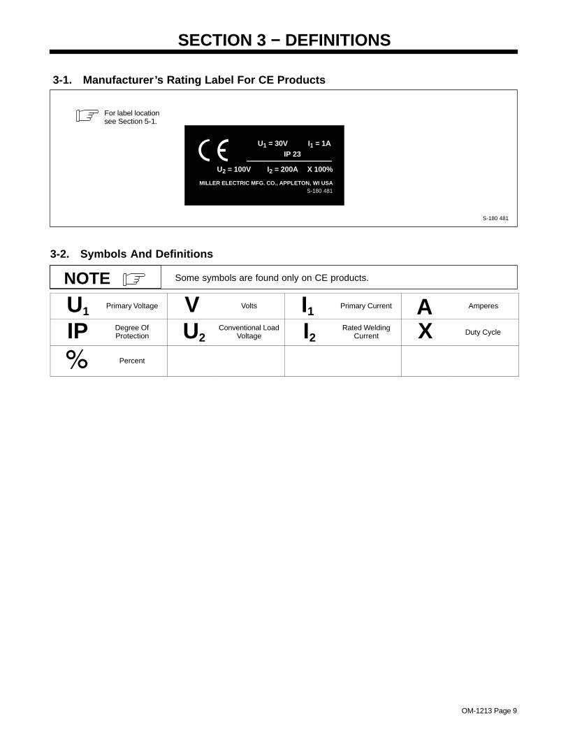
3-1. Manufacturer’s Rating Label For CE Products
S-180 481
For label locationsee Section 5-1.
MILLER ELECTRIC MFG. CO., APPLETON, WI USA
U1 = 30V I1 = 1AIP 23
U2 = 100V I2 = 200A X 100%
S-180 481
3-2. Symbols And Definitions
Some symbols are found only on CE products.NOTE
U1Primary Voltage V Volts I1
Primary Current A Amperes
IP Degree OfProtection U2
Conventional LoadVoltage I2
Rated WeldingCurrent X Duty Cycle
Percent
OM-1213 Page 10
SECTION 4 − INSTALLATION
4-1. Specifications
Wire DiameterRange
ApproximateWire Feed
Range
CoolingMethod
MaximumSpool Size
WeldCircuitRating
IP Rating OverallDimensions Weight
.025 Thru 1/16 in(0.6 Thru 1.6 mm)
Aluminum Wire
.025 Thru .045 in(0.6 Thru 1.1 mm)
Hard Or Cored Wire
70 To 875 ipm(1.7 To 22.2
mpm)Air Cooled
4 in (102 mm)Diameter
100 Volts,200 Amperes,
100% DutyCycle Using
ArgonShielding Gas
IP 23
Length: 15-3/8 in(390 mm)
Width: 2-1/2 in(64 mm)
Height: 10-3/4 in(273 mm)
2.9 lb(1.3 kg) Gun
Only
15A Model:9 lb (4.1 kg)
Gun With Cable30A Model:
14 lb (6.4 kg)Gun With Cable
Use weld control or welding power source Owner’s Manual during gun installation.If contact tip, liner, and drive roll groove are not correct for wire size and type, seeSection 6 to change parts as needed. See Parts List for other available contacttips.
NOTE
4-2. Removing Top Cover
150 882-G
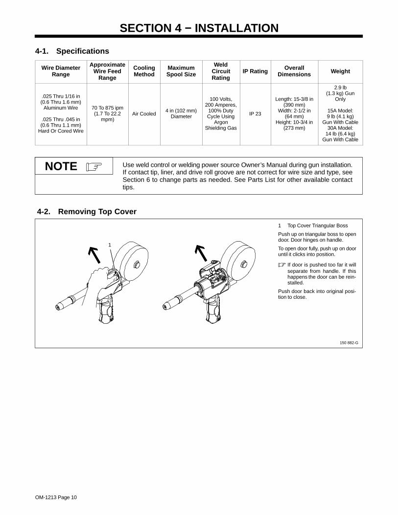
1 Top Cover Triangular Boss
Push up on triangular boss to opendoor. Door hinges on handle.
To open door fully, push up on dooruntil it clicks into position.
� If door is pushed too far it willseparate from handle. If thishappens the door can be rein-stalled.
Push door back into original posi-tion to close.
1
OM-1213 Page 11
4-3. Installing Wire Spool And Threading Welding Wire
150 436-F
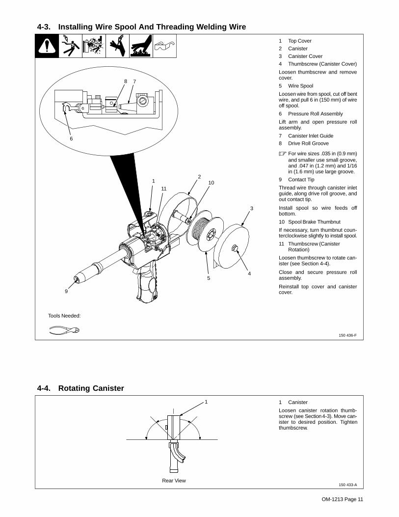
1 Top Cover
2 Canister
3 Canister Cover
4 Thumbscrew (Canister Cover)
Loosen thumbscrew and removecover.
5 Wire Spool
Loosen wire from spool, cut off bentwire, and pull 6 in (150 mm) of wireoff spool.
6 Pressure Roll Assembly
Lift arm and open pressure rollassembly.
7 Canister Inlet Guide8 Drive Roll Groove
� For wire sizes .035 in (0.9 mm)and smaller use small groove,and .047 in (1.2 mm) and 1/16in (1.6 mm) use large groove.
9 Contact Tip
Thread wire through canister inletguide, along drive roll groove, andout contact tip.
Install spool so wire feeds offbottom.
10 Spool Brake Thumbnut
If necessary, turn thumbnut coun-terclockwise slightly to install spool.
11 Thumbscrew (CanisterRotation)
Loosen thumbscrew to rotate can-ister (see Section 4-4).
Close and secure pressure rollassembly.
Reinstall top cover and canistercover.
Tools Needed:
9
12
10
3
45
6
78
11
4-4. Rotating Canister
150 433-A
1 Canister
Loosen canister rotation thumb-screw (see Section 4-3). Move can-ister to desired position. Tightenthumbscrew.
1
Rear View
OM-1213 Page 12
4-5. Connecting To 24 Volt Weld Control
150 917-G
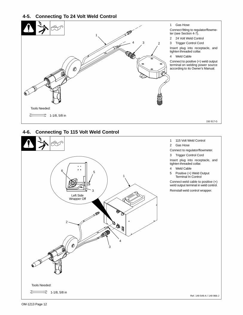
1 Gas Hose
Connect fitting to regulator/flowme-ter (see Section 4-7).
2 24 Volt Weld Control
3 Trigger Control Cord
Insert plug into receptacle, andtighten threaded collar.
4 Weld Cable
Connect to positive (+) weld outputterminal on welding power sourceaccording to its Owner’s Manual.
Tools Needed:
1-1/8, 5/8 in
1
234
4-6. Connecting To 115 Volt Weld Control
Ref. 149 549-A / 149 966-J
1 115 Volt Weld Control
2 Gas Hose
Connect to regulator/flowmeter.
3 Trigger Control Cord
Insert plug into receptacle, andtighten threaded collar.
4 Weld Cable
5 Positive (+) Weld OutputTerminal In Control
Connect weld cable to positive (+)weld output terminal in weld control.
Reinstall weld control wrapper.
Left SideWrapper Off
56
1
2
3
4
3
Tools Needed:
1-1/8, 5/8 in

OM-1213 Page 13
4-7. Installing Gas Supply
ssb3.1* 5/94 − 158 697-A
Obtain gas cylinder and chain torunning gear, wall, or other station-ary support so cylinder cannot falland break off valve.
1 Cap
2 Cylinder Valve
Remove cap, stand to side of valve,and open valve slightly. Gas flowblows dust and dirt from valve.Close valve.
3 Cylinder
4 Regulator/Flowmeter
Install so face is vertical.
5 Gas Hose Connection
Fitting has 5/8-18 right-handthreads.
6 Flow Adjust
Typical flow rate is 20 cfh (cubic feetper hour). Check wire manufactur-er’s recommended flow rate.
Make sure flow adjust is closedwhen opening cylinder to avoiddamage to the flowmeter.
7 CO2 Adapter
8 O-Ring
Install adapter with O-ring betweenregulator/flowmeter and CO2cylinder.
Tools Needed:
1-1/8, 5/8 in
CO2 Gas
7 8
3
1
2
4
5
6
1
2
3
Argon Gas
OR
OM-1213 Page 14
4-8. Adjusting Drive Roll And Spool Brake Pressure
Ref. 151 112-F / 147 741-F
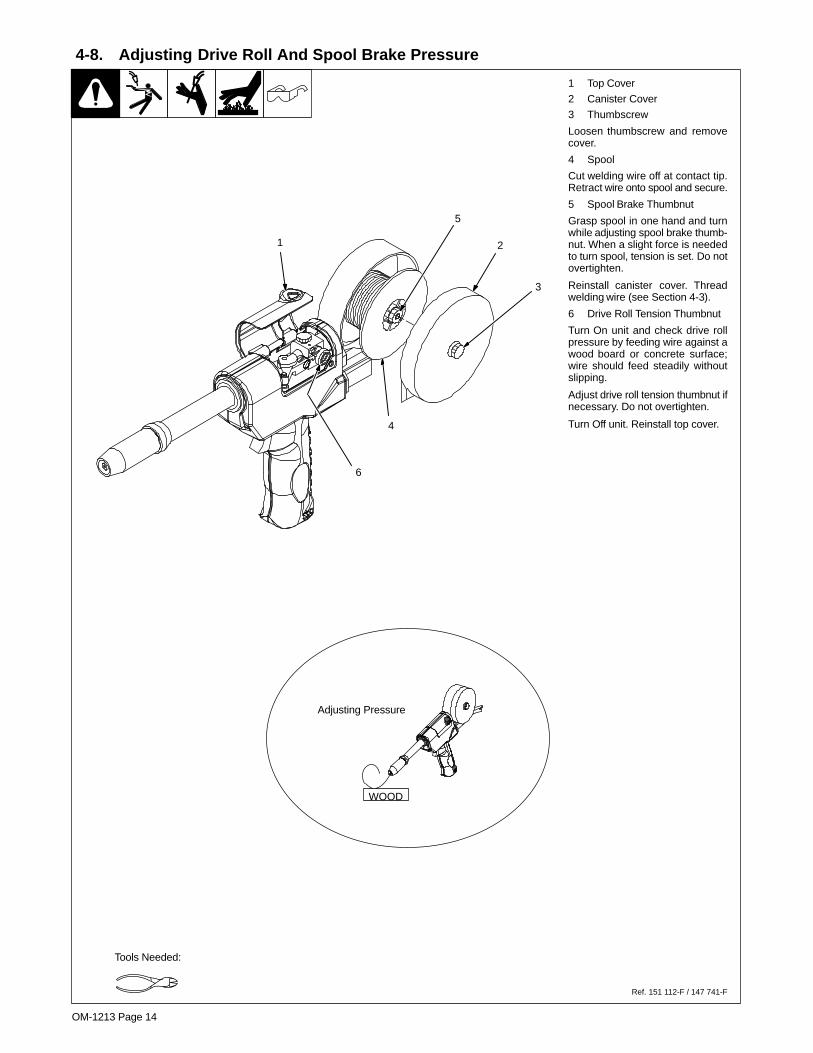
1 Top Cover
2 Canister Cover
3 Thumbscrew
Loosen thumbscrew and removecover.
4 Spool
Cut welding wire off at contact tip.Retract wire onto spool and secure.
5 Spool Brake Thumbnut
Grasp spool in one hand and turnwhile adjusting spool brake thumb-nut. When a slight force is neededto turn spool, tension is set. Do notovertighten.
Reinstall canister cover. Threadwelding wire (see Section 4-3).
6 Drive Roll Tension Thumbnut
Turn On unit and check drive rollpressure by feeding wire against awood board or concrete surface;wire should feed steadily withoutslipping.
Adjust drive roll tension thumbnut ifnecessary. Do not overtighten.
Turn Off unit. Reinstall top cover.
Tools Needed:
WOOD
Adjusting Pressure
1 2
5
3
4
6
OM-1213 Page 15
SECTION 5 − OPERATION
5-1. Controls
Ref. 147 741-F
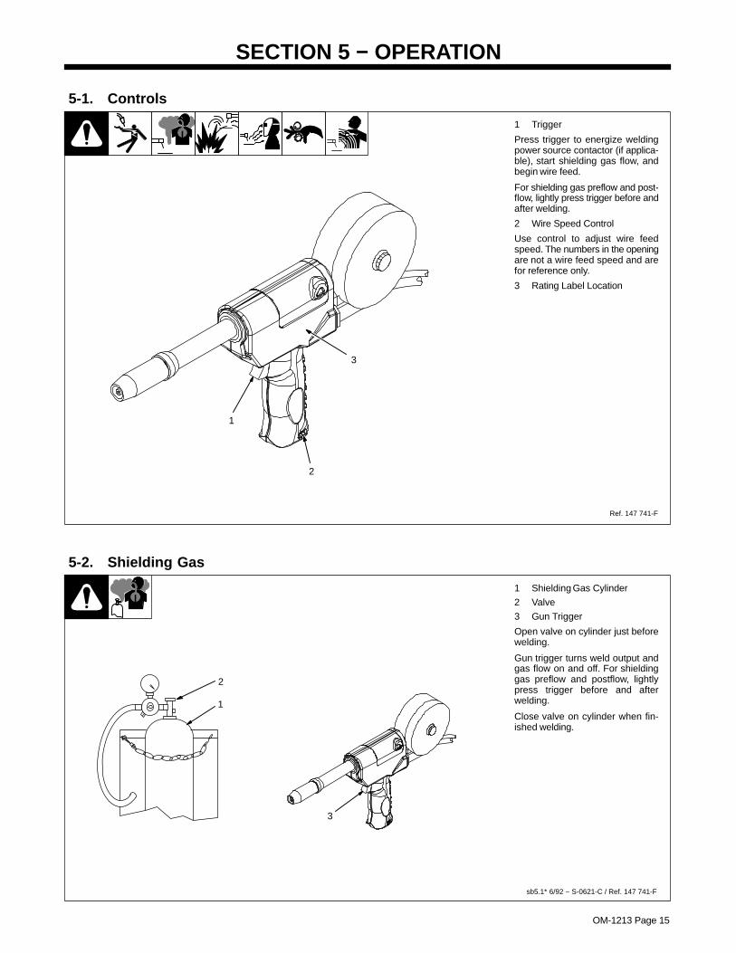
1 Trigger
Press trigger to energize weldingpower source contactor (if applica-ble), start shielding gas flow, andbegin wire feed.
For shielding gas preflow and post-flow, lightly press trigger before andafter welding.
2 Wire Speed Control
Use control to adjust wire feedspeed. The numbers in the openingare not a wire feed speed and arefor reference only.
3 Rating Label Location
1
2
3
5-2. Shielding Gas
sb5.1* 6/92 − S-0621-C / Ref. 147 741-F
1 Shielding Gas Cylinder
2 Valve
3 Gun Trigger
Open valve on cylinder just beforewelding.
Gun trigger turns weld output andgas flow on and off. For shieldinggas preflow and postflow, lightlypress trigger before and afterwelding.
Close valve on cylinder when fin-ished welding.
1
2
3
OM-1213 Page 16
SECTION 6 − MAINTENANCE & TROUBLESHOOTING
6-1. Routine Maintenance
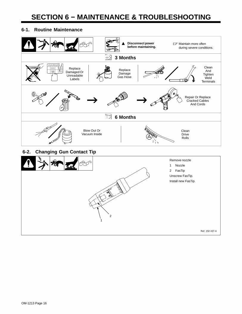
� Disconnect power before maintaining.
� Maintain more oftenduring severe conditions.
3 Months
ReplaceDamaged OrUnreadable
Labels
ReplaceDamage
Gas Hose
CleanAnd
TightenWeld
Terminals
Repair Or ReplaceCracked Cables
And Cords
6 Months
Blow Out OrVacuum Inside
CleanDriveRolls
6-2. Changing Gun Contact Tip
Ref. 150 437-A
21
Remove nozzle
1 Nozzle
2 FasTip
Unscrew FasTip.
Install new FasTip.
OM-1213 Page 17
6-3. Replacing Head Tube Liner
Ref. 803 551-C
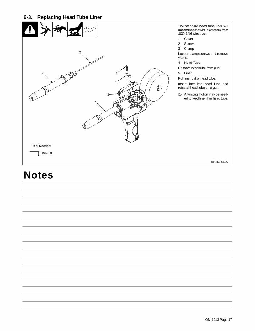
The standard head tube liner willaccommodate wire diameters from.030-1/16 wire size.
1 Cover
2 Screw
3 Clamp
Loosen clamp screws and removeclamp.
4 Head Tube
Remove head tube from gun.
5 Liner
Pull liner out of head tube.
Insert liner into head tube andreinstall head tube onto gun.
� A twisting motion may be need-ed to feed liner thru head tube.
4
5
5/32 in
1
2
3
4
Tool Needed:
Notes
OM-1213 Page 18
6-4. Gun Drive Assembly Maintenance
Ref. 149 967-H / Ref. 800 945-A
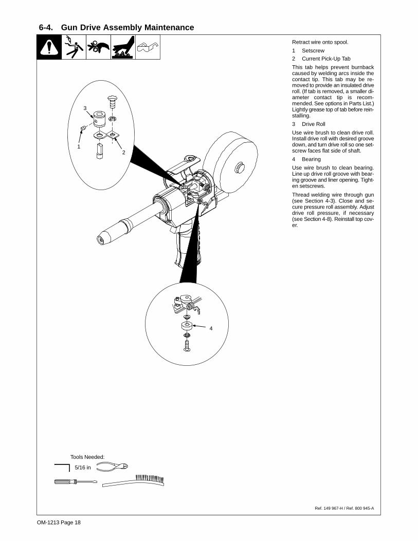
Retract wire onto spool.
1 Setscrew
2 Current Pick-Up Tab
This tab helps prevent burnbackcaused by welding arcs inside thecontact tip. This tab may be re-moved to provide an insulated driveroll. (If tab is removed, a smaller di-ameter contact tip is recom-mended. See options in Parts List.)Lightly grease top of tab before rein-stalling.
3 Drive Roll
Use wire brush to clean drive roll.Install drive roll with desired groovedown, and turn drive roll so one set-screw faces flat side of shaft.
4 Bearing
Use wire brush to clean bearing.Line up drive roll groove with bear-ing groove and liner opening. Tight-en setscrews.
Thread welding wire through gun(see Section 4-3). Close and se-cure pressure roll assembly. Adjustdrive roll pressure, if necessary(see Section 4-8). Reinstall top cov-er.
Tools Needed:
5/16 in
3
12
4
OM-1213 Page 19
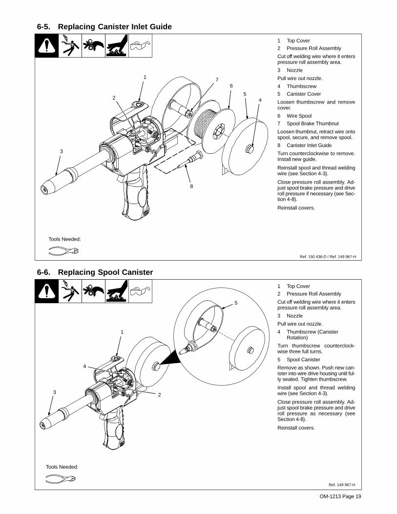
6-5. Replacing Canister Inlet Guide
Ref. 150 436-D / Ref. 149 967-H
1 Top Cover
2 Pressure Roll Assembly
Cut off welding wire where it enterspressure roll assembly area.
3 Nozzle
Pull wire out nozzle.
4 Thumbscrew
5 Canister Cover
Loosen thumbscrew and removecover.
6 Wire Spool
7 Spool Brake Thumbnut
Loosen thumbnut, retract wire ontospool, secure, and remove spool.
8 Canister Inlet Guide
Turn counterclockwise to remove.Install new guide.
Reinstall spool and thread weldingwire (see Section 4-3).
Close pressure roll assembly. Ad-just spool brake pressure and driveroll pressure if necessary (see Sec-tion 4-8).
Reinstall covers.
Tools Needed:
1
2 45
67
8
3
6-6. Replacing Spool Canister
Ref. 149 967-H
1 Top Cover
2 Pressure Roll Assembly
Cut off welding wire where it enterspressure roll assembly area.
3 Nozzle
Pull wire out nozzle.
4 Thumbscrew (CanisterRotation)
Turn thumbscrew counterclock-wise three full turns.
5 Spool Canister
Remove as shown. Push new can-ister into wire drive housing until ful-ly seated. Tighten thumbscrew.
Install spool and thread weldingwire (see Section 4-3).
Close pressure roll assembly. Ad-just spool brake pressure and driveroll pressure as necessary (seeSection 4-8).
Reinstall covers.
Tools Needed:
1
3
5
2
4
OM-1213 Page 20
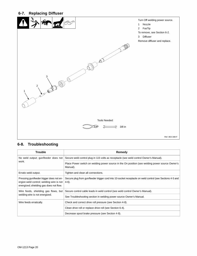
6-7. Replacing Diffuser
Ref. 803 348-F
Turn Off welding power source.
1 Nozzle
2 FasTip
To remove, see Section 6-2.
3 Diffuser
Remove diffuser and replace.
Tools Needed:
3/8 in
1
2
3
6-8. Troubleshooting
Trouble Remedy
No weld output; gun/feeder does notwork.
Secure weld control plug in 115 volts ac receptacle (see weld control Owner’s Manual).work.
Place Power switch on welding power source in the On position (see welding power source Owner’sManual).
Erratic weld output. Tighten and clean all connections.
Pressing gun/feeder trigger does not en-ergize weld control; welding wire is notenergized; shielding gas does not flow.
Secure plug from gun/feeder trigger cord into 10-socket receptacle on weld control (see Sections 4-5 and4-6).
Wire feeds, shielding gas flows, butwelding wire is not energized.
Secure control cable leads in weld control (see weld control Owner’s Manual).welding wire is not energized.
See Troubleshooting section in welding power source Owner’s Manual.
Wire feeds erratically. Check and correct drive roll pressure (see Section 4-8).
Clean drive roll or replace drive roll (see Section 6-4).
Decrease spool brake pressure (see Section 4-8).
OM-1213 Page 21
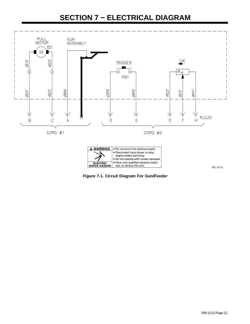
SECTION 7 − ELECTRICAL DIAGRAM
195 712-A
Figure 7-1. Circuit Diagram For Gun/Feeder
OM-1213 Page 22
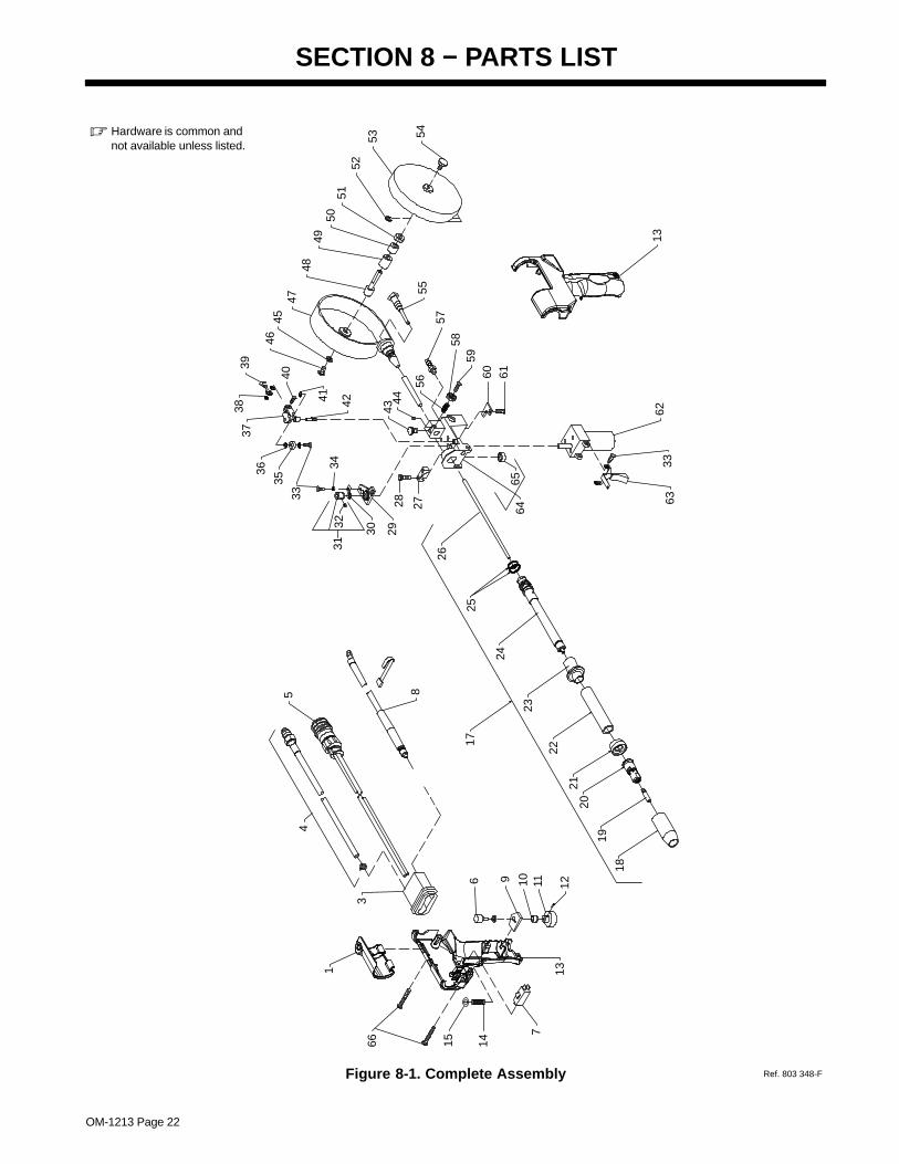
SECTION 8 − PARTS LIST
Figure 8-1. Complete Assembly Ref. 803 348-F
� Hardware is common andnot available unless listed.
3
1
45 8
6 9 10 11 1213
7
1415
6333
62
545352
5150
4948
4745
46
41
40
3938 42
3736
35
33
34
30 29
3231
28 2755
4344
57
56
5859
60 6165
64
66
13
2517
24
2120
18
19
22
23
26

OM-1213 Page 23
Quantity
DescriptionPartNo.
Dia.Mkgs.
ItemNo. 30A
Figure 8-1. Complete Assembly
Model15A
1 214 745 COVER (included with item 13) 1 1. . . . . . . . . . . . . . . . . . . . . . . . . . . . . . . . . . . . . . . . . . . . . . . . . . 2 Deleted. . . . . . . . . . . . . . . . . . . . . . . . . . . . . . . . . . . . . . . . . . . . . . . . . . . . . . . . . . . . . . . . . . . . . . . . . . . . . . . . . . . . . 3 133 362 STRAIN RELIEF, cable 1 1. . . . . . . . . . . . . . . . . . . . . . . . . . . . . . . . . . . . . . . . . . . . . . . . . . . . . . . . . 4 210 417 HOSE, gas in 1. . . . . . . . . . . . . . . . . . . . . . . . . . . . . . . . . . . . . . . . . . . . . . . . . . . . . . . . . . . . . . 4 182 824 HOSE, gas in 1. . . . . . . . . . . . . . . . . . . . . . . . . . . . . . . . . . . . . . . . . . . . . . . . . . . . . . . . . . . . . . . . . . . . . 5 210 418 CABLE, control 15 ft (includes) 1. . . . . . . . . . . . . . . . . . . . . . . . . . . . . . . . . . . . . . . . . . . . . . . 5 204 605 CABLE, control 30 ft (includes) 1. . . . . . . . . . . . . . . . . . . . . . . . . . . . . . . . . . . . . . . . . . . . . . . . . . . . . . 6 R4 200 096 POTENTIOMETER, C sltd sft 1/T .5W 10K ohm 1 1. . . . . . . . . . . . . . . . . . . . . . . . . . . . . . . . 7 PB1 000 369 SWITCH, lim 10A 125/250VAC DPST plgr 1 1. . . . . . . . . . . . . . . . . . . . . . . . . . . . . . . . . . . .
190 294 CONN, circ MS/CPC 10 pin 1 1. . . . . . . . . . . . . . . . . . . . . . . . . . . . . . . . . . . . . . . . . . . . . . . . . . . . . . . . . 143 922 CONN, circ CPC clamp str rlf 1 1. . . . . . . . . . . . . . . . . . . . . . . . . . . . . . . . . . . . . . . . . . . . . . . . . . . . . . . .
8 210 416 CABLE, power 1. . . . . . . . . . . . . . . . . . . . . . . . . . . . . . . . . . . . . . . . . . . . . . . . . . . . . . . . . . . . . 8 137 479 CABLE, power 1. . . . . . . . . . . . . . . . . . . . . . . . . . . . . . . . . . . . . . . . . . . . . . . . . . . . . . . . . . . . . . . . . . . . 9 144 861 WASHER, anti-turn 1 1. . . . . . . . . . . . . . . . . . . . . . . . . . . . . . . . . . . . . . . . . . . . . . . . . . . . . . . . . . . . .
10 135 127 LOCK, shaft pot .250-32 x .125dia shaft 1 1. . . . . . . . . . . . . . . . . . . . . . . . . . . . . . . . . . . . . . . . . . . 11 134 856 KNOB, speed control 1-10 .140 shaft x 1.125 OD 1 1. . . . . . . . . . . . . . . . . . . . . . . . . . . . . . . . . . . 12 602 169 SCREW, set stl sch 8-32 x .187 cup pt 1 1. . . . . . . . . . . . . . . . . . . . . . . . . . . . . . . . . . . . . . . . . . . . 13 220 658 CASE, gun lh/rh (molded halves) 1 1. . . . . . . . . . . . . . . . . . . . . . . . . . . . . . . . . . . . . . . . . . . . . . . . . 14 183 884 SPRING, cprsn .240 OD x .026 wire x 1.000 1 1. . . . . . . . . . . . . . . . . . . . . . . . . . . . . . . . . . . . . . . 15 184 101 WASHER, shldr .140 ID x .250 OD 1 1. . . . . . . . . . . . . . . . . . . . . . . . . . . . . . . . . . . . . . . . . . . . . . . 16 Deleted. . . . . . . . . . . . . . . . . . . . . . . . . . . . . . . . . . . . . . . . . . . . . . . . . . . . . . . . . . . . . . . . . . . . . . . . . . . . . . . . . . . . . 17 219 793 BARREL ASSY, air cooled pistol (includes) 1 1. . . . . . . . . . . . . . . . . . . . . . . . . . . . . . . . . . . . . . . . 18 199 613 NOZZLE, brass 5/8 in orifice tapered 1 1. . . . . . . . . . . . . . . . . . . . . . . . . . . . . . . . . . . . . . . . . . . . . . 19 TIP, fastip (See Section 9) 1 1. . . . . . . . . . . . . . . . . . . . . . . . . . . . . . . . . . . . . . . . . . . . . . . . . . . . . . . . . . . . . . . . 20 206 195 DIFFUSER, .281/.312 od fastip 1/8 tip recess 1 1. . . . . . . . . . . . . . . . . . . . . . . . . . . . . . . . . . . . . . 21 198 856 INSULATOR, nozzle 1 1. . . . . . . . . . . . . . . . . . . . . . . . . . . . . . . . . . . . . . . . . . . . . . . . . . . . . . . . . . . . 22 219 794 JACKET, outer insulating 1 1. . . . . . . . . . . . . . . . . . . . . . . . . . . . . . . . . . . . . . . . . . . . . . . . . . . . . . . . 23 219 795 INSULATOR, barrel pistol 1 1. . . . . . . . . . . . . . . . . . . . . . . . . . . . . . . . . . . . . . . . . . . . . . . . . . . . . . . . 24 219 796 HEAD TUBE, air pistol (brazed) 1 1. . . . . . . . . . . . . . . . . . . . . . . . . . . . . . . . . . . . . . . . . . . . . . . . . . 25 134 800 O-RING, .614 ID x .070CS 2 2. . . . . . . . . . . . . . . . . . . . . . . . . . . . . . . . . . . . . . . . . . . . . . . . . . . . . . . 26 212 156 LINER, phos bronze .030-1/16 wire x 7.313 1 1. . . . . . . . . . . . . . . . . . . . . . . . . . . . . . . . . . . . . . . . 27 133 365 CLAMP, head tube 1 1. . . . . . . . . . . . . . . . . . . . . . . . . . . . . . . . . . . . . . . . . . . . . . . . . . . . . . . . . . . . . 28 000 417 SCREW, 10-24 x1.000sochd hex 2 2. . . . . . . . . . . . . . . . . . . . . . . . . . . . . . . . . . . . . . . . . . . . . . . . . 29 162 041 BEARING BLOCK ASSEMBLY 1 1. . . . . . . . . . . . . . . . . . . . . . . . . . . . . . . . . . . . . . . . . . . . . . . . . .
604 638 SCREW, 6-32 x .375sochd hex 3 3. . . . . . . . . . . . . . . . . . . . . . . . . . . . . . . . . . . . . . . . . . . . . . . . . . . . . . 143 480 SCREW, 6-32 x .625sochd hex stl 1 1. . . . . . . . . . . . . . . . . . . . . . . . . . . . . . . . . . . . . . . . . . . . . . . . . . .
30 162 042 CONTACT, current pick-up 1 1. . . . . . . . . . . . . . . . . . . . . . . . . . . . . . . . . . . . . . . . . . . . . . . . . . . . . . 31 136 135 ROLL, drive VK groove .023-1/16 wire (includes) 1 1. . . . . . . . . . . . . . . . . . . . . . . . . . . . . . . . . . . 31 183 357 ROLL, drive VK groove .030/.035 wire (includes) 1 1. . . . . . . . . . . . . . . . . . . . . . . . . . . . . . . . . . . 31 183 358 ROLL, drive VK groove .047/.062 wire (includes) 1 1. . . . . . . . . . . . . . . . . . . . . . . . . . . . . . . . . . . 32 604 612 SCREW, set stl sch 8-32 x .125 cup point 2 2. . . . . . . . . . . . . . . . . . . . . . . . . . . . . . . . . . . . . . . . . . 33 114 045 SCREW, 6-32 x .500hexwhd slt stl slffmg 3 3. . . . . . . . . . . . . . . . . . . . . . . . . . . . . . . . . . . . . . . . . . . 34 602 198 WASHER, lock .141 ID stl split 1 1. . . . . . . . . . . . . . . . . . . . . . . . . . . . . . . . . . . . . . . . . . . . . . . . . . . 35 134 624 BEARING, flg nyl .140 ID x .187 OD x .375flg x .031thk 2 2. . . . . . . . . . . . . . . . . . . . . . . . . . . . . 36 134 623 BEARING, idler roll 1 1. . . . . . . . . . . . . . . . . . . . . . . . . . . . . . . . . . . . . . . . . . . . . . . . . . . . . . . . . . . . . 37 132 852 ARM, pressure 1 1. . . . . . . . . . . . . . . . . . . . . . . . . . . . . . . . . . . . . . . . . . . . . . . . . . . . . . . . . . . . . . . . . 38 605 798 WASHER, shldr nyl .375 OD x .168 ID x .080 2 2. . . . . . . . . . . . . . . . . . . . . . . . . . . . . . . . . . . . . . 39 133 083 SPRING, tension adj drive roll 1 1. . . . . . . . . . . . . . . . . . . . . . . . . . . . . . . . . . . . . . . . . . . . . . . . . . . . 40 144 860 SCREW, 8-32 x .437flathd slt stl 1 1. . . . . . . . . . . . . . . . . . . . . . . . . . . . . . . . . . . . . . . . . . . . . . . . . . 41 058 968 RING, retainer E 1 1. . . . . . . . . . . . . . . . . . . . . . . . . . . . . . . . . . . . . . . . . . . . . . . . . . . . . . . . . . . . . . . 42 135 474 PIN, hinge 1 1. . . . . . . . . . . . . . . . . . . . . . . . . . . . . . . . . . . . . . . . . . . . . . . . . . . . . . . . . . . . . . . . . . . . . 43 155 565 SCREW, thumb 1 1. . . . . . . . . . . . . . . . . . . . . . . . . . . . . . . . . . . . . . . . . . . . . . . . . . . . . . . . . . . . . . . .
134 799 O-RING, .176 ID x .070CS (used w/thumbscrew) 1 1. . . . . . . . . . . . . . . . . . . . . . . . . . . . . . . . . . . . . . 44 135 126 SCREW, set 6-32 x .125 cup point sch stl 1 1. . . . . . . . . . . . . . . . . . . . . . . . . . . . . . . . . . . . . . . . . 45 602 209 WASHER, tooth .256 ID stl intl 1 1. . . . . . . . . . . . . . . . . . . . . . . . . . . . . . . . . . . . . . . . . . . . . . . . . . . 46 602 154 SCREW, .250-20 x .500hexhd stl slffmg 1 1. . . . . . . . . . . . . . . . . . . . . . . . . . . . . . . . . . . . . . . . . . .

OM-1213 Page 24
QuantityDescriptionPartNo.
Dia.Mkgs.
ItemNo.
Figure 8-1. Complete Assembly (Continued)
47 132 527 CANISTER, spool 1 1. . . . . . . . . . . . . . . . . . . . . . . . . . . . . . . . . . . . . . . . . . . . . . . . . . . . . . . . . . . . . . 48 148 488 POST, support spool 1 1. . . . . . . . . . . . . . . . . . . . . . . . . . . . . . . . . . . . . . . . . . . . . . . . . . . . . . . . . . . . 49 132 529 PAD, brake 1 1. . . . . . . . . . . . . . . . . . . . . . . . . . . . . . . . . . . . . . . . . . . . . . . . . . . . . . . . . . . . . . . . . . . . 50 148 489 WASHER, anti-turn .380 ID 1 1. . . . . . . . . . . . . . . . . . . . . . . . . . . . . . . . . . . . . . . . . . . . . . . . . . . . . . 51 132 524 NUT, .375-24 .56knrl alum 1 1. . . . . . . . . . . . . . . . . . . . . . . . . . . . . . . . . . . . . . . . . . . . . . . . . . . . . . . 52 000 364 RING, retainer ext .145 shaft grv x .025thk 1 1. . . . . . . . . . . . . . . . . . . . . . . . . . . . . . . . . . . . . . . . . 53 132 526 COVER, spool 1 1. . . . . . . . . . . . . . . . . . . . . . . . . . . . . . . . . . . . . . . . . . . . . . . . . . . . . . . . . . . . . . . . . 54 132 528 SCREW, thumb canister 1 1. . . . . . . . . . . . . . . . . . . . . . . . . . . . . . . . . . . . . . . . . . . . . . . . . . . . . . . . 55 132 521 GUIDE, inlet canister 1 1. . . . . . . . . . . . . . . . . . . . . . . . . . . . . . . . . . . . . . . . . . . . . . . . . . . . . . . . . . . 56 112 896 SPRING, cprsn .240 OD x .020 wire x .437 1 1. . . . . . . . . . . . . . . . . . . . . . . . . . . . . . . . . . . . . . . . . 57 135 580 FITTING, gas 2 2. . . . . . . . . . . . . . . . . . . . . . . . . . . . . . . . . . . . . . . . . . . . . . . . . . . . . . . . . . . . . . . . . .
146 555 SCREW, set 8-32 x .125 cup sch 1 1. . . . . . . . . . . . . . . . . . . . . . . . . . . . . . . . . . . . . . . . . . . . . . . . . . . . 58 135 773 NUT, 8-32 .56knrl stl 1 1. . . . . . . . . . . . . . . . . . . . . . . . . . . . . . . . . . . . . . . . . . . . . . . . . . . . . . . . . . . . 59 143 360 SCREW, 8-32 x .500panhd phl stl 1 1. . . . . . . . . . . . . . . . . . . . . . . . . . . . . . . . . . . . . . . . . . . . . . . . 60 136 679 CLAMP, strain relief 1 1. . . . . . . . . . . . . . . . . . . . . . . . . . . . . . . . . . . . . . . . . . . . . . . . . . . . . . . . . . . . . 61 129 351 SCREW, 8-32 x .500hexwhd slt stl slffmg 1 1. . . . . . . . . . . . . . . . . . . . . . . . . . . . . . . . . . . . . . . . . . 62 B2 161 813 MOTOR, gear PM 24VDC 420RPM 10.2:1 ratio 1 1. . . . . . . . . . . . . . . . . . . . . . . . . . . . . . . . 63 164 592 TRIGGER 1 1. . . . . . . . . . . . . . . . . . . . . . . . . . . . . . . . . . . . . . . . . . . . . . . . . . . . . . . . . . . . . . . . . . . . . 64 164 582 HOUSING, wire drive (includes) 1 1. . . . . . . . . . . . . . . . . . . . . . . . . . . . . . . . . . . . . . . . . . . . . . . . . . 65 058 262 CAP, valve 1 1. . . . . . . . . . . . . . . . . . . . . . . . . . . . . . . . . . . . . . . . . . . . . . . . . . . . . . . . . . . . . . . . . . . . . 66 217 934 SCREW, K40x 20 pan hd−trx stl pld pt thread forming 4 4. . . . . . . . . . . . . . . . . . . . . . . . . . . . . . .
To maintain the factory original performance of your equipment, use only Manufacturer’s SuggestedReplacement Parts. Model and serial number required when ordering parts from your local distributor.
OM-1213 Page 25
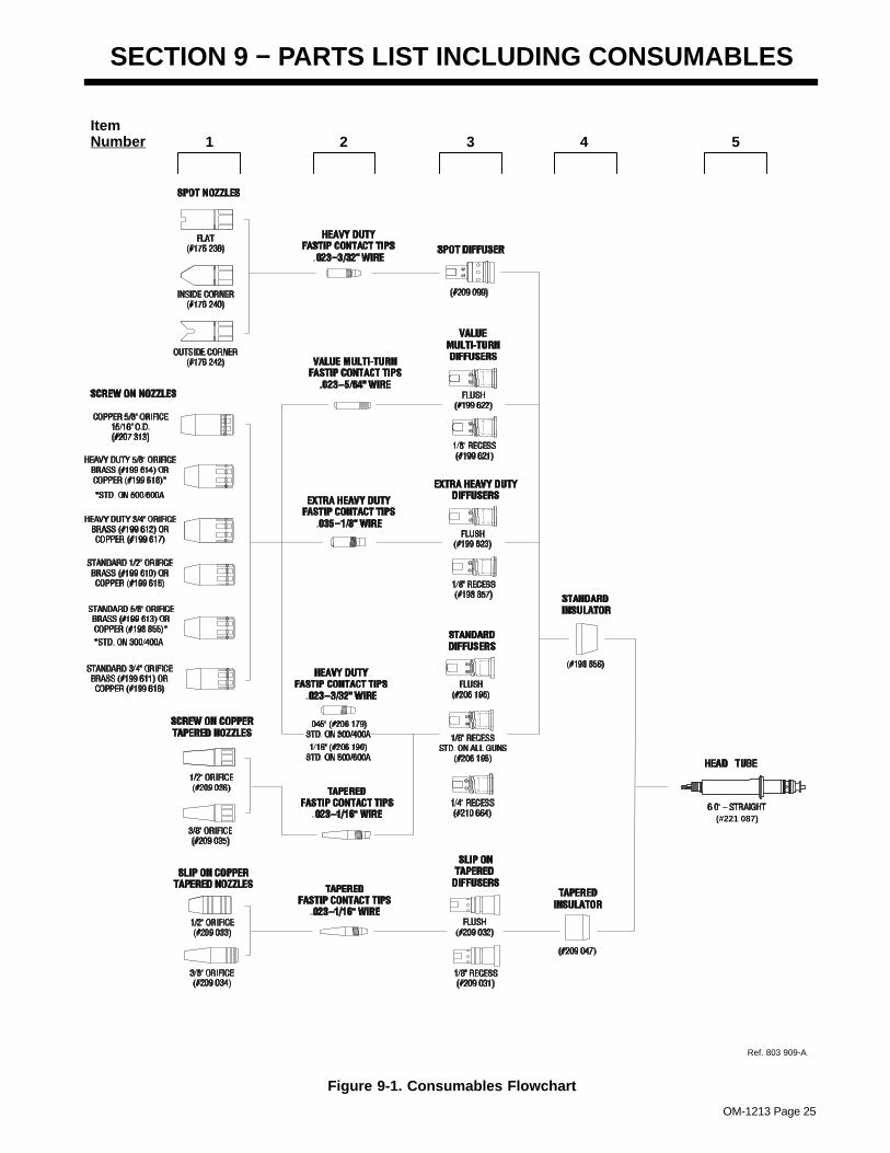
SECTION 9 − PARTS LIST INCLUDING CONSUMABLES
Item Number 1 2 3 4 5
Ref. 803 909-A
(#221 087)
Figure 9-1. Consumables Flowchart
OM-1213 Page 26
DescriptionPartNo.
ItemNo.
Figure 9-1. Consumables Flowchart
Quantity
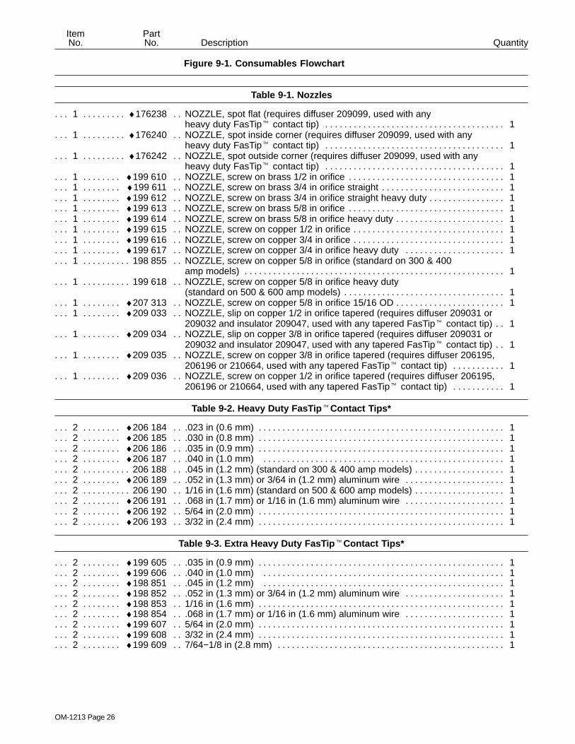
Table 9-1. Nozzles
1 ♦176238 NOZZLE, spot flat (requires diffuser 209099, used with any. . . . . . . . . . . . . . heavy duty FasTip� contact tip) 1. . . . . . . . . . . . . . . . . . . . . . . . . . . . . . . . . . . . . .
1 ♦176240 NOZZLE, spot inside corner (requires diffuser 209099, used with any. . . . . . . . . . . . . . heavy duty FasTip� contact tip) 1. . . . . . . . . . . . . . . . . . . . . . . . . . . . . . . . . . . . . .
1 ♦176242 NOZZLE, spot outside corner (requires diffuser 209099, used with any. . . . . . . . . . . . . . heavy duty FasTip� contact tip) 1. . . . . . . . . . . . . . . . . . . . . . . . . . . . . . . . . . . . . .
1 ♦199 610 NOZZLE, screw on brass 1/2 in orifice 1. . . . . . . . . . . . . . . . . . . . . . . . . . . . . . . . . . . . . . . . . . . . . . 1 ♦199 611 NOZZLE, screw on brass 3/4 in orifice straight 1. . . . . . . . . . . . . . . . . . . . . . . . . . . . . . . . . . . . . . . 1 ♦199 612 NOZZLE, screw on brass 3/4 in orifice straight heavy duty 1. . . . . . . . . . . . . . . . . . . . . . . . . . . . . 1 ♦199 613 NOZZLE, screw on brass 5/8 in orifice 1. . . . . . . . . . . . . . . . . . . . . . . . . . . . . . . . . . . . . . . . . . . . . . 1 ♦199 614 NOZZLE, screw on brass 5/8 in orifice heavy duty 1. . . . . . . . . . . . . . . . . . . . . . . . . . . . . . . . . . . . 1 ♦199 615 NOZZLE, screw on copper 1/2 in orifice 1. . . . . . . . . . . . . . . . . . . . . . . . . . . . . . . . . . . . . . . . . . . . . 1 ♦199 616 NOZZLE, screw on copper 3/4 in orifice 1. . . . . . . . . . . . . . . . . . . . . . . . . . . . . . . . . . . . . . . . . . . . . 1 ♦199 617 NOZZLE, screw on copper 3/4 in orifice heavy duty 1. . . . . . . . . . . . . . . . . . . . . . . . . . . . . . . . . . 1 198 855 NOZZLE, screw on copper 5/8 in orifice (standard on 300 & 400 . . . . . . . . . . . . . . .
amp models) 1. . . . . . . . . . . . . . . . . . . . . . . . . . . . . . . . . . . . . . . . . . . . . . . . . . . . . . . 1 199 618 NOZZLE, screw on copper 5/8 in orifice heavy duty . . . . . . . . . . . . . . .
(standard on 500 & 600 amp models) 1. . . . . . . . . . . . . . . . . . . . . . . . . . . . . . . . . . 1 ♦207 313 NOZZLE, screw on copper 5/8 in orifice 15/16 OD 1. . . . . . . . . . . . . . . . . . . . . . . . . . . . . . . . . . . . 1 ♦209 033 NOZZLE, slip on copper 1/2 in orifice tapered (requires diffuser 209031 or . . . . . . . . . . . . .
209032 and insulator 209047, used with any tapered FasTip� contact tip) 1. . 1 ♦209 034 NOZZLE, slip on copper 3/8 in orifice tapered (requires diffuser 209031 or . . . . . . . . . . . . .
209032 and insulator 209047, used with any tapered FasTip� contact tip) 1. . 1 ♦209 035 NOZZLE, screw on copper 3/8 in orifice tapered (requires diffuser 206195, . . . . . . . . . . . . .
206196 or 210664, used with any tapered FasTip� contact tip) 1. . . . . . . . . . . 1 ♦209 036 NOZZLE, screw on copper 1/2 in orifice tapered (requires diffuser 206195, . . . . . . . . . . . . .
206196 or 210664, used with any tapered FasTip� contact tip) 1. . . . . . . . . . .
Table 9-2. Heavy Duty FasTip �Contact Tips*
2 ♦206 184 .023 in (0.6 mm) 1. . . . . . . . . . . . . . . . . . . . . . . . . . . . . . . . . . . . . . . . . . . . . . . . . . . . . . . . . . . . . . . . . 2 ♦206 185 .030 in (0.8 mm) 1. . . . . . . . . . . . . . . . . . . . . . . . . . . . . . . . . . . . . . . . . . . . . . . . . . . . . . . . . . . . . . . . . 2 ♦206 186 .035 in (0.9 mm) 1. . . . . . . . . . . . . . . . . . . . . . . . . . . . . . . . . . . . . . . . . . . . . . . . . . . . . . . . . . . . . . . . . 2 ♦206 187 .040 in (1.0 mm) 1. . . . . . . . . . . . . . . . . . . . . . . . . . . . . . . . . . . . . . . . . . . . . . . . . . . . . . . . . . . . . . . . 2 206 188 .045 in (1.2 mm) (standard on 300 & 400 amp models) 1. . . . . . . . . . . . . . . . . . . . . . . . . . . . . . . . . . 2 ♦206 189 .052 in (1.3 mm) or 3/64 in (1.2 mm) aluminum wire 1. . . . . . . . . . . . . . . . . . . . . . . . . . . . . . . . . . 2 206 190 1/16 in (1.6 mm) (standard on 500 & 600 amp models) 1. . . . . . . . . . . . . . . . . . . . . . . . . . . . . . . . . . 2 ♦206 191 .068 in (1.7 mm) or 1/16 in (1.6 mm) aluminum wire 1. . . . . . . . . . . . . . . . . . . . . . . . . . . . . . . . . . 2 ♦206 192 5/64 in (2.0 mm) 1. . . . . . . . . . . . . . . . . . . . . . . . . . . . . . . . . . . . . . . . . . . . . . . . . . . . . . . . . . . . . . . . . 2 ♦206 193 3/32 in (2.4 mm) 1. . . . . . . . . . . . . . . . . . . . . . . . . . . . . . . . . . . . . . . . . . . . . . . . . . . . . . . . . . . . . . . . .
Table 9-3. Extra Heavy Duty FasTip �Contact Tips*
2 ♦199 605 .035 in (0.9 mm) 1. . . . . . . . . . . . . . . . . . . . . . . . . . . . . . . . . . . . . . . . . . . . . . . . . . . . . . . . . . . . . . . . . 2 ♦199 606 .040 in (1.0 mm) 1. . . . . . . . . . . . . . . . . . . . . . . . . . . . . . . . . . . . . . . . . . . . . . . . . . . . . . . . . . . . . . . . 2 ♦198 851 .045 in (1.2 mm) 1. . . . . . . . . . . . . . . . . . . . . . . . . . . . . . . . . . . . . . . . . . . . . . . . . . . . . . . . . . . . . . . . 2 ♦198 852 .052 in (1.3 mm) or 3/64 in (1.2 mm) aluminum wire 1. . . . . . . . . . . . . . . . . . . . . . . . . . . . . . . . . . 2 ♦198 853 1/16 in (1.6 mm) 1. . . . . . . . . . . . . . . . . . . . . . . . . . . . . . . . . . . . . . . . . . . . . . . . . . . . . . . . . . . . . . . . . 2 ♦198 854 .068 in (1.7 mm) or 1/16 in (1.6 mm) aluminum wire 1. . . . . . . . . . . . . . . . . . . . . . . . . . . . . . . . . . 2 ♦199 607 5/64 in (2.0 mm) 1. . . . . . . . . . . . . . . . . . . . . . . . . . . . . . . . . . . . . . . . . . . . . . . . . . . . . . . . . . . . . . . . . 2 ♦199 608 3/32 in (2.4 mm) 1. . . . . . . . . . . . . . . . . . . . . . . . . . . . . . . . . . . . . . . . . . . . . . . . . . . . . . . . . . . . . . . . . 2 ♦199 609 7/64−1/8 in (2.8 mm) 1. . . . . . . . . . . . . . . . . . . . . . . . . . . . . . . . . . . . . . . . . . . . . . . . . . . . . . . . . . . . .
OM-1213 Page 27
DescriptionPartNo.
ItemNo.
Figure 9-1. Consumables Flowchart (Continued)
Quantity
Table 9-4. Tapered FasTip � Contact Tips*
2 ♦209024 .023 in (0.6 mm) 1. . . . . . . . . . . . . . . . . . . . . . . . . . . . . . . . . . . . . . . . . . . . . . . . . . . . . . . . . . . . . . . . . . 2 ♦209025 .030 in (0.8 mm) 1. . . . . . . . . . . . . . . . . . . . . . . . . . . . . . . . . . . . . . . . . . . . . . . . . . . . . . . . . . . . . . . . . . 2 ♦209026 .035 in (0.9 mm) 1. . . . . . . . . . . . . . . . . . . . . . . . . . . . . . . . . . . . . . . . . . . . . . . . . . . . . . . . . . . . . . . . . . 2 ♦209027 .045 in (1.2 mm) 1. . . . . . . . . . . . . . . . . . . . . . . . . . . . . . . . . . . . . . . . . . . . . . . . . . . . . . . . . . . . . . . . . . 2 ♦209028 3/64 in (1.2 mm) 1. . . . . . . . . . . . . . . . . . . . . . . . . . . . . . . . . . . . . . . . . . . . . . . . . . . . . . . . . . . . . . . . . . 2 ♦209029 .052 in (1.3 mm) 1. . . . . . . . . . . . . . . . . . . . . . . . . . . . . . . . . . . . . . . . . . . . . . . . . . . . . . . . . . . . . . . . . . 2 ♦209030 1/16 in (1.6 mm) 1. . . . . . . . . . . . . . . . . . . . . . . . . . . . . . . . . . . . . . . . . . . . . . . . . . . . . . . . . . . . . . . . . .
Table 9-5. Value Multi−Turn Contact Tips*
2 ♦087 300 .023 in (0.6 mm) 1. . . . . . . . . . . . . . . . . . . . . . . . . . . . . . . . . . . . . . . . . . . . . . . . . . . . . . . . . . . . . . . . . 2 ♦071 825 .030 in (0.9 mm) 1. . . . . . . . . . . . . . . . . . . . . . . . . . . . . . . . . . . . . . . . . . . . . . . . . . . . . . . . . . . . . . . . . 2 ♦054 202 .035 in (0.9 mm) 1. . . . . . . . . . . . . . . . . . . . . . . . . . . . . . . . . . . . . . . . . . . . . . . . . . . . . . . . . . . . . . . . . 2 ♦054 201 .045 in (1.2 mm) 1. . . . . . . . . . . . . . . . . . . . . . . . . . . . . . . . . . . . . . . . . . . . . . . . . . . . . . . . . . . . . . . . 2 ♦199 593 .3/64 in (1.2 mm) aluminum wire 1. . . . . . . . . . . . . . . . . . . . . . . . . . . . . . . . . . . . . . . . . . . . . . . . . . . 2 ♦044 006 .052 in (1.3 mm) 1. . . . . . . . . . . . . . . . . . . . . . . . . . . . . . . . . . . . . . . . . . . . . . . . . . . . . . . . . . . . . . . . . 2 ♦047 566 1/16 in (1.6 mm) 1. . . . . . . . . . . . . . . . . . . . . . . . . . . . . . . . . . . . . . . . . . . . . . . . . . . . . . . . . . . . . . . . . 2 ♦202 933 1/16 in (1.6 mm) aluminum wire 1. . . . . . . . . . . . . . . . . . . . . . . . . . . . . . . . . . . . . . . . . . . . . . . . . . . . 2 ♦199 594 .068 in (1.7 mm) 1. . . . . . . . . . . . . . . . . . . . . . . . . . . . . . . . . . . . . . . . . . . . . . . . . . . . . . . . . . . . . . . . . 2 ♦047 565 5/64 in (2.0 mm) 1. . . . . . . . . . . . . . . . . . . . . . . . . . . . . . . . . . . . . . . . . . . . . . . . . . . . . . . . . . . . . . . . .
Table 9-6. Gas Diffusers
3 ♦198 857 1/8 in tip recess − for extra heavy duty FasTip contact tips 1. . . . . . . . . . . . . . . . . . . . . . . . . . . . . 3 ♦199 623 Flush tip − for extra heavy duty FasTip contact tips 1. . . . . . . . . . . . . . . . . . . . . . . . . . . . . . . . . . . 3 ♦199 621 1/8 in tip recess − for value multi−turn contact tips 1. . . . . . . . . . . . . . . . . . . . . . . . . . . . . . . . . . . . 3 ♦199 622 Flush tip − for value multi−turn contact tips 1. . . . . . . . . . . . . . . . . . . . . . . . . . . . . . . . . . . . . . . . . . 3 206 195 1/8 in tip recess − for heavy duty FasTip contact tips. . . . . . . . . . . . . . .
(standard on all guns) 1. . . . . . . . . . . . . . . . . . . . . . . . . . . . . . . . . . . . . . . . . . . . . . . 3 ♦210 664 1/4 in tip recess − for heavy duty FasTip contact tips 1. . . . . . . . . . . . . . . . . . . . . . . . . . . . . . . . . . 3 ♦206 196 Flush tip − for heavy duty FasTip contact tips 1. . . . . . . . . . . . . . . . . . . . . . . . . . . . . . . . . . . . . . . . 3 ♦209 031 Slip on recessed diffuser (requires nozzle 209033 or 209034. . . . . . . . . . . . .
and insulator 209047, used with any tapered FasTip contact tip) 1. . . . . . . . . . 3 ♦209 032 Slip on flush diffuser (requires nozzle 209033 or 209034. . . . . . . . . . . . .
and insulator 209047, used with any tapered FasTip contact tip) 1. . . . . . . . . . 3 ♦209 099 Spot diffuser (requires spot nozzle 176238 or176240 or 176242) 1. . . . . . . . . . . . . . . . . . . . . . .
Table 9-7. Insulators
4 198 856 INSULATOR, Rubber 1. . . . . . . . . . . . . . . . . . . . . . . . . . . . . . . . . . . . . . . . . . . . . . . . . . . . . . . . . . . . . . . 4 209 047 INSULATOR, Teflon (required when using diffuser 209031 or 209032. . . . . . . . . . . . . . .
with nozzle 209033 or 209034) 1. . . . . . . . . . . . . . . . . . . . . . . . . . . . . . . . . . . . . . .
Table 9-8. Head Tubes
5 221 087 BARREL ASSY, air cooled pistol 1. . . . . . . . . . . . . . . . . . . . . . . . . . . . . . . . . . . . . . . . . . . . . . . . . . . . .
♦OPTIONAL*All contact tips are packaged in bags of 25.BE SURE TO PROVIDE MODEL WHEN ORDERING REPLACEMENT PARTS.To maintain the factory original performance of your equipment, use only Manufacturer’s SuggestedReplacement Parts. Model is required when ordering parts from your local distributor.

Notes

Notes
Over 80,000 trained
since 1930!400 Trade Square East, Troy, Ohio 45373
1-800-332-9448 www.welding.org
Start Your Professional
Welding Career Now!

Notes
Warranty Questions?
Call1-800-4-A-MILLERfor your localMiller distributor.
miller_warr 6/04
Your distributor also givesyou ...
ServiceYou always get the fast,reliable response youneed. Most replacementparts can be in yourhands in 24 hours.
SupportNeed fast answers to thetough welding questions?Contact your distributor.The expertise of thedistributor and Miller isthere to help you, everystep of the way.
Effective January 1, 2004(Equipment with a serial number preface of “LE” or newer)This limited warranty supersedes all previous Miller warranties and is exclusive with no other
guarantees or warranties expressed or implied.
LIMITED WARRANTY − Subject to the terms and conditionsbelow, Miller Electric Mfg. Co., Appleton, Wisconsin, warrants toits original retail purchaser that new Miller equipment sold afterthe effective date of this limited warranty is free of defects inmaterial and workmanship at the time it is shipped by Miller.THIS WARRANTY IS EXPRESSLY IN LIEU OF ALL OTHERWARRANTIES, EXPRESS OR IMPLIED, INCLUDING THEWARRANTIES OF MERCHANTABILITY AND FITNESS.
Within the warranty periods listed below, Miller will repair orreplace any warranted parts or components that fail due to suchdefects in material or workmanship. Miller must be notified inwriting within thirty (30) days of such defect or failure, at whichtime Miller will provide instructions on the warranty claimprocedures to be followed.
Miller shall honor warranty claims on warranted equipmentlisted below in the event of such a failure within the warrantytime periods. All warranty time periods start on the date that theequipment was delivered to the original retail purchaser, or oneyear after the equipment is sent to a North American distributoror eighteen months after the equipment is sent to anInternational distributor.
1. 5 Years Parts — 3 Years Labor
* Original main power rectifiers* Inverters (input and output rectifiers only)
2. 3 Years — Parts and Labor
* Transformer/Rectifier Power Sources* Plasma Arc Cutting Power Sources* Semi-Automatic and Automatic Wire Feeders* Inverter Power Sources (Unless Otherwise Stated)* Water Coolant Systems (Integrated)* Intellitig* Maxstar 150* Engine Driven Welding Generators
(NOTE: Engines are warranted separately bythe engine manufacturer.)
3. 1 Year — Parts and Labor Unless Specified
* DS-2 Wire Feeder* Motor Driven Guns (w/exception of Spoolmate
Spoolguns)* Process Controllers* Positioners and Controllers* Automatic Motion Devices* RFCS Foot Controls* Induction Heating Power Sources and Coolers* Water Coolant Systems (Non-Integrated)* Flowgauge and Flowmeter Regulators (No Labor)* HF Units* Grids* Maxstar 85, 140* Spot Welders* Load Banks* Arc Stud Power Sources & Arc Stud Guns* Racks* Running Gear/Trailers* Plasma Cutting Torches (except APT & SAF
Models)* Field Options
(NOTE: Field options are covered under TrueBlue for the remaining warranty period of theproduct they are installed in, or for a minimum ofone year — whichever is greater.)
4. 6 Months — Batteries
5. 90 Days — Parts
* MIG Guns/TIG Torches
* Induction Heating Coils and Blankets
* APT & SAF Model Plasma Cutting Torches
* Remote Controls
* Accessory Kits
* Replacement Parts (No labor)
* Spoolmate Spoolguns
* Canvas Covers
Miller’s True Blue Limited Warranty shall not apply to:
1. Consumable components; such as contact tips,cutting nozzles, contactors, brushes, slip rings,relays or parts that fail due to normal wear. (Exception:brushes, slip rings, and relays are covered on Bobcat,Trailblazer, and Legend models.)
2. Items furnished by Miller, but manufactured by others,such as engines or trade accessories. These items arecovered by the manufacturer’s warranty, if any.
3. Equipment that has been modified by any party other thanMiller, or equipment that has been improperly installed,improperly operated or misused based upon industrystandards, or equipment which has not had reasonableand necessary maintenance, or equipment which hasbeen used for operation outside of the specifications for theequipment.
MILLER PRODUCTS ARE INTENDED FOR PURCHASE ANDUSE BY COMMERCIAL/INDUSTRIAL USERS ANDPERSONS TRAINED AND EXPERIENCED IN THE USE ANDMAINTENANCE OF WELDING EQUIPMENT.
In the event of a warranty claim covered by this warranty, theexclusive remedies shall be, at Miller’s option: (1) repair; or (2)replacement; or, where authorized in writing by Miller inappropriate cases, (3) the reasonable cost of repair orreplacement at an authorized Miller service station; or (4)payment of or credit for the purchase price (less reasonabledepreciation based upon actual use) upon return of the goods atcustomer’s risk and expense. Miller’s option of repair orreplacement will be F.O.B., Factory at Appleton, Wisconsin, orF.O.B. at a Miller authorized service facility as determined byMiller. Therefore no compensation or reimbursement fortransportation costs of any kind will be allowed.
TO THE EXTENT PERMITTED BY LAW, THE REMEDIESPROVIDED HEREIN ARE THE SOLE AND EXCLUSIVEREMEDIES. IN NO EVENT SHALL MILLER BE LIABLE FORDIRECT, INDIRECT, SPECIAL, INCIDENTAL ORCONSEQUENTIAL DAMAGES (INCLUDING LOSS OFPROFIT), WHETHER BASED ON CONTRACT, TORT ORANY OTHER LEGAL THEORY.
ANY EXPRESS WARRANTY NOT PROVIDED HEREIN ANDANY IMPLIED WARRANTY, GUARANTY ORREPRESENTATION AS TO PERFORMANCE, AND ANYREMEDY FOR BREACH OF CONTRACT TORT OR ANYOTHER LEGAL THEORY WHICH, BUT FOR THISPROVISION, MIGHT ARISE BY IMPLICATION, OPERATIONOF LAW, CUSTOM OF TRADE OR COURSE OF DEALING,INCLUDING ANY IMPLIED WARRANTY OFMERCHANTABILITY OR FITNESS FOR PARTICULARPURPOSE, WITH RESPECT TO ANY AND ALL EQUIPMENTFURNISHED BY MILLER IS EXCLUDED AND DISCLAIMEDBY MILLER.
Some states in the U.S.A. do not allow limitations of how long animplied warranty lasts, or the exclusion of incidental, indirect,special or consequential damages, so the above limitation orexclusion may not apply to you. This warranty provides specificlegal rights, and other rights may be available, but may varyfrom state to state.
In Canada, legislation in some provinces provides for certainadditional warranties or remedies other than as stated herein,and to the extent that they may not be waived, the limitationsand exclusions set out above may not apply. This LimitedWarranty provides specific legal rights, and other rights may beavailable, but may vary from province to province.

PRINTED IN USA 2004 Miller Electric Mfg. Co. 1/04
Miller Electric Mfg. Co.An Illinois Tool Works Company1635 West Spencer StreetAppleton, WI 54914 USA
International Headquarters−USAUSA Phone: 920-735-4505 Auto-AttendedUSA & Canada FAX: 920-735-4134International FAX: 920-735-4125
European Headquarters −United KingdomPhone: 44 (0) 1204-593493FAX: 44 (0) 1204-598066
www.MillerWelds.com
Model Name Serial/Style Number
Purchase Date (Date which equipment was delivered to original customer.)
Distributor
Address
City
State Zip
Please complete and retain with your personal records.
Always provide Model Name and Serial/Style Number.
Call 1-800-4-A-Miller or see our website at www.MillerWelds.comto locate a DISTRIBUTOR or SERVICE AGENCY near you.
Welding Supplies and Consumables
Options and Accessories
Personal Safety Equipment
Service and Repair
Replacement Parts
Training (Schools, Videos, Books)
Technical Manuals (Servicing Informationand Parts)
Circuit Diagrams
Welding Process Handbooks
Contact the Delivering Carrier to:
For Service
Owner’s Record
File a claim for loss or damage duringshipment.
For assistance in filing or settling claims, contactyour distributor and/or equipment manufacturer’sTransportation Department.
Contact your Distributor for: