speedport plus -...
TRANSCRIPT

Speedport Plus
Instruction manual
1
Contents
CHAPTER 1 SAFETY PRECAUTIONS .................................................................................... 5 CHAPTER 2 OVERVIEW ..................................................................................................... 7 CHAPTER 3 CONFIGURATION PREPARATION ................................................................... 14 3.1 HARDWARE CONNECTION ........................................................................................ 15
3.2 LOGGING IN TO THE DEVICE................................................................................................. 26
3.3 OVERVIEW........................................................................................................................ 39
CHAPTER 4 STATUS ........................................................................................................ 44
4.1 SYSTEM INFORMATION ....................................................................................................... 44
4.1.1 VERSION NUMBERS AND DSL INFORMATION ....................................................................... 44
4.1.2 3G DONGLE STATUS........................................................................................................ 45
4.1.3 SYSTEM MESSAGES.......................................................................................................... 46
4.2 WAN STATUS ................................................................................................................... 47
CHAPTER 5 INTERNET MENU .......................................................................................... 49
5.1 CONNECTION OPTION.................................................................................................. 49
5.1.1 STATUS ..................................................................................................................... 49
5.1.2 XDSL MODULATION.................................................................................................... 49
5.1.3 INTENET CONNECTION................................................................................................. 52
5.1.4 3G/LTE WAN ............................................................................................................ 55
5.1.5 WAN Automatic Failover ............................................................................................ 56
5.1.6 PORT BINDING ............................................................................................................... 57
5.2 FEATURES.................................................................................................................. 58
5.2.1 DDNS.................................................................................................................. 58
5.2.2 PORT FORWARDING .................................................................................................... 60
5.2.3 PORT TRIGGER ........................................................................................................... 62
5.2.4 FILTER AND TIME RULE ................................................................................................ 65
5.3 ADVANCED SETTINGS .................................................................................................. 69
5.3.1 ROUTING................................................................................................................... 69
5.3.1.1 STATIC ROUTING.......................................................................................................... 69
5.3.1.2 IPV6 STATIC ROUTING.................................................................................................. 71
5.3.1.3 RIP........................................................................................................................... 72
5.3.2 SECURITY....................................................................................................................... 73
5.3.2.1 FIREWALL.............................................................................................................. 73
2

5.3.2.2 IP FILTER .................................................................................................................... 74
5.3.2.3 DMZ ......................................................................................................................... 79
5.3.2.4 ALG .......................................................................................................................... 80
5.3.2.5 E-MAIL ABUSE DETECTION ............................................................................................. 80
CHAPTER 6 HOME NETWORK MENU............................................................................... 83
6.1 BASIC WLAN SETTINGS ...................................................................................................... 83
6.1.1 SSID SETTINGS............................................................................................................... 84
6.1.2 WLAN TIME RULE........................................................................................................... 87
6.1.3 SEND SETTINGS............................................................................................................... 88
6.1.4 WMM ......................................................................................................................... 92
6.1.5 WIRELESS CLIENT............................................................................................................ 94
6.2 MANAGE WLAN ACCESS .................................................................................................... 95
6.2.1 ACCESS LIMIT ................................................................................................................. 95
6.2.2 WPS ............................................................................................................................ 97
6.3 HOME NETWORK ( LAN)................................................................................................... 101
6.3.1 OVERVIEW ON THE DEVICES IN THE HOME NETWORK .......................................................... 101
6.3.2 NAME AND ADDRESS OF THE ROUTER ............................................................................... 104
6.3.3 DHCP........................................................................................................................ 108
6.4 NETWORK STORAGE ......................................................................................................... 110
6.4.1 NETWORK STORAGE OVERVIEW ....................................................................................... 110
6.4.2 MANAGE USER............................................................................................................. 111
6.4.3 ACCESS VIA FTP/FTPS .................................................................................................. 113
6.4.4 GUEST ACCESS.............................................................................................................. 114
6.4.5 SETTINGS..................................................................................................................... 115
6.5 UPNP ............................................................................................................................ 121
CHAPTER 7 TELEPHONY................................................................................................ 122
7.1 SIP PROVIDERS................................................................................................................ 122
7.2 SIP ACCOUNTS ................................................................................................................ 124
7. 3 TELEPHONY PORTS .......................................................................................................... 126
7. 4 ADVANCED..................................................................................................................... 127
7. 5 MEDIA .......................................................................................................................... 128
7.6 FAX ............................................................................................................................... 130
7.7 SUPPLEMENTARY SERVICE ................................................................................................. 131
7.8 DIAL PLAN ...................................................................................................................... 132
7.9 CALL LOG ....................................................................................................................... 133
7.10 SPEED DIAL................................................................................................................... 136
3
CHAPTER 8 SETTINGS ................................................................................................... 137
8.1 CHANGE DEVICE PASSWORD............................................................................................... 137
8.2 TR069 ................................................................................................................... 139
8.4 SAVE SETTING ................................................................................................................. 142
8.4.1 BACKUP SETTINGS ......................................................................................................... 142
8.4.2 RESTORE SETTINGS ........................................................................................................ 143
8.5 PROBLEM HANDLING ........................................................................................................ 144
8.5.1 RESTART SPEEDPORT ..................................................................................................... 144
8.5.2 RESET ALL SETTINGS. ..................................................................................................... 144
8.6 FIRMWARE UPDATE.......................................................................................................... 145
8.7 SYSTEM INFORMATION ..................................................................................................... 147
8.8 IGMP SETTINGS .............................................................................................................. 147
8.9 NTP .............................................................................................................................. 148
RESET TO DELIVERY STATUS (RESET) ............................................................................. 149 TROUBLESHOOTING..................................................................................................... 150 TECHNICAL SERVICE ..................................................................................................... 151 DISPOSAL OF OLD DEVICES........................................................................................... 152
4
Chapter 1 Safety Precautions
Please note the following advices, in order to avoid physical injury!
Never open Speedport or the mains plug by yourself.
Never touch the plug contacts with pointed metallic items.
Never install Speedport during a thunderstorm. Never connect or
loosen electrical connections in order to avoid the danger of an
electrical shock.
Always install the electrical ducts, so no one can tread on them or
stumble.
Just operate Speedport with the included mains plug and just connect
it to sockets, which correspond to the standards stated on the
identification label. Never touch the mains plug with wet hands.
Always note the following warnings for installation, setup and
operation of Speedport!
Put Speedport on an anti-slip surface
Place Speedport away from heat sources, direct sunlight and other
electrical devices.
Do not place Speedport on heat sensitive surfaces.
Protect Speedport from moisture, dust, liquids and steams.
Do not store or place Speedport in humid places (i.e. bathroom) or in
hazardous areas.
Never place items on Speedport. The vent openings on Speedport are
necessary for cooling and must not be covered.
Connect Speedport only to the appropriate sockets. Just connect
authorized accessories to Speedport.
Wipe Speedport just with a soft, dry and anti-static cleaning cloth.
Do not use cleaning agents on Speedport.
Never disconnect Speedport from the power source or from its
broadband connection during an automatic configuration or a
firmware update. The following loss of data may cause malfunctioning
of your Speedport.
Speedport may just be repaired by authorized service personnel.
5

Note: Always choose secure passwords! Especially for the device password of
Speedport, the internet access and the wireless home network.
OTE S.A. cannot be hold responsible for damages resulting from improper
use of the device!
6
Chapter 2 Overview
2.1 Product Introduction
Speedport Plus is a broadband router with integrated DSL modem and
makes the connectivity to the internet via VDSL2 (17a &35 b)and ADSL2+ possible. Speedport
carries out the connection setup for all affiliated devices.
For the use in the tethered home network (LAN) up to four devices can be attached
to the LAN plugs of Speedport (by default, LAN4 is dedicated for IPTV). The devices
can communicate with each other within the home network. Speedport supports
wireless (WLAN) as well as tethered home networks (LAN).
USB-Storages, which are connected to Speedport can be used for the easy exchange
of media data and as network storages.
Speedport also offers the functions of a telephone device for internet phone calls.
You can attach two tethered analogue end devices such as telephone, answering
machines or fax devices. Note: Brands or trade names, which are mentioned in this manual serve the
description of the instruction step, which does not mean they are available without
royalties. They remain under all circumstances the property of their respective right
owner.
7
2.2.Packing List
Check package content.
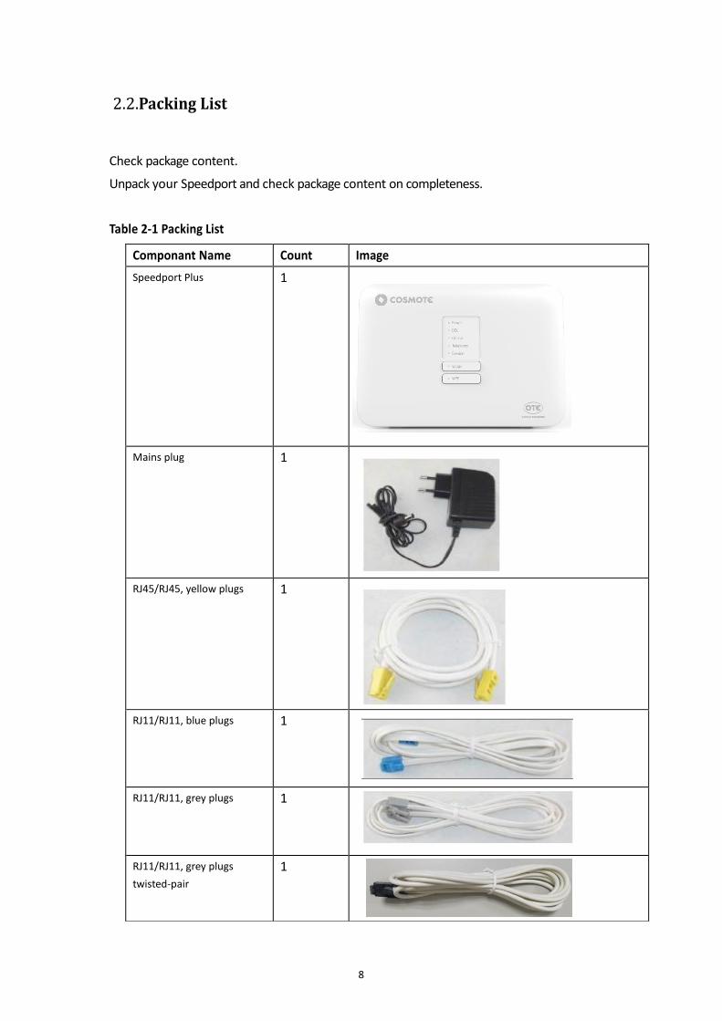
Unpack your Speedport and check package content on completeness. Table 2-1 Packing List
8
Componant Name Count Image
Speedport Plus
1
Mains plug 1
RJ45/RJ45, yellow plugs 1
RJ11/RJ11, blue plugs 1
RJ11/RJ11, grey plugs 1
RJ11/RJ11, grey plugs
twisted-pair
1
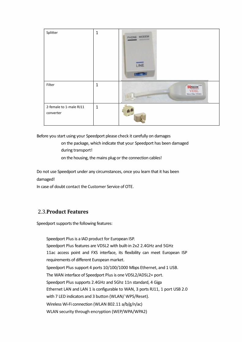
Before you start using your Speedport please check it carefully on damages
on the package, which indicate that your Speedport has been damaged
during transport!
on the housing, the mains plug or the connection cables!
Do not use Speedport under any circumstances, once you learn that it has been
damaged!
In case of doubt contact the Customer Service of OTE.
2.3.Product Features
Speedport supports the following features:
Speedport Plus is a IAD product for European ISP.
Speedport Plus features are VDSL2 with built-in 2x2 2.4GHz and 5GHz
11ac access point and FXS interface, its flexibility can meet European ISP
requirements of different European market.
Speedport Plus support 4 ports 10/100/1000 Mbps Ethernet, and 1 USB.
The WAN interface of Speedport Plus is one VDSL2/ADSL2+ port.
Speedport Plus supports 2.4GHz and 5Ghz 11n standard, 4 Giga
Ethernet LAN and LAN 1 is configurable to WAN, 3 ports RJ11, 1 port USB 2.0
with 7 LED indicators and 3 button (WLAN/ WPS/Reset).
Wireless Wi-Fi connection (WLAN 802.11 a/b/g/n/ac)
WLAN security through encryption (WEP/WPA/WPA2)
Splitter 1
Filter 1
2-female to 1-male RJ11
converter
1

9
2.4.Interfaces and Buttons
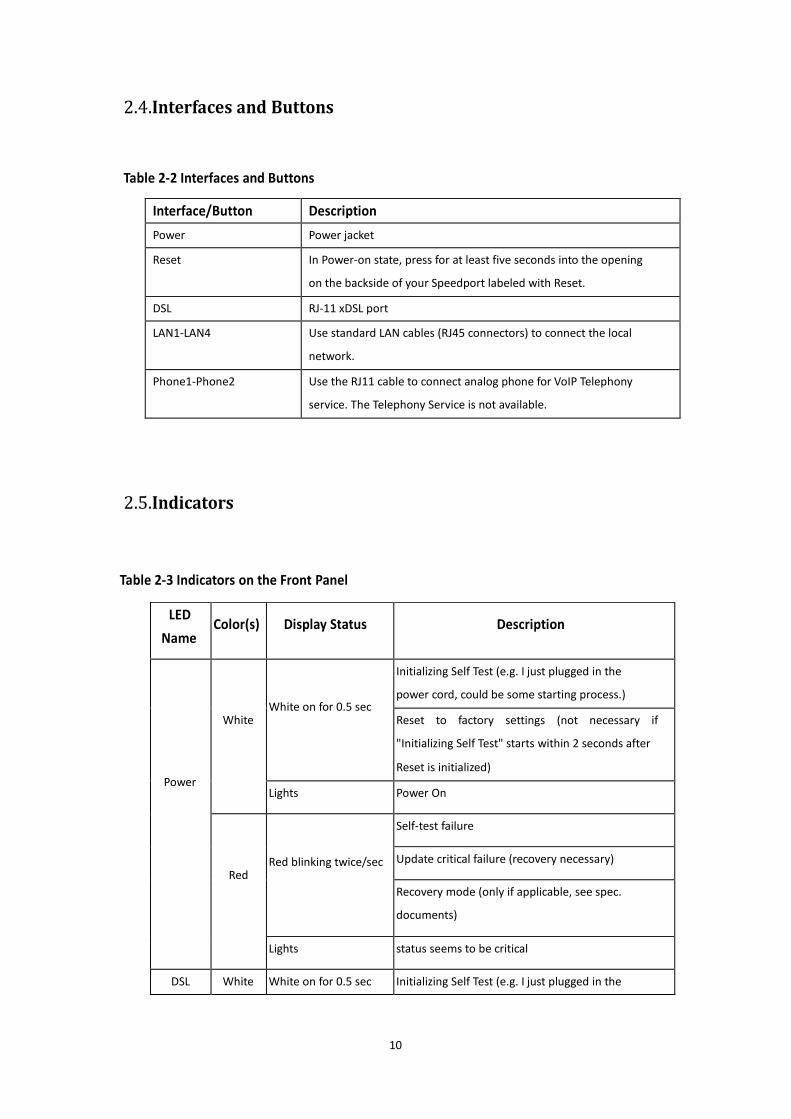
Table 2-2 Interfaces and Buttons
2.5.Indicators
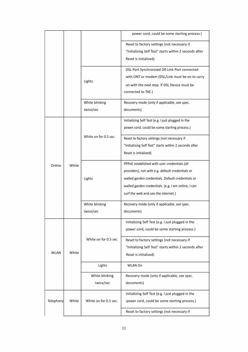
Table 2-3 Indicators on the Front Panel
10
LED
Name Color(s) Display Status Description
Power
White White on for 0.5 sec
Initializing Self Test (e.g. I just plugged in the
power cord, could be some starting process.)
Reset to factory settings (not necessary if
"Initializing Self Test" starts within 2 seconds after
Reset is initialized)
Lights Power On
Red Red blinking twice/sec
Self-test failure
Update critical failure (recovery necessary)
Recovery mode (only if applicable, see spec.
documents)
Lights status seems to be critical
DSL White White on for 0.5 sec Initializing Self Test (e.g. I just plugged in the
Interface/Button Description
Power Power jacket
Reset In Power-on state, press for at least five seconds into the opening
on the backside of your Speedport labeled with Reset.
DSL RJ-11 xDSL port
LAN1-LAN4 Use standard LAN cables (RJ45 connectors) to connect the local
network.
Phone1-Phone2 Use the RJ11 cable to connect analog phone for VoIP Telephony
service. The Telephony Service is not available.
power cord, could be some starting process.)
Reset to factory settings (not necessary if
"Initializing Self Test" starts within 2 seconds after
Reset is initialized)
DSL-Port Synchronized OR Link-Port connected
with ONT or modem (DSL/Link must be on to carry Lights
on with the next step. If DSL Device must be
connected to TAE.)
Online White
White blinking
twice/sec
White on for 0.5 sec.
Lights White blinking
twice/sec
Recovery mode (only if applicable, see spec.
documents)
Initializing Self Test (e.g. I just plugged in the
power cord, could be some starting process.)
Reset to factory settings (not necessary if
"Initializing Self Test" starts within 2 seconds after
Reset is initialized) PPPoE established with user credentials (all
providers), not with e.g. default credentials or
walled garden credentials. Default credentials or
walled garden credentials. (e.g. I am online, I can
surf the web and use the internet.)
Recovery mode (only if applicable, see spec.
documents)
Initializing Self Test (e.g. I just plugged in the
power cord, could be some starting process.)
White on for 0.5 sec Reset to factory settings (not necessary if
"Initializing Self Test" starts within 2 seconds after
WLAN White Reset is initialized)
Lights WLAN On
White blinking
twice/sec
Recovery mode (only if applicable, see spec.
documents)
Initializing Self Test (e.g. I just plugged in the
Telephony White White on for 0.5 sec. power cord, could be some starting process.)
Reset to factory settings (not necessary if
11
"Initializing Self Test" starts within 2 seconds after
Reset is initialized)
Lights Telephony ready to use (ISDN / analogue / VoiP)
White blinking
twice/sec
Recovery mode (only if applicable, see spec.
documents)
The Telephony service is not available.
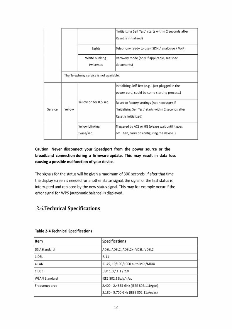
Initializing Self Test (e.g. I just plugged in the
power cord, could be some starting process.)
Yellow on for 0.5 sec. Reset to factory settings (not necessary if
Service Yellow
Yellow blinking
twice/sec
"Initializing Self Test" starts within 2 seconds after
Reset is initialized) Triggered by ACS or HG (please wait until it goes
off. Then, carry on configuring the device. )
Caution: Never disconnect your Speedport from the power source or the
broadband connection during a firmware update. This may result in data loss
causing a possible malfunction of your device.
The signals for the status will be given a maximum of 300 seconds. If after that time
the display screen is needed for another status signal, the signal of the first status is
interrupted and replaced by the new status signal. This may for example occur if the
error signal for WPS (automatic balance) is displayed.
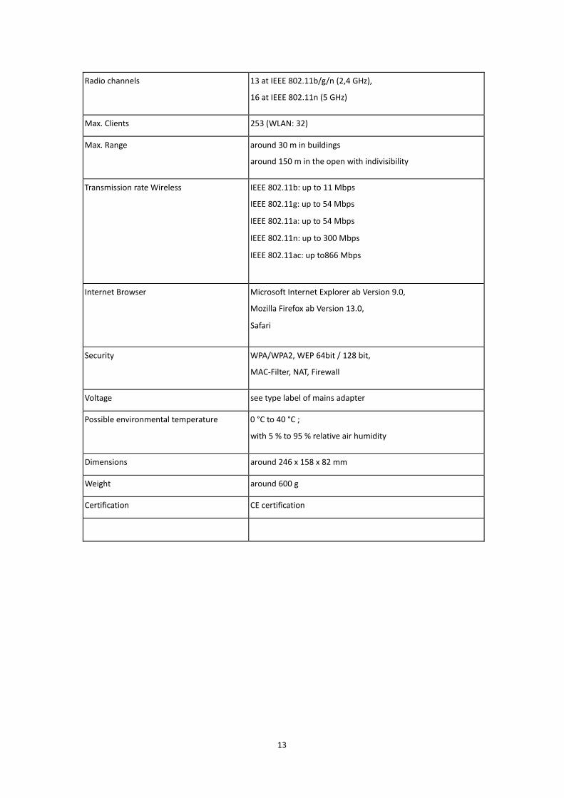
2.6.Technical Specifications
Table 2-4 Technical Specifications
12
Item Specifications
DSL\Standard ADSL, ADSL2, ADSL2+, VDSL, VDSL2
1 DSL RJ11
4 LAN RJ-45, 10/100/1000 auto MDI/MDIX
1 USB USB 1.0 / 1.1 / 2.0
WLAN Standard IEEE 802.11b/g/n/ac
Frequency area 2.400 - 2.4835 GHz (IEEE 802.11b/g/n)
5.180 - 5.700 GHz (IEEE 802.11a/n/ac)
13
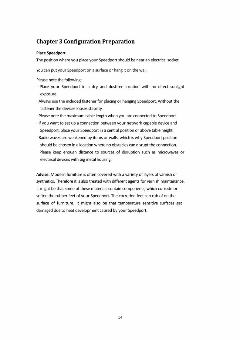
Radio channels 13 at IEEE 802.11b/g/n (2,4 GHz),
16 at IEEE 802.11n (5 GHz)
Max. Clients 253 (WLAN: 32)
Max. Range around 30 m in buildings
around 150 m in the open with indivisibility
Transmission rate Wireless IEEE 802.11b: up to 11 Mbps
IEEE 802.11g: up to 54 Mbps
IEEE 802.11a: up to 54 Mbps
IEEE 802.11n: up to 300 Mbps
IEEE 802.11ac: up to866 Mbps
Internet Browser Microsoft Internet Explorer ab Version 9.0,
Mozilla Firefox ab Version 13.0,
Safari
Security WPA/WPA2, WEP 64bit / 128 bit,
MAC-Filter, NAT, Firewall
Voltage see type label of mains adapter
Possible environmental temperature 0 °C to 40 °C ;
with 5 % to 95 % relative air humidity
Dimensions around 246 x 158 x 82 mm
Weight around 600 g
Certification CE certification
Chapter 3 Configuration Preparation
Place Speedport
The position where you place your Speedport should be near an electrical socket. You can put your Speedport on a surface or hang it on the wall. Please note the following:
· Place your Speedport in a dry and dustfree location with no direct sunlight
exposure.
· Always use the included fastener for placing or hanging Speedport. Without the
fastener the devices looses stability.
· Please note the maximum cable length when you are connected to Speedport.
· If you want to set up a connection between your network capable device and
Speedport, place your Speedport in a central position or above table height.
· Radio waves are weakened by items or walls, which is why Speedport position
should be chosen in a location where no obstacles can disrupt the connection.
· Please keep enough distance to sources of disruption such as microwaves or
electrical devices with big metal housing.
Advise: Modern furniture is often covered with a variety of layers of varnish or
synthetics. Therefore it is also treated with different agents for varnish maintenance.
It might be that some of these materials contain components, which corrode or
soften the rubber feet of your Speedport. The corroded feet can rub of on the
surface of furniture. It might also be that temperature sensitive surfaces get
damaged due to heat development caused by your Speedport.
14
Connect Speedport.
Your Speedport is a high quality product, which will just work to your full
satisfaction, if all necessary conditions for operation are met. So please follow the
instruction carefully, while you connect your Speedport.
Notice: As soon as your Speedport has been connected to the mains power and to
the broadband, the software may be updated automatically (firmware update). In
this case, please do not disconnect the device from AC mains or remove the xDSL
cable while it is automatically updating its software (Service LED blinking) until the
‘Service’ LED stops blinking. Suggestion: Please take a look on the following pages where detailed information is
presented regarding Speedport’s GUI administration.
3.1 Hardware Connection
Notice: Please carry out the installation of Speedport in the following order. With
this procedure, you can be sure that your Speedport is automatically equipped with
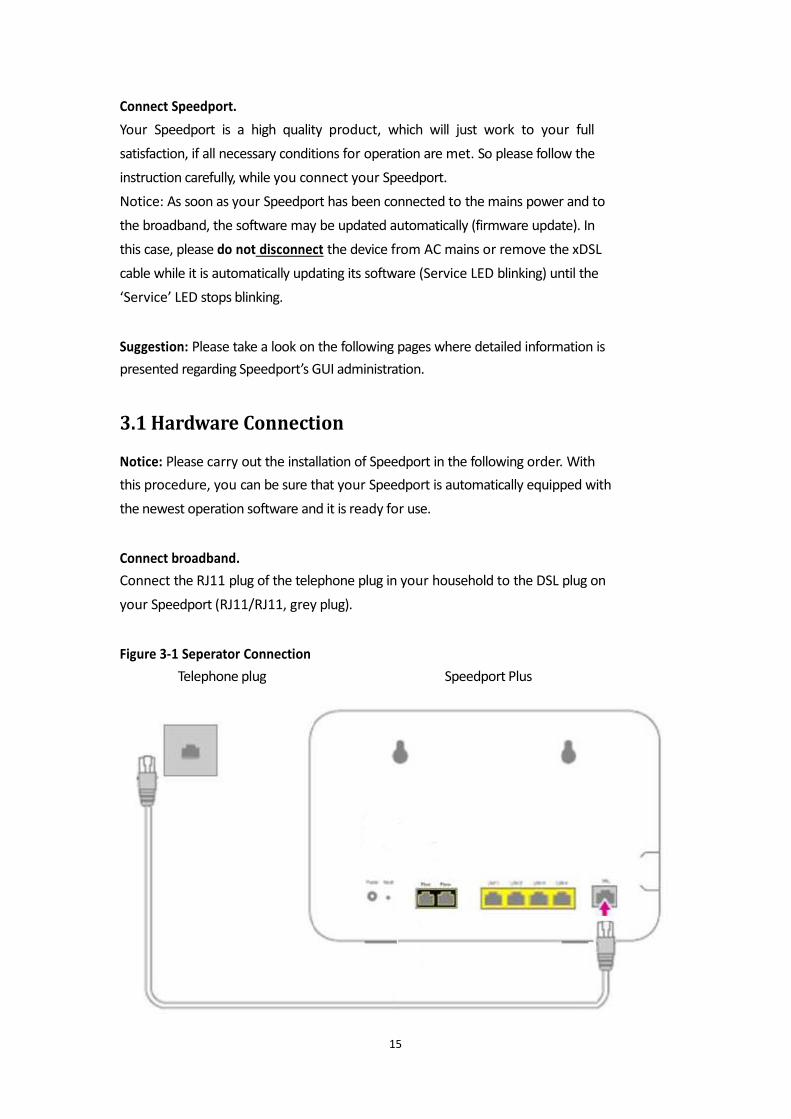
the newest operation software and it is ready for use. Connect broadband.
Connect the RJ11 plug of the telephone plug in your household to the DSL plug on
your Speedport (RJ11/RJ11, grey plug). Figure 3-1 Seperator Connection
Telephone plug Speedport Plus
OTE Speedport W724 vType Ci
15

Notice: If you use a broadband connection with splitter, connect the DSL plug of the
splitter and the DSL plug of your Speedport with the DSL cable for the connection
with splitter (RJ11/RJ11, grey plug).
16
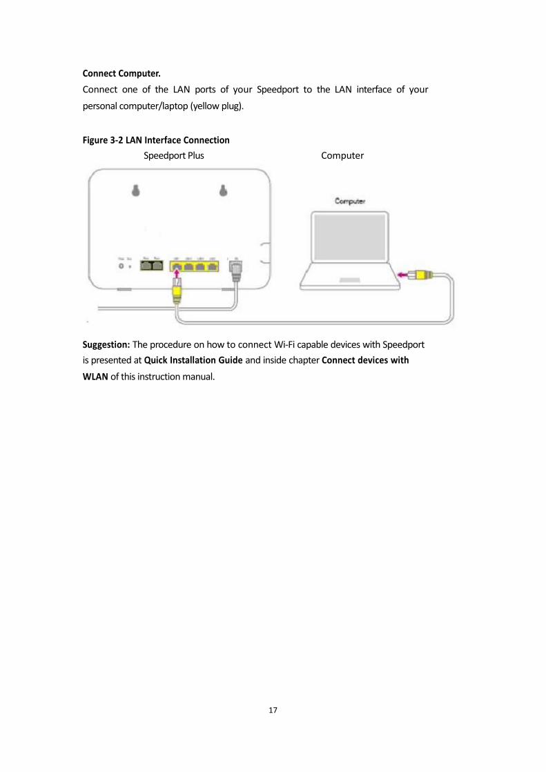
Connect Computer.
Connect one of the LAN ports of your Speedport to the LAN interface of your
personal computer/laptop (yellow plug). Figure 3-2 LAN Interface Connection
Speedport Plus Computer
Suggestion: The procedure on how to connect Wi-Fi capable devices with Speedport
is presented at Quick Installation Guide and inside chapter Connect devices with
WLAN of this instruction manual.
17
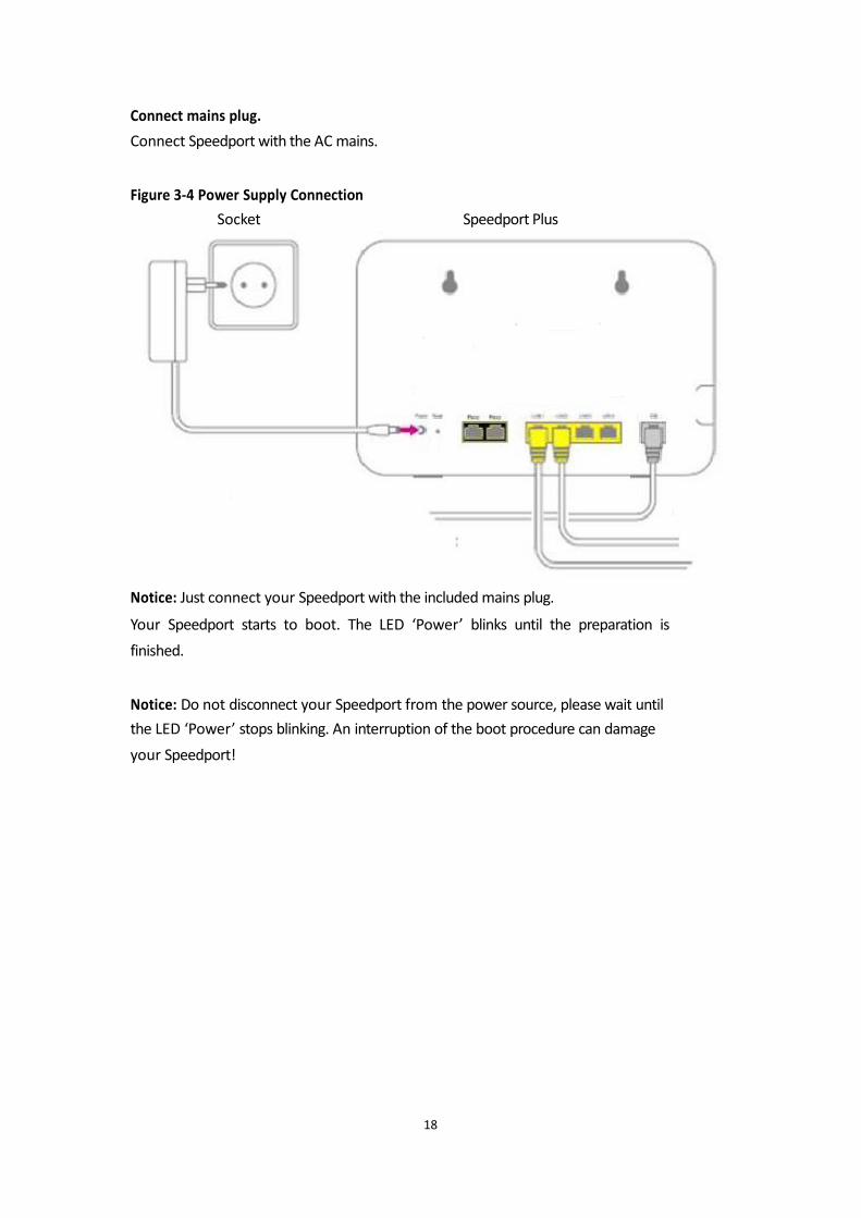
Connect mains plug.
Connect Speedport with the AC mains. Figure 3-4 Power Supply Connection
Socket Speedport Plus
Notice: Just connect your Speedport with the included mains plug.
Your Speedport starts to boot. The LED ‘Power’ blinks until the preparation is
finished. Notice: Do not disconnect your Speedport from the power source, please wait until
the LED ‘Power’ stops blinking. An interruption of the boot procedure can damage
your Speedport!
18
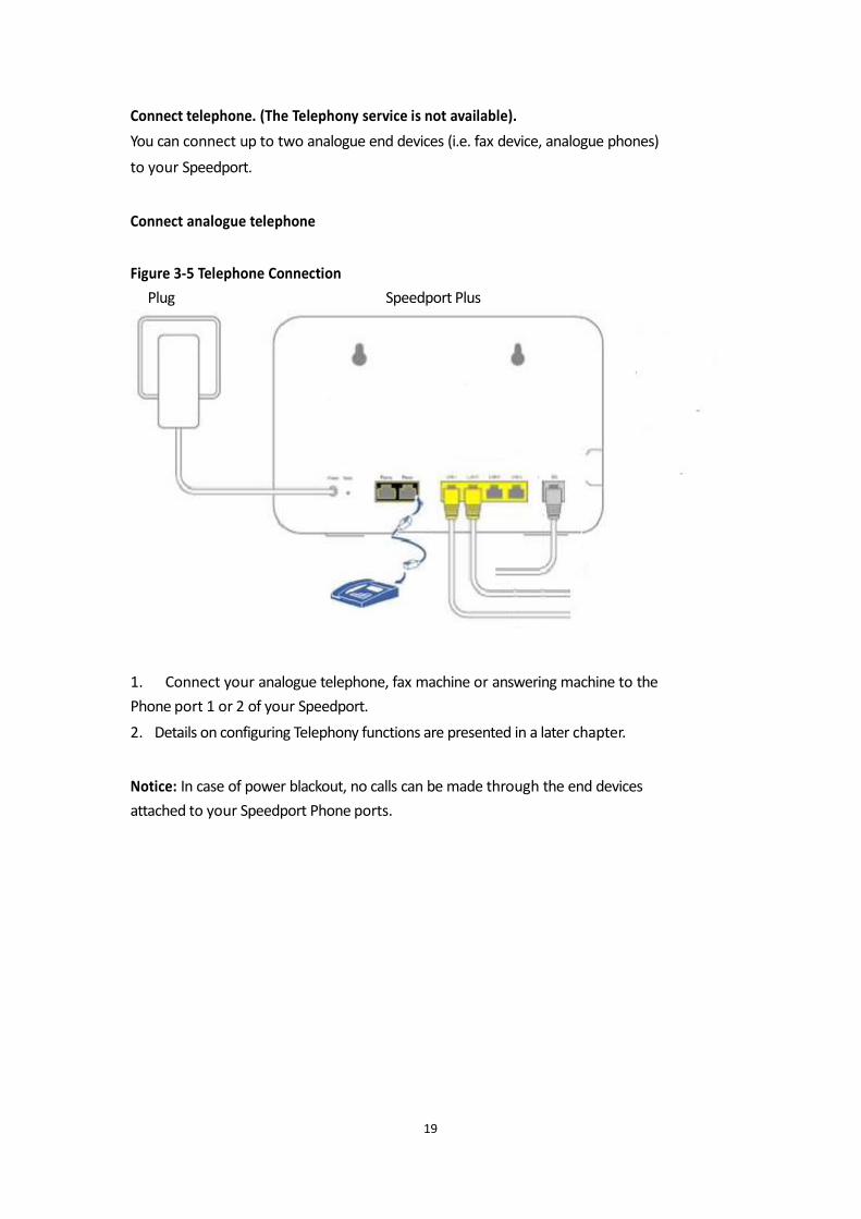
Connect telephone. (The Telephony service is not available).
You can connect up to two analogue end devices (i.e. fax device, analogue phones)
to your Speedport. Connect analogue telephone Figure 3-5 Telephone Connection
Plug Speedport Plus
1. Connect your analogue telephone, fax machine or answering machine to the
Phone port 1 or 2 of your Speedport.
2. Details on configuring Telephony functions are presented in a later chapter. Notice: In case of power blackout, no calls can be made through the end devices
attached to your Speedport Phone ports.
19
Mount your Speedport to the wall.
After connecting all cables, you can attach your Speedport to the wall.
1. Mount two screws (not included in the package) to the wall. Suggestion: Use the marks on the backside of your Speedport as template for
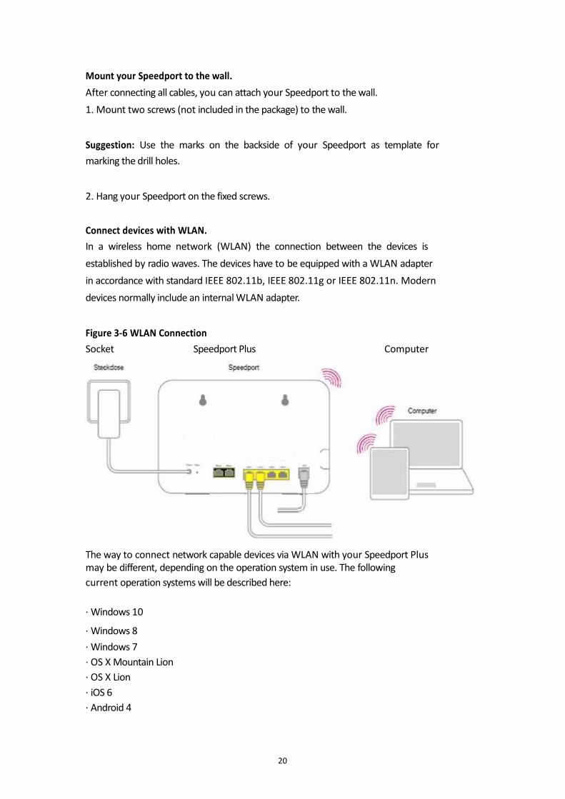
marking the drill holes. 2. Hang your Speedport on the fixed screws. Connect devices with WLAN.
In a wireless home network (WLAN) the connection between the devices is
established by radio waves. The devices have to be equipped with a WLAN adapter
in accordance with standard IEEE 802.11b, IEEE 802.11g or IEEE 802.11n. Modern
devices normally include an internal WLAN adapter. Figure 3-6 WLAN Connection
Socket Speedport Plus Computer
OTE SpeedportW724vTypeCi
The way to connect network capable devices via WLAN with your Speedport Plus may be different, depending on the operation system in use. The following
current operation systems will be described here:
· Windows 10
· Windows 8
· Windows 7
· OS X Mountain Lion
· OS X Lion
· iOS 6
· Android 4
20
For connection of your network capable devices via WLAN to your Speedport, the
WLAN function on Speedport and on the devices has to be activated.
Suggestion: Activate the WLAN function of your Speedport by pushing the WLAN
button (less than five seconds) on the front side of your Speedport; the display
WLAN has to be illuminated. WPS function is activated by pressing the WLAN button
for more than five seconds.
Connect Windows 8 via WLAN.
If you have Windows 8 installed in your device, please carry out the following steps:
1. Open the Charms-Bar.
2. Click on Settings.
3. Click on the WLAN symbol.
4. Click on the WLAN name (SSID) of your Speedport. Suggestion: In its delivery status the WLAN name (SSID) is the same as the one
printed on the back side label of your Speedport device. 5 Click on Connecting.
6. Key in the WLAN key of your Speedport in the entry field. Suggestion: In its delivery status the WLAN key is printed on the back side label of
your Speedport device. 7. Click on Forward.
8. Choose between public networks and home or business networks.
21
Connect Windows 7 via WLAN.
If you use the operation system Windows 7 on your device, please carry out the
following steps:
1. Click in the start menu on the remark system operation.
2. Click on the remark network and internet.
3. Click under the submenu centre for network and clearance on establish
connection to a network.
4. Click on the WLAN name (SSID) of your Speedport. Suggestion: In its delivery status the WLAN name (SSID) is the same as the one
printed on the back side label of your Speedport device. 5. Click on establish connection.
6. Enter the WLAN key of your Speedport into the entry field. Suggestion: In its delivery status the WLAN key is printed on the back side label of
your Speedport device. 7. Click on Connecting.
8. Choose between public network and home or business network.
22
Connect OS X Mountain Lion / Lion via WLAN.
If you use the operation system OS X Mountain Lion or OS X Lion on your device,
please carry out the following steps:
1. Click on the WLAN symbol in the menu bar.
2. Click on the statement activate WLAN.
3. Click on the WLAN name (SSID) of your Speedport. Suggestion: In its delivery status the WLAN name (SSID) is the same as the one
printed on the back side label of your Speedport device. 4. Enter the WLAN key of your Speedport in the entry field. Suggestion: In its delivery status the WLAN key is printed on the back side label of
your Speedport device. Connect iOS 6 via WLAN.
If you use the operating system iOS 6 on your device, please carry out the following
steps:
1. Click on icon Settings.
2. Click on the entry WLAN.
3. Activate the WLAN function.
4. Click on the WLAN name (SSID) of your Speedport. Suggestion: In its delivery status the WLAN name (SSID) is the same as the one
printed on the back side label of your Speedport device. 5. Key in the WLAN key of your Speedport in the input box. Suggestion: In its delivery status the WLAN key is printed on the back side label of
your Speedport device. 6. Click on Connecting. Connect Android 4 via WLAN.
If you use the operation system Android 4 on your device, please carry out the
following steps:
1. Tip on the icon Settings.
2. Tip on the statement WLAN.
23

3. Activate the WLAN function.
4. Tip on the WLAN name (SSID) of your Speedport. Suggestion: In its delivery status the WLAN name (SSID) is the same as the one
printed on the back side label of your Speedport device. 5. Enter the WLAN key of your Speedport in the entry field. Suggestion: In its delivery status the WLAN key is printed on the back side label of
your Speedport device. 6. Tip on Connecting.
24
Install your Speedport.
With your Speedport all your connected computer and network capable devices can
access the internet at the same time.
Therefore, internet access data and internet telephony access data (VoIP)
parameters have to be entered in Speedport’s configuration application.
The configuration application of Speedport is a user interface based on an internet
browser.
For the first installation of your Speedport you will be lead through the
configuration. For that you will receive detailed information about the steps, which
are to be carried out. Suggestion: We suggest using the automatic configuration. Use the internet browser, which has been installed on your device. The procedure is identical for all internet browsers. For example we suggest the
Microsoft Internet Explorer version 9.0 or above, Mozilla Firefox starting from
version 13 or Safari. Requirements for configuration.
· You have installed your Speedport and checked the network configuration of your
PC/Laptop/Mac.
· The network capable device has established a connection with Speedport (through
WLAN or LAN).
25
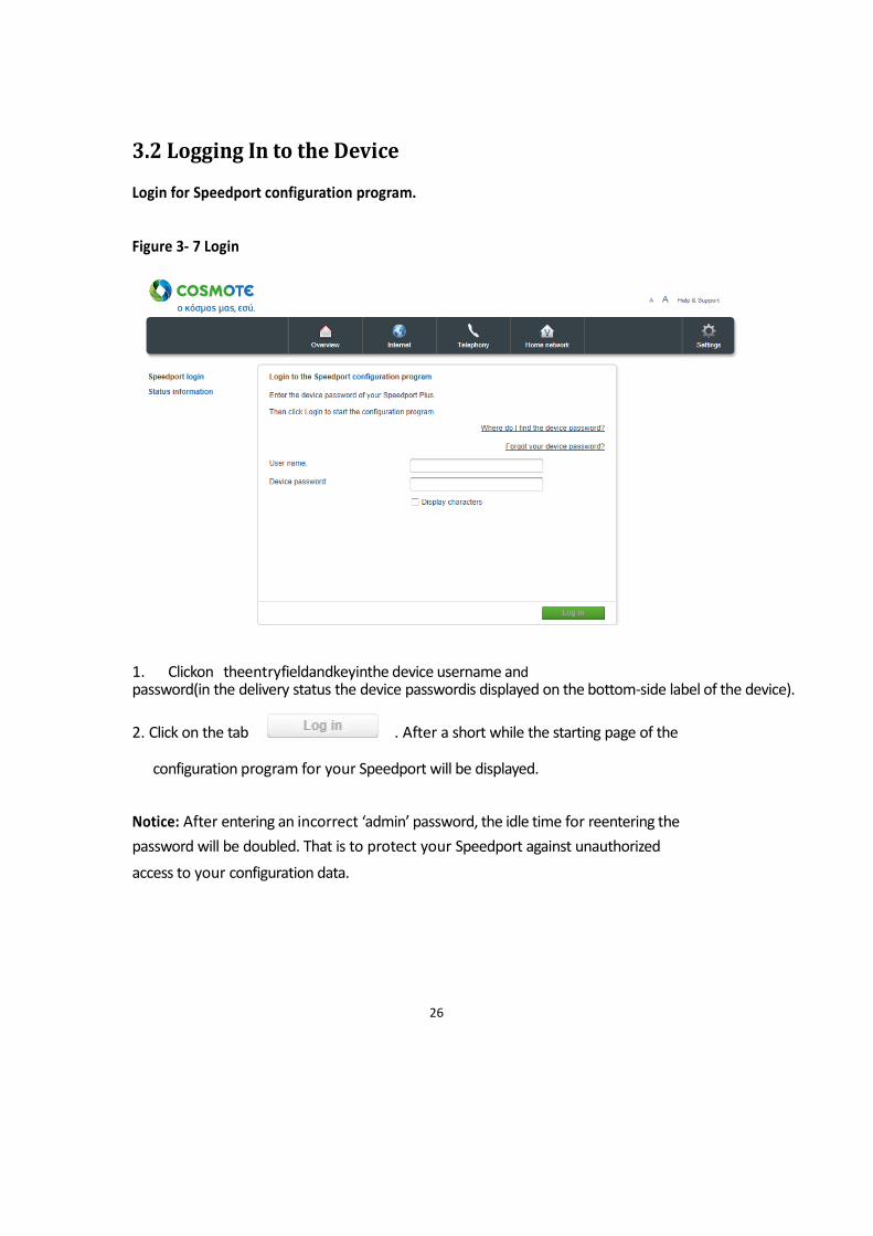
3.2 Logging In to the Device
Login for Speedport configuration program. Figure 3- 7 Login
1. Clickon theentryfieldandkeyinthe device username and password(in the delivery status the device passwordis displayed on the bottom-side label of the device).
2. Click on the tab . After a short while the starting page of the
configuration program for your Speedport will be displayed.
Notice: After entering an incorrect ‘admin’ password, the idle time for reentering the
password will be doubled. That is to protect your Speedport against unauthorized
access to your configuration data.
26
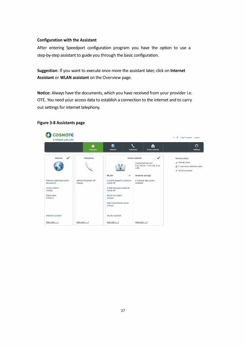
Configuration with the Assistant
After entering Speedport configuration program you have the option to use a
step-by-step assistant to guide you through the basic configuration. Suggestion: If you want to execute once more the assistant later, click on Internet
Assistant or WLAN assistant on the Overview page. Notice: Always have the documents, which you have received from your provider i.e.
OTE. You need your access data to establish a connection to the internet and to carry
out settings for internet telephony. Figure 3-8 Assistants page
27
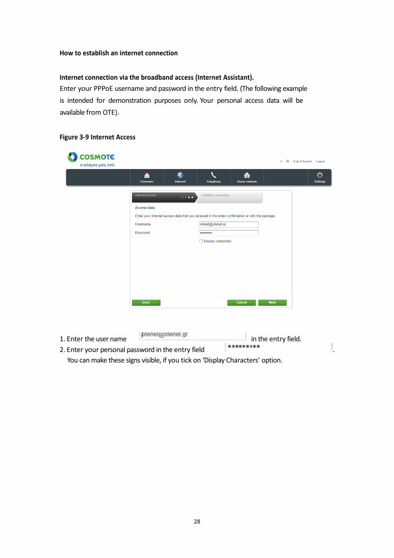
How to establish an internet connection Internet connection via the broadband access (Internet Assistant).
Enter your PPPoE username and password in the entry field. (The following example
is intended for demonstration purposes only. Your personal access data will be
available from OTE). Figure 3-9 Internet Access
1. Enter the user name in the entry field.
2. Enter your personal password in the entry field .
You can make these signs visible, if you tick on ‘Display Characters’ option.
28
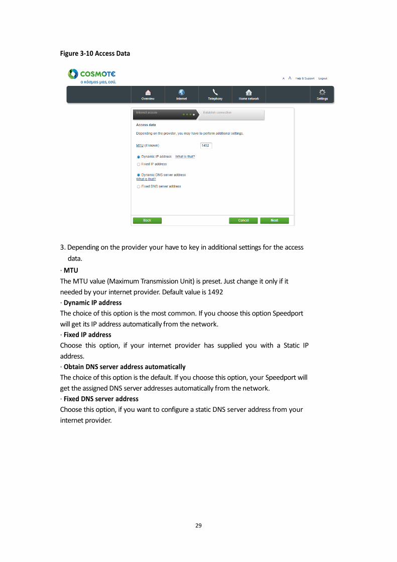
Figure 3-10 Access Data
3. Depending on the provider your have to key in additional settings for the access
data.
· MTU
The MTU value (Maximum Transmission Unit) is preset. Just change it only if it
needed by your internet provider. Default value is 1492
· Dynamic IP address
The choice of this option is the most common. If you choose this option Speedport
will get its IP address automatically from the network.
· Fixed IP address
Choose this option, if your internet provider has supplied you with a Static IP
address.
· Obtain DNS server address automatically
The choice of this option is the default. If you choose this option, your Speedport will
get the assigned DNS server addresses automatically from the network.
· Fixed DNS server address
Choose this option, if you want to configure a static DNS server address from your
internet provider.
29
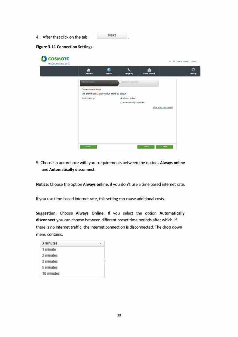
4. After that click on the tab . Figure 3-11 Connection Settings
5. Choose in accordance with your requirements between the options Always online
and Automatically disconnect.
Notice: Choose the option Always online, if you don’t use a time based internet rate. If you use time-based internet rate, this setting can cause additional costs. Suggestion: Choose Always Online. If you select the option Automatically
disconnect you can choose between different preset time periods after which, if
there is no Internet traffic, the Internet connection is disconnected. The drop down
menu contains:
.
30
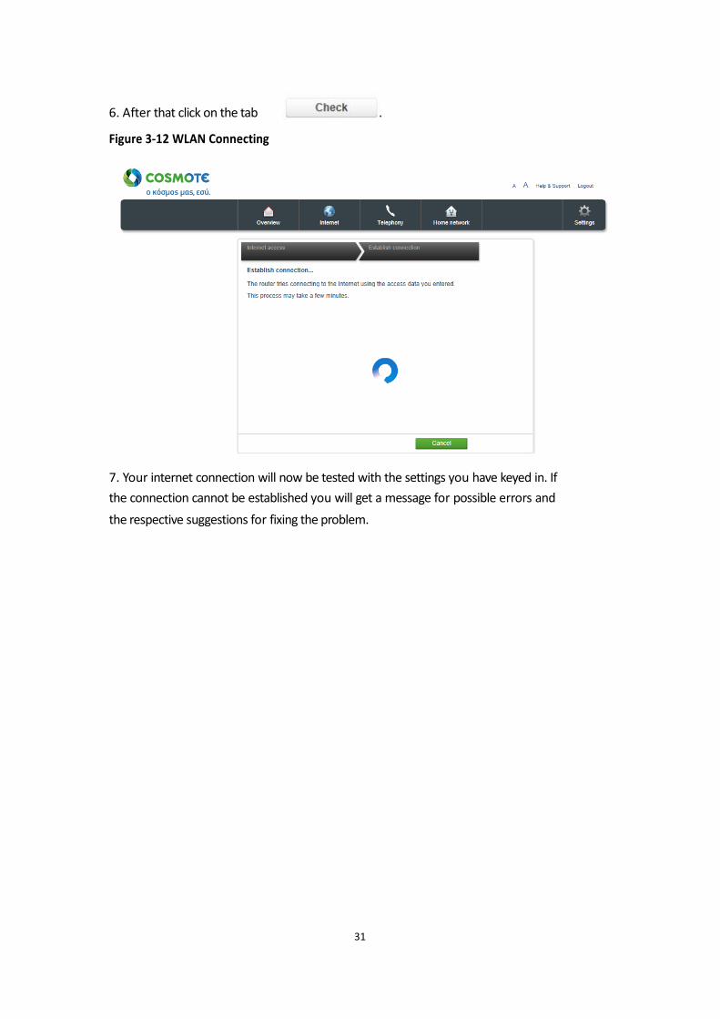
6. After that click on the tab .
Figure 3-12 WLAN Connecting
7. Your internet connection will now be tested with the settings you have keyed in. If
the connection cannot be established you will get a message for possible errors and
the respective suggestions for fixing the problem.
31
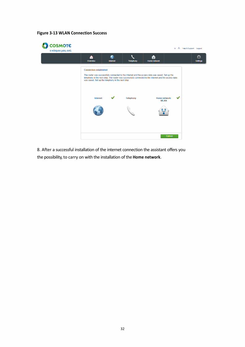
Figure 3-13 WLAN Connection Success
8. After a successful installation of the internet connection the assistant offers you
the possibility, to carry on with the installation of the Home network.
32
Establish home network (WLAN).
With your Speedport you can establish a home network via WLAN (Wireless Local
Area Network). For this home network all connections are built up wirelessly.
The wireless connection is carried out irrespective of the operation system. But for
every network capable device, which you want to connect to your Speedport via
WLAN you need a Wi-Fi compatible network capable card.
In modern computers, notebooks and other network capable devices, a WLAN
adapter is already integrated. For more information of the integrated WLAN adapter
in your device, please consult the documentation of the manufacturer.
The home network for your Wi-Fi network capable devices will be recognized via a
distinct WLAN name (SSID or also network name). This distinct WLAN name will be
sent by your Speedport.
Before starting with the connection procedure, please check, if the network capable
device, with which you want to establish the wireless connection, does support the
WPA2 encryption. You can learn this from the respective instruction manual. Suggestion: We suggest using WLAN network components, which support a secure
WPA2 encryption.
33
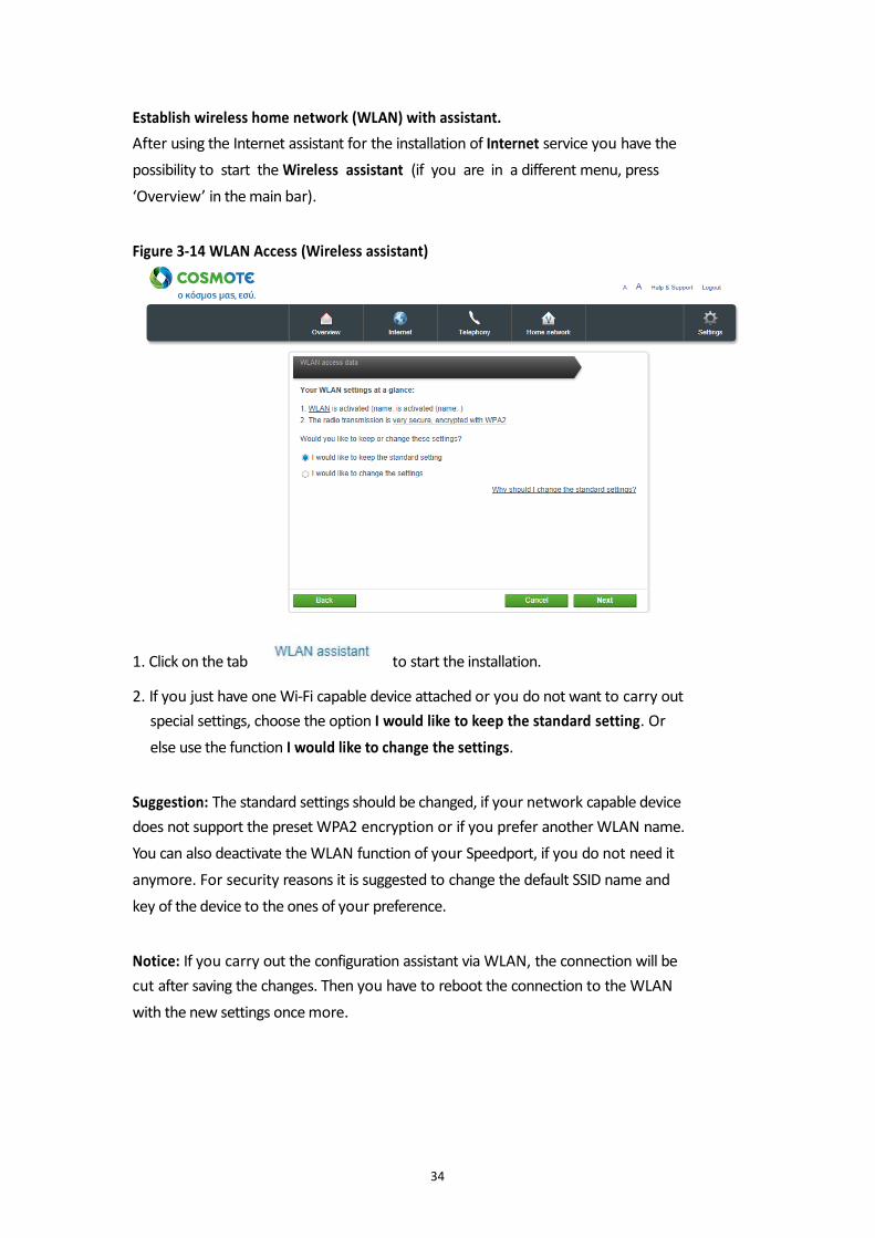
Establish wireless home network (WLAN) with assistant.
After using the Internet assistant for the installation of Internet service you have the
possibility to start the Wireless assistant (if you are in a different menu, press
‘Overview’ in the main bar). Figure 3-14 WLAN Access (Wireless assistant)
1. Click on the tab to start the installation. 2. If you just have one Wi-Fi capable device attached or you do not want to carry out
special settings, choose the option I would like to keep the standard setting. Or
else use the function I would like to change the settings.
Suggestion: The standard settings should be changed, if your network capable device
does not support the preset WPA2 encryption or if you prefer another WLAN name.
You can also deactivate the WLAN function of your Speedport, if you do not need it
anymore. For security reasons it is suggested to change the default SSID name and
key of the device to the ones of your preference. Notice: If you carry out the configuration assistant via WLAN, the connection will be
cut after saving the changes. Then you have to reboot the connection to the WLAN
with the new settings once more.
34
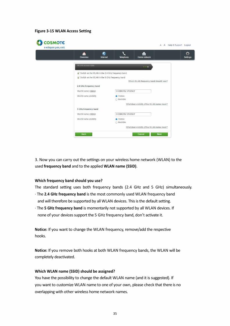
Figure 3-15 WLAN Access Setting
3. Now you can carry out the settings on your wireless home network (WLAN) to the
used frequency band and to the applied WLAN name (SSID). Which frequency band should you use?
The standard setting uses both frequency bands (2.4 GHz and 5 GHz) simultaneously.
· The 2.4 GHz frequency band is the most commonly used WLAN frequency band
and will therefore be supported by all WLAN devices. This is the default setting.
· The 5 GHz frequency band is momentarily not supported by all WLAN devices. If
none of your devices support the 5 GHz frequency band, don’t activate it.
Notice: If you want to change the WLAN frequency, remove/add the respective
hooks. Notice: If you remove both hooks at both WLAN frequency bands, the WLAN will be
completely deactivated. Which WLAN name (SSID) should be assigned?
You have the possibility to change the default WLAN name (and it is suggested). If
you want to customize WLAN name to one of your own, please check that there is no
overlapping with other wireless home network names.
35
· With the individually modified WLAN name (SSID) you can easily recognize your
own wireless home network among other wireless home networks.
·EnteryourindividualWLANname(SSID)intheentryfield.
Notice: The WLAN name (SSID) can be up to 32 signs long and consist of signs,
numbers or special signs. But please avoid personal info embedded in the name such
as e-mail addresses, birthdays, names, telephone numbers or addresses. Suggestion: If you assign different WLAN names (SSID), you can distinguish them
better when installing Wi-Fi capable network devices. What does the visibility of the WLAN name mean?
If you do not want your wireless home network (WLAN) to be seen by others you can
deactivate the visibility of your network.
· The option visible makes it easier for your wireless home networks (WLAN) to be
found and chosen by new network capable device for installation.
· The option invisible slightly increases the protection against unauthorized access,
but does not replace at all an encryption of the wireless home network (WLAN). If
you choose this option then you have to manually add the configured SSID name of
Speedport to the Wi-Fi capable device.
4. If you have finished configuring the settings according to your requirements, click
on the tab .
36

Figure 3-16 WLAN Encryption
5. Now you can carry on with the encryption settings of your wireless home network
(WLAN).
Which encryption shall you use?
You have the possibility to change the preset encryption. This might be necessary if
you want to build up a wireless home network with older network capable devices.
The secure WPA2 encryption is the default setting. Notice: The set encryption is valid for both frequency bands. Suggestion: The supported encryption of your WLAN network capable devices can
be learned form their respective instruction manuals. Which WLAN key you should choose?
If you want to change the WLAN key, pleaseenter your personal WLAN key in the
entry field.
Choose a WLAN key consisting of at least eight and at most 63 signs. Do not insert
empty spaces. The longer the WLAN key the more secure it is. But please avoid
embedding personal information such as birthdays, names, telephone numbers and
addresses.
37

Notice: Assign personal and secure password! Especially for the device password of
your Speedport, the internet access password (PPPoE) and the WLAN key. Suggestion: The WLAN key has to be inserted at every WLAN network capable
device, which you want to connect with the Speedport through WLAN.
6. Click on the tab .
7. The configuration of your Wireless home network (WLAN) is now finished. Click on
the tab to close your assistant.
38
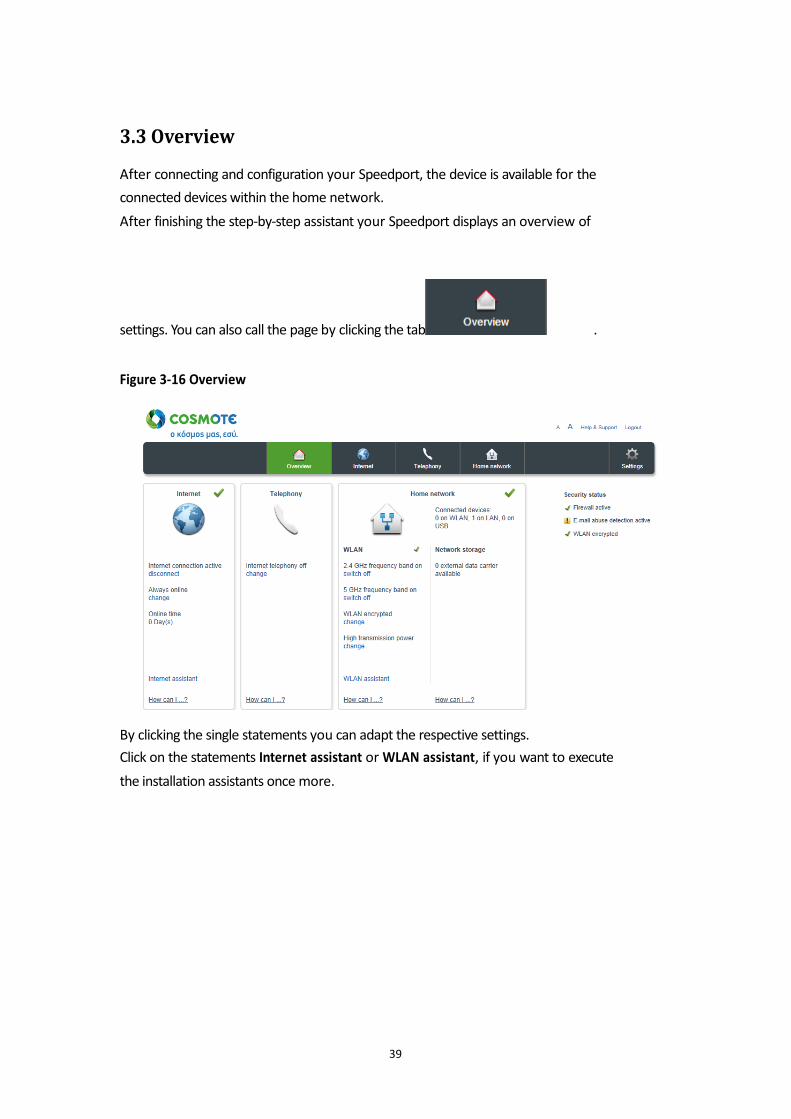
3.3 Overview
After connecting and configuration your Speedport, the device is available for the
connected devices within the home network.
After finishing the step-by-step assistant your Speedport displays an overview of
settings. You can also call the page by clicking the tab . Figure 3-16 Overview
By clicking the single statements you can adapt the respective settings.
Click on the statements Internet assistant or WLAN assistant, if you want to execute
the installation assistants once more.
39
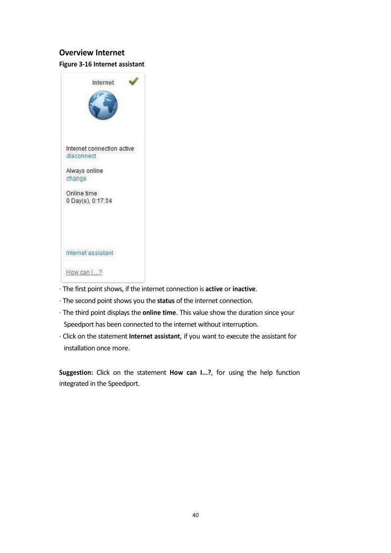
Overview Internet
Figure 3-16 Internet assistant
· The first point shows, if the internet connection is active or inactive.
· The second point shows you the status of the internet connection.
· The third point displays the online time. This value show the duration since your
Speedport has been connected to the internet without interruption.
· Click on the statement Internet assistant, if you want to execute the assistant for
installation once more.
Suggestion: Click on the statement How can I...?, for using the help function
integrated in the Speedport.
40
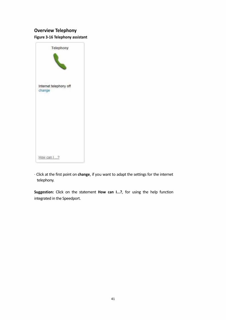
Overview Telephony
Figure 3-16 Telephony assistant · Click at the first point on change, if you want to adapt the settings for the internet
telephony.
Suggestion: Click on the statement How can I...?, for using the help function
integrated in the Speedport.
41
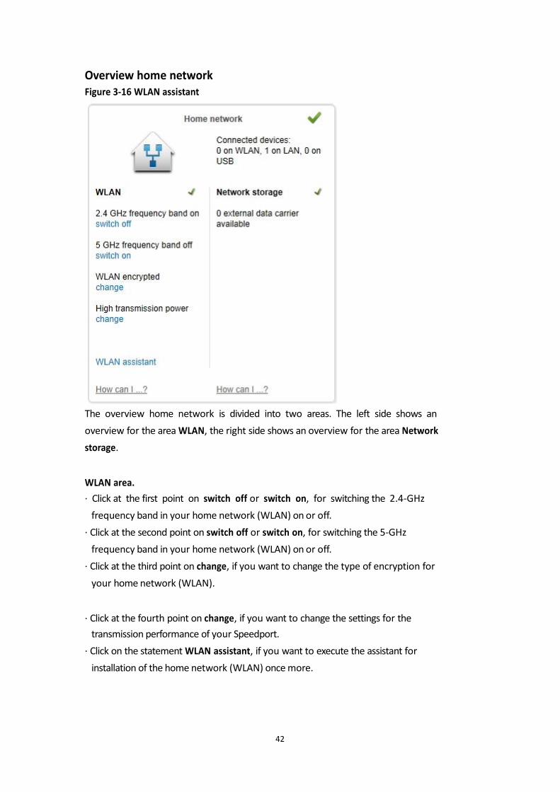
Overview home network
Figure 3-16 WLAN assistant
The overview home network is divided into two areas. The left side shows an
overview for the area WLAN, the right side shows an overview for the area Network
storage. WLAN area.
· Click at the first point on switch off or switch on, for switching the 2.4-GHz
frequency band in your home network (WLAN) on or off.
· Click at the second point on switch off or switch on, for switching the 5-GHz
frequency band in your home network (WLAN) on or off.
· Click at the third point on change, if you want to change the type of encryption for
your home network (WLAN).
· Click at the fourth point on change, if you want to change the settings for the
transmission performance of your Speedport.
· Click on the statement WLAN assistant, if you want to execute the assistant for
installation of the home network (WLAN) once more.
42

Area Network storage.
· The first point shows how many external data storages (USB sticks, hard drives)
you have attached to the USB ports of your Speedport.
Suggestion: Click on the statement How can I...?, for using the help function
integrated in the Speedport.
43
Chapter 4 Status
4.1 System Information
4.1.1 Version numbers and DSL information
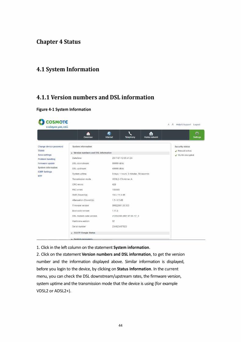
Figure 4-1 System Information
1. Click in the left column on the statement System information.
2. Click on the statement Version numbers and DSL information, to get the version
number and the information displayed above. Similar information is displayed,
before you login to the device, by clicking on Status Information. In the current
menu, you can check the DSL downstream/upstream rates, the firmware version,
system uptime and the transmission mode that the device is using (for example
VDSL2 or ADSL2+).
44
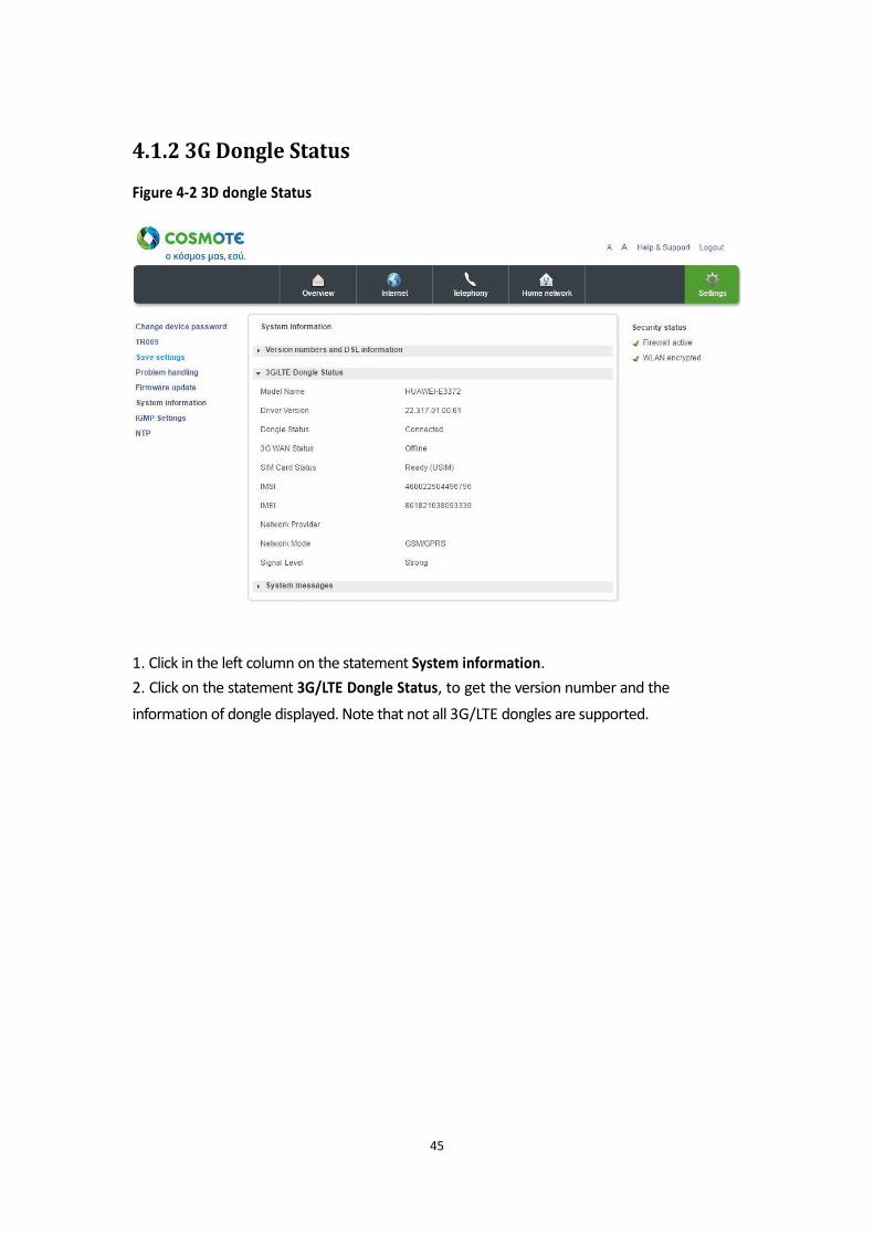
4.1.2 3G Dongle Status
Figure 4-2 3D dongle Status
1. Click in the left column on the statement System information.
2. Click on the statement 3G/LTE Dongle Status, to get the version number and the
information of dongle displayed. Note that not all 3G/LTE dongles are supported.
45
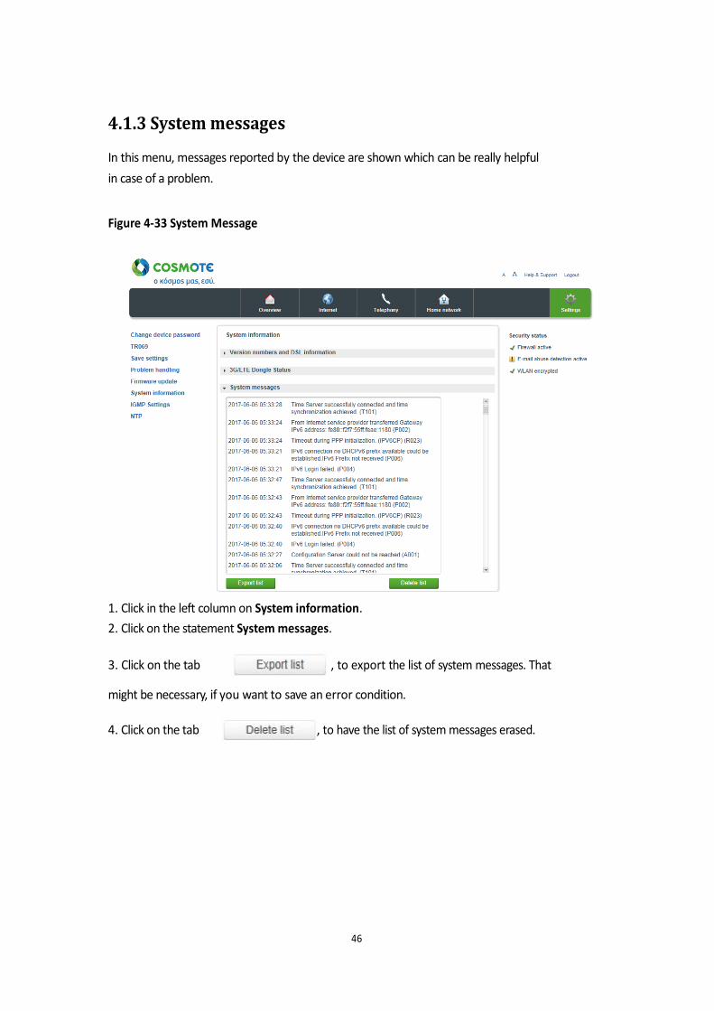
4.1.3 System messages
In this menu, messages reported by the device are shown which can be really helpful
in case of a problem. Figure 4-33 System Message
1. Click in the left column on System information.
2. Click on the statement System messages.
3. Click on the tab
, to export the list of system messages. That
might be necessary, if you want to save an error condition.
4. Click on the tab
, to have the list of system messages erased.
46
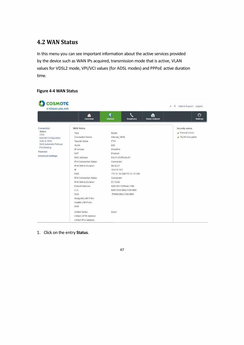
4.2 WAN Status
In this menu you can see important information about the active services provided
by the device such as WAN IPs acquired, transmission mode that is active, VLAN
values for VDSL2 mode, VPI/VCI values (for ADSL modes) and PPPoE active duration
time. Figure 4-4 WAN Status
1. Click on the entry Status.
47
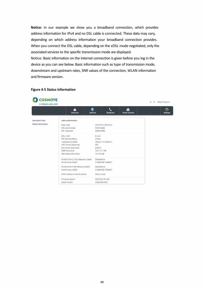
Notice: In our example we show you a broadband connection, which provides
address information for IPv4 and no DSL cable is connected. These data may vary,
depending on which address information your broadband connection provides.
When you connect the DSL cable, depending on the xDSL mode negotiated, only the
associated services to the specific transmission mode are displayed.
Notice: Basic information on the Internet connection is given before you log in the
device as you can see below. Basic information such as type of transmission mode,
downstream and upstream rates, SNR values of the connection, WLAN information
and firmware version. Figure 4-5 Status Information
48
Chapter 5 Internet Menu
5.1Connection option
5.1.1Status
Described in chapter 4.2.
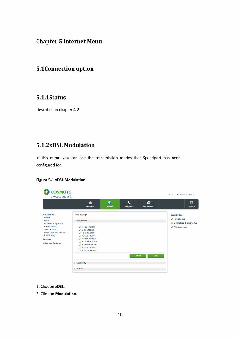
5.1.2xDSL Modulation
In this menu you can see the transmission modes that Speedport has been
configured for. Figure 5-1 xDSL Modulation
1. Click on xDSL.
2. Click on Modulation.
49
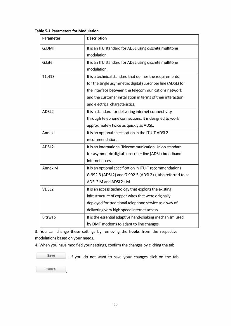
Table 5-1 Parameters for Modulation 3. You can change these settings by removing the hooks from the respective
modulations based on your needs.
4. When you have modified your settings, confirm the changes by clicking the tab
. If you do not want to save your changes click on the tab
.
50
Parameter Description
G.DMT It is an ITU standard for ADSL using discrete multitone
modulation.
G.Lite It is an ITU standard for ADSL using discrete multitone
modulation.
T1.413 It is a technical standard that defines the requirements
for the single asymmetric digital subscriber line (ADSL) for
the interface between the telecommunications network
and the customer installation in terms of their interaction
and electrical characteristics.
ADSL2 It is a standard for delivering internet connectivity
through telephone connections. It is designed to work
approximately twice as quickly as ADSL.
Annex L It is an optional specification in the ITU-T ADSL2
recommendation.
ADSL2+ It is an International Telecommunication Union standard
for asymmetric digital subscriber line (ADSL) broadband
Internet access.
Annex M It is an optional specification in ITU-T recommendations
G.992.3 (ADSL2) and G.992.5 (ADSL2+), also referred to as
ADSL2 M and ADSL2+ M.
VDSL2 It is an access technology that exploits the existing
infrastructure of copper wires that were originally
deployed for traditional telephone service as a way of
delivering very high speed internet access.
Bitswap It is the essential adaptive hand-shaking mechanism used
by DMT modems to adapt to line changes.
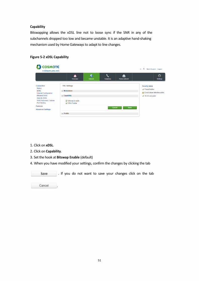
Capability
Bitswapping allows the xDSL line not to loose sync if the SNR in any of the
subchannels dropped too low and became unstable. It is an adaptive hand-shaking
mechanism used by Home Gateways to adapt to line changes. Figure 5-2 xDSL Capability
1. Click on xDSL.
2. Click on Capability.
3. Set the hook at Bitswap Enable (default)
4. When you have modified your settings, confirm the changes by clicking the tab
. If you do not want to save your changes click on the tab
.
51
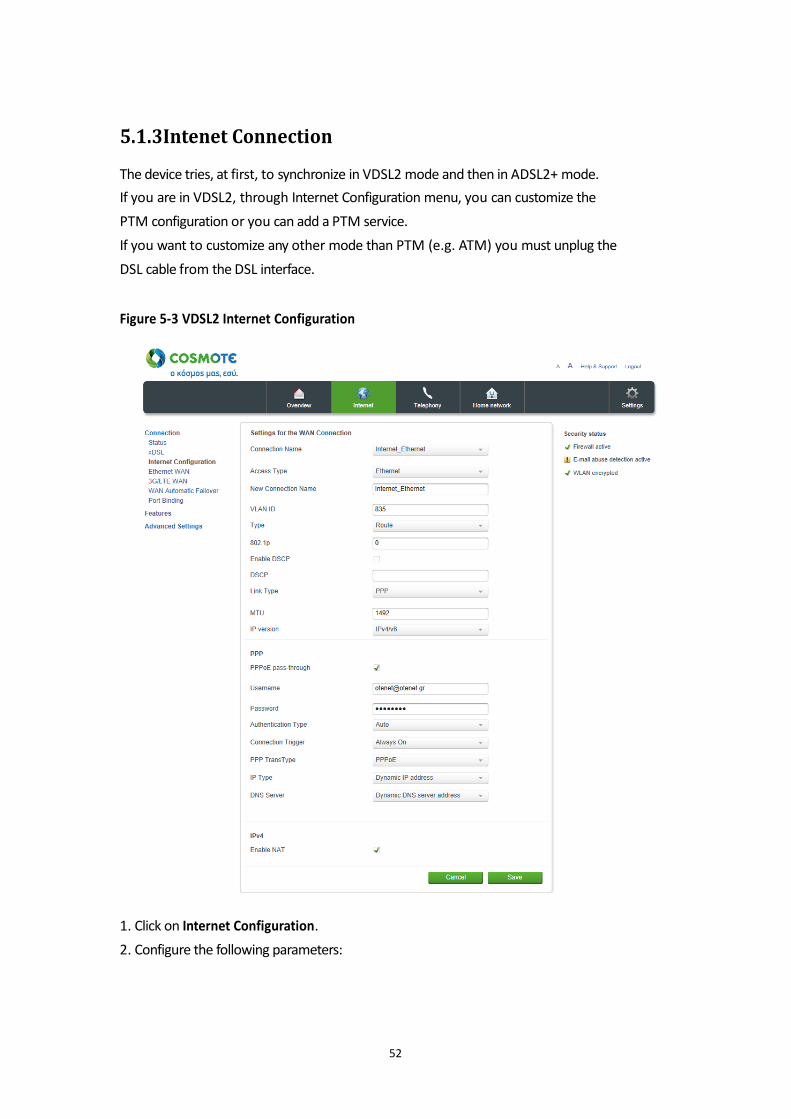
5.1.3Intenet Connection
The device tries, at first, to synchronize in VDSL2 mode and then in ADSL2+ mode.
If you are in VDSL2, through Internet Configuration menu, you can customize the
PTM configuration or you can add a PTM service.
If you want to customize any other mode than PTM (e.g. ATM) you must unplug the
DSL cable from the DSL interface. Figure 5-3 VDSL2 Internet Configuration
1. Click on Internet Configuration.
2. Configure the following parameters:
52
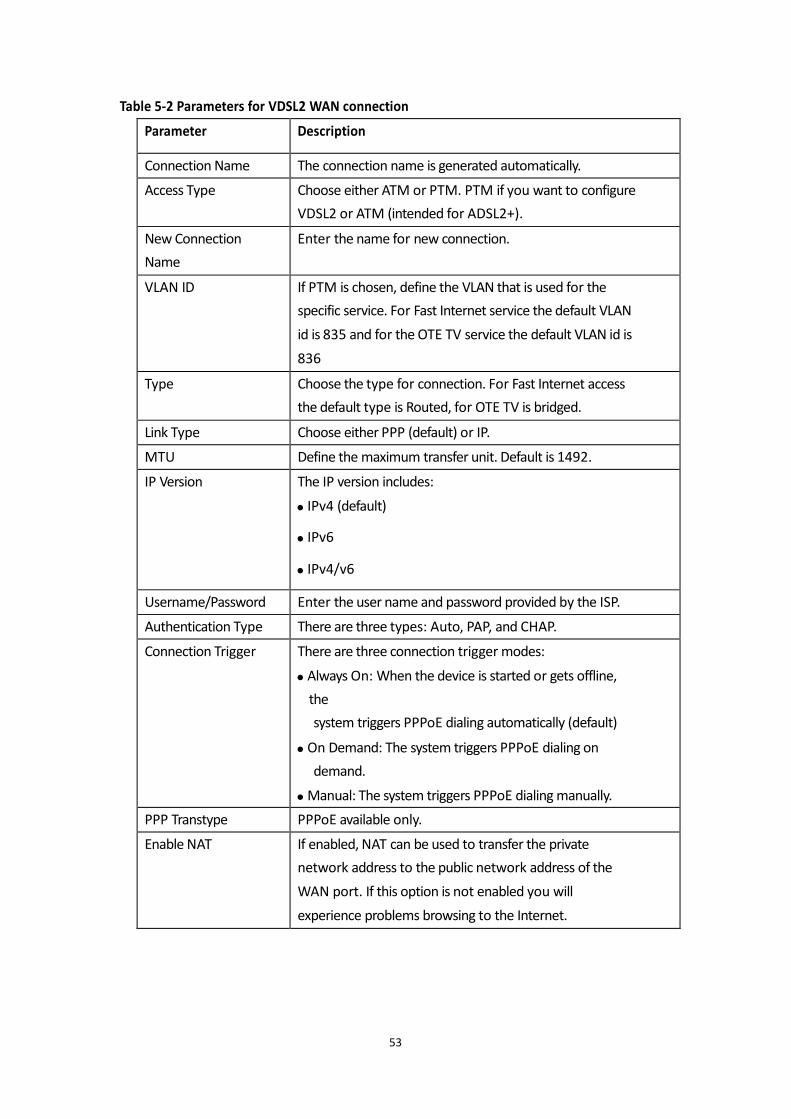
Table 5-2 Parameters for VDSL2 WAN connection
53
Parameter Description
Connection Name The connection name is generated automatically.
Access Type Choose either ATM or PTM. PTM if you want to configure
VDSL2 or ATM (intended for ADSL2+).
New Connection
Name
Enter the name for new connection.
VLAN ID If PTM is chosen, define the VLAN that is used for the
specific service. For Fast Internet service the default VLAN
id is 835 and for the OTE TV service the default VLAN id is
836
Type Choose the type for connection. For Fast Internet access
the default type is Routed, for OTE TV is bridged.
Link Type Choose either PPP (default) or IP.
MTU Define the maximum transfer unit. Default is 1492.
IP Version The IP version includes:
IPv4 (default)
IPv6
IPv4/v6
Username/Password Enter the user name and password provided by the ISP.
Authentication Type There are three types: Auto, PAP, and CHAP.
Connection Trigger There are three connection trigger modes:
Always On: When the device is started or gets offline,
the
system triggers PPPoE dialing automatically (default)
On Demand: The system triggers PPPoE dialing on
demand.
Manual: The system triggers PPPoE dialing manually.
PPP Transtype PPPoE available only.
Enable NAT If enabled, NAT can be used to transfer the private
network address to the public network address of the
WAN port. If this option is not enabled you will
experience problems browsing to the Internet.
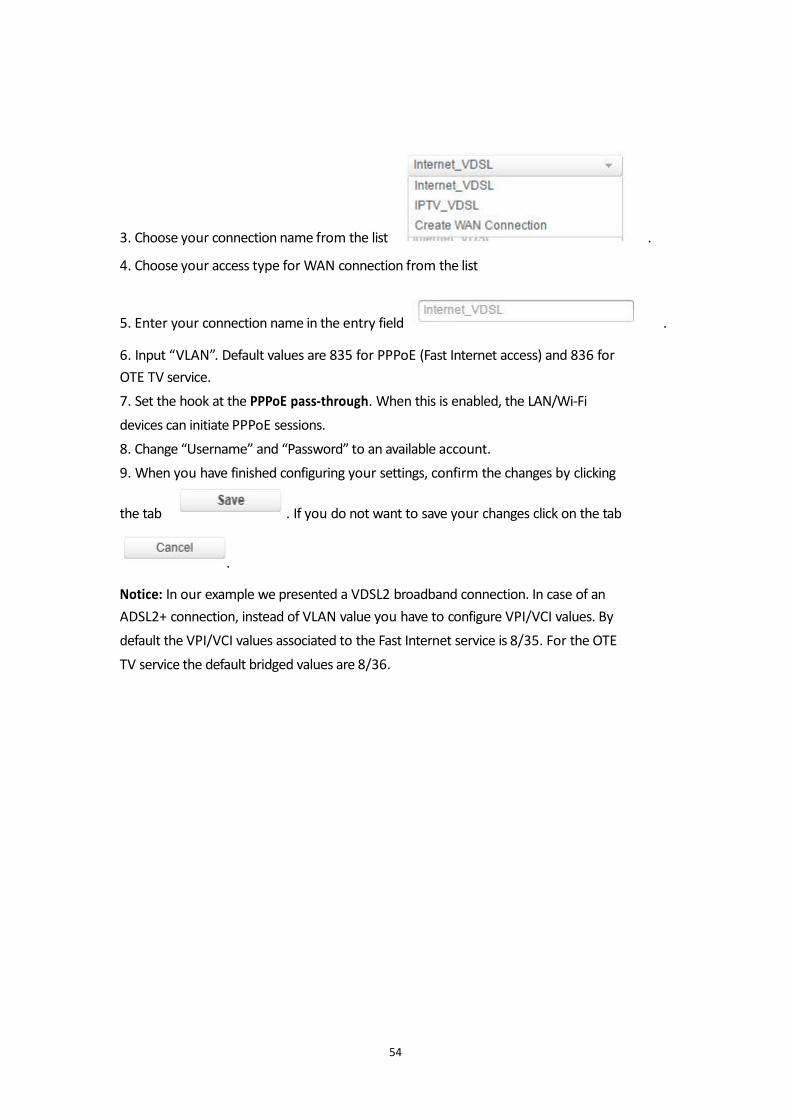
3. Choose your connection name from the list .
4. Choose your access type for WAN connection from the list
5. Enter your connection name in the entry field . 6. Input “VLAN”. Default values are 835 for PPPoE (Fast Internet access) and 836 for
OTE TV service.
7. Set the hook at the PPPoE pass-through. When this is enabled, the LAN/Wi-Fi
devices can initiate PPPoE sessions.
8. Change “Username” and “Password” to an available account.
9. When you have finished configuring your settings, confirm the changes by clicking
the tab . If you do not want to save your changes click on the tab
.
Notice: In our example we presented a VDSL2 broadband connection. In case of an
ADSL2+ connection, instead of VLAN value you have to configure VPI/VCI values. By
default the VPI/VCI values associated to the Fast Internet service is 8/35. For the OTE
TV service the default bridged values are 8/36.
54
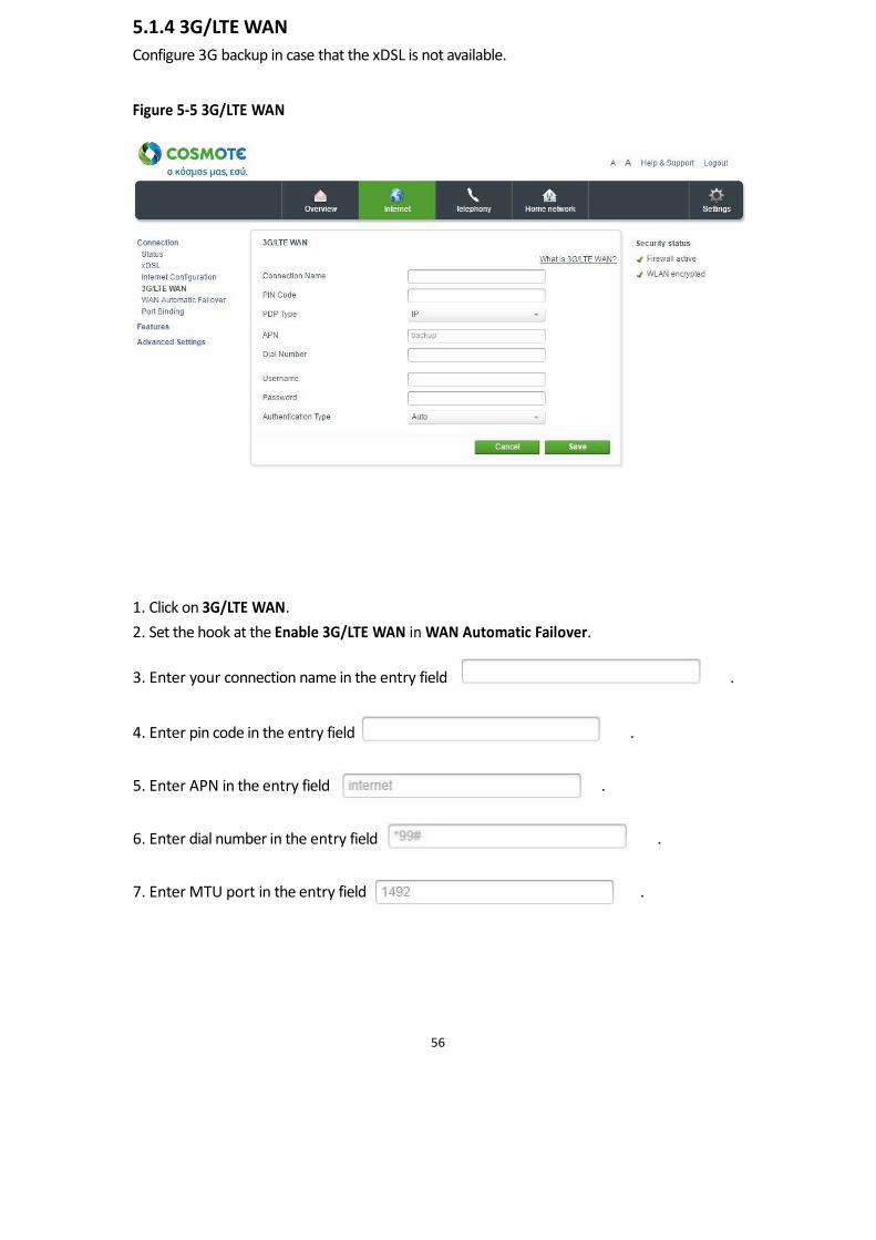
5.1.4 3G/LTE WAN
Configure 3G backup in case that the xDSL is not available. Figure 5-5 3G/LTE WAN
1. Click on 3G/LTE WAN.
2. Set the hook at the Enable 3G/LTE WAN in WAN Automatic Failover.
3. Enter your connection name in the entry field . 4. Enter pin code in the entry field . 5. Enter APN in the entry field . 6. Enter dial number in the entry field . 7. Enter MTU port in the entry field .
56
8. When you have adapted your settings, confirm the changes by clicking the tab
. If you do not want to save your changes click on the tab
.
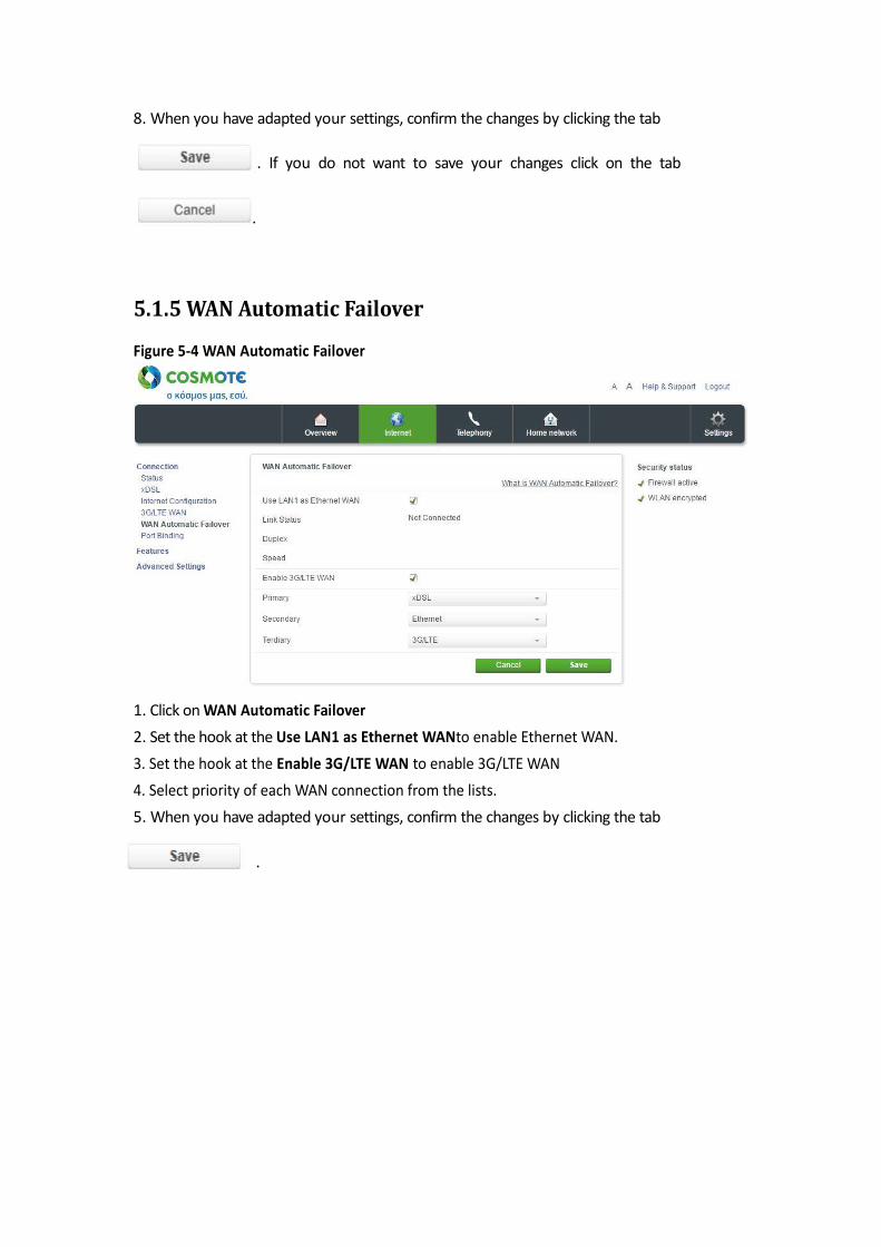
5.1.5 WAN Automatic Failover
Figure 5-4 WAN Automatic Failover
1. Click on WAN Automatic Failover
2. Set the hook at the Use LAN1 as Ethernet WANto enable Ethernet WAN.
3. Set the hook at the Enable 3G/LTE WAN to enable 3G/LTE WAN
4. Select priority of each WAN connection from the lists.
5. When you have adapted your settings, confirm the changes by clicking the tab
.
55
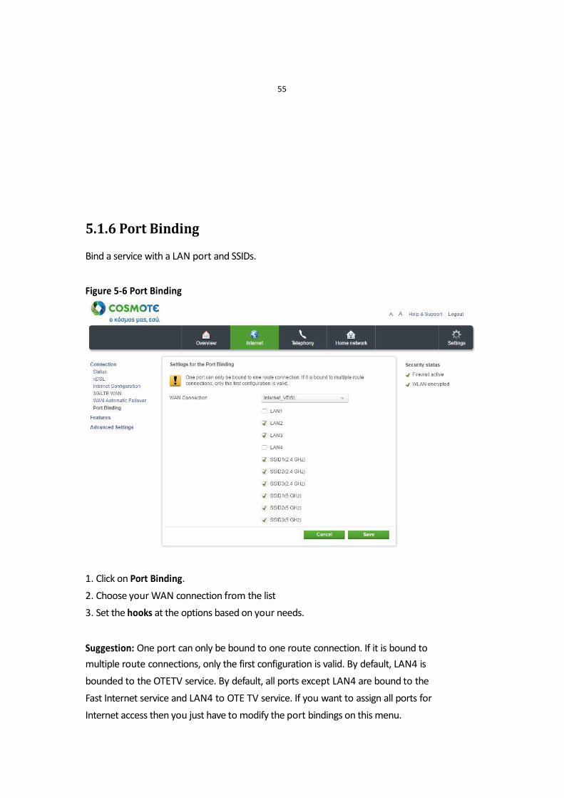
5.1.6 Port Binding
Bind a service with a LAN port and SSIDs. Figure 5-6 Port Binding
1. Click on Port Binding.
2. Choose your WAN connection from the list
3. Set the hooks at the options based on your needs. Suggestion: One port can only be bound to one route connection. If it is bound to
multiple route connections, only the first configuration is valid. By default, LAN4 is
bounded to the OTETV service. By default, all ports except LAN4 are bound to the
Fast Internet service and LAN4 to OTE TV service. If you want to assign all ports for
Internet access then you just have to modify the port bindings on this menu.

57
5.2 Features
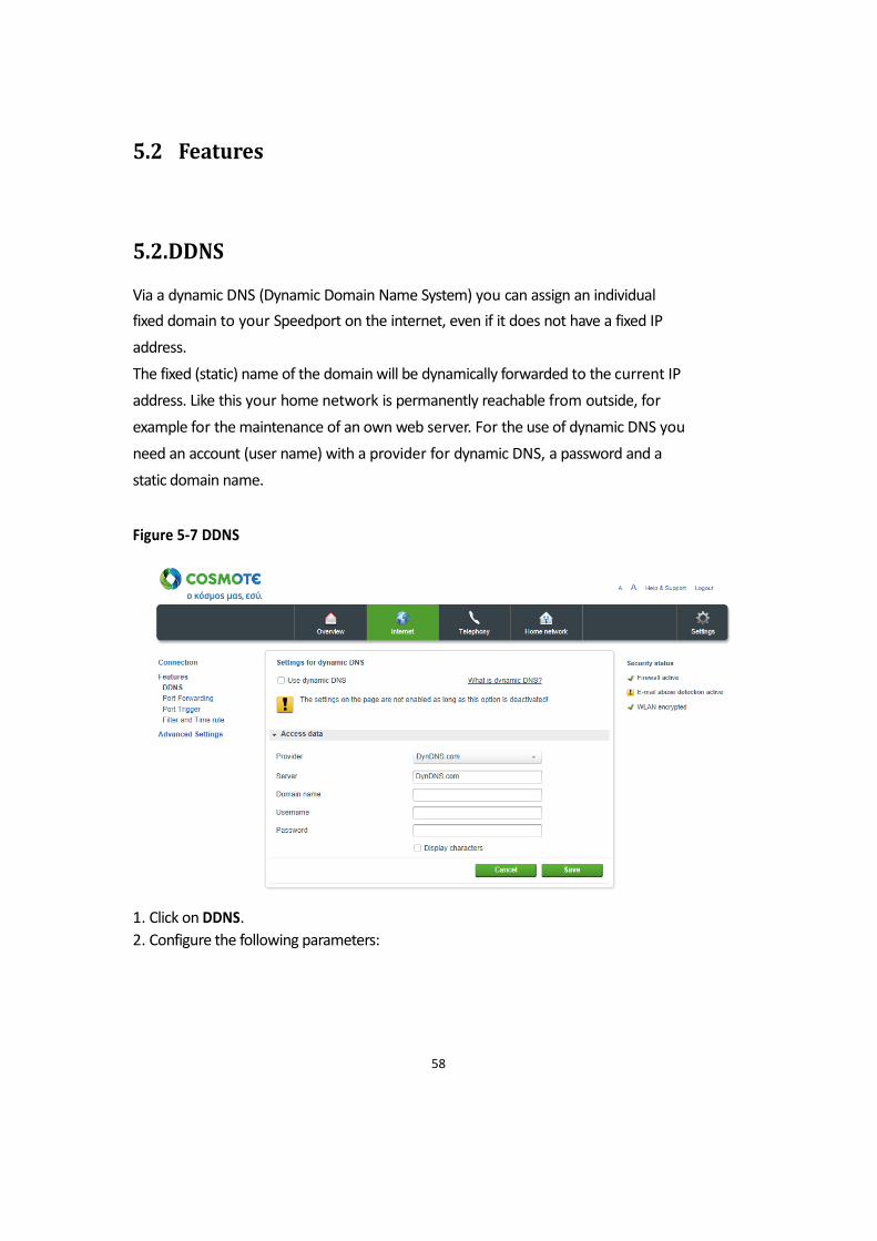
5.2.DDNS
Via a dynamic DNS (Dynamic Domain Name System) you can assign an individual
fixed domain to your Speedport on the internet, even if it does not have a fixed IP
address.
The fixed (static) name of the domain will be dynamically forwarded to the current IP
address. Like this your home network is permanently reachable from outside, for
example for the maintenance of an own web server. For the use of dynamic DNS you
need an account (user name) with a provider for dynamic DNS, a password and a
static domain name. Figure 5-7 DDNS
1. Click on DDNS.
2. Configure the following parameters:
58
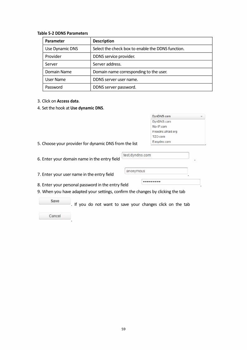
Table 5-2 DDNS Parameters
3. Click on Access data.
4. Set the hook at Use dynamic DNS. 5. Choose your provider for dynamic DNS from the list .
6. Enter your domain name in the entry field . 7. Enter your user name in the entry field . 8. Enter your personal password in the entry field .
9. When you have adapted your settings, confirm the changes by clicking the tab
. If you do not want to save your changes click on the tab
.
59
Parameter Description
Use Dynamic DNS Select the check box to enable the DDNS function.
Provider DDNS service provider.
Server Server address.
Domain Name Domain name corresponding to the user.
User Name DDNS server user name.
Password DDNS server password.
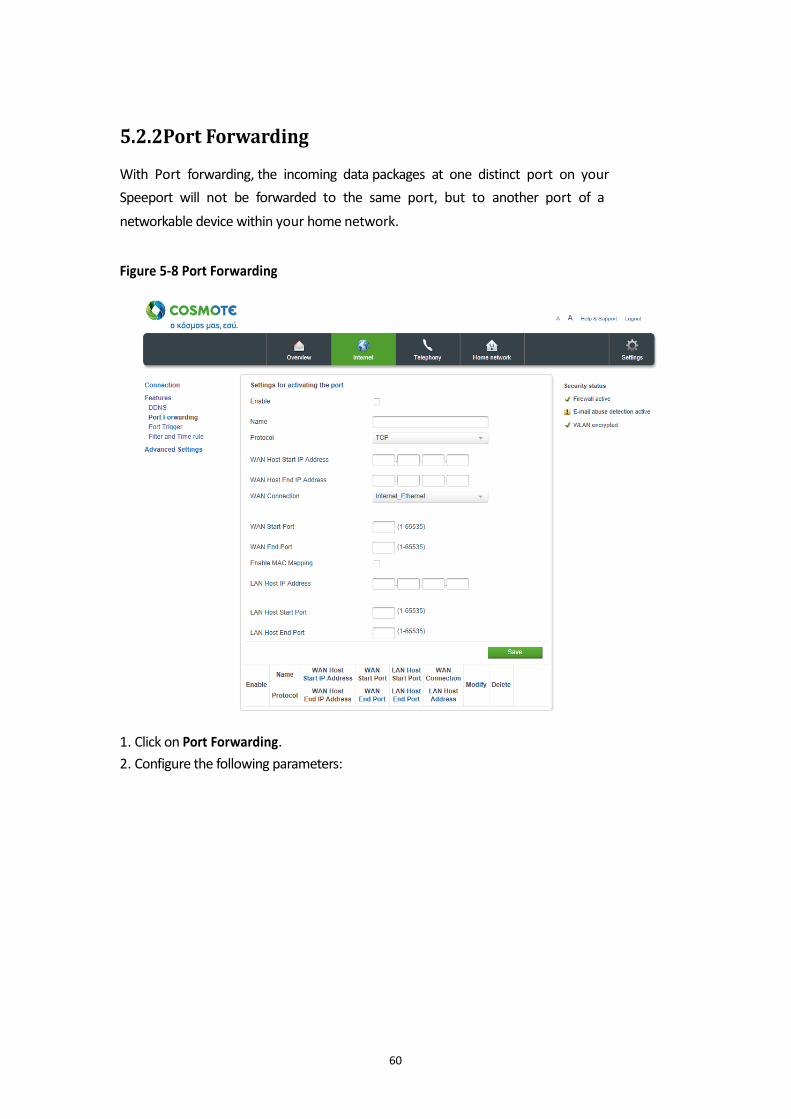
5.2.2Port Forwarding
With Port forwarding, the incoming data packages at one distinct port on your
Speeport will not be forwarded to the same port, but to another port of a
networkable device within your home network. Figure 5-8 Port Forwarding
1. Click on Port Forwarding.
2. Configure the following parameters:
60
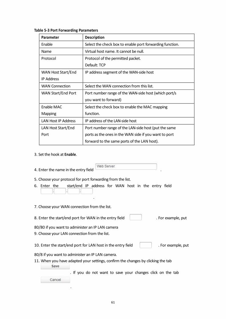
Table 5-3 Port Forwarding Parameters
3. Set the hook at Enable.
4. Enter the name in the entry field . 5. Choose your protocol for port forwarding from the list.
6. Enter the start/end IP address for WAN host in the entry field
.
7. Choose your WAN connection from the list.
8. Enter the start/end port for WAN in the entry field . For example, put 80/80 if you want to administer an IP LAN camera
9. Choose your LAN connection from the list.
10. Enter the start/end port for LAN host in the entry field . For example, put 80/8 if you want to administer an IP LAN camera.
11. When you have adapted your settings, confirm the changes by clicking the tab
. If you do not want to save your changes click on the tab
.
61
Parameter Description
Enable Select the check box to enable port forwarding function.
Name Virtual host name. It cannot be null.
Protocol Protocol of the permitted packet.
Default: TCP
WAN Host Start/End
IP Address
IP address segment of the WAN-side host
WAN Connection Select the WAN connection from this list.
WAN Start/End Port Port number range of the WAN-side host (which port/s
you want to forward)
Enable MAC
Mapping
Select the check box to enable the MAC mapping
function.
LAN Host IP Address IP address of the LAN-side host
LAN Host Start/End
Port
Port number range of the LAN-side host (put the same
ports as the ones in the WAN side if you want to port
forward to the same ports of the LAN host).
5.2.3Port Trigger
Dynamic port activation.
With a dynamic port activation you can preset, which ports of an application (i.e.
Filesharing-Programm) can be used for data exchange.
The dynamic port activation functions similarly to port forwarding. But you do not
yet define the rules, to which networkable device incoming data packages for a
certain port are forwarded.
Instead you define a port for outgoing data packages, which serves as trigger for the
forwarding to a (mostly different) port.
As soon as an outgoing data package passes the Speedport on the before preset
triggering port (trigger), then usually the rule for defined port forwarding will get
active. For that incoming data packages will be forwarded to the networkable
devices in the home network, from which the outgoing data package originates. Notice: Please note that the data traffic via cleared ports can’t be controlled by the
firewall of your Speedport. Please also use firewall software on the respective
networkable device.
62
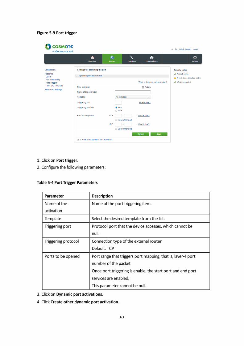
Figure 5-9 Port trigger
1. Click on Port trigger.
2. Configure the following parameters: Table 5-4 Port Trigger Parameters
3. Click on Dynamic port activations.
4. Click Create other dynamic port activation.
63
Parameter Description
Name of the
activation
Name of the port triggering item.
Template Select the desired template from the list.
Triggering port Protocol port that the device accesses, which cannot be
null.
Triggering protocol Connection type of the external router
Default: TCP
Ports to be opened Port range that triggers port mapping, that is, layer-4 port
number of the packet
Once port triggering is enable, the start port and end port
services are enabled.
This parameter cannot be null.
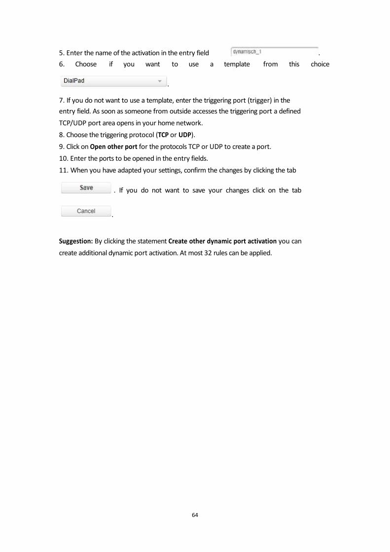
5. Enter the name of the activation in the entry field .
6. Choose if you want to use a template from this choice
.
7. If you do not want to use a template, enter the triggering port (trigger) in the
entry field. As soon as someone from outside accesses the triggering port a defined
TCP/UDP port area opens in your home network.
8. Choose the triggering protocol (TCP or UDP).
9. Click on Open other port for the protocols TCP or UDP to create a port.
10. Enter the ports to be opened in the entry fields.
11. When you have adapted your settings, confirm the changes by clicking the tab
. If you do not want to save your changes click on the tab
.
Suggestion: By clicking the statement Create other dynamic port activation you can
create additional dynamic port activation. At most 32 rules can be applied.
64

5.2.4Filter and Time Rule
Time rules
In this submenu you can set time frames, in which just some chosen devices may use
the internet. The function offers the possibility of a device individual time frame for
internet use. Outside of this time frame these devices cannot build up a connection
to the internet. Figure 5-10a Time rules
1. Click on Filter and Time rule.
2. Click on Timer rules.
3. Set the hook at the new timer rule.
4. Enter a name for the timer rule in the entry field .
5. Define the time frame (Daily or By weekday), for which the internet connection is
allowed.
6. If the internet connection is allowed daily at the same time enter the time frame
after the statement daily.
65
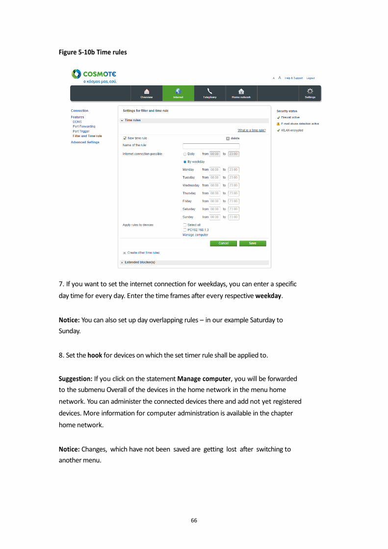
Figure 5-10b Time rules
7. If you want to set the internet connection for weekdays, you can enter a specific
day time for every day. Enter the time frames after every respective weekday. Notice: You can also set up day overlapping rules – in our example Saturday to
Sunday. 8. Set the hook for devices on which the set timer rule shall be applied to. Suggestion: If you click on the statement Manage computer, you will be forwarded
to the submenu Overall of the devices in the home network in the menu home
network. You can administer the connected devices there and add not yet registered
devices. More information for computer administration is available in the chapter
home network. Notice: Changes, which have not been saved are getting lost after switching to
another menu.
66
9. When you have adapted your settings, confirm the changes by clicking the tab
. If you do not want to save your changes click on the tab
.
Suggestion: By clicking the statement Set up new timer rule you can set up new
time rules. Notice: When the timer rule is active the effected devices cannot build up a new
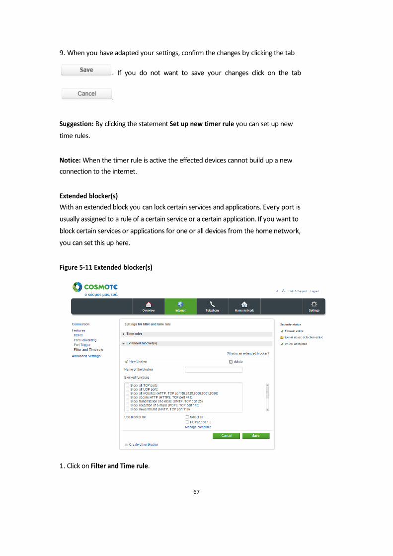
connection to the internet. Extended blocker(s)
With an extended block you can lock certain services and applications. Every port is
usually assigned to a rule of a certain service or a certain application. If you want to
block certain services or applications for one or all devices from the home network,
you can set this up here. Figure 5-11 Extended blocker(s)
1. Click on Filter and Time rule.
67
2. Click on the entry Extended blocker(s).
3. Set the hook at new blocker.
4. Enter the name for a new blocker in the entry field .
5. Set the hook for the registered blocks, which you want to activate.
6. Set the hook for devices, on which the set locks shall be applied to. Suggestion: If you click on the statement Manage computer, you will be forwarded
to the submenu Overall of the devices in the home network in the menu home
network. You can administer the connected devices there and add not yet registered
devices. More information for computer administration is available in the chapter
home network. Notice: Changes, which have not been saved are getting lost after switching to
another menu. 7. When you have adapted your settings, confirm the changes by clicking the tab
. If you do not want to save your changes click on the tab
.
Suggestion: By clicking the statement Create other blocker you can generate
additional locks.
68
5.3 Advanced Settings
5.3.1Routing
5.3.1.1 Static Routing
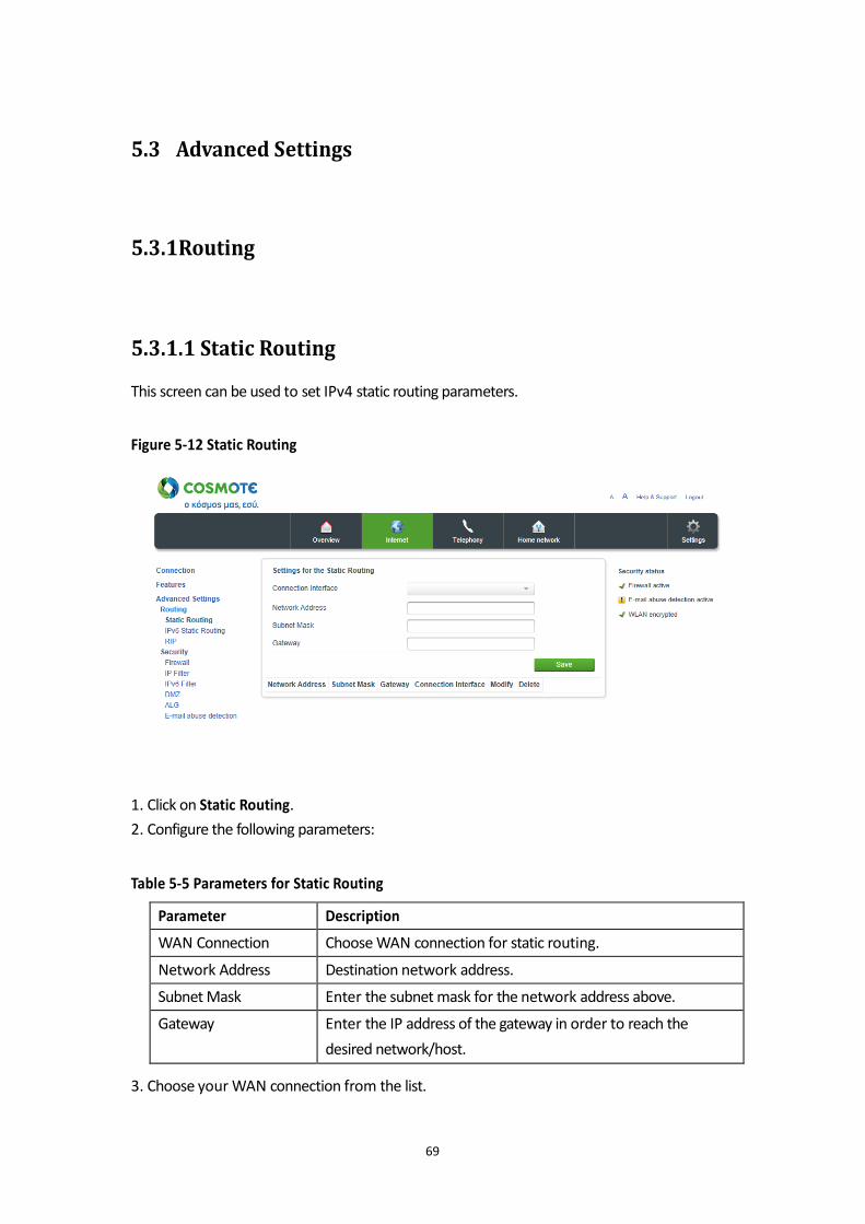
This screen can be used to set IPv4 static routing parameters. Figure 5-12 Static Routing
1. Click on Static Routing.
2. Configure the following parameters: Table 5-5 Parameters for Static Routing
3. Choose your WAN connection from the list.
69
Parameter Description
WAN Connection Choose WAN connection for static routing.
Network Address Destination network address.
Subnet Mask Enter the subnet mask for the network address above.
Gateway Enter the IP address of the gateway in order to reach the
desired network/host.

4. Enter the network address in the entry field 5. Enter the subnet mask in the entry field 6. Enter the gateway in the entry field 7. When you have modified your settings, confirm the changes by clicking the tab
.
70
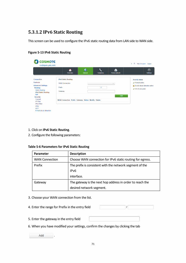
5.3.1.2 IPv6 Static Routing
This screen can be used to configure the IPv6 static routing data from LAN side to WAN side. Figure 5-13 IPv6 Static Routing
1. Click on IPv6 Static Routing.
2. Configure the following parameters: Table 5-6 Parameters for IPv6 Static Routing
3. Choose your WAN connection from the list.
4. Enter the range for Prefix in the entry field
5. Enter the gateway in the entry field 6. When you have modified your settings, confirm the changes by clicking the tab
.
71
Parameter Description
WAN Connection Choose WAN connection for IPv6 static routing for egress.
Prefix The prefix is consistent with the network segment of the
IPv6
interface.
Gateway The gateway is the next hop address in order to reach the
desired network segment.
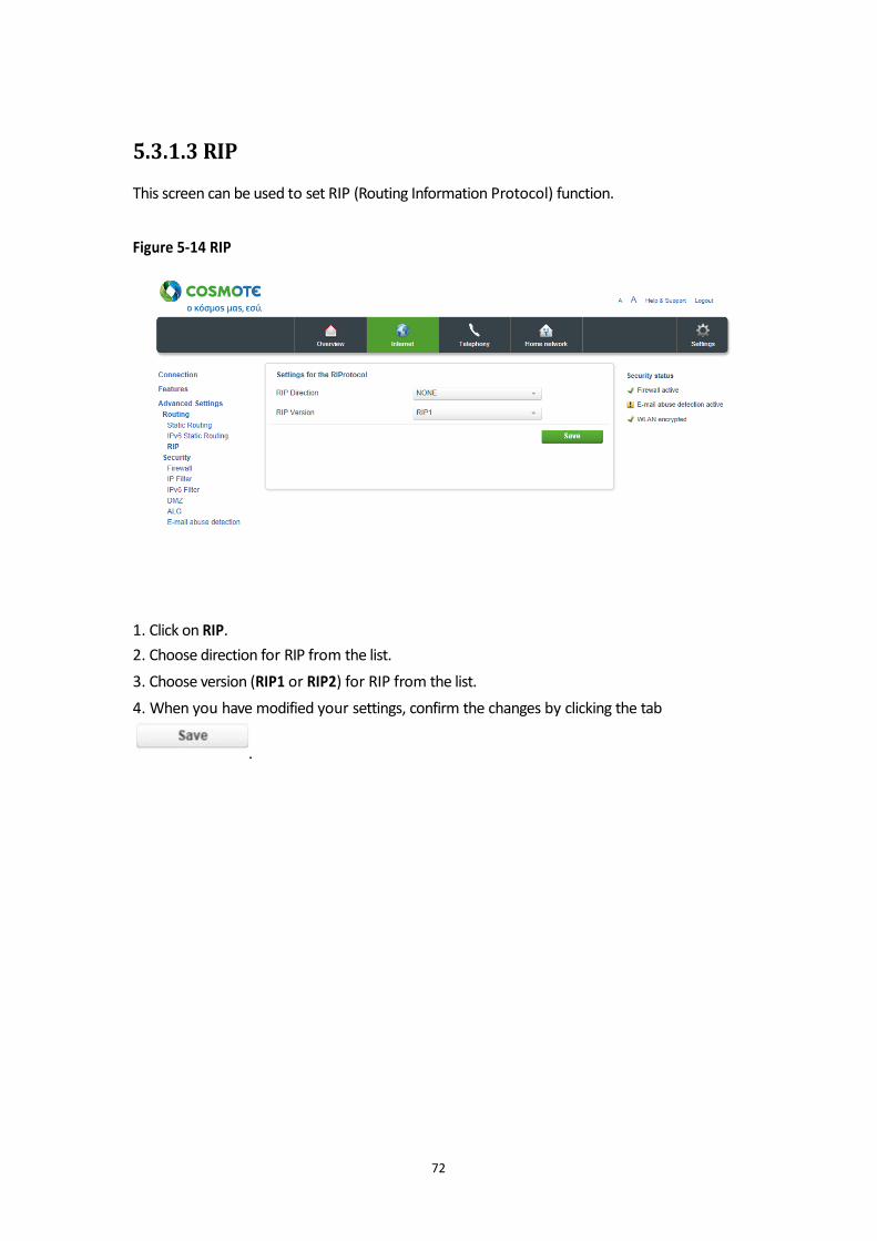
5.3.1.3 RIP
This screen can be used to set RIP (Routing Information Protocol) function. Figure 5-14 RIP
1. Click on RIP.
2. Choose direction for RIP from the list.
3. Choose version (RIP1 or RIP2) for RIP from the list.
4. When you have modified your settings, confirm the changes by clicking the tab
.
72
5.3.2 Security
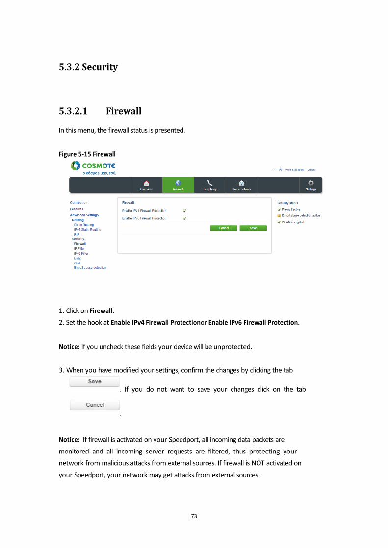
5.3.2.1 Firewall
In this menu, the firewall status is presented. Figure 5-15 Firewall
1. Click on Firewall.
2. Set the hook at Enable IPv4 Firewall Protectionor Enable IPv6 Firewall Protection. Notice: If you uncheck these fields your device will be unprotected. 3. When you have modified your settings, confirm the changes by clicking the tab
. If you do not want to save your changes click on the tab
.
Notice: If firewall is activated on your Speedport, all incoming data packets are
monitored and all incoming server requests are filtered, thus protecting your
network from malicious attacks from external sources. If firewall is NOT activated on
your Speedport, your network may get attacks from external sources.
73
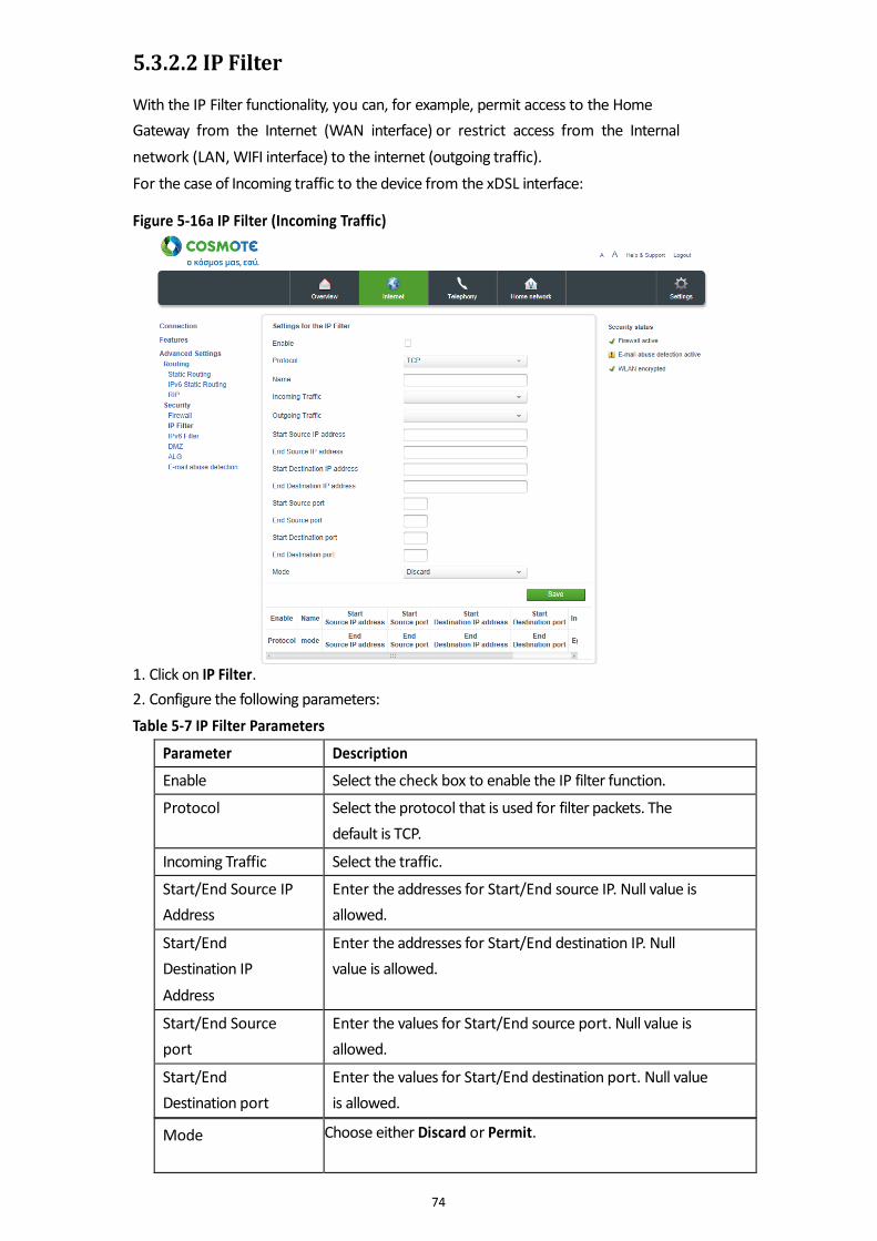
5.3.2.2 IP Filter
With the IP Filter functionality, you can, for example, permit access to the Home
Gateway from the Internet (WAN interface) or restrict access from the Internal
network (LAN, WIFI interface) to the internet (outgoing traffic).
For the case of Incoming traffic to the device from the xDSL interface: Figure 5-16a IP Filter (Incoming Traffic)
1. Click on IP Filter.
2. Configure the following parameters:
Table 5-7 IP Filter Parameters
74
Parameter Description
Enable Select the check box to enable the IP filter function.
Protocol Select the protocol that is used for filter packets. The
default is TCP.
Incoming Traffic Select the traffic.
Start/End Source IP
Address
Enter the addresses for Start/End source IP. Null value is
allowed.
Start/End
Destination IP
Address
Enter the addresses for Start/End destination IP. Null
value is allowed.
Start/End Source
port
Enter the values for Start/End source port. Null value is
allowed.
Start/End
Destination port
Enter the values for Start/End destination port. Null value
is allowed.
Mode Choose either Discard or Permit.
3. Set the hook at Enable.
4. Choose the protocol (TCP or UDP or TCP and UDP).
5. Enter the name for a new filter in the entry field
.
6. Choose what kind of traffic you need to allow ( e.g. incoming PTM Conn-x).
7. Enter start source IP address in the entry field . 8. Enter end source IP address in the entry field . 9. Enter the start/end destination port in the entry field . 10. From the available modes (Discard or Permit) choose the mode Permit.
11. When you have modified your settings, confirm the changes by clicking the tab
.
Notice: If you configure 0.0.0.0 as a Start/End Source IP address, this refers to ALL IPs
are allowed to access the Home Gateway.
75
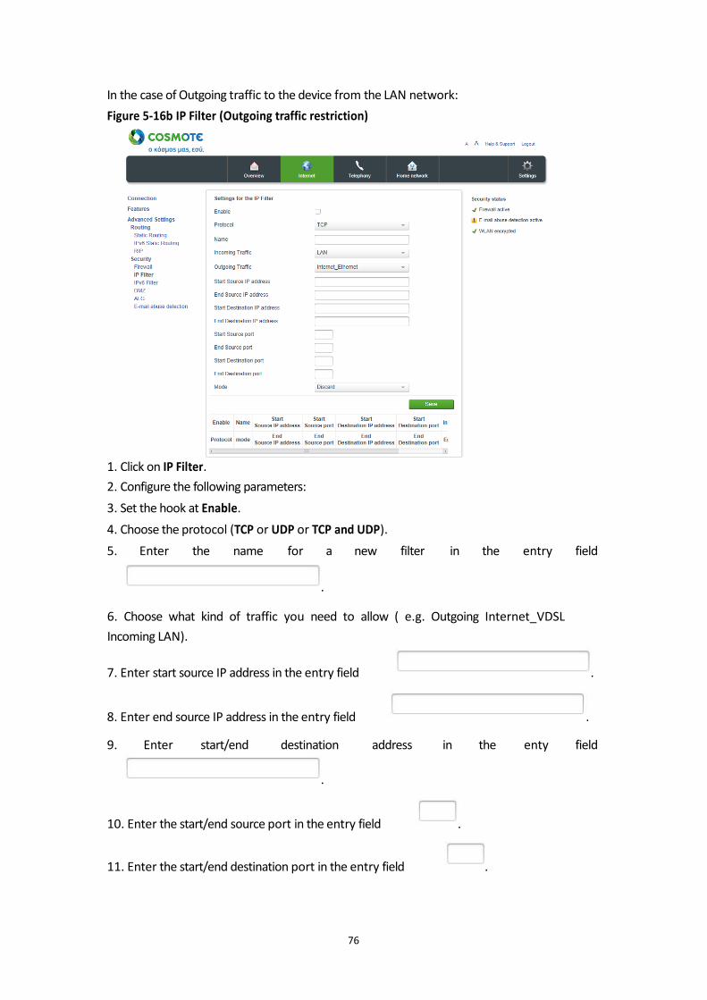
In the case of Outgoing traffic to the device from the LAN network:
Figure 5-16b IP Filter (Outgoing traffic restriction)
1. Click on IP Filter.
2. Configure the following parameters:
3. Set the hook at Enable.
4. Choose the protocol (TCP or UDP or TCP and UDP).
5. Enter the name for a new filter in the entry field
.
6. Choose what kind of traffic you need to allow ( e.g. Outgoing Internet_VDSL
Incoming LAN).
7. Enter start source IP address in the entry field . 8. Enter end source IP address in the entry field . 9. Enter start/end destination address in the enty field
.
10. Enter the start/end source port in the entry field . 11. Enter the start/end destination port in the entry field .
76
12. From the available modes (Discard or Permit) choose the mode Discard. By
default, there is no restriction for communication between the LAN clients and
Internet.
13. When you have modified your settings, confirm the changes by clicking the tab
.
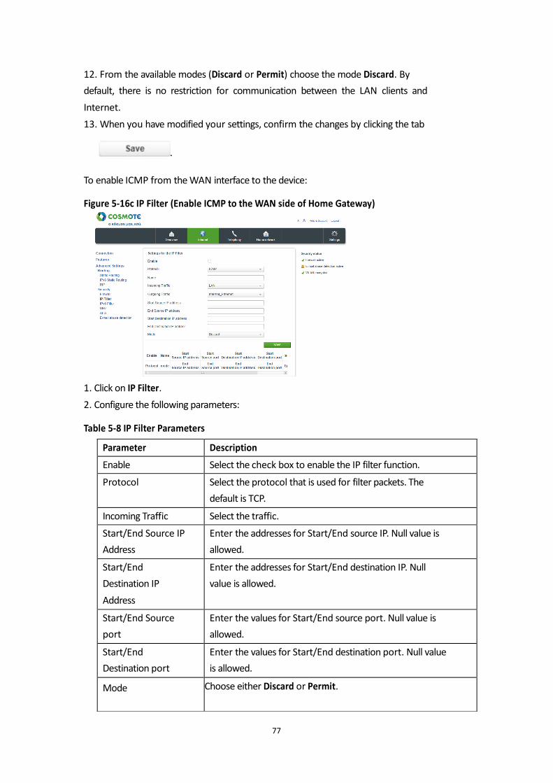
To enable ICMP from the WAN interface to the device: Figure 5-16c IP Filter (Enable ICMP to the WAN side of Home Gateway)
1. Click on IP Filter.
2. Configure the following parameters: Table 5-8 IP Filter Parameters
77
Parameter Description
Enable Select the check box to enable the IP filter function.
Protocol Select the protocol that is used for filter packets. The
default is TCP.
Incoming Traffic Select the traffic.
Start/End Source IP
Address
Enter the addresses for Start/End source IP. Null value is
allowed.
Start/End
Destination IP
Address
Enter the addresses for Start/End destination IP. Null
value is allowed.
Start/End Source
port
Enter the values for Start/End source port. Null value is
allowed.
Start/End
Destination port
Enter the values for Start/End destination port. Null value
is allowed.
Mode Choose either Discard or Permit.
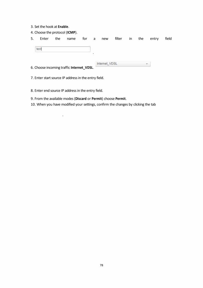
3. Set the hook at Enable.
4. Choose the protocol (ICMP).
5. Enter the name for a new filter in the entry field
.
6. Choose incoming traffic Internet_VDSL.
7. Enter start source IP address in the entry field. 8. Enter end source IP address in the entry field. 9. From the available modes (Discard or Permit) choose Permit.
10. When you have modified your settings, confirm the changes by clicking the tab
.
78
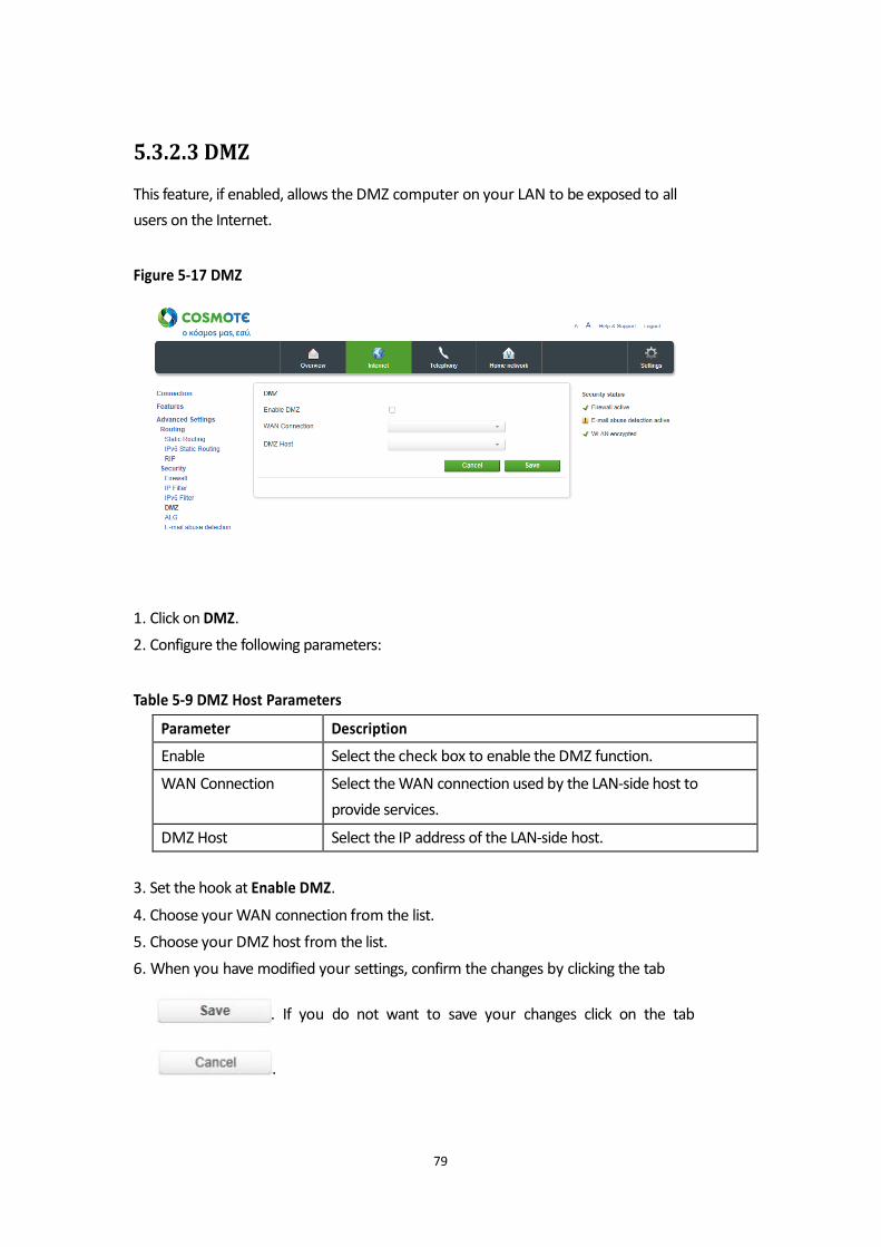
5.3.2.3 DMZ
This feature, if enabled, allows the DMZ computer on your LAN to be exposed to all
users on the Internet. Figure 5-17 DMZ
1. Click on DMZ.
2. Configure the following parameters: Table 5-9 DMZ Host Parameters
3. Set the hook at Enable DMZ.
4. Choose your WAN connection from the list.
5. Choose your DMZ host from the list.
6. When you have modified your settings, confirm the changes by clicking the tab
. If you do not want to save your changes click on the tab
.
79
Parameter Description
Enable Select the check box to enable the DMZ function.
WAN Connection Select the WAN connection used by the LAN-side host to
provide services.
DMZ Host Select the IP address of the LAN-side host.
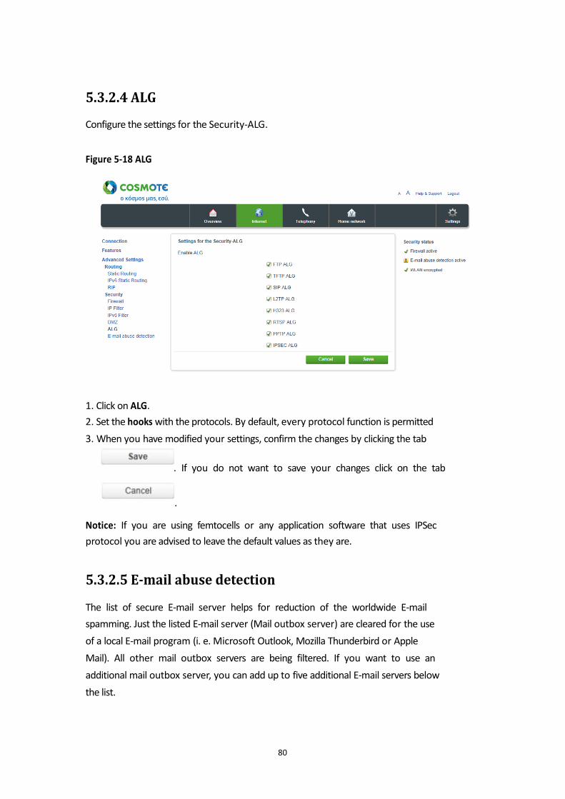
5.3.2.4 ALG
Configure the settings for the Security-ALG. Figure 5-18 ALG
1. Click on ALG.
2. Set the hooks with the protocols. By default, every protocol function is permitted
3. When you have modified your settings, confirm the changes by clicking the tab
. If you do not want to save your changes click on the tab
.
Notice: If you are using femtocells or any application software that uses IPSec
protocol you are advised to leave the default values as they are.
5.3.2.5 E-mail abuse detection
The list of secure E-mail server helps for reduction of the worldwide E-mail
spamming. Just the listed E-mail server (Mail outbox server) are cleared for the use
of a local E-mail program (i. e. Microsoft Outlook, Mozilla Thunderbird or Apple
Mail). All other mail outbox servers are being filtered. If you want to use an
additional mail outbox server, you can add up to five additional E-mail servers below
the list.
80
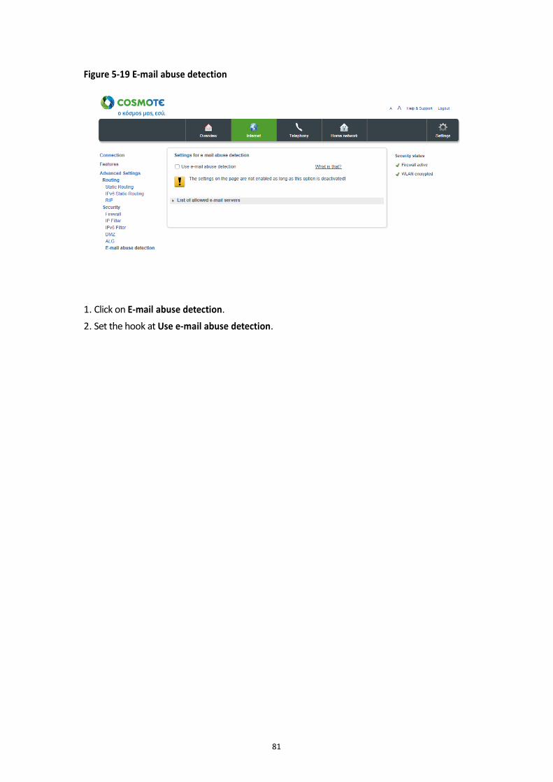
Figure 5-19 E-mail abuse detection
1. Click on E-mail abuse detection.
2. Set the hook at Use e-mail abuse detection.
81
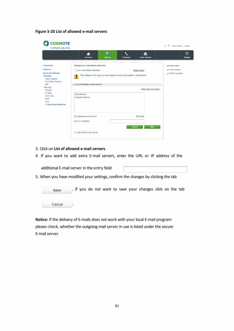
Figure 5-20 List of allowed e-mail servers
3. Click on List of allowed e-mail servers.
4. If you want to add extra E-mail servers, enter the URL or IP address of the
additional E-mail server in the entry field
5. When you have modified your settings, confirm the changes by clicking the tab
. If you do not want to save your changes click on the tab
.
Notice: If the delivery of E-mails does not work with your local E-mail program
please check, whether the outgoing mail server in use is listed under the secure
E-mail server.
82
Chapter 6 Home Network Menu
The Wireless home network or WLAN (Wireless Local Area Network) consists over
components, which are connected via radio wave. It enables the Wireless connection
of your notebook, your printer or other WLAN capable devices with your Speedport.
You have two frequency bands available.
In the menu Basic WLAN settings you can modify the WLAN settings according to
your requirements. You can assign WLAN names, set different encryption methods,
configure timer and modify the transmission settings.
6.1 Basic WLAN settings
Figure 6-1 Basic settings for WLAN
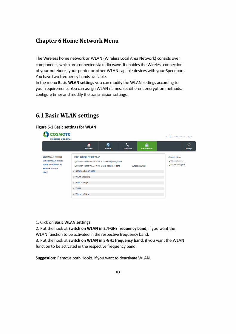
1. Click on Basic WLAN settings.
2. Put the hook at Switch on WLAN in 2.4-GHz frequency band, if you want the
WLAN function to be activated in the respective frequency band.
3. Put the hook at Switch on WLAN in 5-GHz frequency band, if you want the WLAN
function to be activated in the respective frequency band.
Suggestion: Remove both Hooks, if you want to deactivate WLAN.
83
Suggestion: By pressing the WLAN button on the front side of your Speedport
frequency bands will be activated and deactivated at the same time.
6.1.1 SSID Settings
The WLAN name, also called SSID (Service Set IDentifier) helps to distinguish
between Wireless home networks in the same location. The WLAN name must be
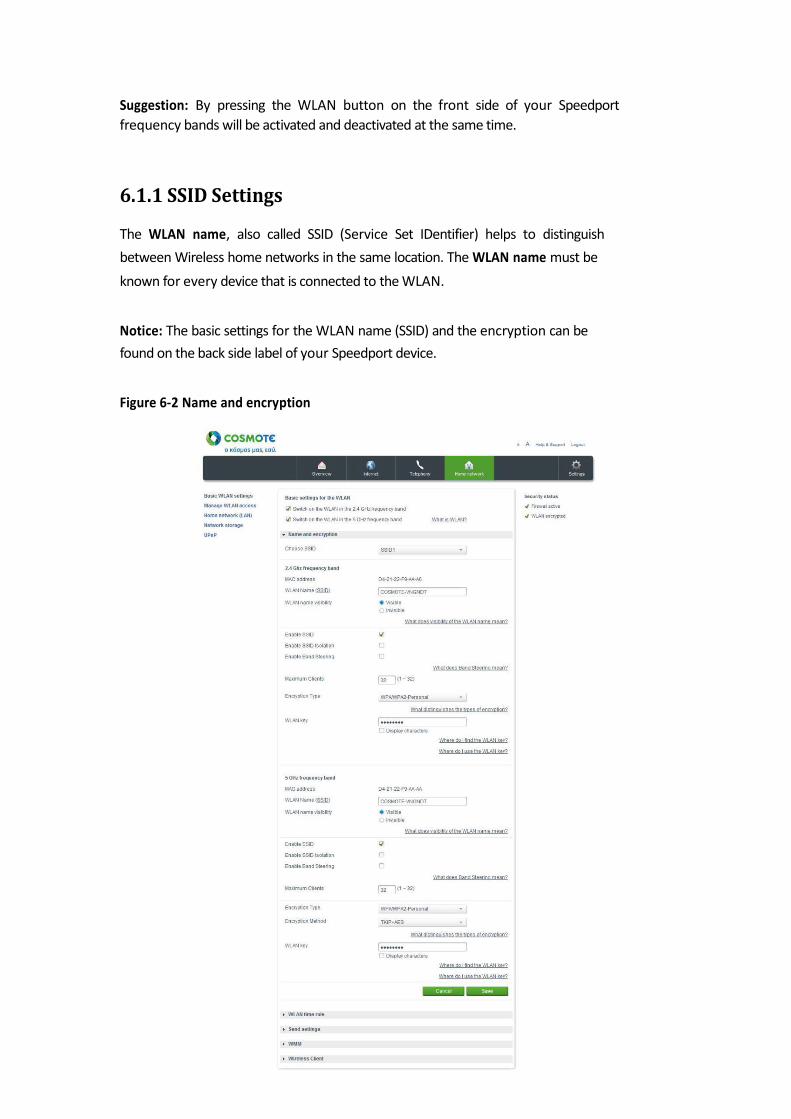
known for every device that is connected to the WLAN. Notice: The basic settings for the WLAN name (SSID) and the encryption can be
found on the back side label of your Speedport device. Figure 6-2 Name and encryption

1. Click on Basic WLAN settings.
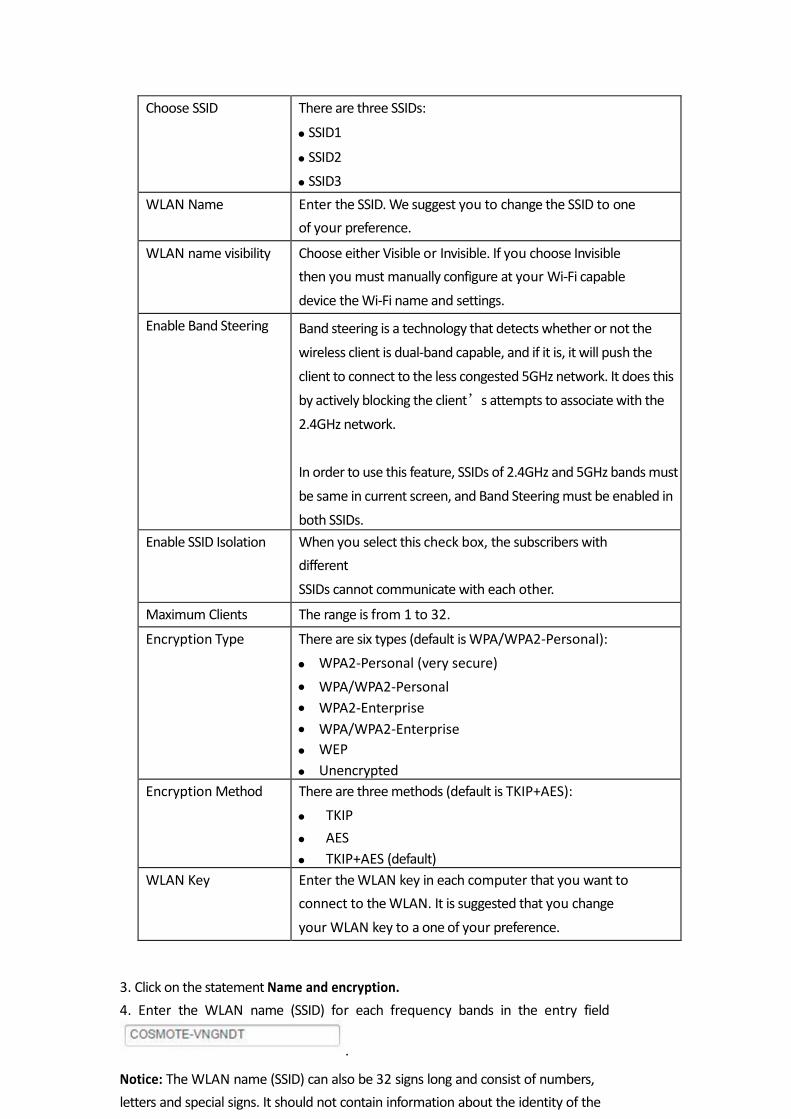
2. Configure the following parameters: Table 6-1 Parameters for SSID Settings
Parameter Description
84
3. Click on the statement Name and encryption.
4. Enter the WLAN name (SSID) for each frequency bands in the entry field
.
Notice: The WLAN name (SSID) can also be 32 signs long and consist of numbers,
letters and special signs. It should not contain information about the identity of the
Choose SSID There are three SSIDs:
SSID1
SSID2
SSID3
WLAN Name Enter the SSID. We suggest you to change the SSID to one
of your preference.
WLAN name visibility Choose either Visible or Invisible. If you choose Invisible
then you must manually configure at your Wi-Fi capable
device the Wi-Fi name and settings.
Enable Band Steering Band steering is a technology that detects whether or not the
wireless client is dual-band capable, and if it is, it will push the
client to connect to the less congested 5GHz network. It does this
by actively blocking the client’s attempts to associate with the
2.4GHz network.
In order to use this feature, SSIDs of 2.4GHz and 5GHz bands must
be same in current screen, and Band Steering must be enabled in
both SSIDs.
Enable SSID Isolation When you select this check box, the subscribers with
different
SSIDs cannot communicate with each other.
Maximum Clients The range is from 1 to 32.
Encryption Type There are six types (default is WPA/WPA2-Personal):
WPA2-Personal (very secure)
WPA/WPA2-Personal
WPA2-Enterprise
WPA/WPA2-Enterprise
WEP
Unencrypted
Encryption Method There are three methods (default is TKIP+AES):
TKIP
AES
TKIP+AES (default)
WLAN Key Enter the WLAN key in each computer that you want to
connect to the WLAN. It is suggested that you change
your WLAN key to a one of your preference.

Wireless home network, meaning no family or company names as well as birth days.
Please observe the upper and lower case. The connection to network capable
devices, which do not use valid WLAN names (SSID) will be interrupted until valid
WLAN names (SSID) are also established there.
5. Choose the WLAN name, which is to be displayed (visible or invisible).
85
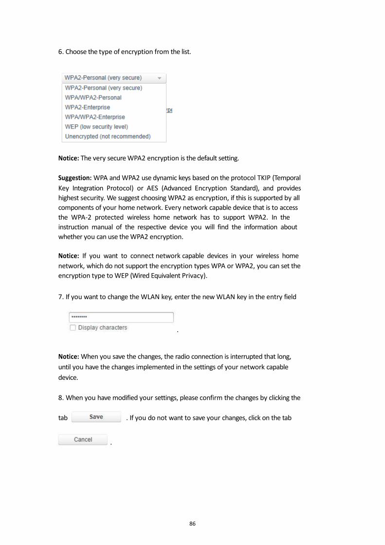
6. Choose the type of encryption from the list.
Notice: The very secure WPA2 encryption is the default setting.
Suggestion: WPA and WPA2 use dynamic keys based on the protocol TKIP (Temporal
Key Integration Protocol) or AES (Advanced Encryption Standard), and provides
highest security. We suggest choosing WPA2 as encryption, if this is supported by all
components of your home network. Every network capable device that is to access
the WPA-2 protected wireless home network has to support WPA2. In the
instruction manual of the respective device you will find the information about
whether you can use the WPA2 encryption.
Notice: If you want to connect network capable devices in your wireless home
network, which do not support the encryption types WPA or WPA2, you can set the
encryption type to WEP (Wired Equivalent Privacy).
7. If you want to change the WLAN key, enter the new WLAN key in the entry field
.
Notice: When you save the changes, the radio connection is interrupted that long,
until you have the changes implemented in the settings of your network capable
device.
8. When you have modified your settings, please confirm the changes by clicking the
tab . If you do not want to save your changes, click on the tab
.
86
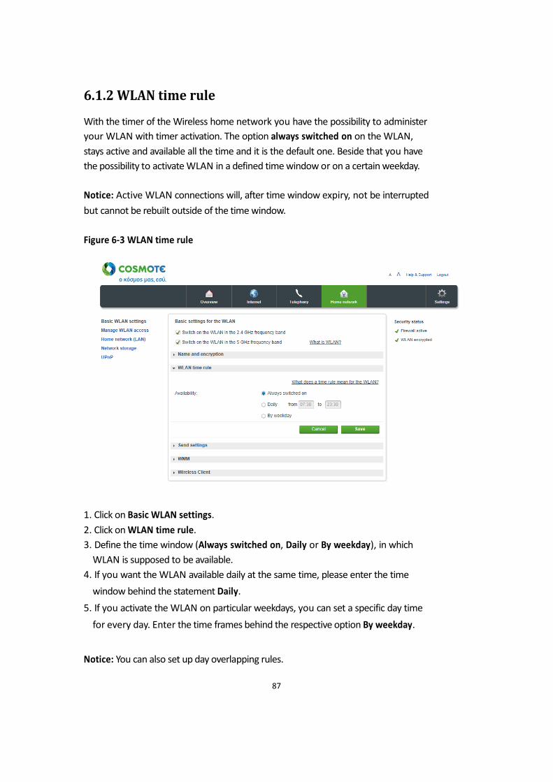
6.1.2 WLAN time rule
With the timer of the Wireless home network you have the possibility to administer
your WLAN with timer activation. The option always switched on on the WLAN,
stays active and available all the time and it is the default one. Beside that you have
the possibility to activate WLAN in a defined time window or on a certain weekday.
Notice: Active WLAN connections will, after time window expiry, not be interrupted
but cannot be rebuilt outside of the time window.
Figure 6-3 WLAN time rule
1. Click on Basic WLAN settings.
2. Click on WLAN time rule.
3. Define the time window (Always switched on, Daily or By weekday), in which
WLAN is supposed to be available.
4. If you want the WLAN available daily at the same time, please enter the time
window behind the statement Daily.
5. If you activate the WLAN on particular weekdays, you can set a specific day time
for every day. Enter the time frames behind the respective option By weekday.
Notice: You can also set up day overlapping rules.
87
6. When you have modified your settings, please confirm the changes by clicking the
tab . If you do not want to save your changes, click on the tab
.
6.1.3 Send settings
In the menu Send settings you can define the transmission performance, the
transmission mode, the speed and the channel of your Wireless network. Transmission performance.
Here you can set the transmission performance, with which your Speedport
communicates with other network capable devices in the Wireless home network. If
your network capable devices are placed nearby your Speedport you can reduce the
transmission performance. You can change the range of your Wireless network as
follows:
· Full transmission performance = maximum range (100 % transmission
performance).
· Middle transmission performance = middle range (31 %-60 % transmission
performance).
· Low transmission performance = low range (15 %-30 % transmission performance).
88
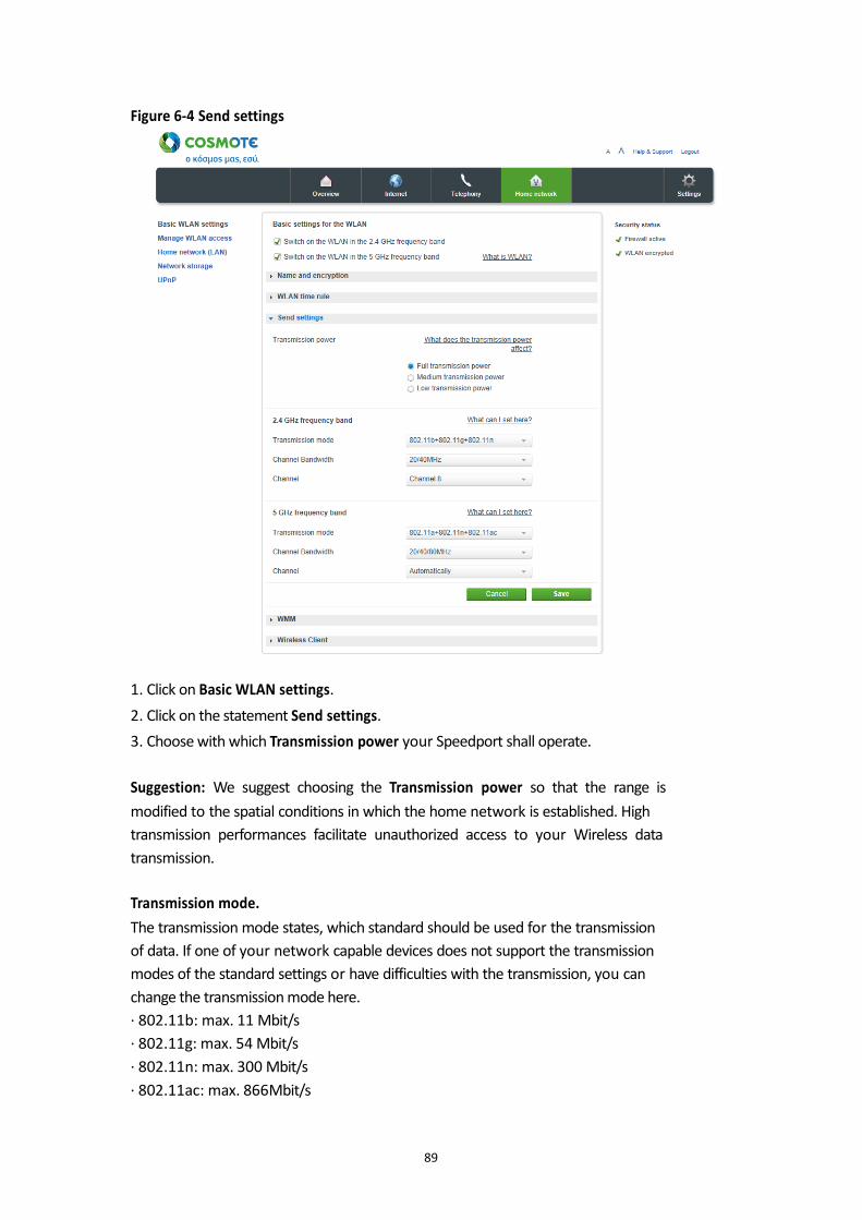
Figure 6-4 Send settings
1. Click on Basic WLAN settings.
2. Click on the statement Send settings.
3. Choose with which Transmission power your Speedport shall operate.
Suggestion: We suggest choosing the Transmission power so that the range is
modified to the spatial conditions in which the home network is established. High
transmission performances facilitate unauthorized access to your Wireless data
transmission.
Transmission mode.
The transmission mode states, which standard should be used for the transmission
of data. If one of your network capable devices does not support the transmission
modes of the standard settings or have difficulties with the transmission, you can
change the transmission mode here.
· 802.11b: max. 11 Mbit/s
· 802.11g: max. 54 Mbit/s
· 802.11n: max. 300 Mbit/s
· 802.11ac: max. 866Mbit/s
89
Normally Speedport chooses the best radio channel for the transmission. Yet you can
choose the radio channel by yourself. But please notice, that, between your radio
channel in use and the used radio channel in your environment, at least four
channels have to remain unused. With this way you can use your wireless home
network without interference. Please also notice that the radio channels 12 and 13
are not supported by all network capable devices.
Notice: You can modify the settings separately for both frequency bands.
1. Click on WLAN basic settings.
2. Configure the following parameters: Table 6-2 Send Settings Parameters
3. Click on Send settings.
4. Choose depending on the frequency band the transmission mode form the
respective list.
5. Select Channel Bandwidth to 20/40MHz or 20/40/80MHz, if you want to
increase the maximum transmission speed to 300 Mbit/s or 866 Mbit/s (5G Band Only).
6. Choose the radio channel from the list, in which the transmission for the home
network is to be carried out. We suggest to choose Automatically. Choose
specifically channel 1 or 6 or 11, if you have already scan your environment to find a
90
Parameter Description
Transmission power There are three options:
Full transmission power (default)
Medium transmission power
Low transmission power
Transmission mode There are three modes for 2.4GHz:
802.11b+802.11g
802.11g+802.11n
802.11b+802.11g+802.11n (default)
There are three modes for 5GHz:
802.11ac
802.11+802.11ac
802.11a+802.11n+802.11ac (default)
Speed It is chosen automatically by the device.
Channel Select the best wireless channel for transmission.
Rate Limit Choose the option for rate limit.
least congested frequency channel. Automatic mode may choose to use wireless
channels that are being overlapped. Suggestion: The available radio channels differ by their frequency width. Notice: The available radio channels are defined by country specific rules and can be
limited. That is why that some network components might not support all channels. 7. When you have modified your settings, please confirm the changes by clicking the
tab If you do not want to save your changes, click on the tab
.
91

6.1.4 WMM
Perform this procedure to configure WLAN WMM. Figure 6-5 WMM
1. Click on Basic WLAN settings.
2. Click on the statement WMM.
3. Set the parameters as required.
Table 6-3 WMM Parameters
92
Parameter Description
Choose AC There are four options:
BE (default)
BK
VI
VO
AIFSN Arbitration inter frame spacing number
Range: 2–15
ECWMin Exponent form of minimum competition window
Range: 0–15

93
ECWMax Exponent form of maximum competition window
Range: 0–15
TXOP Transmission opportunity limit
Range: 0–255
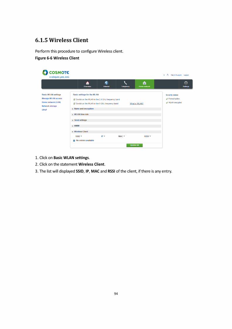
6.1.5 Wireless Client
Perform this procedure to configure Wireless client.
Figure 6-6 Wireless Client
1. Click on Basic WLAN settings.
2. Click on the statement Wireless Client.
3. The list will displayed SSID, IP, MAC and RSSI of the client, if there is any entry.
94
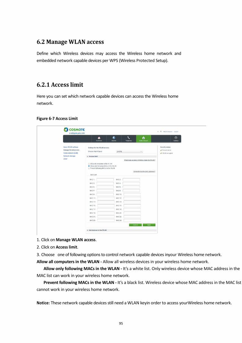
6.2 Manage WLAN access
Define which Wireless devices may access the Wireless home network and
embedded network capable devices per WPS (Wireless Protected Setup).
6.2.1 Access limit
Here you can set which network capable devices can access the Wireless home
network. Figure 6-7 Access Limit
1. Click on Manage WLAN access.
2. Click on Access limit.
3. Choose one of following options to control network capable devices inyour Wireless home network.
Allow all computers in the WLAN - Allow all wireless devices in your wireless home network.
Allow only following MACs in the WLAN - It’s a white list. Only wireless device whose MAC address in the
MAC list can work in your wireless home network.
Prevent following MACs in the WLAN - It’s a black list. Wireless device whose MAC address in the MAC list
cannot work in your wireless home network.
Notice: These network capable devices still need a WLAN keyin order to access yourWireless home network.
95
4. When you have modified your settings, please confirm the changes by clicking the
tab . If you do not want to save your changes, click on the tab
.
Add network capable devices via WPS to the wireless home network.
You can connect network capable devices via WPS (Wireless Protected Setup) with
your wireless home network. WPS helps the easy embedment of network capable
devices in your protected wireless home network. One requirement is, the network
capable components to support WPS.
You can connect your network capable devices by pressing a button (PBC
method) or PIN entry with your wireless home network.
Suggestion: If you use the encryption WEP, you cannot add network components via
WPS to your Wireless home network. We suggest the use of the very secure WPA2
encryption.
96
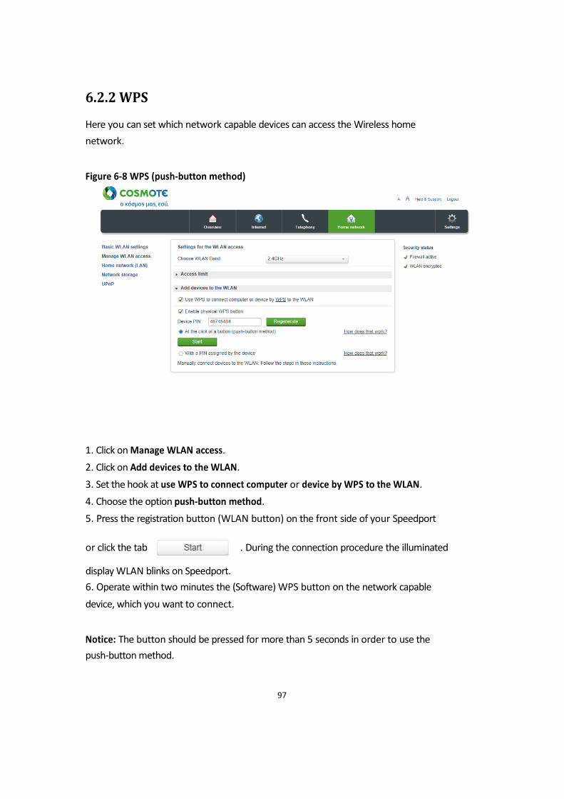
6.2.2 WPS
Here you can set which network capable devices can access the Wireless home
network. Figure 6-8 WPS (push-button method)
1. Click on Manage WLAN access.
2. Click on Add devices to the WLAN.
3. Set the hook at use WPS to connect computer or device by WPS to the WLAN.
4. Choose the option push-button method.
5. Press the registration button (WLAN button) on the front side of your Speedport
or click the tab . During the connection procedure the illuminated display WLAN blinks on Speedport.
6. Operate within two minutes the (Software) WPS button on the network capable
device, which you want to connect. Notice: The button should be pressed for more than 5 seconds in order to use the
push-button method.
97
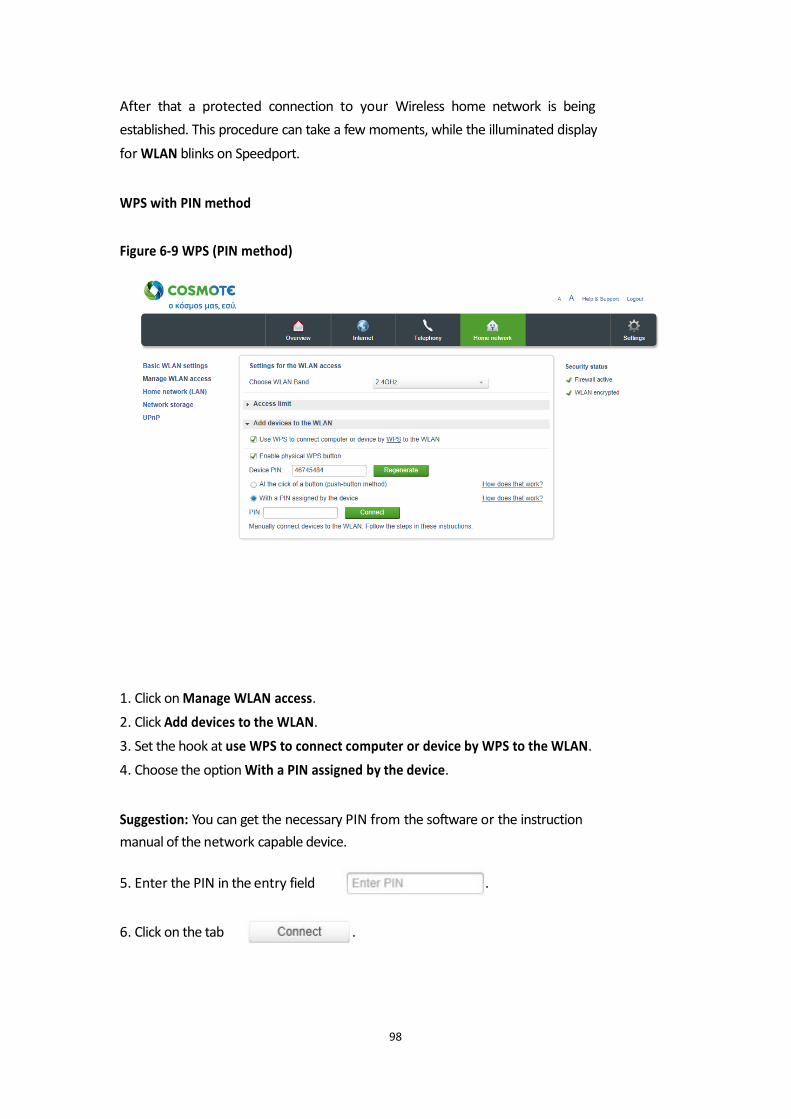
After that a protected connection to your Wireless home network is being
established. This procedure can take a few moments, while the illuminated display
for WLAN blinks on Speedport. WPS with PIN method Figure 6-9 WPS (PIN method)
1. Click on Manage WLAN access.
2. Click Add devices to the WLAN.
3. Set the hook at use WPS to connect computer or device by WPS to the WLAN.
4. Choose the option With a PIN assigned by the device. Suggestion: You can get the necessary PIN from the software or the instruction
manual of the network capable device.
5. Enter the PIN in the entry field . 6. Click on the tab .
98
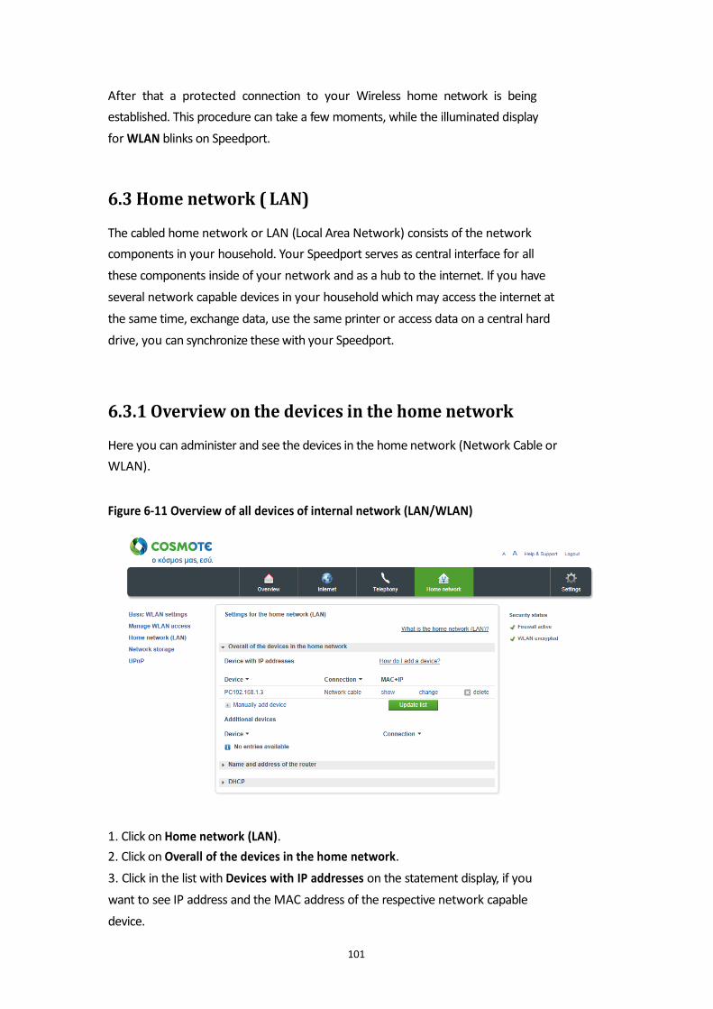
After that a protected connection to your Wireless home network is being
established. This procedure can take a few moments, while the illuminated display
for WLAN blinks on Speedport.
6.3 Home network ( LAN)
The cabled home network or LAN (Local Area Network) consists of the network
components in your household. Your Speedport serves as central interface for all
these components inside of your network and as a hub to the internet. If you have
several network capable devices in your household which may access the internet at
the same time, exchange data, use the same printer or access data on a central hard
drive, you can synchronize these with your Speedport.
6.3.1 Overview on the devices in the home network
Here you can administer and see the devices in the home network (Network Cable or
WLAN). Figure 6-11 Overview of all devices of internal network (LAN/WLAN)
1. Click on Home network (LAN).
2. Click on Overall of the devices in the home network.
3. Click in the list with Devices with IP addresses on the statement display, if you
want to see IP address and the MAC address of the respective network capable
device.
101
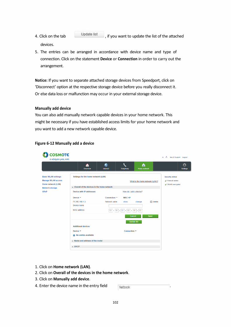
4. Click on the tab , if you want to update the list of the attached
devices.
5. The entries can be arranged in accordance with device name and type of
connection. Click on the statement Device or Connection in order to carry out the
arrangement.
Notice: If you want to separate attached storage devices from Speedport, click on
‘Disconnect’ option at the respective storage device before you really disconnect it.
Or else data loss or malfunction may occur in your external storage device. Manually add device
You can also add manually network capable devices in your home network. This
might be necessary if you have established access limits for your home network and
you want to add a new network capable device. Figure 6-12 Manually add a device
1. Click on Home network (LAN).
2. Click on Overall of the devices in the home network.
3. Click on Manually add device.
4. Enter the device name in the entry field .
102
5. Enter the MAC addresses of the respective network capable device in entry fields
. The MAC addresses can be found in the system or network
information of the device.
6. Once you have modifieded the settings, confirm the changes by clicking the tab
. If you do not want to save changes, click on the tab
.
Additional devices in the home network
1. Click on Home network (LAN).
2. Click on Overall of the devices in the home network.
3. Under the statement Additional devices you can see connected devices to your
Speedport.
4. The entries can be arranged in accordance with type of connection or device
name. Click on the entry Device or Connection to carry out the arrangement. Notice: If you want to separate the connected storage media from Speedport, click
on disconnect before physically removing it. Otherwise, loss of data or
malfunctioning may occur to your USB device.
103
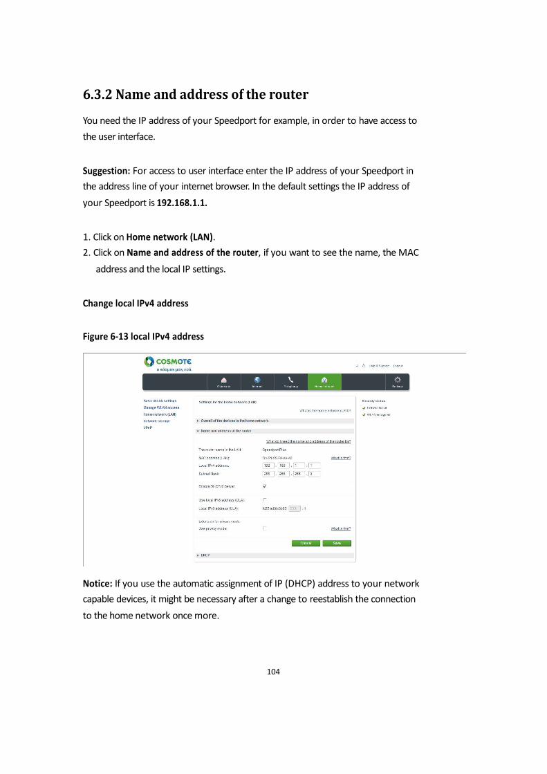
6.3.2 Name and address of the router
You need the IP address of your Speedport for example, in order to have access to
the user interface. Suggestion: For access to user interface enter the IP address of your Speedport in
the address line of your internet browser. In the default settings the IP address of
your Speedport is 192.168.1.1. 1. Click on Home network (LAN).
2. Click on Name and address of the router, if you want to see the name, the MAC
address and the local IP settings.
Change local IPv4 address Figure 6-13 local IPv4 address
Notice: If you use the automatic assignment of IP (DHCP) address to your network
capable devices, it might be necessary after a change to reestablish the connection
to the home network once more.
104
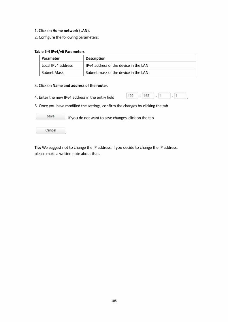
1. Click on Home network (LAN).
2. Configure the following parameters: Table 6-4 IPv4/v6 Parameters
3. Click on Name and address of the router.
4. Enter the new IPv4 address in the entry field .
5. Once you have modified the settings, confirm the changes by clicking the tab
. If you do not want to save changes, click on the tab
.
Tip: We suggest not to change the IP address. If you decide to change the IP address,
please make a written note about that.
105
Parameter Description
Local IPv4 address IPv4 address of the device in the LAN.
Subnet Mask Subnet mask of the device in the LAN.
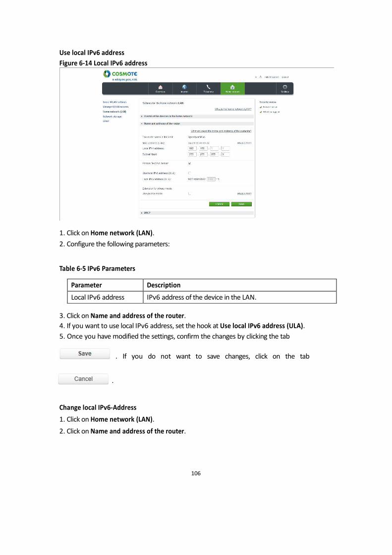
Use local IPv6 address
Figure 6-14 Local IPv6 address
1. Click on Home network (LAN).
2. Configure the following parameters: Table 6-5 IPv6 Parameters 3. Click on Name and address of the router.
4. If you want to use local IPv6 address, set the hook at Use local IPv6 address (ULA).
5. Once you have modified the settings, confirm the changes by clicking the tab
. If you do not want to save changes, click on the tab
.
Change local IPv6-Address
1. Click on Home network (LAN).
2. Click on Name and address of the router.
106
Parameter Description
Local IPv6 address IPv6 address of the device in the LAN.

3. Enter the new IPv6 address in the entry field, for example,
.
4. Once you have modified the settings, confirm the changes by clicking the tab
. If you do not want to save changes, click on the tab
.
107
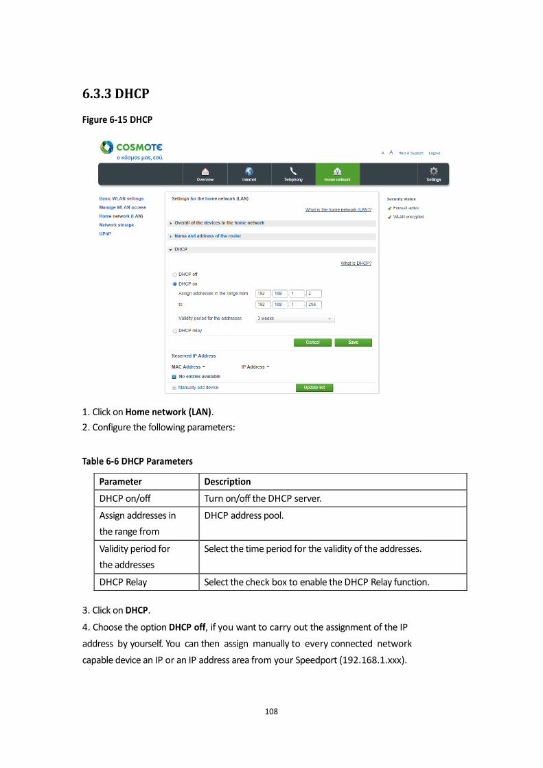
6.3.3 DHCP
Figure 6-15 DHCP
1. Click on Home network (LAN).
2. Configure the following parameters: Table 6-6 DHCP Parameters
3. Click on DHCP.
4. Choose the option DHCP off, if you want to carry out the assignment of the IP
address by yourself. You can then assign manually to every connected network
capable device an IP or an IP address area from your Speedport (192.168.1.xxx).
108
Parameter Description
DHCP on/off Turn on/off the DHCP server.
Assign addresses in
the range from
DHCP address pool.
Validity period for
the addresses
Select the time period for the validity of the addresses.
DHCP Relay Select the check box to enable the DHCP Relay function.
Choose the option DHCP on, if your Speedport should carry out the address
assignment automatically by itself. In order to make the assignment of IP addresses
work, the option Receive IP addresses automatically or DHCP should be activated
for the connected network capable devices in the network settings. Notice: The configurable address area in the standard settings lies between
192.168.1.2 and 192.168.1.254. The address area can be limited further by
configuring the start and end addresses. The time of validity of IP addresses can be
preset. After this validity has expired the connected device requests automatically to
the new IP address from the available address area. 5. Once you have modified the settings, confirm the changes by clicking the tab
. If you do not want to save changes, click on the tab
.
Notice: If DHCP is activated on your Speedport, it configures the network settings of
the connected network capable devices if the option ‘Receive IP address
automatically’ is activated on the Network Settings of your devices.
109
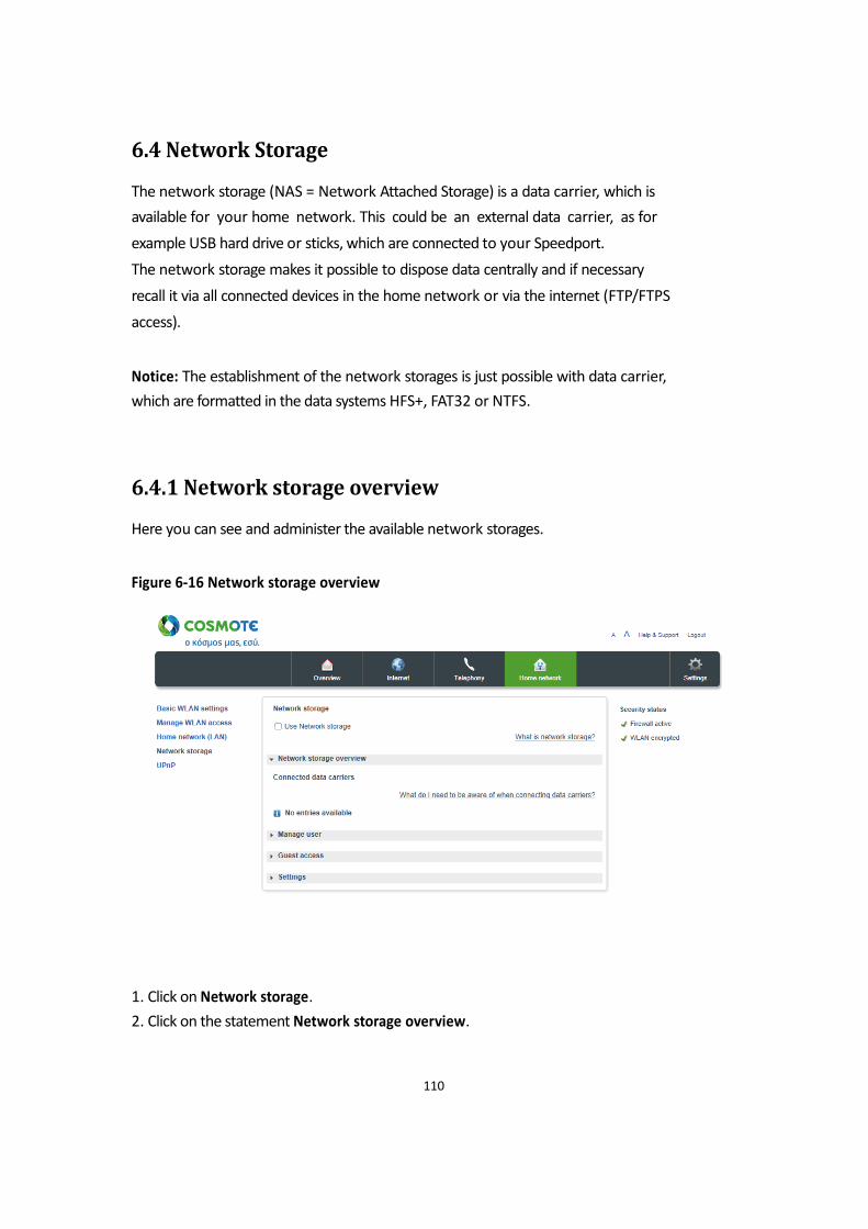
6.4 Network Storage
The network storage (NAS = Network Attached Storage) is a data carrier, which is
available for your home network. This could be an external data carrier, as for
example USB hard drive or sticks, which are connected to your Speedport.
The network storage makes it possible to dispose data centrally and if necessary
recall it via all connected devices in the home network or via the internet (FTP/FTPS
access). Notice: The establishment of the network storages is just possible with data carrier,
which are formatted in the data systems HFS+, FAT32 or NTFS.
6.4.1 Network storage overview
Here you can see and administer the available network storages. Figure 6-16 Network storage overview
1. Click on Network storage.
2. Click on the statement Network storage overview.
110
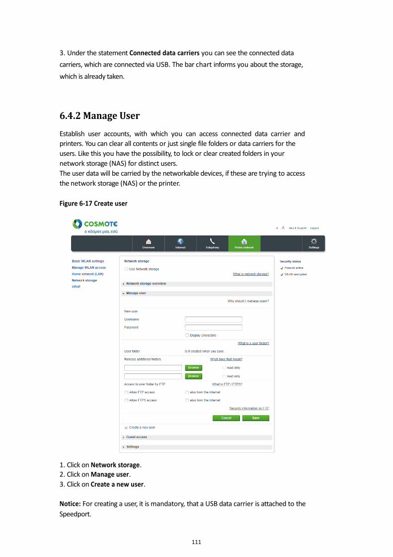
3. Under the statement Connected data carriers you can see the connected data
carriers, which are connected via USB. The bar chart informs you about the storage,
which is already taken.
6.4.2 Manage User
Establish user accounts, with which you can access connected data carrier and
printers. You can clear all contents or just single file folders or data carriers for the
users. Like this you have the possibility, to lock or clear created folders in your
network storage (NAS) for distinct users.
The user data will be carried by the networkable devices, if these are trying to access
the network storage (NAS) or the printer.
Figure 6-17 Create user
1. Click on Network storage. 2. Click on Manage user.
3. Click on Create a new user.
Notice: For creating a user, it is mandatory, that a USB data carrier is attached to the
Speedport.
111
4. Enter the name of the user in the entry field .
5. Enter the personal password, that will be used for the user in the entry field
.
Notice: Choose secure passwords. We suggest a combination of numbers and letters
(Upper and lower cases) with at least eight signs, which do not make any
recognizable sense (i.e. H7zt9kkoM5).
6. The user folder will be created automatically on a connected USB storage during
saving of the user account. The user folder is exclusively available for the user with
reading and writing rights. Other users cannot access it. Just a user with
administrator rights can access the folder.
Notice: For registration at the network storage with administrator rights use the user
name admin and the device password of your Speedport.
7. Click on , if you want additional folders cleared for the user.
Notice: For every user at most two folders can be cleared.
8. Set the hook at read only, if user just should have reading rights in the additional
folder.
9. Click on Release additional folders, if you want to make additional folders
accessible for the user.
10. Once you have adapted the settings, confirm the changes by clicking the tab
. If you do not want to save changes, click on the tab
.
112
6.4.3 Access via FTP/FTPS
FTP (File Transfer Protocol) is a protocol for data transmission. Allow the access, if
you want to access your network storage (NAS) via internet from far. FTPS (FTP via
SSL) is an encrypted variant and therefore more secure than FTP.
Suggestion: You can also access from your home network via FTP/FTPS to the
network storage connected to your Speedport.
For the access via internet your Speedport has to get a name in the internet. For that
you can choose from different services for dynamic DNS, i. e. dyndns.org. If you have
booked a service enter the access data in the menu Internet - DDNS.
Suggestion: Further information for the settings of dynamic DNS can be found in the
section DDNS.
With an FTP program you can with every networkable device on your network
storage and exchange data.
1. Click on Network storage.
2. Create a user first (see chapter Create user)
3. Set the hook at Allow FTP access or at Allow FTPS access, if you want to allow
access via FTP or FTPS.
4. Set the hook at also from the internet, if you want to allow access from the
internet as well. If you do not set this hook, you will just reach your network
storage via FTP from within your home network.
Notice: Via FTP the authentication data (User name, personal password) and the
data transmission will be sent unencrypted. We suggest the use of FTPS. 5. Once you have adapted the settings, confirm the changes by clicking the tab
. If you do not want to save changes, click on the tab
.
113
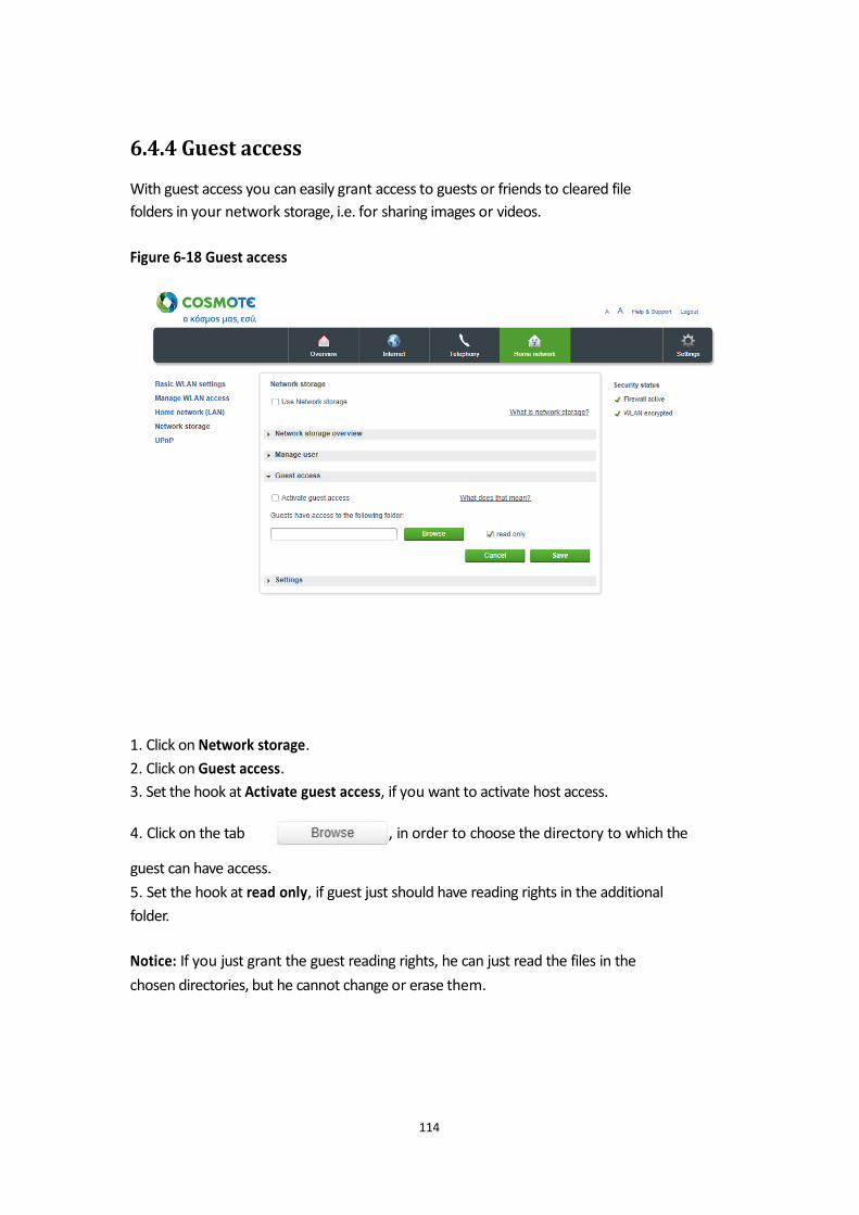
6.4.4 Guest access
With guest access you can easily grant access to guests or friends to cleared file
folders in your network storage, i.e. for sharing images or videos.
Figure 6-18 Guest access
1. Click on Network storage.
2. Click on Guest access.
3. Set the hook at Activate guest access, if you want to activate host access.
4. Click on the tab , in order to choose the directory to which the guest can have access.
5. Set the hook at read only, if guest just should have reading rights in the additional
folder.
Notice: If you just grant the guest reading rights, he can just read the files in the
chosen directories, but he cannot change or erase them.
114
6. Once you have adapted the settings, confirm the changes by clicking the tab
. If you do not want to save changes, click on the tab
.
Notice: For registration as host enter the user name GUEST and create any personal
password consisting of at least one sign.
6.4.5 Settings
Used work group
For recognition of the different networking devices within a home network, they are
grouped together in workgroups. Windows list the recognized devices in the file
explorer under network environment (or network). Via these entries the network
storages (NAS) connected to your Speedport can also have access. The default
setting in your Speedport is the work group WORKGROUP. Depending on the
Windows Version different standard work groups will be in use. Table 6-7 Workgroup
If the same work group name is set, the access to the network storage is facilitated.
You can modify the work group name either in the Speedport or in the respective
networking device. If the work group name does not match, you can also, via direct
path entry, to access the network storage.
1. Click on Network storage.
2. Click on Settings.
3. Enter the respective work group name in the entry field.
115
Operation System Name of work group
Windows XP Home Edition WORKGROUP
Windows XP Professional WORKGROUP
Windows Vista WORKGROUP
Windows 7 WORKGROUP
Windows 8 WORKGROUP

4. Once you have adapted the settings, confirm the changes by clicking the tab
. If you do not want to save changes, click on the tab
.
Media playback
By media playback you label the folders on the attached data carriers as media
folders. Media folders contain music, photos or videos.
The indication of the media folder contains the file formats MP3, M4A (w/o DRM),
WMA (w/o DRM), WMV (w/o DRM), JPG, PNG, AVI, DivX, Xvid and MPEG2. Notice: Depending on the size/speed of the used storage, it may take some time for
the used storage to be identified. The content of media folders can be recognized by the appropriate playback devices
in your home network automatically, as long as these devices provide the standards
DLNA or UPnP AV and support the respective file formats. Notice: If a file format in an media folder is not supported by the playback device,
the respective file cannot be played back. The media server is active, as soon as one directory has been cleared. Notice: If you clear directories for media playback, all participants in the home
network can display the media files. An access control does not exist then for these
files.
116
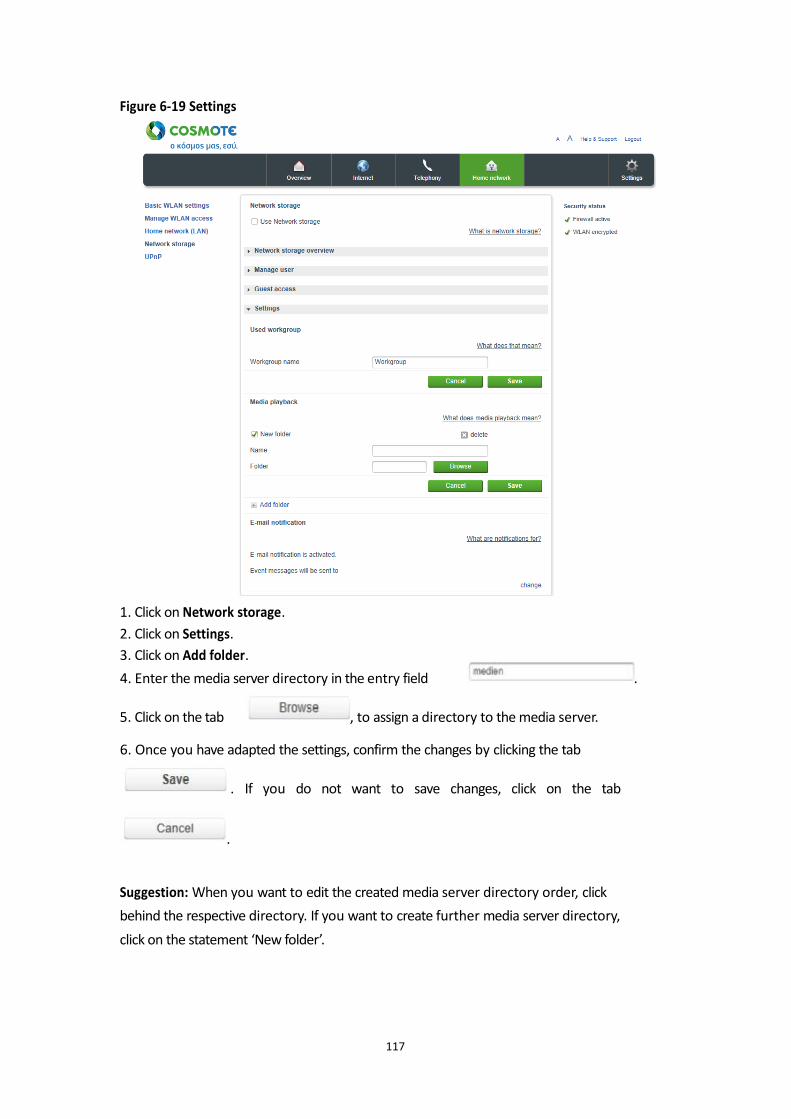
Figure 6-19 Settings
1. Click on Network storage.
2. Click on Settings.
3. Click on Add folder.
4. Enter the media server directory in the entry field .
5. Click on the tab , to assign a directory to the media server. 6. Once you have adapted the settings, confirm the changes by clicking the tab
. If you do not want to save changes, click on the tab
.
Suggestion: When you want to edit the created media server directory order, click
behind the respective directory. If you want to create further media server directory,
click on the statement ‘New folder’.
117

E-Mail messages
Your Speedport can regularly update you about important incidences in your
network storage via E-mail (i.e. critical storage status, data backup and folder
synchronization events).
118
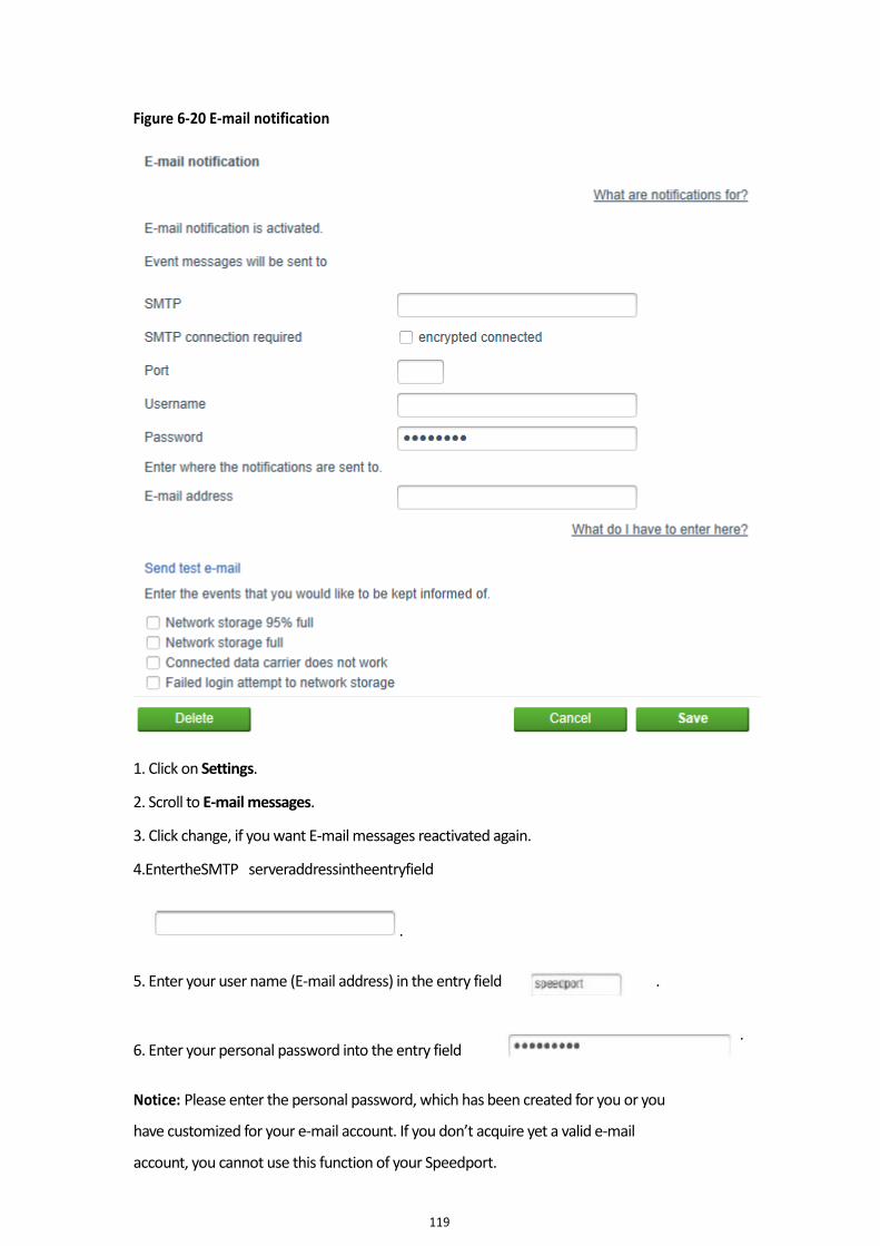
Figure 6-20 E-mail notification
1. Click on Settings.
2. Scroll to E-mail messages.
3. Click change, if you want E-mail messages reactivated again.
4.EntertheSMTP serveraddressintheentryfield
.
5. Enter your user name (E-mail address) in the entry field
6. Enter your personal password into the entry field
.
.
Notice: Please enter the personal password, which has been created for you or you
have customized for your e-mail account. If you don’t acquire yet a valid e-mail
account, you cannot use this function of your Speedport.
119
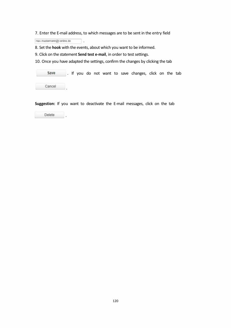
7. Enter the E-mail address, to which messages are to be sent in the entry field
.
8. Set the hook with the events, about which you want to be informed.
9. Click on the statement Send test e-mail, in order to test settings.
10. Once you have adapted the settings, confirm the changes by clicking the tab
. If you do not want to save changes, click on the tab
.
Suggestion: If you want to deactivate the E-mail messages, click on the tab
.
120
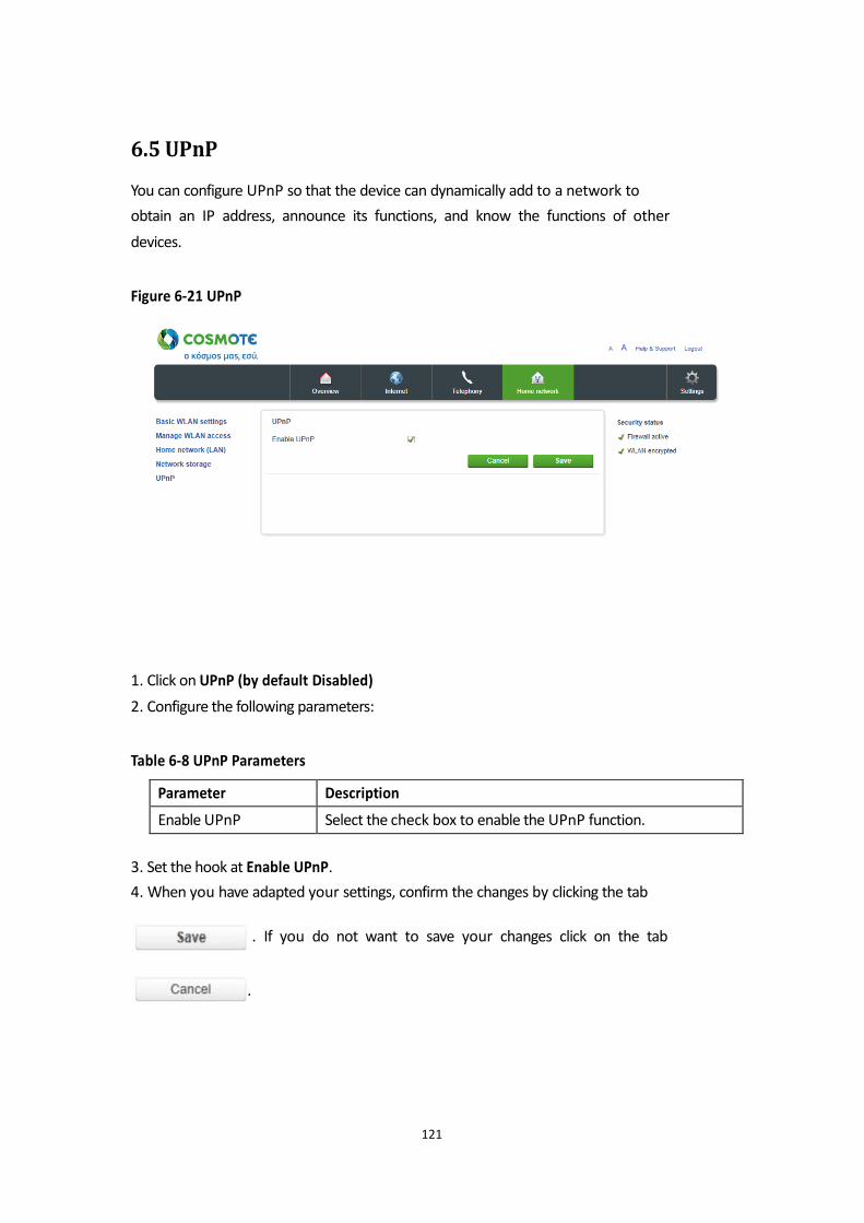
6.5 UPnP
You can configure UPnP so that the device can dynamically add to a network to
obtain an IP address, announce its functions, and know the functions of other
devices. Figure 6-21 UPnP
1. Click on UPnP (by default Disabled)
2. Configure the following parameters: Table 6-8 UPnP Parameters
3. Set the hook at Enable UPnP.
4. When you have adapted your settings, confirm the changes by clicking the tab
. If you do not want to save your changes click on the tab
.
121
Parameter Description
Enable UPnP Select the check box to enable the UPnP function.

Chapter 7 Telephony
The telephony service is not available.
Speedport Plus supports internet telephony with up to 2 analogue telephones. Notice: Please note, that Telephony is available only with Internet connectivity. Notice: In case of power failure telephony is not supported.
123
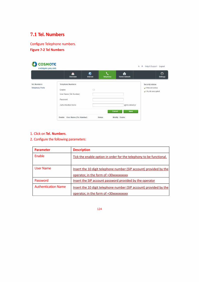
7.1 Tel. Numbers
Configure Telephone numbers.
Figure 7-2 Tel Numbers
1. Click on Tel. Numbers.
2. Configure the following parameters:
124
Parameter Description
Enable Tick the enable option in order for the telephony to be functional.
User Name Insert the 10 digit telephone number (SIP account) provided by the
operator, in the form of +30xxxxxxxxxx
Password Insert the SIP account password provided by the operator
Authentication Name Insert the 10 digit telephone number (SIP account) provided by the
operator, in the form of +30xxxxxxxxxx

39. When you have finished configuring your settings, confirm the changes by clicking
on. ?????
If you do not want to save your changes click on ?????
.
125
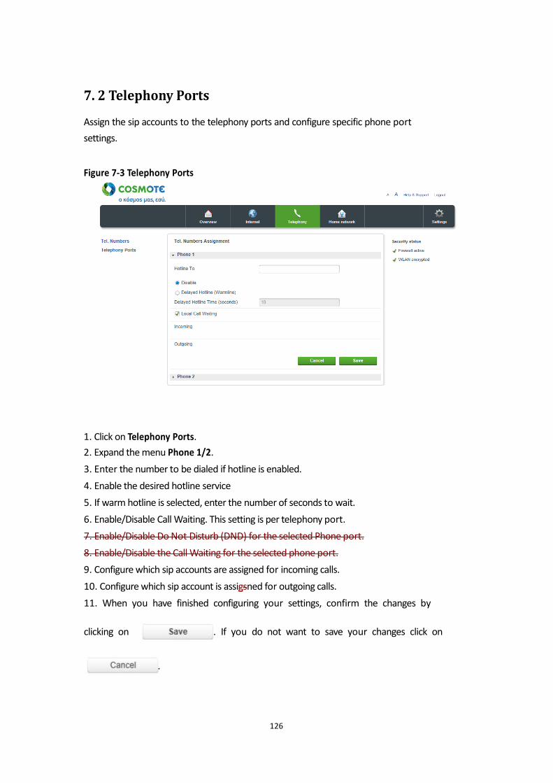
7. 2 Telephony Ports
Assign the sip accounts to the telephony ports and configure specific phone port
settings. Figure 7-3 Telephony Ports
1. Click on Telephony Ports.
2. Expand the menu Phone 1/2.
3. Enter the number to be dialed if hotline is enabled.
4. Enable the desired hotline service
5. If warm hotline is selected, enter the number of seconds to wait.
6. Enable/Disable Call Waiting. This setting is per telephony port.
7. Enable/Disable Do Not Disturb (DND) for the selected Phone port.
8. Enable/Disable the Call Waiting for the selected phone port.
9. Configure which sip accounts are assigned for incoming calls.
10. Configure which sip account is assigsned for outgoing calls.
11. When you have finished configuring your settings, confirm the changes by
clicking on . If you do not want to save your changes click on
.
126

136
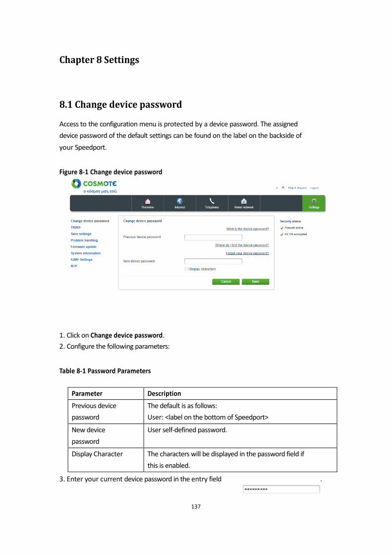
Chapter 8 Settings
8.1 Change device password
Access to the configuration menu is protected by a device password. The assigned
device password of the default settings can be found on the label on the backside of
your Speedport. Figure 8-1 Change device password
1. Click on Change device password.
2. Configure the following parameters: Table 8-1 Password Parameters
3. Enter your current device password in the entry field .
137
Parameter Description
Previous device
password
The default is as follows:
User: <label on the bottom of Speedport>
New device
password
User self-defined password.
Display Character The characters will be displayed in the password field if
this is enabled.
4. Enter your own personal device password in the entry field
.
Notice: The personal password consists of 8 to 12 permitted characters (uppercase letters, lowercase letters,
numbers and special characters) and more than one type of characters must be included. 5. Once you have adapted the settings, confirm the changes by clicking the tab
. If you do not want to save changes, click on the tab
.
Forgot device password
If you have forgotten your personal device password and cannot access anymore the
user interface of your Speedport, you have to reset your Speedport to delivery
status.
1. Push for at least five seconds with a thin item in the opening on the backside of
your Speedport (labeled with Reset).
Notice: All previous user-configured settings will be lost!
2. Now use the preset device password on the type label printed on the bottom of
your Speedport to log in again.
138
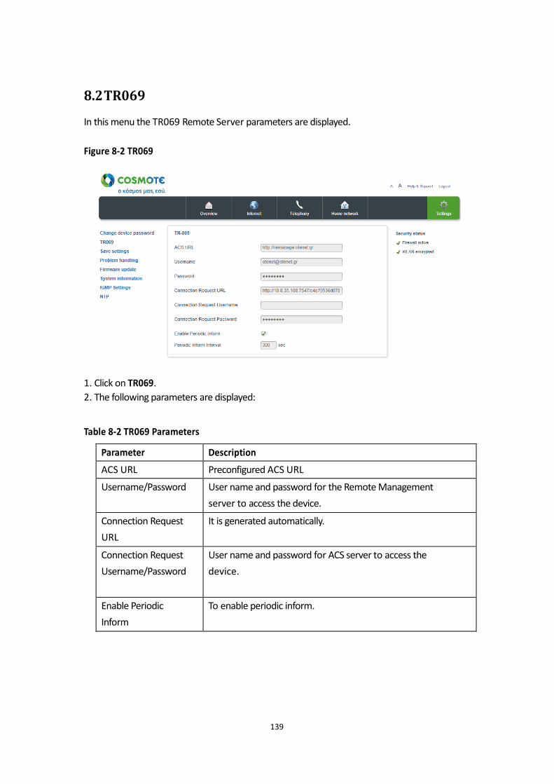
8.2 TR069
In this menu the TR069 Remote Server parameters are displayed.
Figure 8-2 TR069
1. Click on TR069.
2. The following parameters are displayed: Table 8-2 TR069 Parameters
139
Parameter Description
ACS URL Preconfigured ACS URL
Username/Password User name and password for the Remote Management
server to access the device.
Connection Request
URL
It is generated automatically.
Connection Request
Username/Password
User name and password for ACS server to access the
device.
Enable Periodic
Inform
To enable periodic inform.

141
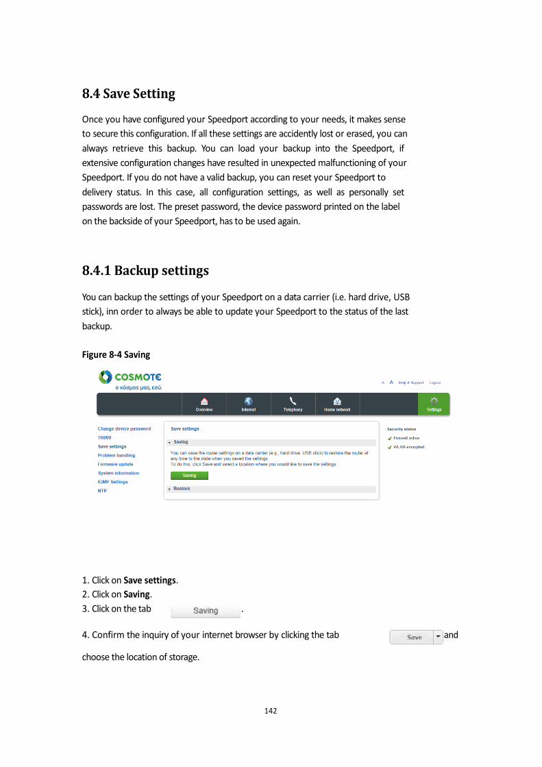
8.4 Save Setting
Once you have configured your Speedport according to your needs, it makes sense
to secure this configuration. If all these settings are accidently lost or erased, you can
always retrieve this backup. You can load your backup into the Speedport, if
extensive configuration changes have resulted in unexpected malfunctioning of your
Speedport. If you do not have a valid backup, you can reset your Speedport to
delivery status. In this case, all configuration settings, as well as personally set
passwords are lost. The preset password, the device password printed on the label
on the backside of your Speedport, has to be used again.
8.4.1 Backup settings
You can backup the settings of your Speedport on a data carrier (i.e. hard drive, USB
stick), inn order to always be able to update your Speedport to the status of the last
backup.
Figure 8-4 Saving
1. Click on Save settings.
2. Click on Saving.
3. Click on the tab .
4. Confirm the inquiry of your internet browser by clicking the tab choose the location of storage.
142
and
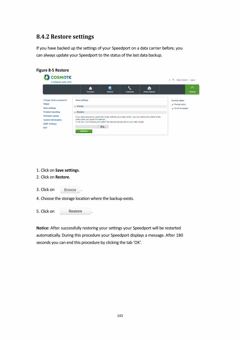
8.4.2 Restore settings
If you have backed up the settings of your Speedport on a data carrier before, you
can always update your Speedport to the status of the last data backup. Figure 8-5 Restore
1. Click on Save settings.
2. Click on Restore.
3. Click on .
4. Choose the storage location where the backup exists.
5. Click on .
Notice: After successfully restoring your settings your Speedport will be restarted
automatically. During this procedure your Speedport displays a message. After 180
seconds you can end this procedure by clicking the tab ‘OK’.
143
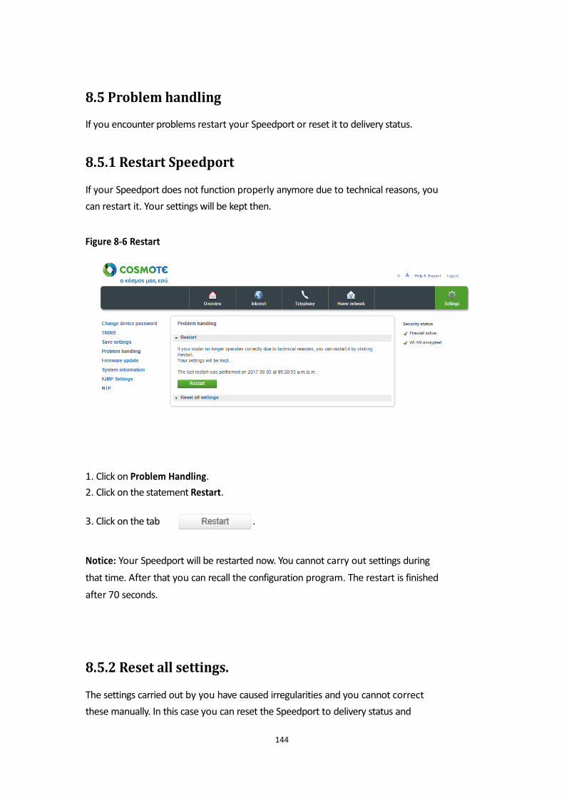
8.5 Problem handling
If you encounter problems restart your Speedport or reset it to delivery status.
8.5.1 Restart Speedport
If your Speedport does not function properly anymore due to technical reasons, you
can restart it. Your settings will be kept then. Figure 8-6 Restart
1. Click on Problem Handling.
2. Click on the statement Restart.
3. Click on the tab .
Notice: Your Speedport will be restarted now. You cannot carry out settings during
that time. After that you can recall the configuration program. The restart is finished
after 70 seconds.
8.5.2 Reset all settings.
The settings carried out by you have caused irregularities and you cannot correct
these manually. In this case you can reset the Speedport to delivery status and
144
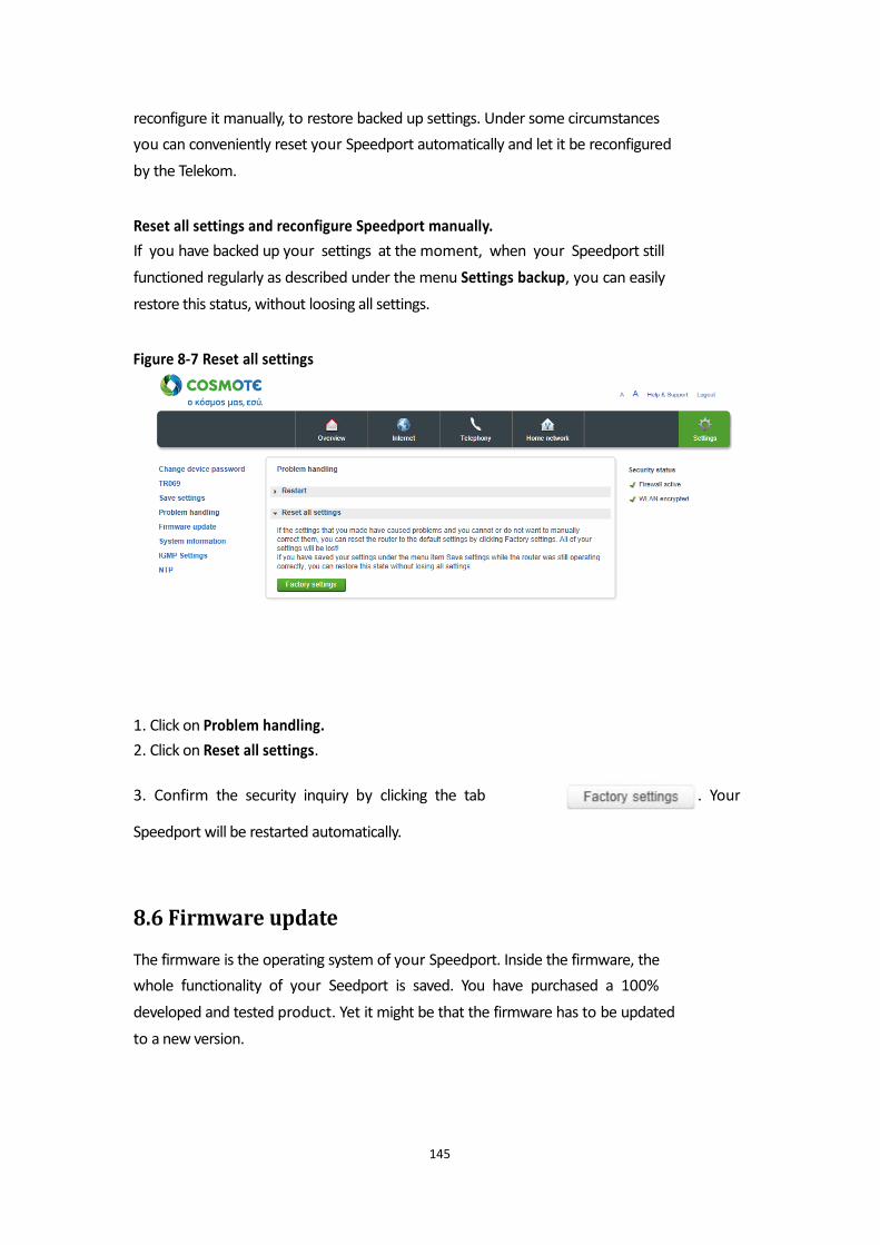
reconfigure it manually, to restore backed up settings. Under some circumstances
you can conveniently reset your Speedport automatically and let it be reconfigured
by the Telekom. Reset all settings and reconfigure Speedport manually.
If you have backed up your settings at the moment, when your Speedport still
functioned regularly as described under the menu Settings backup, you can easily
restore this status, without loosing all settings. Figure 8-7 Reset all settings
1. Click on Problem handling.
2. Click on Reset all settings.
3. Confirm the security inquiry by clicking the tab . Your Speedport will be restarted automatically.
8.6 Firmware update
The firmware is the operating system of your Speedport. Inside the firmware, the
whole functionality of your Seedport is saved. You have purchased a 100%
developed and tested product. Yet it might be that the firmware has to be updated
to a new version.
145
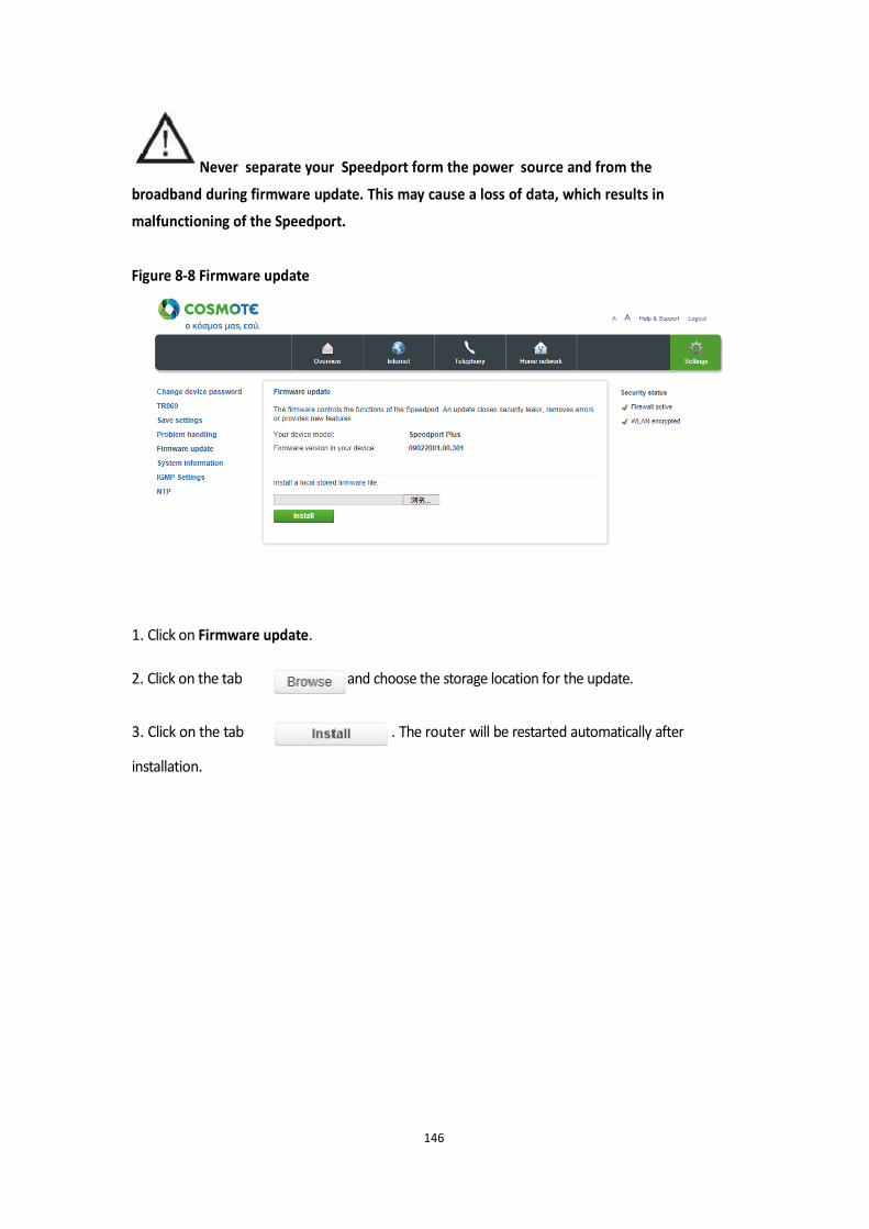
Never separate your Speedport form the power source and from the
broadband during firmware update. This may cause a loss of data, which results in
malfunctioning of the Speedport. Figure 8-8 Firmware update
1. Click on Firmware update.
2. Click on the tab
3. Click on the tab
and choose the storage location for the update.
. The router will be restarted automatically after
installation.
146
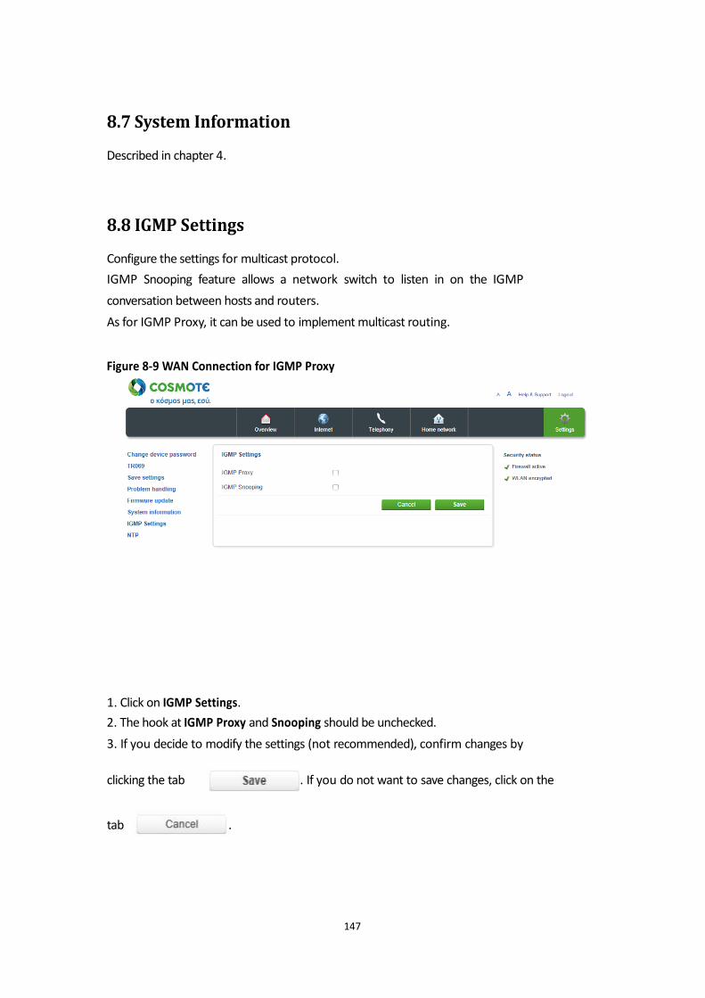
8.7 System Information
Described in chapter 4.
8.8 IGMP Settings
Configure the settings for multicast protocol.
IGMP Snooping feature allows a network switch to listen in on the IGMP
conversation between hosts and routers.
As for IGMP Proxy, it can be used to implement multicast routing. Figure 8-9 WAN Connection for IGMP Proxy
1. Click on IGMP Settings.
2. The hook at IGMP Proxy and Snooping should be unchecked.
3. If you decide to modify the settings (not recommended), confirm changes by
clicking the tab . If you do not want to save changes, click on the
tab .
147

8.9 NTP
Configure the settings for Network Time Server. The device will contact a Network
Time Server at regular intervals and update its internal timer. Figure 8-10 NTP
1. Click on NTP.
2. Enter your primary NTP server address in the entry field (preconfigured)
.
3. Enter your secondary NTP server address in the entry field (preconfigured)
.
4. Set the hook at Enable Daylight Saving time, if your location is currently using
Daylight Saving.
5. Once you have modified the settings, confirm the changes by clicking the tab
. If you do not want to save changes, click on the tab
.
148
Reset to delivery status (Reset)
Your device contains private data, which could harm, once they get public. These
data may be plug recognition supplied by your provider and your personal password.
With these data strangers can surf the internet, check E-mails and carry out other
security sensitive processes at your expenses. That is why you have to carry out a
reset before you give your device for example for reparation or maintenance to third
parties. The reset to delivery status is also necessary, if you have forgotten your personal
password and you have no more access to the configuration program. In this case
you have to completely reconfigure your device as follows: 1. Your Speedport has to be connected to the power source.
2. Use a thin pointed object to press for at least five seconds into the opening on the
backside of your Speedport labeled with Reset.
3. Wait 180 seconds, before disconnecting your Speedport from the power source.
Now all data are erased and replaced by the delivery status data. Now you can
unhesitatingly hand over your Speedport to someone else.
If you want to check, whether all data are erased, try out if the password has been
reset to default settings (Device password on the type label on the backside of your
Speedport). If the password has been reset, all other data have been erased as well.
Notice: Please note that after a reset to the delivery status the WLAN name (SSID)
and the WLAN key are reset to the default settings. These are the data, which are
entered on the type label on the backside of your Speedport or in the included
WLAN device passport. If you give your Speedport to others, this information is
accessible as well for other.
149
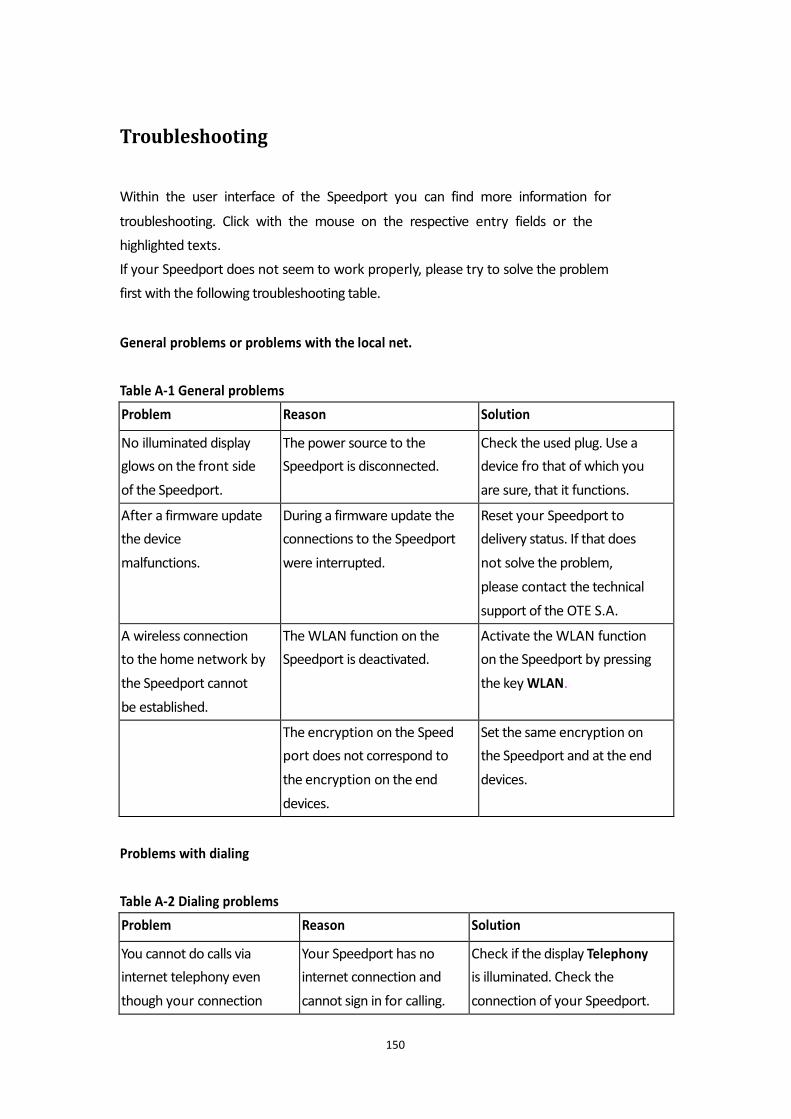
Troubleshooting
Within the user interface of the Speedport you can find more information for
troubleshooting. Click with the mouse on the respective entry fields or the
highlighted texts.
If your Speedport does not seem to work properly, please try to solve the problem
first with the following troubleshooting table. General problems or problems with the local net. Table A-1 General problems Problems with dialing Table A-2 Dialing problems
150
Problem Reason Solution
No illuminated display
glows on the front side
of the Speedport.
The power source to the
Speedport is disconnected.
Check the used plug. Use a
device fro that of which you
are sure, that it functions.
After a firmware update
the device
malfunctions.
During a firmware update the
connections to the Speedport
were interrupted.
Reset your Speedport to
delivery status. If that does
not solve the problem,
please contact the technical
support of the OTE S.A.
A wireless connection
to the home network by
the Speedport cannot
be established.
The WLAN function on the
Speedport is deactivated.
Activate the WLAN function
on the Speedport by pressing
the key WLAN.
The encryption on the Speed
port does not correspond to
the encryption on the end
devices.
Set the same encryption on
the Speedport and at the end
devices.
Problem Reason Solution
You cannot do calls via
internet telephony even
though your connection
Your Speedport has no
internet connection and
cannot sign in for calling.
Check if the display Telephony
is illuminated. Check the
connection of your Speedport.
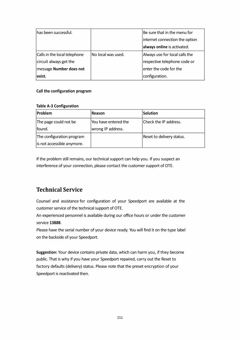
Call the configuration program Table A-3 Configuration If the problem still remains, our technical support can help you. If you suspect an
interference of your connection, please contact the customer support of OTE.
Technical Service
Counsel and assistance for configuration of your Speedport are available at the
customer service of the technical support of OTE.
An experienced personnel is available during our office hours or under the customer
service 13888.
Please have the serial number of your device ready. You will find it on the type label
on the backside of your Speedport. Suggestion: Your device contains private data, which can harm you, if they become
public. That is why if you have your Speedport repaired, carry out the Reset to
factory defaults (delivery) status. Please note that the preset encryption of your
Speedport is reactivated then.
151
has been successful. Be sure that in the menu for
internet connection the option
always online is activated.
Calls in the local telephone
circuit always get the
message Number does not
exist.
No local was used. Always use for local calls the
respective telephone code or
enter the code for the
configuration.
Problem Reason Solution
The page could not be
found.
You have entered the
wrong IP address.
Check the IP address.
The configuration program
is not accessible anymore.
Reset to delivery status.
Disposal of old devices
Once your Speedport is disused, bring the old device to a collecting
point of your local public waste authorities (i.e. junk dealer). The symbol on the left
indicates that the device is to be disposed of separately from the household trash.
According to the laws of disposal for electrical and electronic equipment owners of
old devices are obliged to have old electrical and electronical devices disposed of in
separated waste. Please help and contribute to the environmental protection by not
disposing of the old device in the household trash. Note for the recycler: The date of production or bringing into circulation is stated on
the type label in accordance with DIN EN 60062, No. 5. Your device contains secret data, which could harm you if they become public. So if
you for example want to have your device repaired reset it back to delivery status.
Please note that the preset encryption of the data is active again then.
The Speedport Plus equipment is available exclusively in Greece.
OTE SA
Kifisias 99, Ave
151 24, Maroussi, Athens
Greece
152