some basic microwave phase shift equations - … · some basic microwave phase shift equations ......
TRANSCRIPT
RADIO SCIENCE Journal of Research, NBS/USNC- URSI Vol. 68D No.4, April 1964
Some Basic Microwave Phase Shift Equations Robert W. Beatty
Contribution from the Radio Standards Laboratory, National Bureau of Standards, Boulder, Colo.
(R eceived November 14,1963)
The phase di fferences between terminal variables (voltage, current, ar t raveli ng wave types) at the output with respect to similar ones at the input of a 2-port are expressed in te rms of the scattering coefficients of t he 2-port and of the reflection coefficients of t he system into which it is inserted.
A variety of phase s hifts may be defined for a give n 2-port, depending upon which of the termm al van a bles a rc co nSIdered, whether or not generator :Lnd load refl ect ion coefficients are assumed to vanish , and in wh ich direction the 2-port has bccn inserted into the syste m.
It is shown that a reaso na ble e hoice for one of the two " characterist ic" phase' s h ifts of a 2-por t is lf2J, the ar'gu ment of S 2J, one of the scattering coeffici ents. It [ollo \l's that t he other "characteristic" pha c shift is lfr2. The co rTesponding change in characteristic phase shift for variable phase shi fter::> is t he change in either "'21 or h 2 (\\'hi chever is appropriate) from the i nitial to the fina l setting .
. Ideal phase s hifters ar~ discussed , a nd expressio ns for t Il(' change in output level of var-r a bl e phase s hlfk rs a re gIven. The Importance of us ing a llonreflectin rr syste m in phase shift meas lIrements i::> emphasi~ed. "
1. Introduction
The m easurelll cllL of Lhe p hasc shift in g pl'operLies of microwave devices llfLS received relatively li ttle fL Ltentioll, but is becoilllng more important. On e canno t fiJld a refcreJice to microwave phase shilL m easurements in any of the well-knowll texts on microwave measurements that have been published to date. However , evidences of in creasin g inl erest include the recent development by commercial organizati.ons of several differen t s wep t J'requell cy systems for microwave phase shift measuremenls. In addition, papers on this subj ect have been surveyed in a recen t article by R. A. Sparks [1963].
It seems appropriate at this time t.o examine concepts of microwave phase shift in order to clefLrly
1
b1 rG r l a1
i1
5 11
VI 52 1
°1
understand what types of phfLsc shift may occur ",nd how they may be descri bed in a q uanLiLaLivc WfLy.
Specifically, it is p1"OpO cd in this paper to presen t expressio ns relatin g Lile phase shifLs associated with fL !2-port to Lhe sCfLt Lcl'in g coefficients of thfLt 2-port fLnd the reflecLion cocffLcients of Lhc system in which Lhe 2-port is COl1n ected.
2 . General
Several Lypes of phAse shift of 2-ports may be considered, as will be shown wiLh reference to figure l.
The usefuln ess of thc diil'erent types of phase shift considered will depen d upon what types of
2
° r -~ L -b2
i2
5 12
V2 5 22
°2
1 2
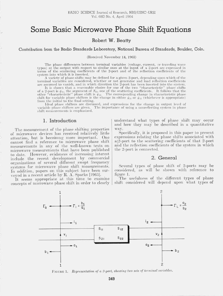
FIGURE 1. Representation of a 2-port, showing two sets of terminal vw·iabies .
349

detectors are used in a measurement of phase difference and whether they respond t o wave amplitudes or generalized voltage and current. (An electric field pro be in a slotted line would respon d to v, for example.)
In figure 1, the terminal surfaces 1- 1, and 2- 2, in the waveguide leads of the 2-port, are the places where the complex amplitudes a and b of the incident and emergent voltage waves, and v and i, the generalized voltage and current, [Kerns, 1949] are to be considered. The assumptions inherent in this representation of a 2-port, such as single-mode propagation in the lossless waveguide leads have been set forth by D. M. Kerns [1949 and 1951].
The relationship between the two sets of terminal variables is as follows
v= a+ b }
Zoi= a - b (1)
The amplitude be of the generator wave, a], b], and r e are related by the followin g equation:
(2)
One can consider the phase shift of the 2-port to be the difference in phase between Vz and VI, between iz and ii' between bz and aJ, or between b2 and be, for example. "The phase shift of a 2-port" may, therefore, be a misleading and ambiguous expression, since it seems to imply either that there is only one, or that all phase shifts of a given 2-port are the same. In the following, equations will be given to show how these various phase shifts will differ in general, and w1der what conditions some of them may be the same.
The equations will be given for the case of a linear 2-port (which may be nonreciprocal) inserted into a system in such a direction that a generator feeds arm 1 and the load terminates arm 2. For simplicity, the symbols such as t/;v for phase shift do not in dicate that this direction has been chosell. One can easily obtain the corresponding phase shift for the opposite direction of energy flow thru the 2-port by interchanging subscripts 1 and 2 in the equations.
If the phase shifter is a reciprocal one, the condition Z01821 = Z0281 2 will hold, where Z01 and Z02 are the characteristic impedances of the w:weguide leads 1 an d 2 of the 2-port. Very often , Z01 = Z02, an d the reciprocity condition is written 82]= 8 12, This condition may be substituted into the phase shift equations in order to reduce the number of variables by one for a reciprocal 2-port.
3. Phase Shift Equations
The derivation of the following expressions r or phase shift will not be given , as they follow from straightforward algebraic manipulation iof eqs (1 ) and (2) and the scattering equations of the 2-por t.
350
bl= 811al + 812a2 ~ . b2= 8 z1al + 8 2Zaz j
3.1 . Phase Shift of v
(3)
The phase shift of v, denoted by t/;., may be written as follows
This phase shift depends upon the reflection coefficient of the load as well as upon the characterist ics of the 2-port. When the load is nonrefiecting,
(5)
If one employs the impedance matrix instead of the scattering matrix of the 2-port, the equations corresponding to (4) an d (5) are
(6)
and
(7)
where normalized impedances are used. For an open-circuited phase shifter,
(8)
3.2. Phase Sh ift of i
Proceeding in a similar way,
When the load is nonreflecting,
(10)
If one employs the admitlance matrix in stead of the scatterin g m airix of the 2-port, the equations corresponding to (9) and (10) are
and
(12)
where normalized adm.ittances are used.
J '>
I
For a short-circuited phase shifter ,
(13)
3.3. Phase Difference Between b 2 and a [
One can see by inspection of the scattering equations and figure 1 that
(21)
The fU'st or these components is given by (14), and the second follows from subsequent inspection or (7).
(22)
(14) Thus, one obtains
When the load is nonrefiecting,
[1/'b2.al]rL =O = arg 8 2[= 1/' 21 ' (15)
This phase shift is particularly interesting because it is simply the phase 1/'21 of t he scatterin g coefficien t 82b a Iundamen tal characteristic of the 2-port.
3.4. Phase Difference between b 2 and b e
It is clear from (2) that t he generator wave be does not, in general , have the sam e amplitude as the wave incident upon the 2-port in arm 1. Th e phase difference between b2 and be is therefore of interest and may be written
or
This phase shift depenns upon t he r efl ection coeffi cients of generator and load as weI] as upon Lhe scatterin g coeffi cients of t he 2-port. Wh en only the load is nonrefiecting,
(18)
Wh en only the generator is nonreflecting,
(19)
Wil en both generator and load are nonreflecting,
It is observed that this is the same result as (15) a nd is of specifl,l interest for the same reason t hat (15) is of' in terest.
The phase difference between b2 and bG may be expressed in terms of two components, (1) the phase difference between a[ and be, and (2) the phase difference between b2 and a[ as follows .
351
1/'b2,be=1/'2[- arg (I-S22r L)-arg (l- r er ). (23)
This latter expression shows clearly how reA ections rrom the generator and 10f1d Cf1n affect 1/'b2' bC'
Other phase differen ces such as between b2 and b" a 2 and aI, b2, and VI, etc., could be considered, but m'e perhaps of less inter est thf1n the above examples. Writin g or equfltion s 1'01' these phase differences would not be diffi cult, if they wer e desired.
4. Differential Phase Shift
Wh en variable phase s hif ters are adjusted, one is interested in a change produ ced in th e phase of 1'2 or b2 at the output waveguide lead of the 2-port as showll in figure 1.
For t he PU~'poses or an ,tlysis , it is con venien L to r egard a variable ph ase shif ter adjustment as though one r emoved an iniLial pllilse shifter and subsLitu ted H fin ftl phase shift er , even though the vftriftble pllftse s hift er r emains in t he system ilt all Limes . Using fronL superscripLs i and .f to denote initial fi nd unal conditions, r espectively, it C,l,Il be s hown as fol~ows that the chftn ge in phase o[ V2 produced by ft gIven chano'e or fl variable phase shifter is Lhe sam e as the cOlTe~ponclin g change in phase of b2 • Writing the chftnge in phase
(24)
(25)
One can now obtain an expression for the differential phase shift , using [
and (25), and assuming thftt there is no change in be, r e, or rL ·
1 This follows from m anipulation of (2) and (3), substi tuting a,=b,I"L.
The differential phase shift is
i11/; - . [1S 21 • (l-iSllrG)(I - iS22rL) _iSI2iS21rGrL] . - aIg iS21 (1-1s11rG)(I-1S22rrJ-1S1lS21rGrL
(27) If only t.he generator is nonreflecting,
(28)
If only the load is nonreflecting,
(29)
If both generator and load are nonreflecting,
(30)
5. Characteristic Phase Shift
The foregoing equations have served t.o illustrate that the phase differences considered will in genernl depen d not only upon the characteristics of t.he 2-port, but nlso upon the characteristics of the load, and in some cases also upon the characteristics of the generator.
If Ol1e is interested in a phase difference which depends only upon characteristics of the 2-port, then (5), (10) , (15), and (20) can be considered . Of these, (15) and (20) are simplest. Thus it would seem desirable to select 1/;21 as one of the characteristic phase shifts of a 2-port. (The other would be 1/;12') It would be defuled 2 as the phase difference between b2 and bG when nom-eflecting generator and load fire connected to arms 1 and 2, respectively, of the 2-port.
The differential phfise shift of a 2-port in a nonreflecting system as given by (30) is then simply the differen tial characteristic phase differen ce, as defllJed above.
"\Then phase differences of 2-ports are mensured lllder different source or load conditions. different results will be expected. The discrepandes can be called mismatch errors, which can be evaluated by reference to t he foregoing equations.
6 . An Ideal Phase Shifter
The concept of an ideal phase shifter is useful for comparison purposes in evaluating the performance of actual phase shifters. Such a phase shifter would be nonreflecting (Sll = S22= 0) , and lossless, but could be nonreciprocal. Consequently
2 This definition is in harmony with thut given in IRE Standards on Antennas and Waveguid es: Wavegu ide and waveguide component measurements , 1959, Proc. IRE 47, No.4, 568- 582.
One notes that the phase shifts of an ideal phase shifter more closely approach 1/;21, than one which is not ideal, even if generator and load reflections are present. For example,
(31)
(32)
(33)
and (34)
The differential phase shift of an idcal phase shifter IS
(35)
It is seen that the use of an ideal phase shifter does not obviate the need for a nonreflecting system, if the characteristic phase shift is to be produced.
In an ideal situation, the output level is not chf).nged when the phase shifter is adjusted. However, it can be seen by application of (26) that the change in level of either V2 or b2 expre..<;sed in decibels is
[ ib2[ t:.L= 20 10glO 162
= 20 10glo [iS21 . ( l -fSllra)(I - fS22rL) _ 1S1lS21r Gr L[. 1S21 (1- 'Sllr G) (1 -'S22rL) -'SI2'S21r Gr L
(36)
Even with an ideal phase shirter , a change in level will occur, given by
i1L (for ideal phase shifter ) = 20 loglo
11-rGrL ei(111'"1 +1f I2 J[ . (37) 1- r Gr LCi (' f2!+'fI2)
One can see from the above that there would be no change in level from an ideal phase shifter in a nonreflecting system (r G = r L = 0), but that such a change in level would generally occlli' if the phase shifter were not ideal.
7 . Conclusions
It hn,s been shown that one can reasonably choose either 1/;21, the argument of S21, or ""1 2, the argument. of S12, as the ehamcteristic phase shift of a 2-port. For a variable phase shifter, the characteristic differential phase shift i11/; equals the change in 1/;21 between initial and mal settings.
In measuring these quantities, it is important to insert the phase shifter into nonreflecting systems
352
-;'

r
(rC= rL = o), and in usin g the phase shifter thereafter, it is no less important to duplicate Lh ese conditions. AllY deviation from these conditions will result in a mismatch error , and these hfwe becn analyzed [Scharer, 1960] for some types or measUl'CJll cn t systems.
The use or an ideal phase shiJter which is lossless alld nonreHecting does not obviate the need for a nonreflectin g system in phase shift measurements, al though the mismatch errors will usually be sm aller ir thc phase shifter is ideal. It was show11 that there will be no change in the output level of an ideal variable phase shifter when operated in a nonreflecting sys tem, but some change can be expected if the system has reflections .
Constructive criticism an d suggestions for improving the presentation were given by David M.
353
K el'll s of NBS and Helmut M. Altschuler of the Polytechnic Institute of Brooklyn. The encouragement given by G. E. Schafer of NBS is also gratefully ackll owledgcd.
8 . References
Kerns, David M. C\I[ay 1949), Basis of t he appli cation of netwo rk equations to waveg uide problems, J. Res. NBS 42, No.5, 515- 540, RP1990 .
Kerns, David M. (Apr. 1951), Analys is of symmetrical waveguid e junctions, J . R es. NBS 46 , No.4, 267- 282, RP2195.
Sc hafer, George E. (Nov. 1960), Mismatch errors in microwave phase shift measurements, IRE Trans. on MTT 8, No.6,617- 622.
Sparks, R ichard A. (Jan. 1963), Microwave phase measurements, Microwaves 2, No.1 , 14- 25.
(Paper 68D4-352)