solution - testbanku.eu · solution - testbanku.eu ... e # # #
TRANSCRIPT

1
© 2017 Pearson Education, Inc., Hoboken, NJ. All rights reserved. This material is protected under all copyright laws as they currently exist. No portion of this material may be reproduced, in any form or by any means, without permission in writing from the publisher.
SolutionSolutionSupport Reactions: We will only need to compute Cy by writing the moment equation of equilibrium about B with reference to the free-body diagram of the entire shaft, Fig. a.
a+ ΣMB = 0; Cy(8) + 400(4) - 800(12) = 0 Cy = 1000 lb
Internal Loadings: Using the result for Cy, section DE of the shaft will be considered. Referring to the free-body diagram, Fig. b,
S + ΣFx = 0; NE = 0 Ans.
+ c ΣFy = 0; VE + 1000 - 800 = 0 VE = -200 lb Ans.
a+ ΣME = 0; 1000(4) - 800(8) - ME = 0
ME = - 2400 lb # ft = - 2.40 kip # ft Ans.
The negative signs indicates that VE and ME act in the opposite sense to that shown on the free-body diagram.
1–1.
The shaft is supported by a smooth thrust bearing at B and a journal bearing at C. Determine the resultant internal loadings acting on the cross section at E.
A E DB C
4 ft
400 lb800 lb
4 ft 4 ft 4 ft
Ans: NE = 0, VE = -200 lb, ME = - 2.40 kip # ft
This w
ork is
prote
cted b
y Unit
ed S
tates
copy
right
laws
and i
s prov
ided s
olely
for th
e use
of in
struc
tors i
n tea
ching
their c
ourse
s and
asse
ssing
stud
ent le
arning
. Diss
emina
tion
or sa
le of
any p
art of
this
work (in
cludin
g on t
he W
orld W
ide W
eb)
will de
stroy
the i
ntegri
ty of
the w
ork an
d is n
ot pe
rmitte
d.
Full file at https://testbanku.eu/Solution-Manual-for-Mechanics-of-Materials-10th-Edition-by-Hibbeler

2
© 2017 Pearson Education, Inc., Hoboken, NJ. All rights reserved. This material is protected under all copyright laws as they currently exist. No portion of this material may be reproduced, in any form or by any means, without permission in writing from the publisher.
SolutionSolution(a)
+S ΣFx = 0; Na - 500 = 0
Na = 500 lb Ans.
+T ΣFy = 0; Va = 0 Ans.
(b)
R+ ΣFx = 0; Nb - 500 cos 30° = 0
Nb = 433 lb Ans.
+Q ΣFy = 0; Vb - 500 sin 30° = 0
Vb = 250 lb Ans.
1–2.
Determine the resultant internal normal and shear force in the member at (a) section a–a and (b) section b–b, each of which passes through the centroid A. The 500-lb load is applied along the centroidal axis of the member.
30�
A
ba
b a
500 lb500 lb
Ans: (a) Na = 500 lb, Va = 0,(b) Nb = 433 lb, Vb = 250 lb
This w
ork is
prote
cted b
y Unit
ed S
tates
copy
right
laws
and i
s prov
ided s
olely
for th
e use
of in
struc
tors i
n tea
ching
their c
ourse
s and
asse
ssing
stud
ent le
arning
. Diss
emina
tion
or sa
le of
any p
art of
this
work (in
cludin
g on t
he W
orld W
ide W
eb)
will de
stroy
the i
ntegri
ty of
the w
ork an
d is n
ot pe
rmitte
d.
Full file at https://testbanku.eu/Solution-Manual-for-Mechanics-of-Materials-10th-Edition-by-Hibbeler

3
© 2017 Pearson Education, Inc., Hoboken, NJ. All rights reserved. This material is protected under all copyright laws as they currently exist. No portion of this material may be reproduced, in any form or by any means, without permission in writing from the publisher.
SolutionSolutionSupport Reaction:
a+ ΣMA = 0; NB(9 sin 30°) -12
(900)(9)(3) = 0
NB = 2700 lb
Equations of Equilibrium: For section b–b
S + ΣFx = 0; Vb - b +12
(300)(3) sin 30° - 2700 = 0
Vb - b = 2475 lb = 2.475 kip Ans.
+ c ΣFy = 0; Nb - b -12
(300)(3) cos 30° = 0
Nb - b = 389.7 lb = 0.390 kip Ans.
a+ ΣMC = 0; 2700(3 sin 30°)
-12
(300)(3)(1) - Mb - b = 0
Mb - b = 3600 lb # ft = 3.60 kip # ft Ans.
1–3.
Determine the resultant internal loadings acting on section b–b through the centroid C on the beam.
30� 6 ft
3 ft60�
bb900 lb/ft
C
A
B
Ans: Vb - b = 2.475 kip, Nb - b = 0.390 kip, Mb - b = 3.60 kip # ft
This w
ork is
prote
cted b
y Unit
ed S
tates
copy
right
laws
and i
s prov
ided s
olely
for th
e use
of in
struc
tors i
n tea
ching
their c
ourse
s and
asse
ssing
stud
ent le
arning
. Diss
emina
tion
or sa
le of
any p
art of
this
work (in
cludin
g on t
he W
orld W
ide W
eb)
will de
stroy
the i
ntegri
ty of
the w
ork an
d is n
ot pe
rmitte
d.
Full file at https://testbanku.eu/Solution-Manual-for-Mechanics-of-Materials-10th-Edition-by-Hibbeler

4
© 2017 Pearson Education, Inc., Hoboken, NJ. All rights reserved. This material is protected under all copyright laws as they currently exist. No portion of this material may be reproduced, in any form or by any means, without permission in writing from the publisher.
SolutionSolutionSupport Reactions: We will only need to compute By by writing the moment equation of equilibrium about A with reference to the free-body diagram of the entire shaft, Fig. a.
a+ ΣMA = 0; By(4.5) - 600(2)(2) - 900(6) = 0 By = 1733.33 N
Internal Loadings: Using the result of By, section CD of the shaft will be considered. Referring to the free-body diagram of this part, Fig. b,
S + ΣFx = 0; NC = 0 Ans.
+ cΣFy = 0; VC - 600(1) + 1733.33 - 900 = 0 VC = -233 N Ans.
a+ ΣMC = 0; 1733.33(2.5) - 600(1)(0.5) - 900(4) - MC = 0
MC = 433 N # m Ans.
The negative sign indicates that VC acts in the opposite sense to that shown on the free-body diagram.
*1–4.
The shaft is supported by a smooth thrust bearing at A and a smooth journal bearing at B. Determine the resultant internal loadings acting on the cross section at C. A DB
C
900 N
1.5 m
600 N/m
1.5 m1 m1 m1 m
Ans: NC = 0, VC = -233 N, MC = 433 N # m
This w
ork is
prote
cted b
y Unit
ed S
tates
copy
right
laws
and i
s prov
ided s
olely
for th
e use
of in
struc
tors i
n tea
ching
their c
ourse
s and
asse
ssing
stud
ent le
arning
. Diss
emina
tion
or sa
le of
any p
art of
this
work (in
cludin
g on t
he W
orld W
ide W
eb)
will de
stroy
the i
ntegri
ty of
the w
ork an
d is n
ot pe
rmitte
d.
Full file at https://testbanku.eu/Solution-Manual-for-Mechanics-of-Materials-10th-Edition-by-Hibbeler

5
© 2017 Pearson Education, Inc., Hoboken, NJ. All rights reserved. This material is protected under all copyright laws as they currently exist. No portion of this material may be reproduced, in any form or by any means, without permission in writing from the publisher.
SolutionSolution
S + ΣFx = 0; NB = 0 Ans.
+ cΣFy = 0; VB - 12
(48)(12) = 0
VB = 288 lb Ans.
a+ ΣMB = 0; -MB -12
(48)(12)(4) = 0
MB = -1152 lb # ft = -1.15 kip # ft Ans.
1–5.
Determine the resultant internal loadings acting on the cross section at point B.
A C
12 ft3 ft
60 lb/ ft
B
Ans: NB = 0,VB = 288 lb,MB = -1.15 kip # ft
This w
ork is
prote
cted b
y Unit
ed S
tates
copy
right
laws
and i
s prov
ided s
olely
for th
e use
of in
struc
tors i
n tea
ching
their c
ourse
s and
asse
ssing
stud
ent le
arning
. Diss
emina
tion
or sa
le of
any p
art of
this
work (in
cludin
g on t
he W
orld W
ide W
eb)
will de
stroy
the i
ntegri
ty of
the w
ork an
d is n
ot pe
rmitte
d.
Full file at https://testbanku.eu/Solution-Manual-for-Mechanics-of-Materials-10th-Edition-by-Hibbeler

6
© 2017 Pearson Education, Inc., Hoboken, NJ. All rights reserved. This material is protected under all copyright laws as they currently exist. No portion of this material may be reproduced, in any form or by any means, without permission in writing from the publisher.
SolutionSolutionSupport Reactions: Member BC is the two force member.
a+ ΣMA = 0; 45
FBC
(1.5) - 1.875(0.75) = 0
FBC = 1.1719 kN
+ c ΣFy = 0; Ay +45
(1.1719) - 1.875 = 0
Ay = 0.9375 kN
S + ΣFx = 0; 35
(1.1719) - Ax = 0
Ax = 0.7031 kN
Equations of Equilibrium: For point D
S + ΣFx = 0; ND - 0.7031 = 0 ND = 0.703 kN Ans.
+ c ΣFy = 0; 0.9375 - 0.625 - VD = 0 VD = 0.3125 kN Ans.
a+ ΣMD = 0; MD + 0.625(0.25) - 0.9375(0.5) = 0 MD = 0.3125 kN # m Ans.
1–6.
Determine the resultant internal loadings on the cross section at point D.
2 m
D
0.5 m 0.5 m
1.25 kN/m
0.5 m1.5 m
1 m
E B
C
A
F
Ans: ND = 0.703 kN, VD = 0.3125 kN, MD = 0.3125 kN # m
This w
ork is
prote
cted b
y Unit
ed S
tates
copy
right
laws
and i
s prov
ided s
olely
for th
e use
of in
struc
tors i
n tea
ching
their c
ourse
s and
asse
ssing
stud
ent le
arning
. Diss
emina
tion
or sa
le of
any p
art of
this
work (in
cludin
g on t
he W
orld W
ide W
eb)
will de
stroy
the i
ntegri
ty of
the w
ork an
d is n
ot pe
rmitte
d.
Full file at https://testbanku.eu/Solution-Manual-for-Mechanics-of-Materials-10th-Edition-by-Hibbeler

7
© 2017 Pearson Education, Inc., Hoboken, NJ. All rights reserved. This material is protected under all copyright laws as they currently exist. No portion of this material may be reproduced, in any form or by any means, without permission in writing from the publisher.
SolutionSolutionSupport Reactions: Member BC is the two-force member.
a+ ΣMA = 0; 45
FBC (1.5) - 1.875(0.75) = 0
FBC = 1.1719 kN
+ c ΣFy = 0; Ay +45
(1.1719) - 1.875 = 0
Ay = 0.9375 kN
S + ΣFx = 0; 35
(1.1719) - Ax = 0
Ax = 0.7031 kN
Equations of Equilibrium: For point F
+ bΣFx′ = 0; NF - 1.1719 = 0
NF = 1.17 kN Ans.
a + ΣFy′ = 0; VF = 0 Ans.
a+ ΣMF = 0; MF = 0 Ans.
Equations of Equilibrium: For point E
+d ΣFx = 0; NE -35
(1.1719) = 0
NE = 0.703 kN Ans.
+ c ΣFy = 0; VE - 0.625 +45
(1.1719) = 0
VE = -0.3125 kN Ans.
a+ ΣME = 0; -ME - 0.625(0.25) +45
(1.1719)(0.5) = 0
ME = 0.3125 kN # m Ans.
Negative sign indicates that VE acts in the opposite direction to that shown on FBD.
1–7.
Determine the resultant internal loadings at cross sections at points E and F on the assembly.
2 m
D
0.5 m 0.5 m
1.25 kN/m
0.5 m1.5 m
1 m
E B
C
A
F
Ans: NF = 1.17 kN,VF = 0,MF = 0,NE = 0.703 kN,VE = -0.3125 kN,ME = 0.3125 kN # m
This w
ork is
prote
cted b
y Unit
ed S
tates
copy
right
laws
and i
s prov
ided s
olely
for th
e use
of in
struc
tors i
n tea
ching
their c
ourse
s and
asse
ssing
stud
ent le
arning
. Diss
emina
tion
or sa
le of
any p
art of
this
work (in
cludin
g on t
he W
orld W
ide W
eb)
will de
stroy
the i
ntegri
ty of
the w
ork an
d is n
ot pe
rmitte
d.
Full file at https://testbanku.eu/Solution-Manual-for-Mechanics-of-Materials-10th-Edition-by-Hibbeler

8
© 2017 Pearson Education, Inc., Hoboken, NJ. All rights reserved. This material is protected under all copyright laws as they currently exist. No portion of this material may be reproduced, in any form or by any means, without permission in writing from the publisher.
Solution
*1–8.
The beam supports the distributed load shown. Determine the resultant internal loadings acting on the cross section at point C. Assume the reactions at the supports A and B are vertical.
1.5 m 3 m
DCA B
4 kN/m
1.5 m
SolutionSupport Reactions: Referring to the FBD of the entire beam, Fig. a,
a+ ΣMA = 0; By(6) -12
(4)(6)(2) = 0 By = 4.00 kN
Internal Loadings: Referring to the FBD of the right segment of the beam sectioned through C, Fig. b,
S + ΣFx = 0; NC = 0 Ans.
+ c ΣFy = 0; VC + 4.00 -12
(3)(4.5) = 0 VC = 2.75 kN Ans.
a+ ΣMC = 0; 4.00(4.5) -12
(3)(4.5)(1.5) - MC = 0
MC = 7.875 kN # m Ans.
Ans:NC = 0,VC = 2.75 kN,MC = 7.875 kN # m
This w
ork is
prote
cted b
y Unit
ed S
tates
copy
right
laws
and i
s prov
ided s
olely
for th
e use
of in
struc
tors i
n tea
ching
their c
ourse
s and
asse
ssing
stud
ent le
arning
. Diss
emina
tion
or sa
le of
any p
art of
this
work (in
cludin
g on t
he W
orld W
ide W
eb)
will de
stroy
the i
ntegri
ty of
the w
ork an
d is n
ot pe
rmitte
d.
Full file at https://testbanku.eu/Solution-Manual-for-Mechanics-of-Materials-10th-Edition-by-Hibbeler

9
© 2017 Pearson Education, Inc., Hoboken, NJ. All rights reserved. This material is protected under all copyright laws as they currently exist. No portion of this material may be reproduced, in any form or by any means, without permission in writing from the publisher.
Solution
1–9.
The beam supports the distributed load shown. Determine the resultant internal loadings acting on the cross section at point D. Assume the reactions at the supports A and B are vertical.
1.5 m 3 m
DCA B
4 kN/m
1.5 m
SolutionSupport Reactions: Referring to the FBD of the entire beam, Fig. a,
a+ ΣMA = 0; By(6) -12
(4)(6)(2) = 0 By = 4.00 kN
Internal Loadings: Referring to the FBD of the right segment of the beam sectioned through D, Fig. b,
S + ΣFx = 0; ND = 0 Ans.
+ c ΣFy = 0; VD + 4.00 -12
(1.00)(1.5) = 0 VD = -3.25 kN Ans.
a+ ΣMD = 0; 4.00(1.5) -12
(1.00)(1.5)(0.5) - MD = 0
MD = 5.625 kN # m Ans.
The negative sign indicates that VD acts in the sense opposite to that shown on the FBD.
Ans:ND = 0,VD = -3.25 kN,MD = 5.625 kN # m
This w
ork is
prote
cted b
y Unit
ed S
tates
copy
right
laws
and i
s prov
ided s
olely
for th
e use
of in
struc
tors i
n tea
ching
their c
ourse
s and
asse
ssing
stud
ent le
arning
. Diss
emina
tion
or sa
le of
any p
art of
this
work (in
cludin
g on t
he W
orld W
ide W
eb)
will de
stroy
the i
ntegri
ty of
the w
ork an
d is n
ot pe
rmitte
d.
Full file at https://testbanku.eu/Solution-Manual-for-Mechanics-of-Materials-10th-Edition-by-Hibbeler

10
© 2017 Pearson Education, Inc., Hoboken, NJ. All rights reserved. This material is protected under all copyright laws as they currently exist. No portion of this material may be reproduced, in any form or by any means, without permission in writing from the publisher.
SolutionSolutionEquations of Equilibrium: For point A
d + ΣFx = 0; NA = 0 Ans.
+ c ΣFy = 0; VA - 150 - 300 = 0
VA = 450 lb Ans.
a + ΣMA = 0; -MA - 150(1.5) - 300(3) = 0
MA = -1125 lb # ft = -1.125 kip # ft Ans.
Negative sign indicates that MA acts in the opposite direction to that shown on FBD.
Equations of Equilibrium: For point B
d + ΣFx = 0; NB = 0 Ans.
+ c ΣFy = 0; VB - 550 - 300 = 0
VB = 850 lb Ans.
a + ΣMB = 0; -MB - 550(5.5) - 300(11) = 0
MB = -6325 lb # ft = -6.325 kip # ft Ans.
Negative sign indicates that MB acts in the opposite direction to that shown on FBD.
Equations of Equilibrium: For point C
d + ΣFx = 0; VC = 0 Ans.
+ c ΣFy = 0; -NC - 250 - 650 - 300 = 0
NC = -1200 lb = -1.20 kip Ans.
a + ΣMC = 0; -MC - 650(6.5) - 300(13) = 0
MC = -8125 lb # ft = -8.125 kip # ft Ans.
Negative signs indicate that NC and MC act in the opposite direction to that shown on FBD.
1–10.
The boom DF of the jib crane and the column DE have a uniform weight of 50 lb>ft. If the supported load is 300 lb, determine the resultant internal loadings in the crane on cross sections at points A, B, and C. 5 ft
7 ft
C
D F
E
B A
300 lb
2 ft 8 ft 3 ft
Ans:NA = 0, VA = 450 lb, MA = -1.125 kip # ft,NB = 0, VB = 850 lb, MB = -6.325 kip # ft,VC = 0, NC = -1.20 kip, MC = -8.125 kip # ft
This w
ork is
prote
cted b
y Unit
ed S
tates
copy
right
laws
and i
s prov
ided s
olely
for th
e use
of in
struc
tors i
n tea
ching
their c
ourse
s and
asse
ssing
stud
ent le
arning
. Diss
emina
tion
or sa
le of
any p
art of
this
work (in
cludin
g on t
he W
orld W
ide W
eb)
will de
stroy
the i
ntegri
ty of
the w
ork an
d is n
ot pe
rmitte
d.
Full file at https://testbanku.eu/Solution-Manual-for-Mechanics-of-Materials-10th-Edition-by-Hibbeler

11
© 2017 Pearson Education, Inc., Hoboken, NJ. All rights reserved. This material is protected under all copyright laws as they currently exist. No portion of this material may be reproduced, in any form or by any means, without permission in writing from the publisher.
SolutionSolutionMember AG:
a + ΣMA = 0; 45
FBC (3) - 75(4)(5) - 150 cos 30°(7) = 0; FBC = 1003.89 lb
a + ΣMB = 0; Ay (3) - 75(4)(2) - 150 cos 30°(4) = 0; Ay = 373.20 lb
S + ΣFx = 0; Ax -35
(1003.89) + 150 sin 30° = 0; Ax = 527.33 lb
For point D:
S + ΣFx = 0; ND + 527.33 = 0
ND = -527 lb Ans.
+ c ΣFy = 0; -373.20 - VD = 0
VD = -373 lb Ans.
a + ΣMD = 0; MD + 373.20(1) = 0
M
D = -373 lb # ft Ans.
For point E:
S + ΣFx = 0; 150 sin 30° - NE = 0
NE = 75.0 lb Ans.
+ c ΣFy = 0; VE - 75(3) - 150 cos 30° = 0
VE = 355 lb Ans.
a + ΣME = 0; -ME - 75(3)(1.5) - 150 cos 30°(3) = 0;
M
E = -727 lb # ft Ans.
1–11.
Determine the resultant internal loadings acting on the cross sections at points D and E of the frame.
4 ft
A
D2 ft
C
B
75 lb/ft
1 ft
150 lb
1 ft
E
30�
2 ft1 ft
G
1 ft
F
Ans: ND = -527 lb,VD = -373 lb,MD = -373 lb # ft,NE = 75.0 lb,VE = 355 lb,ME = -727 lb # ft
This w
ork is
prote
cted b
y Unit
ed S
tates
copy
right
laws
and i
s prov
ided s
olely
for th
e use
of in
struc
tors i
n tea
ching
their c
ourse
s and
asse
ssing
stud
ent le
arning
. Diss
emina
tion
or sa
le of
any p
art of
this
work (in
cludin
g on t
he W
orld W
ide W
eb)
will de
stroy
the i
ntegri
ty of
the w
ork an
d is n
ot pe
rmitte
d.
Full file at https://testbanku.eu/Solution-Manual-for-Mechanics-of-Materials-10th-Edition-by-Hibbeler

12
© 2017 Pearson Education, Inc., Hoboken, NJ. All rights reserved. This material is protected under all copyright laws as they currently exist. No portion of this material may be reproduced, in any form or by any means, without permission in writing from the publisher.
SolutionSolutionMember AG:
a + ΣMA = 0; 45
FBF (3) - 300(5) - 150 cos 30°(7) = 0
FBF = 1003.9 lb
For point F:
+Q ΣFx′ = 0; VF = 0 Ans.
a +ΣFy′ = 0; NF - 1003.9 = 0
NF = 1004 lb Ans.
a + ΣMF = 0; MF = 0 Ans.
For point G:
d + ΣFx = 0; NG - 150 sin 30° = 0
NG = 75.0 lb Ans.
+ c ΣFy = 0; VG - 75(1) - 150 cos 30° = 0
VG = 205 lb Ans.
a + ΣMG = 0; -MG - 75(1)(0.5) - 150 cos 30°(1) = 0
M
G = -167 lb # ft Ans.
*1–12.
Determine the resultant internal loadings acting on the cross sections at points F and G of the frame.
4 ft
A
D2 ft
C
B
75 lb/ft
1 ft
150 lb
1 ft
E
30�
2 ft1 ft
G
1 ft
F
Ans: VF = 0,NF = 1004 lb,MF = 0,NG = 75.0 lb,VG = 205 lb,MG = -167 lb # ft
This w
ork is
prote
cted b
y Unit
ed S
tates
copy
right
laws
and i
s prov
ided s
olely
for th
e use
of in
struc
tors i
n tea
ching
their c
ourse
s and
asse
ssing
stud
ent le
arning
. Diss
emina
tion
or sa
le of
any p
art of
this
work (in
cludin
g on t
he W
orld W
ide W
eb)
will de
stroy
the i
ntegri
ty of
the w
ork an
d is n
ot pe
rmitte
d.
Full file at https://testbanku.eu/Solution-Manual-for-Mechanics-of-Materials-10th-Edition-by-Hibbeler
13
© 2017 Pearson Education, Inc., Hoboken, NJ. All rights reserved. This material is protected under all copyright laws as they currently exist. No portion of this material may be reproduced, in any form or by any means, without permission in writing from the publisher.
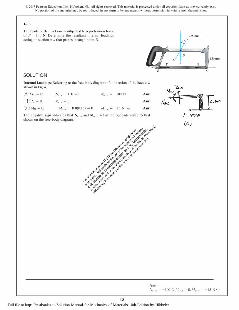
SolutionSolutionInternal Loadings: Referring to the free-body diagram of the section of the hacksaw shown in Fig. a,
d + ΣFx = 0; Na - a + 100 = 0 Na - a = -100 N Ans.
+ c ΣFy = 0; Va - a = 0 Ans.
a+ ΣMD = 0; - Ma - a - 100(0.15) = 0 Ma - a = -15 N # m Ans.
The negative sign indicates that Na - a and Ma - a act in the opposite sense to that shown on the free-body diagram.
1–13.
The blade of the hacksaw is subjected to a pretension force of F = 100 N. Determine the resultant internal loadings acting on section a–a that passes through point D.
A B
C
D
F F
a
b
ba
30�
225 mm
150 mm
E
Ans: Na - a = -100 N, Va - a = 0, Ma - a = -15 N # m
This w
ork is
prote
cted b
y Unit
ed S
tates
copy
right
laws
and i
s prov
ided s
olely
for th
e use
of in
struc
tors i
n tea
ching
their c
ourse
s and
asse
ssing
stud
ent le
arning
. Diss
emina
tion
or sa
le of
any p
art of
this
work (in
cludin
g on t
he W
orld W
ide W
eb)
will de
stroy
the i
ntegri
ty of
the w
ork an
d is n
ot pe
rmitte
d.
Full file at https://testbanku.eu/Solution-Manual-for-Mechanics-of-Materials-10th-Edition-by-Hibbeler

14
© 2017 Pearson Education, Inc., Hoboken, NJ. All rights reserved. This material is protected under all copyright laws as they currently exist. No portion of this material may be reproduced, in any form or by any means, without permission in writing from the publisher.
SolutionSolutionInternal Loadings: Referring to the free-body diagram of the section of the hacksaw shown in Fig. a,
ΣFx′ = 0; Nb - b + 100 cos 30° = 0 Nb - b = -86.6 N Ans.
ΣFy′ = 0; Vb - b - 100 sin 30° = 0 Vb - b = 50 N Ans.
a+ ΣMD = 0; -Mb - b - 100(0.15) = 0 Mb - b = -15 N # m Ans.
The negative sign indicates that Nb–b and Mb–b act in the opposite sense to that shown on the free-body diagram.
1–14.
The blade of the hacksaw is subjected to a pretension force of F = 100 N. Determine the resultant internal loadings acting on section b–b that passes through point D.
A B
C
D
F F
a
b
ba
30�
225 mm
150 mm
E
Ans: Nb - b = -86.6 N, Vb - b = 50 N, Mb - b = -15 N # m
This w
ork is
prote
cted b
y Unit
ed S
tates
copy
right
laws
and i
s prov
ided s
olely
for th
e use
of in
struc
tors i
n tea
ching
their c
ourse
s and
asse
ssing
stud
ent le
arning
. Diss
emina
tion
or sa
le of
any p
art of
this
work (in
cludin
g on t
he W
orld W
ide W
eb)
will de
stroy
the i
ntegri
ty of
the w
ork an
d is n
ot pe
rmitte
d.
Full file at https://testbanku.eu/Solution-Manual-for-Mechanics-of-Materials-10th-Edition-by-Hibbeler

15
© 2017 Pearson Education, Inc., Hoboken, NJ. All rights reserved. This material is protected under all copyright laws as they currently exist. No portion of this material may be reproduced, in any form or by any means, without permission in writing from the publisher.
Solution
1–15.
The beam supports the triangular distributed load shown. Determine the resultant internal loadings on the cross section at point C. Assume the reactions at the supports A and B are vertical.
6 ft6 ft
CA B
4.5 ft
800 lb/ft
6 ft 4.5 ft
ED
SolutionSupport Reactions: Referring to the FBD of the entire beam, Fig. a,
a+ ΣMB = 0; 12
(0.8)(18)(6) -12
(0.8)(9)(3) - Ay(18) = 0 Ay = 1.80 kip
Internal Loadings: Referring to the FBD of the left beam segment sectioned through point C, Fig. b,
S + ΣFx = 0; NC = 0 Ans.
+ c ΣFy = 0; 1.80 -12
(0.5333)(12) - VC = 0 VC = -1.40 kip Ans.
a+ ΣMC = 0; MC +12
(0.5333)(12)(4) - 1.80(12) = 0
MC = 8.80 kip # ft Ans.
The negative sign indicates that VC acts in the sense opposite to that shown on the FBD.
Ans:NC = 0,VC = -1.40 kip,MC = 8.80 kip # ft
This w
ork is
prote
cted b
y Unit
ed S
tates
copy
right
laws
and i
s prov
ided s
olely
for th
e use
of in
struc
tors i
n tea
ching
their c
ourse
s and
asse
ssing
stud
ent le
arning
. Diss
emina
tion
or sa
le of
any p
art of
this
work (in
cludin
g on t
he W
orld W
ide W
eb)
will de
stroy
the i
ntegri
ty of
the w
ork an
d is n
ot pe
rmitte
d.
Full file at https://testbanku.eu/Solution-Manual-for-Mechanics-of-Materials-10th-Edition-by-Hibbeler

16
© 2017 Pearson Education, Inc., Hoboken, NJ. All rights reserved. This material is protected under all copyright laws as they currently exist. No portion of this material may be reproduced, in any form or by any means, without permission in writing from the publisher.
Solution
*1–16.
The beam supports the distributed load shown. Determine the resultant internal loadings on the cross section at points D and E. Assume the reactions at the supports A and B are vertical.
6 ft6 ft
CA B
4.5 ft
800 lb/ft
6 ft 4.5 ft
ED
SolutionSupport Reactions: Referring to the FBD of the entire beam, Fig. a,
a+ ΣMB = 0; 12
(0.8)(18)(6) -12
(0.8)(9)(3) - Ay(18) = 0 Ay = 1.80 kip
Internal Loadings: Referring to the FBD of the left segment of the beam section through D, Fig. b,
S + ΣFx = 0; ND = 0 Ans.
+ c ΣFy = 0; 1.80 -12
(0.2667)(6) - VD = 0 VD = 1.00 kip Ans.
a+ ΣMD = 0; MD +12
(0.2667)(6)(2) - 1.80(6) = 0
MD = 9.20 kip # ft Ans.
Referring to the FBD of the right segment of the beam sectioned through E, Fig. c,
S + ΣFx = 0; NE = 0 Ans.
+ c ΣFy = 0; VE -12
(0.4)(4.5) = 0 VE = 0.900 kip Ans.
a+ ΣME = 0; -ME -12
(0.4)(4.5)(1.5) = 0 ME = -1.35 kip # ft Ans.
The negative sign indicates that ME act in the sense opposite to that shown in Fig. c.
Ans:ND = 0,VD = 1.00 kip,MD = 9.20 kip # ft,NE = 0,VE = 0.900 kip,ME = -1.35 kip # ft
This w
ork is
prote
cted b
y Unit
ed S
tates
copy
right
laws
and i
s prov
ided s
olely
for th
e use
of in
struc
tors i
n tea
ching
their c
ourse
s and
asse
ssing
stud
ent le
arning
. Diss
emina
tion
or sa
le of
any p
art of
this
work (in
cludin
g on t
he W
orld W
ide W
eb)
will de
stroy
the i
ntegri
ty of
the w
ork an
d is n
ot pe
rmitte
d.
Full file at https://testbanku.eu/Solution-Manual-for-Mechanics-of-Materials-10th-Edition-by-Hibbeler

17
© 2017 Pearson Education, Inc., Hoboken, NJ. All rights reserved. This material is protected under all copyright laws as they currently exist. No portion of this material may be reproduced, in any form or by any means, without permission in writing from the publisher.
SolutionSolutionSupport Reactions:
ΣMz = 0; 160(0.4) + 400(0.7) - Ay (1.4) = 0
Ay = 245.71 N
ΣFy = 0; -245.71 - By + 400 + 160 = 0
By = 314.29 N
ΣMy = 0; 800(1.1) - Az(1.4) = 0 Az = 628.57 N
ΣFz = 0; Bz + 628.57 - 800 = 0 Bz = 171.43 N
Equations of Equilibrium: For point D
ΣFx = 0; (ND)x = 0 Ans.
ΣFy = 0; (VD)y - 314.29 + 160 = 0
(VD)y = 154 N Ans.
ΣFz = 0; 171.43 + (VD)z = 0
(VD)z = -171 N Ans.
ΣMx = 0; (TD)x = 0 Ans.
ΣMy = 0; 171.43(0.55) + (MD)y = 0
(MD)y = -94.3 N # m Ans.
ΣMz = 0; 314.29(0.55) - 160(0.15) + (MD)z = 0
(MD)z = -149 N # m Ans.
1–17.
The shaft is supported at its ends by two bearings A and B and is subjected to the forces applied to the pulleys fixed to the shaft. Determine the resultant internal loadings acting on the cross section at point D. The 400-N forces act in the -z direction and the 200-N and 80-N forces act in the +y direction. The journal bearings at A and B exert only y and z components of force on the shaft.
B
C
200 mm200 mm
300 mm
A
200 N
200 N
400 N400 N
150 mm
400 mm
80 N
80 N
z
x
y
150 mm
D
Ans:
(ND)x = 0,(VD)y = 154 N,(VD)z = -171 N,(TD)x = 0,(MD)y = -94.3 N # m,(MD)z = -149 N # m
This w
ork is
prote
cted b
y Unit
ed S
tates
copy
right
laws
and i
s prov
ided s
olely
for th
e use
of in
struc
tors i
n tea
ching
their c
ourse
s and
asse
ssing
stud
ent le
arning
. Diss
emina
tion
or sa
le of
any p
art of
this
work (in
cludin
g on t
he W
orld W
ide W
eb)
will de
stroy
the i
ntegri
ty of
the w
ork an
d is n
ot pe
rmitte
d.
Full file at https://testbanku.eu/Solution-Manual-for-Mechanics-of-Materials-10th-Edition-by-Hibbeler
18
© 2017 Pearson Education, Inc., Hoboken, NJ. All rights reserved. This material is protected under all copyright laws as they currently exist. No portion of this material may be reproduced, in any form or by any means, without permission in writing from the publisher.
SolutionSolutionSupport Reactions:
ΣMz = 0; 160(0.4) + 400(0.7) - Ay(1.4) = 0
Ay = 245.71 N
ΣFy = 0; -245.71 - By + 400 + 160 = 0
By = 314.29 N
ΣMy = 0; 800(1.1) - Az(1.4) = 0 Az = 628.57 N
ΣFz = 0; Bz + 628.57 - 800 = 0 Bz = 171.43 N
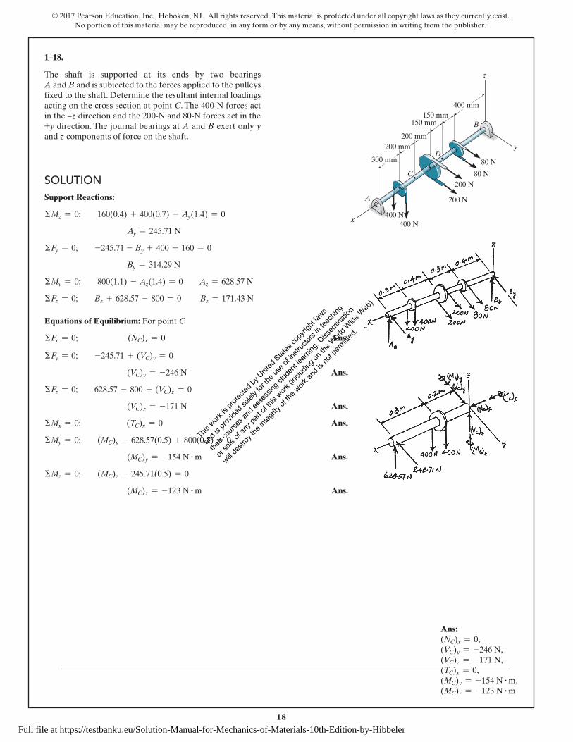
Equations of Equilibrium: For point C
ΣFx = 0; (NC)x = 0 Ans.
ΣFy = 0; -245.71 + (VC)y = 0
(VC)y = -246 N Ans.
ΣFz = 0; 628.57 - 800 + (VC)z = 0
(VC)z = -171 N Ans.
ΣMx = 0; (TC)x = 0 Ans.
ΣMy = 0; (MC)y - 628.57(0.5) + 800(0.2) = 0
(MC)y = -154 N # m Ans.
ΣMz = 0; (MC)z - 245.71(0.5) = 0
(MC)z = -123 N # m Ans.
1–18.
The shaft is supported at its ends by two bearings A and B and is subjected to the forces applied to the pulleys fixed to the shaft. Determine the resultant internal loadings acting on the cross section at point C. The 400-N forces act in the –z direction and the 200-N and 80-N forces act in the +y direction. The journal bearings at A and B exert only y and z components of force on the shaft.
B
C
200 mm200 mm
300 mm
A
200 N
200 N
400 N400 N
150 mm
400 mm
80 N
80 N
z
x
y
150 mm
D
Ans: (NC)x = 0,(VC)y = -246 N,(VC)z = -171 N,(TC)x = 0,(MC)y = -154 N # m,(MC)z = -123 N # m
This w
ork is
prote
cted b
y Unit
ed S
tates
copy
right
laws
and i
s prov
ided s
olely
for th
e use
of in
struc
tors i
n tea
ching
their c
ourse
s and
asse
ssing
stud
ent le
arning
. Diss
emina
tion
or sa
le of
any p
art of
this
work (in
cludin
g on t
he W
orld W
ide W
eb)
will de
stroy
the i
ntegri
ty of
the w
ork an
d is n
ot pe
rmitte
d.
Full file at https://testbanku.eu/Solution-Manual-for-Mechanics-of-Materials-10th-Edition-by-Hibbeler

19
© 2017 Pearson Education, Inc., Hoboken, NJ. All rights reserved. This material is protected under all copyright laws as they currently exist. No portion of this material may be reproduced, in any form or by any means, without permission in writing from the publisher.
SolutionSolutionΣFx = 0; (VA)x = 0 Ans.
ΣFy = 0; (NA)y + 50 sin 30° = 0; (NA)y = -25 lb Ans.
ΣFz = 0; (VA)z - 50 cos 30° = 0; (VA)z = 43.3 lb Ans.
ΣMx = 0; (MA)x - 50 cos 30°(7) = 0; (MA)x = 303 lb # in. Ans.
ΣMy = 0; (TA)y + 50 cos 30°(3) = 0; (TA)y = -130 lb # in. Ans.
ΣMz = 0; (MA)z + 50 sin 30°(3) = 0; (MA)z = -75 lb # in. Ans.
1–19.
The hand crank that is used in a press has the dimensions shown. Determine the resultant internal loadings acting on the cross section at point A if a vertical force of 50 lb is applied to the handle as shown. Assume the crank is fixed to the shaft at B.
B
30�
z
x
y
50 lb
3 in.
7 in.
7 in.
A
Ans:
(VA)x = 0,(NA)y = -25 lb,(VA)z = 43.3 lb,(MA)x = 303 lb # in.,(TA)y = -130 lb # in.,(MA)z = -75 lb # in.
This w
ork is
prote
cted b
y Unit
ed S
tates
copy
right
laws
and i
s prov
ided s
olely
for th
e use
of in
struc
tors i
n tea
ching
their c
ourse
s and
asse
ssing
stud
ent le
arning
. Diss
emina
tion
or sa
le of
any p
art of
this
work (in
cludin
g on t
he W
orld W
ide W
eb)
will de
stroy
the i
ntegri
ty of
the w
ork an
d is n
ot pe
rmitte
d.
Full file at https://testbanku.eu/Solution-Manual-for-Mechanics-of-Materials-10th-Edition-by-Hibbeler

20
© 2017 Pearson Education, Inc., Hoboken, NJ. All rights reserved. This material is protected under all copyright laws as they currently exist. No portion of this material may be reproduced, in any form or by any means, without permission in writing from the publisher.
SolutionSolution+d ΣFx = 0; NC + 2.943 = 0; NC = -2.94 kN Ans.
+ c ΣFy = 0; VC - 2.943 = 0; VC = 2.94 kN Ans.
a+ ΣMC = 0; -MC - 2.943(0.6) + 2.943(0.1) = 0
MC = -1.47 kN # m Ans.
*1–20.
Determine the resultant internal loadings acting on the cross section at point C in the beam. The load D has a mass of 300 kg and is being hoisted by the motor M with constant velocity.
M
2 m
B
CE
D
A
0.1 m
2 m 2 m
1.5 m
0.1 m
1 m
Ans:
NC = -2.94 kN,VC = 2.94 kN,MC = -1.47 kN # m
This w
ork is
prote
cted b
y Unit
ed S
tates
copy
right
laws
and i
s prov
ided s
olely
for th
e use
of in
struc
tors i
n tea
ching
their c
ourse
s and
asse
ssing
stud
ent le
arning
. Diss
emina
tion
or sa
le of
any p
art of
this
work (in
cludin
g on t
he W
orld W
ide W
eb)
will de
stroy
the i
ntegri
ty of
the w
ork an
d is n
ot pe
rmitte
d.
Full file at https://testbanku.eu/Solution-Manual-for-Mechanics-of-Materials-10th-Edition-by-Hibbeler

21
© 2017 Pearson Education, Inc., Hoboken, NJ. All rights reserved. This material is protected under all copyright laws as they currently exist. No portion of this material may be reproduced, in any form or by any means, without permission in writing from the publisher.
SolutionSolution+S ΣFx = 0; NE + 2943 = 0
NE = -2.94 kN Ans.+T
ΣFy = 0; -2943 - VE = 0
VE = -2.94 kN Ans.
a+ ΣME = 0; ME + 2943(1) = 0
ME = -2.94 kN # m Ans.
1–21.
Determine the resultant internal loadings acting on the cross section at point E. The load D has a mass of 300 kg and is being hoisted by the motor M with constant velocity.
M
2 m
B
CE
D
A
0.1 m
2 m 2 m
1.5 m
0.1 m
1 m
Ans:
NE = -2.94 kN,VE = -2.94 kN,ME = -2.94 kN # m
This w
ork is
prote
cted b
y Unit
ed S
tates
copy
right
laws
and i
s prov
ided s
olely
for th
e use
of in
struc
tors i
n tea
ching
their c
ourse
s and
asse
ssing
stud
ent le
arning
. Diss
emina
tion
or sa
le of
any p
art of
this
work (in
cludin
g on t
he W
orld W
ide W
eb)
will de
stroy
the i
ntegri
ty of
the w
ork an
d is n
ot pe
rmitte
d.
Full file at https://testbanku.eu/Solution-Manual-for-Mechanics-of-Materials-10th-Edition-by-Hibbeler

22
© 2017 Pearson Education, Inc., Hoboken, NJ. All rights reserved. This material is protected under all copyright laws as they currently exist. No portion of this material may be reproduced, in any form or by any means, without permission in writing from the publisher.
SolutionSolutionMember:
a+ΣMA = 0; FBC cos 30°(50) - 120(500) = 0
FBC = 1385.6 N = 1.39 kN Ans.
+ c ΣFy = 0; Ay - 1385.6 - 120 cos 30° = 0
Ay = 1489.56 N
+d ΣFx = 0; Ax - 120 sin 30° = 0; Ax = 60 N
FA = 21489.562 + 602
= 1491 N = 1.49 kN Ans.
Segment:
a+ ΣFx′ = 0; ND - 120 = 0
ND = 120 N Ans.
+Q ΣFy′ = 0; VD = 0 Ans.
a+ΣMD = 0; MD - 120(0.3) = 0
MD = 36.0 N # m Ans.
1–22.
The metal stud punch is subjected to a force of 120 N on the handle. Determine the magnitude of the reactive force at the pin A and in the short link BC. Also, determine the resultant internal loadings acting on the cross section at point D.
Ans: FBC = 1.39 kN, FA = 1.49 kN, ND = 120 N, VD = 0, MD = 36.0 N # m
60� 50 mm
100 mm
200 mm
300 mmB
C
D
120 N
50 mm 100 mm
E
30�
A
This w
ork is
prote
cted b
y Unit
ed S
tates
copy
right
laws
and i
s prov
ided s
olely
for th
e use
of in
struc
tors i
n tea
ching
their c
ourse
s and
asse
ssing
stud
ent le
arning
. Diss
emina
tion
or sa
le of
any p
art of
this
work (in
cludin
g on t
he W
orld W
ide W
eb)
will de
stroy
the i
ntegri
ty of
the w
ork an
d is n
ot pe
rmitte
d.
Full file at https://testbanku.eu/Solution-Manual-for-Mechanics-of-Materials-10th-Edition-by-Hibbeler

23
© 2017 Pearson Education, Inc., Hoboken, NJ. All rights reserved. This material is protected under all copyright laws as they currently exist. No portion of this material may be reproduced, in any form or by any means, without permission in writing from the publisher.
SolutionSolutionMember:
a+ ΣMA = 0; FBC cos 30°(50) - 120(500) = 0
FBC = 1385.6 N = 1.3856 kN
Segment:
+bΣFx′ = 0; NE = 0 Ans.
a + ΣFy′ = 0; VE - 120 = 0; VE = 120 N Ans.
a+ ΣME = 0; ME - 120(0.4) = 0; ME = 48.0 N # m Ans.
Short link:
+d ΣFx = 0; V = 0 Ans.
+ c ΣFy = 0; 1.3856 - N = 0; N = 1.39 kN Ans.
a+ ΣMH = 0; M = 0 Ans.
1–23.
Determine the resultant internal loadings acting on the cross section at point E of the handle arm, and on the cross section of the short link BC.
Ans: NE = 0, VE = 120 N, ME = 48.0 N # m, Short link: V = 0, N = 1.39 kN, M = 0
60� 50 mm
100 mm
200 mm
300 mmB
C
D
120 N
50 mm 100 mm
E
30�
A
This w
ork is
prote
cted b
y Unit
ed S
tates
copy
right
laws
and i
s prov
ided s
olely
for th
e use
of in
struc
tors i
n tea
ching
their c
ourse
s and
asse
ssing
stud
ent le
arning
. Diss
emina
tion
or sa
le of
any p
art of
this
work (in
cludin
g on t
he W
orld W
ide W
eb)
will de
stroy
the i
ntegri
ty of
the w
ork an
d is n
ot pe
rmitte
d.
Full file at https://testbanku.eu/Solution-Manual-for-Mechanics-of-Materials-10th-Edition-by-Hibbeler

24
© 2017 Pearson Education, Inc., Hoboken, NJ. All rights reserved. This material is protected under all copyright laws as they currently exist. No portion of this material may be reproduced, in any form or by any means, without permission in writing from the publisher.
SolutionSolutionFrom FBD (a)
a+ ΣMA = 0; TB(6) - 52(3) = 0; TB = 26 kip
From FBD (b)
a+ ΣMD = 0; TE sin 30°(6) - 26(6) = 0; TE = 52 kip
From FBD (c)
S + ΣFx = 0; -NC - 52 cos 30° = 0; NC = -45.0 kip Ans.
+ c ΣFy = 0; VC + 52 sin 30° - 26 = 0; VC = 0 Ans.
a+ ΣMC = 0; 52 cos 30°(0.2) + 52 sin 30°(3) - 26(3) - MC = 0 MC = 9.00 kip # ft Ans.
*1–24.
Determine the resultant internal loadings acting on the cross section at point C. The cooling unit has a total weight of 52 kip and a center of gravity at G.
3 ft
F
3 ft
30� 30�
0.2 ft
G
A B
ED
C
Ans: NC = -45.0 kip,VC = 0,MC = 9.00 kip # ft
This w
ork is
prote
cted b
y Unit
ed S
tates
copy
right
laws
and i
s prov
ided s
olely
for th
e use
of in
struc
tors i
n tea
ching
their c
ourse
s and
asse
ssing
stud
ent le
arning
. Diss
emina
tion
or sa
le of
any p
art of
this
work (in
cludin
g on t
he W
orld W
ide W
eb)
will de
stroy
the i
ntegri
ty of
the w
ork an
d is n
ot pe
rmitte
d.
Full file at https://testbanku.eu/Solution-Manual-for-Mechanics-of-Materials-10th-Edition-by-Hibbeler
25
© 2017 Pearson Education, Inc., Hoboken, NJ. All rights reserved. This material is protected under all copyright laws as they currently exist. No portion of this material may be reproduced, in any form or by any means, without permission in writing from the publisher.
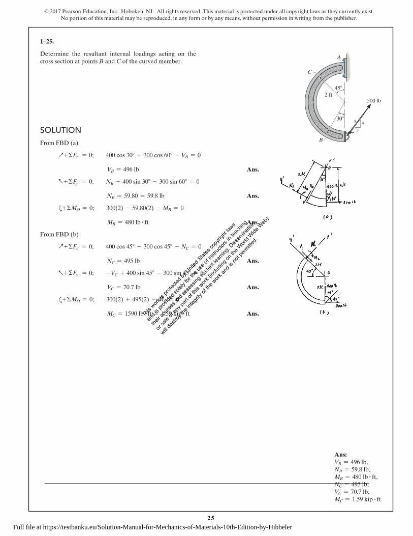
SolutionSolutionFrom FBD (a)
Q + ΣFx′ = 0; 400 cos 30° + 300 cos 60° - VB = 0
VB = 496 lb Ans.
a + ΣFy′ = 0; NB + 400 sin 30° - 300 sin 60° = 0
NB = 59.80 = 59.8 lb Ans.
a+ ΣMO = 0; 300(2) - 59.80(2) - MB = 0
MB = 480 lb # ft Ans.
From FBD (b)
Q + ΣFx′ = 0; 400 cos 45° + 300 cos 45° - NC = 0
NC = 495 lb Ans.
a + ΣFy′ = 0; -VC + 400 sin 45° - 300 sin 45° = 0
VC = 70.7 lb Ans.
a+ ΣMO = 0; 300(2) + 495(2) - MC = 0
MC = 1590 lb # ft = 1.59 kip # ft Ans.
1–25.
Determine the resultant internal loadings acting on the cross section at points B and C of the curved member.
C
A
B
30�
45�
2 ft500 lb
3
45
Ans: VB = 496 lb,NB = 59.8 lb,MB = 480 lb # ft,NC = 495 lb,VC = 70.7 lb,MC = 1.59 kip # ft
This w
ork is
prote
cted b
y Unit
ed S
tates
copy
right
laws
and i
s prov
ided s
olely
for th
e use
of in
struc
tors i
n tea
ching
their c
ourse
s and
asse
ssing
stud
ent le
arning
. Diss
emina
tion
or sa
le of
any p
art of
this
work (in
cludin
g on t
he W
orld W
ide W
eb)
will de
stroy
the i
ntegri
ty of
the w
ork an
d is n
ot pe
rmitte
d.
Full file at https://testbanku.eu/Solution-Manual-for-Mechanics-of-Materials-10th-Edition-by-Hibbeler