soleman midi foot controller - source audio website · soleman midi foot controller user’s guide...
TRANSCRIPT
SA165 Soleman User’s Guide 1
Soleman MIDI Foot Controller
User’s Guide
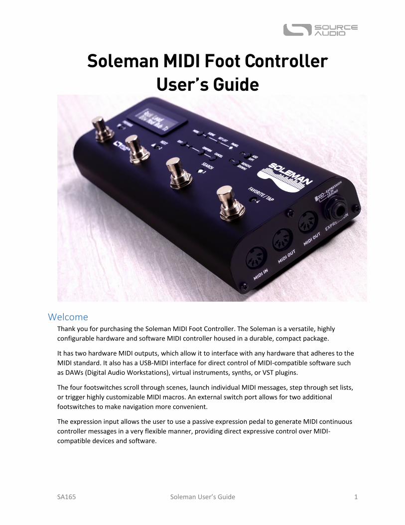
Welcome Thank you for purchasing the Soleman MIDI Foot Controller. The Soleman is a versatile, highly
configurable hardware and software MIDI controller housed in a durable, compact package.
It has two hardware MIDI outputs, which allow it to interface with any hardware that adheres to the
MIDI standard. It also has a USB-MIDI interface for direct control of MIDI-compatible software such
as DAWs (Digital Audio Workstations), virtual instruments, synths, or VST plugins.
The four footswitches scroll through scenes, launch individual MIDI messages, step through set lists,
or trigger highly customizable MIDI macros. An external switch port allows for two additional
footswitches to make navigation more convenient.
The expression input allows the user to use a passive expression pedal to generate MIDI continuous
controller messages in a very flexible manner, providing direct expressive control over MIDI-
compatible devices and software.
SA165 Soleman User’s Guide 2
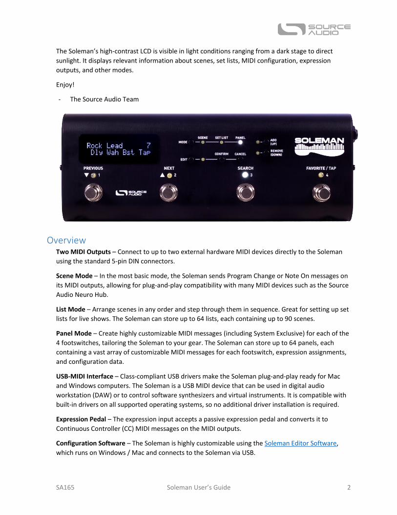
The Soleman’s high-contrast LCD is visible in light conditions ranging from a dark stage to direct
sunlight. It displays relevant information about scenes, set lists, MIDI configuration, expression
outputs, and other modes.
Enjoy!
- The Source Audio Team
Overview Two MIDI Outputs – Connect to up to two external hardware MIDI devices directly to the Soleman
using the standard 5-pin DIN connectors.
Scene Mode – In the most basic mode, the Soleman sends Program Change or Note On messages on
its MIDI outputs, allowing for plug-and-play compatibility with many MIDI devices such as the Source
Audio Neuro Hub.
List Mode – Arrange scenes in any order and step through them in sequence. Great for setting up set
lists for live shows. The Soleman can store up to 64 lists, each containing up to 90 scenes.
Panel Mode – Create highly customizable MIDI messages (including System Exclusive) for each of the
4 footswitches, tailoring the Soleman to your gear. The Soleman can store up to 64 panels, each
containing a vast array of customizable MIDI messages for each footswitch, expression assignments,
and configuration data.
USB-MIDI Interface – Class-compliant USB drivers make the Soleman plug-and-play ready for Mac
and Windows computers. The Soleman is a USB MIDI device that can be used in digital audio
workstation (DAW) or to control software synthesizers and virtual instruments. It is compatible with
built-in drivers on all supported operating systems, so no additional driver installation is required.
Expression Pedal – The expression input accepts a passive expression pedal and converts it to
Continuous Controller (CC) MIDI messages on the MIDI outputs.
Configuration Software – The Soleman is highly customizable using the Soleman Editor Software,
which runs on Windows / Mac and connects to the Soleman via USB.
SA165 Soleman User’s Guide 3
Contents Welcome .................................................................................................................................................. 1
Overview .................................................................................................................................................. 2
Quick Start ............................................................................................................................................... 3
User Interface Overview .......................................................................................................................... 5
Footswitch Overview ............................................................................................................................... 5
Connections ............................................................................................................................................. 6
Scene Mode ............................................................................................................................................. 8
List Mode ............................................................................................................................................... 11
Panel Mode ............................................................................................................................................ 14
Macros ................................................................................................................................................... 18
Expression Pedal .................................................................................................................................... 18
USB MIDI Interface ................................................................................................................................ 19
Edit Menu .............................................................................................................................................. 19
Global Edit Menu ................................................................................................................................... 22
External Footswitches ............................................................................................................................ 27
USB Editor Software .............................................................................................................................. 28
Appendix ................................................................................................................................................ 36
Specifications ......................................................................................................................................... 37
Waste Disposal Notes ............................................................................................................................ 37
Warranty ................................................................................................................................................ 38
Version History ...................................................................................................................................... 39
Quick Start This section will guide you through the process of powering the Soleman and using it in a simple MIDI
setup with program change (PC) messages. For this example, the Neuro Hub will be used as the
target device. The Soleman will send program change messages to the Neuro Hub in order to change
scenes, which are stored in the Hub’s internal memory.
If you wish to skip the Quick Start, you can skip ahead to more detailed descriptions of the Soleman’s
operation, starting with the User Interface Overview.
Power The Soleman ships with an included 9V DC power supply. Plug the adapter into a wall outlet and
connect the barrel plug to the Soleman’s power jack (labeled 9V DC).
SA165 Soleman User’s Guide 4
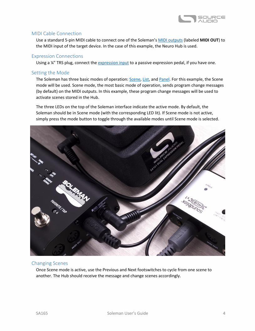
MIDI Cable Connection Use a standard 5-pin MIDI cable to connect one of the Soleman’s MIDI outputs (labeled MIDI OUT) to
the MIDI input of the target device. In the case of this example, the Neuro Hub is used.
Expression Connections Using a ¼” TRS plug, connect the expression input to a passive expression pedal, if you have one.
Setting the Mode The Soleman has three basic modes of operation: Scene, List, and Panel. For this example, the Scene
mode will be used. Scene mode, the most basic mode of operation, sends program change messages
(by default) on the MIDI outputs. In this example, these program change messages will be used to
activate scenes stored in the Hub.
The three LEDs on the top of the Soleman interface indicate the active mode. By default, the
Soleman should be in Scene mode (with the corresponding LED lit). If Scene mode is not active,
simply press the mode button to toggle through the available modes until Scene mode is selected.
Changing Scenes Once Scene mode is active, use the Previous and Next footswitches to cycle from one scene to
another. The Hub should receive the message and change scenes accordingly.
SA165 Soleman User’s Guide 5
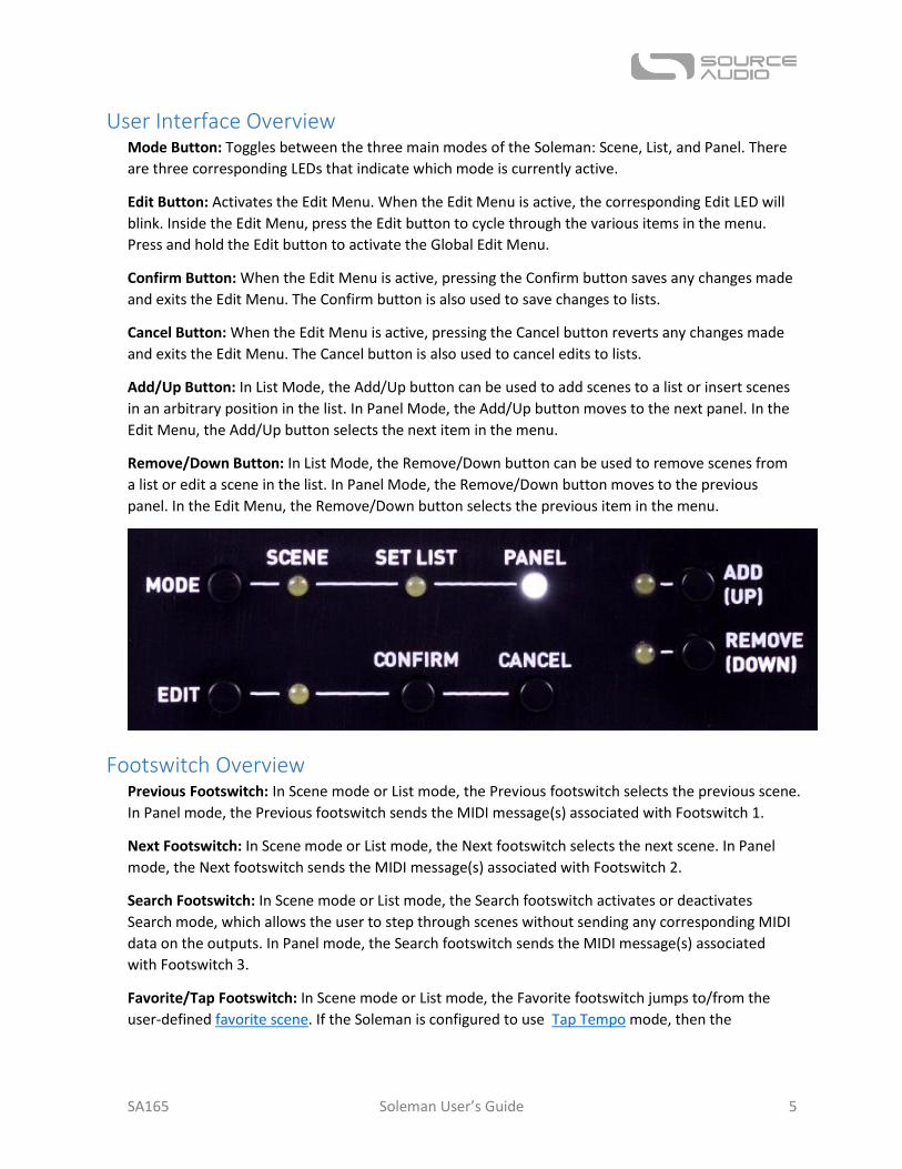
User Interface Overview Mode Button: Toggles between the three main modes of the Soleman: Scene, List, and Panel. There
are three corresponding LEDs that indicate which mode is currently active.
Edit Button: Activates the Edit Menu. When the Edit Menu is active, the corresponding Edit LED will
blink. Inside the Edit Menu, press the Edit button to cycle through the various items in the menu.
Press and hold the Edit button to activate the Global Edit Menu.
Confirm Button: When the Edit Menu is active, pressing the Confirm button saves any changes made
and exits the Edit Menu. The Confirm button is also used to save changes to lists.
Cancel Button: When the Edit Menu is active, pressing the Cancel button reverts any changes made
and exits the Edit Menu. The Cancel button is also used to cancel edits to lists.
Add/Up Button: In List Mode, the Add/Up button can be used to add scenes to a list or insert scenes
in an arbitrary position in the list. In Panel Mode, the Add/Up button moves to the next panel. In the
Edit Menu, the Add/Up button selects the next item in the menu.
Remove/Down Button: In List Mode, the Remove/Down button can be used to remove scenes from
a list or edit a scene in the list. In Panel Mode, the Remove/Down button moves to the previous
panel. In the Edit Menu, the Remove/Down button selects the previous item in the menu.
Footswitch Overview Previous Footswitch: In Scene mode or List mode, the Previous footswitch selects the previous scene.
In Panel mode, the Previous footswitch sends the MIDI message(s) associated with Footswitch 1.
Next Footswitch: In Scene mode or List mode, the Next footswitch selects the next scene. In Panel
mode, the Next footswitch sends the MIDI message(s) associated with Footswitch 2.
Search Footswitch: In Scene mode or List mode, the Search footswitch activates or deactivates
Search mode, which allows the user to step through scenes without sending any corresponding MIDI
data on the outputs. In Panel mode, the Search footswitch sends the MIDI message(s) associated
with Footswitch 3.
Favorite/Tap Footswitch: In Scene mode or List mode, the Favorite footswitch jumps to/from the
user-defined favorite scene. If the Soleman is configured to use Tap Tempo mode, then the
SA165 Soleman User’s Guide 6
Favorite/Tap footswitch is instead used to set the tempo for the MIDI clock output. In Panel mode,
the Favorite/Tap footswitch sends the MIDI message(s) associated with Footswitch 4.
Connections
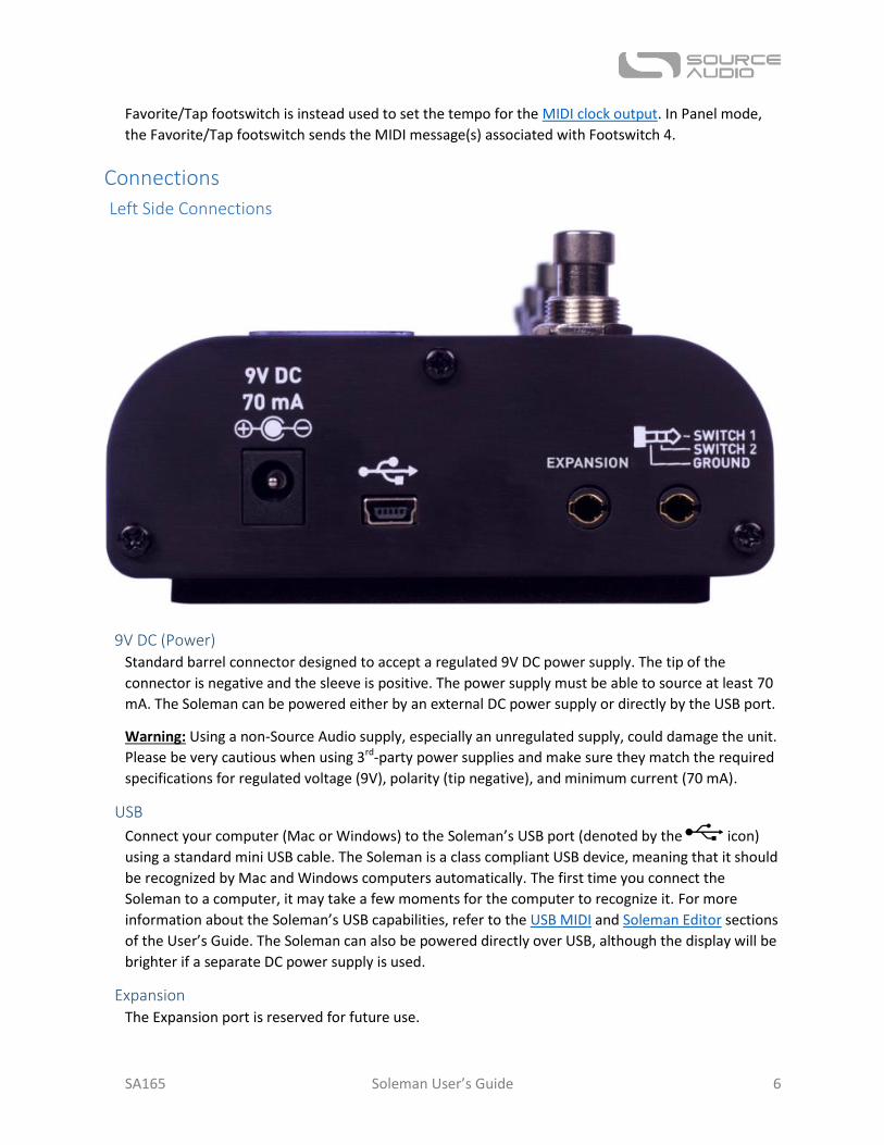
Left Side Connections
9V DC (Power) Standard barrel connector designed to accept a regulated 9V DC power supply. The tip of the
connector is negative and the sleeve is positive. The power supply must be able to source at least 70
mA. The Soleman can be powered either by an external DC power supply or directly by the USB port.
Warning: Using a non-Source Audio supply, especially an unregulated supply, could damage the unit.
Please be very cautious when using 3rd-party power supplies and make sure they match the required
specifications for regulated voltage (9V), polarity (tip negative), and minimum current (70 mA).
USB
Connect your computer (Mac or Windows) to the Soleman’s USB port (denoted by the icon)
using a standard mini USB cable. The Soleman is a class compliant USB device, meaning that it should
be recognized by Mac and Windows computers automatically. The first time you connect the
Soleman to a computer, it may take a few moments for the computer to recognize it. For more
information about the Soleman’s USB capabilities, refer to the USB MIDI and Soleman Editor sections
of the User’s Guide. The Soleman can also be powered directly over USB, although the display will be
brighter if a separate DC power supply is used.
Expansion The Expansion port is reserved for future use.
SA165 Soleman User’s Guide 7
External Switch Port Up to two external switches can be connected to this port for additional ease of navigation in List and
Panel modes. The specific function of each switch can be set using in the Global Hardware Options
using the Edit Menu or the Soleman Editor software. For more information, refer to the External
Footswitches section.
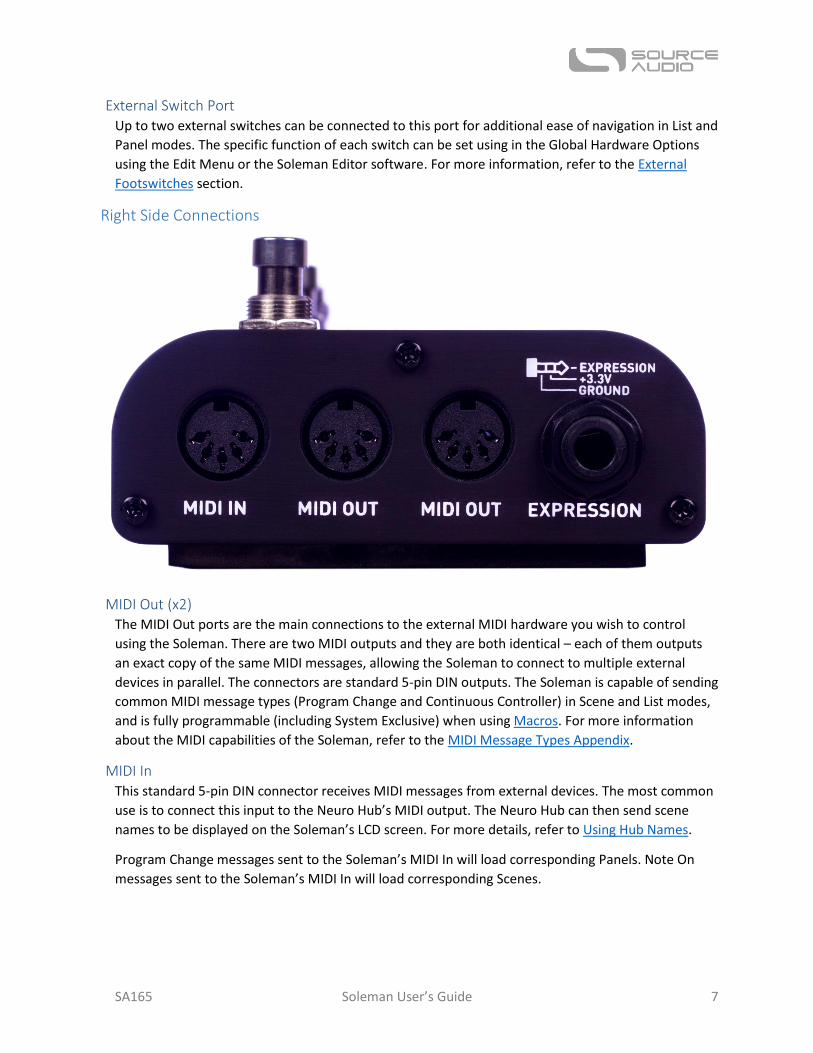
Right Side Connections
MIDI Out (x2) The MIDI Out ports are the main connections to the external MIDI hardware you wish to control
using the Soleman. There are two MIDI outputs and they are both identical – each of them outputs
an exact copy of the same MIDI messages, allowing the Soleman to connect to multiple external
devices in parallel. The connectors are standard 5-pin DIN outputs. The Soleman is capable of sending
common MIDI message types (Program Change and Continuous Controller) in Scene and List modes,
and is fully programmable (including System Exclusive) when using Macros. For more information
about the MIDI capabilities of the Soleman, refer to the MIDI Message Types Appendix.
MIDI In This standard 5-pin DIN connector receives MIDI messages from external devices. The most common
use is to connect this input to the Neuro Hub’s MIDI output. The Neuro Hub can then send scene
names to be displayed on the Soleman’s LCD screen. For more details, refer to Using Hub Names.
Program Change messages sent to the Soleman’s MIDI In will load corresponding Panels. Note On
messages sent to the Soleman’s MIDI In will load corresponding Scenes.
SA165 Soleman User’s Guide 8
Expression Input The expression input connects to an external passive expression pedal. The plug is TRS and “tip hot.”
The expression signal is on the tip, power (3.3 V) is on the ring, and the sleeve is ground. The
Soleman has an Expression Calibration function which makes it compatible with expression pedals
that have a wide range of different resistances.
Scene Mode In Scene Mode, the Soleman steps through programs in sequential order and outputs Program
Change messages, Note On messages, or Macros. Program Change messages are enabled by default.
This is the simplest mode of operation and matches the functionality of most simple MIDI
footswitches.
This mode works very well with Source Audio’s Neuro Hub, as a way to recall Scenes. Scenes are
basically a way of storing preset information for multiple effects pedals in the same system, with the
benefit of being able to save and recall those presets all at the same time with a single program
change message.
There are a total of 128 Scenes available in the Soleman, and each has a corresponding MIDI message
that is sent from the MIDI outputs (hardware and USB) when the Scene is activated. By default, each
Scene will output a MIDI Program Change message. The number of the Program Change message
corresponds to the Scene number. For example, when Scene 5 is activated, a Program Change
message with a program number of 5 will be sent from the MIDI outputs.
It is also possible to configure the Soleman to send other MIDI message types (such as Note On
messages or macros) in Scene Mode. This can be done using the USB Editor Software.
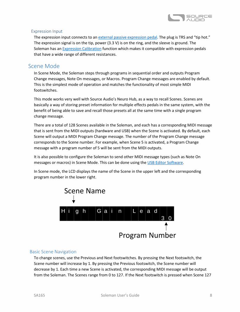
In Scene mode, the LCD displays the name of the Scene in the upper left and the corresponding
program number in the lower right.
Basic Scene Navigation To change scenes, use the Previous and Next footswitches. By pressing the Next footswitch, the
Scene number will increase by 1. By pressing the Previous footswitch, the Scene number will
decrease by 1. Each time a new Scene is activated, the corresponding MIDI message will be output
from the Soleman. The Scenes range from 0 to 127. If the Next footswitch is pressed when Scene 127
H i g h G a i n L e a d
3 0
Scene Name
Program Number
SA165 Soleman User’s Guide 9
is active, then the Soleman will jump to Scene 0. If the Previous footswitch is pressed when Scene 0 is
active, then the Soleman will jump to Scene 127.
External expansion footswitches, if connected, can also be used to change Scenes in the same
manner as the Previous and Next footswitches.
Scene Search Press the Search footswitch to activate Scene Search mode. When Scene Search mode is active, the
Search LED will blink. This indicates that you can select other scenes using the Next and Previous
footswitches without sending out the corresponding MIDI messages. When the desired Scene is
selected, press the Search footswitch again. This will exit Scene Search mode and activate the Scene,
sending the corresponding MIDI message on the MIDI outputs. Note that while Search Mode is active,
all MIDI output (except MIDI clock) will be disabled.
When in Scene Search mode, press and hold either the Next or Previous footswitches to rapidly scroll
through Scenes.
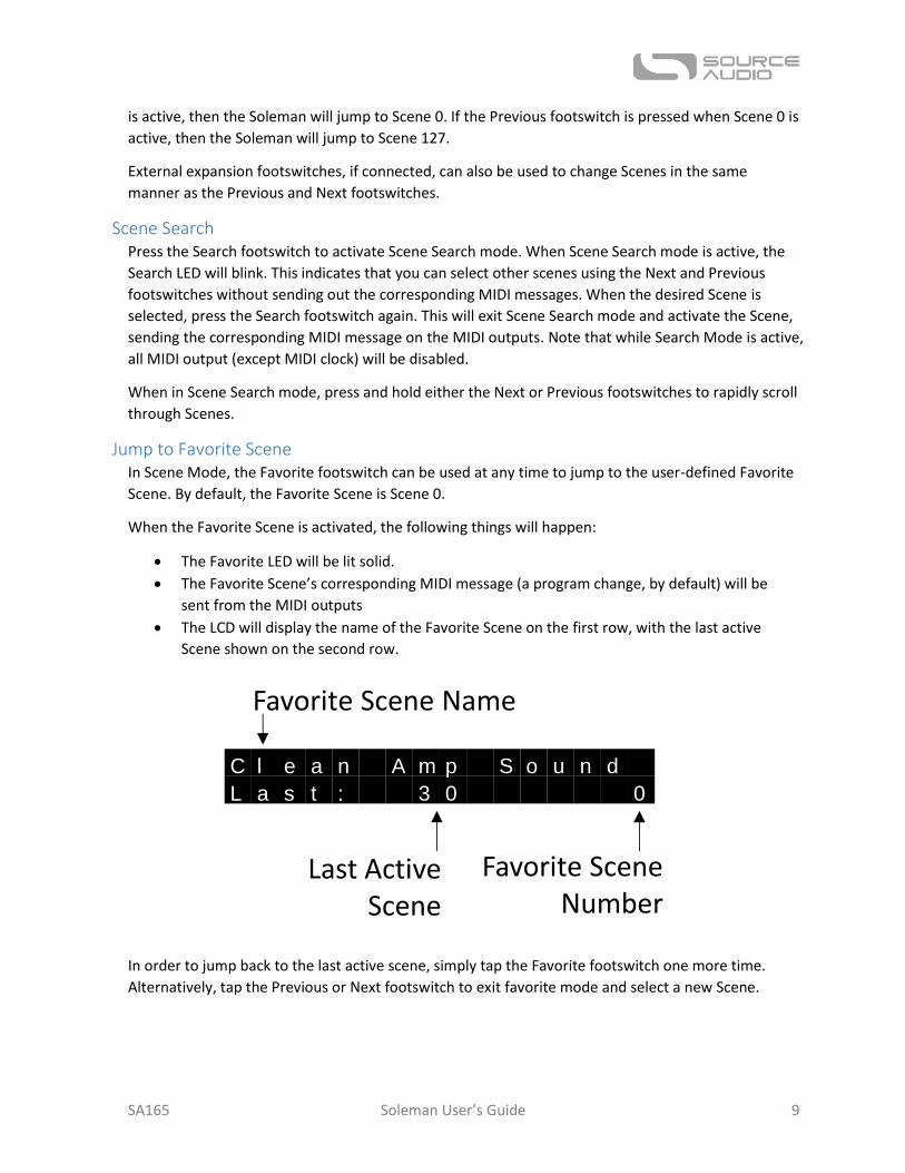
Jump to Favorite Scene In Scene Mode, the Favorite footswitch can be used at any time to jump to the user-defined Favorite
Scene. By default, the Favorite Scene is Scene 0.
When the Favorite Scene is activated, the following things will happen:
The Favorite LED will be lit solid.
The Favorite Scene’s corresponding MIDI message (a program change, by default) will be
sent from the MIDI outputs
The LCD will display the name of the Favorite Scene on the first row, with the last active
Scene shown on the second row.
In order to jump back to the last active scene, simply tap the Favorite footswitch one more time.
Alternatively, tap the Previous or Next footswitch to exit favorite mode and select a new Scene.
C l e a n A m p S o u n d
L a s t : 3 0 0
Favorite Scene Name
Favorite SceneNumber
Last ActiveScene
SA165 Soleman User’s Guide 10
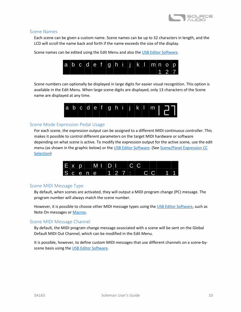
Scene Names Each scene can be given a custom name. Scene names can be up to 32 characters in length, and the
LCD will scroll the name back and forth if the name exceeds the size of the display.
Scene names can be edited using the Edit Menu and also the USB Editor Software.
Scene numbers can optionally be displayed in large digits for easier visual recognition. This option is
available in the Edit Menu. When large scene digits are displayed, only 13 characters of the Scene
name are displayed at any time.
Scene Mode Expression Pedal Usage For each scene, the expression output can be assigned to a different MIDI continuous controller. This
makes it possible to control different parameters on the target MIDI hardware or software
depending on what scene is active. To modify the expression output for the active scene, use the edit
menu (as shown in the graphic below) or the USB Editor Software. (See Scene/Panel Expression CC
Selection)
Scene MIDI Message Type By default, when scenes are activated, they will output a MIDI program change (PC) message. The
program number will always match the scene number.
However, it is possible to choose other MIDI message types using the USB Editor Software, such as
Note On messages or Macros.
Scene MIDI Message Channel By default, the MIDI program change message associated with a scene will be sent on the Global
Default MIDI Out Channel, which can be modified in the Edit Menu.
It is possible, however, to define custom MIDI messages that use different channels on a scene-by-
scene basis using the USB Editor Software.
a b c d e f g h i j k l m n o p
1 2 7
a b c d e f g h i j k l m
E x p M I D I C C
S c e n e 1 2 7 : C C 1 1
SA165 Soleman User’s Guide 11
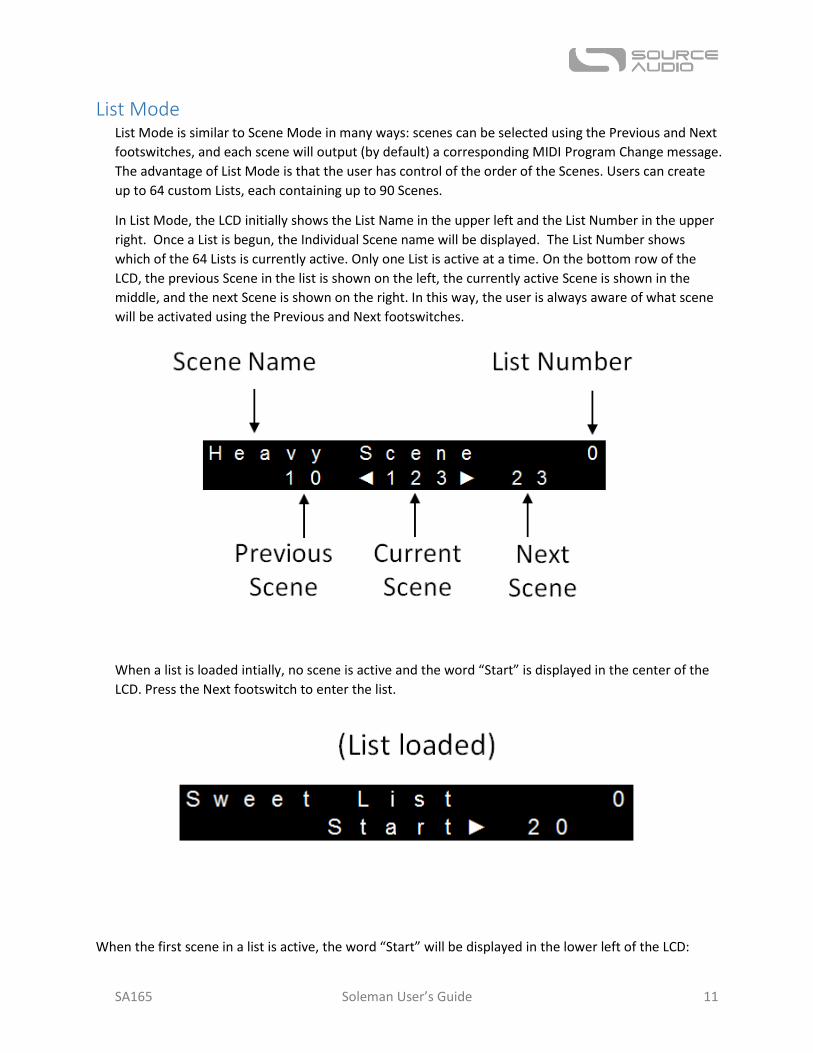
List Mode List Mode is similar to Scene Mode in many ways: scenes can be selected using the Previous and Next
footswitches, and each scene will output (by default) a corresponding MIDI Program Change message.
The advantage of List Mode is that the user has control of the order of the Scenes. Users can create
up to 64 custom Lists, each containing up to 90 Scenes.
In List Mode, the LCD initially shows the List Name in the upper left and the List Number in the upper
right. Once a List is begun, the Individual Scene name will be displayed. The List Number shows
which of the 64 Lists is currently active. Only one List is active at a time. On the bottom row of the
LCD, the previous Scene in the list is shown on the left, the currently active Scene is shown in the
middle, and the next Scene is shown on the right. In this way, the user is always aware of what scene
will be activated using the Previous and Next footswitches.
When a list is loaded intially, no scene is active and the word “Start” is displayed in the center of the
LCD. Press the Next footswitch to enter the list.
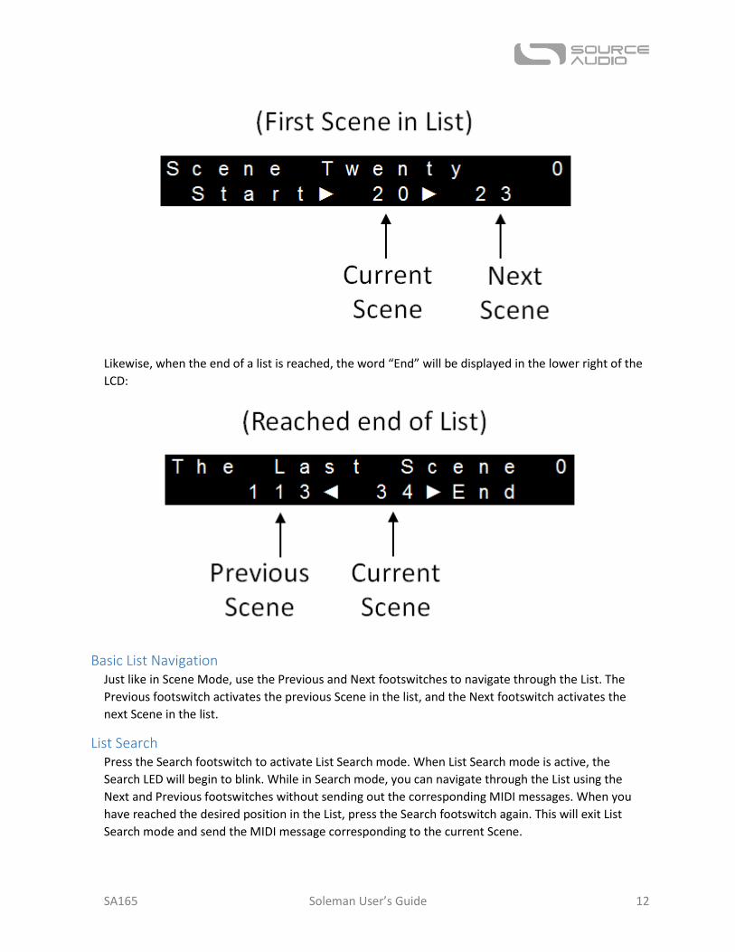
When the first scene in a list is active, the word “Start” will be displayed in the lower left of the LCD:
SA165 Soleman User’s Guide 12
Likewise, when the end of a list is reached, the word “End” will be displayed in the lower right of the
LCD:
Basic List Navigation Just like in Scene Mode, use the Previous and Next footswitches to navigate through the List. The
Previous footswitch activates the previous Scene in the list, and the Next footswitch activates the
next Scene in the list.
List Search Press the Search footswitch to activate List Search mode. When List Search mode is active, the
Search LED will begin to blink. While in Search mode, you can navigate through the List using the
Next and Previous footswitches without sending out the corresponding MIDI messages. When you
have reached the desired position in the List, press the Search footswitch again. This will exit List
Search mode and send the MIDI message corresponding to the current Scene.
SA165 Soleman User’s Guide 13
Press and hold either the Next or Previous footswitches when List Search is active to rapidly scroll
through the List.
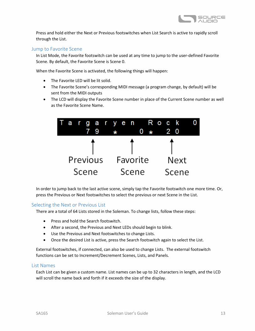
Jump to Favorite Scene In List Mode, the Favorite footswitch can be used at any time to jump to the user-defined Favorite
Scene. By default, the Favorite Scene is Scene 0.
When the Favorite Scene is activated, the following things will happen:
The Favorite LED will be lit solid.
The Favorite Scene’s corresponding MIDI message (a program change, by default) will be
sent from the MIDI outputs
The LCD will display the Favorite Scene number in place of the Current Scene number as well
as the Favorite Scene Name.
In order to jump back to the last active scene, simply tap the Favorite footswitch one more time. Or,
press the Previous or Next footswitches to select the previous or next Scene in the List.
Selecting the Next or Previous List There are a total of 64 Lists stored in the Soleman. To change lists, follow these steps:
Press and hold the Search footswitch.
After a second, the Previous and Next LEDs should begin to blink.
Use the Previous and Next footswitches to change Lists.
Once the desired List is active, press the Search footswitch again to select the List.
External footswitches, if connected, can also be used to change Lists. The external footswitch
functions can be set to Increment/Decrement Scenes, Lists, and Panels.
List Names Each List can be given a custom name. List names can be up to 32 characters in length, and the LCD
will scroll the name back and forth if it exceeds the size of the display.
SA165 Soleman User’s Guide 14
Editing Lists Lists can be modified using the hardware user interface or by using the USB Editor Software. The
following sections describe how to add, insert, remove, or edit a Scene in the List.
Adding a Scene to then end of a List
Press the Add button once.
A scene will be added to the end of the list and the Add LED will begin to blink.
Use the Previous and Next footswitches to change the number of the scene added to the List.
Press the Add button or the Confirm button to accept the changes. Or, press the Cancel
button to cancel the changes and revert the List to its previous state.
Inserting a Scene into a List
Press and hold the Add button for 2 seconds.
A scene will be inserted into the list prior to the current position and the Add LED will begin
to blink.
Use the Previous and Next footswitches to change the number of the scene inserted in the
List.
Press the Add button or the Confirm button to accept the changes. Or, press the Cancel
button to cancel the changes and revert the List to its previous state.
Removing a Scene from a List
Press the Remove button.
The currently selected scene will be removed from the List.
Editing a Scene in a List
Press and hold the Remove button for 2 seconds.
The Remove LED will begin to blink.
Use the Previous and Next footswitches to change the number of the currently selected
scene.
Press the Remove button or the Confirm button to accept the changes. Or, press the Cancel
button to cancel the changes and revert the List to its previous state.
List Mode Expression Pedal When List Mode is active, expression pedals will be mapped to the continuous controller defined by
the currently active Scene. This means that the expression pedal can control many different
parameters on external MIDI hardware that vary on a scene-to-scene basis.
Panel Mode Panel Mode is the most powerful and flexible operating mode of the Soleman. In Panel mode, each
footswitch is capable of sending a completely customizable MIDI message (or group of multiple MIDI
messages) when it is activated as well as a different MIDI message (or group of multiple MIDI
messages) when it is deactivated. This allows the user to create a control surface that is highly
customized for their specific use case.
SA165 Soleman User’s Guide 15
One common use case of panel mode is to use each individual footswitch to turn independent MIDI-
controllable effects on or off.
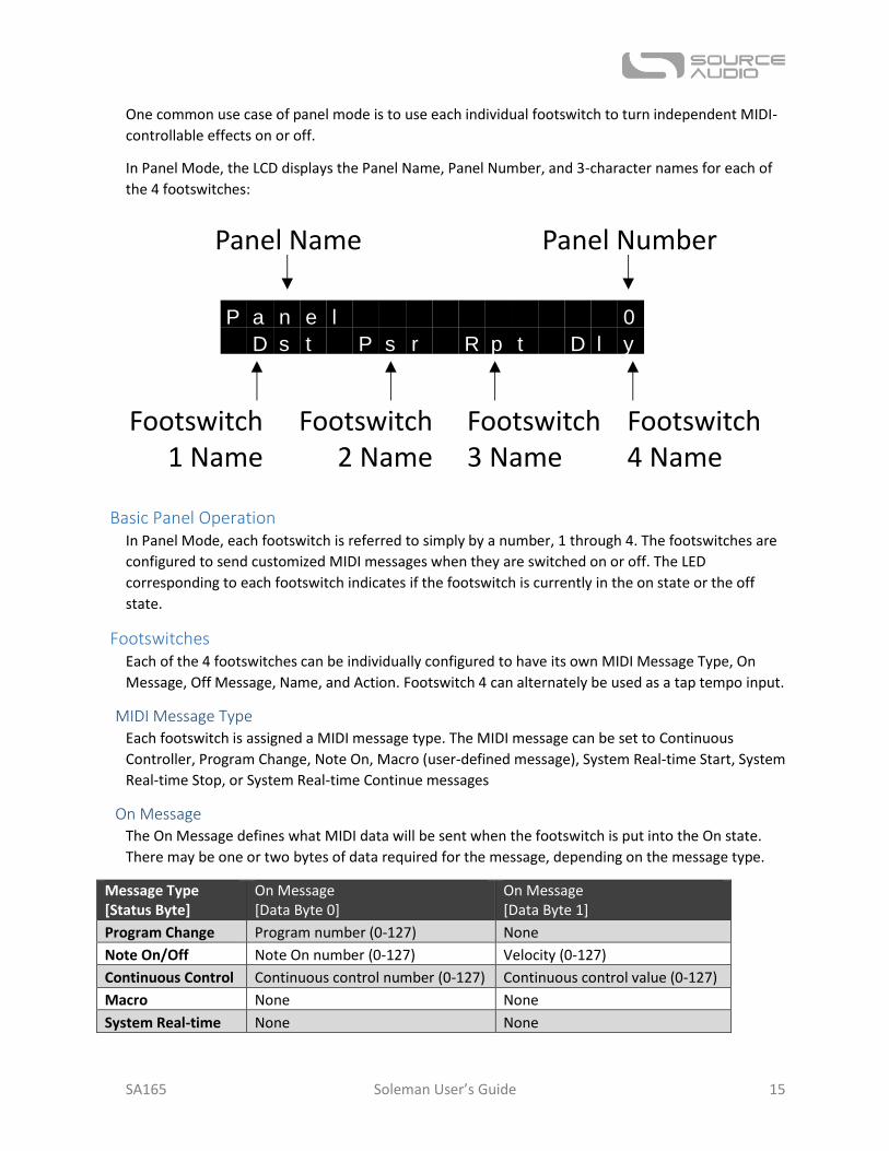
In Panel Mode, the LCD displays the Panel Name, Panel Number, and 3-character names for each of
the 4 footswitches:
Basic Panel Operation In Panel Mode, each footswitch is referred to simply by a number, 1 through 4. The footswitches are
configured to send customized MIDI messages when they are switched on or off. The LED
corresponding to each footswitch indicates if the footswitch is currently in the on state or the off
state.
Footswitches Each of the 4 footswitches can be individually configured to have its own MIDI Message Type, On
Message, Off Message, Name, and Action. Footswitch 4 can alternately be used as a tap tempo input.
MIDI Message Type Each footswitch is assigned a MIDI message type. The MIDI message can be set to Continuous
Controller, Program Change, Note On, Macro (user-defined message), System Real-time Start, System
Real-time Stop, or System Real-time Continue messages
On Message The On Message defines what MIDI data will be sent when the footswitch is put into the On state.
There may be one or two bytes of data required for the message, depending on the message type.
Message Type [Status Byte]
On Message [Data Byte 0]
On Message [Data Byte 1]
Program Change Program number (0-127) None
Note On/Off Note On number (0-127) Velocity (0-127)
Continuous Control Continuous control number (0-127) Continuous control value (0-127)
Macro None None
System Real-time None None
P a n e l 0
D s t P s r R p t D l y
Footswitch1 Name
Footswitch4 Name
Footswitch2 Name
Footswitch3 Name
Panel Name Panel Number
SA165 Soleman User’s Guide 16
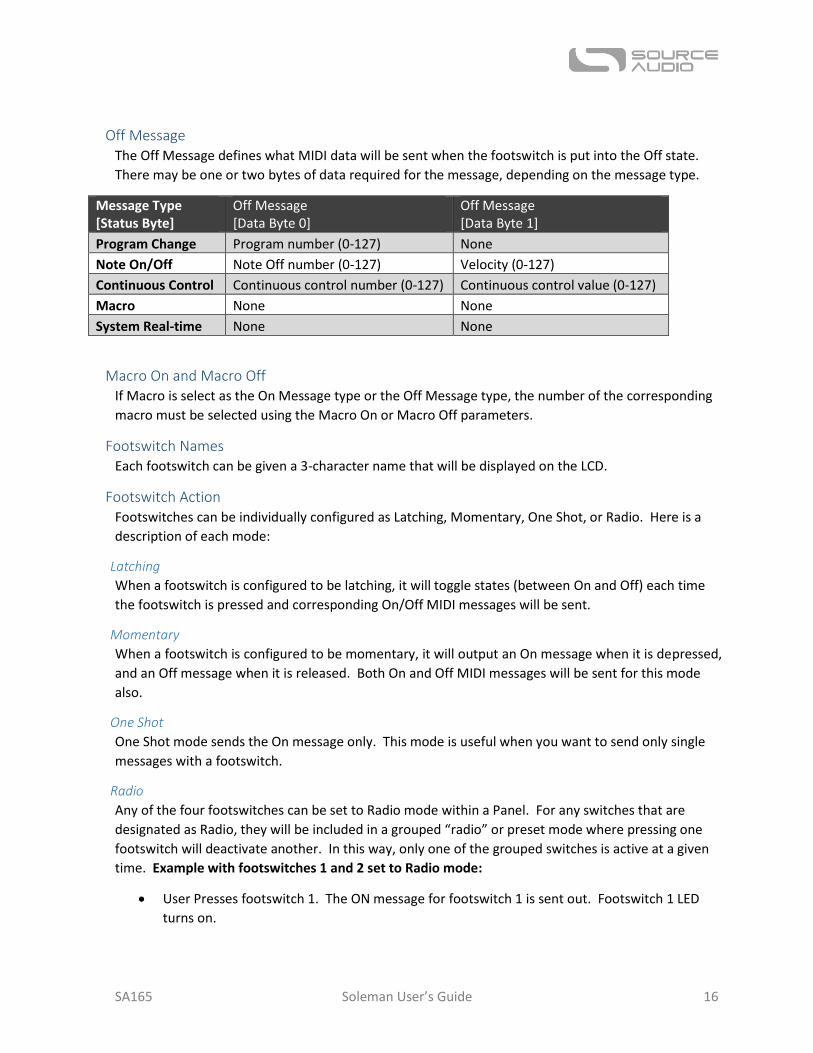
Off Message The Off Message defines what MIDI data will be sent when the footswitch is put into the Off state.
There may be one or two bytes of data required for the message, depending on the message type.
Message Type [Status Byte]
Off Message [Data Byte 0]
Off Message [Data Byte 1]
Program Change Program number (0-127) None
Note On/Off Note Off number (0-127) Velocity (0-127)
Continuous Control Continuous control number (0-127) Continuous control value (0-127)
Macro None None
System Real-time None None
Macro On and Macro Off If Macro is select as the On Message type or the Off Message type, the number of the corresponding
macro must be selected using the Macro On or Macro Off parameters.
Footswitch Names Each footswitch can be given a 3-character name that will be displayed on the LCD.
Footswitch Action Footswitches can be individually configured as Latching, Momentary, One Shot, or Radio. Here is a
description of each mode:
Latching
When a footswitch is configured to be latching, it will toggle states (between On and Off) each time
the footswitch is pressed and corresponding On/Off MIDI messages will be sent.
Momentary
When a footswitch is configured to be momentary, it will output an On message when it is depressed,
and an Off message when it is released. Both On and Off MIDI messages will be sent for this mode
also.
One Shot
One Shot mode sends the On message only. This mode is useful when you want to send only single
messages with a footswitch.
Radio
Any of the four footswitches can be set to Radio mode within a Panel. For any switches that are
designated as Radio, they will be included in a grouped “radio” or preset mode where pressing one
footswitch will deactivate another. In this way, only one of the grouped switches is active at a given
time. Example with footswitches 1 and 2 set to Radio mode:
User Presses footswitch 1. The ON message for footswitch 1 is sent out. Footswitch 1 LED
turns on.
SA165 Soleman User’s Guide 17
User then Presses footswitch 2. The ON message for footswitch 2 is sent. Footswitch 2 LED
is turned on. Footswitch 1 LED is turned off.
User Presses footswitch 2 again. The OFF message for footswitch 2 is sent. Footswitch 2 LED
is turned off.
Footswitch State This defines if the footswitch is enabled (on) or disabled (off) when the panel is loaded. This is useful
for setting the initial state of the switch and LED to match initial settings of a preset on the target
device or software.
Panel Names Each Panel can be given a custom name. Panel names can be up to 32 characters in length, and the
LCD will scroll the name back and forth if it exceeds the size of the display.
Changing Panels There are a total of 64 Panels stored in the Soleman. To change Panels, use the Add/Up and
Remove/Down buttons.
To change Panels using only your feet, press the Search and Favorite footswitches at the same time
to select the next panel, or press the Previous and Next footswitches at the same time to select the
previous panel.
Additionally, external footswitches connected to the Soleman can be used to change Panels. See the
External Footswitches section for details.
Panels can also be remotely recalled by sending MIDI Program Changes to the Soleman via the MIDI
IN jack or over USB-MIDI.
Panel Setup Macros Each Panel can be assigned a Setup Macro. The purpose of Setup Macros is to prepare or configure
the target MIDI device for use with the selected panel. For example, you might want to set up a panel
so that it works with a specific preset on an external MIDI device – in this case, you can create a
Setup Message for that Panel which sends a program change to the target device, activating the
desired preset. Setup messages will be sent when Panel mode is first activated or when a new Panel
is selected. Setup Macros are optional, and can be configured in the USB Editor Software.
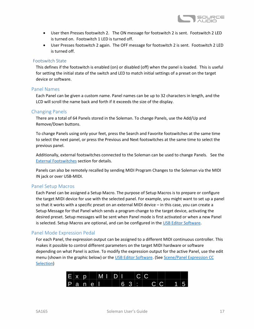
Panel Mode Expression Pedal For each Panel, the expression output can be assigned to a different MIDI continuous controller. This
makes it possible to control different parameters on the target MIDI hardware or software
depending on what Panel is active. To modify the expression output for the active Panel, use the edit
menu (shown in the graphic below) or the USB Editor Software. (See Scene/Panel Expression CC
Selection)
E x p M I D I C C
P a n e l 6 3 : C C 1 5

SA165 Soleman User’s Guide 18
Macros Macros are strings of MIDI messages that can consist of any type of MIDI message, including System
Exclusive (SysEx) messages and other non-standard MIDI message types. Macros allow users to
output custom MIDI data from the Soleman that greatly expands the flexibility of the Soleman for
use in different MIDI applications. The Soleman can store 127 macros, each of which can be up to 50
data bytes in length.
Typical MIDI messages consist of 1, 2, or 3 bytes. For example, a MIDI Clock message contains only
one byte. A Program Change message consists of 2 bytes. Note On, Note Off, and Continuous Control
messages consist of 3 bytes. In a macro, a variety of different message types can be strung together
in a sequence – any combination is necessary, as long as the total length of the Macro does not
exceed 50 bytes.
For example, it is possible to define a Macro that outputs a Note On Message on channel 3, a
Program Change message on channel 5, a Continuous Control Message on channel 12, and a SysEx
message. Then, that Macro could be assigned to, for example, Scene 5. So, any time Scene 5 is
activated in Scene Mode or List Mode, the MIDI Outputs would send all of those MIDI messages at
once.
Macros can be used in Scenes, as Panel Setup Messages, or even as On or Off messages for an
individual footswitch in Panel Mode. A single Macro can be reused in several different places at the
same time. So, for example, a single Macro could be assigned to multiple Scenes or even multiple
Panels, all at the same time.
Macros consist of an ID number, a name, and data (a list of MIDI messages). The macro ID is a
number between 0 and 126 that defines the macro so that it can be assigned to scenes, panels, and
footswitches. The macro name is not displayed on the Soleman’s LCD, but can be useful when
organizing and managing macros using the USB Editor Software.
To create and edit Macros, a little bit of MIDI knowledge is necessary, but the power of Macros
makes it worth learning! For more information, refer to MIDI Message Types.
To create Macros and assign them to scenes, panels, and footswitches, use the USB Editor Software.
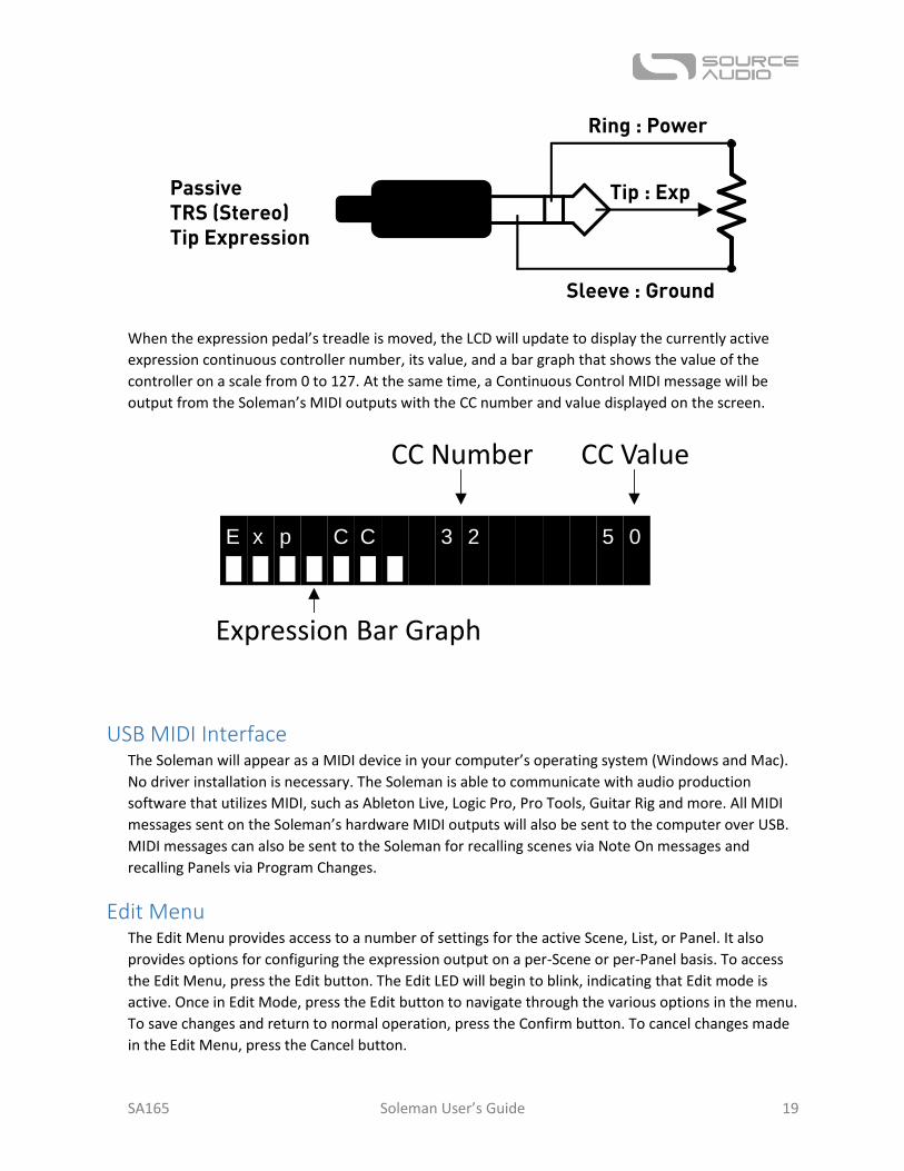
Expression Pedal The ¼” TRS Expression Input accepts passive expression pedals with power on the ring contact and
expression on the tip contact. Expression pedals with a linear taper are preferred since the input
digital converter on the Soleman is linear. Expression pedals with an audio/logarithmic taper are not
recommended. A variety of potentiometer values are supported due to the Soleman’s Expression
Calibration feature.
The following graphic shows the connections on the ¼” TRS cable that should be used to connect to
the expression pedal.
SA165 Soleman User’s Guide 19
When the expression pedal’s treadle is moved, the LCD will update to display the currently active
expression continuous controller number, its value, and a bar graph that shows the value of the
controller on a scale from 0 to 127. At the same time, a Continuous Control MIDI message will be
output from the Soleman’s MIDI outputs with the CC number and value displayed on the screen.
USB MIDI Interface The Soleman will appear as a MIDI device in your computer’s operating system (Windows and Mac).
No driver installation is necessary. The Soleman is able to communicate with audio production
software that utilizes MIDI, such as Ableton Live, Logic Pro, Pro Tools, Guitar Rig and more. All MIDI
messages sent on the Soleman’s hardware MIDI outputs will also be sent to the computer over USB.
MIDI messages can also be sent to the Soleman for recalling scenes via Note On messages and
recalling Panels via Program Changes.
Edit Menu The Edit Menu provides access to a number of settings for the active Scene, List, or Panel. It also
provides options for configuring the expression output on a per-Scene or per-Panel basis. To access
the Edit Menu, press the Edit button. The Edit LED will begin to blink, indicating that Edit mode is
active. Once in Edit Mode, press the Edit button to navigate through the various options in the menu.
To save changes and return to normal operation, press the Confirm button. To cancel changes made
in the Edit Menu, press the Cancel button.
Sleeve : Ground
Ring : Power
Tip : ExpPassiveTRS (Stereo)Tip Expression
E x p C C 3 2 5 0
█ █ █ █ █ █ █
Expression Bar Graph
CC Number CC Value
SA165 Soleman User’s Guide 20
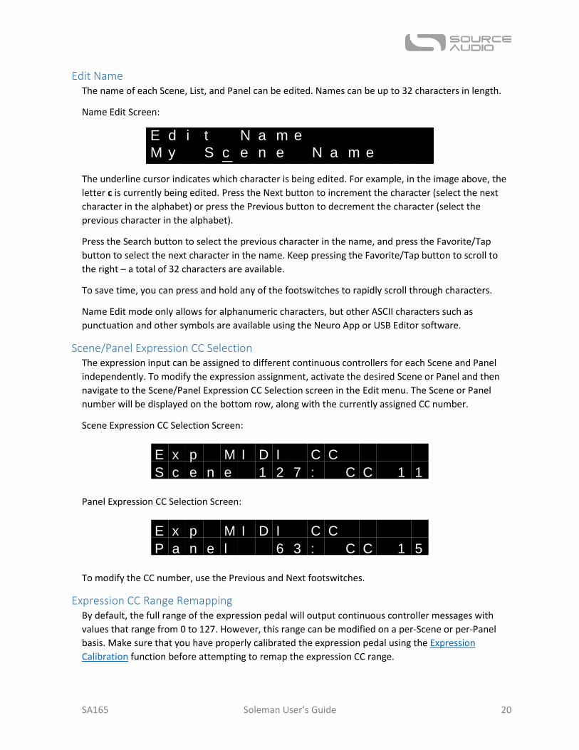
Edit Name The name of each Scene, List, and Panel can be edited. Names can be up to 32 characters in length.
Name Edit Screen:
The underline cursor indicates which character is being edited. For example, in the image above, the
letter c is currently being edited. Press the Next button to increment the character (select the next
character in the alphabet) or press the Previous button to decrement the character (select the
previous character in the alphabet).
Press the Search button to select the previous character in the name, and press the Favorite/Tap
button to select the next character in the name. Keep pressing the Favorite/Tap button to scroll to
the right – a total of 32 characters are available.
To save time, you can press and hold any of the footswitches to rapidly scroll through characters.
Name Edit mode only allows for alphanumeric characters, but other ASCII characters such as
punctuation and other symbols are available using the Neuro App or USB Editor software.
Scene/Panel Expression CC Selection The expression input can be assigned to different continuous controllers for each Scene and Panel
independently. To modify the expression assignment, activate the desired Scene or Panel and then
navigate to the Scene/Panel Expression CC Selection screen in the Edit menu. The Scene or Panel
number will be displayed on the bottom row, along with the currently assigned CC number.
Scene Expression CC Selection Screen:
Panel Expression CC Selection Screen:
To modify the CC number, use the Previous and Next footswitches.
Expression CC Range Remapping By default, the full range of the expression pedal will output continuous controller messages with
values that range from 0 to 127. However, this range can be modified on a per-Scene or per-Panel
basis. Make sure that you have properly calibrated the expression pedal using the Expression
Calibration function before attempting to remap the expression CC range.
E d i t N a m e
M y S c e n e N a m e
E x p M I D I C C
S c e n e 1 2 7 : C C 1 1
E x p M I D I C C
P a n e l 6 3 : C C 1 5
SA165 Soleman User’s Guide 21
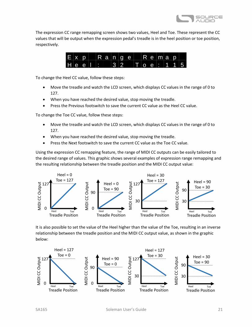
The expression CC range remapping screen shows two values, Heel and Toe. These represent the CC
values that will be output when the expression pedal’s treadle is in the heel position or toe position,
respectively.
To change the Heel CC value, follow these steps:
Move the treadle and watch the LCD screen, which displays CC values in the range of 0 to
127.
When you have reached the desired value, stop moving the treadle.
Press the Previous footswitch to save the current CC value as the Heel CC value.
To change the Toe CC value, follow these steps:
Move the treadle and watch the LCD screen, which displays CC values in the range of 0 to
127.
When you have reached the desired value, stop moving the treadle.
Press the Next footswitch to save the current CC value as the Toe CC value.
Using the expression CC remapping feature, the range of MIDI CC outputs can be easily tailored to
the desired range of values. This graphic shows several examples of expression range remapping and
the resulting relationship between the treadle position and the MIDI CC output value:
It is also possible to set the value of the Heel higher than the value of the Toe, resulting in an inverse
relationship between the treadle position and the MIDI CC output value, as shown in the graphic
below:
E x p R a n g e R e m a p
H e e l : 3 2 T o e : 1 1 5
127
0
Treadle PositionToeHeel
Heel = 0Toe = 127
MID
I CC
Ou
tpu
t
127
30
Treadle PositionToeHeel
Heel = 30Toe = 127
MID
I CC
Ou
tpu
t
90
0
Treadle PositionToeHeel
Heel = 0Toe = 90
MID
I CC
Ou
tpu
t
MID
I CC
Ou
tpu
t
90
30
Treadle PositionToeHeel
Heel = 90Toe = 30
127
0
Treadle PositionToeHeel
Heel = 127Toe = 0
MID
I CC
Ou
tpu
t
127
30
Treadle PositionToeHeel
Heel = 127Toe = 30
MID
I CC
Ou
tpu
t
90
0
Treadle PositionToeHeel
Heel = 90Toe = 0
MID
I CC
Ou
tpu
t
MID
I CC
Ou
tpu
t
90
30
Treadle PositionToeHeel
Heel = 30Toe = 90

SA165 Soleman User’s Guide 22
Global Edit Menu The Global Edit Menu provides access to a number of global settings that change the way the
Soleman works. To access the Global Edit Menu, press and hold the Edit button. The Edit LED will
begin to blink, indicating that Global Edit mode is active. Once in Global Edit Mode, press the Edit
button to navigate through the various options in the menu. To save changes and return to normal
operation, press the Confirm button. To cancel changes made in the Global Edit Menu, press the
Cancel button.
The following settings can be adjusted with the Global Edit Menu. See below for details:
Expression Pedal Calibration
Input MIDI Channel
Output MIDI Channel (default)
Favorite Scene (used in Scene and List modes)
Use Hub Names (Scene and List modes)
Function of Footswitch 4 (Favorite/Tap) in Scene Mode
Use large LCD digits (Scene mode only)
Send CC on Tap Tempo
Tap Tempo CC value
External Switch 1 Function
External Switch 2 Function
Factory Reset
Expression Calibration The Soleman uses a 10-bit ADC to convert external tip-hot passive expression pedals to MIDI data.
Because some expression pedals have different designs (for example, different potentiometer
resistances) and often differ due to manufacturing tolerances, it may be necessary to perform a
calibration to properly configure the Soleman for use with the connected expression pedal.
The expression calibration screen shows two numbers, Lo and Hi. These represent the lowest and
highest input voltages seen by the expression input, respectively. By default, the Lo value is set to 0
and the Hi value is set to 1023, representing the full range of the 10-bit ADC.
In reality, however, the expression pedal connected to the Soleman might not produce the full range
of voltages. In this case, the Soleman’s calibration feature can scale the expression pedal’s range to
match what the Soleman expects.
To perform a calibration, follow these steps:
Move the expression pedal’s treadle to its minimum position with the heel of the treadle all
the way down.
E x p C a l i b r a t i o n
L o : 1 1 1 H i : 8 9 5

SA165 Soleman User’s Guide 23
Remove your foot from the expression pedal and make sure the expression pedal is in its
natural resting position.
Tap the Previous footswitch to set the Lo calibration point.
Move the expression pedal’s treadle to its maximum position with the toe of the treadle all
the way down.
Remove your foot from the expression pedal and make sure the expression pedal is in its
natural resting position.
Tap the Next footswitch to set the Hi calibration point.
After you have completed these steps, the calibration should be complete. Press the Confirm button
to save changes.
IMPORTANT! In order to function correctly, the Lo value must always be smaller than the Hi value.
It is possible to create “dead zones” on either side of the expression pedal’s range of motion. To do
so, simply limit the range of motion you use during the calibration process. To create a “dead zone”
in the heel position, for example, depress the heel of the treadle about 90% of the way (as desired)
and then press the Previous footswitch to set the Lo calibration point. This means that the expression
pedal will be at its lowest value slightly before the heel of the treadle is completely depressed. You
can also use this method for the Hi calibration point to create a “dead zone” in the toe position.
Global Input MIDI Channel The Global MIDI Channel determines the MIDI channel for the MIDI input on the Soleman. The same
channel applies using the 5-pin DIN hardware jack and the USB-MIDI interface. The Soleman will
respond to Program Changes and Note ON messages that are sent to it to recall individual Panels and
Scenes, respectively.
To modify the Global MIDI Channel, use the Previous and Next footswitches.
Full range of motion
Upper dead zone
Calibrated range of motion
Lower dead zoneMinimum calibrated point
Maximum calibrated point
M I D I C h a n n e l I N
( G l o b a l ) : 1
SA165 Soleman User’s Guide 24
Global Output MIDI Channel (default) This sets the default output MIDI Channel to be used with all Scenes. In most cases, users will want
all scenes to use the same MIDI channel for all Program Changes and Continuous Controllers set up
using the Expression Pedal. This default MIDI channel is set with the Global Output MIDI Channel. In
Panel mode, the default Global Output MIDI Channel is used with the expression pedal settings. If
desired, the MIDI channel can be overridden on a per Scene or per Panel basis.
To modify the Global MIDI Channel, use the Previous and Next footswitches.
Favorite Scene The Favorite Scene can be recalled in Scene Mode and List Mode by tapping the Favorite footswitch.
Any Scene (from 0 to 127) can be selected as the Favorite Scene.
To modify the Favorite Scene, use the Previous and Next footswitches.
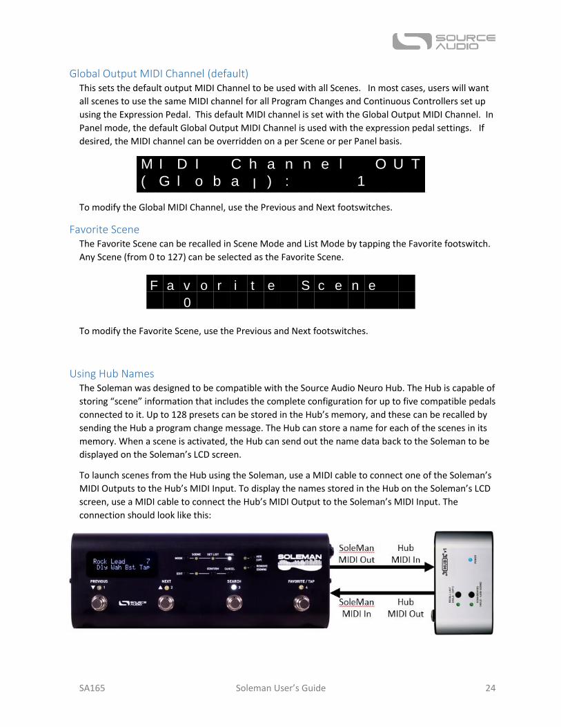
Using Hub Names The Soleman was designed to be compatible with the Source Audio Neuro Hub. The Hub is capable of
storing “scene” information that includes the complete configuration for up to five compatible pedals
connected to it. Up to 128 presets can be stored in the Hub’s memory, and these can be recalled by
sending the Hub a program change message. The Hub can store a name for each of the scenes in its
memory. When a scene is activated, the Hub can send out the name data back to the Soleman to be
displayed on the Soleman’s LCD screen.
To launch scenes from the Hub using the Soleman, use a MIDI cable to connect one of the Soleman’s
MIDI Outputs to the Hub’s MIDI Input. To display the names stored in the Hub on the Soleman’s LCD
screen, use a MIDI cable to connect the Hub’s MIDI Output to the Soleman’s MIDI Input. The
connection should look like this:
M I D I C h a n n e l O U T
( G l o b a l ) : 1
F a v o r i t e S c e n e
0
SA165 Soleman User’s Guide 25
After the MIDI cable connections have been made, navigate to the “Use Hub Names” screen in the
Edit Menu and use the Previous/Next footswitches to set the value to “Yes.”
Now, when the Soleman launches scenes on the Hub in Scene Mode, the corresponding name will be
sent from the Hub and displayed on the Soleman’s LCD screen.
IMPORTANT! When using the Use Hub Names mode, the Neuro Hub must be set to use its MIDI Out
jack as a MIDI output and NOT as a MIDI Through. The MIDI through will just reflect MIDI data back
to the Soleman and cause confusion!
Scene Mode Footswitch 4 Function In Scene mode, footswitch 4 can be used for either enabling Favorite Mode or as a Tap Tempo switch.
This is set globally using the Scene Mode-Footswitch 4 Function parameter. Since this is a Global
Option, the setting will be the same for all Scenes.
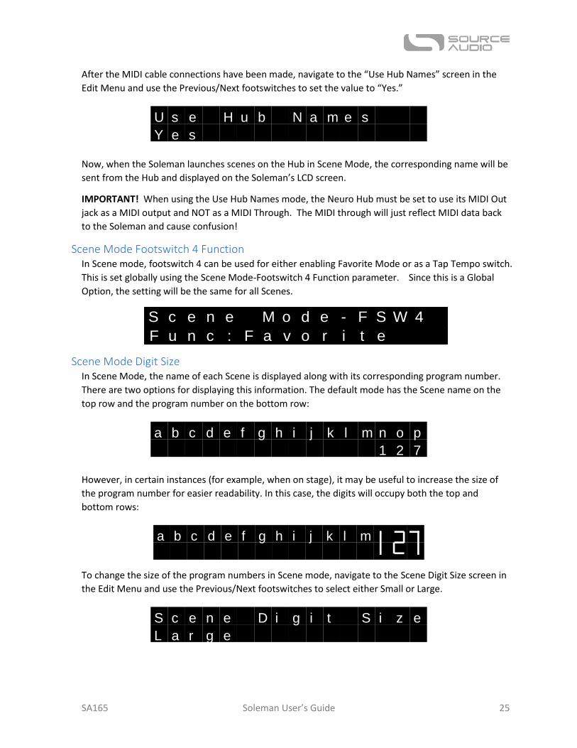
Scene Mode Digit Size In Scene Mode, the name of each Scene is displayed along with its corresponding program number.
There are two options for displaying this information. The default mode has the Scene name on the
top row and the program number on the bottom row:
However, in certain instances (for example, when on stage), it may be useful to increase the size of
the program number for easier readability. In this case, the digits will occupy both the top and
bottom rows:
To change the size of the program numbers in Scene mode, navigate to the Scene Digit Size screen in
the Edit Menu and use the Previous/Next footswitches to select either Small or Large.
U s e H u b N a m e s
Y e s
S c e n e M o d e - F S W 4
F u n c : F a v o r i t e
a b c d e f g h i j k l m n o p
1 2 7
a b c d e f g h i j k l m
S c e n e D i g i t S i z e
L a r g e
SA165 Soleman User’s Guide 26
Use CC for Remote Tap Tempo As an alternative to outputting MIDI Clock, the Soleman can output Continuous Control messages
when the Tap Tempo Footswitch has been pressed, a setup commonly known as remote tap tempo.
Use this option when the receiving MIDI equipment is set up for remote tap tempo operation.
The CC controller number can be set using the Tap Tempo CC Val parameter.
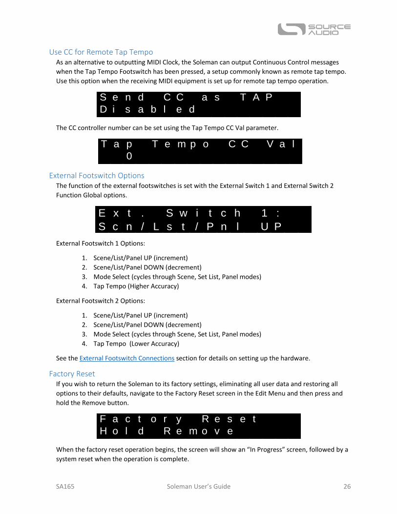
External Footswitch Options The function of the external footswitches is set with the External Switch 1 and External Switch 2
Function Global options.
External Footswitch 1 Options:
1. Scene/List/Panel UP (increment)
2. Scene/List/Panel DOWN (decrement)
3. Mode Select (cycles through Scene, Set List, Panel modes)
4. Tap Tempo (Higher Accuracy)
External Footswitch 2 Options:
1. Scene/List/Panel UP (increment)
2. Scene/List/Panel DOWN (decrement)
3. Mode Select (cycles through Scene, Set List, Panel modes)
4. Tap Tempo (Lower Accuracy)
See the External Footswitch Connections section for details on setting up the hardware.
Factory Reset If you wish to return the Soleman to its factory settings, eliminating all user data and restoring all
options to their defaults, navigate to the Factory Reset screen in the Edit Menu and then press and
hold the Remove button.
When the factory reset operation begins, the screen will show an “In Progress” screen, followed by a
system reset when the operation is complete.
S e n d C C a s T A P
D i s a b l e d
T a p T e m p o C C V a l
0
E x t . S w i t c h 1 :
S c n / L s t / P n l U P
F a c t o r y R e s e t
H o l d R e m o v e
SA165 Soleman User’s Guide 27
WARNING! A factory reset will delete ALL user data, including all Scenes, Lists, Panels, and Macros.
Be very cautious not to perform a factory reset unless you are willing to lose all of your user data!
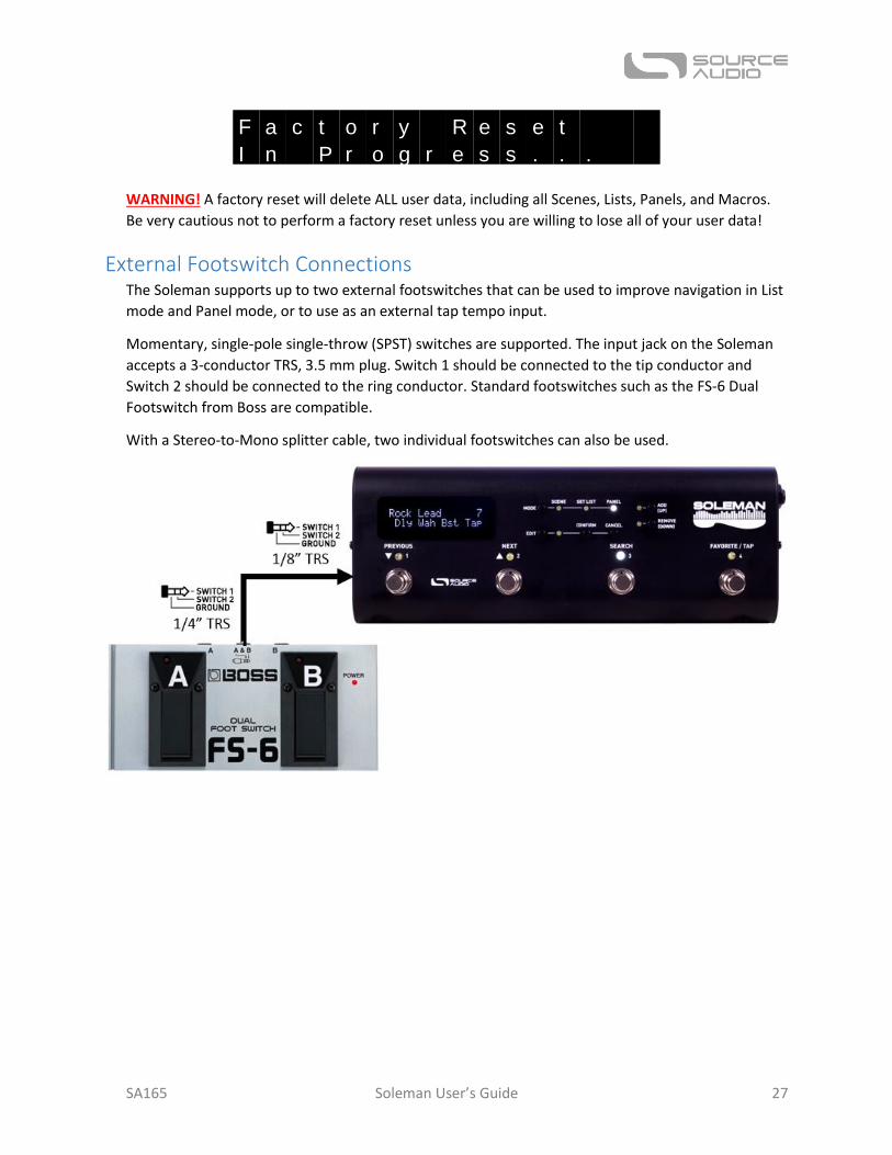
External Footswitch Connections The Soleman supports up to two external footswitches that can be used to improve navigation in List
mode and Panel mode, or to use as an external tap tempo input.
Momentary, single-pole single-throw (SPST) switches are supported. The input jack on the Soleman
accepts a 3-conductor TRS, 3.5 mm plug. Switch 1 should be connected to the tip conductor and
Switch 2 should be connected to the ring conductor. Standard footswitches such as the FS-6 Dual
Footswitch from Boss are compatible.
With a Stereo-to-Mono splitter cable, two individual footswitches can also be used.
F a c t o r y R e s e t
I n P r o g r e s s . . .
SA165 Soleman User’s Guide 28
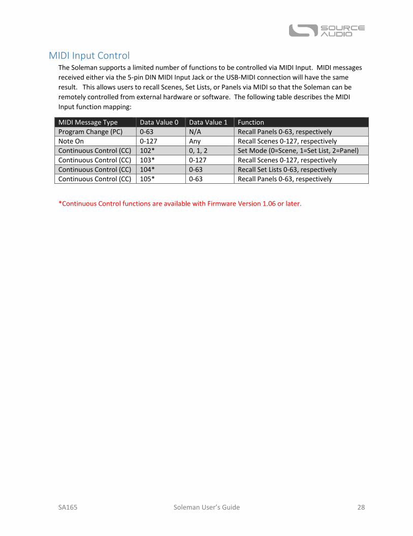
MIDI Input Control The Soleman supports a limited number of functions to be controlled via MIDI Input. MIDI messages
received either via the 5-pin DIN MIDI Input Jack or the USB-MIDI connection will have the same
result. This allows users to recall Scenes, Set Lists, or Panels via MIDI so that the Soleman can be
remotely controlled from external hardware or software. The following table describes the MIDI
Input function mapping:
MIDI Message Type Data Value 0 Data Value 1 Function
Program Change (PC) 0-63 N/A Recall Panels 0-63, respectively
Note On 0-127 Any Recall Scenes 0-127, respectively
Continuous Control (CC) 102* 0, 1, 2 Set Mode (0=Scene, 1=Set List, 2=Panel)
Continuous Control (CC) 103* 0-127 Recall Scenes 0-127, respectively
Continuous Control (CC) 104* 0-63 Recall Set Lists 0-63, respectively
Continuous Control (CC) 105* 0-63 Recall Panels 0-63, respectively
*Continuous Control functions are available with Firmware Version 1.06 or later.
SA165 Soleman User’s Guide 29
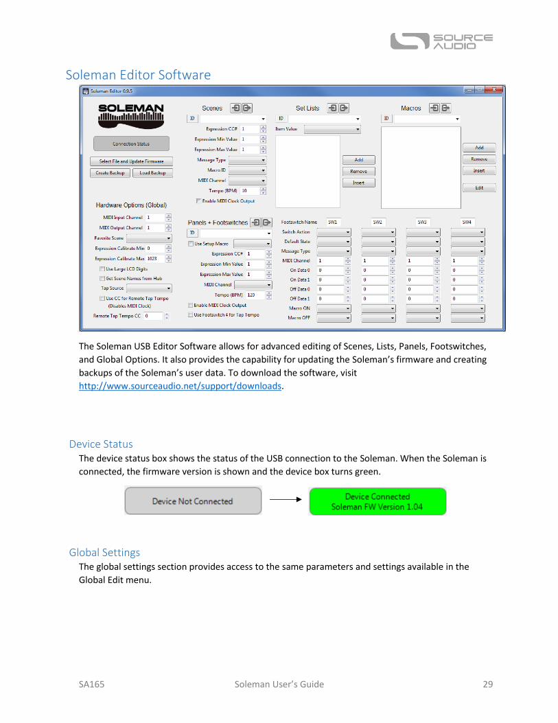
Soleman Editor Software
The Soleman USB Editor Software allows for advanced editing of Scenes, Lists, Panels, Footswitches,
and Global Options. It also provides the capability for updating the Soleman’s firmware and creating
backups of the Soleman’s user data. To download the software, visit
http://www.sourceaudio.net/support/downloads.
Device Status The device status box shows the status of the USB connection to the Soleman. When the Soleman is
connected, the firmware version is shown and the device box turns green.
Global Settings The global settings section provides access to the same parameters and settings available in the
Global Edit menu.
SA165 Soleman User’s Guide 30
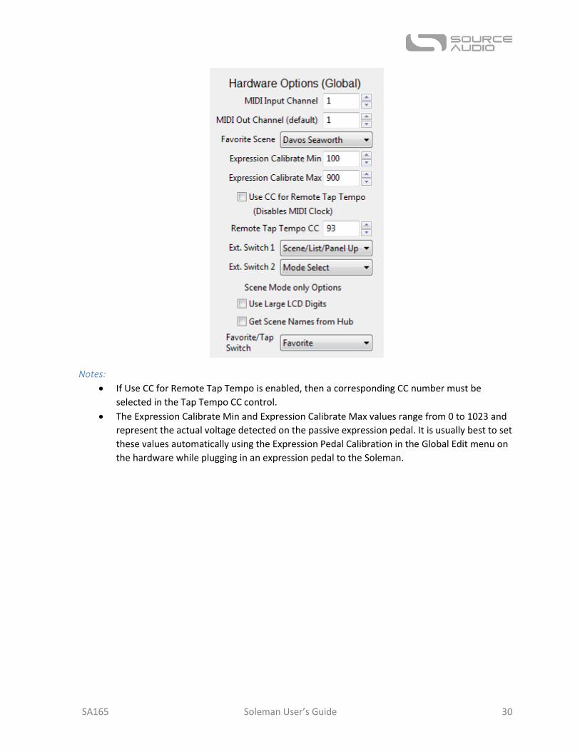
Notes:
If Use CC for Remote Tap Tempo is enabled, then a corresponding CC number must be
selected in the Tap Tempo CC control.
The Expression Calibrate Min and Expression Calibrate Max values range from 0 to 1023 and
represent the actual voltage detected on the passive expression pedal. It is usually best to set
these values automatically using the Expression Pedal Calibration in the Global Edit menu on
the hardware while plugging in an expression pedal to the Soleman.
SA165 Soleman User’s Guide 31
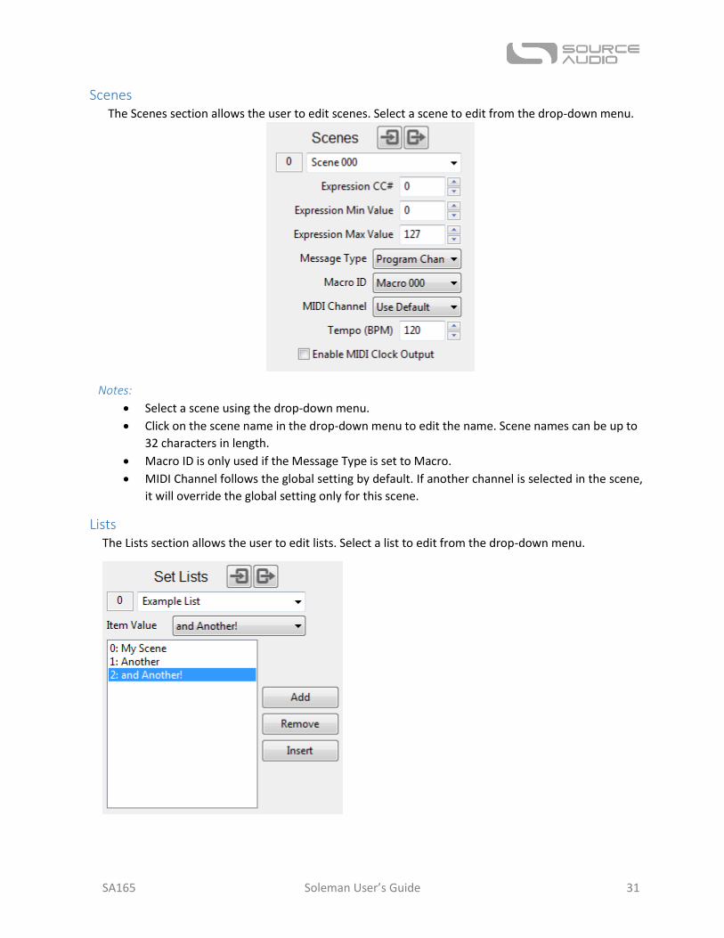
Scenes The Scenes section allows the user to edit scenes. Select a scene to edit from the drop-down menu.
Notes:
Select a scene using the drop-down menu.
Click on the scene name in the drop-down menu to edit the name. Scene names can be up to
32 characters in length.
Macro ID is only used if the Message Type is set to Macro.
MIDI Channel follows the global setting by default. If another channel is selected in the scene,
it will override the global setting only for this scene.
Lists The Lists section allows the user to edit lists. Select a list to edit from the drop-down menu.
SA165 Soleman User’s Guide 32
Notes:
Select a list using the drop-down menu.
Click on the list name in the drop-down menu to edit the name. List names can be up to 32
characters in length.
To edit a scene in the list, click on it to highlight it, and then use the List Item Value control
to change its value.
To add a scene to the end of the list, use the List Item Value control to set the value, then
click the Add button.
To remove a scene from the list, click the scene to highlight it, then click the Remove button
to remove it.
To insert a scene before another scene in the list, click a scene to highlight it, use the List
Item Value control to set the value, then click the Insert button.
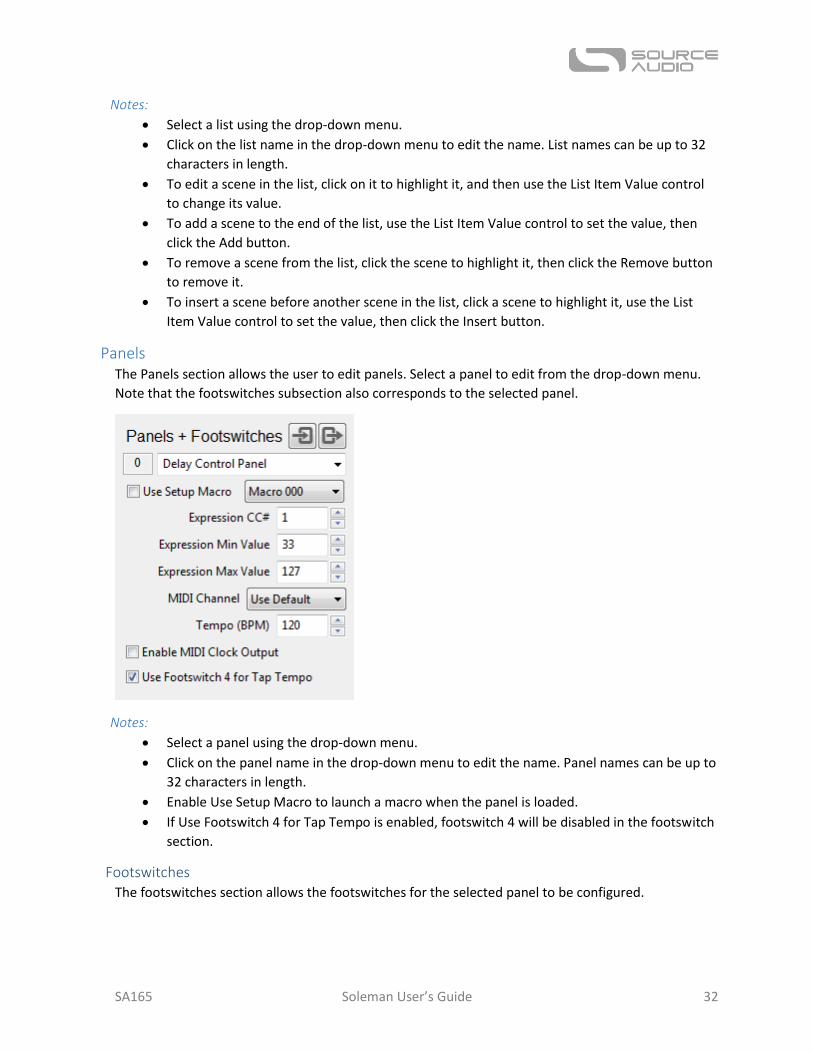
Panels The Panels section allows the user to edit panels. Select a panel to edit from the drop-down menu.
Note that the footswitches subsection also corresponds to the selected panel.
Notes:
Select a panel using the drop-down menu.
Click on the panel name in the drop-down menu to edit the name. Panel names can be up to
32 characters in length.
Enable Use Setup Macro to launch a macro when the panel is loaded.
If Use Footswitch 4 for Tap Tempo is enabled, footswitch 4 will be disabled in the footswitch
section.
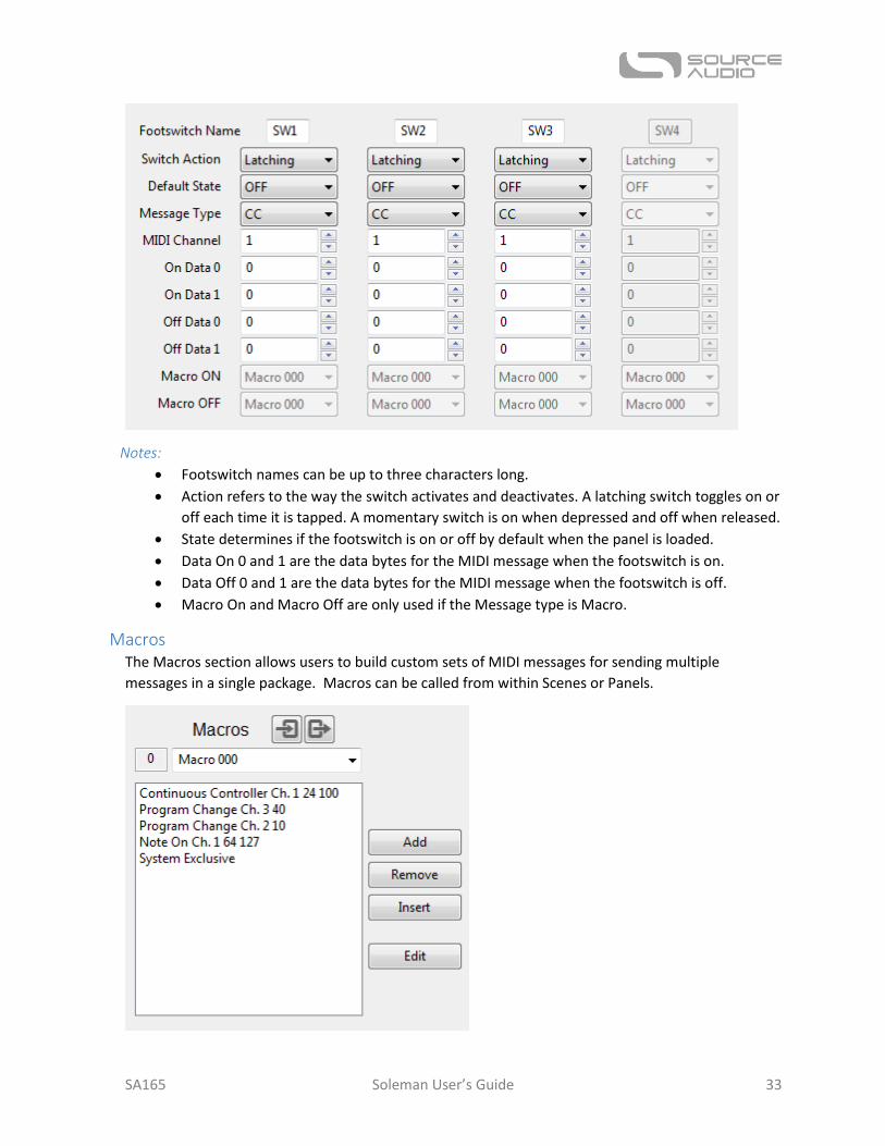
Footswitches The footswitches section allows the footswitches for the selected panel to be configured.
SA165 Soleman User’s Guide 33
Notes:
Footswitch names can be up to three characters long.
Action refers to the way the switch activates and deactivates. A latching switch toggles on or
off each time it is tapped. A momentary switch is on when depressed and off when released.
State determines if the footswitch is on or off by default when the panel is loaded.
Data On 0 and 1 are the data bytes for the MIDI message when the footswitch is on.
Data Off 0 and 1 are the data bytes for the MIDI message when the footswitch is off.
Macro On and Macro Off are only used if the Message type is Macro.
Macros The Macros section allows users to build custom sets of MIDI messages for sending multiple
messages in a single package. Macros can be called from within Scenes or Panels.
SA165 Soleman User’s Guide 34
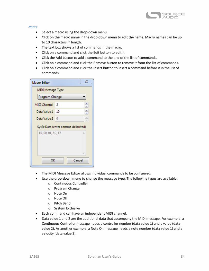
Notes:
Select a macro using the drop-down menu.
Click on the macro name in the drop-down menu to edit the name. Macro names can be up
to 10 characters in length.
The text box shows a list of commands in the macro.
Click on a command and click the Edit button to edit it.
Click the Add button to add a command to the end of the list of commands.
Click on a command and click the Remove button to remove it from the list of commands.
Click on a command and click the Insert button to insert a command before it in the list of
commands.
The MIDI Message Editor allows individual commands to be configured.
Use the drop-down menu to change the message type. The following types are available:
o Continuous Controller
o Program Change
o Note On
o Note Off
o Pitch Bend
o System Exclusive
Each command can have an independent MIDI channel.
Data value 1 and 2 are the additional data that accompany the MIDI message. For example, a
Continuous Controller message needs a controller number (data value 1) and a value (data
value 2). As another example, a Note On message needs a note number (data value 1) and a
velocity (data value 2).

SA165 Soleman User’s Guide 35
System Exclusive messages require the user to type in the data directly into the Systex Data
text box. Data must be formatted as hexadecimal values, and each byte must be separated
from the next byte using a comma. For example a valid Sysex message is F0, 00, 01, 6C, F7.
SA165 Soleman User’s Guide 36
Appendix
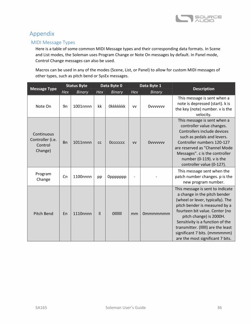
MIDI Message Types Here is a table of some common MIDI Message types and their corresponding data formats. In Scene
and List modes, the Soleman uses Program Change or Note On messages by default. In Panel mode,
Control Change messages can also be used.
Macros can be used in any of the modes (Scene, List, or Panel) to allow for custom MIDI messages of
other types, such as pitch bend or SysEx messages.
Message Type Status Byte Data Byte 0 Data Byte 1
Description Hex Binary Hex Binary Hex Binary
Note On 9n 1001nnnn kk 0kkkkkkk vv 0vvvvvvv
This message is sent when a note is depressed (start). k is
the key (note) number. v is the velocity.
Continuous Controller (i.e.
Control Change)
Bn 1011nnnn cc 0ccccccc vv 0vvvvvvv
This message is sent when a controller value changes.
Controllers include devices such as pedals and levers.
Controller numbers 120-127 are reserved as "Channel Mode Messages". c is the controller
number (0-119). v is the controller value (0-127).
Program Change
Cn 1100nnnn pp 0ppppppp - - This message sent when the
patch number changes. p is the new program number.
Pitch Bend En 1110nnnn ll 0lllllll mm 0mmmmmmm
This message is sent to indicate a change in the pitch bender
(wheel or lever, typically). The pitch bender is measured by a fourteen bit value. Center (no
pitch change) is 2000H. Sensitivity is a function of the transmitter. (llllll) are the least significant 7 bits. (mmmmmm) are the most significant 7 bits.
SA165 Soleman User’s Guide 37
Specifications
Dimensions Length: 26.67 cm (10.5 inches)
Width: 9.53 cm (3.75 inches)
Height: 7.00 cm (2.75 inches)
Weight 1 kilogram (2.2 pounds)
Power 70 mA @ 9V DC negative tip (positive sleeve) barrel power jack, 2.1 mm inner diameter, 5.5 mm
outer diameter
5V DC bus power (USB)
Firmware Updates USB Editor Firmware Update: Over time, new features may be added to the Soleman via firmware
updates. Firmware updates will be made available on the Source Audio website. To update the
firmware, connect the Soleman to the computer using a USB cable and use the Firmware Update
function in the USB Editor Software.
Waste Disposal Notes
If possible, dispose of the device at an electronics recycling center. Do not dispose of the device with
the household waste.
For full compliance with EN 61000-4-6 standard, input cable must be less than 3 meters in length.
SA165 Soleman User’s Guide 38
Warranty
Limited Transferrable Warranty Source Audio, LLC (hereinafter “Source Audio”) warrants that your new Source Audio Soleman MIDI
Foot Controller, when purchased at an authorized Source Audio dealer in the United States of
America (“USA”), shall be free from defects in materials and workmanship under normal use for a
period of two (2) years from the date of purchase by the original purchaser. Please contact your
dealer for information on warranty and service outside of the USA.
Under this Limited Warranty, Source Audio’s sole obligation and the purchaser’s sole remedy shall be
repair, replacement, or upgrade, at Source Audio’s sole discretion, of any product that, if properly
used and maintained, proves to be defective upon inspection by Source Audio. Source Audio reserves
the right to update any unit returned for repair and to change or improve the design of the product
at any time without notice. Source Audio reserves the right to use reconditioned parts and
assemblies as warranty replacements for authorized repairs. Any product repaired, replaced, or
upgraded pursuant to this Limited Warranty will be warranted for the remainder of the original
warranty period.
This Limited Warranty is extended to the original retail purchaser. This Limited Warranty can be
transferred to anyone who may subsequently purchase this product provided that such transfer is
made within the applicable warranty period and Source Audio is provided with all of the following
information: (i) all warranty registration information (as set forth on the registration card) for the
new owner, (ii) proof of the transfer, within thirty (30) days of the transfer, and (iii) a photocopy of
the original sales receipt. Warranty coverage shall be determined by Source Audio in its sole
discretion. This is your sole warranty. Source Audio does not authorize and third party, including any
dealer or sales representatives, to assume any liability on behalf of Source Audio or to make any
warranty on behalf of Source Audio.
Warranty Information Source Audio may, at its option, require proof of the original purchase date in the form of a dated
copy of the original authorized dealer’s invoice or sales receipt. Service and repairs of Source Audio
products are to be performed only at the Source Audio factory or a Source Audio authorized service
center. Prior to service or repair under this Limited Warranty, the purchaser must request from
Source Audio a return authorization, which is available at:
Source Audio LLC
120 Cummings Park, Woburn, MA 01801
(781) 932-8080 or at www.sourceaudio.net
Unauthorized service, repair, or modification will void this Limited Warranty.
Disclaimer and Limitation of Warranty Do not open the effects pedal under any circumstance. This will void the warranty.
The foregoing limited warranty is the only warranty given by Source Audio and is in lieu of all other
warranties. All implied warranties, including warranties of merchantability and fitness for any
particular purpose, exceeding the specific provisions of this limited warranty, are hereby disclaimed

SA165 Soleman User’s Guide 39
and excluded from this limited warranty. Upon expiration of the applicable express warranty period,
Source Audio shall have no further warranty obligation of any kind, express or implied. Source Audio
shall in no event be liable for any special, incidental, or consequential damages suffered by the
purchaser or any third party, including without limitation, damages for loss of profits or business or
damages resulting from use or performance of the product, whether in contract or in tort. Source
Audio shall not be liable for any expenses, claims, or suits arising out of or relating to any of the
foregoing. Some states do not allow the exclusion or limitation of implied warranties so some of the
above limitations and exclusions may not apply to you. This Limited Warranty gives you specific legal
rights, and you may also have other rights, which vary, from state to state. This Limited Warranty
only applies to products sold and used in the USA. Source Audio shall not be liable for damages or
loss resulting from the negligent or intentional acts of the shipper or its contracted affiliates. You
should contact the shipper for proper claims procedures in the event of damage or loss resulting
from shipment.
Version History July 13, 2016: Initial Release
August 8, 2016: Added MIDI Input Table
©Source Audio LLC | 120 Cummings Park, Woburn, MA 01801 | www.sourceaudio.net