software technology readiness assessment - dtic. · pdf filesoftware technology readiness...
TRANSCRIPT

Software Technology Readiness AssessmentDefense Acquisition Guidance with Space Examples
Dr. Peter HantosThe Aerospace Corporationp p
2010 Systems and Software Technology Conference, June 8-11, 2010
© The Aerospace Corporation 2010

Report Documentation Page Form ApprovedOMB No. 0704-0188
Public reporting burden for the collection of information is estimated to average 1 hour per response, including the time for reviewing instructions, searching existing data sources, gathering andmaintaining the data needed, and completing and reviewing the collection of information. Send comments regarding this burden estimate or any other aspect of this collection of information,including suggestions for reducing this burden, to Washington Headquarters Services, Directorate for Information Operations and Reports, 1215 Jefferson Davis Highway, Suite 1204, ArlingtonVA 22202-4302. Respondents should be aware that notwithstanding any other provision of law, no person shall be subject to a penalty for failing to comply with a collection of information if itdoes not display a currently valid OMB control number.
1. REPORT DATE APR 2010 2. REPORT TYPE
3. DATES COVERED 00-00-2010 to 00-00-2010
4. TITLE AND SUBTITLE Software Technology Readiness Assessment. Defense AcquisitionGuidance with Space Examples
5a. CONTRACT NUMBER
5b. GRANT NUMBER
5c. PROGRAM ELEMENT NUMBER
6. AUTHOR(S) 5d. PROJECT NUMBER
5e. TASK NUMBER
5f. WORK UNIT NUMBER
7. PERFORMING ORGANIZATION NAME(S) AND ADDRESS(ES) The Aerospace Corporation,P.O. Box 92957-M1/112,Los Angeles,CA,90009-2957
8. PERFORMING ORGANIZATIONREPORT NUMBER
9. SPONSORING/MONITORING AGENCY NAME(S) AND ADDRESS(ES) 10. SPONSOR/MONITOR’S ACRONYM(S)
11. SPONSOR/MONITOR’S REPORT NUMBER(S)
12. DISTRIBUTION/AVAILABILITY STATEMENT Approved for public release; distribution unlimited
13. SUPPLEMENTARY NOTES Presented at the 22nd Systems and Software Technology Conference (SSTC), 26-29 April 2010, Salt LakeCity, UT. Sponsored in part by the USAF. U.S. Government or Federal Rights License
14. ABSTRACT
15. SUBJECT TERMS
16. SECURITY CLASSIFICATION OF: 17. LIMITATION OF ABSTRACT Same as
Report (SAR)
18. NUMBEROF PAGES
82
19a. NAME OFRESPONSIBLE PERSON
a. REPORT unclassified
b. ABSTRACT unclassified
c. THIS PAGE unclassified
Standard Form 298 (Rev. 8-98) Prescribed by ANSI Std Z39-18

About Your InstructorDr. Peter HantosSenior Engineering SpecialistThe Aerospace CorporationP.O. Box 92957-M1/112Los Angeles, CA 90009-2957Phone: (310) 336-1802EMail: [email protected]
Degrees Received:gDoctorate in Automation, Technical University, Budapest, HungaryM.S. in Electrical Engineering, Technical University, Budapest, Hungary
Industry Experience:Over 35 years of combined experience as professor, researcher, software engineer and manager, with accomplishments insoftware engineering manufacturing automation office automation and signal processing As a senior software engineer atsoftware engineering, manufacturing automation, office automation and signal processing. As a senior software engineer atXerox he was member of the original development team that was chartered to bring into the product development domain theworld-known inventions from the Xerox Palo Alto Research Center (PARC), primarily the use of the desktop, icons, mouse-control and network paradigms. Successfully directed engineering and quality process development on all levels of theenterprise. As principal scientist of the Xerox Corporate Software Engineering Center developed and implemented twocorporate-wide processes for software-intensive product development and the assessment of software technology readinessf d ti ti I th it h l i l t d t id ft i k tfor productization. In the same capacity he also implemented a corporate-wide software risk assessment program.
Government/Defense Program Support Experience:NASA, FBI, CIA, Space Based Infra-Red System (SBIRS), Global Positioning System (GPS), Space Radar (SR), and NationalSystems Group Customers of The Aerospace Corporation
Teaching Experience:GSAW 2005, 2006, 2007, 2008, 2009, 2010 Tutorials; Euro-SEPG 2005, INCOSE 2005, NDIA 2008 and 2009 Tutorials;“Space System Software Project Management”, “Space System Software Acquisition Management”, “Space System SoftwareProduct Development”, “Space System Development, Integration, & Test”, “Introduction to Program Office Data and Controls”,and “Program Measurement Workshop” courses for The Aerospace Institute; Electrical Engineering and Computer Sciencecourses at the Technical University Budapest Hungary and at the University of California Santa Barbara (UCSB)courses at the Technical University, Budapest, Hungary, and at the University of California, Santa Barbara (UCSB).Dr. Hantos has also been authorized by the SEI to teach the “Introduction to CMMI®-DEV V1.2” SEI Course.
2

Acknowledgements
• This work would not have been possible without the help of the following people of The Aerospace Corporation
– Suellen Eslinger– Dr Robert FrueholzDr. Robert Frueholz– Dr. Leslie Holloway
• A special thanks goes to the members of the Air Force Smart Operations f th 21 t C t /D l d S t i W fi hti S t /for the 21st Century/Develop and Sustain Warfighting Systems/ Technology Development Team
– Dr. Thomas Christian (AFMC/ASC) ( )– Suzanne Garcia (SEI) – William Nolte (AFMC/AFRL)
Dr Paul Phister (AFMC/AFRL)– Dr. Paul Phister (AFMC/AFRL)– Dr. Kyle Yang (MIT/Lincoln Lab)
3

The Technology Readiness Challenge
When the nation's first ballistic missile rose about 6 inches above the launch pad before toppling over and exploding,
<Simon> Ramo reportedly turned to an Air Force general and said: "Well, Benny, now that we know the thing can fly, all we y g y
have to do is improve its range a bit.”~~~ Book Review, LA Times, July 5, 2009, B4 Business, by Peter Pae
(Simon Ramo was the co-founder of and the "R" in TRW Corporation now part of Northrop
4
(Simon Ramo was the co founder of and the R in TRW Corporation, now part of Northrop Grumman Corporation; TRW was acquired together with Litton, Westinghouse, Logicon, etc.)

Outline
• Motivation• Technology Readiness Assessments – the 64,000-foot Viewgy• Technology Readiness Assessments – the 10,000-foot View• Software Technology Readiness Definitions• Emerging Software Technologies to Watch• Algorithms• Environmental Considerations• What Can We Learn from the Software Architecture?• Selected, High-Level Viewpoints for Technology Readiness Assessment• Critical Technology Element Identification Questions• Software Technology Readiness Determination• Case Studies
– Space Vehicle: Software Critical Technology Element Identification for a Space Vehicle– Ground System: Is Service-Oriented Architecture (SOA) a Critical Technology Element?
Ch ll i T i• Challenging Topics• Concluding Thoughts• Acronyms
R f• References • Backup Slides
5

Motivation
• Why is Technology Readiness Assessment important?“The inability to define and thus measure technology readiness facilitates– The inability to define and thus measure technology readiness facilitates decisions to incorporate immature technology in system design at Milestone B which consequently leads to technical problems during System Design and Development.” [DAPA 2006]
• Why should it be important for You?– For one thing, it is the Law (more on this later.) Nevertheless …– If you are in the Acquisition Program Office (APO):y q g ( )
• You might have to provide data to an Independent Review Team (IRT) conducting a Technology Readiness Assessment (TRA)
– If you are a Contractor:• You might want to gain insight into how your proposals are evaluated
– If you are in The Aerospace Corporation:• You might be invited to become a member of an IRTg
• What is my objective in preparing this course?– Guidance on this topic will always be inadequate due to the disruptive
nature of technology innovation. I want to encourage you to understand the underlying, core principles rather than just trying to follow the letter of the DOD Deskbook.
6

Technology Readiness Assessments –th 64 000 f t Vithe 64,000-foot View
• Public Law 109-163-Jan 6 2006 Section 801Public Law 109 163 Jan.6, 2006, Section 801TITLE VIII—ACQUISITION POLICY, ACQUISITION MANAGEMENT, AND RELATED MATTERS
Subtitle A—Provisions Relating to Major Defense Acquisition Programsg j f q gSEC. 801. REQUIREMENT FOR CERTIFICATION BEFORE MAJORDEFENSE ACQUISITION PROGRAM MAY PROCEED TO MILESTONE B.(a) CERTIFICATION REQUIREMENT.—Chapter 139 of title 10, United States Code, is amended by inserting after section 2366 the following new section:‘‘§ 2366a. Major defense acquisition programs: certification required before Milestone B or Key Decision Point B approval( ) CERTIFICATION A j d f i iti t i Mil t B(a) CERTIFICATION.—A major defense acquisition program may not receive Milestone B approval, or Key Decision Point B approval in the case of a space program, until the milestone decision authority certifies that—(1) the technology in the program has been demonstrated in a relevant environment; …”( ) gy p g ;
7
Note that the term “Key Decision Point” is not in use since the cancellation of NSSAP 03-01

Technology Readiness Assessments –th 64 000 f t Vi (C t )the 64,000-foot View (Cont.)
• November 2, 2007 Air Force Memorandum on Technology Certificationo e be , 00 o ce e o a du o ec o ogy Ce t cat o– Spells out that for all Critical Technology Elements (CTEs) it has to be
demonstrated in a relevant environment that they are at Technology Readiness Level (TRL) 6 or greater.
• New provisions in the Weapon Systems Acquisition Reform Act of 2009TITLE I—ACQUISITION ORGANIZATION
SEC 104 Assessment of technological maturity of critical technologies of major defenseSEC. 104. Assessment of technological maturity of critical technologies of major defense acquisition programs by the Director of Defense Research and Engineering.(a) ASSESSMENT BY DIRECTOR OF DEFENSE RESEARCH AND ENGINEERING.—
(1) IN GENERAL. — Section 139a of title 10, United States Code, is amended by adding at ( ) f y gthe end the following new subsection:
(c) (1) The Director of Defense Research and Engineering, in consultation with the Director of Developmental Test and Evaluation, shall periodically review and assess the technological maturity and integration risk of critical technologies of the major defensetechnological maturity and integration risk of critical technologies of the major defense acquisition programs …
(2) The Director shall submit to the Secretary of Defense and the congressional defense committees by March 1 of each year a report…
8

Basic Department of Defense (DOD) TRA Definitions
• The key document providing DOD guidance on carrying out a TRA is entitled the “Technology Readiness Assessment (TRA) Deskbook”
– This tutorial is based on the most recent, July 2009 edition• Technology Maturity
– A measure or degree to which proposed technologies meet programA measure or degree to which proposed technologies meet program objectives
• Technology Readiness Assessment– A TRA is a formal, systematic, metrics-based process and accompanyingA TRA is a formal, systematic, metrics based process and accompanying
report that assesses the maturity of critical hardware and software technologies to be used in systems. The TRA is not intended to predict future performance of the evaluated technologies, nor does it assess the quality of the system architecture design or integration planquality of the system architecture, design, or integration plan
• TRA is different from “Conventional” Risk Management– The result of a TRA is a single number on a 1-9, ordinal scale, called
Technology Readiness Level (TRL)Technology Readiness Level (TRL). – TRLs do not intend to reflect either the likelihood of attaining required
maturity or the impact of not achieving the required maturity• The TRA complements but does not in any way preclude the• The TRA complements – but does not in any way preclude – the
Program Manager’s responsibility to pursue reduction of all risks9

Critical Technology Elements
• Context for Technology Readiness AssessmentsF ti l t ll l d t h l i d– For practical purposes not all planned technologies are assessed• The technologies that are subject of a TRA will be called Critical
Technology Elements (CTEs)However the analysis of candidate technologies begins even before– However, the analysis of candidate technologies begins even before Materiel Development Decision takes place for the acquisition
• A technology element is critical if• The system being acquired depends on this technology element to meetThe system being acquired depends on this technology element to meet
operational requirements within acceptable cost and schedule limits, and• The technology element or its application is
– either new or novel, or– in an area that poses major technological risk during detailed design
or demonstration– Candidate CTEs vs. CTEs
• Until it is approved by the Milestone Decision Authority (MDA,) all CTEs are considered only as Candidate CTEs
– CTE identification data includes the criteria and rationale for declaring the CTE as critical or eliminating it as a CTE candidateCTE as critical or eliminating it as a CTE candidate
10

Technology Evaluation Logistics
Pre‐Systems Acquisition Systems AcquisitionTechnologyDevelopmentApproval
Engineering and Manufacturing DevelopmentApproval
Post‐CDRAssessment
Low‐RateInitial ProdApproval
Source SelectionDOD 5000.02 (2 December 2008)
JROCICD
A Bpp
Production and
Deployment
Materiel Solution Analysis
TechnologyDevelopment
Engineering and Manufacturing Development
Milestones: IOCC
SRRMateriel Development Decision
SFR PDR CDR TRR SVR
DDR&E‐conducted TRAs(Calendar‐Based)
Steps of a formal, IRT-conducted TRA at Milestones B and C
IRT‐conducted TRA(Event‐Based, Formal)
Submission by DDR&E(Event‐Based but Informal)
IRT‐conducted TRA(Event‐Based, Formal)
• The Component Science & Technology Executive appoints an IRT ofappropriate Subject Matter Experts (SMEs)
• Acquisition Program Office presents its technology plans to the IRTIRT l t th l d b it th li t f l t d CTE t th• IRT evaluates the plan and submits the list of selected CTEs to the Defense Acquisition Board (DAB) for approval
• IRT assesses the maturity of the approved CTEsIRT b i f th Mil t D i i A th it (MDA) it fi di
11
• IRT briefs the Milestone Decision Authority (MDA) on its findings• MDA approves/disapproves the entry to the next acquisition phase

Technology Readiness Assessments –th 10 000 f t Vithe 10,000-foot View
• Relevant Environment Definition– Relevant Environment is a validation environment that simulates key aspects
of the Operational Environment– The purpose of using a relevant environment is to demonstrate sufficientThe purpose of using a relevant environment is to demonstrate sufficient
confidence in the CTE; i.e., that skillful application of this technology will fully support the required threshold functionality.
• Relevant Environment for Space*Relevant Environment for Space– A satellite from launch to standard operation in space is exposed to
drastically changing environmental conditions and a relevant environment test design must encompass all such stressing aggregate conditions:test design must encompass all such stressing, aggregate conditions:• Space Environment• Launch Environment • Designed Environment This is where software “lives”• Operational Environment
*This is an experience based recommendation; unfortunately the DOD Deskbook does not
12
This is an experience-based recommendation; unfortunately the DOD Deskbook does not have adequate space-related guidance. For further details please see the backup slides.

Assessing CTEs using the TRL “Thermometer”
Actual system proven through successful mission operations TRL 9
Actual system completed and qualified through test and demonstrationSystem prototype demonstration in an operational environment
TRL 8
TRL 7 System prototype demonstration in an operational environment
System/subsystem model or prototype demonstration in a relevant environment
TRL 7
TRL 6TRL 6
Component and/or breadboard validation in relevant environment
Component and/or breadboard validation in laboratory environment
TRL 5TRL 5
TRL 4 p y
Analytical and experimental critical function and/or characteristic proof of concept
TRL 3
Technology concept and/or application formulated
Basic principles observed and reported
TRL 2
TRL 1
13
Before We Move On…
• Check o r nderstanding of the follo ing ne terms• Check your understanding of the following new terms
– IRT
– TRA
TRL– TRL
– CTE
– Relevant Environment
• O.K.?
14

Software Technology Readiness Definitions*
• The Definition of Software Technology – Software technology is defined as the theory and practice of various
sciences applied to software development, operation, understanding, and maintenance. Software Technology is any concept, process, method, algorithm or tool whose primary purpose is the development operationalgorithm, or tool whose primary purpose is the development, operation, understanding, and maintenance of software [Foreman 1997]
– Software technology examples• Technology directly used in the objective system• Technology directly used in the objective system
– E.g., two-tier and three-tier architecture, Service-Oriented Architecture (SOA,) Remote Procedure Calls (RPC)
T h l d i t l th t d i t i ft• Technology used in tools that produce or maintain software– E.g., Graphical User Interface (GUI) builders, programming
languages and compilers, cyclomatic complexity analyzers• Process technologies applied to produce or maintain software
– Personal Software Process (PSP), Cleanroom Software Engineering.
15
* Unfortunately, the TRA Deskbook does not have a definition of software technology

A Sampler of Emerging Software Technologies to Watch
• Technologies directly supporting mission requirements– Network Centric Warfare (NCW)
• NCW is a state-of-the art war-fighting theory with the following, two implementation dimensionsimplementation dimensions
– Network Centric Operations (NCO), dealing with the cognitive and social dimensions of NCWNetwork Centric Infrastructure (NCI) addressing physical and– Network Centric Infrastructure (NCI), addressing physical and information dimensions of NCW
• Note that NCW almost automatically puts every weapon system in a System of Systems (SOS) contextSystem of Systems (SOS) context
– Service-Oriented Architecture (SOA)• SOA is an emerging architecture style that may be used to implement
N t k C t d I f t t (NCI) N t th t NCI i t lNetwork Centered Infrastructure (NCI). Note that NCI is strongly promoted* by the Office of the Undersecretary of Defense for Acquisition, Technology, and Logistics (OUSD(AT&L))
16
* Source: [OUSD 2008], also see “Net Ready” as a standard Key Performance Parameter (KPP) in [DOD 2008]

Emerging Software Technologies to Watch (cont.)
• Software technology breakthroughs exploiting advancements in hardware research and development
– Software for polymorphic computing• These are hardware architectures that adapt to a particular objective
– Multi-threading• True concurrent execution of threads on multiprocessors
– Software designed for low power consumptiong• There are many possible code sequences that accomplish the same task;
the objective of this research is to find code sequences that consume the least power and energy
• Software process technologies– Model Driven Development (MDD)– Real-time garbage collection; real-time Javag g ;
• Enables the development of small footprint, high assurance software– Incremental Commitment Process* – Agile Developmentg p
17
* For details on this new process see [Pew 2007]
Algorithms
• Basic, conventional definition– An algorithm is a sequence of finite instructions. It is formally a type of
effective method in which a list of well-defined instructions will, when givenan initial state, proceed through a well-defined series of successive states,eventually terminating in an end-state.
• Classification of algorithms from a TRA perspective*Classification of algorithms from a TRA perspective– Domain-specific algorithms
• Domain-specific algorithms implement various tasks in the user’s domain
– Software algorithms• Software algorithms implement various tasks in the software
development domain• Implementation variations for software algorithms• Implementation variations for software algorithms
– New code– Reuse code– Commercial Off-the-Shelf (COTS) and Government Off-the-Shelf– Commercial Off-the-Shelf (COTS) and Government Off-the-Shelf
(GOTS) software*Some source of confusion is that domain-specific algorithms might be implemented in hardware, firmware, or software (See filter example later.) Also, domain-specific
18
hardware, firmware, or software (See filter example later.) Also, domain specific algorithms are often tested with software tools, but that does not make them software algorithms.

What is In-scope for a Software TRA?
Domain-specific Algorithm
Not Software Technology
Software Process Software
Algorithm
Implementation considerations
Implementation process
MethodAlgorithm
Hi hRoutine Algorithm
High-impact
Algorithm
New Code
COTS orGOTSTool
Reuse Code
COTS orGOTS
Application
Reuse Code
Implementation artifacts
Legend: Red-colored items are never Software CTE candidates
19
Algorithm Example: Filters
• Definitions– Filters in Signal Processing
• A filter is a mathematical algorithm to remove part(s) of a signal– In most cases the goal is to remove interfering noise to facilitate
easier processing of the objective signalAnalog filter– Analog filter• Analog filters are analog electronic circuit implementations of filter
algorithms, operating on continuous-time, analog signals– Digital filterg
• Digital filters are digital electronic circuit or software implementations of filter algorithms, operating on sampled, discrete-time, digital signals
– Application-specific Integrated Circuits (ASICs)ASIC t i d i t t d i it f ti l li ti th• ASICs are customized integrated circuits for a particular application rather than intended for general-purpose use
– Field Programmable Gate Arrays (FPGAs)• An FPGA is a semiconductor device that can be configured by theAn FPGA is a semiconductor device that can be configured by the
customer. FPGAs contain programmable logic components called logic blocks, and a hierarchy of reconfigurable interconnects that allow the blocks to be "wired together“ like a one-chip programmable breadboard. g g
20

Taxonomy of Filter Implementations
Filter Algorithm
MissionDomain-Specific Algorithm
(to be implemented)go t
Analog Digital
(to be implemented)
Analog
C CO S
Digital
DigitalCustom Circuit
COTSHardware
DigitalHardware
Hybrid Software
ASIC FPGA New Code
Reused Code
COTSSoftware
Software D i S ifi Al ith
Hardware D i S ifi Al ith
21
Domain-Specific Algorithms and Implementations
Domain-Specific Algorithms and Implementations

Environmental Considerations
• Environmental categories according to the Deskbook:– External or imposed environment
• Related to the operation of the product, may be either natural or man-mademade
– Internal or designed environment• Always man-made, related to the designed product
F th i t l di i• Further environmental dimensions– Physical environment (for software, it is the designed environment)– Logical environmentg– Data environment– Security environment
User and use environment– User and use environment• Recommendation:
– Base software environmental analysis on the software architecture
22

What Can We Learn From the Software Architecture?*
• Structural Viewpoint– Elements, components of the system
I t ti b t th t (“ t ”)– Interactions between these components (“connectors”)– Structural organization of elements
• Behavioral Viewpoint– Dynamic actions of and within the system– Actions produced by the system– The ordering and synchronization of these actions
Th b h i f t t d th i i t ti– The behavior of system components and their interactions• Physical Interconnect Viewpoint
– Physical communication interconnects among system components– Layering among system components– Feasibility of construction, compliance with standards, and evolvability
Note that all this information is relevant to technology selection and evaluation but even an elaborate Work Breakdown Structure (WBS) would not show it
23
* Discussion is based on the prevailing ISO/IEC architecture standard [ISO/IEC 2007]

Selected, High-Level Viewpoints for TRA
Software Applications Human Interface
System Soft are
Application Programming Interfaces (APIs)
Tools
COperating
Hardware Platform
Software
HW
IN
Memory&
Storage DevicesProcessor
(Computing Node)HW
OUT
SWDriver
CommunicationsInfrastructure
Communications HW(Bus or other
Interconnections)
Operating System & Libraries
Services Infrastructure
Middle-ware
SWDriver
Software ApplicationsTools
Human Interface Software ApplicationsTools
Human Interface
Structural Viewpoint: Software Deployed on a Single Node
HW
IN
Memory&
Storage DevicesProcessor
(Computing Node)HW
OUT
SWDriver
Application Programming Interfaces (APIs)
CommunicationsInfrastructure
Communications HW(Bus or other
Interconnections)
Operating System & Libraries
Services Infrastructure
Middle-ware
SWDriver
HW
IN
Memory&
Storage DevicesProcessor
(Computing Node)HW
OUT
SWDriver
Application Programming Interfaces (APIs)
CommunicationsInfrastructure
Communications HW(Bus or other
Interconnections)
Operating System & Libraries
Services Infrastructure
Middle-ware
SWDriver
Bus
Physical Interconnect Viewpoint: Software Deployed on Multiple Nodes
24
* Note that the diagrams are intentionally general to cover any kind of system, including computers on airplanes and ships. Space customization is discussed in the Case Studies.

Dependency of Software Environment Layers
Software Applications Human Interface
Software Applications&
Human Interface
System
Software Applications
Application Programming Interfaces (APIs)
ToolsHuman Interface
Tools&
System Software
Hardware Platform
System Software
HWMemory& Processor
(Computing Node)HW
SWDriver
CommunicationsInfrastructure
Communications HW(Bus or other
Operating System & Libraries
Services Infrastructure
Middle-ware
SWDriver
H d
y
Platform INStorage Devices (Computing Node) OUT(
Interconnections) HardwarePlatform
25

CTE Identification Questions*
1) Does the technology have a significant impact on an operational requirement, cost, or schedule?
2) Does this technology pose a major development or demonstration risk?risk?
3) Is the technology new or novel?4) Has the technology been modified from prior successful use?5) Has the software technology been repackaged such that a new
relevant environment is applicable?6) Is the technology expected to operate in an environment and/or6) Is the technology expected to operate in an environment and/or
achieve a performance beyond its original design intention or demonstrated capability?
A technology element is critical if the answer to the first question and to any of the remaining questions is “yes”
26
* Source: DOD TRA Deskbook, pp B-8

Disciplines and Knowledge Involved in TRL Determination
# Basic
TRL DEFINITIONS from
DOD TRA Deskbook*
TRL GOALS
KnowledgeInvolved in Achieving
HW Objectives
KnowledgeInvolved in Achieving
SW Objectives
OverarchingSystems
Engineering Responsibilities
1 Basic principles observed and reported
2 Technology concept and/or application formulated
Demonstrate scientific feasibility
Natural Sciences Computer Science N/A feasibility
3 Analytical and experimental critical function and/or characteristic proof of concept
4 Component and/or breadboard validation in a l b t i t
laboratory environment
5 Component and/or breadboard validation in a relevant environment
Demonstrate engineering feasibility
Hardware Engineering Systems Engineering
Software Engineering
Systems Engineering
In-domain integration
6 System/subsystem model or prototype demonstration in a
Cross-domain evaluationprototype demonstration in a relevant environment
7 System prototype demonstration in an operational environment
Demonstrateoperational
Hardware Engineering
Systems Engineering
Software Engineering
Systems Engineering
Cross-domain integration
8 Actual system completed and qualified through test and
feasibilityqualified through test and demonstration
9 Actual system proven through successful mission operations
Demonstrate operations Mission Domain Mission Domain
Mission Domain Demonstration
27
* Note that the basic definitions and goals for software and hardware are the same

Software Technology Readiness Determination
• All Software TRLs are to be evaluated on the same, 7 dimensionsTh di i i d d i f t h l t it– These dimensions are recognized drivers of technology maturity demonstration. The objective is to track a maturation signature via evolution in these dimensions
– A TRL is declared to be achieved if objective evidence has been provided that the status of specific conditions supports the satisfaction of the TRL goal and definition as stated
• Software TRL evaluation dimensions– Artifacts– Structural ContextStructural Context– Software Environment– Validation Environment and Methods– Data used for Validation– Configuration Management– Documentation
28
See evaluation details on the following slides

Evaluating ArtifactsTRL Basic TRL DEFINITIONS Artifacts
1 Basic principles observed and reported
Research articles, peer-reviewed white papers, point papers, early conceptual models
2 Technology concept and/or Analytic studies papers on competing technologies2 Technology concept and/or application formulated
Analytic studies, papers on competing technologies
3 Analytical and experimental critical function and/or characteristic proof of concept
Analytical and simulation models; Availability of appropriate COTS/GOTS or reusable software artifacts is
exploredexplored.4 Component and/or breadboard
validation in a laboratory environment
A stand-alone prototype solving a partial-scale problem; Proposals for a nominal software architecture and for a simulation/stimulation work-up plan;
COTS/GOTS, or reusable SW if applicable 5 Component and/or breadboard
lid ti i l tA stand-alone prototype solving a partial-scale problem; Detailed software
validation in a relevant environment
architecture and final simulation/stimulation work-up plan; COTS/GOTS, or reusable SW if applicable
6 System/subsystem model or prototype demonstration in a relevant environment
Viable prototype providing the foundation for productization
7 System prototype demonstration in an operational environment
Productized component
8 Actual system completed and qualified through test and
Productized component
demonstration 9 Actual system proven through
successful mission operations
Productized component
29
These tables are structured to help tracking the maturation signatures

Evaluating the Structural Context and SW Environment
TRL Basic TRL DEFINITIONS Structural
Context SW
Environment 1 Basic principles observed and n/a “Academic” experimental1 Basic principles observed and
Reported
n/a Academic , experimental
2 Technology concept and/or application formulated
n/a “Academic”, experimental
3 Analytical and experimental
critical function and/or characteristic proof of concept
n/a “Academic”, experimental
4 Component and/or breadboard validation in a laboratory
Prototype SW Component “Academic”, experimental validation in a laboratory environment
5 Component and/or breadboard validation in a relevant environment
Prototype SW Component Operational-like
6 System/subsystem model or Prototype WBS Level 3 Operational like6 System/subsystem model or prototype demonstration in a relevant environment
Prototype WBS Level 3 Operational-like
7 System prototype demonstration in an operational environment
WBS Level 2 Actual SW Environment
8 Actual system completed and
qualified through test and demonstration
WBS Level 1 Actual SW Environment
9 Actual system proven through successful mission operations
WBS Level 1 Actual SW Environment
30
successful mission operations

Evaluation of the Validation Environment and Data
TRL Basic TRL DEFINITIONS Validation Environment and Methods Data Used for Validation
1 Basic principles observed and Reported
Basic research using analytical n/aReported
methods
2 Technology concept and/or application formulated
Applied research using analytical methods
Synthetic data only
3 Analytical and experimental Active R&D initiated via the use of Partially representative data3 Analytical and experimental critical function and/or characteristic proof of concept
Active R&D initiated via the use of models and simulation
Partially representative data
4 Component and/or breadboard validation in a laboratory
i t
Advanced technology development with throwaway or
Representative data
environment y
evolutionary SW prototypes 5 Component and/or breadboard
validation in a relevant environment
Advanced technology development with throwaway or
evolutionary SW prototypes
Representative data
6 S stem/s bs stem model or D l t i l ti Hi h fid lit d t t ti f6 System/subsystem model or prototype demonstration in a relevant environment
Development using evolutionary SW Prototype
High-fidelity data representative of relevant environment
7 System prototype demonstration in an operational
i t
End-to-end testing of Production SW using system simulator
High-fidelity data representative of relevant environment
environment g y
8 Actual system completed and qualified through test and demonstration
Testing of Production SW using OT&E
Real data
9 Actual system proven through successful mission
Actual Mission Real data
31
successful mission operations

Evaluation of CM and Documentation TRL Basic TRL DEFINITIONS Configuration
Management Documentation
1 Basic principles observed and reported
n/a Appropriate and sufficient to demonstrate basic principles
2 Technology concept and/or n/a Appropriate and sufficient to demonstrate2 Technology concept and/or application formulated
n/a Appropriate and sufficient to demonstrate application concept
3 Analytical and experimental critical function and/or characteristic proof of concept
n/a Appropriate and sufficient to interpret analytical or experimental data; Full
documentation available on COTS/GOTS bl ft d id tior reusable software under consideration.
4 Component and/or breadboard validation in a laboratory environment
Limited scope; appropriate for experimental environment
Appropriate and sufficient to interpret experimental results; Full
documentation available on chosen COTS/GOTS or reusable software
5 Component and/or breadboard validation in a relevant environment
Appropriate for operational-like, production environment
Appropriate and sufficient to interpret results; Full documentation on chosen
COTS/GOTS or reusable software 6 System/subsystem model or
prototype demonstration in aAppropriate for operational-like,
production environmentAppropriate and sufficient to validate relevant environment and interpretprototype demonstration in a
relevant environment production environment relevant environment and interpret
demonstration results 7 System prototype demonstration
in an operational environment Appropriate for the actual
environment Appropriate and sufficient to validate test
results 8 Actual system completed and Appropriate for the actual Appropriate and sufficient to validate y p
qualified through test and demonstration
pp penvironment
pp ptechnology’s performance and to operate
and maintain the product. 9 Actual system proven through
successful mission operations
Consistent with the actual environment
Appropriate and sufficient to validate technology’s performance and to operate
and maintain the product
32
p and maintain the product.

Space Vehicle Case StudySpace Vehicle Case Study
“In Space No One Can Hear You Scream”~~~ (Tagline of the 1979 Movie “Alien”)
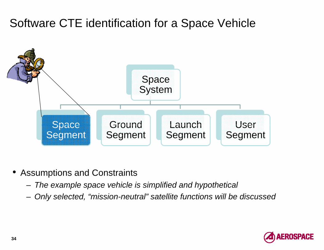
Software CTE identification for a Space Vehicle
Space Systemy
Space Ground Launch UserSpace Segment
Ground Segment
Launch Segment
User Segment
• Assumptions and Constraints– The example space vehicle is simplified and hypothetical– The example space vehicle is simplified and hypothetical– Only selected, “mission-neutral” satellite functions will be discussed
34

Architectural Documentation-related Definitions*
• Unified Modeling Language (UML®)– UML is a language for visualizing, specifying, constructing, and documenting
the artifacts of a software-intensive system• ContextContext
– Context includes all those things that on the outside interact with the system• Actor
– An Actor represents a role that a human, a hardware device, or another system plays with the objective system
– The Actor symbol in UML is as follows:y
• Deployment DiagramA di h i th d th t f th t ’ h d t l– A diagram showing the nodes that form the system’s hardware topology on which the system executes
35
* Source: [Booch 1999]® UML is Registered in the U.S. Patent and Trademark Office by The OMG, Inc.

Partial* Space Vehicle Flight Software Context Diagram
CrosslinkMisc telemetryNavigation
Control System
Attitude ControlSensors/Actuators
Misc. telemetry, timekeeping, payload
Messages
gNavigation Data
Space Vehicle
yOperator
Operator Commandsand Telemetry Data
CommunicationFlight Software Ground to Space
Vehicle
Communication
Timing ReferenceControl
Maintenance & Distribution of clock
Space Vehicle to Ground
Power ControlSensors/Controllers On‐board
RecoveryThermal ControlSensors/Controllers
RecoveryRecovery and Redundancy
36
* Only selected, “mission-neutral” satellite functions are shown

Sample Worksheet for Software CTE Identification
FUNCTIONAL AREA COMMENTS ARE THERE ANY SOFTWARE CTE CANDIDATES?*
Attitude Control • Reading attitude sensors • Control attitude actuators
Most likely no
Communication (External) • Space Vehicle to Ground • Ground to Space Vehicle
Maybe(Depends on mission)p ( p )
Communication (Internal) • Interfacing with other payloads Most likely no Crosslink Processing • Miscellaneous telemetry,
timekeeping, and payload messages across satellites
Most likely no
Data Base Management Most likely noData Base Management Most likely noPayload Bus Controller Most likely no Diagnostics and Maintenance • Recovery management
• Redundancy processing Most likely no
Electrical Power Subsystem Control • Sensors • Controllers
Most likely no • Controllers
Keeping Time (Clock) • Maintaining time information Most likely no Navigation/Management of the Space Vehicle (SV) • Reading telemetry data
• Commanding the SV Most likely no
Thermal Control • Sensors Most likely no • Controllers
etc.
37
* Note that in case of any potential candidates the 6 CTE identification questions would have to be answered for final classification

UML Deployment Diagram for the Space Vehicle
<processor>P l d B
<processor>SV S b t
<processor>SV C
<processor>Oth
<processor>OthPayload Bus
ControllerSV Subsystem
ControlSV Comm
ControlOther
PayloadsOther
Payloads
Bus
• Payload Bus Controller is usually a COTS solution• Other payloads could be miscellaneous communications imagery infra
Bus
• Other payloads could be miscellaneous communications, imagery, infra-red radar, etc. processing, depending on the actual mission
38

TRA-Oriented, Customized Deployment Diagram*
No Human
Interface
Software Applications for SV Subsystem Control
- Command processing- Electrical Power Subsystem processing- Navigation and Control data processing-Telemetry data collection and processing
No Human
Interface
Software Applications for SV Communications
- Crosslink processing- Database management- Payload to Payload communication- SV to Ground Communication
HW IN HW OUT
SW Drivers
Tools
CommunicationsInfrastructure
Real-time Operating System SW Drivers
y p g-Thermal data processing- etc.
SW Drivers
Tools
CommunicationsInfrastructure
Real-time Operating System SW Drivers
- Timekeeping processing- etc.
HW IN- Attitude sensors- Thermal sensors- Power sensors
Memory Processor
HW OUT- Attitude actuators- Thermal control- Power control
CommunicationsHW
(Bus)
Bus
HW IN- Crosslink
- ClockMemory Processor
HW OUT- CrosslinkCommunications
HW(Bus)
• Conclusions:
Bus
− Apparently no need for “extreme” new or novel solutions− For sake of simplicity we assume that no reuse or COTS are planned− We still need to examine dependency and tools issues
39
* Note that distributing functionality across processors is an architecting step. The deployed functionality on the processor does not always neatly match the subsystem name.

Detour: Dealing with Radiation in Space Hardware
• Why is electromagnetic interference a problem?– In presence of ionizing radiation a single charged particle can knock
thousands of electrons loose• Major radiation damage sources in spacej g p
– Solar particle events– Van Allen radiation belts– Cosmic rays, etc.Cosmic rays, etc.
• Selected effects of radiation on electronics– Rearrangement of the atoms, creating lasting damage
Transient ionization effect or latchup– Transient ionization effect or latchup• During a single-event latchup, heavy ions or high-energy protons are
passing through the inner-transistors of the circuit, causing a “short”R di ti h d i (“ d h d”)• Radiation hardening (“rad-hard”)
– It is a method of designing and testing electronic components to make them resistant to electromagnetic radiation damage
40

Radiation Hardening
• Selected radiation hardening approaches*– Shielding– Shielding
• Involves complete shielding of assemblies and subsystems– Radiation-Hardening-by-Process (RHBP)
• Thi i th “ l i ” h t d h d• This is the “classic” approach to rad-hard • “Process” refers to the semiconductor fabrication process
– Chips made on special, insulating substrates like silicon oxide or sapphire
– Choice of substrate with wide band gap– Radiation-Hardening-by-Design (RHBD)
• The radiation mitigation techniques are implemented in layout or in the chip architecture and not in the fabrication process
– Augmenting reliability techniquesg g y q• Using redundant elements on circuit- and/or system level• Applying a watchdog timer to perform a hard reset if needed
41
* Reference: [Barnaby 2004]

Software Technology Readiness Implications
• Shielding is the only solution without software implications– However, it is bulky and heavy
• Remember, excess weight carries a special penalty in space designs• In case of all other solutions exercise caution
– Many vendors developed rad-hard processors that are based on (and claimed to be equivalent with) various, commercial processors, such as the IBM PowerPC. However, they have to be evaluated on a case-by-case basisIBM PowerPC. However, they have to be evaluated on a case by case basis• For real-time applications the development environment, including the
used compiler, has to be validated on the same rad-hard platform• With respect to the objective system the main concern is the preservation• With respect to the objective system, the main concern is the preservation
of real-time characteristics when the software, at the last phase of the development process, is moved from a commercial, developer platform to
d h d l tf (“O ti l lik ” S ft E i t)a rad-hard platform (“Operational-like” Software Environment)• Conclusion
– The understanding of hardware technology options and their maturity is essential for a successful software TRA
42

The Dependency of Software TRLs on Hardware TRLs
PL(Programming
Language)
DE(De elopment(Development Environment)
OS(Real-time Operating
System )
HW(Processor
Board)
TRL(PL) ≤ TRL(DE) ≤ TRL(OS) ≤ TRL(HW)
43
The equation above saves the effort of fully understanding the details of the particular layers ☺

Ground System Case StudyGround System Case Study
Is Service-Oriented Architecture (SOA) a Critical Technology Element?
“…And there is nothing new under the sun.Is there anything of which it may be said, ’See, this is new’?It has already been in ancient times before us.”y~~~ Ecclesiastes 1:9-10

SOA as a CTE in a Ground System
Space Systemy
Space Ground Launch UserSpace Segment
Ground Segment
Launch Segment
User Segment
• SOA as a CTE?– Google produced 40 million (!) hits in 0.2 sec for “SOA”. Even if we discount
hits on the Society of Actuaries and such, it is very impressive. Wouldn’t it y , y pprove that it is a mature technology?
– No. Using SOA is a risky proposition and extreme caution is needed. SOA belongs to the category where concepts and new code, reuse, and COTSbelongs to the category where concepts and new code, reuse, and COTS dimensions all might have to be evaluated.
45

Detour: What is a Service-Oriented Architecture (SOA)?
• Architecture*“A hit t i th f d t l i ti f t b di d i it– “Architecture is the fundamental organization of a system embodied in its components, their relationships to each other and to the environment, and the principles guiding its design and evolution.”
• Service Oriented Architecture**• Service-Oriented Architecture**– “A Service-Oriented Architecture takes advantage of networking capabilities
to integrate applications in a way that is independent of architecture, programming language development platform and vendor Through a set ofprogramming language, development platform and vendor. Through a set of standard interfaces, services are made available to any consumer willing to follow the rules for interface and consumption.”
• Selected generic SOA services• Selected, generic SOA services– Messaging, mediation/translation between data structures and protocols,
Data Base Management System (DBMS,) high-speed networking, collaboration Information Assurance/Security etccollaboration, Information Assurance/Security, etc.
• Question to ponder– What do you think the benefits of using such an architectural style are?
46
* Source: [ISO/IEC 2007]** Source: [Minkiewicz 2007]

The Road to SOA for Space
• SOA is a promising approach to implement Operational Responsive Space (ORS) and Joint Warfighting Space (JWS)Space (ORS) and Joint Warfighting Space (JWS)
• Operational Responsive Space – ORS is characterized by an incremental approach from prototyping to
production on the basis of highly modularized capabilitiesproduction, on the basis of highly modularized capabilities – According to the early ORS ideas, the key to achieving these objectives is
space system bus* standardization• Note that the term “bus” in ORS equally relates to all segments of a spaceNote that the term bus in ORS equally relates to all segments of a space
system, not only to the space vehicle. • Joint Warfighting Space [Schuler 2005]
– The JWS initiative seeks to make space an organic part of joint task forces inThe JWS initiative seeks to make space an organic part of joint task forces in theater
– ORS is an enabler of JWS• Question to ponderQuestion to ponder
– What do you think the connection is between ORS and the earlier mentioned NCW doctrine?
* ORS i i ll i t d d b th d f t Offi f F T f ti
47
* ORS was originally introduced by the now defunct Office of Force Transformation (OFT) DOD entity. Here we only refer to the generic aspects of the earlier OFT proposal.

Selected SOA Services for a Ground System
• Sample Ground functionality that could be implemented via services*C d P i– Command Processing• Commands to space vehicles• Commands to antennae systems
Orbital Data Processing– Orbital Data Processing– Critical alarms– Mission Planning
Real time Telemetry Processing– Real-time Telemetry Processing– Processing/providing data on external interfaces
• Other ground stations• External clients of ground station servicesExternal clients of ground station services
– Situational awareness– Etc.
• Of course a SOA Framework would be needed as wellOf course a SOA Framework would be needed as well– E.g., to implement the registry that facilitates the seamless integration,
upgrade, discovery and invocation of services
48
* Caveat: SOA does not always make sense for implementing all Ground System functionality

SOA Components in a Ground System
Software Applications Human Interface
…Tools
…
CommunicationsOperating S t & Services Infrastructure Middle-
Application Programming Interfaces (APIs)
Memory&
St D iProcessor
(Computing Node)
Infrastructure
Communications HW(Bus)
System & Libraries (SOA Framework)
Middleware
Storage Devices (Computing Node) (Bus)
Legend: Potential SOA Component
49
Legend: Potential SOA ComponentNote that this GS example does not have HW input/output elements other than the bus

CTE Identification Questions Revisited
1) Does the technology have a significant impact on an operational requirement, cost, or schedule?
2) Does this technology pose a major development or demonstration risk?risk?
3) Is the technology new or novel?4) Has the technology been modified from prior successful use?5) Has the software technology been repackaged such that a new
relevant environment is applicable?6) Is the technology expected to operate in an environment and/or6) Is the technology expected to operate in an environment and/or
achieve a performance beyond its original design intention or demonstrated capability?
A technology element is critical if the answer to the first question and to any of the remaining questions is “yes”
50

CTE Identification Question 1
(1) Does the technology have a significant impact on an operational requirement, cost, or schedule?• Regarding operational requirements the answer is definitely YES, due to the Net-Ready KPP and the earlier mentioned OUSD SOA directive implicationsdirective implications • Also, regarding Cost and Schedule, service-orientation provides numerous enablers for improvement
Th f k d b ildi bl k b i d COTS– The framework and core building blocks can be acquired as COTS– Services allow substantial reuse– A properly designed SOA framework enables the automatic discovery of
fi i d ft i ti t th i i iti dfine-grained software services, negotiates their acquisition, and composes, binds, executes, and unbinds them
– The use of SOA speeds-up the incremental delivery of new capabilities in the system evolution contextin the system evolution context
– Through loose coupling and tight interface standards, consumers of services need only know how to interact with a service, and there is no need to understand deeper detailsneed to understand deeper details
51

CTE Identification Questions 2-4
(2) Does this technology pose a major development or demonstration(2) Does this technology pose a major development or demonstration risk?• YES. SOA is very pervasive, the associated components show up in many different parts of the overall systemin many different parts of the overall system
(3) Is the technology new or novel?• NO. Do you remember Distributed Object Architecture (DOA,)NO. Do you remember Distributed Object Architecture (DOA,) Common Object Model (COM,) Object Request Broker (ORB,) Common Object Requerst Broker Architectrure (CORBA,) etc.?
(4) Has the technology been modified from prior successful use?(4) Has the technology been modified from prior successful use?• It depends. However, most likely the answer is NO, because the SOA COTS elements would not be modified
52

CTE Identification Questions 5-6
(5) Has the technology been repackaged such that a new relevant environment is applicable?environment is applicable?• Maybe. “Repackaging” is a broad term and involves considerations for both the hardware and systems software platforms of the SOA services. This question is particularly critical when services are independently adopted for the objective system
(6) Is the technology expected to operate in an environment and/or(6) Is the technology expected to operate in an environment and/or achieve a performance beyond its original design intention or demonstrated capability?
YES O f th i ith SOA i l t ti i th• YES. One of the main concerns with SOA implementations is the overhead associated with service invocation/execution and its impact on performance and Quality of Service (QoS). It is very unlikely that the structure of the objective system would be identical to a prior system already in use; hence these factors should be verified in advance
53

Evaluation of Answers
1) Does the technology have a significant impact on an operational1) Does the technology have a significant impact on an operational requirement, cost, or schedule? YES
2) Does this technology pose a major development or demonstration risk? YES
3) Is the technology new or novel? NO4) Has the technology been modified from prior successful use? NO4) Has the technology been modified from prior successful use? NO5) Has the software technology been repackaged such that a new
relevant environment is applicable? Maybe6) Is the technology expected to operate in an environment and/or
achieve a performance beyond its original design intention or demonstrated capability? YESdemonstrated capability? YES
Conclusion: Due to YES answers to questions 1, 2, and 6, SOA is a CTE
54
Reminder: A technology element is critical if the answer to the first question and to any of the remaining questions is “yes”

More SOA Specifics
• The 6 questions need to be carefully applied and special attention to be paid to the following specifics:paid to the following specifics:
– Platform/Relevant Environment compatibility for COTS SOA elements• Note that different services might come from different sources
– Inter-component Compatibility of acquired COTS SOA elements• See reason given at the prior issue
– Execution performance considerations and scaling of servicesExecution performance considerations and scaling of services• SOA involves a lot of overhead; as it was mentioned earlier, the impact
needs to be carefully assessed in advanceSOA interface adequacy for new services– SOA interface adequacy for new services• Service uniformity is achieved via standard interfaces; however, beyond
the core functionality, the inherent throughput, data capacity, error tolerance testability etc might not be enough for the new servicetolerance, testability, etc. might not be enough for the new service.
– Feasibility and effort needed to interface reused and legacy software• Due to the fact that most likely only selected functionality would be
provided as a “service”
55

COTS/Reuse Evaluation Revisited*
• The application of COTS/Reused Software is a very attractive but at the same time very risky approach to software development
– Consequently, we need clarity on what COTS/Reuse Attributes are in-scope for a TRA and what inquiries belong to the “routine”, programmatic risk q g , p gmanagement area
In-scope for Trades and Risk Reduction− Documentation quality
• In-scope for TRA− Accuracy, correctness Documentation quality
− Ease of Use− Flexibility− Installation/Upgrade Ease
Accuracy, correctness− Availability− Robustness− Security pg
− Portability− Price− Vendor support and maturity
y− Product performance− Testability− Version compatibility
* Note that the assessment of evaluation glue code writing and integration cost(effort and
− Training− Vendor concessions
− Inter-component Compatibility− Functionality
56
Note that the assessment of evaluation, glue code writing, and integration cost(effort and schedule) is also out of scope for a TRA while it is a very critical planning activity.

Challenging Topics(What they Don’t Teach at the Defense Acquisition University…)( y q y )
“Technological change is like an“Technological change is like an axe in the hands of a pathological
criminal.”Alb t Ei t i~~~ Albert Einstein

“Challenging” is a Euphemism for Controversial…
• Sources of controversy– Incorrect or ambiguous government guidance– Lack of consensus amongst the practitioners– Mismanaged expectations
• Issues to be discussedThe consequences of rolling up TRLs– The consequences of rolling-up TRLs• The need to roll-up TRLs many times manifests itself as a call for
providing a single system maturity index– A sub-issue that needs to be addressed is the attempt for algebraic p g
manipulation of an ordinal measurement scale– Putting too much faith into the predictive ability of TRLs
• The underlying issue is to understand that technology development h ld b i d i ti d h it i hi hlshould be viewed as an innovation process and as such it is highly
unpredictable– TRA vs. Risk Management
• We will look at a particular example programming language selection forWe will look at a particular example, programming language selection for high assurance software, where they are in conflict
– The confusion between Technology Maturity and Software Maturity• We will look at the reasons, i.e., confusing definitions and lack of g
understanding of the systems and software engineering life cycle processes
58

Rolling-up TRLs
• Rolled-up TRLs are supposed to provide one single maturity number for a system or a SOS
– The idea equally relates to a single system with multiple CTEs or a SOS with dominant CTEs (or rolled-up TRLs…) assigned to the participating systems( p ) g p p g y
• Question: What would be your recommendation for a roll-up rule?a) Use the lowest TRL
TRL MIN (TRL TRL TRL )TRLSYS = MIN (TRL1, TRL2, …, TRLn)b) Compute the arithmetic average of TRLs
TRLTRLTRLTRLSYS = n
TRL...TRLTRL n21 +++
c) I have another method to do the roll-upd) I don’t recommend rolling-up TRLs
59

Rolling-up TRLs: My Answers in the order of preference
• (d) Don’t roll-up TRLs– No real need for roll-up
• If CTE selection has been correctly carried out then we should not have too many technology elements to deal with
– It is beneficial to keep the maturity evolution of CTEs separately visible• However, in case of dependency they need to be collectively re-evaluated
• (a) Use the lowest TRL• (a) Use the lowest TRL– This approach is based on well-known reliability principles
• If all selected CTEs are indeed critical* then the weakest link should be used to describe the maturity of the overall system or SOS
• (b) Arithmetic average of TRLs– Not acceptable. One mustn’t do arithmetic on ordinal scales under anyNot acceptable. One mustn t do arithmetic on ordinal scales under any
circumstances• (c) Do you have any suggestions?
60
* Remember, the 6 CTE identification questions should narrow down the candidate CTE list

TRL as an Ordinal Scale
• Unlike in “classic” risk prioritization schemes, a single, 1-9 integer is assigned to every maturity level
TRL 9integer is assigned to every maturity level
– For any CTE the impact of not moving-up from any level to the next within the program’s cost and schedule constraints is the loss of the total program
TRL 8
TRL 7 the loss of the total program• In conventional risk management
– Risks are characterized with their likelihood and their impact
TRL 7
TRL 6TRL 6
– Risk burn-down plans can be put in place to reduce or eliminate risks
• What do the TRLs represent?
TRL 5TRL 5
TRL 4 What do the TRLs represent?– TRLs represent a certain level of growing confidence that the
technology will perform as intended. However, we cannot quantify this confidence beyond the “warm feeling” what an
TRL 3
quantify this confidence beyond the warm feeling what an ordinal scale could provide• We don’t know the likelihood of success at any levels• W t il ti t th t ith
TRL 2
TRL 1• We cannot easily estimate the costs either
– Details to follow on the next few slides61

A Creative Problem Solving Profile for Innovation*
• Despite the diagram’s neat symmetry in reality the steps insymmetry, in reality the steps in the slices have different
– DurationsA ti it t– Activity types
– Levels of complexity– Levels of difficultyy
• In fact, according to Basadur, the profile not only changes by problem type but it is alsoproblem type, but it is also different individual by individual
• Phase 4 is the most volatile
62
* Source: [Basadur 2001]

Technology Development as an Innovation Process
TRL 9
TRL 8
TRL 7 E.g., moving from TRL 1 TRL 2 requires the TRL 7
TRL 6TRL 6
g g qapplication of the 8-step problem solving process to• Studying and documenting competing technologies• Creating an experimental environment
TRL 5TRL 5
TRL 4
g p• Determining what research methods should be used• Determining and acquiring data needed for validation• Finally, documenting how the concept will be applied
TRL 3
TRL 2
TRL 1
63
Note the “red slices” for every level where the need for individual creativity is particularly critical

… but Wouldn’t Phase 4 Volatility Gradually Decrease?
• One might intuitively think that when a CTE matures, the uncertainty associated with the needed innovation gradually decreases and estimation predictability increases
• HoweverHowever– This idea is based on the idealistic assumption that all CTEs are totally
independent. In reality, mainly at and above TRL 6, we have to worry about potential interference from other CTEs or in some cases even from otherpotential interference from other CTEs or in some cases even from other, non-critical system elements • This potential for interference is gradually increasing as the expanding
structural context dimension of the rating scheme showsstructural context dimension of the rating scheme shows• The need for creative, innovative thinking is not decreasing
– In fact, CTEs often have to be recursively re-evaluated or even fundamentally changed as their maturity evaluation and the overall system implementation progress
64

And Finally, an Expert’s Voice …
• Richard Feynman* was once asked how many process steps he used during problem solving. After some thinking, he said that his “secret” process formula constituted the following three steps:
1) Write down the problem1) Write down the problem 2) Think real hard 3) Write down the solution
* Richard Feynman (1918-1988); professor and researcher; one of the Richard Feynman (1918 1988); professor and researcher; one of the most famed physicist of the world. Besides his work on the atomic bomb at the Manhattan Project, he became also known as a key member of the panel that investigated the Space Shuttle Challenger disaster. The i l d d i t i f hi ld t ID f L Al
65
included picture is a copy of his old government ID from Los Alamos (Photograph reprinted courtesy of the United States Government.)

TRA and Risk Management Revisited
• We made an effort to neatly separate TRA and Risk Management– However, there are various situations for interplay, synergy, and even
conflict• Example for synergistic relationshipExample for synergistic relationship
– There are numerous items that are not intentionally in-scope for a TRA, but the IRT might get insight into during attendance of the contractors’ design reviews studying research documents etcreviews, studying research documents, etc.
– It is the IRT members’ duty to go beyond the core reporting on critical technologies and provide risk warnings to program management on any technology related risk that has been discovered during a TRAtechnology-related risk that has been discovered during a TRA
• Example for interplay– In case of COTS, TRA is viewed as an early screening activity to narrow
down the list of COTS options for trade studies and risk reduction activities • Example for conflict
– Selection of a programming language/compiler for flight software (details toSelection of a programming language/compiler for flight software (details to follow.)
66

Ada or C++ For Developing High Assurance Software?
Level of Protection Within the Languages*
Criteria C++ Ada 95Wild Jumps Some FewO it S FOverwrites Some Few
Semantics Some Good
Model of Maths None Good
Operational Arithmetic None Good
Data Typing Some GoodException Handling Some Good
Safe Subsets None Good
Exhaustion of Memory Some RareySeparate Compilation Some Good
* The issue is that there is a higher probability of violating good programming practices with
67
* The issue is that there is a higher probability of violating good programming practices with C++ than with a more declarative language like Ada 95. For criteria details please see next slide.

Criteria for Ada/C++ Comparison
•Wild Jumps– The program cannot jump to an arbitrary memory location
O it• Overwrites– The program cannot overwrite an arbitrary memory location
• Semantics– The compiler supports static code analysis– The compiler supports static code analysis
• “Model of Maths”– A rigorous model for floating-point and integer arithmetic
• Operational Arithmeticp– Run-time checking to ensure adherence to “model of maths”
• Data Typing– Typing model is strong enough for static checking and run-time checking
• Exception Handling• Exception Handling– Mechanisms to facilitate recovery from run-time faults are provided
• Safe Subsets– A language subset exists that increases the safety of the languageA language subset exists that increases the safety of the language
• Exhaustion of Memory– A mechanism exists to ensure that the program does not run out of memory
• Separate compilation– Type checking is provided across all parts of the development environment
68

Analysis: Technology vs. Programmatic Risks with Ada
• Even though it seems that Ada is superior for high-assurance, embedded system development, there are several reasons for the program manager to vote against Ada (Factors not supposed to be considered during a TRA):g )
– Ada programming skills are becoming scarce• Universities shun Ada; they believe that there is no market for Ada skills• There is a disdain toward Ada amongst programmers that is partially a
backlash due to the earlier DOD Ada mandate• Ada programmers have difficulty in getting jobs outside of DoD
– The available selection of development environments and tools for Ada is becoming narrower and more expensive
• We need to balance between what the technology buys vs other factors• We need to balance between what the technology buys vs. other factors that could be more relevant in assessing programmatic risks
– The programmatic risks associated with adopting Ada may be higher than with adopting C++ even though Ada clearly poses a lower technology risk
69

Software Technology Maturity is not Software Maturity
• Software Technology Maturity definition revisited– A measure of degree to which proposed concepts, processes, methods,
algorithms, or tools, whose primary purpose is the development, operation, understanding, and maintenance of software, meet program objectives
• Software Maturity (Software Product Maturity or Technical Maturity) h t i ti d ti ll diff tcharacteristics are drastically different– The form of software evolves rather than being replaced by artifacts of
different forms (note the breadboards brassboards manufactured items t h i i f h d )metamorphosis in case of hardware)
• In most cases – unlike hardware – software is developed iteratively– All software artifacts continuously and concurrently evolve
S ft i t ti i diff t f h d i t ti– Software integration is different from hardware integration• Software integration is a continuous activity from the beginning of the
evolution of the objective systemOne does not “make” every component first and then “integrate”– One does not make” every component first and then integrate”
– Software Product Maturity is not an ever-increasing measure• Software can become “senile”
At some point in its life cycle the number of changes and bug fixes– At some point in its life cycle, the number of changes and bug-fixes can overwhelm the architecture and the software starts degrading
70

Software Technology Maturity is not Software Maturity (cont.)
• The distinction is not simply about mincing words– Technology maturity has an important gating role leading up to MS B,
while planning and monitoring software product evolution are essential after MS B.
• However, the current TRL definitions conflate these topics– TRLs 1-4 focus on traditional technology innovation-type activities– TRLs 5-7 focus on the fidelity of test/validation environments in relationTRLs 5 7 focus on the fidelity of test/validation environments in relation
to integration and Verification and Validation (V&V) type activities– TRLs 8-9 focus on productization and deployment activities
• I thi bl f h d l t f ?• Is this a problem for hardware elements of a program?– Maybe, but this tutorial is about software ☺
• Is this a problem for software elements of a program?p p g– Yes. TRLs 1-4 reflect indeed software technologies, but the shift to V&V
between TRL 4 and 5 is meant to be applied to a software productrather than a software technologyat e t a a so t a e tec o ogy
71

Concluding Thoughts
• Technology Readiness Assessment, a critical tool in Defense Acquisition, helps us to prevent the incorporation of immature technologies during system design
• Modern weapon systems are software-intensive systems;Modern weapon systems are software intensive systems; consequently, the early evaluation of software technologies is essential
• Software Technology Readiness Assessments are carried out by ft i li t Hsoftware specialists. However
– An understanding of the maturity of all related, hardware technologies is necessary
– During Technology Readiness Assessments a careful coordination amongst the technical area specialists is also a must
72

I am Sorry if You are Still Confused …
TRA
NCI
TRA
I am sure I have failed to anticipate or answer all of your questions I am sorry ifI am sure I have failed to anticipate or answer all of your questions. I am sorry if it seems that the answers I provided only served to raise a new set of questions. In some ways you might feel that you (and I...) are still as confused as ever, but I do believe that now we are confused on a much higher level and about moredo believe that now we are confused on a much higher level and about more important things…Thank you again for attending the tutorial!
73

AcronymsACQ Acquisition API Application Programming Interface
APO Acquisition Program Office ASIC Application Specific Integration Circuit
NCI Network Centric Infrastructure NCO Network Centric Operations NCW Network Centric Warfare NSS National Security Space
AT&L Acquisition, Technology, & Logistics CASE Computer-Assisted Software Engineering
CM Configuration Management CMMI Capability Maturity Model Integration COTS C i l Off th Sh lf
NSSAP National Security Space Acquisition Policy OFT Office of Force Transformation
OMG Object Management Group ORS Operational Responsive Space
OS O ti S tCOTS Commercial Off-the-Shelf CTE Critical Technology Element
DAPA Defense Acquisition Performance Assessment DBMS Data Base Management System
DDR&E Director of Defense Research & Engineering
OS Operating SystemOT&E Operational Test & Evaluation OUSD Office of the Under Secretary of Defense
PL Programming Language PSP Personal Software ProcessDDR&E ecto o e e se esea c & g ee g
DE Development Environment DOD Department of Defense DAB Defense Acquisition Board
FPGA Field-Programmable Gate Array
PSP e so a So t a e ocessR&D Research & Development
RHBD Radiation Hardening by Design RHBP Radiation Hardening by Process
RPC Remote Procedure Call GOTS Government Off-the-Shelf
GUI Graphical User Interface HW Hardware IEC International Electrotechnical Commission IRT Independent Review Team
SAF/AQ Secretary of the Air Force/Acquisition SEAM Systems Engineering Assessment Model
SMC Space and Missile Systems Center SOA Service Oriented Architecture STD StandardIRT Independent Review Team
ISO International Standards Organization JWS Joint War-fighting Space KDP Key Decision Point MDD Model Driven Development
STD StandardSW Software
TRA Technology Readiness Assessment TRL Technology Readiness Level UML Unified Modeling Language
74
pMIL Military
MOIE Mission-Oriented Investigation and Experimentation
g g gUSC United States Code V&V Verification & Validation

ReferencesBarnaby 2004 Barnaby, H. J., Will Radiation-Hardening-by-Design (RHBD) Work?, IEEE Nuclear &
Plasma Sciences Society News, September 2004
Basadur 2001 Basadur, M., The Power of Innovation: How to Make Innovation a Way of Life and How to Put Creative Solutions to Work, Applied Creativity Press, Toronto Canada 2001, pp y ,
Booch 1999 Booch, G., et al, The Unified Modeling Language User Guide, Addison-Wesley 1999
DAPA 2006 Defense Acquisition Performance Assessment Report, March 2006
DOD 2009 DOD Technology Readiness Assessment (TRA) Deskbook, July 2009
Foreman 1997 Foreman, J., et al, Software Technology Review, CMU/SEI draft, June 1997
ISO/IEC 2007 Recommended Practice for Architectural Description of Software-Intensive Systems, ISO/IEC 42010:2007
Minkiewicz 2007 Minkiewicz, A., The Cost and Business Impact of SOA – Is it Right for You, A Price Systems Thought Leadership Article on the Price Systems websiteSystems Thought Leadership Article on the Price Systems website
OUSD 2008 OUSD(AT&L) Memorandum for Service Acquisition Executives on the Implementation of Service Oriented Architecture (SOA) within DOD Acquisition Community, 25 July 2008
Pew 2007 Pew, R., & Mavor, A., Human-System Integration in the System Development Process: A New Look National Academies Press 2007New Look, National Academies Press, 2007
Rocke 2006 Rocke, P., et al, Net Centric Enterprise Services (NCES) Applicability to Service Oriented Architectures within the DOD Satellite Command Community of Interest (COI), Ground System Architectures Workshop (GSAW) 2006
Schuler 2005 Schuler M A Joint Warfighting Space and C2 of Deployable Space Forces High
75
Schuler 2005 Schuler, M. A., Joint Warfighting Space and C2 of Deployable Space Forces, High Frontier – The Journal for Space & Missile Professionals, Vol. 1, No. 4, 2005
Backup Slides

Relevant Environment for Space
• Space Environment Attributes– Pressure (vacuum)– Temperature (deep space)– Gravity (microgravity on orbit)– Radiation– Electromagnetic Spectrum (star light, sunlight, x-ray, etc.)
• Launch Environment Attributes– Pressure (e.g., changing pressure, venting)– Temperature (e.g., payload fairing heating)– Gravity (acceleration,) Vibration, Structural Loads
• Designed Environment AttributesPh i l i t l i t ( lf t d h ti )– Physical internal environment (e.g., self generated heating)
– Software interaction with environment (processor throughput, memory capacity, bus bandwidth, etc.)H d I t f ( th l h t )– Hardware Interfaces (e.g., thermal shorts)
– Behavior of model or prototype in interfacing environment (dynamic behavior)
• Operational Environment Attributes• Operational Environment Attributes– Lifetime, Duty Cycles, Complex Dynamic Behavior
77

TRL 1-3 Evaluation Dimensions
TRL Basic TRL DEFINITIONS Artifacts Structural
Context SW
Environment Validation
Environment and Methods
Data Used for Validation
Configuration Management Documentation
1 Basic principles Research articles, n/a “Academic”, Basic n/a n/a Appropriate p pobserved and reported
,peer-reviewed white papers, point papers, early conceptual models
,experimental research
using analytical Methods
pp pand sufficient to demonstrate basic principles
2 Technology Analytic studies, n/a “Academic”, Applied Synthetic data n/a Appropriate gyconcept and/or application formulated
ypapers on competing technologies
experimentalpp
research using analytical Methods
yonly
pp pand sufficient to demonstrate application concept
3 Analytical and Analytical and n/a “Academic”, Active R&D Partially n/a Appropriate yexperimental critical function and/or characteristic proof of concept.
ysimulation models; Availability of appropriate COTS/GOTS or reusable software artifacts is explored.
experimental initiated via the use of models and simulation
yrepresentative data
pp pand sufficient to interpret analytical or experimental data; Full documentation is available on COTS/GOTS or reusable software under consideration.
These tables help to evaluate all factors associated with a TRL
78
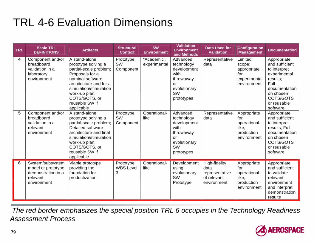
TRL 4-6 Evaluation Dimensions
TRL Basic TRL DEFINITIONS Artifacts Structural
Context SW
Environment Validation
Environment and Methods
Data Used for Validation
Configuration Management Documentation
4 Component and/or A stand-alone Prototype S
“Academic”, Advanced Representative Limited Appropriate ffbreadboard
validation in a laboratory environment
prototype solving a partial-scale problem;Proposals for a nominal software architecture and for a simulation/stimulation
k l
SW Component
experimental technology development with throwaway or evolutionary SW
data scope; appropriate for experimental environment
and sufficient to interpret experimental results; Full documentation
hwork-up plan; COTS/GOTS, or reusable SW if applicable
SW prototypes
on chosenCOTS/GOTS or reusable software
5 Component and/or breadboard
lid ti i
A stand-alone prototype solving a
ti l l bl
Prototype SW C t
Operational-like
Advanced technology d l t
Representative data
Appropriate for
ti l
Appropriate and sufficient t i t tvalidation in a
relevant environment
partial-scale problem;Detailed software architecture and final simulation/stimulation work-up plan; COTS/GOTS, or
bl SW if
Component development with throwaway or evolutionary SW
t t
operational-like, production environment
to interpret results; Full documentation on chosen COTS/GOTS or reusable
ftreusable SW if applicable
prototypes software
6 System/subsystem model or prototype demonstration in a relevant
Viable prototype providing the foundation for productization
Prototype WBS Level 3
Operational-like
Development using evolutionary SW
High-fidelity data representative of relevant
Appropriate for operational-like,
Appropriate and sufficient to validate relevant
The red border emphasizes the special position TRL 6 occupies in the Technology Readiness
environment Prototype environment production environment
environment and interpret demonstration results
The red border emphasizes the special position TRL 6 occupies in the Technology Readiness Assessment Process
79

TRL 7-8 Evaluation Dimensions
TRL Basic TRL DEFINITIONS Artifacts Structural
Context SW
Environment
Validation Environment and Methods
Data Used for Validation
Configuration Management Documentation
7 System prototype Productized WBS Level Actual SW End-to-end High-fidelity Appropriate Appropriate7 System prototype demonstration in an operational environment
Productized component
WBS Level 2
Actual SW Environment
End-to-end testing of Production SW using system simulator
High-fidelity data representative of relevant environment
Appropriate for the actual environment
Appropriate and sufficient to validate test results
8 A t l t P d ti d WBS L l A t l SW T ti f R l d t A i t A i t8 Actual system completed and qualified through test and demonstration
Productized component
WBS Level 1
Actual SW Environment
Testing of Production SW using OT&E
Real data Appropriate for the actual environment
Appropriate and sufficient to validate technology’s performance and operate
and maintain the product.
80

TRL 9 Evaluation Dimensions
TRL Basic TRL DEFINITIONS Artifacts Structural
Context SW
Environment
Validation Environment and Methods
Data Used for Validation
Configuration Management Documentation
9 A t l t P d ti d WBS L l A t l SW A t l R l d t C i t t A i t9 Actual system proven through successful mission operations
Productized component
WBS Level 1
Actual SW Environment
Actual Mission
Real data Consistent with the actual environment
Appropriate and sufficient to validate technology’s performance and operate
and maintain the product.
81

Use of Trademarks, Service Marks and Trade Names
Use of any trademarks in this material is not intended in any way to infringe on the rights of the trademark holder. All
trademarks, service marks, and trade names are the property p p yof their respective owners.
82