software manual drive solution designerdownload.lenze.com/td/drive solution...
TRANSCRIPT

L
Ä.[jôä
1358
7395
Drive SolutionDesigner
Engineering Tools
Manual EN

2 Lenze · Drive Solution Designer · Manual · DMS 4.9 EN · 10/2019 · TD23
_ _ _ _ _ _ _ _ _ _ _ _ _ _ _ _ _ _ _ _ _ _ _ _ _ _ _ _ _ _ _ _ _ _ _ _ _ _ _ _ _ _ _ _ _ _ _ _ _ _ _ _ _ _ _ _ _ _ _ _ _ _ _ _
1 Notes on usage _ _ _ _ _ _ _ _ _ _ _ _ _ _ _ _ _ _ _ _ _ _ _ _ _ _ _ _ _ _ _ _ _ _ _ _ _ _ _ _ _ _ _ _ _ 131.1 Licencing and contractual conditions _ _ _ _ _ _ _ _ _ _ _ _ _ _ _ _ _ _ _ _ _ _ _ _ _ _ _ _ _ _ _ _ _ _ 131.2 Terms and conditions _ _ _ _ _ _ _ _ _ _ _ _ _ _ _ _ _ _ _ _ _ _ _ _ _ _ _ _ _ _ _ _ _ _ _ _ _ _ _ _ _ _ 131.3 Important information on the program _ _ _ _ _ _ _ _ _ _ _ _ _ _ _ _ _ _ _ _ _ _ _ _ _ _ _ _ _ _ _ _ 13
2 About this documentation _ _ _ _ _ _ _ _ _ _ _ _ _ _ _ _ _ _ _ _ _ _ _ _ _ _ _ _ _ _ _ _ _ _ _ _ _ _ _ 162.1 Conventions used _ _ _ _ _ _ _ _ _ _ _ _ _ _ _ _ _ _ _ _ _ _ _ _ _ _ _ _ _ _ _ _ _ _ _ _ _ _ _ _ _ _ _ _ 172.2 Definition of the notes used _ _ _ _ _ _ _ _ _ _ _ _ _ _ _ _ _ _ _ _ _ _ _ _ _ _ _ _ _ _ _ _ _ _ _ _ _ _ 18
3 User interface _ _ _ _ _ _ _ _ _ _ _ _ _ _ _ _ _ _ _ _ _ _ _ _ _ _ _ _ _ _ _ _ _ _ _ _ _ _ _ _ _ _ _ _ _ _ 193.1 Control and function elements _ _ _ _ _ _ _ _ _ _ _ _ _ _ _ _ _ _ _ _ _ _ _ _ _ _ _ _ _ _ _ _ _ _ _ _ _ 19
3.1.1 Menu bar _ _ _ _ _ _ _ _ _ _ _ _ _ _ _ _ _ _ _ _ _ _ _ _ _ _ _ _ _ _ _ _ _ _ _ _ _ _ _ _ _ _ _ _ 203.1.2 Toolbar _ _ _ _ _ _ _ _ _ _ _ _ _ _ _ _ _ _ _ _ _ _ _ _ _ _ _ _ _ _ _ _ _ _ _ _ _ _ _ _ _ _ _ _ _ 253.1.3 Drawing _ _ _ _ _ _ _ _ _ _ _ _ _ _ _ _ _ _ _ _ _ _ _ _ _ _ _ _ _ _ _ _ _ _ _ _ _ _ _ _ _ _ _ _ 283.1.4 Navigation tree and result tree _ _ _ _ _ _ _ _ _ _ _ _ _ _ _ _ _ _ _ _ _ _ _ _ _ _ _ _ _ _ _ _ 333.1.5 Input area _ _ _ _ _ _ _ _ _ _ _ _ _ _ _ _ _ _ _ _ _ _ _ _ _ _ _ _ _ _ _ _ _ _ _ _ _ _ _ _ _ _ _ _ 343.1.6 Notes _ _ _ _ _ _ _ _ _ _ _ _ _ _ _ _ _ _ _ _ _ _ _ _ _ _ _ _ _ _ _ _ _ _ _ _ _ _ _ _ _ _ _ _ _ _ 37
3.2 Shortcuts _ _ _ _ _ _ _ _ _ _ _ _ _ _ _ _ _ _ _ _ _ _ _ _ _ _ _ _ _ _ _ _ _ _ _ _ _ _ _ _ _ _ _ _ _ _ _ _ _ 393.3 Closing the program _ _ _ _ _ _ _ _ _ _ _ _ _ _ _ _ _ _ _ _ _ _ _ _ _ _ _ _ _ _ _ _ _ _ _ _ _ _ _ _ _ _ _ 40
4 Setting up the DSD workplace _ _ _ _ _ _ _ _ _ _ _ _ _ _ _ _ _ _ _ _ _ _ _ _ _ _ _ _ _ _ _ _ _ _ _ _ _ 414.1 Settings during installation _ _ _ _ _ _ _ _ _ _ _ _ _ _ _ _ _ _ _ _ _ _ _ _ _ _ _ _ _ _ _ _ _ _ _ _ _ _ _ 414.2 Language _ _ _ _ _ _ _ _ _ _ _ _ _ _ _ _ _ _ _ _ _ _ _ _ _ _ _ _ _ _ _ _ _ _ _ _ _ _ _ _ _ _ _ _ _ _ _ _ _ 414.3 Settings _ _ _ _ _ _ _ _ _ _ _ _ _ _ _ _ _ _ _ _ _ _ _ _ _ _ _ _ _ _ _ _ _ _ _ _ _ _ _ _ _ _ _ _ _ _ _ _ _ _ 42
4.3.1 "General" register _ _ _ _ _ _ _ _ _ _ _ _ _ _ _ _ _ _ _ _ _ _ _ _ _ _ _ _ _ _ _ _ _ _ _ _ _ _ _ 424.3.2 "Network connections" register _ _ _ _ _ _ _ _ _ _ _ _ _ _ _ _ _ _ _ _ _ _ _ _ _ _ _ _ _ _ _ _ 434.3.3 "Help" tab _ _ _ _ _ _ _ _ _ _ _ _ _ _ _ _ _ _ _ _ _ _ _ _ _ _ _ _ _ _ _ _ _ _ _ _ _ _ _ _ _ _ _ _ 434.3.4 "Motion" register _ _ _ _ _ _ _ _ _ _ _ _ _ _ _ _ _ _ _ _ _ _ _ _ _ _ _ _ _ _ _ _ _ _ _ _ _ _ _ _ 434.3.5 "Units" tab _ _ _ _ _ _ _ _ _ _ _ _ _ _ _ _ _ _ _ _ _ _ _ _ _ _ _ _ _ _ _ _ _ _ _ _ _ _ _ _ _ _ _ 444.3.6 "Protocol" tab _ _ _ _ _ _ _ _ _ _ _ _ _ _ _ _ _ _ _ _ _ _ _ _ _ _ _ _ _ _ _ _ _ _ _ _ _ _ _ _ _ _ 444.3.7 "Customer data" tab _ _ _ _ _ _ _ _ _ _ _ _ _ _ _ _ _ _ _ _ _ _ _ _ _ _ _ _ _ _ _ _ _ _ _ _ _ _ 454.3.8 "User data" tab _ _ _ _ _ _ _ _ _ _ _ _ _ _ _ _ _ _ _ _ _ _ _ _ _ _ _ _ _ _ _ _ _ _ _ _ _ _ _ _ _ 45
4.4 Communication with the Lenze DSD server _ _ _ _ _ _ _ _ _ _ _ _ _ _ _ _ _ _ _ _ _ _ _ _ _ _ _ _ _ _ 464.4.1 Messages _ _ _ _ _ _ _ _ _ _ _ _ _ _ _ _ _ _ _ _ _ _ _ _ _ _ _ _ _ _ _ _ _ _ _ _ _ _ _ _ _ _ _ _ 464.4.2 Software updates _ _ _ _ _ _ _ _ _ _ _ _ _ _ _ _ _ _ _ _ _ _ _ _ _ _ _ _ _ _ _ _ _ _ _ _ _ _ _ 474.4.3 Assistance in dealing with problems _ _ _ _ _ _ _ _ _ _ _ _ _ _ _ _ _ _ _ _ _ _ _ _ _ _ _ _ _ 47
5 Managing projects _ _ _ _ _ _ _ _ _ _ _ _ _ _ _ _ _ _ _ _ _ _ _ _ _ _ _ _ _ _ _ _ _ _ _ _ _ _ _ _ _ _ _ _ 485.1 Create new project _ _ _ _ _ _ _ _ _ _ _ _ _ _ _ _ _ _ _ _ _ _ _ _ _ _ _ _ _ _ _ _ _ _ _ _ _ _ _ _ _ _ _ 485.2 Project information _ _ _ _ _ _ _ _ _ _ _ _ _ _ _ _ _ _ _ _ _ _ _ _ _ _ _ _ _ _ _ _ _ _ _ _ _ _ _ _ _ _ _ 495.3 Open project _ _ _ _ _ _ _ _ _ _ _ _ _ _ _ _ _ _ _ _ _ _ _ _ _ _ _ _ _ _ _ _ _ _ _ _ _ _ _ _ _ _ _ _ _ _ _ 50
5.3.1 Import project _ _ _ _ _ _ _ _ _ _ _ _ _ _ _ _ _ _ _ _ _ _ _ _ _ _ _ _ _ _ _ _ _ _ _ _ _ _ _ _ _ 515.3.2 Open the project in the ProjectViewer _ _ _ _ _ _ _ _ _ _ _ _ _ _ _ _ _ _ _ _ _ _ _ _ _ _ _ _ 52
5.4 Saving the project _ _ _ _ _ _ _ _ _ _ _ _ _ _ _ _ _ _ _ _ _ _ _ _ _ _ _ _ _ _ _ _ _ _ _ _ _ _ _ _ _ _ _ _ 52
6 Drive dimensioning tools _ _ _ _ _ _ _ _ _ _ _ _ _ _ _ _ _ _ _ _ _ _ _ _ _ _ _ _ _ _ _ _ _ _ _ _ _ _ _ _ 536.1 Data collection via checklists _ _ _ _ _ _ _ _ _ _ _ _ _ _ _ _ _ _ _ _ _ _ _ _ _ _ _ _ _ _ _ _ _ _ _ _ _ _ 536.2 Optimising drive solutions _ _ _ _ _ _ _ _ _ _ _ _ _ _ _ _ _ _ _ _ _ _ _ _ _ _ _ _ _ _ _ _ _ _ _ _ _ _ _ 54
6.2.1 Creating an alternative _ _ _ _ _ _ _ _ _ _ _ _ _ _ _ _ _ _ _ _ _ _ _ _ _ _ _ _ _ _ _ _ _ _ _ _ 556.2.2 Application Tuner _ _ _ _ _ _ _ _ _ _ _ _ _ _ _ _ _ _ _ _ _ _ _ _ _ _ _ _ _ _ _ _ _ _ _ _ _ _ _ 576.2.3 Project comparison _ _ _ _ _ _ _ _ _ _ _ _ _ _ _ _ _ _ _ _ _ _ _ _ _ _ _ _ _ _ _ _ _ _ _ _ _ _ _ 59
6.3 Dimensioning "easily and quickly" or "complex and precisely" _ _ _ _ _ _ _ _ _ _ _ _ _ _ _ _ _ _ _ _ 606.3.1 Roughly estimated calculation _ _ _ _ _ _ _ _ _ _ _ _ _ _ _ _ _ _ _ _ _ _ _ _ _ _ _ _ _ _ _ _ 616.3.2 Product features _ _ _ _ _ _ _ _ _ _ _ _ _ _ _ _ _ _ _ _ _ _ _ _ _ _ _ _ _ _ _ _ _ _ _ _ _ _ _ _ 61
6.4 Cost optimisation factors _ _ _ _ _ _ _ _ _ _ _ _ _ _ _ _ _ _ _ _ _ _ _ _ _ _ _ _ _ _ _ _ _ _ _ _ _ _ _ _ 62
Contents
Lenze · Drive Solution Designer · Manual · DMS 4.9 EN · 10/2019 · TD23 3
Contents
_ _ _ _ _ _ _ _ _ _ _ _ _ _ _ _ _ _ _ _ _ _ _ _ _ _ _ _ _ _ _ _ _ _ _ _ _ _ _ _ _ _ _ _ _ _ _ _ _ _ _ _ _ _ _ _ _ _ _ _ _ _ _ _
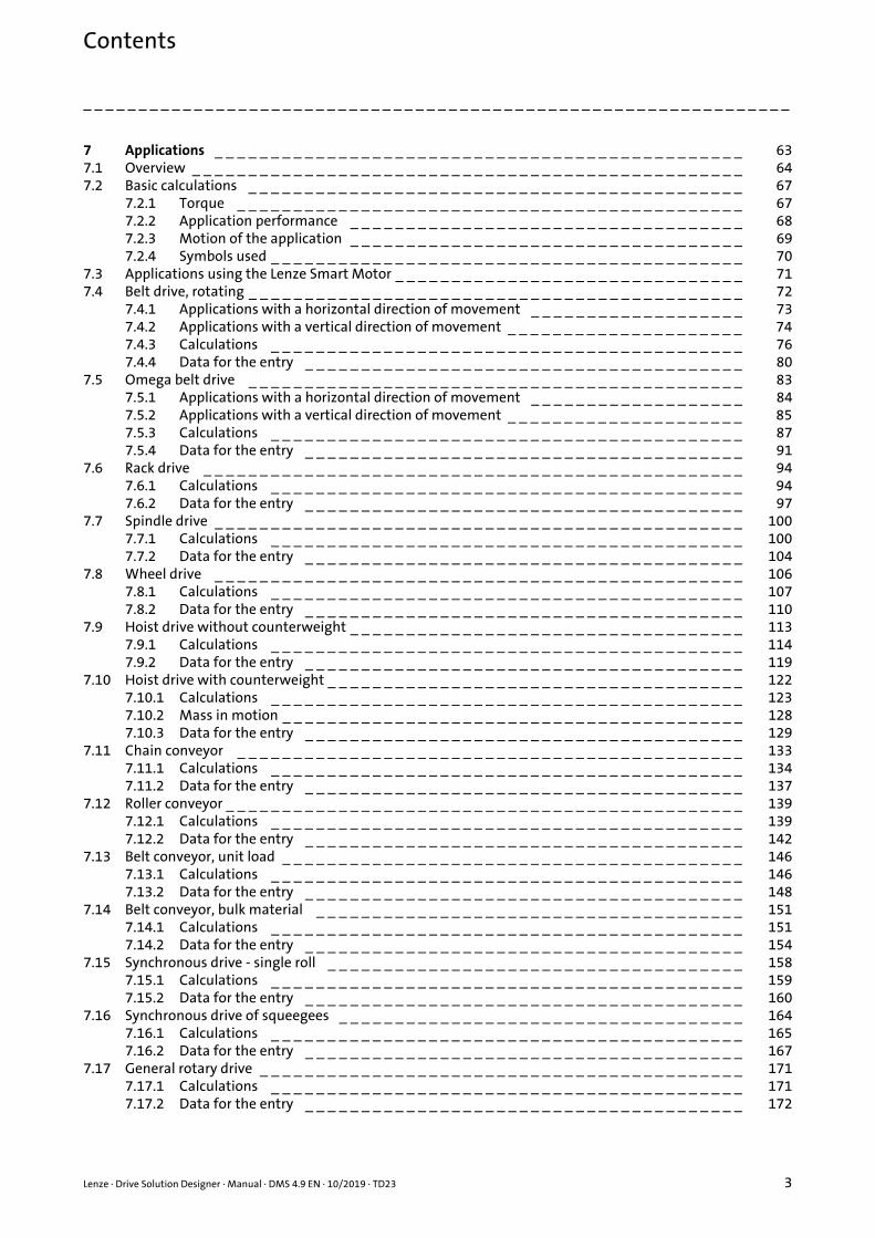
7 Applications _ _ _ _ _ _ _ _ _ _ _ _ _ _ _ _ _ _ _ _ _ _ _ _ _ _ _ _ _ _ _ _ _ _ _ _ _ _ _ _ _ _ _ _ _ _ _ 637.1 Overview _ _ _ _ _ _ _ _ _ _ _ _ _ _ _ _ _ _ _ _ _ _ _ _ _ _ _ _ _ _ _ _ _ _ _ _ _ _ _ _ _ _ _ _ _ _ _ _ _ 647.2 Basic calculations _ _ _ _ _ _ _ _ _ _ _ _ _ _ _ _ _ _ _ _ _ _ _ _ _ _ _ _ _ _ _ _ _ _ _ _ _ _ _ _ _ _ _ _ 67
7.2.1 Torque _ _ _ _ _ _ _ _ _ _ _ _ _ _ _ _ _ _ _ _ _ _ _ _ _ _ _ _ _ _ _ _ _ _ _ _ _ _ _ _ _ _ _ _ _ 677.2.2 Application performance _ _ _ _ _ _ _ _ _ _ _ _ _ _ _ _ _ _ _ _ _ _ _ _ _ _ _ _ _ _ _ _ _ _ _ 687.2.3 Motion of the application _ _ _ _ _ _ _ _ _ _ _ _ _ _ _ _ _ _ _ _ _ _ _ _ _ _ _ _ _ _ _ _ _ _ _ 697.2.4 Symbols used _ _ _ _ _ _ _ _ _ _ _ _ _ _ _ _ _ _ _ _ _ _ _ _ _ _ _ _ _ _ _ _ _ _ _ _ _ _ _ _ _ _ 70
7.3 Applications using the Lenze Smart Motor _ _ _ _ _ _ _ _ _ _ _ _ _ _ _ _ _ _ _ _ _ _ _ _ _ _ _ _ _ _ _ 717.4 Belt drive, rotating _ _ _ _ _ _ _ _ _ _ _ _ _ _ _ _ _ _ _ _ _ _ _ _ _ _ _ _ _ _ _ _ _ _ _ _ _ _ _ _ _ _ _ _ 72
7.4.1 Applications with a horizontal direction of movement _ _ _ _ _ _ _ _ _ _ _ _ _ _ _ _ _ _ _ 737.4.2 Applications with a vertical direction of movement _ _ _ _ _ _ _ _ _ _ _ _ _ _ _ _ _ _ _ _ _ 747.4.3 Calculations _ _ _ _ _ _ _ _ _ _ _ _ _ _ _ _ _ _ _ _ _ _ _ _ _ _ _ _ _ _ _ _ _ _ _ _ _ _ _ _ _ _ 767.4.4 Data for the entry _ _ _ _ _ _ _ _ _ _ _ _ _ _ _ _ _ _ _ _ _ _ _ _ _ _ _ _ _ _ _ _ _ _ _ _ _ _ _ 80
7.5 Omega belt drive _ _ _ _ _ _ _ _ _ _ _ _ _ _ _ _ _ _ _ _ _ _ _ _ _ _ _ _ _ _ _ _ _ _ _ _ _ _ _ _ _ _ _ _ 837.5.1 Applications with a horizontal direction of movement _ _ _ _ _ _ _ _ _ _ _ _ _ _ _ _ _ _ _ 847.5.2 Applications with a vertical direction of movement _ _ _ _ _ _ _ _ _ _ _ _ _ _ _ _ _ _ _ _ _ 857.5.3 Calculations _ _ _ _ _ _ _ _ _ _ _ _ _ _ _ _ _ _ _ _ _ _ _ _ _ _ _ _ _ _ _ _ _ _ _ _ _ _ _ _ _ _ 877.5.4 Data for the entry _ _ _ _ _ _ _ _ _ _ _ _ _ _ _ _ _ _ _ _ _ _ _ _ _ _ _ _ _ _ _ _ _ _ _ _ _ _ _ 91
7.6 Rack drive _ _ _ _ _ _ _ _ _ _ _ _ _ _ _ _ _ _ _ _ _ _ _ _ _ _ _ _ _ _ _ _ _ _ _ _ _ _ _ _ _ _ _ _ _ _ _ _ 947.6.1 Calculations _ _ _ _ _ _ _ _ _ _ _ _ _ _ _ _ _ _ _ _ _ _ _ _ _ _ _ _ _ _ _ _ _ _ _ _ _ _ _ _ _ _ 947.6.2 Data for the entry _ _ _ _ _ _ _ _ _ _ _ _ _ _ _ _ _ _ _ _ _ _ _ _ _ _ _ _ _ _ _ _ _ _ _ _ _ _ _ 97
7.7 Spindle drive _ _ _ _ _ _ _ _ _ _ _ _ _ _ _ _ _ _ _ _ _ _ _ _ _ _ _ _ _ _ _ _ _ _ _ _ _ _ _ _ _ _ _ _ _ _ _ 1007.7.1 Calculations _ _ _ _ _ _ _ _ _ _ _ _ _ _ _ _ _ _ _ _ _ _ _ _ _ _ _ _ _ _ _ _ _ _ _ _ _ _ _ _ _ _ 1007.7.2 Data for the entry _ _ _ _ _ _ _ _ _ _ _ _ _ _ _ _ _ _ _ _ _ _ _ _ _ _ _ _ _ _ _ _ _ _ _ _ _ _ _ 104
7.8 Wheel drive _ _ _ _ _ _ _ _ _ _ _ _ _ _ _ _ _ _ _ _ _ _ _ _ _ _ _ _ _ _ _ _ _ _ _ _ _ _ _ _ _ _ _ _ _ _ _ 1067.8.1 Calculations _ _ _ _ _ _ _ _ _ _ _ _ _ _ _ _ _ _ _ _ _ _ _ _ _ _ _ _ _ _ _ _ _ _ _ _ _ _ _ _ _ _ 1077.8.2 Data for the entry _ _ _ _ _ _ _ _ _ _ _ _ _ _ _ _ _ _ _ _ _ _ _ _ _ _ _ _ _ _ _ _ _ _ _ _ _ _ _ 110
7.9 Hoist drive without counterweight _ _ _ _ _ _ _ _ _ _ _ _ _ _ _ _ _ _ _ _ _ _ _ _ _ _ _ _ _ _ _ _ _ _ _ 1137.9.1 Calculations _ _ _ _ _ _ _ _ _ _ _ _ _ _ _ _ _ _ _ _ _ _ _ _ _ _ _ _ _ _ _ _ _ _ _ _ _ _ _ _ _ _ 1147.9.2 Data for the entry _ _ _ _ _ _ _ _ _ _ _ _ _ _ _ _ _ _ _ _ _ _ _ _ _ _ _ _ _ _ _ _ _ _ _ _ _ _ _ 119
7.10 Hoist drive with counterweight _ _ _ _ _ _ _ _ _ _ _ _ _ _ _ _ _ _ _ _ _ _ _ _ _ _ _ _ _ _ _ _ _ _ _ _ _ 1227.10.1 Calculations _ _ _ _ _ _ _ _ _ _ _ _ _ _ _ _ _ _ _ _ _ _ _ _ _ _ _ _ _ _ _ _ _ _ _ _ _ _ _ _ _ _ 1237.10.2 Mass in motion _ _ _ _ _ _ _ _ _ _ _ _ _ _ _ _ _ _ _ _ _ _ _ _ _ _ _ _ _ _ _ _ _ _ _ _ _ _ _ _ _ 1287.10.3 Data for the entry _ _ _ _ _ _ _ _ _ _ _ _ _ _ _ _ _ _ _ _ _ _ _ _ _ _ _ _ _ _ _ _ _ _ _ _ _ _ _ 129
7.11 Chain conveyor _ _ _ _ _ _ _ _ _ _ _ _ _ _ _ _ _ _ _ _ _ _ _ _ _ _ _ _ _ _ _ _ _ _ _ _ _ _ _ _ _ _ _ _ _ 1337.11.1 Calculations _ _ _ _ _ _ _ _ _ _ _ _ _ _ _ _ _ _ _ _ _ _ _ _ _ _ _ _ _ _ _ _ _ _ _ _ _ _ _ _ _ _ 1347.11.2 Data for the entry _ _ _ _ _ _ _ _ _ _ _ _ _ _ _ _ _ _ _ _ _ _ _ _ _ _ _ _ _ _ _ _ _ _ _ _ _ _ _ 137
7.12 Roller conveyor _ _ _ _ _ _ _ _ _ _ _ _ _ _ _ _ _ _ _ _ _ _ _ _ _ _ _ _ _ _ _ _ _ _ _ _ _ _ _ _ _ _ _ _ _ _ 1397.12.1 Calculations _ _ _ _ _ _ _ _ _ _ _ _ _ _ _ _ _ _ _ _ _ _ _ _ _ _ _ _ _ _ _ _ _ _ _ _ _ _ _ _ _ _ 1397.12.2 Data for the entry _ _ _ _ _ _ _ _ _ _ _ _ _ _ _ _ _ _ _ _ _ _ _ _ _ _ _ _ _ _ _ _ _ _ _ _ _ _ _ 142
7.13 Belt conveyor, unit load _ _ _ _ _ _ _ _ _ _ _ _ _ _ _ _ _ _ _ _ _ _ _ _ _ _ _ _ _ _ _ _ _ _ _ _ _ _ _ _ _ 1467.13.1 Calculations _ _ _ _ _ _ _ _ _ _ _ _ _ _ _ _ _ _ _ _ _ _ _ _ _ _ _ _ _ _ _ _ _ _ _ _ _ _ _ _ _ _ 1467.13.2 Data for the entry _ _ _ _ _ _ _ _ _ _ _ _ _ _ _ _ _ _ _ _ _ _ _ _ _ _ _ _ _ _ _ _ _ _ _ _ _ _ _ 148
7.14 Belt conveyor, bulk material _ _ _ _ _ _ _ _ _ _ _ _ _ _ _ _ _ _ _ _ _ _ _ _ _ _ _ _ _ _ _ _ _ _ _ _ _ _ 1517.14.1 Calculations _ _ _ _ _ _ _ _ _ _ _ _ _ _ _ _ _ _ _ _ _ _ _ _ _ _ _ _ _ _ _ _ _ _ _ _ _ _ _ _ _ _ 1517.14.2 Data for the entry _ _ _ _ _ _ _ _ _ _ _ _ _ _ _ _ _ _ _ _ _ _ _ _ _ _ _ _ _ _ _ _ _ _ _ _ _ _ _ 154
7.15 Synchronous drive - single roll _ _ _ _ _ _ _ _ _ _ _ _ _ _ _ _ _ _ _ _ _ _ _ _ _ _ _ _ _ _ _ _ _ _ _ _ _ 1587.15.1 Calculations _ _ _ _ _ _ _ _ _ _ _ _ _ _ _ _ _ _ _ _ _ _ _ _ _ _ _ _ _ _ _ _ _ _ _ _ _ _ _ _ _ _ 1597.15.2 Data for the entry _ _ _ _ _ _ _ _ _ _ _ _ _ _ _ _ _ _ _ _ _ _ _ _ _ _ _ _ _ _ _ _ _ _ _ _ _ _ _ 160
7.16 Synchronous drive of squeegees _ _ _ _ _ _ _ _ _ _ _ _ _ _ _ _ _ _ _ _ _ _ _ _ _ _ _ _ _ _ _ _ _ _ _ _ 1647.16.1 Calculations _ _ _ _ _ _ _ _ _ _ _ _ _ _ _ _ _ _ _ _ _ _ _ _ _ _ _ _ _ _ _ _ _ _ _ _ _ _ _ _ _ _ 1657.16.2 Data for the entry _ _ _ _ _ _ _ _ _ _ _ _ _ _ _ _ _ _ _ _ _ _ _ _ _ _ _ _ _ _ _ _ _ _ _ _ _ _ _ 167
7.17 General rotary drive _ _ _ _ _ _ _ _ _ _ _ _ _ _ _ _ _ _ _ _ _ _ _ _ _ _ _ _ _ _ _ _ _ _ _ _ _ _ _ _ _ _ _ 1717.17.1 Calculations _ _ _ _ _ _ _ _ _ _ _ _ _ _ _ _ _ _ _ _ _ _ _ _ _ _ _ _ _ _ _ _ _ _ _ _ _ _ _ _ _ _ 1717.17.2 Data for the entry _ _ _ _ _ _ _ _ _ _ _ _ _ _ _ _ _ _ _ _ _ _ _ _ _ _ _ _ _ _ _ _ _ _ _ _ _ _ _ 172

Contents
4 Lenze · Drive Solution Designer · Manual · DMS 4.9 EN · 10/2019 · TD23
_ _ _ _ _ _ _ _ _ _ _ _ _ _ _ _ _ _ _ _ _ _ _ _ _ _ _ _ _ _ _ _ _ _ _ _ _ _ _ _ _ _ _ _ _ _ _ _ _ _ _ _ _ _ _ _ _ _ _ _ _ _ _ _
7.18 Rotary table drive _ _ _ _ _ _ _ _ _ _ _ _ _ _ _ _ _ _ _ _ _ _ _ _ _ _ _ _ _ _ _ _ _ _ _ _ _ _ _ _ _ _ _ _ 1737.18.1 Calculations _ _ _ _ _ _ _ _ _ _ _ _ _ _ _ _ _ _ _ _ _ _ _ _ _ _ _ _ _ _ _ _ _ _ _ _ _ _ _ _ _ _ 1737.18.2 Data for the entry _ _ _ _ _ _ _ _ _ _ _ _ _ _ _ _ _ _ _ _ _ _ _ _ _ _ _ _ _ _ _ _ _ _ _ _ _ _ _ 175
7.19 Pump _ _ _ _ _ _ _ _ _ _ _ _ _ _ _ _ _ _ _ _ _ _ _ _ _ _ _ _ _ _ _ _ _ _ _ _ _ _ _ _ _ _ _ _ _ _ _ _ _ _ _ 1767.19.1 Calculations _ _ _ _ _ _ _ _ _ _ _ _ _ _ _ _ _ _ _ _ _ _ _ _ _ _ _ _ _ _ _ _ _ _ _ _ _ _ _ _ _ _ 1767.19.2 Data for the entry _ _ _ _ _ _ _ _ _ _ _ _ _ _ _ _ _ _ _ _ _ _ _ _ _ _ _ _ _ _ _ _ _ _ _ _ _ _ _ 178
7.20 Fan _ _ _ _ _ _ _ _ _ _ _ _ _ _ _ _ _ _ _ _ _ _ _ _ _ _ _ _ _ _ _ _ _ _ _ _ _ _ _ _ _ _ _ _ _ _ _ _ _ _ _ _ 1807.20.1 Calculations _ _ _ _ _ _ _ _ _ _ _ _ _ _ _ _ _ _ _ _ _ _ _ _ _ _ _ _ _ _ _ _ _ _ _ _ _ _ _ _ _ _ 1807.20.2 Data for the entry _ _ _ _ _ _ _ _ _ _ _ _ _ _ _ _ _ _ _ _ _ _ _ _ _ _ _ _ _ _ _ _ _ _ _ _ _ _ _ 182
7.21 Importing M-n-operating points _ _ _ _ _ _ _ _ _ _ _ _ _ _ _ _ _ _ _ _ _ _ _ _ _ _ _ _ _ _ _ _ _ _ _ _ 1847.21.1 Data for the entry _ _ _ _ _ _ _ _ _ _ _ _ _ _ _ _ _ _ _ _ _ _ _ _ _ _ _ _ _ _ _ _ _ _ _ _ _ _ _ 185
7.22 Size the multi-axis system _ _ _ _ _ _ _ _ _ _ _ _ _ _ _ _ _ _ _ _ _ _ _ _ _ _ _ _ _ _ _ _ _ _ _ _ _ _ _ 1867.22.1 Using braking energy _ _ _ _ _ _ _ _ _ _ _ _ _ _ _ _ _ _ _ _ _ _ _ _ _ _ _ _ _ _ _ _ _ _ _ _ _ 1867.22.2 Combining drive axes _ _ _ _ _ _ _ _ _ _ _ _ _ _ _ _ _ _ _ _ _ _ _ _ _ _ _ _ _ _ _ _ _ _ _ _ _ 1887.22.3 Combining Lenze products _ _ _ _ _ _ _ _ _ _ _ _ _ _ _ _ _ _ _ _ _ _ _ _ _ _ _ _ _ _ _ _ _ _ 1947.22.4 Dimensioning _ _ _ _ _ _ _ _ _ _ _ _ _ _ _ _ _ _ _ _ _ _ _ _ _ _ _ _ _ _ _ _ _ _ _ _ _ _ _ _ _ 1957.22.5 Parameterising projects _ _ _ _ _ _ _ _ _ _ _ _ _ _ _ _ _ _ _ _ _ _ _ _ _ _ _ _ _ _ _ _ _ _ _ _ 1967.22.6 Defining options _ _ _ _ _ _ _ _ _ _ _ _ _ _ _ _ _ _ _ _ _ _ _ _ _ _ _ _ _ _ _ _ _ _ _ _ _ _ _ _ 198
7.23 Winding drive for rewinder/unwinder _ _ _ _ _ _ _ _ _ _ _ _ _ _ _ _ _ _ _ _ _ _ _ _ _ _ _ _ _ _ _ _ _ 2007.23.1 Rewinder (single) _ _ _ _ _ _ _ _ _ _ _ _ _ _ _ _ _ _ _ _ _ _ _ _ _ _ _ _ _ _ _ _ _ _ _ _ _ _ _ _ 2007.23.2 Unwinder (single) _ _ _ _ _ _ _ _ _ _ _ _ _ _ _ _ _ _ _ _ _ _ _ _ _ _ _ _ _ _ _ _ _ _ _ _ _ _ _ 2057.23.3 Dimensioning strategies _ _ _ _ _ _ _ _ _ _ _ _ _ _ _ _ _ _ _ _ _ _ _ _ _ _ _ _ _ _ _ _ _ _ _ _ 2107.23.4 Traction-controlled winding drive _ _ _ _ _ _ _ _ _ _ _ _ _ _ _ _ _ _ _ _ _ _ _ _ _ _ _ _ _ _ 2127.23.5 Checking emergency-off scenarios _ _ _ _ _ _ _ _ _ _ _ _ _ _ _ _ _ _ _ _ _ _ _ _ _ _ _ _ _ _ 2137.23.6 Application data _ _ _ _ _ _ _ _ _ _ _ _ _ _ _ _ _ _ _ _ _ _ _ _ _ _ _ _ _ _ _ _ _ _ _ _ _ _ _ _ 2147.23.7 Data for the motion _ _ _ _ _ _ _ _ _ _ _ _ _ _ _ _ _ _ _ _ _ _ _ _ _ _ _ _ _ _ _ _ _ _ _ _ _ _ 221
7.24 Slider-crank mechanism _ _ _ _ _ _ _ _ _ _ _ _ _ _ _ _ _ _ _ _ _ _ _ _ _ _ _ _ _ _ _ _ _ _ _ _ _ _ _ _ _ 2267.24.1 Angle of tilt of the slider-crank mechanism _ _ _ _ _ _ _ _ _ _ _ _ _ _ _ _ _ _ _ _ _ _ _ _ _ 2277.24.2 Physical data on crank rod and crank disk _ _ _ _ _ _ _ _ _ _ _ _ _ _ _ _ _ _ _ _ _ _ _ _ _ _ 2287.24.3 Starting angle of the crank _ _ _ _ _ _ _ _ _ _ _ _ _ _ _ _ _ _ _ _ _ _ _ _ _ _ _ _ _ _ _ _ _ _ 2297.24.4 Offset of slider path _ _ _ _ _ _ _ _ _ _ _ _ _ _ _ _ _ _ _ _ _ _ _ _ _ _ _ _ _ _ _ _ _ _ _ _ _ _ 2317.24.5 Control modes for slider-crank mechanisms _ _ _ _ _ _ _ _ _ _ _ _ _ _ _ _ _ _ _ _ _ _ _ _ _ 2327.24.6 Calculated results _ _ _ _ _ _ _ _ _ _ _ _ _ _ _ _ _ _ _ _ _ _ _ _ _ _ _ _ _ _ _ _ _ _ _ _ _ _ _ 2327.24.7 Data for the entry _ _ _ _ _ _ _ _ _ _ _ _ _ _ _ _ _ _ _ _ _ _ _ _ _ _ _ _ _ _ _ _ _ _ _ _ _ _ _ 233
7.25 Eccentric lift table _ _ _ _ _ _ _ _ _ _ _ _ _ _ _ _ _ _ _ _ _ _ _ _ _ _ _ _ _ _ _ _ _ _ _ _ _ _ _ _ _ _ _ _ 2367.25.1 Starting angle of the eccentric disk _ _ _ _ _ _ _ _ _ _ _ _ _ _ _ _ _ _ _ _ _ _ _ _ _ _ _ _ _ _ 2377.25.2 Data for the entry _ _ _ _ _ _ _ _ _ _ _ _ _ _ _ _ _ _ _ _ _ _ _ _ _ _ _ _ _ _ _ _ _ _ _ _ _ _ _ 238
8 Motion design _ _ _ _ _ _ _ _ _ _ _ _ _ _ _ _ _ _ _ _ _ _ _ _ _ _ _ _ _ _ _ _ _ _ _ _ _ _ _ _ _ _ _ _ _ _ 2408.1 Selection of motion profile _ _ _ _ _ _ _ _ _ _ _ _ _ _ _ _ _ _ _ _ _ _ _ _ _ _ _ _ _ _ _ _ _ _ _ _ _ _ _ 2408.2 MotionDesigner _ _ _ _ _ _ _ _ _ _ _ _ _ _ _ _ _ _ _ _ _ _ _ _ _ _ _ _ _ _ _ _ _ _ _ _ _ _ _ _ _ _ _ _ _ 241
8.2.1 Control and function elements _ _ _ _ _ _ _ _ _ _ _ _ _ _ _ _ _ _ _ _ _ _ _ _ _ _ _ _ _ _ _ _ 2428.2.2 Toolbar _ _ _ _ _ _ _ _ _ _ _ _ _ _ _ _ _ _ _ _ _ _ _ _ _ _ _ _ _ _ _ _ _ _ _ _ _ _ _ _ _ _ _ _ _ 2438.2.3 Screen divider _ _ _ _ _ _ _ _ _ _ _ _ _ _ _ _ _ _ _ _ _ _ _ _ _ _ _ _ _ _ _ _ _ _ _ _ _ _ _ _ _ 2448.2.4 Object area _ _ _ _ _ _ _ _ _ _ _ _ _ _ _ _ _ _ _ _ _ _ _ _ _ _ _ _ _ _ _ _ _ _ _ _ _ _ _ _ _ _ _ 2458.2.5 Managing motion profiles _ _ _ _ _ _ _ _ _ _ _ _ _ _ _ _ _ _ _ _ _ _ _ _ _ _ _ _ _ _ _ _ _ _ _ 2508.2.6 Graphic area _ _ _ _ _ _ _ _ _ _ _ _ _ _ _ _ _ _ _ _ _ _ _ _ _ _ _ _ _ _ _ _ _ _ _ _ _ _ _ _ _ _ 2558.2.7 Parameter area: Description _ _ _ _ _ _ _ _ _ _ _ _ _ _ _ _ _ _ _ _ _ _ _ _ _ _ _ _ _ _ _ _ _ _ 2638.2.8 Positioning _ _ _ _ _ _ _ _ _ _ _ _ _ _ _ _ _ _ _ _ _ _ _ _ _ _ _ _ _ _ _ _ _ _ _ _ _ _ _ _ _ _ _ 2718.2.9 Parameter area: Data for the entry _ _ _ _ _ _ _ _ _ _ _ _ _ _ _ _ _ _ _ _ _ _ _ _ _ _ _ _ _ _ 2738.2.10 Motion profile: application instructions _ _ _ _ _ _ _ _ _ _ _ _ _ _ _ _ _ _ _ _ _ _ _ _ _ _ _ 279

Lenze · Drive Solution Designer · Manual · DMS 4.9 EN · 10/2019 · TD23 5
Contents
_ _ _ _ _ _ _ _ _ _ _ _ _ _ _ _ _ _ _ _ _ _ _ _ _ _ _ _ _ _ _ _ _ _ _ _ _ _ _ _ _ _ _ _ _ _ _ _ _ _ _ _ _ _ _ _ _ _ _ _ _ _ _ _
8.3 Predefined motion profile according to operating mode _ _ _ _ _ _ _ _ _ _ _ _ _ _ _ _ _ _ _ _ _ _ _ 2868.3.1 S1, continuous operation _ _ _ _ _ _ _ _ _ _ _ _ _ _ _ _ _ _ _ _ _ _ _ _ _ _ _ _ _ _ _ _ _ _ _ 2868.3.2 S2, short-term operation _ _ _ _ _ _ _ _ _ _ _ _ _ _ _ _ _ _ _ _ _ _ _ _ _ _ _ _ _ _ _ _ _ _ _ 2878.3.3 Intermittent operation S3, S4, S5 _ _ _ _ _ _ _ _ _ _ _ _ _ _ _ _ _ _ _ _ _ _ _ _ _ _ _ _ _ _ _ 2888.3.4 Intermittent load S6, S7 _ _ _ _ _ _ _ _ _ _ _ _ _ _ _ _ _ _ _ _ _ _ _ _ _ _ _ _ _ _ _ _ _ _ _ _ 2898.3.5 Data for the entry _ _ _ _ _ _ _ _ _ _ _ _ _ _ _ _ _ _ _ _ _ _ _ _ _ _ _ _ _ _ _ _ _ _ _ _ _ _ _ 290
9 Mains and environment _ _ _ _ _ _ _ _ _ _ _ _ _ _ _ _ _ _ _ _ _ _ _ _ _ _ _ _ _ _ _ _ _ _ _ _ _ _ _ _ _ 2939.1 Electrical supply system _ _ _ _ _ _ _ _ _ _ _ _ _ _ _ _ _ _ _ _ _ _ _ _ _ _ _ _ _ _ _ _ _ _ _ _ _ _ _ _ _ 293
9.1.1 Power system _ _ _ _ _ _ _ _ _ _ _ _ _ _ _ _ _ _ _ _ _ _ _ _ _ _ _ _ _ _ _ _ _ _ _ _ _ _ _ _ _ 2939.2 Ambient conditions _ _ _ _ _ _ _ _ _ _ _ _ _ _ _ _ _ _ _ _ _ _ _ _ _ _ _ _ _ _ _ _ _ _ _ _ _ _ _ _ _ _ _ 294
9.2.1 Max. ambient temperature, motor/gearbox _ _ _ _ _ _ _ _ _ _ _ _ _ _ _ _ _ _ _ _ _ _ _ _ _ 2949.2.2 Max. ambient temperature, inverter _ _ _ _ _ _ _ _ _ _ _ _ _ _ _ _ _ _ _ _ _ _ _ _ _ _ _ _ _ 2959.2.3 Site altitude _ _ _ _ _ _ _ _ _ _ _ _ _ _ _ _ _ _ _ _ _ _ _ _ _ _ _ _ _ _ _ _ _ _ _ _ _ _ _ _ _ _ 296
9.3 Calculation of the mains current _ _ _ _ _ _ _ _ _ _ _ _ _ _ _ _ _ _ _ _ _ _ _ _ _ _ _ _ _ _ _ _ _ _ _ _ 297
10 Structure of the drive axis _ _ _ _ _ _ _ _ _ _ _ _ _ _ _ _ _ _ _ _ _ _ _ _ _ _ _ _ _ _ _ _ _ _ _ _ _ _ _ _ 29810.1 Mechanical drive axis _ _ _ _ _ _ _ _ _ _ _ _ _ _ _ _ _ _ _ _ _ _ _ _ _ _ _ _ _ _ _ _ _ _ _ _ _ _ _ _ _ _ 299
10.1.1 Lenze gearbox _ _ _ _ _ _ _ _ _ _ _ _ _ _ _ _ _ _ _ _ _ _ _ _ _ _ _ _ _ _ _ _ _ _ _ _ _ _ _ _ _ 29910.1.2 Additional drive element _ _ _ _ _ _ _ _ _ _ _ _ _ _ _ _ _ _ _ _ _ _ _ _ _ _ _ _ _ _ _ _ _ _ _ 30010.1.3 Feedback _ _ _ _ _ _ _ _ _ _ _ _ _ _ _ _ _ _ _ _ _ _ _ _ _ _ _ _ _ _ _ _ _ _ _ _ _ _ _ _ _ _ _ _ 30010.1.4 Electromechanical brake _ _ _ _ _ _ _ _ _ _ _ _ _ _ _ _ _ _ _ _ _ _ _ _ _ _ _ _ _ _ _ _ _ _ _ _ 300
10.2 Electrical drive axis _ _ _ _ _ _ _ _ _ _ _ _ _ _ _ _ _ _ _ _ _ _ _ _ _ _ _ _ _ _ _ _ _ _ _ _ _ _ _ _ _ _ _ 30110.2.1 Motor direct on line _ _ _ _ _ _ _ _ _ _ _ _ _ _ _ _ _ _ _ _ _ _ _ _ _ _ _ _ _ _ _ _ _ _ _ _ _ _ 30110.2.2 Inverter with mains supply (single-axis application) _ _ _ _ _ _ _ _ _ _ _ _ _ _ _ _ _ _ _ _ _ 30110.2.3 Inverter with DC supply (multi-axis application) _ _ _ _ _ _ _ _ _ _ _ _ _ _ _ _ _ _ _ _ _ _ _ 301
10.3 Drive concept _ _ _ _ _ _ _ _ _ _ _ _ _ _ _ _ _ _ _ _ _ _ _ _ _ _ _ _ _ _ _ _ _ _ _ _ _ _ _ _ _ _ _ _ _ _ 30210.3.1 Display of user motor _ _ _ _ _ _ _ _ _ _ _ _ _ _ _ _ _ _ _ _ _ _ _ _ _ _ _ _ _ _ _ _ _ _ _ _ _ 30310.3.2 Gearbox _ _ _ _ _ _ _ _ _ _ _ _ _ _ _ _ _ _ _ _ _ _ _ _ _ _ _ _ _ _ _ _ _ _ _ _ _ _ _ _ _ _ _ _ _ 30410.3.3 Gearbox / motor mounting _ _ _ _ _ _ _ _ _ _ _ _ _ _ _ _ _ _ _ _ _ _ _ _ _ _ _ _ _ _ _ _ _ _ 30710.3.4 Motor _ _ _ _ _ _ _ _ _ _ _ _ _ _ _ _ _ _ _ _ _ _ _ _ _ _ _ _ _ _ _ _ _ _ _ _ _ _ _ _ _ _ _ _ _ _ 30810.3.5 Inverter _ _ _ _ _ _ _ _ _ _ _ _ _ _ _ _ _ _ _ _ _ _ _ _ _ _ _ _ _ _ _ _ _ _ _ _ _ _ _ _ _ _ _ _ _ 31310.3.6 Overview of motor/inverter control types _ _ _ _ _ _ _ _ _ _ _ _ _ _ _ _ _ _ _ _ _ _ _ _ _ _ 32110.3.7 Selection help: Products for drive systems (without winders) _ _ _ _ _ _ _ _ _ _ _ _ _ _ _ _ 32610.3.8 Selection help: Products for winding drive systems _ _ _ _ _ _ _ _ _ _ _ _ _ _ _ _ _ _ _ _ _ 32710.3.9 Selection help: Control types for winding drive systems _ _ _ _ _ _ _ _ _ _ _ _ _ _ _ _ _ _ 329
11 Drive Dimensioning _ _ _ _ _ _ _ _ _ _ _ _ _ _ _ _ _ _ _ _ _ _ _ _ _ _ _ _ _ _ _ _ _ _ _ _ _ _ _ _ _ _ _ 33011.1 Preselection of the geared motor _ _ _ _ _ _ _ _ _ _ _ _ _ _ _ _ _ _ _ _ _ _ _ _ _ _ _ _ _ _ _ _ _ _ _ _ 330
11.1.1 Origin of motor _ _ _ _ _ _ _ _ _ _ _ _ _ _ _ _ _ _ _ _ _ _ _ _ _ _ _ _ _ _ _ _ _ _ _ _ _ _ _ _ _ 33011.1.2 Motor group _ _ _ _ _ _ _ _ _ _ _ _ _ _ _ _ _ _ _ _ _ _ _ _ _ _ _ _ _ _ _ _ _ _ _ _ _ _ _ _ _ _ 33111.1.3 Additional moment of inertia, motor shaft _ _ _ _ _ _ _ _ _ _ _ _ _ _ _ _ _ _ _ _ _ _ _ _ _ _ 33211.1.4 Mounting position _ _ _ _ _ _ _ _ _ _ _ _ _ _ _ _ _ _ _ _ _ _ _ _ _ _ _ _ _ _ _ _ _ _ _ _ _ _ _ 33311.1.5 Average daily operating time _ _ _ _ _ _ _ _ _ _ _ _ _ _ _ _ _ _ _ _ _ _ _ _ _ _ _ _ _ _ _ _ _ 33511.1.6 Additional drive element (K) _ _ _ _ _ _ _ _ _ _ _ _ _ _ _ _ _ _ _ _ _ _ _ _ _ _ _ _ _ _ _ _ _ _ 33511.1.7 Energy-saving function _ _ _ _ _ _ _ _ _ _ _ _ _ _ _ _ _ _ _ _ _ _ _ _ _ _ _ _ _ _ _ _ _ _ _ _ 33511.1.8 Minimum ratio (K) _ _ _ _ _ _ _ _ _ _ _ _ _ _ _ _ _ _ _ _ _ _ _ _ _ _ _ _ _ _ _ _ _ _ _ _ _ _ _ 33611.1.9 Maximum ratio (K) _ _ _ _ _ _ _ _ _ _ _ _ _ _ _ _ _ _ _ _ _ _ _ _ _ _ _ _ _ _ _ _ _ _ _ _ _ _ _ 336
11.2 Motor selection _ _ _ _ _ _ _ _ _ _ _ _ _ _ _ _ _ _ _ _ _ _ _ _ _ _ _ _ _ _ _ _ _ _ _ _ _ _ _ _ _ _ _ _ _ 33711.2.1 Selection table _ _ _ _ _ _ _ _ _ _ _ _ _ _ _ _ _ _ _ _ _ _ _ _ _ _ _ _ _ _ _ _ _ _ _ _ _ _ _ _ _ 33711.2.2 Torque/speed characteristic _ _ _ _ _ _ _ _ _ _ _ _ _ _ _ _ _ _ _ _ _ _ _ _ _ _ _ _ _ _ _ _ _ _ 340
11.3 Selection of Lenze Smart Motor _ _ _ _ _ _ _ _ _ _ _ _ _ _ _ _ _ _ _ _ _ _ _ _ _ _ _ _ _ _ _ _ _ _ _ _ _ 34311.3.1 Selection table _ _ _ _ _ _ _ _ _ _ _ _ _ _ _ _ _ _ _ _ _ _ _ _ _ _ _ _ _ _ _ _ _ _ _ _ _ _ _ _ _ 34311.3.2 Torque/speed characteristic _ _ _ _ _ _ _ _ _ _ _ _ _ _ _ _ _ _ _ _ _ _ _ _ _ _ _ _ _ _ _ _ _ _ 345

Contents
6 Lenze · Drive Solution Designer · Manual · DMS 4.9 EN · 10/2019 · TD23
_ _ _ _ _ _ _ _ _ _ _ _ _ _ _ _ _ _ _ _ _ _ _ _ _ _ _ _ _ _ _ _ _ _ _ _ _ _ _ _ _ _ _ _ _ _ _ _ _ _ _ _ _ _ _ _ _ _ _ _ _ _ _ _
11.4 Dimensioning criteria for the motor _ _ _ _ _ _ _ _ _ _ _ _ _ _ _ _ _ _ _ _ _ _ _ _ _ _ _ _ _ _ _ _ _ _ 34711.4.1 Motors for 87-Hz operation _ _ _ _ _ _ _ _ _ _ _ _ _ _ _ _ _ _ _ _ _ _ _ _ _ _ _ _ _ _ _ _ _ _ 34711.4.2 Motors for 120-Hz operation _ _ _ _ _ _ _ _ _ _ _ _ _ _ _ _ _ _ _ _ _ _ _ _ _ _ _ _ _ _ _ _ _ 34711.4.3 Dimensioning guidelines and dimensioning information _ _ _ _ _ _ _ _ _ _ _ _ _ _ _ _ _ _ 34811.4.4 Field weakening in case of the winding drive _ _ _ _ _ _ _ _ _ _ _ _ _ _ _ _ _ _ _ _ _ _ _ _ 34811.4.5 Thermal utilisation _ _ _ _ _ _ _ _ _ _ _ _ _ _ _ _ _ _ _ _ _ _ _ _ _ _ _ _ _ _ _ _ _ _ _ _ _ _ _ 35011.4.6 Load-matching factor _ _ _ _ _ _ _ _ _ _ _ _ _ _ _ _ _ _ _ _ _ _ _ _ _ _ _ _ _ _ _ _ _ _ _ _ _ 35111.4.7 Radial forces/axial forces _ _ _ _ _ _ _ _ _ _ _ _ _ _ _ _ _ _ _ _ _ _ _ _ _ _ _ _ _ _ _ _ _ _ _ 357
11.5 Assigning the mounting flange to the user motor _ _ _ _ _ _ _ _ _ _ _ _ _ _ _ _ _ _ _ _ _ _ _ _ _ _ _ 35811.6 Mechanical brake selection _ _ _ _ _ _ _ _ _ _ _ _ _ _ _ _ _ _ _ _ _ _ _ _ _ _ _ _ _ _ _ _ _ _ _ _ _ _ _ 360
11.6.1 Selection table _ _ _ _ _ _ _ _ _ _ _ _ _ _ _ _ _ _ _ _ _ _ _ _ _ _ _ _ _ _ _ _ _ _ _ _ _ _ _ _ _ 36011.6.2 Brake types _ _ _ _ _ _ _ _ _ _ _ _ _ _ _ _ _ _ _ _ _ _ _ _ _ _ _ _ _ _ _ _ _ _ _ _ _ _ _ _ _ _ _ 36211.6.3 Holding torque diagram _ _ _ _ _ _ _ _ _ _ _ _ _ _ _ _ _ _ _ _ _ _ _ _ _ _ _ _ _ _ _ _ _ _ _ _ 36411.6.4 Dimensioning criteria _ _ _ _ _ _ _ _ _ _ _ _ _ _ _ _ _ _ _ _ _ _ _ _ _ _ _ _ _ _ _ _ _ _ _ _ _ 365
11.7 Lenze gearbox selection _ _ _ _ _ _ _ _ _ _ _ _ _ _ _ _ _ _ _ _ _ _ _ _ _ _ _ _ _ _ _ _ _ _ _ _ _ _ _ _ _ 36611.7.1 Selection table _ _ _ _ _ _ _ _ _ _ _ _ _ _ _ _ _ _ _ _ _ _ _ _ _ _ _ _ _ _ _ _ _ _ _ _ _ _ _ _ _ 36611.7.2 Torque/speed characteristic _ _ _ _ _ _ _ _ _ _ _ _ _ _ _ _ _ _ _ _ _ _ _ _ _ _ _ _ _ _ _ _ _ _ 369
11.8 Dimensioning criteria for the Lenze gearbox _ _ _ _ _ _ _ _ _ _ _ _ _ _ _ _ _ _ _ _ _ _ _ _ _ _ _ _ _ 37011.8.1 Check of the torque load _ _ _ _ _ _ _ _ _ _ _ _ _ _ _ _ _ _ _ _ _ _ _ _ _ _ _ _ _ _ _ _ _ _ _ _ 37011.8.2 Check of the speed load _ _ _ _ _ _ _ _ _ _ _ _ _ _ _ _ _ _ _ _ _ _ _ _ _ _ _ _ _ _ _ _ _ _ _ _ 37411.8.3 Radial and axial forces _ _ _ _ _ _ _ _ _ _ _ _ _ _ _ _ _ _ _ _ _ _ _ _ _ _ _ _ _ _ _ _ _ _ _ _ _ 37411.8.4 Thermal utilisation _ _ _ _ _ _ _ _ _ _ _ _ _ _ _ _ _ _ _ _ _ _ _ _ _ _ _ _ _ _ _ _ _ _ _ _ _ _ _ 374
11.9 Selection of an additional drive element _ _ _ _ _ _ _ _ _ _ _ _ _ _ _ _ _ _ _ _ _ _ _ _ _ _ _ _ _ _ _ _ 37711.9.1 Type identifier _ _ _ _ _ _ _ _ _ _ _ _ _ _ _ _ _ _ _ _ _ _ _ _ _ _ _ _ _ _ _ _ _ _ _ _ _ _ _ _ _ 37711.9.2 Ratio _ _ _ _ _ _ _ _ _ _ _ _ _ _ _ _ _ _ _ _ _ _ _ _ _ _ _ _ _ _ _ _ _ _ _ _ _ _ _ _ _ _ _ _ _ _ 37711.9.3 Efficiency _ _ _ _ _ _ _ _ _ _ _ _ _ _ _ _ _ _ _ _ _ _ _ _ _ _ _ _ _ _ _ _ _ _ _ _ _ _ _ _ _ _ _ _ 37711.9.4 Moment of inertia _ _ _ _ _ _ _ _ _ _ _ _ _ _ _ _ _ _ _ _ _ _ _ _ _ _ _ _ _ _ _ _ _ _ _ _ _ _ _ 37711.9.5 Permissible torque _ _ _ _ _ _ _ _ _ _ _ _ _ _ _ _ _ _ _ _ _ _ _ _ _ _ _ _ _ _ _ _ _ _ _ _ _ _ _ 37811.9.6 Constant torque loss _ _ _ _ _ _ _ _ _ _ _ _ _ _ _ _ _ _ _ _ _ _ _ _ _ _ _ _ _ _ _ _ _ _ _ _ _ _ 378
11.10 Inverter _ _ _ _ _ _ _ _ _ _ _ _ _ _ _ _ _ _ _ _ _ _ _ _ _ _ _ _ _ _ _ _ _ _ _ _ _ _ _ _ _ _ _ _ _ _ _ _ _ _ 37911.10.1 Preselection _ _ _ _ _ _ _ _ _ _ _ _ _ _ _ _ _ _ _ _ _ _ _ _ _ _ _ _ _ _ _ _ _ _ _ _ _ _ _ _ _ _ 37911.10.2 Selection table _ _ _ _ _ _ _ _ _ _ _ _ _ _ _ _ _ _ _ _ _ _ _ _ _ _ _ _ _ _ _ _ _ _ _ _ _ _ _ _ _ 38111.10.3 Dimensioning criteria _ _ _ _ _ _ _ _ _ _ _ _ _ _ _ _ _ _ _ _ _ _ _ _ _ _ _ _ _ _ _ _ _ _ _ _ _ 383
11.11 Feedback selection _ _ _ _ _ _ _ _ _ _ _ _ _ _ _ _ _ _ _ _ _ _ _ _ _ _ _ _ _ _ _ _ _ _ _ _ _ _ _ _ _ _ _ _ 39411.11.1 Selection table _ _ _ _ _ _ _ _ _ _ _ _ _ _ _ _ _ _ _ _ _ _ _ _ _ _ _ _ _ _ _ _ _ _ _ _ _ _ _ _ _ 39411.11.2 Dimensioning criteria _ _ _ _ _ _ _ _ _ _ _ _ _ _ _ _ _ _ _ _ _ _ _ _ _ _ _ _ _ _ _ _ _ _ _ _ _ 395
12 Components in the DC bus _ _ _ _ _ _ _ _ _ _ _ _ _ _ _ _ _ _ _ _ _ _ _ _ _ _ _ _ _ _ _ _ _ _ _ _ _ _ _ 39712.1 Supply concept _ _ _ _ _ _ _ _ _ _ _ _ _ _ _ _ _ _ _ _ _ _ _ _ _ _ _ _ _ _ _ _ _ _ _ _ _ _ _ _ _ _ _ _ _ _ 39712.2 Power supply module 9400 _ _ _ _ _ _ _ _ _ _ _ _ _ _ _ _ _ _ _ _ _ _ _ _ _ _ _ _ _ _ _ _ _ _ _ _ _ _ _ 398
12.2.1 Selection table _ _ _ _ _ _ _ _ _ _ _ _ _ _ _ _ _ _ _ _ _ _ _ _ _ _ _ _ _ _ _ _ _ _ _ _ _ _ _ _ _ 39812.2.2 Utilisation _ _ _ _ _ _ _ _ _ _ _ _ _ _ _ _ _ _ _ _ _ _ _ _ _ _ _ _ _ _ _ _ _ _ _ _ _ _ _ _ _ _ _ 399
12.3 9400 regenerative power supply module _ _ _ _ _ _ _ _ _ _ _ _ _ _ _ _ _ _ _ _ _ _ _ _ _ _ _ _ _ _ _ 40012.3.1 Selection table _ _ _ _ _ _ _ _ _ _ _ _ _ _ _ _ _ _ _ _ _ _ _ _ _ _ _ _ _ _ _ _ _ _ _ _ _ _ _ _ _ 40012.3.2 Utilisation _ _ _ _ _ _ _ _ _ _ _ _ _ _ _ _ _ _ _ _ _ _ _ _ _ _ _ _ _ _ _ _ _ _ _ _ _ _ _ _ _ _ _ 401
12.4 i700 power supply module _ _ _ _ _ _ _ _ _ _ _ _ _ _ _ _ _ _ _ _ _ _ _ _ _ _ _ _ _ _ _ _ _ _ _ _ _ _ _ 40212.4.1 Selection table _ _ _ _ _ _ _ _ _ _ _ _ _ _ _ _ _ _ _ _ _ _ _ _ _ _ _ _ _ _ _ _ _ _ _ _ _ _ _ _ _ 40212.4.2 Utilisation _ _ _ _ _ _ _ _ _ _ _ _ _ _ _ _ _ _ _ _ _ _ _ _ _ _ _ _ _ _ _ _ _ _ _ _ _ _ _ _ _ _ _ 403
12.5 Selection of components _ _ _ _ _ _ _ _ _ _ _ _ _ _ _ _ _ _ _ _ _ _ _ _ _ _ _ _ _ _ _ _ _ _ _ _ _ _ _ _ 404

Lenze · Drive Solution Designer · Manual · DMS 4.9 EN · 10/2019 · TD23 7
Contents
_ _ _ _ _ _ _ _ _ _ _ _ _ _ _ _ _ _ _ _ _ _ _ _ _ _ _ _ _ _ _ _ _ _ _ _ _ _ _ _ _ _ _ _ _ _ _ _ _ _ _ _ _ _ _ _ _ _ _ _ _ _ _ _
12.6 Brake resistor selection _ _ _ _ _ _ _ _ _ _ _ _ _ _ _ _ _ _ _ _ _ _ _ _ _ _ _ _ _ _ _ _ _ _ _ _ _ _ _ _ _ 40412.6.1 Number of integrated brake transistors _ _ _ _ _ _ _ _ _ _ _ _ _ _ _ _ _ _ _ _ _ _ _ _ _ _ _ 40512.6.2 Interconnection of brake resistors _ _ _ _ _ _ _ _ _ _ _ _ _ _ _ _ _ _ _ _ _ _ _ _ _ _ _ _ _ _ 40512.6.3 Selection table _ _ _ _ _ _ _ _ _ _ _ _ _ _ _ _ _ _ _ _ _ _ _ _ _ _ _ _ _ _ _ _ _ _ _ _ _ _ _ _ _ 40612.6.4 IP enclosure _ _ _ _ _ _ _ _ _ _ _ _ _ _ _ _ _ _ _ _ _ _ _ _ _ _ _ _ _ _ _ _ _ _ _ _ _ _ _ _ _ _ _ 40712.6.5 Integrated brake transistor utilisation _ _ _ _ _ _ _ _ _ _ _ _ _ _ _ _ _ _ _ _ _ _ _ _ _ _ _ _ 40812.6.6 Brake resistor utilisation _ _ _ _ _ _ _ _ _ _ _ _ _ _ _ _ _ _ _ _ _ _ _ _ _ _ _ _ _ _ _ _ _ _ _ _ 410
13 Product options _ _ _ _ _ _ _ _ _ _ _ _ _ _ _ _ _ _ _ _ _ _ _ _ _ _ _ _ _ _ _ _ _ _ _ _ _ _ _ _ _ _ _ _ _ 413
14 Energy efficiency _ _ _ _ _ _ _ _ _ _ _ _ _ _ _ _ _ _ _ _ _ _ _ _ _ _ _ _ _ _ _ _ _ _ _ _ _ _ _ _ _ _ _ _ _ 41414.1 Lenze BlueGreen Solutions _ _ _ _ _ _ _ _ _ _ _ _ _ _ _ _ _ _ _ _ _ _ _ _ _ _ _ _ _ _ _ _ _ _ _ _ _ _ _ 415
14.1.1 Basic data for the calculation of energy costs _ _ _ _ _ _ _ _ _ _ _ _ _ _ _ _ _ _ _ _ _ _ _ _ 41514.1.2 Project data _ _ _ _ _ _ _ _ _ _ _ _ _ _ _ _ _ _ _ _ _ _ _ _ _ _ _ _ _ _ _ _ _ _ _ _ _ _ _ _ _ _ _ 41614.1.3 Diagrams and project comparison _ _ _ _ _ _ _ _ _ _ _ _ _ _ _ _ _ _ _ _ _ _ _ _ _ _ _ _ _ _ 41614.1.4 Cost comparison TOP 3 _ _ _ _ _ _ _ _ _ _ _ _ _ _ _ _ _ _ _ _ _ _ _ _ _ _ _ _ _ _ _ _ _ _ _ _ 41714.1.5 The Energy Performance Certificate _ _ _ _ _ _ _ _ _ _ _ _ _ _ _ _ _ _ _ _ _ _ _ _ _ _ _ _ _ 41914.1.6 Energy and power flows _ _ _ _ _ _ _ _ _ _ _ _ _ _ _ _ _ _ _ _ _ _ _ _ _ _ _ _ _ _ _ _ _ _ _ _ 42014.1.7 Energy efficiency analysis with different load cycles _ _ _ _ _ _ _ _ _ _ _ _ _ _ _ _ _ _ _ _ 421
14.2 Tips for optimising the drive systems _ _ _ _ _ _ _ _ _ _ _ _ _ _ _ _ _ _ _ _ _ _ _ _ _ _ _ _ _ _ _ _ _ 42314.2.1 Cost-cutting potentials in applications _ _ _ _ _ _ _ _ _ _ _ _ _ _ _ _ _ _ _ _ _ _ _ _ _ _ _ _ 42414.2.2 Optimising the single-axis application _ _ _ _ _ _ _ _ _ _ _ _ _ _ _ _ _ _ _ _ _ _ _ _ _ _ _ _ 42514.2.3 Optimising the multi-axis application _ _ _ _ _ _ _ _ _ _ _ _ _ _ _ _ _ _ _ _ _ _ _ _ _ _ _ _ 42514.2.4 Energy efficiency in a multi-axis system _ _ _ _ _ _ _ _ _ _ _ _ _ _ _ _ _ _ _ _ _ _ _ _ _ _ _ 426
15 Results: comparing, optimising, logging _ _ _ _ _ _ _ _ _ _ _ _ _ _ _ _ _ _ _ _ _ _ _ _ _ _ _ _ _ _ _ _ 42915.1 Drawing _ _ _ _ _ _ _ _ _ _ _ _ _ _ _ _ _ _ _ _ _ _ _ _ _ _ _ _ _ _ _ _ _ _ _ _ _ _ _ _ _ _ _ _ _ _ _ _ _ 43015.2 Results _ _ _ _ _ _ _ _ _ _ _ _ _ _ _ _ _ _ _ _ _ _ _ _ _ _ _ _ _ _ _ _ _ _ _ _ _ _ _ _ _ _ _ _ _ _ _ _ _ _ 43415.3 Reports _ _ _ _ _ _ _ _ _ _ _ _ _ _ _ _ _ _ _ _ _ _ _ _ _ _ _ _ _ _ _ _ _ _ _ _ _ _ _ _ _ _ _ _ _ _ _ _ _ _ 435
15.3.1 Summarised report _ _ _ _ _ _ _ _ _ _ _ _ _ _ _ _ _ _ _ _ _ _ _ _ _ _ _ _ _ _ _ _ _ _ _ _ _ _ 43515.3.2 Detailed report _ _ _ _ _ _ _ _ _ _ _ _ _ _ _ _ _ _ _ _ _ _ _ _ _ _ _ _ _ _ _ _ _ _ _ _ _ _ _ _ _ 43615.3.3 Commissioning data _ _ _ _ _ _ _ _ _ _ _ _ _ _ _ _ _ _ _ _ _ _ _ _ _ _ _ _ _ _ _ _ _ _ _ _ _ _ 43615.3.4 SAP list of the configuration _ _ _ _ _ _ _ _ _ _ _ _ _ _ _ _ _ _ _ _ _ _ _ _ _ _ _ _ _ _ _ _ _ _ 43615.3.5 Output settings _ _ _ _ _ _ _ _ _ _ _ _ _ _ _ _ _ _ _ _ _ _ _ _ _ _ _ _ _ _ _ _ _ _ _ _ _ _ _ _ 438
15.4 Comparison and additional results _ _ _ _ _ _ _ _ _ _ _ _ _ _ _ _ _ _ _ _ _ _ _ _ _ _ _ _ _ _ _ _ _ _ _ 43915.4.1 Application Tuner _ _ _ _ _ _ _ _ _ _ _ _ _ _ _ _ _ _ _ _ _ _ _ _ _ _ _ _ _ _ _ _ _ _ _ _ _ _ _ 43915.4.2 Comparison of the open projects _ _ _ _ _ _ _ _ _ _ _ _ _ _ _ _ _ _ _ _ _ _ _ _ _ _ _ _ _ _ _ 43915.4.3 BlueGreen
Solutions _ _ _ _ _ _ _ _ _ _ _ _ _ _ _ _ _ _ _ _ _ _ _ _ _ _ _ _ _ _ _ _ _ _ _ _ _ _ _ _ _ _ _ _ 43915.5 Design data and transfer to the »EASY Product Finder« _ _ _ _ _ _ _ _ _ _ _ _ _ _ _ _ _ _ _ _ _ _ _ _ 440
15.5.1 CAD data in the geared motor _ _ _ _ _ _ _ _ _ _ _ _ _ _ _ _ _ _ _ _ _ _ _ _ _ _ _ _ _ _ _ _ _ 44015.5.2 CAD data
inverter _ _ _ _ _ _ _ _ _ _ _ _ _ _ _ _ _ _ _ _ _ _ _ _ _ _ _ _ _ _ _ _ _ _ _ _ _ _ _ _ _ _ _ _ _ 44015.5.3 Shopping cart for »EASY Product Finder« _ _ _ _ _ _ _ _ _ _ _ _ _ _ _ _ _ _ _ _ _ _ _ _ _ _ _ 441
15.6 Reserves with regard to the drive dimensioning _ _ _ _ _ _ _ _ _ _ _ _ _ _ _ _ _ _ _ _ _ _ _ _ _ _ _ _ 44215.6.1 Dynamic reserves _ _ _ _ _ _ _ _ _ _ _ _ _ _ _ _ _ _ _ _ _ _ _ _ _ _ _ _ _ _ _ _ _ _ _ _ _ _ _ 44215.6.2 Stationary reserves _ _ _ _ _ _ _ _ _ _ _ _ _ _ _ _ _ _ _ _ _ _ _ _ _ _ _ _ _ _ _ _ _ _ _ _ _ _ _ 44215.6.3 Speed reserves _ _ _ _ _ _ _ _ _ _ _ _ _ _ _ _ _ _ _ _ _ _ _ _ _ _ _ _ _ _ _ _ _ _ _ _ _ _ _ _ _ 44315.6.4 Torque reserves of the motor _ _ _ _ _ _ _ _ _ _ _ _ _ _ _ _ _ _ _ _ _ _ _ _ _ _ _ _ _ _ _ _ _ 44315.6.5 Reserves for inverters, power supply modules, regenerative power supply modules _ _ _ 44315.6.6 Reserves for brake resistors and brake choppers _ _ _ _ _ _ _ _ _ _ _ _ _ _ _ _ _ _ _ _ _ _ _ 44415.6.7 Reserves for gearboxes _ _ _ _ _ _ _ _ _ _ _ _ _ _ _ _ _ _ _ _ _ _ _ _ _ _ _ _ _ _ _ _ _ _ _ _ 44515.6.8 Reserves for drive systems with an active load _ _ _ _ _ _ _ _ _ _ _ _ _ _ _ _ _ _ _ _ _ _ _ _ 44615.6.9 Reserves for drive systems with a passive load _ _ _ _ _ _ _ _ _ _ _ _ _ _ _ _ _ _ _ _ _ _ _ _ 446

Contents
8 Lenze · Drive Solution Designer · Manual · DMS 4.9 EN · 10/2019 · TD23
_ _ _ _ _ _ _ _ _ _ _ _ _ _ _ _ _ _ _ _ _ _ _ _ _ _ _ _ _ _ _ _ _ _ _ _ _ _ _ _ _ _ _ _ _ _ _ _ _ _ _ _ _ _ _ _ _ _ _ _ _ _ _ _
16 Manage user motors _ _ _ _ _ _ _ _ _ _ _ _ _ _ _ _ _ _ _ _ _ _ _ _ _ _ _ _ _ _ _ _ _ _ _ _ _ _ _ _ _ _ 44716.1 User interface _ _ _ _ _ _ _ _ _ _ _ _ _ _ _ _ _ _ _ _ _ _ _ _ _ _ _ _ _ _ _ _ _ _ _ _ _ _ _ _ _ _ _ _ _ _ 44816.2 Toolbar _ _ _ _ _ _ _ _ _ _ _ _ _ _ _ _ _ _ _ _ _ _ _ _ _ _ _ _ _ _ _ _ _ _ _ _ _ _ _ _ _ _ _ _ _ _ _ _ _ _ 44916.3 Management area _ _ _ _ _ _ _ _ _ _ _ _ _ _ _ _ _ _ _ _ _ _ _ _ _ _ _ _ _ _ _ _ _ _ _ _ _ _ _ _ _ _ _ _ 44916.4 Input area _ _ _ _ _ _ _ _ _ _ _ _ _ _ _ _ _ _ _ _ _ _ _ _ _ _ _ _ _ _ _ _ _ _ _ _ _ _ _ _ _ _ _ _ _ _ _ _ 450
16.4.1 "Technology" tab _ _ _ _ _ _ _ _ _ _ _ _ _ _ _ _ _ _ _ _ _ _ _ _ _ _ _ _ _ _ _ _ _ _ _ _ _ _ _ _ 45116.4.2 "Mechanical" tab _ _ _ _ _ _ _ _ _ _ _ _ _ _ _ _ _ _ _ _ _ _ _ _ _ _ _ _ _ _ _ _ _ _ _ _ _ _ _ _ 45216.4.3 "Electrical" tab _ _ _ _ _ _ _ _ _ _ _ _ _ _ _ _ _ _ _ _ _ _ _ _ _ _ _ _ _ _ _ _ _ _ _ _ _ _ _ _ _ 45416.4.4 "Equivalent circuit diagram" tab _ _ _ _ _ _ _ _ _ _ _ _ _ _ _ _ _ _ _ _ _ _ _ _ _ _ _ _ _ _ _ 45516.4.5 "Accessories" tab _ _ _ _ _ _ _ _ _ _ _ _ _ _ _ _ _ _ _ _ _ _ _ _ _ _ _ _ _ _ _ _ _ _ _ _ _ _ _ _ 45816.4.6 "Comment" tab _ _ _ _ _ _ _ _ _ _ _ _ _ _ _ _ _ _ _ _ _ _ _ _ _ _ _ _ _ _ _ _ _ _ _ _ _ _ _ _ _ 458
16.5 Checklist for the asynchronous motor _ _ _ _ _ _ _ _ _ _ _ _ _ _ _ _ _ _ _ _ _ _ _ _ _ _ _ _ _ _ _ _ _ 45916.6 Checklist for the synchronous motor _ _ _ _ _ _ _ _ _ _ _ _ _ _ _ _ _ _ _ _ _ _ _ _ _ _ _ _ _ _ _ _ _ _ 461
17 Auxiliary means _ _ _ _ _ _ _ _ _ _ _ _ _ _ _ _ _ _ _ _ _ _ _ _ _ _ _ _ _ _ _ _ _ _ _ _ _ _ _ _ _ _ _ _ _ 46317.1 Auxiliary calculator _ _ _ _ _ _ _ _ _ _ _ _ _ _ _ _ _ _ _ _ _ _ _ _ _ _ _ _ _ _ _ _ _ _ _ _ _ _ _ _ _ _ _ 464
17.1.1 Calculator (Microsoft® calculator) _ _ _ _ _ _ _ _ _ _ _ _ _ _ _ _ _ _ _ _ _ _ _ _ _ _ _ _ _ _ 46617.1.2 Mass calculator _ _ _ _ _ _ _ _ _ _ _ _ _ _ _ _ _ _ _ _ _ _ _ _ _ _ _ _ _ _ _ _ _ _ _ _ _ _ _ _ _ 46717.1.3 Inertial calculator _ _ _ _ _ _ _ _ _ _ _ _ _ _ _ _ _ _ _ _ _ _ _ _ _ _ _ _ _ _ _ _ _ _ _ _ _ _ _ 46917.1.4 Gearbox calculator _ _ _ _ _ _ _ _ _ _ _ _ _ _ _ _ _ _ _ _ _ _ _ _ _ _ _ _ _ _ _ _ _ _ _ _ _ _ _ 47217.1.5 "Pinion diameter" calculator _ _ _ _ _ _ _ _ _ _ _ _ _ _ _ _ _ _ _ _ _ _ _ _ _ _ _ _ _ _ _ _ _ _ 47417.1.6 "Mass of counterweight (hoist drive)" calculator _ _ _ _ _ _ _ _ _ _ _ _ _ _ _ _ _ _ _ _ _ _ 47517.1.7 "Mass of rope/cable (hoist drive)" calculator _ _ _ _ _ _ _ _ _ _ _ _ _ _ _ _ _ _ _ _ _ _ _ _ _ 47617.1.8 "Uniform load mass (material handling technology)" calculator _ _ _ _ _ _ _ _ _ _ _ _ _ _ 47717.1.9 "Mass of delivery volume (material handling technology)" calculator _ _ _ _ _ _ _ _ _ _ _ 47817.1.10 "Mass of belt" calculator _ _ _ _ _ _ _ _ _ _ _ _ _ _ _ _ _ _ _ _ _ _ _ _ _ _ _ _ _ _ _ _ _ _ _ _ 47917.1.11 "Backing force (material handling technology)" calculator _ _ _ _ _ _ _ _ _ _ _ _ _ _ _ _ _ 48017.1.12 "Travelling resistance" calculator _ _ _ _ _ _ _ _ _ _ _ _ _ _ _ _ _ _ _ _ _ _ _ _ _ _ _ _ _ _ _ 48117.1.13 "Leadscrew efficiency" calculator _ _ _ _ _ _ _ _ _ _ _ _ _ _ _ _ _ _ _ _ _ _ _ _ _ _ _ _ _ _ _ 484
17.2 Physical coefficients _ _ _ _ _ _ _ _ _ _ _ _ _ _ _ _ _ _ _ _ _ _ _ _ _ _ _ _ _ _ _ _ _ _ _ _ _ _ _ _ _ _ _ 48517.3 MotionDesigner _ _ _ _ _ _ _ _ _ _ _ _ _ _ _ _ _ _ _ _ _ _ _ _ _ _ _ _ _ _ _ _ _ _ _ _ _ _ _ _ _ _ _ _ _ 48617.4 Lenze intranet _ _ _ _ _ _ _ _ _ _ _ _ _ _ _ _ _ _ _ _ _ _ _ _ _ _ _ _ _ _ _ _ _ _ _ _ _ _ _ _ _ _ _ _ _ _ 48617.5 Lenze Internet _ _ _ _ _ _ _ _ _ _ _ _ _ _ _ _ _ _ _ _ _ _ _ _ _ _ _ _ _ _ _ _ _ _ _ _ _ _ _ _ _ _ _ _ _ _ 48717.6 Lenze «EASY Product Finder» _ _ _ _ _ _ _ _ _ _ _ _ _ _ _ _ _ _ _ _ _ _ _ _ _ _ _ _ _ _ _ _ _ _ _ _ _ _ 487
18 Restrictions of the drive dimensioning _ _ _ _ _ _ _ _ _ _ _ _ _ _ _ _ _ _ _ _ _ _ _ _ _ _ _ _ _ _ _ _ _ 48818.1 Field weakening _ _ _ _ _ _ _ _ _ _ _ _ _ _ _ _ _ _ _ _ _ _ _ _ _ _ _ _ _ _ _ _ _ _ _ _ _ _ _ _ _ _ _ _ _ 48818.2 Worldwide mains voltages and supply forms _ _ _ _ _ _ _ _ _ _ _ _ _ _ _ _ _ _ _ _ _ _ _ _ _ _ _ _ _ 48918.3 Undervoltages: Impact on operational performance _ _ _ _ _ _ _ _ _ _ _ _ _ _ _ _ _ _ _ _ _ _ _ _ _ 48918.4 Highly dynamic applications with acceleration times < 50 ms _ _ _ _ _ _ _ _ _ _ _ _ _ _ _ _ _ _ _ _ 48918.5 Feedback systems _ _ _ _ _ _ _ _ _ _ _ _ _ _ _ _ _ _ _ _ _ _ _ _ _ _ _ _ _ _ _ _ _ _ _ _ _ _ _ _ _ _ _ _ 48918.6 Mechanical brakes for winding drives _ _ _ _ _ _ _ _ _ _ _ _ _ _ _ _ _ _ _ _ _ _ _ _ _ _ _ _ _ _ _ _ _ 49018.7 Saturation effects in the motor at > 200 % Mrated _ _ _ _ _ _ _ _ _ _ _ _ _ _ _ _ _ _ _ _ _ _ _ _ _ _ 49118.8 Radial and axial loads of the motor or gearbox shaft _ _ _ _ _ _ _ _ _ _ _ _ _ _ _ _ _ _ _ _ _ _ _ _ _ 49218.9 Service brake, holding brake with safety function _ _ _ _ _ _ _ _ _ _ _ _ _ _ _ _ _ _ _ _ _ _ _ _ _ _ _ 49318.10 Displacement of the M-n characteristic _ _ _ _ _ _ _ _ _ _ _ _ _ _ _ _ _ _ _ _ _ _ _ _ _ _ _ _ _ _ _ _ 49418.11 Maximum permissible motor cable length _ _ _ _ _ _ _ _ _ _ _ _ _ _ _ _ _ _ _ _ _ _ _ _ _ _ _ _ _ _ 49518.12 Effects of low switching frequencies on the motor _ _ _ _ _ _ _ _ _ _ _ _ _ _ _ _ _ _ _ _ _ _ _ _ _ _ 49518.13 Motor temperature monitoring acc. to UL 508C _ _ _ _ _ _ _ _ _ _ _ _ _ _ _ _ _ _ _ _ _ _ _ _ _ _ _ _ 49618.14 Operation of inverters on the earth-leakage circuit breaker _ _ _ _ _ _ _ _ _ _ _ _ _ _ _ _ _ _ _ _ _ 49718.15 Qualitative requirements with regard to the application _ _ _ _ _ _ _ _ _ _ _ _ _ _ _ _ _ _ _ _ _ _ _ 49718.16 System disturbances _ _ _ _ _ _ _ _ _ _ _ _ _ _ _ _ _ _ _ _ _ _ _ _ _ _ _ _ _ _ _ _ _ _ _ _ _ _ _ _ _ _ 49718.17 Parallel operation of several motors on one inverter (group drives) _ _ _ _ _ _ _ _ _ _ _ _ _ _ _ _ _ 49818.18 Parallel operation of several motors on several inverters _ _ _ _ _ _ _ _ _ _ _ _ _ _ _ _ _ _ _ _ _ _ _ 49918.19 ATEX for gearbox _ _ _ _ _ _ _ _ _ _ _ _ _ _ _ _ _ _ _ _ _ _ _ _ _ _ _ _ _ _ _ _ _ _ _ _ _ _ _ _ _ _ _ _ 499

Lenze · Drive Solution Designer · Manual · DMS 4.9 EN · 10/2019 · TD23 9
Contents
_ _ _ _ _ _ _ _ _ _ _ _ _ _ _ _ _ _ _ _ _ _ _ _ _ _ _ _ _ _ _ _ _ _ _ _ _ _ _ _ _ _ _ _ _ _ _ _ _ _ _ _ _ _ _ _ _ _ _ _ _ _ _ _
18.20 Applications with low field frequencies _ _ _ _ _ _ _ _ _ _ _ _ _ _ _ _ _ _ _ _ _ _ _ _ _ _ _ _ _ _ _ _ 50018.21 Emergency-off scenarios _ _ _ _ _ _ _ _ _ _ _ _ _ _ _ _ _ _ _ _ _ _ _ _ _ _ _ _ _ _ _ _ _ _ _ _ _ _ _ _ 50018.22 Switching in the motor cable _ _ _ _ _ _ _ _ _ _ _ _ _ _ _ _ _ _ _ _ _ _ _ _ _ _ _ _ _ _ _ _ _ _ _ _ _ _ 50018.23 Filter in the motor cable _ _ _ _ _ _ _ _ _ _ _ _ _ _ _ _ _ _ _ _ _ _ _ _ _ _ _ _ _ _ _ _ _ _ _ _ _ _ _ _ _ 50018.24 Application of bearing current chokes _ _ _ _ _ _ _ _ _ _ _ _ _ _ _ _ _ _ _ _ _ _ _ _ _ _ _ _ _ _ _ _ _ 50118.25 Improved motor control with temperature detection _ _ _ _ _ _ _ _ _ _ _ _ _ _ _ _ _ _ _ _ _ _ _ _ _ 50118.26 Cooling servo motors without gearbox via mounting flange _ _ _ _ _ _ _ _ _ _ _ _ _ _ _ _ _ _ _ _ _ 50218.27 Permanent load at low motor speeds for applications acc. to UL _ _ _ _ _ _ _ _ _ _ _ _ _ _ _ _ _ _ _ 502
19 Drive sizing messages _ _ _ _ _ _ _ _ _ _ _ _ _ _ _ _ _ _ _ _ _ _ _ _ _ _ _ _ _ _ _ _ _ _ _ _ _ _ _ _ _ _ 50319.1 Application _ _ _ _ _ _ _ _ _ _ _ _ _ _ _ _ _ _ _ _ _ _ _ _ _ _ _ _ _ _ _ _ _ _ _ _ _ _ _ _ _ _ _ _ _ _ _ _ 503
19.1.1 Ratio of the tensile forces Fin / Fout > limit value _ _ _ _ _ _ _ _ _ _ _ _ _ _ _ _ _ _ _ _ _ _ _ 50319.1.2 Ratio of the tensile forces Fout / Fin > limit value _ _ _ _ _ _ _ _ _ _ _ _ _ _ _ _ _ _ _ _ _ _ _ 50319.1.3 Difference of the tensile forces Fin - Fout > limit value _ _ _ _ _ _ _ _ _ _ _ _ _ _ _ _ _ _ _ _ 50319.1.4 Speed of the application = 0 (standstill) _ _ _ _ _ _ _ _ _ _ _ _ _ _ _ _ _ _ _ _ _ _ _ _ _ _ _ 50419.1.5 Safety check of controller inhibit failed _ _ _ _ _ _ _ _ _ _ _ _ _ _ _ _ _ _ _ _ _ _ _ _ _ _ _ _ 50419.1.6 No values available for the torque of the application _ _ _ _ _ _ _ _ _ _ _ _ _ _ _ _ _ _ _ _ 50419.1.7 Parameter of the motion profile is not evaluated _ _ _ _ _ _ _ _ _ _ _ _ _ _ _ _ _ _ _ _ _ _ 50519.1.8 Utilisation of the DC busbar system is xxx % _ _ _ _ _ _ _ _ _ _ _ _ _ _ _ _ _ _ _ _ _ _ _ _ _ 50519.1.9 Torque setting range > 50 for winding control mode xxx _ _ _ _ _ _ _ _ _ _ _ _ _ _ _ _ _ _ 50519.1.10 Low-friction dancer required for tensile force setting range xxx _ _ _ _ _ _ _ _ _ _ _ _ _ _ 50619.1.11 Value range for the reel diameter not plausible _ _ _ _ _ _ _ _ _ _ _ _ _ _ _ _ _ _ _ _ _ _ _ 50619.1.12 Value range for the tensile force of the winder not plausible _ _ _ _ _ _ _ _ _ _ _ _ _ _ _ _ 50619.1.13 High breakaway torque of chain conveyor _ _ _ _ _ _ _ _ _ _ _ _ _ _ _ _ _ _ _ _ _ _ _ _ _ _ 50619.1.14 The data of the motion profile are inconsistent _ _ _ _ _ _ _ _ _ _ _ _ _ _ _ _ _ _ _ _ _ _ _ 50719.1.15 The length of the crank is greater than the length of the connecting rod _ _ _ _ _ _ _ _ _ 50719.1.16 The length of the connecting rod is shorter than double the length of the crank _ _ _ _ _ 50719.1.17 Push axis offset too large _ _ _ _ _ _ _ _ _ _ _ _ _ _ _ _ _ _ _ _ _ _ _ _ _ _ _ _ _ _ _ _ _ _ _ 50719.1.18 Number of interpolation points in the motion profile is too large _ _ _ _ _ _ _ _ _ _ _ _ _ 508
19.2 Drive system _ _ _ _ _ _ _ _ _ _ _ _ _ _ _ _ _ _ _ _ _ _ _ _ _ _ _ _ _ _ _ _ _ _ _ _ _ _ _ _ _ _ _ _ _ _ _ 50919.2.1 Utilisation >100 %, regarding the max. torque _ _ _ _ _ _ _ _ _ _ _ _ _ _ _ _ _ _ _ _ _ _ _ _ 50919.2.2 In the DC-bus connection, the braking circuit of the inverter is not checked _ _ _ _ _ _ _ _ 50919.2.3 In the DC-bus connection, the EMC protection of the device is ineffective _ _ _ _ _ _ _ _ _ 50919.2.4 Product has been discontinued _ _ _ _ _ _ _ _ _ _ _ _ _ _ _ _ _ _ _ _ _ _ _ _ _ _ _ _ _ _ _ _ 51019.2.5 No effective starting current limitation available _ _ _ _ _ _ _ _ _ _ _ _ _ _ _ _ _ _ _ _ _ _ 51019.2.6 Checking the drive system and the tensile force sensor _ _ _ _ _ _ _ _ _ _ _ _ _ _ _ _ _ _ _ 51019.2.7 Torque setting range yyy requires measures _ _ _ _ _ _ _ _ _ _ _ _ _ _ _ _ _ _ _ _ _ _ _ _ _ 51019.2.8 Torque setting range yyy and tensile force setting range zzz require measures _ _ _ _ _ _ 51119.2.9 Max. torque for emergency stop exceeded _ _ _ _ _ _ _ _ _ _ _ _ _ _ _ _ _ _ _ _ _ _ _ _ _ _ 51119.2.10 Product options for component are not available _ _ _ _ _ _ _ _ _ _ _ _ _ _ _ _ _ _ _ _ _ _ 512
19.3 Additional drive element _ _ _ _ _ _ _ _ _ _ _ _ _ _ _ _ _ _ _ _ _ _ _ _ _ _ _ _ _ _ _ _ _ _ _ _ _ _ _ _ 51319.3.1 Rated torque loss is exceeded _ _ _ _ _ _ _ _ _ _ _ _ _ _ _ _ _ _ _ _ _ _ _ _ _ _ _ _ _ _ _ _ _ 51319.3.2 Min. ratio (K) is higher than max. ratio (K) _ _ _ _ _ _ _ _ _ _ _ _ _ _ _ _ _ _ _ _ _ _ _ _ _ _ 513
19.4 Lenze gearbox _ _ _ _ _ _ _ _ _ _ _ _ _ _ _ _ _ _ _ _ _ _ _ _ _ _ _ _ _ _ _ _ _ _ _ _ _ _ _ _ _ _ _ _ _ _ 51419.4.1 Utilisation >100 % regarding the equivalent torque _ _ _ _ _ _ _ _ _ _ _ _ _ _ _ _ _ _ _ _ _ 51419.4.2 Utilisation > yyy %, regarding the max. torque _ _ _ _ _ _ _ _ _ _ _ _ _ _ _ _ _ _ _ _ _ _ _ _ 51419.4.3 Utilisation >100 % regarding the max. speed _ _ _ _ _ _ _ _ _ _ _ _ _ _ _ _ _ _ _ _ _ _ _ _ 51519.4.4 Utilisation >100 % regarding the thermal speed _ _ _ _ _ _ _ _ _ _ _ _ _ _ _ _ _ _ _ _ _ _ _ 51519.4.5 Utilisation of the clutch >100 % regarding the torque _ _ _ _ _ _ _ _ _ _ _ _ _ _ _ _ _ _ _ _ 51519.4.6 Utilisation of the clutch >100 % regarding the speed _ _ _ _ _ _ _ _ _ _ _ _ _ _ _ _ _ _ _ _ 51619.4.7 Thermal overload when mineral gearbox oil is used _ _ _ _ _ _ _ _ _ _ _ _ _ _ _ _ _ _ _ _ _ 51619.4.8 Utilisation is xxx %, regarding the max. torque _ _ _ _ _ _ _ _ _ _ _ _ _ _ _ _ _ _ _ _ _ _ _ 51619.4.9 Load of the shaft sealing ring is xxx %, regarding the speed _ _ _ _ _ _ _ _ _ _ _ _ _ _ _ _ 51719.4.10 Wear of the gearbox >100 % _ _ _ _ _ _ _ _ _ _ _ _ _ _ _ _ _ _ _ _ _ _ _ _ _ _ _ _ _ _ _ _ _ 517

Contents
10 Lenze · Drive Solution Designer · Manual · DMS 4.9 EN · 10/2019 · TD23
_ _ _ _ _ _ _ _ _ _ _ _ _ _ _ _ _ _ _ _ _ _ _ _ _ _ _ _ _ _ _ _ _ _ _ _ _ _ _ _ _ _ _ _ _ _ _ _ _ _ _ _ _ _ _ _ _ _ _ _ _ _ _ _
19.4.11 Using synthetic oil for gearboxes of the winding application _ _ _ _ _ _ _ _ _ _ _ _ _ _ _ _ 51719.4.12 No product options available _ _ _ _ _ _ _ _ _ _ _ _ _ _ _ _ _ _ _ _ _ _ _ _ _ _ _ _ _ _ _ _ _ 51819.4.13 Too low load capacity of the geared motor for applications with a safety encoder _ _ _ _ 518
19.5 Lenze motor _ _ _ _ _ _ _ _ _ _ _ _ _ _ _ _ _ _ _ _ _ _ _ _ _ _ _ _ _ _ _ _ _ _ _ _ _ _ _ _ _ _ _ _ _ _ _ 51919.5.1 Utilisation >100 %, regarding the effective torque _ _ _ _ _ _ _ _ _ _ _ _ _ _ _ _ _ _ _ _ _ 51919.5.2 Max. motor speed is higher than the permissible motor speed _ _ _ _ _ _ _ _ _ _ _ _ _ _ _ 51919.5.3 Max. output torque is higher than the permissible motor torque _ _ _ _ _ _ _ _ _ _ _ _ _ 51919.5.4 Motor is operated in the field weakening range _ _ _ _ _ _ _ _ _ _ _ _ _ _ _ _ _ _ _ _ _ _ _ 52019.5.5 Max. mismatch is higher than permissible mismatch _ _ _ _ _ _ _ _ _ _ _ _ _ _ _ _ _ _ _ _ 52019.5.6 Unstable control mode of the winding drive in the case of speed-controlled operation _ 52019.5.7 Required motor speed too low _ _ _ _ _ _ _ _ _ _ _ _ _ _ _ _ _ _ _ _ _ _ _ _ _ _ _ _ _ _ _ _ 52119.5.8 Max. permissible motor current of yyy is exceeded _ _ _ _ _ _ _ _ _ _ _ _ _ _ _ _ _ _ _ _ _ 52119.5.9 Overload of the motor >xxx % _ _ _ _ _ _ _ _ _ _ _ _ _ _ _ _ _ _ _ _ _ _ _ _ _ _ _ _ _ _ _ _ _ 52119.5.10 Max. permissible ambient temperature of the blower is exceeded _ _ _ _ _ _ _ _ _ _ _ _ _ 52219.5.11 A continuous operation characteristic for inverter operation is not available _ _ _ _ _ _ _ 52219.5.12 Motor temperature too high at switching frequency < 8 kHz _ _ _ _ _ _ _ _ _ _ _ _ _ _ _ _ 52219.5.13 Limit value of xxx % of the rated torque is exceeded _ _ _ _ _ _ _ _ _ _ _ _ _ _ _ _ _ _ _ _ 52319.5.14 Compliance with ErP Directive 2009/125/EC _ _ _ _ _ _ _ _ _ _ _ _ _ _ _ _ _ _ _ _ _ _ _ _ _ 52319.5.15 No check of the thermal motor utilisation in accordance with UL requirements _ _ _ _ _ 52419.5.16 Overdimensioned motor in the case of traction-controlled winding drive _ _ _ _ _ _ _ _ _ 52419.5.17 Speed-controlled winding drive may show unstable behaviour _ _ _ _ _ _ _ _ _ _ _ _ _ _ 52419.5.18 Field weakening factor kf > as winding ratio q _ _ _ _ _ _ _ _ _ _ _ _ _ _ _ _ _ _ _ _ _ _ _ _ 52519.5.19 Activate "brake at standstill" _ _ _ _ _ _ _ _ _ _ _ _ _ _ _ _ _ _ _ _ _ _ _ _ _ _ _ _ _ _ _ _ _ 52519.5.20 Activate "controller inhibit at standstill" _ _ _ _ _ _ _ _ _ _ _ _ _ _ _ _ _ _ _ _ _ _ _ _ _ _ _ 52519.5.21 Motor speed falls below the limit speed of 500 rpm _ _ _ _ _ _ _ _ _ _ _ _ _ _ _ _ _ _ _ _ _ 52619.5.22 Motor speed exceeds limit speed of 2600 rpm _ _ _ _ _ _ _ _ _ _ _ _ _ _ _ _ _ _ _ _ _ _ _ _ 52619.5.23 Thermal utilisation of the synchronous servo motor is exceeded _ _ _ _ _ _ _ _ _ _ _ _ _ _ 52619.5.24 Deceleration time exceeds permissible time of 20 s _ _ _ _ _ _ _ _ _ _ _ _ _ _ _ _ _ _ _ _ _ 52719.5.25 Acceleration time exceeds permissible time of 20 s _ _ _ _ _ _ _ _ _ _ _ _ _ _ _ _ _ _ _ _ _ 52719.5.26 Max. motor torque is exceeded _ _ _ _ _ _ _ _ _ _ _ _ _ _ _ _ _ _ _ _ _ _ _ _ _ _ _ _ _ _ _ _ 52719.5.27 Longer braking distance during operation in generator mode below 500 rpm _ _ _ _ _ _ _ 52819.5.28 Permissible ambient temperature exceeds 40 °C _ _ _ _ _ _ _ _ _ _ _ _ _ _ _ _ _ _ _ _ _ _ 52819.5.29 Incomplete check of emergency stop _ _ _ _ _ _ _ _ _ _ _ _ _ _ _ _ _ _ _ _ _ _ _ _ _ _ _ _ _ 52819.5.30 Deactivation of specific checks for the Lenze Smart Motor _ _ _ _ _ _ _ _ _ _ _ _ _ _ _ _ _ 52919.5.31 Additional check of the synchronous servo motor in the field weakening range required 52919.5.32 Ambient temperature too high _ _ _ _ _ _ _ _ _ _ _ _ _ _ _ _ _ _ _ _ _ _ _ _ _ _ _ _ _ _ _ _ 52919.5.33 Max. permissible site altitude exceeded _ _ _ _ _ _ _ _ _ _ _ _ _ _ _ _ _ _ _ _ _ _ _ _ _ _ _ 53019.5.34 Check of the standstill under load with real downtimes _ _ _ _ _ _ _ _ _ _ _ _ _ _ _ _ _ _ 530
19.6 Brake _ _ _ _ _ _ _ _ _ _ _ _ _ _ _ _ _ _ _ _ _ _ _ _ _ _ _ _ _ _ _ _ _ _ _ _ _ _ _ _ _ _ _ _ _ _ _ _ _ _ _ 53119.6.1 Rated torque/dimensioning torque < safety factor of the brake _ _ _ _ _ _ _ _ _ _ _ _ _ _ 53119.6.2 Holding brake: Function and emergency stop _ _ _ _ _ _ _ _ _ _ _ _ _ _ _ _ _ _ _ _ _ _ _ _ 53119.6.3 No brake available _ _ _ _ _ _ _ _ _ _ _ _ _ _ _ _ _ _ _ _ _ _ _ _ _ _ _ _ _ _ _ _ _ _ _ _ _ _ _ 53119.6.4 Permanent magnet holding brake is not suitable for hoist drives _ _ _ _ _ _ _ _ _ _ _ _ _ 53219.6.5 Import of a motion profile - no check of the mechanical brake _ _ _ _ _ _ _ _ _ _ _ _ _ _ _ 53219.6.6 Brake in the motion profile not activated - no check of the mechanical brake _ _ _ _ _ _ _ 53219.6.7 Holding brake is not suitable for the non-linear application _ _ _ _ _ _ _ _ _ _ _ _ _ _ _ _ 533
19.7 Feedback _ _ _ _ _ _ _ _ _ _ _ _ _ _ _ _ _ _ _ _ _ _ _ _ _ _ _ _ _ _ _ _ _ _ _ _ _ _ _ _ _ _ _ _ _ _ _ _ _ 53419.7.1 Inverter/feedback combination not possible _ _ _ _ _ _ _ _ _ _ _ _ _ _ _ _ _ _ _ _ _ _ _ _ _ 53419.7.2 No feedback selected _ _ _ _ _ _ _ _ _ _ _ _ _ _ _ _ _ _ _ _ _ _ _ _ _ _ _ _ _ _ _ _ _ _ _ _ _ 53419.7.3 Feedback system is not checked _ _ _ _ _ _ _ _ _ _ _ _ _ _ _ _ _ _ _ _ _ _ _ _ _ _ _ _ _ _ _ _ 53419.7.4 Feedback system for safety-oriented applications is not checked _ _ _ _ _ _ _ _ _ _ _ _ _ 53519.7.5 Unstable control response of the speed-controlled winding drive _ _ _ _ _ _ _ _ _ _ _ _ _ 53519.7.6 Evaluation of feedback not possible in One Cable Technology _ _ _ _ _ _ _ _ _ _ _ _ _ _ _ 53519.7.7 The feedback is designed in One Cable Technology _ _ _ _ _ _ _ _ _ _ _ _ _ _ _ _ _ _ _ _ _ 535

Lenze · Drive Solution Designer · Manual · DMS 4.9 EN · 10/2019 · TD23 11
Contents
_ _ _ _ _ _ _ _ _ _ _ _ _ _ _ _ _ _ _ _ _ _ _ _ _ _ _ _ _ _ _ _ _ _ _ _ _ _ _ _ _ _ _ _ _ _ _ _ _ _ _ _ _ _ _ _ _ _ _ _ _ _ _ _
19.8 Inverter _ _ _ _ _ _ _ _ _ _ _ _ _ _ _ _ _ _ _ _ _ _ _ _ _ _ _ _ _ _ _ _ _ _ _ _ _ _ _ _ _ _ _ _ _ _ _ _ _ _ 53619.8.1 Ambient temperature too high _ _ _ _ _ _ _ _ _ _ _ _ _ _ _ _ _ _ _ _ _ _ _ _ _ _ _ _ _ _ _ _ 53619.8.2 Max. permissible site altitude exceeded _ _ _ _ _ _ _ _ _ _ _ _ _ _ _ _ _ _ _ _ _ _ _ _ _ _ _ 53619.8.3 Max. output current exceeded _ _ _ _ _ _ _ _ _ _ _ _ _ _ _ _ _ _ _ _ _ _ _ _ _ _ _ _ _ _ _ _ 53619.8.4 Max. thermal utilisation >100 % _ _ _ _ _ _ _ _ _ _ _ _ _ _ _ _ _ _ _ _ _ _ _ _ _ _ _ _ _ _ _ 53719.8.5 Control mode not suitable for hoist drive _ _ _ _ _ _ _ _ _ _ _ _ _ _ _ _ _ _ _ _ _ _ _ _ _ _ 53719.8.6 Inverter designed as double axis _ _ _ _ _ _ _ _ _ _ _ _ _ _ _ _ _ _ _ _ _ _ _ _ _ _ _ _ _ _ _ 53719.8.7 Current resolution is not adapted to the motor _ _ _ _ _ _ _ _ _ _ _ _ _ _ _ _ _ _ _ _ _ _ _ 53819.8.8 Utilisation of the inverter >100 % _ _ _ _ _ _ _ _ _ _ _ _ _ _ _ _ _ _ _ _ _ _ _ _ _ _ _ _ _ _ _ 53819.8.9 Utilisation of the inverter too high after mains connection _ _ _ _ _ _ _ _ _ _ _ _ _ _ _ _ _ 53819.8.10 VFC plus control mode without feedback not permissible _ _ _ _ _ _ _ _ _ _ _ _ _ _ _ _ _ 53919.8.11 The SLVC control mode is not permissible for inverters >55 kW _ _ _ _ _ _ _ _ _ _ _ _ _ _ 53919.8.12 Too low braking torques at low speed _ _ _ _ _ _ _ _ _ _ _ _ _ _ _ _ _ _ _ _ _ _ _ _ _ _ _ _ 53919.8.13 Motor limit rating is exceeded _ _ _ _ _ _ _ _ _ _ _ _ _ _ _ _ _ _ _ _ _ _ _ _ _ _ _ _ _ _ _ _ 53919.8.14 The inverter cannot provide the rated output current _ _ _ _ _ _ _ _ _ _ _ _ _ _ _ _ _ _ _ _ 54019.8.15 VFC plus eco control mode for quasi-stationary drives _ _ _ _ _ _ _ _ _ _ _ _ _ _ _ _ _ _ _ 54019.8.16 Activate VVC control _ _ _ _ _ _ _ _ _ _ _ _ _ _ _ _ _ _ _ _ _ _ _ _ _ _ _ _ _ _ _ _ _ _ _ _ _ _ 54019.8.17 SLVC and VFC plus control modes not for synchronous motors _ _ _ _ _ _ _ _ _ _ _ _ _ _ _ 54119.8.18 No product options available _ _ _ _ _ _ _ _ _ _ _ _ _ _ _ _ _ _ _ _ _ _ _ _ _ _ _ _ _ _ _ _ _ 54119.8.19 Mains choke required _ _ _ _ _ _ _ _ _ _ _ _ _ _ _ _ _ _ _ _ _ _ _ _ _ _ _ _ _ _ _ _ _ _ _ _ _ 54119.8.20 Special measures for operation with increased rated power _ _ _ _ _ _ _ _ _ _ _ _ _ _ _ _ 54219.8.21 Motor control xxx not suitable for winding control mode yyy _ _ _ _ _ _ _ _ _ _ _ _ _ _ _ 54219.8.22 Motor control xxx suitable to a limited extent for winding control mode yyy _ _ _ _ _ _ _ 54219.8.23 No electrical brake components available _ _ _ _ _ _ _ _ _ _ _ _ _ _ _ _ _ _ _ _ _ _ _ _ _ _ 54319.8.24 I×t utilisation of the brake transistor is >100 % _ _ _ _ _ _ _ _ _ _ _ _ _ _ _ _ _ _ _ _ _ _ _ 54319.8.25 Thermal utilisation of the inverter is > 80 % _ _ _ _ _ _ _ _ _ _ _ _ _ _ _ _ _ _ _ _ _ _ _ _ _ 54319.8.26 Rated inverter current is < xxx % of the rated motor current _ _ _ _ _ _ _ _ _ _ _ _ _ _ _ _ 54419.8.27 Thermal sensor is not evaluated by the inverter _ _ _ _ _ _ _ _ _ _ _ _ _ _ _ _ _ _ _ _ _ _ _ 54419.8.28 Control characteristics not optimal with servo control _ _ _ _ _ _ _ _ _ _ _ _ _ _ _ _ _ _ _ 54419.8.29 Switching frequency reduction as a function of the I×t utilisation _ _ _ _ _ _ _ _ _ _ _ _ _ 54519.8.30 Combining the i950 servo inverter with products outside the i-series is not approved _ _ 54519.8.31 With specific switching frequencies, the hoist may sag _ _ _ _ _ _ _ _ _ _ _ _ _ _ _ _ _ _ _ 54519.8.32 Loss of control of the hoist drive with specific switching frequencies _ _ _ _ _ _ _ _ _ _ _ 54619.8.33 No fixed assignment between the motor and inverter power in the case of single mounting 546
19.9 Regenerative power supply module _ _ _ _ _ _ _ _ _ _ _ _ _ _ _ _ _ _ _ _ _ _ _ _ _ _ _ _ _ _ _ _ _ _ 54719.9.1 Ambient temperature too low _ _ _ _ _ _ _ _ _ _ _ _ _ _ _ _ _ _ _ _ _ _ _ _ _ _ _ _ _ _ _ _ 54719.9.2 Ambient temperature too high _ _ _ _ _ _ _ _ _ _ _ _ _ _ _ _ _ _ _ _ _ _ _ _ _ _ _ _ _ _ _ _ 54719.9.3 Max. site altitude exceeded _ _ _ _ _ _ _ _ _ _ _ _ _ _ _ _ _ _ _ _ _ _ _ _ _ _ _ _ _ _ _ _ _ _ 54719.9.4 Max. power in supply mode exceeded _ _ _ _ _ _ _ _ _ _ _ _ _ _ _ _ _ _ _ _ _ _ _ _ _ _ _ _ 54719.9.5 Utilisation relative to the permissible continuous power exceeded _ _ _ _ _ _ _ _ _ _ _ _ 54819.9.6 Max. DC-bus power (power recovery) too high _ _ _ _ _ _ _ _ _ _ _ _ _ _ _ _ _ _ _ _ _ _ _ _ 54819.9.7 I×t utilisation of the brake transistor is >100 % _ _ _ _ _ _ _ _ _ _ _ _ _ _ _ _ _ _ _ _ _ _ _ 54819.9.8 Permissible pulse power is exceeded _ _ _ _ _ _ _ _ _ _ _ _ _ _ _ _ _ _ _ _ _ _ _ _ _ _ _ _ _ 54819.9.9 Permissible power of the regenerative power supply module is exceeded _ _ _ _ _ _ _ _ _ 549
19.10 Power supply module _ _ _ _ _ _ _ _ _ _ _ _ _ _ _ _ _ _ _ _ _ _ _ _ _ _ _ _ _ _ _ _ _ _ _ _ _ _ _ _ _ _ 55019.10.1 Ambient temperature too low _ _ _ _ _ _ _ _ _ _ _ _ _ _ _ _ _ _ _ _ _ _ _ _ _ _ _ _ _ _ _ _ 55019.10.2 Ambient temperature too high _ _ _ _ _ _ _ _ _ _ _ _ _ _ _ _ _ _ _ _ _ _ _ _ _ _ _ _ _ _ _ _ 55019.10.3 Max. site altitude exceeded _ _ _ _ _ _ _ _ _ _ _ _ _ _ _ _ _ _ _ _ _ _ _ _ _ _ _ _ _ _ _ _ _ _ 55019.10.4 Utilisation exceeded, regarding the max power (supply) _ _ _ _ _ _ _ _ _ _ _ _ _ _ _ _ _ _ 55019.10.5 Utilisation exceeded, relative to the max. power of the brake transistor _ _ _ _ _ _ _ _ _ _ 55119.10.6 Utilisation >100 %, regarding the DC-bus power (supply) _ _ _ _ _ _ _ _ _ _ _ _ _ _ _ _ _ _ 55119.10.7 Utilisation of the power supply module is >100 % _ _ _ _ _ _ _ _ _ _ _ _ _ _ _ _ _ _ _ _ _ _ 551

Contents
12 Lenze · Drive Solution Designer · Manual · DMS 4.9 EN · 10/2019 · TD23
_ _ _ _ _ _ _ _ _ _ _ _ _ _ _ _ _ _ _ _ _ _ _ _ _ _ _ _ _ _ _ _ _ _ _ _ _ _ _ _ _ _ _ _ _ _ _ _ _ _ _ _ _ _ _ _ _ _ _ _ _ _ _ _
19.11 Brake chopper _ _ _ _ _ _ _ _ _ _ _ _ _ _ _ _ _ _ _ _ _ _ _ _ _ _ _ _ _ _ _ _ _ _ _ _ _ _ _ _ _ _ _ _ _ _ 55219.11.1 Ambient temperature of the brake chopper too high _ _ _ _ _ _ _ _ _ _ _ _ _ _ _ _ _ _ _ _ 55219.11.2 Permissible site altitude of the brake chopper exceeded _ _ _ _ _ _ _ _ _ _ _ _ _ _ _ _ _ _ 55219.11.3 Permanent utilisation of the brake chopper > 100 % _ _ _ _ _ _ _ _ _ _ _ _ _ _ _ _ _ _ _ _ 55219.11.4 Utilisation >100 %, regarding the peak braking power _ _ _ _ _ _ _ _ _ _ _ _ _ _ _ _ _ _ _ 55319.11.5 Regenerative power is not dissipated safely _ _ _ _ _ _ _ _ _ _ _ _ _ _ _ _ _ _ _ _ _ _ _ _ _ 553
19.12 Brake resistor _ _ _ _ _ _ _ _ _ _ _ _ _ _ _ _ _ _ _ _ _ _ _ _ _ _ _ _ _ _ _ _ _ _ _ _ _ _ _ _ _ _ _ _ _ _ 55419.12.1 Resulting brake resistance too low _ _ _ _ _ _ _ _ _ _ _ _ _ _ _ _ _ _ _ _ _ _ _ _ _ _ _ _ _ _ 55419.12.2 Permanent utilisation of the equivalent resistance > 100 % _ _ _ _ _ _ _ _ _ _ _ _ _ _ _ _ 55419.12.3 Max. utilisation of the equivalent resistance is >100 % _ _ _ _ _ _ _ _ _ _ _ _ _ _ _ _ _ _ _ 55419.12.4 Max. permissible resistance value is exceeded _ _ _ _ _ _ _ _ _ _ _ _ _ _ _ _ _ _ _ _ _ _ _ _ 55519.12.5 Thermal time constant of the brake resistor is too small _ _ _ _ _ _ _ _ _ _ _ _ _ _ _ _ _ _ 55519.12.6 Temperature monitoring for the built-in/attached brake resistor is activated _ _ _ _ _ _ _ 55519.12.7 Check internal brake resistors _ _ _ _ _ _ _ _ _ _ _ _ _ _ _ _ _ _ _ _ _ _ _ _ _ _ _ _ _ _ _ _ _ 55619.12.8 Utilisation of the brake resistor is >yyy % _ _ _ _ _ _ _ _ _ _ _ _ _ _ _ _ _ _ _ _ _ _ _ _ _ _ _ 556
19.13 User motor _ _ _ _ _ _ _ _ _ _ _ _ _ _ _ _ _ _ _ _ _ _ _ _ _ _ _ _ _ _ _ _ _ _ _ _ _ _ _ _ _ _ _ _ _ _ _ _ 55719.13.1 Limited check of the user motor _ _ _ _ _ _ _ _ _ _ _ _ _ _ _ _ _ _ _ _ _ _ _ _ _ _ _ _ _ _ _ 55719.13.2 No options available for the user motor _ _ _ _ _ _ _ _ _ _ _ _ _ _ _ _ _ _ _ _ _ _ _ _ _ _ _ 55719.13.3 Configure gearbox mounting flange for user motor _ _ _ _ _ _ _ _ _ _ _ _ _ _ _ _ _ _ _ _ _ 557
20 Feedback, help & support _ _ _ _ _ _ _ _ _ _ _ _ _ _ _ _ _ _ _ _ _ _ _ _ _ _ _ _ _ _ _ _ _ _ _ _ _ _ _ _ 55820.1 Acquisition of application data _ _ _ _ _ _ _ _ _ _ _ _ _ _ _ _ _ _ _ _ _ _ _ _ _ _ _ _ _ _ _ _ _ _ _ _ _ 558
21 Glossary _ _ _ _ _ _ _ _ _ _ _ _ _ _ _ _ _ _ _ _ _ _ _ _ _ _ _ _ _ _ _ _ _ _ _ _ _ _ _ _ _ _ _ _ _ _ _ _ _ 560
22 Index _ _ _ _ _ _ _ _ _ _ _ _ _ _ _ _ _ _ _ _ _ _ _ _ _ _ _ _ _ _ _ _ _ _ _ _ _ _ _ _ _ _ _ _ _ _ _ _ _ _ _ 564
Your opinion is important to us! _ _ _ _ _ _ _ _ _ _ _ _ _ _ _ _ _ _ _ _ _ _ _ _ _ _ _ _ _ _ _ _ _ _ _ _ 568

1 Notes on usage1.1 Licencing and contractual conditions
_ _ _ _ _ _ _ _ _ _ _ _ _ _ _ _ _ _ _ _ _ _ _ _ _ _ _ _ _ _ _ _ _ _ _ _ _ _ _ _ _ _ _ _ _ _ _ _ _ _ _ _ _ _ _ _ _ _ _ _ _ _ _ _
1 Notes on usage
1.1 Licencing and contractual conditions
The use of the »Drive Solution Designer« is only permitted if the user accepts the licencing andcontractual conditions in the currently valid version.
• The valid version of the licencing and contractual conditions can be found under http://www.Lenze.com
1.2 Terms and conditions
For deliveries and counselling services the respective valid terms and conditions of the Lenze groupapply.
• The valid terms and conditions can be found under http://www.Lenze.com
1.3 Important information on the program
The »Drive Solution Designer« supports you on the basis of Lenze products, in order to find a correctand feasible solution for a drive task.
• For this purpose, a knowledge base with inverters, motors, gearboxes, electrical brake units, mechanical brakes, and feedback systems is stored in the »Drive Solution Designer«, which is used for the calculation of the drive solution.
• The »Drive Solution Designer« not only calculates the physical connections by means of formulas, but filters suggested solutions from the knowledge base according to different criteria.
Note!
The product-specific data integrated into the »Drive Solution Designer« with regard to drive components are not subject to a cyclic revision service.
In case of doubt, the information in the currently valid product documentation (catalogues, operating instructions, system manuals, etc.) available in printed form and via the internet applies!
Lenze · Drive Solution Designer · Manual · DMS 4.9 EN · 10/2019 · TD23 13

1 Notes on usage1.3 Important information on the program
_ _ _ _ _ _ _ _ _ _ _ _ _ _ _ _ _ _ _ _ _ _ _ _ _ _ _ _ _ _ _ _ _ _ _ _ _ _ _ _ _ _ _ _ _ _ _ _ _ _ _ _ _ _ _ _ _ _ _ _ _ _ _ _
Why have we developed the DSD?
Drive systems become more and more powerful and have to be optimally adapted to mechatronicrequirements. The cost pressure in the field of engineering increases permanently. At the sametime, however, less time is available for planning, dimensioning, and selecting the drive system.These high market requirements have motivated us to develop an efficient software which cancarry out complex calculations of drive physics. The program is based on complex productknowledge and can be easily used by every engineer. With the DSD you can solve your drive taskprofessionally in a few minutes and document it consistently. Like this, others are able to followyour calculations anytime, too. Moreover, the DSD serves to optimise the application and the drivesystem regarding energy efficiency.
Who has developed the DSD?
The program was developed by drive specialists and computer scientists in cooperation withexperienced Lenze sales staff. The cooperation of this interdisciplinary development team makes itpossible to carry out practically relevant dimensioning processes with the DSD.
Who has worked with the DSD so far?
Lenze sales staff, Lenze customers, and universities work with the DSD worldwide today. Alreadysince 2002 we have gained experience with this design program for drives. On the basis of thisexperience, the DSD is continuously perfected and adapted to current needs.
What is dimensioned with the DSD and what isn't?
A dimensioning includes the drive components: gearbox, motor, inverter, encoder on the motorside, electrical brake units, regenerative power supply modules, and electromechanical brakes.
Further accessories such as mains filters, automation modules, drive software, etc., currently cannotbe configured in the DSD yet, however, they can be determined via the »EASY Product Finder«.
• The »EASY Product Finder« can be found on the Internet:http://www.Lenze.com "Product Finder" area
14 Lenze · Drive Solution Designer · Manual · DMS 4.9 EN · 10/2019 · TD23

1 Notes on usage1.3 Important information on the program
_ _ _ _ _ _ _ _ _ _ _ _ _ _ _ _ _ _ _ _ _ _ _ _ _ _ _ _ _ _ _ _ _ _ _ _ _ _ _ _ _ _ _ _ _ _ _ _ _ _ _ _ _ _ _ _ _ _ _ _ _ _ _ _
Who is responsible for the dimensioning result?
In the past years the DSD has stood the test of time during countless drive dimensioning processes.In the context of our quality management the program is maintained continuously.
• In the "Downloads" area at http://www.Lenze.com, free-of-charge service packs and updates are provided.
• The Application Knowledge Base (AKB) is an important means of support for your work with the DSD.In the AKB you'll find:• Release notes (notes for restrictions)• Frequently Asked Questions (FAQ)• Tips and tricks
• The AKB can be found in the internet:http://AKB.Lenze.de
All drive dimensionings with the DSD primarily are based on your default settings and the data thatyou have entered. When the program-based calculations are carried out, we therefore depend oncorrect and complete information by the customer. If our counselling services or programcalculations are incorrect, unfeasible, or incomplete, and if this is due to incorrect and incompleteinformation by the respective user, liability by Lenze is excluded.
If error messages of the program cannot be eliminated by other entries, or if there are other doubtsduring the use of the program, please consult your responsible Lenze sales representative at anyrate.
The dimensioning calculated by the DSD is based on general physical laws. If products of othermanufacturers are used, of course Lenze does not give a warranty for their function. After all: TheDSD carries out physical drive dimensioning. Characteristics of the operational performance of adrive solution therefore cannot be taken into consideration necessarily.
Lenze · Drive Solution Designer · Manual · DMS 4.9 EN · 10/2019 · TD23 15
2 About this documentation
_ _ _ _ _ _ _ _ _ _ _ _ _ _ _ _ _ _ _ _ _ _ _ _ _ _ _ _ _ _ _ _ _ _ _ _ _ _ _ _ _ _ _ _ _ _ _ _ _ _ _ _ _ _ _ _ _ _ _ _ _ _ _ _
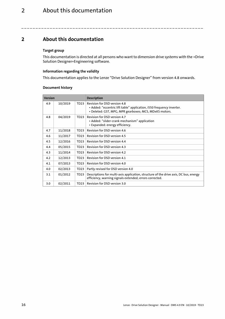
2 About this documentation
Target group
This documentation is directed at all persons who want to dimension drive systems with the »DriveSolution Designer«Engineering software.
Information regarding the validity
This documentation applies to the Lenze “Drive Solution Designer” from version 4.8 onwards.
Document history
Version Description
4.9 10/2019 TD23 Revision for DSD version 4.8• Added: “eccentric lift table” application, i550 frequency inverter.• Deleted: GST, MPG, MPR gearboxes; MCS, MDxKS motors.
4.8 04/2019 TD23 Revision for DSD version 4.7• Added: “slider-crank mechanism” application• Expanded: energy efficiency.
4.7 11/2018 TD23 Revision for DSD version 4.6
4.6 11/2017 TD23 Revision for DSD version 4.5
4.5 12/2016 TD23 Revision for DSD version 4.4
4.4 05/2015 TD23 Revision for DSD version 4.3
4.3 11/2014 TD23 Revision for DSD version 4.2
4.2 12/2013 TD23 Revision for DSD version 4.1
4.1 07/2013 TD23 Revision for DSD version 4.0
4.0 02/2013 TD23 Partly revised for DSD version 4.0
3.1 01/2012 TD23 Descriptions for multi-axis application, structure of the drive axis, DC bus, energy efficiency, warning signals extended; errors corrected.
3.0 02/2011 TD23 Revision for DSD version 3.0
16 Lenze · Drive Solution Designer · Manual · DMS 4.9 EN · 10/2019 · TD23

2 About this documentation2.1 Conventions used
_ _ _ _ _ _ _ _ _ _ _ _ _ _ _ _ _ _ _ _ _ _ _ _ _ _ _ _ _ _ _ _ _ _ _ _ _ _ _ _ _ _ _ _ _ _ _ _ _ _ _ _ _ _ _ _ _ _ _ _ _ _ _ _
2.1 Conventions used
This documentation uses the following conventions to distinguish the following types ofinformation:
Type of information Marking Examples/notes
Spelling of numbers
Decimal separator Point The decimal point is generally used.For example: 1234.56
Text
Version info Blue text colour Information that is only valid for or as from a certain software version of the inverter is marked accordingly in this documentation.Example: The function extension is available from software version V3.0 or higher!
Program name » « The Lenze PC software »PLC Designer«...
Window area Italics The Message window... / The Options dialog box...
Variable identifiers By setting bEnable to TRUE...
Control element Bold The OKbutton... / The Copy command ... / The Properties tab... / The Name input field ...
Sequence of menu commands
If several commands in succession are required to carry out a function, the individual commands are separated by an arrow: select the command FileOpen to...
Keyboard command <Bold> By <F1>, you call up the online help.
If a keyboard combination is required for a command, a "+" is placed between the keyboard identifiers: by <Shift>+<ESC>...
Program code Courier IF var1 < var2 THEN a = a + 1 END IF
Keyword Courier bold
Hyperlink Underlined Optically highlighted reference to another topic which is activated via mouse-click in this online documentation.
Icons
Page reference ( 17) Optically highlighted reference to another page which is activated via mouse-click in this online documentation.
Step-by-step instruction Step-by-step instructions are indicated by a pictograph.
Lenze · Drive Solution Designer · Manual · DMS 4.9 EN · 10/2019 · TD23 17

2 About this documentation2.2 Definition of the notes used
_ _ _ _ _ _ _ _ _ _ _ _ _ _ _ _ _ _ _ _ _ _ _ _ _ _ _ _ _ _ _ _ _ _ _ _ _ _ _ _ _ _ _ _ _ _ _ _ _ _ _ _ _ _ _ _ _ _ _ _ _ _ _ _
2.2 Definition of the notes used
In order to indicate dangers and important information, the following signal words and symbols areused:
Safety information
Layout of the safety instructions:
Application notes
Specific safety instructions and application notes for UL and UR
Pictograph and signal word!
(indicate the type and the degree of the danger)
Note
(describes the danger and provides information on its prevention)
Pictograph Signal word Meaning
Danger! Danger of injuries to persons by hazardous electrical voltageNote with regard to an imminent danger, which may result in death or severe injuries if the appropriate measures are not taken.
Danger! Danger of personal injury by a general source of dangerNote with regard to an imminent danger, which may result in death or severe injuries if the appropriate measures are not taken.
Stop! Danger of damage to material assetsNote with regard to a possible danger which may result in damage to material assets if the appropriate measures are not taken.
Pictograph Signal word Meaning
Note! Important note for the trouble-free function
Tip! Useful tip for simple handling
Pictograph Signal word Meaning
Warnings! Safety instruction or application note for the operation of a UL approved drive in UL approved systemsPossibly the drive system is not operated in a UL approved manner, if the appropriate measures are not taken.
Warnings! Safety instruction or application note for the operation of a UR approved drive in UL approved systemsPossibly the drive system is not operated in a UL approved manner, if the appropriate measures are not taken.
18 Lenze · Drive Solution Designer · Manual · DMS 4.9 EN · 10/2019 · TD23

3 User interface3.1 Control and function elements
_ _ _ _ _ _ _ _ _ _ _ _ _ _ _ _ _ _ _ _ _ _ _ _ _ _ _ _ _ _ _ _ _ _ _ _ _ _ _ _ _ _ _ _ _ _ _ _ _ _ _ _ _ _ _ _ _ _ _ _ _ _ _ _
3 User interface
This chapter introduces different control and function elements of the user interface to you andexplains how you can close the program again.
Control and function elements ( 19)
Shortcuts ( 39)
Closing the program ( 40)
3.1 Control and function elements
The user interface has the following control and function elements:
Menu bar ( 20)
Toolbar ( 25)
Drawing ( 28)
Navigation tree and result tree ( 33)
Input area ( 34)
Lenze · Drive Solution Designer · Manual · DMS 4.9 EN · 10/2019 · TD23 19

3 User interface3.1 Control and function elements
_ _ _ _ _ _ _ _ _ _ _ _ _ _ _ _ _ _ _ _ _ _ _ _ _ _ _ _ _ _ _ _ _ _ _ _ _ _ _ _ _ _ _ _ _ _ _ _ _ _ _ _ _ _ _ _ _ _ _ _ _ _ _ _
3.1.1 Menu bar
Via the Menu bar you have access to all menu commands.
• Click a menu to show the contained menu commands.
• Click a menu command to execute the connected function.• Grey menu commands are inactive during the current program state.
3.1.1.1 File
3.1.1.2 Edit
Menu command Function
New Create new project ( 48)
Open Open project ( 50)
Recently opened projects A list of the last five projects edited is provided
Close Close the open project.
Save Saving the project ( 52) • The current dimensioning state is saved in a project file.• If the project file is already existing, it is overwritten by the current
dimensioning status.
Save as... Save the current dimensioning status as a project with the specified name.• If the project name is different from the project that may currently be
edited, it is renamed.• The project name is displayed in the window headline.
Exit Closing the program ( 40)
Menu command Function
Move one step back Move one entry back in the navigation tree.
Move one step forward Move one entry forward in the navigation tree.
20 Lenze · Drive Solution Designer · Manual · DMS 4.9 EN · 10/2019 · TD23

3 User interface3.1 Control and function elements
_ _ _ _ _ _ _ _ _ _ _ _ _ _ _ _ _ _ _ _ _ _ _ _ _ _ _ _ _ _ _ _ _ _ _ _ _ _ _ _ _ _ _ _ _ _ _ _ _ _ _ _ _ _ _ _ _ _ _ _ _ _ _ _
3.1.1.3 View
3.1.1.4 Extras
Menu command Function
Notes • Note recording current dimensioning step• Display or write a comment on the current dimensioning step.
• All notes• Display, print or deletion of all comments that were created for the
project.Notes ( 37)
Messages Shows all warnings, notes and tips for the current drive dimensioning.Drive sizing messages ( 503)
Sizing report Create and display Log.• The dimensioning protocol that is generated can be printed or opened in
Microsoft Word.• The completeness of the report depends on the progress of the
dimensioning. If the dimensioning report is opened early, some components possibly are not displayed.
• At the end of the drive dimensioning the DSD offers different possibilities of presenting the results.
Reports ( 435)
Project comparison Compare projects among each other.• If several projects are open at the same time, they can be compared with
respect to the application and the utilisation of the components.Reports ( 435)
Product options for the EASY Product Finder / SAP
Shows product options of the components which are required for the purchase order with the »EASY Product Finder«. The »EASY Product Finder« is the electronic catalogue on the Lenze web page.
Menu command Function
Select language Change the language of the user interface.• German, English (British), Czech, Danish, English (American), Spanish,
French, Italian, Dutch, Russian, Swedish, Chinese (simplified) and Chinese (traditional) are provided.
Settings Settings ( 42)
Lenze · Drive Solution Designer · Manual · DMS 4.9 EN · 10/2019 · TD23 21
3 User interface3.1 Control and function elements
_ _ _ _ _ _ _ _ _ _ _ _ _ _ _ _ _ _ _ _ _ _ _ _ _ _ _ _ _ _ _ _ _ _ _ _ _ _ _ _ _ _ _ _ _ _ _ _ _ _ _ _ _ _ _ _ _ _ _ _ _ _ _ _
3.1.1.5 Tools
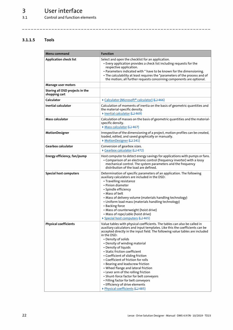
Menu command Function
Application check list Select and open the checklist for an application.• Every application provides a check list including requests for the
respective application.• Parameters indicated with * have to be known for the dimensioning.• The calculability at least requires the *parameters of the process and of
the motion; all further requests concerning components are optional.
Manage user motors
Storing all DSD projects in the shopping cart
Calculator Calculator (Microsoft® calculator) ( 466)
Inertial calculator Calculation of moments of inertia on the basis of geometric quantities and the material-specific density.Inertial calculator ( 469)
Mass calculator Calculation of masses on the basis of geometric quantities and the material-specific density.Mass calculator ( 467)
MotionDesigner Irrespective of the dimensioning of a project, motion profiles can be created, loaded, edited, and saved graphically or manually.MotionDesigner ( 241)
Gearbox calculator Conversion of gearbox sizes.Gearbox calculator ( 472)
Energy efficiency, fan/pump Host computer to detect energy savings for applications with pumps or fans.• Comparison of an electronic control (frequency inverter) with a lossy
mechanical control. The system parameters and the frequency distribution of the load are defined.
Special host computers Determination of specific parameters of an application. The following auxiliary calculators are included in the DSD:
• Travelling resistance• Pinion diameter• Spindle efficiency• Mass of belt• Mass of delivery volume (materials handling technology)• Uniform load mass (materials handling technology)• Backing force• Mass of counterweight (hoist drive)• Mass of rope/cable (hoist drive)Special host computers ( 465)
Physical coefficients Value tables with physical coefficients. The tables can also be called in auxiliary calculators and input templates. Like this the coefficients can be accepted directly in the input field. The following value tables are included in the DSD:
• Density of solids• Density of winding material• Density of liquids• Static friction coefficient• Coefficient of sliding friction• Coefficient of friction for rolls• Bearing and leadscrew friction• Wheel flange and lateral friction• Lever arm of the rolling friction• Shunt-force factor for belt conveyors• Filling factor for belt conveyors• Efficiency of drive elementsPhysical coefficients ( 485)
22 Lenze · Drive Solution Designer · Manual · DMS 4.9 EN · 10/2019 · TD23

3 User interface3.1 Control and function elements
_ _ _ _ _ _ _ _ _ _ _ _ _ _ _ _ _ _ _ _ _ _ _ _ _ _ _ _ _ _ _ _ _ _ _ _ _ _ _ _ _ _ _ _ _ _ _ _ _ _ _ _ _ _ _ _ _ _ _ _ _ _ _ _
3.1.1.6 Window
In the Window menu, all open DSD projects are listed. By selecting the corresponding menu itemthe project window is shown in the front. Project windows can be arranged using the followingmenu commands:
Collection of formulae "Drive solutions – formulae, tables and dimensioning" Manual in the PDF format.
• The reference book, formulary and tables provide the physical-mathematical basics in drive technology.
• The Manual can be read e.g. with the free-of-charge Adobe Reader.
Other tools (web links) Useful references to the Lenze web page. For using it, an internet connection is required.
• »EASY Product Finder«• Electronic catalogue to configure and/or order drive components and
accessories.• Sales documents, technical documentation, software• Generation of CAD data
• CAD data of Lenze motors• EPLAN macros for Lenze products
Menu command Function
Menu command Function
Cascading window If several windows are open, they are arranged one behind the other in a slightly staggered manner; by this other windows can be quickly selected.
Split window horizontally The display window is split horizontally into several areas. The projects are arranged one below the other.
Lenze · Drive Solution Designer · Manual · DMS 4.9 EN · 10/2019 · TD23 23

3 User interface3.1 Control and function elements
_ _ _ _ _ _ _ _ _ _ _ _ _ _ _ _ _ _ _ _ _ _ _ _ _ _ _ _ _ _ _ _ _ _ _ _ _ _ _ _ _ _ _ _ _ _ _ _ _ _ _ _ _ _ _ _ _ _ _ _ _ _ _ _
3.1.1.7 Help
Menu command Function
About DSD Open the information dialog showing the version number, registration information, and important information about DSD.
Help Open online help.
Sizing examples Examples of different drive dimensionings.• The DSD files can be used as a template for individual drive
dimensionings.
Check for updates Search for available updates for the DSD.• For using it, an internet connection is required.
Acquisition of application data Send log file with application information to the Lenze DSD server.• The log file contains important information on the Lenze development
for optimising the Drive Solution Designer.• For using it, an internet connection is required.Acquisition of application data ( 558)
Support on the intranet (AKB) Weblink to the Lenze Application Knowledge Base.• The Application Knowledge Base contains various information on the
Drive Solution Designer.• For using it, an internet connection is required.
Information on drive sizing
Support in the web Search the Lenze Application Knowledge Base for information and solutions.• For using it, an internet connection is required.
Software downloads The download area of the Lenze Application Knowledge Base contains the current DSD version and the published service packages.
• Always use the most current service package!• For using it, an internet connection is required.
Lenze on the Internet The Lenze webpage contains current information on the company and its products.
• For using it, an internet connection is required.http://www.Lenze.com
24 Lenze · Drive Solution Designer · Manual · DMS 4.9 EN · 10/2019 · TD23

3 User interface3.1 Control and function elements
_ _ _ _ _ _ _ _ _ _ _ _ _ _ _ _ _ _ _ _ _ _ _ _ _ _ _ _ _ _ _ _ _ _ _ _ _ _ _ _ _ _ _ _ _ _ _ _ _ _ _ _ _ _ _ _ _ _ _ _ _ _ _ _
3.1.2 Toolbar
Via the icons in the toolbar you can directly carry out the most frequently used functions.
• Click on an icon to carry out the respective function.
Symbol Menu command Keyboard command
Function
FileNew <Ctrl>+<N> Create new project ( 48)
FileOpen... <Ctrl>+<O> Open project ( 50)
FileSave <Ctrl>+<S> Saving the project ( 52)
EditUndo – Undo last action
EditRedo – Redo last undone action
ViewDimensioning report... – Reports ( 435)
ViewWarning signals... – Shows all warning signals, notes and tips for the current drive dimensioning.Drive sizing messages ( 503)
ToolsCalculator... – Calculator (Microsoft® calculator) ( 466)
ToolsInertial calculator... <Alt+T> Inertial calculator ( 469)
ToolsMass calculator... <Alt+M> Mass calculator ( 467)
ToolsMotionDesigner... – Creating, changing and saving motion profilesMotionDesigner ( 241)
ToolsEnergy-efficient fan/pump... – Detecting energy efficiency for applications with fans or pumps
ToolsGearbox calculator... <Alt+G> Gearbox calculator ( 472)
ToolsApplication checklist... – Data collection via checklists ( 53)
ToolsStore all DSD projects in the shopping cart...
– Shopping cart for »EASY Product Finder« ( 441)
ViewProject comparison... – Project comparison ( 59)
HelpHelp <F1> Call up help
– – Call up context-sensitive help
Lenze · Drive Solution Designer · Manual · DMS 4.9 EN · 10/2019 · TD23 25

3 User interface3.1 Control and function elements
_ _ _ _ _ _ _ _ _ _ _ _ _ _ _ _ _ _ _ _ _ _ _ _ _ _ _ _ _ _ _ _ _ _ _ _ _ _ _ _ _ _ _ _ _ _ _ _ _ _ _ _ _ _ _ _ _ _ _ _ _ _ _ _
The MotionDesigner serves to carry out the most frequently required functions via the icons in thetoolbar. Many functions can also be carried out via shortcuts. There are no menu commands. ( 241)
• Click on an icon to carry out the respective function.
Symbol Keyboard command
Function
<Ctrl>+<N> Create new motion profile.
<Ctrl>+<O> Load motion profile.Load the motion profile ( 250)
<Ctrl>+<S> Save motion profile.• When a newly created motion profile is saved, you are asked for the destination
of the Imp file.• When the motion profile is newly saved, the Imp file is updated.Save motion profile ( 251)
– Save motion profile as...• During the saving process, you are asked for the destination of the Imp file.Save motion profile ( 251)
– Import the motion profile with parameter profiles from an ASCII file.Importing profile data ( 252)
– Create note for motion profile• The note is attached to the "Motion" dimensioning step.• The function is only available with the application-dependent MotionDesigner.Notes ( 37)
<Del> Delete highlighted element.• The element is deleted permanently.
– Application analysis.• Shows diagrams and table of values via the entered and calculated values with
regard to a cycle of the motion profile.• The function is only available with the application-dependent MotionDesigner.
<Ctrl>+<Z> Undo last action.
<Ctrl>+<Y> Redo last undone action.
– Default settings for the dialog box.• Identical to the "Motion" register in the DSD menu ExtrasSettings.Settings ( 42) "Motion" register ( 43)
– Zoom x-axis and y-axis• Draw up a rectangle across the area to be zoomed in by keeping the left mouse
button pressed.
– Return to standard view.
<Ctrl>+<X> Cut the highlighted element and drag to the clipboard.
<Ctrl>+<C> Copy the highlighted element into the clipboard.
<Ctrl>+<V> Paste the element from the clipboard.
– Select the element or deactivate an active symbol.
26 Lenze · Drive Solution Designer · Manual · DMS 4.9 EN · 10/2019 · TD23

3 User interface3.1 Control and function elements
_ _ _ _ _ _ _ _ _ _ _ _ _ _ _ _ _ _ _ _ _ _ _ _ _ _ _ _ _ _ _ _ _ _ _ _ _ _ _ _ _ _ _ _ _ _ _ _ _ _ _ _ _ _ _ _ _ _ _ _ _ _ _ _
– Draw trapezoidal element.• The "Profile" register contains a selection of trapezoidal elements.Creating and editing elements ( 258) Parameter area: Description ( 263)
– Draw line.Creating and editing elements ( 258)
– Draw S-shaped element.Creating and editing elements ( 258)
– Import an individual motion profile or parameter profile.Importing profile data ( 252)
– Move elements to the left.• Moves separated elements on the drawing area to the left and connects them to
its preceding element.Shift elements automatically to the left ( 260)
– Combines the elements that form a trapezium so that an element is generated.• Only connected elements can be combined.• The elements to be combined must be highlighted.Combining elements ( 261)
– Undo combination.• Deactivate the combination of a trapezoidal element so that the elements can be
processed separately.
– Reflect highlighted element on the time axis.• This function can only be accessed via the context menu (click the right mouse
button).
– <Ctrl>+<Click> Duplicates an element in the drawing area when the element is right-clicked while the Ctrl key is pressed.
– <Ctrl>+<G> Shows or hides the grid of the drawing area.
– <Ctrl>+<A> Highlights all elements on the drawing area.
– <Shift>+<Click> In order to highlight several elements keep the <Shift> button pressed and right-click the elements.
Symbol Keyboard command
Function
Lenze · Drive Solution Designer · Manual · DMS 4.9 EN · 10/2019 · TD23 27

3 User interface3.1 Control and function elements
_ _ _ _ _ _ _ _ _ _ _ _ _ _ _ _ _ _ _ _ _ _ _ _ _ _ _ _ _ _ _ _ _ _ _ _ _ _ _ _ _ _ _ _ _ _ _ _ _ _ _ _ _ _ _ _ _ _ _ _ _ _ _ _
3.1.3 Drawing
The drawing visualises the current state of the drive dimensioning.
Notes
• At the beginning of the configuration a general drive train is displayed, consisting of the following components:• Mains/environment• Inverter• Motor• Gearbox• Application• Motion
• The components inverter and gearbox (with or without an additional drive component) are optional, i. e. their presence depends on the application or the dimensioning procedure.• Therefore these components are displayed in an inactive manner at the beginning of the
dimensioning. Depending on the further procedure the inverter or gearbox is displayed or removed from the drawing.
• Additionally, with regard to multi-axis applications, the drawing can be extended by a power supply module (Master project) or by a place holder (Slave project).
• If an "Additional drive element" is used, this is symbolised by a toothed belt in the drawing, irrespective of the type selected.
Legend Information
Short overview of the drive system with the data entered, rated data of the selected drive components and their utilisation, and display of warning parameters.
Illustration of the component (at the same time button).• By clicking on the illustration you directly reach the selection table for the corresponding
component where a variety of data is provided.
Button for calling messages and notes for the corresponding component.• Disregarding warning signals may result in damage or malfunctions of the application, as far as
this is not monitored by the system.Drive sizing messages ( 503)
Button for calling the diagrams for the corresponding component.• Graphical representation of the speed, torque and utilisation behaviour.Diagrams for the components ( 431)
Representation of the drive train used.
Button for calling the description of the application in the online help.
Button for calling the motion profile.Motion design ( 240)
28 Lenze · Drive Solution Designer · Manual · DMS 4.9 EN · 10/2019 · TD23
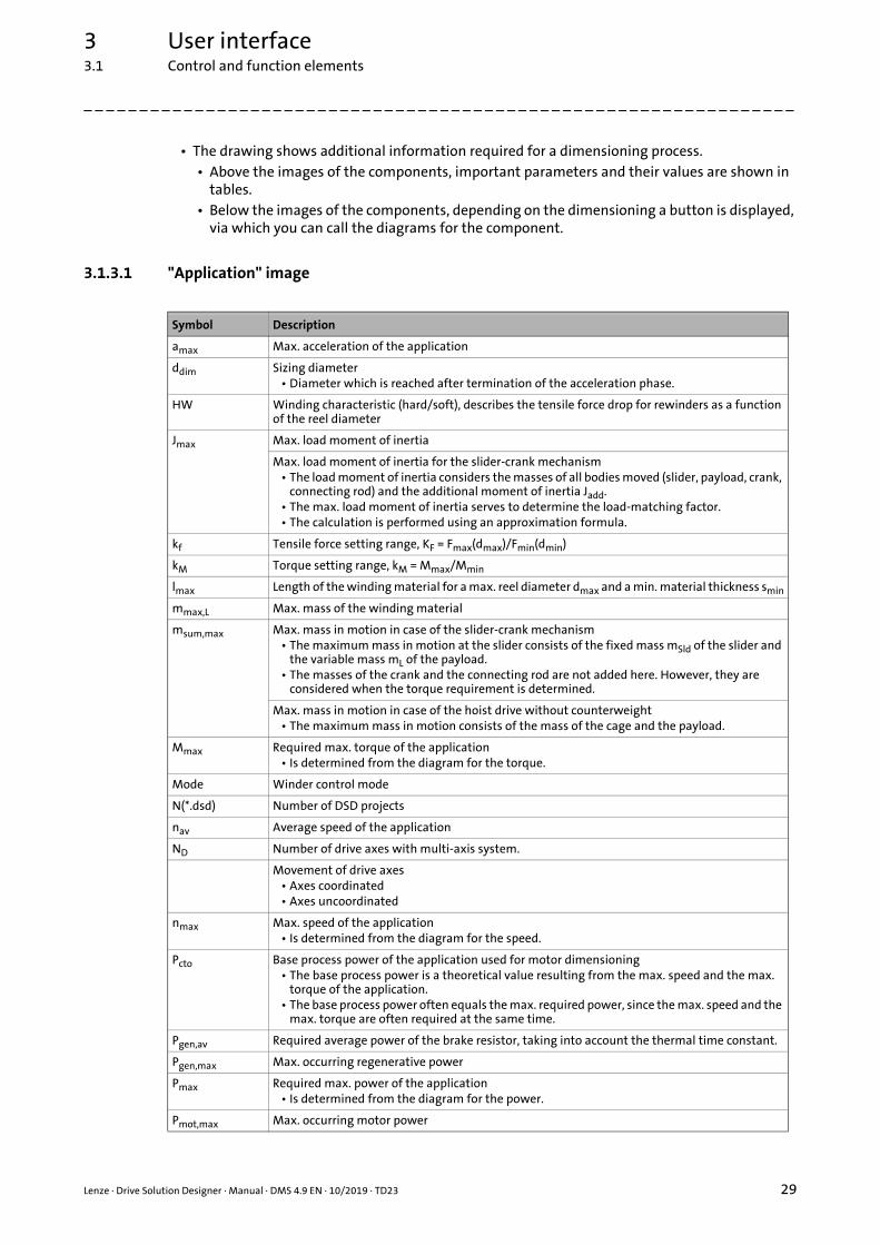
3 User interface3.1 Control and function elements
_ _ _ _ _ _ _ _ _ _ _ _ _ _ _ _ _ _ _ _ _ _ _ _ _ _ _ _ _ _ _ _ _ _ _ _ _ _ _ _ _ _ _ _ _ _ _ _ _ _ _ _ _ _ _ _ _ _ _ _ _ _ _ _
• The drawing shows additional information required for a dimensioning process.• Above the images of the components, important parameters and their values are shown in
tables.• Below the images of the components, depending on the dimensioning a button is displayed,
via which you can call the diagrams for the component.
3.1.3.1 "Application" image
Symbol Description
amax Max. acceleration of the application
ddim Sizing diameter• Diameter which is reached after termination of the acceleration phase.
HW Winding characteristic (hard/soft), describes the tensile force drop for rewinders as a function of the reel diameter
Jmax Max. load moment of inertia
Max. load moment of inertia for the slider-crank mechanism• The load moment of inertia considers the masses of all bodies moved (slider, payload, crank,
connecting rod) and the additional moment of inertia Jadd.• The max. load moment of inertia serves to determine the load-matching factor.• The calculation is performed using an approximation formula.
kf Tensile force setting range, KF = Fmax(dmax)/Fmin(dmin)
kM Torque setting range, kM = Mmax/Mmin
lmax Length of the winding material for a max. reel diameter dmax and a min. material thickness smin
mmax,L Max. mass of the winding material
msum,max Max. mass in motion in case of the slider-crank mechanism• The maximum mass in motion at the slider consists of the fixed mass mSld of the slider and
the variable mass mL of the payload.• The masses of the crank and the connecting rod are not added here. However, they are
considered when the torque requirement is determined.
Max. mass in motion in case of the hoist drive without counterweight• The maximum mass in motion consists of the mass of the cage and the payload.
Mmax Required max. torque of the application• Is determined from the diagram for the torque.
Mode Winder control mode
N(*.dsd) Number of DSD projects
nav Average speed of the application
ND Number of drive axes with multi-axis system.
Movement of drive axes• Axes coordinated• Axes uncoordinated
nmax Max. speed of the application• Is determined from the diagram for the speed.
Pcto Base process power of the application used for motor dimensioning• The base process power is a theoretical value resulting from the max. speed and the max.
torque of the application.• The base process power often equals the max. required power, since the max. speed and the
max. torque are often required at the same time.
Pgen,av Required average power of the brake resistor, taking into account the thermal time constant.
Pgen,max Max. occurring regenerative power
Pmax Required max. power of the application• Is determined from the diagram for the power.
Pmot,max Max. occurring motor power
Lenze · Drive Solution Designer · Manual · DMS 4.9 EN · 10/2019 · TD23 29

3 User interface3.1 Control and function elements
_ _ _ _ _ _ _ _ _ _ _ _ _ _ _ _ _ _ _ _ _ _ _ _ _ _ _ _ _ _ _ _ _ _ _ _ _ _ _ _ _ _ _ _ _ _ _ _ _ _ _ _ _ _ _ _ _ _ _ _ _ _ _ _
3.1.3.2 "Gearbox" image
Pmot,av Average power (mean value)
Prms,cto Required thermal power of the motor
qdim Dimensioning winding ratio, qdim = dmax/dmin
qmax Max. winding ratio, qmax = dmax/dmin
s Path/distance of the slider with the slider-crank mechanism• The distance covered by the slider and the payload starts from zero at the beginning of the
motion cycle.
tCrd Coordinated cycle time
Symbol Description
Symbol Description
A(Meq) Ratio of the equivalent torque to the max. permissible torque:Meq / Mmax,per,G
A(Min,max) Clutch utilisation with reference to the max. drive torque• For flange mounting only
A(Mmax) Ratio of the max. torque of the application to the max. permissible torque of the gearbox:Mmax / Mmax,per,G
A(nmax) Max. occurring speed relative to the max. speed of the gearbox:nmax / nmax,G
Ath,1,G(nth) Utilisation of the gearbox relative to the thermal output speed
A(T) Utilisation of the gearbox relative to the fatique strength• If the value is > 100 %, an exact check is required.
Type Direct or standard mounting of the motor on the Lenze gearbox
ireq Required ratio (Lenze gearbox and additional drive element if required)• Is calculated from the intended input speed of the gearbox, relative to the max. speed of the
application:nin / nmax
• Ratio ireq is required to operate the motor with the field weakening factor specified by DSD.
i2,req Required ratio of the additional drive element under consideration of a Lenze gearbox, if any• Is calculated from the intended input speed, relative to the max. speed of the application:
nin / nmax• Ratio ireq is required to operate the motor with the field weakening factor specified by DSD.
iact,G Actual ratio of the Lenze gearbox
iact,K Actual ratio of the additional drive element
Jout,K Moment of inertia at the output end of the additional drive element
kG Correction factor for the torque of the gearbox
Mper,out Permissible output torque without speed evaluation.
Meq Equivalent output torque of the Lenze gearbox• Is calculated from the diagram for the torque of the application.
KEfficiency of the additional drive element at the rated point
nin,max Max. input speed of the Lenze gearbox• Is determined from the M-n diagram of the Lenze gearbox
nout,max Max. speed at the output shaft
nper,in,max Max. permissible input speed of the Lenze gearbox
nper,th,out Permissible thermal output speed of the gearbox
30 Lenze · Drive Solution Designer · Manual · DMS 4.9 EN · 10/2019 · TD23

3 User interface3.1 Control and function elements
_ _ _ _ _ _ _ _ _ _ _ _ _ _ _ _ _ _ _ _ _ _ _ _ _ _ _ _ _ _ _ _ _ _ _ _ _ _ _ _ _ _ _ _ _ _ _ _ _ _ _ _ _ _ _ _ _ _ _ _ _ _ _ _
3.1.3.3 "Motor" image
3.1.3.4 "Inverter" image
Symbol Description
PN Rated power of the motor
nrated Rated speed of the motor
Mrated Rated torque of the motor
Mdyn,M Maximum torque in air gap
IN Rated motor current
Ath,max Max. thermal utilisation of the motor
A(Mmax) Utilisation of the motor relative to the torque• Ratio of the max. required torque to the max. possible torque of the motor during operation
on the selected inverter and with the selected control mode:Mmax,req / Mmax,M
A(Mrms) Utilisation of the motor with reference to the effective torque and taking into account the thermal time constant
A(Mdyn,M) Dynamic utilisation of the motor• Ratio of the max. occurring motor torque to the rated motor torque:
(Mmax / MN)
A(M0’) Utilisation of the synchronous motor, taking an unfavourable rotor position with a load at a standstill into consideration (thermal standstill utilisation)
kf Field weakening factor of the motor
kJ,max Load-matching factor of the motor
Symbol Description
A(Imax / Irated,M) Utilisation of the inverter• Ratio of the max. output current of the inverter (Imax) to the rated motor current (IN,M).• If the inverter is highly overdimensioned with regard to the motor, the control quality
decreases.
A(Iimp,max) Thermal utilisation of the inverter relative to the power pulse current for 1 s or 60 s
A(Ired,max) Utilisation of the inverter relative to the reduced max. output current
Ath,Brm Thermal utilisation of the internal brake transistor
ABrm(ED) Utilisation of the internal brake transistor, relative to the i×t monitoring
Amax Max. utilisation of the brake resistor
Ath Thermal utilisation of the brake resistor
Ath,max Max. thermal utilisation of the inverter relative to the reduced output current
Imax Max. output current of the inverter selected
IN Rated current of the inverter selected
PN Rated motor power of the inverter selected
Type Type of brake resistor
Lenze · Drive Solution Designer · Manual · DMS 4.9 EN · 10/2019 · TD23 31

3 User interface3.1 Control and function elements
_ _ _ _ _ _ _ _ _ _ _ _ _ _ _ _ _ _ _ _ _ _ _ _ _ _ _ _ _ _ _ _ _ _ _ _ _ _ _ _ _ _ _ _ _ _ _ _ _ _ _ _ _ _ _ _ _ _ _ _ _ _ _ _
3.1.3.5 Image "Power supply module" or "Regenerative power supply module"
3.1.3.6 "Supply network" image
The displayed quantities always refer to the supplying mains (AC mains or DC mains). In case ofmulti-axis controllers that are connected via a power supply module or a regenerative power supplymodule, the values of the power supply unit are indicated.
Symbol Description
ABrm(ED) Utilisation of the internal brake transistor, relative to the i×t monitoring
ABrm(Pmax) Utilisation of the brake transistor, relative to the max. power
Amax,Rb Max. utilisation of the brake resistor
ASup(Pimp,DC) Utilisation of the power supply module, relative to the pulse power in the DC bus.
ASup(Pmax) Utilisation of the power supply module, relative to the max. power.
ASup(Pgen,max) Utilisation of the regenerative power supply module without brake transistor, relative to the max. regenerative power
ASup,Brm(Pgen,max) Utilisation of the regenerative power supply module with brake transistor, relative to the max. regenerative power
Ath,Brm Thermal utilisation of the brake transistor
Ath,Rb Thermal utilisation of the brake resistor
Ath,Sup Thermal utilisation of the power supply module
Pgen,cto Regenerative power from which a brake resistor is used additionally
Pgen,max Max. permissible regenerative power
Pgen,N Rated power in generator mode
Pmax(1) Max. permissible power, relative to the 5-s cycle• 0.5 s overload / 4.5 s load removal with 75 % of the continuous rated quantity
Pmax(2) Max. permissible power, relative to the 3-s cycle• 60 s overload / 120 s load removal with 75 % of the continuous rated quantity
Prated Rated horsepower
Type Type of brake resistor
Symbol Description
U Rated mains voltage of the supplying electrical network
Nphs Number of phases of the supplying electrical network
f Mains frequency of the supplying electrical network
Power system Power system of the supplying three-phase system
32 Lenze · Drive Solution Designer · Manual · DMS 4.9 EN · 10/2019 · TD23

3 User interface3.1 Control and function elements
_ _ _ _ _ _ _ _ _ _ _ _ _ _ _ _ _ _ _ _ _ _ _ _ _ _ _ _ _ _ _ _ _ _ _ _ _ _ _ _ _ _ _ _ _ _ _ _ _ _ _ _ _ _ _ _ _ _ _ _ _ _ _ _
3.1.4 Navigation tree and result tree
Below the drawing on the left the Navigation tree or the Result tree is displayed.
• Via the two registers below the Navigation tree or Result tree you can switch between the two views anytime.
3.1.4.1 Navigation tree
The Navigation tree indicates your position within the dimensioning process:
• A green tick indicates all the dimensioning steps that have been edited.
• The steps still to be edited are indicated by a question mark.
• The current step is marked by a red arrow.
• The context menu (select dimensioning step and click the right mouse button) serves to execute the following commands:• Creating an alternative ( 55) • Create note and delete note.Notes ( 37)
• The dimensioning steps marked with contain notes.• A mouse-click on the icon opens the note.
Tip!
In the Navigation tree you can also select dimensioning steps that have been previouslyedited and change to the corresponding input template.
Lenze · Drive Solution Designer · Manual · DMS 4.9 EN · 10/2019 · TD23 33

3 User interface3.1 Control and function elements
_ _ _ _ _ _ _ _ _ _ _ _ _ _ _ _ _ _ _ _ _ _ _ _ _ _ _ _ _ _ _ _ _ _ _ _ _ _ _ _ _ _ _ _ _ _ _ _ _ _ _ _ _ _ _ _ _ _ _ _ _ _ _ _
3.1.4.2 Result tree
The Result tree shows the logic structure of the drive train.
• All components of a drive train are visualised with regard to their interconnection via the Result tree.
• If a component is not clearly selected yet, e.g. if three different motors are still possible, the value range of the parameter is displayed.
3.1.5 Input area
In the input area, you enter the parameters for drive dimensioning.
• A dimensioning process is dynamically: depending on the selection made in a dimensioning step, it may change.
• The representation of the input area depends on the dimensioning step.• Depending on the task, the input fields, selection fields, the MotionDesigner, selection tables
appear with or without curve diagrams and decision fields.
Legend Information
Representation in table form of quantities of the application and of rated quantities and calculated values of the components.
Diagrams of entered and calculated values as well as rated quantities for evaluating the drive task (application), components and energy efficiency.
34 Lenze · Drive Solution Designer · Manual · DMS 4.9 EN · 10/2019 · TD23

3 User interface3.1 Control and function elements
_ _ _ _ _ _ _ _ _ _ _ _ _ _ _ _ _ _ _ _ _ _ _ _ _ _ _ _ _ _ _ _ _ _ _ _ _ _ _ _ _ _ _ _ _ _ _ _ _ _ _ _ _ _ _ _ _ _ _ _ _ _ _ _
3.1.5.1 Structure of the selection tables
Description
Number of results:• Possible: Total results detected by DSD.• Visible: Results proposed and displayed by DSD.
Preview value• A cell with a grey background signalises that the corresponding parameter is a preview value which can
cause a warning signal.
Drive dimensioning messages.• Several messages can be available for one component.• The left column always shows the symbol of the highest warning level.
Warning• Important criteria (e.g. limit values) are not fulfilled. A red background indicates the
corresponding value.• If an utilisation value 1000 is shown, the value is outside the calculable range. The component
cannot be used.
Note• Important information has to be observed for a correct function of the component. A blue
background indicates the corresponding value.
Tip• Tips contain useful information on optimisation. A yellow background indicates the
corresponding value.
Button for resetting the extended representation of the selection table.
Button to show more components with smaller performance values.
Show all possible values detected by DSD.
Button to show more components with higher performance values.
Lenze · Drive Solution Designer · Manual · DMS 4.9 EN · 10/2019 · TD23 35

3 User interface3.1 Control and function elements
_ _ _ _ _ _ _ _ _ _ _ _ _ _ _ _ _ _ _ _ _ _ _ _ _ _ _ _ _ _ _ _ _ _ _ _ _ _ _ _ _ _ _ _ _ _ _ _ _ _ _ _ _ _ _ _ _ _ _ _ _ _ _ _
3.1.5.2 Sorting and filtering results in selection tables
Sorting results
Sorting by alphanumeric characters is possible. Up to three columns can be included. Table columnsthat contain symbols cannot be sorted.
How to sort the results:
1. Click the desired column header .• The result list is sorted according to the data in the selected table column.
• Sorting of the data sets in ascending order.
• Sorting of the data sets in descending order.
2. Keep the <Ctrl> key pressed and click another column header with the mouse to include another column in the sorting.
Filtering results
• The available filters provide comfortable assistance in selecting specific data sets.
How to filter results:
1. Click the desired button in the header.• A selection menu opens.
2. Select filter or filter function.
Filter or filter function
Selection menu Description
Display all Reset all filters of the table column.
User-defined When the user-defined filter is selected, a dialog box opens in which three specific filters can be set.
Identical value • Select a value to indicate only the data sets with this value.
Value range • Select min. and max. value to indicate only the data sets within this value range.
Several values • Select several values to indicate only the data sets with these values.
Alphanumeric characters
The selection menu lists all alphanumeric values of the table column.• Select a value to indicate only the data sets with this value.
36 Lenze · Drive Solution Designer · Manual · DMS 4.9 EN · 10/2019 · TD23

3 User interface3.1 Control and function elements
_ _ _ _ _ _ _ _ _ _ _ _ _ _ _ _ _ _ _ _ _ _ _ _ _ _ _ _ _ _ _ _ _ _ _ _ _ _ _ _ _ _ _ _ _ _ _ _ _ _ _ _ _ _ _ _ _ _ _ _ _ _ _ _
3.1.5.3 Changing a value or a selection subsequently
How to change a value or a selection subsequently:
1. Select the desired dimensioning step in the navigation tree.
2. Change the value or the selection in the input area.
3. Press OK.• You get a confirmation prompt whether the change is to be accepted.
4. Confirm with Yes to accept the change.• The following, already executed dimensioning steps are deleted.• The dimensioning process is continued after the changed dimensioning step.
5. Or press No to cancel the executed changes.
3.1.5.4 Changing interdependent values
Many dimension-specific parameters/components are interdependent. DSD takes these internaldependencies into consideration and waits for a decision in the case of any changes made.
3.1.6 Notes
Each dimensioning step can be provided with a notepad for comments and notes. The notes can beoutput in the protocol.
Lenze · Drive Solution Designer · Manual · DMS 4.9 EN · 10/2019 · TD23 37
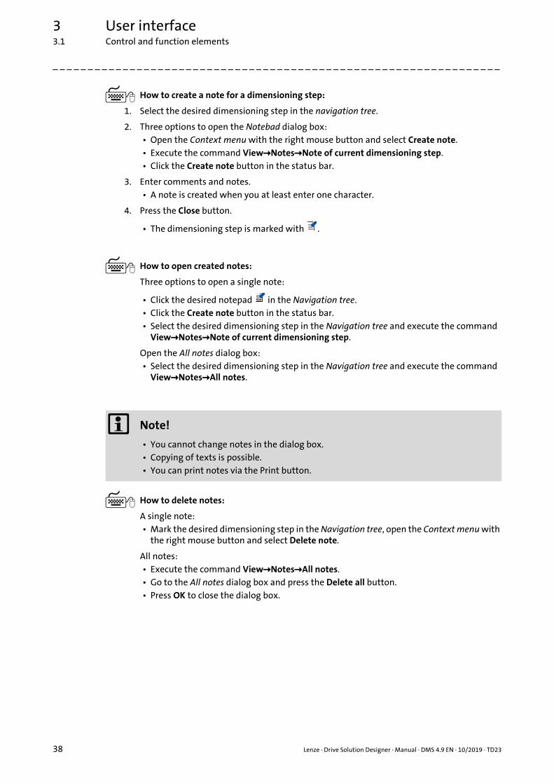
3 User interface3.1 Control and function elements
_ _ _ _ _ _ _ _ _ _ _ _ _ _ _ _ _ _ _ _ _ _ _ _ _ _ _ _ _ _ _ _ _ _ _ _ _ _ _ _ _ _ _ _ _ _ _ _ _ _ _ _ _ _ _ _ _ _ _ _ _ _ _ _
How to create a note for a dimensioning step:
1. Select the desired dimensioning step in the navigation tree.
2. Three options to open the Notebad dialog box:• Open the Context menu with the right mouse button and select Create note.• Execute the command ViewNotesNote of current dimensioning step.• Click the Create note button in the status bar.
3. Enter comments and notes.• A note is created when you at least enter one character.
4. Press the Close button.
• The dimensioning step is marked with .
How to open created notes:
Three options to open a single note:
• Click the desired notepad in the Navigation tree.• Click the Create note button in the status bar.• Select the desired dimensioning step in the Navigation tree and execute the command
ViewNotesNote of current dimensioning step.
Open the All notes dialog box:• Select the desired dimensioning step in the Navigation tree and execute the command
ViewNotesAll notes.
How to delete notes:
A single note:• Mark the desired dimensioning step in the Navigation tree, open the Context menu with
the right mouse button and select Delete note.
All notes:• Execute the command ViewNotesAll notes.• Go to the All notes dialog box and press the Delete all button.• Press OK to close the dialog box.
Note!
• You cannot change notes in the dialog box.• Copying of texts is possible.• You can print notes via the Print button.
38 Lenze · Drive Solution Designer · Manual · DMS 4.9 EN · 10/2019 · TD23

3 User interface3.2 Shortcuts
_ _ _ _ _ _ _ _ _ _ _ _ _ _ _ _ _ _ _ _ _ _ _ _ _ _ _ _ _ _ _ _ _ _ _ _ _ _ _ _ _ _ _ _ _ _ _ _ _ _ _ _ _ _ _ _ _ _ _ _ _ _ _ _
3.2 Shortcuts
In order to use the DSD easier via keyboard, some functions can be accessed via shortcuts.
In order to use the MotionDesigner easier via keyboard, some functions can be accessed viashortcuts. ( 241)
Keyboard command Function
<Alt>+<F4> Exit DSD.
<Alt>+<G> Gearbox calculator ( 472)
<Alt>+<M> Mass calculator ( 467)
<Alt>+<T> Inertial calculator ( 469)
<Esc> Cancel current action.
<F1> Call the "Help" menu.
<Ctrl>+<C> Copy the highlighted element into the clipboard.
<Ctrl>+<N> Create new project ( 48)
<Ctrl>+<O> Open project ( 50)
<Ctrl>+<S> Saving the project ( 52)
<Ctrl>+<V> Paste the element from the clipboard.• Only numerical values can be entered into input fields.
<Ctrl>+<X> Exit DSD.
<Ctrl>+<Tab> Change between multiple opened projects.
<Tab> Skip to the next control element (input field, button, etc.) within the dialog box.
Keyboard command Function
<Del> Delete highlighted element.• The element is deleted permanently.
<Shift>+<Click> In order to highlight several elements keep the <Shift> button pressed and left-click the elements.
<Ctrl>+<A> Highlights all elements on the drawing area.
<Ctrl>+<C> Copy the highlighted element into the clipboard.Processing functions ( 245)
<Ctrl>+<G> Shows or hides the grid of the drawing area.
<Ctrl>+<Click> Duplicates an element in the drawing area when the element is left-clicked while the Ctrl key is pressed.
<Ctrl>+<N> Create new motion profile.
<Ctrl>+<O> Load the motion profile ( 250)
<Ctrl>+<S> Save motion profile ( 251)
<Ctrl>+<V> Paste the element from the clipboard.Processing functions ( 245)
<Ctrl>+<X> Cut the highlighted element and drag to the clipboard.Processing functions ( 245)
<Ctrl>+<Y> Redo last undone action.
<Ctrl>+<Z> Undo last action.
Lenze · Drive Solution Designer · Manual · DMS 4.9 EN · 10/2019 · TD23 39

3 User interface3.3 Closing the program
_ _ _ _ _ _ _ _ _ _ _ _ _ _ _ _ _ _ _ _ _ _ _ _ _ _ _ _ _ _ _ _ _ _ _ _ _ _ _ _ _ _ _ _ _ _ _ _ _ _ _ _ _ _ _ _ _ _ _ _ _ _ _ _
3.3 Closing the program
Options to exit the »Drive Solution Designer«:
• Select the command FileExit.
• Click the Window icon in the Title bar.
• Press the shortcut <CTRL>+<X>.
• Click the shortcut <ALT>+<F4>.
Note!
If the program is closed and projects with changes that are not saved yet are still open, you are asked via the Save project dialog box whether you want to save the projects.
Managing projects: Saving the project ( 52)
40 Lenze · Drive Solution Designer · Manual · DMS 4.9 EN · 10/2019 · TD23

4 Setting up the DSD workplace4.1 Settings during installation
_ _ _ _ _ _ _ _ _ _ _ _ _ _ _ _ _ _ _ _ _ _ _ _ _ _ _ _ _ _ _ _ _ _ _ _ _ _ _ _ _ _ _ _ _ _ _ _ _ _ _ _ _ _ _ _ _ _ _ _ _ _ _ _
4 Setting up the DSD workplace
Before starting the work with the »Drive Solution Designer«, please set up your DSD workplace first.
4.1 Settings during installation
During the installation of the DSD, country-specific settings can be changed already:
Select language
• Language of the user interface.
Language selection for the online help
Select the language in which a web link is to be called
• DSD menus Tools and Help contain web links which serve to directly access information provided on the Lenze web page or the Lenze Intranet.
Preferred unit system
• When values are entered, DSD offers the preferred unit system first.
Tip!
The settings can also be changed later in DSD in the menu ExtrasSettings.
4.2 Language
With the command ExtrasSelect language you select the language of the user interface.
• The languages German, English (British), Czech, Danish, English (American), Spanish, French, Italian, Dutch, Russian, Swedish, Chinese (simplified) and Chinese (traditional) are provided.
• The change-over is effected immediately. The DSD does not have to be restarted.
Tip!
By means of the language switch you can create a project in your native language and thenprint the Log in another language.
Lenze · Drive Solution Designer · Manual · DMS 4.9 EN · 10/2019 · TD23 41

4 Setting up the DSD workplace4.3 Settings
_ _ _ _ _ _ _ _ _ _ _ _ _ _ _ _ _ _ _ _ _ _ _ _ _ _ _ _ _ _ _ _ _ _ _ _ _ _ _ _ _ _ _ _ _ _ _ _ _ _ _ _ _ _ _ _ _ _ _ _ _ _ _ _
4.3 Settings
By using the command ExtrasSettings, you open the Settings dialog box.
• The Settings dialog box contains different tabs via which you can carry out the basic settings.
• Detailed information on the different tabs can be found in the following subchapters.
• With the buttons in the dialog box below you confirm or reject changes carried out:
4.3.1 "General" register
Button Function
OK Confirm entries and close dialog box.
Cancel Reject entries and close dialog box.
Accept Confirm entries and keep dialog box open for further entries.
Settings Information
Working directory Selection of the directory that is called by default for opening and saving projects.
• Use last path• Defines whether the directory called last is used for opening and saving
projects.
Script Define the font used in the masks
Start-up window • Display start-up window• Define whether the start-up window is to be displayed when starting
the DSD.
Tips for drive sizing • Display tips• Tips contain useful information about optimising settings.
Main memory Reserve main memory (RAM) of the computer for DSD.• The change of the setting requires a restart of the DSD.• As long as DSD is open, the reserved main memory is not available for
other applications.• Generally, the Lenze setting is sufficient.• Reserve more main memory if
• many projects are open at the same time and are to be processed,• a motion profile with a lot of grid points is to be imported into the
project.
42 Lenze · Drive Solution Designer · Manual · DMS 4.9 EN · 10/2019 · TD23

4 Setting up the DSD workplace4.3 Settings
_ _ _ _ _ _ _ _ _ _ _ _ _ _ _ _ _ _ _ _ _ _ _ _ _ _ _ _ _ _ _ _ _ _ _ _ _ _ _ _ _ _ _ _ _ _ _ _ _ _ _ _ _ _ _ _ _ _ _ _ _ _ _ _
4.3.2 "Network connections" register
4.3.3 "Help" tab
4.3.4 "Motion" register
Settings Information
Test of the online connection at the start of DSD
In the Lenze setting, at every program start it is checked whether an Internet connection has been established.
Proxy server Activate Use proxy server for Internet connection if an Internet connection is only possible via a proxy server in your local area network. A proxy acts as a switching centre between your computer and the rest of the Internet.
• Ask your system administrator if you require the data (address, port, user name, password) for accessing the proxy server.
URL for product configuration With an active Internet connection, product options and CAD data are directly provided by the »EASY Product Finder«. The »EASY Product Finder« can be reached at the following Internet address:
• https://productfinder.lenze.com or• https://productfinder.lenze.cn
Under URL for product configuration and URL for CAD data one of the two Internet addresses is preset depending on the installation of the DSD.
Tip!If the »EASY Product Finder« is not available at one of the URLs, you can enter the other URL.
URL for CAD data
Port MotionDesigner This value must only be changed in consultation with the Lenze Support department.
Settings Information
Language Language selection for the online help.Selection of the language on the Lenze web page if a weblink is called.
Settings Information
Digital resolution motion profile The analog motion profile created in the MotionDesigner is decomposed into points for further processing in the DSD and for the export into an ASCII file (digitised).
• Max. resolution [dots]• Max. number of values the motion profile is decomposed into.
• Max. error rate [%]• Relative error frequency, with regard to the max. resolution.
Default values, units Default settings for the graphical and numerical creation of motion profiles/subprofiles.
Flying restart functions Drawing help for the graphical creation of motion profiles/subprofiles. For simple positioning of drawn elements.
Lenze · Drive Solution Designer · Manual · DMS 4.9 EN · 10/2019 · TD23 43

4 Setting up the DSD workplace4.3 Settings
_ _ _ _ _ _ _ _ _ _ _ _ _ _ _ _ _ _ _ _ _ _ _ _ _ _ _ _ _ _ _ _ _ _ _ _ _ _ _ _ _ _ _ _ _ _ _ _ _ _ _ _ _ _ _ _ _ _ _ _ _ _ _ _
4.3.5 "Units" tab
4.3.6 "Protocol" tab
Settings Information
Unit systems Definition of unit systems that are to be available in the input masks.• You can both select the SI unit system or the Imperial unit system.
Preferred unit system Application of the unit system: Imperial or Metric with regard to inputs and outputs.
Preferred units Definition of the units for frequently used physical quantities.
Settings Information
Output format Setting of the output format for the log file:• Word 97-2003 document (*.doc)
• Microsoft Word 97 to Word 2003• Word document (*.docx)
• From Microsoft Word 2007• Portable document format (*.pdf)
• PDF (for reading the file, Adobe Reader is required.
Preferences for the detailed reportSettings for the commissioning data
The two tabs can be used to make separate settings for the detailed protocol and the commissioning data.
Output ofSelection of additional information which is to contain the detailed Log and the commissioning data
• Notes• Notes for single dimensioning steps written by the user.
• Diagrams• Dependent on the settings under Detailed selection diagrams/table of
values.• Tables of values
• Dependent on the settings under Detailed selection diagrams/table of values.
• Product options• Details on Lenze products like motor, brake, gearbox, inverter.
Detailed selection diagrams/tables of valuesSelection of diagrams and tables of values which are to contain the detailed Log and the commissioning data.
• Extensive selection of diagrams and tables of values regarding application, gearbox, motor, inverter, DC bus and energy efficiency on evaluating and analysing the dimensioning.
Lenze settingThe selection of diagrams and tables of values is reset to the Lenze setting.
44 Lenze · Drive Solution Designer · Manual · DMS 4.9 EN · 10/2019 · TD23

4 Setting up the DSD workplace4.3 Settings
_ _ _ _ _ _ _ _ _ _ _ _ _ _ _ _ _ _ _ _ _ _ _ _ _ _ _ _ _ _ _ _ _ _ _ _ _ _ _ _ _ _ _ _ _ _ _ _ _ _ _ _ _ _ _ _ _ _ _ _ _ _ _ _
4.3.7 "Customer data" tab
Customer data are managed in a customer database in the DSD. In the "Project information"dimensioning step you select customer data or create new customers. Via the Export and Importfunctions, you can transfer the customer data to other DSD installations.
4.3.8 "User data" tab
User data
Licence information:
Information regarding the licence that has been entered in the »EASY Navigator«.
• Read only.
Settings Information
Export Export of the complete customer data to an XML file.
Import Import of the XML file with customer data.
Settings Information
Salutation, title Sex, title.
Name Surname of the registered person.
First name First name of the registered person.
Company Company of the registered person.
Department Area of work within the company
E-mail E-Mail address of the registered person.• The automatically generated e-mails are sent to this address.
Function Field of responsibility within the company
Street/house number or PO boxPostcode, town
Postal address of the company.
Country Site (country) of the company.
Phone Telephone number under which the user can be reached.
Fax Telefax number under which the user can be reached.
Language for communication User's language for communication with Lenze for communication via e-mail, telephone, or telefax.
• German• English
Detection of usage data Regular statistical investigation on the use of the DSD for continuous and target-oriented development. Personal data will not be saved or transmitted.
• Acquisition of application data ( 558) • Read the data protection notice at http://www.Lenze.com.
Lenze · Drive Solution Designer · Manual · DMS 4.9 EN · 10/2019 · TD23 45
4 Setting up the DSD workplace4.4 Communication with the Lenze DSD server
_ _ _ _ _ _ _ _ _ _ _ _ _ _ _ _ _ _ _ _ _ _ _ _ _ _ _ _ _ _ _ _ _ _ _ _ _ _ _ _ _ _ _ _ _ _ _ _ _ _ _ _ _ _ _ _ _ _ _ _ _ _ _ _
4.4 Communication with the Lenze DSD server
In the following situations data are generated, which the DSD wants to send to the Lenze DSD serverautomatically:
All data transmitted by the DSD are locally saved to your PC under"C:\Users\Benutzername\AppData\Roaming\Lenze\DSD\V4.x.x.x\user_data\mail" in the "sent"or "outbox" directory.
• If there is an Internet connection, copies of the data transmitted are stored in the "sent" directory.• Read the data protection notice at http://www.Lenze.com.
• If there is no Internet connection, the data to be transmitted are stored in the "outbox" directory.• At the next program start, the DSD will try to send these data again. Delete the files in the
"outbox" directory if the DSD is not to send these data.• When the data have been transmitted successfully, copies of the data transmitted are stored
in the "sent" directory.• Ask your responsible Lenze sales department if you want to send data from the "outbox"
directory to Lenze via e-mail.
4.4.1 Messages
When the data is sent to the DSD server, the following messages are displayed which must beconfirmed by pressing OK.
• If there is an Internet connection:
Reason File type Call
Acquisition of application data
*.zip Every three months automatically or manually by the user.
Hard conflict conflict_xxxxxxxx.dsd Hard conflict in the DSD.• The conflict is definitely indicated automatically
by means of a number combination.
Registration dialog *.xml Only once, during the registration, the information as to when a registration request has already been sent is stored.
Check for updates – Manually or automatically at regular intervals.
Message Meaning
Your message has been sent successfully to the DSD server. A copy of your message is saved under "C:\Users\Benutzername\AppData\Roaming\Lenze\DSD\V4.x.x.x\user_data\mail\sent".
With the transmission two files were stored in the "sent" folder:
1.*.mail: This file was sent.2.*.type: Original source file. This file was saved for
manual use.
The outbox still contains unsent data. The DSD has identified a connection to the Internet and is now sending the files from the "outbox" folder.
46 Lenze · Drive Solution Designer · Manual · DMS 4.9 EN · 10/2019 · TD23
4 Setting up the DSD workplace4.4 Communication with the Lenze DSD server
_ _ _ _ _ _ _ _ _ _ _ _ _ _ _ _ _ _ _ _ _ _ _ _ _ _ _ _ _ _ _ _ _ _ _ _ _ _ _ _ _ _ _ _ _ _ _ _ _ _ _ _ _ _ _ _ _ _ _ _ _ _ _ _
• Ifthere is no Internet connection:
4.4.2 Software updates
4.4.3 Assistance in dealing with problems
DSD cannot send any data to the DSD support although a connection to the Internet has beenestablished:
• Check the setting of your firewall
• Specify a proxy server in DSD if a proxy server is used in your local area network.Settings ( 42) "Network connections" register ( 43)
• Consult your system administrator.
Message Meaning
Connection to the DSD server could not be established.The data are saved under"C:\Users\Benutzername\AppData\Roaming\Lenze\DSD\V4.0.0.4\user_data\mail\outbox".When the DSD is started for the next time with a faultless online connection, this data is sent.
The files could not be sent. They are saved in the "outbox" folder until they can be transmitted successfully.
1.*.mail: This file is transmitted when an online connection has been established.
2.*.type: Original source file. This file was saved for manual use.
Message Meaning
The DSD version is up-to-date. There are no new software updates for the DSD on the DSD server.
An up-to-date version of DSD is available. An update DSD version has been found.Follow the given download link and save the new version on the computer. Close all opened projects and close the DSD. Carry out the update.
No online connection available.It is not possible to search for an update version.
DSD has not detected any connection to the Internet.
Note!
Always keep the »Drive Solution Designer« updated.• Regular software updates correct existing errors.
Lenze · Drive Solution Designer · Manual · DMS 4.9 EN · 10/2019 · TD23 47

5 Managing projects5.1 Create new project
_ _ _ _ _ _ _ _ _ _ _ _ _ _ _ _ _ _ _ _ _ _ _ _ _ _ _ _ _ _ _ _ _ _ _ _ _ _ _ _ _ _ _ _ _ _ _ _ _ _ _ _ _ _ _ _ _ _ _ _ _ _ _ _
5 Managing projects
This chapter deals with the handling of DSD projects.
• When you start the »Drive Solution Designer«, initially no project is loaded and the Start-up window is displayed in the basic setting.
• In the Start-up window you can choose whether you want to create a new project or open a project that is already existing.
5.1 Create new project
How to create a new project:
Select the option Create new project in the Start-up window,
or
click on the icon in the Toolbar, or select the command FileNew.
First the login template for the project information opens, from which the dimensioning with the application selection is continued.
Options in the start-up window
Create new project Create new project
Recently opened projectsRe-open one of the last opened projects offered in the list field.
Open project
Open other projectsOpen an already existing project in the Open project dialog box.
48 Lenze · Drive Solution Designer · Manual · DMS 4.9 EN · 10/2019 · TD23

5 Managing projects5.2 Project information
_ _ _ _ _ _ _ _ _ _ _ _ _ _ _ _ _ _ _ _ _ _ _ _ _ _ _ _ _ _ _ _ _ _ _ _ _ _ _ _ _ _ _ _ _ _ _ _ _ _ _ _ _ _ _ _ _ _ _ _ _ _ _ _
5.2 Project information
The first navigation step, "Project information", serves to record the user data, customer data, andproject data. The data are archived with the project and shown in the log.
Customer data
Customer data contain the data of the recipient of the protocol.
• In order to avoid a repeated specification of the data with regard to a further project for the same customer, customer data is stored in an internal database in the DSD.
• The customer data are saved in a common data structure. They can only be created, altered, deleted, imported, exported, and selected together.
• After entering the data, the respective customer data set can be selected via a selection menu next to the identifier "Customer", "Customer no.", "Contact person".• If a selection from the list has been made, it can be rejected by the 'selection "All" '.
Tip!
The customer data and project data in the "Project information" navigation step can bechanged anytime and their entry is carried out independently of the further configurationsteps.
Edit the desired data and confirm your changes with OK.
Button Function
Import / export customer data Import or export of the customer data (database as a whole)• An export enables the transfer/backup of a user's complete customer
database. This can make sense if the DSD has to be uninstalled or the data are to be provided to a third party.
• An import adopts the data of an external customer database to the DSD, i. e. the existing customer database is completed by the imported customer data.
Remove Delete a data record from the customer database
Change Change a data record in the customer database• If a customer data record is to be changed this can only be effected in a
cohesive manner. The changed data record afterwards is provided for selection.
New entry Create a new data record in the customer database• Additional information can be added via the Change button.
All customers Reset the customer data mask to the initial state.
Lenze · Drive Solution Designer · Manual · DMS 4.9 EN · 10/2019 · TD23 49

5 Managing projects5.3 Open project
_ _ _ _ _ _ _ _ _ _ _ _ _ _ _ _ _ _ _ _ _ _ _ _ _ _ _ _ _ _ _ _ _ _ _ _ _ _ _ _ _ _ _ _ _ _ _ _ _ _ _ _ _ _ _ _ _ _ _ _ _ _ _ _
5.3 Open project
The constant further development of the DSD and update of data may cause a deviation of theproject created with an earlier DSD version from the knowledge and database of the current DSDversion. Thus, when a project is opened, the DSD checks if the project is compatible. In case of anincompatibility, the Compatibility check dialog box opens that shows your the test results andprovides possible processing steps.
How to open a project (*.dsd):
1. Select a procedure to open the project. • Select the corresponding project in the Start dialog in the list field under Recently
opened projects, or select the option Open other projects.
• Click the icon in the Toolbar.• Execute the command FileOpen or press the <Ctrl>+<O> keys.• Select the corresponding project using the command FileRecently opened projects.
2. When the Compatibility check dialog box is displayed, you have the following options depending on the test results:• Import project ( 51) • Open the project in the ProjectViewer ( 52)
Processing options of the project in the Compatibility check dialog box:
1) Due to product updates or optimised dimensioning algorithms, the DSD may not reconstruct the project.
Project Import project Open the project in the ProjectViewer
Created with DSD version 4.x Possible Possible
DSD version 3.x Possible to a limited extent 1) Possible
DSD version 1.x or 2.x Not possible Not possible
With user motor Not possible Possible
Multi-axis application Not possible Possible
50 Lenze · Drive Solution Designer · Manual · DMS 4.9 EN · 10/2019 · TD23

5 Managing projects5.3 Open project
_ _ _ _ _ _ _ _ _ _ _ _ _ _ _ _ _ _ _ _ _ _ _ _ _ _ _ _ _ _ _ _ _ _ _ _ _ _ _ _ _ _ _ _ _ _ _ _ _ _ _ _ _ _ _ _ _ _ _ _ _ _ _ _
5.3.1 Import project
The Compatibility check dialog box is displayed.
How to import a project:
1. Click Import project.• The import process starts and the Import project dialog box is displayed.
2. Follow the instructions in the dialog box.• The project is imported in the sequence of the dimensioning steps.
3. In order to simultaneously display the original project, click Open project in the ProjectViewer.• The ProjectViewer starts in a separate dialog box. You can move the dialog box to display
the import process and the original project next to each other.• The display in the ProjectViewer is automatically synchronised with the progress of the
import process. Thus, required changes of parameters and values can be immediately compared to the settings in the original project.
4. In order to abort the import process, click Cancel.• The Import project dialog box is closed.• The project with the already imported dimensioning steps has been created in the DSD
and can be further processed.
5. After the project has been imported successfully, click Close.• The Import project dialog box is closed.• The project has been created in the DSD.
Note!
During the import, the DSD tries to reconstruct the project. Parameters and values that cannot be reconstructed have to be entered manually.
Comply with the following rules during the import:• Open the original project in the ProjectViewer in order that the original parameters
and values are readily available.• Only select values and parameters that are identical with the original project.
• Consider electrical and mechanical parameters.• In the Import project dialog box, unknown parameters are marked.
• Do not select any alternatives if original parameters or values cannot be set (e.g. a component is not available anymore).• Instead, abort the import process. DSD creates a project with the already imported
dimensioning steps. Now complete the dimensioning of the drive with alternative parameters or values.
Check the imported project:• Compare the protocols of the imported project and the original project with regard to
deviations.• Evaluate deviations to the original project with regard to their dimensioning
relevance. If required, re-dimension the drive system.
Restrictions:• Projects with user motors cannot be imported.• Product options cannot be imported.
Lenze · Drive Solution Designer · Manual · DMS 4.9 EN · 10/2019 · TD23 51

5 Managing projects5.4 Saving the project
_ _ _ _ _ _ _ _ _ _ _ _ _ _ _ _ _ _ _ _ _ _ _ _ _ _ _ _ _ _ _ _ _ _ _ _ _ _ _ _ _ _ _ _ _ _ _ _ _ _ _ _ _ _ _ _ _ _ _ _ _ _ _ _
5.3.2 Open the project in the ProjectViewer
The Compatibility check dialog box is displayed.
How to open a project in the ProjectViewer:
1. Click Open project in the ProjectViewer.• All dimensioning details of the DSD project are displayed.• Navigation tree, result tree and logs are provided as usual.• The motion profile (created in the MotionDesigner) can be saved in a file.• The drive dimensioning cannot be changed.
2. In order to close the ProjectViewer, click on in the dialog box.
5.4 Saving the project
Save opened projects from time to time, in order to protect your work against power failures orsystem problems.
• In the Lenze setting, the Automatic saving is activated to save the project at regular intervals. The function is executed in the background and can be set. Settings ( 42)
• If you open the saved project in the DSD again later on, the dimensioning can be continued from the point of saving.
• You can also skip back to any position in the navigation tree, e.g. to adapt an already available solution for similar requirements.
How to save the current project:
Click the icon in the Toolbar, execute the command FileSave or press the <Ctrl>+<S> keys.• All pieces of information concerning the configured drive solution are saved.• The file receives the extension *.dsd by default.
52 Lenze · Drive Solution Designer · Manual · DMS 4.9 EN · 10/2019 · TD23

6 Drive dimensioning tools6.1 Data collection via checklists
_ _ _ _ _ _ _ _ _ _ _ _ _ _ _ _ _ _ _ _ _ _ _ _ _ _ _ _ _ _ _ _ _ _ _ _ _ _ _ _ _ _ _ _ _ _ _ _ _ _ _ _ _ _ _ _ _ _ _ _ _ _ _ _
6 Drive dimensioning tools
6.1 Data collection via checklists
The parameters of the application are important data without which a dimensioning processcannot be carried out. These parameters are marked in the check list with "*".
• The relevant data (e.g. mass, speed and motion) must be fully available.
• If less important data are missing (e. g. travelling resistances), you can make assumptions. Additionally document this in the dimensioning protocol.
To support the data collection, the DSD contains a checklist for each application, by means of whichyou can collect the data of the application.
• The checklists can be printed.
• The checklists are accessed via the ToolsApplication checklist menu.• A dialog box opens, by means of which you can select the appropriate application via option
fields.• By clicking on Open the corresponding checklist is opened in Word.
• The checklist contains queries concerning the following topics:
Tip!
The data marked with "Optional" are included in the checklist for the sake of completeness,however, they are not absolutely required for the dimensioning.
Dimensioning part Data
Customers and project data Authorised user, customer, project.
Application data General drive; general drive with an import function for application data; rotary table; travelling drive; belt conveyor for unit loads; belt conveyor for bulk material; hoists with and without counterweight; chain conveyor; line drive with single roll or squeegees; pump; fan; linear axes with a stationary belt drive or an omega belt drive that is moved along; roller conveyor; spindle drive; rack drive.
Motion • Operation with predefined motion profile according to operating mode S1, S2, S3 or S6
• Operation with specific motion profile. The motion profile can be created graphically or be imported.• Collect the parameters in tabular form in the check list or make a
sketch.
Electrical supply and ambient conditions
Optional
Miscellaneous Optional (accuracies...)
Motor Optional including third-party motor
Gearbox/ratio Optionally also for " Additional drive element"
Mechanical brake Optional
Inverter Optional
Dissipation of generated power Optional
Feedback Optional
Lenze · Drive Solution Designer · Manual · DMS 4.9 EN · 10/2019 · TD23 53

6 Drive dimensioning tools6.2 Optimising drive solutions
_ _ _ _ _ _ _ _ _ _ _ _ _ _ _ _ _ _ _ _ _ _ _ _ _ _ _ _ _ _ _ _ _ _ _ _ _ _ _ _ _ _ _ _ _ _ _ _ _ _ _ _ _ _ _ _ _ _ _ _ _ _ _ _
6.2 Optimising drive solutions
DSD provides different functions for optimising drive dimensionings and finding a demand-oriented drive solution.
[6-1] Functions for optimising drive dimensionings
Creating alternatives and project comparison
Recommended use
• The drive should be dimensioned with alternative components. The process and motion data remain unchanged.• An alternative to the current drive dimensioning can be created at any position in the
navigation tree.• You can compare the alternatives to the most important key data. The project comparison
can be printed.
Examples
• A drive dimensioning may require several alternatives to make a decision based on technical or commercial considerations.• We recommend several drive dimensioning with different components.• The drive solution should be calculated with different reserves.
Application Tuner
Recommended use
• The drive should be dimensioned with different process and motion data. The components remain unchanged.
54 Lenze · Drive Solution Designer · Manual · DMS 4.9 EN · 10/2019 · TD23

6 Drive dimensioning tools6.2 Optimising drive solutions
_ _ _ _ _ _ _ _ _ _ _ _ _ _ _ _ _ _ _ _ _ _ _ _ _ _ _ _ _ _ _ _ _ _ _ _ _ _ _ _ _ _ _ _ _ _ _ _ _ _ _ _ _ _ _ _ _ _ _ _ _ _ _ _
6.2.1 Creating an alternative
You can create alternatives to existing projects. A copy of the current project to the desireddimensioning step is created with a new file name. By the window technique of the DSD severalprojects can be opened at the same time. The open projects can be arranged via the Windows menu.
There are two possibilities of creating alternatives in DSD:
A. Place the cursor in the desired position in the navigation tree of the current project. Now execute the Create alternative command using the right mouse button. A copy of the current project up to the highlighted dimensioning step is created.
B. Complete the current project. Save it. Place the cursor in the desired position in the navigation tree. With the command FileSave as the project is saved under a new file name up to the dimensioning step highlighted.
Tip!
An alternative can be created from every dimensioning step in the navigation tree. Like thisseveral alternatives can be created.
Lenze · Drive Solution Designer · Manual · DMS 4.9 EN · 10/2019 · TD23 55

6 Drive dimensioning tools6.2 Optimising drive solutions
_ _ _ _ _ _ _ _ _ _ _ _ _ _ _ _ _ _ _ _ _ _ _ _ _ _ _ _ _ _ _ _ _ _ _ _ _ _ _ _ _ _ _ _ _ _ _ _ _ _ _ _ _ _ _ _ _ _ _ _ _ _ _ _
[6-2] Example of dimensioning with alternatives
Identical dimensioning
Alternative dimensioning compared to project/solution 1
Alternative dimensioning compared to project/solution 1 and 2
56 Lenze · Drive Solution Designer · Manual · DMS 4.9 EN · 10/2019 · TD23

6 Drive dimensioning tools6.2 Optimising drive solutions
_ _ _ _ _ _ _ _ _ _ _ _ _ _ _ _ _ _ _ _ _ _ _ _ _ _ _ _ _ _ _ _ _ _ _ _ _ _ _ _ _ _ _ _ _ _ _ _ _ _ _ _ _ _ _ _ _ _ _ _ _ _ _ _
6.2.2 Application Tuner
In the planning phase of a machine, there generally is only one worst-case-scenario or one referencescenario for the requirements of the machine. However, these scenarios are not able to include alloperating statuses of the machine. Often, further requirements must be checked:
• Is the drive able to move an even greater mass?
• Is the drive able to accelerate even faster?
• Is there a need for considering an emergency stop with a short braking time?
• What is the utilisation or energy balance in the partial load operational range?
• What is the impact of different recipes on the drive?
Features of the Application Tuner:
• Change the data of the application and the motion data as well as to observe and optimise the impacts on the drive if need be.
• integrate further possible operating statuses and material recipes into the dimensioning for the reference scenario.
• Create the optimised drive solution as individual DSD project.
• Output a protocol of the optimised drive solution.
• Support of the additional checks required for emergency stop scenarios for winding drives. Checking emergency-off scenarios ( 213)
Change to the Protocol dimensioning step and click the icon to open the Application Tuner.
Lenze · Drive Solution Designer · Manual · DMS 4.9 EN · 10/2019 · TD23 57

6 Drive dimensioning tools6.2 Optimising drive solutions
_ _ _ _ _ _ _ _ _ _ _ _ _ _ _ _ _ _ _ _ _ _ _ _ _ _ _ _ _ _ _ _ _ _ _ _ _ _ _ _ _ _ _ _ _ _ _ _ _ _ _ _ _ _ _ _ _ _ _ _ _ _ _ _
Legend Description
Application data
Original data of the application.• Values cannot be changed.
Original data of the application.• In these input fields, values can be changed.
Changed data of the application.• Changes are accepted when the input field is exited.
Motion design• Click the MotionDesigner button to change the motion data.
Result comparison• The left column shows calculated values of the original application.• The Overview register provides an overview of the most important values.• The Application, Gearbox, Motor and Inverter registers show detailed values.• The Energy costs and Energy comparison registers show calculated values with regard to energy
efficiency.
Newly calculated value.
Newly calculated value which exceeds the limit value.• If the limit value is exceeded, a message with a detailed description is provided.
Button to open diagrams of the application or of the component.
Buttons to open messages of the application or of the component.
Click the black triangle in the Save button to open the selection menu.• Save the newly calculated dimensioning as separate DSD project.• Create a brief or detailed protocol about the newly calculated dimensioning.• Create an Energy Performance Certificate about the newly calculated dimensioning.
Click the Close button to exit the Application Tuner.
58 Lenze · Drive Solution Designer · Manual · DMS 4.9 EN · 10/2019 · TD23
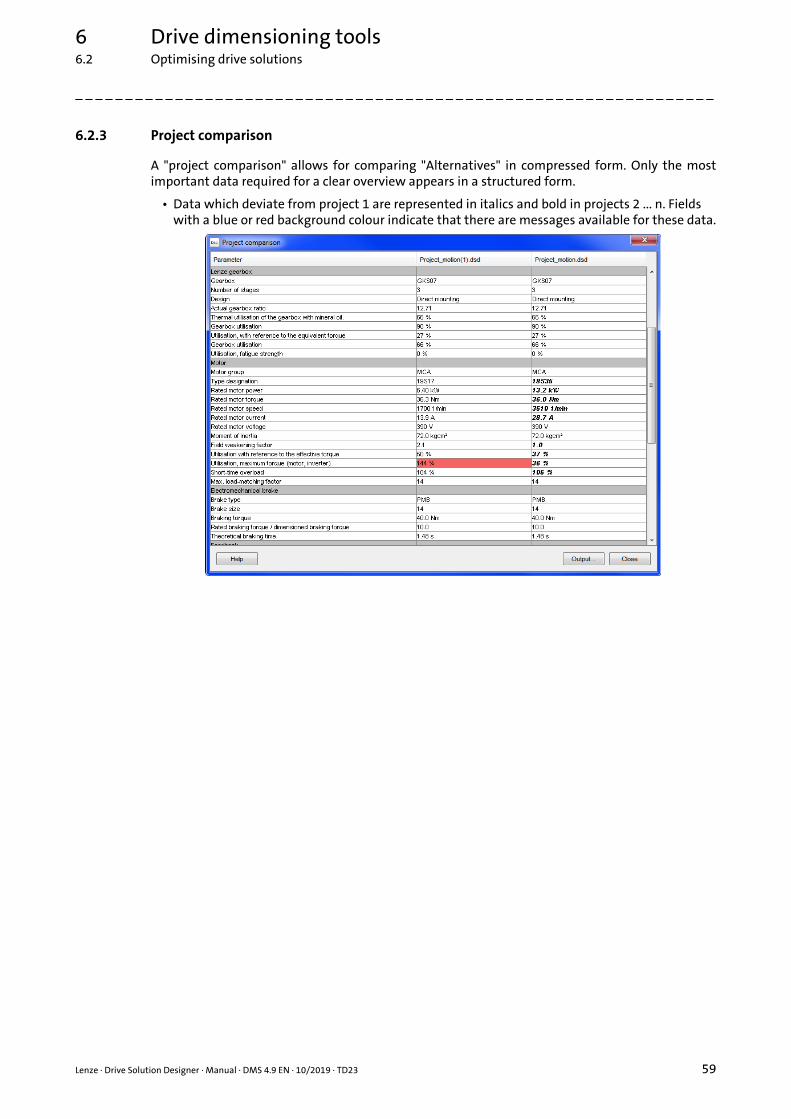
6 Drive dimensioning tools6.2 Optimising drive solutions
_ _ _ _ _ _ _ _ _ _ _ _ _ _ _ _ _ _ _ _ _ _ _ _ _ _ _ _ _ _ _ _ _ _ _ _ _ _ _ _ _ _ _ _ _ _ _ _ _ _ _ _ _ _ _ _ _ _ _ _ _ _ _ _
6.2.3 Project comparison
A "project comparison" allows for comparing "Alternatives" in compressed form. Only the mostimportant data required for a clear overview appears in a structured form.
• Data which deviate from project 1 are represented in italics and bold in projects 2 ... n. Fields with a blue or red background colour indicate that there are messages available for these data.
Lenze · Drive Solution Designer · Manual · DMS 4.9 EN · 10/2019 · TD23 59

6 Drive dimensioning tools6.3 Dimensioning "easily and quickly" or "complex and precisely"
_ _ _ _ _ _ _ _ _ _ _ _ _ _ _ _ _ _ _ _ _ _ _ _ _ _ _ _ _ _ _ _ _ _ _ _ _ _ _ _ _ _ _ _ _ _ _ _ _ _ _ _ _ _ _ _ _ _ _ _ _ _ _ _
6.3 Dimensioning "easily and quickly" or "complex and precisely"
According to the application, the dimensioning process in the DSD can be clearly simplified.
• For an application, always enter the data of the application and describe the motion.
• Calculated utilisation values, diagrams, and options can be output.
For the quick and roughly estimated dimensioning several possibilities are provided. Like this, thenumber of parameters can be reduced, the motion profile presented in a simplified manner, or theproduct options can be left out. By this the amount of processing is considerably reduced for simpledimensioning processes.
If an application is to be optimised, and if dynamic processes play an important role, this can betaken into consideration by accordingly extending the dimensioning. In order to present theproducts in a thorough manner, the options required can also be specified.
In the Input area you carry out the actual entries for the drive dimensioning via the text and listfields:
Name Information
Input area for standard values
The upper half of the input area serves to enter the minimum required values for the application.
Input area for detailed values The lower half of the input area, if required, provides for the entry of detailed values for the application.
• If you activate the option field With detailed values , the display fields change to input fields where you can enter further values for the application.
Option field "With detailed values"
If you activate this option field, the display fields change to input fields where you can enter further values for the application.
Input field By means of the input fields (text fields) in the input area you specify the respective parameter values.
List field(Dropdown list field)
By clicking on the list field, a list in the form of a menu is displayed, allowing for the selection of an entry (here: unit).
Call up auxiliary calculator Via this button you can call up an auxiliary calculator for calculating the value to be entered.Auxiliary calculator ( 464)
Display field Text fields with a grey background only serve to display a value; entering/changing the value is not possible.
• The values in the text fields with a grey background will be considered in the calculation.
• If you activate the option field With detailed values , the display fields change to input fields where you can enter further values for the application.
60 Lenze · Drive Solution Designer · Manual · DMS 4.9 EN · 10/2019 · TD23

6 Drive dimensioning tools6.3 Dimensioning "easily and quickly" or "complex and precisely"
_ _ _ _ _ _ _ _ _ _ _ _ _ _ _ _ _ _ _ _ _ _ _ _ _ _ _ _ _ _ _ _ _ _ _ _ _ _ _ _ _ _ _ _ _ _ _ _ _ _ _ _ _ _ _ _ _ _ _ _ _ _ _ _
6.3.1 Roughly estimated calculation
For a roughly estimated determination of the requirements you can alternatively dimension acontrolled drive with a predefined motion profile according to operating mode.
• The operating modes are scaled loads (VDE 0530) for a drive motor. The operating modes S1 ... S10 are distinguished.Predefined motion profile according to operating mode ( 286)
• If the starting/braking process has no noticeable impact on the machine, often also the operating modes S1, S2, S3, and S6 can be considered for calculation. These operating modes are also provided in the DSD.
6.3.2 Product features
Apart from the component data required for physical dimensioning, there are also importantcharacteristics for mounting, extension, and operation. After dimensioning the drive system youcan individually define the characteristics for each component via the Product featuresdimensioning step.
• For dimensioning a component, product features are not required.
• The dimensioning process can be completed without defining the product features.
• As an alternative, you can define the options in the »EASY Product Finder«.
Lenze · Drive Solution Designer · Manual · DMS 4.9 EN · 10/2019 · TD23 61

6 Drive dimensioning tools6.4 Cost optimisation factors
_ _ _ _ _ _ _ _ _ _ _ _ _ _ _ _ _ _ _ _ _ _ _ _ _ _ _ _ _ _ _ _ _ _ _ _ _ _ _ _ _ _ _ _ _ _ _ _ _ _ _ _ _ _ _ _ _ _ _ _ _ _ _ _
6.4 Cost optimisation factors
Of course, costs are directly associated with the service factors and service durations of theindividual drive components.
• Overdimensionings can render a drive system unattractive very quickly.
• Underdimensionings may make the drive system seem attractive at first. However, high follow-up costs and damage to the company's image can occur if the drive does not perform the tasks required.
Tip!
When carrying out dimensionings, always follow the principle "Not more and not less thanrequired!"
Here the user has to make the best decisions with the help of the wizard in the DSD.
• For this purpose, the following table specifies important decision parameters with regard to costs:
Parameter Effect Notes
Gearbox size Effect on useful life
Torque overload factor of the motor Effect on motor size
Operation at least to the rated motor speed
Effect on motor size and controllability
Otherwise the inverter is not optimally utilised
Load-matching factor KJ Effect on control quality and dynamics
Selection of optimal motion profile Can affect motor size and KJ
Selection of the correct rated motor speed
High rated speed reduces size Observe max. permissible input speed of the gearbox and acoustic emission!
Selection of optimal field weakening factor KF
Has a considerable impact on the size of the inverter, especially in the case of winding drives
Use of 87 Hz operation Reduces the motor size• In the case of winding drives, only
reasonable for a very low winding ratio q
Selection of the switching frequency At 16 kHz only 2/3 of the rated power
Selection of 1-phase inverters at a power of 2.2 kW
Is cheaper than three-phase inverters at the same power
Selection of double-axis modules Servo-Inverter i700
Reduced costs for inverters
DC-bus operation • Reduced mains load• Improved energy efficiency
62 Lenze · Drive Solution Designer · Manual · DMS 4.9 EN · 10/2019 · TD23

7 Applications
_ _ _ _ _ _ _ _ _ _ _ _ _ _ _ _ _ _ _ _ _ _ _ _ _ _ _ _ _ _ _ _ _ _ _ _ _ _ _ _ _ _ _ _ _ _ _ _ _ _ _ _ _ _ _ _ _ _ _ _ _ _ _ _
7 Applications
Currently the DSD contains 21 application models by means of which most of the application casesfor the Lenze drives can be calculated.
In the following chapters each application is described in detail. Apart from a description of theapplication, all displayed parameters, selection tables, and options are explained.
Application data
DSD is able to calculate an application "With detailed values" or "With standard values". Standardvalues serve to carry out quick and approximate dimensioning processes for which not allparameters of the application are known or are to be taken into consideration.
• When it is calculated "With standard values", the input area for detailed values is deactivated. The values in the text fields with a grey background, however, will be considered in the calculation. Input area ( 34)
Alternative dimensioning
The Data of the application dimensioning step serves to quickly create e.g. an alternative "Withdetailed values" dimensioning" from a "With standard values" dimensioning".
• The "Alternative" function serves to create a copy of the current project in each dimensioning step. Creating an alternative ( 55)
Note!
During the dimensioning phase, the DSD can display warnings and notes!• The "Drive sizing messages" chapter contains all warnings and notes with their
possible causes and remedies as well as tips for optimising the dimensioning. ( 503)
Lenze · Drive Solution Designer · Manual · DMS 4.9 EN · 10/2019 · TD23 63

7 Applications7.1 Overview
_ _ _ _ _ _ _ _ _ _ _ _ _ _ _ _ _ _ _ _ _ _ _ _ _ _ _ _ _ _ _ _ _ _ _ _ _ _ _ _ _ _ _ _ _ _ _ _ _ _ _ _ _ _ _ _ _ _ _ _ _ _ _ _
7.1 Overview
Group Application Note
Moving linearly
Belt drive, rotating Also for belt-driven vehicles
Omega belt drive Also for belt-driven vehicles
Rack drive
Spindle drive
Wheel drive Application where operation is effected via the wheels.
Slider-crank mechanism
Eccentric lift table
Move vertically, in a cable-guided manner
Hoist drive without counterweight
Hoist drive with counterweight
64 Lenze · Drive Solution Designer · Manual · DMS 4.9 EN · 10/2019 · TD23

7 Applications7.1 Overview
_ _ _ _ _ _ _ _ _ _ _ _ _ _ _ _ _ _ _ _ _ _ _ _ _ _ _ _ _ _ _ _ _ _ _ _ _ _ _ _ _ _ _ _ _ _ _ _ _ _ _ _ _ _ _ _ _ _ _ _ _ _ _ _
Transporting continuously
Wheel drive Application where operation is effected via the wheels.
Chain conveyor Drive solution is possible with Lenze Smart Motor.Applications using the Lenze Smart Motor ( 71)
Roller conveyor Drive solution is possible with Lenze Smart Motor.Applications using the Lenze Smart Motor ( 71)
Belt conveyor, unit load Drive solution is possible with Lenze Smart Motor.Applications using the Lenze Smart Motor ( 71)
Belt conveyor, bulk material Drive solution is possible with Lenze Smart Motor.Applications using the Lenze Smart Motor ( 71)
Actuate synchronously
Synchronous drive - single roll
Synchronous drive of squeegees
Move,actuate in a rotary
manner
General rotary drive Rotary drive
Rotary table drive Only for horizontal rotary tables
Conveyhydraulically,
pneumatically
Pump
Fan
Importing M-n-operating points
Importing M-n-operating points Import of the operating points for torque and speed from an ASCII file.From the ASCII file additionally the moment of inertia of the application, and the states of controller inhibit and of the brake can be imported.
Group Application Note
Lenze · Drive Solution Designer · Manual · DMS 4.9 EN · 10/2019 · TD23 65

7 Applications7.1 Overview
_ _ _ _ _ _ _ _ _ _ _ _ _ _ _ _ _ _ _ _ _ _ _ _ _ _ _ _ _ _ _ _ _ _ _ _ _ _ _ _ _ _ _ _ _ _ _ _ _ _ _ _ _ _ _ _ _ _ _ _ _ _ _ _
Size the multi-axis system
Size the multi-axis system Combine several DSD projects (drive axes) which are to form a multi-axis grouping and dimension the supply components for this purpose.
Winding materials
Rewinder (single)
Unwinder (single)
Group Application Note
66 Lenze · Drive Solution Designer · Manual · DMS 4.9 EN · 10/2019 · TD23

7 Applications7.2 Basic calculations
_ _ _ _ _ _ _ _ _ _ _ _ _ _ _ _ _ _ _ _ _ _ _ _ _ _ _ _ _ _ _ _ _ _ _ _ _ _ _ _ _ _ _ _ _ _ _ _ _ _ _ _ _ _ _ _ _ _ _ _ _ _ _ _
7.2 Basic calculations
In this chapter the basic calculations required for ascertaining the requirement of the applicationare described. The initial situation results from the calculations which have to be carried out for therespective application (e. g. travelling drive).
The requirement of the application results from
• The torque required,
• The speed required,
• The power resulting from the two.
7.2.1 Torque
To dimension the drive system correctly, the torque of the application is required. It should becalculated completely for the application, taking the losses (e. g. friction) into consideration. Adivision into a dynamic and a stationary component cannot be effected, as the friction partly has aneffect on dynamic components, and to some extent it has not.
For instance, in the case of a spindle, due to the linearly moved masses losses are created withregard to the dynamic forces, and due to the moment of inertia of the spindle the dynamic torquesact on the drive system without losses. Furthermore the losses depend on different factorsdepending on the application. It is therefore assumed that the required torque of the applicationMapp is given:
[7-1] Equation 1: Total torque of the application
Tip!
The equation for calculating the torque can be found in the chapter for the respectiveapplication model.
Basically the total requirement of the torque results from the following.
• The dynamic torque of the application results from the multiplication of the moment of inertia and the angular acceleration:
[7-2] Equation 2: Dynamic torque of the application
• The stationary torque Msds is calculated on the basis of the application-specific equations that are listed in the chapter for the respective application model.
• The total torque of the application results from adding the dynamic and the stationary component:
[7-3] Equation 3: Total torque of the application
Msum Mapp=
Mdyn J =
Msum Mdyn Msds+=
Lenze · Drive Solution Designer · Manual · DMS 4.9 EN · 10/2019 · TD23 67

7 Applications7.2 Basic calculations
_ _ _ _ _ _ _ _ _ _ _ _ _ _ _ _ _ _ _ _ _ _ _ _ _ _ _ _ _ _ _ _ _ _ _ _ _ _ _ _ _ _ _ _ _ _ _ _ _ _ _ _ _ _ _ _ _ _ _ _ _ _ _ _
Calculation of the effective torque of the application:
[7-4] Equation 4: Effective torque of the application
7.2.2 Application performance
Power P of the application in [W] results from multiplying the torque and the angular velocity:
[7-5] Equation 5: Power of the application
The base process power Pcto of the application in [W] results from multiplying the max. torque andthe max. angular velocity:
[7-6] Equation 6: Base process power of the application
The effective base process power Prms,cto of the application in [W] results from multiplying theeffective torque and the max. angular velocity:
[7-7] Equation 7: Effective base process power of the application
Mrms1T--- M
2t td
0
T
=
P Msum Msum n2 60----------- = =
Pcto Mmax max=
Prms,cto Mrms max=
68 Lenze · Drive Solution Designer · Manual · DMS 4.9 EN · 10/2019 · TD23

7 Applications7.2 Basic calculations
_ _ _ _ _ _ _ _ _ _ _ _ _ _ _ _ _ _ _ _ _ _ _ _ _ _ _ _ _ _ _ _ _ _ _ _ _ _ _ _ _ _ _ _ _ _ _ _ _ _ _ _ _ _ _ _ _ _ _ _ _ _ _ _
7.2.3 Motion of the application
For the calculations, the motion must be taken into consideration. A distinction is made betweenthe predefined and the user-definable motion profile.
• User-definable motion profile:• The motion profile is based on the standardised S8 … S10 operating modes according to
VDE 0530.• For calculating the motion profile the parameters at each time have to be calculated.• The maximum values for power, torque, and speed are important reference values for the
calculation of the motion profile.• The motion profile can be created graphically, defined based on numerical values or be
imported.
• Predefined motion profile:• The motion profile is based on the standardised S1 … S7 operating modes according to
VDE 0530.• For the calculation, apart from the stationary status also dynamic processes are taken into
consideration.• The predefined motion profile provides a simple possibility of entering a motion profile with
acceleration, constant travel, deceleration, and standstill.• The settings "Brake at standstill" and "Controller inhibit at standstill" can be selected.• The parameters "Deceleration time", "Starting time", "Cycle time", and "Direction of
movement" can be altered.
[7-8] Clarification of the possible calculations with different specifications
Specification of the parameters and motion
Rotaryn
Msds J
Translatoryv
Fsdsam
Torque calculation
Power calculation
Important values as points of referencePmaxPcto
Prms,cto MmaxnmaxJmax
M Mdyn Msds J Msds+=+=
P M n2 60----------- =
Lenze · Drive Solution Designer · Manual · DMS 4.9 EN · 10/2019 · TD23 69

7 Applications7.2 Basic calculations
_ _ _ _ _ _ _ _ _ _ _ _ _ _ _ _ _ _ _ _ _ _ _ _ _ _ _ _ _ _ _ _ _ _ _ _ _ _ _ _ _ _ _ _ _ _ _ _ _ _ _ _ _ _ _ _ _ _ _ _ _ _ _ _
7.2.4 Symbols used
Symbol Description Dimension unit
a Acceleration m/s2
Fsds Stationary force N
J Moment of inertia of load kgm2
Mdyn Dynamic torque of the application Nm
Mrms Effective torque of the application Nm
msum Total torque of the application Nm
Msds Stationary torque of the application Nm
n Application speed rpm
P Application performance W
r Radius m
s Distance m
t Time s
T Period s
v Speed m/s
Angular acceleration rad/s2
Angle rad
Angular velocity rad/s
70 Lenze · Drive Solution Designer · Manual · DMS 4.9 EN · 10/2019 · TD23

7 Applications7.3 Applications using the Lenze Smart Motor
_ _ _ _ _ _ _ _ _ _ _ _ _ _ _ _ _ _ _ _ _ _ _ _ _ _ _ _ _ _ _ _ _ _ _ _ _ _ _ _ _ _ _ _ _ _ _ _ _ _ _ _ _ _ _ _ _ _ _ _ _ _ _ _
7.3 Applications using the Lenze Smart Motor
Drive solutions using the Lenze Smart Motor are possible in the DSD under certain conditions. Thediagram shows the required settings.
[7-9] The way to the Lenze Smart Motor - required settings
For a drive dimensioning process using the Lenze Smart Motor, selection of the "Import M-noperating points" application in the DSD may be reasonable.
• Advantages:• For instance in the case of a chain conveyor, you can take the breakaway torque into
consideration.• Results of measurements on the application can be compared to the drive dimensioning by
importing the measured data.• You can dimension drives for applications that are not available in the DSD.
• Additional, necessary actions:• The suitability of the motor control for the application has to be checked manually.• Have the data (output speed, direction of rotation, acceleration time, deceleration time)
checked by your Lenze sales partner. In this way it is ensured that the drive solution can be implemented using the Lenze Smart Motor.
Lenze · Drive Solution Designer · Manual · DMS 4.9 EN · 10/2019 · TD23 71

7 Applications7.4 Belt drive, rotating
_ _ _ _ _ _ _ _ _ _ _ _ _ _ _ _ _ _ _ _ _ _ _ _ _ _ _ _ _ _ _ _ _ _ _ _ _ _ _ _ _ _ _ _ _ _ _ _ _ _ _ _ _ _ _ _ _ _ _ _ _ _ _ _
7.4 Belt drive, rotating
The vast majority of positioning systems require linear movements. If a rotating drive is used, therotation of the motor has to be converted into a linear movement. The speeds that can be achieved,and therefore the dynamics of the positioning process and the repeat accuracy, and thus the qualityof the positioning process to a great extent are defined by the mechanics.
Characteristics of a rotating belt drive
• A motor actuates a belt pulley which in turn actuates a toothed belt. The mass to be moved, which usually consists of a tool and the payload, is fastened to the toothed belt.
• Toothed belts allow for a higher speed, but a lower positioning accuracy of approx. 0.1 mm. The positioning path is greater than that for the spindle, but it also is limited.
• Toothed belt drives are very often used in applications for material handling , since they offer a high speed and an accuracy sufficient for this application.
Requirements with regard to a drive system for positioning
• High dynamic performance to achieve short positioning times
• High accuracy, according to the application
• High degree of reliability
72 Lenze · Drive Solution Designer · Manual · DMS 4.9 EN · 10/2019 · TD23

7 Applications7.4 Belt drive, rotating
_ _ _ _ _ _ _ _ _ _ _ _ _ _ _ _ _ _ _ _ _ _ _ _ _ _ _ _ _ _ _ _ _ _ _ _ _ _ _ _ _ _ _ _ _ _ _ _ _ _ _ _ _ _ _ _ _ _ _ _ _ _ _ _
7.4.1 Applications with a horizontal direction of movement
• Application of a rotating belt drive with wheel guide:
• Application of a rotating belt drive with linear guide:
Note!
The losses have a relatively high constant proportion, i. e. the torque loss is almost irrespective of the load torque. The reason for this is the pretension of the belt, which is required if dynamic traversing with a high precision is to be carried out.
The DSD thus considers the efficiency to be entered as a constant torque. For the calculation always an efficiency at the highest load is assumed. Because of this definite dimensioning, no additional constant torque has to be specified.
Lenze · Drive Solution Designer · Manual · DMS 4.9 EN · 10/2019 · TD23 73

7 Applications7.4 Belt drive, rotating
_ _ _ _ _ _ _ _ _ _ _ _ _ _ _ _ _ _ _ _ _ _ _ _ _ _ _ _ _ _ _ _ _ _ _ _ _ _ _ _ _ _ _ _ _ _ _ _ _ _ _ _ _ _ _ _ _ _ _ _ _ _ _ _
7.4.2 Applications with a vertical direction of movement
For this model a tool is positioned by means of a toothed belt. A motor or geared motor with orwithout a downstream speed-transforming gear actuates a toothed belt. The motor is fixedlyconnected to the machine. A tool or payload mL is fastened to the toothed belt. The tool or payloadis operated via guide (coefficient of friction Gdn).
• The positioning process can be carried out via time-controlled path generators (positioning software) or via path-controlled path generators (electronic cams).
• The movement is carried out within one of the three dimensional axes (horizontally x, y, and vertically z), or within a plane inclined to the horizontal by the angle (0 ... 90°).
• For Z axes often an omega arrangement of the belt is selected, because less operating space is required.• An omega arrangement of the belt according to the following schematic diagram with a
fixed motor is also taken into consideration by this DSD model:
Beating of the belt pulley
The toothed belt either is mounted directly to the motor shaft/gearbox shaft, or by means of atransmission gear (internal bearing support):
• In the case of arrangement A the bearing of the motor or gearbox has to be checked separately with regard to radial forces at the output end (see the following section). This function currently is not contained in the DSD yet.
Arrangement A Arrangement B
Belt Belt
M
�F 2 · Frad prl,Blt�
M
�F 0rad �
74 Lenze · Drive Solution Designer · Manual · DMS 4.9 EN · 10/2019 · TD23

7 Applications7.4 Belt drive, rotating
_ _ _ _ _ _ _ _ _ _ _ _ _ _ _ _ _ _ _ _ _ _ _ _ _ _ _ _ _ _ _ _ _ _ _ _ _ _ _ _ _ _ _ _ _ _ _ _ _ _ _ _ _ _ _ _ _ _ _ _ _ _ _ _
Consideration of the radial and axial forces on the bearings in the gearbox and motor
In addition to the torques to be transmitted, considering the radial and axial forces on the rotor isalso important for the selection of the gearbox and motor.
[7-10] Radial and axial forces
• The radial force on the motor/gearbox output shaft can increase up to double the pretension Fprl,Blt of the toothed belt.
• The pretension of the belt depends on the circumferential force FBlt Faux to be transmitted and on the positioning accuracy required and the permissible belt force.
• The pretension of the belt usually is 1 ... 1.2 × FBlt, in individual cases up to 2 × FBlt. This has to be taken into consideration when the motor or gearbox is selected.
• If required, a transmission gear (see arrangement B) or a gearbox with reinforced bearings is to be used.
Note!
This calculation currently cannot be carried out by the DSD.
Axial forces occur if the belt pulley is not in alignment. Avoid a belt pulley that is not in alignment!For these applications the axial forces can normally be disregarded.
Toothed belt
M
�Frad
Fax
Lenze · Drive Solution Designer · Manual · DMS 4.9 EN · 10/2019 · TD23 75

7 Applications7.4 Belt drive, rotating
_ _ _ _ _ _ _ _ _ _ _ _ _ _ _ _ _ _ _ _ _ _ _ _ _ _ _ _ _ _ _ _ _ _ _ _ _ _ _ _ _ _ _ _ _ _ _ _ _ _ _ _ _ _ _ _ _ _ _ _ _ _ _ _
7.4.3 Calculations
For a linear axis with rotating toothed belts according to the drawing, the following applies:
The belt pulley has the following effective diameter, where pCog specifies the belt pitch:
[7-11] Equation 1: Diameter of belt pulley
Conversion of translatory variables into rotary variables
[7-12] Equation 2: Angle
[7-13] Equation 3: Angular velocity
[7-14] Equation 4: Angular acceleration
Forces of the linear motion
First the mass which is to be moved linearly has to be calculated. The payload mL can adopt differentvalues during the travel cycle. The mass of carriage maux is considered separately.
[7-15] Equation 5: Total mass
The friction force F can for instance occur on the guide rails of the slide. The force acts opposite tothe direction of movement and is taken into consideration by the fraction v/|v| in the followingequation, where at v = 0 the force Fis 0. The static friction at standstill is not considered.
[7-16] Equation 6: Friction force
If the friction force F is related to the mass in motion, a specific travelling resistance results, whichcontains all parts depending on the mass:
[7-17] Equation 7: Specific travelling resistance of the application
For vehicles with a wheel guide instead of a linear guide, here the travelling resistance F’ is to beused:
dCog[mm]pCog[mm] NCog
-------------------------------------------=
2000 sdCog-------------------- 2000 s
pCog NCog----------------------------= =
2000 vdCog-------------------- 2000 v
pCog NCog----------------------------= =
2000 adCog-------------------- 2000 a
pCog NCog----------------------------= =
msum mL maux+=
F msum g Gdn cosvv----- =
F’ g Gdn cos =
76 Lenze · Drive Solution Designer · Manual · DMS 4.9 EN · 10/2019 · TD23

7 Applications7.4 Belt drive, rotating
_ _ _ _ _ _ _ _ _ _ _ _ _ _ _ _ _ _ _ _ _ _ _ _ _ _ _ _ _ _ _ _ _ _ _ _ _ _ _ _ _ _ _ _ _ _ _ _ _ _ _ _ _ _ _ _ _ _ _ _ _ _ _ _
[7-18] Equation 8: Specific travelling resistance of the application for vehicles with a wheel guide
Additionally a counterforce Fvs opposite to the positive direction of movement and a component ofthe force due to weight (downhill force) caused by the slope can act. Constant friction forces of theguide rails, which are independent of the mass, have to be taken into consideration with the correctsign in Fvs.
[7-19] Equation 9: Total translatory force
Required torque of the application
The required torque of the application MApp has to be calculated in three steps. First the force thatis transmitted via the toothed belt has to be ascertained.
• The mass mBlt of the toothed belt is considered by the specific mass m’Blt and the length lBlt.
[7-20] Equation 10: Force of the slide
For calculating the torque, the mass inertia of the application is required. It has to be divided intotwo types:
A. An additional mass inertia on the belt pulley of the toothed belt is added to the mass inertia of the belt pulley:
[7-21] Equation 11: Mass inertia on the side of the belt pulley
B. Additional mass inertias that are connected via the toothed belts and rotate at the same speed (e.g. deflection pulleys, belt tighteners), are included in the moment of inertia Jaux of the deflection pulleys:
[7-22] Equation 12: Mass inertia of the deflection pulleys
Now the required torque at the drive can be calculated:
[7-23] Equation 13: Required torque at the drive
The constant torque loss which occurs within the belt is determined under full load from the torqueat the drive with the efficiency in motor mode of the prestressed belt:
F’ g 2 f cos dWhl
---------------------------dBrg Brg
dWhl-------------------------- Gdn+ +
=
Fsum Fvs msum g+ sin=
Faux F’ msumvv----- Fsum+
msum lBlt m’Blt+ + a=
JCog Jn const= Jkk 1=
n
n const=
= =
Jaux Jv const= Ji
dCog
di----------- 2
i 2=
m
v const=
= =
MD
dCog
2000------------- Faux Jaux +=
Lenze · Drive Solution Designer · Manual · DMS 4.9 EN · 10/2019 · TD23 77

7 Applications7.4 Belt drive, rotating
_ _ _ _ _ _ _ _ _ _ _ _ _ _ _ _ _ _ _ _ _ _ _ _ _ _ _ _ _ _ _ _ _ _ _ _ _ _ _ _ _ _ _ _ _ _ _ _ _ _ _ _ _ _ _ _ _ _ _ _ _ _ _ _
[7-24] Equation 14: Constant torque loss
The torque loss depends on the torque MD which is to be transmitted, so that the resulting torqueMApp defining the power of the application is calculated via the following equation.
• The deterioration of the efficiency within operation in generator mode (backward efficiency) is considered during this calculation.
[7-25] Equation 15: Required torque of the application
Tip!
Further equations to complete the calculations required for an application can be found inthe chapter "Basic calculations". ( 67)
Mth1Blt--------- 1– max MD =
MApp MD------- Mth+
JCog +=
78 Lenze · Drive Solution Designer · Manual · DMS 4.9 EN · 10/2019 · TD23

7 Applications7.4 Belt drive, rotating
_ _ _ _ _ _ _ _ _ _ _ _ _ _ _ _ _ _ _ _ _ _ _ _ _ _ _ _ _ _ _ _ _ _ _ _ _ _ _ _ _ _ _ _ _ _ _ _ _ _ _ _ _ _ _ _ _ _ _ _ _ _ _ _
7.4.3.1 Symbols used
Symbol Description Dimension unit
a Acceleration, translatory m/s2
Acceleration, rotary rad/s2
dWhl Wheel diameter for the wheel-guided system mm
dBrg Bearing diameter for the wheel-guided system mm
dCog Belt pulley diameter mm
f Lever arm of the rolling friction for the wheel-guided system mm
F Friction force of the guiding system N
F’ Specific travelling resistance of the application N/kg
Fvs Counterforce N
Fsum Total translatory force N
FBlt Circumferential force at the toothed belt N
Fprl,Blt Preload force at the toothed belt N
Faux Force of slide N
Frad Radial force N
Fax Axial force N
g Gravitational acceleration (g = 9.81 m/s2) m/s2
JCog Moment of inertia of the belt pulley kgm2
Jaux Moment of inertia of the deflection pulleys kgm2
lBlt Length of the toothed belt m
mL Mass of the payload kg
maux Mass of the slide kg
mBlt Mass of toothed belts kg
m’Blt Specific mass of the belt per meter kg/m
msum Total mass of the application kg
Mth,Blt Constant torque loss Nm
MD Torque at the drive Nm
MApp Required torque of the application Nm
pCog Selected toothed belt pitch mm
s Path, translatory m
v Speed, translatory m/s
NCog Number of teeth of the belt pulley
Blt Transmission efficiency of the toothed belt with initial stress and in the operating point
Angle rad
Angle of tilt °
Gdn Coefficient of friction• Wheel flange and lateral friction of the wheel-guided system• Sliding friction of the linear guide
Brg Coefficient of friction for the wheel-guided system
Angular velocity rad/s
Lenze · Drive Solution Designer · Manual · DMS 4.9 EN · 10/2019 · TD23 79

7 Applications7.4 Belt drive, rotating
_ _ _ _ _ _ _ _ _ _ _ _ _ _ _ _ _ _ _ _ _ _ _ _ _ _ _ _ _ _ _ _ _ _ _ _ _ _ _ _ _ _ _ _ _ _ _ _ _ _ _ _ _ _ _ _ _ _ _ _ _ _ _ _
7.4.4 Data for the entry
7.4.4.1 Belt pulley diameter
7.4.4.2 Mass of the slide
7.4.4.3 Angle of tilt
7.4.4.4 Transmission efficiency of toothed belt
7.4.4.5 Mass of toothed belts
Parameter Description
dCog Belt pulley diameter• The belt pulley is mounted at the end of the output shaft of the motor or gearbox.• The diameter can be calculated by the pitch and the number of teeth (in the case of a toothed
belt).• Value can be entered directly or calculated using a diameter calculator.
"Pinion diameter" calculator ( 474)
Parameter Description
maux Mass of carriage• The mass is used in the calculation for the moment of inertia• The mass of the payload is entered when the motion profile is created.• By means of the mass calculator, an alternative value can be calculated.
Mass calculator ( 467)
Parameter Description
Angle of tilt (gradient)• The value can be entered in degrees or as a percentage.
Parameter Description
Blt Efficiency of the toothed belt with initial stress and maximum stationary operating point.• Since the torque loss of a belt is not proportional to its load, i. e. it is not constant throughout
the entire operating range, however, often only one efficiency factor is known, it is assumed that the value applies to maximum steady-state operation. The losses that can be calculated for this, in the worst case occur as a constant torque loss, so that they are taken into consideration in the DSD.
• The losses of the guide can be covered separately with the specific travelling resistance.
Parameter Description
mBlt Mass of the toothed belt• Can be disregarded in most applications; only in the case of a long traverse path the mass
may have a crucial impact.• The mass of the belt is used in the calculation of the inertial moment.• The mass of the payload is entered when the motion profile is created.• The mass can be estimated by means of the mass calculator.
Mass calculator ( 467)
80 Lenze · Drive Solution Designer · Manual · DMS 4.9 EN · 10/2019 · TD23

7 Applications7.4 Belt drive, rotating
_ _ _ _ _ _ _ _ _ _ _ _ _ _ _ _ _ _ _ _ _ _ _ _ _ _ _ _ _ _ _ _ _ _ _ _ _ _ _ _ _ _ _ _ _ _ _ _ _ _ _ _ _ _ _ _ _ _ _ _ _ _ _ _
7.4.4.6 Moment of inertia, deflection pulleys
7.4.4.7 Moment of inertia of belt pulley
7.4.4.8 Specific travelling resistance
7.4.4.9 Speed
7.4.4.10 Mass of the payload
Parameter Description
Jaux Moment of inertia of the deflection pulleys• Can be disregarded in most applications, though in dynamic applications it may have an
impact on the dimensioning.• The moment of inertia is to be entered relative to the driving pulley and has an impact on the
dynamic torque!• The inertial moment can be estimated by means of the inertial calculator.
Inertial calculator ( 469)
Parameter Description
JCog Moment of inertia of the belt pulley• Can be disregarded in most applications, though in dynamic applications it may have an
impact on the dimensioning.• The moment of inertia has an effect on the dynamic torque!• The inertial moment can be estimated by means of the inertial calculator.
Inertial calculator ( 469)
Parameter Description
F’ Specific travelling resistance• Plays a minor role with regard to dynamic applications.• Can be a rolling and a friction resistance.• By means of the auxiliary calculator the travelling resistance can be estimated.
"Travelling resistance" calculator ( 481)
Parameter Description
v Traversing speed• Value is entered in the Motion dimensioning step.
Parameter Description
mL Mass of payload• Value is entered in the Motion dimensioning step.
Lenze · Drive Solution Designer · Manual · DMS 4.9 EN · 10/2019 · TD23 81

7 Applications7.4 Belt drive, rotating
_ _ _ _ _ _ _ _ _ _ _ _ _ _ _ _ _ _ _ _ _ _ _ _ _ _ _ _ _ _ _ _ _ _ _ _ _ _ _ _ _ _ _ _ _ _ _ _ _ _ _ _ _ _ _ _ _ _ _ _ _ _ _ _
7.4.4.11 Tensile force at the slide (counterforce)
Tip!
By means of the auxiliary calculator you can calculate the travelling resistance of wheel-guided drives and linear guides.
Parameter Description
Fvs Force that works against the direction of movement.• Value is entered in the Motion dimensioning step.
The sign of the counterforce determines its effective direction:• If the speed is positive,
• positive values act opposite to the direction of travel• negative values act with the direction of travel.
• If the speed is negative,• positive values act with the direction of travel• negative values act opposite to the direction of travel.
Note!
If the force acts in a supporting manner, the opposite sign is to be entered.
82 Lenze · Drive Solution Designer · Manual · DMS 4.9 EN · 10/2019 · TD23

7 Applications7.5 Omega belt drive
_ _ _ _ _ _ _ _ _ _ _ _ _ _ _ _ _ _ _ _ _ _ _ _ _ _ _ _ _ _ _ _ _ _ _ _ _ _ _ _ _ _ _ _ _ _ _ _ _ _ _ _ _ _ _ _ _ _ _ _ _ _ _ _
7.5 Omega belt drive
The vast majority of positioning systems require linear movements. If a rotating drive is used, therotation of the motor has to be converted into a linear movement. The speeds that can be achieved,and therefore the dynamics of the positioning process and the repeat accuracy, and thus the qualityof the positioning process to a great extent are defined by the mechanics.
Characteristics of an omega belt drive
• A motor actuates a belt pulley which in turn actuates a belt or a toothed belt. The mass to be moved, which usually consists of the drive, a tool, and the payload, is fastened to the toothed belt.
• Toothed belts allow for a higher speed, but a lower positioning accuracy of approx. 0.1 mm. The positioning path is greater than that for the spindle, but it also is limited.
• Belt drives are very often used in applications for material handling , since they offer a high speed and an accuracy sufficient for this application .
Requirements with regard to a drive system for positioning
• High dynamic performance to achieve short positioning times,
• High accuracy, according to the application
• High degree of reliability
Lenze · Drive Solution Designer · Manual · DMS 4.9 EN · 10/2019 · TD23 83

7 Applications7.5 Omega belt drive
_ _ _ _ _ _ _ _ _ _ _ _ _ _ _ _ _ _ _ _ _ _ _ _ _ _ _ _ _ _ _ _ _ _ _ _ _ _ _ _ _ _ _ _ _ _ _ _ _ _ _ _ _ _ _ _ _ _ _ _ _ _ _ _
7.5.1 Applications with a horizontal direction of movement
• Application of an omega belt drive with wheel guide:
• Application of an omega belt drive with linear guide:
Note!
The losses have a relatively high constant proportion, i. e. the torque loss is almost irrespective of the load torque. The reason for this is the pretension of the belt, which is required if dynamic traversing with a high precision is to be carried out.
The application model thus considers the efficiency to be entered as a constant torque. For the calculation always an efficiency at the highest load is assumed. Because of this definite dimensioning, no additional constant torque has to be specified.
84 Lenze · Drive Solution Designer · Manual · DMS 4.9 EN · 10/2019 · TD23

7 Applications7.5 Omega belt drive
_ _ _ _ _ _ _ _ _ _ _ _ _ _ _ _ _ _ _ _ _ _ _ _ _ _ _ _ _ _ _ _ _ _ _ _ _ _ _ _ _ _ _ _ _ _ _ _ _ _ _ _ _ _ _ _ _ _ _ _ _ _ _ _
7.5.2 Applications with a vertical direction of movement
For this model a tool is positioned by means of a toothed belt. A motor or geared motor with orwithout a downstream speed-transforming gear travels along a fixedly clamped toothed belt. A toolor payload mL is fastened to the motor. The drive is operated via guide (coefficient of friction Gdn).
• The positioning process can be carried out via time-controlled path generators (positioning software) or via path-controlled path generators (electronic cams).
• The movement is carried out within one of the three dimensional axes (horizontally x, y, and vertically z), or within a plane inclined to the horizontal by the angle (0 ... 90°).
Beating of the belt pulley
The toothed belt either is mounted directly to the motor shaft/gearbox shaft, or by means of atransmission gear (internal bearing support):
• In the case of arrangement A the bearing of the motor or gearbox has to be checked separately with regard to radial forces at the output end (see the following section). This function currently is not contained in the DSD yet.
Arrangement A Arrangement B
Belt Belt
M
�F 2 · Frad prl,Blt�
M
�F 0rad �
Lenze · Drive Solution Designer · Manual · DMS 4.9 EN · 10/2019 · TD23 85

7 Applications7.5 Omega belt drive
_ _ _ _ _ _ _ _ _ _ _ _ _ _ _ _ _ _ _ _ _ _ _ _ _ _ _ _ _ _ _ _ _ _ _ _ _ _ _ _ _ _ _ _ _ _ _ _ _ _ _ _ _ _ _ _ _ _ _ _ _ _ _ _
Consideration of the radial and axial forces on the bearings in the gearbox and motor
In addition to the torques to be transmitted, considering the radial and axial forces on the rotor isalso important for the selection of the gearbox and motor.
[7-26] Radial and axial forces
• The radial force on the motor/gearbox output shaft can increase up to double the pretension Fprl,Blt of the toothed belt.
• The pretension Fprl,Blt depends on the circumferential force FBlt FD to be transmitted and the required positioning accuracy, and on the permissible belt force.
• The pretension Fprl,Blt usually is 1 ... 1.2 × FBlt, in individual cases up to 2 × FBlt. This has to be taken into consideration when the motor or gearbox is selected.
• If required, a transmission gear is to be used (see arrangement B).
Note!
This calculation currently cannot be carried out by the DSD.
Axial forces occur if the belt pulley is not in alignment. Avoid a belt pulley that is not in alignment!For these applications the axial forces can normally be disregarded.
Toothed belt
M
�Frad
Fax
86 Lenze · Drive Solution Designer · Manual · DMS 4.9 EN · 10/2019 · TD23

7 Applications7.5 Omega belt drive
_ _ _ _ _ _ _ _ _ _ _ _ _ _ _ _ _ _ _ _ _ _ _ _ _ _ _ _ _ _ _ _ _ _ _ _ _ _ _ _ _ _ _ _ _ _ _ _ _ _ _ _ _ _ _ _ _ _ _ _ _ _ _ _
7.5.3 Calculations
The following applies to a linear axis with an omega belt drive that is moved, as is shown in thedrawing:
The belt pulley has the following effective diameter, where pCog specifies the belt pitch:
[7-27] Equation 1: Diameter of belt pulley
Conversion of translatory variables into rotary variables
[7-28] Equation 2: Angle
[7-29] Equation 3: Angular velocity
[7-30] Equation 4: Angular acceleration
Forces of the linear motion
First the mass that is to be moved linearly is to be calculated. The payload mL can adopt differentvalues during the travel cycle. The mass of carriage maux and the mass of the drive motor and thegearbox mD are taken into consideration separately.
[7-31] Equation 5: Total mass
The friction force F can for instance occur on the guide rails of the slide. The force acts opposite tothe direction of movement and is taken into consideration by the fraction v/|v| in the followingequation, where at v = 0 the force Fis 0. The static friction at standstill is not considered.
[7-32] Equation 6: Friction force
If the friction force F is related to the mass in motion, a specific travelling resistance results, whichcontains all parts depending on the mass:
[7-33] Equation 7: Specific travelling resistance of the application
dCog[mm]pCog[mm] NCog
-------------------------------------------=
2000 sdCog-------------------- 2000 s
pCog NCog----------------------------= =
2000 vdCog-------------------- 2000 v
pCog NCog----------------------------= =
2000 adCog-------------------- 2000 a
pCog NCog----------------------------= =
msum mL maux mD+ +=
F msum g Gdn cosvv----- =
F’ g Gdn cos =
Lenze · Drive Solution Designer · Manual · DMS 4.9 EN · 10/2019 · TD23 87

7 Applications7.5 Omega belt drive
_ _ _ _ _ _ _ _ _ _ _ _ _ _ _ _ _ _ _ _ _ _ _ _ _ _ _ _ _ _ _ _ _ _ _ _ _ _ _ _ _ _ _ _ _ _ _ _ _ _ _ _ _ _ _ _ _ _ _ _ _ _ _ _
For vehicles with a wheel guide instead of a linear guide, here the travelling resistance F’ is to beused:
[7-34] Equation 8: Specific travelling resistance of the application
Additionally a counterforce Fvs opposite to the positive direction of movement and a component ofthe force due to weight (downhill force) caused by the slope can act. Constant friction forces of theguide rails, which are independent of the mass, have to be taken into consideration with the correctsign in Fvs.
[7-35] Equation 9: Total translatory force
Required torque of the application
The required torque of the application MApp has to be calculated in three steps. First the force thatis transmitted via the toothed belt has to be ascertained.
• The mass mBlt of the belt is considered by the specific mass m’Blt.
[7-36] Equation 10: Force of the slide
For calculating the torque, the mass inertia of the application is required. It has to be divided intotwo types:
A. Additional mass inertias on the belt pulley are added to the moment of inertia of the belt pulley:
[7-37] Equation 11: Mass inertia on the toothed belt pulley
B. Additional mass inertias that are connected via the toothed belt and rotate at the same speed (e.g. deflection pulleys, belt tighteners), are included in the moment of inertia of the deflection pulleys Jaux:
[7-38] Equation 12: Mass inertia of the deflection pulleys
Now the required torque at the drive can be calculated:
[7-39] Equation 13: Required torque at the drive
F’ g 2 f cos dWhl
---------------------------dBrg Brg
dWhl-------------------------- Gdn+ +
=
Fsum Fvs msum g+ sin=
Faux F’ msumvv----- Fsum+
msum+ a=
JCog Jn const= Jkk 1=
n
n const=
= =
Jaux Jv const= Ji
dCog
di----------- 2
i 2=
m
v const=
= =
MD
dCog
2000------------- Faux Jaux +=
88 Lenze · Drive Solution Designer · Manual · DMS 4.9 EN · 10/2019 · TD23

7 Applications7.5 Omega belt drive
_ _ _ _ _ _ _ _ _ _ _ _ _ _ _ _ _ _ _ _ _ _ _ _ _ _ _ _ _ _ _ _ _ _ _ _ _ _ _ _ _ _ _ _ _ _ _ _ _ _ _ _ _ _ _ _ _ _ _ _ _ _ _ _
The constant torque loss which occurs within the belt is determined under full load from the torqueat the drive with the efficiency in motor mode of the prestressed belt:
[7-40] Equation 14: Constant torque loss
The torque loss depends on the torque MD which is to be transmitted, so that the resulting torquedefining the power of the application is calculated via the following equation.
• The deterioration of the efficiency within operation in generator mode (backward efficiency) is considered during this calculation.
• The equation is suitable to calculate different operating points for an application with a predefined motion profile (S1, S2, S3, S6).
[7-41] Equation 15: Required torque of the application
Tip!
Further equations to complete the calculations required for an application can be found inthe chapter "Basic calculations". ( 67)
Mth,Blt1Blt--------- 1– max MD =
MApp MD------- Mth,Blt+
JCog +=
Lenze · Drive Solution Designer · Manual · DMS 4.9 EN · 10/2019 · TD23 89

7 Applications7.5 Omega belt drive
_ _ _ _ _ _ _ _ _ _ _ _ _ _ _ _ _ _ _ _ _ _ _ _ _ _ _ _ _ _ _ _ _ _ _ _ _ _ _ _ _ _ _ _ _ _ _ _ _ _ _ _ _ _ _ _ _ _ _ _ _ _ _ _
7.5.3.1 Symbols used
Symbol Description Dimension unit
a Acceleration, translatory m/s2
dWhl Effective diameter of the wheel for the wheel-guided system mm
dBrg Bearing diameter for the wheel-guided system mm
dCog Belt pulley diameter mm
f Lever arm of the rolling friction for the wheel-guided system mm
F Friction force of the guiding system N
F’ Specific travelling resistance of the application N/kg
Fvs Counterforce N
Fsum Total translatory force N
FBlt Circumferential force at the toothed belt N
Fprl,Blt Pretension N
Faux Force of slide N
Frad Radial force N
Fax Axial force N
g Gravitational acceleration (g = 9.81 m/s2) m/s2
JCog Moment of inertia of belt pulley kgm2
Jaux Moment of inertia, deflection pulleys kgm2
lBlt Length of the toothed belt m
mL Mass of the payload kg
maux Mass of the slide kg
mD Drive train mass kg
msum Total mass of the application kg
Mth,Blt Constant torque loss Nm
MD Torque at the drive Nm
MApp Required torque of the application Nm
pCog Selected toothed belt pitch mm
s Path, translatory m
v Speed, translatory m/s
NCog Number of teeth of the toothed belt pulley
Angular acceleration rad/s2
Blt Transmission efficiency of the toothed belt with initial stress and in the operating point
Angle rad
Gdn Coefficient of friction• Wheel flange and lateral friction of the wheel-guided system• Sliding friction of the linear guide
μBrg Coefficient of friction of the bearings for the wheel-guided system
90 Lenze · Drive Solution Designer · Manual · DMS 4.9 EN · 10/2019 · TD23

7 Applications7.5 Omega belt drive
_ _ _ _ _ _ _ _ _ _ _ _ _ _ _ _ _ _ _ _ _ _ _ _ _ _ _ _ _ _ _ _ _ _ _ _ _ _ _ _ _ _ _ _ _ _ _ _ _ _ _ _ _ _ _ _ _ _ _ _ _ _ _ _
7.5.4 Data for the entry
7.5.4.1 Belt pulley diameter
7.5.4.2 Mass of the slide
7.5.4.3 Angle of tilt
7.5.4.4 Transmission efficiency of toothed belt
7.5.4.5 Drive train mass
Parameter Description
dCog Belt pulley diameter• The belt pulley is mounted at the end of the output shaft of the motor or gearbox.• The diameter can be calculated by the pitch and the number of teeth (in the case of a toothed
belt).• Value can be entered directly or calculated using a diameter calculator.
"Pinion diameter" calculator ( 474)
Parameter Description
maux Mass of carriage• The mass is used in the calculation for the moment of inertia• The mass of the payload is entered when the motion profile is created.• As the mass of the drive train is not customer information, it can be separately entered in the
"Extended data".• By means of the mass calculator, an alternative value can be calculated.
Mass calculator ( 467)
Parameter Description
Angle of tilt (gradient)• The value can be entered in degrees or as a percentage.
Parameter Description
Blt Transmission efficiency of the toothed belt in the maximum stationary operating point.• Since the torque loss of a belt is not proportional to its load, i. e. it is not constant throughout
the entire operating range, however, often only one efficiency factor is known, it is assumed that the value applies to maximum steady-state operation. The losses that can be calculated for this, in the worst case occur as a constant torque loss, so that they are taken into consideration in the DSD.
• The losses of the guide can be covered separately with the specific travelling resistance.
Parameter Description
mD Mass of the drive train• Since the mass of the drive train is only determined by the dimensioning process, an iteration
may be required here.• First you can enter an estimated value here.• If you have selected a drive, you can enter the actual value and check the calculation again.
• The masses of the products can be gathered from the catalogues.• The mass is used in the calculation for the moment of inertia
Lenze · Drive Solution Designer · Manual · DMS 4.9 EN · 10/2019 · TD23 91

7 Applications7.5 Omega belt drive
_ _ _ _ _ _ _ _ _ _ _ _ _ _ _ _ _ _ _ _ _ _ _ _ _ _ _ _ _ _ _ _ _ _ _ _ _ _ _ _ _ _ _ _ _ _ _ _ _ _ _ _ _ _ _ _ _ _ _ _ _ _ _ _
7.5.4.6 Moment of inertia, deflection pulleys
7.5.4.7 Moment of inertia of belt pulley
7.5.4.8 Specific travelling resistance
7.5.4.9 Speed
7.5.4.10 Mass of the payload
Parameter Description
Jaux Moment of inertia of the deflection pulleys• Can be disregarded in most applications, though in dynamic applications it may have an
impact on the dimensioning.• The moment of inertia is to be entered relative to the driving pulley and has an impact on the
dynamic torque!• The inertial moment can be estimated by means of the inertial calculator.
Inertial calculator ( 469)
Parameter Description
JCog Moment of inertia of the belt pulley• Can be disregarded in most applications, though in dynamic applications it may have an
impact on the dimensioning.• The moment of inertia has an effect on the dynamic torque!• The inertial moment can be estimated by means of the inertial calculator.
Inertial calculator ( 469)
Parameter Description
F’ Specific travelling resistance• Plays a minor role with regard to dynamic applications.• Can be a rolling or frictional resistance.• By means of the auxiliary calculator the travelling resistance can be estimated.
"Travelling resistance" calculator ( 481)
Parameter Description
v Traversing speed• Value is entered in the Motion dimensioning step.
Parameter Description
mL Mass of payload• Value is entered in the Motion dimensioning step.
92 Lenze · Drive Solution Designer · Manual · DMS 4.9 EN · 10/2019 · TD23

7 Applications7.5 Omega belt drive
_ _ _ _ _ _ _ _ _ _ _ _ _ _ _ _ _ _ _ _ _ _ _ _ _ _ _ _ _ _ _ _ _ _ _ _ _ _ _ _ _ _ _ _ _ _ _ _ _ _ _ _ _ _ _ _ _ _ _ _ _ _ _ _
7.5.4.11 Counterforce
Tip!
By means of the auxiliary calculator you can calculate the travelling resistance of wheel-guided drives and linear guides.
Parameter Description
Fvs Force that works against the direction of movement.• Value is entered in the Motion dimensioning step.
The sign of the counterforce determines its effective direction:• If the speed is positive,
• positive values act opposite to the direction of travel• negative values act with the direction of travel.
• If the speed is negative,• positive values act with the direction of travel• negative values act opposite to the direction of travel.
Note!
If the force acts in a supporting manner, the opposite sign is to be entered.
Lenze · Drive Solution Designer · Manual · DMS 4.9 EN · 10/2019 · TD23 93

7 Applications7.6 Rack drive
_ _ _ _ _ _ _ _ _ _ _ _ _ _ _ _ _ _ _ _ _ _ _ _ _ _ _ _ _ _ _ _ _ _ _ _ _ _ _ _ _ _ _ _ _ _ _ _ _ _ _ _ _ _ _ _ _ _ _ _ _ _ _ _
7.6 Rack drive
The vast majority of positioning systems require linear movements. If a rotating drive is used, therotation of the motor has to be converted into a linear movement. The speeds that can be achieved,and therefore the dynamics of the positioning process and the repeat accuracy, and thus the qualityof the positioning process to a great extent are defined by the mechanics.
Characteristics of a rack drive
• A motor actuates a pinion which in turn actuates a rack and pinion, or the motor actuates itself on a stationary rack and pinion.
• Rack and pinions provide an unlimited traverse path, however they are not very accurate and have a tendency for slip.
7.6.1 Calculations
For a rack drive according to the drawing the following applies:
The pinion diameter can be calculated from the module and the number of teeth:
[7-42] Equation 1: Pinion diameter
Conversion of translatory variables into rotary variables
[7-43] Equation 2: Angle
[7-44] Equation 3: Angular velocity
dCog NCog MCog=
2000 sdCog-------------------- 2000 s
NCog MCog------------------------------= =
2000 vdCog-------------------- 2000 v
NCog MCog------------------------------= =
94 Lenze · Drive Solution Designer · Manual · DMS 4.9 EN · 10/2019 · TD23

7 Applications7.6 Rack drive
_ _ _ _ _ _ _ _ _ _ _ _ _ _ _ _ _ _ _ _ _ _ _ _ _ _ _ _ _ _ _ _ _ _ _ _ _ _ _ _ _ _ _ _ _ _ _ _ _ _ _ _ _ _ _ _ _ _ _ _ _ _ _ _
[7-45] Equation 4: Angular acceleration
Forces of the linear motion
First the mass which is to be moved linearly has to be calculated. The payload mL can adopt differentvalues during the travel cycle.
[7-46] Equation 5: Total mass
The friction force F can for instance occur on the supporting elements of the rack and pinion.Generally it can be calculated according to the following equation.
• The force acts opposite to the direction of movement and is taken into consideration by the fraction v/|v| in the following equation. For v = 0 the force F is 0.
[7-47] Equation 6: Friction force
Additionally a force Fvs can act, e. g. a force due to weight, which occurs during a slope of the linearmovement.
• Fvs is an external counterforce that can act additionally on the rack and pinion. The direction of the force is to be observed.
[7-48] Equation 7: Total translatory force
The required torque of the application MApp has to be calculated in three steps. First the force thatis transmitted via the rack and pinion has to be ascertained:
[7-49] Equation 8: Force that is transmitted to the rack and pinion
The friction force depends on the force FApp to be transmitted, so that the resulting force that is tobe transmitted via the spindle is calculated by means of the following equation.
• It is assumed that Cog is the leadscrew efficiency in motor mode. The deterioration of the efficiency for operation in generator mode (backward efficiency) is taken into consideration during this calculation.
[7-50] Equation 9: Force transmitted to the rack and pinion, taking the spindle friction into consideration
2000 adCog-------------------- 2000 a
NCog MCog------------------------------= =
msum mL maux+=
F msum g Gdn cosvv----- =
Fsum Fvs m+sum
g sin =
FApp Fsum F+ m+sum
a=
FApp, FApp FAppvv----- 1
Cog----------- 1– +=
Lenze · Drive Solution Designer · Manual · DMS 4.9 EN · 10/2019 · TD23 95

7 Applications7.6 Rack drive
_ _ _ _ _ _ _ _ _ _ _ _ _ _ _ _ _ _ _ _ _ _ _ _ _ _ _ _ _ _ _ _ _ _ _ _ _ _ _ _ _ _ _ _ _ _ _ _ _ _ _ _ _ _ _ _ _ _ _ _ _ _ _ _
Consideration of radial forces
Depending on the bearing, radial forces may occur in a rack drive which act on the gear shaft at theoutput end of the gearbox. DSD does not check whether the radial forces exceed limit values. Thismust be checked manually. The radial forces must be considered in the drive dimensioning.
Consideration of axial forces
In the case of racks and pinions with helical bearings, axial forces occur which act on the shaftbearings at the output end of the gearbox or at the motor. DSD does not check whether the axialforces exceed limit values. This must be checked manually. The radial forces must be considered inthe drive dimensioning.
Required torque of the application
During the calculation of the required torque of the application additional moments of inertia, likefor example that of the pinion or of additional shafts, are also taken into consideration.
[7-51] Equation 11: Required torque of the application
Tip!
Further equations to complete the calculations required for an application can be found inthe chapter "Basic calculations". ( 67)
MApp
dCog
2000------------- FApp, Jadd +=
96 Lenze · Drive Solution Designer · Manual · DMS 4.9 EN · 10/2019 · TD23

7 Applications7.6 Rack drive
_ _ _ _ _ _ _ _ _ _ _ _ _ _ _ _ _ _ _ _ _ _ _ _ _ _ _ _ _ _ _ _ _ _ _ _ _ _ _ _ _ _ _ _ _ _ _ _ _ _ _ _ _ _ _ _ _ _ _ _ _ _ _ _
7.6.1.1 Symbols used
7.6.2 Data for the entry
7.6.2.1 Pinion diameter
Symbol Description Dimension unit
a Acceleration (translatory) m/s2
dCog Pinion diameter mm
F Friction force N
Fvs Counterforce N
Fsum Total translatory force N
FApp Force transmitted on the rack and pinion N
FApp, FApp, taking the spindle friction into consideration N
g Gravitational acceleration (g = 9.81 m/s2) m/s2
Jadd Additional moment of inertia (e. g. pinion) kgm2
Jsum Total moment of inertia kgm2
mL Mass of the payload kg
maux Mass of the rack and pinion or slide kg
msum Total mass kg
MApp Required torque of the application Nm
MCog Pinion module mm
s Path (translatory) m
v Speed (translatory) m/s
NCog Number of teeth of the pinion
Angular acceleration rad/s2
Cog Efficiency of the pinion/rack and pinion
Angle rad
Gdn Coefficient of friction of the guide rail
Angular velocity rad/s
Parameter Description
dCog Pinion diameter• The pinion is mounted at the end of the output shaft of the motor or gearbox.• The pitch diameter can be calculated from the module number and the number of teeth.• The value can be entered directly or calculated using the diameter calculator.
"Pinion diameter" calculator ( 474)
Lenze · Drive Solution Designer · Manual · DMS 4.9 EN · 10/2019 · TD23 97
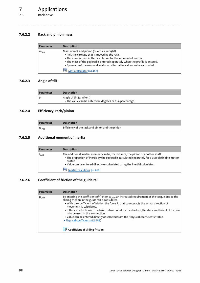
7 Applications7.6 Rack drive
_ _ _ _ _ _ _ _ _ _ _ _ _ _ _ _ _ _ _ _ _ _ _ _ _ _ _ _ _ _ _ _ _ _ _ _ _ _ _ _ _ _ _ _ _ _ _ _ _ _ _ _ _ _ _ _ _ _ _ _ _ _ _ _
7.6.2.2 Rack and pinion mass
7.6.2.3 Angle of tilt
7.6.2.4 Efficiency, rack/pinion
7.6.2.5 Additional moment of inertia
7.6.2.6 Coefficient of friction of the guide rail
Parameter Description
maux Mass of rack and pinion (or vehicle weight)• Incl. the carriage that is moved by the rack.• The mass is used in the calculation for the moment of inertia• The mass of the payload is entered separately when the profile is entered.• By means of the mass calculator an alternative value can be calculated.
Mass calculator ( 467)
Parameter Description
Angle of tilt (gradient)• The value can be entered in degrees or as a percentage.
Parameter Description
Cog Efficiency of the rack and pinion and the pinion
Parameter Description
Jadd The additional inertial moment can be, for instance, the pinion or another shaft.• The proportion of inertia by the payload is calculated separately for a user-definable motion
profile.• Value can be entered directly or calculated using the inertial calculator.
Inertial calculator ( 469)
Parameter Description
μGdn By entering the coefficient of friction Gdn, an increased requirement of the torque due to the sliding friction in the guide rail is considered.
• With the coefficient of friction the force F that counteracts the actual direction of movement is calculated.
• If the static friction is to be taken into account for the start-up, the static coefficient of friction is to be used in this connection.
• Value can be entered directly or selected from the "Physical coefficients" table.Physical coefficients ( 485)
Coefficient of sliding friction
98 Lenze · Drive Solution Designer · Manual · DMS 4.9 EN · 10/2019 · TD23

7 Applications7.6 Rack drive
_ _ _ _ _ _ _ _ _ _ _ _ _ _ _ _ _ _ _ _ _ _ _ _ _ _ _ _ _ _ _ _ _ _ _ _ _ _ _ _ _ _ _ _ _ _ _ _ _ _ _ _ _ _ _ _ _ _ _ _ _ _ _ _
7.6.2.7 Speed
7.6.2.8 Counterforce
7.6.2.9 Mass of the payload
Parameter Description
v Speed (translatory)• Value is entered in the Motion dimensioning step.
Parameter Description
Fvs Force that works against the direction of movement.• Value is entered in the Motion dimensioning step.
The sign of the counterforce determines its effective direction:• If the speed is positive,
• positive values act opposite to the direction of travel• negative values act with the direction of travel.
• If the speed is negative,• positive values act with the direction of travel• negative values act opposite to the direction of travel.
Note!
If the force acts in a supporting manner, the opposite sign is to be entered.
Parameter Description
mL Mass of the payload without vehicle.• Value is entered in the Motion dimensioning step.
Lenze · Drive Solution Designer · Manual · DMS 4.9 EN · 10/2019 · TD23 99

7 Applications7.7 Spindle drive
_ _ _ _ _ _ _ _ _ _ _ _ _ _ _ _ _ _ _ _ _ _ _ _ _ _ _ _ _ _ _ _ _ _ _ _ _ _ _ _ _ _ _ _ _ _ _ _ _ _ _ _ _ _ _ _ _ _ _ _ _ _ _ _
7.7 Spindle drive
The vast majority of positioning systems require linear movements. If a rotating drive is used, therotation of the motor has to be converted into a linear movement. The speeds that can be achieved,and therefore the dynamics of the positioning process and the repeat accuracy, and thus the qualityof the positioning process to a great extent are defined by the mechanics.
Characteristics of a spindle drive
• A motor (if required with a gearbox) actuates a spindle that moves the spindle slide with the load.
• Spindles are used for a high positioning accuracy and low speeds. The positioning path is limited.
• For the accurate adjustment of limit stops and the accurate positioning of the workpiece in production machines, spindles are generally used.
7.7.1 Calculations
For a spindle drive according to the drawing the following applies:
First the leadscrew pitch is converted to a resulting radius.
[7-52] Equation 1: Resulting radius of the spindle
The moment of inertia of the spindle can be determined if its geometry is known.
• The following, for instance, applies to a solid cylinder:
[7-53] Equation 2: Moment of inertia of the spindle
rRes
hSpl
2000 ---------------------=
Jadd
32 10004
--------------------------- dSpl
4lSpl =
100 Lenze · Drive Solution Designer · Manual · DMS 4.9 EN · 10/2019 · TD23

7 Applications7.7 Spindle drive
_ _ _ _ _ _ _ _ _ _ _ _ _ _ _ _ _ _ _ _ _ _ _ _ _ _ _ _ _ _ _ _ _ _ _ _ _ _ _ _ _ _ _ _ _ _ _ _ _ _ _ _ _ _ _ _ _ _ _ _ _ _ _ _
The efficiency of the spindle is calculated according to the following equation.
• The coefficient of friction Spl of the spindle depends on the spindle type. Here, rolling spindles and trapezoidal spindles are distinguished.
[7-54] Equation 3: Leadscrew efficiency
Conversion of translatory variables into rotary variables
[7-55] Equation 4: Angle
[7-56] Equation 5: Angular velocity
[7-57] Equation 6: Angular acceleration
Forces of the linear motion
First the mass which is to be moved linearly has to be calculated. The payload mL can adopt differentvalues during the travel cycle. The mass of carriage maux is considered separately.
[7-58] Equation 7: Total mass
The friction force F acts opposite to the direction of movement and is taken into consideration byv/|v| in the following equation, where F = 0 if v = 0.
[7-59] Equation 8: Friction force
Spl
1 k Spl–
1Spl
k----------+
-------------------------- with k hSpl
dSpl-----------------==
2000 s
hSpl---------- =
2000 v
hSpl---------- =
2000 a
hSpl---------- =
msum mL maux+=
F msum g Gdn cosvv----- =
Lenze · Drive Solution Designer · Manual · DMS 4.9 EN · 10/2019 · TD23 101

7 Applications7.7 Spindle drive
_ _ _ _ _ _ _ _ _ _ _ _ _ _ _ _ _ _ _ _ _ _ _ _ _ _ _ _ _ _ _ _ _ _ _ _ _ _ _ _ _ _ _ _ _ _ _ _ _ _ _ _ _ _ _ _ _ _ _ _ _ _ _ _
Additionally a force Fvs can act, e. g. a force due to weight during a slope of the linear movement.
• Fvs is an external counterforce that can act additionally on the slide or the spindle. The direction of the force is to be observed.
[7-60] Equation 9: Total translatory force
Required torque of the application
The required torque of the application MApp has to be calculated in three steps. First the force thatis transmitted via the spindle has to be ascertained:
[7-61] Equation 10: Force of the slide on the spindle
The friction force depends on the force FApp to be transmitted, so that the resulting force that istransmitted via the spindle is calculated by means of the following equation.
• It is assumed that is the leadscrew efficiency in motor mode. The deterioration of the efficiency for operation in generator mode (backward efficiency) is taken into consideration during this calculation.
[7-62] Equation 11: Force transmitted to the slide, taking the spindle friction into consideration
Consideration of axial forces
In the case of rack and pinions with helical teeth, there are axial forces resulting in a stress for theshaft bearings on the gearbox output end or on the motor.
The DSD does not calculate axial forces. You have to check them separately and take them intoconsideration during the dimensioning process.
Torque
For calculating the required torque of the application, the additional moments of inertia (e. g. thatof the spindle) are to be taken into consideration.
[7-63] Equation 13: Required torque of the application
Tip!
Further equations to complete the calculations required for an application can be found inthe chapter "Basic calculations". ( 67)
Fsum Fvs m+sum
g sin =
FApp Fsum F+ m+sum
a=
FApp, FApp FAppvv----- 1
Spl---------- 1– +=
MApp rRes FApp, Jadd +=
102 Lenze · Drive Solution Designer · Manual · DMS 4.9 EN · 10/2019 · TD23

7 Applications7.7 Spindle drive
_ _ _ _ _ _ _ _ _ _ _ _ _ _ _ _ _ _ _ _ _ _ _ _ _ _ _ _ _ _ _ _ _ _ _ _ _ _ _ _ _ _ _ _ _ _ _ _ _ _ _ _ _ _ _ _ _ _ _ _ _ _ _ _
7.7.1.1 Symbols used
Symbol Description Dimension unit
a Acceleration (translatory) m/s2
dSpl Friction diameter of the spindle mm
F External friction force N
Fvs Counterforce N
Fsum Total translatory force N
FApp Force of slide on the spindle N
FApp, FApp, taking the spindle friction into consideration N
g Gravitational acceleration (g = 9.81 m/s2) m/s2
hSpl Leadscrew pitch mm
Jadd Additional moment of inertia, e. g. of the spindle kgm2
JL Moment of inertia of load kgm2
Jsums Total moment of inertia kgm2
lSpl Spindle length mm
mL Mass of the payload kg
maux Mass of the slide kg
msum Total mass kg
MApp Required torque of the application Nm
Density of the spindle material kg/dm3
rres Resulting radius of the spindle m
s Path (translatory) m
v Speed (translatory) m/s
Angular acceleration rad/s2
Angle of tilt °
Spl Spindle efficiency
Angle rad
Gdn Coefficient of friction of the guide rail
Spl Coefficient of friction of the spindle
Angular velocity rad/s
Lenze · Drive Solution Designer · Manual · DMS 4.9 EN · 10/2019 · TD23 103

7 Applications7.7 Spindle drive
_ _ _ _ _ _ _ _ _ _ _ _ _ _ _ _ _ _ _ _ _ _ _ _ _ _ _ _ _ _ _ _ _ _ _ _ _ _ _ _ _ _ _ _ _ _ _ _ _ _ _ _ _ _ _ _ _ _ _ _ _ _ _ _
7.7.2 Data for the entry
7.7.2.1 Leadscrew pitch
7.7.2.2 Mass of the slide
7.7.2.3 Angle of tilt
7.7.2.4 Spindle efficiency
7.7.2.5 Spindle moment of inertia
Parameter Description
hSpl Leadscrew pitch• Path moved per spindle revolution
Parameter Description
maux Mass of carriage• The spirally formed guide of the leadscrew thread moves the carriage.• The mass of the carriage is used in the calculation of the inertial moment.• By means of the mass calculator an alternative value can be calculated.
Mass calculator ( 467)
Parameter Description
Angle of tilt (gradient)• The value can be entered in degrees or as a percentage.
Parameter Description
Spl Leadscrew efficiency• If the efficiency is known it can be entered directly.• The leadscrew efficiency can also be calculated from the coefficient of friction.
"Leadscrew efficiency" calculator ( 484)
Parameter Description
Jadd Moment of inertia of the spindle (without mass of the payload)• The proportion of inertia by the mass of the payload is calculated separately by the creation
of the motion profile.• Value can be entered directly or calculated using the inertial calculator.
Inertial calculator ( 469)
104 Lenze · Drive Solution Designer · Manual · DMS 4.9 EN · 10/2019 · TD23

7 Applications7.7 Spindle drive
_ _ _ _ _ _ _ _ _ _ _ _ _ _ _ _ _ _ _ _ _ _ _ _ _ _ _ _ _ _ _ _ _ _ _ _ _ _ _ _ _ _ _ _ _ _ _ _ _ _ _ _ _ _ _ _ _ _ _ _ _ _ _ _
7.7.2.6 Coefficient of friction of the guide rail
7.7.2.7 Speed
7.7.2.8 Mass of the payload
7.7.2.9 Counterforce
Parameter Description
μGdn Coefficient of friction of the guide rail• If there are guide rails absorbing the payload mass, a value for the friction is to be entered.• Value can be entered directly or selected from the "Physical coefficients" table.Physical coefficients ( 485)
Coefficient of sliding friction
Parameter Description
v Traversing speed• Value is entered in the Motion dimensioning step.
Parameter Description
mL Mass of payload• Value is entered in the Motion dimensioning step.
Parameter Description
Fvs Force that works against the direction of movement.• Value is entered in the Motion dimensioning step.
The sign of the counterforce determines its effective direction:• If the speed is positive,
• positive values act opposite to the direction of travel• negative values act with the direction of travel.
• If the speed is negative,• positive values act with the direction of travel• negative values act opposite to the direction of travel
Note!
If the force acts in a supporting manner, the opposite sign is to be entered.
Lenze · Drive Solution Designer · Manual · DMS 4.9 EN · 10/2019 · TD23 105

7 Applications7.8 Wheel drive
_ _ _ _ _ _ _ _ _ _ _ _ _ _ _ _ _ _ _ _ _ _ _ _ _ _ _ _ _ _ _ _ _ _ _ _ _ _ _ _ _ _ _ _ _ _ _ _ _ _ _ _ _ _ _ _ _ _ _ _ _ _ _ _
7.8 Wheel drive
Wheel drives are used in non-continuous conveyors. The drives are on the vehicle and therefore onthe non-stationary part. Compared to continuous conveyors, non-continuous conveyors have agreater flexibility, but also higher costs for the individual vehicle. Therefore they are usually used forcases where the transport volume and the use of the conveyor section is lower than for continuousconveyors. t,
There are railway vehicles and non-railway vehicles. For railway vehicles the effort for tracking islower, however, they are not as flexible with regard to the routing . Since many automated internaltransport tasks have a defined travel way, they are frequently found in automated operation. Fornon-automated internal transport the manually operated fork lift still is the most frequently usedmeans of transport in the field of industrial trucks.
Wheel drives in non-continuous conveyors can be found in the following applications:
• In rail vehicles (e. g. transfer carriages)
• In monorail overhead conveyors (MOC)
• In travelling and gantry cranes
• In storage and retrieval units (SRU)
• In automated guided vehicle systems (AGV).
Note!
The calculation only applies to travelling drives which are solely actuated by means of wheels (no rope or rack and pinion).
Applications with toothed belts can be found in connection with the belt models.
106 Lenze · Drive Solution Designer · Manual · DMS 4.9 EN · 10/2019 · TD23

7 Applications7.8 Wheel drive
_ _ _ _ _ _ _ _ _ _ _ _ _ _ _ _ _ _ _ _ _ _ _ _ _ _ _ _ _ _ _ _ _ _ _ _ _ _ _ _ _ _ _ _ _ _ _ _ _ _ _ _ _ _ _ _ _ _ _ _ _ _ _ _
7.8.1 Calculations
For a wheel drive according to the drawing the following applies:
Moment of inertia
The moment of inertia JCar is the part of inertia which does not change during the processing cycle,e. g. mass of the vehicle (mCar), axes, and wheels.
[7-64] Equation 1: Moment of inertia of the vehicle
The part of the payload mass (mL) is added. This mass can adopt different values within theprocessing cycle.
[7-65] Equation 2: Total moment of inertia
Stationary torque
The ascertainment of the stationary torque is based on the determination of the vehicle travellingresistance. It can consist of the proportion of rolling friction, bearing friction, and wheel flange andlateral friction. Additionally tensile and hoisting forces can act.
[7-66] Equation 3: Total mass
[7-67] Equation 4: Stationary torque
[7-68] Equation 5: Friction torque
[7-69] Equation 6: Counter-torque
[7-70] Equation 7: Lifting torque
JCar Jadd
dWhl
2000-------------
2mCar+=
Jsum JCar
dWhl
2000-------------
2mL+=
msum mCar mL+=
Msds M Mvs Mg+ +=
M msum gvv----- f
1000------------- cos
dBrg
2000-------------+ 1
dWhl
2000------------- c+
=
Mvs Fvs
dWhl
2000-------------=
Mg msum g sindWhl
2000------------- =
Lenze · Drive Solution Designer · Manual · DMS 4.9 EN · 10/2019 · TD23 107

7 Applications7.8 Wheel drive
_ _ _ _ _ _ _ _ _ _ _ _ _ _ _ _ _ _ _ _ _ _ _ _ _ _ _ _ _ _ _ _ _ _ _ _ _ _ _ _ _ _ _ _ _ _ _ _ _ _ _ _ _ _ _ _ _ _ _ _ _ _ _ _
Alternatively the travelling resistance F’ can be related to the mass [N/t]:
[7-71] Equation 8: Travelling resistance
[7-72] Equation 9: Friction torque
Application torque
[7-73] Equation 10: Torque of the application
Spinning
In order to prevent the drive wheels from spinning, a maximum permissible acceleration can bedetermined. In the calculation the wheel load, the angle of tilt, the total mass, and the frictioncoefficient and a possible counterforce (Fvs) are taken into consideration.
[7-74] Equation 11: Permissible spinning acceleration
Driving against a limit stop
The maximum torque during driving against a limit stop depends on the friction force and thediameter of the driving wheels. After the friction force has been overcome, the torque is reduced byspinning wheels.
[7-75] Equation 12: Torque at the gearbox output during driving against a limit stop
Tip!
Further equations to complete the calculations required for an application can be found inthe chapter "Basic calculations". ( 67)
F’ g 2 f cos dWhl
---------------------------dBrg Brg
dWhl-------------------------- c+ +
1000 =
Mμ FμdWhl
2000-------------
F’ msum
1000-----------------------
dWhl
2000------------- v
v----- = =
MApp Msds Jsum +=
aper g 0
mWhl
msum-------------- cos sin–
Fvs
msum--------------+=
M0 msum g 0
dWhl
2000------------- cos =
108 Lenze · Drive Solution Designer · Manual · DMS 4.9 EN · 10/2019 · TD23

7 Applications7.8 Wheel drive
_ _ _ _ _ _ _ _ _ _ _ _ _ _ _ _ _ _ _ _ _ _ _ _ _ _ _ _ _ _ _ _ _ _ _ _ _ _ _ _ _ _ _ _ _ _ _ _ _ _ _ _ _ _ _ _ _ _ _ _ _ _ _ _
7.8.1.1 Symbols used
Symbol Description Dimension unit
aper Slip acceleration m/s2
C Wheel flange and lateral friction
dWhl Wheel diameter mm
dBrg Bearing diameter mm
f Lever arm of the rolling friction mm
F’ Specific travelling resistance N/t
Fμ Force of travelling resistance N
Fvs Counterforce N
g Gravitational acceleration (g = 9.81 m/s2) m/s2
Jadd Additional moment of inertia kgm2
JCar Moment of inertia of vehicle kgm2
Jsum Total moment of inertia kgm2
mL Mass of the payload kg
mCar Mass of the vehicle kg
msum Total mass kg
mWhl Wheel load of the driven wheel kg
Mvs Counter-torque Nm
Mg Lifting torque Nm
MApp Required torque of the application Nm
Msds Stationary torque Nm
M Friction torque Nm
M Max. torque during driving against a limit stop Nm
Angle of tilt °
Brg Bearing friction
0 Static friction of wheel/road surface
Lenze · Drive Solution Designer · Manual · DMS 4.9 EN · 10/2019 · TD23 109

7 Applications7.8 Wheel drive
_ _ _ _ _ _ _ _ _ _ _ _ _ _ _ _ _ _ _ _ _ _ _ _ _ _ _ _ _ _ _ _ _ _ _ _ _ _ _ _ _ _ _ _ _ _ _ _ _ _ _ _ _ _ _ _ _ _ _ _ _ _ _ _
7.8.2 Data for the entry
7.8.2.1 Wheel diameter
7.8.2.2 Mass of the vehicle
7.8.2.3 Additional moment of inertia
7.8.2.4 Angle of tilt
Parameter Description
dWhl Diameter of the wheel that is used to drive the vehicle.
Parameter Description
mCar Mass of the vehicle without payload• The value can be entered directly or calculated using the mass calculator.• When the motion profile is entered, the payload is assigned to the individual subprofiles.
Mass calculator ( 467)
Parameter Description
Jadd Additional moment of inertia due to wheels, axes, etc.• Has an impact on the dynamic torque!• Value can be entered directly or calculated using the inertial calculator.
Inertial calculator ( 469)
Parameter Description
Angle of tilt (gradient)• The value can be entered in degrees or as a percentage.• The max. angle of tilt as a first approximation is: arctan(μ0)
(static friction between the wheel and road surface).• The angle of tilt of the travel path must be considered when determining the travelling
resistance. For a tilted travel path ( 0), the specific travelling resistance must be recalculated by means of the "Travelling resistance" calculator and the values for the wheel diameter and the angle of tilt.
"Travelling resistance" calculator ( 481)
110 Lenze · Drive Solution Designer · Manual · DMS 4.9 EN · 10/2019 · TD23

7 Applications7.8 Wheel drive
_ _ _ _ _ _ _ _ _ _ _ _ _ _ _ _ _ _ _ _ _ _ _ _ _ _ _ _ _ _ _ _ _ _ _ _ _ _ _ _ _ _ _ _ _ _ _ _ _ _ _ _ _ _ _ _ _ _ _ _ _ _ _ _
7.8.2.5 Specific travelling resistance
VULKOLLAN wheels
VULKOLLAN wheels are particularly suitable for conveyors and drives for loads up to 10 t or evenmore.
• For the determination of the travelling resistance the following table can be included:
• Usually the consideration of the rolling friction is sufficient with regard to determining the travelling resistance. Only for applications featuring frequent start-stop processes, the travelling resistance increases due to the starting resistance.
7.8.2.6 Speed
7.8.2.7 Mass of the payload
Parameter Description
F’ Specific travelling resistance• If the specific travelling resistance is calculated via the "travelling resistance" calculator, the
values for wheel diameter and angle of tilt must be entered in the calculator for this purpose.
"Travelling resistance" calculator ( 481)
Note!
VULKOLLAN is a registered trademark of BAYER AG.
Travelling resistance in % Travelling resistance in N/t
Rolling resistance at 20 °C in % of load
0.8 to 0.9 80 to 90
Start-up resistance at 20 °C in % of load
1.1 to 1.4 110 to 140
Parameter Description
v Velocity of the vehicle• Value is entered in the Motion dimensioning step.
Parameter Description
mL Mass of the payload without vehicle.• Value is entered in the Motion dimensioning step.
Lenze · Drive Solution Designer · Manual · DMS 4.9 EN · 10/2019 · TD23 111

7 Applications7.8 Wheel drive
_ _ _ _ _ _ _ _ _ _ _ _ _ _ _ _ _ _ _ _ _ _ _ _ _ _ _ _ _ _ _ _ _ _ _ _ _ _ _ _ _ _ _ _ _ _ _ _ _ _ _ _ _ _ _ _ _ _ _ _ _ _ _ _
7.8.2.8 Counterforce
Parameter Description
Fvs Force that acts in the opposite direction to the movement, caused, for instance, by a trailer or wind resistance.
• Value is entered in the Motion dimensioning step.The sign of the counterforce determines its effective direction:
• If the speed is positive,• positive values act opposite to the direction of travel,• negative values act with the direction of travel.
• If the speed is negative,• positive values act with the direction of travel,• negative values act opposite to the direction of travel.
Note!
If the force is to have a supporting function, the opposed sign is to be entered.
112 Lenze · Drive Solution Designer · Manual · DMS 4.9 EN · 10/2019 · TD23

7 Applications7.9 Hoist drive without counterweight
_ _ _ _ _ _ _ _ _ _ _ _ _ _ _ _ _ _ _ _ _ _ _ _ _ _ _ _ _ _ _ _ _ _ _ _ _ _ _ _ _ _ _ _ _ _ _ _ _ _ _ _ _ _ _ _ _ _ _ _ _ _ _ _
7.9 Hoist drive without counterweight
In the case of winches, power is transmitted from the drive on the load via a cable drum and a rope.The load can be arranged with or without a vertical guide (rolls, slide rails). The rope can be deflectedonce or several times or have reevings (pulley block principle). By means of ropes or belts only onedirection of force can be transmitted. Therefore it is only used for applications with a lowacceleration clearly below the acceleration due to gravity of 1 g (1 g = 9.81 m/s²). Typical winchapplications are load cranes of all types, scenery winches in theatres, storage and retrieval units, andmanually operated hoists. A winch installation controlled by the winch speed is connected to thewinch mechanically or electrically via an individual installation drive and carries out the correctinstallation of the cable in one or several layers. One-layer systems partly have grooves in the cabledrum, into which the cable is installed.
• Cranes that are designed as overhead cranes, gantry cranes and construction cranes or as simple hoists lift loads by means of cable winches and operate with different types of reeving. The drive units, just like the wheel drives, are often mounted to constructional elements that travel along.
• In order to move sceneries in theatres vertically, often several cables are required next to each other for each scenery, which act on the sceneries via cross members. The cables of the stage and scenery lifters are wound synchronously on mechanically coupled winches that are axially arranged next to each other. The winches are actuated by a central hoist drive. Tangential pressure rollers provide for a safe cable guide in the grooves of the cable drum. The cables can have lengths of up to 50 m.
• When the application is calculated in the DSD, changes of the cable drum radius during winding and additional losses can be taken into consideration.
Note!
This application model of the DSD is only suitable for applications in which the cable drum diameter does not change at all or only changes slightly. The impact of the changing cable drum diameter is only taken into consideration in the torque diagrams, but not in the interaction of speed and velocity diagrams.
Lenze · Drive Solution Designer · Manual · DMS 4.9 EN · 10/2019 · TD23 113

7 Applications7.9 Hoist drive without counterweight
_ _ _ _ _ _ _ _ _ _ _ _ _ _ _ _ _ _ _ _ _ _ _ _ _ _ _ _ _ _ _ _ _ _ _ _ _ _ _ _ _ _ _ _ _ _ _ _ _ _ _ _ _ _ _ _ _ _ _ _ _ _ _ _
7.9.1 Calculations
For a hoist without counterweight according to the drawing the following applies:
When a cable drum is wound up and unwound, the effective radius changes, which is required forthe calculation of the torque acting on the cable drum. Since, depending on the operating mode(constant speed or constant lifting speed), the speed or velocity changes, the dimensioning processis carried out according to the base process power, and the most unfavourable case is assumed:
[7-76] Equation 1: Base process power
[7-77] Operating modes
1. Operating mode with a constant speed• In the case of this operating mode which is the most frequently used, the input speed –
irrespective of the respective layer – is kept constant on the winding drum.• During a layer change, the lifting speed increases abruptly with every additional layer.• The torque required changes abruptly during a layer change (layer 1, 2, … n).
2. Operating mode with a constant lifting speed• In this operating mode, the input speed is altered depending on the current layer on the cable
drum, so that always a constant lifting speed (v = dCor * n * /60) is reached. For this, the inverter or an external control has to update the speed depending on the layer.
• The required torque also changes abruptly during a layer change. The difference with regard to the operating mode with a constant speed is that the highest speed and the highest torque do not occur simultaneously.
The DSD carries out the dimensioning process identically for both operating modes according to thebase process power (product from max. torque and max. speed). During all calculation routines andgraphic representations only the maximum values are ascertained and displayed.
Pcto MApp nmax2 60----------- =
Operating mode with a constant speedOperating mode with a constant lifting speed
114 Lenze · Drive Solution Designer · Manual · DMS 4.9 EN · 10/2019 · TD23

7 Applications7.9 Hoist drive without counterweight
_ _ _ _ _ _ _ _ _ _ _ _ _ _ _ _ _ _ _ _ _ _ _ _ _ _ _ _ _ _ _ _ _ _ _ _ _ _ _ _ _ _ _ _ _ _ _ _ _ _ _ _ _ _ _ _ _ _ _ _ _ _ _ _
Minimum/maximum diameter
If a cable drum is used a minimum and maximum diameter for the dimensioning has to bedetermined.
• The following illustration shows the parameters required for the calculation for a cable drum:
[7-78] Example: Cable drum
For the determination of the required speed nmax at the required lifting speed v, the minimumeffective reel diameter dmin has to be specified:
[7-79] Equation 2: Minimum diameter
For the determination of the moments of inertia and the stationary torque the maximum effectivediameter dmax is required. For this the number of cable layers on the drum at maximum liftingheight has to be determined.
If we assume that the reel diameter increases by the cable thickness (dRop) with every winding layer,the achievable height hN per winding layer NCor can be calculated by means of the equation below:
[7-80] Equation 3: Achievable height for the winding layer NCor
The winding layer NCor(h) can be calculated depending on hhoi using the following equa-tion:
[7-81] Equation 4: Winding layer NCor(h)
The winding layer NCor which only exists as integer thus results from the rounded up value ofNCor(h):
[7-82] Equation 5: Winding layer NCor
The maximum effective diameter dmax of the cable drum is calculated according to the followingequation:
dMin dCor dRop+=
hN
bCor
dRop----------- dCor dRop+ 2 NCor 1–
NL 1=
NCor
=
NCor h dCor
2 dRop------------------- 2 hhoi 1000 NL
bCor---------------------------------------+
dCor
2 dRop-------------------–=
NCor NCor h =
Lenze · Drive Solution Designer · Manual · DMS 4.9 EN · 10/2019 · TD23 115

7 Applications7.9 Hoist drive without counterweight
_ _ _ _ _ _ _ _ _ _ _ _ _ _ _ _ _ _ _ _ _ _ _ _ _ _ _ _ _ _ _ _ _ _ _ _ _ _ _ _ _ _ _ _ _ _ _ _ _ _ _ _ _ _ _ _ _ _ _ _ _ _ _ _
[7-83] Equation 6: Maximum diameter
Moment of inertia
The moment of inertia J does not change during the lifting cycle. It is, for instance, determined bythe mass of the hoisting cage (mCbn) and the additional moment of inertia (Jadd).
[7-84] Equation 7: Fixed moment of inertia
In the case of applications with many cable rolls and a long cable, the cable rolls and the cable masssubstantially contribute to the peak torque value. For the determination of the cable mass thefollowing equation can be used:
[7-85] Equation 8: Cable mass
For the total moment of inertia (Jsum) of the application the mass of the payload is taken intoconsideration. During the lifting cycle the mass of the payload can be different.
[7-86] Equation 9: Total moment of inertia
Stationary torque
The stationary torque is calculated from the masses assessed with the reeving NL.
[7-87] Equation 10: Stationary torque
Tip!
The cable mass usually can be disregarded, since the force due to weight of the cablecancels itself out in the case of a pulley block.
In few cases (e. g. in the case of long lifting paths), however, the cable force due to weighthas to be taken into consideration. Since it is not the total cable mass that acts effectively,an active cable mass for the stationary torque (macv,Rop) has to be specified.
dmax dCor dRop 2 NCor 1– +=
J Jadd
dmax
2000-------------
2 mCbn
NL2
------------- mRop+ +=
mRop Rop lRop 10 dRop
2000-------------
2 = =
Jsum Jdmax
2000-------------
2 mL
NL2
---------+=
Msds
g dmax
2000--------------------
mL
NL-------
mCbn
NL------------- mRop,1+ +
=
116 Lenze · Drive Solution Designer · Manual · DMS 4.9 EN · 10/2019 · TD23

7 Applications7.9 Hoist drive without counterweight
_ _ _ _ _ _ _ _ _ _ _ _ _ _ _ _ _ _ _ _ _ _ _ _ _ _ _ _ _ _ _ _ _ _ _ _ _ _ _ _ _ _ _ _ _ _ _ _ _ _ _ _ _ _ _ _ _ _ _ _ _ _ _ _
Ascertainment of the active cable mass
The active cable mass is ascertained by means of the mass calculator (field: cylinder) and iscalculated with the following equation:
[7-88] Equation 11: Active cable mass for the stationary torque
Ascertainment of the height difference
For the stationary torque the maximum height difference h is required.
[7-89] Determination of h
Torque loss
In order to take the losses for the hoist into consideration, the friction torque is calculated from theindividual efficiencies. In the case of a dimensioning process with a user-definable motion profile,the efficiency is assumed for a run with the maximum steady-state torque.
• The sign is considered with the fraction n/|n|.
• The following equation calculates the torque loss in generator and motor mode:
[7-90] Equation 12: Torque loss
Application torque
[7-91] Equation 14: Torque of the application
macv Rop Rop h 10 dRop
200-----------
2 =
• The height h typically is the height difference from the winding drum to the cable end of the payload at the lowest position of the payload.
• The yellow highlighted cable sections (+) are decisive for the steady-state torque.
• The other cable sections (+) cancel each other out.
�h
�
�
�
�
Mth1
Gdn Pll Cor ----------------------------------------- 1– max Msds
nn------ =
MApp Msds Jsum Mth++=
Lenze · Drive Solution Designer · Manual · DMS 4.9 EN · 10/2019 · TD23 117

7 Applications7.9 Hoist drive without counterweight
_ _ _ _ _ _ _ _ _ _ _ _ _ _ _ _ _ _ _ _ _ _ _ _ _ _ _ _ _ _ _ _ _ _ _ _ _ _ _ _ _ _ _ _ _ _ _ _ _ _ _ _ _ _ _ _ _ _ _ _ _ _ _ _
Required speed
For the determination of the required speed (n) of the cable drum apart from the previouslymentioned parameters the required lifting speed (v) has to be specified:
[7-92] Equation 15: Speed of the cable drum
Tip!
Further equations to complete the calculations required for an application can be found inthe chapter "Basic calculations". ( 67)
7.9.1.1 Symbols used
n60
2 ----------- v
60------
NL 2000
dMin------------------------ =
Symbol Description Dimension unit
bCor Width of cable drum mm
dCor Diameter of cable drum mm
dmax Maximum effective diameter of cable drum mm
dmin Minimum effective diameter of cable drum mm
dRop Cable diameter mm
g Gravitational acceleration (g = 9.81 m/s2) m/s2
hhoi Lifting height for the determination of the winding layers m
h Height difference for the determination of the stationary torque m
hN Achievable height for winding layer N m
Jadd Additional moment of inertia (e. g. by the cable drum) kgm2
J Stationary moment of inertia without payload mass kgm2
Jsum Total moment of inertia with payload mass kgm2
NCor Number of winding layers on the cable drum
NL Reeving of the pulley block with regard to the payload
lRop Cable length m
mL Mass of the payload kg
mCbn Mass of the hoisting cage for the payload kg
mRop Cable mass kg
macv,Rop Active cable mass (for stationary torque) kg
msum Total mass kg
MApp Required torque of the application Nm
Msds Stationary torque Nm
Mth Torque loss Nm
n Speed of the cable drum rpm
v Lifting speed of the payload m/min
Angular acceleration rad/s2
Gdn Shaft efficiency
Pll Efficiency of the cable rolls
Cor Efficiency of the cable drum
Rop Specific cable weight kg/dm3
118 Lenze · Drive Solution Designer · Manual · DMS 4.9 EN · 10/2019 · TD23

7 Applications7.9 Hoist drive without counterweight
_ _ _ _ _ _ _ _ _ _ _ _ _ _ _ _ _ _ _ _ _ _ _ _ _ _ _ _ _ _ _ _ _ _ _ _ _ _ _ _ _ _ _ _ _ _ _ _ _ _ _ _ _ _ _ _ _ _ _ _ _ _ _ _
7.9.2 Data for the entry
7.9.2.1 Diameter of cable drum
7.9.2.2 Reeving, load
Cable guided hoists have both simple- and multi-cable guides via guide pulleys, so-called reevings(pulley block principle). For multi-cable guides, the circumferential speed of the cable drum is aninteger multiple of the lifting speed. Here, the required torque on the cable drum decreases by thereeving factor NL and the speed increases by this factor.
The reeving has no impact on the drive power (except for highly dynamic movements).
[7-93] Reeving
7.9.2.3 Mass of hoisting cage
7.9.2.4 Efficiency of the cable drum
Parameter Description
dCor Diameter of the cable drum without cable
Parameter Description
NL The reeving of the cable to the payload.• The reeving is the ratio of cable velocity of the cable drum to the lifting speed of the payload.
Reeving for a cable guide via guide pulleys. The reeving factor NL in this case is 4 ().
Parameter Description
mCbn Mass of the hoisting cage for the payload• Value can be entered directly or calculated using the mass calculator.
Mass calculator ( 467)
Parameter Description
Cor Efficiency limited by friction between cable drum and cable
Lenze · Drive Solution Designer · Manual · DMS 4.9 EN · 10/2019 · TD23 119

7 Applications7.9 Hoist drive without counterweight
_ _ _ _ _ _ _ _ _ _ _ _ _ _ _ _ _ _ _ _ _ _ _ _ _ _ _ _ _ _ _ _ _ _ _ _ _ _ _ _ _ _ _ _ _ _ _ _ _ _ _ _ _ _ _ _ _ _ _ _ _ _ _ _
7.9.2.5 Additional moment of inertia
7.9.2.6 Cable diameter
7.9.2.7 Width of cable drum
7.9.2.8 Max. lifting height
7.9.2.9 Cable mass
Parameter Description
Jadd Moment of inertia of the cable drum, the deflection and guiding rollers, etc.• The moment of inertia of the hoisting cage does not have to be taken into consideration here
since it is already included.• The moment of inertia has an effect on the dynamic torque!• Value can be entered directly or calculated using the inertial calculator.
Inertial calculator ( 469)
Parameter Description
dRop Outside diameter of cable
Parameter Description
bCor Width of the cable drum• Is used to determine the number of layers of the cable on the drum, and thus the increase in
the effective drum diameter.
Parameter Description
hhoi Maximum achievable lifting height• Is used to determine the number of layers of the cable on the drum, and thus the increase in
the effective drum diameter.• If the winding layers do not have to be taken into consideration, hhoi is set to 0.
Parameter Description
mRop Mass of cable• Value can be entered directly or calculated using the auxiliary calculator.
"Mass of rope/cable (hoist drive)" calculator ( 476)
120 Lenze · Drive Solution Designer · Manual · DMS 4.9 EN · 10/2019 · TD23

7 Applications7.9 Hoist drive without counterweight
_ _ _ _ _ _ _ _ _ _ _ _ _ _ _ _ _ _ _ _ _ _ _ _ _ _ _ _ _ _ _ _ _ _ _ _ _ _ _ _ _ _ _ _ _ _ _ _ _ _ _ _ _ _ _ _ _ _ _ _ _ _ _ _
Determination of the mass
The cable mass is either calculated by means of the mass calculator (field: cylinder) or with thefollowing equation:
7.9.2.10 Active cable mass
7.9.2.11 Shaft efficiency
7.9.2.12 Efficiency of the rolls
7.9.2.13 Lifting speed
7.9.2.14 Mass of the payload
mRop Rop lRop 10 dRop
200-----------
2 =
Parameter Description
macv,Rop Active mass of cable• Is the mass that is relevant for the stationary moment, i.e. the mass that acts as a weight on
the cable drum.• Value can be entered directly or calculated using the auxiliary calculator.
"Mass of rope/cable (hoist drive)" calculator ( 476)
Parameter Description
Gdn Efficiency resulting from the friction of the hoisting cage at the hoisting shaft
Parameter Description
Pll Efficiency resulting from friction between the cable rolls and the cable
Parameter Description
v Lifting speed of the payload• Value is entered in the Motion dimensioning step.
Parameter Description
mL Mass of payload• Value is entered in the Motion dimensioning step.
Lenze · Drive Solution Designer · Manual · DMS 4.9 EN · 10/2019 · TD23 121

7 Applications7.10 Hoist drive with counterweight
_ _ _ _ _ _ _ _ _ _ _ _ _ _ _ _ _ _ _ _ _ _ _ _ _ _ _ _ _ _ _ _ _ _ _ _ _ _ _ _ _ _ _ _ _ _ _ _ _ _ _ _ _ _ _ _ _ _ _ _ _ _ _ _
7.10 Hoist drive with counterweight
In comparison to winches, hoists with driving pulleys and counterweights have the advantage thatthe cable length practically is only limited by the dead weight of the cables. Hoists with drivingpulleys are basically equipped with counterweights that are conducted to the sides of the shaft,parallel to the cabin.
Normally the counterweight is dimensioned for half the payload. This means that the hoist is inequilibrium when half the payload is loaded. Apart from the two directions of rotation, according tothe payload also two torque directions (in motor mode, in generator mode) can occur.
The cables directly connect the cabin to the counterweight, or by means of mounting suspensionsand run through V-shaped grooves over the driving pulleys with a minimum angle of wrap. Thedriving pulleys that are wrapped by the cables transmit the drive torque to the cables, and thus tothe system consisting of the hoisting cage and the counterweight, by frictional locking.
For safety reasons always several parallel cables (6 to 8 cables) with a very high safety factor (factor12) are used, so that the total load can actually be held by an individual cable. A redundant safetyconcept provides for an extremely high degree of safety, also in the event of a power failure orconductor failure.
Danger!
The DSD must not be used for designing lifts!• The DSD can only calculate hoist drives with counterweight for freight elevators.• The safety-relevant calculations required for lifts are not carried out by the DSD.• Only design hoist drives for lifts in accordance with the applicable national and
regional regulations.
122 Lenze · Drive Solution Designer · Manual · DMS 4.9 EN · 10/2019 · TD23

7 Applications7.10 Hoist drive with counterweight
_ _ _ _ _ _ _ _ _ _ _ _ _ _ _ _ _ _ _ _ _ _ _ _ _ _ _ _ _ _ _ _ _ _ _ _ _ _ _ _ _ _ _ _ _ _ _ _ _ _ _ _ _ _ _ _ _ _ _ _ _ _ _ _
7.10.1 Calculations
For a hoist with counterweight according to the drawing the following applies:
Effective diameter
The following equations require the effective diameter of the traction sheave, resulting from thereel diameter of the traction sheave plus the diameter of the wire:
[7-94] Equation 1: Effective diameter of the driving pulley
Moment of inertia
The moment of inertia J does not change during the lifting cycle. Basically it is determined by themass of the hoisting cage mCag, the mass of the counterweight, and the additional moment ofinertia Jadd.
[7-95] Equation 2: Fixed moment of inertia
Typical masses of counterweight mCtw can be determined from the mass of the hoisting cage mCbn,half of the payload mL and the reeving ratio NCtw/NL:
[7-96] Equation 3: Mass of counterweight
In the case of applications with many guide pulleys and a long cable, the rolls and the cable masssubstantially contribute to the peak torque value. For the determination of the cable mass mRop thefollowing equation can be used:
• If a cable pull with a shear was used, the effective cable mass would be reduced. The following equation does not take a shear into consideration, so that in this case there is a safety reserve.
[7-97] Equation 4: Mass of the entire cable
For the total moment of inertia Jsumof the application additionally the mass of the payload is takeninto consideration. During the lifting cycle the mass of the payload can be different.
[7-98] Equation 5: Total moment of inertia
d dCor dRop+=
J Jaddd
2000------------- 2 mCtw
NCtw2
--------------mCbn
NL2
------------- mRop+ + +=
mCtw
NCtw
NL------------ mCbn
mL
2-------+
=
mRop Rop lRop 10 dRop
200-----------
2 =
Jsum Jd
2000------------- 2 mL
NL2
---------+=
Lenze · Drive Solution Designer · Manual · DMS 4.9 EN · 10/2019 · TD23 123

7 Applications7.10 Hoist drive with counterweight
_ _ _ _ _ _ _ _ _ _ _ _ _ _ _ _ _ _ _ _ _ _ _ _ _ _ _ _ _ _ _ _ _ _ _ _ _ _ _ _ _ _ _ _ _ _ _ _ _ _ _ _ _ _ _ _ _ _ _ _ _ _ _ _
Stationary torque
The stationary torque is calculated from the difference of the masses assessed with the reeving.
[7-99] Equation 6: Stationary torque
Tip!
The mass of the cables usually can be disregarded, since the force due to weight of thecables cancels itself out in the case of a pulley block.
For some applications the cable mass in the most unfavourable position of the hoist is quiteimportant (e. g. in the case of great lifting heights), so that it can be considered as the activecable mass macv,Rop.
For the drive the stationary torque, also on the pulley block, is only the mass of a simplecable, since the masses of the other cables cancel themselves out by the fixed cable rolls.The cable mass for the counterweight can be deducted.
Ascertainment of the active cable mass
The active cable mass is ascertained by means of the mass calculator (field: cylinder) and iscalculated with the following equation:
[7-100] Equation 7: Active cable mass for the stationary torque
Msdsd
2000------------- Fadd g
mL
NL-------
mCbn
NL-------------
mCtw
NCtw--------------– macv,Rop+ + +
=
macv,Rop Rop h 10 dRop
200-----------
2 =
124 Lenze · Drive Solution Designer · Manual · DMS 4.9 EN · 10/2019 · TD23

7 Applications7.10 Hoist drive with counterweight
_ _ _ _ _ _ _ _ _ _ _ _ _ _ _ _ _ _ _ _ _ _ _ _ _ _ _ _ _ _ _ _ _ _ _ _ _ _ _ _ _ _ _ _ _ _ _ _ _ _ _ _ _ _ _ _ _ _ _ _ _ _ _ _
Ascertainment of the height difference
For the stationary torque the maximum height difference h is required.
[7-101] Determination of h
Torque loss
In order to take the losses for the hoist into consideration, the friction torque is calculated from theindividual efficiencies. In the case of a dimensioning process with a user-definable motion profile,the efficiency is assumed for a run with the maximum steady-state torque.
• The sign is considered with the fraction n/|n|.
• The friction of the cable rolls is considered as efficiency Pll in a simplified manner. The efficiency depends on the number of cable rolls, the reeving, and the efficiency of the individual rolls.
• The following equation calculates the torque loss in generator and motor mode:
[7-102] Equation 8: Torque loss
• The height h usually is the height difference from the cable end of the counterweight to the cable end of the payload at the lowest position of the payload or the counterweight.
• The yellow highlighted cable sections (+) are decisive for the steady-state torque.
• The cable sections (+, +) cancel themselves out or are borne by the mounting parts .
Δh
�
�
�
� �
�
�
Mth1
Gdn Pll ---------------------------------- 1– max Msds
nn------ =
Lenze · Drive Solution Designer · Manual · DMS 4.9 EN · 10/2019 · TD23 125

7 Applications7.10 Hoist drive with counterweight
_ _ _ _ _ _ _ _ _ _ _ _ _ _ _ _ _ _ _ _ _ _ _ _ _ _ _ _ _ _ _ _ _ _ _ _ _ _ _ _ _ _ _ _ _ _ _ _ _ _ _ _ _ _ _ _ _ _ _ _ _ _ _ _
Application torque
[7-103] Equation 9: Torque of the application
Required speed
For the determination of the required speed nCor of the driving pulley, apart from the previouslymentioned parameters the required lifting speed v has to be specified.
[7-104] Equation 10: Speed of the driving pulley
The speed of the counterweight vCtw is calculated as follows:
[7-105] Equation 11: Speed of the counterweight
Tip!
Further equations to complete the calculations required for an application can be found inthe chapter "Basic calculations". ( 67)
MApp Msds Jsum Mth++=
n60
2 ----------- v
60------
NL 2000
dCor------------------------ =
vCtw
NL
NCtw------------ v=
126 Lenze · Drive Solution Designer · Manual · DMS 4.9 EN · 10/2019 · TD23

7 Applications7.10 Hoist drive with counterweight
_ _ _ _ _ _ _ _ _ _ _ _ _ _ _ _ _ _ _ _ _ _ _ _ _ _ _ _ _ _ _ _ _ _ _ _ _ _ _ _ _ _ _ _ _ _ _ _ _ _ _ _ _ _ _ _ _ _ _ _ _ _ _ _
7.10.1.1 Symbols used
Symbol Description Dimension unit
d Effective diameter of the traction sheave mm
dCor Reel diameter of the traction sheave mm
dRop Cable diameter mm
Fadd Additional force N
g Gravitational acceleration (g = 9.81 m/s2) m/s2
h Height difference for the determination of the stationary torque m
Jadd Additional moment of inertia kgm2
J Stationary moment of inertia without payload mass kgm2
Jsum Total moment of inertia with payload mass kgm2
NL Reeving of the pulley block with regard to the payload
NCtw Reeving of the pulley block with regard to the counterweight
lRop Cable length m
mL Mass of the payload kg
mCtw Mass of counterweight kg
mCbn Mass of the hoisting cage for the payload kg
mRop Cable mass kg
macv,Rop Active cable mass for stationary torque kg
MApp Required torque of the application Nm
Msds Stationary torque Nm
Mth Torque loss Nm
n Speed of the driving pulley rpm
v Speed of the payload/hoisting cage m/min
vCtw Speed of the counterweight m/min
Angular acceleration of the driving pulley rad/s2
Gdn Shaft efficiency
Pll Efficiency of the cable rolls
Efficiency of the driving pulley
Rop Specific cable weight kg/dm3
Lenze · Drive Solution Designer · Manual · DMS 4.9 EN · 10/2019 · TD23 127

7 Applications7.10 Hoist drive with counterweight
_ _ _ _ _ _ _ _ _ _ _ _ _ _ _ _ _ _ _ _ _ _ _ _ _ _ _ _ _ _ _ _ _ _ _ _ _ _ _ _ _ _ _ _ _ _ _ _ _ _ _ _ _ _ _ _ _ _ _ _ _ _ _ _
7.10.2 Mass in motion
Only the mass on the load side is referred to as "mass in motion". The mass of counterweight mCtwis not taken into consideration.
• The mass in motion is the sum of the mCbn hoisting cage mass and the mL payload mass.
[7-106] Application diagram: Mass in motion
Description
mL Mass of the payload
msum Mass in motion
128 Lenze · Drive Solution Designer · Manual · DMS 4.9 EN · 10/2019 · TD23

7 Applications7.10 Hoist drive with counterweight
_ _ _ _ _ _ _ _ _ _ _ _ _ _ _ _ _ _ _ _ _ _ _ _ _ _ _ _ _ _ _ _ _ _ _ _ _ _ _ _ _ _ _ _ _ _ _ _ _ _ _ _ _ _ _ _ _ _ _ _ _ _ _ _
7.10.3 Data for the entry
7.10.3.1 Diameter of traction sheave
7.10.3.2 Reeving, load
For cable-guided hoists both single- and multi-cable guides via guide pulleys, so-called reevings(pulley block principle) are used. In the case of multi-cable guides the circumferential speed of thedriving pulley is an integer multiple of the lifting speed. The required torque at the driving pulley isdecreased by the reeving factor kL, and the speed increases by this factor.-
The reeving has no impact on the drive power (except for highly dynamic movements).
[7-107] Reeving of the load
Parameter Description
dCor Diameter of traction sheave
Parameter Description
NL The reeving of the cable to the payload.• The reeving is the ratio of the cable velocity of the winding drum to the lifting speed of the
payload.
Reeving for a cable guide via guide pulleys. The reeving factor NL in this case is 4 ().
Lenze · Drive Solution Designer · Manual · DMS 4.9 EN · 10/2019 · TD23 129

7 Applications7.10 Hoist drive with counterweight
_ _ _ _ _ _ _ _ _ _ _ _ _ _ _ _ _ _ _ _ _ _ _ _ _ _ _ _ _ _ _ _ _ _ _ _ _ _ _ _ _ _ _ _ _ _ _ _ _ _ _ _ _ _ _ _ _ _ _ _ _ _ _ _
7.10.3.3 Reeving, counterweight
For cable-guided hoists, also with counterweight, both single- and multi-cable guides via guidepulleys, so-called reevings (pulley block principle) are used.
[7-108] Reeving of counterweight
7.10.3.4 Mass of counterweight
7.10.3.5 Mass of hoisting cage
Parameter Description
NCtw The reeving of the cable to the counterweight.• The reeving is the ratio of the driving pulley cable velocity to the lifting speed of the
counterweight.
Reeving for a cable guide via guide pulleys. The reeving factor NCtw in this case is 3 ().
Parameter Description
mCtw Mass of counterweight• Value can be entered directly or calculated using the auxiliary calculator.
"Mass of counterweight (hoist drive)" calculator ( 475)
Parameter Description
mCbn Mass of the hoisting cage or conveying tools for the payload• Value can be entered directly or calculated using the mass calculator.
Mass calculator ( 467)
130 Lenze · Drive Solution Designer · Manual · DMS 4.9 EN · 10/2019 · TD23

7 Applications7.10 Hoist drive with counterweight
_ _ _ _ _ _ _ _ _ _ _ _ _ _ _ _ _ _ _ _ _ _ _ _ _ _ _ _ _ _ _ _ _ _ _ _ _ _ _ _ _ _ _ _ _ _ _ _ _ _ _ _ _ _ _ _ _ _ _ _ _ _ _ _
7.10.3.6 Additional moment of inertia
7.10.3.7 Cable diameter
7.10.3.8 Cable mass
7.10.3.9 Active cable mass
7.10.3.10 Shaft efficiency
7.10.3.11 Efficiency of the rolls
7.10.3.12 Efficiency of the driving pulley
Parameter Description
Jadd Moment of inertia of the driving pulley, the guide pulleys and guide rollers, etc.• The moment of inertia of the hoisting cage does not have to be taken into consideration here
since it is already included.• The moment of inertia has an effect on the dynamic torque!• Value can be entered directly or calculated using the inertial calculator.
Inertial calculator ( 469)
Parameter Description
dRop Outside diameter of cable
Parameter Description
mRop Mass of cable• Value can be entered directly or calculated using the auxiliary calculator.
"Mass of rope/cable (hoist drive)" calculator ( 476)
Parameter Description
macv,Rop Active mass of cable• Is the mass that is relevant for the stationary moment, i.e. the mass that acts as a weight on
the cable drum.• Value can be entered directly or calculated using the auxiliary calculator.
"Mass of rope/cable (hoist drive)" calculator ( 476)
Parameter Description
Gdn Efficiency resulting from the friction of the hoisting cage at the hoisting shaft
Parameter Description
Pll Efficiency resulting from friction between cable pulleys and cable
Parameter Description
Efficiency limited by friction between traction sheave and cable
Lenze · Drive Solution Designer · Manual · DMS 4.9 EN · 10/2019 · TD23 131

7 Applications7.10 Hoist drive with counterweight
_ _ _ _ _ _ _ _ _ _ _ _ _ _ _ _ _ _ _ _ _ _ _ _ _ _ _ _ _ _ _ _ _ _ _ _ _ _ _ _ _ _ _ _ _ _ _ _ _ _ _ _ _ _ _ _ _ _ _ _ _ _ _ _
7.10.3.13 Lifting speed
7.10.3.14 Mass of payload
Parameter Description
v Lifting speed of the load.• Value is entered in the Motion dimensioning step.
Parameter Description
mL Mass of payload• Value is entered in the Motion dimensioning step.
132 Lenze · Drive Solution Designer · Manual · DMS 4.9 EN · 10/2019 · TD23

7 Applications7.11 Chain conveyor
_ _ _ _ _ _ _ _ _ _ _ _ _ _ _ _ _ _ _ _ _ _ _ _ _ _ _ _ _ _ _ _ _ _ _ _ _ _ _ _ _ _ _ _ _ _ _ _ _ _ _ _ _ _ _ _ _ _ _ _ _ _ _ _
7.11 Chain conveyor
In case of the chain conveyor, the load (unit loads, pallets, boxes) is transported via a transportchain. The chain slides or rolls (in case of a roller chain) on a surface in the upper strand. Theconnection between the drive sprocket and the transport chain is form-fit. For the transport of unitloads drag bar feeders are often used. They are predominantly used for the transport, sorting anddistribution of unit loads with defined charge carriers, as for instance pallets or boxes.
The material to be conveyed has to be dimensionally stable with a plane installation surface orplane charge carriers. The drive technology used and the installation in the conveyors can becompared to that of the belt or roller conveyors. Depending on the design, bevel geared motors,helical-bevel geared motors, and helical geared motors are used.
In addition to the sliding friction, a static friction is usually generated during start-up. The staticfriction is only effective over a short distance and then changes over to sliding friction or rollingfriction. The amount of the static friction depends on the type of chain, chain voltage and chainguide on the support in the upper strand (sliding, rolling. or a combination of both). Ageing andpollution can increase static friction and sliding friction.
Measurements on four-station palletizers with roller chains produced static friction torques of upto 250 % of the steady-state sliding friction torques. From the measurements, sliding frictioncoefficients of 0.08/0.13 (new/old chain) were determined.
In the default setting, the dimensioning step application data defines a coefficient of friction -chain/support of 0.2. This already includes a static friction.
The value of 0.2 can usually be reduced in case of chain conveyors with roller chains, e.g. to 0.15. Asthe coefficient of friction has a big influence on a tailor-made drive dimensioning, the value has tobe adjusted with the customer.
As there are many different mechanical active principles of chain conveyors, we recommend anempirical determination of the coefficient of friction during commissioning.
Measures in case of high friction
• Adapt the value coefficient of friction - chain/support to the application type.
• In order to overcome the static friction, select a control type with high starting torque, e.g. SLVC (sensorless vector control) or SC (servo control with encoder).• VFC operating modes develop a lower starting torque compared to SLVC and SC. The use has
to be checked in individual cases.• Lenze inverters can usually overcome the static friction due to dynamic current reserves.
• In case of an extremely high static friction, select larger dimensions for the inverter.
Measures in case of oscillating torque and speed
In case of long chains, torques and speeds may oscillate due to the chain elasticity. The oscillationcan be reduced by jerk-free motion profiles.
Lenze · Drive Solution Designer · Manual · DMS 4.9 EN · 10/2019 · TD23 133

7 Applications7.11 Chain conveyor
_ _ _ _ _ _ _ _ _ _ _ _ _ _ _ _ _ _ _ _ _ _ _ _ _ _ _ _ _ _ _ _ _ _ _ _ _ _ _ _ _ _ _ _ _ _ _ _ _ _ _ _ _ _ _ _ _ _ _ _ _ _ _ _
7.11.1 Calculations
For a chain conveyor according to the drawing the following applies:
Conversion of translatory variables into rotary variables
[7-109] Equation 1: Angle
[7-110] Equation 2: Angular velocity
[7-111] Equation 3: Angular acceleration on the load side
Total moment of inertia
[7-112] Equation 4: Total moment of inertia
2000 sd
--------------------=
2000 vd
--------------------=
2000 ad
--------------------=
Jsumd2--- 2
mChn mL t + J+=
134 Lenze · Drive Solution Designer · Manual · DMS 4.9 EN · 10/2019 · TD23

7 Applications7.11 Chain conveyor
_ _ _ _ _ _ _ _ _ _ _ _ _ _ _ _ _ _ _ _ _ _ _ _ _ _ _ _ _ _ _ _ _ _ _ _ _ _ _ _ _ _ _ _ _ _ _ _ _ _ _ _ _ _ _ _ _ _ _ _ _ _ _ _
Stationary torque
The stationary part of the torque consists of different individual forces:
[7-113] Equation 5: Stationary torque
[7-114] Equation 6: Friction force
[7-115] Equation 7: Downhill-slope force
If the transported material drives against a limit stop (e. g. adjustment of the material), the forceFadd is generated:
[7-116] Equation 8: Additional force
The mass of the transport chain is calculated by the line load:
[7-117] Equation 9: Mass of the transport chain
Required torque of the application (without losses)
In order to take the efficiency of the application by the transmission of the movement via chainsinto consideration, first the required torque of the application (MApp) has to be determined.
[7-118] Equation 10: Required torque of the application (without losses)
Required torque of the application (with losses)
Provided that the friction torque of the application is proportional to the transmitting torque, thetorque of the application can be calculated with the following equation:
[7-119] Equation 11: Required torque of the application (with losses)
Tip!
Further equations to complete the calculations required for an application can be found inthe chapter "Basic calculations". ( 67)
Msds F Fpln Fadd+ + 12--- d =
F mL
mChn
2-------------+
g Gdn cos vv----- Fvs+ =
Fpln mL g sin =
Fadd madd g – sincos
-------------------------- vv----- arctan L= =
mChn m’Chn lChn=
MApp Msds Jsum +=
Mth,App1
Chn------------ 1–
------- MApp MApp+ =
Lenze · Drive Solution Designer · Manual · DMS 4.9 EN · 10/2019 · TD23 135
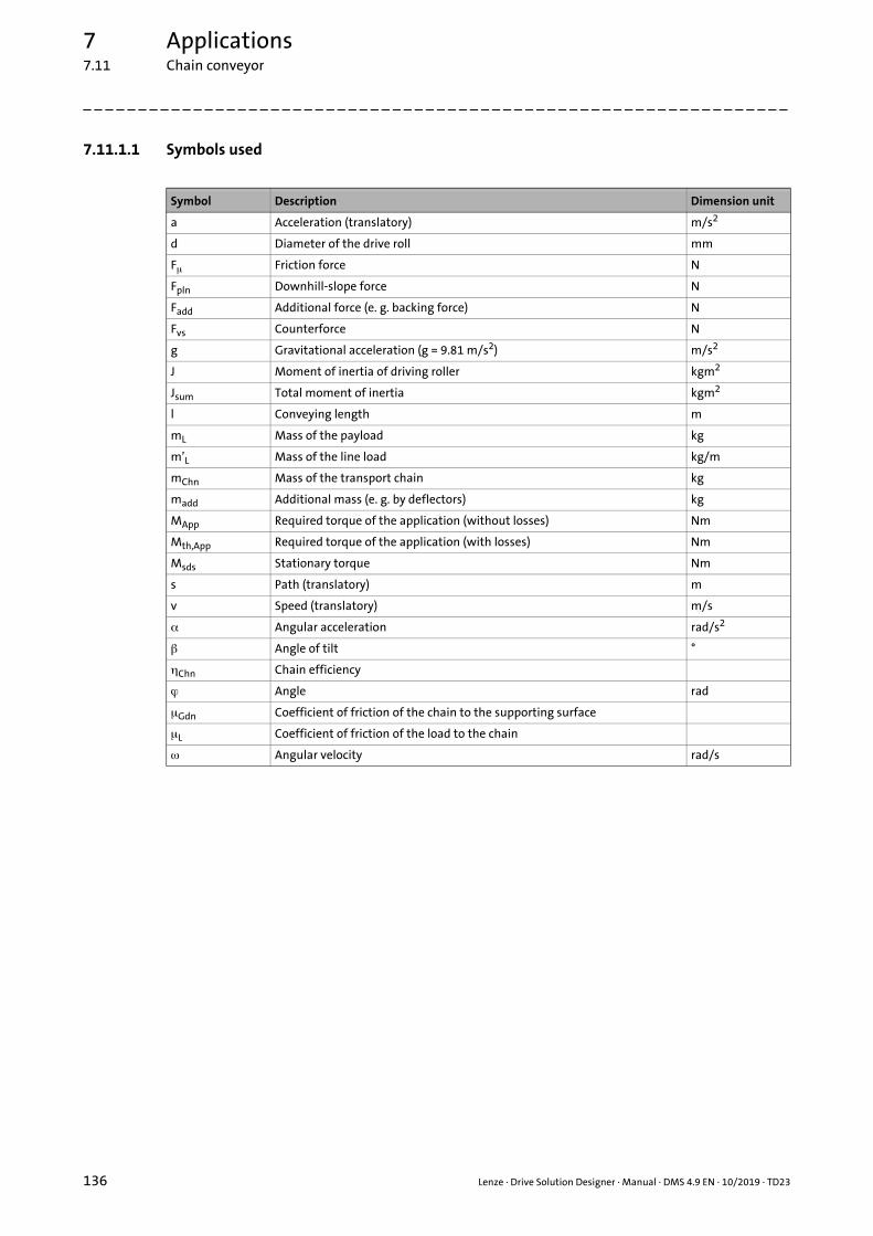
7 Applications7.11 Chain conveyor
_ _ _ _ _ _ _ _ _ _ _ _ _ _ _ _ _ _ _ _ _ _ _ _ _ _ _ _ _ _ _ _ _ _ _ _ _ _ _ _ _ _ _ _ _ _ _ _ _ _ _ _ _ _ _ _ _ _ _ _ _ _ _ _
7.11.1.1 Symbols used
Symbol Description Dimension unit
a Acceleration (translatory) m/s2
d Diameter of the drive roll mm
F Friction force N
Fpln Downhill-slope force N
Fadd Additional force (e. g. backing force) N
Fvs Counterforce N
g Gravitational acceleration (g = 9.81 m/s2) m/s2
J Moment of inertia of driving roller kgm2
Jsum Total moment of inertia kgm2
l Conveying length m
mL Mass of the payload kg
m’L Mass of the line load kg/m
mChn Mass of the transport chain kg
madd Additional mass (e. g. by deflectors) kg
MApp Required torque of the application (without losses) Nm
Mth,App Required torque of the application (with losses) Nm
Msds Stationary torque Nm
s Path (translatory) m
v Speed (translatory) m/s
Angular acceleration rad/s2
Angle of tilt °
Chn Chain efficiency
Angle rad
Gdn Coefficient of friction of the chain to the supporting surface
L Coefficient of friction of the load to the chain
Angular velocity rad/s
136 Lenze · Drive Solution Designer · Manual · DMS 4.9 EN · 10/2019 · TD23

7 Applications7.11 Chain conveyor
_ _ _ _ _ _ _ _ _ _ _ _ _ _ _ _ _ _ _ _ _ _ _ _ _ _ _ _ _ _ _ _ _ _ _ _ _ _ _ _ _ _ _ _ _ _ _ _ _ _ _ _ _ _ _ _ _ _ _ _ _ _ _ _
7.11.2 Data for the entry
7.11.2.1 Diameter of the drive roll
7.11.2.2 Mass of the chain
7.11.2.3 Coefficient of friction of chain/supporting surface
7.11.2.4 Chain efficiency
7.11.2.5 Moment of inertia of driving roller
7.11.2.6 Additional force
Parameter Description
d Outside diameter of drive roll
Parameter Description
mChn Mass of transport chain• Value can be entered directly or calculated by the uniform load and conveying length.
"Uniform load mass (material handling technology)" calculator ( 477)
Parameter Description
μGdn Coefficient of friction between transport chain and supporting surface• Value can be entered directly or selected from the "Physical coefficients" table.Physical coefficients ( 485)
Coefficient of friction for rolls
Parameter Description
Chn Efficiency of the transport chainChn = 0.90 - 0.96 (depending on the chain size)
Parameter Description
J Moment of inertia of the drive roll and all rolls that may be available• Has an impact on the dynamic torque!• Value can be entered directly or calculated using the inertial calculator.
Inertial calculator ( 469)
Parameter Description
Fadd The additional force results from backing forces, lateral friction, deflectors, etc.• The backing force can be calculated using the auxiliary calculator.
"Backing force (material handling technology)" calculator ( 480)
Lenze · Drive Solution Designer · Manual · DMS 4.9 EN · 10/2019 · TD23 137

7 Applications7.11 Chain conveyor
_ _ _ _ _ _ _ _ _ _ _ _ _ _ _ _ _ _ _ _ _ _ _ _ _ _ _ _ _ _ _ _ _ _ _ _ _ _ _ _ _ _ _ _ _ _ _ _ _ _ _ _ _ _ _ _ _ _ _ _ _ _ _ _
7.11.2.7 Angle of tilt
Application with a slope (slide)
For the angle of tilt, only a positive value (slope) can be entered. However, you can dimension anapplication with a slope by specifying a negative speed. If the application is moving on a slope witha negative speed, it goes backwards.
Procedure:
• Enter the value of the slope into the Angle of tilt input field.
• Enter the value with a negative sign into the Speed input field.
7.11.2.8 Speed
7.11.2.9 Mass of the payload
Parameter Description
Angle of tilt (gradient)• The value can be entered in degrees or as a percentage.
Parameter Description
v Speed of the transport chain• Value is entered in the Motion dimensioning step.
Parameter Description
mL Mass of payload• Value is entered in the Motion dimensioning step.
138 Lenze · Drive Solution Designer · Manual · DMS 4.9 EN · 10/2019 · TD23

7 Applications7.12 Roller conveyor
_ _ _ _ _ _ _ _ _ _ _ _ _ _ _ _ _ _ _ _ _ _ _ _ _ _ _ _ _ _ _ _ _ _ _ _ _ _ _ _ _ _ _ _ _ _ _ _ _ _ _ _ _ _ _ _ _ _ _ _ _ _ _ _
7.12 Roller conveyor
Roller conveyors are multi-purpose conveyors for the transport of small unit loads like for exampletanks, cardboard boxes, boxes and packages, and greater material to be conveyed, e. g. pallets andcontainers. They are suitable for transport, buffering (accumulating roller conveyors), and inconnection with supplementary devices for the distribution of piece goods. The load is transportedby means of transport rolls, which are interconnected by a chain, belt, or strap. Like belt conveyors,roller conveyors can be designed with an end drive or centre drive in the form of a geared motor.Alternatively there is the possibility of directly actuating individual rolls via a tubular roller motor,in the case of which the motor is directly integrated within the roll.
7.12.1 Calculations
For a roller conveyor according to the drawing the following applies:
Conversion of translatory variables into rotary variables
[7-120] Equation 1: Angle
[7-121] Equation 2: Angular velocity
[7-122] Equation 3: Angular acceleration
Total moment of inertia
[7-123] Equation 4: Total moment of inertia
2000 sd
--------------------=
2000 vd
--------------------=
2000 ad
--------------------=
Jsum mLd2--- 2
J+=
Lenze · Drive Solution Designer · Manual · DMS 4.9 EN · 10/2019 · TD23 139

7 Applications7.12 Roller conveyor
_ _ _ _ _ _ _ _ _ _ _ _ _ _ _ _ _ _ _ _ _ _ _ _ _ _ _ _ _ _ _ _ _ _ _ _ _ _ _ _ _ _ _ _ _ _ _ _ _ _ _ _ _ _ _ _ _ _ _ _ _ _ _ _
Stationary torque
The stationary part of the torque consists of different individual forces:
[7-124] Equation 5: Stationary torque
Friction force
In relation to the payload, the mass of the rollers is largely low. Its share in the friction force canusually be neglected and is therefore not taken into consideration in the DSD. If, in individual cases,the mass of the rollers constitutes a significant proportion in relation to the payload, a manualcalculation is to be added to the drive dimensioning as correction.
[7-125] Equation 6: Friction force
Downhill-slope force
[7-126] Equation 7: Downhill-slope force
Additional force (e. g. backing force)
If the transported material drives against a limit stop (e. g. for adjustment, the force Fadd isgenerated.
If the mass of the rollers has to be considered as the mass of the material to be conveyed is relativelysmall, the resulting friction force can be entered as additional force Fadd.
[7-127] Equation 8: Additional force
Mass of payload
The mass of the payload is calculated by the line load:
[7-128] Equation 9: Mass of the payload
Msds F Fpln Fadd+ + d2---=
FmL g cos
d-------------------------------- 2f d+ Brg Brg
------- =
Fpln mL g sin =
Fadd madd g cos Lvv----- =
mL m’L l=
140 Lenze · Drive Solution Designer · Manual · DMS 4.9 EN · 10/2019 · TD23

7 Applications7.12 Roller conveyor
_ _ _ _ _ _ _ _ _ _ _ _ _ _ _ _ _ _ _ _ _ _ _ _ _ _ _ _ _ _ _ _ _ _ _ _ _ _ _ _ _ _ _ _ _ _ _ _ _ _ _ _ _ _ _ _ _ _ _ _ _ _ _ _
Required torque of the application (without losses)
In order to take the efficiency of the application by the transmission of the movement via chainsinto consideration, first the required torque of the application has to be determined:
[7-129] Equation 10: Required torque of the application (without losses)
Required torque of the application (with losses)
Provided that the friction torque of the application is proportional to the transmitting torque, therequired torque of the application can be calculated with the following equation:
[7-130] Equation 11: Required torque of the application (with losses)
[7-131] Equation 11: Total chain efficiency
Tip!
Further equations to complete the calculations required for an application can be found inthe chapter "Basic calculations". ( 67)
MApp Msds Jsum +=
Mth,App MApp MApp------- 1
sum------------- 1– +=
sum Chnn=
Lenze · Drive Solution Designer · Manual · DMS 4.9 EN · 10/2019 · TD23 141

7 Applications7.12 Roller conveyor
_ _ _ _ _ _ _ _ _ _ _ _ _ _ _ _ _ _ _ _ _ _ _ _ _ _ _ _ _ _ _ _ _ _ _ _ _ _ _ _ _ _ _ _ _ _ _ _ _ _ _ _ _ _ _ _ _ _ _ _ _ _ _ _
7.12.1.1 Symbols used
7.12.2 Data for the entry
7.12.2.1 Diameter of the transport rolls
Symbol Description Dimension unit
d Diameter of the transport rolls mm
dBrg Diameter of the bearings mm
f Lever arm of the rolling friction mm
F Friction force N
Fpln Downhill-slope force N
Fadd Additional force (e. g. backing force) N
g Gravitational acceleration (g = 9.81 m/s2) m/s2
J Moment of inertia of transport rollers kgm2
Jsum Total moment of inertia kgm2
l Conveying length m
mL Mass of the payload kg
m’L Mass of the line load kg/m
madd Additional mass (e. g. by deflectors) kg
MApp Required torque of the application (without losses) Nm
Mth,App Required torque of the application (with losses) Nm
Msds Stationary torque Nm
s Path (translatory) m
v Speed (translatory) m/s
Angular velocity (rotatory) rad/s
a Acceleration (translatory) m/s2
Angular acceleration (rotatory) rad/s2
Angle of tilt °
sum Total chain efficiency
Chn Efficiency of one chain
Angle rad
L Coefficient of friction of the load/roll
Brg Coefficient of friction of the bearing
Parameter Description
d Outside diameter of feed rolls
142 Lenze · Drive Solution Designer · Manual · DMS 4.9 EN · 10/2019 · TD23

7 Applications7.12 Roller conveyor
_ _ _ _ _ _ _ _ _ _ _ _ _ _ _ _ _ _ _ _ _ _ _ _ _ _ _ _ _ _ _ _ _ _ _ _ _ _ _ _ _ _ _ _ _ _ _ _ _ _ _ _ _ _ _ _ _ _ _ _ _ _ _ _
7.12.2.2 Leverage of rolling friction
[7-132] Principle of the rolling friction
7.12.2.3 Chain efficiency
Parameter Description
f The lever arm of the rolling friction serves to calculate the friction force.• Value can be entered directly or selected from the "Physical coefficients" table.Physical coefficients ( 485)
Lever arm of the rolling friction
f Lever arm of the rolling friction
Fμf Rolling friction (absolute value)
Fn Pinch pressure of rollers
v Speed
hr
µ�
f
Fµf
v
Fn
Parameter Description
Chn Values for the efficiency Chn per complete wrap:Chain = 0.90 - 0.96 (depending on the chain size)Toothed belt = 0.96 - 0.98 (depending on the material)Flat belt = 0.93 - 0.98 (depending on the material)V-belt = 0.88 - 0.95Rubber strap = 0.80 - 0.85Non-metallic strap = 0.80 - 0.85Wire rope = 0.90 - 0.95
Note!
When the power is transmitted from the drive to the transport rollers, the efficiency Chn of the chain is reduced with every chain wrap.
• The efficiency Chn exponentiates with the number of chain wraps NChn.
• Position the drive centrally if necessary to distribute the power transmission to two paths. That way, the number of chain wraps per path is also reduced.
• Realistic values must be assumed for the efficiency Chn.
Lenze · Drive Solution Designer · Manual · DMS 4.9 EN · 10/2019 · TD23 143

7 Applications7.12 Roller conveyor
_ _ _ _ _ _ _ _ _ _ _ _ _ _ _ _ _ _ _ _ _ _ _ _ _ _ _ _ _ _ _ _ _ _ _ _ _ _ _ _ _ _ _ _ _ _ _ _ _ _ _ _ _ _ _ _ _ _ _ _ _ _ _ _
7.12.2.4 Bearing diameter
7.12.2.5 Moment of inertia of transport rollers
7.12.2.6 Number of wrapped chain turns
7.12.2.7 Additional force
Parameter Description
dBrg The diameter for calculating the bearing friction.
Parameter Description
J Moment of inertia of the transport rolls, shafts, etc.• Has an impact on the dynamic torque!• Value can be entered directly or calculated using the inertial calculator.
Inertial calculator ( 469)
Parameter Description
NChn • Number of chain wraps which distribute the torque to the single rolls. For calculation, the most unfavourable efficiency is assumed (load is applied to the last driven roll).
Note!
When the power is transmitted from the drive to the transport rollers, the efficiency Chn of the chain is reduced with every chain wrap.
• The efficiency Chn exponentiates with the number of chain wraps NChn.
• Position the drive centrally if necessary to distribute the power transmission to two paths. That way, the number of chain wraps per path is also reduced.
• Realistic values must be assumed for the efficiency Chn.
Parameter Description
Fadd The additional force results from backing forces, lateral friction, deflectors, etc.• The backing force can be calculated using the auxiliary calculator.
"Backing force (material handling technology)" calculator ( 480)
Note!
If the mass of the rollers has to be considered as the mass of the material to be conveyed is relatively small, the resulting friction force can be entered as additional force Fadd.
Additional force (e. g. backing force)
144 Lenze · Drive Solution Designer · Manual · DMS 4.9 EN · 10/2019 · TD23

7 Applications7.12 Roller conveyor
_ _ _ _ _ _ _ _ _ _ _ _ _ _ _ _ _ _ _ _ _ _ _ _ _ _ _ _ _ _ _ _ _ _ _ _ _ _ _ _ _ _ _ _ _ _ _ _ _ _ _ _ _ _ _ _ _ _ _ _ _ _ _ _
7.12.2.8 Angle of tilt
Application with a slope (slide)
For the angle of tilt, only a positive value (slope) can be entered. However, you can dimension anapplication with a slope by specifying a negative speed. If the application is moving on a slope witha negative speed, it goes backwards.
Procedure:
• Enter the value of the slope into the Angle of tilt input field.
• Enter the value with a negative sign into the Speed input field.
7.12.2.9 Coefficient of friction of the bearing
7.12.2.10 Speed
7.12.2.11 Mass of the payload
Parameter Description
Angle of tilt (gradient)• The value can be entered in degrees or as a percentage.• The max. angle of tilt as a first approximation is: arctan(μL)
(static friction between load and roll).
Parameter Description
μBrg Coefficient of friction for the bearing friction• Value can be entered directly or selected from the "Physical coefficients" table.Physical coefficients ( 485)
Bearing and leadscrew friction
Parameter Description
v Speed of the goods to be conveyed• Value is entered in the Motion dimensioning step.
Parameter Description
mL Mass of payload• Value is entered in the Motion dimensioning step.
Lenze · Drive Solution Designer · Manual · DMS 4.9 EN · 10/2019 · TD23 145

7 Applications7.13 Belt conveyor, unit load
_ _ _ _ _ _ _ _ _ _ _ _ _ _ _ _ _ _ _ _ _ _ _ _ _ _ _ _ _ _ _ _ _ _ _ _ _ _ _ _ _ _ _ _ _ _ _ _ _ _ _ _ _ _ _ _ _ _ _ _ _ _ _ _
7.13 Belt conveyor, unit load
A belt conveyor for unit loads transports the material to be conveyed (e. g. boxes, pallets) by meansof a transport belt. Because of the smooth surface it is suitable for different sizes of unit loads andunstable packaged goods. Basic features are the smooth and noiseless running and the carefultransport of goods. Depending on the material to be conveyed, belt conveyors can usually be usedfor slopes of up to 20°, in individual cases and with specific designs even for slopes up to 60. .°
In the upper strand the conveying belt slides on a surface, in the lower strand it can be guided byrolls. In the lower strand usually also the belt is tightened by means of a clamping device orclamping unit in the form of guide pulleys that can be shifted. The power transmission between thebelt and drive roll is effected by means of adhesion.
With regard to the mounting position of the drive, end drives (position at the end, below the belt,or at the side next to the belt) and centre drives (position in the centre, below the belt) aredifferentiated. In the case of the end drive that is located at the side usually a bevel gearbox orhelical-bevel gearbox is used. The output shaft of the gearbox directly actuates the drive roll. In thecase of the end drive that is located below the belt predominantly helical gearboxes are used andthe drive roll is actuated by means of belts.
7.13.1 Calculations
For a belt conveyor for unit loads according to the drawing the following applies:
Total moment of inertia
[7-133] Equation 1: Total moment of inertia
Jsum maux mBlt+ d2--- 2
Jaux+=
146 Lenze · Drive Solution Designer · Manual · DMS 4.9 EN · 10/2019 · TD23

7 Applications7.13 Belt conveyor, unit load
_ _ _ _ _ _ _ _ _ _ _ _ _ _ _ _ _ _ _ _ _ _ _ _ _ _ _ _ _ _ _ _ _ _ _ _ _ _ _ _ _ _ _ _ _ _ _ _ _ _ _ _ _ _ _ _ _ _ _ _ _ _ _ _
Stationary torque
The stationary part of the torque consists of different individual forces:
[7-134] Equation 2: Stationary torque
[7-135] Equation 3: Friction force
[7-136] Equation 4: Lifting force
If the transported material drives against a limit stop (e. g. adjustment of the material), the forceFadd is generated:
[7-137] Equation 5: Additional force
The friction of the rolls is taken into consideration by the friction force Faux:
[7-138] Equation 6: Friction force by run via rolls
The mass of the payload is calculated by the line load:
[7-139] Equation 7: Mass of the payload
Required torque of the application (without losses)
[7-140] Equation 8: Required torque of the application (without losses)
Tip!
Further equations to complete the calculations required for an application can be found inthe chapter "Basic calculations". ( 67)
Msds F Fpln Fadd Faux+ + + d2---=
F mL
mBlt
2-----------+
g Gdn cosvv----- =
Fpln mL g sin =
Fadd madd g – sincos
-------------------------- vv----- arctan L= =
Faux maux
mBlt
2-----------+
g auxvv----- =
mL m’L l=
MApp Msds Jsum +=
Lenze · Drive Solution Designer · Manual · DMS 4.9 EN · 10/2019 · TD23 147
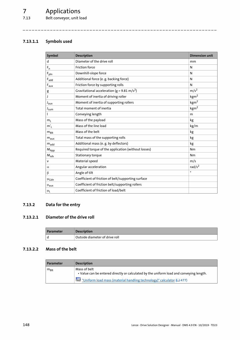
7 Applications7.13 Belt conveyor, unit load
_ _ _ _ _ _ _ _ _ _ _ _ _ _ _ _ _ _ _ _ _ _ _ _ _ _ _ _ _ _ _ _ _ _ _ _ _ _ _ _ _ _ _ _ _ _ _ _ _ _ _ _ _ _ _ _ _ _ _ _ _ _ _ _
7.13.1.1 Symbols used
7.13.2 Data for the entry
7.13.2.1 Diameter of the drive roll
7.13.2.2 Mass of the belt
Symbol Description Dimension unit
d Diameter of the drive roll mm
F Friction force N
Fpln Downhill-slope force N
Fadd Additional force (e. g. backing force) N
Faux Friction force by supporting rolls N
g Gravitational acceleration (g = 9.81 m/s2) m/s2
J Moment of inertia of driving roller kgm2
Jaux Moment of inertia of supporting rollers kgm2
Jsum Total moment of inertia kgm2
l Conveying length m
mL Mass of the payload kg
m’L Mass of the line load kg/m
mBlt Mass of the belt kg
maux Total mass of the supporting rolls kg
madd Additional mass (e. g. by deflectors) kg
MApp Required torque of the application (without losses) Nm
Msds Stationary torque Nm
v Material speed m/s
Angular acceleration rad/s2
Angle of tilt °
Gdn Coefficient of friction of belt/supporting surface
aux Coefficient of friction belt/supporting rollers
L Coefficient of friction of load/belt
Parameter Description
d Outside diameter of drive roll
Parameter Description
mBlt Mass of belt• Value can be entered directly or calculated by the uniform load and conveying length.
"Uniform load mass (material handling technology)" calculator ( 477)
148 Lenze · Drive Solution Designer · Manual · DMS 4.9 EN · 10/2019 · TD23

7 Applications7.13 Belt conveyor, unit load
_ _ _ _ _ _ _ _ _ _ _ _ _ _ _ _ _ _ _ _ _ _ _ _ _ _ _ _ _ _ _ _ _ _ _ _ _ _ _ _ _ _ _ _ _ _ _ _ _ _ _ _ _ _ _ _ _ _ _ _ _ _ _ _
7.13.2.3 Mass of supporting rollers
7.13.2.4 Moment of inertia of rollers
7.13.2.5 Additional force
Parameter Description
maux Total mass of supporting rolls• If aux = 0, the friction by the supporting rolls is disregarded, a value for the mass then does
not have to be entered.• Value can be entered directly or calculated using the mass calculator.
Mass calculator ( 467)
Note!
The mass of the supporting rolls is used for calculating the friction forces.
Parameter Description
Jsum Moment of inertia of the drive roll and all supporting rolls.• Has an impact on the dynamic torque!• Value can be entered directly or calculated using the inertial calculator.
Inertial calculator ( 469)
Note!
When calculating the mass inertia, bear in mind that the supporting rolls and the drive roll can have different diameters!
Parameter Description
Fadd The additional force results from backing forces, lateral friction, deflectors, etc.• The backing force can be calculated using the auxiliary calculator.
"Backing force (material handling technology)" calculator ( 480)
Lenze · Drive Solution Designer · Manual · DMS 4.9 EN · 10/2019 · TD23 149

7 Applications7.13 Belt conveyor, unit load
_ _ _ _ _ _ _ _ _ _ _ _ _ _ _ _ _ _ _ _ _ _ _ _ _ _ _ _ _ _ _ _ _ _ _ _ _ _ _ _ _ _ _ _ _ _ _ _ _ _ _ _ _ _ _ _ _ _ _ _ _ _ _ _
7.13.2.6 Angle of tilt
Application with a slope (slide)
For the angle of tilt, only a positive value (slope) can be entered. However, you can dimension anapplication with a slope by specifying a negative speed. If the application is moving on a slope witha negative speed, it goes backwards.
Procedure:
• Enter the value of the slope into the Angle of tilt input field.
• Enter the value with a negative sign into the Speed input field.
7.13.2.7 Coefficient of friction belt/supporting surface
7.13.2.8 Coefficient of friction belt/supporting rollers
7.13.2.9 Speed
7.13.2.10 Mass of the payload
Parameter Description
Angle of tilt (gradient)• The value can be entered in degrees or as a percentage.• The max. angle of tilt as a first approximation is: arctan arctan(μL)(static friction between
load and belt).
Parameter Description
μGdn Coefficient of friction between the belt and the supporting surface• Value can be entered directly or selected from the "Physical coefficients" table.Physical coefficients ( 485)
Coefficient of friction for rolls
Parameter Description
μaux Coefficient of friction between the supporting rolls and the belt• If aux = 0, the friction by the supporting rolls is disregarded.• Value can be entered directly or selected from the "Physical coefficients" table.Physical coefficients ( 485)
Coefficient of friction for rolls
Parameter Description
v Speed of the belt• Value is entered in the Motion dimensioning step.
Parameter Description
mL Mass of payload• Value is entered in the Motion dimensioning step.
150 Lenze · Drive Solution Designer · Manual · DMS 4.9 EN · 10/2019 · TD23

7 Applications7.14 Belt conveyor, bulk material
_ _ _ _ _ _ _ _ _ _ _ _ _ _ _ _ _ _ _ _ _ _ _ _ _ _ _ _ _ _ _ _ _ _ _ _ _ _ _ _ _ _ _ _ _ _ _ _ _ _ _ _ _ _ _ _ _ _ _ _ _ _ _ _
7.14 Belt conveyor, bulk material
The belt conveyor for bulk material transports the material to be conveyed by means of rotatingconveyor belts with tension carriers of a fabric or steel cable reinforcement and a rubber or plasticcover. The conveyor belts are supported by idlers and are actuated or decelerated via drums bymeans of friction. These conveyors are often designed as trough conveyors or pipe conveyors.
7.14.1 Calculations
For a belt conveyor for bulk material according to the drawing the following applies:
Total moment of inertia
[7-141] Equation 1: Total moment of inertia
Stationary torque
The stationary part of the torque consists of different individual forces:
[7-142] Equation 2: Stationary torque
The conveying force is calculated by the line loads, the conveying length, and the filling factor f (thecoefficient is a fictitious value):
[7-143] Equation 3: Conveying force
[7-144] Equation 4: Line load of the payload
Jsum mL mBlt+ d2--- 2
J Jaux+ +=
Msds Fopr Fpln Fadd+ + d2---=
Fopr l fBlt g m’aux 2 m’Blt m’L+ vv-----cos+
=
m’L
mL
l------- mL
Q
v 3600 /s h---------------------------- l==
Lenze · Drive Solution Designer · Manual · DMS 4.9 EN · 10/2019 · TD23 151
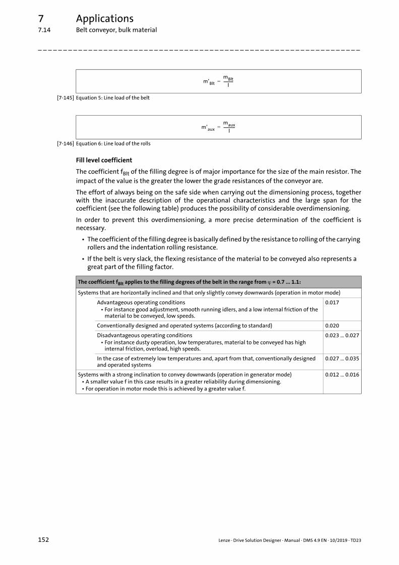
7 Applications7.14 Belt conveyor, bulk material
_ _ _ _ _ _ _ _ _ _ _ _ _ _ _ _ _ _ _ _ _ _ _ _ _ _ _ _ _ _ _ _ _ _ _ _ _ _ _ _ _ _ _ _ _ _ _ _ _ _ _ _ _ _ _ _ _ _ _ _ _ _ _ _
[7-145] Equation 5: Line load of the belt
[7-146] Equation 6: Line load of the rolls
Fill level coefficient
The coefficient fBlt of the filling degree is of major importance for the size of the main resistor. Theimpact of the value is the greater the lower the grade resistances of the conveyor are.
The effort of always being on the safe side when carrying out the dimensioning process, togetherwith the inaccurate description of the operational characteristics and the large span for thecoefficient (see the following table) produces the possibility of considerable overdimensioning.
In order to prevent this overdimensioning, a more precise determination of the coefficient isnecessary.
• The coefficient of the filling degree is basically defined by the resistance to rolling of the carrying rollers and the indentation rolling resistance.
• If the belt is very slack, the flexing resistance of the material to be conveyed also represents a great part of the filling factor.
m’Blt
mBlt
l-----------=
m’aux
maux
l-------------=
The coefficient fBlt applies to the filling degrees of the belt in the range from = 0.7 ... 1.1:
Systems that are horizontally inclined and that only slightly convey downwards (operation in motor mode)
Advantageous operating conditions• For instance good adjustment, smooth running idlers, and a low internal friction of the
material to be conveyed, low speeds.
0.017
Conventionally designed and operated systems (according to standard) 0.020
Disadvantageous operating conditions• For instance dusty operation, low temperatures, material to be conveyed has high
internal friction, overload, high speeds.
0.023 … 0.027
In the case of extremely low temperatures and, apart from that, conventionally designed and operated systems
0.027 … 0.035
Systems with a strong inclination to convey downwards (operation in generator mode)• A smaller value f in this case results in a greater reliability during dimensioning.• For operation in motor mode this is achieved by a greater value f.
0.012 … 0.016
152 Lenze · Drive Solution Designer · Manual · DMS 4.9 EN · 10/2019 · TD23

7 Applications7.14 Belt conveyor, bulk material
_ _ _ _ _ _ _ _ _ _ _ _ _ _ _ _ _ _ _ _ _ _ _ _ _ _ _ _ _ _ _ _ _ _ _ _ _ _ _ _ _ _ _ _ _ _ _ _ _ _ _ _ _ _ _ _ _ _ _ _ _ _ _ _
The filling degree is the ratio of the actual to the theoretically filled surface of the belt:
[7-147] Equation 7: Filling degree
[7-148] Equation 8: Downhill-slope force
The additional force takes the frictional resistance and inertial resistance occurring in differentpositions of the belt conveyor into consideration:
[7-149] Equation 9: Additional force
• The additional force (Fadd) results from:
• The inertial and frictional resistance between the material to be conveyed and the belt at the feeding position
• Frictional resistance between the material to be conveyed and lateral chutes• Frictional resistance by the belt cleaner• Flexural resistance of the belt
Required torque of the application
[7-150] Equation 10: Torque of the application
Tip!
Further equations to complete the calculations required for an application can be found inthe chapter "Basic calculations". ( 67)
Aopr
Aabt-----------=
Fpln mL g sin =
Fadd C 1– Fopr=
Shunt-force factor CThe coefficients f apply to filling degrees of the belt in the range of = 0.7 ... 1.1:
l [m] 80 100 150 200 300 400 500 600 700 800 900 1000 1500 > 2000
C 1.92 1.78 1.58 1.45 1.31 1.25 1.20 1.17 1.14 1.12 1.10 1.09 1.06 1.05
MApp Msds Jsum +=
Lenze · Drive Solution Designer · Manual · DMS 4.9 EN · 10/2019 · TD23 153

7 Applications7.14 Belt conveyor, bulk material
_ _ _ _ _ _ _ _ _ _ _ _ _ _ _ _ _ _ _ _ _ _ _ _ _ _ _ _ _ _ _ _ _ _ _ _ _ _ _ _ _ _ _ _ _ _ _ _ _ _ _ _ _ _ _ _ _ _ _ _ _ _ _ _
7.14.1.1 Symbols used
7.14.2 Data for the entry
7.14.2.1 Diameter of the drive roll
7.14.2.2 Length of conveyor line
Symbol Description Dimension unit
Aopr Filling cross-section of the belt M2
Aabt Theoretical filling cross-section of the belt M2
C Shunt-force factor
d Diameter of the drive roll mm
Fadd Additional force N
fBlt Filling factor
Fopr Conveying force N
Fpln Downhill-slope force N
g Gravitational acceleration (g = 9.81 m/s2) m/s2
J Moment of inertia of driving roller kgm2
Jaux Moment of inertia of supporting rollers kgm2
Jsum Total moment of inertia kgm2
l Conveying length m
mL Mass of payload kg
m’L Line load of the payload kg/m
mBlt Mass of the belt kg
m’Blt Line load of the belt kg/m
maux Mass of the supporting rolls kg
m’aux Line load of the supporting rolls kg/m
MApp Required torque of the application Nm
Msds Stationary torque Nm
Q Delivery rate kg/h
v Speed of the belt m/s
Angular acceleration rad/s2
Angle of tilt °
Parameter Description
d Outside diameter of drive roll
Parameter Description
l Total conveying length
154 Lenze · Drive Solution Designer · Manual · DMS 4.9 EN · 10/2019 · TD23

7 Applications7.14 Belt conveyor, bulk material
_ _ _ _ _ _ _ _ _ _ _ _ _ _ _ _ _ _ _ _ _ _ _ _ _ _ _ _ _ _ _ _ _ _ _ _ _ _ _ _ _ _ _ _ _ _ _ _ _ _ _ _ _ _ _ _ _ _ _ _ _ _ _ _
7.14.2.3 Mass of the payload
7.14.2.4 Mass of the belt
7.14.2.5 Angle of tilt
Application with a slope (slide)
For the angle of tilt, only a positive value (slope) can be entered. However, you can dimension anapplication with a slope by specifying a negative speed. If the application is moving on a slope witha negative speed, it goes backwards.
Procedure:
• Enter the value of the slope into the Angle of tilt input field.
• Enter the value with a negative sign into the Speed input field.
7.14.2.6 Fill level coefficient
Parameter Description
mL Mass of payload• Value can be entered directly or calculated by the uniform load and conveying length.
"Uniform load mass (material handling technology)" calculator ( 477)
Parameter Description
mBlt Mass of belt• Value can be entered directly or calculated by the uniform load and conveying length.
"Uniform load mass (material handling technology)" calculator ( 477)
Parameter Description
Angle of tilt (gradient)• The value can be entered in degrees or as a percentage.• The max. angle of tilt as a first approximation is: arctan(μ)
(static friction between load and surface).
Parameter Description
fBlt Filling factor• The guide value applies to filling degress of the belt from 0.7 ... 1.1.• Value can be entered directly or selected from the "Physical coefficients" table.Fill level coefficient ( 152) Physical coefficients ( 485)
Filling factor for belt conveyors
Lenze · Drive Solution Designer · Manual · DMS 4.9 EN · 10/2019 · TD23 155

7 Applications7.14 Belt conveyor, bulk material
_ _ _ _ _ _ _ _ _ _ _ _ _ _ _ _ _ _ _ _ _ _ _ _ _ _ _ _ _ _ _ _ _ _ _ _ _ _ _ _ _ _ _ _ _ _ _ _ _ _ _ _ _ _ _ _ _ _ _ _ _ _ _ _
7.14.2.7 Shunt-force coefficient
7.14.2.8 Mass of supporting rollers
7.14.2.9 Moment of inertia of driving roller
Parameter Description
C Shunt-force factor• The sum of all the peripheral resistances, such as belt bending resistance, friction resistance
from chutes, belt cleaners etc. is taken into consideration in this factor.• Value can be entered directly or selected from the "Physical coefficients" table.Physical coefficients ( 485)
Shunt-force factor C
Parameter Description
maux Total mass of supporting rolls• If aux = 0, the friction by the guide pulleys and guide rollers is disregarded, a value for the
mass then does not have to be entered.• Value can be entered directly or calculated using the mass calculator.
Mass calculator ( 467)
Note!
The mass of the supporting rolls is used for calculating the friction forces.
Parameter Description
J Moment of inertia of the drive roll• Value can be entered directly or calculated using the inertial calculator.
Inertial calculator ( 469)
Note!
When calculating the mass inertia, bear in mind that the supporting rolls and the drive roll can have different diameters!Moment of inertia of supporting rollers ( 157)
156 Lenze · Drive Solution Designer · Manual · DMS 4.9 EN · 10/2019 · TD23

7 Applications7.14 Belt conveyor, bulk material
_ _ _ _ _ _ _ _ _ _ _ _ _ _ _ _ _ _ _ _ _ _ _ _ _ _ _ _ _ _ _ _ _ _ _ _ _ _ _ _ _ _ _ _ _ _ _ _ _ _ _ _ _ _ _ _ _ _ _ _ _ _ _ _
7.14.2.10 Moment of inertia of supporting rollers
7.14.2.11 Speed
Parameter Description
Jaux Moment of inertia of the supporting rolls• Value can be entered directly or calculated using the inertial calculator.
Inertial calculator ( 469)
Note!
When calculating the mass inertia, bear in mind that the supporting rolls and the drive roll can have different diameters!Moment of inertia of driving roller ( 156)
Parameter Description
v Speed of the belt• Value is entered in the Motion dimensioning step.
Lenze · Drive Solution Designer · Manual · DMS 4.9 EN · 10/2019 · TD23 157

7 Applications7.15 Synchronous drive - single roll
_ _ _ _ _ _ _ _ _ _ _ _ _ _ _ _ _ _ _ _ _ _ _ _ _ _ _ _ _ _ _ _ _ _ _ _ _ _ _ _ _ _ _ _ _ _ _ _ _ _ _ _ _ _ _ _ _ _ _ _ _ _ _ _
7.15 Synchronous drive - single roll
Synchronous drives are part of the production process of continuous material which is produced orrefined at a high speed. At the starting and end point of these systems they are often combined withwinding drives. Alternatively also cross cutters and flying saws can separate the material at the endof a production line and thus provide the transition from continuous production to a quickly clockedjob production. In production lines the synchronous drives are the most important drives, since theycontrol the material flow and therefore the machining process.
The individual rolls can be equipped with single drives and can be mechanically coupled. Apart fromfactors resulting from fixed mechanical conditions, the torque to be transmitted basically dependson the friction coefficient between the material and roll surface. In application cases where thefriction coefficient can be strongly reduced, e. g. due to pollution, corresponding measures like ananti-spin control within the control structure are to be provided to avoid slip between thecircumferential roller speed and the web.
In order to be able to couple high tensile forces into the web, usually roll arrangements with greatangles of wrap in the form of S- or omega rolls are designed.
Application examples
• Production, refinement of paper or film webs
• Production and refinement of textile webs
• Rolling of slabs, plates
• Rolling, annealing, and refinement of metal plates
• Wire drawing machines
• Printing of paper or film webs, textiles
158 Lenze · Drive Solution Designer · Manual · DMS 4.9 EN · 10/2019 · TD23

7 Applications7.15 Synchronous drive - single roll
_ _ _ _ _ _ _ _ _ _ _ _ _ _ _ _ _ _ _ _ _ _ _ _ _ _ _ _ _ _ _ _ _ _ _ _ _ _ _ _ _ _ _ _ _ _ _ _ _ _ _ _ _ _ _ _ _ _ _ _ _ _ _ _
7.15.1 Calculations
For a synchronous drive with a single roll according to the drawing the following applies:
Conditions
The force ratio always has to be smaller than the static friction to avoid slippage. The forces Fin andFout must not be negative. The safety coefficient S provides for a safety reserve that can beindividually adapted to the application. During the application both a motor torque and aregenerative torque can occur.
For a reliable power transmission from the drive roll to the material the following conditions haveto be met. Otherwise the DSD outputs a message.
[7-151] Equation 1: Balance of forces
Stationary torque
Under the previously mentioned conditions the stationary torque of the roll is calculated as follows:
[7-152] Equation 2: Stationary torque
Friction torque
In order to take the friction into consideration, usually a system efficiency is specified. Since thefriction torque is a torque that is constantly applied, a friction torque M is calculated by means ofthe efficiency and the max. steady-state torque, which is then taken into consideration as aconstant torque.
• The direction of the friction torque is always opposed to the direction of movement and is expressed mathematically by the fraction v/|v|.
[7-153] Equation 3: Friction torque
Moment of inertia
The total moment of inertia consists of the moments of inertia of the individual components:
[7-154] Equation 4: Total moment of inertia
For the motor torque ( Fin > Fout): For the regenerative torque (Fin < Fout):
Fin
Fout------------- e
0 1 S
100---------–
Fout
Fin------------- e
0 1 S
100---------–
Msds
Fin Fout– d
1000 2------------------------------------=
M1
Brg---------- 1– max Msds
vv----- =
Jsum J JL+=
Lenze · Drive Solution Designer · Manual · DMS 4.9 EN · 10/2019 · TD23 159

7 Applications7.15 Synchronous drive - single roll
_ _ _ _ _ _ _ _ _ _ _ _ _ _ _ _ _ _ _ _ _ _ _ _ _ _ _ _ _ _ _ _ _ _ _ _ _ _ _ _ _ _ _ _ _ _ _ _ _ _ _ _ _ _ _ _ _ _ _ _ _ _ _ _
Application torque
[7-155] Equation 5: Torque of the application
Tip!
Further equations to complete the calculations required for an application can be found inthe chapter "Basic calculations". ( 67)
7.15.1.1 Symbols used
7.15.2 Data for the entry
7.15.2.1 Roll diameter
MApp Msds M Jsum + +=
Symbol Description Dimension unit
d Diameter of the drive roll mm
Fin Tension on input side (only positive tensile forces possible) N
Fout Tension on output side (only positive tensile forces possible) N
J Moment of inertia of the drive roll kgm2
JL Moment of inertia of the effective mass of the material to be conveyed kgm2
Jsum Total moment of inertia (rolls/material) kgm2
S Safety coefficient for the static friction %
MApp Required torque of the application Nm
M Friction torque Nm
Msds Stationary torque Nm
v Speed of the material m/min
Angle of wrap °
Brg Mechanical efficiency of the roll bearing
μ0 Coefficient of friction of the roll surface
Parameter Description
d Outside diameter of drive roll
160 Lenze · Drive Solution Designer · Manual · DMS 4.9 EN · 10/2019 · TD23

7 Applications7.15 Synchronous drive - single roll
_ _ _ _ _ _ _ _ _ _ _ _ _ _ _ _ _ _ _ _ _ _ _ _ _ _ _ _ _ _ _ _ _ _ _ _ _ _ _ _ _ _ _ _ _ _ _ _ _ _ _ _ _ _ _ _ _ _ _ _ _ _ _ _
7.15.2.2 Tensile force, infeed
7.15.2.3 Tensile force, outfeed
7.15.2.4 Efficiency, roll mechanics
7.15.2.5 Moment of inertia, rolls/material
Parameter Description
Fin The tensile force on the material belt at the input side of the roll, i.e. where the material approaches the roll.
• Only positive values possible.• The difference in force between the input side and the output side has to be provided by the
drive.
Possible messages
Ratio of the tensile forces Fin / Fout > limit value ( 503) Ratio of the tensile forces Fout / Fin > limit value ( 503)
Parameter Description
Fout The tensile force on the material belt at the output side of the roll, i.e. where the material moves away from the roll.
• Only positive values possible.• The difference in force between the input side and the output side has to be provided by the
drive.
Possible messages
Ratio of the tensile forces Fin / Fout > limit value ( 503) Ratio of the tensile forces Fout / Fin > limit value ( 503)
Parameter Description
Brg Efficiency• Takes into account the overall mechanical losses, e.g. those resulting from friction between
the material belt and the roller or serrations on the roller.
Parameter Description
J Moment of inertia of the drive roll of the material to be conveyed (if relevant), etc.• The moment of inertia has an effect on the dynamic torque!• Value can be entered directly or calculated using the inertial calculator.
Inertial calculator ( 469)
Lenze · Drive Solution Designer · Manual · DMS 4.9 EN · 10/2019 · TD23 161

7 Applications7.15 Synchronous drive - single roll
_ _ _ _ _ _ _ _ _ _ _ _ _ _ _ _ _ _ _ _ _ _ _ _ _ _ _ _ _ _ _ _ _ _ _ _ _ _ _ _ _ _ _ _ _ _ _ _ _ _ _ _ _ _ _ _ _ _ _ _ _ _ _ _
7.15.2.6 Static friction coefficient of roll surface
7.15.2.7 Angle of wrap
Parameter Description
μ0 Static friction coefficient• The power transmission between the roll and the web is effected by friction. The coefficient
of static friction specifies how great the force to be transmitted can be in proportion to the normal force on the roll.
• Value can be entered directly or selected from the "Physical coefficients" table.Physical coefficients ( 485)
Static friction
Possible messages
Ratio of the tensile forces Fin / Fout > limit value ( 503) Ratio of the tensile forces Fout / Fin > limit value ( 503)
Parameter Description
Angle of wrap• The power transmission between the drive roll and the web is effected by friction.• The greater the angle of wrap, the greater the normal force on the drive roll, and thus the
force to be transmitted on the web.
Possible messages
Ratio of the tensile forces Fin / Fout > limit value ( 503) Ratio of the tensile forces Fout / Fin > limit value ( 503)
162 Lenze · Drive Solution Designer · Manual · DMS 4.9 EN · 10/2019 · TD23

7 Applications7.15 Synchronous drive - single roll
_ _ _ _ _ _ _ _ _ _ _ _ _ _ _ _ _ _ _ _ _ _ _ _ _ _ _ _ _ _ _ _ _ _ _ _ _ _ _ _ _ _ _ _ _ _ _ _ _ _ _ _ _ _ _ _ _ _ _ _ _ _ _ _
7.15.2.8 Safety coefficient static friction
Conditions
For a reliable power transmission from the drive roll to the material the following conditions haveto be met. Otherwise a warning appears.
• For a motor torque, i. e. Fin > Fout:
• For a regenerative torque, i. e. Fin Fout:
7.15.2.9 Speed
Parameter Description
S Safety coefficient• The differential force always has to be smaller than the Static friction to prevent slippage.
The safety coefficient S provides for a safety reserve that can be individually adapted to the application.
Possible messages
Ratio of the tensile forces Fin / Fout > limit value ( 503) Ratio of the tensile forces Fout / Fin > limit value ( 503)
Fin
Fout------------- e
0 1 S
100---------–
Fout
Fin------------- e
0 1 S
100---------–
Parameter Description
v Speed of the web• Value is entered in the Motion dimensioning step.
Lenze · Drive Solution Designer · Manual · DMS 4.9 EN · 10/2019 · TD23 163

7 Applications7.16 Synchronous drive of squeegees
_ _ _ _ _ _ _ _ _ _ _ _ _ _ _ _ _ _ _ _ _ _ _ _ _ _ _ _ _ _ _ _ _ _ _ _ _ _ _ _ _ _ _ _ _ _ _ _ _ _ _ _ _ _ _ _ _ _ _ _ _ _ _ _
7.16 Synchronous drive of squeegees
Synchronous drives are part of the production process of continuous material which is produced orrefined at a high speed. At the starting and end point of these systems they are often combined withwinding drives. Alternatively also cross cutters and flying saws can separate the material at the endof a production line and thus provide the transition from continuous production to a quickly clockedjob production. In production lines the synchronous drives are the most important drives, since theycontrol the material flow and therefore the machining process.
A synchronous drive with squeegees consists of an upper roll (W2) and a lower roll (W1). The drive issolely actuated via the lower roll (W1).
The material flow can be gathered from the following drawing. Since the rolls can have differentsurfaces, this has to be taken into consideration in the different lever arms of the rolling friction (f1
and f2).
Application examples
• Production, refinement of paper or film webs
• Production and refinement of textile webs
• Rolling of slabs, plates
• Rolling, annealing, and refinement of metal plates
• Wire drawing machines
• Printing of paper or film webs, textiles
164 Lenze · Drive Solution Designer · Manual · DMS 4.9 EN · 10/2019 · TD23

7 Applications7.16 Synchronous drive of squeegees
_ _ _ _ _ _ _ _ _ _ _ _ _ _ _ _ _ _ _ _ _ _ _ _ _ _ _ _ _ _ _ _ _ _ _ _ _ _ _ _ _ _ _ _ _ _ _ _ _ _ _ _ _ _ _ _ _ _ _ _ _ _ _ _
7.16.1 Calculations
For a synchronous drive with squeegees according to the drawing, the following applies:
Conditions
The differential force always has to be smaller than the static friction to prevent slippage. Thecoefficient S provides for a safety reserve that can be individually adapted to the application.
For a reliable power transmission from the drive roll to the material the following condition has tobe met. Otherwise a warning appears.
[7-156] Equation 1: Differential force
Contact pressure
The lower roll W1 ist mounted rigidly. The upper roll W2 is pressed against roll W1 with the contactpressing force F. The contact pressing force F consists of the force due to weight FW2 and anadditionally acting force Fadd (e.g. by a pneumatic cylinder).
The proportion of the force due to weight FW2 depends on the mounting position (angle of tilt ) ofthe roll pair W1, W2, with regard to the vertical.
[7-157] Equation 2: Contact pressing force
Stationary torque
The stationary torque for the lower roll W1 (drive roll) is calculated as follows:
[7-158] Equation 3: Stationary torque
Friction torque
The friction of the roller bearings is usually specified by the efficiency Brg. Since the friction torqueis a torque that is constantly applied, a friction torque M is calculated by means of the efficiencyand the maximum steady-state torque, which is taken into consideration as a constant torque.
• The direction of the friction torque is always opposed to the direction of movement and is expressed mathematically by the fraction v/|v|.
[7-159] Equation 4: Friction torque
Fin Fout– F 0 1 S100---------–
F FW2 Fadd+=
F mW2 g cos Fadd+=
Msds f1 f2+ F
1000------------- v
v----- Fin Fout– + d
1000 2--------------------- =
M1
Brg---------- 1– max Msds
vv----- =
Lenze · Drive Solution Designer · Manual · DMS 4.9 EN · 10/2019 · TD23 165

7 Applications7.16 Synchronous drive of squeegees
_ _ _ _ _ _ _ _ _ _ _ _ _ _ _ _ _ _ _ _ _ _ _ _ _ _ _ _ _ _ _ _ _ _ _ _ _ _ _ _ _ _ _ _ _ _ _ _ _ _ _ _ _ _ _ _ _ _ _ _ _ _ _ _
Moment of inertia
The total moment of inertia consists of the moments of inertia of the individual components:
[7-160] Equation 5: Total moment of inertia
Application torque
[7-161] Equation 6: Torque of the application
Tip!
Further equations to complete the calculations required for an application can be found inthe chapter "Basic calculations". ( 67)
7.16.1.1 Symbols used
Jsum J Jaux JL+ +=
MApp Msds M Jsum + +=
Symbol Description Dimension unit
d Diameter of roll 1 (drive roll) mm
Fin Tension on input side (only positive tensile forces possible) N
Fout Tension on output side (only positive tensile forces possible) N
F Contact pressure N
FW2 Force due to weight of roll 2 N
Fadd Additionally acting force on roll 2 N
mW2 Mass of roll 2 N
g Gravitational constant 9.81 m/s2
s Safety factor - static friction %
f1 Lever arm of the rolling friction - roll 1
f2 Lever arm of the rolling friction - roll 2
J Moment of inertia of the lower roll (drive roll) kgm2
Jaux Moment of inertia of the upper roll kgm2
JL Moment of inertia of the effective mass of the material to be conveyed kgm2
Jsum Total moment of inertia kgm2
S Safety coefficient for the static friction %
MApp Required torque of the application Nm
M Friction torque Nm
Msds Stationary torque Nm
v Speed of the web m/min
Angular acceleration rad/s2
Vertical mounting position (angle of tilt) of the roll pair W1, W2, with regard to the vertical
°
Brg Mechanical efficiency of the roll bearing W1, W2
0 Coefficient of friction of the roll surface
166 Lenze · Drive Solution Designer · Manual · DMS 4.9 EN · 10/2019 · TD23

7 Applications7.16 Synchronous drive of squeegees
_ _ _ _ _ _ _ _ _ _ _ _ _ _ _ _ _ _ _ _ _ _ _ _ _ _ _ _ _ _ _ _ _ _ _ _ _ _ _ _ _ _ _ _ _ _ _ _ _ _ _ _ _ _ _ _ _ _ _ _ _ _ _ _
7.16.2 Data for the entry
7.16.2.1 Roll diameter
7.16.2.2 Tensile force, infeed
7.16.2.3 Tensile force, outfeed
7.16.2.4 Roll contact force
Parameter Description
d Outside diameter of drive roll
Parameter Description
Fin The tensile force on the material belt at the input side of the rolls, i.e. where the material approaches the rolls.
• Only positive values possible.• The difference in force between the input side and the output side has to be provided by the
drive.
Possible messages
Difference of the tensile forces Fin - Fout > limit value ( 503)
Parameter Description
Fout The tensile force on the material belt at the output side of the rolls, i.e. where the material moves away from the rolls.
• Only positive values possible.• The difference in force between the input side and the output side has to be provided by the
drive.
Possible messages
Difference of the tensile forces Fin - Fout > limit value ( 503)
Parameter Description
F Pinch pressure of rollers• The power transmission between the drive roll and the web is effected by friction. It depends
on the friction coefficient and the contact pressure of the rolls.• The force that is applied is created by the weight of the upper roller, by spring pressure,
hydraulic or pneumatic pressure, or by a combination of these.
Possible messages
Difference of the tensile forces Fin - Fout > limit value ( 503)
Lenze · Drive Solution Designer · Manual · DMS 4.9 EN · 10/2019 · TD23 167

7 Applications7.16 Synchronous drive of squeegees
_ _ _ _ _ _ _ _ _ _ _ _ _ _ _ _ _ _ _ _ _ _ _ _ _ _ _ _ _ _ _ _ _ _ _ _ _ _ _ _ _ _ _ _ _ _ _ _ _ _ _ _ _ _ _ _ _ _ _ _ _ _ _ _
7.16.2.5 Leverage of rolling friction, lower roll
[7-162] Principle of the rolling friction
7.16.2.6 Leverage of rolling friction, upper roll
[7-163] Principle of the rolling friction
Parameter Description
f1 Leverage of rolling friction for the lower roll• Used for calculating the rolling resistance of the rolls with regard to the web.• Value can be entered directly or selected from the "Physical coefficients" table.Physical coefficients ( 485)
Lever arm of the rolling friction
f Lever arm of the rolling friction
Fμf Rolling friction (absolute value)
Fn Pinch pressure of rollers
v Speed
hr
µ�
f
Fµf
v
Fn
Parameter Description
f2 Leverage of rolling friction for the upper roll• Used for calculating the rolling resistance of the rolls with regard to the web.• Value can be entered directly or selected from the "Physical coefficients" table.Physical coefficients ( 485)
Lever arm of the rolling friction
f Lever arm of the rolling friction
Fμf Rolling friction (absolute value)
Fn Pinch pressure of rollers
v Speed
hr
µ�
f
Fµf
v
Fn
168 Lenze · Drive Solution Designer · Manual · DMS 4.9 EN · 10/2019 · TD23

7 Applications7.16 Synchronous drive of squeegees
_ _ _ _ _ _ _ _ _ _ _ _ _ _ _ _ _ _ _ _ _ _ _ _ _ _ _ _ _ _ _ _ _ _ _ _ _ _ _ _ _ _ _ _ _ _ _ _ _ _ _ _ _ _ _ _ _ _ _ _ _ _ _ _
7.16.2.7 Efficiency, roll mechanics
7.16.2.8 Moment of inertia, rolls/material
7.16.2.9 Static friction coefficient of roll surface
Parameter Description
Brg Efficiency• Takes into account the overall mechanical losses, e.g. those resulting from friction between
the material belt and the roller, serrations on the roller etc.
Parameter Description
J Moment of inertia of the drive roll of the material to be conveyed (if relevant), etc.• The moment of inertia has an effect on the dynamic torque!• Value can be entered directly or calculated using the inertial calculator.
Inertial calculator ( 469)
Parameter Description
μ0 Static friction coefficient• The power transmission between roll and material length is effected by friction. The
coefficient of static friction specifies how great the force to be transmitted can be in proportion to the normal force on the roll.
• Value can be entered directly or selected from the "Physical coefficients" table.Physical coefficients ( 485)
Static friction
Possible messages
Difference of the tensile forces Fin - Fout > limit value ( 503)
Lenze · Drive Solution Designer · Manual · DMS 4.9 EN · 10/2019 · TD23 169

7 Applications7.16 Synchronous drive of squeegees
_ _ _ _ _ _ _ _ _ _ _ _ _ _ _ _ _ _ _ _ _ _ _ _ _ _ _ _ _ _ _ _ _ _ _ _ _ _ _ _ _ _ _ _ _ _ _ _ _ _ _ _ _ _ _ _ _ _ _ _ _ _ _ _
7.16.2.10 Safety coefficient static friction
Conditions
For a reliable power transmission from the drive roll to the material the following condition has tobe met. Otherwise a warning appears.
7.16.2.11 Speed
Parameter Description
S Safety coefficient• The differential force |Fin-Fout| always has to be smaller than the Static friction to prevent
slippage. The coefficient S provides for a safety reserve that can be individually adapted to the application.
Possible messages
Difference of the tensile forces Fin - Fout > limit value ( 503)
Fin Fout– F 0 1 S100---------–
Parameter Description
v Speed of the web• Value is entered in the Motion dimensioning step.
170 Lenze · Drive Solution Designer · Manual · DMS 4.9 EN · 10/2019 · TD23

7 Applications7.17 General rotary drive
_ _ _ _ _ _ _ _ _ _ _ _ _ _ _ _ _ _ _ _ _ _ _ _ _ _ _ _ _ _ _ _ _ _ _ _ _ _ _ _ _ _ _ _ _ _ _ _ _ _ _ _ _ _ _ _ _ _ _ _ _ _ _ _
7.17 General rotary drive
The general rotary drive is the basic and classical form of a drive system. The essential calculationsfor this are based on the determination of the mass inertia.
7.17.1 Calculations
For a general rotary drive according to the drawing the following applies:
[7-164] Equation 1: Angular velocity of the application
[7-165] Equation 2: Angular acceleration of the application
Dynamic torque of the application
[7-166] Equation 3: Dynamic torque of the application
Total torque of the application
The total torque is produced by addition of the dynamic and the steady-state proportion. Thesteady-state torque can for instance be a friction torque.
[7-167] Equation 4: Total torque of the application
Required power of the application
[7-168] Equation 5: Required power of the application
2 nApp
60---------------------------=
ddt-------=
Mdyn JL =
MApp Mdyn M L------- Mvs++=
PApp MApp MApp nApp2 60----------- = =
Lenze · Drive Solution Designer · Manual · DMS 4.9 EN · 10/2019 · TD23 171

7 Applications7.17 General rotary drive
_ _ _ _ _ _ _ _ _ _ _ _ _ _ _ _ _ _ _ _ _ _ _ _ _ _ _ _ _ _ _ _ _ _ _ _ _ _ _ _ _ _ _ _ _ _ _ _ _ _ _ _ _ _ _ _ _ _ _ _ _ _ _ _
7.17.1.1 Symbols used
7.17.2 Data for the entry
7.17.2.1 Moment of inertia of load
7.17.2.2 Friction torque of load
Symbol Description Dimension unit
JL Moment of inertia of load kgm2
Mdyn Dynamic torque of the application Nm
MApp Total torque of the application Nm
M,L Friction torque of the load Nm
Mvs Counter-torque of the application Nm
nApp Application speed rpm
PApp Application performance W
Angular acceleration of the application rad/s2
Angular velocity of the application rad/s
Parameter Description
JL Moment of inertia of load• Has an impact on the dynamic torque!• Value can be entered directly or calculated using a inertia calculator.
Inertial calculator ( 469)
Parameter Description
M,L Friction torque counteracting the direction of movement.
172 Lenze · Drive Solution Designer · Manual · DMS 4.9 EN · 10/2019 · TD23

7 Applications7.18 Rotary table drive
_ _ _ _ _ _ _ _ _ _ _ _ _ _ _ _ _ _ _ _ _ _ _ _ _ _ _ _ _ _ _ _ _ _ _ _ _ _ _ _ _ _ _ _ _ _ _ _ _ _ _ _ _ _ _ _ _ _ _ _ _ _ _ _
7.18 Rotary table drive
A rotary table drive is often used for positioning processes in filling and packaging machines. Thetable is placed horizontally, the payloads are arranged symmetrically.
The mechanics define the achievable speed and thus the dynamic performance of the positioningprocess to a great extent, as well as the repeat accuracy and therefore the quality of the positioning.
Characteristics of a rotary table drive
• In the case of a rotary table drive a mass inertia has to be accelerated and decelerated again in a rotary manner.
• Friction torques that may be caused by bearing friction and in the machining process must be overcome.
Requirements with regard to a drive system for positioning
• High dynamic performance to achieve short positioning times,
• High accuracy, according to the application
• High degree of reliability
7.18.1 Calculations
For a rotary table drive according to the drawing the following applies:
[7-169] Equation 1: Angular velocity of the application
[7-170] Equation 2: Angular acceleration of the application
Moment of inertia
For the calculation of the moment of inertia no eccentric masses are taken into consideration.
[7-171] Equation 2: Moment of inertia
2 nApp
60---------------------------=
ddt-------=
Jsum Jadd mL rL2
+=
Lenze · Drive Solution Designer · Manual · DMS 4.9 EN · 10/2019 · TD23 173

7 Applications7.18 Rotary table drive
_ _ _ _ _ _ _ _ _ _ _ _ _ _ _ _ _ _ _ _ _ _ _ _ _ _ _ _ _ _ _ _ _ _ _ _ _ _ _ _ _ _ _ _ _ _ _ _ _ _ _ _ _ _ _ _ _ _ _ _ _ _ _ _
Dynamic torque of the application
[7-172] Equation 3: Dynamic torque of the application
Total torque of the application
[7-173] Equation 4: Total torque of the application
A consideration of the angle of tilt for the stationary torque currently is not yet included. For this thetorque has to be determined for each angle position.
Required power of the application
[7-174] Equation 5: Required power of the application
Tip!
Further equations to complete the calculations required for an application can be found inthe chapter "Basic calculations". ( 67)
7.18.1.1 Symbols used
Mdyn Jsum =
MApp Mdyn M ,L-------+=
PApp MApp nApp2 60----------- =
Symbol Description Dimension unit
Jadd Moment of inertia of the rotary table kgm2
Jsum Total moment of inertia kgm2
mL Mass of payload kg
Mdyn Dynamic torque of the application Nm
MApp Required torque of the application Nm
M,L Friction torque of the load Nm
nApp Application speed rpm
PApp Application performance W
rL Radius of movement of the payload m
Angular acceleration of the application rad/s2
Angular velocity of the application rad/s
174 Lenze · Drive Solution Designer · Manual · DMS 4.9 EN · 10/2019 · TD23

7 Applications7.18 Rotary table drive
_ _ _ _ _ _ _ _ _ _ _ _ _ _ _ _ _ _ _ _ _ _ _ _ _ _ _ _ _ _ _ _ _ _ _ _ _ _ _ _ _ _ _ _ _ _ _ _ _ _ _ _ _ _ _ _ _ _ _ _ _ _ _ _
7.18.2 Data for the entry
7.18.2.1 Radius, payload
7.18.2.2 Additional moment of inertia
7.18.2.3 Friction torque of load
Parameter Description
rL Radius of movement of the payload• Path from the centre of rotation of the table to the supporting point of the payload.• This radius is relevant for the inertia proportion of the payload. For the calculation one has to
think of the payload as a point mass. The mass of the payload is entered when the motion profile is created.
Parameter Description
Jadd The additional inertial moment can for instance be the table or an additional shaft.• The proportion of inertia by the mass of the payload is calculated separately by the creation
of the motion profile.• Value can be entered directly or calculated using a inertia calculator.
Inertial calculator ( 469)
Parameter Description
M,L Friction torque counteracting the direction of movement.
Lenze · Drive Solution Designer · Manual · DMS 4.9 EN · 10/2019 · TD23 175

7 Applications7.19 Pump
_ _ _ _ _ _ _ _ _ _ _ _ _ _ _ _ _ _ _ _ _ _ _ _ _ _ _ _ _ _ _ _ _ _ _ _ _ _ _ _ _ _ _ _ _ _ _ _ _ _ _ _ _ _ _ _ _ _ _ _ _ _ _ _
7.19 Pump
Pumps have the task to move a medium with a specific density against a stationary pressure. Thepower (P) that has to be applied hydraulically for this purpose can be calculated by means of theflow rate (Q).
• The required data (efficiency, rated speed) of the pump can be gathered from the pump manufacturer's data sheet.
7.19.1 Calculations
For a pump according to the drawing the following applies:
[7-175] Equation 1: Power of the pump
[7-176] Equation 2: Angular velocity at rated pump speed
[7-177] Equation 3: Angular velocity of the application
[7-178] Equation 4: Angular acceleration of the application
Rated torque of the pump
[7-179] Equation 5: Rated pump torque
PPmp
g Q hopr
Pmp 3600-----------------------------------=
N,Pmp2 60----------- nN,Pmp=
2 nApp
60---------------------------=
ddt-------=
MN,Pmp
PPmp 60
2 n N,Pmp---------------------------------=
176 Lenze · Drive Solution Designer · Manual · DMS 4.9 EN · 10/2019 · TD23

7 Applications7.19 Pump
_ _ _ _ _ _ _ _ _ _ _ _ _ _ _ _ _ _ _ _ _ _ _ _ _ _ _ _ _ _ _ _ _ _ _ _ _ _ _ _ _ _ _ _ _ _ _ _ _ _ _ _ _ _ _ _ _ _ _ _ _ _ _ _
Required torque of the pump
From the data entered and the load characteristic selected the DSD calculates the required torque.
[7-180] Load characteristics of the pump
Calculation of the required torque with a square-law load characteristic (M n²):
[7-181] Equation 6: Required torque with a square-law load characteristic
Calculation of the required torque with a constant load characteristic (M constant):
[7-182] Equation 7: Required torque with a constant load characteristic
Tip!• Further equations to complete the calculations required for an application can be
found in the chapter "Basic calculations". ( 67) • The host computer "Energy efficiency fan/pump" serves to compare the energy
demand in an inverter-controlled and mechanically controlled system.
Constant characteristic (M constant)
Square-law characteristic (M n²)
Rated point of the pump
M
n
�
�
�
Mth,App MN,Pmp
N,Pmp------------------
2Jadd +
=
Mth,App MPmp,N Jadd +=
Lenze · Drive Solution Designer · Manual · DMS 4.9 EN · 10/2019 · TD23 177

7 Applications7.19 Pump
_ _ _ _ _ _ _ _ _ _ _ _ _ _ _ _ _ _ _ _ _ _ _ _ _ _ _ _ _ _ _ _ _ _ _ _ _ _ _ _ _ _ _ _ _ _ _ _ _ _ _ _ _ _ _ _ _ _ _ _ _ _ _ _
7.19.1.1 Symbols used
7.19.2 Data for the entry
7.19.2.1 Volume flow
7.19.2.2 Pumping height
7.19.2.3 Medium density
7.19.2.4 Efficiency of the pump
Symbol Description Dimension unit
g Gravitational acceleration (g = 9.81 m/s2) m/s2
Q Volume flow m3/h
hopr Pumping height m
Jadd Additional moment of inertia kgm2
Mth,App Required torque of the application (with losses) Nm
MN,Pmp Rated torque of the pump Nm
nApp Application speed rpm
nN,Pmp Rated speed of the pump rpm
PPmp Power of the pump kW
Pmp Efficiency of the pump
The specific density of the conveyed medium . kg/dm3
Angular acceleration of the application rad/s2
Angular velocity of the application rad/s
N,Pmp Angular velocity at rated pump speed rad/s
Parameter Description
Q Volume of the medium to be pumped per time unit
Parameter Description
hopr Pumping height
Parameter Description
Specific density of the medium to be pumped• Value can be entered directly or selected from the "Physical coefficients" table.Physical coefficients ( 485)
Density of liquids
Parameter Description
Pmp Efficiency of the pump (data sheet of the pump)
178 Lenze · Drive Solution Designer · Manual · DMS 4.9 EN · 10/2019 · TD23

7 Applications7.19 Pump
_ _ _ _ _ _ _ _ _ _ _ _ _ _ _ _ _ _ _ _ _ _ _ _ _ _ _ _ _ _ _ _ _ _ _ _ _ _ _ _ _ _ _ _ _ _ _ _ _ _ _ _ _ _ _ _ _ _ _ _ _ _ _ _
7.19.2.5 Rated speed of the pump
7.19.2.6 Load characteristic of the pump
[7-183] Load characteristics of the pump
7.19.2.7 Additional moment of inertia
Parameter Description
nN,Pmp Rated speed of the pump (see data sheet of the pump)
Parameter Description
M(n) Selection of the load characteristic of the pump• Centrifugal pumps (flow principle) generally have a square-law, reciprocating pumps
(principle of positive displacement) a constant load characteristic.
Constant characteristic (M constant)
Square-law characteristic (M n²)
Rated point of the pump
M
n
�
�
�
Note!
Please use Inverter Drives 8400 in the "VFC plus eco" operating mode.• The energy-optimised and sensorless operation as well as motor management
with demand-oriented motor control are very well suited for pumps with quadratic load characteristics.
Parameter Description
Jadd Moment of inertia of the pump impeller.• The moment of inertia can generally be disregarded.• Value can be entered directly or calculated using a inertia calculator.
Inertial calculator ( 469)
Lenze · Drive Solution Designer · Manual · DMS 4.9 EN · 10/2019 · TD23 179

7 Applications7.20 Fan
_ _ _ _ _ _ _ _ _ _ _ _ _ _ _ _ _ _ _ _ _ _ _ _ _ _ _ _ _ _ _ _ _ _ _ _ _ _ _ _ _ _ _ _ _ _ _ _ _ _ _ _ _ _ _ _ _ _ _ _ _ _ _ _
7.20 Fan
Fans have the task to move a medium with a specific density against a stationary pressure. Thepower (P) that has to be applied pneumatically for this purpose can be calculated by means of thedifferential pressure (p) and the volume flow (Q).
• The required data (efficiency, rated speed) of the fan can be gathered from the fan manufacturer's data sheet.
7.20.1 Calculations
For a fan according to the drawing the following applies:
[7-184] Equation 1: Power of the fan
[7-185] Equation 2: Angular velocity at rated fan speed
[7-186] Equation 3: Angular velocity of the application
[7-187] Equation 4: Angular acceleration of the application
Note!
When altering the gas temperature, the torque requirement of the application changes. This is to be taken into account with regard to the safety reserve!
Because of the square-law load characteristic the dimensioning is especially to be checked with regard to undervoltage! Voltage drops at EMC components and the inverter also have to be taken into account!
PVltQ p
Vlt 1000---------------------------=
N,Vlt2 60----------- nN,Vlt=
2 nApp
60---------------------------=
ddt-------=
180 Lenze · Drive Solution Designer · Manual · DMS 4.9 EN · 10/2019 · TD23

7 Applications7.20 Fan
_ _ _ _ _ _ _ _ _ _ _ _ _ _ _ _ _ _ _ _ _ _ _ _ _ _ _ _ _ _ _ _ _ _ _ _ _ _ _ _ _ _ _ _ _ _ _ _ _ _ _ _ _ _ _ _ _ _ _ _ _ _ _ _
Rated torque of the fan
[7-188] Equation 5: Rated fan torque
Required torque of the fan
From the data entered and the load characteristic selected the DSD calculates the required torque.
[7-189] Load characteristics of the fan
Calculation of the required torque with a square-law load characteristic (M n²):
[7-190] Equation 6: Required torque with a square-law load characteristic
Calculation of the required torque with a constant load characteristic (M constant):
[7-191] Equation 7: Required torque with a constant load characteristic
Tip!
Further equations to complete the calculations required for an application can be found inthe chapter "Basic calculations". ( 67) • The host computer "Energy efficiency fan/pump" serves to compare the energy
demand in an inverter-controlled and mechanically controlled system.
MN,Vlt
PVlt 60
2 n N,Vlt-----------------------------=
Constant characteristic (M constant)
Square-law characteristic (M n²)
Rated point of the fan
M
n
�
�
�
Mth,App MN,Vlt
N,Vlt--------------
2Jadd +
=
Mth,App MN,Vlt Jadd +=
Lenze · Drive Solution Designer · Manual · DMS 4.9 EN · 10/2019 · TD23 181

7 Applications7.20 Fan
_ _ _ _ _ _ _ _ _ _ _ _ _ _ _ _ _ _ _ _ _ _ _ _ _ _ _ _ _ _ _ _ _ _ _ _ _ _ _ _ _ _ _ _ _ _ _ _ _ _ _ _ _ _ _ _ _ _ _ _ _ _ _ _
7.20.1.1 Symbols used
7.20.2 Data for the entry
7.20.2.1 Volume flow
7.20.2.2 Pressure increase
7.20.2.3 Efficiency of the fan
7.20.2.4 Fan rated speed
Symbol Description Dimension unit
Jadd Additional moment of inertia kgm2
Mth,App Required torque of the application (with losses) Nm
MN,Vlt Rated torque of the fan Nm
nApp Application speed rpm
nN,Vlt Rated speed of the fan rpm
PVlt Power of the fan kW
Q Volume flow m3/s
p Pressure increase N/m2
Vlt Efficiency of the fan
Angular acceleration of the application rad/s2
Angular velocity of the application rad/s
N,Vlt Angular velocity at rated fan speed rad/s
Parameter Description
Q Volume of the fluid to be transported per time unit
Parameter Description
p Pressure difference between intake and outlet
Parameter Description
Vlt Fan efficiency (see fan data sheet)
Parameter Description
nrated Rated speed of the fan (see fan data sheet)
182 Lenze · Drive Solution Designer · Manual · DMS 4.9 EN · 10/2019 · TD23

7 Applications7.20 Fan
_ _ _ _ _ _ _ _ _ _ _ _ _ _ _ _ _ _ _ _ _ _ _ _ _ _ _ _ _ _ _ _ _ _ _ _ _ _ _ _ _ _ _ _ _ _ _ _ _ _ _ _ _ _ _ _ _ _ _ _ _ _ _ _
7.20.2.5 Fan load characteristic
[7-192] Load characteristics of the fan
7.20.2.6 Additional moment of inertia
Parameter Description
M(n) Selection of the load characteristic of the fan• Fans generally have a square-law load characteristic.
Constant characteristic (M constant)
Square-law characteristic (M n²)
Rated point of the fan
M
n
�
�
�
Note!
Please use Inverter Drives 8400 in the "VFC plus eco" operating mode.• The energy-optimised and sensorless operation as well as motor management
with demand-oriented motor control are very well suited for fans with quadratic load characteristics.
Parameter Description
Jadd Moment of inertia of the fan.• Value can be entered directly or calculated using a inertia calculator.
Inertial calculator ( 469)
Lenze · Drive Solution Designer · Manual · DMS 4.9 EN · 10/2019 · TD23 183

7 Applications7.21 Importing M-n-operating points
_ _ _ _ _ _ _ _ _ _ _ _ _ _ _ _ _ _ _ _ _ _ _ _ _ _ _ _ _ _ _ _ _ _ _ _ _ _ _ _ _ _ _ _ _ _ _ _ _ _ _ _ _ _ _ _ _ _ _ _ _ _ _ _
7.21 Importing M-n-operating points
This application serves to dimension a rotary drive independent of a specific application. Theapplication data is determined via the motion profile to be created.
After the selection of the application, the MotionDesigner is opened automatically.
You have various options to create a rotary motion profile:
• Import operating points for torque/speed, moment of inertia and control signal for controller inhibit and brake from an ASCII file.• Importing profile data ( 252) • After the import, you can scale the individual profiles and add more elements.
• Open an Imp file with saved motion profile, moment of inertia and control signals for controller inhibit and brake.
• Create the motion profile graphically.• A detailed description of the operation of the MotionDesigner is provided in the chapter
"Motion design". ( 240)
Note!
• You can only create rotary motion profiles.• The preselected parameters (torque, moment of inertia, controller inhibit, brake)
cannot be removed. You cannot add more.• The load-matching factor kJ (ratio of moment of inertia of the load to moment of
inertia of the motor) is only calculated if the moment of inertia is imported.
184 Lenze · Drive Solution Designer · Manual · DMS 4.9 EN · 10/2019 · TD23

7 Applications7.21 Importing M-n-operating points
_ _ _ _ _ _ _ _ _ _ _ _ _ _ _ _ _ _ _ _ _ _ _ _ _ _ _ _ _ _ _ _ _ _ _ _ _ _ _ _ _ _ _ _ _ _ _ _ _ _ _ _ _ _ _ _ _ _ _ _ _ _ _ _
7.21.1 Data for the entry
See also: Importing profile data ( 252)
Parameter Description Dimension unit
n Application speed rpm, rad/s, °/s
M Torque of the application, including components due to moment of inertia Nm, kNm, ozfin, lbfin, lbfft
J Moment of inertia• Only required if kj must be calculated.• Required for the calculation of the torque.
kgm², kgcm², ozin², lbin², lbft², ozins², lbins²
t Time s, ms, min, h
BRK Control signal for the holding brake (BRK) -
CINH Control signal for controller inhibit of the inverter (CINH) -
Note!
• DSD can import ASCII files with approx. 300 operating points without problems. The greater the number of interpolation points, the longer the import takes.
• The data for the motion profile can be easily entered in Microsoft® Excel and then be saved as an ASCII file.
• The CamManager in the »Engineer« has an DSD export for CAM curve profiles. This serves to write profile data to an ASCII file.
• All metric and imperial units used in the DSD can be interpreted by the DSD.
Lenze · Drive Solution Designer · Manual · DMS 4.9 EN · 10/2019 · TD23 185

7 Applications7.22 Size the multi-axis system
_ _ _ _ _ _ _ _ _ _ _ _ _ _ _ _ _ _ _ _ _ _ _ _ _ _ _ _ _ _ _ _ _ _ _ _ _ _ _ _ _ _ _ _ _ _ _ _ _ _ _ _ _ _ _ _ _ _ _ _ _ _ _ _
7.22 Size the multi-axis system
Electrical drives are frequently accelerated and braked. Then, electrical energy is converted intokinetic or potential energy which is partly fed back in the braking or lowering process. This recoveredenergy is often converted into heat via a brake resistor and is then lost unused.
Often, it is well worth passing on this braking energy for another use, thereby improving energyefficiency. In a multi-axis system, the brake energy can be used completely under ideal conditions.
7.22.1 Using braking energy
If one or several inverters of a multi-axis system operate in generator mode (braking operation), thegenerated energy is transmitted to the common DC bus or the DC voltage source. Thus, the energyis available for the inverters in the multi-axis system that operate in motor mode.
Advantages:
• Smaller dimensioning of the power supply module or regenerative power supply module.
• Generally, the use of a central braking unit is sufficient.
• Less energy is taken from the three-phase system.
• The number of mains input modules and the connected expense (e.g. for wiring) can be optimally adapted to the application.
• For Servo Drives 9400 HighLine and i700 servo inverters with a central supply, the wiring complexity is minimal.
• The multi-axis system is the most cost-effective version to use recovered energy.
Operation in generator mode with power recovery into the mains
[7-193] Operation in generator mode with power recovery into the mains
• For power recovery into the mains, inverters must be connected to a regenerative power supply module via the DC bus.
• The use of a regenerative power supply module may be economically reasonable if the drive power exceeds 5 kW.
Pgen Power recovery into the mains
Pth,I1 Inverter: Power loss of rectifier
Pth,I2 Inverter: Power loss of inverter
Pth,M Power loss in motor
Pgen,mec Mechanically generated power by braking processes
186 Lenze · Drive Solution Designer · Manual · DMS 4.9 EN · 10/2019 · TD23

7 Applications7.22 Size the multi-axis system
_ _ _ _ _ _ _ _ _ _ _ _ _ _ _ _ _ _ _ _ _ _ _ _ _ _ _ _ _ _ _ _ _ _ _ _ _ _ _ _ _ _ _ _ _ _ _ _ _ _ _ _ _ _ _ _ _ _ _ _ _ _ _ _
Energy exchange between two drives
[7-194] Energy exchange between two drives
• Other drive axes in the multi-axis system must be able to absorb recovered energy.
• In case of a quick stop for all drive axes, a brake chopper is usually required in addition since no drive axis is able to absorb the regenerative power.
Buffering braking energy
[7-195] Energy storage in the capacitor
• The braking energy is stored in a capacitor in order to make it available again in the next acceleration or lifting process.
• Compared to a regenerative power supply module, the costs are lower, but the storage capacity of the capacitor is limited.
• Energy storage is cost-effective for fast cycled drives (e.g. cross cutters).
Pth,I Power loss in inverter
Pth,M Power loss in motor
Pgen,mec Mechanically generated power by braking processes
Pmot,mec Mechanically available power
Pth,I Power loss in inverter
Pth,M Power loss in motor
Pgen,mec Mechanically generated power by braking processes
Lenze · Drive Solution Designer · Manual · DMS 4.9 EN · 10/2019 · TD23 187

7 Applications7.22 Size the multi-axis system
_ _ _ _ _ _ _ _ _ _ _ _ _ _ _ _ _ _ _ _ _ _ _ _ _ _ _ _ _ _ _ _ _ _ _ _ _ _ _ _ _ _ _ _ _ _ _ _ _ _ _ _ _ _ _ _ _ _ _ _ _ _ _ _
7.22.2 Combining drive axes
7.22.2.1 Central mains supply via regenerative power supply module
[7-196] Inverter with rectifier and inverted rectifier on central mains supply via regenerative power supply module
[7-197] Single-axis and double-axis devices (e.g. i700 servo inverters) on a central mains supply via regenerative power supply module
Excessive electrical energy (braking energy) is made available to the drive axes in the DC-busconnection or is fed to the mains via the regenerative power supply module.
• The arrangement can be dimensioned in the DSD.• The drive axes can be each dimensioned separately in the DSD.• In the "Dimension the multi-axis system" application you combine the drive axes and
dimension the regenerative power supply module.• DSD calculates the entire power requirement. For operation in generator mode it is checked
whether the braking power needs to be dissipated via an additional brake resistor if the regenerative power of the regenerative power supply module is not sufficient.
188 Lenze · Drive Solution Designer · Manual · DMS 4.9 EN · 10/2019 · TD23
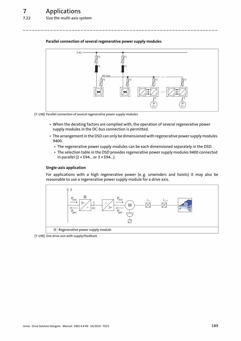
7 Applications7.22 Size the multi-axis system
_ _ _ _ _ _ _ _ _ _ _ _ _ _ _ _ _ _ _ _ _ _ _ _ _ _ _ _ _ _ _ _ _ _ _ _ _ _ _ _ _ _ _ _ _ _ _ _ _ _ _ _ _ _ _ _ _ _ _ _ _ _ _ _
Parallel connection of several regenerative power supply modules
[7-198] Parallel connection of several regenerative power supply modules
• When the derating factors are complied with, the operation of several regenerative power supply modules in the DC-bus connection is permitted.
• The arrangement in the DSD can only be dimensioned with regenerative power supply modules 9400.• The regenerative power supply modules can be each dimensioned separately in the DSD.• The selection table in the DSD provides regenerative power supply modules 9400 connected
in parallel (2 × E94... or 3 × E94...).
Single-axis application
For applications with a high regenerative power (e. g. unwinders and hoists) it may also bereasonable to use a regenerative power supply module for a drive axis.
[7-199] One drive axis with supply/feedback
Regenerative power supply module
Lenze · Drive Solution Designer · Manual · DMS 4.9 EN · 10/2019 · TD23 189

7 Applications7.22 Size the multi-axis system
_ _ _ _ _ _ _ _ _ _ _ _ _ _ _ _ _ _ _ _ _ _ _ _ _ _ _ _ _ _ _ _ _ _ _ _ _ _ _ _ _ _ _ _ _ _ _ _ _ _ _ _ _ _ _ _ _ _ _ _ _ _ _ _
Multi-axis application
[7-200] Multi-axis application with supply/feedback
7.22.2.2 Central mains supply via power supply module
[7-201] Central mains supply via power supply module
Excessive electrical energy (braking energy) is made available to the drive axes in the DC-busconnection.
• The arrangement can be dimensioned in the DSD.• The drive axes can be each dimensioned separately in the DSD.• In the "Dimension the multi-axis system" application you combine the drive axes and
dimension the power supply module.• DSD calculates the entire power requirement. For operation in generator mode it is checked
whether the braking power needs to be dissipated via an additional brake resistor.
Regenerative power supply module
190 Lenze · Drive Solution Designer · Manual · DMS 4.9 EN · 10/2019 · TD23

7 Applications7.22 Size the multi-axis system
_ _ _ _ _ _ _ _ _ _ _ _ _ _ _ _ _ _ _ _ _ _ _ _ _ _ _ _ _ _ _ _ _ _ _ _ _ _ _ _ _ _ _ _ _ _ _ _ _ _ _ _ _ _ _ _ _ _ _ _ _ _ _ _
Multi-axis application
[7-202] Multi-axis application with central supply and central brake resistor
[7-203] Multi-axes application with a central supply and i700 servo inverters as axis modules
Power supply module, e.g. power supply module 9400
Lenze · Drive Solution Designer · Manual · DMS 4.9 EN · 10/2019 · TD23 191

7 Applications7.22 Size the multi-axis system
_ _ _ _ _ _ _ _ _ _ _ _ _ _ _ _ _ _ _ _ _ _ _ _ _ _ _ _ _ _ _ _ _ _ _ _ _ _ _ _ _ _ _ _ _ _ _ _ _ _ _ _ _ _ _ _ _ _ _ _ _ _ _ _
7.22.2.3 Central mains supply via inverter
[7-204] Central mains supply via inverter
• The arrangement cannot be dimensioned in the DSD.• The drive axes can be each dimensioned separately in the DSD.• The DC parameters for the inverter on the mains must be calculated manually. The required
intermediate results are provided by DSD.• The entire power balance must be calculated manually.
• In general, it is possible to actuate i700 servo inverters as axis modules via the DC bus of an inverter.• The drive axes can be each dimensioned separately in the DSD.• The DC parameters for the inverter on the mains must be calculated manually. The required
intermediate results are provided by DSD.
7.22.2.4 Decentralised mains supply via several inverters
[7-205] Decentralised mains supply via several inverters
• The arrangement cannot be dimensioned in the DSD.• The drive axes can be each dimensioned separately in the DSD.• Additional parameters for the DC bus connection must be determined manually.
192 Lenze · Drive Solution Designer · Manual · DMS 4.9 EN · 10/2019 · TD23

7 Applications7.22 Size the multi-axis system
_ _ _ _ _ _ _ _ _ _ _ _ _ _ _ _ _ _ _ _ _ _ _ _ _ _ _ _ _ _ _ _ _ _ _ _ _ _ _ _ _ _ _ _ _ _ _ _ _ _ _ _ _ _ _ _ _ _ _ _ _ _ _ _
7.22.2.5 Decentralised mains supply via regenerative power supply modules and inverters
[7-206] Decentralised mains supply via regenerative power supply modules and inverters
• The regenerative power supply module increases the power of the drive in motor mode (reasonable for e.g. hoist drives).• The regenerative power is not increased.
• The arrangement cannot be dimensioned in the DSD.• The regenerative power supply module and the drive axis can be each dimensioned
separately in the DSD.• The parallel connection must be calculated manually. The required intermediate results are
provided by DSD.• The entire power balance must be calculated manually.
Lenze · Drive Solution Designer · Manual · DMS 4.9 EN · 10/2019 · TD23 193

7 Applications7.22 Size the multi-axis system
_ _ _ _ _ _ _ _ _ _ _ _ _ _ _ _ _ _ _ _ _ _ _ _ _ _ _ _ _ _ _ _ _ _ _ _ _ _ _ _ _ _ _ _ _ _ _ _ _ _ _ _ _ _ _ _ _ _ _ _ _ _ _ _
7.22.3 Combining Lenze products
Overview of combinability of inverters and additional components with power supply modules orregenerative power supply modules.
Equations for the calculation of the effective moment of inertia for linear motors
Axis A Axis B Symbol Description Dimension unit
- - s Length which is the basis of the number of encoder increments.(e.g. pole spacing or total length)
m
- - 2pole pair Pole spacing of the permanent magnets, pole pair width m
- - J Mass moment of inertia kg m2
- - m Mass of carriage kg
Power supply module Regenerative power supply module
E94APNIDC = 10 ... 245 A
PDC = 5.6 ... 137 kW
E70ACPSxIN,DC = 30/60 A
E94xxPDC,mot = 15/30 kWPDC,gen = 7.5/15 kW
Servo inverter
Servo Drives 9400 HighLine (Single Drives)
0.37 … 11 kW
15 … 30 kW
45 … 55 kW
75 … 370 kW
Servo Drives 9400 HighLine (Multi Drives)
Inverter Drives 8400 TopLine
i700 servo inverter
Frequency inverter
Inverter Drives 8400 StateLine
Inverter Drives 8400 HighLine
Additional component
Brake resistor ERBx
The combination is possible without restrictions.
The combination is possible with restrictions:
The EMC protection of the device is not effective in the DC-bus connection. Check whether EMC measures are required for the entire DC-bus connection or machine.
The braking circuit of the drive axis cannot be dimensioned in the DSD. DSD only dimensions a central braking circuit as it is for example contained in the 9400 power supply module.If alternative or additional brake choppers are to be set in the drive axes, these braking circuits have to be checked manually.
No or no sufficient starting current limitation available. Special measures have to be taken. Please contact your Lenze sales partner.
The combination is not reasonable since the power range of the power supply module or the regenerative power supply module is too low. If the DSD does not display an active message when the module is selected, you can use this combination.
zp Integers
2Pole pair------------------------ = J m
zp 2Pole pair
2-----------------------------------
2=
194 Lenze · Drive Solution Designer · Manual · DMS 4.9 EN · 10/2019 · TD23

7 Applications7.22 Size the multi-axis system
_ _ _ _ _ _ _ _ _ _ _ _ _ _ _ _ _ _ _ _ _ _ _ _ _ _ _ _ _ _ _ _ _ _ _ _ _ _ _ _ _ _ _ _ _ _ _ _ _ _ _ _ _ _ _ _ _ _ _ _ _ _ _ _
7.22.4 Dimensioning
[7-207] General procedure of dimensioning a coordinated multi-axis system
Description
Go to the independent MotionDesigner, create the motion profiles for all drive axes and save them to a file (*lmp).
• Movement of drive axes ( 198)
Dimension all drive axes of the multi-axis system.• Load the Imp file with the motion profiles in the MotionDesigner of the drive axis, select and accept the
corresponding motion profile.• Select "Inverter with DC supply (multi-axis application)" as electrical drive concept. DSD automatically
reduces the selection and only offers inverters that are suitable for the DC-bus connection.• Dimension components and consider the compatibility of the products in the DC bus.
• Combining Lenze products ( 194) • The power in generator and motor mode in the DC bus is calculated separately. DSD considers
influencing values as power required of the application, power loss of the drive components and kinetic energy demand due to mass inertia.
Select the "Dimension multi-axis system" application and read in the DSD projects of the drive axes.• Optional processing for each DSD project:
• Time displacement of the motion profile.• Multiple repetition of the motion profile.• Number of drive axes for a DSD project.
• Dimension components and define possible supply strategies:• Central mains supply via regenerative power supply module ( 188) • Central mains supply via power supply module ( 190)
Lenze · Drive Solution Designer · Manual · DMS 4.9 EN · 10/2019 · TD23 195

7 Applications7.22 Size the multi-axis system
_ _ _ _ _ _ _ _ _ _ _ _ _ _ _ _ _ _ _ _ _ _ _ _ _ _ _ _ _ _ _ _ _ _ _ _ _ _ _ _ _ _ _ _ _ _ _ _ _ _ _ _ _ _ _ _ _ _ _ _ _ _ _ _
7.22.5 Parameterising projects
Legend Description
Drive axis (*.dsd)• Added DSD projects.• The file name is displayed.
Add project button• Adds a DSD project to the multi-axis application.• In order to add several DSD projects at the same time, select several files in the Add project dialog
box:• In order to select single files, keep <Ctrl> pressed and left-click the respective files.• In order to select an area, keep <Shift> pressed and left-click the first and the last file.
Delete project button• Deletes a highlighted DSD project from the multi-axis application.
Update project button• Updates the parameters if an added DSD project was changed. The DSD projects of the individual
drive axes are linked to the multi-axis application.• Recommendation: Save the DSD project of the multi-axis application and the DSD projects of the
single drive axes to the same directory.• The linking remains active if the entire directory is shifted and the multi-axis application is
opened.• The linking gets lost if a project file is shifted.
196 Lenze · Drive Solution Designer · Manual · DMS 4.9 EN · 10/2019 · TD23

7 Applications7.22 Size the multi-axis system
_ _ _ _ _ _ _ _ _ _ _ _ _ _ _ _ _ _ _ _ _ _ _ _ _ _ _ _ _ _ _ _ _ _ _ _ _ _ _ _ _ _ _ _ _ _ _ _ _ _ _ _ _ _ _ _ _ _ _ _ _ _ _ _
[7-208] Motion profiles: Relationship of starting time t0, number of repetitions NT and cycle time tCrd
Parameter Unit Description
Metric Imperial
U V V Mains voltage of the AC supply system. The DC-bus voltage is expected to be generated by rectifying the mains voltage.
• Read only.• You can only add DSD projects that have been
dimensioned with the same mains voltage.
Drive axis (*.dsd) Names of the inserted DSD projects.• Read only.• An added DSD project makes at least one drive axis.
ND Number of drive axes that are assigned to the DSD project.
t0 s s Postpone the starting time of the motion profile.
NT Number of how often the motion profile is repeated.
t s s Time in which the motion profile is running.• Read only.
Pmot,max kW kW Max. required power to be provided by the supply component.
• Read only.
Pgen,max kW kW Max. regenerative power which may occur in the DC bus.• If multiple regenerative power supply modules are
connected in parallel, the occurring peak braking power is distributed to the individual modules.
• Read only.
Prated kW kW Rated power of the inverter.• Corresponds to the typical motor power of a standard
asynchronous four-pole motor.
P(inverter kW kW
Total Sum of the values per column.Read only.
Weighted total Average consisting of the sum of the values and the number of axes.
• Read only.
tCrd
t0
NT = 1
NT = 2
t
t
Lenze · Drive Solution Designer · Manual · DMS 4.9 EN · 10/2019 · TD23 197

7 Applications7.22 Size the multi-axis system
_ _ _ _ _ _ _ _ _ _ _ _ _ _ _ _ _ _ _ _ _ _ _ _ _ _ _ _ _ _ _ _ _ _ _ _ _ _ _ _ _ _ _ _ _ _ _ _ _ _ _ _ _ _ _ _ _ _ _ _ _ _ _ _
7.22.6 Defining options
7.22.6.1 Movement of drive axes
For dimensioning the power supply module or regenerative power supply module and the brakingcircuit, the selection "coordinated axes" or "uncoordinated axes" is decisive.
• The DC-bus power of coordinated and uncoordinated motion sequences is calculated differently.
Coordinated multi-axis system
In a coordinated multi-axis system, the motion sequences are in a permanently time-definedrelationship (e.g. applications with cams or clock-related systems).
• In the DSD, you can optimally dimension a multi-axis system with coordinated drive axes relating to energy.• Lenze BlueGreen Solutions serves to calculate amortisation times quickly. The cost-cutting
potentials are documented in an Energy Performance Certificate.Energy efficiency ( 414)
[7-209] Power characteristic of two coordinated drive axes
Parameter Description
Motion of axes • Axes coordinated• There are definitions governing the movements of the individual axes in relation to one
another which are fixed in time.• Axes uncoordinated
• The movements of the individual axes are not defined and are not coordinated to each other.
Power characteristic drive axis 1
Power characteristic drive axis 2
Total power
198 Lenze · Drive Solution Designer · Manual · DMS 4.9 EN · 10/2019 · TD23

7 Applications7.22 Size the multi-axis system
_ _ _ _ _ _ _ _ _ _ _ _ _ _ _ _ _ _ _ _ _ _ _ _ _ _ _ _ _ _ _ _ _ _ _ _ _ _ _ _ _ _ _ _ _ _ _ _ _ _ _ _ _ _ _ _ _ _ _ _ _ _ _ _
Uncoordinated multi-axis system
Uncoordinated motion sequences are not associated with regard to time. Even if only single driveaxes of the multi-axis system are uncoordinated, the DSD calculates with the most unfavourablepower characteristic:
• The peak powers of all single axes occur at the same time.
• The supply components of the network must provide the sum of peak powers in generator mode and in motor mode of all drive axes.
[7-210] Power characteristic for two uncoordinated drive axes
7.22.6.2 Cycle time for coordinated multi-axis grouping
Power characteristic drive axis 1
Power characteristic drive axis 2
The determination of the total power is not possible because there is no relationship between the power characteristics.
Parameter Description
tCrd Cycle time for coordinated multi-axis grouping.For drive axes with motion profiles with different time lengths, the DSD calculates with the longest motion profile. For the shorter motion profiles, the DSD considers until the end of the entire cycle the performance values that are provided at the end of each motion profile defined with regard to time.The min. adjustable cycle time results from the product t × NT.
• t: Cycle time of the longest motion profile• NT: Number of how often the motion profile is repeated.• It is not possible to fall below the cycle times of the motion profiles of the individual drive
axes.• Parameter is only available in case of a coordinated multi-axis system.Parameterising projects ( 196)
Lenze · Drive Solution Designer · Manual · DMS 4.9 EN · 10/2019 · TD23 199

7 Applications7.23 Winding drive for rewinder/unwinder
_ _ _ _ _ _ _ _ _ _ _ _ _ _ _ _ _ _ _ _ _ _ _ _ _ _ _ _ _ _ _ _ _ _ _ _ _ _ _ _ _ _ _ _ _ _ _ _ _ _ _ _ _ _ _ _ _ _ _ _ _ _ _ _
7.23 Winding drive for rewinder/unwinder
7.23.1 Rewinder (single)
Rewinders are used in many production processes. They are able to store continuous material afterthe machining process.
The roller of a single rewinder can only be changed at standstill. The winding drive is braked tostandstill and then accelerated to production speed again after changing the roller. A webaccumulator serves to change the roller without the need for a production downtime. When thewinding drive is at standstill, the web accumulator stores the produced material.
Materials to be processed are e.g.: homogeneous webs (e.g. paper webs), fabrics, meshwork, wires,threads or fibres. From a mathematical point of view, the wound up material is a spiral. Dependingon the application range and industry sector, the spiral is called reel, spool, coil or tree.
There are two winding technologies:
• Lay-up winding (e.g. foils, paper, plates).
• Filament winding (e.g. threads, fibres, wires, cables). This winding technology is not supported by DSD.
The requirements for the winding drive depend on the winding material and may be very high:
• No impacts on the winding material during the winding process.
• High speed and torque setting ranges.
• Dynamic phase must not have any negative impacts on the tensile force.
200 Lenze · Drive Solution Designer · Manual · DMS 4.9 EN · 10/2019 · TD23

7 Applications7.23 Winding drive for rewinder/unwinder
_ _ _ _ _ _ _ _ _ _ _ _ _ _ _ _ _ _ _ _ _ _ _ _ _ _ _ _ _ _ _ _ _ _ _ _ _ _ _ _ _ _ _ _ _ _ _ _ _ _ _ _ _ _ _ _ _ _ _ _ _ _ _ _
7.23.1.1 Calculations
Translatory acceleration
[7-211] Equation 1: Translatory acceleration
Sizing diameter
[7-212] Equation 2: Dimensioning diameter for the reel
Max. winding ratio
[7-213] Equation 3: Max. winding ratio
Dimensioning winding ratio
The DSD limits the qdim dimensioning winding ratio to 200.
[7-214] Equation 4: Dimensioning winding ratio
Winding characteristic
[7-215] Equation 5: Winding characteristic
Diameter characteristic
[7-216] Equation 6: Diameter characteristic of the reel
Mass of the winding material
[7-217] Equation 7: Mass of the winding material
advdt------ v
t-------==
ddim
2 vmax tacc sMin
-------------------------------------------------- dMin
2+=
qmax
dmax
dMin------------=
qdim
dmax
ddim------------=
HW
Fmax dmax
Fmax dMin ------------------------------ q 1–
q 1–------------------------------------------------=
d2--- v0 v1+ t1 t0– s di
2+ =
mL 4--- di
2dMin
2 bmax– =
Lenze · Drive Solution Designer · Manual · DMS 4.9 EN · 10/2019 · TD23 201
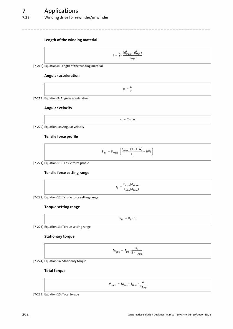
7 Applications7.23 Winding drive for rewinder/unwinder
_ _ _ _ _ _ _ _ _ _ _ _ _ _ _ _ _ _ _ _ _ _ _ _ _ _ _ _ _ _ _ _ _ _ _ _ _ _ _ _ _ _ _ _ _ _ _ _ _ _ _ _ _ _ _ _ _ _ _ _ _ _ _ _
Length of the winding material
[7-218] Equation 8: Length of the winding material
Angular acceleration
[7-219] Equation 9: Angular acceleration
Angular velocity
[7-220] Equation 10: Angular velocity
Tensile force profile
[7-221] Equation 11: Tensile force profile
Tensile force setting range
[7-222] Equation 12: Tensile force setting range
Torque setting range
[7-223] Equation 13: Torque setting range
Stationary torque
[7-224] Equation 14: Stationary torque
Total torque
[7-225] Equation 15: Total torque
l4---
dmax2
dMin2
–
sMin------------------------------------=
ar---=
2 n=
Fpll Fmax
dMin 1 HW)–
di---------------------------------------- HW+
=
kF
Fmax dmax
FMin dMin ------------------------------=
kM KF q=
Msds Fpll
di
2 App--------------------=
Msum Msds JWnd
App-------------+=
202 Lenze · Drive Solution Designer · Manual · DMS 4.9 EN · 10/2019 · TD23

7 Applications7.23 Winding drive for rewinder/unwinder
_ _ _ _ _ _ _ _ _ _ _ _ _ _ _ _ _ _ _ _ _ _ _ _ _ _ _ _ _ _ _ _ _ _ _ _ _ _ _ _ _ _ _ _ _ _ _ _ _ _ _ _ _ _ _ _ _ _ _ _ _ _ _ _
Required process power
[7-226] Equation 16: Required power of the application
Field weakening factor
[7-227] Equation 17: Field weakening factor of the motor
Required motor output
[7-228] Equation 18: Required motor power
PApp Fmax
vmax
------------=
kf
nmax
nN-------------=
PM
Fmax dmax vmax dmax
kf ddim
-----------------------------------------------------------------=
Lenze · Drive Solution Designer · Manual · DMS 4.9 EN · 10/2019 · TD23 203

7 Applications7.23 Winding drive for rewinder/unwinder
_ _ _ _ _ _ _ _ _ _ _ _ _ _ _ _ _ _ _ _ _ _ _ _ _ _ _ _ _ _ _ _ _ _ _ _ _ _ _ _ _ _ _ _ _ _ _ _ _ _ _ _ _ _ _ _ _ _ _ _ _ _ _ _
7.23.1.2 Symbols used
Symbol Description Dimension unit
a Translatory acceleration m/s2
bmax Max. width of the winding material mm
d Diameter characteristic mm
ddim Sizing diameter• Diameter which is reached after termination of the acceleration phase.
mm
dmin Minimum reel diameter (initial diameter) mm
dmax Maximum reel diameter mm
Fmin(dmin) Min. tensile force with min. reel diameter (initial diameter) N
Fmax(dmin) Max. tensile force with min. reel diameter N
Fmax(dmax) Max. tensile force with max. reel diameter N
HW Winding characteristic (hard/soft)• describes the tensile force drop as a function of the reel diameter
kf Field weakening factor
kf Tensile force setting range
kM Torque setting range
l Length of the winding material m
Msds Stationary torque Nm
msum Total torque Nm
nmax Max. motor speed rpm
nrated Rated speed of the motor rpm
Average density of winding material kg/dm3
PApp Required process power
PM Required motor output kW
q Winding ratio
qmax Maximum winding ratio
qdim Dimensioning winding ratio• The DSD limits qdim to 200.
smin Thickness of the winding material• If multiple materials are wound, the smallest material thickness must be
indicated.
mm
tacc Acceleration time of the winding drive m/s
tdec Deceleration time of the winding drive m/s
vmax Max. material speed m/min
Angular acceleration rad/s2
Mechanical efficiency of the winding system (coil and coil intake)
Angular velocity rad/s
204 Lenze · Drive Solution Designer · Manual · DMS 4.9 EN · 10/2019 · TD23

7 Applications7.23 Winding drive for rewinder/unwinder
_ _ _ _ _ _ _ _ _ _ _ _ _ _ _ _ _ _ _ _ _ _ _ _ _ _ _ _ _ _ _ _ _ _ _ _ _ _ _ _ _ _ _ _ _ _ _ _ _ _ _ _ _ _ _ _ _ _ _ _ _ _ _ _
7.23.2 Unwinder (single)
Unwinders are used in many production processes. They store continuous material and feed it to aproduction process which can be carried out in a continuous or discontinuous manner.
The roller of a single rewinder can only be changed at standstill. The winding drive is braked tostandstill and then accelerated to production speed again after changing the roller. A webaccumulator serves to change the roller without the need for a production downtime. When thewinding drive is at standstill, the web accumulator feeds the winding material to the productionprocess.
Materials to be processed are e.g.: homogeneous webs (e.g. paper webs), fabrics, meshwork, wires,threads or fibres. From a mathematical point of view, the wound up material is a spiral. Dependingon the application range and industry sector, the spiral is called reel, spool, coil or tree.
There are two winding technologies:
• Lay-up winding (e.g. foils, paper, plates).
• Filament winding (e.g. threads, fibres, wires, cables). This winding technology is not supported by DSD.
The requirements for the winding drive depend on the winding material and may be very high:
• High speed and torque setting ranges.
• Dynamic phase must not have any negative impacts on the tensile force.
Lenze · Drive Solution Designer · Manual · DMS 4.9 EN · 10/2019 · TD23 205

7 Applications7.23 Winding drive for rewinder/unwinder
_ _ _ _ _ _ _ _ _ _ _ _ _ _ _ _ _ _ _ _ _ _ _ _ _ _ _ _ _ _ _ _ _ _ _ _ _ _ _ _ _ _ _ _ _ _ _ _ _ _ _ _ _ _ _ _ _ _ _ _ _ _ _ _
7.23.2.1 Calculations
Translatory acceleration
[7-229] Equation 1: Translatory acceleration
Sizing diameter
[7-230] Equation 2: Dimensioning diameter for the reel
Max. winding ratio
[7-231] Equation 3: Max. winding ratio
Dimensioning winding ratio
The DSD limits the qdim dimensioning winding ratio to 200.
[7-232] Equation 4: Dimensioning winding ratio
Diameter characteristic
[7-233] Equation 5: Diameter characteristic of the reel
Mass of the winding material
[7-234] Equation 6: Mass of the winding material
Length of the winding material
[7-235] Equation 7: Length of the winding material
advdt------ v
t-------==
ddim
2 vmax tacc sMin
------------------------------------------------- dMin
2+=
qmax
dmax
dMin------------=
qdim
dmax
ddim------------=
d2--- v0 v1+ t1 t0– sMin di
2+ =
mL 4--- di
2dMin
2 bmax– =
l4---
dmax2
dMin2
–
s------------------------------------=
206 Lenze · Drive Solution Designer · Manual · DMS 4.9 EN · 10/2019 · TD23

7 Applications7.23 Winding drive for rewinder/unwinder
_ _ _ _ _ _ _ _ _ _ _ _ _ _ _ _ _ _ _ _ _ _ _ _ _ _ _ _ _ _ _ _ _ _ _ _ _ _ _ _ _ _ _ _ _ _ _ _ _ _ _ _ _ _ _ _ _ _ _ _ _ _ _ _
Angular acceleration
[7-236] Equation 8: Angular acceleration
Angular velocity
[7-237] Equation 9: Angular velocity
Tensile force setting range
[7-238] Equation 10: Tensile force setting range
Torque setting range
[7-239] Equation 11: Torque setting range
Speed setting range
[7-240] Equation 12: Speed setting range
Speed setting range
[7-241] Equation 13: Velocity setting range
Stationary torque
[7-242] Equation 15: Stationary torque
Total torque
[7-243] Equation 16: Total torque
ar---=
2 n=
kF
Fmax
FMin------------=
kM KF q=
kn
nmax
nMin-------------=
kv
vmax
vMin------------=
Msds Fpll
di
2---- App =
Msum Msds JWndd
App-------------+=
Lenze · Drive Solution Designer · Manual · DMS 4.9 EN · 10/2019 · TD23 207

7 Applications7.23 Winding drive for rewinder/unwinder
_ _ _ _ _ _ _ _ _ _ _ _ _ _ _ _ _ _ _ _ _ _ _ _ _ _ _ _ _ _ _ _ _ _ _ _ _ _ _ _ _ _ _ _ _ _ _ _ _ _ _ _ _ _ _ _ _ _ _ _ _ _ _ _
Required process power
[7-244] Equation 17: Required power of the application
Field weakening factor
[7-245] Equation 18: Field weakening factor of the motor
Required motor output
[7-246] Equation 19: Required motor power
PApp Fmax vmax =
kf
nmax
nN-------------=
PM
Fmax vmax dmax
kf ddim------------------------------------------------------=
208 Lenze · Drive Solution Designer · Manual · DMS 4.9 EN · 10/2019 · TD23

7 Applications7.23 Winding drive for rewinder/unwinder
_ _ _ _ _ _ _ _ _ _ _ _ _ _ _ _ _ _ _ _ _ _ _ _ _ _ _ _ _ _ _ _ _ _ _ _ _ _ _ _ _ _ _ _ _ _ _ _ _ _ _ _ _ _ _ _ _ _ _ _ _ _ _ _
7.23.2.2 Symbols used
Symbol Description Dimension unit
a Translatory acceleration m/s2
bmax Max. width of the winding material mm
d Diameter characteristic mm
ddim Sizing diameter• Diameter which is reached after termination of the acceleration phase.
mm
dmin Minimum reel diameter (initial diameter) mm
dmax Maximum reel diameter mm
Fmin Tensile force with min. reel diameter N
Fmax Tensile force with max. reel diameter (initial diameter) N
kf Field weakening factor
kf Tensile force setting range
kM Torque setting range
kn Speed setting range
kv Speed setting range
l Length of the winding material m
Msds Stationary torque Nm
msum Total torque Nm
nmax Max. motor speed rpm
nrated Rated speed of the motor rpm
Average density of winding material kg/dm3
PApp Required process power
PM Required motor output kW
q Winding ratio
qmax Maximum winding ratio
qdim Dimensioning winding ratio• The DSD limits qdim to 200.
smin Thickness of the winding material• If multiple materials are wound at the same time, the smallest material
thickness must be indicated.
mm
tacc Acceleration time of the winding drive m/s
tdec Deceleration time of the winding drive m/s
vmax Max. speed of the material m/min
Angular acceleration rad/s2
Mechanical efficiency of the winding system (coil and coil intake)
Angular velocity rad/s
Lenze · Drive Solution Designer · Manual · DMS 4.9 EN · 10/2019 · TD23 209

7 Applications7.23 Winding drive for rewinder/unwinder
_ _ _ _ _ _ _ _ _ _ _ _ _ _ _ _ _ _ _ _ _ _ _ _ _ _ _ _ _ _ _ _ _ _ _ _ _ _ _ _ _ _ _ _ _ _ _ _ _ _ _ _ _ _ _ _ _ _ _ _ _ _ _ _
7.23.3 Dimensioning strategies
The diagram below shows the basic procedure for dimensioning a winding drive. DSD automaticallyguides you through the required dimensioning steps.
[7-247] Strategy for dimensioning a winding drive in DSD
210 Lenze · Drive Solution Designer · Manual · DMS 4.9 EN · 10/2019 · TD23

7 Applications7.23 Winding drive for rewinder/unwinder
_ _ _ _ _ _ _ _ _ _ _ _ _ _ _ _ _ _ _ _ _ _ _ _ _ _ _ _ _ _ _ _ _ _ _ _ _ _ _ _ _ _ _ _ _ _ _ _ _ _ _ _ _ _ _ _ _ _ _ _ _ _ _ _
The following functions are efficient tools for comparing drive solutions and representing differentscenarios.
Generate alternative
For an optimal drive dimensioning, it is wise to create different motor technologies, field weakeningfactors, mechanical ratios and inverters as separate projects and to compare them.
The Creating an alternative function serves to create a copy - from the current project up to thedesired dimensioning step. Every project can be dimensioned with different parameters. ( 55)
Project comparison
The Project comparison function serves to compare all important parameters relevant to thedimensioning in the opened DSD projects (alternative dimensionings). Other comparison criteriasuch as price, construction volume and mass must be compared manually. This information helpsselect an optimal drive solution together with the customer. ( 59)
Application Tuner
Based on a found drive solution (reference), the Application Tuner function serves to check theoperation under different conditions (e.g. emergency switching off scenarios) or with differentparameters (e.g. different recipes, other materials, alternative motion profile) and to draw acomparison with the reference. ( 57)
The drive solution found via Application Tuner can be logged in DSD and saved as separate project.
Lenze · Drive Solution Designer · Manual · DMS 4.9 EN · 10/2019 · TD23 211

7 Applications7.23 Winding drive for rewinder/unwinder
_ _ _ _ _ _ _ _ _ _ _ _ _ _ _ _ _ _ _ _ _ _ _ _ _ _ _ _ _ _ _ _ _ _ _ _ _ _ _ _ _ _ _ _ _ _ _ _ _ _ _ _ _ _ _ _ _ _ _ _ _ _ _ _
7.23.4 Traction-controlled winding drive
In winding drives, the tensile force is generated by the static torque Mstat. During the accelerationand deceleration phases, the drive requires an additional dynamic torque Mdyn.
In order to prevent the tensile force from exceeding the limit values and in order to avoid emptyreels, the dynamic component of the torque should be smaller than the static component fortraction-controlled winders. If the disturbance compensation works well and is repeatable, thedynamic component may be a little greater than the static component. Critical phases areaccelerations during the start of winding to an empty reel with minimum tensile force.
• Guide value: Mdyn < 1 ... 3 × Mstat
Tip!
How to limit the dynamic torque:• Select moderate acceleration and deceleration times• Create an S-shaped motion profile
The Mdyn/Mstat ratio can be read from the torque-time characteristic of the motor. Dimension thedrive completely and zoom in on the start of the characteristic (starting time) to be able to see thedynamic torque. Use the Zoom function for this purpose. Diagrams for the components ( 431)
[7-248] Torque-time characteristic of the motor
212 Lenze · Drive Solution Designer · Manual · DMS 4.9 EN · 10/2019 · TD23

7 Applications7.23 Winding drive for rewinder/unwinder
_ _ _ _ _ _ _ _ _ _ _ _ _ _ _ _ _ _ _ _ _ _ _ _ _ _ _ _ _ _ _ _ _ _ _ _ _ _ _ _ _ _ _ _ _ _ _ _ _ _ _ _ _ _ _ _ _ _ _ _ _ _ _ _
7.23.5 Checking emergency-off scenarios
DSD is only partially able to check emergency-off scenarios. The user interface and the DSD protocoldisplay a note.
[7-249] Motor diagram: winder torque (diameter-related)
The Application Tuner may help with the required additional checks. Application Tuner ( 57)
Note!
The torque required for emergency stop is greater than the drive torque available.• The torque required for emergency stop is calculated and represented in the
diameter-dependent torque diagram of the motor. The calculation is based on the emergency stop time, a linear motion profile, and a tensile force = 0 N (material crack).
• The thermal utilisation of the drive components is not checked.• Braking circuits are not dimensioned.
Description
Torque required for emergency stop
Max. available drive torque
Lenze · Drive Solution Designer · Manual · DMS 4.9 EN · 10/2019 · TD23 213
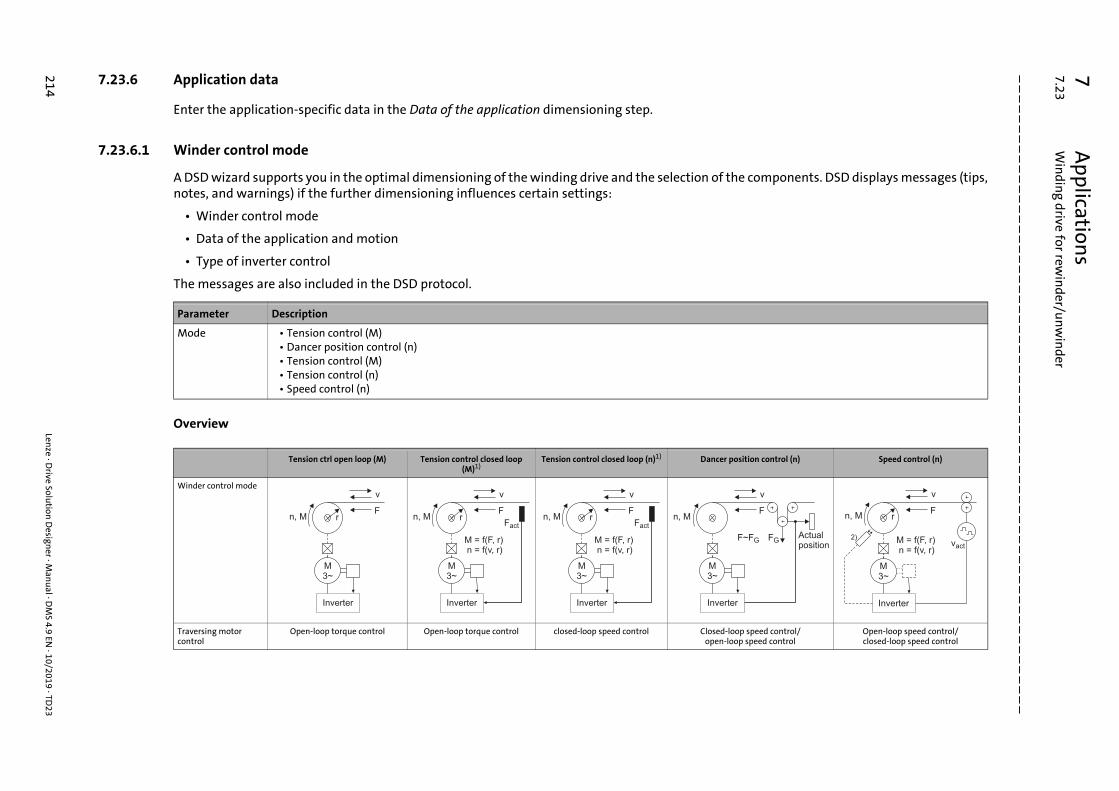
7A
pplications
7.23W
indin
g drive for rewin
der/un
win
der
214Len
ze · Drive Solu
tion D
esigner · M
anu
al · DM
S 4.9 EN · 10/2019 · TD
23
_ _ _ _ _ _ _ _ _ _ _ _ _ _ _ _ _ _ _ _ _ _ _ _ _ _ _ _ _ _ _ _ _ _ _ _ _ _ _ _ _ _ _ _ _ _ _ _ _ _ _ _ _ _ _ _ _ _ _ _ _ _ _ _
7.23.6 Application data
Enter the application-specific data in the Data of the application dimensioning step.
he components. DSD displays messages (tips,
osition control (n) Speed control (n)
oop speed control/oop speed control
Open-loop speed control/closed-loop speed control
v
F
F~FG FGActualposition
er
v
F
M3~
n, M r
vact
Inverter
M = f(F, r)n = f(v, r)
2)
7.23.6.1 Winder control mode
A DSD wizard supports you in the optimal dimensioning of the winding drive and the selection of tnotes, and warnings) if the further dimensioning influences certain settings:
• Winder control mode
• Data of the application and motion
• Type of inverter control
The messages are also included in the DSD protocol.
Overview
Parameter Description
Mode • Tension control (M)• Dancer position control (n)• Tension control (M)• Tension control (n)• Speed control (n)
Tension ctrl open loop (M) Tension control closed loop (M)1)
Tension control closed loop (n)1) Dancer p
Winder control mode
Traversing motor control
Open-loop torque control Open-loop torque control closed-loop speed control Closed-lopen-l
v
Fn, M r
M3~
Inverter
v
Fn, M r
M = f(F, r)n = f(v, r)
Fact
M3~
Inverter
v
Fn, M r
M = f(F, r)n = f(v, r)
Fact
M3~
Inverter
n, M
M3~
Invert

7A
pplications
7.23W
indin
g drive for rewin
der/un
win
der
Lenze · D
rive Solution
Design
er · Man
ual · D
MS 4.9 EN
· 10/2019 · TD23
215
_ _ _ _ _ _ _ _ _ _ _ _ _ _ _ _ _ _ _ _ _ _ _ _ _ _ _ _ _ _ _ _ _ _ _ _ _ _ _ _ _ _ _ _ _ _ _ _ _ _ _ _ _ _ _ _ _ _ _ _ _ _ _ _ Description Indirect tension control via the Torque-controlled process with Speed-controlled process with a Tension control open loop via dancers. The
d in a speed- and position-hion. Further tasks of the ion of the actual position. or for the compensation of f the winding reel (e.g. in the unwinder) and of continuities.
The tensile force is determined by the upstream system. The winder works as master in the drive system and conveys
the material with a constant circumferential speed. The
circumferential speed is treated with closed-loop control, the speed is treated
with closed- or open-loop control.
ost-effective winding low to high requirements tensile force quality and profile. Well suited for els, e.g. in the case of
unwinders.
Unwinders for slitting lines.
++ 3)/++ 3) ++ 3)/++ 3)
O/O O/O
O/– O/–
O/O O/O
–/– –/–
ptimised field injection in the partial load operational range
Tension ctrl open loop (M) Tension control closed loop (M)1)
Tension control closed loop (n)1) Dancer position control (n) Speed control (n)
drive torque with disturbance compensation (friction,
acceleration).
a higher-level tension control closed loop and interference
compensation (friction, acceleration). The actual tensile force value is recorded by means of a sensor at the material web.
higher-level tension control closed loop and interference
compensation (friction, acceleration). The actual tensile force value is recorded by means of a sensor at the material web.
drive is actuatecontrolled fas
dancer: detectWeb accumulat
eccentricities othe case of
dis
Application area Universal, cost-effective winding procedure for low to high
requirements with regard to tensile force quality and tensile force
profile.
Winding procedure for high requirements with regard to
tensile force quality and tensile force profile.
Winding procedure for high requirements with regard to
tensile force quality and tensile force profile.
Universal, cprocedure for with regard to
tensile forceeccentric re
Control system
SC
Rewinder/unwinder ++/++ ++/++ ++/++
VFC plus without encoder
Rewinder/unwinder –/– –/– –/–
SLVC
Rewinder/unwinder 0/– –/– –/–
VFC plus with encoder
Rewinder/unwinder O/– –/– –/–
VFC plus eco
Rewinder/unwinder –/– –/– –/–
++ Well-suited SC Servo control
O Suitable with restrictions VFC plus V/f control
– Not suitable VFC plus eco V/f control with energetically o
1) Comparison of tension-controlled winder control modes ( 216) SLVC Sensorless vector control
2) Diameter measurement, e.g. with an ultrasonic sensor (optional)
3) Motorgeber erforderlich

7 Applications7.23 Winding drive for rewinder/unwinder
_ _ _ _ _ _ _ _ _ _ _ _ _ _ _ _ _ _ _ _ _ _ _ _ _ _ _ _ _ _ _ _ _ _ _ _ _ _ _ _ _ _ _ _ _ _ _ _ _ _ _ _ _ _ _ _ _ _ _ _ _ _ _ _
Comparison of tension-controlled winder control modes
Requirement Tension control (M) Tension control (n) Note
Winder control mode
Description Torque-controlled mode with compensation for the
interference caused by friction and acceleration
Speed-controlled mode (optionally with compensation for friction and acceleration to
the torque setpoint)
Both control modes are suitable for demanding winding applications with a high
consistency in tensile force and large setting ranges
Tensile force / torque setting range max. 100 no upper limit
Acceleration behaviour +++ +++ Both modes feature acceleration compensation
Behaviour in the case of tensile force sensor failure
+++(operation possible in case of an
emergency)
–(operation not possible)
Combined winder control modes:Closed-loop controlled for lower and open-loop controlled for upper tensile force setting ranges
+++ – Application in case of a large range of materials with a large
tensile force setting range
Control mode as a function of material elasticity
suitable for no or low material elasticity (e.g. metal strips, foils,
plates, glass non-woven)
suitable for medium material elasticity, e.g. paper, films, coated
composite material
Tensile force sensor is a pathless detection system
Influence of the friction on the tensile force / torque setting range
+(great influence)
+++(little to no influence)
Suitable for unwinders with eccentric reels ++(non-sensitive behaviour)
O(sensitive behaviour)
If stored for a longer period of time, reels may deform
eccentrically
System management in case of material crack
++ +++
Control engineering requirements Medium High Adaptations to a variable moment of inertia, variable
speed
Required encoder resolution Medium High
Accuracy for the detection of the line speed Medium High Reasons for the differences between the actual and the
detected speed: coated squeegees, slip between material
and roll, tolerances in material thickness
+++ Very well suited O Suitable with restrictions
++ Well-suited – Not suitable
+ Suited
v
Fn, M r
M = f(F, r)n = f(v, r)
Fact
M3~
Inverter
v
Fn, M r
M = f(F, r)n = f(v, r)
Fact
M3~
Inverter
216 Lenze · Drive Solution Designer · Manual · DMS 4.9 EN · 10/2019 · TD23

7 Applications7.23 Winding drive for rewinder/unwinder
_ _ _ _ _ _ _ _ _ _ _ _ _ _ _ _ _ _ _ _ _ _ _ _ _ _ _ _ _ _ _ _ _ _ _ _ _ _ _ _ _ _ _ _ _ _ _ _ _ _ _ _ _ _ _ _ _ _ _ _ _ _ _ _
7.23.6.2 Min. reel diameter (rewinder)
Sizing diameter
The dimensioning diameter is the diameter which results at the end of the acceleration phase. DSDcalculates this value automatically and considers it in the drive dimensioning.
[7-250] Increase in the reel diameter during the acceleration phase without reduction of the winding speed
Parameter Description
dmin Smallest reel diameter at the beginning of the winding process (initial diameter)
dmin Min. reel diameter (initial diameter)
ddim Sizing diameter
nmax Max. winding drive speed
vmax Max. line speed
tr Acceleration time
v
vmax
n
nmax
d
ddim
dmin
tr t
t
t
Lenze · Drive Solution Designer · Manual · DMS 4.9 EN · 10/2019 · TD23 217

7 Applications7.23 Winding drive for rewinder/unwinder
_ _ _ _ _ _ _ _ _ _ _ _ _ _ _ _ _ _ _ _ _ _ _ _ _ _ _ _ _ _ _ _ _ _ _ _ _ _ _ _ _ _ _ _ _ _ _ _ _ _ _ _ _ _ _ _ _ _ _ _ _ _ _ _
7.23.6.3 Min. reel diameter (unwinder)
Sizing diameter
The dimensioning diameter is the diameter which results at the beginning of the braking phase.DSD calculates this value automatically and considers it in the drive dimensioning.
[7-251] Decrease in the reel diameter during the braking phase without reduction of the winding speed
7.23.6.4 Max. reel diameter
Parameter Description
dmin Smallest reel diameter at the end of the winding process (final diameter)
dmin Min. reel diameter (final diameter)
ddim Sizing diameter
nmax Max. winding drive speed
vmax Max. line speed
tf Braking time
t
t
t
v
n
d
nmax
dmin
vmax
ddim
tf
Parameter Description
dmax • Rewinder: Diameter of the finished reel.• Unwinder: Diameter at the beginning of the winding process.
218 Lenze · Drive Solution Designer · Manual · DMS 4.9 EN · 10/2019 · TD23

7 Applications7.23 Winding drive for rewinder/unwinder
_ _ _ _ _ _ _ _ _ _ _ _ _ _ _ _ _ _ _ _ _ _ _ _ _ _ _ _ _ _ _ _ _ _ _ _ _ _ _ _ _ _ _ _ _ _ _ _ _ _ _ _ _ _ _ _ _ _ _ _ _ _ _ _
7.23.6.5 Max. material width
Determining the material width from the mass and the diameter of the reel
The drive can also be dimensioned if only the mass, the minimum and the maximum reel diameterare known.
DSD uses the data of the application to calculate the moment of inertia of the reel and uses thisvalue for the further dimensioning. The formula [7-252] for calculating the moment of inertiashows the quantities used for the description of the reel in the dimensioning process.
[7-252] Calculation of the moment of inertia
If m, dmax, dmin are given and is approximately known, the DSD mass calculator serves todetermine the max. material width bmax iteratively.
How to determine the max. material width:
1. Click the symbol or select the ToolsMass calculator... command to open the mass calculator.• The Mass calculator dialog box is displayed:
2. In the Field selection field, select Thick-walled hollow cylinder.
3. Enter the values for the outside diameter (dmax), inside diameter (dmin), and density ().
4. In the Length input field, change the value by approximation until the Result field displays the required weight.• In addition, the value for the density can be adapted to achieve an accurate result.
5. Change to the Data of the application dimensioning step and enter the determined values for the max. material width (length) and density.
Parameter Description
bmax Max. width of the reel.
J Moment of inertia - reel
m Mass - reel
ra = dmax Max. reel diameter
ri = dmin Min. reel diameter
Jm2----- ra
2ri
2+ =
Note!
• The mass mmat,max of the reel can be seen from the sketch of the drive train in the data of the application.
• Since the max. material width and the density are not given but have been determined iteratively, these data must be removed from the DSD protocol. Enter the mass of the reel instead.
Lenze · Drive Solution Designer · Manual · DMS 4.9 EN · 10/2019 · TD23 219

7 Applications7.23 Winding drive for rewinder/unwinder
_ _ _ _ _ _ _ _ _ _ _ _ _ _ _ _ _ _ _ _ _ _ _ _ _ _ _ _ _ _ _ _ _ _ _ _ _ _ _ _ _ _ _ _ _ _ _ _ _ _ _ _ _ _ _ _ _ _ _ _ _ _ _ _
7.23.6.6 Medium material density
7.23.6.7 Min. material thickness (rewinder)
If paper is used as material, usually only the grammage [g/m2] is known.
Conversion from grammage [g/m2] to material thickness [s]:
Example:
7.23.6.8 Min. material thickness (unwinder)
7.23.6.9 Coil and winding shaft moment of inertia
Parameter Description
Specific density of winding material• Value can be entered directly or selected from the "Physical coefficients" table.Physical coefficients ( 485)
Density of winding material
Parameter Description
smin If different material thicknesses are used, the smallest material thickness must be entered (worst case).
• DSD uses this value to calculate the increase in diameter during the acceleration phase starting from the min. reel diameter (standstill) to the dimensioning diameter (max. speed).
s Material thickness [mm]
m Grammage [g/m2]
Density [kg/dm3]• Paper: = 0.9 kg/dm3
Physical coefficients ( 485)
m 80 g/m2
0.9 kg/dm3
s m 1000---------------------=
s80
0.9 1000------------------------- 0.088 mm==
Parameter Description
smin If different material thicknesses are used, the smallest material thickness must be entered (worst case).
• DSD uses this value to calculate the decrease in diameter during the braking phase starting from the dimensioning diameter (max. speed) to the min. reel diameter (standstill).
Parameter Description
JCor Moment of inertia of the empty coil and winding shaft / coil intake• Value can be entered directly or calculated using the inertial calculator.
Inertial calculator ( 469)
220 Lenze · Drive Solution Designer · Manual · DMS 4.9 EN · 10/2019 · TD23

7 Applications7.23 Winding drive for rewinder/unwinder
_ _ _ _ _ _ _ _ _ _ _ _ _ _ _ _ _ _ _ _ _ _ _ _ _ _ _ _ _ _ _ _ _ _ _ _ _ _ _ _ _ _ _ _ _ _ _ _ _ _ _ _ _ _ _ _ _ _ _ _ _ _ _ _
7.23.6.10 Winding system and winding shaft efficiency
7.23.7 Data for the motion
Enter the data for the motion profile in the Motion dimensioning step.
7.23.7.1 Max. velocity
7.23.7.2 Acceleration time
7.23.7.3 Deceleration time
Parameter Description
Mechanical efficiency of the empty coil and winding shaft / coil intake
Parameter Description
vmax Max. velocity of the application.
Parameter Description
tacc Starting time from standstill to the max. velocity vmax of the application.Traction-controlled winding drive ( 212)
Parameter Description
tdec Deceleration time from the max. velocity vmax to standstill.Traction-controlled winding drive ( 212)
Lenze · Drive Solution Designer · Manual · DMS 4.9 EN · 10/2019 · TD23 221

7 Applications7.23 Winding drive for rewinder/unwinder
_ _ _ _ _ _ _ _ _ _ _ _ _ _ _ _ _ _ _ _ _ _ _ _ _ _ _ _ _ _ _ _ _ _ _ _ _ _ _ _ _ _ _ _ _ _ _ _ _ _ _ _ _ _ _ _ _ _ _ _ _ _ _ _
7.23.7.4 Max. tensile force with dmin (rewinder)
Generally, the operators of the plant know the optimal values for the tensile force range Fmax(dmin)to Fmax(dmax) and also know about tensile force drops for rewinders, if any. They are familiar withthe technical winding process and the material to be wound and are experienced with these oftenempirical data.
Chapter 5.10 of the "Drive solutions - formulae, dimensioning and tables" Lenze documentationprovides recommendations for tensile forces and the winding process. The values are based onmany years of experience from many winding applications implemented.
• Select the ToolsFormulary command to open the documentation as PDF.
7.23.7.5 Max. tensile force with dmax (rewinder)
Generally, the operators of the plant know the optimal values for the tensile force range Fmax(dmin)to Fmax(dmax) and also know about tensile force drops for rewinders, if any. They are familiar withthe technical winding process and the material to be wound and are experienced with these oftenempirical data.
Chapter 5.10 of the "Drive solutions - formulae, dimensioning and tables" Lenze documentationprovides recommendations for tensile forces and the winding process. The values are based onmany years of experience from many winding applications implemented.
• Select the ToolsFormulary command to open the documentation as PDF.
7.23.7.6 Min. tensile force with dmin (rewinder)
7.23.7.7 Max. tensile force with dmax (unwinder)
7.23.7.8 Min. tensile force (unwinder)
Parameter Description
Fmax(dmin) Max. tensile force with min. reel diameter.
Parameter Description
Fmax(dmax) Max. tensile force with max. reel diameter.
Parameter Description
Fmin(dmin) Min. tensile force with min. reel diameter.
Parameter Description
Fmax(dmax) Max. tensile force with max. reel diameter.
Parameter Description
Fmin Min. tensile force of the winding drive
222 Lenze · Drive Solution Designer · Manual · DMS 4.9 EN · 10/2019 · TD23
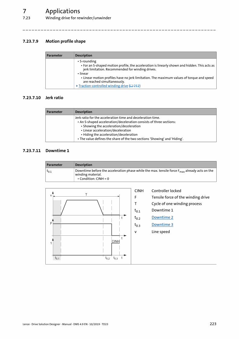
7 Applications7.23 Winding drive for rewinder/unwinder
_ _ _ _ _ _ _ _ _ _ _ _ _ _ _ _ _ _ _ _ _ _ _ _ _ _ _ _ _ _ _ _ _ _ _ _ _ _ _ _ _ _ _ _ _ _ _ _ _ _ _ _ _ _ _ _ _ _ _ _ _ _ _ _
7.23.7.9 Motion profile shape
7.23.7.10 Jerk ratio
7.23.7.11 Downtime 1
Parameter Description
• S-rounding• For an S-shaped motion profile, the acceleration is linearly shown and hidden. This acts as
jerk limitation. Recommended for winding drives.• linear
• Linear motion profiles have no jerk limitation. The maximum values of torque and speed are reached simultaneously.
Traction-controlled winding drive ( 212)
Parameter Description
Jerk ratio for the acceleration time and deceleration time.• An S-shaped acceleration/deceleration consists of three sections:
• Showing the acceleration/deceleration• Linear acceleration/deceleration• Hiding the acceleration/deceleration
• The value defines the share of the two sections 'Showing' and 'Hiding'.
Parameter Description
t0.1 Downtime before the acceleration phase while the max. tensile force Fmax already acts on the winding material.
• Condition: CINH = 0
CINH Controller locked
F Tensile force of the winding drive
T Cycle of one winding process
t0.1 Downtime 1
t0.2 Downtime 2
t0.3 Downtime 3
v Line speed
Tv
t
t0,1 t0,2 t0,3
F
t
1
t
CINH
Lenze · Drive Solution Designer · Manual · DMS 4.9 EN · 10/2019 · TD23 223

7 Applications7.23 Winding drive for rewinder/unwinder
_ _ _ _ _ _ _ _ _ _ _ _ _ _ _ _ _ _ _ _ _ _ _ _ _ _ _ _ _ _ _ _ _ _ _ _ _ _ _ _ _ _ _ _ _ _ _ _ _ _ _ _ _ _ _ _ _ _ _ _ _ _ _ _
7.23.7.12 Downtime 2
7.23.7.13 Downtime 3
Parameter Description
t0.2 Downtime after the deceleration phase while the max. tensile force Fmax still acts on the winding material.
• Condition: CINH = 0
CINH Controller locked
F Tensile force of the winding drive
T Cycle of one winding process
t0.1 Downtime 1
t0.2 Downtime 2
t0.3 Downtime 3
v Line speed
Tv
t
t0,1 t0,2 t0,3
F
t
1
t
CINH
Parameter Description
t0.3 Downtime after the winding process during which no tensile force (Fmax = 0) acts on the winding material.
• The controller is always inhibited during downtime 3. The thermal load of the inverter and the motor is reduced.
CINH Controller locked
F Tensile force of the winding drive
T Cycle of one winding process
t0.1 Downtime 1
t0.2 Downtime 2
t0.3 Downtime 3
v Line speed
Tv
t
t0,1 t0,2 t0,3
F
t
1
t
CINH
224 Lenze · Drive Solution Designer · Manual · DMS 4.9 EN · 10/2019 · TD23

7 Applications7.23 Winding drive for rewinder/unwinder
_ _ _ _ _ _ _ _ _ _ _ _ _ _ _ _ _ _ _ _ _ _ _ _ _ _ _ _ _ _ _ _ _ _ _ _ _ _ _ _ _ _ _ _ _ _ _ _ _ _ _ _ _ _ _ _ _ _ _ _ _ _ _ _
7.23.7.14 Brake at standstill
7.23.7.15 Controller inhibit at standstill
7.23.7.16 Emergency-off time (without material, M-calculation only)
Parameter Description
Active • Yes: The brake is active during downtimes 1 ... 3. If the brake is activated, the motor does not have to provide a torque.
• No: The brake is not active during downtimes 1 ... 3.
Parameter Description
Active • Yes: The controller of the inverter is inhibited during downtimes 1 ... 3. The thermal load of the inverter and the motor is reduced.
• No: The controller of the inverter is enabled during downtimes 1 ... 2.• The controller is always inhibited during downtime 3.
Parameter Description
tES Deceleration time until the drive is at standstill, e.g. if the web breaks.• Only the required motor torque is calculated.• The dimensioning must be checked manually.
Lenze · Drive Solution Designer · Manual · DMS 4.9 EN · 10/2019 · TD23 225

7 Applications7.24 Slider-crank mechanism
_ _ _ _ _ _ _ _ _ _ _ _ _ _ _ _ _ _ _ _ _ _ _ _ _ _ _ _ _ _ _ _ _ _ _ _ _ _ _ _ _ _ _ _ _ _ _ _ _ _ _ _ _ _ _ _ _ _ _ _ _ _ _ _
7.24 Slider-crank mechanism
The rotation of a crank is converted into a translatory motion that oscillates between two deadcentres by means of a slider-crank mechanism.
The fixed point in the application is the crankshaft where the input speed is applied. It is possible totransmit high forces and implement energetically favorable movements.
The nonlinear mechanics of the slider-crank mechanism are widely used in practice. Typicalapplications:
• Crank lifter in materials handling technology
• Crank press for benders and punching devices
• Pusher
The mechanics of the slider-crank mechanism moves in two dimensions, on the X axis (horizontal)and the Z axis (vertical). The gravitation acts with 9.81 m/s² in negative direction of the Z axis. TheY axis is not relevant.
The position of the slider-crank mechanism determined via the angle of tilt . This serves to sizeboth horizontal and vertical slider-crank mechanisms. The slider path can also be sized on aninclined plane.
Depending on the type of mechanics, a sliding friction must be considered for the linear guide of theslider path. The friction in the pivot points can be neglected.
More process forces acting on the slider such as punching or joining forces can be indicated ascounterforces Fvs.
The nonlinear mechanics cause an alternating torque load for the drive at continuous speed. Thespeed at the drive bearing of the crank (crankshaft) can be specified with a continuous speed or witha clocked speed profile.
Note!
Motion profiles are specified via the MotionDesigner. Here, individual motion profiles can be created or imported.
226 Lenze · Drive Solution Designer · Manual · DMS 4.9 EN · 10/2019 · TD23

7 Applications7.24 Slider-crank mechanism
_ _ _ _ _ _ _ _ _ _ _ _ _ _ _ _ _ _ _ _ _ _ _ _ _ _ _ _ _ _ _ _ _ _ _ _ _ _ _ _ _ _ _ _ _ _ _ _ _ _ _ _ _ _ _ _ _ _ _ _ _ _ _ _
7.24.1 Angle of tilt of the slider-crank mechanism
The angle of tilt defines the orientation of the slider path:
• Alignment in positive X direction defines = 0°. This corresponds to an orientation of the slider path in 3 o'clock position.
• The angle of tilt is defined as positive counterclockwise.
[7-253] Angle of tilt for the typical orientations
= 0° Horizontal slider-crank mechanism with slider path in positive X direction (3 o'clock position)
= 90° Crank lifter (slider path in 12 o'clock position)
= 180° Horizontal slider-crank mechanism with slider path in negative X direction (9 o'clock position)
= 270° Crank press (slider path in 6 o'clock position)
Lenze · Drive Solution Designer · Manual · DMS 4.9 EN · 10/2019 · TD23 227

7 Applications7.24 Slider-crank mechanism
_ _ _ _ _ _ _ _ _ _ _ _ _ _ _ _ _ _ _ _ _ _ _ _ _ _ _ _ _ _ _ _ _ _ _ _ _ _ _ _ _ _ _ _ _ _ _ _ _ _ _ _ _ _ _ _ _ _ _ _ _ _ _ _
[7-254] Example: slider-crank mechanism on an inclined plane and offset of the slider path
7.24.2 Physical data on crank rod and crank disk
> 0 = 8°0 = 240°
Crank rod Crank disk
Parameters for describing the body
lCnk Length of the crank rod lCnk effective radius of the crank disk
mCnk Mass of the crank rod
The crank rod is assumed to be a thin rod with a homogeneous mass distribution.
Determination of the inertia The inertia is directly entered as Jadd.
DSD automatically determines the inertia from the mass mCnk and the length lCnk.
JCnk Jadd13--- mCnk lCnk
2 +=
228 Lenze · Drive Solution Designer · Manual · DMS 4.9 EN · 10/2019 · TD23
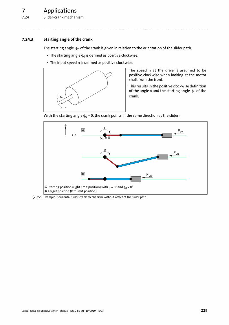
7 Applications7.24 Slider-crank mechanism
_ _ _ _ _ _ _ _ _ _ _ _ _ _ _ _ _ _ _ _ _ _ _ _ _ _ _ _ _ _ _ _ _ _ _ _ _ _ _ _ _ _ _ _ _ _ _ _ _ _ _ _ _ _ _ _ _ _ _ _ _ _ _ _
7.24.3 Starting angle of the crank
The starting angle 0 of the crank is given in relation to the orientation of the slider path.
• The starting angle 0 is defined as positive clockwise.
• The input speed n is defined as positive clockwise.
With the starting angle 0 = 0, the crank points in the same direction as the slider:
[7-255] Example: horizontal slider-crank mechanism without offset of the slider path
The speed n at the drive is assumed to bepositive clockwise when looking at the motorshaft from the front.
This results in the positive clockwise definitionof the angle and the starting angle 0 of thecrank.
Starting position (right limit position) with = 0° and 0 = 0° Target position (left limit position)
Lenze · Drive Solution Designer · Manual · DMS 4.9 EN · 10/2019 · TD23 229

7 Applications7.24 Slider-crank mechanism
_ _ _ _ _ _ _ _ _ _ _ _ _ _ _ _ _ _ _ _ _ _ _ _ _ _ _ _ _ _ _ _ _ _ _ _ _ _ _ _ _ _ _ _ _ _ _ _ _ _ _ _ _ _ _ _ _ _ _ _ _ _ _ _
With the starting angle 0 = 180°, the crank points in the opposite direction as the slider:
[7-256] Example: typical motion sequence of a crank press without an offset of the slider path
Tip!
Often, a timed speed profile is defined for the crankshaft. For moving from a starting position to a target position, the crank must be rotated by a certain angle (e.g. 180°).• The angle can be entered in the MotionDesigner in the Basic values area if "Angle/time"
is set in the specification.
"Profile" tab ( 264)
Upper dead centre (starting position) with = 270° and 0 = 180° Lower dead centre (target position)
230 Lenze · Drive Solution Designer · Manual · DMS 4.9 EN · 10/2019 · TD23

7 Applications7.24 Slider-crank mechanism
_ _ _ _ _ _ _ _ _ _ _ _ _ _ _ _ _ _ _ _ _ _ _ _ _ _ _ _ _ _ _ _ _ _ _ _ _ _ _ _ _ _ _ _ _ _ _ _ _ _ _ _ _ _ _ _ _ _ _ _ _ _ _ _
7.24.4 Offset of slider path
defines the offset between the slider path and the axis where the drive bearing of the crank islocated.
In most applications, there is no offset of the slider path ( = 0). For applications with an offset of theslider path ( 0), the parameter setting is described in this chapter.
With an angle of tilt = 0° and a shift in positive Z direction, the parameter value is positive (seefigure [7-259]).
Slider path with an offset 0:
[7-257] Example: crank lifter with an offset of the slider path
Slider path with an offset 0:
[7-258] Example: horizontal slider-crank mechanism with the orientation of the slider path in negative X direction
0 = 90°0 = 180°
0 (negative offset of the slider path) = 180°0 = 195°
Lenze · Drive Solution Designer · Manual · DMS 4.9 EN · 10/2019 · TD23 231
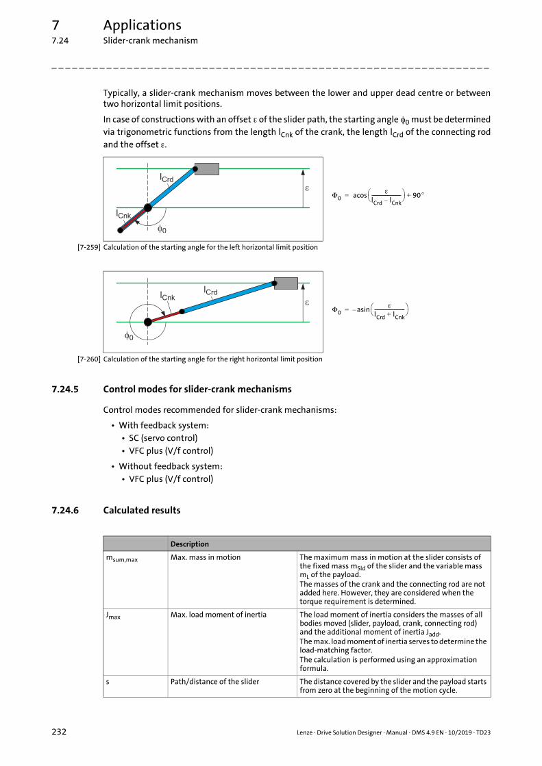
7 Applications7.24 Slider-crank mechanism
_ _ _ _ _ _ _ _ _ _ _ _ _ _ _ _ _ _ _ _ _ _ _ _ _ _ _ _ _ _ _ _ _ _ _ _ _ _ _ _ _ _ _ _ _ _ _ _ _ _ _ _ _ _ _ _ _ _ _ _ _ _ _ _
Typically, a slider-crank mechanism moves between the lower and upper dead centre or betweentwo horizontal limit positions.
In case of constructions with an offset of the slider path, the starting angle 0 must be determinedvia trigonometric functions from the length lCnk of the crank, the length lCrd of the connecting rodand the offset .
[7-259] Calculation of the starting angle for the left horizontal limit position
[7-260] Calculation of the starting angle for the right horizontal limit position
7.24.5 Control modes for slider-crank mechanisms
Control modes recommended for slider-crank mechanisms:
• With feedback system:• SC (servo control)• VFC plus (V/f control)
• Without feedback system:• VFC plus (V/f control)
7.24.6 Calculated results
0
lCrd lCnk–------------------------ 90+acos=
0
lCrd lCnk+------------------------- asin–=
Description
msum,max Max. mass in motion The maximum mass in motion at the slider consists of the fixed mass mSld of the slider and the variable mass mL of the payload.The masses of the crank and the connecting rod are not added here. However, they are considered when the torque requirement is determined.
Jmax Max. load moment of inertia The load moment of inertia considers the masses of all bodies moved (slider, payload, crank, connecting rod) and the additional moment of inertia Jadd.The max. load moment of inertia serves to determine the load-matching factor.The calculation is performed using an approximation formula.
s Path/distance of the slider The distance covered by the slider and the payload starts from zero at the beginning of the motion cycle.
232 Lenze · Drive Solution Designer · Manual · DMS 4.9 EN · 10/2019 · TD23
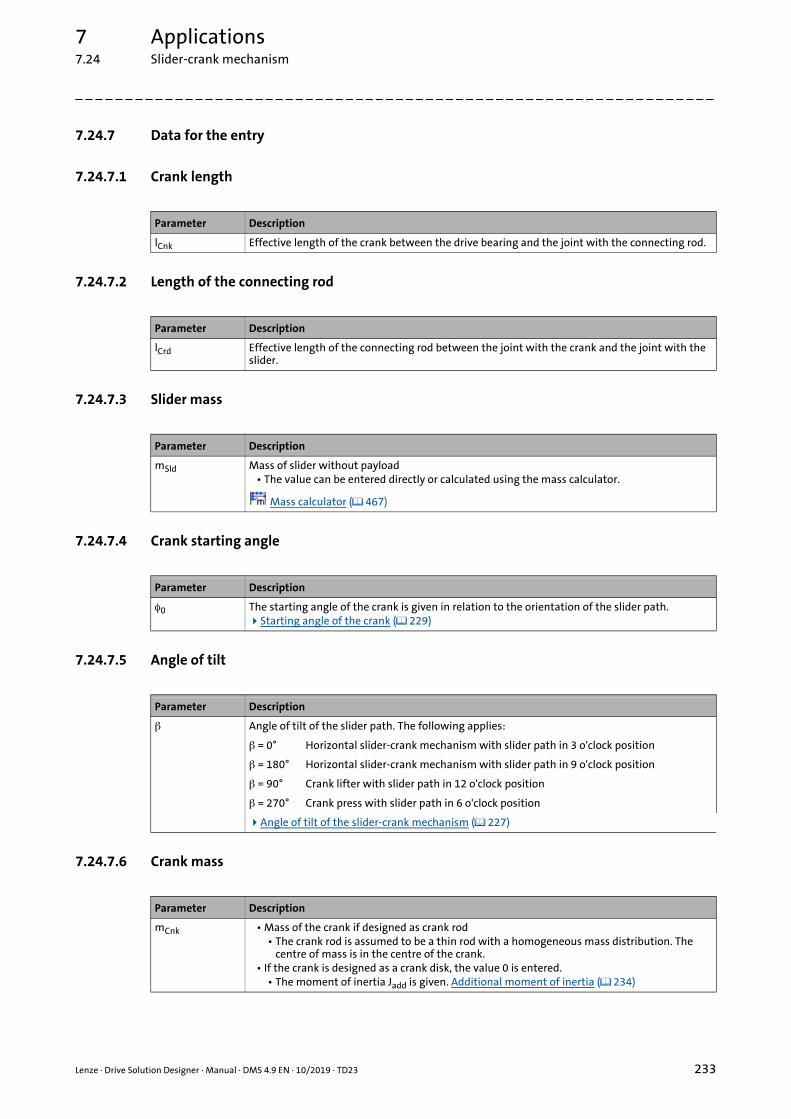
7 Applications7.24 Slider-crank mechanism
_ _ _ _ _ _ _ _ _ _ _ _ _ _ _ _ _ _ _ _ _ _ _ _ _ _ _ _ _ _ _ _ _ _ _ _ _ _ _ _ _ _ _ _ _ _ _ _ _ _ _ _ _ _ _ _ _ _ _ _ _ _ _ _
7.24.7 Data for the entry
7.24.7.1 Crank length
7.24.7.2 Length of the connecting rod
7.24.7.3 Slider mass
7.24.7.4 Crank starting angle
7.24.7.5 Angle of tilt
7.24.7.6 Crank mass
Parameter Description
lCnk Effective length of the crank between the drive bearing and the joint with the connecting rod.
Parameter Description
lCrd Effective length of the connecting rod between the joint with the crank and the joint with the slider.
Parameter Description
mSld Mass of slider without payload• The value can be entered directly or calculated using the mass calculator.
Mass calculator ( 467)
Parameter Description
0 The starting angle of the crank is given in relation to the orientation of the slider path.Starting angle of the crank ( 229)
Parameter Description
Angle of tilt of the slider path. The following applies:
= 0° Horizontal slider-crank mechanism with slider path in 3 o'clock position
= 180° Horizontal slider-crank mechanism with slider path in 9 o'clock position
= 90° Crank lifter with slider path in 12 o'clock position
= 270° Crank press with slider path in 6 o'clock position
Angle of tilt of the slider-crank mechanism ( 227)
Parameter Description
mCnk • Mass of the crank if designed as crank rod• The crank rod is assumed to be a thin rod with a homogeneous mass distribution. The
centre of mass is in the centre of the crank.• If the crank is designed as a crank disk, the value 0 is entered.
• The moment of inertia Jadd is given. Additional moment of inertia ( 234)
Lenze · Drive Solution Designer · Manual · DMS 4.9 EN · 10/2019 · TD23 233

7 Applications7.24 Slider-crank mechanism
_ _ _ _ _ _ _ _ _ _ _ _ _ _ _ _ _ _ _ _ _ _ _ _ _ _ _ _ _ _ _ _ _ _ _ _ _ _ _ _ _ _ _ _ _ _ _ _ _ _ _ _ _ _ _ _ _ _ _ _ _ _ _ _
7.24.7.7 Mass of the connecting rod
7.24.7.8 Coefficient of friction of the guide rail
7.24.7.9 Offset of slider path
7.24.7.10 Additional moment of inertia
7.24.7.11 Speed
7.24.7.12 Mass of the payload
Parameter Description
mCrd Mass of the connecting rod• The connecting rod is assumed to be a thin rod with a homogeneous mass distribution. The
centre of mass is in the centre of the connecting rod.
Parameter Description
μGdn Coefficient of sliding friction of the guide rail• Value can be entered directly or selected from the "Physical coefficients" table.Physical coefficients ( 485)
Coefficient of sliding friction
Parameter Description
Offset between the slider path and the axis where the drive bearing of the crank is located.• With an angle of tilt = 0° and a shift in positive Z direction, the parameter value is positive.Offset of slider path ( 231)
Parameter Description
Jadd The additional moment of inertia acts on the drive bearing of the crank.• If the crank is designed as a crank disk, the moment of inertia of the crank disk is entered.• Value can be entered directly or calculated using the inertial calculator.
Inertial calculator ( 469)
Parameter Description
n Speed at the drive bearing of the crank• Value is entered in the Motion dimensioning step.
Parameter Description
mL Mass of payload• Value is entered in the Motion dimensioning step.
234 Lenze · Drive Solution Designer · Manual · DMS 4.9 EN · 10/2019 · TD23

7 Applications7.24 Slider-crank mechanism
_ _ _ _ _ _ _ _ _ _ _ _ _ _ _ _ _ _ _ _ _ _ _ _ _ _ _ _ _ _ _ _ _ _ _ _ _ _ _ _ _ _ _ _ _ _ _ _ _ _ _ _ _ _ _ _ _ _ _ _ _ _ _ _
7.24.7.13 Counterforce
Parameter Description
Fvs Force that counteracts the moving direction of the slider. The force acts on the slider.• Value is entered in the Motion dimensioning step.
The sign of the counterforce determines its effective direction.• If the speed is positive,
• positive values act opposite to the moving direction,• negative values act with the moving direction.
• If the speed is negative,• positive value act with the moving direction,• negative values act opposite to the moving direction.
Note!
If the force acts in a supporting manner, the opposite sign is to be entered.
Lenze · Drive Solution Designer · Manual · DMS 4.9 EN · 10/2019 · TD23 235

7 Applications7.25 Eccentric lift table
_ _ _ _ _ _ _ _ _ _ _ _ _ _ _ _ _ _ _ _ _ _ _ _ _ _ _ _ _ _ _ _ _ _ _ _ _ _ _ _ _ _ _ _ _ _ _ _ _ _ _ _ _ _ _ _ _ _ _ _ _ _ _ _
7.25 Eccentric lift table
Eccentric lift tables are used to overcome a low lifting height in materials handling technology, e.g.in the warehouse logistics and automobile production industry sectors.
Typical applications are:
• Raise/lower a conveyor track, e.g. in a corner transfer unit.
• Level compensation in a conveyor line.
The rotation of the drive of an eccentric lifter is converted into a translatory motion that oscillatesbetween two dead centres by means of an eccentric disk.
A fixed point in the system is the drive shaft to which the input speed is applied.
The nonlinear mechanics cause an alternating torque load for the drive at continuous speed.
• The eccentric lift table is moved vertically. The hoist axis is the positive Z axis.
• The gravitation acts with 9.81 m/s² in a negative Z direction.
• The friction between the eccentric disk and the lift table’s support is disregarded.
• More process forces acting on the eccentric lift table such as joining forces can be indicated as counterforces Fvs.
• The eccentric lift table can be operated with a continuous or clocked speed. The speed is preselected at the drive’s inverter.
Note!
Motion profiles are specified via the MotionDesigner. Here, individual motion profiles can be created or imported.
236 Lenze · Drive Solution Designer · Manual · DMS 4.9 EN · 10/2019 · TD23

7 Applications7.25 Eccentric lift table
_ _ _ _ _ _ _ _ _ _ _ _ _ _ _ _ _ _ _ _ _ _ _ _ _ _ _ _ _ _ _ _ _ _ _ _ _ _ _ _ _ _ _ _ _ _ _ _ _ _ _ _ _ _ _ _ _ _ _ _ _ _ _ _
7.25.1 Starting angle of the eccentric disk
The starting angle 0 of the eccentric disk is given in relation to the orientation of the hoist axis.
• The starting angle 0 is defined as positive clockwise.
• The input speed n is defined as positive clockwise.
Typical motion sequence of an eccentric lift table
In the starting position, the lift table is at lower dead centre . After one rotation of the drive shaft(connected to the eccentric disk), the lift table is in the target position at upper dead centre .
With the starting angle 0 = 180, the eccentric disk points in the same direction as the hoist axis:
[7-261] Example: Typical motion sequence of an eccentric lift table
Tip!
For the movement from the starting position to the target position, the eccentric disk mustbe rotated by a certain angle (e.g. 180°).• If a clocked speed profile has to be specified, the angle can be entered in the
MotionDesigner under "Profile" tab in the Basic values area. "Angle/time" has to be set in the specification for this purpose.
The speed n at the drive is assumed to bepositive clockwise when looking at the driveshaft from the front.
This results in the positive clockwise definitionof the angle and the starting angle 0 of theeccentric disk.
Starting position with 0 = 180° (lower dead centre) Target position (upper dead centre)
Lenze · Drive Solution Designer · Manual · DMS 4.9 EN · 10/2019 · TD23 237

7 Applications7.25 Eccentric lift table
_ _ _ _ _ _ _ _ _ _ _ _ _ _ _ _ _ _ _ _ _ _ _ _ _ _ _ _ _ _ _ _ _ _ _ _ _ _ _ _ _ _ _ _ _ _ _ _ _ _ _ _ _ _ _ _ _ _ _ _ _ _ _ _
7.25.2 Data for the entry
7.25.2.1 Eccentricity
7.25.2.2 Mass of the lift table
7.25.2.3 Eccentric disk starting angle
7.25.2.4 Mass of the eccentric disk
7.25.2.5 Additional moment of inertia
7.25.2.6 Speed
Parameter Description
lEcc Offset between the drive bearing and the centre of the eccentric disk.
Parameter Description
mLft Mass of the lift table without payload.• The value can be entered directly or calculated using the mass calculator.
Mass calculator ( 467)
Parameter Description
0 The starting angle of the eccentric disk is given as positive clockwise in relation to the orientation of the hoist axis (Z axis).Starting angle of the eccentric disk ( 237)
Parameter Description
mEcc Mass of the eccentric disk with the centre of the mass in the centre of the disk.• The value can be entered directly or calculated using the mass calculator.
Mass calculator ( 467)
Parameter Description
Jadd The additional moment of inertia acts on the drive bearing, e.g. moment of inertia of the eccentric disk.
• Value can be entered directly or calculated using the inertial calculator.
Inertial calculator ( 469)
Parameter Description
n Speed at the drive shaft• Value is entered in the Motion dimensioning step.
238 Lenze · Drive Solution Designer · Manual · DMS 4.9 EN · 10/2019 · TD23

7 Applications7.25 Eccentric lift table
_ _ _ _ _ _ _ _ _ _ _ _ _ _ _ _ _ _ _ _ _ _ _ _ _ _ _ _ _ _ _ _ _ _ _ _ _ _ _ _ _ _ _ _ _ _ _ _ _ _ _ _ _ _ _ _ _ _ _ _ _ _ _ _
7.25.2.7 Mass of the payload
7.25.2.8 Counterforce
7.25.2.9 Max. mass in motion
7.25.2.10 Max. load moment of inertia
7.25.2.11 Path/distance of the lift table
Parameter Description
mL Mass of payload• Value is entered in the Motion dimensioning step.
Parameter Description
Fvs Force that works against the direction of movement. The force acts on the lift table.• Value is entered in the Motion dimensioning step.
The sign of the counterforce determines its effective direction.• If the speed is positive,
• positive values act opposite to the moving direction,• negative values act with the moving direction.
• If the speed is negative,• positive value act with the moving direction,• negative values act opposite to the moving direction.
Note!
If the force acts in a supporting manner, the opposite sign is to be entered.
Parameter Description
msum,max The maximum mass in motion consists of the fixed mass mLft of the lift table and the variable mass mL of the payload.
• The mass of the eccentric disk is not added here. However, it is considered when the torque requirement is determined.
Parameter Description
Jmax The load moment of inertia or moment of inertia of the application considers the masses of all moving bodies such as lift table, payload and the additional moment of inertia Jadd.
• The max. load moment of inertia serves to determine the load-matching factor.• An approximate formula is used for the calculation.
Parameter Description
s The distance travelled by the lift table with the payload.• The distance s begins at zero at the start of the motion cycle.
Lenze · Drive Solution Designer · Manual · DMS 4.9 EN · 10/2019 · TD23 239

8 Motion design8.1 Selection of motion profile
_ _ _ _ _ _ _ _ _ _ _ _ _ _ _ _ _ _ _ _ _ _ _ _ _ _ _ _ _ _ _ _ _ _ _ _ _ _ _ _ _ _ _ _ _ _ _ _ _ _ _ _ _ _ _ _ _ _ _ _ _ _ _ _
8 Motion design
The motion design describes how the application is to move. It is distinguished between rectilinearmotion (translatory) and rotary motion.
• Quantities of a translatory motion: path, speed, acceleration.
• Quantities of a rotary motion: angle of rotation, angular velocity, angular acceleration.
The following chapters describe the various options how to create motion profiles for your drive inthe DSD.
8.1 Selection of motion profile
Select how you would like to create the motion profile.
Create, import motion profile
User-definable motion profile, used for simulating operating modesS8, S9 and S10. The edition is carried out with the MotionDesigner( 241).
You have several options to create motion profiles:
• Parameters for motion, acceleration and jerk, if required.
• Create and compose linear, trapezoidal or S-shaped subprofiles graphically.
• Load already available motion profiles in lmp format.
• Import motion profiles from older DSD versions in dpr format.
• Import operating points from an ASCII file.• Apart from linear motion profiles, like this also s-shaped and
sin²-shaped motion profiles can be created.
Predefined motion profile according to operating mode ( 286)
Motion profile according to VDE 0530. Operating modes S1, S2, S3 orS6 can be selected.
• Depending on the starting time and deceleration time, operating modes S4, S5 or S7 can also be simulated.
240 Lenze · Drive Solution Designer · Manual · DMS 4.9 EN · 10/2019 · TD23

8 Motion design8.2 MotionDesigner
_ _ _ _ _ _ _ _ _ _ _ _ _ _ _ _ _ _ _ _ _ _ _ _ _ _ _ _ _ _ _ _ _ _ _ _ _ _ _ _ _ _ _ _ _ _ _ _ _ _ _ _ _ _ _ _ _ _ _ _ _ _ _ _
8.2 MotionDesigner
The MotionDesigner serves to create, process and manage motion profiles. The two options to openthe MotionDesigner offer a flexible application. Either you create a motion profile during the drivedimensioning phase or you use it independent of it.
Application ranges:
How to open the independent MotionDesigner:
Click on the icon in the toolbar.- or -Execute the Tools MotionDesigner command.
How to open the application-dependent MotionDesigner:
Click the MotionDesigner button in the "Motion" dimensioning step.
Quickly finding the information required:
Independent MotionDesigner Application-dependent MotionDesigner
• Creating motion profiles for coordinated axis drives of a multi-axis application.
• Importing, processing and saving individual, standardised motion profiles.
• Creating the motion profiles of all drive axes simultaneously and coordinating them on a joint time axis.• Each motion profile can be saved separately and
loaded into the project of the corresponding drive axis.
• Creating a motion profile for the selected application.• The project can be an individual application or an
uncoordinated drive axis in a multi-axis system.• The MotionDesigner is opened automatically when
the "Motion" dimensioning step is reached.
• Control and function elements ( 242) • Toolbar ( 243) • Object area ( 245)
• Load the motion profile ( 250) • Save motion profile ( 251) • Processing functions ( 245) • Object properties ( 247) • Exporting profile data ( 251) • Importing profile data ( 252) • Error messages during import ( 254)
• Screen divider ( 244)
• Graphic area ( 255) • Creating motion profiles: Principles ( 255) • Creating a parameter profile: Principles ( 256) • Setting XY axes ( 257) • Creating and editing elements ( 258) • Error messages ( 262)
• Parameter area: Description ( 263) • "Profile" tab ( 264) • "Line" tab: Motion profile ( 266) • "Line" tab": Parameter profile ( 267) • "S-edge" tab ( 269) • "Imported profile" tab ( 270)
Lenze · Drive Solution Designer · Manual · DMS 4.9 EN · 10/2019 · TD23 241

8 Motion design8.2 MotionDesigner
_ _ _ _ _ _ _ _ _ _ _ _ _ _ _ _ _ _ _ _ _ _ _ _ _ _ _ _ _ _ _ _ _ _ _ _ _ _ _ _ _ _ _ _ _ _ _ _ _ _ _ _ _ _ _ _ _ _ _ _ _ _ _ _
8.2.1 Control and function elements
The user interface has the following control and function elements:
Toolbar ( 243)
Object area ( 245)
Screen divider ( 244)
Graphic area ( 255)
Parameter area: Description ( 263)
Accept button with the application-dependent MotionDesigner• Accept changes and exit the MotionDesigner.
Close button with the independent MotionDesigner.• Exit the MotionDesigner.
Discard changes and exit the MotionDesigner.• Only available with the application-dependent MotionDesigner.
242 Lenze · Drive Solution Designer · Manual · DMS 4.9 EN · 10/2019 · TD23

8 Motion design8.2 MotionDesigner
_ _ _ _ _ _ _ _ _ _ _ _ _ _ _ _ _ _ _ _ _ _ _ _ _ _ _ _ _ _ _ _ _ _ _ _ _ _ _ _ _ _ _ _ _ _ _ _ _ _ _ _ _ _ _ _ _ _ _ _ _ _ _ _
8.2.2 Toolbar
Click on an icon to carry out the respective function.
Symbol Keyboard command
Function
<Ctrl>+<N> Create new motion profile.
<Ctrl>+<O> Load motion profile.Load the motion profile ( 250)
<Ctrl>+<S> Save motion profile.• When a newly created motion profile is saved, you are asked for the
destination of the Imp file.• When the motion profile is newly saved, the Imp file is updated.Save motion profile ( 251)
– Import the motion profile with parameter profiles from an ASCII file.Importing profile data ( 252)
– Create note for motion profile• The note is attached to the "Motion" dimensioning step.• The function is only available with the application-dependent
MotionDesigner.Notes ( 37)
<Del> Delete highlighted element.• The element is deleted permanently.
– Application analysis.• Shows diagrams and table of values via the entered and calculated values
with regard to a cycle of the motion profile.• The function is only available with the application-dependent
MotionDesigner.
<Ctrl>+<Z> Undo last action.
<Ctrl>+<Y> Redo last undone action.
– Default settings for the dialog box.• Identical to the "Motion" register in the DSD menu ExtrasSettings.Settings ( 42) "Motion" register ( 43)
– Zoom x-axis and y-axis• Draw up a rectangle across the area to be zoomed in by keeping the left
mouse button pressed.
– Return to standard view.
<Ctrl>+<X> Cut the highlighted element and drag to the clipboard.
<Ctrl>+<C> Copy the highlighted element into the clipboard.
<Ctrl>+<V> Paste the element from the clipboard.
– Select the element or deactivate an active symbol.
– Draw trapezoidal element.• The "Profile" register contains a selection of trapezoidal elements.Creating and editing elements ( 258) Parameter area: Description ( 263)
Lenze · Drive Solution Designer · Manual · DMS 4.9 EN · 10/2019 · TD23 243

8 Motion design8.2 MotionDesigner
_ _ _ _ _ _ _ _ _ _ _ _ _ _ _ _ _ _ _ _ _ _ _ _ _ _ _ _ _ _ _ _ _ _ _ _ _ _ _ _ _ _ _ _ _ _ _ _ _ _ _ _ _ _ _ _ _ _ _ _ _ _ _ _
8.2.3 Screen divider
By dragging the screen divider, the size of the Object area or the drawing area is changedhorizontally.
How to drag the screen divider:
1. Move the mouse pointer over the screen divider until it is visible as two vertical lines.
2. Press the left mouse button and drag the screen divider.
3. Release the mouse button at the desired position.
– Draw line.Creating and editing elements ( 258)
– Draw S-shaped element.Creating and editing elements ( 258)
– Import an individual motion profile or parameter profile.Importing profile data ( 252)
– Move elements to the left.• Moves separated elements on the drawing area to the left and connects them
to its preceding element.Shift elements automatically to the left ( 260)
– Combines the elements that form a trapezium so that an element is generated.• Only connected elements can be combined.• The elements to be combined must be highlighted.Combining elements ( 261)
– Undo combination.• Deactivate the combination of a trapezoidal element so that the elements
can be processed separately.
– Reflect highlighted element on the time axis.• This function can only be accessed via the context menu (click the left mouse
button).
– <Ctrl>+<Click> Duplicates an element in the drawing area when the element is left-clicked while the Ctrl key is pressed.
– <Ctrl>+<G> Shows or hides the grid of the drawing area.
– <Ctrl>+<A> Highlights all elements on the drawing area.
– <Shift>+<Click> In order to highlight several elements keep the <Shift> button pressed and left-click the elements.
Symbol Keyboard command
Function
244 Lenze · Drive Solution Designer · Manual · DMS 4.9 EN · 10/2019 · TD23

8 Motion design8.2 MotionDesigner
_ _ _ _ _ _ _ _ _ _ _ _ _ _ _ _ _ _ _ _ _ _ _ _ _ _ _ _ _ _ _ _ _ _ _ _ _ _ _ _ _ _ _ _ _ _ _ _ _ _ _ _ _ _ _ _ _ _ _ _ _ _ _ _
8.2.4 Object area
The Object area indicates the arrangement of the objects (motion profile, parameter). Use theProcessing functions to process the objects.
8.2.4.1 Processing functions
Processing functions can only be executed via the context menu. Which processing functions areavailable depends on different conditions:
• If you create motion profiles and parameters in the independent MotionDesigner, all editing functions are available.
• If a motion profile with parameters has been created in the application-dependent MotionDesigner, only the object properties can be edited.
Legend Information
Motion profile
Parameter
Lenze · Drive Solution Designer · Manual · DMS 4.9 EN · 10/2019 · TD23 245

8 Motion design8.2 MotionDesigner
_ _ _ _ _ _ _ _ _ _ _ _ _ _ _ _ _ _ _ _ _ _ _ _ _ _ _ _ _ _ _ _ _ _ _ _ _ _ _ _ _ _ _ _ _ _ _ _ _ _ _ _ _ _ _ _ _ _ _ _ _ _ _ _
Overview of the editing functions that can be called in the Object area via the context menu (rightmouse button).
Symbol Processing function
Create motion profile• Available with the independent MotionDesigner.• Place the mouse pointer in the Object area on a free space and select Add motion profile in the
context menu.
Create parameters independent of the motion profile• Available with the independent MotionDesigner.• Place the mouse pointer in the Object area on a free space and select Add parameter in the
context menu.
Add parameters to a motion profile• Available for motion profiles that were created with the independent MotionDesigner.• Highlight the motion profile and select Add parameters in the context menu.
Copy parameters into the clipboard.• Available for parameters that were created with the independent MotionDesigner.• Highlight parameters and select Copy object in the context menu.
Copy motion profile into the clipboard.• Available with the independent MotionDesigner.• Highlight the motion profile and select Copy object in the context menu.
Paste copied parameter from the clipboard.• Available for parameters that were created with the independent MotionDesigner.• Highlight the motion profile and select Paste object in the context menu.
Paste copied motion profile from the clipboard.• Available with the independent MotionDesigner.• Place the mouse pointer in the Object area on a free space and select Paste object in the context
menu.
Delete highlighted motion profile or parameter permanently.• Available for motion profiles that were created with the independent MotionDesigner.• Highlight a motion profile or parameter and select Delete object in the context menu.
Call object properties.• Highlight a motion profile or parameter and select Object properties in the context menu.Object properties ( 247)
Export motion profile or parameter into an ASCII file.• Highlight a motion profile or parameter and select Export profile data in the context menu.Exporting profile data ( 251)
Import the motion profile with the corresponding parameters from an ASCII file.• Highlight the motion profile and select Import profile data in the context menu.Importing profile data ( 252)
Update imported motion profile if data in the ASCII file has been changed.• Only available for imported motion profiles.• Highlight the motion profile and select Update in the context menu.• If import data in the ASCII file is changed, this command serves to import the data again.
Note:• During import, a linking to the ASCII file is established. The linking is preserved even after the
motion profile (Imp file) is saved. If the absolute data path changes, the linking gets lost.Importing profile data ( 252)
246 Lenze · Drive Solution Designer · Manual · DMS 4.9 EN · 10/2019 · TD23

8 Motion design8.2 MotionDesigner
_ _ _ _ _ _ _ _ _ _ _ _ _ _ _ _ _ _ _ _ _ _ _ _ _ _ _ _ _ _ _ _ _ _ _ _ _ _ _ _ _ _ _ _ _ _ _ _ _ _ _ _ _ _ _ _ _ _ _ _ _ _ _ _
8.2.4.2 Object properties
Motion profile
Highlight the motion profile, press the right mouse button and select Object properties from the context menu to open the Object properties dialog box.
Legend Description
Name of motion profile.• Click into the input field and enter a name for the motion profile.Creating motion profiles: Principles ( 255)
Selection of the motion• Click into the list field to select a translatory or rotary motion profile.• The selection is only possible if the motion profile has been created with the independent
MotionDesigner.
Selection of the line colour.• The motion profile is displayed in this colour on the drawing area in the background.• Click the button to open the dialog box for selecting the desired colour.Graphic area ( 255)
Display of the motion profile in the background• When you select a parameter, the motion profile remains visible on the drawing area in the
background.Graphic area ( 255)
Field activated: Motion profile is visible.
Field deactivated: Motion profile is invisible.
Lenze · Drive Solution Designer · Manual · DMS 4.9 EN · 10/2019 · TD23 247

8 Motion design8.2 MotionDesigner
_ _ _ _ _ _ _ _ _ _ _ _ _ _ _ _ _ _ _ _ _ _ _ _ _ _ _ _ _ _ _ _ _ _ _ _ _ _ _ _ _ _ _ _ _ _ _ _ _ _ _ _ _ _ _ _ _ _ _ _ _ _ _ _
Parameter
Highlight the parameter, press the right mouse button and select Object properties from the context menu to open the Object properties dialog box.
Legend Description
Parameter name.• Click into the input field and enter a name for the parameter.Creating a parameter profile: Principles ( 256)
Selection of the parameter.• Click into the list field and select the desired parameter.• Possible selection: Mass of payload, counterforce, moment of inertia, torque, brake, controller
inhibit.• The selection is only possible if the parameter has been created with the independent
MotionDesigner.
Selection of the line colour.• The parameter profile is displayed in this colour on the drawing area in the background.• Click the button to open the dialog box for selecting the desired colour.Graphic area ( 255)
Display of the parameter profile in the background• When you select other parameters, the motion profile remains visible on the drawing area in the
background.Graphic area ( 255)
Field activated: Motion profile is visible.
Field deactivated: Motion profile is invisible.
248 Lenze · Drive Solution Designer · Manual · DMS 4.9 EN · 10/2019 · TD23

8 Motion design8.2 MotionDesigner
_ _ _ _ _ _ _ _ _ _ _ _ _ _ _ _ _ _ _ _ _ _ _ _ _ _ _ _ _ _ _ _ _ _ _ _ _ _ _ _ _ _ _ _ _ _ _ _ _ _ _ _ _ _ _ _ _ _ _ _ _ _ _ _
Selection whether elements of the parameter may have linearly changeable values.• Field activated: You can only enter one value. The element entered changes erratically between
the previous value and the input value.• Field deactivated: You can enter two values. The entered element linearly changes between
these two values.• No selection is possible for the "brake" and "controller inhibit" parameters, as these control
signals can only have the states 1 or 0.• Special features:
• Selection possible in the independent MotionDesigner.• Selection possible in the application-dependent MotionDesigner if a motion profile created in
the independent MotionDesigner is loaded.• In the case of a mass of the payload that can be linearly changed, the force resulting from the
mass alteration is not taken into consideration.• In the case of an inertia that can be linearly changed, the torque resulting from the change in
inertia is not taken into consideration.Please note:Continuous or erratic changes of the mass during motion which have an impact on the torque are not taken into consideration for the calculation in DSD.Creating a parameter profile: Principles ( 256)
Default value for the parameter.• The parameter is automatically created with this standard value.• The entry of more line elements creates an individual parameter profile.• The "brake" and "controller inhibit" parameters do not have a default value as these control
signals can only have the states 1 or 0.Creating a parameter profile: Principles ( 256)
Legend Description
Lenze · Drive Solution Designer · Manual · DMS 4.9 EN · 10/2019 · TD23 249

8 Motion design8.2 MotionDesigner
_ _ _ _ _ _ _ _ _ _ _ _ _ _ _ _ _ _ _ _ _ _ _ _ _ _ _ _ _ _ _ _ _ _ _ _ _ _ _ _ _ _ _ _ _ _ _ _ _ _ _ _ _ _ _ _ _ _ _ _ _ _ _ _
8.2.5 Managing motion profiles
The MotionDesigner provides three formats for the management of the motion profiles andparameters.
8.2.5.1 Load the motion profile
How to load a motion profile:
1. Click the icon in the toolbar.
2. In the Load motion profile dialog box, select a motion profile in the *.lmp format and activate the Open button.• It is only possible to load motion profiles that have been saved in DSD.• When the motion profile is loaded, it is checked whether the motion (translatory or
rotary) matches the application.• If the motion profile contains working points with high values, the scaling in the Graphic
area is adapted automatically.
File extension Format Description
lmp Lenze Motion Profile The MotionDesigner saves and opens motion profiles in this format.
• Created motion profiles are upwards compatible. They can be opened with previous DSD versions. There is no downward compatibility.
txt ASCII file The MotionDesigner can import or export motion profiles and parameters in the txt format.
• It is possible to export CAM curve profiles in the txt format with the CamManager in the »Engineer«.
dpr Motion profile from a previous DSD version.• Files in the dpr format can only be imported in the
MotionDesigner.
Note!
• In the dimensioning-dependent MotionDesigner, you can only load motion profiles that match the motion (translatory or rotary) of the application.
• In the independent MotionDesigner, comprehensive editing functions are available. In the application-dependent MotionDesigner, the editing functions are limited.• If you have created a motion profile with the independent MotionDesigner and
open it with the application-dependent MotionDesigner, all editing functions will be available.
• If you have created a motion profile with the application-dependent MotionDesigner and open it with the independent MotionDesigner, the editing functions will be limited.
250 Lenze · Drive Solution Designer · Manual · DMS 4.9 EN · 10/2019 · TD23

8 Motion design8.2 MotionDesigner
_ _ _ _ _ _ _ _ _ _ _ _ _ _ _ _ _ _ _ _ _ _ _ _ _ _ _ _ _ _ _ _ _ _ _ _ _ _ _ _ _ _ _ _ _ _ _ _ _ _ _ _ _ _ _ _ _ _ _ _ _ _ _ _
8.2.5.2 Save motion profile
Together with the motion profile, the type of motion (translatory or rotary) is saved as well.
How to save the motion profile:
1. Click the icon in the toolbar.• The motion profile including all parameter profiles is saved.• When the motion profile is saved for the first time, you will be asked for the file name
(*.lmp) and the target directory.
How to save the motion profile under another name:
1. Click the icon in the toolbar.
2. In the Save motion profile dialog box, enter another file name (*.lmp) and select another target directory if necessary, then activate the Save button.
8.2.5.3 Exporting profile data
A highlighted object in the Object area (motion profile or parameter) can be exported to an ASCII fileor to clipboard.
In the Object area, highlight the motion profile or a parameter, activate the right mouse button and select Export profile data from the context menu.
Legend Description
Selection of the object to be exported.• Click the list field to select an object.• The list field displays all objects that belong to the motion profile.
Specification of the max. resolution• Click into the input field to enter a value.• Value range: 10 … 1000 points
Specification of the max. error rate.• Click into the input field to enter a value.• Value range: 0.01 … 99.99 %
Lenze · Drive Solution Designer · Manual · DMS 4.9 EN · 10/2019 · TD23 251

8 Motion design8.2 MotionDesigner
_ _ _ _ _ _ _ _ _ _ _ _ _ _ _ _ _ _ _ _ _ _ _ _ _ _ _ _ _ _ _ _ _ _ _ _ _ _ _ _ _ _ _ _ _ _ _ _ _ _ _ _ _ _ _ _ _ _ _ _ _ _ _ _
8.2.5.4 Importing profile data
The motion profile for the drive task can be imported from an ASCII file. The ASCII file containsworking points of which the DSD creates the motion profile.
An imported motion profile can be combined with additional elements and scaled by dragging theselection points (resizing).
How to import a motion profile with the corresponding parameters:
1. Highlight the motion profile in the Object area.
2. Press the right mouse button and select Import profile data in the context menu or click the
icon in the toolbar.• The data from the ASCII file is read in. The motion profile and the parameter profiles are
created.
How to import an individual motion profile or a parameter:
1. Highlight the motion profile or a parameter in the Object area.
2. Click the icon in the toolbar.• The data from the ASCII file is read in. The motion profile or the parameter profile is
created.
List field with target specification for the profile data to be exported.
In order to export the profile data into an ASCII file, click the button. Select a target directory and enter a file name.
In the Lenze setting, the export into the clipboard is selected in the list field.• The data in the clipboards can be e.g. directly entered into an Excel file.• In order to restore the Lenze setting, click the button.
Status display.• Shows the number of actually exported points and the error rate.
Legend Description
Note!
• DSD can import ASCII files with approx. 300 operating points without problems. The greater the number of interpolation points, the longer the import takes.
• The data for the motion profile can be easily entered in Microsoft® Excel and then be saved as an ASCII file.
• The CamManager in the »Engineer« has an DSD export for CAM curve profiles. This serves to write profile data to an ASCII file.
• All metric and imperial units used in the DSD can be interpreted by the DSD.• Units can be defined globally in the ExtrasSettings menu in the "Motion" register.
( 43)
252 Lenze · Drive Solution Designer · Manual · DMS 4.9 EN · 10/2019 · TD23

8 Motion design8.2 MotionDesigner
_ _ _ _ _ _ _ _ _ _ _ _ _ _ _ _ _ _ _ _ _ _ _ _ _ _ _ _ _ _ _ _ _ _ _ _ _ _ _ _ _ _ _ _ _ _ _ _ _ _ _ _ _ _ _ _ _ _ _ _ _ _ _ _
Structure of the ASCII file
Comply with the following conditions when creating the ASCII file. Thus, errors can be preventedduring the import. Error messages during import ( 254)
Condition Description
The parameters in the ASCII file must be arranged in columns.
Separate table columns using semicolons, tabulators or spaces.
Each table column has to contain a heading.
• The title is the unit of the quantity to be transmitted.• Example: "[s]" or "time [s]", "[m/s]" or "speed [m/s]", "[kg]" or "mass
[kg]".• Indicate the quantity when being without a unit.
• Examples: [BRK], [CINH].• Set unit/quantity in squared brackets, e.g. [t].
Arrangement, number and identity of the parameters in the ASCII file and in the Object area of the MotionDesigner must comply with each other.
• DSD reads the table columns from the left to the right. The parameters in the Object area must be arranged accordingly from the top to the button.
• The data of the motion profile must be defined in the first two table columns:• 1. table column (X axis): Time [s]• 2. table column (Y axis): Speed [m/s] (translatory) or speed [rpm]
(rotary).
The data must be consistent and have valid value ranges.
• Table lines must be complete. No values should be missing.• Mass must not have any negative values.• Decimal numbers must not contain any characters.• Decimals must be written with comma or point.• In case of digital signals, the states must be indicated with "1" (High) and
"0" (Low).• An activated brake (BRK) or a set controller inhibit (CINH) is displayed
as "1".• A deactivated brake (BRK) or non-set controller inhibit (CINH) is
displayed as "0".
During the import, other programs must not access the ASCII file.
—
Lenze · Drive Solution Designer · Manual · DMS 4.9 EN · 10/2019 · TD23 253

8 Motion design8.2 MotionDesigner
_ _ _ _ _ _ _ _ _ _ _ _ _ _ _ _ _ _ _ _ _ _ _ _ _ _ _ _ _ _ _ _ _ _ _ _ _ _ _ _ _ _ _ _ _ _ _ _ _ _ _ _ _ _ _ _ _ _ _ _ _ _ _ _
8.2.5.5 Error messages during import
Error message Causes, possible remedies
Error during import. The ASCII file cannot be read. Either it is defect or the data does not have a valid format.
The imported file contains parameters which are not available in the MotionDesigner. These parameters will not be imported.Check the motion profile with its parameters in the MotionDesigner.
Sequence and number of the parameters in the ASCII file do not comply with the structure created in the Object area of the MotionDesigner.Either correct the ASCII file or adapt the structure in the Object area.
Syntax error when evaluating the dimension units and the columns in the header.
The DSD does not know a unit in the ASCII file or the sequence of the columns is mixed up.Check the units in the ASCII file or correct the sequence of the columns.
The imported values are outside the valid value range. The data in the ASCII file is not consistent. Examples: The lines do not contain data, masses are negative, digital signals do not have 0 or 1.
Error in line x The ASCII file contains a wrong character in the named line. For instance, a decimal number contains a letter.
The imported file does not contain any data. The ASCII file does not contain any data.
The motion profile in the MotionDesigner contains parameters which do not appear in the file to be imported.Check the motion profile including its parameters for completeness in the MotionDesigner.
The ASCII file contains less information than the MotionDesigner is able to process for the drive dimensioning. The ASCII file does not contain any values for individual tracks. These tracks are pre-assigned with zero.Check ASCII file.
Error reading the file to be imported or access error.
Another program accesses the ASCII file.
Syntax error when evaluating the imported data. The ASCII file contains wrong delimiters. Permitted are semicolons, tabulators or spaces.The ASCII file contains invalid characters. For instance, a decimal number contains a letter.
The type of motion profile does not match the type specified in the imported file.
Instead of a translatory motion profile, a rotary one has been imported or vice versa.The motion profile to be imported must correspond to the motion profile set in the MotionDesigner.
At least one dimension unit in the file to be imported is unknown.The import is aborted.
A unit in the ASCII file is unknown to the DSD.Check the units in the ASCII file.
The imported values are not in ascending order. Arrange the values in the ASCII file in ascending order. The temporal characteristic must have continuously ascending values.
Negative import values are not permissible for this parameter.
The track does not permit negative values (e.g. mass). Enter parameters with positive signs only.
The import values of a digital signal must be 0 or 1. The data in the ASCII file are not consistent.Enter 0 or 1 for digital signals only.
The import values for the curve contain an impermissible step change.
Values with step changes are not permitted for the track (e.g. speed curve).
The import values for this parameter must be sectionally constant (discrete).
For this track, quantities are not permitted that change continuously (e.g. mass).
254 Lenze · Drive Solution Designer · Manual · DMS 4.9 EN · 10/2019 · TD23

8 Motion design8.2 MotionDesigner
_ _ _ _ _ _ _ _ _ _ _ _ _ _ _ _ _ _ _ _ _ _ _ _ _ _ _ _ _ _ _ _ _ _ _ _ _ _ _ _ _ _ _ _ _ _ _ _ _ _ _ _ _ _ _ _ _ _ _ _ _ _ _ _
8.2.6 Graphic area
The graphic area presents the motion profile and parameters graphically. for drawing purposes,different trapezoidal elements, line elements and S-shaped elements are available which form anmotion profile. Created elements can be revised or optimised by changing its values.
8.2.6.1 Creating motion profiles: Principles
• Before creating or revising, select the motion profile in the Object area.
• Motion profiles can consist of trapezoidal elements, S-shaped elements, line elements and imported elements. • S-shaped elements may only be used for accelerations or decelerations.
• A motion profile must have the same initial value and final value :
• A trapezoidal elements always starts and ends at standstill (y-value = 0).
• Elements must be connected to each other. They must not overlap. • Standstill phases (y-value = 0) between two elements are drawn automatically.• The automatic connectors are indicated as thin lines when the motion profile starts and ends
at standstill.
T Cycle time
y t 0= y t T=
Lenze · Drive Solution Designer · Manual · DMS 4.9 EN · 10/2019 · TD23 255

8 Motion design8.2 MotionDesigner
_ _ _ _ _ _ _ _ _ _ _ _ _ _ _ _ _ _ _ _ _ _ _ _ _ _ _ _ _ _ _ _ _ _ _ _ _ _ _ _ _ _ _ _ _ _ _ _ _ _ _ _ _ _ _ _ _ _ _ _ _ _ _ _
8.2.6.2 Creating a parameter profile: Principles
• Before creating or revising, select the corresponding parameter in the Object area.
• Parameter profiles may only consist of line elements or imported elements.
• Elements must be connected to each other. They must not overlap. • Disconnected elements are connected automatically.• The y-value of the automatic connectors corresponds to the specification under the Line tab
in the Parameter area: Description.• The automatic connectors are indicated as thin lines.
256 Lenze · Drive Solution Designer · Manual · DMS 4.9 EN · 10/2019 · TD23

8 Motion design8.2 MotionDesigner
_ _ _ _ _ _ _ _ _ _ _ _ _ _ _ _ _ _ _ _ _ _ _ _ _ _ _ _ _ _ _ _ _ _ _ _ _ _ _ _ _ _ _ _ _ _ _ _ _ _ _ _ _ _ _ _ _ _ _ _ _ _ _ _
8.2.6.3 Setting XY axes
Changing the units of the axes
Shifting the zero point of the XY axes
Scaling the XY axes
• Click the selection field using the mouse and select the desired unit.• Values that have already been entered are converted to the newly
selected unit.• Units can be defined globally in the ExtrasSettings menu in the
"Motion" register. ( 43)
1. Move the mouse over the desired axis until the form of the mouse pointer changes.
2. Press left mouse button and shift the zero point of the axis.
3. Release the mouse button at the desired position.
1. Keep the <Ctrl> key pressed and move the mouse of the desired axis until the form of the mouse pointer changes.
2. Press left mouse button and shift the mouse towards the shown arrows.
3. Release the mouse button at the desired scaling.
Lenze · Drive Solution Designer · Manual · DMS 4.9 EN · 10/2019 · TD23 257
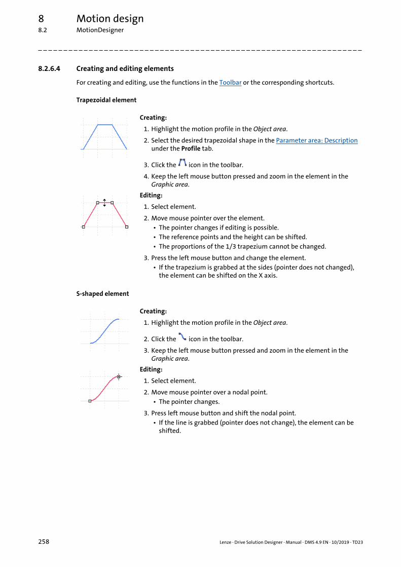
8 Motion design8.2 MotionDesigner
_ _ _ _ _ _ _ _ _ _ _ _ _ _ _ _ _ _ _ _ _ _ _ _ _ _ _ _ _ _ _ _ _ _ _ _ _ _ _ _ _ _ _ _ _ _ _ _ _ _ _ _ _ _ _ _ _ _ _ _ _ _ _ _
8.2.6.4 Creating and editing elements
For creating and editing, use the functions in the Toolbar or the corresponding shortcuts.
Trapezoidal element
S-shaped element
Creating:
1. Highlight the motion profile in the Object area.
2. Select the desired trapezoidal shape in the Parameter area: Description under the Profile tab.
3. Click the icon in the toolbar.
4. Keep the left mouse button pressed and zoom in the element in the Graphic area.
Editing:
1. Select element.
2. Move mouse pointer over the element.• The pointer changes if editing is possible.• The reference points and the height can be shifted.• The proportions of the 1/3 trapezium cannot be changed.
3. Press the left mouse button and change the element.• If the trapezium is grabbed at the sides (pointer does not changed),
the element can be shifted on the X axis.
Creating:
1. Highlight the motion profile in the Object area.
2. Click the icon in the toolbar.
3. Keep the left mouse button pressed and zoom in the element in the Graphic area.
Editing:
1. Select element.
2. Move mouse pointer over a nodal point.• The pointer changes.
3. Press left mouse button and shift the nodal point.• If the line is grabbed (pointer does not change), the element can be
shifted.
258 Lenze · Drive Solution Designer · Manual · DMS 4.9 EN · 10/2019 · TD23

8 Motion design8.2 MotionDesigner
_ _ _ _ _ _ _ _ _ _ _ _ _ _ _ _ _ _ _ _ _ _ _ _ _ _ _ _ _ _ _ _ _ _ _ _ _ _ _ _ _ _ _ _ _ _ _ _ _ _ _ _ _ _ _ _ _ _ _ _ _ _ _ _
Line element
Creating:
1. Highlight the motion profile or a parameter in the Object area.
2. Click the icon in the toolbar.
3. Keep the left mouse button pressed and zoom in the element in the Graphic area.
Editing:
1. Select element.
2. Move mouse pointer over a nodal point.• The pointer changes.
3. Press left mouse button and shift the nodal point.• If the line is grabbed (pointer does not change), the element can be
shifted.
Lenze · Drive Solution Designer · Manual · DMS 4.9 EN · 10/2019 · TD23 259

8 Motion design8.2 MotionDesigner
_ _ _ _ _ _ _ _ _ _ _ _ _ _ _ _ _ _ _ _ _ _ _ _ _ _ _ _ _ _ _ _ _ _ _ _ _ _ _ _ _ _ _ _ _ _ _ _ _ _ _ _ _ _ _ _ _ _ _ _ _ _ _ _
Shift elements automatically to the left
With one command, all elements on the drawing area can be quickly connected to a motion profile.Automatic connections are ignored and removed. The elements do not need to be selected for thisaction.
How to shift all elements automatically to the left:
1. Click the icon in the toolbar.• Each element is shifted towards its left adjacent element and connected to it if a
reasonable connection is possible.• The position of an element is defined by its center. An element is shifted if its center is
positioned to the right of its adjacent element.• Line elements and S-shaped elements are also shifted on the Y axis if a sensible
connection is possible.• The first element is not shifted.
260 Lenze · Drive Solution Designer · Manual · DMS 4.9 EN · 10/2019 · TD23

8 Motion design8.2 MotionDesigner
_ _ _ _ _ _ _ _ _ _ _ _ _ _ _ _ _ _ _ _ _ _ _ _ _ _ _ _ _ _ _ _ _ _ _ _ _ _ _ _ _ _ _ _ _ _ _ _ _ _ _ _ _ _ _ _ _ _ _ _ _ _ _ _
Combining elements
A self-created trapezoidal element consisting of S-shaped or line elements can be combined for easyhandling. At least tow and maximally five elements can be combined. A combined element is seenas one element in the MotionDesigner.
How to combine several elements:
1. Select each element using the mouse while keeping the Shift key pressed.
2. Click the icon in the toolbar.• The selected elements are combined.
Click the icon in the toolbar to undo the combination again.
Tip!
A predefined trapezoidal element in the MotionDesigner consists of combined elements.The combination can be undone as well.
Lenze · Drive Solution Designer · Manual · DMS 4.9 EN · 10/2019 · TD23 261

8 Motion design8.2 MotionDesigner
_ _ _ _ _ _ _ _ _ _ _ _ _ _ _ _ _ _ _ _ _ _ _ _ _ _ _ _ _ _ _ _ _ _ _ _ _ _ _ _ _ _ _ _ _ _ _ _ _ _ _ _ _ _ _ _ _ _ _ _ _ _ _ _
8.2.6.5 Error messages
Symbols signalise whether the motion or parameter profile are defective. A defective motion profilewill not be accepted in the dimensioning-dependent MotionDesigner.
Symbol Description
The motion profile contains incorrectly arranged elements.
The parameter profile contains incorrectly arranged elements.
The motion profile does not start or end with the same Y value.• Go tot the parameter area and correct the starting value of the first element or the final value of
the last element so that both values are identical.
Two elements overlap on the X axis. The last or first nodal point of both elements are not connected to each other.
• Shift or edit the elements so that they are connected. Use the flying restart function.• The flying restart function can be set in the ExtrasSettings menu in the "Motion" register.
( 43)
Two elements are positioned separately on the Y axis. The last or first nodal point of both elements are not connected to each other.
• Shift or edit the elements so that they are connected. Use the flying restart function.• The flying restart function can be set in the ExtrasSettings menu in the "Motion" register.
( 43)
The first element on the left starts on the time axis (X axis), not at 0.• Shift the element so that it starts at t = 0.
The parameter profile takes longer than the motion profile.• Limit the parameter profile to the length of the motion profile.
The control signals in the "Controller inhibit" or "Brake" parameter profile do not match the motion profile.
• An active controller inhibit or activated brake are only permitted in standstill phases.
262 Lenze · Drive Solution Designer · Manual · DMS 4.9 EN · 10/2019 · TD23

8 Motion design8.2 MotionDesigner
_ _ _ _ _ _ _ _ _ _ _ _ _ _ _ _ _ _ _ _ _ _ _ _ _ _ _ _ _ _ _ _ _ _ _ _ _ _ _ _ _ _ _ _ _ _ _ _ _ _ _ _ _ _ _ _ _ _ _ _ _ _ _ _
8.2.7 Parameter area: Description
In the parameter area, the values of a selected element of the motion profile or the parameterprofile are indicated.Graphically created elements can be optimised by entering the valuesnumerically. Elements can also be created by entering values numerically and attaching them to themotion profile. For the purpose of analysing, the values of the points of an imported profile areindicated in tabular form.
Tabs under which the parameter areas are edited."Profile" tab ( 264) "Line" tab: Motion profile ( 266) "Line" tab": Parameter profile ( 267) "S-edge" tab ( 269) "Imported profile" tab ( 270)
Call of the context-sensitive help in the parameter area
Attach an element with the specified values to the motion profile in the right Graphic area.• The button is only active if no element is selected in the Graphic area.
Change the highlighted element in the Graphic area according to the entered values.• For the selected element, the respective tab is always active.
Set the values in the input fields of the respective areas as a specification for the corresponding element.• The values do not need to be entered anew if you want to create several elements with the same values.• The values are specified until new values are set as specification.
Lenze · Drive Solution Designer · Manual · DMS 4.9 EN · 10/2019 · TD23 263

8 Motion design8.2 MotionDesigner
_ _ _ _ _ _ _ _ _ _ _ _ _ _ _ _ _ _ _ _ _ _ _ _ _ _ _ _ _ _ _ _ _ _ _ _ _ _ _ _ _ _ _ _ _ _ _ _ _ _ _ _ _ _ _ _ _ _ _ _ _ _ _ _
8.2.7.1 "Profile" tab
In this tab, you create or edit the trapezoidal elements. Select an already created element to edit it.Values are always entered positively.
Legend Description
Type
Trapezoidal element.
Trapezoidal element with creep speed.
Triangular element without constant travel.• The element has only one acceleration and deceleration phase.
Trapezoidal element.• The three phases acceleration, constant travel, acceleration take 1/3 each of the total
time of the element. These proportions cannot be changed.
S shape Trapezoidal acceleration and deceleration phase.• When the selection field is activated, the Jerk input field is shown.Non-linear motion profiles ( 283)
Base values
• Entry of the velocity or speed.• Grayed out input fields are deactivated. The values are calculated automatically.
Specification Specification – basic values ( 273)
Distance Distance / angle – basic values ( 274)
Angle
Time Time – basic values ( 274)
Speed Velocity / speed – basic values ( 274)
Speed
Time (right) Time (right) – basic values ( 274)
Velocity (right) Velocity (right) / speed (right) – basic values ( 275)
Speed (right)
Velocity limitSpeed limit
Acceleration
Specification Specification – acceleration ( 276)
Left Left – acceleration ( 276)
Centre Middle – acceleration ( 276)
Deceleration Right – acceleration ( 276)
264 Lenze · Drive Solution Designer · Manual · DMS 4.9 EN · 10/2019 · TD23

8 Motion design8.2 MotionDesigner
_ _ _ _ _ _ _ _ _ _ _ _ _ _ _ _ _ _ _ _ _ _ _ _ _ _ _ _ _ _ _ _ _ _ _ _ _ _ _ _ _ _ _ _ _ _ _ _ _ _ _ _ _ _ _ _ _ _ _ _ _ _ _ _
Jerk
• An S-shaped acceleration consists of three sections:• Showing the acceleration (rounding)• Linear acceleration• Hiding the acceleration (rounding)
• Values for rounding always apply to showing and hiding.• The input area is only displayed if the S shape selection field in the Type input area is
activated.
Specification Specification – jerk ( 277)
Left Left – jerk ( 277)
Centre Middle – jerk ( 277)
Right Right – jerk ( 277)
Buttons
Set as default Accept values in the areas Basic values, Acceleration and Jerk as specification.
Apply changes Change the highlighted element in the Graphic area according to the entered values.The button is only active if an element is selected in the Graphic area.
Attach element Attach an element with the specified values to the motion profile in the right Graphic area.• The button is only active if no element is selected in the Graphic area.
Legend Description
Lenze · Drive Solution Designer · Manual · DMS 4.9 EN · 10/2019 · TD23 265

8 Motion design8.2 MotionDesigner
_ _ _ _ _ _ _ _ _ _ _ _ _ _ _ _ _ _ _ _ _ _ _ _ _ _ _ _ _ _ _ _ _ _ _ _ _ _ _ _ _ _ _ _ _ _ _ _ _ _ _ _ _ _ _ _ _ _ _ _ _ _ _ _
8.2.7.2 "Line" tab: Motion profile
In this tab, you create or edit the line elements of a motion profile. Select an already created elementto edit it. Values are always entered positively.
Legend Description
Base values
• Entry of the speed.• Grayed out input fields are deactivated. The values are calculated automatically.
Specification Specification – basic values ( 273)
Distance Distance / angle – basic values ( 274)
Angle
Time Time – basic values ( 274)
Speed Velocity / final speed – basic values ( 275)
Final speed
Starting velocity Starting velocity / starting speed – basic values ( 275)
Starting speed
Acceleration Acceleration – basic values ( 275)
Buttons
Set as default Accept values in the Basic values area as specification.
Apply changes Change the highlighted element in the Graphic area according to the entered values.The button is only active if an element is selected in the Graphic area.
Attach element Attach an element with the specified values to the motion profile in the right Graphic area.• The button is only active if no element is selected in the Graphic area.
266 Lenze · Drive Solution Designer · Manual · DMS 4.9 EN · 10/2019 · TD23

8 Motion design8.2 MotionDesigner
_ _ _ _ _ _ _ _ _ _ _ _ _ _ _ _ _ _ _ _ _ _ _ _ _ _ _ _ _ _ _ _ _ _ _ _ _ _ _ _ _ _ _ _ _ _ _ _ _ _ _ _ _ _ _ _ _ _ _ _ _ _ _ _
8.2.7.3 "Line" tab": Parameter profile
In this tab, you create or edit the line elements of a parameter profile. Select an already createdelement to edit it. Values are always entered positively.
Legend Description
Type
<Parametername> <Parametername> – Type ( 273)
Specification Specification – Type ( 273) Object properties ( 247)
Base values
Time Time – basic values ( 274)
Left Left – basic values ( 275)
Right Right – basic values ( 276)
Controller lockedController released
Controller / brake – basic values ( 276)
Brake activatedBrake released
Buttons
Set as default Accept values in the areas Type and Basic values as specification.
Apply changes Change the highlighted element in the Graphic area according to the entered values.The button is only active if an element is selected in the Graphic area.
Attach element Attach an element with the specified values to the motion profile in the right Graphic area.• The button is only active if no element is selected in the Graphic area.
Lenze · Drive Solution Designer · Manual · DMS 4.9 EN · 10/2019 · TD23 267
8 Motion design8.2 MotionDesigner
_ _ _ _ _ _ _ _ _ _ _ _ _ _ _ _ _ _ _ _ _ _ _ _ _ _ _ _ _ _ _ _ _ _ _ _ _ _ _ _ _ _ _ _ _ _ _ _ _ _ _ _ _ _ _ _ _ _ _ _ _ _ _ _
Notes on dimensioning
• Standstill phase• The torque (holding torque) which is generated during the standstill phase does not have to
be absorbed by the motor. In the torque diagram of the motor it can be seen that the torque at standstill is set to zero. This torque can be taken over by the mechanical brake and is shown in the torque diagram of the brake. The corresponding diagrams can be selected in the result tree.
• Brake• For the activation of the brake, the Engagement time or Disengagement time is to be taken
into consideration.• Mechanical brake selection ( 360)
• Controller inhibit• In order to achieve an additional relief of the motor and the inverter, the setting of the
controller inhibit can be activated when the motion profile is entered. Generally, controller inhibit is also set if the mechanical brake is activated. If controller inhibit is set, the motor at standstill is no longer supplied with current and the effective current load is reduced.
• Mass of the payload, counterforce• Depending on the application, a payload or counterforce can be entered for each subprofile,
so that, for instance, empty movements or wind loads can be taken into consideration.
268 Lenze · Drive Solution Designer · Manual · DMS 4.9 EN · 10/2019 · TD23

8 Motion design8.2 MotionDesigner
_ _ _ _ _ _ _ _ _ _ _ _ _ _ _ _ _ _ _ _ _ _ _ _ _ _ _ _ _ _ _ _ _ _ _ _ _ _ _ _ _ _ _ _ _ _ _ _ _ _ _ _ _ _ _ _ _ _ _ _ _ _ _ _
8.2.7.4 "S-edge" tab
In this tab, you create or edit the S-shaped element of the motion profile. S-shaped elements canonly be used for accelerations and decelerations. Select an already created element to edit it. Valuesare always entered positively.
Legend Description
Base values
• Entry of the speed.• Grayed out input fields are deactivated. The values are calculated automatically.
Specification Specification – basic values ( 273)
Distance Distance / angle – basic values ( 274)
Angle
Time Time – basic values ( 274)
Speed Velocity / final speed – basic values ( 275)
Final speed
Starting velocity Starting velocity / starting speed – basic values ( 275)
Starting speed
Jerk
• An S-shaped acceleration consists of three sections:• Showing the acceleration (rounding)• Linear acceleration• Hiding the acceleration (rounding)
• Values for rounding always apply to showing and hiding.• Grayed out input fields are deactivated. The values are calculated automatically.
Specification Specification – jerk ( 277)
Jerk ratio Jerk ratio – jerk ( 277)
S-ramp time S-ramp time – jerk ( 277)
Jerk Jerk – jerk ( 278)
Max. acceleration Max. acceleration – jerk ( 278)
Buttons
Set as default Accept values in the areas Basic values and Jerk as specification.
Apply changes Change the highlighted element in the Graphic area according to the entered values.• The button is only active if an element is selected in the Graphic area.
Attach element Attach an element with the specified values to the motion profile in the right Graphic area.• The button is only active if no element is selected in the Graphic area.
Lenze · Drive Solution Designer · Manual · DMS 4.9 EN · 10/2019 · TD23 269

8 Motion design8.2 MotionDesigner
_ _ _ _ _ _ _ _ _ _ _ _ _ _ _ _ _ _ _ _ _ _ _ _ _ _ _ _ _ _ _ _ _ _ _ _ _ _ _ _ _ _ _ _ _ _ _ _ _ _ _ _ _ _ _ _ _ _ _ _ _ _ _ _
8.2.7.5 "Imported profile" tab
In this tab, you can check an imported motion profile or parameter profile and edit it slightly. Forthis purpose, the profile must be selected. It can be shifted at will and be scaled in seize. Thecombination cannot be undone. Further elements can be preceded or attached to the profile.
The imported dots of the motion profile and the parameters can be checked in the parameter area.Moreover, you can add more elements to the profile.
Legend Description
Tabular display of the imported dots and data.• If you select a line in the table, this imported value is displayed in the motion profile as a
dot.
Type
Points Number of imported dots.• Read only.
Show dots When the selection field is activated, it shows the dots on the motion profile in the Graphic area.
Update Update motion profile if data in the ASCII file has changed.• The Update button is only active if there is a linkage to the ASCII file.
• During import, a linking to the ASCII file is established. The linking is preserved even after the motion profile (Imp file) is saved. If the absolute data path changes, the linking gets lost.
• Importing profile data ( 252)
Base values
Grayed out input fields are deactivated. The values are calculated automatically.
Specification Specification – basic values ( 273)
Distance Distance / angle – basic values ( 274)
Angle
Time Time – basic values ( 274)
Speed Velocity / final speed – basic values ( 275)
Final speed
Starting velocity Starting velocity / starting speed – basic values ( 275)
Starting speed
Buttons
Apply changes Change the highlighted element in the Graphic area according to the entered values.The button is only active if an element is selected in the Graphic area.
Attach element Import an element from an ASCII file and attach it to the motion profile in the right Graphic area.
• The button is only active if no element is selected in the Graphic area.
270 Lenze · Drive Solution Designer · Manual · DMS 4.9 EN · 10/2019 · TD23
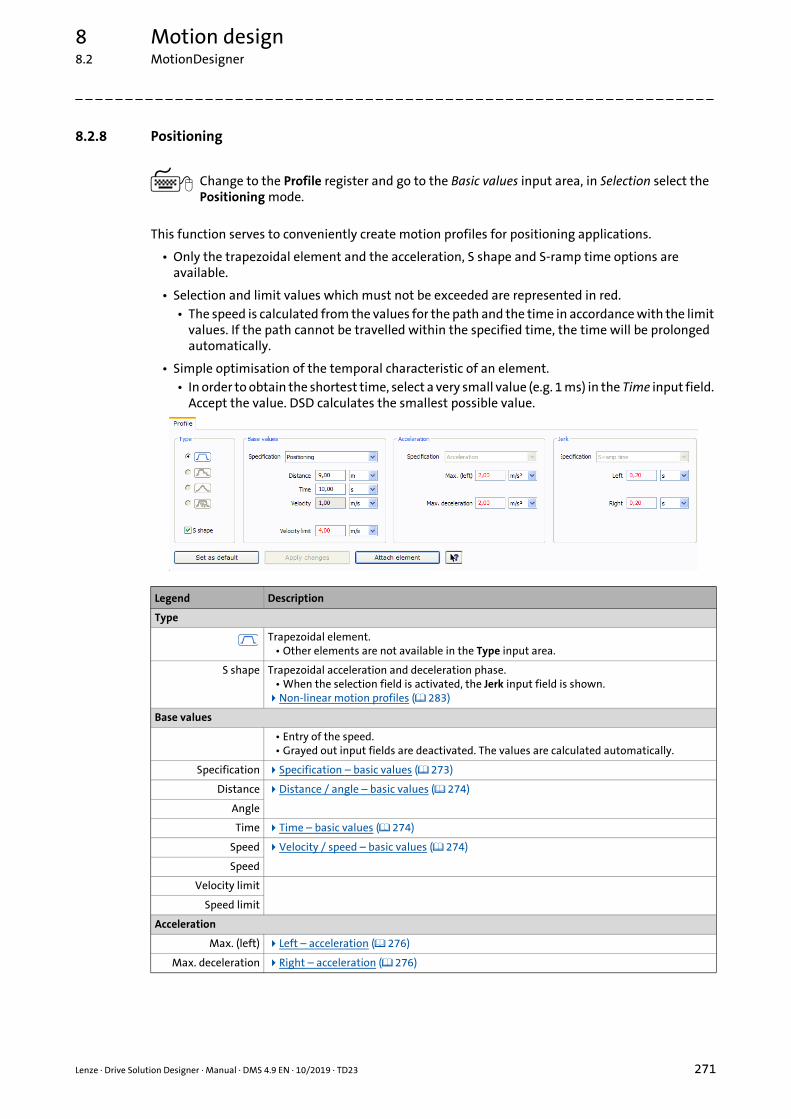
8 Motion design8.2 MotionDesigner
_ _ _ _ _ _ _ _ _ _ _ _ _ _ _ _ _ _ _ _ _ _ _ _ _ _ _ _ _ _ _ _ _ _ _ _ _ _ _ _ _ _ _ _ _ _ _ _ _ _ _ _ _ _ _ _ _ _ _ _ _ _ _ _
8.2.8 Positioning
Change to the Profile register and go to the Basic values input area, in Selection select the Positioning mode.
This function serves to conveniently create motion profiles for positioning applications.
• Only the trapezoidal element and the acceleration, S shape and S-ramp time options are available.
• Selection and limit values which must not be exceeded are represented in red.• The speed is calculated from the values for the path and the time in accordance with the limit
values. If the path cannot be travelled within the specified time, the time will be prolonged automatically.
• Simple optimisation of the temporal characteristic of an element.• In order to obtain the shortest time, select a very small value (e.g. 1 ms) in the Time input field.
Accept the value. DSD calculates the smallest possible value.
Legend Description
Type
Trapezoidal element.• Other elements are not available in the Type input area.
S shape Trapezoidal acceleration and deceleration phase.• When the selection field is activated, the Jerk input field is shown.Non-linear motion profiles ( 283)
Base values
• Entry of the speed.• Grayed out input fields are deactivated. The values are calculated automatically.
Specification Specification – basic values ( 273)
Distance Distance / angle – basic values ( 274)
Angle
Time Time – basic values ( 274)
Speed Velocity / speed – basic values ( 274)
Speed
Velocity limit
Speed limit
Acceleration
Max. (left) Left – acceleration ( 276)
Max. deceleration Right – acceleration ( 276)
Lenze · Drive Solution Designer · Manual · DMS 4.9 EN · 10/2019 · TD23 271

8 Motion design8.2 MotionDesigner
_ _ _ _ _ _ _ _ _ _ _ _ _ _ _ _ _ _ _ _ _ _ _ _ _ _ _ _ _ _ _ _ _ _ _ _ _ _ _ _ _ _ _ _ _ _ _ _ _ _ _ _ _ _ _ _ _ _ _ _ _ _ _ _
Jerk
• An S-shaped acceleration consists of three sections:• Showing the acceleration (rounding)• Linear acceleration• Hiding the acceleration (rounding)
• Values for rounding always apply to showing and hiding.• The input area is only displayed if the S shape selection field in the Type input area is
activated.
Left Left – jerk ( 277)
Right Right – jerk ( 277)
Buttons
Set as default Accept values in the areas Basic values, Acceleration and Jerk as specification.
Apply changes Change the highlighted element in the Graphic area according to the entered values.The button is only active if an element is selected in the Graphic area.
Attach element Attach an element with the specified values to the motion profile in the right Graphic area.• The button is only active if no element is selected in the Graphic area.
Legend Description
272 Lenze · Drive Solution Designer · Manual · DMS 4.9 EN · 10/2019 · TD23

8 Motion design8.2 MotionDesigner
_ _ _ _ _ _ _ _ _ _ _ _ _ _ _ _ _ _ _ _ _ _ _ _ _ _ _ _ _ _ _ _ _ _ _ _ _ _ _ _ _ _ _ _ _ _ _ _ _ _ _ _ _ _ _ _ _ _ _ _ _ _ _ _
8.2.9 Parameter area: Data for the entry
The following chapters describe data that can be entered or selected in the parameter area.
8.2.9.1 <Parametername> – Type
8.2.9.2 Specification – Type
8.2.9.3 Specification – basic values
Parameter Description
<Parametername> Name of the parameter that is selected in the object area.• Read only."Line" tab": Parameter profile ( 267) Object properties ( 247)
Parameter Description
Specification Standard value with which the parameter is automatically created.• The entry of more line elements creates an individual parameter profile.• The "brake" and "controller inhibit" parameters do not have a default value as these
control signals can only have the states 1 or 0."Line" tab": Parameter profile ( 267) Object properties ( 247)
Parameter Description
Specification Selection of the quantities to be entered.• Translatory motion profile:
• Velocity / time• Distance/time• Distance / velocity
• Rotary motion profile:• Speed / time• Angle / time• Angle / velocity
Use of the parameter:"Profile" tab ( 264) "Line" tab: Motion profile ( 266) "S-edge" tab ( 269) "Imported profile" tab ( 270)
• PositioningUse of the parameter:Positioning ( 271)
Lenze · Drive Solution Designer · Manual · DMS 4.9 EN · 10/2019 · TD23 273

8 Motion design8.2 MotionDesigner
_ _ _ _ _ _ _ _ _ _ _ _ _ _ _ _ _ _ _ _ _ _ _ _ _ _ _ _ _ _ _ _ _ _ _ _ _ _ _ _ _ _ _ _ _ _ _ _ _ _ _ _ _ _ _ _ _ _ _ _ _ _ _ _
8.2.9.4 Distance / angle – basic values
8.2.9.5 Time – basic values
8.2.9.6 Velocity / speed – basic values
8.2.9.7 Time (right) – basic values
Parameter Description
DistanceAngle
• Translatory motion profile:• Covered distance when the operation of the element is completed.
• Rotary motion profile:• Covered angle of rotation when the operation of the element is completed.
Use of the parameter:"Profile" tab ( 264) "Line" tab: Motion profile ( 266) "S-edge" tab ( 269) "Imported profile" tab ( 270)
Parameter Description
Time Time required for the operation of the element.Use of the parameter:"Profile" tab ( 264) "Line" tab: Motion profile ( 266) "Line" tab": Parameter profile ( 267) "S-edge" tab ( 269) "Imported profile" tab ( 270)
Parameter Description
SpeedSpeed
• Translatory motion profile:• Max. velocity when the operation of the element is completed.
• Rotary motion profile:• Max. speed when the operation of the element is completed.
Use of the parameter:"Profile" tab ( 264)
Parameter Description
Time (right) Duration of the constant travel after the second acceleration or deceleration.• The input field is only shown in case of an element for creep speed.
Use of the parameter:"Profile" tab ( 264)
274 Lenze · Drive Solution Designer · Manual · DMS 4.9 EN · 10/2019 · TD23

8 Motion design8.2 MotionDesigner
_ _ _ _ _ _ _ _ _ _ _ _ _ _ _ _ _ _ _ _ _ _ _ _ _ _ _ _ _ _ _ _ _ _ _ _ _ _ _ _ _ _ _ _ _ _ _ _ _ _ _ _ _ _ _ _ _ _ _ _ _ _ _ _
8.2.9.8 Velocity (right) / speed (right) – basic values
8.2.9.9 Velocity / final speed – basic values
8.2.9.10 Starting velocity / starting speed – basic values
8.2.9.11 Acceleration – basic values
8.2.9.12 Left – basic values
Parameter Description
Velocity (right)Speed (right)
• Translatory motion profile:• Velocity after the second acceleration or deceleration.
• Rotary motion profile:• Speed after the second acceleration or deceleration.
• The input field is only shown in case of an element for creep speed.Use of the parameter:"Profile" tab ( 264)
Parameter Description
SpeedFinal speed
• Translatory motion profile:• Velocity when the operation of the element is completed.
• Rotary motion profile:• Speed when the operation of the element is completed.
Use of the parameter:"Line" tab: Motion profile ( 266) "S-edge" tab ( 269) "Imported profile" tab ( 270)
Parameter Description
Starting velocityStarting speed
• Translatory motion profile:• Velocity when the operation of the element starts.
• Rotary motion profile:• Speed when the operation of the element starts.
• The input field is only shown if an element is selected."Line" tab: Motion profile ( 266) "S-edge" tab ( 269) "Imported profile" tab ( 270)
Parameter Description
Acceleration Acceleration or deceleration from start to end of the element operation."Line" tab: Motion profile ( 266)
Parameter Description
Left Value when the operation of the element starts."Line" tab": Parameter profile ( 267)
Lenze · Drive Solution Designer · Manual · DMS 4.9 EN · 10/2019 · TD23 275

8 Motion design8.2 MotionDesigner
_ _ _ _ _ _ _ _ _ _ _ _ _ _ _ _ _ _ _ _ _ _ _ _ _ _ _ _ _ _ _ _ _ _ _ _ _ _ _ _ _ _ _ _ _ _ _ _ _ _ _ _ _ _ _ _ _ _ _ _ _ _ _ _
8.2.9.13 Right – basic values
8.2.9.14 Controller / brake – basic values
8.2.9.15 Specification – acceleration
8.2.9.16 Left – acceleration
8.2.9.17 Middle – acceleration
8.2.9.18 Right – acceleration
Parameter Description
Right Value when the operation of the element is completed."Line" tab": Parameter profile ( 267)
Parameter Description
Controller lockedController released
Control signal for the inverter."Line" tab": Parameter profile ( 267)
Brake activatedBrake released
Control signal for the electromechanical brake."Line" tab": Parameter profile ( 267)
Parameter Description
Specification The following quantities can be selected:• Max. acceleration.• Acceleration time:
• Elapsed time until the application has accelerated to setpoint speed.• Acceleration distance:
• Covered distance until the application has accelerated to setpoint speed.Use of the parameter:"Profile" tab ( 264)
Parameter Description
Left Acceleration from standstill to setpoint speed.Use of the parameter:"Profile" tab ( 264)
Parameter Description
Centre More acceleration or deceleration from a certain speed.• The input field is only shown in case of an element for creep speed.
Use of the parameter:"Profile" tab ( 264)
Parameter Description
Right Deceleration to standstill.Use of the parameter:"Profile" tab ( 264)
276 Lenze · Drive Solution Designer · Manual · DMS 4.9 EN · 10/2019 · TD23

8 Motion design8.2 MotionDesigner
_ _ _ _ _ _ _ _ _ _ _ _ _ _ _ _ _ _ _ _ _ _ _ _ _ _ _ _ _ _ _ _ _ _ _ _ _ _ _ _ _ _ _ _ _ _ _ _ _ _ _ _ _ _ _ _ _ _ _ _ _ _ _ _
8.2.9.19 Specification – jerk
8.2.9.20 Left – jerk
8.2.9.21 Middle – jerk
8.2.9.22 Right – jerk
8.2.9.23 Jerk ratio – jerk
8.2.9.24 S-ramp time – jerk
Parameter Description
Specification The following quantities can be selected:• Jerk ratio:
• Percentage of the three sections "Show", "Linear acceleration" and "Hide" in the entire element.
• S-ramp time:• Duration of the show and hide phase.
• Jerk:• Acceleration during the show and hide phase.
• Max. acceleration• Acceleration or deceleration from start to end of the element operation.• The selection is only shown for an S-shaped element.
"Profile" tab ( 264) "S-edge" tab ( 269)
Parameter Description
Left Jerk for the acceleration from standstill to setpoint speed."Profile" tab ( 264)
Parameter Description
Centre Jerk for further acceleration or deceleration.• The input field is only shown in case of an element for creep speed."Profile" tab ( 264)
Parameter Description
Right Jerk for the deceleration to standstill."Profile" tab ( 264)
Parameter Description
Jerk ratio Percentage of the three sections "Show", "Linear acceleration" and "Hide" in the entire element."S-edge" tab ( 269)
Parameter Description
S-ramp time Duration of the show and hide phase."S-edge" tab ( 269)
Lenze · Drive Solution Designer · Manual · DMS 4.9 EN · 10/2019 · TD23 277

8 Motion design8.2 MotionDesigner
_ _ _ _ _ _ _ _ _ _ _ _ _ _ _ _ _ _ _ _ _ _ _ _ _ _ _ _ _ _ _ _ _ _ _ _ _ _ _ _ _ _ _ _ _ _ _ _ _ _ _ _ _ _ _ _ _ _ _ _ _ _ _ _
8.2.9.25 Jerk – jerk
8.2.9.26 Max. acceleration – jerk
Parameter Description
Jerk Acceleration during the show and hide phase."S-edge" tab ( 269)
Parameter Description
Max. acceleration Acceleration or deceleration from start to end of the element operation."S-edge" tab ( 269)
278 Lenze · Drive Solution Designer · Manual · DMS 4.9 EN · 10/2019 · TD23

8 Motion design8.2 MotionDesigner
_ _ _ _ _ _ _ _ _ _ _ _ _ _ _ _ _ _ _ _ _ _ _ _ _ _ _ _ _ _ _ _ _ _ _ _ _ _ _ _ _ _ _ _ _ _ _ _ _ _ _ _ _ _ _ _ _ _ _ _ _ _ _ _
8.2.10 Motion profile: application instructions
8.2.10.1 Minimum acceleration and deceleration times
For increasingly lower acceleration and deceleration times the requirement with regard to thedynamic torque increases proportionally to the acceleration and reciprocal to the acceleration ordeceleration time:
• Thus a greater drive is required, which, however, has to accelerate itself as well.• For greater motors the accelerating power is smaller than for smaller motors. It is therefore
possible that a motor selected later on can no longer meet the specifications.• These interdependencies are automatically taken into consideration in the DSD, so that a
warning is output if limit values are exceeded.
[8-1] Acceleration capability as a function of the frame size
tr = acceleration timetf = deceleration timeMdyn = dynamic torque
= angular accelerationMN = rated torqueStandard asynchronous motor Asynchronous servo motor Synchronous servo motor
Mdyn a or Mdyn
Mdyn1tr---- or Mdyn
1tf----
�
�
�
a, �
motorsize
~ MN
Lenze · Drive Solution Designer · Manual · DMS 4.9 EN · 10/2019 · TD23 279

8 Motion design8.2 MotionDesigner
_ _ _ _ _ _ _ _ _ _ _ _ _ _ _ _ _ _ _ _ _ _ _ _ _ _ _ _ _ _ _ _ _ _ _ _ _ _ _ _ _ _ _ _ _ _ _ _ _ _ _ _ _ _ _ _ _ _ _ _ _ _ _ _
• If the values for acceleration and deceleration times are extremely low, the rise times and settling times of the drive become already noticeable and superimpose the desired speed profile. Although the acceleration and deceleration times can be physically provided by the drive, they are not feasible in a control-oriented manner, so that delays result.
[8-2] Drive behaviour for highly dynamic motion profiles
• These effects can occur in the case of highly dynamic clocked drives, like for example cam applications, cross cutters, handling devices, robots, packaging machines.
tacc,set Acceleration time - setpoint
tacc,act Acceleration time - actual value
tdec,set Deceleration time - setpoint
tdec,act Deceleration time - actual value
n, v
ttacc,set
tacc,act
tdec,set
tdec,act
280 Lenze · Drive Solution Designer · Manual · DMS 4.9 EN · 10/2019 · TD23

8 Motion design8.2 MotionDesigner
_ _ _ _ _ _ _ _ _ _ _ _ _ _ _ _ _ _ _ _ _ _ _ _ _ _ _ _ _ _ _ _ _ _ _ _ _ _ _ _ _ _ _ _ _ _ _ _ _ _ _ _ _ _ _ _ _ _ _ _ _ _ _ _
• The table below provides guide values for minimum acceleration and deceleration times. If the values fall below these values, the behaviour of the control system of the drive must be checked in addition.
VFC plus SLVC SC
tacc,set/tdec,set tacc,set/tdec,set tacc,set/tdec,set
Servo inverter
i700 servo inverter < 100 ms – < 50 ms
Servo Drives 9400 HighLine
Inverter Drives 8400 TopLine
Frequency inverter
Inverter Drives 8400 BaseLine < 100 ms < 500 ms < 50 ms
Inverter Drives 8400 StateLine
Inverter Drives 8400 HighLine
Inverter Drives 8400 TopLine
Decentralised inverters
Inverter Drives 8400 motec < 100 ms < 500 ms –
Inverter Drives 8400 protec < 100 ms < 500 ms < 50 ms
The following conditions must be complied with:• tr,set > tdyn,min• tf,set > tdyn,min
VFC plus Voltage frequency control
SLVC Sensorless vector control
SC Servo control
tacc,set Acceleration time - setpoint
tacc,act Acceleration time - actual value
tdec,set Deceleration time - setpoint
tdec,act Deceleration time - actual value
tdyn,min Dynamic acceleration and deceleration time that the control system of the inverter is able to realise at least
Note!
Without a specific feedforward control of the required acceleration torque within the inverter, these control-related deceleration times are to be taken into consideration.
If the actual times are lower than the deceleration times, a control-related system consideration on the basis of empirical checks (e. g. on a test configuration) or by an appropriate simulation has to be carried out in addition to the drive dimensioning with the DSD.
Lenze · Drive Solution Designer · Manual · DMS 4.9 EN · 10/2019 · TD23 281

8 Motion design8.2 MotionDesigner
_ _ _ _ _ _ _ _ _ _ _ _ _ _ _ _ _ _ _ _ _ _ _ _ _ _ _ _ _ _ _ _ _ _ _ _ _ _ _ _ _ _ _ _ _ _ _ _ _ _ _ _ _ _ _ _ _ _ _ _ _ _ _ _
8.2.10.2 Linear motion profiles
Linear motion profiles have no jerk limitation, and the maximum values of torque and speed arereached simultaneously.
[8-3] Linear motion profile
[8-4] Speed/torque/speed characteristic of the motor with a linear motion profile
AccelerationVelocity
a [m/s ]
t [s]
2
0
v [m/s]
t [s]0
� �
282 Lenze · Drive Solution Designer · Manual · DMS 4.9 EN · 10/2019 · TD23

8 Motion design8.2 MotionDesigner
_ _ _ _ _ _ _ _ _ _ _ _ _ _ _ _ _ _ _ _ _ _ _ _ _ _ _ _ _ _ _ _ _ _ _ _ _ _ _ _ _ _ _ _ _ _ _ _ _ _ _ _ _ _ _ _ _ _ _ _ _ _ _ _
8.2.10.3 Non-linear motion profiles
For motion applications (highly dynamic motion drives) in the fields of robotics, mounting,handling, apart from linear profiles there are further motion profiles with a jerk limitation:
• S-shaped motion profiles
• sin²-shaped motion profiles
• CAM curve profiles• CAM curve profiles can be created with the »CAM Designer« in the »Engineer«. Data can be
transferred to the DSD using the exchange format TXT or DPR.
In comparison to a linear motion profile, a motion profile with jerk limitation produces a greatertorque acceleration and thus a higher dynamic torque. Since this only occurs in the medium speedrange and the motor can usually be actuated at higher speeds than those for linear motion profiles,the additional torque requirement is compensated by the greater gearbox ratio.
Highly dynamic motions result in an increasingly high load of the gearbox. The S-ramp timesdetermined in DSD must be complied with for the gearbox not to be overloaded.
The following table shows advantages of a motion profile with jerk limitation:
Advantages for the application Advantages for the motor/inverter
• Movement is effected with jerk limitation (s-shaped motion profile).
• Movement is effected with a continuous jerk pattern (sinusoidal2 motion profile, some CAM curve profiles).
• Mechanical resonances are less active.• Mechanics are prevented from damage.
• The motor is clearly better utilised in the set of characteristic curves (maximum values of torque and speed do not arise at the same time, thus higher motor speeds and greater transmission ratios are possible).
• Load-matching factor kj can be reduced.• More stable control• Higher dynamic performance
Lenze · Drive Solution Designer · Manual · DMS 4.9 EN · 10/2019 · TD23 283

8 Motion design8.2 MotionDesigner
_ _ _ _ _ _ _ _ _ _ _ _ _ _ _ _ _ _ _ _ _ _ _ _ _ _ _ _ _ _ _ _ _ _ _ _ _ _ _ _ _ _ _ _ _ _ _ _ _ _ _ _ _ _ _ _ _ _ _ _ _ _ _ _
S-shaped motion profiles
In the case of the S-shaped motion profile the acceleration is shown and hidden linearly, by whichthe jerk is limited. Here the maximum values of torque and speed are not reached simultaneously.Like this, the motor can be better utilised in the set of characteristic curves for higher speeds.
• The max. attainable speed is higher than for the linear profile.
• Compared to the linear profile the Base process power is greater.
• Since the acceleration is shown and hidden linearly, the maximum acceleration is greater than in the case of the linear motion profile.
[8-5] S-shaped motion profile
[8-6] Torque/speed characteristic of the motor with S-shaped motion profile
AccelerationVelocity
a [m/s ]
t [s]
2
0
v [m/s]
t [s]0
� �
284 Lenze · Drive Solution Designer · Manual · DMS 4.9 EN · 10/2019 · TD23

8 Motion design8.2 MotionDesigner
_ _ _ _ _ _ _ _ _ _ _ _ _ _ _ _ _ _ _ _ _ _ _ _ _ _ _ _ _ _ _ _ _ _ _ _ _ _ _ _ _ _ _ _ _ _ _ _ _ _ _ _ _ _ _ _ _ _ _ _ _ _ _ _
sin²-shaped motion profiles
In the case of the sin2-shaped motion profile, acceleration is effected in a sinusoidal manner. Thejerk is also sinusoidal, i. e. continuously. The maximum values of torque and speed are not reachedsimultaneously; like this, the motor can be better utilised at higher speeds.
• The maximum speed that can be reached is higher than in the cases of the linear and S-shaped motion profiles.
• In comparison to the S-shaped motion profile, the Base process power is greater.
• Since the acceleration is effected in a sinusoidal manner, the maximum acceleration is greater than in the case of the linear motion profile (57 % of the acceleration of the linear motion profile).
• sin2-shaped motion profiles in the torque-speed diagram of the motor are represented in a circle of ellipsoidal manner.
[8-7] Sin2-shaped motion profile
[8-8] Speed-torque characteristics of the motor with Sin2-shaped motion profile
AccelerationVelocity
a [m/s ]
t [s]
2
0
v [m/s]
t [s]0
� �
Lenze · Drive Solution Designer · Manual · DMS 4.9 EN · 10/2019 · TD23 285

8 Motion design8.3 Predefined motion profile according to operating mode
_ _ _ _ _ _ _ _ _ _ _ _ _ _ _ _ _ _ _ _ _ _ _ _ _ _ _ _ _ _ _ _ _ _ _ _ _ _ _ _ _ _ _ _ _ _ _ _ _ _ _ _ _ _ _ _ _ _ _ _ _ _ _ _
8.3 Predefined motion profile according to operating mode
For the selection of the motor, the operating mode is important. A motor, for instance, heats up lesswhen loaded for a short time than when loaded continuously, and therefore it can be selectedsmaller.
• It is advisable to use the motion profile for steady-state operation. Acceleration processes can be taken into consideration. The motion profile is repeated in a cyclic manner.
• The predefined motion profiles are based on the operating modes in accordance with VDE 0530 or IEC 34-1.
• The DSD offers the selection of the operating modes S1, S2, S3 and S6.
• Operation of a motor in modes other than S1 may be run at a higher power level.
8.3.1 S1, continuous operation
Operation with a constant load that is available until the machine reaches the thermal steady state.
[8-9] Motion profile for operating mode S1
tacc tdec
t
Description
t Cycle time, corresponds to the duration of the load phase.
tacc Acceleration time required by the drive until the constant load condition is reached.
tdec Deceleration time required by the drive until standstill.
286 Lenze · Drive Solution Designer · Manual · DMS 4.9 EN · 10/2019 · TD23

8 Motion design8.3 Predefined motion profile according to operating mode
_ _ _ _ _ _ _ _ _ _ _ _ _ _ _ _ _ _ _ _ _ _ _ _ _ _ _ _ _ _ _ _ _ _ _ _ _ _ _ _ _ _ _ _ _ _ _ _ _ _ _ _ _ _ _ _ _ _ _ _ _ _ _ _
8.3.2 S2, short-term operation
The operating time with constant load does not suffice to reach the thermal steady state. Duringthe break that follows, the motor can cool down to the initial temperature.
[8-10] Motion profile for operating mode S2
t
BRK = 1CINH = 1
tacc tdec
Description
t Cycle time, corresponds to the duration of the load phase.
tacc Acceleration time required by the drive until the constant load condition is reached.
tdec Deceleration time required by the drive until standstill.
BRK Brake, BRK = 1: brake active
CINH Controller inhibit, CINH = 1: controller inhibit active
Lenze · Drive Solution Designer · Manual · DMS 4.9 EN · 10/2019 · TD23 287

8 Motion design8.3 Predefined motion profile according to operating mode
_ _ _ _ _ _ _ _ _ _ _ _ _ _ _ _ _ _ _ _ _ _ _ _ _ _ _ _ _ _ _ _ _ _ _ _ _ _ _ _ _ _ _ _ _ _ _ _ _ _ _ _ _ _ _ _ _ _ _ _ _ _ _ _
8.3.3 Intermittent operation S3, S4, S5
The intermittent operation consists of a sequence of identical cycles, each of which including anoperating time with constant load and a downtime.
Starting and braking times as well as inertias are characteristics of the respective operating mode:
• S3: The starting current is irrelevant for the motor heating.
• S4: The starting process is thermally relevant in addition.
• S5: The brake reaction and the starting performance are taken into consideration.
[8-11] Motion profile for operating mode S3
t
BRK = 1CINH = 1
tacc tdec
Description
t Cycle time, corresponds to the duration of the load phase.
tacc Acceleration time required by the drive until the constant load condition is reached.
tdec Deceleration time required by the drive until standstill.
BRK Brake, BRK = 1: brake active
CINH Controller inhibit, CINH = 1: controller inhibit active
288 Lenze · Drive Solution Designer · Manual · DMS 4.9 EN · 10/2019 · TD23

8 Motion design8.3 Predefined motion profile according to operating mode
_ _ _ _ _ _ _ _ _ _ _ _ _ _ _ _ _ _ _ _ _ _ _ _ _ _ _ _ _ _ _ _ _ _ _ _ _ _ _ _ _ _ _ _ _ _ _ _ _ _ _ _ _ _ _ _ _ _ _ _ _ _ _ _
8.3.4 Intermittent load S6, S7
Operation composed of a sequence of identical cycles each of which including an operating timewith constant load and an idle time. There is no idle time.
[8-12] Motion profile for operating mode S6
ED
t t
tacc tdec
Description
t Cycle time, complies with the load period.
tacc Acceleration time required by the drive until the constant load condition is reached.
tdec Deceleration time required by the drive until standstill.
OT Relative operating time• The relative operating time is the ratio of the load period to the cycle time.
Lenze · Drive Solution Designer · Manual · DMS 4.9 EN · 10/2019 · TD23 289

8 Motion design8.3 Predefined motion profile according to operating mode
_ _ _ _ _ _ _ _ _ _ _ _ _ _ _ _ _ _ _ _ _ _ _ _ _ _ _ _ _ _ _ _ _ _ _ _ _ _ _ _ _ _ _ _ _ _ _ _ _ _ _ _ _ _ _ _ _ _ _ _ _ _ _ _
8.3.5 Data for the entry
8.3.5.1 Max. velocity
See also: Chain conveyor ( 133) Speed ( 138)
Roller conveyor ( 139) Speed ( 145)
Belt conveyor, unit load ( 146) Speed ( 150)
Belt conveyor, bulk material ( 151) Speed ( 157)
Synchronous drive - single roll ( 158) Speed ( 163)
Synchronous drive of squeegees ( 164) Speed ( 170)
8.3.5.2 Speed
8.3.5.3 Variable payload mass
See also: Rack drive ( 94) Mass of the payload ( 99)
Wheel drive ( 106) Mass of the payload ( 111)
8.3.5.4 Counter-torque
Parameter Description
vmax Max. velocity of the application.
Parameter Description
nApp Speed of application.• Speed required at the output shaft.• Please note: The speed of the application, not the rated speed of the motor is meant!
Parameter Description
mvar,L Changeable mass of the payload.• For the calculation in the DSD it is assumed that the payload is distributed evenly.
Parameter Description
Mvs Counter-torque that the drive must exert.• Required torque at the output shaft.
290 Lenze · Drive Solution Designer · Manual · DMS 4.9 EN · 10/2019 · TD23

8 Motion design8.3 Predefined motion profile according to operating mode
_ _ _ _ _ _ _ _ _ _ _ _ _ _ _ _ _ _ _ _ _ _ _ _ _ _ _ _ _ _ _ _ _ _ _ _ _ _ _ _ _ _ _ _ _ _ _ _ _ _ _ _ _ _ _ _ _ _ _ _ _ _ _ _
8.3.5.5 Variable force associated with the application
See also: Belt drive, rotating ( 72) Tensile force at the slide (counterforce) ( 82)
Omega belt drive ( 83) Counterforce ( 93)
Rack drive ( 94) Counterforce ( 99)
Spindle drive ( 100) Counterforce ( 105)
Wheel drive ( 106) Counterforce ( 112)
8.3.5.6 Basic setting of motion profile
8.3.5.7 Relative operating time
8.3.5.8 Operating time
8.3.5.9 Brake at standstill
Parameter Description
Fvar,App Required force of the application, changeable.
Parameter Description
Use The values of the basic settings are marked grey and cannot be altered.
Change The values of the basic setting can be altered.
Parameter Description
OT The relative operating time is the ratio of the load period to the cycle time.• The designation of the operating mode is supplemented by the relative operating time, e. g.
"S3-25 %".
Parameter Description
ton The operating time corresponds to the load time of the drive.• The designation of the operating mode is supplemented by the operating time, e. g. "S2-
60 min".
Parameter Description
Active • Yes• The brake is active at standstill. If the brake is activated, the motor does not have to provide
a torque.• No
• The brake is not active at standstill.
Lenze · Drive Solution Designer · Manual · DMS 4.9 EN · 10/2019 · TD23 291

8 Motion design8.3 Predefined motion profile according to operating mode
_ _ _ _ _ _ _ _ _ _ _ _ _ _ _ _ _ _ _ _ _ _ _ _ _ _ _ _ _ _ _ _ _ _ _ _ _ _ _ _ _ _ _ _ _ _ _ _ _ _ _ _ _ _ _ _ _ _ _ _ _ _ _ _
8.3.5.10 Controller inhibit at standstill
8.3.5.11 Acceleration time
8.3.5.12 Deceleration time
8.3.5.13 Cycle time
8.3.5.14 Direction of movement
Parameter Description
Active • Yes• The controller inhibit of the inverter is set. The thermal load of the inverter and motor is
reduced by this.• No
• The controller inhibit of the inverter is not set.
Parameter Description
tacc Acceleration time required by the drive until the constant load condition is reached.
Parameter Description
tdec Deceleration time required by the drive until standstill.
Parameter Description
t The cycle time corresponds to the duration of the load phase.
Parameter Description
Forward/back / Up/down
• Positive• The cycle is only positive. Accordingly, the drive only moves in positive direction.
• Both• The cycle alternates between positive and negative. Accordingly, the drive first moves to
the positive, then to the negative direction.
292 Lenze · Drive Solution Designer · Manual · DMS 4.9 EN · 10/2019 · TD23

9 Mains and environment9.1 Electrical supply system
_ _ _ _ _ _ _ _ _ _ _ _ _ _ _ _ _ _ _ _ _ _ _ _ _ _ _ _ _ _ _ _ _ _ _ _ _ _ _ _ _ _ _ _ _ _ _ _ _ _ _ _ _ _ _ _ _ _ _ _ _ _ _ _
9 Mains and environment
Mains voltage, power system, and ambient conditions are decisive for the operation of the drivesystem.
9.1 Electrical supply system
Select the supply system the drive system is to be connected to. For an inverter with DC supply,select the supply system of the energy supplier.
9.1.1 Power system
In the following the power systems which can be selected in the DSD and which are in useworldwide are described in detail.
Earthed power systems
TT and TN systems are power systems with an earthed neutral. They are used in most countries. Insome countries, power systems with earthed phase conductors are also used.
Supply system Mains frequency Power system Note
1AC 230 V 50 Hz TN/TT systemIT mains
• Europe, Asia, Africa and Australia have a mains frequency of 50 Hz.
• North America and parts of South America have a 60-Hz mains frequency.
• Select a rated mains voltage of 400 V for 380-V systems.
3AC 230 V
3AC 400 V
3AC 415 V
1AC 120 V 60 Hz
1AC 240 V
3AC 240 V
3AC 480 V
Earthed power systems Unearthed power systems
TT supply (with earthed star point) TN supply (with earthed star point) IT supply (with floating star point)
L1
L2
L3
N
PE
L1
L2
L3
N
PE
L1
L2
L3
PE
Lenze · Drive Solution Designer · Manual · DMS 4.9 EN · 10/2019 · TD23 293

9 Mains and environment9.2 Ambient conditions
_ _ _ _ _ _ _ _ _ _ _ _ _ _ _ _ _ _ _ _ _ _ _ _ _ _ _ _ _ _ _ _ _ _ _ _ _ _ _ _ _ _ _ _ _ _ _ _ _ _ _ _ _ _ _ _ _ _ _ _ _ _ _ _
Unearthed power systems
IT systems are power systems with an isolated neutral. They are used in the following countries andindustry sectors:
• In the public supply system in France and Belgium
• Chemical industry
• Mining
• Island power supplies (own generator)
• Hospitals
• Ship's mains
• Crane, conveyor, and hoist systems
• Paper and pulp industry
Advantages of the IT systems are the high fire and operator safety. Furthermore there is nodisconnection during the first earth fault.
9.2 Ambient conditions
9.2.1 Max. ambient temperature, motor/gearbox
The permissible load capacity depends on the ambient temperature. The load capacity also dependson whether a geared motor or a motor without a gearbox is used.
Tip!
If a geared motor is used, the derating starts from a temperature of 30 °C, in the case of amotor without a gearbox it starts from 40 °C.
Depending on the site altitude, the following correction values k result for geared motors:
opr k
1000 m 2000 m 3000 m 4000 m
20 °C 1.15 1.04 0.92 0.81
30 °C 1 0.9 0.8 0.70
40 °C 0.8 0.72 0.64 0.56
50 °C 0.6 0.54 0.48 0.42
60 °C 0.4 0.36 0.32 0.28
294 Lenze · Drive Solution Designer · Manual · DMS 4.9 EN · 10/2019 · TD23

9 Mains and environment9.2 Ambient conditions
_ _ _ _ _ _ _ _ _ _ _ _ _ _ _ _ _ _ _ _ _ _ _ _ _ _ _ _ _ _ _ _ _ _ _ _ _ _ _ _ _ _ _ _ _ _ _ _ _ _ _ _ _ _ _ _ _ _ _ _ _ _ _ _
For motors without a gearbox the following correction values k result:
9.2.2 Max. ambient temperature, inverter
DSD considers the drive-specific reduction factors and an ambient temperature range of 0 ... 60 °C.
• The ranges from -20 ... 0 °C have to be checked manually.
• In a temperature range of 0 ... 40 °C, operation of the components can be carried out without a power derating.
• For inverters the derating factor is stored in the DSD device-specifically.
opr k
0 ... 40 °C 1
45 °C 0.95
50 °C 0.9
55 °C 0.85
60 °C 0.8
Note!
• The DSD does not take sub-zero temperatures into consideration.• For an ambient temperature 0 °C you enter 0 °C.• Make sure that the ambient conditions suit the motors. As a help, use the tables with
the correction values.
Note!
The upper and lower limit values can vary for the different inverters.
In the chapter "Inverter" ( 379) the characteristics of the different inverter types are listed.
Lenze · Drive Solution Designer · Manual · DMS 4.9 EN · 10/2019 · TD23 295

9 Mains and environment9.2 Ambient conditions
_ _ _ _ _ _ _ _ _ _ _ _ _ _ _ _ _ _ _ _ _ _ _ _ _ _ _ _ _ _ _ _ _ _ _ _ _ _ _ _ _ _ _ _ _ _ _ _ _ _ _ _ _ _ _ _ _ _ _ _ _ _ _ _
9.2.3 Site altitude
The components can be operated up to a site altitude of 1000 m amsl without power reduction.
• From 1000 ... 4000 m amsl there is a power reduction.
• For inverters the derating factor is stored in the DSD device-specifically.
• The site altitude for geared motors is considered as a function of the temperature:
• For motors without a gearbox, the following applies:
opr kh
1000 m 2000 m 3000 m 4000 m
20 °C 1.15 1.04 0.92 0.81
30 °C 1 0.9 0.8 0.70
40 °C 0.8 0.72 0.64 0.56
50 °C 0.6 0.54 0.48 0.42
60 °C 0.4 0.36 0.32 0.28
h kh
0 ... 1000 m 1
2000 m 0.95
3000 m 0.9
4000 m 0.85
296 Lenze · Drive Solution Designer · Manual · DMS 4.9 EN · 10/2019 · TD23

9 Mains and environment9.3 Calculation of the mains current
_ _ _ _ _ _ _ _ _ _ _ _ _ _ _ _ _ _ _ _ _ _ _ _ _ _ _ _ _ _ _ _ _ _ _ _ _ _ _ _ _ _ _ _ _ _ _ _ _ _ _ _ _ _ _ _ _ _ _ _ _ _ _ _
9.3 Calculation of the mains current
DSD calculates the effective mains current on the basis of the DC bus power for the followingdevices:
• Inverter for a single-axis application
• Power supply module or regenerative power supply module for a multi-axis system
The diagram shows variables which are of importance and which are taken into consideration forthe calculation.
[9-1] Diagram: calculation of the mains current in DSD
[9-2] Diagram inverter/power supply module: mains current
PDC DC bus power
PDC < 0 Query: DC bus power < 0
U Mains voltage
3 AC1 AC
Three-phase or one-phase mains
Iin(t) Effective mains current, time curve
With or without a mains choke (only for inverters for control cabinet installation)
Inverters for control cabinet installation or decentralised inverters
Factor for undervoltage: -10 %
PDC
P < 0DC
�
U
� �
I (t)in
3 AC1 AC
Iin Time curve of the effective mains current
Iin,ave Average effective mains current
Iin,max Maximum effective mains current
Lenze · Drive Solution Designer · Manual · DMS 4.9 EN · 10/2019 · TD23 297

10 Structure of the drive axis
_ _ _ _ _ _ _ _ _ _ _ _ _ _ _ _ _ _ _ _ _ _ _ _ _ _ _ _ _ _ _ _ _ _ _ _ _ _ _ _ _ _ _ _ _ _ _ _ _ _ _ _ _ _ _ _ _ _ _ _ _ _ _ _
10 Structure of the drive axis
The drive axis consists of a mechanical and an electrical part.
• The mechanical system comprises the mechanics of the application, the gearbox, possibly an additional drive element, the motor, the feedback system, and a possibly available mechanical brake.
• The electrical system (power transmission) includes the mains supply, mains chokes and filters, the inverter with an electrical brake unit, possibly motor chokes, and system cables.• Mains chokes, filters, motor chokes and cables are not an integral part of the DSD.
• The motor and feedback system provide the transition between the mechanical and electrical system of the drive axis.
• Apart from these two basic structures of power transmission you also have to consider the control system which can be divided into the areas functions, safety concept, and communication (bus system).• In the DSD the control system is only taken into consideration to a limited extent.
You carry out the following dimensioning steps:
Mechanical drive axis ( 299)
Electrical drive axis ( 301)
Drive concept ( 302)
298 Lenze · Drive Solution Designer · Manual · DMS 4.9 EN · 10/2019 · TD23
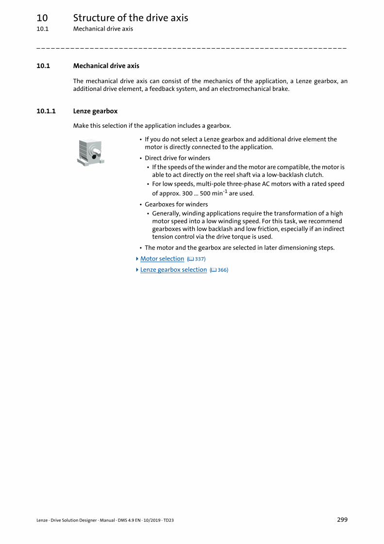
10 Structure of the drive axis10.1 Mechanical drive axis
_ _ _ _ _ _ _ _ _ _ _ _ _ _ _ _ _ _ _ _ _ _ _ _ _ _ _ _ _ _ _ _ _ _ _ _ _ _ _ _ _ _ _ _ _ _ _ _ _ _ _ _ _ _ _ _ _ _ _ _ _ _ _ _
10.1 Mechanical drive axis
The mechanical drive axis can consist of the mechanics of the application, a Lenze gearbox, anadditional drive element, a feedback system, and an electromechanical brake.
10.1.1 Lenze gearbox
Make this selection if the application includes a gearbox.
• If you do not select a Lenze gearbox and additional drive element the motor is directly connected to the application.
• Direct drive for winders• If the speeds of the winder and the motor are compatible, the motor is
able to act directly on the reel shaft via a low-backlash clutch.• For low speeds, multi-pole three-phase AC motors with a rated speed
of approx. 300 ... 500 min-1 are used.
• Gearboxes for winders• Generally, winding applications require the transformation of a high
motor speed into a low winding speed. For this task, we recommend gearboxes with low backlash and low friction, especially if an indirect tension control via the drive torque is used.
• The motor and the gearbox are selected in later dimensioning steps.
Motor selection ( 337)
Lenze gearbox selection ( 366)
Lenze · Drive Solution Designer · Manual · DMS 4.9 EN · 10/2019 · TD23 299

10 Structure of the drive axis10.1 Mechanical drive axis
_ _ _ _ _ _ _ _ _ _ _ _ _ _ _ _ _ _ _ _ _ _ _ _ _ _ _ _ _ _ _ _ _ _ _ _ _ _ _ _ _ _ _ _ _ _ _ _ _ _ _ _ _ _ _ _ _ _ _ _ _ _ _ _
10.1.2 Additional drive element
Make this selection if the application includes an additional drive element.
10.1.3 Feedback
Make this selection if the application includes a feedback.
10.1.4 Electromechanical brake
Make this selection if the application includes an electromechanical brake.
• If you do not select a Lenze gearbox and additional drive element the motor is directly connected to the application.
• DSD can simulate a user-definable mechanical ratio (additional drive component) with a toothed belt, flat belt, V-belt, chain, gear, or an individual gearbox.
• The additional drive element can be placed between the application and the motor or between the application and the Lenze gearbox.
• Additional drive element in winding applications.• Toothed belts as mechanical transmission elements between the
drive and the winder are very well-suited because they have low friction and good damping characteristics.
• Cardan shafts as axial coupling are suitable for big reels in center winding machines if the reels must be moved together with their pedestals for the winding process.
• Axial couplings (e.g. cardan shafts) between the winding shaft and the motor or the gearbox output must be dimensioned in a low backlash manner.
• Data for the additional drive element is entered in a later dimensioning step. Selection of an additional drive element ( 377)
• For drives with a servo control a feedback system is required. A servo control without a feedback system cannot be dimensioned in the DSD.
• Make the selection if a user motor with feedback system is used. Display of user motor ( 303)
• The feedback system is selected in a later dimensioning step. Feedback selection ( 394)
• The electromechanical brake is only checked if a parameter has been created for the brake in the motion profile. Motion design ( 240)
• Make the selection if a user motor with electromechanical brake is used. Display of user motor ( 303)
• The electromechanical brake is selected in a later dimensioning step. Mechanical brake selection ( 360)
300 Lenze · Drive Solution Designer · Manual · DMS 4.9 EN · 10/2019 · TD23

10 Structure of the drive axis10.2 Electrical drive axis
_ _ _ _ _ _ _ _ _ _ _ _ _ _ _ _ _ _ _ _ _ _ _ _ _ _ _ _ _ _ _ _ _ _ _ _ _ _ _ _ _ _ _ _ _ _ _ _ _ _ _ _ _ _ _ _ _ _ _ _ _ _ _ _
10.2 Electrical drive axis
10.2.1 Motor direct on line
Make this selection if you want to use the Lenze Smart Motor for the drive.
The way to the Lenze Smart Motor
10.2.2 Inverter with mains supply (single-axis application)
Make this selection if the inverter is directly connected to the supply system.
10.2.3 Inverter with DC supply (multi-axis application)
Make this selection if the drive axis is part of a multi-axis system or if it is supposed to feed backexcessive energy back to the mains due to high regenerative power. This selection enables you tomake efficient use of regenerative power in the drive system.
• The Lenze Smart Motor is directly connected to the AC system.• There is no coupling via the DC bus.• Suitable for single drive axes without energy-efficient use of
the regenerative power.
• Operation of the inverter directly connected to the AC system (single axis drive).• There is no coupling via the DC bus.• Suitable for single drive axes without energy-efficient use of
the regenerative power.
• DSD only offers inverters that combine supply (rectifiers) and inverters in one device and that are suitable for a direct connection to the AC system.
• The connection to the AC system is made via a central power supply unit (power supply module or regenerative power supply module). The inverter is connected to the supply unit via the DC bus.
• The supply via the supply system and the electrical braking system can be configured in the "dimension multi-axis system" application. For this purpose, the DSD projects of the drive axes are loaded into the application.
• DSD offers inverters• that combine supply (rectifiers) and inverters in one device
and come with a DC-bus connection,• that do not have a supply (rectifiers) but only the inverter.
They are only suitable for being connected to the DC-bus.
Size the multi-axis system ( 186)
Lenze · Drive Solution Designer · Manual · DMS 4.9 EN · 10/2019 · TD23 301

10 Structure of the drive axis10.3 Drive concept
_ _ _ _ _ _ _ _ _ _ _ _ _ _ _ _ _ _ _ _ _ _ _ _ _ _ _ _ _ _ _ _ _ _ _ _ _ _ _ _ _ _ _ _ _ _ _ _ _ _ _ _ _ _ _ _ _ _ _ _ _ _ _ _
10.3 Drive concept
In the dimensioning step "Drive concept" you preselect the components for the drive axis:
• Gearbox
• Gearbox / motor mounting• Gearbox / motor mounting ( 307)
• Motor
• Inverter / motor mounting• Select built-in unit or decentralised inverter
• Inverter
• Traversing motor control• Control system ( 380)
The DSD helps with the selection of the right productsand checks the compatibility:
• Compatible components in the drop-down menus have a product name marked in black.
• Non-compatible components in the drop-down menus have a product name marked in grey or in italics.If you select a component that is non-compatible, the DSD proposes a possible combination of components. You can either accept the proposition or discard it.
302 Lenze · Drive Solution Designer · Manual · DMS 4.9 EN · 10/2019 · TD23

10 Structure of the drive axis10.3 Drive concept
_ _ _ _ _ _ _ _ _ _ _ _ _ _ _ _ _ _ _ _ _ _ _ _ _ _ _ _ _ _ _ _ _ _ _ _ _ _ _ _ _ _ _ _ _ _ _ _ _ _ _ _ _ _ _ _ _ _ _ _ _ _ _ _
10.3.1 Display of user motor
By making specific settings in the Mechanical and Drive concept dimensioning steps, user motors arealso shown for selection. In the Geared motor dimensioning step, you can select the motors whichare to be shown in the Motor selection dimensioning step.
• Make the settings according to fig. [10-1] in order that user motors are displayed in the DSD project.
[10-1] Display of user motors: Settings for drive dimensioning
Note!
In an existing DSD project, newly created user motors will only be available after the data base has been updated.• Re-execute the drive dimensioning in the DSD project starting from the Drive concept
step in order that newly created user motors are displayed in the Motor selection dimensioning step.
Lenze · Drive Solution Designer · Manual · DMS 4.9 EN · 10/2019 · TD23 303

10 Structure of the drive axis10.3 Drive concept
_ _ _ _ _ _ _ _ _ _ _ _ _ _ _ _ _ _ _ _ _ _ _ _ _ _ _ _ _ _ _ _ _ _ _ _ _ _ _ _ _ _ _ _ _ _ _ _ _ _ _ _ _ _ _ _ _ _ _ _ _ _ _ _
10.3.2 Gearbox
The gearboxes available can be divided into two groups:
• Axial gearboxes
• Bevel gearbox
In the following subchapters, the gearboxes available in the DSD are described. The tabularrepresentation makes it possible for you to easily compare the properties to each other.
The Lenze Smart Motor can only be combined with Lenze gearboxes of the g500 series.
See also Selection help: Products for drive systems (without winders) ( 326)
Selection help: Products for winding drive systems ( 327)
Display of user motor ( 303)
304 Lenze · Drive Solution Designer · Manual · DMS 4.9 EN · 10/2019 · TD23

10 Structure of the drive axis10.3 Drive concept
_ _ _ _ _ _ _ _ _ _ _ _ _ _ _ _ _ _ _ _ _ _ _ _ _ _ _ _ _ _ _ _ _ _ _ _ _ _ _ _ _ _ _ _ _ _ _ _ _ _ _ _ _ _ _ _ _ _ _ _ _ _ _ _
10.3.2.1 Properties of the axial gearbox
10.3.2.2 Properties of the right-angle gearbox
Planetary gearboxesg700-P
Helical gearboxg500-H
Shaft-mounted helical gearboxg500-S
Illustration
Short description One-, two-, or three-stage planetary gearbox with a coaxial input shaft
and output shaft
Two- or three-stage helical gearbox with a coaxial input shaft and
output shaft
Two- or three-stage helical gearbox, flat design, input and output shaft in
parallel
Torque density High Medium Medium
Efficiency High High High
Backlash Very low Low Low
Number of frame sizes 5 13 11
Rated torque 20 … 800 Nm 45 … 14000 Nm 130 … 19000 Nm
Ratio 3.0 … 512 3.0 … 370 3.0 … 500
Shaft Solid shaft Solid shaft Solid/hollow shaft
Design Flange Base/flange Base/flange
Motor mounting Standard mounting Direct and standard mounting Direct/standard mounting
The data correspond to the device version stored in DSD
Bevel gearboxg350-B with m300 SmartMotor
Bevel gearboxg500-B
Illustration
Short description Single-stage bevel gearbox, drive shaft to driven shaft 90°
Two- or three-stage bevel gearbox, input shaft to output shaft 90°
Torque density Medium Medium
Efficiency High High
Backlash Low Low
Number of frame sizes 3 12
Rated torque 20 … 55 Nm 45 … 20000 Nm
Ratio 11.75 4.0 … 360
Shaft Solid/hollow shaft Solid/hollow shaft
Design Flange Base/flange
Motor mounting Integrated Direct/standard mounting
The data correspond to the device version stored in DSD
Lenze · Drive Solution Designer · Manual · DMS 4.9 EN · 10/2019 · TD23 305

10 Structure of the drive axis10.3 Drive concept
_ _ _ _ _ _ _ _ _ _ _ _ _ _ _ _ _ _ _ _ _ _ _ _ _ _ _ _ _ _ _ _ _ _ _ _ _ _ _ _ _ _ _ _ _ _ _ _ _ _ _ _ _ _ _ _ _ _ _ _ _ _ _ _
10.3.2.3 Lenze Smart motor
In the case of the Lenze Smart Motor, the parameter selection and settings are limited.
Parameter Description
Gearbox Gearbox preselection• The Lenze Smart Motor can only be combined with the g500 gearbox.
Gearbox / motor mounting Couple gearboxes to the motor via direct mounting or flange mounting.• The Lenze Smart Motor only allows for the direct mounting.• Read only.
Motor Lenze Smart motor• Read only.
306 Lenze · Drive Solution Designer · Manual · DMS 4.9 EN · 10/2019 · TD23

10 Structure of the drive axis10.3 Drive concept
_ _ _ _ _ _ _ _ _ _ _ _ _ _ _ _ _ _ _ _ _ _ _ _ _ _ _ _ _ _ _ _ _ _ _ _ _ _ _ _ _ _ _ _ _ _ _ _ _ _ _ _ _ _ _ _ _ _ _ _ _ _ _ _
10.3.3 Gearbox / motor mounting
Many Lenze gearboxes are provided for direct mounting. The first pinion of the gearbox is directlymounted to the motor shaft. By this, coupling elements and possible torque limitations by clutchesare not required, and the drive is provided with a higher mechanical stiffness.
Flange mounting means coupling the motor shaft with the gearbox shaft via a clutch. The couplingflanges of the motor and the gearbox are coupled via an adapter.
[10-2] Lenze gearbox with flange mounting (left) and direct mounting (right)
Tip!
Flange mounting allows for a larger variety of motor-gearbox combinations. In addition,the motor can be replaced more easily if necessary.• Create an alternative DSD project and select flange mounting in the Drive concept
dimensioning step if you cannot find a suitable solution with the direct mounting selection.
• Compare the differences, e.g. via the Project comparison.
User motor
A user motor can only be coupled using a gearbox with flange mounting.
• Select flange mounting so that user motors are shown in the Drive dimensioning dimensioning step. Display of user motor ( 303)
Lenze Smart motor
The Lenze Smart Motor is only intended for direct mounting. It is not possible change the setting inthe DSD.
Lenze · Drive Solution Designer · Manual · DMS 4.9 EN · 10/2019 · TD23 307

10 Structure of the drive axis10.3 Drive concept
_ _ _ _ _ _ _ _ _ _ _ _ _ _ _ _ _ _ _ _ _ _ _ _ _ _ _ _ _ _ _ _ _ _ _ _ _ _ _ _ _ _ _ _ _ _ _ _ _ _ _ _ _ _ _ _ _ _ _ _ _ _ _ _
10.3.4 Motor
In the following subchapters, the motors available in the DSD are described. The tabularrepresentation makes it possible for you to easily compare the properties to each other.
See also Selection help: Products for drive systems (without winders) ( 326)
Selection help: Products for winding drive systems ( 327)
Display of user motor ( 303)
10.3.4.1 Features of synchronous servo motors
MCS m850
Illustration
Short description Highly dynamic synchronous servo motor, high power density
Synchronous servo motor
Enclosure IP 54 / IP 65 IP 54
Dynamics Very high High
Mass inertia Very low Low
Overload capacity Very high High
Power density Very high High
Field weakening Medium (only with Servo Drives 9400) Medium
Detent torque(with regard to M0)
<1 % < 2 %
Total torque ripple for Mn 2.5 % –
Number of frame sizes 5 3
Performance 0.25 … 15.80 kW 2.0 … 9.20 kW
Speed 1050 … 6000 rpm 2500 … 4000 min-1
Continuous torque 0.50 … 72 Nm 4.8 … 35 Nm
Square dimension/diameter 6, 9, 12, 14, 19 cm 12, 14, 19 cm
Shaft height – –
Fan/brake Axial-flow blower, permanent magnet holding brake No fan, spring-applied brake, permanent magnet holding brake
Feedback system Resolver, SinCos absolute value encoder, incremental encoder with communication signal, One Cable
Technology (depending on the power range and only with the i950 servo inverter)
Resolver, SinCos absolute value encoder, One Cable Technology (depending on the power range and only
with the i950 servo inverter)
Gearbox mounting Direct mounting or standard mounting Direct mounting or standard mounting
Note – –
– Not possible / not available
The data correspond to the device version stored in DSD
308 Lenze · Drive Solution Designer · Manual · DMS 4.9 EN · 10/2019 · TD23

10 Structure of the drive axis10.3 Drive concept
_ _ _ _ _ _ _ _ _ _ _ _ _ _ _ _ _ _ _ _ _ _ _ _ _ _ _ _ _ _ _ _ _ _ _ _ _ _ _ _ _ _ _ _ _ _ _ _ _ _ _ _ _ _ _ _ _ _ _ _ _ _ _ _
10.3.4.2 Features of asynchronous servo motors
MCA MQA SDSGA
Illustration
Short description Totally enclosed fan-cooled asynchronous servo motor
Enclosed-ventilated asynchronous servo motor, high dynamic
performance and power density
Asynchronous servo motor, smooth housing, options for inverter
operation
Enclosure IP 23 / 54 / IP 65 IP 23 IP 54 / IP 55
Dynamics High Very high Medium
Mass inertia Low Very low High
Overload capacity Very high Very high High
Power density High Very high Medium
Field weakening High High High
Detent torque(with regard to M0)
None None None
Total torque ripple for Mn 3.5 ... 4.5 % 3.5 ... 4.5 % –
Number of frame sizes 9 3 3
Performance 0.80 … 53.8 kW 10.60 … 60.2 kW 0.075 … 0.60 kW
Speed 550 ... 4160 min-1 550 ... 2935 min-1 2700 rpm
Continuous torque 2 … 295 Nm 66.2 … 296 Nm 0.27 … 1.9 Nm
Square dimension/diameter 10, 13, 14, 17, 19, 20, 21, 22, 26 cm 20, 22, 26 cm 75, 85, 95 mm
Shaft height – 100, 112, 132 mm 38, 43, 47 mm
Fan/brake Axial-flow fan, spring-applied brake or permanent magnet holding brake
Radial-flow blower, spring-applied brake
No fan, spring-applied brake or permanent magnet holding brake
Feedback system Resolver, incremental encoder, SinCos encoder, SinCos absolute
value encoder
Resolver, incremental encoder, SinCos encoder, SinCos absolute
value encoder
Resolver
Gearbox mounting Direct mounting or standard mounting
Standard mounting Direct mounting or standard mounting
Note – Cannot be combined with Lenze gearbox in DSD
–
– Not possible / not available
The data correspond to the device version stored in DSD
Lenze · Drive Solution Designer · Manual · DMS 4.9 EN · 10/2019 · TD23 309

10Stru
cture of th
e drive axis10.3
Drive con
cept
310Len
ze · Drive Solu
tion D
esigner · M
anu
al · DM
S 4.9 EN · 10/2019 · TD
23
_ _ _ _ _ _ _ _ _ _ _ _ _ _ _ _ _ _ _ _ _ _ _ _ _ _ _ _ _ _ _ _ _ _ _ _ _ _ _ _ _ _ _ _ _ _ _ _ _ _ _ _ _ _ _ _ _ _ _ _ _ _ _ _
10.3.4.3 Features of three-phase AC motors
m550-P SmartMotor m300
ter y class
Suitable for inverter operation, efficiency class
IE3
Electronic motor with permanently adjustable
speed, efficiency class IES2
IP 55 / IP 65 / IP 66 IP 55 / IP 65
Medium Medium
Medium Medium
Medium High (4-fold)
Medium Medium
Medium –
3.5 ... 4.5 % –
13 2
0.75 … 52.5 kW 0.46 … 1.36 kW
-1 1400, 2500 min-1 500 … 2600 rpm
5.0 … 194 Nm 1.75 … 5.0 Nm
– –
80 … 180 mm 63 … 80 mm
r axial pplied
Axial-flow blower or axial integral fan, spring-applied
brake
Axial-flow integral fan, spring-applied brake
(optional)
der Incremental encoder, SinCos absolute value encoder
–
g Direct mounting or standard mounting
Direct mounting or standard mounting
in earbox
– –
MDXMA MFxMA MHxMA m540-P
Illustration
Short description Suitable for inverter operation, efficiency class
IE1
Optimised for inverter operation, rated frequency
of 120 Hz
Suitable for inverter operation, efficiency class
IE2
Suitable for inveroperation, efficienc
IE3
Enclosure IP 54 / IP 55 IP 54 / IP 55 IP 54 / IP 55 IP 55 / IP 65
Dynamics Medium High Medium Medium
Mass inertia Medium Low Medium Medium
Overload capacity Medium Medium Medium Medium
Power density Medium High Medium Medium
Field weakening Medium Medium Medium Medium
Total torque ripple for Mn 3.5 ... 4.5 % 3.5 ... 4.5 % 3.5 ... 4.5 % 3.5 ... 4.5 %
Number of frame sizes 11 7 9 14
Performance 0.06 … 53 kW 0.55 … 22 kW 0.75 … 78 kW 1.5 … 87 kW
Speed 900, 1400, 2500, 2800 min-1 3500 min-1 1400, 2500 min-1 1400, 2500 min
Continuous torque 0.33 … 290 Nm 1.5 … 59 Nm 4.2 … 290 Nm 10 … 354 Nm
Square dimension/diameter – – – –
Shaft height 63 … 225 mm 63 … 132 mm 80 … 225 mm 90 … 250 mm
Fan, brake Axial-flow blower or axial integral fan, spring-applied
brake
Axial-flow blower or axial integral fan, spring-applied
brake
Axial-flow blower or axial integral fan, spring-applied
brake
Axial-flow blower ointegral fan, spring-a
brake
Feedback system Resolver, incremental encoder, SinCos absolute
value encoder
Resolver, incremental encoder, SinCos absolute
value encoder
Resolver, incremental encoder, SinCos absolute
value encoder
Incremental enco
Gearbox mounting Direct mounting or standard mounting
Direct mounting or standard mounting
Direct mounting or standard mounting
Direct mountin
Note – – – Only available combination with a g
– Not possible / not available
The data correspond to the device version stored in DSD

10 Structure of the drive axis10.3 Drive concept
_ _ _ _ _ _ _ _ _ _ _ _ _ _ _ _ _ _ _ _ _ _ _ _ _ _ _ _ _ _ _ _ _ _ _ _ _ _ _ _ _ _ _ _ _ _ _ _ _ _ _ _ _ _ _ _ _ _ _ _ _ _ _ _
10.3.4.4 Motors for winding drives
Asynchronous motors
Three-phase asynchronous motors are the standard solution to most winding applications. They arecost-effective and can be operated in wide ranges of the field weakening without any difficulty. Dueto their high inherent inertia, they are well-suited for handling the high mass inertias of the reel inthe control system in a stable manner.
In combination with belt ratios, asynchronous motors with low rated speeds (higher-pole motors or4-pole motors with 29-Hz technology) and optimally used field weakening are very well-suited formany winding applications.
Generally, blowers are required for cooling the motors since the smallest speeds result in thehighest power loss. DSD checks the thermal motor utilisation.
Synchronous motors
Synchronous servo motors are used if the construction requires compact designs. Synchronousservo motors are only suitable to a limited extent for torque-controlled drives (indirect tensioncontrol) and for very accurate repeatability of the material tensile force. On the one hand themagnetisation is strongly temperature-dependent which can be hardly compensated for, and onthe other hand the detent torques have an interfering impact. The achievable field weakening isconsiderably lower than with asynchronous motors. The characteristic curve of the motor shows themax. field weakening range.
Tandem motor systems
In case of greater motor powers or very big reels, every side of the winding shaft can be equippedwith a motor. That way, the drive torque is symmetrically shared. Torsions in the winding materialare minimised.
• Two asynchronous motors can be connected in parallel to an inverter without any difficulty and are hence a cost-effective solution.
• Concepts including two inverters are also possible. The torque division is carried out symmetrically via the control system.
• Synchronous servo motors require one inverter each. A parallel connection of the motors is not possible.
Lenze · Drive Solution Designer · Manual · DMS 4.9 EN · 10/2019 · TD23 311

10 Structure of the drive axis10.3 Drive concept
_ _ _ _ _ _ _ _ _ _ _ _ _ _ _ _ _ _ _ _ _ _ _ _ _ _ _ _ _ _ _ _ _ _ _ _ _ _ _ _ _ _ _ _ _ _ _ _ _ _ _ _ _ _ _ _ _ _ _ _ _ _ _ _
10.3.4.5 User motors
The motor technology is defined when a user motor is created.Manage user motors ( 447)
In order that the user motor is shown in the Drive dimensioning dimensioning step, you must selectthe desired motor technology instead of a motor in the Drive concept dimensioning step.
Selection of the motor technology Defining the motor technology
The motor technology is selected in the Drive concept dimensioning step.
The motor technology is defined via the Manage user motors function."Technology" tab ( 451)
Possible selection:• Three-phase AC motor• Synchronous servo motor• Asynch. servo motor
312 Lenze · Drive Solution Designer · Manual · DMS 4.9 EN · 10/2019 · TD23

10Stru
cture of th
e drive axis10.3
Drive con
cept
Lenze · D
rive Solution
Design
er · Man
ual · D
MS 4.9 EN
· 10/2019 · TD23
313
_ _ _ _ _ _ _ _ _ _ _ _ _ _ _ _ _ _ _ _ _ _ _ _ _ _ _ _ _ _ _ _ _ _ _ _ _ _ _ _ _ _ _ _ _ _ _ _ _ _ _ _ _ _ _ _ _ _ _ _ _ _ _ _ 10.3.5 Inverter
In the subchapters, the inverters available in DSD are described. The tabular representation makes it possible for you to easily compare the
fective. A speed feedback is not necessarily
i510 i550
ersal frequency inverter, V/f ol, sensorless vector control, rless control for synchronous rs, overload capacity of up to
00 %, memory module
Scalable frequency inverter, V/f control with feedback, sensorless
vector control, sensorless control for synchronous motors, torque control,
overload capacity of up to 200 %, memory module, optional safety
features
ut an integrated EMC filter:C 170 … 264 V: 0.25 … 2.2 kW
170 … 264 V: 4.0 … 5.5 kWh an integrated EMC filter:170 … 264 V: 0.25 … 2.2 kW340 … 528 V: 0.37 … 11 kW
Without an integrated EMC filter:1/3 AC 170 … 264 V: 0.25 … 2.2 kW
1 AC 90 … 132 V: 0.25 … 1.1 kW3 AC 170 … 264 V: 4.0 … 5.5 kWWith an integrated EMC filter:
1 AC 170 … 264 V: 0.25 … 2.2 kW3 AC 340 … 528 V: 0.37 … 110 kW
UL, CSA, EAC, RoHS, IE2 in pliance with EN 50598-2
CE, UL, CSA, EAC, RoHS, IE2 in compliance with EN 50598-2
TN, TT, IT TN, TT, IT
2, 4, 8, 16 kHz 2, 4, 8, 16 kHz
– –
– –
properties to each other.
See also Selection help: Products for drive systems (without winders) ( 326)
Selection help: Products for winding drive systems ( 327)
10.3.5.1 Features of frequency inverters
Frequency inverters are suitable for simple, speed-controlled drive tasks, and they are cost-efrequired.
Inverter Drives 8400 BaseLine Inverter Drives 8400 StateLine Inverter Drives 8400 HighLine
Illustration
Short description Frequency inverters with integrated keypad, V/f control,
sensorless vector control, overload capacity up to 200 %, pluggable memory chip for the
parameter set
Scalable frequency inverter, V/f control with feedback, sensorless vector control, overload capacity up to 200 %, pluggable memory clip for parameter set, optionally with integrated safety functions,
free function block interconnection, sensorless
control for synchronous motors
Scalable frequency inverter, V/f control with feedback, sensorless vector control, overload capacity up to 200 %, pluggable memory clip for parameter set, optionally with integrated safety functions,
free function block interconnection, point-to-point positioning, sensorless control for synchronous motors, servo
control
Univcontr
sensomoto
2
Voltage range/power range 1 AC 180 … 264 V: 0.25 … 2.2 kW3 AC 320 … 550 V: 0.37 … 3.0 kW
1 AC 180 … 264 V: 0.25 … 2.2 kW3 AC 320 … 550 V: 0.37 … 45 kW
1 AC 180 … 264 V: 0.25 … 2.2 kW3 AC 320 … 550 V: 0.37 … 45 kW
Witho1/3 A
3 ACWit
1 AC3 AC
Approvals CE, UL, GOST-R, RoHS CE, UL, GOST-R, RoHS CE, UL, GOST-R, RoHS CE,com
Permissible power systems TN, TT TN, TT, IT TN, TT, IT
Switching frequencies 2, 4, 8, 16 kHz 2, 4, 8, 16 kHz 2, 4, 8, 16 kHz
Mechanical design
Built-in unit
Push-through technique – (up to 15 kW) (up to 15 kW)
Cold plate technique – (up to 22 kW) (up to 22 kW)

10Stru
cture of th
e drive axis10.3
Drive con
cept
314Len
ze · Drive Solu
tion D
esigner · M
anu
al · DM
S 4.9 EN · 10/2019 · TD
23
_ _ _ _ _ _ _ _ _ _ _ _ _ _ _ _ _ _ _ _ _ _ _ _ _ _ _ _ _ _ _ _ _ _ _ _ _ _ _ _ _ _ _ _ _ _ _ _ _ _ _ _ _ _ _ _ _ _ _ _ _ _ _ _
Enclosure IP 20 IP 20 IP 20 IP 20 IP 20
–
– –
– (3 AC 400/480 V)
– (only for the asynchronous motor)
– –
2/1 Standard I/O: 2/1Application I/O: 2/2
5/1 Standard I/O: 5/1Application I/O: 7/2
– –
1 1
–
–
– –
Inverter Drives 8400 BaseLine Inverter Drives 8400 StateLine Inverter Drives 8400 HighLine i510 i550
Operation in generator mode
Integrated brake resistor (3 AC 400/500 V)
External brake transistor (1 AC 230/240 V) – –
DC-bus connection –
Control types
VFC plus (V/f control)
SLVC (sensorless vector control)
V/f control –
VFC plus eco (V/f control,energetically optimised)
–
SLPSM (sensorless control forsynchronous motors)
–
SC (servo control) – – (only for the asynchronous motor)
Drive function
Voltage / frequency control
Torque control –
closed-loop speed control –
PID controller
Programmability
Parameterisation
Function block programming –
I/O
Analog input / output 1/0 1/1 2/2
Digital input / output 4/1 4/1 7/3
Connection of motor holdingbrake
– –
Relay output 1 1 1
Speed feedback –
PTC –
Linear motor temperature sensor(KTY/PT1000)
– – –
I×t monitoring

10Stru
cture of th
e drive axis10.3
Drive con
cept
Lenze · D
rive Solution
Design
er · Man
ual · D
MS 4.9 EN
· 10/2019 · TD23
315
_ _ _ _ _ _ _ _ _ _ _ _ _ _ _ _ _ _ _ _ _ _ _ _ _ _ _ _ _ _ _ _ _ _ _ _ _ _ _ _ _ _ _ _ _ _ _ _ _ _ _ _ _ _ _ _ _ _ _ _ _ _ _ _ Fieldbus systems
–
– –
–
– –
– –
– –
–
–
–
–
–
–
– –
Inverter Drives 8400 BaseLine Inverter Drives 8400 StateLine Inverter Drives 8400 HighLine i510 i550
CAN bus
PROFIBUS –
Interbus –
Modbus RTU – – –
Modbus TCP/IP – – –
LECOM – – –
AS interface – – –
DeviceNet – – –
Ethernet TCP/IP –
PROFINET –
EtherCAT –
POWERLINK –
Modbus TCP/IP – – –
Safety functions
Safe torque off –
Diagnostics support
LEDs
Integrated keypad – –
External keypad –
PC interface
Memory module
Standard Variant
Option – Not possible / not available
The data correspond to the device version stored in DSD

10 Structure of the drive axis10.3 Drive concept
_ _ _ _ _ _ _ _ _ _ _ _ _ _ _ _ _ _ _ _ _ _ _ _ _ _ _ _ _ _ _ _ _ _ _ _ _ _ _ _ _ _ _ _ _ _ _ _ _ _ _ _ _ _ _ _ _ _ _ _ _ _ _ _
10.3.5.2 Servo inverter properties
Servo inverters are highly dynamic current-controlled systems for speed, torque, or position control.They are characterised by a high speed accuracy, a great torque setting range, and a high overloadcapability. A speed feedback is always required to operate them.
• Position-controlled systems are suitable for drive tasks as e.g. positioning, electronic gearbox or electronic cam.
i950 servo inverter Servo Drives 9400 HighLine
Inverter Drives 8400 TopLine
i700 servo inverter
Illustration
Short description Intelligent servo inverter for synchronous and
asynchronous motors. Suitable for speed-
controlled or position-controlled applications as
well as positioning applications, modular
fieldbus communication and encoder interfaces, pluggable SD card for
parameter set and application data
Intelligent servo inverter for single-axis and multi-
axis applications, function block structure that can be
freely interconnected, activation via digital
inputs/outputs and/or fieldbus, modular safety engineering, innovative
rear panel system, pluggable memory chip
for the parameter set
Servo inverter for synchronous and
asynchronous servo motors, suitable for speed
and position-controlled applications as well as
positioning applications, multi encoder input,
optionally with integrated safety engineering,
fieldbus communication, pluggable memory chip
for the parameter set
Servo inverter for single-axis and multi-axis
applications, compact design and connection system, flexible motor
control for synchronous and asynchronous motors,
multi-axis system with central supply
Voltage range/power range Single Drive:3 AC 180 … 528 V:
0.55 … 110 kWDC 260 … 775 V: 0.55 … 110 kW
Single Drive:3 AC 180 … 550 V:
0.37 … 370 kWDC 260 … 775 V: 0.37 … 315 kW
Multi Drive:DC 260 … 775 V:
0.37 … 30 kW
1 AC 180 … 264 V: 0.25 … 2.2 kW
3 AC 320 … 550 V: 0.37 … 45 kW
Power supply module:3 AC 320 … 528 VDC 260 … 775 V
Axis module:DC 260 … 775 V:
0.75 … 15 kW
Approvals CE, UL 61800-5-1, RoHS CE, UL 61800-5-1, RoHS CE, UL 508C, GOST-R, RoHS CE, UL 508C, RoHS
Permissible power systems TN, TT, IT TN, TT, IT TN, TT, IT,RoHS-compliant
TN, TT, IT
Switching frequencies 2, 4, 8, 16 kHz 1, 2, 4, 8, 16 kHz 2, 4, 8, 16 kHz 4, 8, 16 kHz
Mechanical design
Built-in unit
Push-through technique – – (up to 15 kW)
Cold plate technique – – (up to 22 kW)
Installation backplane – (SingleDrive up to 11 kW)
(MultiDrive up to 15 kW)
– –
Enclosure IP 20 IP 20 IP 20 IP 20
Operation in generator mode
Integrated brake resistor (SingleDrive, power supply
modules)
External brake transistor – – – –
Regenerative – – –
Control types
VFC plus (V/f control)
SLVC (sensorless vector control) – –
SLPSM (sensorless control forsynchronous motors)
– – –
SC (servo control)
316 Lenze · Drive Solution Designer · Manual · DMS 4.9 EN · 10/2019 · TD23

10 Structure of the drive axis10.3 Drive concept
_ _ _ _ _ _ _ _ _ _ _ _ _ _ _ _ _ _ _ _ _ _ _ _ _ _ _ _ _ _ _ _ _ _ _ _ _ _ _ _ _ _ _ _ _ _ _ _ _ _ _ _ _ _ _ _ _ _ _ _ _ _ _ _
Drive function
Voltage / frequency control
Torque control
closed-loop speed control
PID controller
Motion Control
Programmability
Parameterisation
Function block programming – –
IEC 61131-3 – –
I/O
Analog input / output 1/1 2/2 2/2 –
Digital input / output 4/1 9/4 7/3 2/0
Connection of motor holdingbrake
–
Relay output – – 1 1
Speed feedback 2 (3 ) 3 1
Emulation of feedback output – 1 –
PTC
Linear motor temperature sensor(KTY/PT1000)
I2×t monitoring
Fieldbus systems
CAN – –
PROFIBUS – –
Interbus – – – –
CANopen –
Modbus RTU – – – –
Modbus TCP/IP – – – –
LECOM – – – –
AS interface – – –
DeviceNet – – –
Ethernet TCP/IP – – –
PROFINET –
EtherCAT
POWERLINK – –
EtherNet/IP –
Safety functions
Safe torque off
Further safety functions –
Diagnostics support
LEDs
Integrated keypad – – – –
External keypad – –
PC interface
Memory module –
Standard Variant
Option – Not possible / not available
The data correspond to the device version stored in DSD
i950 servo inverter Servo Drives 9400 HighLine
Inverter Drives 8400 TopLine
i700 servo inverter
Lenze · Drive Solution Designer · Manual · DMS 4.9 EN · 10/2019 · TD23 317

10 Structure of the drive axis10.3 Drive concept
_ _ _ _ _ _ _ _ _ _ _ _ _ _ _ _ _ _ _ _ _ _ _ _ _ _ _ _ _ _ _ _ _ _ _ _ _ _ _ _ _ _ _ _ _ _ _ _ _ _ _ _ _ _ _ _ _ _ _ _ _ _ _ _
10.3.5.3 Features of decentralised inverters
See also Inverter Drives 8400 motec: motor mounting or single mounting ( 320)
Inverter Drives 8400 motec Inverter Drives 8400 protec i550 protec
Illustration
Short description Frequency inverters for motor and wall mounting, V/f control with/without encoder, vector control without speed feedback, optionally with integrated safety functions, fieldbus communication, pluggable memory chip for the parameter set
Frequency inverters for wall mounting, vector control with/without speed feedback, overload capacity up to 200 %, optionally with integrated safety functions, fieldbus communication, pluggable memory chip for the parameter set
Scalable frequency inverter, V/f control with/without feedback, sensorless vector control, sensorless control for synchronous motors, torque control, overload capacity of up to 200%, memory module, optional safety engineering
Voltage range/power range 3 AC 320 … 528 V: 0.37 … 7.5 kW 3 AC 320 … 550 V:0.75 … 4.0 kW (1st version)
7.5 kW (2nd version)
Without an integrated EMC filter:1/3 AC 170 … 264 V: 0.37 … 2.2 kW
1 AC 90 … 132 V: 0.37 … 1.1 kWWith an integrated EMC filter:
1 AC 170 … 264 V: 0.37 … 2.2 kW3 AC 340 … 528 V: 0.75 … 2.2 kW
Approvals CE, UL508C CE, UL508C CE, UL, CSA, EAC, RoHS, IE2 in compliance with EN 50598-2
Permissible power systems TN, TT, IT TN, TT TN, TT, IT ()
Switching frequencies 4, 8, 16 kHz 2, 4, 8, 16 kHz 2, 4, 8, 12, 16 kHz
Mechanical design
Built-in unit – –
Push-through technique – – –
Cold plate technique – –
Motor mounting – –
Wall mounting
Enclosure IP 54 / IP 65 IP 65 IP 31, IP 65
Operation in generator mode
Integrated brake resistor
External brake transistor – – (3 AC 400/480 V)
Regenerative – – –
Control types
VFC plus (V/f control)
SLVC (sensorless vector control)
SLPSM (sensorless control forsynchronous motors)
V/f control
SC (servo control) – (only with asynchronous motor)
Drive function
Voltage / frequency control
Torque control –
closed-loop speed control (only with asynchronous motor)
PID controller
Motion Control – – –
Programmability
Parameterisation
Function block programming – –
IEC 61131-3 – – –
318 Lenze · Drive Solution Designer · Manual · DMS 4.9 EN · 10/2019 · TD23
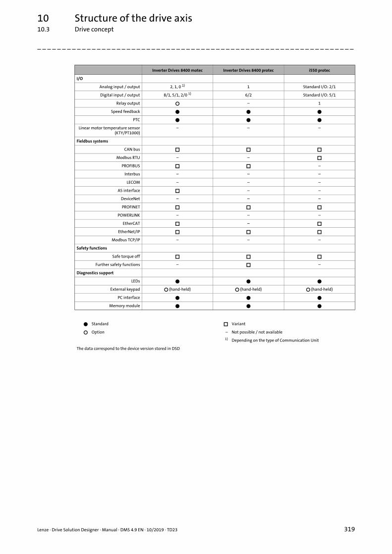
10 Structure of the drive axis10.3 Drive concept
_ _ _ _ _ _ _ _ _ _ _ _ _ _ _ _ _ _ _ _ _ _ _ _ _ _ _ _ _ _ _ _ _ _ _ _ _ _ _ _ _ _ _ _ _ _ _ _ _ _ _ _ _ _ _ _ _ _ _ _ _ _ _ _
I/O
Analog input / output 2, 1, 0 1) 1 Standard I/O: 2/1
Digital input / output 8/1, 5/1, 2/0 1) 6/2 Standard I/O: 5/1
Relay output – 1
Speed feedback
PTC
Linear motor temperature sensor(KTY/PT1000)
– – –
Fieldbus systems
CAN bus
Modbus RTU – –
PROFIBUS –
Interbus – – –
LECOM – – –
AS interface – –
DeviceNet – – –
PROFINET
POWERLINK – – –
EtherCAT –
EtherNet/IP
Modbus TCP/IP – – –
Safety functions
Safe torque off
Further safety functions – –
Diagnostics support
LEDs
External keypad (hand-held) (hand-held) (hand-held)
PC interface
Memory module
Standard Variant
Option – Not possible / not available
1) Depending on the type of Communication Unit
The data correspond to the device version stored in DSD
Inverter Drives 8400 motec Inverter Drives 8400 protec i550 protec
Lenze · Drive Solution Designer · Manual · DMS 4.9 EN · 10/2019 · TD23 319

10 Structure of the drive axis10.3 Drive concept
_ _ _ _ _ _ _ _ _ _ _ _ _ _ _ _ _ _ _ _ _ _ _ _ _ _ _ _ _ _ _ _ _ _ _ _ _ _ _ _ _ _ _ _ _ _ _ _ _ _ _ _ _ _ _ _ _ _ _ _ _ _ _ _
10.3.5.4 Inverter Drives 8400 motec: motor mounting or single mounting
In the "drive concept" sizing step of the DSD, you can go to Motor/inverter mounting and select"Decentralised inverter - motor mounting" or "Decentralised inverter - single mounting".
• Motor mounting: In further drive sizing. there is a fixed assignment between motor power and inverter power for Inverter Drives 8400 motec.
• Single mounting: In the further drive sizing, there is no fixed assignment for Inverter Drives 8400 motec between motor power and inverter power.• Sizing continues to be intended only for mounting on the motor. Sizing for a wall mounting
is not possible.• The installation feasibility is not checked.• A product configuration is not possible in the DSD.
[10-3] Inverter Drives 8400 motec: sizing examples in the DSD for motor mounting and single mounting
320 Lenze · Drive Solution Designer · Manual · DMS 4.9 EN · 10/2019 · TD23

10Stru
cture of th
e drive axis10.3
Drive con
cept
Lenze · D
rive Solution
Design
er · Man
ual · D
MS 4.9 EN
· 10/2019 · TD23
321
_ _ _ _ _ _ _ _ _ _ _ _ _ _ _ _ _ _ _ _ _ _ _ _ _ _ _ _ _ _ _ _ _ _ _ _ _ _ _ _ _ _ _ _ _ _ _ _ _ _ _ _ _ _ _ _ _ _ _ _ _ _ _ _ 10.3.6 Overview of motor/inverter control types
Synchronous servo motor Asynch. servo motor
MCS m850 SDSGA MCA MQA
3) 3) 1) 1) 1)
– –
– –
– –
– – –
– – –
– – –
– – –
– – – – –
– –
– – –
– – –
– – –
– – – – –
– –
– –
– –
– –
hc
Control system Encoders Three-phase AC motor
Yes No m540-P/m550-P (IE3)
MH (IE2) MF (120 Hz) MD (IE1)
Frequency inverter(Control cabinet devices)
Inverter Drives 8400
SC 1) 1) 1) 1)
SLVC
VFC plus 2)
VFC plus eco 2)
SLPSM – – – –
i510 SLVC
VFC plus
VFC plus eco
SLPSM – – – –
i550 SC 4) 5)
SLVC
VFC plus 4)
VFC plus eco
SLPSM – – – –
Servo inverter(Control cabinet devices)
Servo Drives 9400 HighLine
SC
SLVC
VFC plus
i950 servo inverter SC
VFC plus
i700 servo inverter SC
VFC plus
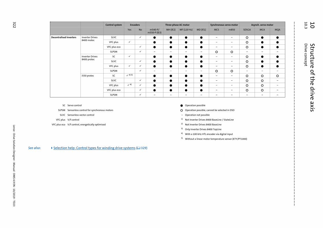
10Stru
cture of th
e drive axis10.3
Drive con
cept
322Len
ze · Drive Solu
tion D
esigner · M
anu
al · DM
S 4.9 EN · 10/2019 · TD
23
_ _ _ _ _ _ _ _ _ _ _ _ _ _ _ _ _ _ _ _ _ _ _ _ _ _ _ _ _ _ _ _ _ _ _ _ _ _ _ _ _ _ _ _ _ _ _ _ _ _ _ _ _ _ _ _ _ _ _ _ _ _ _ _
– –
– –
– –
– – –
– –
– –
– –
– – –
– –
– – –
– – –
– – –
– – – – –
ot be selected in DSD
BaseLine / StateLine
BaseLine
0 TopLine
oder via digital input
temperature sensor (KTY/PT1000)
hc
Control system Encoders Three-phase AC motor Synchronous servo motor Asynch. servo motor
Yes No m540-P/m550-P (IE3)
MH (IE2) MF (120 Hz) MD (IE1) MCS m850 SDSGA MCA MQA
See also: Selection help: Control types for winding drive systems ( 329)
Decentralised inverters Inverter Drives 8400 motec
SLVC
VFC plus
VFC plus eco
SLPSM – – – –
Inverter Drives 8400 protec
SC
SLVC
VFC plus
SLPSM – – – –
i550 protec SC 4) 5)
SLVC
VFC plus 4)
VFC plus eco
SLPSM – – – –
SC Servo control Operation possible
SLPSM Sensorless control for synchronous motors Operation possible, cann
SLVC Sensorless vector control – Operation not possible
VFC plus V/f control 1) Not Inverter Drives 8400
VFC plus eco V/f control, energetically optimised 2) Not Inverter Drives 8400
3) Only Inverter Drives 840
4) With a 100 kHz HTL enc
5) Without a linear motor

10 Structure of the drive axis10.3 Drive concept
_ _ _ _ _ _ _ _ _ _ _ _ _ _ _ _ _ _ _ _ _ _ _ _ _ _ _ _ _ _ _ _ _ _ _ _ _ _ _ _ _ _ _ _ _ _ _ _ _ _ _ _ _ _ _ _ _ _ _ _ _ _ _ _
10.3.6.1 Encoderless motor control for vertical conveyors/hoists
An application is referred to as a vertical conveyor if the gravitational force has a significant effecton the motor torque. Applications recognised by the Drive Solution Designer as a vertical conveyor:
• Cable-guided hoists and linear applications with an angle of tilt of more than 45° (belt drives, rack drives, spindle drives, travelling drives).
• Slider-crank mechanism with an angle of tilt of 45° ... 135° or 235° ... 315°.
• Eccentric lift tables.
Drive systems for vertical conveyors must ensure a reliable and continuous operation of theapplication at all times. For this task, a special motor management is required.
Drive systems with feedback are very well-suited for vertical conveyors. For applications withoutfeedback, the motor management must also ensure a continuous and safe operation of the drive,even without encoder, and for the transition phases lifting/lowering and lowering/lifting inparticular. During this four-quadrant operation, the motor control must also ensure safe operationof the "Zero-Hertz field frequency" operating status.
DSD efficiently supports the user during the drive dimensioning phase and
• provides suitable control types and encoderless drive systems for certain power ranges,
• considers the operating behaviour of the drive system during the dimensioning phase,
• checks necessary overdimensioning of the drive components and the max. permissible motor utilisation,
• detects the utilisation of the selected drive components,
• signalises exceedances of limit values by means of warning signals or notes.
Lenze · Drive Solution Designer · Manual · DMS 4.9 EN · 10/2019 · TD23 323

10 Structure of the drive axis10.3 Drive concept
_ _ _ _ _ _ _ _ _ _ _ _ _ _ _ _ _ _ _ _ _ _ _ _ _ _ _ _ _ _ _ _ _ _ _ _ _ _ _ _ _ _ _ _ _ _ _ _ _ _ _ _ _ _ _ _ _ _ _ _ _ _ _ _
Control types
All Lenze inverters are provided with the linear V/f control (VFC) which, however, requires anoverdimensioning of the inverter with regard to the motor. Moreover, the motor may only beutilised to approx. 75 % of the rated torque.
Servo Drives 9400 HighLine are provided with the special Voltage Vector Control (VVC) motormanagement which is suitable for vertical conveyors with encoderless drive systems. Thisprocedure ensures a motor excitement coordinated to each operating status. For this purpose, therated output current of the inverter has to be at least 120 % of the rated motor current.
Suitable control types
• VFC plus with VVCV/f control with linear V/f characteristic• VVC: Voltage Vector Control• VVC is activated via parameters• Suitable for motor power 55 kW• Contained in Servo Drives 9400 HighLine
• VFC plus linearV/f control with linear V/f characteristic• Suitable for motor power 7.5 kW (recommended limit value)• Contained in all Lenze inverters
Tip!• Lenze Servo Drives 9400 HighLine with VVC are recommended for vertical conveyors
with an encoderless drive system 55 kW.• Always execute drive systems >55 kW with feedback.
Unsuitable control types
• VFC plus quadraticV/f control with square-law V/f characteristic
• VFC plus ecoEnergetically optimised V/F control
• SLVCSensorless vector control
324 Lenze · Drive Solution Designer · Manual · DMS 4.9 EN · 10/2019 · TD23

10 Structure of the drive axis10.3 Drive concept
_ _ _ _ _ _ _ _ _ _ _ _ _ _ _ _ _ _ _ _ _ _ _ _ _ _ _ _ _ _ _ _ _ _ _ _ _ _ _ _ _ _ _ _ _ _ _ _ _ _ _ _ _ _ _ _ _ _ _ _ _ _ _ _
Tests in DSD
DSD carries out all tests for a safe dimensioning. Here, the following product-specific andprocedure-specific factors for utilisation and overdimensioning are assumed regarding application,motor and inverter.
• VFC plus with VVC (only possible with Servo Drives 9400 HighLine)• The motor is only utilised to the rated torque.• The rated output current of the inverter is at least 120 % of the rated motor current.
• VFC plus (possible for all inverters)• The motor is maximally utilised to 75 % of the rated torque.• The rated output current of the inverter is at least 170 % of the rated motor current.• Compared to the requirement of the application, the inverter is overdimensioned with an
overall factor of 2.27.
See also Hoist drive without counterweight ( 113)
Hoist drive with counterweight ( 122)
Note!
Observe the notes in the dimensioning protocol if• limit values have been exceeded,• dimensioning has been carried out with Servo Drives 9400 HighLine and the VFC plus
control type with VVC.• In order to activate VVC (Voltage Vector Control), you have to adapt parameters in
the inverter.
Lenze · Drive Solution Designer · Manual · DMS 4.9 EN · 10/2019 · TD23 325

10 Structure of the drive axis10.3 Drive concept
_ _ _ _ _ _ _ _ _ _ _ _ _ _ _ _ _ _ _ _ _ _ _ _ _ _ _ _ _ _ _ _ _ _ _ _ _ _ _ _ _ _ _ _ _ _ _ _ _ _ _ _ _ _ _ _ _ _ _ _ _ _ _ _
10.3.7 Selection help: Products for drive systems (without winders)
Conv
eyor
dri
ves
Mot
ion
driv
es
Hoi
st d
rive
s
Posi
tion
ing
driv
es
Coor
dina
ted
driv
es fo
rro
bots
Sync
hron
ous
driv
es
Cloc
k dr
ives
for c
ross
cut
ters
and
flyi
ng s
aws
Dri
ves
for e
lect
roni
c ca
m d
rive
s
Dri
ves
for
form
ing
proc
esse
s
Mas
ter a
nd t
ool d
rive
s
Dri
ves
for
pum
psan
d fa
ns
Servo inverter
Servo Drives 9400 HighLine +++ +++ +++ +++ +++ +++ +++ +++ +++ +++
i950 servo inverter +++ +++ +++ +++ +++ +++ +++ +++ +++ +++
Inverter Drives 8400 TopLine +++ +++ +++ +++ ++ +++ +++ ++ +++ +++ +++
i700 servo inverter 1) ++ +++ +++ +++ +++ +++ +++ +++ ++ +++
Frequency inverter
i510 ++ ++ ++ +++
i550 +++ +++ ++ + ++ ++ +++
Inverter Drives 8400 BaseLine +++ ++ ++ +++
Inverter Drives 8400 StateLine +++ +++ ++ ++ +++
Inverter Drives 8400 HighLine +++ +++ ++ +++ ++ +++ +++ +++
Inverter Drives 8400 motec +++ +++ ++ ++ +++
Inverter Drives 8400 protec +++ +++ ++ ++ ++ ++ ++ +++
i550 protec +++ +++ ++ + ++ ++ +++
Servo motors
MCA +++ ++ +++ +++ +++ +++ +++ +++ +++
MCS ++ ++ +++ +++ ++ +++ +++
m850 ++ ++ +++ +++ ++ +++ +++
MQA +++ +++ +++ +++ ++ +++ +++ +++ +++ +++ ++
Three-phase AC motors
MDxMA, MHxMA, m550-P, m540-P +++ +++ +++ ++ +++ ++ ++ +++ +++ +++
MFxMA +++ +++ +++ +++ +++ ++ ++ +++ +++ +++
Axial gearboxes/ratios
g700-P planetary gearbox ++ +++ ++ +++ +++ +++ +++ +++ ++ ++
g500-H helical gearbox +++ +++ +++ ++ ++ +++ +++ ++ +++ +++
g500-S shaft-mounted helical gearbox +++ +++ +++ ++ ++ +++ ++ ++ +++ +++
Traction drives, positive-fit 2) +++ +++ +++ +++ +++ +++ +++ +++ +++ ++ +++
Traction drives, friction-locked 3) +++ +++ O +++ +++ +++
Traction drives, chain +++ ++
Bevel gearbox
g500-B bevel gearbox +++ +++ +++ ++ ++ +++ +++ ++ +++ +++
+++ Very well suited 1) Operation with Lenze Motion Controller, e.g. P500 or C300
++ Well-suited 2) E. g. toothed belt, chain
+ Suited 3) E. g. V-belt, flat belt
Suitable with restrictions
326 Lenze · Drive Solution Designer · Manual · DMS 4.9 EN · 10/2019 · TD23

10Stru
cture of th
e drive axis10.3
Drive con
cept
Lenze · D
rive Solution
Design
er · Man
ual · D
MS 4.9 EN
· 10/2019 · TD23
327
_ _ _ _ _ _ _ _ _ _ _ _ _ _ _ _ _ _ _ _ _ _ _ _ _ _ _ _ _ _ _ _ _ _ _ _ _ _ _ _ _ _ _ _ _ _ _ _ _ _ _ _ _ _ _ _ _ _ _ _ _ _ _ _ 10.3.8 Selection help: Products for winding drive systems
cer position control (n) Speed control (n)
sed-loop speed control/en-loop speed control
Closed-loop speed control/open-loop speed control
+++ +++
+++ +++
+++ +++
+++ +++
+++ +++
+++ +++
+++ +++
++ ++
++ ++
+++ +++
+++ +++
++ ++
+++ +++
+++ +++
– –
v
F
F~FG FGActualposition
~
verter
v
F
M3~
n, M r
vact
Inverter
M = f(F, r)n = f(v, r)
2)
Tension ctrl open loop (M) Tension control closed loop (M)1)
Tension control closed loop (n)1)
Dan
Winder control mode
Traversing motor control Open-loop torque control Open-loop torque control closed-loop speed control Cloop
Axial gearboxes, ratios
g500-H helical gearbox ++ ++ ++
g500-S shaft-mounted helical gearbox ++ ++ ++
g700-P planetary gearbox ++ ++ ++
Toothed belt +++ +++ +++
Direct drive +++ +++ +++
Bevel gearbox
g500-B bevel gearbox ++ ++ ++
Servo motors
MCA +++ +++ +++
MCS ++ ++ ++
m850 ++ ++ ++
MQA +++ +++ +++
SDSGA +++ +++ +++
Three-phase AC motors
MDXMA ++ ++ ++
MFxMA
m550-P, m540-P +++ +++ +++
MHxMA +++ +++ +++
Inverters (IP 20)
i510 4) – – –
v
Fn, M r
M3~
Inverter
v
Fn, M r
M = f(F, r)n = f(v, r)
Fact
M3~
Inverter
v
Fn, M r
M = f(F, r)n = f(v, r)
Fact
M3~
Inverter
n, M
M3
In

10Stru
cture of th
e drive axis10.3
Drive con
cept
328Len
ze · Drive Solu
tion D
esigner · M
anu
al · DM
S 4.9 EN · 10/2019 · TD
23
_ _ _ _ _ _ _ _ _ _ _ _ _ _ _ _ _ _ _ _ _ _ _ _ _ _ _ _ _ _ _ _ _ _ _ _ _ _ _ _ _ _ _ _ _ _ _ _ _ _ _ _ _ _ _ _ _ _ _ _ _ _ _ _
i550 3) 6) – – 5) 5)
– –
5) 5)
5) 5)
5) 5)
5) 5)
with an ultrasonic sensor (optional)
nsor (KTY/PT1000) is not evaluated
le
l not possible
mpensation function
Tension ctrl open loop (M) Tension control closed loop (M)1)
Tension control closed loop (n)1)
Dancer position control (n) Speed control (n)
Inverter Drives 8400 BaseLine – – –
Inverter Drives 8400 StateLine – – –
Inverter Drives 8400 HighLine 3) 3)
Inverter Drives 8400 TopLine
Servo Drives 9400 HighLine
i950 servo inverter
i700 servo inverter
Decentralised inverters (IP 65)
Inverter Drives 8400 motec 4) – – –
Inverter Drives 8400 protec StateLine 4) – – –
Inverter Drives 8400 protec HighLine 4) –
i550 protec 3) 6) – –
+++ Very well suited 2) Diameter measurement, e.g.
++ Well-suited 3) Linear motor temperature se
Suitable with restrictions 4) DC-bus connection not possib
Possible 5) Diameter feedforward contro
– Not possible, not reasonable 6) With an external diameter co

10Stru
cture of th
e drive axis10.3
Drive con
cept
Lenze · D
rive Solution
Design
er · Man
ual · D
MS 4.9 EN
· 10/2019 · TD23
329
_ _ _ _ _ _ _ _ _ _ _ _ _ _ _ _ _ _ _ _ _ _ _ _ _ _ _ _ _ _ _ _ _ _ _ _ _ _ _ _ _ _ _ _ _ _ _ _ _ _ _ _ _ _ _ _ _ _ _ _ _ _ _ _ 10.3.9 Selection help: Control types for winding drive systems
cer position control (n) Speed control (n)
sed-loop speed control/en-loop speed control
Open-loop speed control/closed-loop speed control
+ +
+
– –
– –
ptimised field injection in the partial load operational range
v
F
F~FG FGActualposition
~
verter
v
F
M3~
n, M r
vact
Inverter
M = f(F, r)n = f(v, r)
2)
Tension control (M) Tension control (M) 1) Tension control (n) 1) Dan
Winder control mode
Traversing motor control Open-loop torque control Closed-loop torque control closed-loop speed control Cloop
Control system
SC
Rewinder/unwinder + + +
VFC plus without encoder
Rewinder/unwinder – – –
SLVC
Rewinder + – –
Unwinder – – –
VFC plus with encoder
Rewinder – –
Unwinder – – –
VFC plus eco
Rewinder/unwinder – – –
+ Well-suited SC Servo control
Suitable with restrictions VFC plus V/f control
– Not suitable VFC plus eco V/f control with energetically o
1) Comparison of tension-controlled winder control modes ( 216) SLVC Sensorless vector control
2) Diameter measurement, e.g. with an ultrasonic sensor (optional)
v
Fn, M r
M3~
Inverter
v
Fn, M r
M = f(F, r)n = f(v, r)
Fact
M3~
Inverter
v
Fn, M r
M = f(F, r)n = f(v, r)
Fact
M3~
Inverter
n, M
M3
In

11 Drive Dimensioning11.1 Preselection of the geared motor
_ _ _ _ _ _ _ _ _ _ _ _ _ _ _ _ _ _ _ _ _ _ _ _ _ _ _ _ _ _ _ _ _ _ _ _ _ _ _ _ _ _ _ _ _ _ _ _ _ _ _ _ _ _ _ _ _ _ _ _ _ _ _ _
11 Drive Dimensioning
Depending on the components selected, you carry out the following dimensioning steps:
• Geared motor• Preselection of the geared motor ( 330) • Motor selection ( 337) • Selection of Lenze Smart Motor ( 343) • Mechanical brake selection ( 360) • Lenze gearbox selection ( 366) • Selection of an additional drive element ( 377)
• Inverter• Preselection ( 379) • Selection table ( 381)
• Motor components• Feedback selection ( 394)
11.1 Preselection of the geared motor
11.1.1 Origin of motor
Parameter Description
Limited selection in the Motor selection dimensioning step.• All motors
• Selection of Lenze motors and user motors.• Lenze motors
• Selection of Lenze motors.• User motors
• Selection of user motors.Display of user motor ( 303)
330 Lenze · Drive Solution Designer · Manual · DMS 4.9 EN · 10/2019 · TD23

11 Drive Dimensioning11.1 Preselection of the geared motor
_ _ _ _ _ _ _ _ _ _ _ _ _ _ _ _ _ _ _ _ _ _ _ _ _ _ _ _ _ _ _ _ _ _ _ _ _ _ _ _ _ _ _ _ _ _ _ _ _ _ _ _ _ _ _ _ _ _ _ _ _ _ _ _
11.1.2 Motor group
Combinations of the g500 gearbox series with motors of the m550-P/m540-P series
Parameter Description
Group Selection of the IE3 motors of the m540-P or m550-P motor series for combination with a gearbox of the g500 series.
• The DSD determines which series is suitable and sets it by default.• The parameter is only available if the m500-P motor series has been selected in the drive
concept. Drive concept ( 302)
... kW Motor power with 3AC 400 V / 50 Hz
[...] kW Motor power with 3AC 400 V / 87 Hz
g500-H
45 3000 5000 14000
m550-P
100
m540-P
Nm
0.75[1.35]
30[52.5]
1.5[2.6]
55[87]
kWkW
g500-S
130 4500 8000 19000
m550-P m540-P
Nm
1.5[2.6]
30[52.5]
2.2[3.8]
55[87]
kWkW
g500-B
45 4300 8000 20000110
m540-P
Nm
1.5[2.6]
55[87]
kW
m550-P
1.5[2.6]
30[52.5] kW
Lenze · Drive Solution Designer · Manual · DMS 4.9 EN · 10/2019 · TD23 331

11 Drive Dimensioning11.1 Preselection of the geared motor
_ _ _ _ _ _ _ _ _ _ _ _ _ _ _ _ _ _ _ _ _ _ _ _ _ _ _ _ _ _ _ _ _ _ _ _ _ _ _ _ _ _ _ _ _ _ _ _ _ _ _ _ _ _ _ _ _ _ _ _ _ _ _ _
Selection help for drive systems mit motors of the m550-P / m540-P series
[11-1] Selection help for IE3 motors of the m550-P / m540-P series
1) The assignment of the inverters depends on the feedback system.
11.1.3 Additional moment of inertia, motor shaft
Parameter Description
Jadd,M Additional moment of inertia on motor shaft.• For example flywheels/belt pulleys, and handwheels.• These centrifugal masses rotate at the same speed as the motor.
332 Lenze · Drive Solution Designer · Manual · DMS 4.9 EN · 10/2019 · TD23

11 Drive Dimensioning11.1 Preselection of the geared motor
_ _ _ _ _ _ _ _ _ _ _ _ _ _ _ _ _ _ _ _ _ _ _ _ _ _ _ _ _ _ _ _ _ _ _ _ _ _ _ _ _ _ _ _ _ _ _ _ _ _ _ _ _ _ _ _ _ _ _ _ _ _ _ _
11.1.4 Mounting position
The Continuous rated curve of the gearbox is significantly affected by the mounting position.
M1 ... M6 are the current designations for the mounting positions. The previously used designations[A] ... [F] are also shown.
g500-H
[11-2] g500-H helical gearbox mounting positions
g500-S
[11-3] g500-S shaft-mounted helical gearbox mounting positions
Lenze · Drive Solution Designer · Manual · DMS 4.9 EN · 10/2019 · TD23 333

11 Drive Dimensioning11.1 Preselection of the geared motor
_ _ _ _ _ _ _ _ _ _ _ _ _ _ _ _ _ _ _ _ _ _ _ _ _ _ _ _ _ _ _ _ _ _ _ _ _ _ _ _ _ _ _ _ _ _ _ _ _ _ _ _ _ _ _ _ _ _ _ _ _ _ _ _
g500-B
[11-4] g500-B bevel gearbox mounting positions
g700-P
All mounting positions are possible.
334 Lenze · Drive Solution Designer · Manual · DMS 4.9 EN · 10/2019 · TD23

11 Drive Dimensioning11.1 Preselection of the geared motor
_ _ _ _ _ _ _ _ _ _ _ _ _ _ _ _ _ _ _ _ _ _ _ _ _ _ _ _ _ _ _ _ _ _ _ _ _ _ _ _ _ _ _ _ _ _ _ _ _ _ _ _ _ _ _ _ _ _ _ _ _ _ _ _
11.1.5 Average daily operating time
The Continuous rated curve of the gearbox is influenced by the average daily operating time.
11.1.6 Additional drive element (K)
11.1.7 Energy-saving function
Parameter Description
OT Daily power-on time.• The operating time is required to determine the correction factors of the thermal speed for
geared motors.
Parameter Description
Type The following designs are available:• Flat belt• V-belt• Chain• Dedicated gearbox• Gear wheel• Toothed belt
Note!
Whereas toothed belts, chain, and gears have a positive locking and thus present a low tendency for slip, in the case of a V-belt/flat belt there is a speed difference between the drive end and the output end (slip).• This speed difference in general is low and is not considered by the DSD.
Stop!
If belt drives/chain drives are used, the radial stress of the Lenze gearbox by the pretension is not checked in the DSD. Carry this check out manually!
Parameter Description
Only Lenze Smart Motor
Off Optimised for:• High dynamic performance• Maximum starting torque and torque• High speed accuracy
On Reduced energy absorption in partial load operational range.• Approx. 50 % of the maximum starting torque is available.
Lenze · Drive Solution Designer · Manual · DMS 4.9 EN · 10/2019 · TD23 335

11 Drive Dimensioning11.1 Preselection of the geared motor
_ _ _ _ _ _ _ _ _ _ _ _ _ _ _ _ _ _ _ _ _ _ _ _ _ _ _ _ _ _ _ _ _ _ _ _ _ _ _ _ _ _ _ _ _ _ _ _ _ _ _ _ _ _ _ _ _ _ _ _ _ _ _ _
11.1.8 Minimum ratio (K)
11.1.9 Maximum ratio (K)
Parameter Description
imin,K Minimum setpoint ratio of the additional drive element.• If a ratio of imin,K to imax,K can be achieved, this value presents the lower limit.• Value can be directly entered or calculated using the gearbox calculator.
Gearbox calculator
Note!
If the ratio of the additional drive element is already known before the Lenze gearbox is selected, the minimum ratio and the maximum ratio are identical (imin,K imax,K).
Parameter Description
imax,K Maximum setpoint ratio of the additional drive element.• If a ratio of imin,K to imax,K can be achieved, this value presents the upper limit.• Value can be directly entered or calculated using the gearbox calculator.
Gearbox calculator
Note!
If the ratio of the additional drive element is already known before the Lenze gearbox is selected, the minimum ratio and the maximum ratio are identical (imin,K imax,K).
336 Lenze · Drive Solution Designer · Manual · DMS 4.9 EN · 10/2019 · TD23

11 Drive Dimensioning11.2 Motor selection
_ _ _ _ _ _ _ _ _ _ _ _ _ _ _ _ _ _ _ _ _ _ _ _ _ _ _ _ _ _ _ _ _ _ _ _ _ _ _ _ _ _ _ _ _ _ _ _ _ _ _ _ _ _ _ _ _ _ _ _ _ _ _ _
11.2 Motor selection
The Drive Solution Designer dimensions the motor for operation at the frequency inverter or servoinverter. The calculations for both combinations are based on the same model.
11.2.1 Selection table
The motor selection table lists the parameters of the motors provided for selection. In this context,a distinction between preliminary values and further parameters is to be made.
• A basic description of the selection table and tools for a quick selection of suitable components can be found here:Structure of the selection tables ( 35) Sorting and filtering results in selection tables ( 36)
Description
Slider for optimally utilising the rated speed• For the calculation of the required torque the motor inertia is taken into consideration. The gearbox ratio
is calculated so that the rated speed (applicable to all applications except for winders) of the motor is assumed as the max. speed.
• The sliders of winders with asynchronous or synchronous motors have a default setting of "2".• By means of the slider you can optimally adapt the motor:
• Value = 1: rated speed• Values > 1: speed greater than rated speed (field weakening).• Values < 1: speed smaller than rated speed.
• Lenze setting for winding applications:• Asynchronous motors: 2.0• Synchronous motors: 1.0
Lenze · Drive Solution Designer · Manual · DMS 4.9 EN · 10/2019 · TD23 337

11 Drive Dimensioning11.2 Motor selection
_ _ _ _ _ _ _ _ _ _ _ _ _ _ _ _ _ _ _ _ _ _ _ _ _ _ _ _ _ _ _ _ _ _ _ _ _ _ _ _ _ _ _ _ _ _ _ _ _ _ _ _ _ _ _ _ _ _ _ _ _ _ _ _
Description of the parameters
Torque-speed characteristic of the motor.• The represented characteristic refers to the motor-inverter combination. The inverter family selected in
the Drive concept dimensioning step is used.
Characteristic curve of the motor.
Calculated characteristic curve of the motor.• For most motors, measured characteristic curves are stored in DSD.
S1 characteristic of the motor.• Vertical characteristic: rated motor speed.
Torque-speed characteristic of the application requirement.• By means of the slider you can adapt the characteristic.
Parameter Unit Description
Metric Imperial
kf Field weakening factor• With the slider you can adapt the max. speed in
advance.
Arated~(nmax) Previously calculated utilisation of the motor• The utilisation is calculated from the ratio of the max.
motor speed to its rated speed.
Possible messages:Utilisation >100 %, regarding the max. torque ( 509)
A~(Mmax) Utilisation of the motor calculated in advance with reference to the max. torque in the M-n characteristic.
Ath,M~(Mrms) % % Thermal utilisation of the motor with regard to the
effective torque
Relevant topics:Continuous rated curves (S1 characteristics) ( 342)
Possible messages:Utilisation >100 %, regarding the effective torque ( 519)
Type Motor type• Display of the type code.
Prated kW kW Rated power of the motor
Mrated Nm lbfft Rated torque of the motor
M0’ Nm lbfft Standstill point of the synchronous motor
Mdyn,M Nm lbfft Maximum torque in air gap
frated Hz Hz Rated frequency
Irated A A Rated current
nrated rpm rpm Rated speed
Pth,av,M kW kW Medium power loss of the motor
Imax~ A A Previously determined max. required application current
kJ~ Previously calculated load matching
• Mismatch of the moment of inertia
Relevant topics:Load-matching factor ( 351)
Possible message:Max. mismatch is higher than permissible mismatch ( 520)
cos Power factor
Description
338 Lenze · Drive Solution Designer · Manual · DMS 4.9 EN · 10/2019 · TD23

11 Drive Dimensioning11.2 Motor selection
_ _ _ _ _ _ _ _ _ _ _ _ _ _ _ _ _ _ _ _ _ _ _ _ _ _ _ _ _ _ _ _ _ _ _ _ _ _ _ _ _ _ _ _ _ _ _ _ _ _ _ _ _ _ _ _ _ _ _ _ _ _ _ _
Related topics:
Torque/speed characteristic ( 340)
Motors for 87-Hz operation ( 347)
Motors for 120-Hz operation ( 347)
Dimensioning guidelines and dimensioning information ( 348)
Load-matching factor ( 351)
Radial forces/axial forces ( 357)
IP Protection type of the motor
Cooling Type of motor cooling
S Naturally ventilated (surface-ventilated)
E Self-ventilated (integral fan)
F Forced ventilated
Vrated V V Rated voltage
Y/ Connection method
S Y-connection
D connection
Parameter Unit Description
Metric Imperial
Lenze · Drive Solution Designer · Manual · DMS 4.9 EN · 10/2019 · TD23 339

11 Drive Dimensioning11.2 Motor selection
_ _ _ _ _ _ _ _ _ _ _ _ _ _ _ _ _ _ _ _ _ _ _ _ _ _ _ _ _ _ _ _ _ _ _ _ _ _ _ _ _ _ _ _ _ _ _ _ _ _ _ _ _ _ _ _ _ _ _ _ _ _ _ _
11.2.2 Torque/speed characteristic
The M-n characteristic indicates the torque to be reached with the selected inverter an the thermalstate of the motor.
[11-5] M-n characteristic of the motor
Description
Limit characteristic• For most motor-inverter combinations characteristic curves are stored in the DSD.• If no limit characteristic curve is saved, an equivalent characteristic is shown. It is represented as a red
dotted line ( ).
Maximum operating point
Continuous rated curve• Limit characteristic curve for the torque which the motor can provide continuously (S1 operation)
without overheating.
Rated point of the motor
Standstill point of the synchronous motor
Torque-speed characteristic of the requirement of the application (Mop, nop)• Air gap torque of the motor (internal torque Mop that is transmitted from the stator to the rotor).• For checking the motor-inverter combination the characteristic always has to be below the characteristic
curve.
Torque-speed characteristic of the shaft torque (Mout,op)• Outer torque that is provided to the application by the motor shaft.• The torque required for accelerating the rotor results from the difference of the torque-speed
characteristics and .
Rated motor speed
Performance features• The performance features can also be found in the selection table. Selection table ( 337)
340 Lenze · Drive Solution Designer · Manual · DMS 4.9 EN · 10/2019 · TD23

11 Drive Dimensioning11.2 Motor selection
_ _ _ _ _ _ _ _ _ _ _ _ _ _ _ _ _ _ _ _ _ _ _ _ _ _ _ _ _ _ _ _ _ _ _ _ _ _ _ _ _ _ _ _ _ _ _ _ _ _ _ _ _ _ _ _ _ _ _ _ _ _ _ _
11.2.2.1 Characteristic curves
Generally, DSD uses characteristic curves which apply to the respective selected rated voltage of thesupply system and to the standard configuration of the inverter.
The characteristic curves are represented in two classes:
• Characteristic curves in the Motor selection and Gearbox selection dimensioning step:• Display what the motor is able to max. provide with the selected inverter family.
• Characteristic curves in the Inverter selection and Protocol dimensioning step:• Display what the motor-inverter combination is able to max. provide in the selected
operating mode (switching frequency, overload behaviour, control mode, mains choke).
For the calculation in DSD, the quadrant for operation in motor mode is reflected to the quadrantfor operation in generator mode and adapted if required. That way, it is ensured that the requiredtorque is provided independent of the selected electrical braking circuit.
If there is no characteristic available for the motor-inverter combination or the selected controlmode, DSD calculates a characteristic which is represented as a red dotted line.
By means of the motor characteristic the required torque of the application can be checked on thebasis of the max. available motor torque.
The following has to apply to each operating point MM = f(n):
[11-6] Check of the required application torque
The torque-speed limit characteristics of the motor-inverter combination presented in the DriveSolution Designer are static characteristics. In the case of acceleration times 50 ms for servoinverters and 100 ms for frequency inverters, the actual torque-speed behaviour may deviateconsiderably.
Note!
If the standard configuration of the drive system has changed (e.g. use of a mains choke, motor choke, long motor cables, or a "smooth" network), the actual characteristic can differ considerably from the displayed one.
Mmax,M n Mmax,App n
Lenze · Drive Solution Designer · Manual · DMS 4.9 EN · 10/2019 · TD23 341

11 Drive Dimensioning11.2 Motor selection
_ _ _ _ _ _ _ _ _ _ _ _ _ _ _ _ _ _ _ _ _ _ _ _ _ _ _ _ _ _ _ _ _ _ _ _ _ _ _ _ _ _ _ _ _ _ _ _ _ _ _ _ _ _ _ _ _ _ _ _ _ _ _ _
Representation of the limit characteristics at a torque >400 % Mmax,M
In case of very high overload factors, the course of the limit characteristics in the catalog (in tabularform) and in the DSD or »EASY Product Finder« may, in individual cases, be represented differently.
The data in the catalog are usually verified by measurements. In the DSD or »EASY Product Finder«,the characteristics are simulated and the torque is reduced to 400 % Mmax,M even if the invertercould offer a higher performance. Reason: At a torque >400 % Mmax,M, the simulation results getless accurate due to nonlinearity and saturation effects.
In case of drive sizing for an application with a torque requirement Mmax,App > 400 % Mmax,M, therequired torque/speed behaviour must be ensured by single measurements or empirical tests.
11.2.2.2 Continuous rated curves (S1 characteristics)
The continuous rated curve of a motor is affected by winding losses and core losses. Due to the corelosses increasing with the frequency, every motor has a continuous rated curve that decreases withincreasing speed.
• The winding losses are quadratically proportional to the current. Very high overloads therefore result in a high increase of the losses. In order to consider both types of losses, the DSD uses a thermal model of the machine.
342 Lenze · Drive Solution Designer · Manual · DMS 4.9 EN · 10/2019 · TD23

11 Drive Dimensioning11.3 Selection of Lenze Smart Motor
_ _ _ _ _ _ _ _ _ _ _ _ _ _ _ _ _ _ _ _ _ _ _ _ _ _ _ _ _ _ _ _ _ _ _ _ _ _ _ _ _ _ _ _ _ _ _ _ _ _ _ _ _ _ _ _ _ _ _ _ _ _ _ _
11.3 Selection of Lenze Smart Motor
11.3.1 Selection table
The motor selection table presents the parameters of the motors available. Here, it is distinguishedbetween preview values and further parameters.
• A basic description of the selection table and tools for a quick selection of suitable components can be found here:Structure of the selection tables ( 35) Sorting and filtering results in selection tables ( 36)
Description
Torque-speed characteristic of the motor.
Measured or simulated limit characteristic of the motor.
Alternative for the characteristic curve of the motor.• Not for all motors measured or simulated characteristics are available.
S1 characteristic of the motor.• Vertical characteristic: rated motor speed.
Torque-speed characteristic of the application requirement.
Lenze · Drive Solution Designer · Manual · DMS 4.9 EN · 10/2019 · TD23 343

11 Drive Dimensioning11.3 Selection of Lenze Smart Motor
_ _ _ _ _ _ _ _ _ _ _ _ _ _ _ _ _ _ _ _ _ _ _ _ _ _ _ _ _ _ _ _ _ _ _ _ _ _ _ _ _ _ _ _ _ _ _ _ _ _ _ _ _ _ _ _ _ _ _ _ _ _ _ _
Description of the parameters
Related topics:
Dimensioning guidelines and dimensioning information ( 348)
Load-matching factor ( 351)
Radial forces/axial forces ( 357)
Parameter Unit Description
Metric Imperial
Gearbox Gearbox type• Display of one part of the type code, consisting of
gearbox type and version.
ratedG Number of gearbox stages
iact Actual ratio of the gearbox
Mper,out Nm lbfft Rated torque of the gearbox at the output end
A~(Meq) % % Utilisation calculated in advance, with reference to the equivalent torque
• Provides an indication for the endurance strength of the gearbox.
Relevant topics:Check of the torque load ( 370)
Possible messages:Utilisation >100 % regarding the equivalent torque ( 514)
Motor Motor type• Display of the type code.
Prated kW kW Rated power of the motor
Ath,D % % Utilisation of the drive system• The sum of the thermal utilisation of the drive
components results in the utilisation of the drive system.
Amax,D % % Max. utilisation of the drive system with regard to the torque
• The utilisation limit is determined by the drive components.
Pth,D kW kW Power loss of the drive system• The sum of the power loss of the drive components
results in the power loss of the drive system.
344 Lenze · Drive Solution Designer · Manual · DMS 4.9 EN · 10/2019 · TD23

11 Drive Dimensioning11.3 Selection of Lenze Smart Motor
_ _ _ _ _ _ _ _ _ _ _ _ _ _ _ _ _ _ _ _ _ _ _ _ _ _ _ _ _ _ _ _ _ _ _ _ _ _ _ _ _ _ _ _ _ _ _ _ _ _ _ _ _ _ _ _ _ _ _ _ _ _ _ _
11.3.2 Torque/speed characteristic
The torque/speed characteristic indicated the torque to be reached and the thermal state of themotor.
[11-7] M-n characteristic of the motor
Description
Limit characteristic• For most motor-inverter combinations characteristic curves are stored in the DSD.• If no limit characteristic curve is saved, an equivalent characteristic is shown. It is represented as a red
dotted line ( ).
Maximum operating point
Continuous rated curve• Limit characteristic curve for the torque which the motor can provide continuously inS1 operation
without overheating.
Rated point of the motor
Torque-speed characteristic of the application requirement• For checking the motor-inverter combination the characteristic always has to be below the characteristic
curve.
Rated motor speed
Performance features• The performance features can also be found in the selection table. Selection table ( 343)
Lenze · Drive Solution Designer · Manual · DMS 4.9 EN · 10/2019 · TD23 345
11 Drive Dimensioning11.3 Selection of Lenze Smart Motor
_ _ _ _ _ _ _ _ _ _ _ _ _ _ _ _ _ _ _ _ _ _ _ _ _ _ _ _ _ _ _ _ _ _ _ _ _ _ _ _ _ _ _ _ _ _ _ _ _ _ _ _ _ _ _ _ _ _ _ _ _ _ _ _
11.3.2.1 Characteristic curves
Usually, the DSD uses limit characteristics. The curve of the limit characteristic depends on theselected electrical supply system and the energy saving function of the Lenze Smart Motor.
By means of the motor characteristic the required torque of the application can be checked on thebasis of the max. available motor torque.
The following has to apply to each operating point MM = f(n):
[11-8] Check of the required application torque
The torque/speed characteristics shown in the DSD are static characteristics.
11.3.2.2 Continuous rated curves (S1 characteristics)
The continuous rated curve of a motor is affected by winding losses and core losses. Due to the corelosses increasing with the frequency, every motor has a continuous rated curve that decreases withincreasing speed.
• The winding losses are quadratically proportional to the current. Very high overloads therefore result in a high increase of the losses. In order to consider both types of losses, the DSD uses a thermal model of the machine.
Mmax,M n Mmax,App n
346 Lenze · Drive Solution Designer · Manual · DMS 4.9 EN · 10/2019 · TD23

11 Drive Dimensioning11.4 Dimensioning criteria for the motor
_ _ _ _ _ _ _ _ _ _ _ _ _ _ _ _ _ _ _ _ _ _ _ _ _ _ _ _ _ _ _ _ _ _ _ _ _ _ _ _ _ _ _ _ _ _ _ _ _ _ _ _ _ _ _ _ _ _ _ _ _ _ _ _
11.4 Dimensioning criteria for the motor
11.4.1 Motors for 87-Hz operation
87 Hz operation of standard asynchronous motors is completely integrated in the DSD for allinverters. The advantage of this operating mode is that the motor speed in comparison to 50 Hzoperation is increased by 73 % at the same torque. Therefore also the nominal motor power ratingis increased by 73 %. Thus the motor utilisation is considerably better. For the inverter no savingsresult from this.
• The rated speed for 4-pole motors in 87 Hz operation is approx. 2,500 rpm.
• For geared motors it has to be observed that the max. permissible input speed is not exceeded.
• 87 Hz operation is only possible on an inverter, the motor being actuated with 400 V Y / 230 V in delta connection. The rated V/f point is set to 400 V / 87 Hz.
• Motors which allow for 87-Hz operation are indicated in the motor selection table of DSD with correspondingly converted data.
• The efficiency of the motor in 87-Hz operation is higher. Thus, compared to 50 Hz, the operation is more efficient and a smaller frame size is required.
Tip!
11.4.2 Motors for 120-Hz operation
For applications with frequently alternating speed and low requirements to the dynamics, Lenzeoffers motors in standard housing optimised for inverter operation.
• Efficiencies as with comparable IE2 motors, partly IE3 motors as well, but with considerably smaller frame sizes.
• Often a more competitive alternative to servo motors.
Lenze · Drive Solution Designer · Manual · DMS 4.9 EN · 10/2019 · TD23 347

11 Drive Dimensioning11.4 Dimensioning criteria for the motor
_ _ _ _ _ _ _ _ _ _ _ _ _ _ _ _ _ _ _ _ _ _ _ _ _ _ _ _ _ _ _ _ _ _ _ _ _ _ _ _ _ _ _ _ _ _ _ _ _ _ _ _ _ _ _ _ _ _ _ _ _ _ _ _
11.4.3 Dimensioning guidelines and dimensioning information
The application range of a motor is defined by its max. mechanical/electrical limits and the thermallimits.
• Whereas the mechanical/electrical limits are defined by the max. load values (M, n, U, I), for the thermal dimensioning the load characteristic as a whole is relevant.
• The thermal model of the motor is based on the continuous characteristic (S1 characteristic).
• The DSD simulates the thermal utilisation by means of an approximate model and presents it in the characteristic field.
• During longer operation with low field frequencies in the SLVC or VFC plus control mode, and if deviations between the actual and optimum motor excitation occur, the motor may heat up more.• Remedy: Dimension the drive with greater reserves.
• During longer operation outside of the indicated S1 characteristic, higher inaccuracies may occur.• Remedy: Dimension the drive with greater reserves.
11.4.4 Field weakening in case of the winding drive
The field weakening serves to considerably reduce the rated power of the drive. The greater the fieldweakening factor the more reduced the required rated power.
In order to achieve high field weakening factors (for max. motor speeds which are not too high),select a motor with as low a rated speed as possible. Four-pole standard three-phase AC motors (e.g.in 29-Hz technology) from size 132 are suitable.
The field weakening reduces the magnetisation of the motor above the rated speed. Hence, ifmaximum voltage is provided, the motor is able to operate at a speed which is significantly abovethe rated speed.
The power at the motor shaft remains almost constant up to a field weakening factor of approx.1 : 1.5 to 1 : 2 (depending on the stalling torque). The power decreases with higher factors.
In practice, asynchronous motors for center winding machines are operated with field weakeningfactors of up to 1 : 4, in special cases even up to 1 : 5. Synchronous motors can be operated with asignificantly reduced field weakening factor (max. 1 : 1.5). This can be seen from the motorcharacteristic.
In DSD a slider is used to adapt the field weakening factor in the motor table. Winders withasynchronous motors have a Lenze setting of kf = 2. If the field weakening factor is changed, thetorque-speed requirements (blue characteristic) and the utilisation values are automaticallyrecalculated and displayed in the table. The optimal motor has been found if the characteristic curve(red characteristic) is not exceeded. Dimensioning strategies ( 210)
• Always select a field weakening factor kf which is smaller than the winding ratio q:
Note!
The thermal model for operation at the frequency inverter is derived from the same model as the one for operation at the servo inverter.• Depending on the system and the control type used (SC, SLVC, VFCPLUS), this may
cause deviations.
348 Lenze · Drive Solution Designer · Manual · DMS 4.9 EN · 10/2019 · TD23

11 Drive Dimensioning11.4 Dimensioning criteria for the motor
_ _ _ _ _ _ _ _ _ _ _ _ _ _ _ _ _ _ _ _ _ _ _ _ _ _ _ _ _ _ _ _ _ _ _ _ _ _ _ _ _ _ _ _ _ _ _ _ _ _ _ _ _ _ _ _ _ _ _ _ _ _ _ _
[11-9] Characteristic of a winding drive with a field weakening factor kf = 4
kf qdmax
dMin------------=
M [Nm]
n [min ]-1
AP2
PN(6.35 kW)
71.9(MN)
128
100.8PWnd(2.73 kW)
nN(843 min-1)
-128
Pcto(35.50 kW)
259
�
�
�
�
3367
Description
Characteristic curve of the motor
Operating point 1: max. diameter at max. speed
Operating point 2: min. diameter at max. speed
Operating point 3: emergency stop with max. diameter and max. speed
Mrated
Rated torque of the motor
Nrated Rated speed of the motor
Prated Rated power of the motor
Pwnd Required power of the winder
Pcto Base process power of the motor
Lenze · Drive Solution Designer · Manual · DMS 4.9 EN · 10/2019 · TD23 349

11 Drive Dimensioning11.4 Dimensioning criteria for the motor
_ _ _ _ _ _ _ _ _ _ _ _ _ _ _ _ _ _ _ _ _ _ _ _ _ _ _ _ _ _ _ _ _ _ _ _ _ _ _ _ _ _ _ _ _ _ _ _ _ _ _ _ _ _ _ _ _ _ _ _ _ _ _ _
11.4.5 Thermal utilisation
For the calculation of the thermal utilisation, the heating in the motor is simulated by a PT1function.
Important quantities for the utilisation Ath(t):
• Utilisation of the gearbox via a cycle.• The utilisation results from the ratio of the instantaneous torque value M(n(t)) and the
corresponding value MS1(n(t)) from the continuous characteristic
• Thermal time constant of the motor.
[11-10] Calculation of the thermal utilisation of the motor via a cycle
[11-11] Diagram of motor: Thermal utilisation
Ath t M n t
MS1 n t -------------------------- 2
=
Description
Instantaneous utilisation
100 % utilisation• If this limit is exceeded, the motor will be overheated.
Max. value of the thermal utilisation
Thermal utilisation• Simulated value, calculated with the time constant of the motor.
Performance features• The performance features can also be found in the selection table. Selection table ( 337)
350 Lenze · Drive Solution Designer · Manual · DMS 4.9 EN · 10/2019 · TD23

11 Drive Dimensioning11.4 Dimensioning criteria for the motor
_ _ _ _ _ _ _ _ _ _ _ _ _ _ _ _ _ _ _ _ _ _ _ _ _ _ _ _ _ _ _ _ _ _ _ _ _ _ _ _ _ _ _ _ _ _ _ _ _ _ _ _ _ _ _ _ _ _ _ _ _ _ _ _
11.4.6 Load-matching factor
The load-matching factor is an important assessment criterion for speed- or angle controlleddynamic acceleration drives.
• The load-matching factor is the ratio of the load moment of inertia (reduced to the motor shaft) to the moment of inertia of the motor:
• The load-matching factor kJ is an important indicator for:
• The acceleration capability• The control quality for speed- or angle-controlled drives• The stability limits of the control for speed- or angle-controlled drives
• A high kJ factor is uncritical for torque-controlled systems.
• With a low kJ factor, the load is not very dominant and the motor has a significant effect on the acceleration capability of the drive.• A bigger motor is no solution as the required dynamics will not be reached with it.• The solution for this is an increase of the gearbox ratio within the realms of possibility
(observe the maximum speed for the motor and gearbox drive), or alternatively the use of low-inertia motors (e. g. synchronous motors, 120-Hz motors).
The DSD automatically calculates the occurring load-matching factors, i.e. the mismatch of themoments of inertia.
• The calculated values are displayed and logged as preview values in the different masks and after definition of the components also as actual values.
• Depending on the application, the load-matching factor kJ is fixedly determined in the DSD:
• In the case of applications with a horizontal direction of movement, kJ = 20 is preset.
• In the case of applications with a vertical direction of movement (angle of tilt > 45°), kJ = 50 is preset.
• The load-matching factor is only relevant for closed-loop speed-controlled/open-loop speed-controlled winder control modes, the following default limit values being set:kJ = 500 for a belt drive/direct drive.kJ = 100 for a tooth gearbox.
• If the load-matching factor kJ < 0.5, the drive is no longer optimally adjusted.
• In this case, the motor and no longer the load is dominant (see diagram [11-12]).• For acceleration drives it is then favourable to select another ratio or a motor with low inertia.
Note!
• For acceleration drives, load-matching factors kJ < 0.5 are unfavourable.
• For quasi-stationary drive (acceleration torques are not dominant here), load-matching factors kJ < 0.5 are non-critical.
• For instance in case of drives in materials handling technology, the load-matching factor kJ can be clearly lower than 0.5.
kJJL
i2
JM---------------=
Lenze · Drive Solution Designer · Manual · DMS 4.9 EN · 10/2019 · TD23 351

11 Drive Dimensioning11.4 Dimensioning criteria for the motor
_ _ _ _ _ _ _ _ _ _ _ _ _ _ _ _ _ _ _ _ _ _ _ _ _ _ _ _ _ _ _ _ _ _ _ _ _ _ _ _ _ _ _ _ _ _ _ _ _ _ _ _ _ _ _ _ _ _ _ _ _ _ _ _
11.4.6.1 Required acceleration torque
The following diagram shows the required relative acceleration torque as a function of the kJ factor,the coloured representation using traffic-light colours giving a rough guide value for optimumsystem properties of motion drives.
[11-12] Required acceleration torque as a function of kJ
• As the KJ factor becomes higher, the load becomes the increasingly dominant portion of the moments of inertia, and a larger motor will only slightly reduce the acceleration capability, but will simultaneously provide improved control-loop quality and system stability.
• A load-matching factor of kJ = 1 produces the minimum size of a drive.
11.4.6.2 Factors for the stability and quality of control
However, the control stability and quality not only depends on the kJ factor, but also on otherfactors, such as:
• Cyclic load alternation (sign reversal in the torque)
• Backlash in the mechanical transmission elements (e.g. gearbox, clutch, keyway, cardan shaft, chain)
• Elasticity in the mechanical transmission elements
• Triggering of the mechanical self-exciting frequency of the application
• Damping of the transmission elements
Note!
DSD creates a message if a kJ factor adjusted to the application is in the critical region.
352 Lenze · Drive Solution Designer · Manual · DMS 4.9 EN · 10/2019 · TD23

11 Drive Dimensioning11.4 Dimensioning criteria for the motor
_ _ _ _ _ _ _ _ _ _ _ _ _ _ _ _ _ _ _ _ _ _ _ _ _ _ _ _ _ _ _ _ _ _ _ _ _ _ _ _ _ _ _ _ _ _ _ _ _ _ _ _ _ _ _ _ _ _ _ _ _ _ _ _
11.4.6.3 Possible speed controller amplification factors
The following illustration shows the theoretically possible speed controller amplification factors forcyclic load alternation (rough guide values):
[11-13] Theoretically possible speed controller amplification factors as a function of KJ (guide values)
From a control-related perspective, a great moment of inertia, and therefore a great kJ factorrequires a great amplification factor Vp in the speed controller.
• Because of backlash and elasticity in the gearbox, standard controller structures can only reach certain kJ factors in the practical control-loop implementations.
• If these values are exceeded, they lead to a reduced control response or even instability, particularly with regard to cyclic load alternations.
• If there are no load alternations, the stable control range moves up towards higher kJ factors.
green = OKyellow = observe boundary conditionsred = inclination to instability
Lenze · Drive Solution Designer · Manual · DMS 4.9 EN · 10/2019 · TD23 353

11 Drive Dimensioning11.4 Dimensioning criteria for the motor
_ _ _ _ _ _ _ _ _ _ _ _ _ _ _ _ _ _ _ _ _ _ _ _ _ _ _ _ _ _ _ _ _ _ _ _ _ _ _ _ _ _ _ _ _ _ _ _ _ _ _ _ _ _ _ _ _ _ _ _ _ _ _ _
11.4.6.4 Optimising drive with a high load-matching factor
In case of speed or phase-controlled applications with cyclic load alternation, high load-matchingfactors kJ often cannot be prevented. Typical applications are:
• Rotary indexing tables
• Pick-and-place applications
• Clocked winders
• Positioning applications
Mechanical measures for optimisation
• Use backlash-free or low backlash mechanical transmission. Toothed belts are very suitable as transmission element due to their damping features.
• Replace keyways by locking assemblies if possible.
• Use a toothed gearbox with as few steps as possible.
Electrical measures for optimisation
• Torque feedforward control for dynamic phases.
• Specific adaptation, e. g. of the amplification factor Vp within the speed controller, as a function of the moments of inertia which in turn can also be variable.
• Speed controller as a P controller.
• Adjustment of the actual speed value filter to load moment of inertia.
• Use of a low-jerk motion profile that do not exert any, or only a low incitation on the vibratory system.
• Do not incite mechanical natural frequencies.
Note!
The kJ factor pre-calculated in the DSD is only a guide value and serves as an indicator for a stable control.• In case of unfavourable mechanical transmission elements, the kJ factor may be
smaller.• The exact value can either be detected by trying it on the machine or by a simulation
of the application. A simulation needs the required parameters.
354 Lenze · Drive Solution Designer · Manual · DMS 4.9 EN · 10/2019 · TD23

11 Drive Dimensioning11.4 Dimensioning criteria for the motor
_ _ _ _ _ _ _ _ _ _ _ _ _ _ _ _ _ _ _ _ _ _ _ _ _ _ _ _ _ _ _ _ _ _ _ _ _ _ _ _ _ _ _ _ _ _ _ _ _ _ _ _ _ _ _ _ _ _ _ _ _ _ _ _
11.4.6.5 Load-matching factor in case of the winding drive
Winder control mode: Tension control open loop (M)
• Motor control: Open-loop torque control
• Influence of kJ: No
Winder control mode: Tension control closed loop (M)
• Motor control: Closed-loop torque control
• Influence of kJ: No
Winder control mode: Tension control closed loop (n)
• Motor control: closed-loop speed control
• Influence of kJ: High
Winder control mode: Dancer position control (n)
• Motor control: Closed-loop speed control/open-loop speed control
• Influence of kJ: High
Winder control mode: Speed control (n)
• Motor control: Open-loop speed control/closed-loop speed control
• Influence of kJ: High
v
Fn, M r
M3~
Inverter
v
Fn, M r
M = f(F, r)n = f(v, r)
Fact
M3~
Inverter
v
Fn, M r
M = f(F, r)n = f(v, r)
Fact
M3~
Inverter
v
F
F~FG FG
n, M
Actualposition
M3~
Inverter
v
F
M3~
n, M r
vact
Inverter
M = f(F, r)n = f(v, r)
Lenze · Drive Solution Designer · Manual · DMS 4.9 EN · 10/2019 · TD23 355
11 Drive Dimensioning11.4 Dimensioning criteria for the motor
_ _ _ _ _ _ _ _ _ _ _ _ _ _ _ _ _ _ _ _ _ _ _ _ _ _ _ _ _ _ _ _ _ _ _ _ _ _ _ _ _ _ _ _ _ _ _ _ _ _ _ _ _ _ _ _ _ _ _ _ _ _ _ _
Special features of the closed-loop speed-controlled winding drive
The following requirements tend to cause unstable behaviour of the closed-loop speed-controlledwinding drive:
• Winding drive with high acceleration component in the torque
• Intermittent winding operation (frequent change of torque) with the unwinder or un/rewinder. The critical value for kJ is significantly smaller than with a drive without change of torque.
The following measures support a stable control behaviour:
• Precise speed and torque feedforward control
• Keep the influence of the dancer weak
• Adapt the filter time constant for the actual speed value
• Adapt speed controller gain to variable winder mass
• Limit jerk of the line speed (S curve)
• Low-backlash mechanical transmission elements with good damping features between the motor shaft and the winding shaft (e.g. toothed belts or direct drive)
Reels are able to take in very much material, they reach great masses and high moments of inertia.Hence, a load-matching factor kJ of up to 5000 may be the result for the drive system.
• For closed-loop speed-controlled/open-loop speed-controlled winding control modes, DSD generates a message if the load-matching factor kJ exceeds the limit value. The message is output in the dimensioning log. Default limit value:• kJ = 500 for a belt drive/direct drive.
• kJ = 100 for a tooth gearbox.
• It is up to the user to assess the impact that a high load-matching factor has on the drive system and which measures are to be taken if necessary.
Impact of elastic winding materials on closed-loop speed-controlled winding systems
The control stability is determined by the material quality and material guiding of the windingmaterial:
• A short and direct material guiding between the reel and material tension recognition (dancer, strain measuring unit) and to the fixed point of the winder improve the control stability.
• Very flexible, elastic winding materials impede the control stability, in particular in connection with greater distances between the reel and the fixed point.
Note!
Use mechanical transmission elements with low backlash only to ensure a good winding performance.• Mechanical transmission elements with backlash (e.g. toothed gearboxes, chains,
cardan shafts, winding shaft intakes) may cause unstable behaviour of the control mode, even if the kJ factor is small.
356 Lenze · Drive Solution Designer · Manual · DMS 4.9 EN · 10/2019 · TD23

11 Drive Dimensioning11.4 Dimensioning criteria for the motor
_ _ _ _ _ _ _ _ _ _ _ _ _ _ _ _ _ _ _ _ _ _ _ _ _ _ _ _ _ _ _ _ _ _ _ _ _ _ _ _ _ _ _ _ _ _ _ _ _ _ _ _ _ _ _ _ _ _ _ _ _ _ _ _
11.4.7 Radial forces/axial forces
Dependent on the mechanical construction, radial and axial forces can act on the motor shaft ordriven shaft of the gearbox. Loads due to these forces are not checked in DSD and must be checkedmanually.
See also: Radial and axial loads of the motor or gearbox shaft ( 492)
Lenze · Drive Solution Designer · Manual · DMS 4.9 EN · 10/2019 · TD23 357

11 Drive Dimensioning11.5 Assigning the mounting flange to the user motor
_ _ _ _ _ _ _ _ _ _ _ _ _ _ _ _ _ _ _ _ _ _ _ _ _ _ _ _ _ _ _ _ _ _ _ _ _ _ _ _ _ _ _ _ _ _ _ _ _ _ _ _ _ _ _ _ _ _ _ _ _ _ _ _
11.5 Assigning the mounting flange to the user motor
Make the settings for the flange mounting to the gearbox in the Mounting flange assignmentdimensioning step.
• The dimensioning step will only be displayed if a user motor has been selected.
[11-14] Settings for mounting to gearbox
The mounting flange of the user motor either corresponds to the standard IEC 72 / DIN 42948 orNEMA or no standard. Depending on this, the parameters differ in the Assignment of mountingflange dimensioning step.
There are fixed assignments between the size, flange size, and the design, which the DSD takes intoconsideration in the drive dimensioning process.
• Make sure that the data entered comply with the real motor. By means of these parameters, the DSD checks whether the mounting flange matches the gearbox.
11.5.0.1 Motor size
Standard Parameter Symbol Dimension unit
IEC 72 / DIN 42948 Motor size – –
Motor flange size – –
Motor design – –
NEMA Motor size – –
No standard Motor shaft diameter d mm
Motor shaft: min. length lmin mm
Motor shaft: max. length lmax mm
Motor flange size – –
Parameter Description
Selection of the size according to IEC 72 / DIN 42948 or NEMA• Selection depends on the standardManage user motors ( 447)
358 Lenze · Drive Solution Designer · Manual · DMS 4.9 EN · 10/2019 · TD23

11 Drive Dimensioning11.5 Assigning the mounting flange to the user motor
_ _ _ _ _ _ _ _ _ _ _ _ _ _ _ _ _ _ _ _ _ _ _ _ _ _ _ _ _ _ _ _ _ _ _ _ _ _ _ _ _ _ _ _ _ _ _ _ _ _ _ _ _ _ _ _ _ _ _ _ _ _ _ _
11.5.0.2 Motor flange size
11.5.0.3 Motor design
11.5.0.4 Motor shaft diameter
11.5.0.5 Motor shaft: min. length
11.5.0.6 Motor shaft: max. length
Parameter Description
Selection or the flange size according to IEC 72 / DIN 42948 or no standardManage user motors ( 447)
Parameter Description
Selection of the size according to IEC 72 / DIN 42948Manage user motors ( 447)
Parameter Description
d Motor shaft diameter
Parameter Description
lmin Minimum length of the motor shaft
Parameter Description
lmax Maximum length of the motor shaft
Lenze · Drive Solution Designer · Manual · DMS 4.9 EN · 10/2019 · TD23 359

11 Drive Dimensioning11.6 Mechanical brake selection
_ _ _ _ _ _ _ _ _ _ _ _ _ _ _ _ _ _ _ _ _ _ _ _ _ _ _ _ _ _ _ _ _ _ _ _ _ _ _ _ _ _ _ _ _ _ _ _ _ _ _ _ _ _ _ _ _ _ _ _ _ _ _ _
11.6 Mechanical brake selection
11.6.1 Selection table
The selection table presents the parameters of the brakes which can be selected.
• A distinction between preview values and further parameters is to be made.
• A basic description of the selection table and tools for a quick selection of suitable components can be found here:Structure of the selection tables ( 35) Sorting and filtering results in selection tables ( 36)
360 Lenze · Drive Solution Designer · Manual · DMS 4.9 EN · 10/2019 · TD23

11 Drive Dimensioning11.6 Mechanical brake selection
_ _ _ _ _ _ _ _ _ _ _ _ _ _ _ _ _ _ _ _ _ _ _ _ _ _ _ _ _ _ _ _ _ _ _ _ _ _ _ _ _ _ _ _ _ _ _ _ _ _ _ _ _ _ _ _ _ _ _ _ _ _ _ _
Description of the parameters
Related topics:
Brake types ( 362)
Holding torque diagram ( 364)
Dimensioning criteria ( 365)
Parameter Unit Description
Metric Imperial
Brake version Spring pressure• Single-disk brakes with two friction surfaces. By
several compression springs the braking torque in the deenergised state is generated by means of friction locking. The brake is released electromagnetically.
Spring pressure, Cold Brake• Spring-applied brake as Cold-Brake variant. By
decreasing the holding current the power input of the open brake is reduced. Since the brake is less heated, this variant is referred to as Cold Brake. Also at low speeds, the geared motor can be operated only with an integral fan. A blower is not required.
Spring pressure, overexcited• The brake coil is overexcited by activation with twice
the rated voltage.• Advantages: The disengagement time is reduced,
the brake releases much faster and the wear of the friction lining decreases.
• Particularly suitable for hoist applications, hence only available in combination with a brake with an increased braking torque.
Brake design Adjustable• Design E, braking torque adjustable with setting ringe
gauge.Not adjustable
• Design N, braking torque cannot be adjusted.Long-life
• Stronger brake mechanics for applications with very high operating frequencies.
Type Type designation of brake
Relevant topics:Spring-applied brake ( 363) Permanent magnet holding brake ( 363)
Size Size of the brake
MN,B Nm lbfft Rated braking torque of the brake
kS % % Safety factor of the brake• The safety factor is calculated from the ratio of the
rated braking torque and the braking torque required.• The result is limited to 10 and is displayed even if
the value calculated is higher.• The DSD only checks the dimensioning as holding
brake!
Possible messages:Rated torque/dimensioning torque < safety factor of the brake ( 531)
tbrk~(MB) s s Theoretically calculated braking time
• For the calculation of the actual braking time this value must not be used.
Lenze · Drive Solution Designer · Manual · DMS 4.9 EN · 10/2019 · TD23 361

11 Drive Dimensioning11.6 Mechanical brake selection
_ _ _ _ _ _ _ _ _ _ _ _ _ _ _ _ _ _ _ _ _ _ _ _ _ _ _ _ _ _ _ _ _ _ _ _ _ _ _ _ _ _ _ _ _ _ _ _ _ _ _ _ _ _ _ _ _ _ _ _ _ _ _ _
11.6.2 Brake types
There are two types of brakes for Lenze motors:
• Spring-applied brakes for three-phase AC motors and servo motors.
• Permanent magnet holding brakes for servo motors.
According to their function, the brakes are distinguished as follows:
The diagram below shows the braking torques of spring-applied brakes and permanent magnetholding brakes as a function of the motor speed.
[11-15] Spring-applied brake and permanent magnet holding brake diagram: braking torque as a function of the motor speed
Function Braking (standstill/operating speed)
Cyclically recurring braking
Holding brake n = 0 No
Holding brake with safety function• Do not use permanent magnet holding brakes for
hoist drives!
n = nmax No
Service brake• Dimensioning not possible in DSD.
n = nmax Yes
100
M [%]
[n]1000
20
50
100
3000 5000
�
�
Description
Spring-applied brake
Permanent magnet holding brake
M Braking torque [%]• The rated torque (100 % = Mrated) is valid if n = 100 rpm
n Motor speed
362 Lenze · Drive Solution Designer · Manual · DMS 4.9 EN · 10/2019 · TD23

11 Drive Dimensioning11.6 Mechanical brake selection
_ _ _ _ _ _ _ _ _ _ _ _ _ _ _ _ _ _ _ _ _ _ _ _ _ _ _ _ _ _ _ _ _ _ _ _ _ _ _ _ _ _ _ _ _ _ _ _ _ _ _ _ _ _ _ _ _ _ _ _ _ _ _ _
11.6.2.1 Spring-applied brake
Three-phase AC motors can be equipped with a spring-applied brake. After switching off the supplyvoltage, the spring-applied brake is activated (closed-circuit principle). For an ideal adaptation tothe application, several braking torques and control variants are available for every motor framesize. Brakes in the long-life design are equipped with stronger brake mechanics and are suitable forapplications with very high operating frequencies.
The very short operating times of the brake are realised through DC switching of the voltage. Forinterference suppression purposes, a spark suppressor is required which also increases the servicelife of the relay contacts.
• Asynchronous servo motors of the MQA series can be configured with a spring-applied brake.• For each motor frame size, two brakes of different frame sizes can be selected (this option is
generally possible but not in every case).
• Three-phase AC motors can be configured with spring-applied brakes.• For each motor frame size, two brakes of different frame sizes can be selected (this option is
generally possible but not in every case).
11.6.2.2 Permanent magnet holding brake
Permanent magnet holding brakes are backlash-free and can also hold the deenergised drive at adefined position. After switching off the supply voltage, the permanent magnet holding brake isactivated (closed-circuit principle).
The very short operating times of the brake are realised through DC switching of the voltage. Forinterference suppression purposes, a spark suppressor is required which also increases the servicelife of the relay contacts.
Surface-ventilated servo motors (IP 54) are equipped with permanent magnet holding brakes.
• For motors of the MCS series two types of brakes (in the case of MCS 06/19 only one type) with different frame sizes are offered to be able to provide the required braking torque for different applications.
• For motors of the MCA series only one frame size per motor is offered.
• If the safety factor must be increased for e.g. a hoist drive, a bigger motor can be selected to be able to mount a bigger brake.
Features
Type • Standard: 1 × 10⁶ switching cycles, repeating1 × 106 switching cycles, reversing
• Long-life: 10 × 106 switching cycles, repeating15 × 106 switching cycles, reversing
Triggering • DC supply• AC supply via rectifier in the terminal box
Enclosure • Without manual release IP 55• With manual release IP 54
Friction lining • Asbestos-free, with low rate of wear
Options • Manual release• UL/CSA-approved• Low noise
Lenze · Drive Solution Designer · Manual · DMS 4.9 EN · 10/2019 · TD23 363

11 Drive Dimensioning11.6 Mechanical brake selection
_ _ _ _ _ _ _ _ _ _ _ _ _ _ _ _ _ _ _ _ _ _ _ _ _ _ _ _ _ _ _ _ _ _ _ _ _ _ _ _ _ _ _ _ _ _ _ _ _ _ _ _ _ _ _ _ _ _ _ _ _ _ _ _
11.6.3 Holding torque diagram
Click on the button to call the diagrams in the drawing below the motor diagram. Click on the MBRKbutton to show the diagram.
[11-16] Motor diagram: Holding torque mechanical brake
Description
Rated holding torque of the brake
Instantaneous holding torque of the brake• Requirement of the application
Performance features• The performance features can also be found in the selection table. Selection table ( 360)
364 Lenze · Drive Solution Designer · Manual · DMS 4.9 EN · 10/2019 · TD23

11 Drive Dimensioning11.6 Mechanical brake selection
_ _ _ _ _ _ _ _ _ _ _ _ _ _ _ _ _ _ _ _ _ _ _ _ _ _ _ _ _ _ _ _ _ _ _ _ _ _ _ _ _ _ _ _ _ _ _ _ _ _ _ _ _ _ _ _ _ _ _ _ _ _ _ _
11.6.4 Dimensioning criteria
For the dimensioning of the motor brake as holding brake, the following parameters are taken intoconsideration:
• Moment of inertia of the brake
• Holding torque
• Safety factor
• Electrical connection
• Installation feasibility with regard to the motor
The following is not taken into consideration:
• Double brakes
• Operating times
• Thermal dimensioning for cyclic braking processes• Service brake: wear calculation for braking during operation and emergency stop.
Danger!
Falling loads in the case of vertical conveyors (angle > 45°) such as hoist drives.
In DSD you cannot dimension service brakes, but only holding brakes.
Protective measures:• In order to ensure that the brake works safely, carry out all tests required manually.• Dimension brakes for vertical conveyors with a safety factor 2.• Never use a permanent magnet holding brake as service brake. It cannot brake safely,
since the braking torque significantly decreases at higher speeds.• Either use an additional brake assembly outside of the motor or a motor with
spring-applied brake in order to ensure the required safety.
Lenze · Drive Solution Designer · Manual · DMS 4.9 EN · 10/2019 · TD23 365

11 Drive Dimensioning11.7 Lenze gearbox selection
_ _ _ _ _ _ _ _ _ _ _ _ _ _ _ _ _ _ _ _ _ _ _ _ _ _ _ _ _ _ _ _ _ _ _ _ _ _ _ _ _ _ _ _ _ _ _ _ _ _ _ _ _ _ _ _ _ _ _ _ _ _ _ _
11.7 Lenze gearbox selection
11.7.1 Selection table
The gearbox selection table represents the parameters of the selected gearboxes, preview values,and some important parameters of the complete system.
• A basic description of the selection table and tools for a quick selection of suitable components can be found here:Structure of the selection tables ( 35) Sorting and filtering results in selection tables ( 36)
Description
Torque-speed characteristic of the motor.
Measured or simulated limit characteristic of the motor.
Alternative for the characteristic curve of the motor.• Not for all motors measured or simulated characteristics are available.
S1 characteristic of the motor.• Vertical characteristic: rated motor speed.
Torque-speed characteristic of the application requirement.
366 Lenze · Drive Solution Designer · Manual · DMS 4.9 EN · 10/2019 · TD23

11 Drive Dimensioning11.7 Lenze gearbox selection
_ _ _ _ _ _ _ _ _ _ _ _ _ _ _ _ _ _ _ _ _ _ _ _ _ _ _ _ _ _ _ _ _ _ _ _ _ _ _ _ _ _ _ _ _ _ _ _ _ _ _ _ _ _ _ _ _ _ _ _ _ _ _ _
Description of the parameters
Parameter Unit Description
Metric Imperial
A~(Mmax) % % Utilisation calculated in advance with reference to the max. drive torque.
• Check with regard to the short-time strength of the gearbox.
• If this value exceeds 100 %, this can lead to the destruction of the gearbox!
Relevant topics:Check of the torque load ( 370)
Possible messages:Utilisation > yyy %, regarding the max. torque ( 514)
A~(Meq) % % Utilisation calculated in advance, with reference to the equivalent torque
• Provides an indication for the endurance strength of the gearbox.
Relevant topics:Check of the torque load ( 370)
Possible messages:Utilisation >100 % regarding the equivalent torque ( 514)
A~(nmax) % % Utilisation calculated in advance, with reference to the maximum speed.
• Utilisation of the gearbox with regard to the short-time maximum possible speed.
• If this value exceeds 100 %, operation is not possible (destruction).
Relevant topics:Check of the torque load ( 370)
Possible messages:Utilisation >100 % regarding the max. speed ( 515)
Ath,G~(nav) % % Utilisation of the gearbox calculated in advance with
reference to the average speed.
Relevant topics:Thermal utilisation ( 374)
Possible messages:Utilisation >100 % regarding the thermal speed ( 515)
kf Field weakening factor of the motor• Specifies to which extent the motor is driven into field
weakening by the selection of the ratio.• kF < 1: the motor is only operated in the basic setting
range.
Relevant topics:Motor selection ( 337)
Gearbox Gearbox type• Display of one part of the type code, consisting of
gearbox type and version.
SZ Size
ratedG Number of gearbox stages
iact,G Actual ratio of the gearbox
Mper,out Nm lbfft Rated torque of the gearbox at the output end
Lenze · Drive Solution Designer · Manual · DMS 4.9 EN · 10/2019 · TD23 367

11 Drive Dimensioning11.7 Lenze gearbox selection
_ _ _ _ _ _ _ _ _ _ _ _ _ _ _ _ _ _ _ _ _ _ _ _ _ _ _ _ _ _ _ _ _ _ _ _ _ _ _ _ _ _ _ _ _ _ _ _ _ _ _ _ _ _ _ _ _ _ _ _ _ _ _ _
Related topics:
Check of the torque load ( 370)
Check of the speed load ( 374)
Radial and axial forces ( 374)
Thermal utilisation ( 374)
c~ Load capacity• Ratio of the permissible rated torque of the gearbox
to the supplied rated torque of the motor-gearbox combination.
Ath,M~(Mrms) % % Thermal utilisation of the motor calculated in advance
with reference to the effective torque• Specifies to which extent the motor is thermally
loaded by the selection of the transmission ratio.
Relevant topics:Motor selection ( 337)
Possible messages:Utilisation >100 %, regarding the effective torque ( 519)
kj~ Load-matching factor of the motor calculated in
advance.• Load-matching factor resulting from the selected
ratio.
Relevant topics:Load-matching factor ( 351)
Possible messages:Max. mismatch is higher than permissible mismatch ( 520)
Pth,av,M kW kW Medium power loss of the motor
ireq,K Setpoint ratio of the additional drive element
i~ Precalculated total ratio of the Lenze gearbox (G) and the additional drive element (K)
Parameter Unit Description
Metric Imperial
368 Lenze · Drive Solution Designer · Manual · DMS 4.9 EN · 10/2019 · TD23

11 Drive Dimensioning11.7 Lenze gearbox selection
_ _ _ _ _ _ _ _ _ _ _ _ _ _ _ _ _ _ _ _ _ _ _ _ _ _ _ _ _ _ _ _ _ _ _ _ _ _ _ _ _ _ _ _ _ _ _ _ _ _ _ _ _ _ _ _ _ _ _ _ _ _ _ _
11.7.2 Torque/speed characteristic
The characteristic shows the required speed and torque at the output end of the gearbox and thecorresponding limit values:
[11-17] Gearbox: M-n characteristic (output)
Description
Max. permissible torque• This torque must not be exceeded in any case, even for a short time. The service life here is only < 103 load
cycles.
Permissible torque at alternating load• The permissible torque depends on the alternating load of the entered load.• In case of planetary gearboxes, the alternating load factor kalt is always 1.0.Alternating load and repeated load cycle with regard to toothed gearboxes ( 372)
Equivalent torque• The equivalent torque presents an equivalent variable for sporadically occurring processes with respect
to the strength of the gearbox. This variable is subordinate for cyclic processes.
Continuous rated curve• Characteristic curve for the speed which the gearbox can transmit continuously (in the case of a defined
torque) without overheating.• The continuous characteristic is affected by the ambient conditions, the mounting position and the
average daily operating time. The definition of the continuous characteristic corresponds to the operating mode S1 and is based on the IEC 60034-1.
Requirement of the application• The range of the entire characteristic has to be within 2 × Mper,out which is defined from the static
strength and the short-time permissible max. speed.• Torques above the continuous torque Mper,out are only permissible sporadically and not for continuous
cyclic operation.
Performance features• The performance features can also be found in the selection table.Selection table ( 366)
Lenze · Drive Solution Designer · Manual · DMS 4.9 EN · 10/2019 · TD23 369

11 Drive Dimensioning11.8 Dimensioning criteria for the Lenze gearbox
_ _ _ _ _ _ _ _ _ _ _ _ _ _ _ _ _ _ _ _ _ _ _ _ _ _ _ _ _ _ _ _ _ _ _ _ _ _ _ _ _ _ _ _ _ _ _ _ _ _ _ _ _ _ _ _ _ _ _ _ _ _ _ _
11.8 Dimensioning criteria for the Lenze gearbox
11.8.1 Check of the torque load
The torque load considerably influences the service life of the gearbox. The load is considered in thedimensioning phase.
• DSD calculates the fatique strength according to the Wöhler curve.Load test according to the Wöhler curve ( 370)
• DSD calculates alternating loads which occur at torque reversals.Alternating load and repeated load cycle with regard to toothed gearboxes ( 372)
11.8.1.1 Load test according to the Wöhler curve
The Wöhler characteristic describes the "static strength", the "fatique strength", and the "endurancestrength" of toothed gearboxes.
Static strength
• If the number of duty cycles is below 1000, the torque of the static strength can be utilised.
• Limits of the static strength defined in the DSD:• 2 × Mper,out (rated torque in case of helical gearbox, shaft-mounted helical gearbox, bevel
gearbox, helical-bevel gearbox, helical-worm gearbox.• 1.6 × Mper,out (rated torque) in case of planetary gearbox.
Endurance strength
• The torque does not exceed Mper,out.
• The service life is not limited by the number of duty cycles.
Fatique strength
• The torque may be > Mper,out, however it must not occur too frequently.
• According to the load, the service is between 103 and 3 × 10⁶ load cycles.
• Every operation in the range of static strength and fatique strength affects the gearbox. If an accordingly great number of load cycles is reached, massive damage (e. g. fractures of the teeth or shaft) can occur.
• DSD carries out a fatigue strength calculation based on the Wöhler curve.• The approached points of the motion profile serve to calculate a theoretical damage of the
gear toothing. Then, the theoretical damage after five years is determined, considering a daily operating time.
• This test is simplified but safe.
Note!
Contact your Lenze sales partner if the result of the fatigue strength calculation is too negative. Based on the DSD project, the Lenze experts can carry out a detailed test.
370 Lenze · Drive Solution Designer · Manual · DMS 4.9 EN · 10/2019 · TD23

11 Drive Dimensioning11.8 Dimensioning criteria for the Lenze gearbox
_ _ _ _ _ _ _ _ _ _ _ _ _ _ _ _ _ _ _ _ _ _ _ _ _ _ _ _ _ _ _ _ _ _ _ _ _ _ _ _ _ _ _ _ _ _ _ _ _ _ _ _ _ _ _ _ _ _ _ _ _ _ _ _
[11-18] Wöhler characteristic (load over number of stress cycles)
The static strength and endurance strength are calculated differently depending on thecharacteristics of the motion profile in the DSD.
• In case of the freely defined motion profile, the current torque profile is checked against the max. torque (2 × Mper,out or 1.6 × Mper,out) and against the rated torque Mper,out.
• The equivalent torque is calculated on the basis of the motion profile.• The equivalent torque refers to the rated torque Mper,out and expresses the stress of the
gearbox bearings even if the gearbox is operated in the range rated for endurance strength regarding the toothing.
• The fatique strength is only calculated if the gear toothing is operated in the fatique strength range (i.e.. above the permissible output torque). • If the value is < 100 %, the wear is within a permissible range. The gearbox withstands the
loads for at least five years.• If the value is > 100 %, the wear is probably out of range. The gearbox does probably not
withstand the loads for five years.
• An alternating torque at the toothing is referred to as an alternating load and stresses the gearbox more than a non-alternating torque (for instance as that of a hoist drive).• For a drive dimensioning with freely defined motion profile, an alternating load factor is
automatically calculated. When the static strength is tested and the fatique strength is calculated, this factor is taken into consideration. Here, the required torque is multiplied by a value of 1 … 1.4.
1000 3 × 10⁶
M [Nm]
N
Mper,out
�
�
�
�
�
Description
Static strength
Fatique strength
Endurance strength
Torque for calculating the short-time strength• 2 x torque in case of helical gearbox, shaft-mounted helical gearbox, bevel gearbox, helical-bevel
gearbox, helical-worm gearbox.• 1.6 x torque in case of planetary gearbox.
Wöhler characteristic: characteristic curve for the evaluation of the load
Torque load collective
Equivalent torque
Number of duty cycles
Mper,out Rated torque at the output end
Lenze · Drive Solution Designer · Manual · DMS 4.9 EN · 10/2019 · TD23 371

11 Drive Dimensioning11.8 Dimensioning criteria for the Lenze gearbox
_ _ _ _ _ _ _ _ _ _ _ _ _ _ _ _ _ _ _ _ _ _ _ _ _ _ _ _ _ _ _ _ _ _ _ _ _ _ _ _ _ _ _ _ _ _ _ _ _ _ _ _ _ _ _ _ _ _ _ _ _ _ _ _
11.8.1.2 Alternating load and repeated load cycle with regard to toothed gearboxes
In case of a torque reversal (sign reversal), the gearbox is operated with alternating load. In case ofa periodic alternating load (frequently, regularly), the max. permissible torque Mmax,out is evaluatedwith the alternating load factor kalt.
Alternating loads are calculated in the DSD and considered in the drive dimensioning phase.
If the alternating load was not considered, the gearbox would be operated in the fatique strengthrange. For a highly dynamic application with a cycle time of 1 s, the gearbox would have reachedthe end of the fatigue strength after an operating time of less than 1000 h.
In case of planetary gearboxes, an alternating load is insignificant due to the system and does notneed to be considered in the drive dimensioning.
Calculation of the alternating load
[11-19] Calculation of the alternating load
Mmax,out Max. permissible torque at the output end
Malt,out Max. torque at the output end in opposite direction to Mmax,out (|Malt,out| |Mmax,out|)
Mper,out Rated torque at the output end
kalt Alternating load factor
Mmax,out
Mper,out
kalt--------------------
kalt 1 0.4Malt,out
Mmax,out-------------------------+=
372 Lenze · Drive Solution Designer · Manual · DMS 4.9 EN · 10/2019 · TD23

11 Drive Dimensioning11.8 Dimensioning criteria for the Lenze gearbox
_ _ _ _ _ _ _ _ _ _ _ _ _ _ _ _ _ _ _ _ _ _ _ _ _ _ _ _ _ _ _ _ _ _ _ _ _ _ _ _ _ _ _ _ _ _ _ _ _ _ _ _ _ _ _ _ _ _ _ _ _ _ _ _
Alternating load or pulsating load?
According to the intensity of the periodically occurring alternating load, the alternating loadfactor kalt is in the range of 1 ... 1.4.
• In the case of a symmetrical alternating load Malt,out = Mmax,out, the alternating load factor kalt is 1.4.
• An alternating load without sign reversal (no torque reversal) is a pulsating load. The alternating load factor for pulsating loads is kalt = 1.
[11-20] Different torque characteristics at the output end of the gearbox
• Pulsating load• The torque alternates between two values without sign
reversal• Alternating load factor kalt = 1
• Pulsating load• The torque changes from 0 to the max. value without sign
reversal• Alternating load factor kalt = 1
• Alternating load• Torque reversal with sign reversal• Alternating load factor kalt > 1 (here approx. 1.13)
Mout
t
Mmax,out
Malt,out
t
Mout
Mmax,out
t
Mout
Mmax,out
Malt,out
Lenze · Drive Solution Designer · Manual · DMS 4.9 EN · 10/2019 · TD23 373

11 Drive Dimensioning11.8 Dimensioning criteria for the Lenze gearbox
_ _ _ _ _ _ _ _ _ _ _ _ _ _ _ _ _ _ _ _ _ _ _ _ _ _ _ _ _ _ _ _ _ _ _ _ _ _ _ _ _ _ _ _ _ _ _ _ _ _ _ _ _ _ _ _ _ _ _ _ _ _ _ _
Typical applications with alternating load
All applications are affected for which a torque reversal with a sign reversal can be generated via themotion profile. In practice, however, these applications can be narrowed down fairly well.
The applications given in the table can be dimensioned with the DSD.
Typical applications without alternating load
For the following applications, an operation with alternating load is improbable.
11.8.2 Check of the speed load
DSD checks the gearbox with regard to its speed load.
• For all gearboxes or gearbox-motor combinations the max. input speed and the average output speed are checked.
• The best way to assess the dimensioning of the gearbox is by using the speed/torque diagram.
• For dynamic requirements with regard to geared motors, additional specific checks are required for these combinations. Taking the thermal load into consideration, a gearbox can be operated at high speeds for a short time.DSD carries out these tests with regard to the thermal load.
11.8.3 Radial and axial forces
Dependent on the mechanical construction, radial and axial forces can act on the motor shaft ordriven shaft of the gearbox. Loads due to these forces are not checked in the DSD.
See also: Radial and axial loads of the motor or gearbox shaft ( 492)
11.8.4 Thermal utilisation
The heating of the gearbox depends on speed, torque, site altitude, ambient temperature,mounting position and lubricant.
Application Information
Motion applications: Basically, all motion applications (wheel drive, belt drive, rack drive, spindle drive, rotary table drive, hoist drive with counterweight, general rotary drive with motion profile) are affected, irrespective of whether they are actuated by means of frequency inverters or servo inverters.
• Usually there is always a sign reversal in the case of the torque at the output end.
Application Information
Hoist drive without counterweight For cable-guided hoists without counterweight no periodic alternating load occurs. Only a repeated load cycle can occur.
Continuous conveyor For continuous conveyors, no periodic alternating load occurs. Only a repeated load cycle can occur.
Pump, fan For pumps and fans, no periodic alternating load occurs. Only a repeated load cycle can occur.
Synchronous drive Synchronous drives generally are quasi-stationary drives. There is no periodic alternating load. Usually there is only a repeated load cycle, unless these drives are traversed in intermittent operation.
374 Lenze · Drive Solution Designer · Manual · DMS 4.9 EN · 10/2019 · TD23

11 Drive Dimensioning11.8 Dimensioning criteria for the Lenze gearbox
_ _ _ _ _ _ _ _ _ _ _ _ _ _ _ _ _ _ _ _ _ _ _ _ _ _ _ _ _ _ _ _ _ _ _ _ _ _ _ _ _ _ _ _ _ _ _ _ _ _ _ _ _ _ _ _ _ _ _ _ _ _ _ _
• The thermal utilisation of the gearbox via a cycle results from the ratio of the instantaneous speed value n(t) and the corresponding value n(MS1(t)) from the M-n characteristic. Torque/speed characteristic ( 369)
• A PT1 element (thermal time constant = 15 min) determines the max. value of utilisation.
[11-21] Calculation of the thermal gearbox utilisation via a cycle
11.8.4.1 Lubricant
The thermal load of the gearbox also depends on the lubricant used. DSD considers the lubricantwhen detecting the thermal load.
• Planetary gearboxes have a grease lubrication.
• In case of helical gearboxes, shaft-mounted helical gearboxes, bevel gearboxes, helical-bevel gearboxes, helical-worm gearboxes, gearbox oil is used.
Gearbox oil
In contrast to mineral oils, synthetic oil is more temperature-stable, more powerful and has a largerviscosity range. A gearbox with synthetic oil can be thermally loaded higher than a gearbox withmineral oil.
DSD detects the thermal gearbox utilisation in two steps:
1. Utilisation when mineral oil is used.• If the limit values are exceeded, DSD reports that the gearbox can continued to be operated
using synthetic oil.
2. Utilisation when synthetic oil is used.• If the limit values are exceeded, DSD reports that the gearbox is overloaded.
Shaft sealing ring
A gearbox contains a shaft sealing ring if gearbox oil is used as lubricant. Speed, oil temperature andduration of stress of the gearbox determine the wear of the shaft sealing ring.
Select a suitable shaft sealing ring:
• Standard shaft sealing ring when mineral gearbox oil is used.
• Viton shaft sealing ring when synthetic gearbox oil with high oil temperatures is used.
Ath t n M t n MS1 t --------------------------=
Lenze · Drive Solution Designer · Manual · DMS 4.9 EN · 10/2019 · TD23 375

11 Drive Dimensioning11.8 Dimensioning criteria for the Lenze gearbox
_ _ _ _ _ _ _ _ _ _ _ _ _ _ _ _ _ _ _ _ _ _ _ _ _ _ _ _ _ _ _ _ _ _ _ _ _ _ _ _ _ _ _ _ _ _ _ _ _ _ _ _ _ _ _ _ _ _ _ _ _ _ _ _
11.8.4.2 Diagram of thermal utilisation
[11-22] Diagram of gearbox: Thermal utilisation
Description
Instantaneous utilisation as a function of the speed• Requirement of the application
100 % limit• If this limit is exceeded, the gearbox will be overheated.
Max. value of the thermal utilisation
Thermal utilisation• Simulated value, calculated with the time constant of the motor.
Performance features• The performance features can also be found in the selection table. Selection table ( 366)
376 Lenze · Drive Solution Designer · Manual · DMS 4.9 EN · 10/2019 · TD23

11 Drive Dimensioning11.9 Selection of an additional drive element
_ _ _ _ _ _ _ _ _ _ _ _ _ _ _ _ _ _ _ _ _ _ _ _ _ _ _ _ _ _ _ _ _ _ _ _ _ _ _ _ _ _ _ _ _ _ _ _ _ _ _ _ _ _ _ _ _ _ _ _ _ _ _ _
11.9 Selection of an additional drive element
The selection of the general ratio defines the final parameters. For the different gearbox types,different parameters are required.
11.9.1 Type identifier
11.9.2 Ratio
11.9.3 Efficiency
11.9.4 Moment of inertia
Note!
The DSD does not check the load of the additional drive element!
This check is to be effected manually, if required.
Parameter Description
– Designation for the additional drive element.• Information is optional.
Parameter Description
iact,K Actually selected ratio of the additional drive element.• Value can be entered directly or calculated using the gearbox calculator.
Gearbox calculator ( 472)
Parameter Description
K Efficiency of the additional drive element with regard to the rated variable (rated torque; rated speed)
• The value can be entered directly or selected from the table of values.
Value table for efficiencies
Parameter Description
Jout,K Mass moment of inertia• Relative to the Output end of the gearbox, including further moments of inertia (e. g. of
clutches).• If only the moment of inertia Jin,K for the Drive end is available, the following applies:
• Value can be entered directly or calculated using the inertial calculator.
Inertial calculator ( 469)
Jout K iact,K2
Jin,K=
Lenze · Drive Solution Designer · Manual · DMS 4.9 EN · 10/2019 · TD23 377

11 Drive Dimensioning11.9 Selection of an additional drive element
_ _ _ _ _ _ _ _ _ _ _ _ _ _ _ _ _ _ _ _ _ _ _ _ _ _ _ _ _ _ _ _ _ _ _ _ _ _ _ _ _ _ _ _ _ _ _ _ _ _ _ _ _ _ _ _ _ _ _ _ _ _ _ _
11.9.5 Permissible torque
11.9.6 Constant torque loss
For applications actuated via belts or chain, torque-dependent, speed-dependent, and constantlosses occur:
• In comparison to the other losses, the speed-dependent losses are small and are thus are combined with the constant losses.
• Partly there is a high pretension which causes great bearing forces and friction losses between the belt or chain and the pinion.• These losses in the DSD are combined as constant, load-independent losses.• The proportion of these losses with regard to the total losses is entered under Mth,K.
[11-23] Definition of the constant, load-independent losses (Mth,K) for iact,K = 1
Parameter Description
Mper,out,K Permissible torque at the output end of the additional drive element• This torque is used for the determination of the maximum constant loss from the efficiency.• Due to the high pretension, belt drives have constant friction losses.• The friction torque depends on the parameters of the belt (e.g. width, material, tensile
member used). These parameters also have an impact on the permissible transmittable torque.
Constant torque loss ( 378)
Parameter Description
Mth,K Constant torque portion resulting from the losses of the prestressed belt.• Relative to the output end.• The following applies:
Mth,K1
K 1–--------------- Mper,K
Min
Mth,K
MoutMper,K
378 Lenze · Drive Solution Designer · Manual · DMS 4.9 EN · 10/2019 · TD23

11 Drive Dimensioning11.10 Inverter
_ _ _ _ _ _ _ _ _ _ _ _ _ _ _ _ _ _ _ _ _ _ _ _ _ _ _ _ _ _ _ _ _ _ _ _ _ _ _ _ _ _ _ _ _ _ _ _ _ _ _ _ _ _ _ _ _ _ _ _ _ _ _ _
11.10 Inverter
11.10.1 Preselection
In the following subchapters the parameters for the preselection of the inverter are described.
11.10.1.1 Motor output
11.10.1.2 Type
11.10.1.3 Switching frequency
According to the inverter, different settings of the switching frequency can be carried out. Theswitching frequency can be selected between "variable" or "fixed".
• If a variable switching frequency is used, the respective maximum available switching frequency is specified. However, this switching frequency is not reached if the inverter is subjected to higher loads.
• Depending on the modulation mode of the switching frequency, a power-optimised or loss-optimised operation of the inverter can be carried out.
Parameter Description
• Single axis• Double axis
Parameter Description
• BaseLine• StateLine• HighLine• TopLine
Parameter Description
fch,set Switching frequency of the inverter• At higher switching frequencies, acoustic motor noises and controller output currents are
reduced. With a decreasing switching frequency, the losses in the motor increase.• The preselection in the DSD corresponds to the Lenze setting of the inverter selected.• Select the switching frequency at which the inverter is to be actuated.• According to the selection, the respective rated data is displayed in the selection table.• If the drive is to be actuated with a variable switching frequency, the max. possible output
current can only be reached with the lowest switching frequency.• For inverters with a variable switching frequency in the Lenze setting, the lowest switching
frequency is to be selected.
Note!
Derating for the motor• If the selected switching frequency is too low for the motor, a derating must be carried
out.
Lenze · Drive Solution Designer · Manual · DMS 4.9 EN · 10/2019 · TD23 379

11 Drive Dimensioning11.10 Inverter
_ _ _ _ _ _ _ _ _ _ _ _ _ _ _ _ _ _ _ _ _ _ _ _ _ _ _ _ _ _ _ _ _ _ _ _ _ _ _ _ _ _ _ _ _ _ _ _ _ _ _ _ _ _ _ _ _ _ _ _ _ _ _ _
11.10.1.4 Motor control
11.10.1.5 Control system
11.10.1.6 EMC filter integrated
Parameter Description
Motor control Type of motor control• Some frequency inverters provide the possibility of using a speed feedback (with or without
feedback system).• A speed feedback (with feedback system) always has to be available for servo inverters.
Parameter Description
Control system SC Servo controlField-oriented control with current model.
• Division of the motor current into field current and torque generating current.
• Feedback required!
VFC plus V/f controlSimple voltage activation with linear characteristic.
• Not suitable for hoist drives >7.5 kW!• An optimal torque utilisation is achieved with feedback.
SLVC Sensorless vector controlVoltage implanting motor control via motor model.
• No feedback required.• Features a high overload capacity.
VFC plus eco V/f control with energetically optimised field injection in partial load operational range.
Note!
For applications on an inclined plane with a max. required power > 7.5 kW, operation with VFC plus is not recommended because of the increased required power within lowering operation (high motor excitation)!
Parameter Description
EMC filter integrated
Selection of whether an inverter with or without an integrated EMC filter is to be used.• Selection only available for i500.• Selection only possible with an electrical 1AC 230 V network.• In the case of an electrical three-phase network, the configuration is predefined. It is not
possible to make a selection.
380 Lenze · Drive Solution Designer · Manual · DMS 4.9 EN · 10/2019 · TD23

11 Drive Dimensioning11.10 Inverter
_ _ _ _ _ _ _ _ _ _ _ _ _ _ _ _ _ _ _ _ _ _ _ _ _ _ _ _ _ _ _ _ _ _ _ _ _ _ _ _ _ _ _ _ _ _ _ _ _ _ _ _ _ _ _ _ _ _ _ _ _ _ _ _
11.10.2 Selection table
The selection table shows the parameters of the possible inverters and some of the motorparameters which are important for the selection.
• A distinction between preview values and further parameters is to be made.
• A basic description of the selection table and tools for a quick selection of suitable components can be found here:Structure of the selection tables ( 35) Sorting and filtering results in selection tables ( 36)
Description of the parameters
In the table the possible parameters are described. The parameters actually shown in the selectiontable depend on the inverter which you have selected in the drive concept.
Description
Torque-speed characteristic of the motor.
Measured characteristic curve of the motor.
Alternative for the characteristic curve of the motor.• Not for all motors measured characteristics are available.
S1 characteristic of the motor.• Vertical characteristic: rated motor speed.
Torque-speed characteristic of the application requirement.
Parameter Unit Description
Metric Imperial
Type Code designation of the inverter selected
Prated kW kW Rated output power of the inverter• Typical motor power of a 4-pole standard
asynchronous motor.• Only serves as an indication for the power
assignment of the inverter and motor.
Lenze · Drive Solution Designer · Manual · DMS 4.9 EN · 10/2019 · TD23 381

11 Drive Dimensioning11.10 Inverter
_ _ _ _ _ _ _ _ _ _ _ _ _ _ _ _ _ _ _ _ _ _ _ _ _ _ _ _ _ _ _ _ _ _ _ _ _ _ _ _ _ _ _ _ _ _ _ _ _ _ _ _ _ _ _ _ _ _ _ _ _ _ _ _
kol Set inverter operation with increased continuous power.Frequency inverters can be operated with rated power (100% = “Heavy Duty”) and increased rated power (120% = “Light Duty”).
• An increased permanent power but only a few overload reserves are provided during operation with an increased rated power (120% = "Light Duty"). Possible restrictions for this operation: limited temperature range, use of a mains choke, lower switching frequency.
fch kHz kHz Switching frequency range
M-n M-n characteristic of the motor: saved characteristic-: equivalent characteristic
Ath~ % % Previously calculated thermal utilisation of the inverter
• Monitoring of the continuous current
Relevant topics:Thermal utilisation (Ixt) ( 385)
Possible messages:Max. thermal utilisation >100 % ( 537)
A~(Imax) % % Previously calculated utilisation of the inverter relative to the max. output current
• Ratio of the required current to the max. output current of the inverter.
Relevant topics:Determination of the utilisation values of the inverter ( 383)
Possible messages:Max. output current exceeded ( 536)
A~(Imax,I/IN,M) Utilisation of the inverter calculated in advance with reference to the ratio of the rated output current of the inverter and the rated motor current
• An overdimensioning that is too high, due to an unfavourable current resolution will possibly result in control-oriented problems and an insufficient behaviour with regard to smooth running.
Relevant topics:Determination of the utilisation values of the inverter ( 383)
Possible messages:Current resolution is not adapted to the motor ( 538)
Irated A A Rated output current of the inverter
Imax A A Max. output current of the inverter• The maximum output current depends on the mains
voltage and the heatsink temperature and is reduced at low output frequencies.
Relevant topics:Current derating for inverters ( 393)
Possible messages:Max. output current exceeded ( 536)
Parameter Unit Description
Metric Imperial
382 Lenze · Drive Solution Designer · Manual · DMS 4.9 EN · 10/2019 · TD23

11 Drive Dimensioning11.10 Inverter
_ _ _ _ _ _ _ _ _ _ _ _ _ _ _ _ _ _ _ _ _ _ _ _ _ _ _ _ _ _ _ _ _ _ _ _ _ _ _ _ _ _ _ _ _ _ _ _ _ _ _ _ _ _ _ _ _ _ _ _ _ _ _ _
11.10.3 Dimensioning criteria
Inverters are dimensioned according to the maximum current and the mean value of the outputcurrent. Depending on the operating conditions, individual components can only be subjected to alower load, however, others to a higher load.
• For lower field frequencies, individual inverters have a Derating with regard to the maximum currents provided.
11.10.3.1 Determination of the utilisation values of the inverter
For the calculation of the required utilisation values, the motor current is calculated in DSD. Here,DSD considers torques of up to 400 % of the rated torque and, in the case of three-phase AC motors/servo motors, speeds of up to 500 % / 200 % of the rated speed. Outside of these limits, thecalculation of the current may be inaccurate.
• In order to achieve an optimum coordination of motor and inverter with regard to the control performance, the DSD only proposes inverters which are not too overdimensioned for the respective control type:
• Inverters that do not meet this condition are highlighted in the selection table. An overdimensioning of the inverter which is too great is problematic for field-oriented controls with regard to the control quality. In the case of the V/f control there are no limit values for this.
• In specific situations also an inverter with a lower rated output current than the rated motor current can be selected. This is verified via the thermal check in the DSD.
• For the selection table and with the inverter that is selected later on, the following checks are carried out and shown in the diagram:• Maximum utilisation• Thermal utilisation (Ixt)
Note!
The DSD calculates an angle of tilt of the application (a gradient) of 45° with the standstill currents resulting from a possible Derating .
A~ Imax,U
IN,M---------------=
Lenze · Drive Solution Designer · Manual · DMS 4.9 EN · 10/2019 · TD23 383

11 Drive Dimensioning11.10 Inverter
_ _ _ _ _ _ _ _ _ _ _ _ _ _ _ _ _ _ _ _ _ _ _ _ _ _ _ _ _ _ _ _ _ _ _ _ _ _ _ _ _ _ _ _ _ _ _ _ _ _ _ _ _ _ _ _ _ _ _ _ _ _ _ _
[11-24] Diagram concerning the output current of the inverter
[11-25] Motor torque characteristics
In the diagram the characteristic curve is transformed to the time period. Additionally the ratedtorque that is reduced due to the temperature and the site altitude is presented. The differentcharacteristics of the motor torque and the torque at the motor shaft render the proportion of themotor moment of inertia clearly visible.
Required motor current
Reduced output current (temperature, amount, cycle rate, voltage)
Reduced maximum current (cycle rate, voltage)
Mout,M Torque at the motor shaft
MM Motor torque
Mmax Limit characteristic
Mrated,red Rated torque
384 Lenze · Drive Solution Designer · Manual · DMS 4.9 EN · 10/2019 · TD23

11 Drive Dimensioning11.10 Inverter
_ _ _ _ _ _ _ _ _ _ _ _ _ _ _ _ _ _ _ _ _ _ _ _ _ _ _ _ _ _ _ _ _ _ _ _ _ _ _ _ _ _ _ _ _ _ _ _ _ _ _ _ _ _ _ _ _ _ _ _ _ _ _ _
11.10.3.2 Thermal utilisation (Ixt)
For determining the thermal utilisation the required current is evaluated via a device-internalmonitoring function. It is simulated for the steady state.
• The momentary current utilisation of the inverter is calculated from the ratio of the required motor current to the inverter output current available. The inverter output current is reduced according to the applicable basic conditions.
• The maximum value of the thermal utilisation reflects the monitoring function of the inverter.
[11-26] Inverter diagram: Thermal utilisation
Description
Instantaneous utilisation
Max. value of the thermal utilisation
100 % utilisation• 100 % corresponds the rated threshold.
Thermal utilisation• Simulated value, calculated with the time constant of the motor.
I×t pulse utilisation
Performance features• The performance features can also be found in the selection table. Selection table ( 381)
Lenze · Drive Solution Designer · Manual · DMS 4.9 EN · 10/2019 · TD23 385

11 Drive Dimensioning11.10 Inverter
_ _ _ _ _ _ _ _ _ _ _ _ _ _ _ _ _ _ _ _ _ _ _ _ _ _ _ _ _ _ _ _ _ _ _ _ _ _ _ _ _ _ _ _ _ _ _ _ _ _ _ _ _ _ _ _ _ _ _ _ _ _ _ _
11.10.3.3 Overcurrent operation for Servo Drives 9400 HighLine
The inverters are designed for two overcurrent modes:
• Cycle of 5 s • Load period of 0.5 s with peak current • Recovery time of 4.5 s with limited current
• Cycle of 3 min• Load period of 1 min with peak current • Recovery time of 2 min with limited current
After a load period with a peak current a recovery time has to follow. During the recovery time thecurrent may not exceed the value specified.
The values specified refer to the rated output current IN,out.
[11-27] Overcurrent capability for Servo Drives 9400 HighLine at 45 °C
Cycle of 5 s
Peak current for 0.5 s
Max. current during the recovery time for 4.5 s
Cycle of 180 s
Peak current for 60 s
Max. current during the recovery time for 120 s
t0
100
�
�
� �
0.5 s 4.5 s 60 s 120 s
386 Lenze · Drive Solution Designer · Manual · DMS 4.9 EN · 10/2019 · TD23

11 Drive Dimensioning11.10 Inverter
_ _ _ _ _ _ _ _ _ _ _ _ _ _ _ _ _ _ _ _ _ _ _ _ _ _ _ _ _ _ _ _ _ _ _ _ _ _ _ _ _ _ _ _ _ _ _ _ _ _ _ _ _ _ _ _ _ _ _ _ _ _ _ _
11.10.3.4 Overcurrent operation with i700 servo inverters
Temporarily, the power supply modules and axis modules can be operated with output currentshigher than the rated current.
Two utilisation cycles are specified, each with a running time and a recovery time. A running timemust be followed by a recovery time. The current must not exceed the indicated value in therecovery time. All values refer to the rated output current.
• 15-s cycle: pulse utilisation• 3 s running time with peak current (200 %)• 12 s recovery time with limited current (66 %)
• 180-s cycle: permanent utilisation• 60 s running time with peak current (150 %)• 120 s recovery time with limited current (75 %)
The illustration below shows typical curves of utilisation cycles:
[11-28] Overcurrent capability for i700 servo inverters at 40 °C
15-s cycle: pulse utilisation Equation:
Peak current
Limited current during the recovery time
t1 Running time with peak current
t2 Recovery time with limited current
180-s cycle: permanent utilisation Equation:
Peak current
Limited current during the recovery time
t3 Running time with peak current
t4 Recovery time with limited current
t0
100 %
�
�
�
I [%]N,out
t2
t3 t4
t1
A t1 C t2+
t1 t2+-------------------------------- 100 %
A t3 C 4+
t3 t4+------------------------------ 100 %
Lenze · Drive Solution Designer · Manual · DMS 4.9 EN · 10/2019 · TD23 387

11 Drive Dimensioning11.10 Inverter
_ _ _ _ _ _ _ _ _ _ _ _ _ _ _ _ _ _ _ _ _ _ _ _ _ _ _ _ _ _ _ _ _ _ _ _ _ _ _ _ _ _ _ _ _ _ _ _ _ _ _ _ _ _ _ _ _ _ _ _ _ _ _ _
11.10.3.5 Overcurrent operation with i950 servo inverters
The inverters can be operated with a higher current exceeding the rated current if the duration ofthis overcurrent operation is limited in time.
Two utilisation cycles of a duration of 15 s and 180 s are defined. Within these utilisation cycles, theexcess current may flow for a specific length of time in each case if they are followed by a recoveryphase of a corresponding length.
15 s cycle
In this operation, the inverter may be loaded with up to 200 % of the rated current for 3 s ifafterwards a recovery period of 12 s with max. 75 % of the rated current is observed. One cyclecorresponds to 15 s.
180 s cycle
In this operation, the inverter may be loaded with up to 150 % of the rated current for 60 s ifafterwards a recovery period of 120 s with max. 75 % of the rated current is observed. One cyclecorresponds to 180 s.
Monitoring of the device utilisation (I×t) activates the error response set if one of the two utilisationvalues exceeds the threshold of 100 %.
The diagram shows one cycle. The basic conditions from the table (area in the diagram highlightedin grey) must be complied with, so that the inverter is not overloaded. Both cycles can be combinedwith each other.
[11-29] Overcurrent capability - i950 servo inverters
Note!
The maximum output currents comply with the switching frequencies, and the overload behaviour of the inverters is specified in the rated data.
In the case of rotating field frequencies < 10 Hz, the temporal overload behaviour may be reduced.
388 Lenze · Drive Solution Designer · Manual · DMS 4.9 EN · 10/2019 · TD23

11 Drive Dimensioning11.10 Inverter
_ _ _ _ _ _ _ _ _ _ _ _ _ _ _ _ _ _ _ _ _ _ _ _ _ _ _ _ _ _ _ _ _ _ _ _ _ _ _ _ _ _ _ _ _ _ _ _ _ _ _ _ _ _ _ _ _ _ _ _ _ _ _ _
Max. output current Max. overload time Max. output current during recovery time
Min. recovery time
A [%] T1 [s] B [%] T2 [s]
15 s cycle 200 3 75 12
180 s cycle 150 60 75 120
Lenze · Drive Solution Designer · Manual · DMS 4.9 EN · 10/2019 · TD23 389

11 Drive Dimensioning11.10 Inverter
_ _ _ _ _ _ _ _ _ _ _ _ _ _ _ _ _ _ _ _ _ _ _ _ _ _ _ _ _ _ _ _ _ _ _ _ _ _ _ _ _ _ _ _ _ _ _ _ _ _ _ _ _ _ _ _ _ _ _ _ _ _ _ _
11.10.3.6 Overcurrent operation for Inverter Drives 8400
The inverters are designed for a temporary overcurrent. The utilisation by a defined, cyclic operationis determined via the I×t monitoring function. The I×t function consists of two moving averageswhich are checked in parallel:
• A short-time moving average of the apparent motor current for a pulse utilisation.
• A continuous moving average of the apparent motor current for a continuous utilisation.
The characteristics of typical load functions and the simulation of the I×t function are shown in thefollowing illustration:
[11-30] Overcurrent capability for Inverter Drives 8400 at 45 °C
Type of utilisation Utilisation cycle Condition for the monitoring function
Pulse utilisation 15 s Irated,out > 160 %
Permanent utilisation 180 s The monitoring function is switched on continuously.
Pulse utilisation (cycle of 15 s)
Peak current
Limited current during the recovery time
t1 Load with peak current (typically 3 s)
t2 Recovery time with limited current (typically 12 s)
Permanent utilisation (cycle of 180 s)
Peak current
Limited current during the recovery time
t3 Load with peak current (typically 60 s)
t4 Recovery time with limited current (typically 120 s)
t0
100
�
�
�
I [%]N,out
�
�t1
�t2 �t3 �t4
390 Lenze · Drive Solution Designer · Manual · DMS 4.9 EN · 10/2019 · TD23

11 Drive Dimensioning11.10 Inverter
_ _ _ _ _ _ _ _ _ _ _ _ _ _ _ _ _ _ _ _ _ _ _ _ _ _ _ _ _ _ _ _ _ _ _ _ _ _ _ _ _ _ _ _ _ _ _ _ _ _ _ _ _ _ _ _ _ _ _ _ _ _ _ _
11.10.3.7 Overcurrent operation with i510 and i550 frequency inverters
The inverters can be operated with a higher current exceeding the rated current if the duration ofthis overcurrent operation is limited in time.
Two utilisation cycles of a duration of 15 s and 180 s are defined. Within these utilisation cycles, theexcess current may flow for a specific length of time in each case if they are followed by a recoveryphase of a corresponding length.
15 s cycle
In this operation, the inverter may be loaded with up to 200 % of the rated current for 3 s ifafterwards a recovery period of 12 s with max. 75 % of the rated current is observed. One cyclecorresponds to 15 s.
180 s cycle
In this operation, the inverter may be loaded with up to 150 % of the rated current for 60 s ifafterwards a recovery period of 120 s with max. 75 % of the rated current is observed. One cyclecorresponds to 180 s.
Monitoring of the device utilisation (I×t) activates the error response set if one of the two utilisationvalues exceeds the threshold of 100 %.
The diagram shows one cycle. The basic conditions from the table (area in the diagram highlightedin grey) must be complied with, so that the inverter is not overloaded. Both cycles can be combinedwith each other.
[11-31] Overcurrent capability of i510 and i550 frequency inverters
Note!
The maximum output currents comply with the switching frequencies, and the overload behaviour of the inverters is specified in the rated data.
In the case of rotating field frequencies < 10 Hz, the temporal overload behaviour may be reduced.
Lenze · Drive Solution Designer · Manual · DMS 4.9 EN · 10/2019 · TD23 391

11 Drive Dimensioning11.10 Inverter
_ _ _ _ _ _ _ _ _ _ _ _ _ _ _ _ _ _ _ _ _ _ _ _ _ _ _ _ _ _ _ _ _ _ _ _ _ _ _ _ _ _ _ _ _ _ _ _ _ _ _ _ _ _ _ _ _ _ _ _ _ _ _ _
Max. output current Max. overload time Max. output current during recovery time
Min. recovery time
A [%] T1 [s] B [%] T2 [s]
15 s cycle 200 3 75 12
180 s cycle 150 60 75 120
392 Lenze · Drive Solution Designer · Manual · DMS 4.9 EN · 10/2019 · TD23

11 Drive Dimensioning11.10 Inverter
_ _ _ _ _ _ _ _ _ _ _ _ _ _ _ _ _ _ _ _ _ _ _ _ _ _ _ _ _ _ _ _ _ _ _ _ _ _ _ _ _ _ _ _ _ _ _ _ _ _ _ _ _ _ _ _ _ _ _ _ _ _ _ _
11.10.3.8 Current derating for inverters
If low field frequencies occur, the max. output current is limited for some inverters. The torquecalculated is no longer reached.
Effects
• Applications with low field frequencies ( 500)
• The current derating has a more serious impact on synchronous machines than on asynchronous machines. Due to the slip frequency, in the case of asynchronous machines the threshold for low rotating field frequencies is not exceeded so quickly.
• During operation in generator mode the current derating is more distinct than during operation in motor mode.
• If an output current above the standstill current is required for horizontal drives:• Acceleration movements: The acceleration distance or time will be slightly longer.• Braking processes: The braking distance slightly increases.• DC-injection braking: The braking current is reduced, and thus the braking torque provided
by the inverter is reduced.• Extruder drives which are accelerated to the target speed during a "cold start" have no
noticeable torque reduction within the first minutes during the acceleration phase and following constant speed phase. The pinch effect with regard to the current, which might possibly occur should be taken into consideration during the dimensioning. This applies in particular to great drive powers, since the slip frequency usually decreases with an increasing rated motor power.
• Slip frequencies of 4-pole asynchronous machines (example):
Note!
The specific restrictions due to the current derating can be found in the respective documentation for the inverter.
Pn nn Slip speed ns (n0 – nn) Resulting slip frequency fs
90 kW 1480 rpm (1500 – 1480) rpm = 20 rpm 0.67 Hz
22 kW 1456 rpm (1500 – 1456) rpm = 44 rpm 1.47 Hz
4 kW 1435 rpm (1500 – 1435) rpm = 65 rpm 2.17 Hz
Note!
The DSD takes the output currents specified in the documentation of the inverter (fd > |5 Hz|) as a basis for calculation, and not the standstill currents.
• For passive loads a torque reduction only has a small effect on a greater following error, and it has no interfering effects on most applications.
Lenze · Drive Solution Designer · Manual · DMS 4.9 EN · 10/2019 · TD23 393

11 Drive Dimensioning11.11 Feedback selection
_ _ _ _ _ _ _ _ _ _ _ _ _ _ _ _ _ _ _ _ _ _ _ _ _ _ _ _ _ _ _ _ _ _ _ _ _ _ _ _ _ _ _ _ _ _ _ _ _ _ _ _ _ _ _ _ _ _ _ _ _ _ _ _
11.11 Feedback selection
11.11.1 Selection table
The selection table presents the parameters of the feedback systems which can be selected.
• A distinction between preview values and further parameters is to be made.
• A basic description of the selection table and tools for a quick selection of suitable components can be found here:Structure of the selection tables ( 35) Sorting and filtering results in selection tables ( 36)
Description of the parameters
Description
Drive dimensioning messages.• The feedback system does not match the inverter.
Note• Important information has to be observed for a correct function of the component. A blue
background indicates the corresponding value.
Parameter Description
Feedback Type of feedback systemFeedback selection ( 394)
Connectable on the inverter Combinability of the feedback system with the inverter and motorInverter/feedback combination not possible ( 534)
394 Lenze · Drive Solution Designer · Manual · DMS 4.9 EN · 10/2019 · TD23

11 Drive Dimensioning11.11 Feedback selection
_ _ _ _ _ _ _ _ _ _ _ _ _ _ _ _ _ _ _ _ _ _ _ _ _ _ _ _ _ _ _ _ _ _ _ _ _ _ _ _ _ _ _ _ _ _ _ _ _ _ _ _ _ _ _ _ _ _ _ _ _ _ _ _
11.11.2 Dimensioning criteria
When the selection is made, DSD checks whether
• the design of the feedback system is compatible with the selected motor,
• the function of the feedback system is compatible with the selected inverter,
• the inverter may be operated without feedback.
Tip!
You can also configure feedback systems for motors which act on slave drives. Theytherefore do not have to be compatible to the inverter that controls the motor.
The following criteria must be checked manually:
• Accuracies, resolutions, limit frequencies, max. permissible speeds etc.• The limit frequency at the inverter input can be exceeded if the feedback system outputs a
too high pulse frequency due to the combination of number of increments and max. speed.
The following table shows which feedback systems can be combined with the motor and inverterseries:
* technically feasible, however, not a preferred combination
Features of feedback systems
The feedback systems listed in the table differ from each other with regard to the positionrecognition after the supply voltage is switched off.
Feedback system SSI absolute value
encoderResolver No feedback Encoder SinCos encoder
HTL TTL Singleturn Multiturn
Servo motors
MCA ()* ()*
MCS
MQA ()* ()*
SDSGA
SDSGS
Three-phase AC motors
MDXMA
MFxMA
MHxMA
Servo inverter
Servo Drives 9400 HighLine
i700 servo inverter
Inverter Drives 8400 TopLine
Frequency inverter
Inverter Drives 8400 BaseLine
Inverter Drives 8400 StateLine
Inverter Drives 8400 HighLine
Inverter Drives 8400 protec
Inverter Drives 8400 motec
Lenze · Drive Solution Designer · Manual · DMS 4.9 EN · 10/2019 · TD23 395

11 Drive Dimensioning11.11 Feedback selection
_ _ _ _ _ _ _ _ _ _ _ _ _ _ _ _ _ _ _ _ _ _ _ _ _ _ _ _ _ _ _ _ _ _ _ _ _ _ _ _ _ _ _ _ _ _ _ _ _ _ _ _ _ _ _ _ _ _ _ _ _ _ _ _
• For synchronous motors the rotor position information is required for switch-on. For this, the rotor position within a motor revolution has to be given. This can be implemented with the following feedback systems:• Resolver• Sin/cos encoders (singleturn and multiturn)
• If the current position has to be known for positioning purposes after connecting the drive system, the following is suitable:• Resolvers, sin/cos encoders and SSI absolute value encoders (singleturn) for motors without
gearbox for representing a revolution.• Sin/cos encoders and SSI absolute value encoders (multiturn) for representing several motor
revolutions.
• TTL encoders and HTL encoders do not contain any position information and thus are a reasonably priced solution for asynchronous machines.
Note!
Please observe that some inverters require certain additional components.
If required, also the limit frequency of the frequency input has to be taken into consideration.
The dimensioning criterion for the feedback systems is their accuracy. This is not taken into consideration by the DSD.• Accuracy improves in the order: resolver, incremental encoder, SinCos encoder.• A higher pulse rate of the incremental encoders also produces a higher accuracy.
396 Lenze · Drive Solution Designer · Manual · DMS 4.9 EN · 10/2019 · TD23

12 Components in the DC bus12.1 Supply concept
_ _ _ _ _ _ _ _ _ _ _ _ _ _ _ _ _ _ _ _ _ _ _ _ _ _ _ _ _ _ _ _ _ _ _ _ _ _ _ _ _ _ _ _ _ _ _ _ _ _ _ _ _ _ _ _ _ _ _ _ _ _ _ _
12 Components in the DC bus
The energy flow of a drive system in motor and in generator mode can be controlled via the DC busif the inverter is provided with terminals on the DC-bus level. DSD offers components for theoperation in the DC bus:
• Power supply modules for energy supply into the drive system.
• Regenerative power supply modules for energy supply into the drive system and energy feedback to the AC system.
• Brake resistors
12.1 Supply concept
Select in the "Select supply concept" dimensioning step a power supply module or a regenerativepower supply module.
• The dimensioning step is only available in the "Dimensioning multi-axis system" application.
Power supply module 9400
• Central AC mains connection for a Multi Drive axis interconnection.
• Integrated brake chopper and connection to DC bus busbar system.
• Filters and a brake resistor are to be provided externally if required.
• By the collective use of the mains supply, the mains filter, the brake chopper and the DC-bus busbar system, the expenses for material and installation within a Multi Drive axis interconnection are considerably reduced.
9400 regenerative power supply module
• Optimally suitable for clock drives as the module is able to provide a multiple of the rated power for a short time.
• For increasing the supply power, the supply modules can be connected in parallel.
• For increasing the regenerative power, several regenerative power supply modules can be connected in parallel.
• Easy mounting and installation through separation of installation backplane and electronic module.
• Mains filters can be simply added and connected to the installation backplane via the available connecting cables.
i700 power supply module
• Internal brake chopper and brake resistor.
• If required, an external brake resistor can be connected.
• 5-fold overload is permissible for a short time.
• A power supply module can supply up to 10 axis modules.
Lenze · Drive Solution Designer · Manual · DMS 4.9 EN · 10/2019 · TD23 397

12 Components in the DC bus12.2 Power supply module 9400
_ _ _ _ _ _ _ _ _ _ _ _ _ _ _ _ _ _ _ _ _ _ _ _ _ _ _ _ _ _ _ _ _ _ _ _ _ _ _ _ _ _ _ _ _ _ _ _ _ _ _ _ _ _ _ _ _ _ _ _ _ _ _ _
12.2 Power supply module 9400
12.2.1 Selection table
Description of the parameters
Parameter Unit Description
Metric Imperial
ASup(Pimp,DC) % % Utilisation with regard to the pulse power in the DC bus
A(PDC) % % Utilisation with regard to the power in the DC bus
ASup(Pmax,DC) % % Utilisation with regard to the max. power in the DC bus
Type Type of the power supply module selected
Ind Mains choke• Yes: operation only permissible with a mains choke.• No: operation permissible without a mains choke.
Prated kW kW Rated output power• Depending on the mains choke and mains voltage.
Pmax(2) kW kW Max. permissible power, relative to the 3-s cycle• 60 s overload / 120 s load removal with 75 % of the
continuous rated quantity
Pmax(1) kW kW Max. permissible power, relative to the 5-s cycle• 0.5 s overload / 4.5 s load removal with 75 % of the
continuous rated quantity
IN,DC A A Rated current in the DC bus during operation in motor mode
Imax,DC A A Max. output current
SN kVA kVA Apparent mains power
398 Lenze · Drive Solution Designer · Manual · DMS 4.9 EN · 10/2019 · TD23

12 Components in the DC bus12.2 Power supply module 9400
_ _ _ _ _ _ _ _ _ _ _ _ _ _ _ _ _ _ _ _ _ _ _ _ _ _ _ _ _ _ _ _ _ _ _ _ _ _ _ _ _ _ _ _ _ _ _ _ _ _ _ _ _ _ _ _ _ _ _ _ _ _ _ _
12.2.2 Utilisation
The simulation of device-internal monitoring functions serves for the evaluation of the powerdemand by DSD and the determination of the utilisation of the power supply module.
[12-1] Power supply module 9400 diagram: utilisation
Description
Psum(t) Total power in the DC bus over time
Pimp,sum(t) Pulse power in motor mode in the DC bus• Relevant for the short-time thermal utilisation of the power supply module
Pav,sum(t) Average power in the DC bus
Prated Permissible DC continuous power in supply mode
Pmax Max. permissible power in regenerative feedback mode
Pmot,max Demand of the max. DC bus power in motor mode
Axes coordinated Movement of drive axes• Axes can be coordinated or uncoordinated
Ath,Sup Thermal utilisation of the power supply module
A(Pimp,DC) Short-time thermal utilisation of the power supply module
ASup(Pmax) Utilisation of the power supply module, relative to the max. power in the DC bus
Iave,req,AC Average AC power demand of the device (for cable dimensioning)
Iave,DC Average DC power demand of the device (for cable dimensioning)
Lenze · Drive Solution Designer · Manual · DMS 4.9 EN · 10/2019 · TD23 399

12 Components in the DC bus12.3 9400 regenerative power supply module
_ _ _ _ _ _ _ _ _ _ _ _ _ _ _ _ _ _ _ _ _ _ _ _ _ _ _ _ _ _ _ _ _ _ _ _ _ _ _ _ _ _ _ _ _ _ _ _ _ _ _ _ _ _ _ _ _ _ _ _ _ _ _ _
12.3 9400 regenerative power supply module
12.3.1 Selection table
Description of the parameters
Parameter Unit Description
Met Imp
A(Pmot,max,DC) % % Utilisation with regard to the max. DC-bus power in motor mode
A(Pgen,max,DC) % % Utilisation with regard to the max. DC-bus power in generator mode
A(Pimp,DC) % % Utilisation with regard to the pulse power in the DC bus
A(PDC) % % Utilisation with regard to the average DC-bus power
Possible warnings:Utilisation relative to the permissible continuous power exceeded ( 548)
Type Type of regenerative power supply module
Ind Mains choke• Operation is permissible with mains choke only.
Pmax(1) kW kW Max. permissible power, relative to the 5-s cycle• 0.5 s overload / 4.5 s load removal with 75 % of the
continuous rated quantity
Pgen,max kW kW Max. permissible regenerative power
PN kW kW Rated horsepower• Depending on the mains choke and mains voltage.
Pgen,N kW kW Rated power during operation in generator mode• Depending on the mains choke and mains voltage.
IN,AC A A Rated mains current
Igen,N,AC A A Rated mains current in generator mode
SN kVA kVA Apparent mains power
Sgen,AC kVA kVA Apparent mains power in generator mode
400 Lenze · Drive Solution Designer · Manual · DMS 4.9 EN · 10/2019 · TD23

12 Components in the DC bus12.3 9400 regenerative power supply module
_ _ _ _ _ _ _ _ _ _ _ _ _ _ _ _ _ _ _ _ _ _ _ _ _ _ _ _ _ _ _ _ _ _ _ _ _ _ _ _ _ _ _ _ _ _ _ _ _ _ _ _ _ _ _ _ _ _ _ _ _ _ _ _
12.3.2 Utilisation
The simulation of device-internal monitoring functions serves for the evaluation of the powerdemand by DSD and the determination of the utilisation of the power supply module.
Regenerative power supply modules 9400 can be connected in parallel. The diagram shows thevalues for all the devices connected in parallel.
[12-2] Regenerative power supply module 9400 diagram: utilisation
Description
Psum(t) Total power in the DC bus over time
Pmot,imp DC pulse power in motor mode, relevant for the short-time thermal utilisation of the power supply module
Pmot,av Average DC power at the power supply module
Pmot,N Permissible DC continuous power in supply mode, dependent on the mains choke and mains voltage
PN,gen,red Permissible DC continuous power in regenerative feedback mode, dependent on the mains choke and mains voltage
Pmot,max Max. permissible power in regenerative feedback mode
Pgen,max,red Max. permissible DC power in regenerative feedback mode without support of brake transistor
Pgen,max,Brm Max. permissible DC power in regenerative feedback with support of brake transistor
ASup(Pmax) Utilisation of the regenerative power supply module, relative to the max. power in the DC bus
ASup(Pav) Utilisation of the regenerative power supply module, relative to the continuous power in the DC bus
ASup(Pimp) Utilisation of the regenerative power supply module, relative to the pulse power in the DC bus
ASup(Pgen,max) Utilisation of the regenerative power supply module without brake chopper, relative to the max. regenerative power
ASup,Brm(Pgen,max) Utilisation of the regenerative power supply module with brake chopper, relative to the max. regenerative power
Lenze · Drive Solution Designer · Manual · DMS 4.9 EN · 10/2019 · TD23 401

12 Components in the DC bus12.4 i700 power supply module
_ _ _ _ _ _ _ _ _ _ _ _ _ _ _ _ _ _ _ _ _ _ _ _ _ _ _ _ _ _ _ _ _ _ _ _ _ _ _ _ _ _ _ _ _ _ _ _ _ _ _ _ _ _ _ _ _ _ _ _ _ _ _ _
12.4 i700 power supply module
12.4.1 Selection table
Description of the parameters
Parameter Unit Description
Metric Imperial
A(Irms,AC) % % Utilisation relative to the effective mains current
A(Imax,AC) % % Utilisation relative to the max. mains current
Type Type of the power supply module selected
Ind Mains choke selection• Decision as to whether a mains choke is to be used for
the power supply module.• By selecting a mains choke, possibly a smaller power
supply module can be used.• By using a mains choke, the use of a capacitor module
is possibly rendered unnecessary.• The use of a mains choke is basically determined by
the utilisation of the power supply module. The use of a mains choke for increasing the available continuous power of the grouping mostly is not profitable.
IN,DC A A Rated current at the output of the power supply module
Imax,DC A A Maximum permissible output current
IN,AC A A Rated value of the effective mains current
Imax,AC A A Max. permissible effective mains current
402 Lenze · Drive Solution Designer · Manual · DMS 4.9 EN · 10/2019 · TD23

12 Components in the DC bus12.4 i700 power supply module
_ _ _ _ _ _ _ _ _ _ _ _ _ _ _ _ _ _ _ _ _ _ _ _ _ _ _ _ _ _ _ _ _ _ _ _ _ _ _ _ _ _ _ _ _ _ _ _ _ _ _ _ _ _ _ _ _ _ _ _ _ _ _ _
12.4.2 Utilisation
The simulation of device-internal monitoring functions serves for the evaluation of the powerdemand by DSD and the determination of the utilisation of the power supply module.
[12-3] Power supply module i700 diagram: utilisation
Description
Psum(t) Total power in the DC bus over time
Pimp,sum(t) Pulse power in motor mode in the DC bus• Relevant for the short-time thermal utilisation of the power supply module
Pav,sum(t) Average power in the DC bus
Prated Permissible DC continuous power in supply mode
Pmax Max. permissible power in regenerative feedback mode
Pmot,max Demand of the max. DC bus power in motor mode
Axes coordinated Movement of drive axes• Axes can be coordinated or uncoordinated
Ath,Sup Thermal utilisation of the power supply module
A(Pimp,DC) Short-time thermal utilisation of the power supply module
Asup(Pmax) Utilisation of the power supply module, relative to the max. power in the DC bus
Iave,req,AC Average AC power demand of the device (for cable dimensioning)
Iave,DC Average DC power demand of the device (for cable dimensioning)
Lenze · Drive Solution Designer · Manual · DMS 4.9 EN · 10/2019 · TD23 403

12 Components in the DC bus12.5 Selection of components
_ _ _ _ _ _ _ _ _ _ _ _ _ _ _ _ _ _ _ _ _ _ _ _ _ _ _ _ _ _ _ _ _ _ _ _ _ _ _ _ _ _ _ _ _ _ _ _ _ _ _ _ _ _ _ _ _ _ _ _ _ _ _ _
12.5 Selection of components
12.6 Brake resistor selection
The conversion of excess energy from the DC bus into thermal energy is required in order to preventthe DC bus voltage from rising into the overvoltage range during the braking phase and thusinhibiting electrical braking.
• Options to dissipate or convert excessive energy:• Feedback into the supply network via a regenerative power supply module.• Conversion into heat via a brake resistor.• Storage of the energy within an energy store (e. g. capacitor bank; use is rather uncommon).
• Even if there is no regenerative power, excessive energy must be dissipated, if any. In the event of an emergency stop, for instance, the deceleration time must be longer than during normal operation.
The following Lenze components have an integrated brake transistor which can be connected to thebrake resistor. For these components, brake resistors can be selected in DSD.
• Servo Drives 9400 HighLine
• Power supply module 9400
• 9400 regenerative power supply module
• i700 power supply module
• Inverter Drives 8400
• Inverter Drives 8400 protec
• Inverter Drives 8400 motec
DSD detects automatically whether an electrical braking system is required.
If the "Components selection" dimensioning step is displayed, theapplication does not need an electrical braking system. The selection isoptional.
• If this selection is activated, a brake resistor can be selected in the next dimensioning step. Brake resistor selection ( 404)
Danger!
Brake resistors may become very hot. Hence, the function of the brake resistor needs to be monitored.• In the event of an error, a mains contactor must separate the inverter or the DC bus
from the feeding supply system!• Due to fire hazard, keep a sufficiently high safety distance between the brake resistor
and its adjacent components!
404 Lenze · Drive Solution Designer · Manual · DMS 4.9 EN · 10/2019 · TD23

12 Components in the DC bus12.6 Brake resistor selection
_ _ _ _ _ _ _ _ _ _ _ _ _ _ _ _ _ _ _ _ _ _ _ _ _ _ _ _ _ _ _ _ _ _ _ _ _ _ _ _ _ _ _ _ _ _ _ _ _ _ _ _ _ _ _ _ _ _ _ _ _ _ _ _
12.6.1 Number of integrated brake transistors
In the "Dimensioning multi-axis system" application, multiple power supply systems orregenerative power supply systems connected in parallel can be selected. The number of braketransistors is displayed for information purposes.
12.6.2 Interconnection of brake resistors
The resistance value of the brake resistor selected is required to assess in which way the series orparallel connection has to be selected, so that the total resistance Rsum is between the minimumand the maximum resistance value.
• The minimum resistance results from the max. permissible current load of the brake transistor.• The minimum resistance is part of the technical data of the brake resistor.• The minimum resistance must not be undershot.
• The maximum resistance results from the max. regenerative power and the switching voltage Uch.
• The maximum resistance must not be exceeded.
• Calculation of the total resistance Rsum for a group of resistors that are connected in parallel and in series:
Parameter Unit Description
Met Imp
N Number of the regenerative power supply modules connected in parallel with one integrated brake transistor each.
• The selected brake resistor or the interconnection of multiple brake resistors must be considered for every module.
• Read only.
Note!
• In the case of a series connection the total resistance increases, by which the peak power that can be maximally dissipated decreases.
• Expanding it with a parallel connection increases the peak power again, but the total resistance also decreases.
• In any case, the number of connected resistors leads to a proportional increase of available continuous power and brake energy.
Rsum Value of the total resistance
RB Value of the resistance selected
n1 Number of the resistors connected in series
n2 Number of the resistors connected in parallel
Rsumn1 RB
n2-----------------=
Lenze · Drive Solution Designer · Manual · DMS 4.9 EN · 10/2019 · TD23 405

12 Components in the DC bus12.6 Brake resistor selection
_ _ _ _ _ _ _ _ _ _ _ _ _ _ _ _ _ _ _ _ _ _ _ _ _ _ _ _ _ _ _ _ _ _ _ _ _ _ _ _ _ _ _ _ _ _ _ _ _ _ _ _ _ _ _ _ _ _ _ _ _ _ _ _
• Calculation of the max. power which the resistor can dissipate:
12.6.3 Selection table
PmaxUch
2
Rsum------------=
Parameter Unit Description
Met Imp
A(Prated) % % Utilisation of the brake resistor relative to the rated power
Possible messages:Permanent utilisation of the brake chopper > 100 % ( 552)
A(Pmax) % % Utilisation of the brake resistor relative to the max. braking power
Possible messages:Utilisation >100 %, regarding the peak braking power ( 553)
Type Type of the brake resistor selected
RB Ohm Ohm Resistance value
Possible messages:Resulting brake resistance too low ( 554)
rres Ohm Ohm Resulting resistance from wiring the individual resistors
Prated W W Rated power of the resistor
W kWs kWs Thermal capacity of the brake resistor• The thermal capacity describes the overload
capacity of a cooled brake resistor.• The thermal capacity is provided with the technical
data of the brake resistor.• Since the braking processes are generally very
short, the brake resistor must be able to thermally store the energy without being damaged due to overheating. Due to the short braking processes, it is only able to dissipate little energy to the environment through heat radiation or convection.
~th,Rb s s Thermal time constant for checking the brake resistor
Enclosure Enclosure of the brake resistor selectedIP enclosure ( 407)
Thermostat Thermostat• Information on whether the brake resistor is
equipped with a thermostat.
406 Lenze · Drive Solution Designer · Manual · DMS 4.9 EN · 10/2019 · TD23
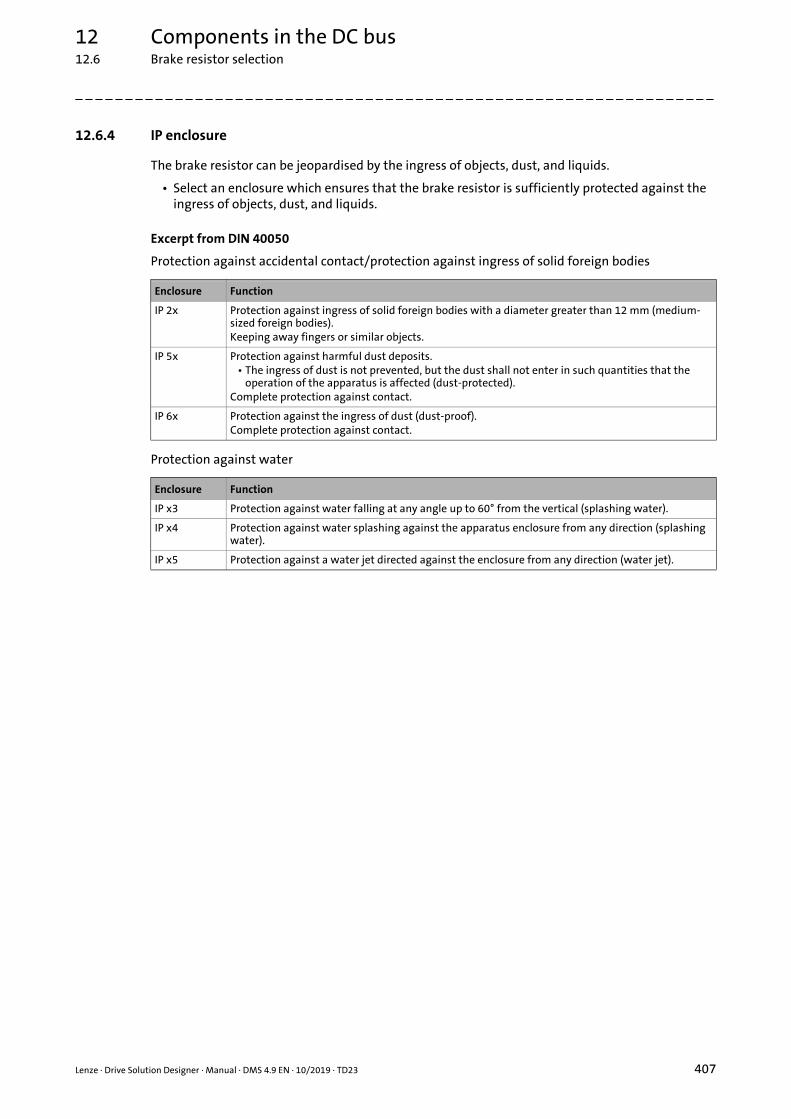
12 Components in the DC bus12.6 Brake resistor selection
_ _ _ _ _ _ _ _ _ _ _ _ _ _ _ _ _ _ _ _ _ _ _ _ _ _ _ _ _ _ _ _ _ _ _ _ _ _ _ _ _ _ _ _ _ _ _ _ _ _ _ _ _ _ _ _ _ _ _ _ _ _ _ _
12.6.4 IP enclosure
The brake resistor can be jeopardised by the ingress of objects, dust, and liquids.
• Select an enclosure which ensures that the brake resistor is sufficiently protected against the ingress of objects, dust, and liquids.
Excerpt from DIN 40050
Protection against accidental contact/protection against ingress of solid foreign bodies
Protection against water
Enclosure Function
IP 2x Protection against ingress of solid foreign bodies with a diameter greater than 12 mm (medium-sized foreign bodies).Keeping away fingers or similar objects.
IP 5x Protection against harmful dust deposits.• The ingress of dust is not prevented, but the dust shall not enter in such quantities that the
operation of the apparatus is affected (dust-protected).Complete protection against contact.
IP 6x Protection against the ingress of dust (dust-proof).Complete protection against contact.
Enclosure Function
IP x3 Protection against water falling at any angle up to 60° from the vertical (splashing water).
IP x4 Protection against water splashing against the apparatus enclosure from any direction (splashing water).
IP x5 Protection against a water jet directed against the enclosure from any direction (water jet).
Lenze · Drive Solution Designer · Manual · DMS 4.9 EN · 10/2019 · TD23 407

12 Components in the DC bus12.6 Brake resistor selection
_ _ _ _ _ _ _ _ _ _ _ _ _ _ _ _ _ _ _ _ _ _ _ _ _ _ _ _ _ _ _ _ _ _ _ _ _ _ _ _ _ _ _ _ _ _ _ _ _ _ _ _ _ _ _ _ _ _ _ _ _ _ _ _
12.6.5 Integrated brake transistor utilisation
12.6.5.1 Brake transistor in the inverter
The following inverters have an integrated brake transistor to which brake resistors can beconnected to.
• Servo Drives 9400 HighLine
• Inverter Drives 8400
• Inverter Drives 8400 protec
• Inverter Drives 8400 motec
The simulation of device-internal monitoring functions serves for the evaluation of the powerdemand by DSD and the determination of the utilisation of the brake transistor.
[12-4] Inverter diagram: utilisation of the integrated brake transistor
Description
Pgen(Pth,min) DC power in generator mode on the brake transistor, assuming ideal efficiency of motor, gearbox, and inverter.
Pgen(Pth,max) DC power in generator mode on the brake transistor, assuming worst efficiency of motor, gearbox, and inverter.
Pav,Brm Average braking power on the brake transistor, considering the thermal time constant (~th,Brm)
Pmax,Brm Peak braking power of the brake transistor
PN,Brm Continuous braking power of the brake transistor
Ath,Brm Thermal utilisation of the brake transistor.• Possible message: The permanent utilisation of the brake transistor is xxx %. Thus the limit
value of 100 % is exceeded.
ABrm(Pmax) Utilisation of the brake transistor relative to the peak braking power• Possible message: The max. utilisation of the brake chopper is xxx %. Thus the limit value of
100 % is exceeded.
~th,Brm Thermal time constant for checking the brake transistor
EDBrm Relative operating time of the brake resistor (pulse-pause ratio)
408 Lenze · Drive Solution Designer · Manual · DMS 4.9 EN · 10/2019 · TD23

12 Components in the DC bus12.6 Brake resistor selection
_ _ _ _ _ _ _ _ _ _ _ _ _ _ _ _ _ _ _ _ _ _ _ _ _ _ _ _ _ _ _ _ _ _ _ _ _ _ _ _ _ _ _ _ _ _ _ _ _ _ _ _ _ _ _ _ _ _ _ _ _ _ _ _
12.6.5.2 Brake transistor in the power supply module or regenerative power supply module
The following power supply modules and regenerative power supply modules have an integratedbrake transistor to which brake resistors can be connected to.
• Power supply module 9400
• 9400 regenerative power supply module
• i700 power supply module
The simulation of device-internal monitoring functions serves for the evaluation of the powerdemand by DSD and the determination of the utilisation of the power supply module orregenerative power supply module.
[12-5] Power supply module or regenerative power supply module diagram: integrated brake transistor utilisation
Description
Psum(t) Total power in generator mode in the DC bus over time
Pav,Brm Average braking power on the brake transistor, considering the thermal time constant (~th,Brm)
Pmax,Brm Peak braking power of the brake transistor
PN,Brm Continuous braking power of the brake transistor
Ath,Brm Thermal utilisation of the brake transistor.• Possible message: The permanent utilisation of the brake transistor is xxx %. Thus the limit
value of 100 % is exceeded.
ABrm(Pmax) Utilisation of the brake transistor relative to the peak braking power• Possible message: The max. utilisation of the brake chopper is xxx %. Thus the limit value of
100 % is exceeded.
~th,Brm Thermal time constant for checking the brake transistor
EDBrm Relative operating time of the brake resistor (pulse-pause ratio)
Lenze · Drive Solution Designer · Manual · DMS 4.9 EN · 10/2019 · TD23 409

12 Components in the DC bus12.6 Brake resistor selection
_ _ _ _ _ _ _ _ _ _ _ _ _ _ _ _ _ _ _ _ _ _ _ _ _ _ _ _ _ _ _ _ _ _ _ _ _ _ _ _ _ _ _ _ _ _ _ _ _ _ _ _ _ _ _ _ _ _ _ _ _ _ _ _
12.6.6 Brake resistor utilisation
The simulation of device-internal monitoring functions serves for the evaluation of the powerdemand by DSD and the determination of the utilisation of the brake resistor.
• Use brake resistors with a monitoring function (e.g. thermal contacts) to ensure that the mains contactor is switched off in the event of an overload.
12.6.6.1 Brake resistor on the inverter
The following inverters have an integrated brake transistor to which brake resistors can beconnected to.
• Servo Drives 9400 HighLine
• Inverter Drives 8400
• Inverter Drives 8400 protec
• Inverter Drives 8400 motec
The simulation of device-internal monitoring functions serves for the evaluation of the powerdemand by DSD and the determination of the utilisation of the brake resistor.
410 Lenze · Drive Solution Designer · Manual · DMS 4.9 EN · 10/2019 · TD23

12 Components in the DC bus12.6 Brake resistor selection
_ _ _ _ _ _ _ _ _ _ _ _ _ _ _ _ _ _ _ _ _ _ _ _ _ _ _ _ _ _ _ _ _ _ _ _ _ _ _ _ _ _ _ _ _ _ _ _ _ _ _ _ _ _ _ _ _ _ _ _ _ _ _ _
[12-6] Inverter diagram: brake resistor utilisation
Description
Pgen(Pth,min) DC power in generator mode on the brake resistor, assuming ideal efficiency of motor, inverter, and gearbox.
Pgen(Pth,max) DC power in generator mode on the brake resistor, assuming worst efficiency of motor, inverter, and gearbox.
Pav,Rb Average braking power on the brake resistor, considering the thermal time constant (~th,Brm)
PN,red Continuous power of the brake resistor
Pmax Peak power of the brake resistor
Amax,Rb Max. utilisation of the brake resistorPossible message: The max. utilisation of the equivalent resistance is xxx %. Thus the limit value of 100 % is exceeded.
Ath,Rb Thermal utilisation of the brake resistorPossible message: The permanent utilisation of the equivalent resistance is xxx %. Thus the limit value of 100 % is exceeded.
~th,Rb Thermal time constant for checking the brake resistor
Type Brake resistor type
Lenze · Drive Solution Designer · Manual · DMS 4.9 EN · 10/2019 · TD23 411

12 Components in the DC bus12.6 Brake resistor selection
_ _ _ _ _ _ _ _ _ _ _ _ _ _ _ _ _ _ _ _ _ _ _ _ _ _ _ _ _ _ _ _ _ _ _ _ _ _ _ _ _ _ _ _ _ _ _ _ _ _ _ _ _ _ _ _ _ _ _ _ _ _ _ _
12.6.6.2 Brake resistor on the power supply module or regenerative power supply module
The following power supply modules and regenerative power supply modules have an integratedbrake transistor to which brake resistors can be connected to.
• Power supply module 9400
• 9400 regenerative power supply module
• i700 power supply module
The simulation of device-internal monitoring functions serves for the evaluation of the powerdemand by DSD and the determination of the utilisation of the brake resistor.
[12-7] Power supply module or regenerative power supply module diagram: brake resistor utilisation
Description
Psum(t) Total power in generator mode in the DC bus over time
Pav,Rb Average braking power on the brake resistor, considering the thermal time constant (~th,Brm)
PN,red Continuous power of the brake resistor
Pmax Peak power of the brake resistor
Amax,Rb Max. utilisation of the brake resistorPossible message: The max. utilisation of the equivalent resistance is xxx %. Thus the limit value of 100 % is exceeded.
Ath,Rb Thermal utilisation of the brake resistorPossible message: The permanent utilisation of the equivalent resistance is xxx %. Thus the limit value of 100 % is exceeded.
~th,Rb Thermal time constant for checking the brake resistor
Type Brake resistor type
412 Lenze · Drive Solution Designer · Manual · DMS 4.9 EN · 10/2019 · TD23

Lenze · Drive Solution Designer · Manual · DMS 4.9 EN · 10/2019 · TD23 413
13 Product options
_ _ _ _ _ _ _ _ _ _ _ _ _ _ _ _ _ _ _ _ _ _ _ _ _ _ _ _ _ _ _ _ _ _ _ _ _ _ _ _ _ _ _ _ _ _ _ _ _ _ _ _ _ _ _ _ _ _ _ _ _ _ _ _
13 Product options
After drive dimensioning has been executed, you can select and configure in detail product optionsfor the motor, gearbox and inverter. These product options are required if an order is to begenerated from the dimensioning result.
• Features selected during the drive dimensioning process are permanently set in the product options and can only be changed in the corresponding dimensioning steps.
• In the case of non-configurable products (e.g. brake resistors), the product options shown are for information purposes only.
The “EASY Product Finder” product configuration is used as the central service for the productoptions so the Drive Solution Designer always uses the current product models. This means thatnew product options are available directly, for example, without having to update the DriveSolution Designer.
Configured product options are also saved if the Drive Solution Designer project is saved with theproduct configuration. After the Drive Solution Designer project is opened, the configured projectoptions are thus once again available. The configured product options can be overwritten if theDrive Solution Designer project is configured anew.
Tip!
Create an alternative project to retain the saved version of the product options. You canthen configure the Drive Solution Designer project and product options anew in thealternative.
Interaction between the Drive Solution Designer and the “EASY Product Finder”
After defining the product options in the Drive Solution Designer, save the shopping cart in a file.This file is now loaded to the “EASY Product Finder” shopping cart. You can now select furtherproducts for your project, store them in the shopping cart, and immediately send a request to LenzeSales, for example, to enquire price information and create CAD data.
Tip!
A wildcard is created in the shopping cart file for products that cannot be configured in theDrive Solution Designer. You can manually assign suitable products to the wildcards in the“EASY Product Finder”.
Configuration of the product options impossible
There may be a variety of reasons why the configuration is impossible.
Cause Possible remedies
Error transferring parameter values for the product configuration.
Contact Lenze sales partner.
No Internet connection. Check the Internet connection.
The “EASY Product Finder” server is not available at the moment due to maintenance work.
You may have to set the Internet address of a different server."Network connections" register ( 43)

14 Energy efficiency
_ _ _ _ _ _ _ _ _ _ _ _ _ _ _ _ _ _ _ _ _ _ _ _ _ _ _ _ _ _ _ _ _ _ _ _ _ _ _ _ _ _ _ _ _ _ _ _ _ _ _ _ _ _ _ _ _ _ _ _ _ _ _ _
14 Energy efficiency
Lenze BlueGreen solutions serve to execute energy efficiency calculations for dimensioned drives.
• A project comparison serves to compare and optimise the different mechanical concepts and drive components with regard to their energy required.
• You can calculate the share of energy in the production costs and the energy emissions for CO2 certificates of the European Union for the entire production line.
• Calculate the investment costs, cost schedules, cost rankings and the overall costs of the drive system.
• The results of the energy efficiency calculation are approximate values.• Contact the Lenze sales if you want to calculate the energy efficiency of the drive system
under real operating conditions.
• The energy efficiency calculation considers the most important losses in the drive system.• Considered loss sources: Application, gearbox, additional drive element, motor, inverter,
regenerative power supply module, brake chopper and brake resistors, DC-bus operation.• Losses of the following components are excepted: Engine fans, Motor fans, motor brakes,
filters, mains chokes, cables, additional modules of the inverter, automation components.• The losses of the application are based on the efficiency of the application entered in the DSD.
414 Lenze · Drive Solution Designer · Manual · DMS 4.9 EN · 10/2019 · TD23
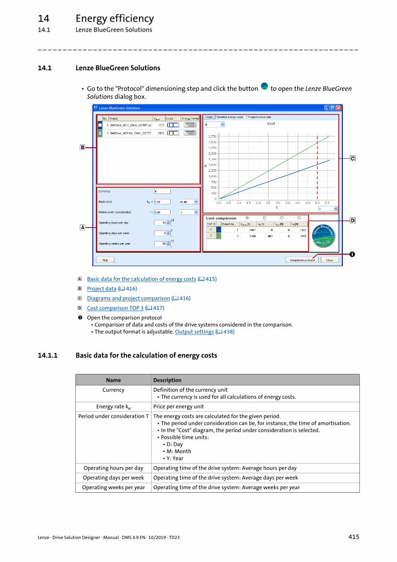
14 Energy efficiency14.1 Lenze BlueGreen Solutions
_ _ _ _ _ _ _ _ _ _ _ _ _ _ _ _ _ _ _ _ _ _ _ _ _ _ _ _ _ _ _ _ _ _ _ _ _ _ _ _ _ _ _ _ _ _ _ _ _ _ _ _ _ _ _ _ _ _ _ _ _ _ _ _
14.1 Lenze BlueGreen Solutions
• Go to the "Protocol" dimensioning step and click the button to open the Lenze BlueGreen Solutions dialog box.
14.1.1 Basic data for the calculation of energy costs
Basic data for the calculation of energy costs ( 415)
Project data ( 416)
Diagrams and project comparison ( 416)
Cost comparison TOP 3 ( 417)
Open the comparison protocol• Comparison of data and costs of the drive systems considered in the comparison.• The output format is adjustable. Output settings ( 438)
Name Description
Currency Definition of the currency unit• The currency is used for all calculations of energy costs.
Energy rate ke Price per energy unit
Period under consideration T The energy costs are calculated for the given period.• The period under consideration can be, for instance, the time of amortisation.• In the "Cost" diagram, the period under consideration is selected.• Possible time units:
• D: Day• M: Month• Y: Year
Operating hours per day Operating time of the drive system: Average hours per day
Operating days per week Operating time of the drive system: Average days per week
Operating weeks per year Operating time of the drive system: Average weeks per year
Lenze · Drive Solution Designer · Manual · DMS 4.9 EN · 10/2019 · TD23 415

14 Energy efficiency14.1 Lenze BlueGreen Solutions
_ _ _ _ _ _ _ _ _ _ _ _ _ _ _ _ _ _ _ _ _ _ _ _ _ _ _ _ _ _ _ _ _ _ _ _ _ _ _ _ _ _ _ _ _ _ _ _ _ _ _ _ _ _ _ _ _ _ _ _ _ _ _ _
14.1.2 Project data
14.1.3 Diagrams and project comparison
Name Description
Selection of the projects to be compared to each other.• Display of all projects that are currently opened in the DSD.• The project from which you have opened the Lenze BlueGreen Solutions, is a
reference project. It ranks first and cannot be deselected.• Remove the checkmark if you do not want to include the projects into the
comparison.• Each project is assigned to a colour. This makes it easy for you to detect it in the
cost diagram and while comparing costs.
No. Project number that are automatically assigned to the project.• DSD assigns the project number according to the sequence of the opened
projects.
Project Name of the project.• Indicates the file name of the DSD project.
Ksum Sum consists of energy costs KE (variable costs and investment costs Kext (fixed costs).
Costs Entering the investment costs Kext.• Press button to open the Price entry dialog box.• You can enter prices and possible discounts for components and
applications.• Accept the values. The Ksum column indicates the summarised costs.Investment costs of the drive components ( 419)
Energy Performance Certificate
Energy Performance Certificate of the drive system.• Press button to open the Energy Performance Certificate.• The output format is adjustable. Output settings ( 438) The Energy Performance Certificate ( 419)
Name Description
Cost Cost schedules as line diagram.• The amortisation date of the investment can be detected easily when all fixed
costs have been entered.• Note:
• The calculation is based on a constant utilisation of the machine.• Changes of the basic price are not taken into consideration.
Detailed energy costs Energy costs shown as bar diagram.• The energy costs of the drive system are shown as bars.• The energy costs of the components have different colours. This makes it easy for
you to detect the cost differentials.
Project comparison Representation of the data in tabular form.• Energy values and costs of the application and components can be compared
easily.
416 Lenze · Drive Solution Designer · Manual · DMS 4.9 EN · 10/2019 · TD23

14 Energy efficiency14.1 Lenze BlueGreen Solutions
_ _ _ _ _ _ _ _ _ _ _ _ _ _ _ _ _ _ _ _ _ _ _ _ _ _ _ _ _ _ _ _ _ _ _ _ _ _ _ _ _ _ _ _ _ _ _ _ _ _ _ _ _ _ _ _ _ _ _ _ _ _ _ _
Tabular project comparison
In addition to the graphic display, the tabular representation provides exact numerical values.
14.1.4 Cost comparison TOP 3
Name Description
TOP 3 Ranking of the drive systems according to different cost criteria.• The three projects that are shown in the list, depend on the selected cost
criterion.
Project no. Project number that are automatically assigned to the project.• DSD assigns the project number according to the sequence of the opened
projects.Project data ( 416)
Ksum Sum consists of energy costs KE (variable costs and investment costs Kext (fixed costs).Project data ( 416)
K Difference of the total costs Ksum of the projects.• The difference to the highest value in the list is displayed.
Kext Investment costs (fixed costs).Project data ( 416)
KE Energy costs (variable costs)Project data ( 416)
Sorting of the table according to a cost criterion.• Select the column with the costs you want to consider.
• The sorting is ascending, starting with the lowest costs.
Lenze · Drive Solution Designer · Manual · DMS 4.9 EN · 10/2019 · TD23 417

14 Energy efficiency14.1 Lenze BlueGreen Solutions
_ _ _ _ _ _ _ _ _ _ _ _ _ _ _ _ _ _ _ _ _ _ _ _ _ _ _ _ _ _ _ _ _ _ _ _ _ _ _ _ _ _ _ _ _ _ _ _ _ _ _ _ _ _ _ _ _ _ _ _ _ _ _ _
14.1.4.1 Detailed energy costs
The diagrams show the proportionate energy costs (losses) of the drive components available(gearbox, motor, inverter) and the application on the basis of the operating data entered and theenergy price. In this way, several drive solutions of different applications or alternative drivesolutions for identical applications can be graphically compared to each other.
[14-1] Proportionate energy costs of the drive components of one drive
[14-2] Comparison of the proportionate energy costs of the drive components of two drives
418 Lenze · Drive Solution Designer · Manual · DMS 4.9 EN · 10/2019 · TD23

14 Energy efficiency14.1 Lenze BlueGreen Solutions
_ _ _ _ _ _ _ _ _ _ _ _ _ _ _ _ _ _ _ _ _ _ _ _ _ _ _ _ _ _ _ _ _ _ _ _ _ _ _ _ _ _ _ _ _ _ _ _ _ _ _ _ _ _ _ _ _ _ _ _ _ _ _ _
14.1.4.2 Investment costs of the drive components
Use this dialog to optionally enter prices and discounts of the drive components. The prices areshown as investment costs in the "Cost schedule" diagram and provide some key decision criteriawith regard to amortisation.
[14-3] Entry of the investment costs of the drive components
14.1.5 The Energy Performance Certificate
The results of the energy efficiency calculation are documented in the Energy PerformanceCertificate:
• The Energy Performance Certificate contains detailed information on the required energy of the application, the different drive components, and of the drive system as a whole.
• The energy costs are displayed transparently and clearly.
• In addition, the recoverable energy is shown, which can be exchanged via the DC-bus or fed back into the supply system by means of a regenerative module.
• The CO2 emission according to the CO2 equivalent 550 g/kWh (source VDI) for the energy requirement and the recoverable energy is shown for the drive system as a whole.
• All results for the machine cycle (cycle time of the motion profile) and for the selected period under consideration (e. g. 5 years) are summed for the drive system as a whole.
• The energy requirement and the costs for the whole period under consideration are determined for the drive components and the application.
Lenze · Drive Solution Designer · Manual · DMS 4.9 EN · 10/2019 · TD23 419

14 Energy efficiency14.1 Lenze BlueGreen Solutions
_ _ _ _ _ _ _ _ _ _ _ _ _ _ _ _ _ _ _ _ _ _ _ _ _ _ _ _ _ _ _ _ _ _ _ _ _ _ _ _ _ _ _ _ _ _ _ _ _ _ _ _ _ _ _ _ _ _ _ _ _ _ _ _
14.1.6 Energy and power flows
The diagrams show the energy and loss characteristics of the drive components as a function oftime for one operating cycle. This example refers to a hoist drive.
• The energy efficiency diagrams can be found in the result tree under All diagrams.
[14-4] Energy and power characteristics of a hoist drive with acceleration and braking phases
Description
ET,I Energy characteristic at the inverter input (electrical energy)
ET,M Energ characteristic at the motor terminals (electrical energy)
ET,G Energy characteristic at the gearbox input (mechanical energy)
ET,App Energy characteristic at the application (mechanical energy)
ET,gen.sum Regenerative energy characteristic at the DC bus (electrical energy)
Psum,App Power loss characteristic of the application (mechanical power)
Pth,G Power loss characteristic of the gearbox (mechanical power)
Pth,M Power loss characteristic of the motor (electrical power)
Pth,I Power loss characteristic of the inverter (electrical power)
Psum,D Total power loss characteristic of the drive system
Pth,ave,G Average power loss of the gearbox (mechanical power)
Pth,ave,M Average power loss of the motor (electrical power)
Pth,ave,I Average power loss of the inverter (electrical power)
420 Lenze · Drive Solution Designer · Manual · DMS 4.9 EN · 10/2019 · TD23

14 Energy efficiency14.1 Lenze BlueGreen Solutions
_ _ _ _ _ _ _ _ _ _ _ _ _ _ _ _ _ _ _ _ _ _ _ _ _ _ _ _ _ _ _ _ _ _ _ _ _ _ _ _ _ _ _ _ _ _ _ _ _ _ _ _ _ _ _ _ _ _ _ _ _ _ _ _
14.1.7 Energy efficiency analysis with different load cycles
The DSD Energy Performance Certificate is based on repetitive operating cycles with identical loadprofiles. In practice, however, different scenarios and operating cycles (e.g. different motion profilesand variable payloads) are often executed at specific frequencies.
This chapter describes how an overall Energy Performance Certificate is compiled for differentscenarios.
If necessary, the total energy demand can be recorded later on by monitoring whilst the system isbeing operated and compared with the dimensioning in the DSD.
[14-5] Example: Operation with different load cycles
Example of an application with three different load cycles:
Frequency Operating scenario Scenario 1 Scenario 2 Scenario 3
DSD Fixed mass[kg]
Payload[kg]
Speed[m/s]
Service life[weeks/year]
Scenario project 1 500 300 1,2 10
Scenario project 2 500 210 0,8 15
Scenario project 3 500 100 0,5 25
Lenze · Drive Solution Designer · Manual · DMS 4.9 EN · 10/2019 · TD23 421

14 Energy efficiency14.1 Lenze BlueGreen Solutions
_ _ _ _ _ _ _ _ _ _ _ _ _ _ _ _ _ _ _ _ _ _ _ _ _ _ _ _ _ _ _ _ _ _ _ _ _ _ _ _ _ _ _ _ _ _ _ _ _ _ _ _ _ _ _ _ _ _ _ _ _ _ _ _
How to carry out the energy efficiency analysis:
1. Create a master project for the whole drive train and for all applicable operating modes.
2. Derive the scenario projects (1 ... n) from the master project in each case for the different operating scenarios.• The Application Tuner is a comfortable tool for carrying out the derivations.• The master project can also be used as scenario project.
3. In a last step, add the energy balances of all scenario projects manually.• For other analysis periods, the results must be converted proportionally.• Basic data for the calculation of energy costs ( 415)
[14-6] Procedure for compiling an Energy Performance Certificate with different load cycles
422 Lenze · Drive Solution Designer · Manual · DMS 4.9 EN · 10/2019 · TD23

14 Energy efficiency14.2 Tips for optimising the drive systems
_ _ _ _ _ _ _ _ _ _ _ _ _ _ _ _ _ _ _ _ _ _ _ _ _ _ _ _ _ _ _ _ _ _ _ _ _ _ _ _ _ _ _ _ _ _ _ _ _ _ _ _ _ _ _ _ _ _ _ _ _ _ _ _
14.2 Tips for optimising the drive systems
Generally the following applies:
• Avoid overdimensioning without extremely overloading the components.
• The longer the operating time of the drive, the greater are the saving effects.
Further possibilities for an energy-efficient dimensioning of the drive system can be found in thefollowing table.
Legend Possible dimensioning
Supply / feed• In DC-bus connection,• with power recovery into the mains.
Inverter with• servo control• low switching frequency,• 2-switch modulation (e.g. Inverter Drives 8400),• Control mode VFC plus eco.
Motor• Use synchronous motor, IE2 motor or 120-Hz motor• Utilise speed setting range, e. g. 87 Hz operation for standard motors
Gearbox with• a high efficiency,• a low number of stages,• a low input speed.
Application with• low friction,• low inertia.
Lenze · Drive Solution Designer · Manual · DMS 4.9 EN · 10/2019 · TD23 423

14En
ergy efficiency
14.2Tips for optim
ising th
e drive systems
424Len
ze · Drive Solu
tion D
esigner · M
anu
al · DM
S 4.9 EN · 10/2019 · TD
23
_ _ _ _ _ _ _ _ _ _ _ _ _ _ _ _ _ _ _ _ _ _ _ _ _ _ _ _ _ _ _ _ _ _ _ _ _ _ _ _ _ _ _ _ _ _ _ _ _ _ _ _ _ _ _ _ _ _ _ _ _ _ _ _
14.2.1 Cost-cutting potentials in applications
3. Using braking energy
Elec
tric
al d
rive
in
stea
d of
flu
id d
rive
DC
-bu
s co
nn
ecti
on f
or
ener
gy e
xch
ange
Bu
ffer
ing
the
brak
ing
ener
gy
(cap
acit
or)
Pow
er r
ecov
ery
into
th
e m
ain
s
1. Using electrical energy intelligently 2. Converting energy with high efficiency
Improved energy efficiency thanks to
Exac
t di
men
sion
ing
Clo
sed-
loop
con
trol
led
oper
atio
n
(inve
rter
)
Ener
gy-e
ffic
ien
t co
ntr
ol
Asy
nch
ron
ous
mot
or
wit
h h
igh
ef
fici
ency
Syn
chro
nou
s m
otor
Gea
rbox
wit
h h
igh
ef
fici
ency
Conveyor drive
Travelling drive
Hoist drive
Positioning drive
Coordinated drive for robots
Synchronous drive
Winding drive
Clock drive
Drive for electronic cam
Drive for forming process
Main or tool drive
Drive for pump or fan
Slider-crank mechanism, eccentric lift table
State of the technology
Great potential
Partial potential

14 Energy efficiency14.2 Tips for optimising the drive systems
_ _ _ _ _ _ _ _ _ _ _ _ _ _ _ _ _ _ _ _ _ _ _ _ _ _ _ _ _ _ _ _ _ _ _ _ _ _ _ _ _ _ _ _ _ _ _ _ _ _ _ _ _ _ _ _ _ _ _ _ _ _ _ _
14.2.2 Optimising the single-axis application
1. Dimension a drive axis in DSD.
2. Create an alternative of the DSD project and carry out the dimensioning with alternative drive components. Creating an alternative ( 55)
3. Compare both projects regarding the energy efficiency.• If required, check if changes of the motion profile have a positive effect on the energy
balance. Motion design ( 240)
14.2.3 Optimising the multi-axis application
4. Create the motion profiles for the drive axes in the independent MotionDesigner and optimise them with regard to realistic conditions so that as much energy as possible will be exchanged in the DC-bus connection. MotionDesigner ( 241)
5. Dimensioning drive axes in DSD.
6. Create one alternative each of the DSD projects and execute the dimensioning with alternative drive components. Creating an alternative ( 55)
7. Compare the projects regarding the energy efficiency.
8. Load the optimised DSD projects of the drive axes into the application "Dimensioning the multi-axis system" and configure the multi-axis system. Size the multi-axis system ( 186)
Lenze · Drive Solution Designer · Manual · DMS 4.9 EN · 10/2019 · TD23 425

14 Energy efficiency14.2 Tips for optimising the drive systems
_ _ _ _ _ _ _ _ _ _ _ _ _ _ _ _ _ _ _ _ _ _ _ _ _ _ _ _ _ _ _ _ _ _ _ _ _ _ _ _ _ _ _ _ _ _ _ _ _ _ _ _ _ _ _ _ _ _ _ _ _ _ _ _
14.2.4 Energy efficiency in a multi-axis system
In the multi-axis system, several inverters are actuated on the same DC bus. If this process involvestemporary or continuous regenerative actuation of some inverters, they directly exchange energiesin the DC bus without making any detours via the supply system. Regenerative operating phasescan for instance be generated by reducing a load (potential energy), by braking a drive to a standstill(kinetic energy), or by permanent braking of an unwinder (process energy). DC bus operation is avery efficient method to save electrical energy.
If some operating phases mainly involve regenerative energy, the use of a common brake chopperor a power supply module/regenerative module is additionally required. Without this measure, thedrives would become deenergised and therefore uncontrolled when there is excess regenerativeenergy.
[14-7] Energy flow in DC-bus operation
For a DC-bus connection, basically three electrical operating principles are provided to absorbregenerative energy and to therefore ensure continuous control of the drives:
Power supply module with brake chopper ( 427)
Power supply module/regenerative module without brake chopper ( 427)
Power supply module/regenerative module with brake chopper ( 428)
For the DC-bus connection, the DSD creates an Energy Performance Certificate for each drive axisand an Energy Performance Certificate for the power supply module.
Motoric energy
Regenerative energy
Energy exchanged in the DC bus
426 Lenze · Drive Solution Designer · Manual · DMS 4.9 EN · 10/2019 · TD23

14 Energy efficiency14.2 Tips for optimising the drive systems
_ _ _ _ _ _ _ _ _ _ _ _ _ _ _ _ _ _ _ _ _ _ _ _ _ _ _ _ _ _ _ _ _ _ _ _ _ _ _ _ _ _ _ _ _ _ _ _ _ _ _ _ _ _ _ _ _ _ _ _ _ _ _ _
[14-8] Energy costs in a DC-bus connection
14.2.4.1 Power supply module with brake chopper
If only a small amount of regenerative energy is produced, or if power recovery is not desired, acommon power supply module with an integrated brake chopper is used for all drives actuated inthe DC-bus connection. During the braking phases of the drive system, the excess regenerativeenergy is converted into thermal energy in a brake resistor.
14.2.4.2 Power supply module/regenerative module without brake chopper
If the whole regenerative energy is to be recovered by the supply system, a common regenerativepower supply module is used for all drives actuated in the DC-bus connection. During the brakingphases of the drive system, the excess regenerative energy is recovered by the supply system, andin this way the overall energy balance of the system is improved.
Supply via power supply module Supply via regenerative power supply module Energy converted into heat in the brake resistor Energy recovered into the supply system
Lenze · Drive Solution Designer · Manual · DMS 4.9 EN · 10/2019 · TD23 427

14 Energy efficiency14.2 Tips for optimising the drive systems
_ _ _ _ _ _ _ _ _ _ _ _ _ _ _ _ _ _ _ _ _ _ _ _ _ _ _ _ _ _ _ _ _ _ _ _ _ _ _ _ _ _ _ _ _ _ _ _ _ _ _ _ _ _ _ _ _ _ _ _ _ _ _ _
14.2.4.3 Power supply module/regenerative module with brake chopper
If the excess regenerative energy is to be recovered by the supply system and energy peaks areconverted into thermal energy in a brake resistor, a common regenerative power supply modulewith a brake resistor is used for all drives in the DC-bus connection. During the braking phases of thedrive system, the excess regenerative energy is recovered by the supply system first. If theregenerative module reaches the current limitation, the remaining regenerative energy is convertedin the brake resistor. This reduces the overall energy balance of a system.
Such hybrid concepts are applied if high, short-time, regenerative power peaks with a low energycontent occur, requiring a cost-effective concept. Also, a redundancy in the recovery concept for theevent of a mains failure may be desired.
428 Lenze · Drive Solution Designer · Manual · DMS 4.9 EN · 10/2019 · TD23

15 Results: comparing, optimising, logging
_ _ _ _ _ _ _ _ _ _ _ _ _ _ _ _ _ _ _ _ _ _ _ _ _ _ _ _ _ _ _ _ _ _ _ _ _ _ _ _ _ _ _ _ _ _ _ _ _ _ _ _ _ _ _ _ _ _ _ _ _ _ _ _
15 Results: comparing, optimising, logging
The DSD provides a variety of representations for evaluating results.
Drawing ( 430)
Reports ( 435)
Comparison and additional results ( 439)
Design data and transfer to the »EASY Product Finder« ( 440)
Results ( 434)
Lenze · Drive Solution Designer · Manual · DMS 4.9 EN · 10/2019 · TD23 429

15 Results: comparing, optimising, logging15.1 Drawing
_ _ _ _ _ _ _ _ _ _ _ _ _ _ _ _ _ _ _ _ _ _ _ _ _ _ _ _ _ _ _ _ _ _ _ _ _ _ _ _ _ _ _ _ _ _ _ _ _ _ _ _ _ _ _ _ _ _ _ _ _ _ _ _
15.1 Drawing
The drawing visualises the current state of the drive dimensioning.
Legend Description
Short overview of the drive system with the data entered, rated data of the selected drive components and their utilisation degrees, and display of notes and tips.
Illustration of the component (at the same time button).• By clicking on the illustration you directly reach the selection table for the corresponding
component where a variety of data is provided.
Button for calling messages for drive dimensioning of the corresponding component.
Button for calling the diagrams for the corresponding component.• Graphical representation of the speed, torque, and utilisation behaviour.Diagrams for the components ( 431)
Representation of the drive train used.
Button for calling the description of the application in the online help.
Button for calling the motion profile.Motion design ( 240)
430 Lenze · Drive Solution Designer · Manual · DMS 4.9 EN · 10/2019 · TD23

15 Results: comparing, optimising, logging15.1 Drawing
_ _ _ _ _ _ _ _ _ _ _ _ _ _ _ _ _ _ _ _ _ _ _ _ _ _ _ _ _ _ _ _ _ _ _ _ _ _ _ _ _ _ _ _ _ _ _ _ _ _ _ _ _ _ _ _ _ _ _ _ _ _ _ _
Diagrams for the components
In the Diagrams dialog box the speed, torque, and utilisation of the application or of a componentare shown in diagrams or value tables.
Legend Description
Buttons for switching the corresponding diagrams or value tables on/off.
Selection for the representation as diagrams or value tables.• The representation as diagram is a convenient help to assess the application or the component
and to identify reserves and possible risks.• The value table represents all values of a characteristic in the form of a table and thus facilitates
the determination of correct values (e. g. limit values) of the application or the component.• Where required, the limits for the respective components are also provided in the diagrams
displayed.
Lenze · Drive Solution Designer · Manual · DMS 4.9 EN · 10/2019 · TD23 431

15 Results: comparing, optimising, logging15.1 Drawing
_ _ _ _ _ _ _ _ _ _ _ _ _ _ _ _ _ _ _ _ _ _ _ _ _ _ _ _ _ _ _ _ _ _ _ _ _ _ _ _ _ _ _ _ _ _ _ _ _ _ _ _ _ _ _ _ _ _ _ _ _ _ _ _
Legend for the representation of the characteristics:
Buttons
Depending on the component, different quantities which can be individually shown or masked outby means of the following buttons on the upper edge of the profile dialog are shown in the profiledialog:
Graphics element Colour Kind Meaning
Point Blue Maximum operating point
Red Standstill point of the synchronous motor
Line Blue Requirement of the application
Red Maximum permissible values
Reduced rated values (temperature, height, etc.)
Max. continuous characteristics
Green Instantaneous PT1 function
Calculated equivalent values
Button Information
a Acceleration
Angular acceleration
BRK Setting the brake
CINH Setting the controller inhibit
fch Switching frequency of the inverter
fout Output frequency of the inverter
F Counterforce
F Tensile force at the belt
I Current within the motor, inverter
J Characteristic of mass inertia
m Characteristic of the payload mass
s Translatory traverse path
j Rotary traverse path
M Motor, gearbox, application torque
M, n Speed-torque characteristic of motor/gearbox
MBRK Torque curve of the holding brake
Mdyn Dynamic torque
Mout,G Output torque of the Lenze gearbox
Mout,K Output torque of the additional drive element
Msds Stationary torque
n Speed
nin,G Drive speed of the Lenze gearbox
nin,K Drive speed of the general ratio
432 Lenze · Drive Solution Designer · Manual · DMS 4.9 EN · 10/2019 · TD23

15 Results: comparing, optimising, logging15.1 Drawing
_ _ _ _ _ _ _ _ _ _ _ _ _ _ _ _ _ _ _ _ _ _ _ _ _ _ _ _ _ _ _ _ _ _ _ _ _ _ _ _ _ _ _ _ _ _ _ _ _ _ _ _ _ _ _ _ _ _ _ _ _ _ _ _
Editing functions
nout,G Output speed of the Lenze gearbox
nout,K Output speed of the additional drive element
Angular velocity
P Power, application, motor
PDC Required power in the DC bus
Preq Required power
% Thermal utilisation
TBRK Theoretical braking time of the mechanical brake• The time from the respective operating point until standstill is calculated
v Speed
Wl/t Characteristic of the gearbox fatique strength
E94APx Requirement calculation of the drive axis when the 9400 power supply module is used
E94ARx Requirement calculation of the drive axis when the 9400 regenerative power supply module is used
R Brake resistor
int.Chp Brake chopper integrated in the inverter
int.Chp 94 Brake chopper integrated in the 9400 power supply module or 9400 regenerative power supply module
Function Description
Zooming • Zooming in:• Draw up a rectangle across the area to be zoomed in by keeping the left mouse button pressed.
• Zooming out:• Open the context menu with the right mouse button. There are three commands for zooming
out under Automatic adjustment.
Copy Open the context menu with the right mouse button. Execute the Merge command to copy the diagram to clipboard.
Save as... Open the context menu with the right mouse button. Execute the Save as... command to save the diagram as PNG graphic (Portable Network Graphic).
Print... Open the context menu with the right mouse button. Execute the Print... command to open a dialog box which serves to print the diagram.
Button Information
Lenze · Drive Solution Designer · Manual · DMS 4.9 EN · 10/2019 · TD23 433

15 Results: comparing, optimising, logging15.2 Results
_ _ _ _ _ _ _ _ _ _ _ _ _ _ _ _ _ _ _ _ _ _ _ _ _ _ _ _ _ _ _ _ _ _ _ _ _ _ _ _ _ _ _ _ _ _ _ _ _ _ _ _ _ _ _ _ _ _ _ _ _ _ _ _
15.2 Results
The Result has a hierarchical tree structure and shows all results contained in the DSD:
• Diagrams of the application and the components
• Rated values and calculated values of the components
• Options of the components
Example: Representation of the rated values
• A in front of an element in the Result tree signals that subelements are available.
• If you click on , the subelements are shown.
• If you click on , the subelements are hidden.
• Different tabs in the result view show rated values, calculated values, or product options.
Example: Representation of a diagram (thermal inverter utilisation)
434 Lenze · Drive Solution Designer · Manual · DMS 4.9 EN · 10/2019 · TD23

15 Results: comparing, optimising, logging15.3 Reports
_ _ _ _ _ _ _ _ _ _ _ _ _ _ _ _ _ _ _ _ _ _ _ _ _ _ _ _ _ _ _ _ _ _ _ _ _ _ _ _ _ _ _ _ _ _ _ _ _ _ _ _ _ _ _ _ _ _ _ _ _ _ _ _
15.3 Reports
At the end of a dimensioning there are various possibilities of evaluating and documenting the drivesolution. You can create different protocols, compare several open projects to each other, and carryout a drive analysis. Protocols, analyses and project comparisons can either be opened in MicrosoftWord or Adobe Reader and be opened in addition.
Tip!
You can also log the current state of the dimensioning, compare open projects to eachother, or carry out a drive analysis anytime during the dimensioning process.
For this purpose, click the protocol button in the input area to open the protocol dialog box.
15.3.1 Summarised report
Note!
• The calculation results presented in the report are based on your default setting and the data you have entered.• Check whether these data are correct and complete. Lenze can not accept any
liability for incorrect, unusable, or incomplete drive solutions resulting from incorrect or incomplete data.
• The DSD carries out a physical drive dimensioning process. The specific properties and the operational performance of a drive cannot be taken into consideration.
• Since every application is individually integrated into an overall concept, we recommend having a system integration check performed by a Lenze specialist in addition to the drive dimensioning.
• Observe the Restrictions of the drive dimensioning section and the release notes in the "Application Knowledge Base" (AKB) at http://AKB.Lenze.de.
The summarised protocol is a summary of the most important data of the drivedimensioning and serves as an overview. The length of the protocol is one page.
• Click the icon to open the protocol.
• You can set the output format: Output settings ( 438)
Lenze · Drive Solution Designer · Manual · DMS 4.9 EN · 10/2019 · TD23 435

15 Results: comparing, optimising, logging15.3 Reports
_ _ _ _ _ _ _ _ _ _ _ _ _ _ _ _ _ _ _ _ _ _ _ _ _ _ _ _ _ _ _ _ _ _ _ _ _ _ _ _ _ _ _ _ _ _ _ _ _ _ _ _ _ _ _ _ _ _ _ _ _ _ _ _
15.3.2 Detailed report
15.3.3 Commissioning data
15.3.4 SAP list of the configuration
• The detailed protocol is the complete documentation of the drive dimensioning:• User and customer data• Notes• Application data• Rated data, utilisation values and options of the components selected• Warning signals• Dimensioning notes• A great number of diagrams and tables of values
• Click the icon to open the protocol.
• You can set the output format and information scope: Output settings ( 438)
• The commissioning data contain some specific information for the commissioning of the application:• User and customer data• Notes• Application data• Rated data, utilisation values and options of the components selected• Warning signals• Dimensioning notes• A great number of diagrams and tables of values
• Click the icon to open the protocol.
• You can set the output format and information scope: Output settings ( 438)
The list shows the features of the Lenze products used, which are required for atransfer to the »EASY Product Finder«.
• Click the icon to open the SAP list.• The dialog box can also be opened using the ViewProduct options for
EASY Product Finder / SAP command.
436 Lenze · Drive Solution Designer · Manual · DMS 4.9 EN · 10/2019 · TD23

15 Results: comparing, optimising, logging15.3 Reports
_ _ _ _ _ _ _ _ _ _ _ _ _ _ _ _ _ _ _ _ _ _ _ _ _ _ _ _ _ _ _ _ _ _ _ _ _ _ _ _ _ _ _ _ _ _ _ _ _ _ _ _ _ _ _ _ _ _ _ _ _ _ _ _
Lenze · Drive Solution Designer · Manual · DMS 4.9 EN · 10/2019 · TD23 437

15 Results: comparing, optimising, logging15.3 Reports
_ _ _ _ _ _ _ _ _ _ _ _ _ _ _ _ _ _ _ _ _ _ _ _ _ _ _ _ _ _ _ _ _ _ _ _ _ _ _ _ _ _ _ _ _ _ _ _ _ _ _ _ _ _ _ _ _ _ _ _ _ _ _ _
15.3.5 Output settings
In the settings for the protocol you define the format and the length.
• Click the icon to open the dialog box.• The dialog box can also be opened via ToolsSettings, Protocol tab.• Settings ( 42)
• Available formats for all versions:• Doc (from Microsoft Word 2002)• WordML (from Microsoft Word 2003, Service Pack 2)• PDF (Adobe Reader)
• Details for the detailed protocol and the commissioning data• Detailed selection of diagrams and value tables.
438 Lenze · Drive Solution Designer · Manual · DMS 4.9 EN · 10/2019 · TD23

15 Results: comparing, optimising, logging15.4 Comparison and additional results
_ _ _ _ _ _ _ _ _ _ _ _ _ _ _ _ _ _ _ _ _ _ _ _ _ _ _ _ _ _ _ _ _ _ _ _ _ _ _ _ _ _ _ _ _ _ _ _ _ _ _ _ _ _ _ _ _ _ _ _ _ _ _ _
15.4 Comparison and additional results
15.4.1 Application Tuner
15.4.2 Comparison of the open projects
15.4.3 BlueGreen
The Application Tuner serves to
• change the data of the application and the motion data as well as to observe and optimise the impacts on the drive,
• integrate further possible operating statuses and material recipes into the dimensioning for the reference scenario,
• create your own DSD project based on an optimised drive solution or to output a protocol.
Click the icon to open the Application Tuner dialog box.
Application Tuner ( 57)
If several projects are open at the same time, they can be compared with respectto the application and the utilisation of the components.
• Click the icon to open the project comparison.• The dialog box can also be opened with the command ViewProject
comparison.• Project comparison ( 59)
Lenze · Drive Solution Designer · Manual · DMS 4.9 EN · 10/2019 · TD23 439

15 Results: comparing, optimising, logging15.5 Design data and transfer to the »EASY Product Finder«
_ _ _ _ _ _ _ _ _ _ _ _ _ _ _ _ _ _ _ _ _ _ _ _ _ _ _ _ _ _ _ _ _ _ _ _ _ _ _ _ _ _ _ _ _ _ _ _ _ _ _ _ _ _ _ _ _ _ _ _ _ _ _ _
Solutions
15.5 Design data and transfer to the »EASY Product Finder«
15.5.1 CAD data in the geared motor
15.5.2 CAD datainverter
The different mechanical concepts and drive components can be compared andoptimised with regard to the energy required.
• Click the icon to open the Lenze BlueGreen Solutions dialog box.
Energy efficiency ( 414)
If product characteristics have been defined in the Details regarding Lenzeproducts dimensioning step, you can generate the engineering data of the gearedmotor.
• This function requires an Internet connection.
• CAD data are not available for all components.
• Click the icon to generate the construction data.
If product characteristics have been defined in the Details regarding Lenzeproducts dimensioning step, you can generate the engineering data of theinverter.
• This function requires an Internet connection.
• CAD data are not available for all components.
• Click the icon to generate the construction data.
440 Lenze · Drive Solution Designer · Manual · DMS 4.9 EN · 10/2019 · TD23

15 Results: comparing, optimising, logging15.5 Design data and transfer to the »EASY Product Finder«
_ _ _ _ _ _ _ _ _ _ _ _ _ _ _ _ _ _ _ _ _ _ _ _ _ _ _ _ _ _ _ _ _ _ _ _ _ _ _ _ _ _ _ _ _ _ _ _ _ _ _ _ _ _ _ _ _ _ _ _ _ _ _ _
15.5.3 Shopping cart for »EASY Product Finder«
Projects can be stored in a shopping cart and then loaded to the shopping cart ofthe »EASY Product Finder«. This requires the configuration of the product options.
Product options ( 413)
• In addition to the products used in the project, also project information items are stored:• File name of the project• DSD version• Project• Date of creation• Date of the last change• Drive axis
• The Shopping cart for »EASY Product Finder« function requires a connection with the Internet. If necessary, the URL can be set under ExtrasSettings in the Network connections area in the URL for product configuration field."Network connections" register ( 43)
• Storing the current DSD project in a shopping cart file:• Click on the shopping cart item.
• Storing all projects opened in the DSD in a shopping cart file:• Execute the Save all DSD projects in the shopping cart... command in the
Tools menu, or
• click on the icon in the toolbar.
• Loading the shopping cart file in the »EASY Product Finder«:• Execute the Load shopping cart file command in the shopping cart of the
»EASY Product Finder«, select the shopping cart file of the DSD saved locally and load it.
Note!
For products that cannot be configured in the DSD, a wildcard is createdin the shopping cart file. In the »EASY Product Finder« you can manuallyassign suitable products to the wildcards. If you have any questionsregarding the product selection, please refer to your Lenze sales partner.
Lenze · Drive Solution Designer · Manual · DMS 4.9 EN · 10/2019 · TD23 441

15 Results: comparing, optimising, logging15.6 Reserves with regard to the drive dimensioning
_ _ _ _ _ _ _ _ _ _ _ _ _ _ _ _ _ _ _ _ _ _ _ _ _ _ _ _ _ _ _ _ _ _ _ _ _ _ _ _ _ _ _ _ _ _ _ _ _ _ _ _ _ _ _ _ _ _ _ _ _ _ _ _
15.6 Reserves with regard to the drive dimensioning
In order to avoid a multiple consideration of reserves, no reserves whatsoever are allowed for in theDSD (exception: DC bus power in the multi-axis grouping).
• The DSD supports the decision-making with regard to the reserves by displaying all utilisation degrees. However, you have to decide for yourself whether a smaller component (inverter, motor, or gearbox) still suffices.
• In order to avoid a selection of reserves that are too big, it usually is assumed that the system planner has also already provided for reserves without explicitly mentioning this.
15.6.1 Dynamic reserves
These are reserves of the inverter-motor combination with regard to the torque.
• The dynamic reserves should at least be 15 ... 25 %, so that the drive can always be controlled in a safe manner.
15.6.2 Stationary reserves
These are reserves for the rated point of the drive component, i. e. usually thermal reserves.
• The stationary reserves can turn out slightly smaller than the dynamic reserves. There are applications which can be operated with a thermal reserve of the motor of 0 %.
• Recommended values: 5 ... 15 %, depending on the application and safety relevance.
Note!
Generally, sufficient reserves are to be provided for with regard to drive dimensionings, so that:• the application is always under control (inverter may not run in current limitation),
and the drive does not become uncontrollable if there are slight changes with regard to the load or to sluggishness.
• the drive is not operated above its rated data thermally and with regard to its service life (this particularly applies to gearboxes).
Of course, on the other hand, the reserves should not be too big, because after all this is a competitive factor possibly resulting in unacceptable price/performance ratios.
With regard to the amount of the reserves, note the comments in the following subchapters!
442 Lenze · Drive Solution Designer · Manual · DMS 4.9 EN · 10/2019 · TD23

15 Results: comparing, optimising, logging15.6 Reserves with regard to the drive dimensioning
_ _ _ _ _ _ _ _ _ _ _ _ _ _ _ _ _ _ _ _ _ _ _ _ _ _ _ _ _ _ _ _ _ _ _ _ _ _ _ _ _ _ _ _ _ _ _ _ _ _ _ _ _ _ _ _ _ _ _ _ _ _ _ _
15.6.3 Speed reserves
If unlimited performance of the application is also required in the case of undervoltages, voltagedrops due to long motor cables, or filters, corresponding speed reserves must be considered in thedrive dimensioning.
15.6.4 Torque reserves of the motor
Dynamic torque reserves can only be accurately planned by using the M-n characteristics of themotor.
• In the selection table of the motor the requirement of the application is represented in the M-n characteristic. Selection table ( 337)
15.6.5 Reserves for inverters, power supply modules, regenerative power supply modules
These are reserves for the maximum current Imax and the thermal utilisation "ixt" of the inverter.
• The Imax reserves should at least be 15 ... 25 %, so that the drive can always be controlled in a safe manner.
• The ixt reserves should at least be 15 ... 25 %, so that the drive works reliably and does not switch off.
Note!
Note that the dimensioning of this drive component defines the braking ability of the drive train and should not be dimensioned too tightly.
With regard to the determined DC power, the DSD already allows for 10 % of reserves, and also represents it as a requirement (incl. reserves).
Lenze · Drive Solution Designer · Manual · DMS 4.9 EN · 10/2019 · TD23 443

15 Results: comparing, optimising, logging15.6 Reserves with regard to the drive dimensioning
_ _ _ _ _ _ _ _ _ _ _ _ _ _ _ _ _ _ _ _ _ _ _ _ _ _ _ _ _ _ _ _ _ _ _ _ _ _ _ _ _ _ _ _ _ _ _ _ _ _ _ _ _ _ _ _ _ _ _ _ _ _ _ _
15.6.6 Reserves for brake resistors and brake choppers
Brake resistors are non-critical components, so that they don't immediately fail or are switched offif the rated power is exceeded.
• If the rated power of the resistor is exceeded continuously, the temperature monitoring of the resistor can be activated and switch off the system.
The brake choppers do not feature a current monitoring.
• The maximum permissible current can be exceeded by an incorrect assignment of the brake resistor, which, however, is checked by the DSD.
• The continuous load limit of the brake chopper is also checked by the DSD.
Danger!
Without a temperature monitoring on the resistor, the surface temperature can reach impermissible values and possibly present an ignition source for combustible materials close-by!
Note!
Note that the dimensioning of this drive component defines the braking ability of the drive train and should not be dimensioned too tightly.
With regard to the determined DC power, the DSD already allows for 10 % of reserves, and also represents it as a requirement (incl. reserves).
The reserves for brake resistors/brake choppers should be at least 15 ... 25 %.
444 Lenze · Drive Solution Designer · Manual · DMS 4.9 EN · 10/2019 · TD23

15 Results: comparing, optimising, logging15.6 Reserves with regard to the drive dimensioning
_ _ _ _ _ _ _ _ _ _ _ _ _ _ _ _ _ _ _ _ _ _ _ _ _ _ _ _ _ _ _ _ _ _ _ _ _ _ _ _ _ _ _ _ _ _ _ _ _ _ _ _ _ _ _ _ _ _ _ _ _ _ _ _
15.6.7 Reserves for gearboxes
Rated torque Mper,out at the gearbox output end
An occasional and short-time exceeding of the rated torque Mper,out is initially non-critical if themaximum value < 2 × Mper,out (planetary gearbox: < 1.6 × Mper,out).
• However, if this happens repeatedly, the gearbox is operated in fatique strength and the service life of the gearbox is reduced.
• In case of a gearbox, except for planetary gearboxes, the alternating load factor kalt has to be considered. Alternating load and repeated load cycle with regard to toothed gearboxes ( 372)
• The maximum value of 2 × Mper,out (planetary gearbox: 1.6 × Mper,out) should by no means be exceeded (even if it only occurs occasionally) as the service life of the gearbox will be reduced considerably.
Average input speed (thermal limit)
Exceeding the thermal limit leads to increased stress of gaskets and lubricant, which results in areduction of the useful life.
Maximum drive speed
This value is above the average input speed. Exceeding the max. permissible input speed leads to anextremely high and damaging stress of gaskets and lubricant, which causes a significant reductionof the useful life.
Stop!
Any operation in the range of the fatique strength affects the gearbox!
If accordingly high load cycle numbers are reached, massive damage, for example tooth or shaft breaks is possible!
Check of the torque load ( 370)
Lenze · Drive Solution Designer · Manual · DMS 4.9 EN · 10/2019 · TD23 445

15 Results: comparing, optimising, logging15.6 Reserves with regard to the drive dimensioning
_ _ _ _ _ _ _ _ _ _ _ _ _ _ _ _ _ _ _ _ _ _ _ _ _ _ _ _ _ _ _ _ _ _ _ _ _ _ _ _ _ _ _ _ _ _ _ _ _ _ _ _ _ _ _ _ _ _ _ _ _ _ _ _
15.6.8 Reserves for drive systems with an active load
The value to be set with regard to the dynamic reserves for drive systems with an active load (e. g.hoists or vertical conveyors) must not be too small, because for example hoists in the range ofcurrent limitation move downwards.
In DSD, motor brakes are only dimensioned as holding brakes, not as service brakes. Additionalchecks must be carried out manually. Notes with regard to this subject are included in the DSDprotocol. The use of PM brakes must also be checked in the case of winding applications.
In the case of hoist drives (e.g. cable-guided hoists, vertical lifters via toothed belts, racks andpinions), please observe that permanent magnet holding brakes
• have a significant speed-dependent torque drop which may vary from 100 % of the characteristic braking torque at zero speed to 20 % of the characteristic braking torque.
• cannot safety brake the drive in the lowering phase if the electrical braking via the inverters fails. Hence, these brakes are not suitable for emergency braking. Use an additional (redundant) brake outside of the motor or a spring-applied brake.
15.6.9 Reserves for drive systems with a passive load
These applications are not so critical with regard to dynamic reserves like those for hoists or verticalconveyors.
• In order to continuously operate motion applications with a low positioning error, the dynamic reserves here also are to be at least 15 ... 25 %.
• Motor brakes do not have to have greater reserves for these applications, actually they may even be smaller than the rated motor torque.
Note!
With regard to a hoist, at least 100 % of reserve should be provided for the dimensioning of the motor brake!
446 Lenze · Drive Solution Designer · Manual · DMS 4.9 EN · 10/2019 · TD23

16 Manage user motors
_ _ _ _ _ _ _ _ _ _ _ _ _ _ _ _ _ _ _ _ _ _ _ _ _ _ _ _ _ _ _ _ _ _ _ _ _ _ _ _ _ _ _ _ _ _ _ _ _ _ _ _ _ _ _ _ _ _ _ _ _ _ _ _
16 Manage user motors
User motors are required for drive dimensioning if
• motors required are not available in the Lenze product range (e.g. in the power range from 90 kW to 315 kW),
• Lenze motors are to be actuated with other type data, e.g. 29-Hz motors (some 29-Hz motors are already included in the user motor database in the DSD),
• new Lenze motors are not yet included in the DSD,
• special motors are required for solving the application.
The Manage user motors function serves to work with user-defined motors in the DSD.
Features of user motors in the DSD
• Three-phase AC motors, asynchronous servo motors and synchronous servo motors can be created individually.
• During drive dimensioning, user motors can be selected the same way as Lenze motors.
• The coupling with Lenze gearboxes is made via flange mounting.
• Drive dimensioning with feedback system and electromechanical brake is possible. The user motor can be defined with these components.
• Some Lenze motors have already been created in 29-Hz technology by default. These motors are preferably used for winding drives.
• User motors in DSD projects of other users can be imported to DSD when the project is opened.
Click the icon in the toolbar of the DSD or select the Tools Manage user motors... command to open the Manage user motors dialog box.
Lenze · Drive Solution Designer · Manual · DMS 4.9 EN · 10/2019 · TD23 447

16 Manage user motors16.1 User interface
_ _ _ _ _ _ _ _ _ _ _ _ _ _ _ _ _ _ _ _ _ _ _ _ _ _ _ _ _ _ _ _ _ _ _ _ _ _ _ _ _ _ _ _ _ _ _ _ _ _ _ _ _ _ _ _ _ _ _ _ _ _ _ _
16.1 User interface
Legend
Toolbar ( 449)
Management area ( 449)
Input area ( 450)
448 Lenze · Drive Solution Designer · Manual · DMS 4.9 EN · 10/2019 · TD23

16 Manage user motors16.2 Toolbar
_ _ _ _ _ _ _ _ _ _ _ _ _ _ _ _ _ _ _ _ _ _ _ _ _ _ _ _ _ _ _ _ _ _ _ _ _ _ _ _ _ _ _ _ _ _ _ _ _ _ _ _ _ _ _ _ _ _ _ _ _ _ _ _
16.2 Toolbar
Click on an icon to carry out the respective function.
16.3 Management area
Display
Symbol Function
Create a new user motor.• Creates a new data set.
Save data set of the marked user motor.
Save data sets of all user motors.
Delete marked user motor.
Export all data sets of the self-created user motors.• The data sets can be transmitted to other DSD installations.• The data sets of the supplied user motors cannot be exported.• The data sets have the file format *.mdb (Microsoft Access).
Import data sets of self-created user motors that have been created in a different DSD installation.• The data sets have the file format *.mdb (Microsoft Access).
Display Meaning
Group Motor designation• The designation serves the purpose of documentation and has no impact on the tests performed by
the DSD.• The motor designation is shown in the selection table of the motor in the Group column. Selection
table ( 337)
Type Motor type• The designation serves the purpose of documentation and has no impact on the tests performed by
the DSD.• The motor type is shown in the selection table of the motor in the Type column. Selection table
( 337)
Status The data set of the user motor contains changes that have not been saved yet.• Save data set via the command in the toolbar or in the context menu.•
All data of the user motor are saved in the data set.
The data of the user motor is not complete.• The imported data of the user motor comes from an elder DSD version where less data was
required for creating a user motor.• Complete data in order that the display goes off.
Lenze · Drive Solution Designer · Manual · DMS 4.9 EN · 10/2019 · TD23 449
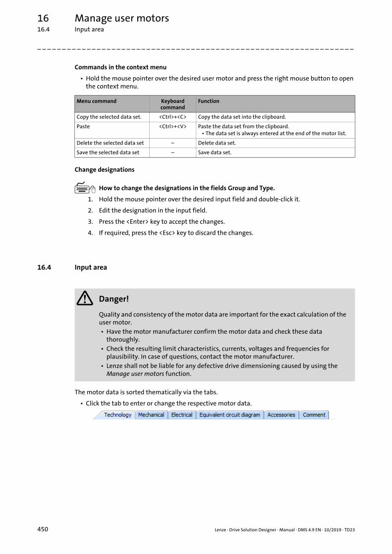
16 Manage user motors16.4 Input area
_ _ _ _ _ _ _ _ _ _ _ _ _ _ _ _ _ _ _ _ _ _ _ _ _ _ _ _ _ _ _ _ _ _ _ _ _ _ _ _ _ _ _ _ _ _ _ _ _ _ _ _ _ _ _ _ _ _ _ _ _ _ _ _
Commands in the context menu
• Hold the mouse pointer over the desired user motor and press the right mouse button to open the context menu.
Change designations
How to change the designations in the fields Group and Type.
1. Hold the mouse pointer over the desired input field and double-click it.
2. Edit the designation in the input field.
3. Press the <Enter> key to accept the changes.
4. If required, press the <Esc> key to discard the changes.
16.4 Input area
The motor data is sorted thematically via the tabs.
• Click the tab to enter or change the respective motor data.
Menu command Keyboard command
Function
Copy the selected data set. <Ctrl>+<C> Copy the data set into the clipboard.
Paste <Ctrl>+<V> Paste the data set from the clipboard.• The data set is always entered at the end of the motor list.
Delete the selected data set – Delete data set.
Save the selected data set – Save data set.
Danger!
Quality and consistency of the motor data are important for the exact calculation of the user motor.• Have the motor manufacturer confirm the motor data and check these data
thoroughly.• Check the resulting limit characteristics, currents, voltages and frequencies for
plausibility. In case of questions, contact the motor manufacturer.• Lenze shall not be liable for any defective drive dimensioning caused by using the
Manage user motors function.
450 Lenze · Drive Solution Designer · Manual · DMS 4.9 EN · 10/2019 · TD23

16 Manage user motors16.4 Input area
_ _ _ _ _ _ _ _ _ _ _ _ _ _ _ _ _ _ _ _ _ _ _ _ _ _ _ _ _ _ _ _ _ _ _ _ _ _ _ _ _ _ _ _ _ _ _ _ _ _ _ _ _ _ _ _ _ _ _ _ _ _ _ _
16.4.1 "Technology" tab
Parameter Symbol Description Dimension unit
Motor technology Type Motor type selection:• Asynch. servo motor• Synchronous servo motor• Three-phase AC motor
Standard – Standard for mounting the motor to the gearbox:• IEC 72, DIN 42948• NEMA• No standard
Operating voltage Uopr,D Supply system voltage• Input voltage of the inverter
V
Number of phases – Only user motors for 3-phase mains connection can be created.
• Read only.
Enclosure IP Protection type of the motor
IP 23 Protection against solid particles with 12.5 mm and falling spraying water up to 60° against the vertical
IP 54 Protection against a damaging amount of dust and splash water from all sides
IP XX To be selected if the motor does not fulfil IP 23 or IP 54
Cooling – Select cooling mode of the motor
S Naturally ventilated, no fanPreferred values for derating: n11 = 0, M11 = M0
E, G Self-ventilated, the fan is mounted on the motor shaft (G: Cast iron fan for increased inertia)
• The cooling effect decreases at low speeds
• Give values for derating the torque under n11 and M11
F Forced ventilated, the fan is mounted on the motor
• Preferred values for derating: n11 = 0, M11 = M0
M0, M11, n11: "Mechanical" tab ( 452)
Number of pole pairs, motor
– Number of motor pole pairs:• 2-pole motor: p = 1• 4-pole motor: p = 2• 6-pole motor: p = 3
Lenze · Drive Solution Designer · Manual · DMS 4.9 EN · 10/2019 · TD23 451
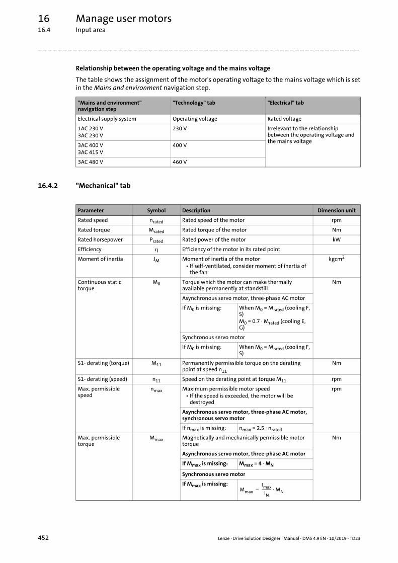
16 Manage user motors16.4 Input area
_ _ _ _ _ _ _ _ _ _ _ _ _ _ _ _ _ _ _ _ _ _ _ _ _ _ _ _ _ _ _ _ _ _ _ _ _ _ _ _ _ _ _ _ _ _ _ _ _ _ _ _ _ _ _ _ _ _ _ _ _ _ _ _
Relationship between the operating voltage and the mains voltage
The table shows the assignment of the motor's operating voltage to the mains voltage which is setin the Mains and environment navigation step.
16.4.2 "Mechanical" tab
"Mains and environment"navigation step
"Technology" tab "Electrical" tab
Electrical supply system Operating voltage Rated voltage
1AC 230 V3AC 230 V
230 V Irrelevant to the relationship between the operating voltage and the mains voltage
3AC 400 V3AC 415 V
400 V
3AC 480 V 460 V
Parameter Symbol Description Dimension unit
Rated speed nrated Rated speed of the motor rpm
Rated torque Mrated Rated torque of the motor Nm
Rated horsepower Prated Rated power of the motor kW
Efficiency Efficiency of the motor in its rated point
Moment of inertia JM Moment of inertia of the motor• If self-ventilated, consider moment of inertia of
the fan
kgcm2
Continuous static torque
M0 Torque which the motor can make thermally available permanently at standstill
Nm
Asynchronous servo motor, three-phase AC motor
If M0 is missing: When M0 = Mrated (cooling F, S)M0 = 0.7 Mrated (cooling E, G)
Synchronous servo motor
If M0 is missing: When M0 = Mrated (cooling F, S)
S1- derating (torque) M11 Permanently permissible torque on the derating point at speed n11
Nm
S1- derating (speed) n11 Speed on the derating point at torque M11 rpm
Max. permissible speed
nmax Maximum permissible motor speed• If the speed is exceeded, the motor will be
destroyed
rpm
Asynchronous servo motor, three-phase AC motor, synchronous servo motor
If nmax is missing: nmax = 2.5 nrated
Max. permissible torque
Mmax Magnetically and mechanically permissible motor torque
Nm
Asynchronous servo motor, three-phase AC motor
If Mmax is missing: Mmax = 4 MN
Synchronous servo motor
If Mmax is missing:Mmax
Imax
IN----------- MN=
452 Lenze · Drive Solution Designer · Manual · DMS 4.9 EN · 10/2019 · TD23

16 Manage user motors16.4 Input area
_ _ _ _ _ _ _ _ _ _ _ _ _ _ _ _ _ _ _ _ _ _ _ _ _ _ _ _ _ _ _ _ _ _ _ _ _ _ _ _ _ _ _ _ _ _ _ _ _ _ _ _ _ _ _ _ _ _ _ _ _ _ _ _
Torque/speed characteristic
DSD calculates the M/n characteristic on the basis of the entered motor data and the selectedinverter.
[16-1] Plausible M/n characteristic of a user motor (asynchronous motor)
Continuous standstill torque M0
Derating pointPermanently permissible torque M11 at speed n11
Rated pointRated torque Mrated and rated speed nrated
Equivalent characteristic
S1 characteristic
Lenze · Drive Solution Designer · Manual · DMS 4.9 EN · 10/2019 · TD23 453

16 Manage user motors16.4 Input area
_ _ _ _ _ _ _ _ _ _ _ _ _ _ _ _ _ _ _ _ _ _ _ _ _ _ _ _ _ _ _ _ _ _ _ _ _ _ _ _ _ _ _ _ _ _ _ _ _ _ _ _ _ _ _ _ _ _ _ _ _ _ _ _
16.4.3 "Electrical" tab
Parameter Symbol Description Dimension unit
Rated current Irated Current of the motor in its rated point A
Standstill current I0 Permanently permissible motor current at standstill• The value is not checked
A
Asynchronous servo motor, three-phase AC motor, synchronous servo motor
If I0 is missing: I0 = Irated
Max. permissible current
Imax Max. permissible motor current A
Only asynchronous servo motor, three-phase AC motor
If Imax is missing: Imax = 4 Irated
Rated voltage Urated Rated voltage of the motor• When the motor is connected to the inverter, the
motor voltage may be lower than the rated voltage. This might cause a change of the motor performance data.
V
Wiring – Selection of the wiring of the motor windings
Y Star connection
Delta connection
Rated frequency frated Field frequency for the respective rated point Hz
Power factor cos Power factor in the rated operation
454 Lenze · Drive Solution Designer · Manual · DMS 4.9 EN · 10/2019 · TD23

16 Manage user motors16.4 Input area
_ _ _ _ _ _ _ _ _ _ _ _ _ _ _ _ _ _ _ _ _ _ _ _ _ _ _ _ _ _ _ _ _ _ _ _ _ _ _ _ _ _ _ _ _ _ _ _ _ _ _ _ _ _ _ _ _ _ _ _ _ _ _ _
16.4.4 "Equivalent circuit diagram" tab
16.4.4.1 Asynchronous servo motor, three-phase AC motor
• Enter the value for a motor phase. DSD calculates with the equivalent circuit diagram of a motor phase.
• If Lenze three-phase AC motors (MD, MH, MF) and Lenze asynchronous servo motors (MCA, MQA) are listed in the Lenze parameter C00086, you can use the values from the motor table in the »Engineer«.
• The value for the iron loss resistance RFE is not contained in C00086. The data is optional.
• If no checked value is provided, always enter zero. Otherwise, a wrong characteristic occurs.
• Provide the resistance values R1 and R2’ for an operating temperature of 20 °C.
If operating temperatures are specified according to EN 60085 in classes of insulation, the resistance values have to be converted for an operating temperature of 20 °C. Guide values for classes of insulation are: Class B = 120 °C, class F = 150 °C. Ask the motor manufacturer for the exact values.
Parameter Symbol Description Dimension unit
Stator resistance R1 Resistance value of the stator winding• Give value for an operating temperature of 20 °C
Rotor resistance R2’ Resistance value of the rotor winding, with regard to the stator end
• Give value for an operating temperature of 20 °C
Mutual inductance Lh Mutual inductance at rated operation mH
Stator leakage inductance
L1s Leakage inductance of the stator mH
Rotor leakage inductance
L2s’ Leakage inductance of the rotor with regard to the stator end
mH
Iron loss resistance (optional)
RFE Resistance which represents the iron losses in the rated operation
Calculation of R1 (stator winding made of CU) Calculation of R2’ (rotor winding made of AL)
Symbol Description Dimension unit
R1 Resistance value of the stator winding at an operating temperature of 20 °C
R1,Iso Resistance value of the stator winding at an operating temperature according to EN 60085
R2’ Resistance value of the rotor winding at an operating temperature of 20 °C
R2’,Iso Resistance value of the rotor winding at an operating temperature according to EN 60085
Iso Operating temperature according to class of insulation °C
R1
R1,Iso
1 0.0039 Iso 20– + ----------------------------------------------------------------= R2’
R2’,Iso
1 0.004 Iso 20– + -------------------------------------------------------------=
Lenze · Drive Solution Designer · Manual · DMS 4.9 EN · 10/2019 · TD23 455

16 Manage user motors16.4 Input area
_ _ _ _ _ _ _ _ _ _ _ _ _ _ _ _ _ _ _ _ _ _ _ _ _ _ _ _ _ _ _ _ _ _ _ _ _ _ _ _ _ _ _ _ _ _ _ _ _ _ _ _ _ _ _ _ _ _ _ _ _ _ _ _
• If only the reactance is given for an inductance in Ohms, you have to convert the value for the entry in mH. For this purpose, the rated frequency f is required.
[16-2] Equivalent circuit diagram of asynchronous motor (representation for one phase)
Calculation of inductances
Symbol Description Dimension unit
L Inductance mH
X Reactance
f Rated frequency Hz
R1R2’Lh
L1sL2s’RFE
Resistance of the stator windingResistance of the rotor windingMutual inductanceLeakage inductance of the statorLeakage inductance of the rotorIron loss resistance
L X2 f 1000 -----------------------------------=
R1 L1s L2s'
LhRFE R2'
456 Lenze · Drive Solution Designer · Manual · DMS 4.9 EN · 10/2019 · TD23

16 Manage user motors16.4 Input area
_ _ _ _ _ _ _ _ _ _ _ _ _ _ _ _ _ _ _ _ _ _ _ _ _ _ _ _ _ _ _ _ _ _ _ _ _ _ _ _ _ _ _ _ _ _ _ _ _ _ _ _ _ _ _ _ _ _ _ _ _ _ _ _
16.4.4.2 Synchronous servo motor
• Enter the value for a motor phase. DSD calculates with the equivalent circuit diagram of a motor phase.
• If Lenze synchronous servo motors (MCS, MDSKS) are listed in the Lenze parameter C00086, you can use the values from the motor table in the »Engineer«.
• If the two values for the stator inductance (motor in idle state, operation at max. motor current) are not given, you can enter the rated value. Then, however, saturation impacts are not taken into consideration.
• Provide the resistance value R1 for an operating temperature of 20 °C.
If operating temperatures are specified according to EN 60085 in classes of insulation, the resistance value has to be converted for an operating temperature of 20 °C. Guide values for classes of insulation are: Class B = 120 °C, class F = 150 °C. Ask the motor manufacturer for the exact value.
[16-3] Equivalent circuit diagram of synchronous motor (representation for one phase)
Parameter Symbol Description Dimension unit
Stator resistance R1 Resistance value of the stator winding• Give value for an operating temperature of 20 °C
Stator inductance (rating)
LS(Irated) Stator inductance when operating at rated current mh
Stator inductance (idle state)
LS(I0) Stator inductance while the motor is idling and at rated speed
mh
Stator inductance (max. current)
LS(Imax) Stator inductance when operating at max. motor current
mh
Calculation of R1 (stator winding made of CU)
Symbol Description Dimension unit
R1 Resistance value of the stator winding at an operating temperature of 20 °C
R1,Iso Resistance value of the stator winding at an operating temperature according to EN 60085
Iso Operating temperature according to class of insulation °C
R1LS
UP
Resistance of the stator windingStator inductanceRotor voltage
R1
R1,Iso
1 0.0039 Iso 20– + ----------------------------------------------------------------=
R1 Ls
UP
Lenze · Drive Solution Designer · Manual · DMS 4.9 EN · 10/2019 · TD23 457

16 Manage user motors16.4 Input area
_ _ _ _ _ _ _ _ _ _ _ _ _ _ _ _ _ _ _ _ _ _ _ _ _ _ _ _ _ _ _ _ _ _ _ _ _ _ _ _ _ _ _ _ _ _ _ _ _ _ _ _ _ _ _ _ _ _ _ _ _ _ _ _
16.4.5 "Accessories" tab
16.4.6 "Comment" tab
The input field serves to enter comments and notes regarding the user motor.
Parameter Symbol Description Dimension unit
Electromechanical brake
– Selection:• with: Motor with electromechanical brake• without: Motor without electromechanical brake
Braking torque MN,B Braking torque of the electromechanical brake• Motor without electromechanical brake: The
parameter is masked out.
Nm
Moment of inertia JB Moment of inertia of the electromechanical brake• Motor without electromechanical brake: The
parameter is masked out.
kgcm2
Feedback system – Selection:• with: Motor with feedback system• without: Motor without feedback system
458 Lenze · Drive Solution Designer · Manual · DMS 4.9 EN · 10/2019 · TD23

16 Manage user motors16.5 Checklist for the asynchronous motor
_ _ _ _ _ _ _ _ _ _ _ _ _ _ _ _ _ _ _ _ _ _ _ _ _ _ _ _ _ _ _ _ _ _ _ _ _ _ _ _ _ _ _ _ _ _ _ _ _ _ _ _ _ _ _ _ _ _ _ _ _ _ _ _
16.5 Checklist for the asynchronous motor
1. Technology
2. Mechanical
3. Electrical
a. Motor technology Asynch. servo motor
Three-phase AC motor
b. Standard (mounted to the gearbox)
IEC 72 / DIN 42984
NEMA No standard
c. Enclosure IP23 IP54 IP__
d. Cooling Self-ventilated Forced ventilated Grey iron fan
Self-ventilated
e. Operating voltage (inverter)
1AC 230 V 3AC 230 V 3AC 400 V
3AC 415 V 3AC 480 V
f. Number of pole pairs, motor
P _______ Example: 4-pole motor, rated frequency frated = 50 Hz
a. Rated speed nrated _______ 1/min
b. Rated torque Mn _______ Nm
c. Rated horsepower Prated _______ kW
d. Efficiency in the rated point
_______
e. Moment of inertia JM _______ kgcm2
f. Continuous static torque M0 *______ Nm
g. S1- derating (torque) M11 *______ Nm
h. S1- derating (speed) n11 *______ 1/min
i. Max. permissible speed nmax _______ 1/min
j. Max. permissible torque Mmax _______ Nm
M11/n11: self-ventilated motor with reduced cooling at a low speed; therefore M0 is reduced.
* If no information is available, set M0 = M11 = MN and n11 = 0
a. Rated current Irated _______ A
b. Standstill current I0 _______ A
c. Max. permissible current Imax _______ A
d. Rated voltage Urated _______ V
e. Wiring Delta Star
f. Rated frequency frated _______ Hz
g. Power factor (in rated operation)
cos _______
nN
fN
2p------- 1500 /min
1==
M
M (n)max
M (n)S1
Mmax
M0M11
MN
M0
nN nmaxn11n
Lenze · Drive Solution Designer · Manual · DMS 4.9 EN · 10/2019 · TD23 459

16 Manage user motors16.5 Checklist for the asynchronous motor
_ _ _ _ _ _ _ _ _ _ _ _ _ _ _ _ _ _ _ _ _ _ _ _ _ _ _ _ _ _ _ _ _ _ _ _ _ _ _ _ _ _ _ _ _ _ _ _ _ _ _ _ _ _ _ _ _ _ _ _ _ _ _ _
4. Equivalent circuit diagram
5. Accessories
6. Comment
a. Stator resistance R1 _______
b. Rotor resistance R2’ _______
c. Mutual inductance Lh _______ mH
d. Stator leakage inductance L1s _______ mH
e. Rotor leakage inductance L2s’ _______ mH
f. Iron loss resistance (optional)
RFE _______ R1R2’LhL1sL2s’RFE
Resistance of the stator windingResistance of the rotor windingMutual inductanceLeakage inductance of the statorLeakage inductance of the rotorIron loss resistance
a. Electromechanical brake With Without
b. Feedback system With Without
Note!
Specify moments of inertia of built-on accessories at the motor rotor (brakes, encoders, pulleys, etc.) separately.
______________________________________________________________________________________
______________________________________________________________________________________
______________________________________________________________________________________
______________________________________________________________________________________
______________________________________________________________________________________
R1 L1s L2s'
LhRFE R2'
460 Lenze · Drive Solution Designer · Manual · DMS 4.9 EN · 10/2019 · TD23

16 Manage user motors16.6 Checklist for the synchronous motor
_ _ _ _ _ _ _ _ _ _ _ _ _ _ _ _ _ _ _ _ _ _ _ _ _ _ _ _ _ _ _ _ _ _ _ _ _ _ _ _ _ _ _ _ _ _ _ _ _ _ _ _ _ _ _ _ _ _ _ _ _ _ _ _
16.6 Checklist for the synchronous motor
1. Technology
2. Mechanical
3. Electrical
a. Motor technology Synchronous servo motor
b. Standard (mounted to the gearbox)
IEC 72 / DIN 42984
NEMA No standard
c. Enclosure IP23 IP54 IP__
d. Cooling Self-ventilated Forced ventilated Grey iron fan
Self-ventilated
e. Operating voltage (inverter)
1AC 230 V 3AC 230 V 3AC 400 V
3AC 415 V 3AC 480 V
f. Number of pole pairs, motor
P _______ Example: 4-pole motor, rated frequency frated = 50 Hz
a. Rated speed nrated _______ 1/min
b. Rated torque Mn _______ Nm
c. Rated horsepower Prated _______ kW
d. Efficiency in the rated point
_______
e. Moment of inertia JM _______ kgcm2
f. Continuous static torque M0 *______ Nm
g. S1- derating (torque) M11 **______ Nm
h. S1- derating (speed) n11 **______ rpm
i. Max. permissible speed nmax _______ 1/min
j. Max. permissible torque Mmax _______ Nm
* If no information is available, set M0 = Mrated
** No S1 derating for the synchronous servo motorSet M11 = M0 and n11 = 0
a. Rated current Irated _______ A
b. Standstill current I0 _______ A
c. Max. permissible current Imax _______ A
d. Rated voltage Urated _______ V
e. Wiring Delta Star
f. Rated frequency frated _______ Hz
g. Power factor (in rated operation)
cos _______
nN
fN
2p------- 1500 /min
1==
M M (n)max
M (n)S1
Mmax
M0MN
nN nmaxn
Lenze · Drive Solution Designer · Manual · DMS 4.9 EN · 10/2019 · TD23 461

16 Manage user motors16.6 Checklist for the synchronous motor
_ _ _ _ _ _ _ _ _ _ _ _ _ _ _ _ _ _ _ _ _ _ _ _ _ _ _ _ _ _ _ _ _ _ _ _ _ _ _ _ _ _ _ _ _ _ _ _ _ _ _ _ _ _ _ _ _ _ _ _ _ _ _ _
4. Equivalent circuit diagram
5. Accessories
6. Comment
a. Stator resistance R1 _______
b. Stator inductance (rating) LS(Irated)
_______ mH
c. Stator inductance (idle state)
LS(I0) _______ mH
d. Stator inductance (max. current)
LS(Imax)
_______ mH
R1LS
Up
Resistance of the stator windingStator inductanceRotor voltage
Note!
If no values for the stator inductance (idle state) and stator inductance (max. current) are available, the rated value can be applied, the impact of saturation not being taken into consideration.
a. Electromechanical brake With Without
b. Feedback system With Without
Note!
Specify moments of inertia of built-on accessories at the motor rotor (brakes, encoders, pulleys, etc.) separately.
______________________________________________________________________________________
______________________________________________________________________________________
______________________________________________________________________________________
______________________________________________________________________________________
______________________________________________________________________________________
R1 Ls
UP
462 Lenze · Drive Solution Designer · Manual · DMS 4.9 EN · 10/2019 · TD23

17 Auxiliary means
_ _ _ _ _ _ _ _ _ _ _ _ _ _ _ _ _ _ _ _ _ _ _ _ _ _ _ _ _ _ _ _ _ _ _ _ _ _ _ _ _ _ _ _ _ _ _ _ _ _ _ _ _ _ _ _ _ _ _ _ _ _ _ _
17 Auxiliary means
With regard to the selection of the correct components, the DSD supports you by the followingintegrated auxiliary means:
Auxiliary calculator ( 464)
Physical coefficients ( 485)
MotionDesigner ( 486)
Lenze intranet ( 486)
Lenze Internet ( 487)
Lenze «EASY Product Finder» ( 487)
Online documentation
Further support is provided by the online documentation which is not only a mere programdescription, but additionally contains cross-references to the following information sources:
• Application information sheets
• Auxiliary tools (Microsoft® Excel worksheets)
• Project planning information
Print media
The following auxiliary means are also available in printed form
• Lenze formulary
Tip!
If you require personal help for the DSD, please address your responsible Lenze salesdepartment.
Lenze · Drive Solution Designer · Manual · DMS 4.9 EN · 10/2019 · TD23 463

17 Auxiliary means17.1 Auxiliary calculator
_ _ _ _ _ _ _ _ _ _ _ _ _ _ _ _ _ _ _ _ _ _ _ _ _ _ _ _ _ _ _ _ _ _ _ _ _ _ _ _ _ _ _ _ _ _ _ _ _ _ _ _ _ _ _ _ _ _ _ _ _ _ _ _
17.1 Auxiliary calculator
The DSD contains different auxiliary calculators that are to support you with the determination ofinput values. They can be called via the Tools menu.
• The auxiliary calculators can also be called via buttons behind the respective input field of a parameter in the Input area (here encircled in red):
• A quantity determined by means of the auxiliary calculator is automatically accepted in the respective input field of the parameter.
General auxiliary calculators
The general auxiliary calculators can be called via the Tools menu, or directly via the icons in theToolbar:
Symbol Menu command Description
Tools
Calculator... Calculator (Microsoft® calculator) ( 466)
Mass calculator... Mass calculator ( 467)
Inertial calculator... Inertial calculator ( 469)
Gearbox calculator... Gearbox calculator ( 472)
464 Lenze · Drive Solution Designer · Manual · DMS 4.9 EN · 10/2019 · TD23

17 Auxiliary means17.1 Auxiliary calculator
_ _ _ _ _ _ _ _ _ _ _ _ _ _ _ _ _ _ _ _ _ _ _ _ _ _ _ _ _ _ _ _ _ _ _ _ _ _ _ _ _ _ _ _ _ _ _ _ _ _ _ _ _ _ _ _ _ _ _ _ _ _ _ _
Special host computers
• The special auxiliary calculators are provided via the Input area for specific parameters of an application. Furthermore they can be called via the menu ToolsSpecial auxiliary calculators.
Symbol Menu command Description
ToolsSpecial auxiliary calculators
Travelling resistance "Travelling resistance" calculator ( 481)The calculator is also provided in the input area of the following applications:Wheel drive ( 106) Belt drive, rotating ( 72)
Pinion diameter "Pinion diameter" calculator ( 481) The calculator is also provided in the input area of the following application:Rack drive ( 94)Belt drive, rotating ( 72)Omega belt drive ( 83)
Leadscrew efficiency "Leadscrew efficiency" calculator ( 484)The calculator is also provided in the input area of the following application:Spindle drive ( 100)
Mass of belt "Mass of belt" calculator ( 479)The calculator is also provided in the input area of the following application:Belt drive, rotating ( 72)
Mass of delivery volume "Mass of delivery volume (material handling technology)" calculator ( 478)The calculator is also provided in the input area of the following application:Belt conveyor, bulk material ( 151)
Uniform load mass "Uniform load mass (material handling technology)" calculator ( 477)The calculator is also provided in the input area of the following applications:Roller conveyor ( 139) Chain conveyor ( 133) Belt conveyor, unit load ( 146) Belt conveyor, bulk material ( 151)
Backing force "Backing force (material handling technology)" calculator ( 480)The calculator is also provided in the input area of the following applications:Roller conveyor ( 139) Chain conveyor ( 133) Belt conveyor, unit load ( 146) Belt conveyor, bulk material ( 151)
Mass of counterweight "Mass of counterweight (hoist drive)" calculator ( 475)The calculator is also provided in the input area of the following application:Hoist drive with counterweight ( 122)
Mass of rope/cable "Mass of rope/cable (hoist drive)" calculator ( 476)The calculator is also provided in the input area of the following applications:Hoist drive without counterweight ( 113) Hoist drive with counterweight ( 122)
Lenze · Drive Solution Designer · Manual · DMS 4.9 EN · 10/2019 · TD23 465

17 Auxiliary means17.1 Auxiliary calculator
_ _ _ _ _ _ _ _ _ _ _ _ _ _ _ _ _ _ _ _ _ _ _ _ _ _ _ _ _ _ _ _ _ _ _ _ _ _ _ _ _ _ _ _ _ _ _ _ _ _ _ _ _ _ _ _ _ _ _ _ _ _ _ _
17.1.1 Calculator (Microsoft® calculator)
How to call the calculator:• Via the ToolsCalculator... command
• Via the icon in the toolbar or in the input area.
• By means of the calculator, you can edit all standard operations which you carry out by using a conventional pocket calculator. The calculator carries out basic arithmetic operations, like for example addition or subtraction, as well as scientific functions, like for instance logarithms and factorials.
• The calculator is provided with an individual online help, explaining the use of the calculator to you.
466 Lenze · Drive Solution Designer · Manual · DMS 4.9 EN · 10/2019 · TD23

17 Auxiliary means17.1 Auxiliary calculator
_ _ _ _ _ _ _ _ _ _ _ _ _ _ _ _ _ _ _ _ _ _ _ _ _ _ _ _ _ _ _ _ _ _ _ _ _ _ _ _ _ _ _ _ _ _ _ _ _ _ _ _ _ _ _ _ _ _ _ _ _ _ _ _
17.1.2 Mass calculator
How to call the calculator:• Via the ToolsMass calculator... command
• Via the icon in the toolbar or in the input area.
By means of this mass calculator, the mass of different fields can be calculated or assessed.
• The individual values are automatically added in the table.
• By means of subtraction (negative mass value), hollow spaces or holes can be subtracted from the total field again.
Tip!
A glass, for instance, can be composed of the glass bottom (cylinder) and the glass wall(thick-walled cylinder), or of the outer cylinder minus the inner cylinder.
Lenze · Drive Solution Designer · Manual · DMS 4.9 EN · 10/2019 · TD23 467

17 Auxiliary means17.1 Auxiliary calculator
_ _ _ _ _ _ _ _ _ _ _ _ _ _ _ _ _ _ _ _ _ _ _ _ _ _ _ _ _ _ _ _ _ _ _ _ _ _ _ _ _ _ _ _ _ _ _ _ _ _ _ _ _ _ _ _ _ _ _ _ _ _ _ _
Button Function
+/- Switch over between negative and positive mass.• A negative mass can, for instance, be a bore that has to be subtracted from the field.
= Display result.
Call up density table.• In the density table, the specific weight of the most important materials is specified.
Accept value Add the calculated value of the field to the table.
Change value Apply changes to the field selected from the table.
Delete marking Delete the field selected from the table.
Delete table Delete all fields in the table
Close Close dialog box.• Only available if the calculator is called via the toolbar or the menu bar.
Accept Accept calculated value for the parameter and close dialog box.• Only available if the calculator is called via the input area.
Cancel Discard calculated value and close dialog box.• Only available if the calculator is called via the input area.
Input field Meaning
Field Selection of the field to be calculated.• If "Direct entry" is selected, the mass value of the field in entered directly.
Name Name of the field• Optional input for easier identification of the individual fields.
Diameter, length,density, radius, etc.
Input parameters for the calculation• The input parameters depend on the field selected.
468 Lenze · Drive Solution Designer · Manual · DMS 4.9 EN · 10/2019 · TD23

17 Auxiliary means17.1 Auxiliary calculator
_ _ _ _ _ _ _ _ _ _ _ _ _ _ _ _ _ _ _ _ _ _ _ _ _ _ _ _ _ _ _ _ _ _ _ _ _ _ _ _ _ _ _ _ _ _ _ _ _ _ _ _ _ _ _ _ _ _ _ _ _ _ _ _
17.1.3 Inertial calculator
How to call the calculator:• Via the ToolsInertial calculator... command
• Via the icon in the toolbar or in the input area.
By means of the inertial calculator, the inertia of complex geometric fields can be calculated:
[17-1] Example for the calculation of a the total inertia of a belt transmission
• Fields can contain hollow spaces, which in the inertial calculator are entered as fields with a negative inertia.
• If a mass is not rotated around the axis defined in the inertial calculator – as shown with regard to the hollow spaces –, but is shifted by a distance from the centre, the "parallel-axis theorem" can be used.
• Fields (e. g. belt pulley with bore), rotating with a different reference speed than that of the drive speed of the motor, however, featuring the same circumferential speed, can be apportioned to the motor side by means of the inertial calculator, selecting "v=const".
r1 = distance for the parallel-axis theoremd1 = datum diameter for v = constd2 = diameter of the field
M d1
v = const
J'J
d2
��
�
r1
Lenze · Drive Solution Designer · Manual · DMS 4.9 EN · 10/2019 · TD23 469

17 Auxiliary means17.1 Auxiliary calculator
_ _ _ _ _ _ _ _ _ _ _ _ _ _ _ _ _ _ _ _ _ _ _ _ _ _ _ _ _ _ _ _ _ _ _ _ _ _ _ _ _ _ _ _ _ _ _ _ _ _ _ _ _ _ _ _ _ _ _ _ _ _ _ _
Button Function
+/- Switch over between negative and positive inertia.• Required with regard to a negative mass (e. g. bore) which has to be subtracted from the
field.
= Display result.
Call up density table.• In the density table, the specific weight of the most important materials is specified.
Accept value Add calculated inertia of the subfield to the table (to the total inertia).
Change value Apply changes to the subfield selected from the table.
Delete marking Delete the subfield selected from the table.
Delete table Delete all subfields in the table.
Close Close dialog box.• Only available if the calculator is called via the toolbar or the menu bar.
Accept Accept calculated value for the parameter and close dialog box.• Only available if the calculator is called via the input area.
Cancel Discard calculated value and close dialog box.• Only available if the calculator is called via the input area.
470 Lenze · Drive Solution Designer · Manual · DMS 4.9 EN · 10/2019 · TD23

17 Auxiliary means17.1 Auxiliary calculator
_ _ _ _ _ _ _ _ _ _ _ _ _ _ _ _ _ _ _ _ _ _ _ _ _ _ _ _ _ _ _ _ _ _ _ _ _ _ _ _ _ _ _ _ _ _ _ _ _ _ _ _ _ _ _ _ _ _ _ _ _ _ _ _
Input field Meaning
Field Selection of the field to be calculated.• If "Direct entry" is selected, the mass value of the field in entered directly.
Name Name of the field• Optional input for easier identification of the different fields.
Rotary axis, diameter, length, etc.
Input parameters for the calculation• The input parameters depend on the field selected.
Mass When selecting the option Mass default, the mass, instead of the further input parameters, can be directly preselected for the calculation.
Distance When selecting the option Use parallel-axis theorem, here the distance for the parallel displacement of the axes can be preselected.
d1/r1d2/r2
When selecting the option Speed adaptation to v=const reference n(d1), a conversion to another reference diameter/radius can be effected.
• In this connection, the circumferential speed remains constant at a changing speed.• Example 1:
The mass inertia of a deflection pulley/roller is to be apportioned to the driving pulley. The driving pulley and deflection pulley both feature different diameters.
• Example 2:The carrying rollers of a conveyor belt are to be summed up with the drive roll and the deflection roller of the conveying belt to a combined inertia.
• Example 3:As shown in fig. [17-1], the total inertia of a belt transmission is to be calculated with regard to the output end (general ratio).
Lenze · Drive Solution Designer · Manual · DMS 4.9 EN · 10/2019 · TD23 471

17 Auxiliary means17.1 Auxiliary calculator
_ _ _ _ _ _ _ _ _ _ _ _ _ _ _ _ _ _ _ _ _ _ _ _ _ _ _ _ _ _ _ _ _ _ _ _ _ _ _ _ _ _ _ _ _ _ _ _ _ _ _ _ _ _ _ _ _ _ _ _ _ _ _ _
17.1.4 Gearbox calculator
How to call the calculator:• Via the ToolsGearbox calculator... command
• Via the icon in the toolbar or in the input area.
The calculator has two tabs.
Transmission ratio tab
On the Transmission ratio tab, the transmission ratio is calculated:
Button Function
= Display result.
Close Close dialog box.• Only available if the calculator is called via the toolbar or the menu bar.
Accept Accept calculated value for the parameter and close dialog box.• Only available if the calculator is called via the input area.
Cancel Discard calculated value and close dialog box.• Only available if the calculator is called via the input area.
Input field Meaning
Specification Selection of the input (diameter or number of teeth).
d1, d2 Diameter presetting for the calculation• For "Diameter" presetting selection only.
Z1, Z2 Default with regard to the number of teeth for the calculation.• For presetting selection "Number of teeth" only.
472 Lenze · Drive Solution Designer · Manual · DMS 4.9 EN · 10/2019 · TD23

17 Auxiliary means17.1 Auxiliary calculator
_ _ _ _ _ _ _ _ _ _ _ _ _ _ _ _ _ _ _ _ _ _ _ _ _ _ _ _ _ _ _ _ _ _ _ _ _ _ _ _ _ _ _ _ _ _ _ _ _ _ _ _ _ _ _ _ _ _ _ _ _ _ _ _
Gearbox calculator tab
On the Gearbox calculator tab, torques, speeds and mass inertias are transformed from one side ofthe gearbox to the other.
• In order to allow for a transformation from the output end to the drive end, the desired direction of the transformation can be changed by means of two buttons. Both calculation directions, however, are only available via the toolbar when the gearbox calculator is called up. If an application is carried out, only one direction is active.
Button Function
Drive end --> output end
Calculate result: drive end on output end.• Button only available by direct call-up via Toolbar.
Drive end <-- output end
Calculate result: output end on drive end.
Close Close dialog box.• Only available if the calculator is called via the toolbar or the menu bar.
Accept Accept calculated value for the parameter and close dialog box.• Only available if the calculator is called via the input area.
Cancel Discard calculated value and close dialog box.• Only available if the calculator is called via the input area.
Input field Meaning
i Transmission ratio for the calculation
n1 Speed at the drive end
M1 Torque at the drive end
J1 Moment of inertia at the drive end
n2 Speed at the output end
M2 Torque at the output end
J2 Moment of inertia at the output end
Lenze · Drive Solution Designer · Manual · DMS 4.9 EN · 10/2019 · TD23 473

17 Auxiliary means17.1 Auxiliary calculator
_ _ _ _ _ _ _ _ _ _ _ _ _ _ _ _ _ _ _ _ _ _ _ _ _ _ _ _ _ _ _ _ _ _ _ _ _ _ _ _ _ _ _ _ _ _ _ _ _ _ _ _ _ _ _ _ _ _ _ _ _ _ _ _
17.1.5 "Pinion diameter" calculator
How to call the calculator:• Via the ToolsSpecial auxiliary calculatorsPinion diameter... command
• Via the icon in the input area.
The calculator serves to calculate the drive diameter of rack and pinions from the module and of beltapplications from the division.
Button Function
>> Calculate pitch/module from the diameter and the number of teeth.• Button only available by direct call-up via Toolbar.
<< Calculate diameter from the pitch/module and the number of teeth.
Close Close dialog box.• Only available if the calculator is called via the menu bar.
Accept Accept calculated value for the parameter and close dialog box.• Only available if the calculator is called via the input area.
Cancel Discard calculated value and close dialog box.• Only available if the calculator is called via the input area.
Input field Meaning
Specification Selection of the calculation basis.• "Module" (toothed racks) or "Pitch" (toothed belts) are available for selection.
Z Number of teeth of the driving pinion
P Division
M Module
474 Lenze · Drive Solution Designer · Manual · DMS 4.9 EN · 10/2019 · TD23

17 Auxiliary means17.1 Auxiliary calculator
_ _ _ _ _ _ _ _ _ _ _ _ _ _ _ _ _ _ _ _ _ _ _ _ _ _ _ _ _ _ _ _ _ _ _ _ _ _ _ _ _ _ _ _ _ _ _ _ _ _ _ _ _ _ _ _ _ _ _ _ _ _ _ _
17.1.6 "Mass of counterweight (hoist drive)" calculator
How to call the calculator:• Via the ToolsSpecial auxiliary calculatorsMass of counterweight (hoist drive)...
command
• Via the icon in the input area.
With regard to hoisting applications with counterweight, the required drive power can beminimised by selecting the optimum counterweight.
Button Function
= Calculate result.
Close Close dialog box.• Only available if the calculator is called via the menu bar.
Accept Accept calculated value for the parameter and close dialog box.• Only available if the calculator is called via the input area.
Cancel Discard calculated value and close dialog box.• Only available if the calculator is called via the input area.
Input field Meaning
Mass of the payload Input parameters for the calculation
Mass of hoisting cage
Reeving, counterweight
Reeving, payload
Note!
The DSD does not transfer values from the input area to the auxiliary calculator.• Ensure that the values for the reeving in the auxiliary calculator correspond to the
values entered in DSD to avoid incorrect calculations.
Lenze · Drive Solution Designer · Manual · DMS 4.9 EN · 10/2019 · TD23 475

17 Auxiliary means17.1 Auxiliary calculator
_ _ _ _ _ _ _ _ _ _ _ _ _ _ _ _ _ _ _ _ _ _ _ _ _ _ _ _ _ _ _ _ _ _ _ _ _ _ _ _ _ _ _ _ _ _ _ _ _ _ _ _ _ _ _ _ _ _ _ _ _ _ _ _
17.1.7 "Mass of rope/cable (hoist drive)" calculator
How to call the calculator:• Via the ToolsSpecial auxiliary calculatorsMass of rope/cable (hoist drive)...
command
• Via the icon in the input area.
Button Function
= Calculate result.
Close Close dialog box.• Only available if the calculator is called via the menu bar.
Accept Accept calculated value for the parameter and close dialog box.• Only available if the calculator is called via the input area.
Cancel Discard calculated value and close dialog box.• Only available if the calculator is called via the input area.
Input field Meaning
Cable density Input parameters for the calculation
Cable length
Cable diameter
476 Lenze · Drive Solution Designer · Manual · DMS 4.9 EN · 10/2019 · TD23

17 Auxiliary means17.1 Auxiliary calculator
_ _ _ _ _ _ _ _ _ _ _ _ _ _ _ _ _ _ _ _ _ _ _ _ _ _ _ _ _ _ _ _ _ _ _ _ _ _ _ _ _ _ _ _ _ _ _ _ _ _ _ _ _ _ _ _ _ _ _ _ _ _ _ _
17.1.8 "Uniform load mass (material handling technology)" calculator
How to call the calculator:• Via the ToolsSpecial auxiliary calculatorsUniform load mass (material handling
technology)... command
• Via the icon in the input area.
The calculator serves to calculate the length of expanded loads.
Tip!
For belt applications, the "Mass of belt" calculator is provided. ( 479)
Button Function
= Calculate result.
Close Close dialog box.• Only available if the calculator is called via the menu bar.
Accept Accept calculated value for the parameter and close dialog box.• Only available if the calculator is called via the input area.
Cancel Discard calculated value and close dialog box.• Only available if the calculator is called via the input area.
Input field Meaning
Weight per length Input parameters for the calculation
Conveying length
Note!
The DSD does not transfer values from the input area to the auxiliary calculator.• Ensure that the value for the conveying length in the auxiliary calculator corresponds
to the value entered in DSD to avoid incorrect calculations.
Lenze · Drive Solution Designer · Manual · DMS 4.9 EN · 10/2019 · TD23 477

17 Auxiliary means17.1 Auxiliary calculator
_ _ _ _ _ _ _ _ _ _ _ _ _ _ _ _ _ _ _ _ _ _ _ _ _ _ _ _ _ _ _ _ _ _ _ _ _ _ _ _ _ _ _ _ _ _ _ _ _ _ _ _ _ _ _ _ _ _ _ _ _ _ _ _
17.1.9 "Mass of delivery volume (material handling technology)" calculator
How to call the calculator:• Via the ToolsSpecial auxiliary calculatorsMass of delivery volume (material handling
technology)... command
• Via the icon in the input area.
The calculator serves to calculate the payload of a belt conveyor based on the delivery volume.
Button Function
= Calculate result.
Close Close dialog box.• Only available if the calculator is called via the menu bar.
Accept Accept calculated value for the parameter and close dialog box.• Only available if the calculator is called via the input area.
Cancel Discard calculated value and close dialog box.• Only available if the calculator is called via the input area.
Input field Meaning
Max. delivery rate Input parameters for the calculation
Max. velocity
Conveying length
478 Lenze · Drive Solution Designer · Manual · DMS 4.9 EN · 10/2019 · TD23

17 Auxiliary means17.1 Auxiliary calculator
_ _ _ _ _ _ _ _ _ _ _ _ _ _ _ _ _ _ _ _ _ _ _ _ _ _ _ _ _ _ _ _ _ _ _ _ _ _ _ _ _ _ _ _ _ _ _ _ _ _ _ _ _ _ _ _ _ _ _ _ _ _ _ _
17.1.10 "Mass of belt" calculator
How to call the calculator:• Via the ToolsSpecial auxiliary calculatorsBelt mass... command
• Via the icon in the input area.
Note!
For calculating the mass of the belt of an application, manufacturer data regarding the belt used are required.
Belts can be specified by using a weight standardised with regard to specific width. Relating to a width of 10 mm, e. g. the mass is given in g/m. For this type of specification, the presetting "Mass with reference width" is to be selected.
If the mass is specified for fixed belt widths relative to the length, the presetting "Mass with length reference" is to be selected instead.
Button Function
= Calculate result.
Close Close dialog box.• Only available if the calculator is called via the menu bar.
Accept Accept calculated value for the parameter and close dialog box.• Only available if the calculator is called via the input area.
Cancel Discard calculated value and close dialog box.• Only available if the calculator is called via the input area.
Input field Meaning
Specification Selection of the reference (width reference or length reference).
Reference width Input parameters for the calculation• When selecting the length reference, the input parameters Reference width and Belt
width are inapplicable.Specific mass of belt
Length of the belt
Mass of belt
Number of belts (parallel)
Number of the parallel running belts with the same data.
Lenze · Drive Solution Designer · Manual · DMS 4.9 EN · 10/2019 · TD23 479

17 Auxiliary means17.1 Auxiliary calculator
_ _ _ _ _ _ _ _ _ _ _ _ _ _ _ _ _ _ _ _ _ _ _ _ _ _ _ _ _ _ _ _ _ _ _ _ _ _ _ _ _ _ _ _ _ _ _ _ _ _ _ _ _ _ _ _ _ _ _ _ _ _ _ _
17.1.11 "Backing force (material handling technology)" calculator
How to call the calculator:• Via the ToolsSpecial auxiliary calculatorsBacking force (material handling
technology)... command
• Via the icon in the input area.
The calculator serves to calculate the force acting on a continuous conveyor, exerted by transportedmaterial driven against a limit stop .
Button Function
= Calculate result.
Close Close dialog box.• Only available if the calculator is called via the menu bar.
Accept Accept calculated value for the parameter and close dialog box.• Only available if the calculator is called via the input area.
Cancel Discard calculated value and close dialog box.• Only available if the calculator is called via the input area.
Input field Meaning
Mass at limit stop The masses driven against a limit stop
Friction factor of load on track
Friction coefficient between load and support
Angle of tilt Angle to the horizontal
Force through further types of friction
Force through further types of friction
Note!
The DSD does not transfer values from the input area to the auxiliary calculator.• Ensure that the angle in the auxiliary calculator corresponds to the angle entered in
DSD to avoid incorrect calculations.
480 Lenze · Drive Solution Designer · Manual · DMS 4.9 EN · 10/2019 · TD23

17 Auxiliary means17.1 Auxiliary calculator
_ _ _ _ _ _ _ _ _ _ _ _ _ _ _ _ _ _ _ _ _ _ _ _ _ _ _ _ _ _ _ _ _ _ _ _ _ _ _ _ _ _ _ _ _ _ _ _ _ _ _ _ _ _ _ _ _ _ _ _ _ _ _ _
17.1.12 "Travelling resistance" calculator
How to call the calculator:• Via the ToolsSpecial auxiliary calculatorsTravelling resistance... command
• Via the icon in the input area.
The calculator has two tabs.
Travelling drive tab
The calculator determines the travelling resistance of vehicles on tracks or on the road.
• The Travelling resistance is a typical quantity for a vehicle and is calculated as follows:
g Gravitational acceleration
f Lever arm of the rolling friction
Angle of tilt
dWhl Wheel diameter
dBrg Bearing diameter
Coefficient of friction
c Side friction
F’ g 2 f cos dWhl
--------------------------dBrg
dWhl------------------ c+ +
=
Lenze · Drive Solution Designer · Manual · DMS 4.9 EN · 10/2019 · TD23 481

17 Auxiliary means17.1 Auxiliary calculator
_ _ _ _ _ _ _ _ _ _ _ _ _ _ _ _ _ _ _ _ _ _ _ _ _ _ _ _ _ _ _ _ _ _ _ _ _ _ _ _ _ _ _ _ _ _ _ _ _ _ _ _ _ _ _ _ _ _ _ _ _ _ _ _
[17-2] Principle of the rolling friction
Button Function
= Calculate result.
Standard values Resets all values in the input fields to the Lenze setting.• Button only available by direct call-up via Toolbar.
Close Close dialog box.• Only available if the calculator is called via the menu bar.
Accept Accept calculated value for the parameter and close dialog box.• Only available if the calculator is called via the input area.
Cancel Discard calculated value and close dialog box.• Only available if the calculator is called via the input area.
Input field Meaning
Lever arm of the rolling friction
Lever arm of the rolling friction
Bearing friction Bearing friction (coefficient)
Wheel flange friction Lateral friction (coefficient)
Wheel diameter Wheel diameter• For the motion drive has to be identical to the values in the input mask.
Angle of tilt Angle to the horizontal
Bearing diameter Bearing diameter
f Lever arm of the rolling friction
Fμf Rolling friction (absolute value)
Fn Pinch pressure of rollers
v Speed
hr
µ�
f
Fµf
v
Fn
Note!
The DSD does not transfer values from the input area to the auxiliary calculator.• Ensure that the angle in the auxiliary calculator corresponds to the angle entered in
DSD to avoid incorrect calculations.
482 Lenze · Drive Solution Designer · Manual · DMS 4.9 EN · 10/2019 · TD23

17 Auxiliary means17.1 Auxiliary calculator
_ _ _ _ _ _ _ _ _ _ _ _ _ _ _ _ _ _ _ _ _ _ _ _ _ _ _ _ _ _ _ _ _ _ _ _ _ _ _ _ _ _ _ _ _ _ _ _ _ _ _ _ _ _ _ _ _ _ _ _ _ _ _ _
the Linear guide tab
The calculator determines the travelling resistance for applications with linear guides.
Button Function
= Calculate result.
Close Close dialog box.• Only available if the calculator is called via the menu bar.
Accept Accept calculated value for the parameter and close dialog box.• Only available if the calculator is called via the input area.
Cancel Discard calculated value and close dialog box.• Only available if the calculator is called via the input area.
Input field Meaning
Coefficient of friction of the guide
Coefficient of friction of the guide
Angle of tilt Angle to the horizontal
Note!
• The travelling resistance only contains the parts of the friction force, which depend on the mass of the application. Constant forces that are independent of the load in the motion design must be entered as counterforces!
• The DSD does not transfer values from the input area to the auxiliary calculator.• Ensure that the angle in the auxiliary calculator corresponds to the angle entered
in DSD to avoid incorrect calculations.
Lenze · Drive Solution Designer · Manual · DMS 4.9 EN · 10/2019 · TD23 483
17 Auxiliary means17.1 Auxiliary calculator
_ _ _ _ _ _ _ _ _ _ _ _ _ _ _ _ _ _ _ _ _ _ _ _ _ _ _ _ _ _ _ _ _ _ _ _ _ _ _ _ _ _ _ _ _ _ _ _ _ _ _ _ _ _ _ _ _ _ _ _ _ _ _ _
17.1.13 "Leadscrew efficiency" calculator
How to call the calculator:• Via the ToolsSpecial auxiliary calculatorsLeadscrew efficiency... command
• Via the icon in the input area.
The calculator serves to calculate the efficiency of the spindle of a spindle drive.
Button Function
= Calculate result.
Close Close dialog box.• Only available if the calculator is called via the menu bar.
Accept Accept calculated value for the parameter and close dialog box.• Only available if the calculator is called via the input area.
Cancel Discard calculated value and close dialog box.• Only available if the calculator is called via the input area.
Input field Meaning
Leadscrew pitch Input parameters for the calculation
Effective (frictional) leadscrew diameter
Coefficient of friction of the leadscrew
Note!
The DSD does not transfer values from the input area to the auxiliary calculator.
484 Lenze · Drive Solution Designer · Manual · DMS 4.9 EN · 10/2019 · TD23

17 Auxiliary means17.2 Physical coefficients
_ _ _ _ _ _ _ _ _ _ _ _ _ _ _ _ _ _ _ _ _ _ _ _ _ _ _ _ _ _ _ _ _ _ _ _ _ _ _ _ _ _ _ _ _ _ _ _ _ _ _ _ _ _ _ _ _ _ _ _ _ _ _ _
17.2 Physical coefficients
The DSD contains extensive value tables with physical coefficients. They are helpful when enteringthe values.
The following illustration shows the example of a value table.
• You can call the value tables via the menu bar or via buttons in the corresponding position of the Input area and in the auxiliary calculators:
Symbol Value table Use in the following applications
Density of solids Auxiliary calculator
Density of winding material Winding drives
Density of liquids Pump
Static friction coefficient Line drive with simple rollerLine drive with pinch roller
Coefficient of sliding friction Rack driveSpindle driveSlider-crank mechanism
Coefficient of friction for rolls Chain conveyorBelt conveyor for unit loads
Bearing and leadscrew friction Roller conveyor
Wheel flange and lateral friction
Lever arm of the rolling friction Roller conveyorLine drive with pinch roller
Shunt-force factor for belt conveyors Belt conveyor for bulk material
Filling factor for belt conveyors Belt conveyor for bulk material
Efficiency of drive elements Belt applications
Lenze · Drive Solution Designer · Manual · DMS 4.9 EN · 10/2019 · TD23 485

17 Auxiliary means17.3 MotionDesigner
_ _ _ _ _ _ _ _ _ _ _ _ _ _ _ _ _ _ _ _ _ _ _ _ _ _ _ _ _ _ _ _ _ _ _ _ _ _ _ _ _ _ _ _ _ _ _ _ _ _ _ _ _ _ _ _ _ _ _ _ _ _ _ _
Tip!
You miss a coefficient in the value tables? Inform your responsible Lenze sales department,so that the missing coefficient can be included in future DSD versions.
17.3 MotionDesigner
Via the icon in the toolbar or the ToolsMotionDesigner command, the MotionDesigner dialogbox is called which serves to create and save translatory and rotary profiles.
• The MotionDesigner dialog box is also provided if no application is opened yet.
• Detailed information on the entry of a motion profile via the MotionDesigner dialog box can be found in the chapter "Motion design". ( 240)
17.4 Lenze intranet
The intranet can only be accessed by Lenze employees with an access authorisation. When anintranet connection has been established you can call the following pages on the Lenze website viathe Help menu:
• Support on the intranet (AKB)
• Version information (AKB)
• Subscribe to the AKB newsletter• Subscribe to the DSD newsletter to regularly receive current information on the DSD via e-
mail!
• Software download
• Information on drive sizing
486 Lenze · Drive Solution Designer · Manual · DMS 4.9 EN · 10/2019 · TD23

17 Auxiliary means17.5 Lenze Internet
_ _ _ _ _ _ _ _ _ _ _ _ _ _ _ _ _ _ _ _ _ _ _ _ _ _ _ _ _ _ _ _ _ _ _ _ _ _ _ _ _ _ _ _ _ _ _ _ _ _ _ _ _ _ _ _ _ _ _ _ _ _ _ _
17.5 Lenze Internet
When an internet connection has been established, you can call the following pages on the Lenzewebsite via the Help menu:
• Support on the Web (AKB)
• Search in AKB
• Version information (AKB)
• Subscribe to the AKB newsletter• Subscribe to the DSD newsletter to regularly receive current information on the DSD via e-
mail!
• Software download
• Lenze on the Internet
17.6 Lenze «EASY Product Finder»
How to call the »EASY Product Finder«:• Use the ToolsFurther tools (web links)EASY Product Finder command.• On the Internet at http://dsc.lenze.de/dsc.
Advantages of the «EASY Product Finder»:
• Electronic catalog for the selection of products.
• Simple compilation of products and accessories by means of configuration.
• Comprehensive information concerning the products.
• CAD data and M-n characteristics for all established products.
Lenze · Drive Solution Designer · Manual · DMS 4.9 EN · 10/2019 · TD23 487

18 Restrictions of the drive dimensioning18.1 Field weakening
_ _ _ _ _ _ _ _ _ _ _ _ _ _ _ _ _ _ _ _ _ _ _ _ _ _ _ _ _ _ _ _ _ _ _ _ _ _ _ _ _ _ _ _ _ _ _ _ _ _ _ _ _ _ _ _ _ _ _ _ _ _ _ _
18 Restrictions of the drive dimensioning
Many thousand dimensioning processes have been carried out with the DSD, during which theprogram has stood the test of time.
• Important information, release notes on the DSD, and tips and tricks can be found:• in the "Application Knowledge Base" (AKB) under http://AKB.Lenze.de• in the "Services & Downloads" area under http://www.Lenze.com.
• Also use the weblinks in the Help menu.
• The dimensioning includes the components gearbox, motor, inverter, encoder, electrical brake units, regenerative power supply modules, and electromechanical brakes.
• Further accessories (e. g. mains filters, automation modules, drive software) at present are not configured by the DSD yet and can for example be determined via the »EASY Product Finder«.
• Current data and features of the Lenze products can be gathered from the documentation for the respective product.
The following chapters describe restrictions with regard to the drive dimensioning by means of theDSD. In these cases the DSD does not carry out checks, or only to a limited extent. You have to carryout the checks manually.
18.1 Field weakening
Changes in the dynamic behaviour of the motor in the field weakening operation are not checkedin the DSD.
Note!
Only relevant for drive systems which are to be operated above the rated speed (nmax > nrated).
• Typical applications for this are: winding, traverse and infeed drives with rapid feed under partial load!
• DSD outputs a message when the field weakening operation is reached:• Synchronous motors: nmax > 2.0 nrated
• Asynchronous motors: nmax > 5.0 nrated
488 Lenze · Drive Solution Designer · Manual · DMS 4.9 EN · 10/2019 · TD23

18 Restrictions of the drive dimensioning18.2 Worldwide mains voltages and supply forms
_ _ _ _ _ _ _ _ _ _ _ _ _ _ _ _ _ _ _ _ _ _ _ _ _ _ _ _ _ _ _ _ _ _ _ _ _ _ _ _ _ _ _ _ _ _ _ _ _ _ _ _ _ _ _ _ _ _ _ _ _ _ _ _
18.2 Worldwide mains voltages and supply forms
The DSD contains mains voltages and supply forms existing worldwide. Depending on the selectionthat has been made, the DSD automatically assigns the available solution space of inverters.
See also: Mains and environment ( 293)
18.3 Undervoltages: Impact on operational performance
The effects of undervoltages (e. g. "3 AC, 400 V" - 10 %) on the available device output voltages andthus on the motor M-n characteristics is not yet automatically included by the DSD.
18.4 Highly dynamic applications with acceleration times < 50 ms
The rise time of the drive system (results of the reference input variable) is increasingly noticeablewith regard to extremely short accelerations and is taken into consideration.
The rise time depends on the type of inverter that is used, on the motor, and on the control process.Often simulations of the process are required to check the feasibility of such applications, or data orexperience is available.
• The DSD checks all relevant physical parameters, irrespective of the shortness of the acceleration time.
• The rise time of the inverters used are not checked by the DSD.
• Additionally, the response times of field buses and master controls are to be regarded.
18.5 Feedback systems
Selection criteria like for example accuracy, resolutions, limit frequencies, max. permissible speeds,are not taken into consideration by the DSD.
Note!
For inverters which are operated on mains with "3 AC, 415 V" < Umains_rated "3 AC, 500 V" (e. g. Canada, Taiwan, or operating networks with special voltages):
The dimensioning can also be carried out with the setting "3 AC, 400 V", "3 AC, 415 V" or "3 AC, 480 V" in the DSD. However, if the voltage deviates, the application must be checked manually with reduced current values of the inverter in the end!
Note!
Only relevant for highly dynamic applications with acceleration times < 50 ms, e. g. Motion Control applications for which highly dynamic motion profiles with a low following error have to be traversed!
See also: Minimum acceleration and deceleration times ( 279)
Lenze · Drive Solution Designer · Manual · DMS 4.9 EN · 10/2019 · TD23 489

18 Restrictions of the drive dimensioning18.6 Mechanical brakes for winding drives
_ _ _ _ _ _ _ _ _ _ _ _ _ _ _ _ _ _ _ _ _ _ _ _ _ _ _ _ _ _ _ _ _ _ _ _ _ _ _ _ _ _ _ _ _ _ _ _ _ _ _ _ _ _ _ _ _ _ _ _ _ _ _ _
The limit frequency at the inverter input can be exceeded if the feedback system outputs a too highpulse frequency due to the combination of number of increments and max. speed. A check in theDSD does not take place.
• The compliance with these criteria must be checked manually.
18.6 Mechanical brakes for winding drives
Due to high moments of inertia and high material speeds, rotating reels may store high amounts ofkinetic energy which must be dissipated quickly in the event of an emergency stop. Only effectiveand sufficiently dimensioned electrical, electromechanical brakes and sometimes also mechanicalbrakes are able to dissipate these energies. A combination and coordination of multiple brakingsystems is possible.
• Winding drives must be equipped with at least one brake assembly, either as motor brake or independent separate brake, which is able to safely brake the drive with a defined frequency and a defined braking distance in the event of an error.
• For very high moments of inertia and speeds, we recommend to additionally use e.g. disc brakes to unload the drive during the braking phase. The additional brake can act as redundant system at the same time.
• The brake control must be carried out on two channels.
• For a drive dimensioning with electromechanical motor brake, DSD calculates the brake as holding brake with a certain reserve. The reserve factor is indicated in the dimensioning protocol. In addition, the motor brake must be dimensioned as service brake, under consideration of the max. permissible friction energy of the brake.
Permanent magnet holding brake
Permanent magnet holding brakes have a reduced braking torque at higher speeds (speed-dependent torque drop). At zero speed, the torque may drop down from 100 % to 20 % of thecharacteristic braking torque.
If the brake features a safety-relevant function, you must not use a permanent magnet holdingbrake as a service brake.
• In case of an emergency (electrical braking by the inverter fails), the drive is not braked safely.
• Either use an additional brake assembly outside of the motor or a motor with spring-applied brake.
• A service brake must be dimensioned and checked manually. DSD only dimensions a motor brake as holding brake, not as service brake.
490 Lenze · Drive Solution Designer · Manual · DMS 4.9 EN · 10/2019 · TD23

18 Restrictions of the drive dimensioning18.7 Saturation effects in the motor at > 200 % Mrated
_ _ _ _ _ _ _ _ _ _ _ _ _ _ _ _ _ _ _ _ _ _ _ _ _ _ _ _ _ _ _ _ _ _ _ _ _ _ _ _ _ _ _ _ _ _ _ _ _ _ _ _ _ _ _ _ _ _ _ _ _ _ _ _
18.7 Saturation effects in the motor at > 200 % Mrated
If motors are operated above a rated current of approx. 200 ... 250 %, the torque for synchronousmotors no longer increases proportionally to the current, or in the case of asynchronous motors nolonger follows the equations stored in the DSD.
• This effect is considered in DSD.
• DSD generates a "note" if the value of 400 % is exceeded and indicates that the thermal utilisation of the motor and inverter and an increased current requirement of the inverter result from this.
Effect for synchronous machines (SM)
For SM, the ratio of torque to current (kT) is an important parameter. However, this ratio is non-linear at high loads and strong speed variations.
Two different effects occur:
• Saturation of iron parts at high currents.
• Speed-dependent, inexact image of the real motor in the motor management of the inverter.
[18-1] Torque-current ratio by means of the example of MCS synchronous servo motors
Note!
Only occurs with regard to dynamic overcurrents > approx. 200 ... 250 %.
Lenze · Drive Solution Designer · Manual · DMS 4.9 EN · 10/2019 · TD23 491

18 Restrictions of the drive dimensioning18.8 Radial and axial loads of the motor or gearbox shaft
_ _ _ _ _ _ _ _ _ _ _ _ _ _ _ _ _ _ _ _ _ _ _ _ _ _ _ _ _ _ _ _ _ _ _ _ _ _ _ _ _ _ _ _ _ _ _ _ _ _ _ _ _ _ _ _ _ _ _ _ _ _ _ _
Effect for asynchronous machines (ASM)
For asynchronous machines, the current is calculated from a complex current model. Here, bothsaturation effects and voltage drops in the inverter are considered. The calculations in DSD may beassumed adequately accurate up to a quadruple overload of the motor.
[18-2] Torque-current ratio by means of the example of an MCA asynchronous servo motor
18.8 Radial and axial loads of the motor or gearbox shaft
Dependent on the mechanical design, radial (e.g. for belt outputs) and axial forces can act on themotor or gearbox output shaft.
• The permissible limit values can be found in the catalogue of the component.
[18-3] Radial and axial loads in the case of a helical gearbox
Measured values
Note!
Only relevant for motor shafts or gearbox shafts that are connected to the load machine via belts or chains!
492 Lenze · Drive Solution Designer · Manual · DMS 4.9 EN · 10/2019 · TD23
18 Restrictions of the drive dimensioning18.9 Service brake, holding brake with safety function
_ _ _ _ _ _ _ _ _ _ _ _ _ _ _ _ _ _ _ _ _ _ _ _ _ _ _ _ _ _ _ _ _ _ _ _ _ _ _ _ _ _ _ _ _ _ _ _ _ _ _ _ _ _ _ _ _ _ _ _ _ _ _ _
18.9 Service brake, holding brake with safety function
The dimensioning of the electromechanical brake on the motor shaft is carried out according to therequired holding torque of the application as a pure "holding brake" at standstill.
• The function of the brake as "service brake", i. e. the cyclic stopping of the rotating motor shaft from full speed under normal operating conditions is not checked by the DSD.
• The requirement for a holding brake with safety function also recurringly used for emergency-off purposes for controlled and uncontrolled drives, is not checked by the DSD..
• For these functions, in addition to the torque check, further dimensioning steps are required additionally, which are to be gathered from the brake catalogues.
Note!
Only relevant for motors that are repeatedly stopped from full speed via the electromechanical motor brake!
As a general rule, these are motors directly connected to the mains in start-stop operation, or brakes in variable-speed drives for emergency-off processes,which are activated more frequently!
Lenze · Drive Solution Designer · Manual · DMS 4.9 EN · 10/2019 · TD23 493

18 Restrictions of the drive dimensioning18.10 Displacement of the M-n characteristic
_ _ _ _ _ _ _ _ _ _ _ _ _ _ _ _ _ _ _ _ _ _ _ _ _ _ _ _ _ _ _ _ _ _ _ _ _ _ _ _ _ _ _ _ _ _ _ _ _ _ _ _ _ _ _ _ _ _ _ _ _ _ _ _
18.10 Displacement of the M-n characteristic
If the max. available output voltage on the inverter is lower than the rated motor voltage, fieldweakening already starts below the rated motor speed.
• The output voltage on the inverter depends on the mains voltage.
• Depending on the max. output voltage on the inverter, the available torque decreases.
• In overboost operation (M > MN), this effect is particularly distinctive.
• Possible causes are: • Mains undervoltage• Voltage drop on filters, chokes. The components are only considered in DSD if they are
mandatory for operation.• Voltage drop on long motor cables • The operating voltages of the inverter and motor (Umot > Umains) are not optimally assigned,
e. g. 460 V motor on the inverter with 400 V mains supply.
[18-4] Maximum and continuous torques
Note!
Only relevant for inverter-motor combinations which are not adjusted to each other as regards voltage (output voltage of inverter < motor voltage).
Motor characteristic 360 V mains voltage Motor characteristic 400 V mains voltage Motor characteristic 440 V mains voltage
494 Lenze · Drive Solution Designer · Manual · DMS 4.9 EN · 10/2019 · TD23

18 Restrictions of the drive dimensioning18.11 Maximum permissible motor cable length
_ _ _ _ _ _ _ _ _ _ _ _ _ _ _ _ _ _ _ _ _ _ _ _ _ _ _ _ _ _ _ _ _ _ _ _ _ _ _ _ _ _ _ _ _ _ _ _ _ _ _ _ _ _ _ _ _ _ _ _ _ _ _ _
18.11 Maximum permissible motor cable length
The length and type of the shielded motor cable that is used (PE/PVC cable, capacitance per unitlength of the cable) has an impact on the value of the capacitive earth leakage currents to beexpected. These leakage currents have to be additionally provided by the inverter. Therefore thereis a maximum permissible motor cable length which can be found in the Operating Instructions ofthe inverters.
• The maximum permissible length also depends on the power of the respective inverter and is 50 m.
• The maximum possible motor cable length can be increased by means of filters in the motor cable (permissible for inverters only).
• Also the encoder system used can require limitations where the maximum permissible length is concerned.
18.12 Effects of low switching frequencies on the motor
DSD takes the impact of the switching frequencies on the inverter into consideration.
• DSD checks the effects of low switching frequencies on the motor assuming that the switching frequency only decreases below 4 kHz for a short time. The effects have to be checked manually.
Note!
Only relevant for motors that are connected to the inverter by means of a long motor cable (> 50 m).
Motor type Operation on inverters with switching frequencies fch < 8 kHz
MDFQA 100, 112, 132, 160
Effects• If fch = 4 kHz, the motor only provides approx. 95 % of its rated torque continuously.• If fch = 2 kHz, the motor only provides approx. 85 % of its rated torque continuously.• Increased noise emission.
MQA 20, 22, 26 Effects• If fch = 4 kHz, the motor only provides approx. 95 % of its rated torque continuously.• If fch = 2 kHz, the motor only provides approx. 85 % of its rated torque continuously.
MCA 20, 22, 26
Lenze · Drive Solution Designer · Manual · DMS 4.9 EN · 10/2019 · TD23 495

18 Restrictions of the drive dimensioning18.13 Motor temperature monitoring acc. to UL 508C
_ _ _ _ _ _ _ _ _ _ _ _ _ _ _ _ _ _ _ _ _ _ _ _ _ _ _ _ _ _ _ _ _ _ _ _ _ _ _ _ _ _ _ _ _ _ _ _ _ _ _ _ _ _ _ _ _ _ _ _ _ _ _ _
18.13 Motor temperature monitoring acc. to UL 508C
UL 508C describes special requirements for the thermal protection of motors. Carry out one of thefollowing measures to comply with these requirements:
• I2×t motor temperature monitoring. Here, the torque must be reduced for low motor speeds first (derating).
• Motor temperature encoder and evaluation in the inverter must be approved acc. to UL 508C.
I2×t motor temperature monitoring
Independent of the type of ventilation (forced ventilated, self-ventilated or naturally ventilated),the following torque limitation must be complied with:
For fM = 0 Hz (standstill): M/Mrated < 100 %
For fM = 20 Hz: M/MN = 100 %
The limitation means a derating of the motor torque. Depending on the type of ventilation of themotor, the following derating is required:
• Self-ventilated motor• No measures required. The available derating curves comply with the requirements.
• Forced ventilated motor• For fM = 0 ... 20 Hz: Limit actual torque Mact to 99 % Mrated.
• Naturally ventilated motor• For fM = 0 ... 20 Hz: Limit actual torque Mact to 99 % Mrated.
• For fM > 20 ... frated: Limit actual torque Mact to 100 % Mrated.
[18-5] Torque characteristic of the motor with/without derating
Torque characteristic of the motor in operating mode S1 (acc. to VDE 0530 or IEC 34-1): without derating: with derating
Mact/Mrated Actual motor torque - rated motor torque ratio
fM Field frequency
20 f [Hz]M40 60 80 100
20
40
60
80
100
120
140�
�
Mact/M [%]N
�
496 Lenze · Drive Solution Designer · Manual · DMS 4.9 EN · 10/2019 · TD23

18 Restrictions of the drive dimensioning18.14 Operation of inverters on the earth-leakage circuit breaker
_ _ _ _ _ _ _ _ _ _ _ _ _ _ _ _ _ _ _ _ _ _ _ _ _ _ _ _ _ _ _ _ _ _ _ _ _ _ _ _ _ _ _ _ _ _ _ _ _ _ _ _ _ _ _ _ _ _ _ _ _ _ _ _
18.14 Operation of inverters on the earth-leakage circuit breaker
If an inverter is operated on an earth-leakage circuit breaker, a false tripping can occur due tocapacitive earth leakage currents.
• This has to be observed in particular when earth-leakage circuit breakers with a fault current of 30 mA are used.
• In the case of earth-leakage circuit breakers with a fault current of 300 mA this is less critical, however, it should be checked.
• Universal-current sensitive residual current circuit breakers may be used only.
• Further information on this can be found in the Application Knowledge Base.
18.15 Qualitative requirements with regard to the application
Currently the DSD does not check yet whether qualitative requirements with regard to theapplication, like for example speed, torque, angle, and positioning accuracy, and the concentricityfactor and torque setting ranges can be implemented.
• This check is to be effected manually, if required.
18.16 System disturbances
When inverters are operated on the mains, low- and high-frequency system perturbations occur.
• The low-frequency system perturbations are limited by upstream mains chokes.
• The high-frequency system perturbations (EMC) are limited by upstream RFI filters of class C2 for industrial purposes, or C1 for residential areas.
• The dimensioning of these upstream elements currently is not integrated in the DSD yet and has to be carried out in the »EASY Product Finder« or manually by means of the documentation for the respective device.
Note!
Only relevant for inverters which are to be connected to an earth-leakage circuit breaker.
Note!
Is valid only if accuracies have to be quantified!
Note!
Relevant for all applications!
Lenze · Drive Solution Designer · Manual · DMS 4.9 EN · 10/2019 · TD23 497

18 Restrictions of the drive dimensioning18.17 Parallel operation of several motors on one inverter (group drives)
_ _ _ _ _ _ _ _ _ _ _ _ _ _ _ _ _ _ _ _ _ _ _ _ _ _ _ _ _ _ _ _ _ _ _ _ _ _ _ _ _ _ _ _ _ _ _ _ _ _ _ _ _ _ _ _ _ _ _ _ _ _ _ _
18.17 Parallel operation of several motors on one inverter (group drives)
Such a dimensioning at present is not yet supported by the DSD.
[18-6] Group drives
Remedy
When entering the data in the DSD, divide the masses, moments of inertia, and tensile forces orcounterforces by the number of motors involved in the application (applies to the motor andgearbox selection). The inverter in this case has to be selected manually, since it has to operate thesum of the motors.
Note!
Relevant only for specific applications, e. g. hoists, winders, caterpullar take-offs, pumps and power conveyors.
M
3 (2)
Pmot
Pgen
Pmot
Pgen
i 1 i 1,1
M
Pmot
Pgen
i 2 i 2,1
M
Pmot
Pgen
i n i n,1
9352
RB
3 �
3 �
498 Lenze · Drive Solution Designer · Manual · DMS 4.9 EN · 10/2019 · TD23

18 Restrictions of the drive dimensioning18.18 Parallel operation of several motors on several inverters
_ _ _ _ _ _ _ _ _ _ _ _ _ _ _ _ _ _ _ _ _ _ _ _ _ _ _ _ _ _ _ _ _ _ _ _ _ _ _ _ _ _ _ _ _ _ _ _ _ _ _ _ _ _ _ _ _ _ _ _ _ _ _ _
18.18 Parallel operation of several motors on several inverters
At present this application cannot be dimensioned by the DSD.
[18-7] Parallel operation of several motors on several inverters
Remedy
When entering the data in the DSD, divide the masses, moments of inertia and tensile forces by thenumber of motors involved in the application (only if all drives are identical). Like this a train can becalculated completely.
18.19 ATEX for gearbox
Such a dimensioning at present is not supported by the DSD.
Remedy
Configure ATEX gearbox with the »EASY Product Finder«.
Note!
Only relevant for specific applications, e. g. caterpillars and omega belt drives.
M
3
Pmot
Pgen
Pmot
Pgen
i 1 i 1,1
M
Pmot
Pgen
i 2 i 2,1
M
Pmot
Pgen
i n i n,1
DC
2
9352
RB
�
3 �
�
3 �
�
3 �
�
3 �
Note!
Relevant only for use in potentially explosive atmosphere!
Lenze · Drive Solution Designer · Manual · DMS 4.9 EN · 10/2019 · TD23 499

18 Restrictions of the drive dimensioning18.20 Applications with low field frequencies
_ _ _ _ _ _ _ _ _ _ _ _ _ _ _ _ _ _ _ _ _ _ _ _ _ _ _ _ _ _ _ _ _ _ _ _ _ _ _ _ _ _ _ _ _ _ _ _ _ _ _ _ _ _ _ _ _ _ _ _ _ _ _ _
18.20 Applications with low field frequencies
Low output frequencies are to be expected in particular if the motor is loaded at standstill or at verylow speeds (fd < 1 Hz).
• During longer operation in this range, inverter and motor may be thermally overloaded.
18.21 Emergency-off scenarios
For specific applications, information is required on how fast the drive can be stopped in emergencysituations under defined conditions.
• This calculation currently is not yet integrated in the DSD.
Tip!
Emergency stop scenarios can be calculated with the Application Tuner by changing themotion profile with the emergency stop times. That way, you can check whether the drivewill still be able to handle the emergency stop scenarios. Application Tuner ( 57)
18.22 Switching in the motor cable
This check has to be carried out manually:
If several motors are operated parallel at the output of an inverter (group drives), and if they areswitched via contactor while a current is applied, further checks have to be carried out.
18.23 Filter in the motor cable
Reasons for the use of filters in the motor cable:
• An increase of the maximally permissible cable length.
• Avoiding the use of shielded motor cables.
• Protection of the motor winding against too high speeds for voltage rises.
The filters are to be dimensioned manually or using the »EASY Product Finder«.
Note!
Relevant for all inverters, in particular for frequency inverters!
Note!
Only relevant for frequency inverters, filters may not be used for servo inverters!
500 Lenze · Drive Solution Designer · Manual · DMS 4.9 EN · 10/2019 · TD23

18 Restrictions of the drive dimensioning18.24 Application of bearing current chokes
_ _ _ _ _ _ _ _ _ _ _ _ _ _ _ _ _ _ _ _ _ _ _ _ _ _ _ _ _ _ _ _ _ _ _ _ _ _ _ _ _ _ _ _ _ _ _ _ _ _ _ _ _ _ _ _ _ _ _ _ _ _ _ _
18.24 Application of bearing current chokes
• Lenze servo motors of the MQA series are already equipped with insulated bearings and insulated encoders. In this way, bearing currents are completely avoided.
• For the m850, MCS and MCA servo motors, so far no necessity for insulated bearings or for the use of bearing current chokes has been established by field observation.
• The three-phase application motors imply the possibility of providing for insulated bearings and insulated encoders from frame size 200 for an additional charge on request. Below the frame size 200, up to now no necessity for insulated bearings or for the use of bearing current chokes has been established by field observation.
This check additionally is to be carried out manually:
Under specific conditions it my be required to use bearing current chokes from a specific motoroutput (approx. > 15 kW) for preventing premature bearing failures.
18.25 Improved motor control with temperature detection
If the SC control mode (servo control) is used, we recommend using motors with a linear motortemperature sensor (KTY/PT1000).
If the temperature is detected via a linear motor temperature sensor (KTY/PT1000), the motorcontrol is able to evaluate the signal of the thermal sensor. In this way, the control properties areimproved.
• The torque performance is independent of the motor temperature.
• The motor always provides the optimal torque.
Note!
Only relevant for inverters > 15 kW!
Lenze · Drive Solution Designer · Manual · DMS 4.9 EN · 10/2019 · TD23 501

18 Restrictions of the drive dimensioning18.26 Cooling servo motors without gearbox via mounting flange
_ _ _ _ _ _ _ _ _ _ _ _ _ _ _ _ _ _ _ _ _ _ _ _ _ _ _ _ _ _ _ _ _ _ _ _ _ _ _ _ _ _ _ _ _ _ _ _ _ _ _ _ _ _ _ _ _ _ _ _ _ _ _ _
18.26 Cooling servo motors without gearbox via mounting flange
If naturally ventilated motors of the MCS series are used, a most of the heat must be dissipated viathe mounting flange. If this process is neglected, the motor becomes impermissibly hot if operatedwith rated data. If a geared motor is used, the heat is reliably dissipated via the housing of thegearbox.
A motor without gearbox must be mounted to a thermally conductive/isolating plate or chassis.The operation with rated data is permissible if a mounting plate is used which complies with at leastthe following requirements:
• The plate is made of steel and the heat of the steel plate is dissipated through free convection.
• The dimensions of the steel plate are• 270 × 270 mm for MCS06,• 330 × 330 mm for MCS09,• 450 × 450 mm for MCS12/14/19.
18.27 Permanent load at low motor speeds for applications acc. to UL
For machines and plants with UL approval, a special thermal protection for motors may be required.
Advanced thermal protection acc. to UL 2111 (standard for overheating protection for motors) isachieved by two measures:
A. Activated I2t monitoring in the inverter.
B. Thermal encoder with UL approval. In addition, the temperature evaluation in the inverter must comply with the requirements acc. to UL.
If the I2t monitoring in the inverter is used, the permanent torque of the motor must be reduced atlow speeds (derating).
• Naturally ventilated and forced ventilated motors:• Reduce the torque to 99 % of the rated torque in a frequency range of 0 … 20 Hz.
• Self-ventilated motors:• For low frequencies, the torque must comply with the values provided by the characteristic
curve (M-n characteristic) of the motor.
502 Lenze · Drive Solution Designer · Manual · DMS 4.9 EN · 10/2019 · TD23

19 Drive sizing messages19.1 Application
_ _ _ _ _ _ _ _ _ _ _ _ _ _ _ _ _ _ _ _ _ _ _ _ _ _ _ _ _ _ _ _ _ _ _ _ _ _ _ _ _ _ _ _ _ _ _ _ _ _ _ _ _ _ _ _ _ _ _ _ _ _ _ _
19 Drive sizing messages
The following chapter describe warning signals, notes and tips that are useful for drivedimensioning.
19.1 Application
19.1.1 Ratio of the tensile forces Fin / Fout > limit value
19.1.2 Ratio of the tensile forces Fout / Fin > limit value
19.1.3 Difference of the tensile forces Fin - Fout > limit value
Note!The ratio of the tensile forces Fin / Fout is xxx. Thus the limit value of yyy is exceeded.
Cause Effects Possible remedies
The Static friction on the interface of the roll to the material is not sufficient to transmit the difference of forces.
The roll slips. • Increase tension on output side Fout.
• Reduce tension on input side Fin.• Increase wrap angle.• Improve static friction.
Note!The ratio of the tensile forces Fout / Fin is xxx. Thus the limit value of yyy is exceeded.
Cause Effects Possible remedies
The Static friction on the interface of the roll to the material is not sufficient to transmit the difference of forces.
The roll slips. • Increase tension on output side Fout.
• Reduce tension on input side Fin.• Increase wrap angle.• Improve static friction.
Note!The difference of the tensile forces Fin - Fout is xxx. Thus the limit value of yyy is exceeded.
Cause Effects Possible remedies
The Static friction on the interface of the roll to the material is not sufficient to transmit the difference of forces.
The material slips through. • Reduce the force difference between the input and the output (|Fin - Fout|).
• Increase contact pressing force.• Improve static friction.
Lenze · Drive Solution Designer · Manual · DMS 4.9 EN · 10/2019 · TD23 503

19 Drive sizing messages19.1 Application
_ _ _ _ _ _ _ _ _ _ _ _ _ _ _ _ _ _ _ _ _ _ _ _ _ _ _ _ _ _ _ _ _ _ _ _ _ _ _ _ _ _ _ _ _ _ _ _ _ _ _ _ _ _ _ _ _ _ _ _ _ _ _ _
19.1.4 Speed of the application = 0 (standstill)
19.1.5 Safety check of controller inhibit failed
19.1.6 No values available for the torque of the application
Stop!The speed of the application is xxx min-1.With this value, dimensioning is not possible.
Cause Effects Possible remedies
The velocity or speed entered is 0.This is not a valid operating status for the dimensioning.
This leads to subsequent conflicts if a motor with a gearbox is selected, because the calculation of the transmission ratio will involve a division by zero.If a motor without a gearbox is used it is possible to continue, since only the holding moment has to be derived.
Enter a non-zero velocity value speed value.
Warning!Controller inhibit was activated although a torque from the drive is available.
Cause Effects Possible remedies
Brake has not been activated. • Drive is unguided with inhibited controller.
• Drive moves in an uncontrolled way.
Deactivate controller inhibit, or activate brake.
Stop!The data imported or entered do not contain any values for the torque!Without values, dimensioning is not possible.
Cause Effects Possible remedies
The application does not generate any torque. If no torques or forces are specified or imported and no frictions or accelerations are specified for masses or mass inertias, the calculation of the application torque results in 0 Nm.
For this drive dimensioning, the DSD needs the corresponding process parameters. Dimensioning without these parameters is not possible.
Check entered values or imported motion profile.
504 Lenze · Drive Solution Designer · Manual · DMS 4.9 EN · 10/2019 · TD23

19 Drive sizing messages19.1 Application
_ _ _ _ _ _ _ _ _ _ _ _ _ _ _ _ _ _ _ _ _ _ _ _ _ _ _ _ _ _ _ _ _ _ _ _ _ _ _ _ _ _ _ _ _ _ _ _ _ _ _ _ _ _ _ _ _ _ _ _ _ _ _ _
19.1.7 Parameter of the motion profile is not evaluated
19.1.8 Utilisation of the DC busbar system is xxx %
19.1.9 Torque setting range > 50 for winding control mode xxx
Note!The motion profile contains the parameter "xxx".The parameter is not required for the application and thus not evaluated.
Cause Effects Possible remedies
The opened motion profile contains a parameter that does not appear in the selected application.
DSD ignores the parameter in the calculation of the motion profile.
• Select an application in which the parameter appears.
• Correct the motion profile.
Note!In the worst case, the utilisation of the DC busbar system may be %.Hence, the sum of the DC-bus currents of the axis modules may exceed the permissible limit value (120 A) of the DC busbar system.Check the sequence of the axis modules for optimal current distribution in the DC busbar system.See DSD protocol for the required power of the individual axis modules as an orientation guide.
Cause Effects Possible remedies
Due to an unfavourable arrangement (sequence) of the axis modules, the DC busbars may be overloaded.
Excessive heat generation damages the DC busbar system.
• Check topology to ensure that the current value in the DC busbar system, including sections, does not exceed 120 A.
• Divide the DC-bus connection and supply via separate power supply modules or regenerative power supply modules.
Note!The selected winding control mode xxx is not suitable for torque setting range yyy (limit value: 50).Select a control mode with tensile force sensor in the web or a dancer control.
Cause Effects Possible remedies
The torque setting range results from the entered values for tensile force and diameter.
Minimum tensile forces cannot be reached or cannot be repeated.
• Carry out recommended measures.
Lenze · Drive Solution Designer · Manual · DMS 4.9 EN · 10/2019 · TD23 505

19 Drive sizing messages19.1 Application
_ _ _ _ _ _ _ _ _ _ _ _ _ _ _ _ _ _ _ _ _ _ _ _ _ _ _ _ _ _ _ _ _ _ _ _ _ _ _ _ _ _ _ _ _ _ _ _ _ _ _ _ _ _ _ _ _ _ _ _ _ _ _ _
19.1.10 Low-friction dancer required for tensile force setting range xxx
19.1.11 Value range for the reel diameter not plausible
19.1.12 Value range for the tensile force of the winder not plausible
19.1.13 High breakaway torque of chain conveyor
Note!The tensile force setting range xxx is defined by the dancer. For this purpose, select a low-friction dancer.Check whether this condition is complied with.
Cause Effects Possible remedies
The tensile force setting range results from the entered values for the tensile force.
Minimum tensile forces cannot be reached or cannot be repeated.
• Carry out recommended measures.
Stop!The value range entered for the reel diameter is not plausible.The minimum value is greater than the maximum value.With these values, dimensioning is not possible.
Cause Effects Possible remedies
Minimum value is greater than maximum value.
Calculations are not possible. Enter values correctly.
Stop!The value range entered for the tensile force of the winder is not plausible.The minimum value is greater than the maximum value.With these values, dimensioning is not possible.
Cause Effects Possible remedies
Minimum value is greater than maximum value.
Calculations are not possible. Enter values correctly.
Note!In case of the chain conveyor, a high breakaway torque may occur depending on the mechanical operating principle of the chain up to 250 % greater than the steady-state torque.In the selected VFC operating mode, the drive cannot safely provide the required torque.Select another operating mode, e.g. SLVC.Deactivate the energy saving function.
Cause Effects Possible remedies
The max. starting torque of a drive with V/f control (VFC plus) is lower than that of a drive with sensorless vector control (SLVC).
The drive is not able to start. Use sensorless vector control (SLVC) mode.
• SLVC requires a feedback system.
506 Lenze · Drive Solution Designer · Manual · DMS 4.9 EN · 10/2019 · TD23

19 Drive sizing messages19.1 Application
_ _ _ _ _ _ _ _ _ _ _ _ _ _ _ _ _ _ _ _ _ _ _ _ _ _ _ _ _ _ _ _ _ _ _ _ _ _ _ _ _ _ _ _ _ _ _ _ _ _ _ _ _ _ _ _ _ _ _ _ _ _ _ _
19.1.14 The data of the motion profile are inconsistent
19.1.15 The length of the crank is greater than the length of the connecting rod
19.1.16 The length of the connecting rod is shorter than double the length of the crank
19.1.17 Push axis offset too large
Warning!The data entered for the motion profile are inconsistent.
Cause Effects Possible remedies
The elements of the motion profile do not constitute a closed curve.
The DSD is not able to calculate the motion profile with the data entered.
Correct entries for the motion profile.
Warning!The length lCnk of the crank is greater than the length lCrd of the connecting rod. This geometry cannot be displayed.
Cause Effects Possible remedies
The crank length lCnk is greater than the connecting rod length lCrd.
The geometrical variables entered do not produce a consistent solution.
• Correct the entries.
Tip!The length lCrd of the connecting rod is shorter than double the length lCnk of the crank. This length ratio has an unfavourable effect on the resulting torque requirement of the slider-crank mechanism.
Cause Effects Possible remedies
The unfavourable angular relationships increase the power required and thus the torque required at the crank.
A bigger drive is required. Consult the engineering department on whether the connecting rod can be extended.
Warning!The offset (value) of the slider path is greater than the length lCrd of the con-rod minus the length lCnk of the crank. This geometry is not mapped.
Cause Effects Possible remedies
The offset (value) of the slider path is greater than the length of the connecting rod minus the length of the crank.In the DSD, a reserve of 20 % is taken into consideration.
The geometrical variables entered do not produce a consistent solution.
Adapt the geometrical data. The following condition must be met:|| (lCrd - lCnk) × 0.8
Lenze · Drive Solution Designer · Manual · DMS 4.9 EN · 10/2019 · TD23 507

19 Drive sizing messages19.1 Application
_ _ _ _ _ _ _ _ _ _ _ _ _ _ _ _ _ _ _ _ _ _ _ _ _ _ _ _ _ _ _ _ _ _ _ _ _ _ _ _ _ _ _ _ _ _ _ _ _ _ _ _ _ _ _ _ _ _ _ _ _ _ _ _
19.1.18 Number of interpolation points in the motion profile is too large
Note!The torque characteristic of the application in the motion profile has xxx interpolation points. With an increasing number of interpolation points, the computing time required by the DSD in the navigation steps also increases. From a number of 500 interpolation points onwards, the computing time increases noticeably.
Cause Effects Possible remedies
In the navigation steps for selecting the drive components, numerous characteristics of drive-typical parameters (e.g. torque, current) over time as well as utilisation values (e.g. thermal utilisation) are determined.
• The computing time for executing the computing algorithms integrated in the DSD depends on the number of interpolation points.
• Due to the non-linear relationship between the speed and torque, the number of data points is usually larger for a slider-crank mechanism or eccentric disk than for a linear application (e.g. travelling drive) featuring a motion profile of the same length.
The computing time required by the DSD for the selection of the drive components increases with an increasing number of interpolation points.
• In the case of an extremely large number of interpolation points, the DSD requires several minutes until the next navigation step is reached.
• The computing time is also influenced by the choice of drive components (e.g. i950, i550 frequency inverter).
• The file size of the DSD project is increasing.
• Import of M-n operating points:• Reduce the number of
interpolation points in the motion profile.
• Slider-crank mechanism and/or eccentric lift table:• Reduce the number of
revolutions at the crank or eccentric disk. In this process, the revolutions in positive and negative direction must be added. Depending on the actual motion profile, up to three revolutions at the crank or eccentric disk can usually be carried out without causing any significant restrictions.
• Linear applications (e.g. travelling drive):• Shorten the motion profile.
Please note:In order to prevent the thermal utilisation of the components from changing, the time ratio of movement and standstill must remain the same if the motion profile is shortened.
508 Lenze · Drive Solution Designer · Manual · DMS 4.9 EN · 10/2019 · TD23

19 Drive sizing messages19.2 Drive system
_ _ _ _ _ _ _ _ _ _ _ _ _ _ _ _ _ _ _ _ _ _ _ _ _ _ _ _ _ _ _ _ _ _ _ _ _ _ _ _ _ _ _ _ _ _ _ _ _ _ _ _ _ _ _ _ _ _ _ _ _ _ _ _
19.2 Drive system
19.2.1 Utilisation >100 %, regarding the max. torque
19.2.2 In the DC-bus connection, the braking circuit of the inverter is not checked
19.2.3 In the DC-bus connection, the EMC protection of the device is ineffective
Warning!The utilisation of the motor-inverter combination relative to the required max. torque of the application is xxx %. Thus the limit value of 100 % is exceeded.
Cause Effects Possible remedies
The max. torque required by the application is higher than the torque provided by the motor-inverter combination.
The drive cannot activate the application:
• The acceleration capacity does not suffice.
• The speed that is required is not achieved.
• In the case of hoist drives, the load can drop.
Check the max. torque on the basis of the motor characteristic.Torque/speed characteristic ( 340)
Note!In the DSD, only one central braking circuit can be dimensioned.In a DC-bus connection, the braking circuit of the inverter is ignored.
Cause Effects Possible remedies
In the DC-bus connection, the DSD does not check the brake choppers in the single drive axes.
• In the DSD, you can only dimension one central brake chopper for the supply concept.
If the braking circuit of the single drive axis is dimensioned incorrectly, the brake chopper or brake resistor will be destroyed.Fire hazard!
• Only use the brake chopper when the regenerative energy is dissipated safely.
• Check the brake chopper of the single drive axis manually.• Use results calculated by DSD.
Note!The EMC protection of the device is not effective in the DC-bus connection. Check whether EMC measures are required for the entire DC-bus connection or machine.
Cause Effects Possible remedies
In the DC-bus operation, the EMC protection integrated in the device is not effective or only partially effective.
EMC Directives may possibly not observed.
Take EMC measures for the entire DC-bus connection or the entire machine.
Lenze · Drive Solution Designer · Manual · DMS 4.9 EN · 10/2019 · TD23 509

19 Drive sizing messages19.2 Drive system
_ _ _ _ _ _ _ _ _ _ _ _ _ _ _ _ _ _ _ _ _ _ _ _ _ _ _ _ _ _ _ _ _ _ _ _ _ _ _ _ _ _ _ _ _ _ _ _ _ _ _ _ _ _ _ _ _ _ _ _ _ _ _ _
19.2.4 Product has been discontinued
19.2.5 No effective starting current limitation available
19.2.6 Checking the drive system and the tensile force sensor
19.2.7 Torque setting range yyy requires measures
Note!The distribution for product xxx will cease soon.Recommendation: Select an alternative product or contact your Lenze distribution partner.
Cause Effects Possible remedies
The product has been discontinued and shall not be used anymore for drive dimensioning.
Maybe the product is not available anymore.
• Select current product.• Contact Lenze sales partner.
Note!No effective starting current limitation available.For DC-bus capacity of the DC-bus connection, an external charging connection may be required.
Cause Effects Possible remedies
Without an effective starting current limitation, the devices must not be connected in parallel.
Devices will be destroyed. Contact your Lenze sales partner.
Note!Check whether the drive system and the tensile force sensor are suitable for the torque setting range xxx and the tensile force setting range yyy.Recommendation: Use low-friction mechanical transmission elements between the motor and the winding shaft as well as a linear motor temperature sensor (KTY/PT1000) for compensation of the motor temperature.
Cause Effects Possible remedies
The torque setting range results from the entered values for tensile force and diameter.
Minimum tensile forces cannot be reached or cannot be repeated.
Carry out recommended measures.
Note!For the winding control mode xxx selected and the torque setting range yyy, we recommend using low-friction, mechanical transmission elements between the motor and the winding shaft as well as a motor temperature sensor (KTY/PT1000) for compensation of the motor temperature.
Cause Effects Possible remedies
The torque setting range results from the entered values for tensile force and diameter.
Minimum tensile forces cannot be realised without the recommended measures.
Carry out recommended measures.
510 Lenze · Drive Solution Designer · Manual · DMS 4.9 EN · 10/2019 · TD23

19 Drive sizing messages19.2 Drive system
_ _ _ _ _ _ _ _ _ _ _ _ _ _ _ _ _ _ _ _ _ _ _ _ _ _ _ _ _ _ _ _ _ _ _ _ _ _ _ _ _ _ _ _ _ _ _ _ _ _ _ _ _ _ _ _ _ _ _ _ _ _ _ _
19.2.8 Torque setting range yyy and tensile force setting range zzz require measures
19.2.9 Max. torque for emergency stop exceeded
Note!For the winding control mode xxx selected, the torque setting range yyy, and the tensile force setting range zzz, we recommend using low-friction, mechanical transmission elements between the motor and the winding shaft as well as a motor temperature sensor (KTY/PT1000) for compensation of the motor temperature.
Cause Effects Possible remedies
The torque setting range results from the entered values for tensile force and diameter.
Minimum tensile forces cannot be realised without the recommended measures.
Carry out recommended measures.
Warning!The motor torque required for emergency stop exceeds the limit torque of the drive system.
Cause Effects Possible remedies
The emergency stop time specified is too short.The torque required for emergency stop is calculated and represented in the diameter-dependent torque diagram of the motor. The calculation is based on the emergency stop time, a linear motion profile, and a tensile force = 0 N (material crack).The thermal utilisation of the drive components is not checked.Braking circuits are not dimensioned.
The drive system cannot brake from max. speed to standstill in the emergency stop time required.
• Increase emergency stop time.• Dimension drive with a higher
drive torque.
Lenze · Drive Solution Designer · Manual · DMS 4.9 EN · 10/2019 · TD23 511

19 Drive sizing messages19.2 Drive system
_ _ _ _ _ _ _ _ _ _ _ _ _ _ _ _ _ _ _ _ _ _ _ _ _ _ _ _ _ _ _ _ _ _ _ _ _ _ _ _ _ _ _ _ _ _ _ _ _ _ _ _ _ _ _ _ _ _ _ _ _ _ _ _
[19-1] Motor diagram: winder torque (diameter-related)
19.2.10 Product options for component are not available
Description
Torque required for emergency stop
Max. available drive torque
Note!The drive dimensioning contains components for which no product options are available.Contact your Lenze sales partner.
Cause Effects Possible remedies
The selected component is nostandard product.
Possibly, the product cannot be ordered anymore to the desired conditions.
• Contact Lenze sales partner.• Select another component.
512 Lenze · Drive Solution Designer · Manual · DMS 4.9 EN · 10/2019 · TD23
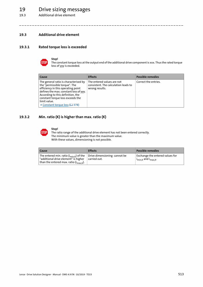
19 Drive sizing messages19.3 Additional drive element
_ _ _ _ _ _ _ _ _ _ _ _ _ _ _ _ _ _ _ _ _ _ _ _ _ _ _ _ _ _ _ _ _ _ _ _ _ _ _ _ _ _ _ _ _ _ _ _ _ _ _ _ _ _ _ _ _ _ _ _ _ _ _ _
19.3 Additional drive element
19.3.1 Rated torque loss is exceeded
19.3.2 Min. ratio (K) is higher than max. ratio (K)
Stop!The constant torque loss at the output end of the additional drive component is xxx. Thus the rated torque loss of yyy is exceeded.
Cause Effects Possible remedies
The general ratio is characterised by the "permissible torque". The efficiency in this operating point defines the max. constant loss of yyy. According to this definition, the constant torque loss exceeds the limit value.Constant torque loss ( 378)
The entered values are not consistent. The calculation leads to wrong results.
Correct the entries.
Stop!The ratio range of the additional drive element has not been entered correctly.The minimum value is greater than the maximum value.With these values, dimensioning is not possible.
Cause Effects Possible remedies
The entered min. ratio (imin,K) of the "additional drive element" is higher than the entered max. ratio (imax,K).
Drive dimensioning cannot be carried out.
Exchange the entered values for imin,K and imax,K.
Lenze · Drive Solution Designer · Manual · DMS 4.9 EN · 10/2019 · TD23 513

19 Drive sizing messages19.4 Lenze gearbox
_ _ _ _ _ _ _ _ _ _ _ _ _ _ _ _ _ _ _ _ _ _ _ _ _ _ _ _ _ _ _ _ _ _ _ _ _ _ _ _ _ _ _ _ _ _ _ _ _ _ _ _ _ _ _ _ _ _ _ _ _ _ _ _
19.4 Lenze gearbox
19.4.1 Utilisation >100 % regarding the equivalent torque
19.4.2 Utilisation > yyy %, regarding the max. torque
Note!
Warnings concerning the gearbox selection can already be caused by an unfavourable selection of the motor. If required, it is then reasonable to select a different motor.
Note!The utilisation of the gearbox with regard to the equivalent torque is xxx %. Thus the limit value of 100 % is exceeded. The gearbox is subject to heavy use.
Cause Effects Possible remedies
The gearbox is operated in the range of fatique strength and is not rated for endurance strength anymore.
• This load may only occur sporadically.
The expected service life possibly is not attained anymore at cyclic operation.
• Select gearbox with higher M2GN .• Select greater frame sizes (motor,
gearbox).
Check of the torque load ( 370)
Warning!The utilisation of the gearbox relative to the max. torque is xxx %. Thus the limit value of yyy % is exceeded.
Cause Effects Possible remedies
The gearbox is overloaded mechanically. It is operated beyond the static strength.
• This load is not permissible!
Limit values• 200 % (2 × Mper,out) in case of
helical gearbox, shaft-mounted helical gearbox, bevel gearbox, helical-bevel gearbox, helical-worm gearbox.
• 160 % (1.6 × Mper,out) in case of planetary gearbox.
The gearbox is destroyed after a short time!
Select bigger gearboxes.
Check of the torque load ( 370)
514 Lenze · Drive Solution Designer · Manual · DMS 4.9 EN · 10/2019 · TD23

19 Drive sizing messages19.4 Lenze gearbox
_ _ _ _ _ _ _ _ _ _ _ _ _ _ _ _ _ _ _ _ _ _ _ _ _ _ _ _ _ _ _ _ _ _ _ _ _ _ _ _ _ _ _ _ _ _ _ _ _ _ _ _ _ _ _ _ _ _ _ _ _ _ _ _
19.4.3 Utilisation >100 % regarding the max. speed
19.4.4 Utilisation >100 % regarding the thermal speed
19.4.5 Utilisation of the clutch >100 % regarding the torque
Warning!The utilisation of the gearbox relative to the max. speed is xxx %. Thus the limit value of 100 % is exceeded.
Cause Effects Possible remedies
The gearbox is thermally and mechanically overloaded, i. e. it is overheated and damaged by too higher speeds.
• This load is not permissible!
The gearbox is destroyed after a short time!
• Reduce the entry of intended gearbox input speed.
• Select motor with lower rated speed.
• Select lower ratio.• Select different mounting
position.
Check of the speed load ( 374)
Warning!The utilisation of the gearbox relative to the thermal speed is xxx %. Thus the limit value of 100 % is exceeded.
Cause Effects Possible remedies
The medium input speed of the gearbox is too high.
• The gearbox is thermally overloaded.
• By the losses generated within the gearbox, the gearbox will be destroyed within a short time!
Select a different gearbox!
Thermal utilisation ( 374)
Warning!The utilisation of the clutch relative to the torque is xxx %. Thus the limit value of 100 % is exceeded.
Cause Effects Possible remedies
The torque transmitted via the clutch is too high.
• The clutch between motor and gearbox in standard mounting is mechanically overloaded.
• The clutch is destroyed after a short time!
Select different gearbox or motor in direct mounting.
Check of the torque load ( 370)
Lenze · Drive Solution Designer · Manual · DMS 4.9 EN · 10/2019 · TD23 515

19 Drive sizing messages19.4 Lenze gearbox
_ _ _ _ _ _ _ _ _ _ _ _ _ _ _ _ _ _ _ _ _ _ _ _ _ _ _ _ _ _ _ _ _ _ _ _ _ _ _ _ _ _ _ _ _ _ _ _ _ _ _ _ _ _ _ _ _ _ _ _ _ _ _ _
19.4.6 Utilisation of the clutch >100 % regarding the speed
19.4.7 Thermal overload when mineral gearbox oil is used
19.4.8 Utilisation is xxx %, regarding the max. torque
Warning!The utilisation of the clutch (motor-gearbox) relative to the speed is xxx %. Thus the limit value of 100 % is exceeded.
Cause Effects Possible remedies
The medium motor speed is too high. • The clutch between motor and gearbox is overused.
• The clutch is destroyed after a short time!
• Select a different gearbox.• Optimise application.
Check of the torque load ( 370)
Note!When mineral oil is used, the gearbox will be thermally overloaded.Use Viton shaft sealing rings and use synthetic oil!
Cause Effects Possible remedies
Mineral oil is less temperature-stable, less powerful and has a smaller viscosity range than synthetic oil.
Use of mineral gearbox oil:• The gearbox is too hot.• The oil pressure increases.• The shaft sealing rings wear out.• The service life of the gearbox oil
is considerably reduced.
• Use synthetic gearbox oil.• When synthetic gearbox oil is
used, Viton shaft sealing rings have to be used.
Thermal utilisation ( 374)
Note!The utilisation of the gearbox is xxx %, regarding the max. torque. Thus the limit value of 100 % is exceeded.The gearbox is overloaded for a short time. The increased wear is within the permissible range.The utilisation is xxx %, regarding the fatique strength.
Cause Effects Possible remedies
The gearbox is not rated for endurance strength and will be overloaded after the simplified fatigue strength calculation.
• The service life of the gearbox is reduced.
• The increased wear is within the permissible range.
Select a different gearbox.
516 Lenze · Drive Solution Designer · Manual · DMS 4.9 EN · 10/2019 · TD23

19 Drive sizing messages19.4 Lenze gearbox
_ _ _ _ _ _ _ _ _ _ _ _ _ _ _ _ _ _ _ _ _ _ _ _ _ _ _ _ _ _ _ _ _ _ _ _ _ _ _ _ _ _ _ _ _ _ _ _ _ _ _ _ _ _ _ _ _ _ _ _ _ _ _ _
19.4.9 Load of the shaft sealing ring is xxx %, regarding the speed
19.4.10 Wear of the gearbox >100 %
19.4.11 Using synthetic oil for gearboxes of the winding application
Note!The load of the shaft sealing ring is xxx %, regarding the speed.This may cause reduced service intervals.
Cause Effects Possible remedies
The input speed for the shaft sealing ring on the motor side is too high.
The service life of the shaft sealing ring on the motor side is considerably reduced.
• Select a different gearbox.• Select motor with lower input
speed.
Thermal utilisation ( 374)
Warning!DSD has calculated a wear of xxx % for the gearbox.Thus the limit value of 100 % is exceeded.Contact your Lenze sales partner.
Cause Effects Possible remedies
DSD has detected in accordance with the defined operating conditions that the gearbox will not safely withstand five years of operation.
The expected service life will be possible not attained at cyclic operation.
• Can only be scrutinised by Lenze.• Contact Lenze sales partner and
arrange for the check to be made.
Note!Use synthetic oil (fuel-efficient engine oil) for the gearbox of this winding application.That way, friction is reduced.
Cause Effects Possible remedies
The viscosity and temperature stability of mineral oils are not suitable for repeatable, high torque setting ranges.
Repeatable minimum tensile forces cannot be reached.
Use synthetic oil.
Lenze · Drive Solution Designer · Manual · DMS 4.9 EN · 10/2019 · TD23 517

19 Drive sizing messages19.4 Lenze gearbox
_ _ _ _ _ _ _ _ _ _ _ _ _ _ _ _ _ _ _ _ _ _ _ _ _ _ _ _ _ _ _ _ _ _ _ _ _ _ _ _ _ _ _ _ _ _ _ _ _ _ _ _ _ _ _ _ _ _ _ _ _ _ _ _
19.4.12 No product options available
19.4.13 Too low load capacity of the geared motor for applications with a safety encoder
Note!No product options are available for the selected geared motor.Configure product options manually.
Cause Effects Possible remedies
In DSD, no product options are stored for the geared motor.
Product options cannot be selected. Configure product options manually:• »EASY Product Finder«• Product catalogue• SAP• Contact Lenze Sales department
Warning!A geared motor in combination with a safety encoder has been selected.The load capacity c of the geared motor is too low.In order to meet the requirements of the safety features, a geared motor with c > 1 must be used.
Cause Effects Possible remedies
When selecting a safety encoder it is automatically assumed that the application is to be combined with a safety system. In this case, the gearbox must only be loaded with a factor c 1.
When loading the gearbox with c < 1, the safe operation requested is no longer ensured.
Select a gearbox with a greater load capacity, so that c 1 is complied with.
518 Lenze · Drive Solution Designer · Manual · DMS 4.9 EN · 10/2019 · TD23

19 Drive sizing messages19.5 Lenze motor
_ _ _ _ _ _ _ _ _ _ _ _ _ _ _ _ _ _ _ _ _ _ _ _ _ _ _ _ _ _ _ _ _ _ _ _ _ _ _ _ _ _ _ _ _ _ _ _ _ _ _ _ _ _ _ _ _ _ _ _ _ _ _ _
19.5 Lenze motor
19.5.1 Utilisation >100 %, regarding the effective torque
19.5.2 Max. motor speed is higher than the permissible motor speed
19.5.3 Max. output torque is higher than the permissible motor torque
Warning!The utilisation of the motor relative to the effective torque is xxx %. Thus the limit value of 100 % is exceeded.
Cause Effects Possible remedies
The calculated effective torque of the application on the motor is higher than the permissible torque.
The motor is thermally overloaded. • Select different motor.• Select a higher ratio if the speed
range of the motor is badly utilised.
Warning!The max. occurring motor speed is xxx rpm. Thus the max. permissible motor speed of yyy rpm is exceeded.
Cause Effects Possible remedies
The maximum speed that occurs is higher than the maximum permissible speed of the motor.
The motor is mechanically destroyed! • Reduce gearbox ratio or speed.• Select motor with a higher
permissible speed.
Warning!The max. permissible output torque of the motor is exceeded.
Cause Effects Possible remedies
The maximum permissible output torque of the motor must not be exceeded. This limit is compared to the occurring max. torque (absolute value).
The motor is mechanically/electrically overloaded.
• Select bigger motor.• If required, reduce load.
• If the use of a gearbox is intended, the torque can be reduced by a greater ratio.
Lenze · Drive Solution Designer · Manual · DMS 4.9 EN · 10/2019 · TD23 519

19 Drive sizing messages19.5 Lenze motor
_ _ _ _ _ _ _ _ _ _ _ _ _ _ _ _ _ _ _ _ _ _ _ _ _ _ _ _ _ _ _ _ _ _ _ _ _ _ _ _ _ _ _ _ _ _ _ _ _ _ _ _ _ _ _ _ _ _ _ _ _ _ _ _
19.5.4 Motor is operated in the field weakening range
19.5.5 Max. mismatch is higher than permissible mismatch
19.5.6 Unstable control mode of the winding drive in the case of speed-controlled operation
Note!The field weakening factor of the motor is xxx.Hence, the limit value of yyy is exceeded. The motor is operated in the field weakening range.During field weakening operation, larger reserves must be provided for the inverter.
Cause Effects Possible remedies
In the field weakening range, the accuracy of the DSD current model is restricted.DSD cannot calculate correctly the thermal utilisation of the inverter.
The inverter is thermally overloaded. Select inverter with higher thermal reserves.
Field weakening ( 488)
Note!The max. mismatch of the motor is xxx.Hence, the max. permissible mismatch of the motor of yyy is exceeded.(only applicable to speed-controlled systems)
Cause Effects Possible remedies
The maximum mismatch exceeds the limit value defined.
The drive is inclined to vibrations and possibly is not controllable with regard to feedback control (only for speed control or position-controlled systems).For torque-controlled or VFC plus-controlled systems this value has a lower priority.
• Select gearbox with higher transmission ratio.
• Select motor with higher inertia (standard motor instead of servo motor).
Load-matching factor ( 351)
Note!The load-matching factor kj of xxx which has been determined is non-critical for this torque-controlled winding drive.However, if you switch over to a speed-controlled operating mode in specific operating phases (e.g. setting-up operation, emergency stop), other limit values apply to the kj factor.
Cause Effects Possible remedies
Unlike with the torque-controlled winding drive, the kj factor has a major impact when the speed-controlled winding drive is concerned.
Unstable response in speed-controlled operation.
Do not exceed the limit value for the mismatch kj for a speed-controlled winding drive.
Load-matching factor ( 351)
520 Lenze · Drive Solution Designer · Manual · DMS 4.9 EN · 10/2019 · TD23

19 Drive sizing messages19.5 Lenze motor
_ _ _ _ _ _ _ _ _ _ _ _ _ _ _ _ _ _ _ _ _ _ _ _ _ _ _ _ _ _ _ _ _ _ _ _ _ _ _ _ _ _ _ _ _ _ _ _ _ _ _ _ _ _ _ _ _ _ _ _ _ _ _ _
19.5.7 Required motor speed too low
19.5.8 Max. permissible motor current of yyy is exceeded
19.5.9 Overload of the motor >xxx %
Tip!The required max. motor speed is too low. It is xxx min-1.The recommended limit value of an optimum drive dimensioning is yyy min-1.
Cause Effects Possible remedies
With regard to their size, inverters are defined by the motor current. If the motor is only operated in the lower speed range with regard to its rated speed, the voltage provided by the inverter is not utilised.A different motor that would be operated more near its rated speed would improve the utilisation of the inverter.
Drive system possibly may not be at optimal cost.
Use a gearbox with a higher ratio, so that the motor at the same power is better utilised with regard to speed, and the inverter is better utilised with regard to voltage.
Note!The max. output current of the inverter is xxx A. Thus the max. permissible motor current of yyy A is exceeded.
Cause Effects Possible remedies
The max. output current of the inverter is higher than the max. permissible motor current.
• Compared to the motor, the inverter is overdimensioned.
• The motor winding can be destroyed by the too high output current.
• Synchronous motors can be demagnetized.
Limit the output current of the inverter to the value permissible for the motor.
Note!The overload of the motor is higher than xxx %. The thermal utilisation of the motor and the currents calculated for inverters and other components are not correct anymore. Up to an overload of yyy % the DSD can execute calculations with a sufficient accuracy.
Cause Effects Possible remedies
In case of high overloads, the torque-generating current share increases more than the torque due to saturations in the motor.
The currents calculated for the inverter and other components are not correct anymore.
Consider corresponding reserves when selecting the inverter.
Lenze · Drive Solution Designer · Manual · DMS 4.9 EN · 10/2019 · TD23 521

19 Drive sizing messages19.5 Lenze motor
_ _ _ _ _ _ _ _ _ _ _ _ _ _ _ _ _ _ _ _ _ _ _ _ _ _ _ _ _ _ _ _ _ _ _ _ _ _ _ _ _ _ _ _ _ _ _ _ _ _ _ _ _ _ _ _ _ _ _ _ _ _ _ _
19.5.10 Max. permissible ambient temperature of the blower is exceeded
19.5.11 A continuous operation characteristic for inverter operation is not available
19.5.12 Motor temperature too high at switching frequency < 8 kHz
Warning!The ambient temperature of the motor or geared motor is XXX °C. Thus, the max. permissible ambient temperature of the blower of 40 °C is exceeded.
Cause Effects Possible remedies
The permissible ambient temperature of the blower is exceeded.
The blower is overheated and may fail. This may cause the motor to overheat and fail as well.
Select motor without blower.
Note!There is no continuous operation characteristic for the motor if operated on an inverter.The equivalent characteristic does not take account of restrictions on motor operation due to its ventilation.
Cause Effects Possible remedies
There is no data for this self-ventilated motor.
The motor may get too hot when being operated at field frequencies < 20 Hz.
• In case of long operations at low speed or with high thermal utilisation, select a motor with forced ventilation.
• Select a more powerful motor.
Note!The motor selected must not be permanently operated at a switching frequency < 8 kHz.Set a fixed switching frequency on the inverter to ensure that it is not automatically reduced.
Cause Effects Possible remedies
At low switching frequencies the losses in the motor increase.
Motor gets too hot. • Select bigger motor.• Set switching frequency
permanently to min. 8 kHz if the drive continuously runs with a too low switching frequency.
Effects of low switching frequencies on the motor ( 495)
522 Lenze · Drive Solution Designer · Manual · DMS 4.9 EN · 10/2019 · TD23

19 Drive sizing messages19.5 Lenze motor
_ _ _ _ _ _ _ _ _ _ _ _ _ _ _ _ _ _ _ _ _ _ _ _ _ _ _ _ _ _ _ _ _ _ _ _ _ _ _ _ _ _ _ _ _ _ _ _ _ _ _ _ _ _ _ _ _ _ _ _ _ _ _ _
19.5.13 Limit value of xxx % of the rated torque is exceeded
19.5.14 Compliance with ErP Directive 2009/125/EC
Warning!The utilisation of the motor is xxx % of the rated torque.If the motor is operated on an inverter with V/f control, the limit value of yyy % is exceeded.The operation is not permissible!
Cause Effects Possible remedies
With a V/f characteristic control without feedback and low speed range, the motor is not magnetised as required. The motor cannot reach the rated torque anymore.
The hoist drive cannot hold the load. • With a rated motor power < 7.5 kW, select a bigger motor.
• Select a control mode with feedback.
Note!According to the ErP Directive, the selected motor may only be put into circulation together with a brake.
Cause Effects Possible remedies
In accordance with the specifications laid down by ErP Directive 2009/125/EC, new requirements have applied as from 01.01.2015 for placing motors on the market.
• When the motor is actuated without a brake and without a frequency inverter, the power range from 7.5 kW to 375 kW at least requires the use of a motor with efficiency class IE3.
• When the motor is actuated without a brake and with a frequency inverter, the power range from 7.5 kW to 375 kW at least requires the use of a motor with efficiency class IE2.
The motor selected must not be introduced to the market within the EU.
• Select a motor meeting the efficiency class required, e.g.:• High efficiency motor
(MHxMA)• Premium efficiency motor
(m500-P)• Motor optimised for frequency
inverter (MFxMA)• Lenze Smart motor• Servo motor
• Special regulations for Switzerland and countries outside the EU.
Notes on energy directives can be found on http://www.Lenze.com
Lenze · Drive Solution Designer · Manual · DMS 4.9 EN · 10/2019 · TD23 523

19 Drive sizing messages19.5 Lenze motor
_ _ _ _ _ _ _ _ _ _ _ _ _ _ _ _ _ _ _ _ _ _ _ _ _ _ _ _ _ _ _ _ _ _ _ _ _ _ _ _ _ _ _ _ _ _ _ _ _ _ _ _ _ _ _ _ _ _ _ _ _ _ _ _
19.5.15 No check of the thermal motor utilisation in accordance with UL requirements
19.5.16 Overdimensioned motor in the case of traction-controlled winding drive
19.5.17 Speed-controlled winding drive may show unstable behaviour
Note!The DSD does not check the UL-compliant thermal motor utilisation in the lower speed range.
Cause Effects Possible remedies
In order to meet UL requirements, the motor requires sufficient thermal overload protection.The DSD does not check whether the requirements in compliance with UL are met.In order to meet these requirements, the I²xt motor monitoring function in the inverter must be activated, which is not checked in the DSD.
The thermal overload protection of the motor may not be UL-compliant.
• Parameterise motor protection by a motor monitoring function integrated in the inverter (e.g. I×t monitoring)
• Ensure motor protection by external components.
• Derating of the thermal continuous operation characteristic of the motor of 0 ... 40 Hz.• The characteristic may deviate
from the characteristic shown in the DSD.
• More information can be found in the inverter hardware manual.
Tip!The utilisation of the motor is xxx, relative to the stationary torque.The motor is clearly overdimensioned for traction-controlled winding drives with a torque setting range of yyy. Select another motor.
Cause Effects Possible remedies
In this torque setting range, a clearly overdimensioned motor is only able to work to a limited extent.
Lower tensile forces cannot be reached or cannot be repeated.
Dimension the motor in a demand-oriented way.
Note!With a load-matching factor of xxx, the control system of speed-controlled drives in combination with load alternations and weakly damped mechanical transmission elements with backlash between motor and winding shaft may show unstable behaviour.Have the application checked by the technical support.
Cause Effects Possible remedies
The load-matching factor kj results from the mass and the diameter of the full reel, the gearbox ratio and the moment of inertia of the motor.
Unstable control mode. • Reduce the load-matching factor kj through a higher moment of inertia of the motor of a higher gearbox ratio.
• Optimise the motor control.
524 Lenze · Drive Solution Designer · Manual · DMS 4.9 EN · 10/2019 · TD23

19 Drive sizing messages19.5 Lenze motor
_ _ _ _ _ _ _ _ _ _ _ _ _ _ _ _ _ _ _ _ _ _ _ _ _ _ _ _ _ _ _ _ _ _ _ _ _ _ _ _ _ _ _ _ _ _ _ _ _ _ _ _ _ _ _ _ _ _ _ _ _ _ _ _
19.5.18 Field weakening factor kf > as winding ratio q
19.5.19 Activate "brake at standstill"
19.5.20 Activate "controller inhibit at standstill"
Warning!The field weakening factor kf is xxx.The winding ratio q is yyy.For an optimally adapted drive, k f must be < q.
Cause Effects Possible remedies
The field weakening factor kf entered is greater than the winding ratio q.
The drive solution is not optimal with regard to the utilisation of the torque-speed requirement.
Check the torque-speed requirement in the M-n characteristic of the motor, or set kf < q.
Stop!You have selected a mechanical brake.For the Lenze Smart Motor, the brake at standstill is automatically activated.In order that the DSD can consider this function correctly, you have to activate the "brake at standstill" in the "motion" dimensioning step.
Cause Effects Possible remedies
In case of the Lenze Smart Motor, a brake at standstill is automatically applied.
The brake control cannot be selected. Correct the selection in the Motion dimensioning step.
Stop!At standstill, the Lenze Smart Motor is automatically deenergised.In order that the DSD can consider this function correctly, you have to activate the "controller inhibit at standstill" in the "motion" dimensioning step.
Cause Effects Possible remedies
For the Lenze Smart Motor, the controller inhibit at standstill is automatically activated.
The activation of the controller inhibit cannot be configured.
Correct the selection in the Motion dimensioning step.
Lenze · Drive Solution Designer · Manual · DMS 4.9 EN · 10/2019 · TD23 525

19 Drive sizing messages19.5 Lenze motor
_ _ _ _ _ _ _ _ _ _ _ _ _ _ _ _ _ _ _ _ _ _ _ _ _ _ _ _ _ _ _ _ _ _ _ _ _ _ _ _ _ _ _ _ _ _ _ _ _ _ _ _ _ _ _ _ _ _ _ _ _ _ _ _
19.5.21 Motor speed falls below the limit speed of 500 rpm
19.5.22 Motor speed exceeds limit speed of 2600 rpm
19.5.23 Thermal utilisation of the synchronous servo motor is exceeded
Stop!The steady-state motor speed of xxx falls below the limit speed of 500 rpm.Select another gearbox ratio.
Cause Effects Possible remedies
Unfavourable adaptation of the motor speed to the speed of the application.
The desired speed is not reached with the selected gearbox ratio.
• Select another gearbox ratio.• Adapt motor speed:
• Select additional ratio.• Increase velocity or speed of the
application.
Stop!The steady-state motor speed of xxx exceeds the limit speed of 2600 rpm.Select another gearbox ratio.
Cause Effects Possible remedies
Unfavourable adaptation of the motor speed to the speed of the application.
The desired speed is not reached with the selected gearbox ratio.
• Select another gearbox ratio.• Adapt motor speed:
• Select additional ratio.• Reduce velocity or speed of the
application.
Warning!Under unfavourable conditions, the motor at standstill is thermally overloaded.
Cause Effects Possible remedies
Depending on the position of the rotor at standstill, the current of a phase can overload the motor winding.
The motor is thermally damaged. Dimension the drive with electromechanical brake and activated the brake at standstill.
526 Lenze · Drive Solution Designer · Manual · DMS 4.9 EN · 10/2019 · TD23

19 Drive sizing messages19.5 Lenze motor
_ _ _ _ _ _ _ _ _ _ _ _ _ _ _ _ _ _ _ _ _ _ _ _ _ _ _ _ _ _ _ _ _ _ _ _ _ _ _ _ _ _ _ _ _ _ _ _ _ _ _ _ _ _ _ _ _ _ _ _ _ _ _ _
19.5.24 Deceleration time exceeds permissible time of 20 s
19.5.25 Acceleration time exceeds permissible time of 20 s
19.5.26 Max. motor torque is exceeded
Stop!The deceleration time of xxx s to be parameterised in the Lenze Smart Motor exceeds the permissible time of 20 s.Change the deceleration time or the gearbox ratio.
Cause Effects Possible remedies
The deceleration time of the Lenze Smart Motor corresponds to the deceleration time of the ramp generator from nmax to n = 0.DSD calculates the deceleration time from the defined motion.
The deceleration time calculated by the DSD cannot be entered into the Lenze Smart Motor.
• Select another gearbox ratio.• Reduce deceleration time.
Warning!The acceleration time of xxx s to be parameterised in the Lenze Smart Motor exceeds the permissible time of 20 s.Change the acceleration time or gearbox ratio.
Cause Effects Possible remedies
The acceleration time of the Lenze Smart Motor corresponds to the acceleration time of the ramp generator from n = 0 to nmax.DSD calculates the acceleration time from the defined motion.
The acceleration time calculated by the DSD cannot be entered into the Lenze Smart Motor.
• Select another gearbox ratio.• Reduce acceleration time.
Warning!The available maximum torque of the Lenze Smart Motor is exceeded.
Cause Effects Possible remedies
The maximum torque is limited by the gearbox or the motor.
The drive system cannot execute the defined motion.
• Adapt data to the application.• Select a different gearbox.
Lenze · Drive Solution Designer · Manual · DMS 4.9 EN · 10/2019 · TD23 527

19 Drive sizing messages19.5 Lenze motor
_ _ _ _ _ _ _ _ _ _ _ _ _ _ _ _ _ _ _ _ _ _ _ _ _ _ _ _ _ _ _ _ _ _ _ _ _ _ _ _ _ _ _ _ _ _ _ _ _ _ _ _ _ _ _ _ _ _ _ _ _ _ _ _
19.5.27 Longer braking distance during operation in generator mode below 500 rpm
19.5.28 Permissible ambient temperature exceeds 40 °C
19.5.29 Incomplete check of emergency stop
Note!When decelerating during operation in generator mode below 500 rpm, the braking distance may slightly increase (longer deceleration ramp).
Cause Effects Possible remedies
The torque in generator mode at low speeds is reduced.
The deceleration ramp specified is not complied with; the braking distance increases.
• The deviation is usually substantially below the braking distance tolerance of an electromechanical brake.
If the impact to the application is relevant:
• Select bigger motor.• Select a different drive concept.
Warning!The Lenze Smart Motor cannot be actuated. The maximum permissible ambient temperature of 40 °C is exceeded.
Cause Effects Possible remedies
The maximum ambient temperature for the Lenze Smart Motor is 40 °C.
The Lenze Smart Motor is overheated and switches off.
Select a different drive concept.
Note!The check of emergency stop is incomplete.The thermal utilisation of the drive components is not checked.Braking circuits are not dimensioned.
Cause Effects Possible remedies
The DSD calculates the motor torque required for emergency stop from the emergency stop time entered, assuming a linear motion profile and a tensile force of 0 N (material crack). The torque calculated is represented in the M-n characteristic of the motor.
• Further important conditions for checking the emergency stop scenario cannot be taken into consideration by the DSD.
An emergency stop may proceed more unfavourable than has been calculated by the DSD.
Carry out dimensioning for the most unfavourable emergency stop case manually.
528 Lenze · Drive Solution Designer · Manual · DMS 4.9 EN · 10/2019 · TD23
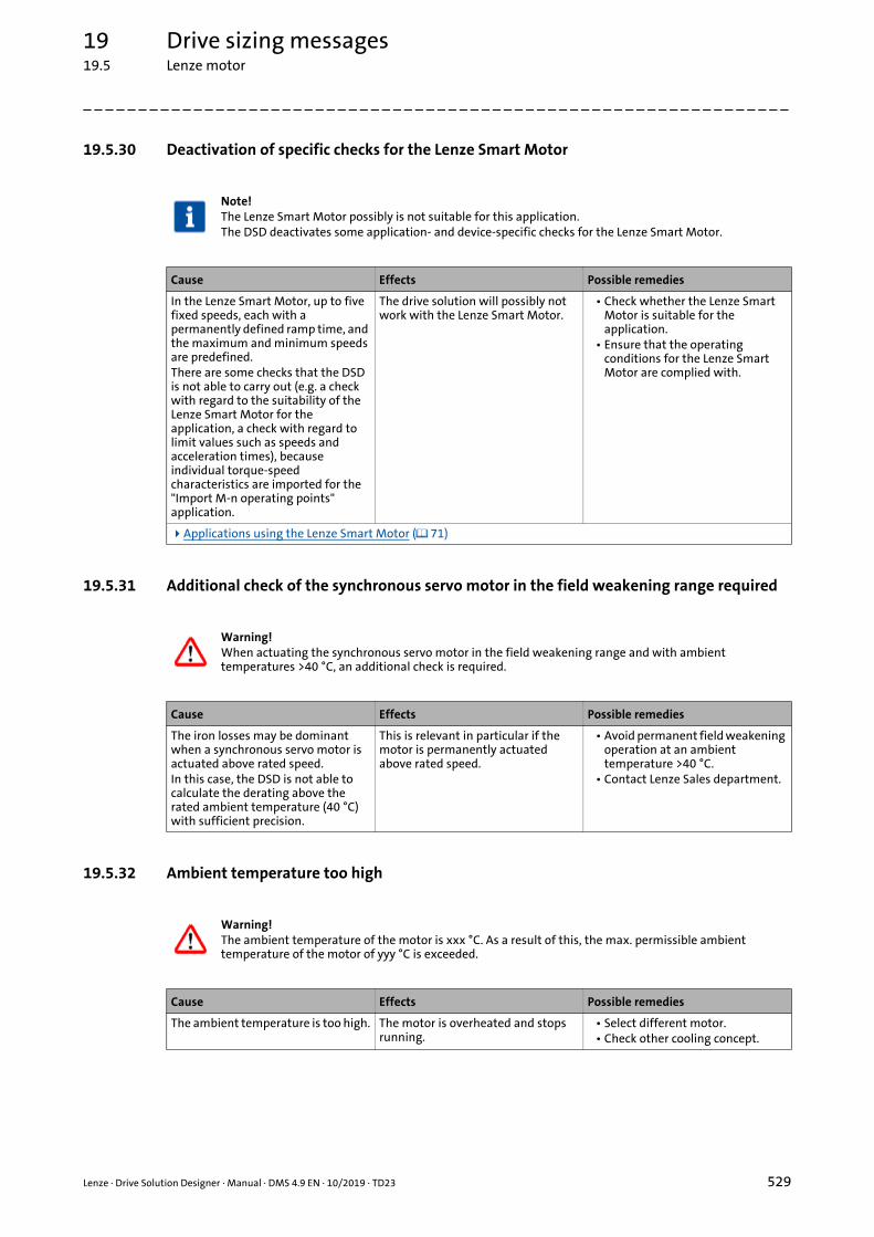
19 Drive sizing messages19.5 Lenze motor
_ _ _ _ _ _ _ _ _ _ _ _ _ _ _ _ _ _ _ _ _ _ _ _ _ _ _ _ _ _ _ _ _ _ _ _ _ _ _ _ _ _ _ _ _ _ _ _ _ _ _ _ _ _ _ _ _ _ _ _ _ _ _ _
19.5.30 Deactivation of specific checks for the Lenze Smart Motor
19.5.31 Additional check of the synchronous servo motor in the field weakening range required
19.5.32 Ambient temperature too high
Note!The Lenze Smart Motor possibly is not suitable for this application.The DSD deactivates some application- and device-specific checks for the Lenze Smart Motor.
Cause Effects Possible remedies
In the Lenze Smart Motor, up to five fixed speeds, each with a permanently defined ramp time, and the maximum and minimum speeds are predefined.There are some checks that the DSD is not able to carry out (e.g. a check with regard to the suitability of the Lenze Smart Motor for the application, a check with regard to limit values such as speeds and acceleration times), because individual torque-speed characteristics are imported for the "Import M-n operating points" application.
The drive solution will possibly not work with the Lenze Smart Motor.
• Check whether the Lenze Smart Motor is suitable for the application.
• Ensure that the operating conditions for the Lenze Smart Motor are complied with.
Applications using the Lenze Smart Motor ( 71)
Warning!When actuating the synchronous servo motor in the field weakening range and with ambient temperatures >40 °C, an additional check is required.
Cause Effects Possible remedies
The iron losses may be dominant when a synchronous servo motor is actuated above rated speed. In this case, the DSD is not able to calculate the derating above the rated ambient temperature (40 °C) with sufficient precision.
This is relevant in particular if the motor is permanently actuated above rated speed.
• Avoid permanent field weakening operation at an ambient temperature >40 °C.
• Contact Lenze Sales department.
Warning!The ambient temperature of the motor is xxx °C. As a result of this, the max. permissible ambient temperature of the motor of yyy °C is exceeded.
Cause Effects Possible remedies
The ambient temperature is too high. The motor is overheated and stops running.
• Select different motor.• Check other cooling concept.
Lenze · Drive Solution Designer · Manual · DMS 4.9 EN · 10/2019 · TD23 529
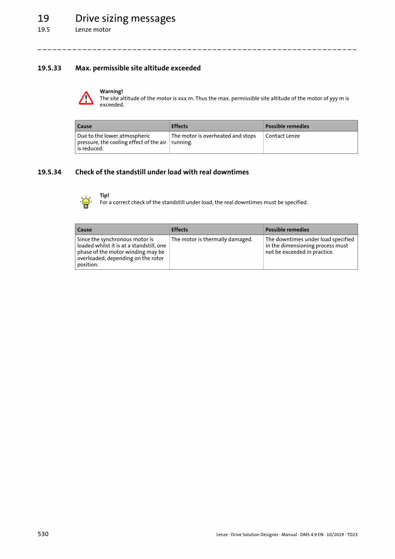
19 Drive sizing messages19.5 Lenze motor
_ _ _ _ _ _ _ _ _ _ _ _ _ _ _ _ _ _ _ _ _ _ _ _ _ _ _ _ _ _ _ _ _ _ _ _ _ _ _ _ _ _ _ _ _ _ _ _ _ _ _ _ _ _ _ _ _ _ _ _ _ _ _ _
19.5.33 Max. permissible site altitude exceeded
19.5.34 Check of the standstill under load with real downtimes
Warning!The site altitude of the motor is xxx m. Thus the max. permissible site altitude of the motor of yyy m is exceeded.
Cause Effects Possible remedies
Due to the lower atmospheric pressure, the cooling effect of the air is reduced.
The motor is overheated and stops running.
Contact Lenze
Tip!For a correct check of the standstill under load, the real downtimes must be specified.
Cause Effects Possible remedies
Since the synchronous motor is loaded whilst it is at a standstill, one phase of the motor winding may be overloaded, depending on the rotor position.
The motor is thermally damaged. The downtimes under load specified in the dimensioning process must not be exceeded in practice.
530 Lenze · Drive Solution Designer · Manual · DMS 4.9 EN · 10/2019 · TD23

19 Drive sizing messages19.6 Brake
_ _ _ _ _ _ _ _ _ _ _ _ _ _ _ _ _ _ _ _ _ _ _ _ _ _ _ _ _ _ _ _ _ _ _ _ _ _ _ _ _ _ _ _ _ _ _ _ _ _ _ _ _ _ _ _ _ _ _ _ _ _ _ _
19.6 Brake
19.6.1 Rated torque/dimensioning torque < safety factor of the brake
19.6.2 Holding brake: Function and emergency stop
19.6.3 No brake available
Warning!The characteristic torque/dimensioning torque of the brake is xxx. Thus the required braking torque which was determined with the required safety factor of yyy is not reached.
Cause Effects Possible remedies
The required safety factor is not achieved.
The brake slips, the load is not held. Use larger or uprated brake, or use a different motor with a larger brake.
Note!Function as holding brakeIn the DSD, the dimensioning of the electromechanical brake as holding brake is only carried out for standstill.The dimensioning as service brake, taking the speed-dependent decreasing braking torque and the max. permissible friction energy into consideration, has to be carried out manually.
Holding brake with emergency stop functionBefore commissioning, ensure that the brake installed at the motor is ground in correctly. Only a brake that is ground in and dimensioned correctly produces the braking torque required for the application. Due to their reduced braking effect, in particular for hoist applications or applications with a high kinetic energy (e.g. winders, motion drives), motor brakes that are not ground in present a source of danger.Depending on the application, the grinding process of the brake must be repeated cyclically.
Cause Effects Possible remedies
For the selected application, the electromechanical brake is required as service brake or holding brake.
The function required is not implemented correctly. In case of an emergency, the drive is not safely braked.
The dimensioning as service brake must be carried out manually.For a holding brake with emergency stop function, only use a brake that has been ground in.
Warning!No motor brake has been selected for the drive!For safety reasons, a suitable brake assembly is required (electromechanical motor brake or another braking system).
Cause Effects Possible remedies
The application requires a mechanical brake.
In case of an emergency, the drive cannot be braked safely.
Select a motor with brake.
Lenze · Drive Solution Designer · Manual · DMS 4.9 EN · 10/2019 · TD23 531

19 Drive sizing messages19.6 Brake
_ _ _ _ _ _ _ _ _ _ _ _ _ _ _ _ _ _ _ _ _ _ _ _ _ _ _ _ _ _ _ _ _ _ _ _ _ _ _ _ _ _ _ _ _ _ _ _ _ _ _ _ _ _ _ _ _ _ _ _ _ _ _ _
19.6.4 Permanent magnet holding brake is not suitable for hoist drives
19.6.5 Import of a motion profile - no check of the mechanical brake
19.6.6 Brake in the motion profile not activated - no check of the mechanical brake
Warning!For safety reasons, the permanent magnet holding brake selected is not suitable for hoist drives (reduced braking torque at higher speeds).Select a motor with a spring-applied brake or ensure that an additional brake assembly provides for the required safety.
Cause Effects Possible remedies
The braking torque decreases significantly at higher motor speeds.
Braking torque is too low in case of an emergency (mains failure, malfunction, inverter failure). Safe braking to standstill is not possible.
• Select a motor with a spring-applied brake.
• Provide for redundant brake assembly.
Mechanical brake selection ( 360)
Note!During the import of a torque/speed motion profile, a check of the mechanical brake as holding brake is not possible.Carry out this check manually.
Cause Effects Possible remedies
The drive dimensioning is based on imported data. With these data, DSD cannot check the brake in an application-specific way.
The required holding torque is too low. The drive is not braked safely.
Check the brake manually according to the requirements (brake type, braking torque, safety aspects). Mechanical brake selection ( 360)
Note!It is not possible to check the mechanical brake as holding brake.In the motion profile, application of the brake must be activated so that the DSD carries out the check.
Cause Effects Possible remedies
The DSD can only check the mechanical brake as holding brake if the application of the brake is set correctly in the motion profile.
It is not possible to check the mechanical brake as holding brake.
Correct the motion profile:• Set the "Brake activated" basic
value in the parameter profile for every application of the brake.
"Line" tab": Parameter profile ( 267)
532 Lenze · Drive Solution Designer · Manual · DMS 4.9 EN · 10/2019 · TD23

19 Drive sizing messages19.6 Brake
_ _ _ _ _ _ _ _ _ _ _ _ _ _ _ _ _ _ _ _ _ _ _ _ _ _ _ _ _ _ _ _ _ _ _ _ _ _ _ _ _ _ _ _ _ _ _ _ _ _ _ _ _ _ _ _ _ _ _ _ _ _ _ _
19.6.7 Holding brake is not suitable for the non-linear application
NoteWhere applicable, please check that the selected holding brake is suitable for safely holding the load in place in all possible settings of the non-linear application.
The selected holding brake may not be suitable to safely hold the load in place in all positions of this non-linear application.A manual check is required.
Cause Effects Possible remedies
The DSD checks the required torque at the brake in the specified standstill positions in the motion profile.If the actual position of the non-linear application deviates from the standstill position specified, a greater holding torque may be required. This situation may be brought about by an unscheduled stop of the slider-crank mechanism or eccentric lift table (e.g. in the event of a fault).
• The non-linear application can assume a position of equilibrium.
• In a standstill position in the upper dead centre, a small deviation from the position already results in a significant increase in the torque required.
• Check whether the impacts are relevant for the application.
• Use a suitable brake assembly.
Lenze · Drive Solution Designer · Manual · DMS 4.9 EN · 10/2019 · TD23 533
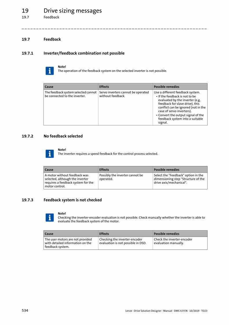
19 Drive sizing messages19.7 Feedback
_ _ _ _ _ _ _ _ _ _ _ _ _ _ _ _ _ _ _ _ _ _ _ _ _ _ _ _ _ _ _ _ _ _ _ _ _ _ _ _ _ _ _ _ _ _ _ _ _ _ _ _ _ _ _ _ _ _ _ _ _ _ _ _
19.7 Feedback
19.7.1 Inverter/feedback combination not possible
19.7.2 No feedback selected
19.7.3 Feedback system is not checked
Note!The operation of the feedback system on the selected inverter is not possible.
Cause Effects Possible remedies
The feedback system selected cannot be connected to the inverter.
Servo inverters cannot be operated without feedback.
Use a different feedback system.• If the feedback is not to be
evaluated by the inverter (e.g. feedback for slave drive), this conflict can be ignored (not in the case of servo inverters).
• Convert the output signal of the feedback system into a suitable signal.
Note!The inverter requires a speed feedback for the control process selected.
Cause Effects Possible remedies
A motor without feedback was selected, although the inverter requires a feedback system for the motor control.
Possibly the inverter cannot be operated.
Select the "Feedback" option in the dimensioning step "Structure of the drive axis/mechanical".
Note!Checking the inverter-encoder evaluation is not possible. Check manually whether the inverter is able to evaluate the feedback system of the motor.
Cause Effects Possible remedies
The user motors are not provided with detailed information on the feedback system.
Checking the inverter-encoder evaluation is not possible in DSD.
Check the inverter-encoder evaluation manually.
534 Lenze · Drive Solution Designer · Manual · DMS 4.9 EN · 10/2019 · TD23

19 Drive sizing messages19.7 Feedback
_ _ _ _ _ _ _ _ _ _ _ _ _ _ _ _ _ _ _ _ _ _ _ _ _ _ _ _ _ _ _ _ _ _ _ _ _ _ _ _ _ _ _ _ _ _ _ _ _ _ _ _ _ _ _ _ _ _ _ _ _ _ _ _
19.7.4 Feedback system for safety-oriented applications is not checked
19.7.5 Unstable control response of the speed-controlled winding drive
19.7.6 Evaluation of feedback not possible in One Cable Technology
19.7.7 The feedback is designed in One Cable Technology
Note!The feedback system selected is suitable for safety-oriented applications.DSD does not check whether the inverter supports this functionality.Make sure that an inverter with implemented safety functions (e. g. "Safely limited speed") is used. Servo Drives 9400 support the safety functions, e.g. by means of the SM301 safety module.
Cause Effects Possible remedies
DSD does not check whether the inverter supports safety functions.
The desired safety functions are not guaranteed.
For Servo Drives 9400 HighLine, select the SM301 safety module in the product options.
Note!The resolution of the feedback system selected is too low.In order to ensure an optimum control response, a feedback system with a resolution starting from 512 pulses per revolution is recommended.
Cause Effects Possible remedies
For a speed-controlled winding system, a feedback system with a very low resolution (e.g. 128, 256 increments) is used.
This very low resolution causes instabilities in the speed control.
• Select an encoder with a higher resolution (at least 512 pulses per revolution).
• Select a resolver or a SinCos encoder.
Warning!A feedback in One Cable Technology has been selected that is currently only supported by i950 servo inverters in the power range up to and including 15 kW.
Cause Effects Possible remedies
The selected feedback system cannot be connected to the inverter.
Servo inverters cannot be operated without feedback.
Use a different feedback system.
Tip!The selected feedback is designed in One Cable Technology.
Cause Effects Possible remedies
Digital absolute value encoders in One Cable Technology are available for series m850 and MCS servo motors in combination with i950 servo inverters.
The motor cable and encoder cable are combined in a hybrid cable.
–
Lenze · Drive Solution Designer · Manual · DMS 4.9 EN · 10/2019 · TD23 535

19 Drive sizing messages19.8 Inverter
_ _ _ _ _ _ _ _ _ _ _ _ _ _ _ _ _ _ _ _ _ _ _ _ _ _ _ _ _ _ _ _ _ _ _ _ _ _ _ _ _ _ _ _ _ _ _ _ _ _ _ _ _ _ _ _ _ _ _ _ _ _ _ _
19.8 Inverter
19.8.1 Ambient temperature too high
19.8.2 Max. permissible site altitude exceeded
19.8.3 Max. output current exceeded
Warning!The ambient temperature of the inverter is xxx °C. Thus the max. permissible ambient temperature of the inverter of yyy °C is exceeded.
Cause Effects Possible remedies
The ambient temperature is too high. The inverter switches itself off due to a too high heatsink temperature.
• Select a different inverter.• Select air-conditioned control
cabinet.• Check other cooling concept.
Warning!The site altitude of the inverter is xxx m. Thus the max. permissible site altitude of the inverter of yyy m is exceeded.
Cause Effects Possible remedies
Due to the lower atmospheric pressure, the cooling effect of the air is reduced.
The inverter is not cooled sufficiently and switches itself off due to a too high heatsink temperature.
Contact Lenze
Warning!The utilisation of the inverter relative to the max. current is xxx %. Thus the limit value of 100 % is exceeded.
Cause Effects Possible remedies
The maximum output current of the inverter is too low.
• Drive does not start.• Hoist sags.• Drive cannot follow the motion
profile.
• Select a greater inverter, or one with a higher overload capacity.
• Improve the utilisation of the inverter voltage range: • If the motor is not operated at
rated speed, it might be possible to improve the utilisation of the voltage range by adapting the gearbox ratio, and thus reduce the current required.
536 Lenze · Drive Solution Designer · Manual · DMS 4.9 EN · 10/2019 · TD23
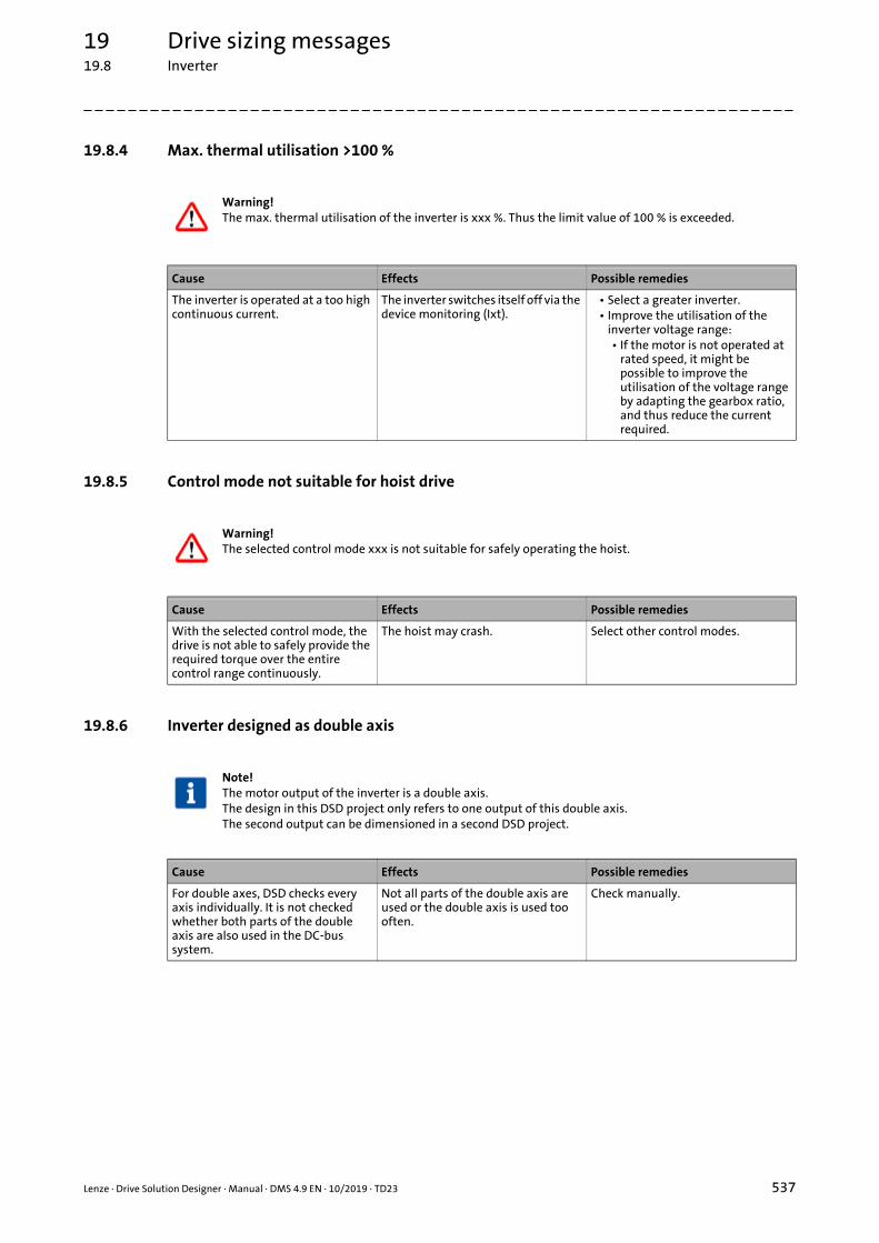
19 Drive sizing messages19.8 Inverter
_ _ _ _ _ _ _ _ _ _ _ _ _ _ _ _ _ _ _ _ _ _ _ _ _ _ _ _ _ _ _ _ _ _ _ _ _ _ _ _ _ _ _ _ _ _ _ _ _ _ _ _ _ _ _ _ _ _ _ _ _ _ _ _
19.8.4 Max. thermal utilisation >100 %
19.8.5 Control mode not suitable for hoist drive
19.8.6 Inverter designed as double axis
Warning!The max. thermal utilisation of the inverter is xxx %. Thus the limit value of 100 % is exceeded.
Cause Effects Possible remedies
The inverter is operated at a too high continuous current.
The inverter switches itself off via the device monitoring (Ixt).
• Select a greater inverter.• Improve the utilisation of the
inverter voltage range: • If the motor is not operated at
rated speed, it might be possible to improve the utilisation of the voltage range by adapting the gearbox ratio, and thus reduce the current required.
Warning!The selected control mode xxx is not suitable for safely operating the hoist.
Cause Effects Possible remedies
With the selected control mode, the drive is not able to safely provide the required torque over the entire control range continuously.
The hoist may crash. Select other control modes.
Note!The motor output of the inverter is a double axis.The design in this DSD project only refers to one output of this double axis.The second output can be dimensioned in a second DSD project.
Cause Effects Possible remedies
For double axes, DSD checks every axis individually. It is not checked whether both parts of the double axis are also used in the DC-bus system.
Not all parts of the double axis are used or the double axis is used too often.
Check manually.
Lenze · Drive Solution Designer · Manual · DMS 4.9 EN · 10/2019 · TD23 537

19 Drive sizing messages19.8 Inverter
_ _ _ _ _ _ _ _ _ _ _ _ _ _ _ _ _ _ _ _ _ _ _ _ _ _ _ _ _ _ _ _ _ _ _ _ _ _ _ _ _ _ _ _ _ _ _ _ _ _ _ _ _ _ _ _ _ _ _ _ _ _ _ _
19.8.7 Current resolution is not adapted to the motor
19.8.8 Utilisation of the inverter >100 %
19.8.9 Utilisation of the inverter too high after mains connection
Note!The current resolution of the inverter is not adapted to the motor. The rated motor current is vvv A. Thus the max. output current of the inverter of www A is much greater than the rated motor current.
The factor for the ratio of the rated motor current and the max. output current of the inverter is xxx.The factor is still reasonable.The factor zzz must not be exceeded.
Cause Effects Possible remedies
Due to the high rated current of the inverter compared to the rated motor current, the current detection in the inverter is unfavourable with regard to the motor currents.
Unfavourable control properties and a disadvantageous behaviour with regard to smooth running.
• Select a smaller inverter.• Select an inverter with an
overload behaviour that is better adapted.
Dimensioning criteria ( 383)
l
Warning!The max. utilisation of the inverter is xxx %, regarding the power pulse current.Thus the limit value of 100 % is exceeded.
Cause Effects Possible remedies
The inverter is overloaded by a too high and too long current pulse (e.g. due to an acceleration process).
The device is switched off with an error message due to device utilisation.
• Select a more powerful inverter.• Change motion or load profile to
reduce the height or duration of the current pulse.
Note!The I×t utilisation directly after mains connection and with max. ambient temperature is max. xxx %. The drive cannot start with the motion profile.
Cause Effects Possible remedies
After mains connection, the inverter is overloaded by a too high and too long current pulse (e.g. due to an acceleration process).For safety reasons, a preload of the inverter is assumed before mains connection.
The device is switched off with an error message due to overload.
• Switch on a load with a short delay.
• Select a more powerful inverter.• Change motion or load profile to
reduce the height or duration of the current pulse.
538 Lenze · Drive Solution Designer · Manual · DMS 4.9 EN · 10/2019 · TD23

19 Drive sizing messages19.8 Inverter
_ _ _ _ _ _ _ _ _ _ _ _ _ _ _ _ _ _ _ _ _ _ _ _ _ _ _ _ _ _ _ _ _ _ _ _ _ _ _ _ _ _ _ _ _ _ _ _ _ _ _ _ _ _ _ _ _ _ _ _ _ _ _ _
19.8.10 VFC plus control mode without feedback not permissible
19.8.11 The SLVC control mode is not permissible for inverters >55 kW
19.8.12 Too low braking torques at low speed
19.8.13 Motor limit rating is exceeded
Warning!In the case of the hoist drive, it is not permissible to combine a Servo Drive 9400 greater than 55 kW with a VFC plus control mode without feedback.
Cause Effects Possible remedies
The control mode is not suitable for hoist drives.
The drive must not be operated in this control mode.
Select a control mode with feedback.
Warning!The SLVC control mode is not permissible for inverters with a rating of more than 55 kW.
Cause Effects Possible remedies
The SLVC control mode must not be used for inverters in this power range.
The drive must not be operated in this control mode. The control is not stable!
Select a control mode with feedback.
Note!The drive system only develops small amounts of braking torque at low speeds in SLVC operating mode. Use alternative braking methods such as DC-injection braking or mechanical brakes.
Cause Effects Possible remedies
The drive system only develops small amounts of braking torque at low speeds in the SLVC control mode.
At low speeds with operation in generator mode, the motor cannot be controlled.
• Select a control mode with feedback.
• In this control mode, do not operate the drive permanently at low speeds .
• Do not use the control mode with hoist drives.
Warning!The rated motor power is xxx kW. In the "V/f control" mode, the max. motor limit rating of yyy kW is exceeded. The selected drive system cannot ensure a safe hoist operation.
Cause Effects Possible remedies
The rated motor power is too high for a hoist drive with V/f characteristic control.
At low speeds, the motor is magnetised as required. Overheating and torque losses are the result. In this control mode, a safe operation is not possible.
Select a control mode with feedback.
Lenze · Drive Solution Designer · Manual · DMS 4.9 EN · 10/2019 · TD23 539

19 Drive sizing messages19.8 Inverter
_ _ _ _ _ _ _ _ _ _ _ _ _ _ _ _ _ _ _ _ _ _ _ _ _ _ _ _ _ _ _ _ _ _ _ _ _ _ _ _ _ _ _ _ _ _ _ _ _ _ _ _ _ _ _ _ _ _ _ _ _ _ _ _
19.8.14 The inverter cannot provide the rated output current
19.8.15 VFC plus eco control mode for quasi-stationary drives
19.8.16 Activate VVC control
Warning!The rated current-inverter ratio to the rated motor current is xxx.If V/f control is used, the required ratio of yyy is undershot.For hoist drives with V/f control, drops at max. torque are possible during operation in generator mode and at low speeds.Select an inverter that is one power class higher than the motor.
Cause Effects Possible remedies
In this operating mode, the inverter cannot provide the required current.
The hoist drive cannot hold the load. Select an inverter that is one power class higher than the motor.
Note!The VFC plus eco V/f control can only be used for quasi-stationary drives with slow load changes.
Cause Effects Possible remedies
When the VFC plus eco control mode is used, the machine flux is reduced in partial load operation. Due to physical time constants of the machine, the machine flux cannot be increased abruptly.
If the machine is loaded heavily for a short time, only a following error takes place in the best case. In the worst case, the machine is not braked safely or stops.
• Use other control modes.• Magnetise machine in time
before load impulses.
Warning!Hoist may sag!Activate the VVC control in the inverter during the commissioning phase if the VFC plus control mode without feedback is used.
Cause Effects Possible remedies
When the inverter (Servo Drives 9400 HighLine, i700 servo inverter) and motor are dimensioned, the DSD assumes that the VVC control (Voltage-Vector-Control) is activated in the inverter.
• Without VVC control, motor and inverter must be substantially overdimensioned when the hoist drive control mode is used.
Without an activated VVC control, the hoist may sag.
Activate the VVC control in the inverter during the commissioning phase.
540 Lenze · Drive Solution Designer · Manual · DMS 4.9 EN · 10/2019 · TD23

19 Drive sizing messages19.8 Inverter
_ _ _ _ _ _ _ _ _ _ _ _ _ _ _ _ _ _ _ _ _ _ _ _ _ _ _ _ _ _ _ _ _ _ _ _ _ _ _ _ _ _ _ _ _ _ _ _ _ _ _ _ _ _ _ _ _ _ _ _ _ _ _ _
19.8.17 SLVC and VFC plus control modes not for synchronous motors
19.8.18 No product options available
19.8.19 Mains choke required
Warning!The SLVC and VFC plus control modes cannot be used for synchronous motors.Select other control modes.
Cause Effects Possible remedies
The vector control (SLVC) and V/f control (VFC plus) control modes are not intended for this operating mode.
Motor control is not possible. Select other control modes.
Note!No product options are available for the selected inverter.Configure product options manually.
Cause Effects Possible remedies
No product options are available in the DSD.
Product options cannot be selected. Configure product options manually:• »EASY Product Finder«• Product catalogue• SAP
Note!A mains choke is required for the inverter.
Cause Effects Possible remedies
The inverter must be operated via a mains choke for the selected operating mode.
Rectifier in the inverter is overloaded. Use mains choke.
Lenze · Drive Solution Designer · Manual · DMS 4.9 EN · 10/2019 · TD23 541

19 Drive sizing messages19.8 Inverter
_ _ _ _ _ _ _ _ _ _ _ _ _ _ _ _ _ _ _ _ _ _ _ _ _ _ _ _ _ _ _ _ _ _ _ _ _ _ _ _ _ _ _ _ _ _ _ _ _ _ _ _ _ _ _ _ _ _ _ _ _ _ _ _
19.8.20 Special measures for operation with increased rated power
Comparison of Heavy Duty and Light Duty
19.8.21 Motor control xxx not suitable for winding control mode yyy
19.8.22 Motor control xxx suitable to a limited extent for winding control mode yyy
Note!An operation with increased rated power (120% = “Light Duty”) has been selected for the inverter.Special measures are required. Observe information in the hardware manual.
Cause Effects Possible remedies
The "Light Duty" load characteristic (higher rated power 120%) enables a higher output current with restrictions. This allows the motor required for the application to be operated with a lower-powered inverter.
A higher output current is possible with restrictions as regards overload capacity, ambient temperature, switching frequency, type of installation and accessories (fuses, cable cross-sections, mains chokes, filters).
• Implement required measures according to hardware manual.
• Select the "Heavy Duty" load characteristic (rated power 100%) if the restricting measures cannot be implemented.
Heavy Duty Light Duty
Characteristic High dynamic requirements Low dynamic requirements
Typical applications Master tool drives, travelling drives, hoist drives, winders, forming drives and conveyor drives
Pumps, fans, general horizontal materials handling technology and line drives
Overload capacity • 3 s/200%, 60 s/150%• Please refer to the technical data
for the frequency inverter in the hardware manual
• Restricted• Please refer to the technical data
for the frequency inverter in the hardware manual
Warning!Motor control xxx is not suitable for winding control mode yyy.Select another motor control (e.g. SC: servo control).
Cause Effects Possible remedies
The winding application can only reach a low performance with the selected motor control.
• Unstable control mode.• Torque dips.
Select servo control.
Note!The motor control xxx selected is only suitable to a limited extent for winder control mode yyy.Have the application checked by the technical support.
Cause Effects Possible remedies
The winding application can only reach a low performance with the selected motor control.
• Unstable control mode.• Torque dips.
Select servo control.
542 Lenze · Drive Solution Designer · Manual · DMS 4.9 EN · 10/2019 · TD23

19 Drive sizing messages19.8 Inverter
_ _ _ _ _ _ _ _ _ _ _ _ _ _ _ _ _ _ _ _ _ _ _ _ _ _ _ _ _ _ _ _ _ _ _ _ _ _ _ _ _ _ _ _ _ _ _ _ _ _ _ _ _ _ _ _ _ _ _ _ _ _ _ _
19.8.23 No electrical brake components available
19.8.24 I×t utilisation of the brake transistor is >100 %
19.8.25 Thermal utilisation of the inverter is > 80 %
Note!For this device, no electrical braking components are available.
Cause Effects Possible remedies
The device selected does not feature an integrated brake transistor.
Braking circuit cannot be checked. –
Warning!The I×t utilisation of the brake transistor is xxx.Thus the limit value of 100 % is exceeded.
Cause Effects Possible remedies
The integrated brake transistor in the inverter is overloaded.
The monitoring function is triggered; the drive can coast down.
Select a different inverter.
Warning!The thermal utilisation of the inverter is xxx.A manual, thermal check of the inverter is requiredin the case of longer or cyclic operating phases with field frequencies < 5 Hz andan output current > rated current.
Cause Effects Possible remedies
The actual thermal utilisation (I×t) is determined in the inverter as a function of the rotating field frequency.The DSD model works with a simplified algorithm.
At field frequencies < 5 Hz and an output current > rated current, the actual utilisation may be slightly higher than the utilisation determined by DSD.
• Provide for sufficient I×t reserves by selecting a more powerful inverter.
• Detailed check of the thermal utilisation.• Contact Lenze Support.• Determine thermal utilisation
in tests.
Lenze · Drive Solution Designer · Manual · DMS 4.9 EN · 10/2019 · TD23 543

19 Drive sizing messages19.8 Inverter
_ _ _ _ _ _ _ _ _ _ _ _ _ _ _ _ _ _ _ _ _ _ _ _ _ _ _ _ _ _ _ _ _ _ _ _ _ _ _ _ _ _ _ _ _ _ _ _ _ _ _ _ _ _ _ _ _ _ _ _ _ _ _ _
19.8.26 Rated inverter current is < xxx % of the rated motor current
19.8.27 Thermal sensor is not evaluated by the inverter
19.8.28 Control characteristics not optimal with servo control
Note!The rated inverter current is less than xxx % of the rated motor current. The motor magnetising current requires a large part of the rated inverter current.In the partial load operational range of the motor, this dimensioning is possible if exact values of the mechanical base load and the friction of the transmission elements are considered.Otherwise, the inverter is thermally overloaded.In case of doubt, select an inverter with an adapted rated current.
Cause Effects Possible remedies
Asynchronous motor:• The rated inverter current is lower
than 0.85 times the rated motor current.
Synchronous motor:• The rated inverter current is lower
than 0.6 times the rated motor current.
If the motor control is set unfavourably, the inverter is overloaded. An error-free operation cannot be guaranteed.
• Select inverter with higher rated output current.
• Reduce switching frequency.
Note!For the winder control mode selected, a thermal sensor on the motor is recommended under the given conditions.This thermal sensor cannot be evaluated by the inverter selected.This may make it impossible to attain the desired torque setting range.
Cause Effects Possible remedies
The inverter selected is not provided with a thermal sensor interface.
The desired torque setting range will possibly not be attained.
Select a different inverter.
Note!The drive system selected is actuated in the SC (servo control) control mode.In order to provide for an optimum torque and torque behaviour, we recommend the use of a linear motor temperature sensor (KTY/PT1000).The motor temperature sensor must be activated in the inverter for commissioning.
Cause Effects Possible remedies
A change in the temperature of the motor winding during operation may cause substantial changes on the torque output at the motor shaft.
No optimum torque and torque behaviour.
Use a motor with a linear thermal sensor and have it evaluated by the inverter.
544 Lenze · Drive Solution Designer · Manual · DMS 4.9 EN · 10/2019 · TD23

19 Drive sizing messages19.8 Inverter
_ _ _ _ _ _ _ _ _ _ _ _ _ _ _ _ _ _ _ _ _ _ _ _ _ _ _ _ _ _ _ _ _ _ _ _ _ _ _ _ _ _ _ _ _ _ _ _ _ _ _ _ _ _ _ _ _ _ _ _ _ _ _ _
19.8.29 Switching frequency reduction as a function of the I×t utilisation
19.8.30 Combining the i950 servo inverter with products outside the i-series is not approved
19.8.31 With specific switching frequencies, the hoist may sag
Note!In the case of the switching frequency setting selected, the inverter reduces the switching frequency as a function of the i×t utilisation across several cycles.
Cause Effects Possible remedies
In the case of the i500 frequency inverter, the current switching frequency is influenced by the current i×t utilisation. The Drive Solution Designer does not take this effect into consideration.
The desired switching frequency may not be reached.
Set fixed switching frequency.
Warning!In terms of combinability, the i950 servo inverter is optimised to inverters of the i-series. When it is combined with other products, no general approval can be granted.
Cause Effects Possible remedies
No compatibility requirements with products outside the i-series.
If circumstances arise making it necessary to combine these inverters with products outside the i-series, these cases must be checked and approved individually.
No combination of the i950 servo inverter with inverters outside the i-series.
Note!When actuating the hoist drive in the SC control mode (servo control), due to the reduced maximum current, the hoist may sag with specific switching frequencies and with low rotating field frequencies.Select a suitable switching frequency setting.
Cause Effects Possible remedies
With rotating field frequencies <5 Hz, the maximum current of the inverter is reduced, thus reducing the available torque at low speeds.
The hoist may sag. • Select Lenze setting of the switching frequency.
• Contact Lenze sales partner.
Lenze · Drive Solution Designer · Manual · DMS 4.9 EN · 10/2019 · TD23 545

19 Drive sizing messages19.8 Inverter
_ _ _ _ _ _ _ _ _ _ _ _ _ _ _ _ _ _ _ _ _ _ _ _ _ _ _ _ _ _ _ _ _ _ _ _ _ _ _ _ _ _ _ _ _ _ _ _ _ _ _ _ _ _ _ _ _ _ _ _ _ _ _ _
19.8.32 Loss of control of the hoist drive with specific switching frequencies
19.8.33 No fixed assignment between the motor and inverter power in the case of single mounting
Warning!When actuating the hoist drive in the VFC plus control mode with or without feedback, due to the reduced maximum current, the inverter may lose control of the hoist drive with specific switching frequencies and with low rotating field frequencies.Select a suitable switching frequency setting.
Cause Effects Possible remedies
With rotating field frequencies <5 Hz, the maximum current of the inverter is reduced, thus reducing the available torque at low speeds.
The inverter may lose control of the hoist drive.
• Select Lenze setting of the switching frequency.
• Contact Lenze sales partner.
Note!In the case of single mounting, the fixed assignment between the motor power and inverter power is deactivated. The installation feasibility is not checked.
Cause Effects Possible remedies
In contrast to motor mounting, single mounting does not feature any fixed assignment between motor power and inverter power.
• With single mounting, the Inverter Drive 8400 motec is still only provided for mounting onto the motor.
• If the difference between the motor power and inverter power is too great, the inverter cannot be mounted onto the motor.
• The installation feasibility is not checked.
• A product configuration is not possible in the DSD.
• Check installation feasibility manually.
• Observe SAP options.
Inverter Drives 8400 motec: motor mounting or single mounting ( 320)
546 Lenze · Drive Solution Designer · Manual · DMS 4.9 EN · 10/2019 · TD23

19 Drive sizing messages19.9 Regenerative power supply module
_ _ _ _ _ _ _ _ _ _ _ _ _ _ _ _ _ _ _ _ _ _ _ _ _ _ _ _ _ _ _ _ _ _ _ _ _ _ _ _ _ _ _ _ _ _ _ _ _ _ _ _ _ _ _ _ _ _ _ _ _ _ _ _
19.9 Regenerative power supply module
19.9.1 Ambient temperature too low
19.9.2 Ambient temperature too high
19.9.3 Max. site altitude exceeded
19.9.4 Max. power in supply mode exceeded
Note!The ambient temperature of the inverter is xxx °C. Thus the value falls below the required minimum ambient temperature of the regenerative power supply module of yyy °C.
Cause Effects Possible remedies
The ambient temperature is too low. The component can be damaged. Select air-conditioned control cabinet.
Warning!The ambient temperature of the inverter is xxx °C. Thus the max. permissible ambient temperature of the regenerative power supply module of yyy °C is exceeded.
Cause Effects Possible remedies
The ambient temperature is too high. The regenerative power supply module switches itself off due to a too high temperature.
• Select a different regenerative power supply module.
• Select air-conditioned control cabinet.
Warning!The site altitude is xxx m. It thus falls below the max. permissible site altitude of the regenerative power supply module of yyy m.
Cause Effects Possible remedies
Due to the lower atmospheric pressure, the cooling effect of the air is reduced.
The regenerative power supply module is not cooled sufficiently.
Contact Lenze
Warning!The max. permissible power of the regenerative power supply module in supply mode is exceeded.The utilisation is xxx %.
Cause Effects Possible remedies
The max. DC-bus current is higher than the permissible DC-bus current
The drive is overloaded. Select larger drive.
Lenze · Drive Solution Designer · Manual · DMS 4.9 EN · 10/2019 · TD23 547

19 Drive sizing messages19.9 Regenerative power supply module
_ _ _ _ _ _ _ _ _ _ _ _ _ _ _ _ _ _ _ _ _ _ _ _ _ _ _ _ _ _ _ _ _ _ _ _ _ _ _ _ _ _ _ _ _ _ _ _ _ _ _ _ _ _ _ _ _ _ _ _ _ _ _ _
19.9.5 Utilisation relative to the permissible continuous power exceeded
19.9.6 Max. DC-bus power (power recovery) too high
19.9.7 I×t utilisation of the brake transistor is >100 %
19.9.8 Permissible pulse power is exceeded
Warning!The permissible continuous power of the regenerative power supply module is exceeded.The utilisation is xxx %.
Cause Effects Possible remedies
The DC-bus power exceeds the permissible continuous power of the device.
The drive gets too hot and switches itself off.
Use larger drive.
Warning!The max. permissible power of the regenerative power supply module in feedback operation is exceeded.The utilisation is xxx %.
Cause Effects Possible remedies
The DC-bus power in feedback operation is higher than the max. permissible power.
The drive is overloaded. Select larger drive.
Warning!The I×t utilisation of the brake transistor in the regenerative power supply module (without feedback) is xxx %. Thus, the limit value of 100 % is exceeded.
Cause Effects Possible remedies
The integrated brake transistor cannot take that load without mains feedback.
The brake transistor is overloaded. Use mains power recovery.
Warning!The permissible pulse power of the regenerative power supply module is exceeded.The utilisation is xxx %.
Cause Effects Possible remedies
Too high pulse load for the module. Module is destroyed. • Select a bigger regenerative power supply module.
• Connect several regenerative power supply modules in parallel.
548 Lenze · Drive Solution Designer · Manual · DMS 4.9 EN · 10/2019 · TD23

19 Drive sizing messages19.9 Regenerative power supply module
_ _ _ _ _ _ _ _ _ _ _ _ _ _ _ _ _ _ _ _ _ _ _ _ _ _ _ _ _ _ _ _ _ _ _ _ _ _ _ _ _ _ _ _ _ _ _ _ _ _ _ _ _ _ _ _ _ _ _ _ _ _ _ _
19.9.9 Permissible power of the regenerative power supply module is exceeded
Warning!The max. permissible power of the regenerative power supply module with assistance of the brake transistor is exceeded in regenerative feedback operation.The utilisation is xxx %.
Cause Effects Possible remedies
The peak braking power is too high. Even the support with a brake resistor does not provide for a safe electrical braking operation.
• Select a bigger regenerative power supply module.
• Connect several regenerative power supply modules in parallel.
Lenze · Drive Solution Designer · Manual · DMS 4.9 EN · 10/2019 · TD23 549

19 Drive sizing messages19.10 Power supply module
_ _ _ _ _ _ _ _ _ _ _ _ _ _ _ _ _ _ _ _ _ _ _ _ _ _ _ _ _ _ _ _ _ _ _ _ _ _ _ _ _ _ _ _ _ _ _ _ _ _ _ _ _ _ _ _ _ _ _ _ _ _ _ _
19.10 Power supply module
19.10.1 Ambient temperature too low
19.10.2 Ambient temperature too high
19.10.3 Max. site altitude exceeded
19.10.4 Utilisation exceeded, regarding the max power (supply)
Note!The ambient temperature of the inverter is xxx °C. Thus the value falls below the required minimum ambient temperature of the power supply module of yyy °C.
Cause Effects Possible remedies
The ambient temperature is too low. The component can be damaged. Select air-conditioned control cabinet.
Warning!The ambient temperature of the inverter is xxx °C. Thus the max. permissible ambient temperature of the power supply module of yyy °C is exceeded.
Cause Effects Possible remedies
The ambient temperature is too high. The power supply module switches itself off due to a too high temperature.
• Select a different power supply module.
• Select air-conditioned control cabinet.
Warning!The site altitude is xxx m. It thus falls below the max. permissible site altitude of the power supply module of xxx m.
Cause Effects Possible remedies
Due to the lower atmospheric pressure, the cooling effect of the air is reduced.
The power supply module is not cooled sufficiently.
Contact Lenze
Warning!The max. permissible power of the power supply module in supply mode is exceeded.The utilisation is xxx %.
Cause Effects Possible remedies
The max. power in the DC bus is too high for the device.
The drive is overloaded. Select larger drive.
550 Lenze · Drive Solution Designer · Manual · DMS 4.9 EN · 10/2019 · TD23

19 Drive sizing messages19.10 Power supply module
_ _ _ _ _ _ _ _ _ _ _ _ _ _ _ _ _ _ _ _ _ _ _ _ _ _ _ _ _ _ _ _ _ _ _ _ _ _ _ _ _ _ _ _ _ _ _ _ _ _ _ _ _ _ _ _ _ _ _ _ _ _ _ _
19.10.5 Utilisation exceeded, relative to the max. power of the brake transistor
19.10.6 Utilisation >100 %, regarding the DC-bus power (supply)
19.10.7 Utilisation of the power supply module is >100 %
Warning!The max. permissible power of the brake transistor in the power supply module is exceeded in feedback operation. The utilisation is xxx %.
Cause Effects Possible remedies
The power required exceeds the permissible power of the device.
The drive is overloaded. Select larger drive.
Warning!The utilisation of the power supply module relative to the DC-bus power for supply is xxx %. Thus the limit value of 100 % is exceeded.
Cause Effects Possible remedies
The power required exceeds the permissible power of the device.
The drive gets too hot and switches itself off.
Use larger drive.
Warning!The utilisation of the power supply module relating to the pulse power in the DC bus is xxx %. Thus, the limit value of 100 % is exceeded.
Cause Effects Possible remedies
The power supply module is actuated in overload operation for too long.
Operation is not permissible. The device is overloaded.
• Select larger power supply module.
• Connect several power supply modules in parallel.• Observe notes in the
documentation of the power supply module.
Lenze · Drive Solution Designer · Manual · DMS 4.9 EN · 10/2019 · TD23 551
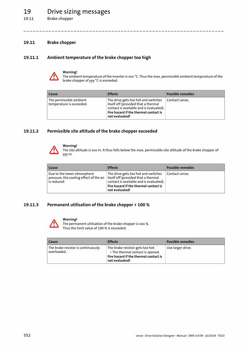
19 Drive sizing messages19.11 Brake chopper
_ _ _ _ _ _ _ _ _ _ _ _ _ _ _ _ _ _ _ _ _ _ _ _ _ _ _ _ _ _ _ _ _ _ _ _ _ _ _ _ _ _ _ _ _ _ _ _ _ _ _ _ _ _ _ _ _ _ _ _ _ _ _ _
19.11 Brake chopper
19.11.1 Ambient temperature of the brake chopper too high
19.11.2 Permissible site altitude of the brake chopper exceeded
19.11.3 Permanent utilisation of the brake chopper > 100 %
Warning!The ambient temperature of the inverter is xxx °C. Thus the max. permissible ambient temperature of the brake chopper of yyy °C is exceeded.
Cause Effects Possible remedies
The permissible ambient temperature is exceeded.
The drive gets too hot and switches itself off (provided that a thermal contact is available and is evaluated).Fire hazard if the thermal contact is not evaluated!
Contact Lenze.
Warning!The site altitude is xxx m. It thus falls below the max. permissible site altitude of the brake chopper of yyy m.
Cause Effects Possible remedies
Due to the lower atmospheric pressure, the cooling effect of the air is reduced.
The drive gets too hot and switches itself off (provided that a thermal contact is available and is evaluated).Fire hazard if the thermal contact is not evaluated!
Contact Lenze.
Warning!The permanent utilisation of the brake chopper is xxx %.Thus the limit value of 100 % is exceeded.
Cause Effects Possible remedies
The brake resistor is continuously overloaded.
The brake resistor gets too hot.• The thermal contact is opened.
Fire hazard if the thermal contact is not evaluated!
Use larger drive.
552 Lenze · Drive Solution Designer · Manual · DMS 4.9 EN · 10/2019 · TD23

19 Drive sizing messages19.11 Brake chopper
_ _ _ _ _ _ _ _ _ _ _ _ _ _ _ _ _ _ _ _ _ _ _ _ _ _ _ _ _ _ _ _ _ _ _ _ _ _ _ _ _ _ _ _ _ _ _ _ _ _ _ _ _ _ _ _ _ _ _ _ _ _ _ _
19.11.4 Utilisation >100 %, regarding the peak braking power
19.11.5 Regenerative power is not dissipated safely
Warning!The max. utilisation of the brake chopper is xxx %. Thus the limit value of 100 % is exceeded.
Cause Effects Possible remedies
The actual peak braking power per brake chopper is too high.
An overvoltage message is activated within the inverter.
• Use larger drive.• Generate a DC-bus system and
use multiple brake choppers of the devices in the DC-bus system if required. Observe the respective Hardware Manual!
Warning!The dissipation of the regenerative power is not guaranteed.
Cause Effects Possible remedies
A hoist drive generates regenerative power during the lowering operation that has to be dissipated by the inverter.Lowering operation has not been configured in the DSD.
Hoist sags.DC-bus operation may also generate situations in which regenerative power cannot be absorbed by other drives.
• Use electrical braking components.
• Use regenerative power supply modules.
Lenze · Drive Solution Designer · Manual · DMS 4.9 EN · 10/2019 · TD23 553

19 Drive sizing messages19.12 Brake resistor
_ _ _ _ _ _ _ _ _ _ _ _ _ _ _ _ _ _ _ _ _ _ _ _ _ _ _ _ _ _ _ _ _ _ _ _ _ _ _ _ _ _ _ _ _ _ _ _ _ _ _ _ _ _ _ _ _ _ _ _ _ _ _ _
19.12 Brake resistor
19.12.1 Resulting brake resistance too low
19.12.2 Permanent utilisation of the equivalent resistance > 100 %
19.12.3 Max. utilisation of the equivalent resistance is >100 %
Warning!The resulting equivalent resistance is xxx Ohm. Thus the value falls below the minimum permissible brake resistance on the brake transistor of yyy Ohm.
Cause Effects Possible remedies
The value falls below the minimum permissible resistance.
The brake chopper is overloaded. • Use different resistor.• Select different resistor
interconnection.• Increase number of the brake
choppers.
Brake resistor selection ( 404)
Warning!The permanent utilisation of the equivalent resistance is xxx %.Thus the limit value of 100 % is exceeded.
Cause Effects Possible remedies
The resistor is overloaded with regard to the continuous braking power.
The inverter indicates overvoltage.Drive moves in an uncontrolled way!
• Use different resistor.• Use different resistor
interconnection (series connection).
Brake resistor selection ( 404)
Warning!The max. utilisation of the equivalent resistance is xxx %.Thus the limit value of 100 % is exceeded.
Cause Effects Possible remedies
The required peak braking power is too high.
The brake resistor is overheated.Fire hazard!
• Select longer braking times.• Use resistor with higher peak
braking power.• Connect several brake resistor so
that a higher peak braking power is possible.
554 Lenze · Drive Solution Designer · Manual · DMS 4.9 EN · 10/2019 · TD23

19 Drive sizing messages19.12 Brake resistor
_ _ _ _ _ _ _ _ _ _ _ _ _ _ _ _ _ _ _ _ _ _ _ _ _ _ _ _ _ _ _ _ _ _ _ _ _ _ _ _ _ _ _ _ _ _ _ _ _ _ _ _ _ _ _ _ _ _ _ _ _ _ _ _
19.12.4 Max. permissible resistance value is exceeded
19.12.5 Thermal time constant of the brake resistor is too small
19.12.6 Temperature monitoring for the built-in/attached brake resistor is activated
Note!The resulting brake resistance is > 220 Ohms.The inverter may shut off due to overvoltage.Select resistance value between 180 and 220 Ohms.
Cause Effects Possible remedies
The max. permissible resistance has been exceeded.
Due to overvoltage, the inverter switches off.
• The drive will not be braked to standstill at the deceleration ramp anymore.
Select brake resistor with a resistance between 180 and 220 Ohm.
Warning!The brake resistor has a thermal time constant <120 s.In case of an uncoordinated DC-bus connection, the time constant must be >120 s.DSD cannot carry out a safe check of the brake resistor.
Cause Effects Possible remedies
With an uncoordinated multi-axis system, only brake resistors with thermal time constant >120 s are permissible.
The brake resistor overheats.Fire hazard!
Select a brake resistor with a higher thermal time constant.
Warning!The temperature monitoring function for the built-in/attached brake resistor is activated.Do not use built-in/attached brake resistor! The device may be destroyed!
Cause Effects Possible remedies
For the built-in/attached brake resistor, an additional temperature monitoring mode is calculated in the device. This temperature monitoring function responds.
The device may be destroyed. • Use of the built-in/attached brake resistor is not permissible.
• Use external brake resistor.
Lenze · Drive Solution Designer · Manual · DMS 4.9 EN · 10/2019 · TD23 555

19 Drive sizing messages19.12 Brake resistor
_ _ _ _ _ _ _ _ _ _ _ _ _ _ _ _ _ _ _ _ _ _ _ _ _ _ _ _ _ _ _ _ _ _ _ _ _ _ _ _ _ _ _ _ _ _ _ _ _ _ _ _ _ _ _ _ _ _ _ _ _ _ _ _
19.12.7 Check internal brake resistors
19.12.8 Utilisation of the brake resistor is >yyy %
Note!We recommend an additional check of the utilisation for the internal brake resistors.
Cause Effects Possible remedies
DSD checks the utilisation of the internal brake resistors according to algorithms for external resistors.
The brake resistors can overheat. Additionally let the utilisation be checked by the Lenze support.
Note!The utilisation of the brake resistor selected is xxx %.If the utilisation is >yyy %, select a more powerful brake resistor.
Cause Effects Possible remedies
With the roller conveyor, the brake resistor may be prestressed by vibrations due to control processes without a braking process taking place.
With the brake resistor, operation of the Lenze Smart Motor is restricted.
Select brake resistor with a greater power reserve.
556 Lenze · Drive Solution Designer · Manual · DMS 4.9 EN · 10/2019 · TD23

19 Drive sizing messages19.13 User motor
_ _ _ _ _ _ _ _ _ _ _ _ _ _ _ _ _ _ _ _ _ _ _ _ _ _ _ _ _ _ _ _ _ _ _ _ _ _ _ _ _ _ _ _ _ _ _ _ _ _ _ _ _ _ _ _ _ _ _ _ _ _ _ _
19.13 User motor
19.13.1 Limited check of the user motor
19.13.2 No options available for the user motor
19.13.3 Configure gearbox mounting flange for user motor
Note!DSD is only able to check the user motor to a limited extent. The drive dimensioning is based on the general rules for checking Lenze components.Check the motor according to the guidelines of the manufacturer.
Cause Effects Possible remedies
Construction data of user motors are not known. DSD is not able to carry out manufacturer-specific checks.
Limit values may be exceeded. The motor may be thermally overloaded.
• Check the motor according to the guidelines of the manufacturer.
• Have the motor checked by the manufacturer.
Note!No product options are available for the user motor.Contact the motor manufacturer.
Cause Effects Possible remedies
Product options for user motors are not available in DSD.
Selection of product options is not possible.
Contact the manufacturer of the motor.
Note!You have combined a user motor with a Lenze gearbox.The motor geometry must comply with the gearbox mounting flange.Enter the required data in the "Assignment of mounting flange" dimensioning step.
Cause Effects Possible remedies
The required data was not entered. The motor cannot be mounted to the selected gearbox.
Enter the required data in the Assignment of mounting flange dimensioning step.
Lenze · Drive Solution Designer · Manual · DMS 4.9 EN · 10/2019 · TD23 557

20 Feedback, help & support20.1 Acquisition of application data
_ _ _ _ _ _ _ _ _ _ _ _ _ _ _ _ _ _ _ _ _ _ _ _ _ _ _ _ _ _ _ _ _ _ _ _ _ _ _ _ _ _ _ _ _ _ _ _ _ _ _ _ _ _ _ _ _ _ _ _ _ _ _ _
20 Feedback, help & support
Your responsible Lenze sales department supports you with regard to all questions concerning theoperation of the DSD and the drive dimensioning.
20.1 Acquisition of application data
In order to develop the DSD continuously and target-oriented, the program contains a Acquisitionof application data. The acquisition of application data provides answers to the following importantquestions:
• Which applications are used and how intensively?
• Which auxiliary tools are used and how intensively?
• Which drive components are used for which applications?
In the Lenze setting the usage data is acquired automatically. Every three months the data istransferred to the Lenze DSD server. The precondition for this is an established Internet connection.
The data for acquisition of application data is also saved locally on your PC in the "sent" and"outbox" directories under "Documents and settings\<User name>\User data\Lenze\DSDV3.x.x.x\user_data\mail".
• If there is an Internet connection, copies of the data transmitted are stored in the "sent" directory.
• If there is no Internet connection, the data to be transmitted are stored in the "outbox" directory.• At the next program start, the DSD will try to send these data again. Delete the files in the
"outbox" directory if the DSD is not to send these data.• When the data have been transmitted successfully, copies of the data transmitted are stored
in the "sent" directory.• Ask your responsible Lenze sales department if you want to send files from the "outbox"
directory to Lenze via e-mail.
Note!
The acquisition of application data does not save or transmit personal data! The data to be transmitted can be viewed before they are sent.• Please carry out the acquisition of application data regularly.• Read the data protection notice at http://www.Lenze.com.
558 Lenze · Drive Solution Designer · Manual · DMS 4.9 EN · 10/2019 · TD23

20 Feedback, help & support20.1 Acquisition of application data
_ _ _ _ _ _ _ _ _ _ _ _ _ _ _ _ _ _ _ _ _ _ _ _ _ _ _ _ _ _ _ _ _ _ _ _ _ _ _ _ _ _ _ _ _ _ _ _ _ _ _ _ _ _ _ _ _ _ _ _ _ _ _ _
Altering settings for the acquisition of application data
• Open the Settings dialog with the command ToolsSettings.
• In the selection field Acquisition of application data the setting can be altered:• Acquire automatically (every three months)• Acquire on request• No, do not acquire
Settings ( 42)
Lenze · Drive Solution Designer · Manual · DMS 4.9 EN · 10/2019 · TD23 559

21 Glossary
_ _ _ _ _ _ _ _ _ _ _ _ _ _ _ _ _ _ _ _ _ _ _ _ _ _ _ _ _ _ _ _ _ _ _ _ _ _ _ _ _ _ _ _ _ _ _ _ _ _ _ _ _ _ _ _ _ _ _ _ _ _ _ _
21 Glossary
A
Drive analysis
Output end Side to which a load is attached.
Drive end Side to which a motor is attached.
B
Braking during operation Repeated braking from full speed, preferably used for uncontrolled drives.
Motion profile, user-definable There are different options to create a motion profile:
• Graphical creation of the motion profile in the MotionDesigner• Values can be optimised numerically.
• Creation of the motion profile by importing the operating points.
Motion profile, predefined according to the operating mode
Entry of the motion via a predefined motion profile, based on the standardisedoperating modes S1, S2, S3, or S6. The times and direction of movement canbe adapted.
Resistance to motion Auxiliary quantity for combining linear guides and wheel-controlled systemsin one value.
Brake chopper Electrical brake unit, additionally requiring an external brake resistor.
Braking unit See brake chopper.
D
Continuous braking power Power that can be continuously dissipated by the brake system.
Continuous rated curve Thermal characteristic curve for continuous operation.
Continuous power Power that can be dissipated by the inverter in continuous operation if astandard useful life is required.
Derating Decrease of rated values under specific preconditions.
E
Base process power Product of the max. torque and max. speed.
Unit system Group of units of different physical quantities.
Supply power Required power received from the mains.
Energy efficiency
Energy Performance Certificate
Single axis project
F
Travelling resistance Force per mass which a vehicle sets against its movement.
Window icon Button on the right end of the title bar to alter the window display, or to closethe window.
560 Lenze · Drive Solution Designer · Manual · DMS 4.9 EN · 10/2019 · TD23

21 Glossary
_ _ _ _ _ _ _ _ _ _ _ _ _ _ _ _ _ _ _ _ _ _ _ _ _ _ _ _ _ _ _ _ _ _ _ _ _ _ _ _ _ _ _ _ _ _ _ _ _ _ _ _ _ _ _ _ _ _ _ _ _ _ _ _
G
Variable-speed drive Entry of the kinematic data via a motion profile
Sliding friction Coulomb friction; generates a force opposed to the movement.
Group drive Several identical motors are supplied by one inverter and together power anapplication.
G+K Series connection of a Lenze gearbox and an additional drive element.
G: Lenze gearboxK: Additional drive element
H
Static friction Friction that has to be overcome before a relative movement between twobodies is possible.
Hyperlink Optically highlighted reference, activated via mouse-click.
I
Imperial American measuring system
Examples for imperial units: ft, lb, lbf
Actual ratio Actual gearbox ratio resulting from the ratio of the motor speed to themaximum speed of the application.
L
Load-matching factor Ratio of the load moment of inertia reduced to the motor shaft compared tothe intrinsic moment of inertia of the motor.
The load-matching factor is an important appraisal criterion for speed- orangle controlled dynamic acceleration drives.
Lenze gearbox Standard gearboxes such as g500, g700.
Lenze motor Standard motors such as m550-P, m540-P, m850, MCS, MCA, MDxMA.
M
Master project Project defining the supply and braking unit for multi-axis dimensionings.
Multi-axis project Master or slave project the inverter of which is part of a DC-bus connection.
Master projectSlave project
Menu bar Bar on the upper edge of the application window below the title bar, whichdisplays the names of menus that are opened by mouse-click.
Metric Measuring system, essentially based on SI units.
Examples for imperial units: m, kg, Nm
N
Electrical supply conditions Mains voltage, mains frequency, supply form, and number of phases.
Lenze · Drive Solution Designer · Manual · DMS 4.9 EN · 10/2019 · TD23 561

21 Glossary
_ _ _ _ _ _ _ _ _ _ _ _ _ _ _ _ _ _ _ _ _ _ _ _ _ _ _ _ _ _ _ _ _ _ _ _ _ _ _ _ _ _ _ _ _ _ _ _ _ _ _ _ _ _ _ _ _ _ _ _ _ _ _ _
P
PDF Abbreviation for "Portable Document Format", universal file format developedby the company Adobe for the exchange of electronic documents. By means ofthe Adobe® Reader® software which is available from Adobe free of charge,PDF files can be displayed and printed, irrespective of the application and theplatform used for the creation.
Internet: http://www.adobe.com/
Project comparison Comparison of the parameters of all projects open in the DSD.
SAP list of the configuration.Results for the drive analysis.
Log Statement in writing of calculation results:
• Summarised report• Scope: One page DIN A4
• Detailed report• Lenze BlueGreen Solutions
• Comparing several projects with regard to energy efficiency and amortisation
R
Feedback energy The regenerative energy to be received by the brake resistor.
Regenerative power Power that is resupplied from the motor in operation in generator mode andthat is either dispensed to the mains or to a brake resistor.
S
Slave project Project with regard to multi-axis applications, in which no dimensioning ofthe supply and braking unit is effected.
Multi-axis project
Setpoint ratio Intended gearbox ratio resulting from the ratio of the motor speed to themaximum speed of the application.
Peak braking power Power which may occur for a short time.
T
Title bar Bar on the upper edge of the application window, containing the program iconand program name on the left end as well as the window icons on the rightend.
Window icon
Disengagement time Time from the start of the release of the mechanical brake to the decrease to 10 % of the rated torque.
U
Overload capacity Ratio of the max. torque to the rated torque of a motor-inverter combination.
Uncontrolled drive Entry of the kinematic data via the standardised operating modes S1, S2, S3,S6.
Uprating Uprating of rated values under specific preconditions.
562 Lenze · Drive Solution Designer · Manual · DMS 4.9 EN · 10/2019 · TD23

21 Glossary
_ _ _ _ _ _ _ _ _ _ _ _ _ _ _ _ _ _ _ _ _ _ _ _ _ _ _ _ _ _ _ _ _ _ _ _ _ _ _ _ _ _ _ _ _ _ _ _ _ _ _ _ _ _ _ _ _ _ _ _ _ _ _ _
V
Network type Multi-axis system with i700 servo inverter or multi-axis system with ServoDrives 9400 HighLine, Inverter Drives 8400.
Engagement time In the case of mechanical brakes is composed of the deceleration time t11when the brake is activated and the rise time t12 of the braking torque.
Preview value Parameter determined in advance from the loads; can still change after theactual selection of the components.
Z
Additional drive element A dedicated gearbox or a downstream ratio to the gearbox.
Lenze · Drive Solution Designer · Manual · DMS 4.9 EN · 10/2019 · TD23 563

Index
564 Lenze · Drive Solution Designer · Manual · DMS 4.9 EN · 10/2019 · TD23
_ _ _ _ _ _ _ _ _ _ _ _ _ _ _ _ _ _ _ _ _ _ _ _ _ _ _ _ _ _ _ _ _ _ _ _ _ _ _ _ _ _ _ _ _ _ _ _ _ _ _ _ _ _ _ _ _ _ _ _ _ _ _ _
22 Index
Numbers120-Hz operation, motor 347
87-Hz operation, motor 347
9400 regenerative power supply module 400
AAcquisition of application data 558
Activating the brake 268
Additional drive element 335, 377
Additional moment of inertia 332
AKB (Application Knowledge Base) 15
Alternating load factor 372
Alternating load for toothed gearboxes 372
Alternatives 55
Ambient conditions 294
Ambient temperature, inverter 295
Ambient temperature, motor/gearbox 294
Application Knowledge Base (AKB) 15
Application notes 18
Application, qualitative requirements 497
Axial forces 357, 374
Axial gearbox, properties 305
Axial loads 492
BBearing current choke, application of 501
Belt conveyor, bulk material 151
Belt conveyor, unit load 146
Belt drive 83
Belt drive, rotating 72
Bevel gearbox, properties 305
Brake resistor, wiring several 405
Brake, holding torque 364
Brake, mechanical 360
Brake, permanent magnet 363
Brake, selection table 360
CCalculating the backing force 480
Calculating the belt mass 479
Calculating the cable mass 476
Calculating the leadscrew efficiency 484
Calculating the mass of counterweight 475
Calculating the payload 478
Calculating the uniform load mass 477
Calculator, backing force 480
Calculator, gearbox 472
Calculator, hand-held calculator 466
Calculator, inertia 469
Calculator, leadscrew efficiency 484
Calculator, line load mass 477
Calculator, mass 467
Calculator, mass of belt 479
Calculator, mass of counterweight 475
Calculator, mass of delivery volume 478
Calculator, mass of rope/cable 476
Calculator, pinion diameter 474
Calculator, travelling resistance 481
Chain conveyor 133
Changeinterdependent values 37value or selection subsequently 37
Checking the speed load 374
Checking the torque load 370
Checklist for the asynchronous machine of a user motor 459
Checklist for the synchronous machine of a user motor 461
Checklists for the drive dimensioning 53
Closing the program 40
Communication, DSD server 46
Compare project 435
Compatibility check 50
Components, DC bus 397
Continuous rated curve 342, 346
Control elements 19
Control type, inverter 380
Control types 321
Controller inhibit 268
Conventions used 17
Cooling servo motors without gearbox 502
Counterforce 268
Create project 48
Current derating, inverter 393
Customer data 49
DDC bus, components 397
Decentralised inverters, features 318
Diagrams, components 431
Dimensioning of inverters 379
Direct mounting 307
Displacement of the M-n characteristic 494
Document history 16
Drawing 28, 430
Drive analysis 435
Drive axis, electrical 301
Drive axis, mechanical 299
Drive concept 302
Drive dimensioning, restrictions 488
Drive element, additional 377
Drive system, optimisation of the energy efficiency 423
DSD server, communication 46
Dynamic reserves 442

Lenze · Drive Solution Designer · Manual · DMS 4.9 EN · 10/2019 · TD23 565
Index
_ _ _ _ _ _ _ _ _ _ _ _ _ _ _ _ _ _ _ _ _ _ _ _ _ _ _ _ _ _ _ _ _ _ _ _ _ _ _ _ _ _ _ _ _ _ _ _ _ _ _ _ _ _ _ _ _ _ _ _ _ _ _ _
Ee.l.c.b. 497
EASY Product Finder 14
Electrical supply system 293
E-mail to Lenze 568
Emergency-off scenarios 500
Enclosure, brake resistor 407
Encoder selection table 394
Endurance strength 370
Energy efficiency, cost comparison 417
Energy efficiency, cost-cutting potentials 424
Energy efficiency, diagrams project comparison 416
Energy efficiency, Energy Performance Certificate 419
Energy efficiency, Lenze BlueGreen Solutions 415
Energy efficiency, optimising the drive system 423
Energy Performance Certificate 419
Energy saving function, Lenze Smart Motor 335
Enter toolbar, kinematics 243
Evaluating results 429
FFan 180
Fatique strength 370
Feedback 394, 558
Feedback systems, types 395
Feedback to Lenze 568
Field weakening 488
Field weakening in case of the winding drive 348
Filter in the motor cable 500
Flange mounting 307
Frequency inverter, features 313
Function elements 19
GGearbox 370
Gearbox, ambient temperature 294
Gearbox, axial gearbox properties 305
Gearbox, bevel gearbox properties 305
Gearbox, direct mounting or flange mounting 307
Gearbox, gearbox oil 375
Gearbox, lubricant 375
Gearbox, M-n characteristic 369
Gearbox, mounting position 333
Gearbox, selection 366
Gearbox, shaft sealing ring 375
Gearbox, thermal utilisation 374
Geared motor, preselection 330
General drive 171
Glossary 560
Group drives 498
HHelp 558
Highly dynamic applications 489
Hoist drive with counterweight 122
Hoist drive with counterweight, mass in motion 128
Hoist drive without counterweight 113
Hoist drives, without feedback 323
Holding brake 362
Holding brake with safety function 493
Holding brake, permanent magnet holding brake 363
Holding brake, with safety function 362
Holding torque, brake 364
HTL encoder 396
Ii700 power supply module 402
Import project 51
Importing a user motor 447
Importing M-n-operating points 184
Information regarding the validity 16
Input area 34
Inverter at the e.l.c.b. 497
Inverter selection 381
Inverter with an integrated EMC filter 380
Inverter, ambient temperature 295
Inverter, control mode 380
Inverter, control modes 321
Inverter, decentralised inverter properties 318
Inverter, determining utilisation values 383
Inverter, dimensioning criteria 383
Inverter, frequency inverter properties 313
Inverter, motor control 380
Inverter, motor output 379
Inverter, preselection 379
Inverter, servo inverter properties 316
Inverter, switching frequency 379
Inverter, thermal utilisation 385
Inverter, type 379
IP enclosure, brake resistor 407
KKeyboard commands 39
LLanguage 41
Layout of the safety information 18
Layout of the safety instructions 18
Lenze BlueGreen Solutions 415
Lenze gearbox 370
Lenze Smart Motor, energy saving function 335
Lenze Smart Motor, M-n characteristic 345
Lenze Smart Motor, selection table 343
level support 558
Licencing and contractual conditions 13
Load the motion profile 250
Load-matching factor 351

Index
566 Lenze · Drive Solution Designer · Manual · DMS 4.9 EN · 10/2019 · TD23
_ _ _ _ _ _ _ _ _ _ _ _ _ _ _ _ _ _ _ _ _ _ _ _ _ _ _ _ _ _ _ _ _ _ _ _ _ _ _ _ _ _ _ _ _ _ _ _ _ _ _ _ _ _ _ _ _ _ _ _ _ _ _ _
Log 435
MMains frequency 293
Mains voltage 293
Managing user motors, activating the function 447
Managing user motors, changing designations 450
Managing user motors, commands in the context menu 450
Managing user motors, comment 458
Managing user motors, electrical settings 454
Managing user motors, mechanical settings 452
Managing user motors, settings for accessories 458
Managing user motors, toolbar 449
Managing user motors, user interface 448
Mass in motion 128
Mass of payload 268
Maximum permissible motor cable length 495
MCS, cooling via mounting flange 502
Menu bar 20
Mismatch 351
M-n characteristic for the Lenze Smart Motor 345
M-n characteristic, gearbox 369
Motion design 240
Motion profile, application instructions 279
Motion profile, linear 282
Motion profile, non-linear 283
Motion profile, predefined according to the operating mode 286
Motion profile, rewinder 221
Motion profile, sin²shaped 285
Motion profile, S-shaped 284
MotionDesigner 486
Motor cable 500
Motor cable length 495
Motor cable, switching 500
Motor control when detecting the motor temperature 501
Motor control, encoderless 323
Motor control, inverter 380
Motor for winding drive 311
Motor M-n characteristic 340
Motor mounting flange, assigning 358
Motor mounting flange, standard 358
Motor selection 337
Motor selection table 337
Motor utilisation 350
Motor, 120-Hz operation 347
Motor, 87-Hz operation 347
Motor, ambient temperature 294
Motor, asynchronous servo motor properties 309
Motor, direct mounting or flange mounting 307
Motor, impacts of the switching frequency 495
Motor, M-n characteristic 340
Motor, synchronous servo motor properties 308
Motor, thermal utilisation 350
Motor, three-phase AC motor properties 310
Mounting position, gearbox 333
Multi-axis application 190, 191
Multiturn SinCos encoder 396
NNotes 37
OOmega belt drive 83
Online documentation 463
Open project 50
Open the project in the ProjectViewer 52
Operating mode in accordance with VDE 0530 286
Operating time, average daily 335
Operation of inverters on the earth-leakage circuit breaker 497
Overcurrent operationi510 391i550 391i950 servo inverter 388Inverter Drives 8400 390
Overcurrent operation - i700 servo inverters 387
Overcurrent operation, Servo Drives 9400 HighLine 386
PPhysical coefficients 485
Plan project 53
Power system 293
Prepare project 53
Preselection of the geared motor 330
Preselection of the inverter 379
Product Finder 14
Product options for Lenze products 413
Project comparison 59, 435
Project information 49
Project, compatibility check 50
ProjectViewer 52
Pump 176
RRack drive 94
Radial forces 357, 374
Radial loads 492
Repeated load cycle for toothed gearboxes 372
Report, detailed 436
Report, summarised 435
Reports 435
Reserves with regard to the drive dimensioning 442
Resolver 396
Restrictions of the drive dimensioning 488
Result tree 33, 434
Rewinder, motion profile 221
Right-angle gearbox, properties 305

Lenze · Drive Solution Designer · Manual · DMS 4.9 EN · 10/2019 · TD23 567
Index
_ _ _ _ _ _ _ _ _ _ _ _ _ _ _ _ _ _ _ _ _ _ _ _ _ _ _ _ _ _ _ _ _ _ _ _ _ _ _ _ _ _ _ _ _ _ _ _ _ _ _ _ _ _ _ _ _ _ _ _ _ _ _ _
Roller conveyor 139
Rotary table drive 173
SS1 characteristics 342, 346
Safety information 18
Saturation effects in the motor 491
Save motion profile 251
Save project 52
Select Lenze Smart Motor 343
Selection help, products for drive systems (without winders) 326
Selection help, products for winding drive systems 327, 329
Selection table 394
Selection table for Lenze Smart Motor 343
Selection table, electromechanical brake 360
Selection table, gearbox 366
Selection table, inverter 381
Service brake 362, 493
Service packs and updates 15
Servo inverter, properties 316
Servo motors, features 309
Settings 42
sin²-shaped motion profile 285
SinCos encoder 396
Single-axis application 189
Singleturn SinCos encoder 396
Site altitude 296
Speed reserves 443
Spindle drive 100
Spring-applied brake 363
S-shaped motion profile 284
SSI absolute value encoder 396
Standstill phase 268
Static strength 370
Stationary reserves 442
Supply system 293
Switching frequency, impacts on the motor 495
Switching frequency, inverter 379
Switching in the motor cable 500
Synchronous drive - single roll 158
Synchronous drive of squeegees 164
Synchronous servo motor, features 308
System disturbances 497
TTables of values 485
Target group 16
Temperature detection with motor temperature sensor 501
Terms and conditions 13
Thermal protection of the motor acc. to UL 502
Thermal protection of the motor, acc. to UL 502
Three-phase AC motor properties 310
Toolbar 25
Torque 67
TTL encoder 396
UUL approved 18
Ul, permanent load at low motor speeds 502
Undervoltages, impact on operational performance 489
UR approved 18
User interface 19
User motor, checklist for the asynchronous machine 459
User motor, checklist for the synchronous machine 461
User motor, display in the project 303
User motor, features 447
User motor, M-n characteristic 453
User motor, mounting flange motor standard 451
User motor, technology 451
User, equivalent circuit diagram 455
Using the Lenze Smart Motor 71
Utilisation, gearbox 374
Utilisation, inverter 385
VVertical conveyors, without feedback 323
Voltage 293
WWheel drive 106
Winding drive, dimensioning strategies 210
Winding drive, field weakening 348
Wöhler characteristic 370

568 Lenze · Drive Solution Designer · Manual · DMS 4.9 EN · 10/2019 · TD23
_ _ _ _ _ _ _ _ _ _ _ _ _ _ _ _ _ _ _ _ _ _ _ _ _ _ _ _ _ _ _ _ _ _ _ _ _ _ _ _ _ _ _ _ _ _ _ _ _ _ _ _ _ _ _ _ _ _ _ _ _ _ _ _
Your opinion is important to us!We have created these instructions to the best of our knowledge withthe objective of providing you with the best possible support for ourproduct.
Perhaps we haven't achieved this goal in all points. If you notice this,please send us your suggestions and your comments in a short e-mailto:
Thank you for your support.
Your Lenze documentation team

Lenze · Drive Solution Designer · Manual · DMS 4.9 EN · 10/2019 · TD23 569
_ _ _ _ _ _ _ _ _ _ _ _ _ _ _ _ _ _ _ _ _ _ _ _ _ _ _ _ _ _ _ _ _ _ _ _ _ _ _ _ _ _ _ _ _ _ _ _ _ _ _ _ _ _ _ _ _ _ _ _ _ _ _ _

L
Drive Solution Designer · Manual · EDSDSD · 13587395 · DMS 4.9 EN · 10/2019 · TD23
Lenze Automation GmbHPostfach 10 13 52, D-31763 HamelnHans-Lenze-Str. 1, D-31855 AerzenGermanyHR Hannover B 205381
+49 5154 82-0 +49 5154 82-2800 [email protected] www.lenze.com
ServiceLenze Service GmbHBreslauer Straße 3, D-32699 ExtertalGermany
008000 24 46877 (24 h helpline) +49 5154 82-1112 [email protected]