software configuration
TRANSCRIPT

Cisco 3900 Series, 2900 Series, and 1900 Series Integrated Services Routers Generation 2 Software Configuration Guide
Americas HeadquartersCisco Systems, Inc.170 West Tasman DriveSan Jose, CA 95134-1706 USAhttp://www.cisco.comTel: 408 526-4000
800 553-NETS (6387)Fax: 408 527-0883
Text Part Number: OL-21850-01

THE SPECIFICATIONS AND INFORMATION REGARDING THE PRODUCTS IN THIS MANUAL ARE SUBJECT TO CHANGE WITHOUT NOTICE. ALL STATEMENTS, INFORMATION, AND RECOMMENDATIONS IN THIS MANUAL ARE BELIEVED TO BE ACCURATE BUT ARE PRESENTED WITHOUT WARRANTY OF ANY KIND, EXPRESS OR IMPLIED. USERS MUST TAKE FULL RESPONSIBILITY FOR THEIR APPLICATION OF ANY PRODUCTS.
THE SOFTWARE LICENSE AND LIMITED WARRANTY FOR THE ACCOMPANYING PRODUCT ARE SET FORTH IN THE INFORMATION PACKET THAT SHIPPED WITH THE PRODUCT AND ARE INCORPORATED HEREIN BY THIS REFERENCE. IF YOU ARE UNABLE TO LOCATE THE SOFTWARE LICENSE OR LIMITED WARRANTY, CONTACT YOUR CISCO REPRESENTATIVE FOR A COPY.
The Cisco implementation of TCP header compression is an adaptation of a program developed by the University of California, Berkeley (UCB) as part of UCB’s public domain version of the UNIX operating system. All rights reserved. Copyright © 1981, Regents of the University of California.
NOTWITHSTANDING ANY OTHER WARRANTY HEREIN, ALL DOCUMENT FILES AND SOFTWARE OF THESE SUPPLIERS ARE PROVIDED “AS IS” WITH ALL FAULTS. CISCO AND THE ABOVE-NAMED SUPPLIERS DISCLAIM ALL WARRANTIES, EXPRESSED OR IMPLIED, INCLUDING, WITHOUT LIMITATION, THOSE OF MERCHANTABILITY, FITNESS FOR A PARTICULAR PURPOSE AND NONINFRINGEMENT OR ARISING FROM A COURSE OF DEALING, USAGE, OR TRADE PRACTICE.
IN NO EVENT SHALL CISCO OR ITS SUPPLIERS BE LIABLE FOR ANY INDIRECT, SPECIAL, CONSEQUENTIAL, OR INCIDENTAL DAMAGES, INCLUDING, WITHOUT LIMITATION, LOST PROFITS OR LOSS OR DAMAGE TO DATA ARISING OUT OF THE USE OR INABILITY TO USE THIS MANUAL, EVEN IF CISCO OR ITS SUPPLIERS HAVE BEEN ADVISED OF THE POSSIBILITY OF SUCH DAMAGES.
CCDE, CCENT, CCSI, Cisco Eos, Cisco HealthPresence, Cisco IronPort, the Cisco logo, Cisco Nurse Connect, Cisco Pulse, Cisco SensorBase, Cisco StackPower, Cisco StadiumVision, Cisco TelePresence, Cisco Unified Computing System, Cisco WebEx, DCE, Flip Channels, Flip for Good, Flip Mino, Flipshare (Design), Flip Ultra, Flip Video, Flip Video (Design), Instant Broadband, and Welcome to the Human Network are trademarks; Changing the Way We Work, Live, Play, and Learn, Cisco Capital, Cisco Capital (Design), Cisco:Financed (Stylized), Cisco Store, Flip Gift Card, and One Million Acts of Green are service marks; and Access Registrar, Aironet, AllTouch, AsyncOS, Bringing the Meeting To You, Catalyst, CCDA, CCDP, CCIE, CCIP, CCNA, CCNP, CCSP, CCVP, Cisco, the Cisco Certified Internetwork Expert logo, Cisco IOS, Cisco Lumin, Cisco Nexus, Cisco Press, Cisco Systems, Cisco Systems Capital, the Cisco Systems logo, Cisco Unity, Collaboration Without Limitation, Continuum, EtherFast, EtherSwitch, Event Center, Explorer, Follow Me Browsing, GainMaker, iLYNX, IOS, iPhone, IronPort, the IronPort logo, Laser Link, LightStream, Linksys, MeetingPlace, MeetingPlace Chime Sound, MGX, Networkers, Networking Academy, PCNow, PIX, PowerKEY, PowerPanels, PowerTV, PowerTV (Design), PowerVu, Prisma, ProConnect, ROSA, SenderBase, SMARTnet, Spectrum Expert, StackWise, WebEx, and the WebEx logo are registered trademarks of Cisco Systems, Inc. and/or its affiliates in the United States and certain other countries.
All other trademarks mentioned in this document or website are the property of their respective owners. The use of the word partner does not imply a partnership relationship between Cisco and any other company. (0910R)
Any Internet Protocol (IP) addresses used in this document are not intended to be actual addresses. Any examples, command display output, and figures included in the document are shown for illustrative purposes only. Any use of actual IP addresses in illustrative content is unintentional and coincidental.
Cisco 3900 Series, 2900 Series, 1900 Series Integrated Services Routers Software Configuration Guide © 2009-2010 Cisco Systems, Inc. All rights reserved.

Preface
This preface describes the objectives, audience, organization, conventions of this guide, and the references that accompany this document set. The following sections are provided:
• Objectives, page iii
• Audience, page iii
• Organization, page iii
• Conventions, page v
• Related Documentation, page vi
• Searching Cisco Documents, page vii
ObjectivesThis guide provides an overview and explains how to configure the various features for the Cisco 1900 series, Cisco 2900 series, and Cisco 3900 series integrated services routers generation 2 (ISR G2). Some information may not apply to your particular router model.
AudienceThis document is written for experienced technical workers who install, monitor, and troubleshoot routers under a service contract, or who work for an information technology (IT) department.
OrganizationThis guide is divided into three parts:
• Part 1—Configuring the Router
• Part 2—Configuring the Access Point
• Part 3—Appendix
iiiCisco 3900 Series, 2900 Series, and 1900 Series Integrated Services Routers Software Configuration Guide
OL-21850-01

Preface
Part 1 Configuring the Router DescriptionModule 1 Overview of Hardware and Software Describes new hardware and software features
in this release, features by platform, new slots, common ports, and getting started tasks.
Module 2 Basic Router Configuration Describes how to perform the basic router configuration, interface configuration, and routing configuration.
Module 3 Configuring Backup Data Lines and Remote Management
Describes how to configure backup interfaces, dial backup, and remote management.
Module 4 Configuring Power Efficiency Management
Describes the hardware and software power efficiency management features on the router. See Cisco EnergyWise Configuration Guide for information about configuring power efficiency management on modules and interface.
Module 5 Configuring Security Features Describes how to configure security features.
Module 6 Unified Communications on Cisco Integrated Services Routers
Describes voice application services that are supported on these routers.
Module 7 Configuring Next-Generation High-Density PVDM3 Modules
Describes how to configure the new next-generation PVDM31 installed on your router.
Module 8 Multi-Gigabit Fabric Communication
Describes how modules and interface cards inter-communicate using the MGF2 on the router.
Module 9 Upgrading the Cisco IOS Software Describes how to upgrade the Cisco IOS software image on the router or the access point.
Part 2 Configuring the Access Point DescriptionModule 1 Wireless Overview Describes the autonomous image and recovery
image shipped on the Cisco 1941W access point flash. Explains the default autonomous mode and Cisco Unified mode.
Module 2 Configuring the Wireless Device Describes how to configure the autonomous wireless device, how to upgrade the autonomous software to Cisco Unified software, and how to configure a Unified wireless device.
Module 3 Configuring the Radio Settings Describes how to configure the radio settings for the wireless device.
Module 4 Administering the Wireless Device Describes many administration tasks for the wireless device.
Part 3 Appendix DescriptionAppendix A Cisco IOS CLI for Initial
ConfigurationDescribes how to perform the initial configuration of the router using the Cisco IOS CLI, and additional configuration procedures for the router.
ivCisco 3900 Series, 2900 Series, and 1900 Series Integrated Services Routers Software Configuration Guide
OL-21850-01
Preface
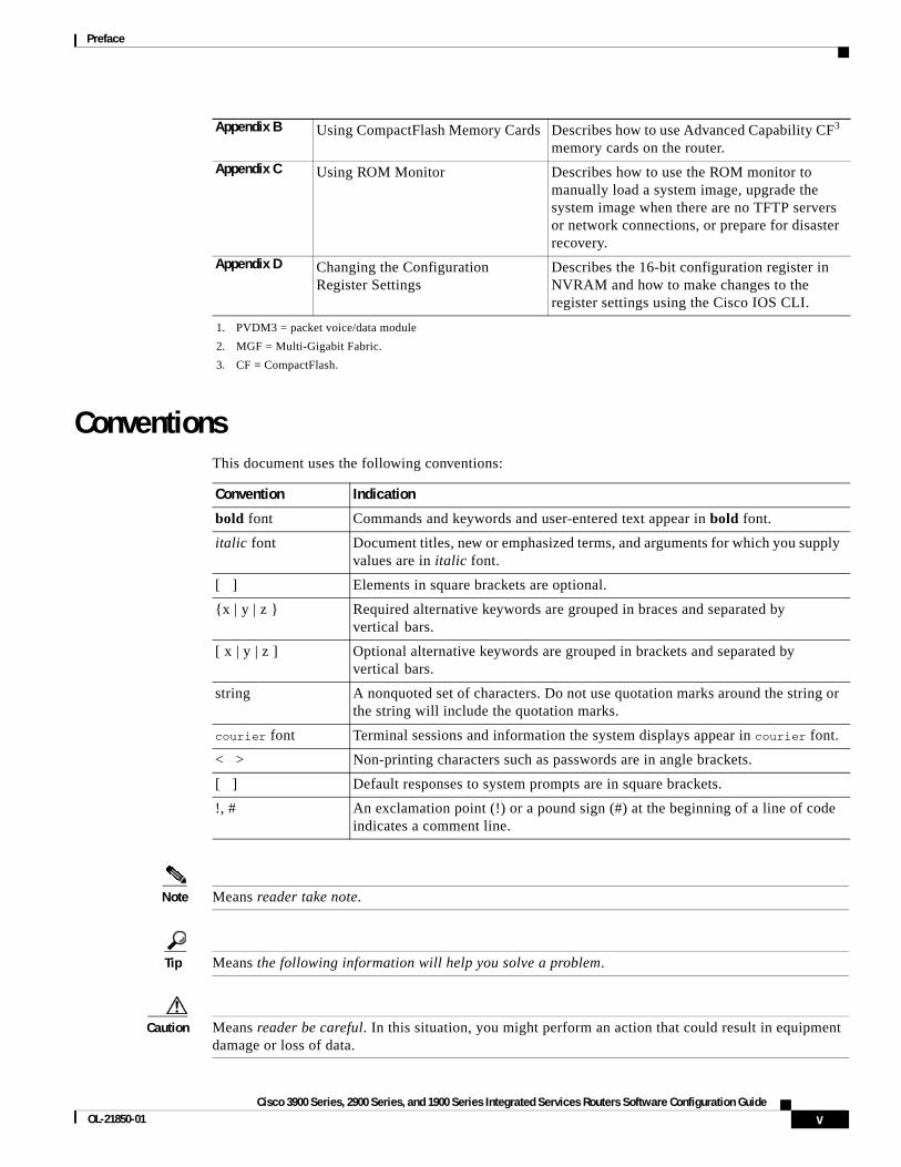
ConventionsThis document uses the following conventions:
Note Means reader take note.
Tip Means the following information will help you solve a problem.
Caution Means reader be careful. In this situation, you might perform an action that could result in equipment damage or loss of data.
Appendix B Using CompactFlash Memory Cards Describes how to use Advanced Capability CF3 memory cards on the router.
Appendix C Using ROM Monitor Describes how to use the ROM monitor to manually load a system image, upgrade the system image when there are no TFTP servers or network connections, or prepare for disaster recovery.
Appendix D Changing the Configuration Register Settings
Describes the 16-bit configuration register in NVRAM and how to make changes to the register settings using the Cisco IOS CLI.
1. PVDM3 = packet voice/data module
2. MGF = Multi-Gigabit Fabric.
3. CF = CompactFlash.
Convention Indication
bold font Commands and keywords and user-entered text appear in bold font.
italic font Document titles, new or emphasized terms, and arguments for which you supply values are in italic font.
[ ] Elements in square brackets are optional.
{x | y | z } Required alternative keywords are grouped in braces and separated by vertical bars.
[ x | y | z ] Optional alternative keywords are grouped in brackets and separated by vertical bars.
string A nonquoted set of characters. Do not use quotation marks around the string or the string will include the quotation marks.
courier font Terminal sessions and information the system displays appear in courier font.
< > Non-printing characters such as passwords are in angle brackets.
[ ] Default responses to system prompts are in square brackets.
!, # An exclamation point (!) or a pound sign (#) at the beginning of a line of code indicates a comment line.
vCisco 3900 Series, 2900 Series, and 1900 Series Integrated Services Routers Software Configuration Guide
OL-21850-01

Preface
Timesaver Means the described action saves time. You can save time by performing the action described in the paragraph.
Warning Means reader be warned. In this situation, you might perform an action that could result in bodily injury.
Related DocumentationIn addition to the Cisco 1900 series, Cisco 2900 series, and Cisco 3900 series ISR Software Configuration Guide (this document), the following reference guides are included:
Type of Document Links
Hardware • Read Me First for the Cisco 1900 Series, 2900 Series, and 3900 Series Integrated Services Routers.
• Regulatory Compliance and Safety Information for Cisco 1900 Series Integrated Services Routers.
• Cisco 2900 Series and 3900 Series Integrated Services Routers Hardware Installation Guide
• Cisco 1900 Series Integrated Services Routers Hardware Installation Guide.
• Cisco Modular Access Router Cable Specifications
• Installing, Replacing, and Upgrading Components in Cisco Modular Access Routers and Integrated Services Routers
• Overview of Cisco Network Modules for Cisco Access Routers
• Cisco Interface Cards for Cisco Access Routers
• Installing Cisco Network Modules in Cisco Access Routers
• Installing Cisco Interface Cards in Cisco Access Routers
Regulatory Compliance • Declarations of Conformity and Regulatory Information for Cisco Access Products with 802.11a/b/g and 802.11b/g Radios
• Regulatory Compliance and Safety Information for Cisco 2900 Series Integrated Services Routers
• Regulatory Compliance and Safety Information for Cisco 3900 Series Integrated Services Routers
Software Activation • Software Activation for Cisco Integrated Services Routers
• Cisco IOS Software Activation Configuration Guide
Configuration • Cisco CP Express User’s Guide
viCisco 3900 Series, 2900 Series, and 1900 Series Integrated Services Routers Software Configuration Guide
OL-21850-01

Preface
Searching Cisco DocumentsTo search a Hyper Text Markup Language (HTML) document using a web browser, press Ctrl-F (Windows) or Cmd-F (Apple). In most browsers, the option to search whole words only, invoke case sensitivity, or search forward and backward is also available.
To search a PDF document in Adobe Reader, use the basic Find toolbar (Ctrl-F) or the Full Reader Search window (Shift-Ctrl-F). Use the Find toolbar to find words or phrases within a specific document. Use the Full Reader Search window to search multiple PDF files simultaneously and to change case sensitivity and other options. Adobe Reader’s online help has more information about how to search PDF documents.
Cisco Internet Operating System Software (IOS)
Cisco IOS software release 15.0 is the next IOS release following the Cisco IOS 12.4(24)T release. For information about new features in Cisco IOS software release 15.0, see the Cisco IOS software pages at Cisco.com.
Go here to read a product bulletin that specifies the software feature sets available for Cisco 1900, 2900 and 3900 Series Integrated Services Routers in release 15.0. It also issues recommendations for Flash and DRAM memory configuration. http://www.cisco.com/en/US/prod/collateral/iosswrel/ps8802/ps5460/ product_bulletin_c25-566278_ps10537_Products_Bulletin.html
Wireless • Cisco IOS Command Reference for Cisco Aironet Access Points and Bridges, versions 12.4(10b) JA and 12.3(8) JEC
• Wireless LAN Controllers
• Unified Wireless LAN Access Points
Voice • Cisco IOS Voice Port Configuration Guide
• SCCP Controlled Analog (FXS) Ports with Supplementary Features in Cisco IOS Gateways
Modules • Cisco SRE Internal Service Modules Configuration Guide.
• Cisco Services Ready Engine Configuration Guide.
• Cisco SRE Service Modules Configuration Guide.
• Connecting Cisco EtherSwitch Service Modules to the Network.
• Cisco EtherSwitch Service Modules Feature Guide.
Type of Document Links
viiCisco 3900 Series, 2900 Series, and 1900 Series Integrated Services Routers Software Configuration Guide
OL-21850-01

Preface
viiiCisco 3900 Series, 2900 Series, and 1900 Series Integrated Services Routers Software Configuration Guide
OL-21850-01

P A R T 1
Configuring the Router


Overview of the Hardware and Software
The Cisco 3900 series, 2900 series, and 1900 series integrated services routers (ISRs) offer secure, wire-speed delivery of concurrent data, voice, and video services. The modular design of these routers provides maximum flexibility, allowing you to configure your router to meet evolving needs.
The routers offer features such as hardware-based virtual private network (VPN) encryption acceleration, intrusion-protection and firewall functions, and optional integrated call processing and voice mail. A wide variety of legacy network modules and interfaces, service modules (SMs), internal services modules (ISMs), next-generation packet voice/data modules (PVDM3), Services Performance Engines (SPEs), high-density interfaces for a wide range of connectivity requirements, and sufficient performance and slot density for future network expansion requirements and advanced applications are available.
Power-saving hardware and software features are incorporated throughout the series. These routers provide access to the multi-gigabit fabric, which provides a connection between switch ports without using up external ports. The logical Gigabit Ethernet (GE) interface on the router connects external and internal modules through the backplane for LAN and WAN switching. Software feature upgrades are provided through software licensing.
The following sections describe the Cisco 3900 series, 2900 series, and 1900 series ISRs:
• New Features in this Release, page 2
• New Features by Platform, page 4
• New Slots, page 4
• New Slots and Ports by Platform, page 5
• Common Ports, page 6
• Licensing, page 6
• Getting Started, page 7
Americas Headquarters:Cisco Systems, Inc., 170 West Tasman Drive, San Jose, CA 95134-1706 USA

Overview of the Hardware and Software New Features in this Release
New Features in this ReleaseNew features in this release are described in Table 1.
Table 1 New Features
Feature Description
Services Performance Engine
SPEs1 are modular motherboards on Cisco 3900 series ISRs. The SPE houses PVDM3 slots, system memory slots, and the ISM slot. The SPE provides a modular approach to system upgrades. You simply slide out the SPE from the router to replace internal modules, or upgrade the SPE to improve router performance. See Cisco 2900 series and 3900 series Integrated Services Routers Hardware Installation Guide for instructions.
Cryptographic Engine Accelerator
Cisco 3900 series routers with either Services Performance Engine 200 or Services Performance Engine 250 have an onboard cryptographic accelerator that is shared between SSLVPN and IPSec. By default, acceleration of SSL is disabled so IPSec performance is maximized.
See the “Configuring Security Features” section on page 1 in this guide for information about enabling the SSLVPN feature.
USB Console Cisco 3900 series, 2900 series, and 1900 series ISRs provide an additional mechanism for configuring the system through a USB2 serial console port. The traditional RJ-45 serial console port is also available.
Power Management Some modules and interface cards that are inserted in new slots provide hardware and software power management features described below:
• High efficiency AC power supplies
• Electrical components with built-in power saving features, such as RAM select and clock gating
• Ability to disable unused clocks to modules and peripherals
• Ability to power down unused modules and put peripherals into a reset state, put front panel ports and unused internal components in a shutdown or reset state
Advanced Capability CompactFlash
Cisco 3900 series, 2900 series, and 1900 series ISRs use Advanced Capability CF3 memory to store the system image, configuration files, and some software data files.
SFP/Gigabit Ethernet Port Cisco 2921, Cisco 2951 and Cisco 3900 Series routers have an SFP/Gigabit Ethernet port that supports copper and fiber concurrent connections. Media can be configured for failover redundancy when the network goes down. For more information, see the “Configuring Backup Data Lines and Remote Management” section on page 1.
2Cisco 3900 Series, 2900 Series, and 1900 Series Integrated Services Routers Software

Overview of the Hardware and Software New Features in this Release
New Modules and Interface Cards
Cisco 3900 series, 2900 series, and 1900 series ISRs introduce the following new modules and interface cards, which are inserted in the following new router slots:
• EHWIC
• PVDM3
• ISM
• SM
Note See the router’s product page at Cisco.com for a complete list of supported modules and interfaces.
Multi-Gigabit Fabric Communication
Cisco 3900 series, 2900 series, and 1900 series ISRs use a MGF4 for the new modules and interface cards to inter-communicate on the router. Legacy modules that support Cisco HIMI5 also support MGF to inter-communicate on the router. Next generation module drivers integrate with the MGF to perform port configurations, configure packet flow, and control traffic buffering. All configurations are performed from the module-side, which may or may not lead to changes on the MGF. For more information, see the “Configuring Multi-Gigabit Fabric Communication” section on page 1.
Integrated Application Services Features
Cisco 3900 series, 2900 series, and 1900 series ISRs offer integrated security features and voice features.
• See the “Configuring Security Features” section on page 1
• See the “Unified Communications on Cisco Integrated Services Routers” section on page 1
1. SPE = Services Performance Engine
2. USB = universal serial bus
3. CF = CompactFlash
4. MGF = multi-gigabit fabric
5. HIMI = High-Speed Intrachassis Module Interconnect
Table 1 New Features (continued)
Feature Description
3Cisco 3900 Series, 2900 Series, and 1900 Series Integrated Services Routers Software
OL-21850-01

Overview of the Hardware and Software New Features by Platform
New Features by PlatformTable 2 shows new feature support by platform.
New SlotsCisco 3900 series, 2900 series, and 1900 series ISRs have introduced new slots on the chassis. The first column in Table 3 lists the new slot names. The second column lists the corresponding old slot names. Modules previously inserted in the old slots now insert in the new slots with the help of an adapter card.
For instance, network modules (NMs), enhanced network modules (NMEs), and extension voice modules (EVMs) use an adapter, or carrier card, to insert into the SM slot. See your router’s hardware installation guide for adapter information.
Table 2 New Features in this Release by Platform
Features 1941 1941W 2901 2911 2921 2951 3925 3925E 3945 3945E
Services Performance Engine N N N N N N Y Y Y Y
Cryptographic Engine Acceleration
N N N N N N Y1
1. Must have Services Performance Engine 200 installed in the router.
Y Y2
2. Must have Services Performance Engine 250 installed in the router.
Y
USB Serial Console Y Y Y Y Y Y Y Y Y Y
Power Management Y Y Y Y Y Y Y Y Y Y
New Module and Interface Card Features
Y Y Y Y Y Y Y Y Y Y
Advanced Capability CompactFlash
Y Y Y Y Y Y Y Y Y Y
SFP/Gigabit Ethernet Port N N N N Y Y Y Y Y Y
Multi-Gigabit Fabric Communication
Y Y Y Y Y Y Y Y Y Y
Integrated Application Services Y3
3. Does not support Voice application services.
Y4
4. Does not support Voice application services. Includes embedded wireless access point that supports Cisco Unified Wireless Architecture.
Y Y Y Y Y Y Y Y
Table 3 New Slot Names and Old Slot Names
New Slot Names Old Slot Names
EHWIC HWIC,HWIC-DW, WIC, VWIC, VIC
ISM AIM1
1. AIM is not supported in this release. See your hardware installation guide for more information.
PVDM3 PVDM
SM NM, NME, EVM
SPE2
2. The SPE is available only on the Cisco 3900 series ISRs.
—
4Cisco 3900 Series, 2900 Series, and 1900 Series Integrated Services Routers Software
Overview of the Hardware and Software New Slots and Ports by Platform
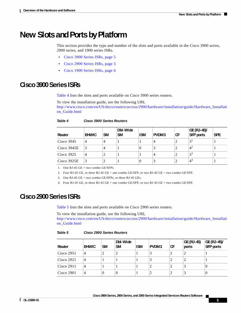
New Slots and Ports by PlatformThis section provides the type and number of the slots and ports available in the Cisco 3900 series, 2900 series, and 1900 series ISRs.
• Cisco 3900 Series ISRs, page 5
• Cisco 2900 Series ISRs, page 5
• Cisco 1900 Series ISRs, page 6
Cisco 3900 Series ISRsTable 4 lists the slots and ports available on Cisco 3900 series routers.
To view the installation guide, see the following URL http://www.cisco.com/en/US/docs/routers/access/2900/hardware/installation/guide/Hardware_Installation_Guide.html
Cisco 2900 Series ISRsTable 5 lists the slots and ports available on Cisco 2900 series routers.
To view the installation guide, see the following URL http://www.cisco.com/en/US/docs/routers/access/2900/hardware/installation/guide/Hardware_Installation_Guide.html
Table 4 Cisco 3900 Series Routers
Router EHWIC SM Dbl-Wide SM ISM PVDM3 CF
GE (RJ-45)/ SFP ports SPE
Cisco 3945 4 4 1 1 4 2 31
1. One RJ-45 GE + two combo GE/SFPs.
1
Cisco 3945E 3 4 1 0 3 2 42
2. Four RJ-45 GE, or three RJ-45 GE + one combo GE/SFP, or two RJ-45 GE + two combo GE/SFP.
1
Cisco 3925 4 2 1 1 4 2 33
3. One RJ-45 GE + two combo GE/SFPs, or three RJ-45 GEs.
1
Cisco 3925E 3 2 1 0 3 2 44
4. Four RJ-45 GE, or three RJ-45 GE + one combo GE/SFP, or two RJ-45 GE + two combo GE/SFP.
1
Table 5 Cisco 2900 Series Routers
Router EHWIC SM Dbl-Wide SM ISM PVDM3 CF
GE (RJ-45) ports
GE (RJ-45)/ SFP ports
Cisco 2951 4 2 2 1 3 2 2 1
Cisco 2921 4 1 1 1 3 2 2 1
Cisco 2911 4 1 1 1 2 2 3 0
Cisco 2901 4 0 0 1 2 2 3 0
5Cisco 3900 Series, 2900 Series, and 1900 Series Integrated Services Routers Software
OL-21850-01

Overview of the Hardware and Software Common Ports
Cisco 1900 Series ISRsTable 6 lists the slots and ports available on Cisco 1900 series routers. To view the installation guide, see the following URL http://www.cisco.com/en/US/docs/routers/access/1900/hardware/installation/guide/1900_HIG.html
Common PortsThe following ports are common among Cisco 3900 series, 2900 series, and 1900 series routers:
• Gigabit Ethernet RJ45—Ports available through an RJ45 connector.
• Gigabit Ethernet RJ45/SFP—Ports available through RJ45- SFP connectors. Connection supports fail-over if the secondary connection goes down.
• RS232 Aux—Supports modem control lines and remote administration for box-to-box redundancy applications.
• RS232 Serial Console—Supports modem control lines and remote administration of the router with the proprietary cable shipped in the box.
• Type A USB 2.0—Supports USB-based flash memory sticks, security tokens, and USB-compliant devices.
• Type B mini-port USB Serial Console—Supports modem control lines and remote administration of the router using a type B USB-compliant cable.
LicensingCisco 3900 series, 2900 series, and 1900 series ISRs support Cisco IOS software entitlement. Your router is shipped with the software image and the corresponding permanent licenses for the technology packages and features that you specified preinstalled. You do not need to activate or register the software prior to use. If you need to upgrade or install a new technology package or feature see Software Activation on Integrated Services Router,
http://www.cisco.com/en/US/docs/routers/access/sw_activation/SA_on_ISR.html.
Table 6 Cisco 1900 Series ISR Routers
Router EHWIC SM Dbl-Wide SM ISM PVDM3 WLAN CF
GE (RJ-45) ports
Cisco 1941 2 0 0 1 0 0 2 2
Cisco 1941W 2 0 0 0 0 1 2 2
6Cisco 3900 Series, 2900 Series, and 1900 Series Integrated Services Routers Software
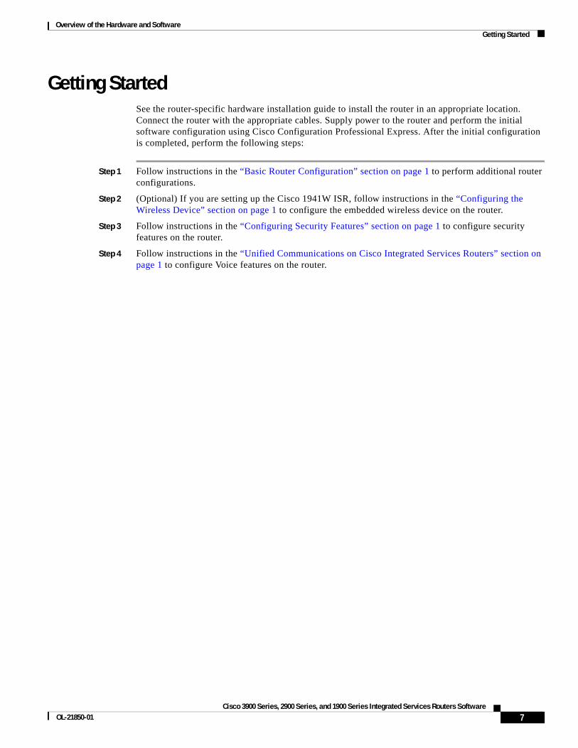
Overview of the Hardware and Software Getting Started
Getting StartedSee the router-specific hardware installation guide to install the router in an appropriate location. Connect the router with the appropriate cables. Supply power to the router and perform the initial software configuration using Cisco Configuration Professional Express. After the initial configuration is completed, perform the following steps:
Step 1 Follow instructions in the “Basic Router Configuration” section on page 1 to perform additional router configurations.
Step 2 (Optional) If you are setting up the Cisco 1941W ISR, follow instructions in the “Configuring the Wireless Device” section on page 1 to configure the embedded wireless device on the router.
Step 3 Follow instructions in the “Configuring Security Features” section on page 1 to configure security features on the router.
Step 4 Follow instructions in the “Unified Communications on Cisco Integrated Services Routers” section on page 1 to configure Voice features on the router.
7Cisco 3900 Series, 2900 Series, and 1900 Series Integrated Services Routers Software
OL-21850-01
Overview of the Hardware and Software Getting Started
CCDE, CCENT, CCSI, Cisco Eos, Cisco HealthPresence, Cisco IronPort, the Cisco logo, Cisco Nurse Connect, Cisco Pulse, Cisco SensorBase, Cisco StackPower, Cisco StadiumVision, Cisco TelePresence, Cisco Unified Computing System, Cisco WebEx, DCE, Flip Channels, Flip for Good, Flip Mino, Flipshare (Design), Flip Ultra, Flip Video, Flip Video (Design), Instant Broadband, and Welcome to the Human Network are trademarks; Changing the Way We Work, Live, Play, and Learn, Cisco Capital, Cisco Capital (Design), Cisco:Financed (Stylized), Cisco Store, Flip Gift Card, and One Million Acts of Green are service marks; and Access Registrar, Aironet, AllTouch, AsyncOS, Bringing the Meeting To You, Catalyst, CCDA, CCDP, CCIE, CCIP, CCNA, CCNP, CCSP, CCVP, Cisco, the Cisco Certified Internetwork Expert logo, Cisco IOS, Cisco Lumin, Cisco Nexus, Cisco Press, Cisco Systems, Cisco Systems Capital, the Cisco Systems logo, Cisco Unity, Collaboration Without Limitation, Continuum, EtherFast, EtherSwitch, Event Center, Explorer, Follow Me Browsing, GainMaker, iLYNX, IOS, iPhone, IronPort, the IronPort logo, Laser Link, LightStream, Linksys, MeetingPlace, MeetingPlace Chime Sound, MGX, Networkers, Networking Academy, PCNow, PIX, PowerKEY, PowerPanels, PowerTV, PowerTV (Design), PowerVu, Prisma, ProConnect, ROSA, SenderBase, SMARTnet, Spectrum Expert, StackWise, WebEx, and the WebEx logo are registered trademarks of Cisco Systems, Inc. and/or its affiliates in the United States and certain other countries.
All other trademarks mentioned in this document or website are the property of their respective owners. The use of the word partner does not imply a partnership relationship between Cisco and any other company. (0910R)
Any Internet Protocol (IP) addresses used in this document are not intended to be actual addresses. Any examples, command display output, and figures included in the document are shown for illustrative purposes only. Any use of actual IP addresses in illustrative content is unintentional and coincidental. © 2009-2010 Cisco Systems, Inc. All rights reserved.
8Cisco 3900 Series, 2900 Series, and 1900 Series Integrated Services Routers Software

Basic Router Configuration
This module provides configuration procedures for Cisco 3900 series, 2900 series, and 1900 series integrated services routers (ISRs). It also includes configuration examples and verification steps whenever possible.
Note See Appendix A, “Cisco IOS CLI for Initial Configuration” for information on how to perform the initial configuration using the Cisco Internet Operating System (IOS) command line interface on Cisco 3900 series, 2900 series, and 1900 series integrated services routers.
Basic Configuration
• Default Configuration, page 2
• Configuring Global Parameters, page 3
Interface Configuration
• Interface Ports, page 5
• Configuring Gigabit Ethernet Interfaces, page 6
• Configuring Wireless LAN Interfaces, page 7
• Configuring Interface Card and Module Interfaces, page 7
• Configuring a Loopback Interface, page 7
Routing Configuration
• Configuring Command-Line Access, page 9
• Configuring Static Routes, page 11
• Configuring Dynamic Routes, page 12
Americas Headquarters:Cisco Systems, Inc., 170 West Tasman Drive, San Jose, CA 95134-1706 USA
Basic Router Configuration Default Configuration
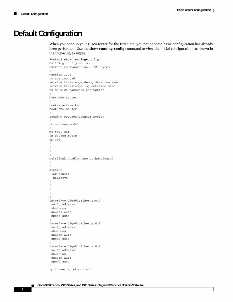
Default ConfigurationWhen you boot up your Cisco router for the first time, you notice some basic configuration has already been performed. Use the show running-config command to view the initial configuration, as shown in the following example.
Router# show running-configBuilding configuration...Current configuration : 723 bytes!version 12.4no service padservice timestamps debug datetime msecservice timestamps log datetime msecno service password-encryption!hostname Router!boot-start-markerboot-end-marker!logging message-counter syslog!no aaa new-model!no ipv6 cefip source-routeip cef!!! !multilink bundle-name authenticated!!archive log config hidekeys!!!!!interface GigabitEthernet0/0 no ip address shutdown duplex auto speed auto!interface GigabitEthernet0/1 no ip address shutdown duplex auto speed auto!interface GigabitEthernet0/2 no ip address shutdown duplex auto speed auto!ip forward-protocol nd
2Cisco 3900 Series, 2900 Series, and 1900 Series Integrated Services Routers Software
Basic Router Configuration Configuring Global Parameters
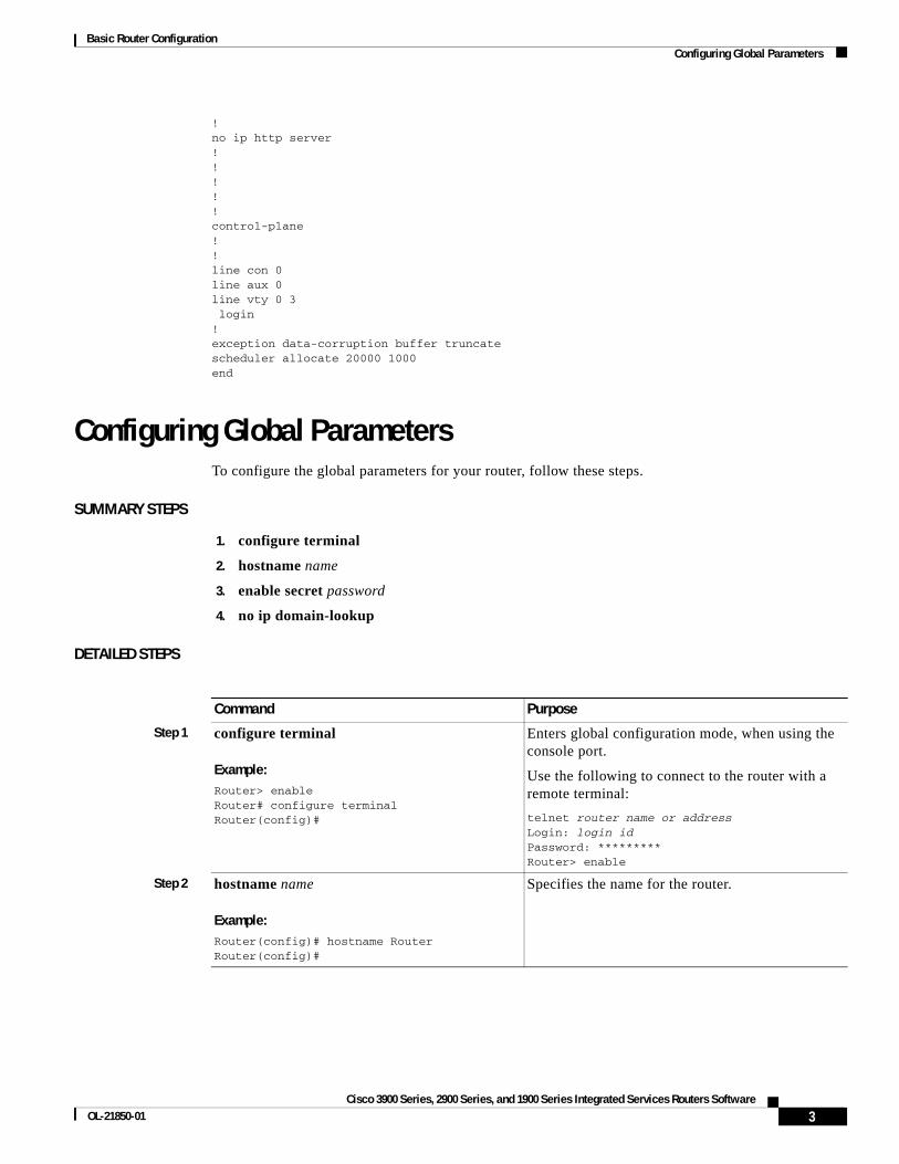
!no ip http server!!!!!control-plane!!line con 0line aux 0line vty 0 3 login!exception data-corruption buffer truncatescheduler allocate 20000 1000end
Configuring Global ParametersTo configure the global parameters for your router, follow these steps.
SUMMARY STEPS
1. configure terminal
2. hostname name
3. enable secret password
4. no ip domain-lookup
DETAILED STEPS
Command Purpose
Step 1 configure terminal
Example:Router> enableRouter# configure terminalRouter(config)#
Enters global configuration mode, when using the console port.
Use the following to connect to the router with a remote terminal:
telnet router name or addressLogin: login idPassword: *********Router> enable
Step 2 hostname name
Example:Router(config)# hostname RouterRouter(config)#
Specifies the name for the router.
3Cisco 3900 Series, 2900 Series, and 1900 Series Integrated Services Routers Software
OL-21850-01

Basic Router Configuration Configuring I/O Memory Allocation
For complete information on global parameter commands, see the Cisco IOS Release configuration guide documentation set.
Configuring I/O Memory AllocationTo reallocate the percentage of DRAM in use for I/O memory and processor memory on Cisco 3925E and Cisco 3945E routers, use the memory-size iomem i/o-memory-percentage command in global configuration mode. To revert to the default memory allocation, use the no form of this command. This procedure enables smartinit.
Tip We recommend that you configure the memory-size iomem below 25%. Any value above 25% should be used only for enhancing IPSec performance.
When you specify the percentage of I/O memory in the command line, the processor memory automatically acquires the remaining percentage of DRAM memory.
Example
The following example allocates 25% of the DRAM memory to I/O memory and the remaining 75% to processor memory:
Router#config tEnter configuration commands, one per line. End with CNTL/Z.Router(config)# memory-size iomem 5IO memory size too small: minimum IO memory size is 201M Router(config)# Router(config)# memory-size iomem ?<5-50> percentage of DRAM to use for I/O memory: 5, 10, 15, 20, 25, 30, 40, 50
Router(config)# memory-size iomem 25Smart-init will be disabled and new I/O memory size will take effect upon reload.Router(config)# end
Step 3 enable secret password
Example:Router(config)# enable secret cr1ny5hoRouter(config)#
Specifies an encrypted password to prevent unauthorized access to the router.
Step 4 no ip domain-lookup
Example:Router(config)# no ip domain-lookup Router(config)#
Disables the router from translating unfamiliar words (typos) into IP addresses.
Command Purpose
Syntax Description
i/o-memory-percentage The percentage of DRAM allocated to I/O memory. The values permitted are 5, 10, 15, 20, 25, 30, 40, and 50. A minimum of 201 MB of memory is required for I/O memory.
4Cisco 3900 Series, 2900 Series, and 1900 Series Integrated Services Routers Software
Basic Router Configuration Interface Ports
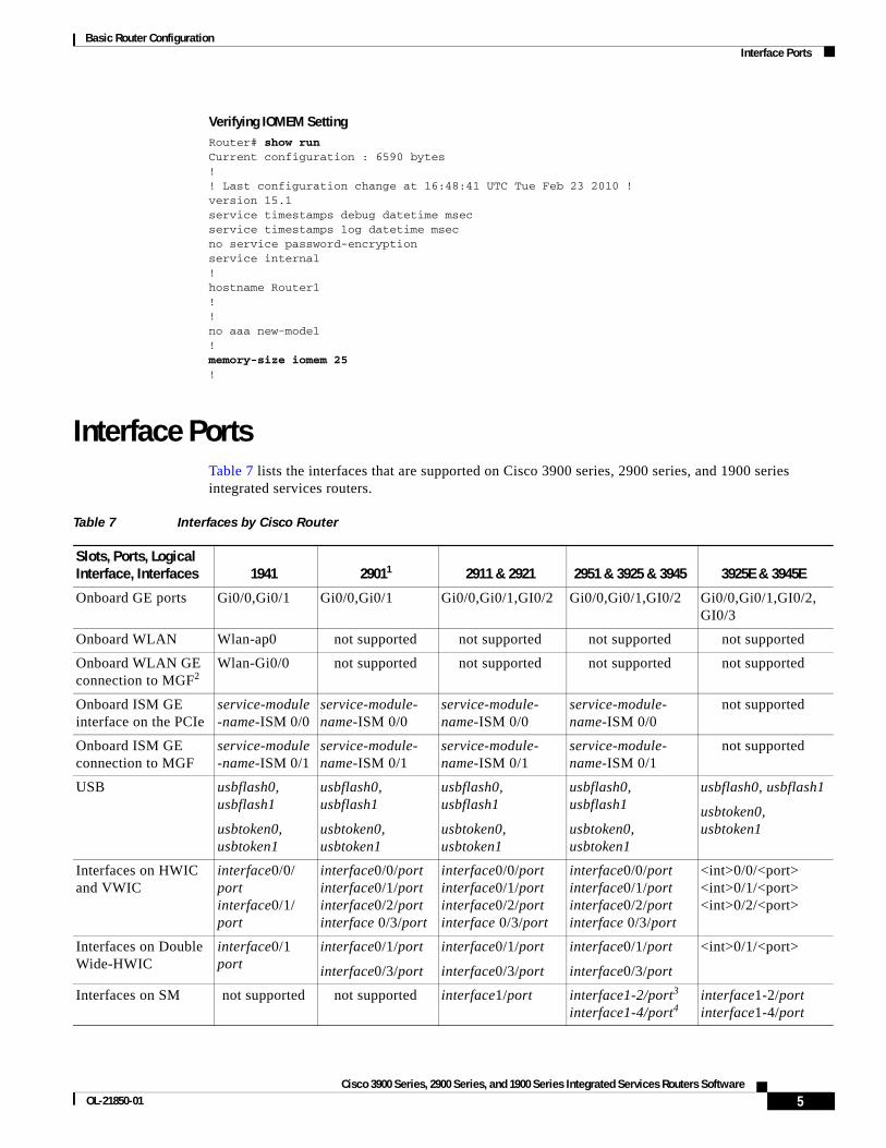
Verifying IOMEM SettingRouter# show runCurrent configuration : 6590 bytes!! Last configuration change at 16:48:41 UTC Tue Feb 23 2010 !version 15.1service timestamps debug datetime msecservice timestamps log datetime msecno service password-encryptionservice internal!hostname Router1!!no aaa new-model!memory-size iomem 25!
Interface PortsTable 7 lists the interfaces that are supported on Cisco 3900 series, 2900 series, and 1900 series integrated services routers.
Table 7 Interfaces by Cisco Router
Slots, Ports, Logical Interface, Interfaces 1941 29011 2911 & 2921 2951 & 3925 & 3945 3925E & 3945E
Onboard GE ports Gi0/0,Gi0/1 Gi0/0,Gi0/1 Gi0/0,Gi0/1,GI0/2 Gi0/0,Gi0/1,GI0/2 Gi0/0,Gi0/1,GI0/2, GI0/3
Onboard WLAN Wlan-ap0 not supported not supported not supported not supported
Onboard WLAN GE connection to MGF2
Wlan-Gi0/0 not supported not supported not supported not supported
Onboard ISM GE interface on the PCIe
service-module-name-ISM 0/0
service-module- name-ISM 0/0
service-module- name-ISM 0/0
service-module- name-ISM 0/0
not supported
Onboard ISM GE connection to MGF
service-module-name-ISM 0/1
service-module- name-ISM 0/1
service-module- name-ISM 0/1
service-module- name-ISM 0/1
not supported
USB usbflash0, usbflash1
usbtoken0, usbtoken1
usbflash0, usbflash1
usbtoken0, usbtoken1
usbflash0, usbflash1
usbtoken0, usbtoken1
usbflash0, usbflash1
usbtoken0, usbtoken1
usbflash0, usbflash1
usbtoken0, usbtoken1
Interfaces on HWIC and VWIC
interface0/0/ port interface0/1/ port
interface0/0/port interface0/1/port interface0/2/port interface 0/3/port
interface0/0/port interface0/1/port interface0/2/port interface 0/3/port
interface0/0/port interface0/1/port interface0/2/port interface 0/3/port
<int>0/0/<port> <int>0/1/<port> <int>0/2/<port>
Interfaces on Double Wide-HWIC
interface0/1 port
interface0/1/port
interface0/3/port
interface0/1/port
interface0/3/port
interface0/1/port
interface0/3/port
<int>0/1/<port>
Interfaces on SM not supported not supported interface1/port interface1-2/port3 interface1-4/port4
interface1-2/port interface1-4/port
5Cisco 3900 Series, 2900 Series, and 1900 Series Integrated Services Routers Software
OL-21850-01

Basic Router Configuration Configuring Gigabit Ethernet Interfaces
Configuring Gigabit Ethernet InterfacesTo manually define onboard Gigabit Ethernet (GE) interfaces, follow these steps, beginning in global configuration mode.
SUMMARY STEPS
1. interface gigabitethernet slot/port
2. ip address ip-address mask
3. no shutdown
4. exit
DETAILED STEPS
Interfaces on Double Wide-SM
not supported not supported not supported interface 2/port5 interface4/port6
interface 2/port interface 4/port
Interfaces HWIC on SM
Interfaces VWIC on SM
not supported not supported interface1wic-slot/port
interface1-2/wic- slot/port7
interface1-4/wic- slot/port8
interface1-2/wic- slot/port interface1-4/wic- slot/port
1. On the Cisco 2901 router, the numbering format for configuring an asynchronous interface is 0/slot/port. To configure the line associated with an asynchronous interface, simply use the interface number to specify the asynchronous line. For example, line 0/1/0 specifies the line associated with interface serial 0/1/0 on a WIC-2A/S in slot 1. Similarly, line 0/2/1 specifies the line associated with interface async 0/2/1 on a WIC-2AM in slot 2.
2. MGF = multi-gigabit fabric
3. Applies only to Cisco 2951, Cisco 3925, and Cisco 3925E routers.
4. Applies only to Cisco 3945 and Cisco 3945E routers.
5. Applies only to Cisco 2951, Cisco 3925, and Cisco 3925E routers.
6. Applies only to Cisco 3945 and Cisco 3945E routers.
7. Applies only to Cisco 2951, Cisco 3925, and Cisco 3925E routers.
8. Applies only to Cisco 3945 and Cisco 3945E routers.
Table 7 Interfaces by Cisco Router (continued)
Slots, Ports, Logical Interface, Interfaces 1941 29011 2911 & 2921 2951 & 3925 & 3945 3925E & 3945E
Command Purpose
Step 1 interface gigabitethernet slot/port
Example:Router(config)# interface gigabitethernet 0/1Router(config-if)#
Enters the configuration mode for a Gigabit Ethernet interface on the router.
Step 2 ip address ip-address mask
Example:Router(config-if)# ip address 192.168.12.2 255.255.255.0Router(config-if)#
Sets the IP address and subnet mask for the specified GE interface.
6Cisco 3900 Series, 2900 Series, and 1900 Series Integrated Services Routers Software
Basic Router Configuration Configuring Wireless LAN Interfaces
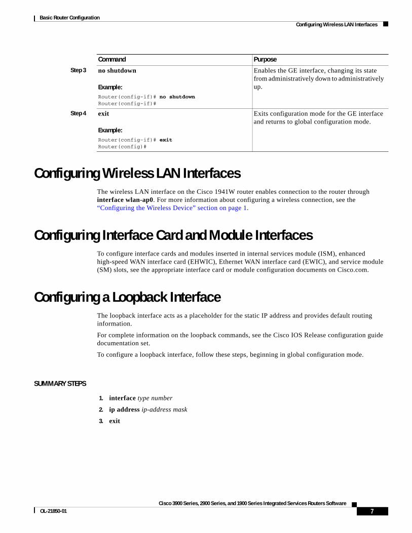
Configuring Wireless LAN InterfacesThe wireless LAN interface on the Cisco 1941W router enables connection to the router through interface wlan-ap0. For more information about configuring a wireless connection, see the “Configuring the Wireless Device” section on page 1.
Configuring Interface Card and Module InterfacesTo configure interface cards and modules inserted in internal services module (ISM), enhanced high-speed WAN interface card (EHWIC), Ethernet WAN interface card (EWIC), and service module (SM) slots, see the appropriate interface card or module configuration documents on Cisco.com.
Configuring a Loopback InterfaceThe loopback interface acts as a placeholder for the static IP address and provides default routing information.
For complete information on the loopback commands, see the Cisco IOS Release configuration guide documentation set.
To configure a loopback interface, follow these steps, beginning in global configuration mode.
SUMMARY STEPS
1. interface type number
2. ip address ip-address mask
3. exit
Step 3 no shutdown
Example:Router(config-if)# no shutdownRouter(config-if)#
Enables the GE interface, changing its state from administratively down to administratively up.
Step 4 exit
Example:Router(config-if)# exitRouter(config)#
Exits configuration mode for the GE interface and returns to global configuration mode.
Command Purpose
7Cisco 3900 Series, 2900 Series, and 1900 Series Integrated Services Routers Software
OL-21850-01
Basic Router Configuration Configuring a Loopback Interface
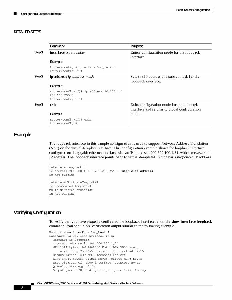
DETAILED STEPS
Example
The loopback interface in this sample configuration is used to support Network Address Translation (NAT) on the virtual-template interface. This configuration example shows the loopback interface configured on the gigabit ethernet interface with an IP address of 200.200.100.1/24, which acts as a static IP address. The loopback interface points back to virtual-template1, which has a negotiated IP address.
!interface loopback 0ip address 200.200.100.1 255.255.255.0 (static IP address)ip nat outside!interface Virtual-Template1ip unnumbered loopback0no ip directed-broadcastip nat outside!
Verifying Configuration
To verify that you have properly configured the loopback interface, enter the show interface loopback command. You should see verification output similar to the following example.
Router# show interface loopback 0Loopback0 is up, line protocol is up Hardware is Loopback Internet address is 200.200.100.1/24 MTU 1514 bytes, BW 8000000 Kbit, DLY 5000 usec, reliability 255/255, txload 1/255, rxload 1/255 Encapsulation LOOPBACK, loopback not set Last input never, output never, output hang never Last clearing of "show interface" counters never Queueing strategy: fifo Output queue 0/0, 0 drops; input queue 0/75, 0 drops
Command Purpose
Step 1 interface type number
Example:Router(config)# interface Loopback 0Router(config-if)#
Enters configuration mode for the loopback interface.
Step 2 ip address ip-address mask
Example:Router(config-if)# ip address 10.108.1.1 255.255.255.0Router(config-if)#
Sets the IP address and subnet mask for the loopback interface.
Step 3 exit
Example:Router(config-if)# exitRouter(config)#
Exits configuration mode for the loopback interface and returns to global configuration mode.
8Cisco 3900 Series, 2900 Series, and 1900 Series Integrated Services Routers Software
Basic Router Configuration Configuring Command-Line Access
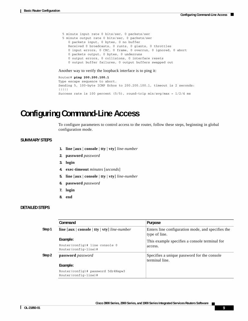
5 minute input rate 0 bits/sec, 0 packets/sec 5 minute output rate 0 bits/sec, 0 packets/sec 0 packets input, 0 bytes, 0 no buffer Received 0 broadcasts, 0 runts, 0 giants, 0 throttles 0 input errors, 0 CRC, 0 frame, 0 overrun, 0 ignored, 0 abort 0 packets output, 0 bytes, 0 underruns 0 output errors, 0 collisions, 0 interface resets 0 output buffer failures, 0 output buffers swapped out
Another way to verify the loopback interface is to ping it:
Router# ping 200.200.100.1 Type escape sequence to abort.Sending 5, 100-byte ICMP Echos to 200.200.100.1, timeout is 2 seconds:!!!!!Success rate is 100 percent (5/5), round-trip min/avg/max = 1/2/4 ms
Configuring Command-Line AccessTo configure parameters to control access to the router, follow these steps, beginning in global configuration mode.
SUMMARY STEPS
1. line [aux | console | tty | vty] line-number
2. password password
3. login
4. exec-timeout minutes [seconds]
5. line [aux | console | tty | vty] line-number
6. password password
7. login
8. end
DETAILED STEPS
Command Purpose
Step 1 line [aux | console | tty | vty] line-number
Example:Router(config)# line console 0Router(config-line)#
Enters line configuration mode, and specifies the type of line.
This example specifies a console terminal for access.
Step 2 password password
Example:Router(config)# password 5dr4Hepw3Router(config-line)#
Specifies a unique password for the console terminal line.
9Cisco 3900 Series, 2900 Series, and 1900 Series Integrated Services Routers Software
OL-21850-01
Basic Router Configuration Configuring Command-Line Access
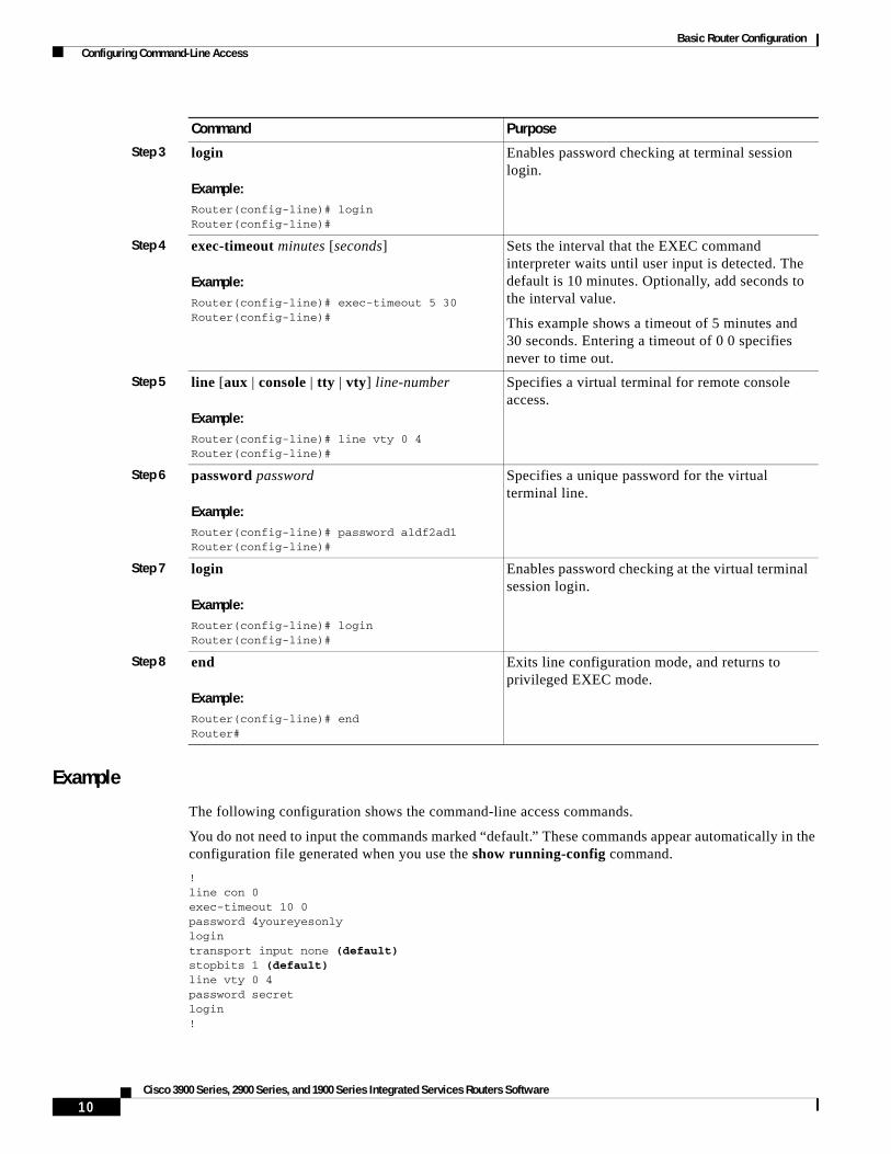
Example
The following configuration shows the command-line access commands.
You do not need to input the commands marked “default.” These commands appear automatically in the configuration file generated when you use the show running-config command.
!line con 0exec-timeout 10 0password 4youreyesonlylogintransport input none (default)stopbits 1 (default)line vty 0 4password secretlogin!
Step 3 login
Example:Router(config-line)# loginRouter(config-line)#
Enables password checking at terminal session login.
Step 4 exec-timeout minutes [seconds]
Example:Router(config-line)# exec-timeout 5 30Router(config-line)#
Sets the interval that the EXEC command interpreter waits until user input is detected. The default is 10 minutes. Optionally, add seconds to the interval value.
This example shows a timeout of 5 minutes and 30 seconds. Entering a timeout of 0 0 specifies never to time out.
Step 5 line [aux | console | tty | vty] line-number
Example:Router(config-line)# line vty 0 4Router(config-line)#
Specifies a virtual terminal for remote console access.
Step 6 password password
Example:Router(config-line)# password aldf2ad1Router(config-line)#
Specifies a unique password for the virtual terminal line.
Step 7 login
Example:Router(config-line)# loginRouter(config-line)#
Enables password checking at the virtual terminal session login.
Step 8 end
Example:Router(config-line)# endRouter#
Exits line configuration mode, and returns to privileged EXEC mode.
Command Purpose
10Cisco 3900 Series, 2900 Series, and 1900 Series Integrated Services Routers Software

Basic Router Configuration Configuring Static Routes
Configuring Static RoutesStatic routes provide fixed routing paths through the network. They are manually configured on the router. If the network topology changes, the static route must be updated with a new route. Static routes are private routes unless they are redistributed by a routing protocol.
To configure static routes, follow these steps, beginning in global configuration mode.
SUMMARY STEPS
1. ip route prefix mask {ip-address | interface-type interface-number [ip-address]}
2. end
DETAILED STEPS
Example
In the following configuration example, the static route sends out all IP packets with a destination IP address of 192.168.1.0 and a subnet mask of 255.255.255.0 on the Gigabit Ethernet interface to another device with an IP address of 10.10.10.2. Specifically, the packets are sent to the configured PVC.
You do not need to enter the command marked “(default).” This command appears automatically in the configuration file generated when you use the show running-config command.
!ip classless (default)ip route 192.168.1.0 255.255.255.0 10.10.10.2!
Command Purpose
Step 1 ip route prefix mask {ip-address | interface-type interface-number [ip-address]}
Example:Router(config)# ip route 192.168.1.0 255.255.0.0 10.10.10.2Router(config)#
Specifies the static route for the IP packets.
For details about this command and about additional parameters that can be set, see Cisco IOS IP Command Reference, Volume 2 of 4: Routing Protocols, Release 12.3
Step 2 end
Example:Router(config)# endRouter#
Exits router configuration mode, and enters privileged EXEC mode.
11Cisco 3900 Series, 2900 Series, and 1900 Series Integrated Services Routers Software
OL-21850-01

Basic Router Configuration Configuring Dynamic Routes
Verifying ConfigurationTo verify that you have properly configured static routing, enter the show ip route command and look for static routes signified by the “S.”
You should see verification output similar to the following:
Router# show ip routeCodes: C - connected, S - static, R - RIP, M - mobile, B - BGP D - EIGRP, EX - EIGRP external, O - OSPF, IA - OSPF inter area N1 - OSPF NSSA external type 1, N2 - OSPF NSSA external type 2 E1 - OSPF external type 1, E2 - OSPF external type 2 i - IS-IS, su - IS-IS summary, L1 - IS-IS level-1, L2 - IS-IS level-2 ia - IS-IS inter area, * - candidate default, U - per-user static route o - ODR, P - periodic downloaded static route
Gateway of last resort is not set
10.0.0.0/24 is subnetted, 1 subnetsC 10.108.1.0 is directly connected, Loopback0S* 0.0.0.0/0 is directly connected, FastEthernet0
Configuring Dynamic RoutesIn dynamic routing, the network protocol adjusts the path automatically, based on network traffic or topology. Changes in dynamic routes are shared with other routers in the network.
The Cisco routers can use IP routing protocols, such as Routing Information Protocol (RIP) or Enhanced Interior Gateway Routing Protocol (EIGRP), to learn routes dynamically. You can configure either of these routing protocols on your router.
• “Configuring Routing Information Protocol” section on page 12
• “Configuring Enhanced Interior Gateway Routing Protocol” section on page 14
Configuring Routing Information ProtocolTo configure the RIP routing protocol on the router, follow these steps, beginning in global configuration mode.
SUMMARY STEPS
1. router rip
2. version {1 | 2}
3. network ip-address
4. no auto-summary
5. end
12Cisco 3900 Series, 2900 Series, and 1900 Series Integrated Services Routers Software

Basic Router Configuration Configuring Dynamic Routes
DETAILED STEPS
Example
The following configuration example shows RIP version 2 enabled in IP network 10.0.0.0 and 192.168.1.0.
To see this configuration, use the show running-config command from privileged EXEC mode.
!Router# show running-configrouter rip version 2 network 10.0.0.0 network 192.168.1.0 no auto-summary!
Command Task
Step 1 router rip
Example:Router> configure terminalRouter(config)# router ripRouter(config-router)#
Enters router configuration mode, and enables RIP on the router.
Step 2 version {1 | 2}
Example:Router(config-router)# version 2Router(config-router)#
Specifies use of RIP version 1 or 2.
Step 3 network ip-address
Example:Router(config-router)# network 192.168.1.1Router(config-router)# network 10.10.7.1Router(config-router)#
Specifies a list of networks on which RIP is to be applied, using the address of the network of each directly connected network.
Step 4 no auto-summary
Example:Router(config-router)# no auto-summaryRouter(config-router)#
Disables automatic summarization of subnet routes into network-level routes. This allows subprefix routing information to pass across classful network boundaries.
Step 5 end
Example:Router(config-router)# endRouter#
Exits router configuration mode, and enters privileged EXEC mode.
13Cisco 3900 Series, 2900 Series, and 1900 Series Integrated Services Routers Software
OL-21850-01

Basic Router Configuration Configuring Dynamic Routes
Verifying Configuration
To verify that you have properly configured RIP, enter the show ip route command and look for RIP routes signified by “R.” You should see a verification output like the example shown below.
Router# show ip routeCodes: C - connected, S - static, R - RIP, M - mobile, B - BGP D - EIGRP, EX - EIGRP external, O - OSPF, IA - OSPF inter area N1 - OSPF NSSA external type 1, N2 - OSPF NSSA external type 2 E1 - OSPF external type 1, E2 - OSPF external type 2 i - IS-IS, su - IS-IS summary, L1 - IS-IS level-1, L2 - IS-IS level-2 ia - IS-IS inter area, * - candidate default, U - per-user static route o - ODR, P - periodic downloaded static route
Gateway of last resort is not set
10.0.0.0/24 is subnetted, 1 subnetsC 10.108.1.0 is directly connected, Loopback0R 3.0.0.0/8 [120/1] via 2.2.2.1, 00:00:02, Ethernet0/0
Configuring Enhanced Interior Gateway Routing ProtocolTo configure Enhanced Interior Gateway Routing Protocol GRP (EGRP), follow these steps, beginning in global configuration mode.
SUMMARY STEPS
1. router eigrp as-number
2. network ip-address
3. end
DETAILED STEPS
Command Purpose
Step 1 router eigrp as-number
Example:Router(config)# router eigrp 109Router(config)#
Enters router configuration mode, and enables EIGRP on the router. The autonomous-system number identifies the route to other EIGRP routers and is used to tag the EIGRP information.
Step 2 network ip-address
Example:Router(config)# network 192.145.1.0Router(config)# network 10.10.12.115Router(config)#
Specifies a list of networks on which EIGRP is to be applied, using the IP address of the network of directly connected networks.
Step 3 end
Example:Router(config-router)# endRouter#
Exits router configuration mode, and enters privileged EXEC mode.
14Cisco 3900 Series, 2900 Series, and 1900 Series Integrated Services Routers Software
Basic Router Configuration Configuring Dynamic Routes
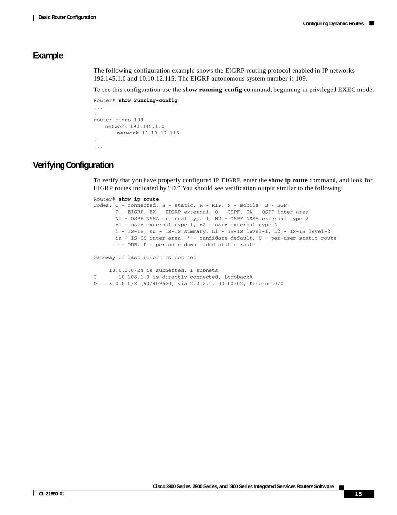
Example
The following configuration example shows the EIGRP routing protocol enabled in IP networks 192.145.1.0 and 10.10.12.115. The EIGRP autonomous system number is 109.
To see this configuration use the show running-config command, beginning in privileged EXEC mode.
Router# show running-config...!router eigrp 109
network 192.145.1.0network 10.10.12.115
!...
Verifying Configuration
To verify that you have properly configured IP EIGRP, enter the show ip route command, and look for EIGRP routes indicated by “D.” You should see verification output similar to the following:
Router# show ip routeCodes: C - connected, S - static, R - RIP, M - mobile, B - BGP D - EIGRP, EX - EIGRP external, O - OSPF, IA - OSPF inter area N1 - OSPF NSSA external type 1, N2 - OSPF NSSA external type 2 E1 - OSPF external type 1, E2 - OSPF external type 2 i - IS-IS, su - IS-IS summary, L1 - IS-IS level-1, L2 - IS-IS level-2 ia - IS-IS inter area, * - candidate default, U - per-user static route o - ODR, P - periodic downloaded static route
Gateway of last resort is not set
10.0.0.0/24 is subnetted, 1 subnetsC 10.108.1.0 is directly connected, Loopback0D 3.0.0.0/8 [90/409600] via 2.2.2.1, 00:00:02, Ethernet0/0
15Cisco 3900 Series, 2900 Series, and 1900 Series Integrated Services Routers Software
OL-21850-01
Basic Router Configuration Configuring Dynamic Routes
CCDE, CCENT, CCSI, Cisco Eos, Cisco HealthPresence, Cisco IronPort, the Cisco logo, Cisco Nurse Connect, Cisco Pulse, Cisco SensorBase, Cisco StackPower, Cisco StadiumVision, Cisco TelePresence, Cisco Unified Computing System, Cisco WebEx, DCE, Flip Channels, Flip for Good, Flip Mino, Flipshare (Design), Flip Ultra, Flip Video, Flip Video (Design), Instant Broadband, and Welcome to the Human Network are trademarks; Changing the Way We Work, Live, Play, and Learn, Cisco Capital, Cisco Capital (Design), Cisco:Financed (Stylized), Cisco Store, Flip Gift Card, and One Million Acts of Green are service marks; and Access Registrar, Aironet, AllTouch, AsyncOS, Bringing the Meeting To You, Catalyst, CCDA, CCDP, CCIE, CCIP, CCNA, CCNP, CCSP, CCVP, Cisco, the Cisco Certified Internetwork Expert logo, Cisco IOS, Cisco Lumin, Cisco Nexus, Cisco Press, Cisco Systems, Cisco Systems Capital, the Cisco Systems logo, Cisco Unity, Collaboration Without Limitation, Continuum, EtherFast, EtherSwitch, Event Center, Explorer, Follow Me Browsing, GainMaker, iLYNX, IOS, iPhone, IronPort, the IronPort logo, Laser Link, LightStream, Linksys, MeetingPlace, MeetingPlace Chime Sound, MGX, Networkers, Networking Academy, PCNow, PIX, PowerKEY, PowerPanels, PowerTV, PowerTV (Design), PowerVu, Prisma, ProConnect, ROSA, SenderBase, SMARTnet, Spectrum Expert, StackWise, WebEx, and the WebEx logo are registered trademarks of Cisco Systems, Inc. and/or its affiliates in the United States and certain other countries.
All other trademarks mentioned in this document or website are the property of their respective owners. The use of the word partner does not imply a partnership relationship between Cisco and any other company. (0910R)
Any Internet Protocol (IP) addresses used in this document are not intended to be actual addresses. Any examples, command display output, and figures included in the document are shown for illustrative purposes only. Any use of actual IP addresses in illustrative content is unintentional and coincidental. © 2009-2010 Cisco Systems, Inc. All rights reserved.
16Cisco 3900 Series, 2900 Series, and 1900 Series Integrated Services Routers Software
Configuring Backup Data Lines and Remote Management
Cisco 3900 series, 2900 series, and 1900 series integrated services routers (ISRs) support remote management and backup data connectivity by means of ISDN.
The following sections describe how to configure backup data lines and remote management:
• Configuring Backup Interfaces, page 1
• Configuring Dial Backup and Remote Management Through the Console Port or Auxiliary Port, page 13
• Configuring Data Line Backup and Remote Management Through the ISDN S/T Port, page 20
Configuring Backup InterfacesThis section contains the following topics:
• Configuring the Backup Interface, page 1
• Configuring Gigabit Ethernet Failover Media, page 3
• Configuring Cellular Dial-on-Demand Routing Backup, page 5
Configuring the Backup InterfaceWhen the router receives an indication that the primary interface is down, the backup interface is enabled. After the primary connection is restored for a specified period, the backup interface is disabled.
Note For dial-on-demand routing (DDR) backup, even if the backup interface comes out of standby mode, the router does not enable the backup interface unless the router receives the traffic specified for that backup interface.
To configure the router with a backup interface, follow these steps, beginning in global configuration mode.
Americas Headquarters:Cisco Systems, Inc., 170 West Tasman Drive, San Jose, CA 95134-1706 USA

Configuring Backup Data Lines and Remote Management Configuring Backup Interfaces
SUMMARY STEPS
1. interface type number
2. backup interface interface-type interface-number
3. backup delay enable-delay disable-delay
4. exit
DETAILED STEPS
Command Purpose
Step 1 interface type number
Example:Router(config)# interface atm 0/0/0Router(config-if)#
Enters interface configuration mode for the interface for which you want to configure backup.
The example shows configuration of a backup interface for an ATM WAN connection.
Step 2 backup interface interface-type interface-number
Example:Router(config-if)# backup interface bri 0/0/1Router(config-if)#
Assigns an interface as the secondary or backup interface.
This can be a serial interface or an asynchronous interface. For example, a serial 1 interface could be configured to back up a serial 0/2/1 interface.
The example shows a BRI interface configured as the backup interface for the ATM 0/0/0 interface.
Step 3 backup delay enable-delay disable-delay
Example:Router(config-if)# backup delay enable delay
Specifies the delay between the physical interface going down and the backup interface being enabled, and the delay between the physical interface coming back up and the backup interface being disabled.
Step 4 exit
Example:Router(config-if)# exitRouter(config)#
Exits configuration interface mode.
2Cisco 3900 Series, 2900 Series, and 1900 Series Integrated Services Routers Software Configuration Guide
Configuring Backup Data Lines and Remote Management Configuring Backup Interfaces
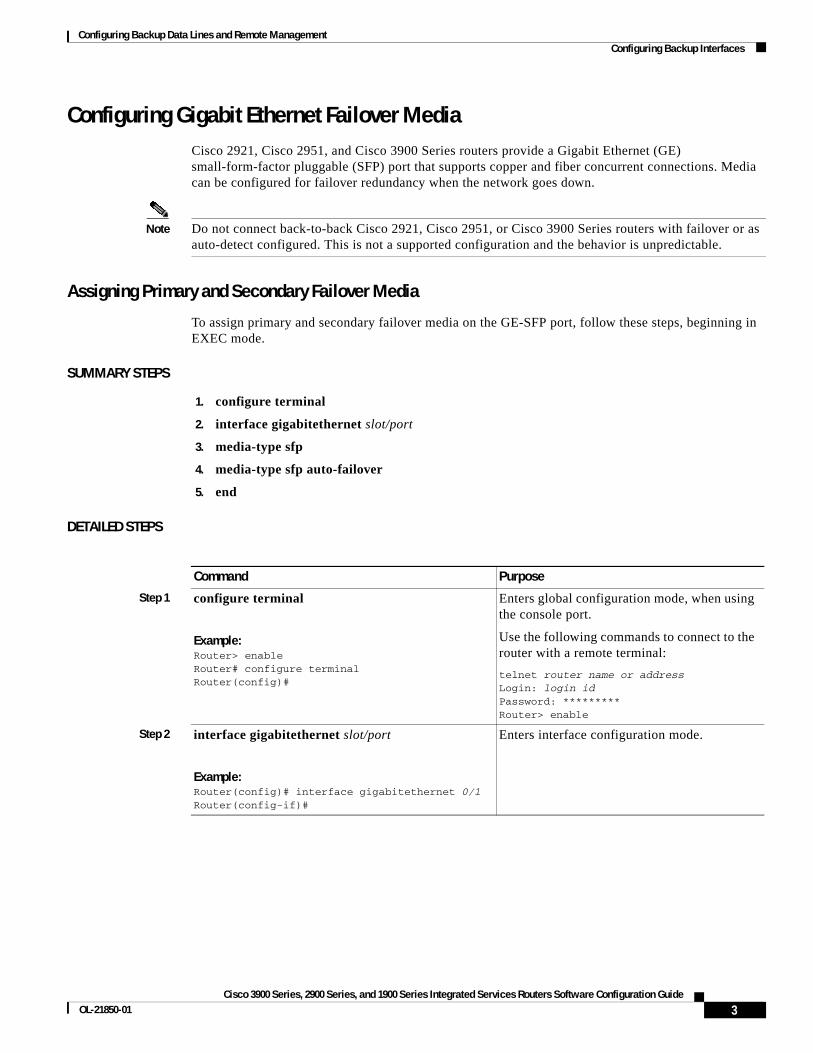
Configuring Gigabit Ethernet Failover MediaCisco 2921, Cisco 2951, and Cisco 3900 Series routers provide a Gigabit Ethernet (GE) small-form-factor pluggable (SFP) port that supports copper and fiber concurrent connections. Media can be configured for failover redundancy when the network goes down.
Note Do not connect back-to-back Cisco 2921, Cisco 2951, or Cisco 3900 Series routers with failover or as auto-detect configured. This is not a supported configuration and the behavior is unpredictable.
Assigning Primary and Secondary Failover Media
To assign primary and secondary failover media on the GE-SFP port, follow these steps, beginning in EXEC mode.
SUMMARY STEPS
1. configure terminal
2. interface gigabitethernet slot/port
3. media-type sfp
4. media-type sfp auto-failover
5. end
DETAILED STEPS
Command Purpose
Step 1 configure terminal
Example:Router> enableRouter# configure terminalRouter(config)#
Enters global configuration mode, when using the console port.
Use the following commands to connect to the router with a remote terminal:
telnet router name or addressLogin: login idPassword: *********Router> enable
Step 2 interface gigabitethernet slot/port
Example:Router(config)# interface gigabitethernet 0/1Router(config-if)#
Enters interface configuration mode.
3Cisco 3900 Series, 2900 Series, and 1900 Series Integrated Services Routers Software Configuration Guide
OL-21850-01

Configuring Backup Data Lines and Remote Management Configuring Backup Interfaces
Enabling Auto-Detect
The Auto-Detect feature is enabled if media-type is not configured. This feature automatically detects which media is connected and links up. If both media are connected, whichever media comes up first is linked up.
Note The Auto-Detect feature only works with 1 GigE SFPs. This feature does not detect 100M SFPs.
Use the no media-type command in interface configuration mode to enable the Auto-Detect feature.
To configure the Auto-Detect feature, follow these steps, beginning in global configuration mode.
SUMMARY STEPS
1. configure terminal
2. interface gigabitethernet slot/port
3. no media-type
Step 3 media-type sfp
Example:Router(config-if)# media-type sfpRouter(config-if)#
Example:Router(config-if)# media-type rj45Router(config-if)#
Designates SFP port as the primary media.
OR
Designates RJ-45 as the primary media.
Step 4 media-type sfp auto-failover
Example:Router(config-if)# media-type sfp auto-failoverRouter(config-if)#
Example:Router(config-if)# media-type rj45 auto-failoverRouter(config-if)#
Configures the port with SFP as the primary media for automatic failover from SFP to RJ-45.
OR
Configures the port with RJ-45 as the primary media for automatic failover from RJ-45 to SFP.
Step 5 end Exits to global configuration mode.
Command Purpose
4Cisco 3900 Series, 2900 Series, and 1900 Series Integrated Services Routers Software Configuration Guide
Configuring Backup Data Lines and Remote Management Configuring Backup Interfaces
DETAILED STEPS
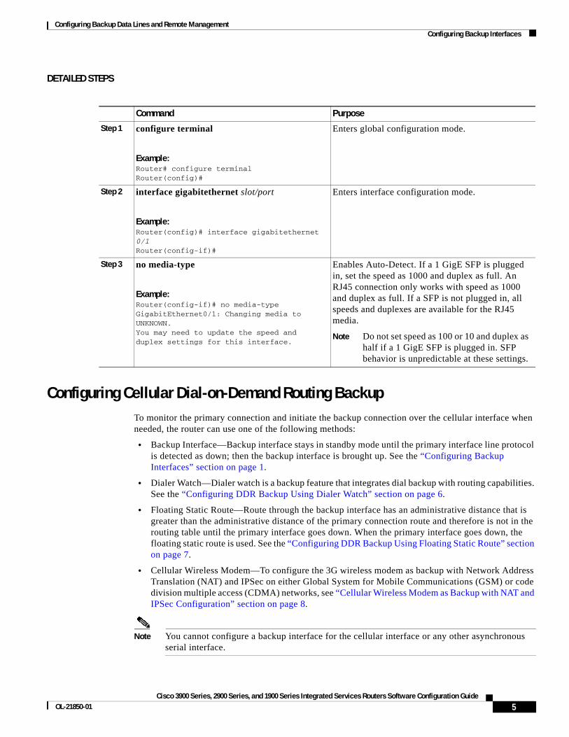
Configuring Cellular Dial-on-Demand Routing BackupTo monitor the primary connection and initiate the backup connection over the cellular interface when needed, the router can use one of the following methods:
• Backup Interface—Backup interface stays in standby mode until the primary interface line protocol is detected as down; then the backup interface is brought up. See the “Configuring Backup Interfaces” section on page 1.
• Dialer Watch—Dialer watch is a backup feature that integrates dial backup with routing capabilities. See the “Configuring DDR Backup Using Dialer Watch” section on page 6.
• Floating Static Route—Route through the backup interface has an administrative distance that is greater than the administrative distance of the primary connection route and therefore is not in the routing table until the primary interface goes down. When the primary interface goes down, the floating static route is used. See the “Configuring DDR Backup Using Floating Static Route” section on page 7.
• Cellular Wireless Modem—To configure the 3G wireless modem as backup with Network Address Translation (NAT) and IPSec on either Global System for Mobile Communications (GSM) or code division multiple access (CDMA) networks, see “Cellular Wireless Modem as Backup with NAT and IPSec Configuration” section on page 8.
Note You cannot configure a backup interface for the cellular interface or any other asynchronous serial interface.
Command Purpose
Step 1 configure terminal
Example:Router# configure terminalRouter(config)#
Enters global configuration mode.
Step 2 interface gigabitethernet slot/port
Example:Router(config)# interface gigabitethernet 0/1Router(config-if)#
Enters interface configuration mode.
Step 3 no media-type
Example:Router(config-if)# no media-typeGigabitEthernet0/1: Changing media to UNKNOWN.You may need to update the speed and duplex settings for this interface.
Enables Auto-Detect. If a 1 GigE SFP is plugged in, set the speed as 1000 and duplex as full. An RJ45 connection only works with speed as 1000 and duplex as full. If a SFP is not plugged in, all speeds and duplexes are available for the RJ45 media.
Note Do not set speed as 100 or 10 and duplex as half if a 1 GigE SFP is plugged in. SFP behavior is unpredictable at these settings.
5Cisco 3900 Series, 2900 Series, and 1900 Series Integrated Services Routers Software Configuration Guide
OL-21850-01
Configuring Backup Data Lines and Remote Management Configuring Backup Interfaces
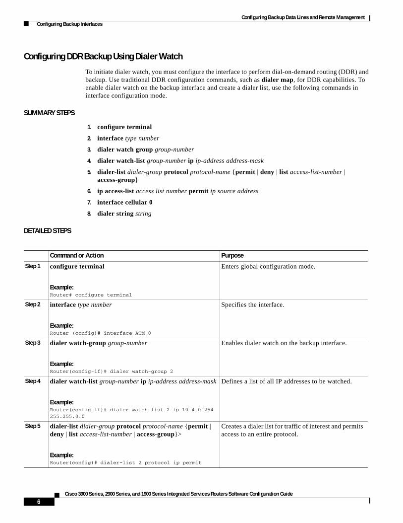
Configuring DDR Backup Using Dialer Watch
To initiate dialer watch, you must configure the interface to perform dial-on-demand routing (DDR) and backup. Use traditional DDR configuration commands, such as dialer map, for DDR capabilities. To enable dialer watch on the backup interface and create a dialer list, use the following commands in interface configuration mode.
SUMMARY STEPS
1. configure terminal
2. interface type number
3. dialer watch group group-number
4. dialer watch-list group-number ip ip-address address-mask
5. dialer-list dialer-group protocol protocol-name {permit | deny | list access-list-number | access-group}
6. ip access-list access list number permit ip source address
7. interface cellular 0
8. dialer string string
DETAILED STEPS
Command or Action Purpose
Step 1 configure terminal
Example:Router# configure terminal
Enters global configuration mode.
Step 2 interface type number
Example:Router (config)# interface ATM 0
Specifies the interface.
Step 3 dialer watch-group group-number
Example:Router(config-if)# dialer watch-group 2
Enables dialer watch on the backup interface.
Step 4 dialer watch-list group-number ip ip-address address-mask
Example:Router(config-if)# dialer watch-list 2 ip 10.4.0.254 255.255.0.0
Defines a list of all IP addresses to be watched.
Step 5 dialer-list dialer-group protocol protocol-name {permit | deny | list access-list-number | access-group}>
Example:Router(config)# dialer-list 2 protocol ip permit
Creates a dialer list for traffic of interest and permits access to an entire protocol.
6Cisco 3900 Series, 2900 Series, and 1900 Series Integrated Services Routers Software Configuration Guide

Configuring Backup Data Lines and Remote Management Configuring Backup Interfaces
Configuring DDR Backup Using Floating Static Route
To configure a floating static default route on the secondary interface, use the following commands, beginning in global configuration mode.
Note Make sure you have IP classless enabled on your router.
SUMMARY STEPS
1. configure terminal
2. ip route network-number network-mask {ip address | interface} [administrative-distance] [name name]
Step 6 ip access-list access-list-number permit ip-source-address
Example:Router(config)# access list 2 permit 10.4.0.0
Defines traffic of interest.
Do not use the access list permit all command to avoid sending traffic to the IP network. This may result in call termination.
Step 7 interface cellular 0
Example:Router (config)# interface cellular 0
Specifies the cellular interface.
Step 8 dialer string string
or
dialer group dialer-group-number
Example:Router (config-if)# dialer string cdma *** cdma ***
Example:Router (config-if)# dialer group 2 *** gsm ***
CDMA only—dialer string string specifies the dialer script. (The dialer script is defined by using the chat script command).
GSM only—dialer group dialer-group-number maps a dialer list to the dialer interface.
Command or Action Purpose
7Cisco 3900 Series, 2900 Series, and 1900 Series Integrated Services Routers Software Configuration Guide
OL-21850-01

Configuring Backup Data Lines and Remote Management Configuring Backup Interfaces
DETAILED STEPS
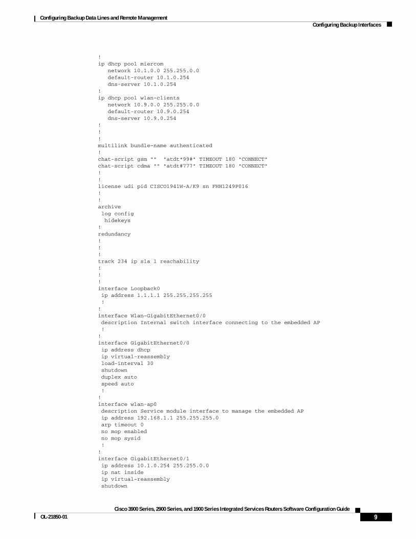
Cellular Wireless Modem as Backup with NAT and IPSec Configuration
The following example shows how to configure the 3G wireless modem as backup with NAT and IPsec on either GSM or CDMA networks.
Note The receive and transmit speeds cannot be configured. The actual throughput depends on the cellular network service.
Router# sh runBuilding configuration...
Current configuration : 5833 bytes!! Last configuration change at 18:26:15 UTC Wed Sep 30 2009!version 12.4service timestamps debug datetime msecservice timestamps log datetime msecno service password-encryptionservice internal!hostname Router!boot-start-markerboot-end-marker!!no aaa new-model!!!service-module wlan-ap 0 bootimage autonomous!no ipv6 cefip source-routeip cef!!ip multicast-routing
Command or Action Purpose
Step 1 configure terminal
Example:Router# configure terminal
Enters global configuration mode from the terminal.
Step 2 ip route network-number network-mask {ip-address | interface} [administrative-distance] [name name]
Example:Router (config)# ip route 0.0.0.0 Dialer 2 track 234
Establishes a floating static route with the configured administrative distance through the specified interface.
A higher administrative distance should be configured for the route through the backup interface, so that the backup interface is used only when the primary interface is down.
8Cisco 3900 Series, 2900 Series, and 1900 Series Integrated Services Routers Software Configuration Guide
Configuring Backup Data Lines and Remote Management Configuring Backup Interfaces
!ip dhcp pool miercom network 10.1.0.0 255.255.0.0 default-router 10.1.0.254 dns-server 10.1.0.254 !ip dhcp pool wlan-clients network 10.9.0.0 255.255.0.0 default-router 10.9.0.254 dns-server 10.9.0.254 !!!multilink bundle-name authenticated!chat-script gsm "" "atdt*99#" TIMEOUT 180 "CONNECT"chat-script cdma "" "atdt#777" TIMEOUT 180 "CONNECT"!!license udi pid CISCO1941W-A/K9 sn FHH1249P016!!archive log config hidekeys!redundancy!!!track 234 ip sla 1 reachability! !!interface Loopback0 ip address 1.1.1.1 255.255.255.255 !!interface Wlan-GigabitEthernet0/0 description Internal switch interface connecting to the embedded AP !!interface GigabitEthernet0/0 ip address dhcp ip virtual-reassembly load-interval 30 shutdown duplex auto speed auto !!interface wlan-ap0 description Service module interface to manage the embedded AP ip address 192.168.1.1 255.255.255.0 arp timeout 0 no mop enabled no mop sysid !!interface GigabitEthernet0/1 ip address 10.1.0.254 255.255.0.0 ip nat inside ip virtual-reassembly shutdown
9Cisco 3900 Series, 2900 Series, and 1900 Series Integrated Services Routers Software Configuration Guide
OL-21850-01

Configuring Backup Data Lines and Remote Management Configuring Backup Interfaces
duplex auto speed auto crypto ipsec client ezvpn hw-client-pri inside crypto ipsec client ezvpn hw-client inside !!interface Cellular0/0/0 no ip address ip access-group 131 out ip nat outside ip virtual-reassembly encapsulation ppp load-interval 30 dialer in-band dialer pool-member 1 dialer idle-timeout 0 dialer-group 1 no peer default ip address async mode interactive no ppp lcp fast-start ppp ipcp dns request ppp timeout retry 120 ppp timeout ncp 30 fair-queue 64 16 0 ! routing dynamic!interface ATM0/1/0 no ip address no atm ilmi-keepalive no dsl bitswap !!interface ATM0/1/0.1 point-to-point ip virtual-reassembly pvc 0/35 pppoe-client dial-pool-number 2 !!interface Vlan1 ip address 10.9.0.254 255.255.0.0 ip nat inside ip virtual-reassembly !!interface Dialer1 ip address negotiated ip access-group 131 out ip nat outside ip virtual-reassembly encapsulation ppp load-interval 30 dialer pool 1 dialer idle-timeout 0 dialer string cdma dialer persistent dialer-group 1 no peer default ip address no ppp lcp fast-start ppp chap hostname nousername ppp chap password 0 nopassword ppp ipcp dns request ppp timeout retry 120 ppp timeout ncp 30
10Cisco 3900 Series, 2900 Series, and 1900 Series Integrated Services Routers Software Configuration Guide

Configuring Backup Data Lines and Remote Management Configuring Backup Interfaces
fair-queue crypto ipsec client ezvpn hw-client !!interface Dialer2 ip address negotiated ip mtu 1492 ip nat outside ip virtual-reassembly encapsulation ppp load-interval 30 dialer pool 2 dialer idle-timeout 0 dialer persistent dialer-group 2 ppp authentication chap callin ppp chap hostname [email protected] ppp chap password 0 Enzo221 ppp pap sent-username [email protected] password 0 Enzo221 ppp ipcp dns request no cdp enable crypto ipsec client ezvpn hw-client-pri !!ip local policy route-map track-primary-ifip forward-protocol nd!no ip http serverno ip http secure-server!ip dns serverip nat inside source route-map nat2cell interface Dialer1 overloadip nat inside source route-map nat2dsl interface Dialer2 overloadip route 0.0.0.0 0.0.0.0 Dialer2 track 234ip route 0.0.0.0 0.0.0.0 Dialer1 253! ip sla 1 icmp-echo 128.107.248.247 source-interface Dialer2 frequency 5ip sla schedule 1 life forever start-time nowaccess-list 1 permit anyaccess-list 2 permit 10.1.0.0 0.0.255.255access-list 100 deny ip 10.1.0.0 0.0.0.255 10.4.0.0 0.0.0.255access-list 100 permit ip any anyaccess-list 101 permit ip 10.0.0.0 0.255.255.255 anyaccess-list 101 permit ip host 1.1.1.1 anyaccess-list 102 permit icmp any host 128.107.248.247access-list 131 deny ip 10.0.0.0 0.255.255.255 any log-inputaccess-list 131 permit ip any anydialer-list 1 protocol ip permitdialer-list 2 protocol ip permit!no cdp run
!!!route-map track-primary-if permit 10 match ip address 102 set interface Dialer2 Null0!route-map nat2dsl permit 10 match ip address 101 match interface Dialer2
11Cisco 3900 Series, 2900 Series, and 1900 Series Integrated Services Routers Software Configuration Guide
OL-21850-01

Configuring Backup Data Lines and Remote Management Configuring Backup Interfaces
!route-map nat2cell permit 10 match ip address 101 match interface Dialer1!!!control-plane !!!line con 0 exec-timeout 0 0line aux 0line 0/0/0 exec-timeout 0 0 script dialer cdma login modem InOut no exec transport input all transport output all autoselect ppp rxspeed 3100000 txspeed 1800000line 67 no activation-character no exec transport preferred none transport input all transport output pad telnet rlogin lapb-ta mop udptn v120 sshline vty 0 4 login!exception data-corruption buffer truncatescheduler allocate 20000 1000event manager applet pri_back event track 234 state any action 2.0 cli command "clear ip nat trans forced"!end
Router#
12Cisco 3900 Series, 2900 Series, and 1900 Series Integrated Services Routers Software Configuration Guide

Configuring Backup Data Lines and Remote Management Configuring Dial Backup and Remote Management Through the Console Port or Auxiliary Port
Configuring Dial Backup and Remote Management Through the Console Port or Auxiliary Port
When customer premises equipment, such as a Cisco 3900 series ISR, is connected to an ISP, an IP address is dynamically assigned to the router, or the IP address is assigned by the router peer through the centrally managed function. The dial backup feature can be added to provide a failover route in case the primary line fails. Cisco 3900 series ISRs can use the auxiliary port for dial backup and remote management.
Figure 1 shows the network configuration used for remote management access and for providing backup to the primary WAN line.
Figure 1 Dial Backup and Remote Management Through the Auxiliary Port
1 Cisco 3900 series router
A Main WAN link; primary connection to Internet service provider
2 Modem B Dial backup; serves as a failover link for Cisco 3900 routers when primary line goes down
3 PC C Remote management; serves as dial-in access to allow changes or updates to Cisco IOS configurations
8226
9
A1
3
2
2
C
B
BC
2
ATM
PSTN
13Cisco 3900 Series, 2900 Series, and 1900 Series Integrated Services Routers Software Configuration Guide
OL-21850-01
Configuring Backup Data Lines and Remote Management Configuring Dial Backup and Remote Management Through the Console Port or Auxiliary Port
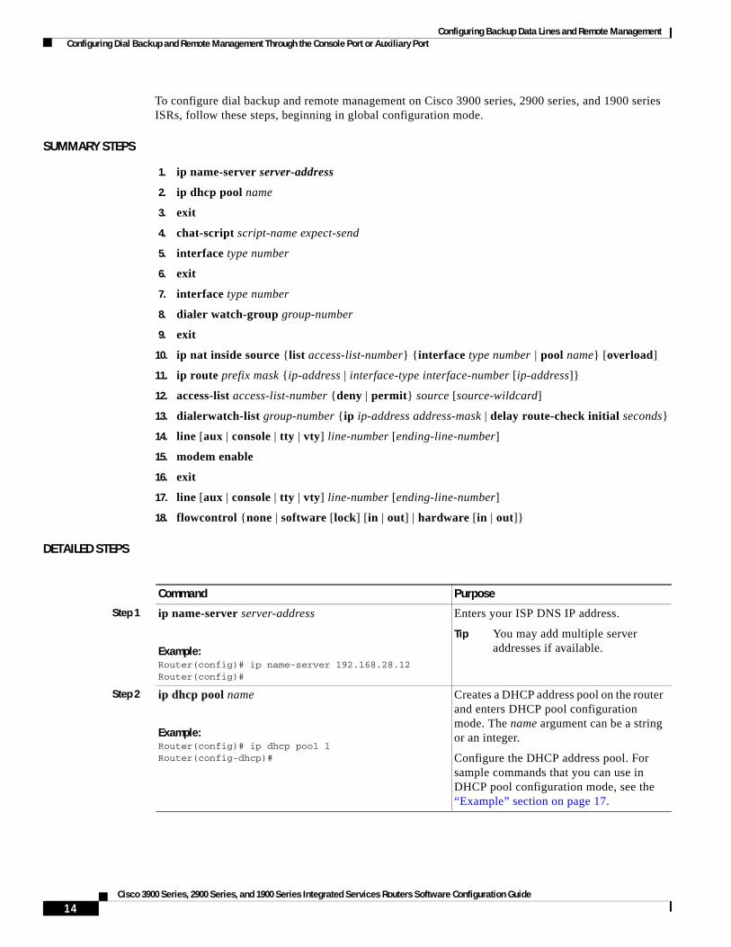
To configure dial backup and remote management on Cisco 3900 series, 2900 series, and 1900 series ISRs, follow these steps, beginning in global configuration mode.
SUMMARY STEPS
1. ip name-server server-address
2. ip dhcp pool name
3. exit
4. chat-script script-name expect-send
5. interface type number
6. exit
7. interface type number
8. dialer watch-group group-number
9. exit
10. ip nat inside source {list access-list-number} {interface type number | pool name} [overload]
11. ip route prefix mask {ip-address | interface-type interface-number [ip-address]}
12. access-list access-list-number {deny | permit} source [source-wildcard]
13. dialerwatch-list group-number {ip ip-address address-mask | delay route-check initial seconds}
14. line [aux | console | tty | vty] line-number [ending-line-number]
15. modem enable
16. exit
17. line [aux | console | tty | vty] line-number [ending-line-number]
18. flowcontrol {none | software [lock] [in | out] | hardware [in | out]}
DETAILED STEPS
Command Purpose
Step 1 ip name-server server-address
Example:Router(config)# ip name-server 192.168.28.12Router(config)#
Enters your ISP DNS IP address.
Tip You may add multiple server addresses if available.
Step 2 ip dhcp pool name
Example:Router(config)# ip dhcp pool 1Router(config-dhcp)#
Creates a DHCP address pool on the router and enters DHCP pool configuration mode. The name argument can be a string or an integer.
Configure the DHCP address pool. For sample commands that you can use in DHCP pool configuration mode, see the “Example” section on page 17.
14Cisco 3900 Series, 2900 Series, and 1900 Series Integrated Services Routers Software Configuration Guide
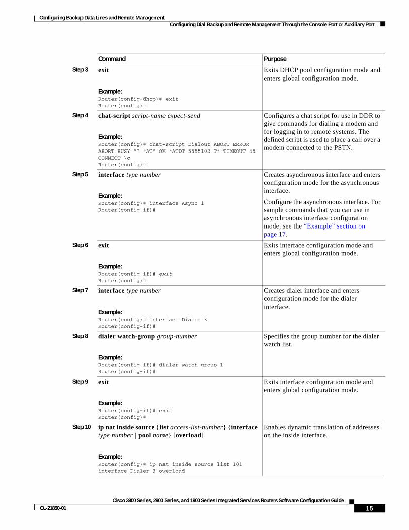
Configuring Backup Data Lines and Remote Management Configuring Dial Backup and Remote Management Through the Console Port or Auxiliary Port
Step 3 exit
Example:Router(config-dhcp)# exitRouter(config)#
Exits DHCP pool configuration mode and enters global configuration mode.
Step 4 chat-script script-name expect-send
Example:Router(config)# chat-script Dialout ABORT ERROR ABORT BUSY ““ “AT” OK “ATDT 5555102 T” TIMEOUT 45 CONNECT \cRouter(config)#
Configures a chat script for use in DDR to give commands for dialing a modem and for logging in to remote systems. The defined script is used to place a call over a modem connected to the PSTN.
Step 5 interface type number
Example:Router(config)# interface Async 1Router(config-if)#
Creates asynchronous interface and enters configuration mode for the asynchronous interface.
Configure the asynchronous interface. For sample commands that you can use in asynchronous interface configuration mode, see the “Example” section on page 17.
Step 6 exit
Example:Router(config-if)# exitRouter(config)#
Exits interface configuration mode and enters global configuration mode.
Step 7 interface type number
Example:Router(config)# interface Dialer 3Router(config-if)#
Creates dialer interface and enters configuration mode for the dialer interface.
Step 8 dialer watch-group group-number
Example:Router(config-if)# dialer watch-group 1Router(config-if)#
Specifies the group number for the dialer watch list.
Step 9 exit
Example:Router(config-if)# exitRouter(config)#
Exits interface configuration mode and enters global configuration mode.
Step 10 ip nat inside source {list access-list-number} {interface type number | pool name} [overload]
Example:Router(config)# ip nat inside source list 101 interface Dialer 3 overload
Enables dynamic translation of addresses on the inside interface.
Command Purpose
15Cisco 3900 Series, 2900 Series, and 1900 Series Integrated Services Routers Software Configuration Guide
OL-21850-01

Configuring Backup Data Lines and Remote Management Configuring Dial Backup and Remote Management Through the Console Port or Auxiliary Port
Step 11 ip route prefix mask {ip-address | interface-type interface-number [ip-address]}
Example:Router(config)# ip route 0.0.0.0 0.0.0.0 22.0.0.2Router(config)#
Sets the IP route to point to the dialer interface as a default gateway.
Step 12 access-list access-list-number {deny | permit} source [source-wildcard]
Example:Router(config)# access-list 1 permit 192.168.0.0 0.0.255.255 any
Defines an extended access list that indicates which addresses need translation.
Step 13 dialerwatch-list group-number {ip ip-address address-mask | delay route-check initial seconds}
Example:Router(config)# dialer watch-list 1 ip 22.0.0.2 255.255.255.255Router(config)#
Evaluates the status of the primary link, based on the existence of routes to the peer. The address 22.0.0.2 is the peer IP address of the ISP.
Step 14 line [aux | console | tty | vty] line-number [ending-line-number]
Example:Router(config)# line console 0Router(config-line)#
Enters configuration mode for the line interface.
Step 15 modem enable
Example:Router(config-line)# modem enableRouter(config-line)#
Switches the port from console port to auxiliary port function.
Step 16 exit
Example:Router(config-line)# exitRouter(config)#
Exits interface configuration mode.
Command Purpose
16Cisco 3900 Series, 2900 Series, and 1900 Series Integrated Services Routers Software Configuration Guide
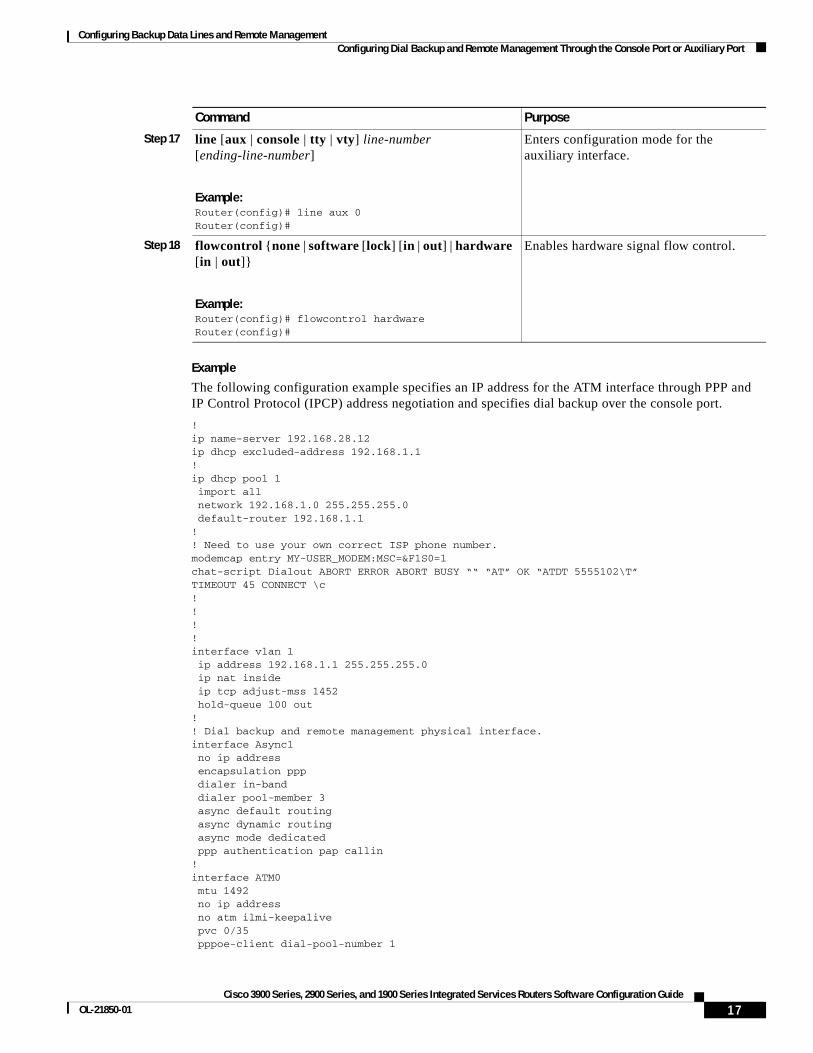
Configuring Backup Data Lines and Remote Management Configuring Dial Backup and Remote Management Through the Console Port or Auxiliary Port
Example
The following configuration example specifies an IP address for the ATM interface through PPP and IP Control Protocol (IPCP) address negotiation and specifies dial backup over the console port.
!ip name-server 192.168.28.12ip dhcp excluded-address 192.168.1.1!ip dhcp pool 1 import all network 192.168.1.0 255.255.255.0 default-router 192.168.1.1!! Need to use your own correct ISP phone number.modemcap entry MY-USER_MODEM:MSC=&F1S0=1chat-script Dialout ABORT ERROR ABORT BUSY ““ “AT” OK “ATDT 5555102\T”TIMEOUT 45 CONNECT \c!!!!interface vlan 1 ip address 192.168.1.1 255.255.255.0 ip nat inside ip tcp adjust-mss 1452 hold-queue 100 out!! Dial backup and remote management physical interface.interface Async1 no ip address encapsulation ppp dialer in-band dialer pool-member 3 async default routing async dynamic routing async mode dedicated ppp authentication pap callin!interface ATM0 mtu 1492 no ip address no atm ilmi-keepalive pvc 0/35 pppoe-client dial-pool-number 1
Step 17 line [aux | console | tty | vty] line-number [ending-line-number]
Example:Router(config)# line aux 0Router(config)#
Enters configuration mode for the auxiliary interface.
Step 18 flowcontrol {none | software [lock] [in | out] | hardware [in | out]}
Example:Router(config)# flowcontrol hardwareRouter(config)#
Enables hardware signal flow control.
Command Purpose
17Cisco 3900 Series, 2900 Series, and 1900 Series Integrated Services Routers Software Configuration Guide
OL-21850-01
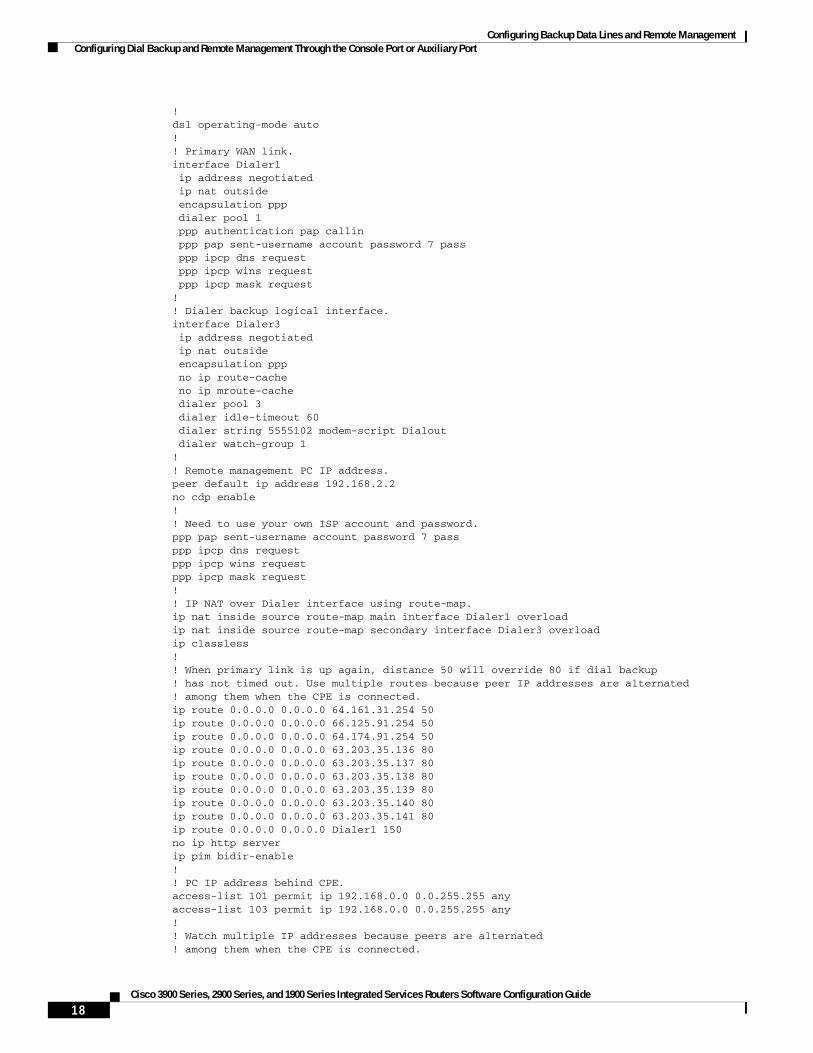
Configuring Backup Data Lines and Remote Management Configuring Dial Backup and Remote Management Through the Console Port or Auxiliary Port
!dsl operating-mode auto!! Primary WAN link.interface Dialer1 ip address negotiated ip nat outside encapsulation ppp dialer pool 1 ppp authentication pap callin ppp pap sent-username account password 7 pass ppp ipcp dns request ppp ipcp wins request ppp ipcp mask request!! Dialer backup logical interface.interface Dialer3 ip address negotiated ip nat outside encapsulation ppp no ip route-cache no ip mroute-cache dialer pool 3 dialer idle-timeout 60 dialer string 5555102 modem-script Dialout dialer watch-group 1!! Remote management PC IP address.peer default ip address 192.168.2.2no cdp enable!! Need to use your own ISP account and password.ppp pap sent-username account password 7 passppp ipcp dns requestppp ipcp wins requestppp ipcp mask request!! IP NAT over Dialer interface using route-map.ip nat inside source route-map main interface Dialer1 overloadip nat inside source route-map secondary interface Dialer3 overloadip classless!! When primary link is up again, distance 50 will override 80 if dial backup ! has not timed out. Use multiple routes because peer IP addresses are alternated ! among them when the CPE is connected.ip route 0.0.0.0 0.0.0.0 64.161.31.254 50ip route 0.0.0.0 0.0.0.0 66.125.91.254 50ip route 0.0.0.0 0.0.0.0 64.174.91.254 50ip route 0.0.0.0 0.0.0.0 63.203.35.136 80ip route 0.0.0.0 0.0.0.0 63.203.35.137 80ip route 0.0.0.0 0.0.0.0 63.203.35.138 80ip route 0.0.0.0 0.0.0.0 63.203.35.139 80ip route 0.0.0.0 0.0.0.0 63.203.35.140 80ip route 0.0.0.0 0.0.0.0 63.203.35.141 80ip route 0.0.0.0 0.0.0.0 Dialer1 150no ip http serverip pim bidir-enable!! PC IP address behind CPE.access-list 101 permit ip 192.168.0.0 0.0.255.255 anyaccess-list 103 permit ip 192.168.0.0 0.0.255.255 any!! Watch multiple IP addresses because peers are alternated ! among them when the CPE is connected.
18Cisco 3900 Series, 2900 Series, and 1900 Series Integrated Services Routers Software Configuration Guide
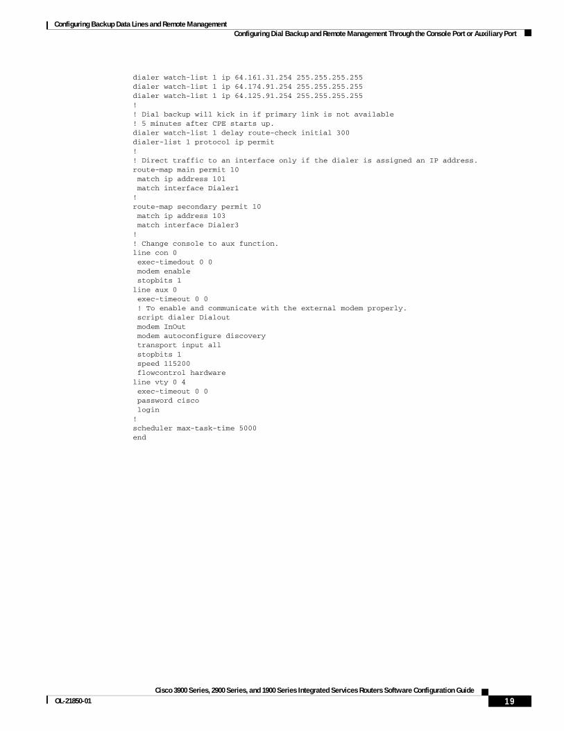
Configuring Backup Data Lines and Remote Management Configuring Dial Backup and Remote Management Through the Console Port or Auxiliary Port
dialer watch-list 1 ip 64.161.31.254 255.255.255.255dialer watch-list 1 ip 64.174.91.254 255.255.255.255dialer watch-list 1 ip 64.125.91.254 255.255.255.255!! Dial backup will kick in if primary link is not available ! 5 minutes after CPE starts up.dialer watch-list 1 delay route-check initial 300dialer-list 1 protocol ip permit!! Direct traffic to an interface only if the dialer is assigned an IP address.route-map main permit 10 match ip address 101 match interface Dialer1!route-map secondary permit 10 match ip address 103 match interface Dialer3!! Change console to aux function.line con 0 exec-timedout 0 0 modem enable stopbits 1line aux 0 exec-timeout 0 0 ! To enable and communicate with the external modem properly. script dialer Dialout modem InOut modem autoconfigure discovery transport input all stopbits 1 speed 115200 flowcontrol hardwareline vty 0 4 exec-timeout 0 0 password cisco login!scheduler max-task-time 5000end
19Cisco 3900 Series, 2900 Series, and 1900 Series Integrated Services Routers Software Configuration Guide
OL-21850-01

Configuring Backup Data Lines and Remote Management Configuring Data Line Backup and Remote Management Through the ISDN S/T Port
Configuring Data Line Backup and Remote Management Through the ISDN S/T Port
This section contains the following topics:
• Configuring ISDN Settings, page 21
• Example, page 24
Cisco 3900 series routers can use the ISDN S/T port for remote management. Figure 2 and Figure 3 show two typical network configurations that provide remote management access and backup for the primary WAN line.
Figure 2 shows a dial backup link that goes through a customer premises equipment (CPE) splitter, a digital subscriber line access multiplexer (DSLAM), and a central office (CO) splitter before connecting to the ISDN switch.
Figure 2 Data Line Backup Through CPE Splitter, DSLAM, and CO Splitter
1 Cisco 3900 series router A Primary DSL interface, FE interface (Cisco 3900 series router)
2 DSLAM B Dial backup and remote management through the ISDN interface (ISDN S/T port); serves as a failover link when the primary line goes down
3 ATM aggregator
4 ISDN switch
5 ISDN C Provides administrator with remote management capability through the ISDN interface when the primary DSL link is down; serves as dial-in access to allow changes or updates to Cisco IOS configuration
6 ISDN peer router
7 Web server
8 Administrator
8289
2
ATMnetwork
Internet
B
2 3
4
87
65
C
A
1
20Cisco 3900 Series, 2900 Series, and 1900 Series Integrated Services Routers Software Configuration Guide

Configuring Backup Data Lines and Remote Management Configuring Data Line Backup and Remote Management Through the ISDN S/T Port
Figure 3 shows a dial backup link that goes directly from the router to the ISDN switch.
Figure 3 Data Line Backup Directly from Router to ISDN Switch
Configuring ISDN Settings
Note Traffic of interest must be present in order to activate the backup ISDN line by means of the backup interface and floating static routes methods. Traffic of interest is not needed in order for the dialer watch to activate the backup ISDN line.
To configure your router ISDN interface for use as a backup interface, follow these steps, beginning in global configuration mode.
SUMMARY STEPS
1. isdn switch-type switch-type
2. interface type number
3. encapsulation encapsulation-type
4. dialer pool-member number
5. isdn switch-type switch-type
6. exit
1 PC A Primary DSL interface
2 Cisco 3900 series ISR B Dial backup and remote management through the ISDN interface (ISDN S/T port); serves as a failover link when the primary line goes down
3 DSLAM
4 Aggregator
5 ISDN switch C Provides administrator with remote management capability through the ISDN interface when the primary DSL link is down; serves as dial-in access to allow changes or updates to Cisco IOS configuration
6 Web server
7 Administrator
8820
8
ATMnetwork
Internet
B
5
4
3
76
C
A
12
21Cisco 3900 Series, 2900 Series, and 1900 Series Integrated Services Routers Software Configuration Guide
OL-21850-01

Configuring Backup Data Lines and Remote Management Configuring Data Line Backup and Remote Management Through the ISDN S/T Port
7. interface dialer dialer-rotary-group-number
8. ip address negotiated
9. encapsulation encapsulation-type
10. dialer pool number
11. dialer string dial-string# [:isdn-subaddress]
12. dialer-group group-number
13. exit
14. dialer-list dialer-group protocol protocol-name {permit | deny | list access-list-number | access-group}
DETAILED STEPS
Command Purpose
Step 1 isdn switch-type switch-type
Example:Router(config)# isdn switch-type basic-net3Router(config)#
Specifies the ISDN switch type.
The example specifies a switch type used in Australia, Europe, and the United Kingdom. For details on other supported switch types, see Cisco IOS Dial Technologies Command Reference.
Step 2 interface type number
Example:Router(config)# interface bri 0Router(config-if)#
Enters configuration mode for the ISDN BRI.
Step 3 encapsulation encapsulation-type
Example:Router(config-if)# encapsulation pppRouter(config-if)#
Sets the BRI0 interface encapsulation type.
Step 4 dialer pool-member number
Example:Router(config-if)# dialer pool-member 1Router(config-if)#
Specifies the dialer pool membership.
Step 5 isdn switch-type switch-type
Example:Router(config-if)# isdn switch-type basic-net3Router(config-if)#
Specifies the ISDN switch type.
Step 6 exit
Example:Router(config-if)# exitRouter(config)#
Exits interface configuration mode and enters global configuration mode.
22Cisco 3900 Series, 2900 Series, and 1900 Series Integrated Services Routers Software Configuration Guide

Configuring Backup Data Lines and Remote Management Configuring Data Line Backup and Remote Management Through the ISDN S/T Port
Step 7 interface dialer dialer-rotary-group-number
Example:Router(config)# interface dialer 0Router(config-if)#
Creates a dialer interface (numbered 0 to 255) and enters interface configuration mode.
Step 8 ip address negotiated
Example:Router(config-if)# ip address negotiatedRouter(config-if)#
Specifies that the IP address for the interface is obtained through PPP/IPCP (IP Control Protocol) address negotiation. The IP address is obtained from the peer.
Step 9 encapsulation encapsulation-type
Example:Router(config-if)# encapsulation pppRouter(config-if)#
Sets the encapsulation type for the interface.
Step 10 dialer pool number
Example:Router(config-if)# dialer pool 1Router(config-if)#
Specifies the dialer pool to be used.
In the example, the dialer pool 1 setting associates the dialer 0 interface with the BRI0 interface because the BRI0 dialer pool-member value is 1.
Step 11 dialer string dial-string# [:isdn-subaddress]
Example:Router(config-if)# dialer string 384040Router(config-if)#
Specifies the telephone number to be dialed.
Step 12 dialer-group group-number
Example:Router(config-if)# dialer group 1Router(config-if)#
Assigns the dialer interface to a dialer group (1–10).
Step 13 exit
Example:Router(config-if)# exitRouter(config)#
Exits dialer interface configuration mode and enters global configuration mode.
Step 14 dialer-list dialer-group protocol protocol-name {permit | deny | list access-list-number | access-group}
Example:Router(config)# dialer-list 1 protocol ip permitRouter(config)#
Creates a dialer list for packets of interest to be forwarded through the specified interface dialer group.
In the example, dialer-list 1 corresponds to dialer-group 1.
For details about this command and additional parameters that can be set, see Cisco IOS Dial Technologies Command Reference.
Command Purpose
23Cisco 3900 Series, 2900 Series, and 1900 Series Integrated Services Routers Software Configuration Guide
OL-21850-01

Configuring Backup Data Lines and Remote Management Configuring Data Line Backup and Remote Management Through the ISDN S/T Port
ExampleThe following configuration example configures an aggregated and ISDN peer router.
The aggregator is typically a concentrator router where your Cisco router Asynchronous Transfer Mode (ATM) permanent virtual connection (PVC) terminates. In the following configuration example, the aggregator is configured as a PPP over Ethernet (PPPoE) server.
The ISDN peer router is any router that has an ISDN interface and can communicate through a public ISDN network to reach your Cisco router ISDN interface. The ISDN peer router provides Internet access for your Cisco router during the ATM network downtime.
! This portion of the example configures the aggregator.vpdn enableno vpdn logging!vpdn-group 1 accept-dialin protocol pppoe virtual-template 1!interface Ethernet3 description “4700ref-1” ip address 40.1.1.1 255.255.255.0 media-type 10BaseT!interface Ethernet4 ip address 30.1.1.1 255.255.255.0 media-type 10BaseT!interface Virtual-Template1 ip address 22.0.0.2 255.255.255.0 ip mtu 1492 peer default ip address pool adsl!interface ATM0 no ip address pvc 1/40 encapsulation aal5snap protocol pppoe!no atm limi-keepalive!ip local pool adsl 22.0.0.1ip classlessip route 0.0.0.0 0.0.0.0 22.0.0.1 50ip route 0.0.0.0 0.0.0.0 30.1.1.2.80
! This portion of the example configures the ISDN peer.isdn switch-type basic-net3!interface Ethernet0 ip address 30.1.1.2 255.0.0.0 !interface BRI0 description “to 836-dialbackup” no ip address encapsulation ppp dialer pool-member 1 isdn switch-type basic-net3!interface Dialer0
24Cisco 3900 Series, 2900 Series, and 1900 Series Integrated Services Routers Software Configuration Guide

Configuring Backup Data Lines and Remote Management Configuring Data Line Backup and Remote Management Through the ISDN S/T Port
ip address 192.168.2.2 255.255.255.0 encapsulation ppp dialer pool 1 dialer string 384020 dialer-group 1 peer default ip address pool isdn!ip local pool isdn 192.168.2.1ip http serverip classlessip route 0.0.0.0 0.0.0.0 192.168.2.1ip route 40.0.0.0 255.0.0.0 30.1.1.1dialer-list 1 protocol ip permit
25Cisco 3900 Series, 2900 Series, and 1900 Series Integrated Services Routers Software Configuration Guide
OL-21850-01
Configuring Backup Data Lines and Remote Management Configuring Data Line Backup and Remote Management Through the ISDN S/T Port
CCDE, CCENT, CCSI, Cisco Eos, Cisco HealthPresence, Cisco IronPort, the Cisco logo, Cisco Nurse Connect, Cisco Pulse, Cisco SensorBase, Cisco StackPower, Cisco StadiumVision, Cisco TelePresence, Cisco Unified Computing System, Cisco WebEx, DCE, Flip Channels, Flip for Good, Flip Mino, Flipshare (Design), Flip Ultra, Flip Video, Flip Video (Design), Instant Broadband, and Welcome to the Human Network are trademarks; Changing the Way We Work, Live, Play, and Learn, Cisco Capital, Cisco Capital (Design), Cisco:Financed (Stylized), Cisco Store, Flip Gift Card, and One Million Acts of Green are service marks; and Access Registrar, Aironet, AllTouch, AsyncOS, Bringing the Meeting To You, Catalyst, CCDA, CCDP, CCIE, CCIP, CCNA, CCNP, CCSP, CCVP, Cisco, the Cisco Certified Internetwork Expert logo, Cisco IOS, Cisco Lumin, Cisco Nexus, Cisco Press, Cisco Systems, Cisco Systems Capital, the Cisco Systems logo, Cisco Unity, Collaboration Without Limitation, Continuum, EtherFast, EtherSwitch, Event Center, Explorer, Follow Me Browsing, GainMaker, iLYNX, IOS, iPhone, IronPort, the IronPort logo, Laser Link, LightStream, Linksys, MeetingPlace, MeetingPlace Chime Sound, MGX, Networkers, Networking Academy, PCNow, PIX, PowerKEY, PowerPanels, PowerTV, PowerTV (Design), PowerVu, Prisma, ProConnect, ROSA, SenderBase, SMARTnet, Spectrum Expert, StackWise, WebEx, and the WebEx logo are registered trademarks of Cisco Systems, Inc. and/or its affiliates in the United States and certain other countries.
All other trademarks mentioned in this document or website are the property of their respective owners. The use of the word partner does not imply a partnership relationship between Cisco and any other company. (0910R)
Any Internet Protocol (IP) addresses used in this document are not intended to be actual addresses. Any examples, command display output, and figures included in the document are shown for illustrative purposes only. Any use of actual IP addresses in illustrative content is unintentional and coincidental. © 2009-2010 Cisco Systems, Inc. All rights reserved.
26Cisco 3900 Series, 2900 Series, and 1900 Series Integrated Services Routers Software Configuration Guide

Configuring Power Efficiency Management
The Cisco 3900 series, 2900 series, and 1900 series integrated services routers generation 2 (ISR G2) have hardware and software features for reducing power consumption. The hardware features include high-efficiency AC power supplies and electrical components with built-in power saving features, such as RAM select and clock gating. See your router’s hardware installation guide for more information on these hardware features. The software features include EnergyWise, a power efficiency management feature that will power down unused modules, and disable unused clocks to the modules and peripherals on the router. ISR G2s must be running Cisco IOS Release 15.0(1)M or later to support EnergyWise. Detailed configuration procedures are included in the Cisco EnergyWise Configuration Guide, which can be found at Cisco.com.
The following sections provide general information about the EnergyWise feature running on ISR G2s:
• Modules and Interface Supporting EnergyWise, page 1
• Restrictions for Power Efficiency Management and OIR, page 2
Modules and Interface Supporting EnergyWiseTable 1 lists the modules and interface cards that are supported for use with EnergyWise at the time of this product release.
Table 1 Modules that Support the Power Efficiency Management Feature
Type of Module Module Name
SM SM-ES2-16-P
SM-SRE
NM NM-16-ESW1
NME NME-16ES-1G-P
HWIC HWIC-4ESW-POE
HWIC-1G-SFP
HWIC-2FE
ISM ISM-SRE-300-K9
Americas Headquarters:Cisco Systems, Inc., 170 West Tasman Drive, San Jose, CA 95134-1706 USA
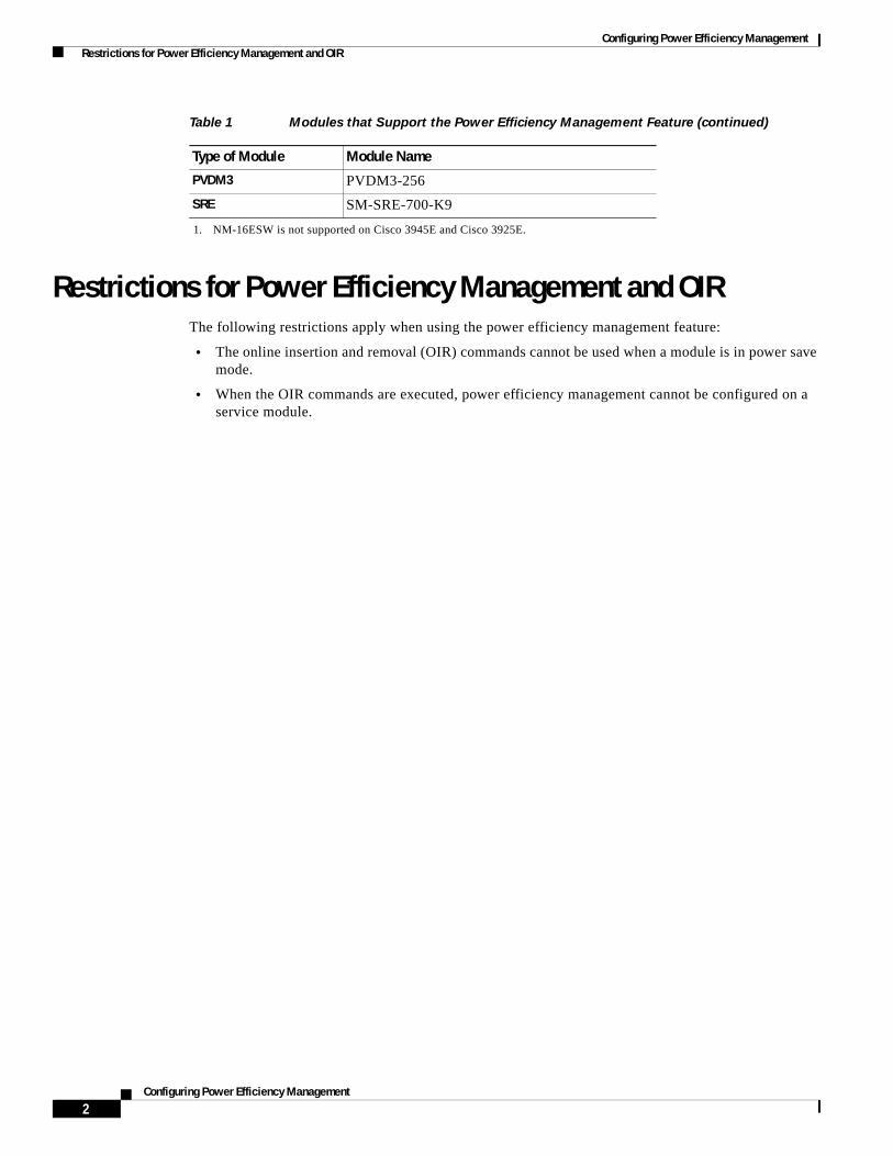
Configuring Power Efficiency Management Restrictions for Power Efficiency Management and OIR
Restrictions for Power Efficiency Management and OIRThe following restrictions apply when using the power efficiency management feature:
• The online insertion and removal (OIR) commands cannot be used when a module is in power save mode.
• When the OIR commands are executed, power efficiency management cannot be configured on a service module.
PVDM3 PVDM3-256
SRE SM-SRE-700-K9
1. NM-16ESW is not supported on Cisco 3945E and Cisco 3925E.
Table 1 Modules that Support the Power Efficiency Management Feature (continued)
Type of Module Module Name
2Configuring Power Efficiency Management

Configuring Power Efficiency Management Restrictions for Power Efficiency Management and OIR
CCDE, CCENT, CCSI, Cisco Eos, Cisco HealthPresence, Cisco IronPort, the Cisco logo, Cisco Nurse Connect, Cisco Pulse, Cisco SensorBase, Cisco StackPower, Cisco StadiumVision, Cisco TelePresence, Cisco Unified Computing System, Cisco WebEx, DCE, Flip Channels, Flip for Good, Flip Mino, Flipshare (Design), Flip Ultra, Flip Video, Flip Video (Design), Instant Broadband, and Welcome to the Human Network are trademarks; Changing the Way We Work, Live, Play, and Learn, Cisco Capital, Cisco Capital (Design), Cisco:Financed (Stylized), Cisco Store, Flip Gift Card, and One Million Acts of Green are service marks; and Access Registrar, Aironet, AllTouch, AsyncOS, Bringing the Meeting To You, Catalyst, CCDA, CCDP, CCIE, CCIP, CCNA, CCNP, CCSP, CCVP, Cisco, the Cisco Certified Internetwork Expert logo, Cisco IOS, Cisco Lumin, Cisco Nexus, Cisco Press, Cisco Systems, Cisco Systems Capital, the Cisco Systems logo, Cisco Unity, Collaboration Without Limitation, Continuum, EtherFast, EtherSwitch, Event Center, Explorer, Follow Me Browsing, GainMaker, iLYNX, IOS, iPhone, IronPort, the IronPort logo, Laser Link, LightStream, Linksys, MeetingPlace, MeetingPlace Chime Sound, MGX, Networkers, Networking Academy, PCNow, PIX, PowerKEY, PowerPanels, PowerTV, PowerTV (Design), PowerVu, Prisma, ProConnect, ROSA, SenderBase, SMARTnet, Spectrum Expert, StackWise, WebEx, and the WebEx logo are registered trademarks of Cisco Systems, Inc. and/or its affiliates in the United States and certain other countries.
All other trademarks mentioned in this document or website are the property of their respective owners. The use of the word partner does not imply a partnership relationship between Cisco and any other company. (0910R)
© 2009-2010 Cisco Systems, Inc. All rights reserved.
3Configuring Power Efficiency Management
OL-21850-01

Configuring Power Efficiency Management Restrictions for Power Efficiency Management and OIR
4Configuring Power Efficiency Management
Configuring Security Features
Cisco 3900 series, 2900 series, and 1900 series integrated services routers (ISRs) provide the following security features:
• Configuring the Cryptographic Engine Accelerator, page 1
• Configuring SSL VPN, page 2
• Authentication, Authorization, and Accounting, page 2
• Configuring AutoSecure, page 3
• Configuring Access Lists, page 3
• Configuring Cisco IOS Firewall, page 4
• Zone-Based Policy Firewall, page 5
• Configuring Cisco IOS IPS, page 5
• Content Filtering, page 5
• Configuring VPN, page 6
• Configuring Dynamic Multipoint VPN, page 23
• Configuring Group Encrypted Transport VPN, page 24
Configuring the Cryptographic Engine AcceleratorServices Performance Engine 200 and Services Performance Engine 250 have an onboard cryptographic engine accelerator that is shared between SSLVPN and IPSec protocols.
By default, acceleration of SSL is disabled so IPSec performance is maximized. To set up a router as an SSLVPN gateway, enable hardware acceleration for SSLVPN with the crypto engine accelerator bandwidth-allocation ssl fair command from global configuration mode. Issue the reload command.
Americas Headquarters:Cisco Systems, Inc., 170 West Tasman Drive, San Jose, CA 95134-1706 USA
Configuring Security Features Configuring SSL VPN
Configuring SSL VPNThe Secure Socket Layer Virtual Private Network (SSL VPN) feature (also known as WebVPN) provides support, in Cisco IOS software, for remote user access to enterprise networks from anywhere on the Internet. Remote access is provided through a SSL–enabled SSL VPN gateway. The SSL VPN gateway allows remote users to establish a secure VPN tunnel using a web browser. This feature provides a comprehensive solution that allows easy access to a broad range of web resources and web-enabled applications using native HTTP over SSL (HTTPS) browser support. SSL VPN delivers three modes of SSL VPN access: clientless, thin-client, and full-tunnel client support.
For additional information about configuring SSL VPN, see the “SSL VPN” section of Cisco IOS Security Configuration Guide: Secure Connectivity, Release 12.4T at: http://www.cisco.com/en/US/docs/ios/sec_secure_connectivity/configuration/guide/12_4t/ sec_secure_connectivity_12_4t_book.html.
Authentication, Authorization, and AccountingAuthentication, Authorization, and Accounting (AAA) network security services provide the primary framework through which you set up access control on your router. Authentication provides the method of identifying users, including login and password dialog, challenge and response, messaging support, and, depending on the security protocol you choose, encryption. Authorization provides the method for remote access control, including one-time authorization or authorization for each service, per-user account list and profile, user group support, and support of IP, Internetwork Packet Exchange (IPX), AppleTalk Remote Access (ARA), and Telnet. Accounting provides the method for collecting and sending security server information used for billing, auditing, and reporting, such as user identities, start and stop times, executed commands (such as PPP), number of packets, and number of bytes.
AAA uses protocols such as Remote Authentication Dial-In User Service (RADIUS), Terminal Access Controller Access Control System Plus (TACACS+), or Kerberos to administer its security functions. If your router is acting as a network access server, AAA is the means through which you establish communication between your network access server and your RADIUS, TACACS+, or Kerberos security server.
For information about configuring AAA services and supported security protocols, authentication authorization, accounting, RADIUS, TACACS+, or Kerberos, see the following sections of Cisco IOS Security Configuration Guide: Securing User Services, Release 12.4T at:
http://www.cisco.com/en/US/docs/ios/sec_user_services/configuration/guide/
12_4T/sec_securing_user_services_12.4t_book.html:
• Configuring Authentication
• Configuring Authorization
• Configuring Accounting
• Configuring RADIUS
• Configuring TACACS+
• Configuring Kerberos
2Cisco 3900 Series, 2900 Series, and 1900 Series Integrated Services Routers Software Configuration Guide

Configuring Security Features Configuring AutoSecure
Configuring AutoSecureThe AutoSecure feature disables common IP services that can be exploited for network attacks and enables IP services and features that can aid in the defense of a network when under attack. These IP services are all disabled and enabled simultaneously with a single command, greatly simplifying security configuration on your router. For a complete description of the AutoSecure feature, see the AutoSecure feature document at: http://www.cisco.com/univercd/cc/td/doc/product/software/ios123/123newft/123_1/ftatosec.htm.
Configuring Access ListsAccess lists permit or deny network traffic over an interface, based on source IP address, destination IP address, or protocol. Access lists are configured as standard or extended. A standard access list either permits or denies passage of packets from a designated source. An extended access list allows designation of both the destination and the source, and it allows designation of individual protocols to be permitted or denied passage.
For more complete information on creating access lists, see the “Access Control Lists” section of Cisco IOS Security Configuration Guide: Securing the Data Plane, Release 12.4T at: http://www.cisco.com/en/US/docs/ios/sec_data_plane/configuration/guide/12_4t/ sec_data_plane_12_4t_book.html.
An access list is a series of commands with a common tag to bind them together. The tag is either a number or a name. Table 1 lists the commands used to configure access lists.
To create, refine, and manage access lists, see the following sections of the “Access Control Lists” section of Cisco IOS Security Configuration Guide: Securing the Data Plane, Release 12.4T at: http://www.cisco.com/en/US/docs/ios/sec_data_plane/configuration/guide/12_4t/ sec_data_plane_12_4t_book.html:
• Creating an IP Access List and Applying It to an Interface
• Creating an IP Access List to Filter IP Options, TCP Flags, Noncontiguous Ports, or TTL Values
• Refining an IP Access List
• Displaying and Clearing IP Access List Data Using ACL Manageability
Table 1 Access List Configuration Commands
Access Control List (ACL) Type Configuration Commands
Numbered
Standard access-list {1-99}{permit | deny} source-addr [source-mask]
Extended access-list {100-199}{permit | deny} protocol source-addr [source-mask] destination-addr [destination-mask]
Named
Standard ip access-list standard name deny {source | source-wildcard | any}
Extended ip access-list extended name {permit | deny} protocol {source-addr [source-mask] | any}{destination-addr [destination-mask] | any}
3Cisco 3900 Series, 2900 Series, and 1900 Series Integrated Services Routers Software Configuration Guide
OL-21850-01
Configuring Security Features Configuring Cisco IOS Firewall
Access GroupsAn access group is a sequence of access list definitions bound together with a common name or number. An access group is enabled for an interface during interface configuration. Use the following guidelines when creating access groups:
• The order of access list definitions is significant. A packet is compared against the first access list in the sequence. If there is no match (that is, if neither a permit nor a deny occurs), the packet is compared with the next access list, and so on.
• All parameters must match the access list before the packet is permitted or denied.
• There is an implicit “deny all” at the end of all sequences.
For information on configuring and managing access groups, see the “Creating an IP Access List to Filter IP Options, TCP Flags, Noncontiguous Ports, or TTL Values” section of the “Access Control Lists” section of Cisco IOS Security Configuration Guide: Securing the Data Plane, Release 12.4T at: http://www.cisco.com/en/US/docs/ios/sec_data_plane/configuration/guide/12_4t/ sec_data_plane_12_4t_book.html.
Configuring Cisco IOS FirewallThe Cisco IOS Firewall lets you configure a stateful firewall where packets are inspected internally and the state of network connections is monitored. Stateful firewall is superior to static access lists because access lists can only permit or deny traffic based on individual packets, not based on streams of packets. Also, because the Cisco IOS Firewall inspects the packets, decisions to permit or deny traffic can be made by examining application layer data, which static access lists cannot examine.
To configure a Cisco IOS Firewall, specify which protocols to examine by using the following command in interface configuration mode:
ip inspect name inspection-name protocol timeout seconds
When inspection detects that the specified protocol is passing through the firewall, a dynamic access list is created to allow the passage of return traffic. The timeout parameter specifies the length of time that the dynamic access list remains active without return traffic passing through the router. When the timeout value is reached, the dynamic access list is removed, and subsequent packets (possibly valid ones) are not permitted.
Use the same inspection name in multiple statements to group them into one set of rules. This set of rules can be activated elsewhere in the configuration by using the ip inspect inspection-name { in | out } command when you configure an interface at the firewall.
For additional information about configuring a Cisco IOS Firewall, see “Cisco IOS Firewall Overview” at: http://www.cisco.com/en/US/docs/ios/security/configuration/guide/sec_ios_firewall_ov.html.
The Cisco IOS Firewall may also be configured to provide voice security in Session Initiated Protocol (SIP) applications. SIP inspection provides basic inspection functionality (SIP packet inspection and detection of pinhole openings), as well protocol conformance and application security. For more information, see “Cisco IOS Firewall: SIP Enhancements: ALG and AIC” at: http://www.cisco.com/en/US/docs/ios/security/configuration/guide/sec_sip_alg_aic.html.
4Cisco 3900 Series, 2900 Series, and 1900 Series Integrated Services Routers Software Configuration Guide

Configuring Security Features Zone-Based Policy Firewall
Zone-Based Policy FirewallThe Cisco IOS Zone-Based Policy Firewall can be used to deploy security policies by assigning interfaces to different zones and configuring a policy to inspect the traffic moving between these zones. The policy specifies a set of actions to be applied on the defined traffic class.
For additional information about configuring zone-based policy firewall, see the “Zone-Based Policy Firewall” section of Cisco IOS Security Configuration Guide: Securing the Data Plane, Release 12.4T at: http://www.cisco.com/en/US/docs/ios/sec_data_plane/configuration/guide/12_4t/ sec_data_plane_12_4t_book.html.
Configuring Cisco IOS IPSCisco IOS Intrusion Prevention System (IPS) technology enhances perimeter firewall protection by taking appropriate action on packets and flows that violate the security policy or represent malicious network activity.
Cisco IOS IPS identifies attacks using “signatures” to detect patterns of misuse in network traffic. Cisco IOS IPS acts as an in-line intrusion detection sensor, watching packets and sessions as they flow through the router, scanning each to match currently active (loaded) attack signatures. When Cisco IOS IPS detects suspicious activity, it responds before network security can be compromised, it logs the event, and, depending on the action(s) configured to be taken for the detected signature(s), it does one of the following:
• Sends an alarm in syslog format or logs an alarm in Secure Device Event Exchange (SDEE) format
• Drops suspicious packets
• Resets the connection
• Denies traffic from the source IP address of the attacker for a specified amount of time
• Denies traffic on the connection for which the signature was seen for a specified amount of time
For additional information about configuring Cisco IOS IPS, see the “Cisco IOS IPS 5.x Signature Format Support and Usability Enhancements” section of Cisco IOS Security Configuration Guide: Securing the Data Plane, Release 12.4T at: http://www.cisco.com/en/US/docs/ios/sec_data_plane/configuration/guide/12_4t/ sec_data_plane_12_4t_book.html.
Content FilteringCisco 3900 series, 2900 series, and 1900 series ISRs provide category-based URL filtering. The user provisions URL filtering on the ISR by selecting categories of websites to be permitted or blocked. An external server, maintained by a third party, is used to check for URLs in each category. Permit and deny policies are maintained on the ISR. The service is subscription based, and the URLs in each category are maintained by the third party vendor.
For additional information about configuring URL filtering, see “Subscription-based Cisco IOS Content Filtering” at: http://www.cisco.com/en/US/docs/ios/security/configuration/guide/sec_url_filtering.html.
5Cisco 3900 Series, 2900 Series, and 1900 Series Integrated Services Routers Software Configuration Guide
OL-21850-01
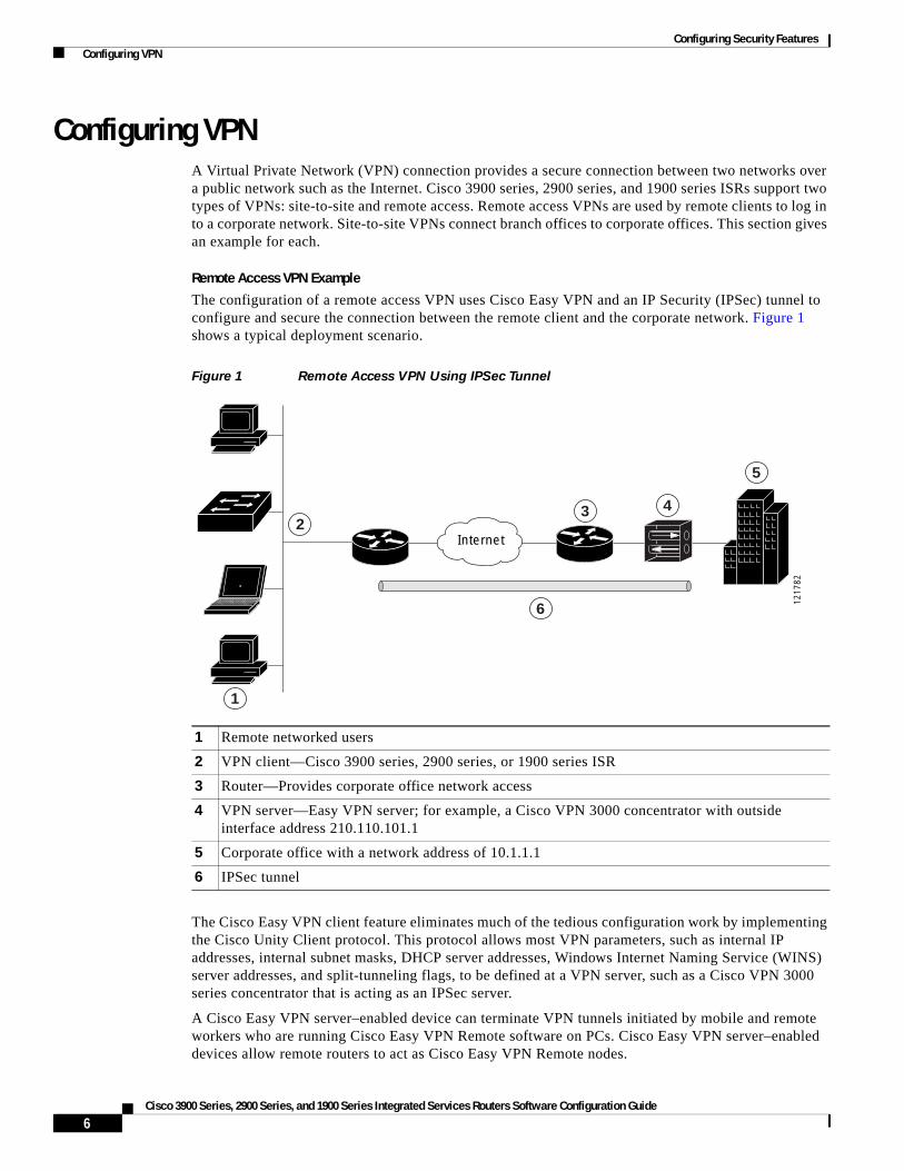
Configuring Security Features Configuring VPN
Configuring VPNA Virtual Private Network (VPN) connection provides a secure connection between two networks over a public network such as the Internet. Cisco 3900 series, 2900 series, and 1900 series ISRs support two types of VPNs: site-to-site and remote access. Remote access VPNs are used by remote clients to log in to a corporate network. Site-to-site VPNs connect branch offices to corporate offices. This section gives an example for each.
Remote Access VPN Example
The configuration of a remote access VPN uses Cisco Easy VPN and an IP Security (IPSec) tunnel to configure and secure the connection between the remote client and the corporate network. Figure 1 shows a typical deployment scenario.
Figure 1 Remote Access VPN Using IPSec Tunnel
The Cisco Easy VPN client feature eliminates much of the tedious configuration work by implementing the Cisco Unity Client protocol. This protocol allows most VPN parameters, such as internal IP addresses, internal subnet masks, DHCP server addresses, Windows Internet Naming Service (WINS) server addresses, and split-tunneling flags, to be defined at a VPN server, such as a Cisco VPN 3000 series concentrator that is acting as an IPSec server.
A Cisco Easy VPN server–enabled device can terminate VPN tunnels initiated by mobile and remote workers who are running Cisco Easy VPN Remote software on PCs. Cisco Easy VPN server–enabled devices allow remote routers to act as Cisco Easy VPN Remote nodes.
1 Remote networked users
2 VPN client—Cisco 3900 series, 2900 series, or 1900 series ISR
3 Router—Provides corporate office network access
4 VPN server—Easy VPN server; for example, a Cisco VPN 3000 concentrator with outside interface address 210.110.101.1
5 Corporate office with a network address of 10.1.1.1
6 IPSec tunnel
2
1
1217
82
Internet
3 4
5
6
6Cisco 3900 Series, 2900 Series, and 1900 Series Integrated Services Routers Software Configuration Guide

Configuring Security Features Configuring VPN
The Cisco Easy VPN client feature can be configured in one of two modes—client mode or network extension mode. Client mode is the default configuration and allows only devices at the client site to access resources at the central site. Resources at the client site are unavailable to the central site. Network extension mode allows users at the central site (where the Cisco VPN 3000 series concentrator is located) to access network resources on the client site.
After the IPSec server has been configured, a VPN connection can be created with minimal configuration on an IPSec client. When the IPSec client initiates the VPN tunnel connection, the IPSec server pushes the IPSec policies to the IPSec client and creates the corresponding VPN tunnel connection.
Note The Cisco Easy VPN client feature supports configuration of only one destination peer. If your application requires creation of multiple VPN tunnels, you must manually configure the IPSec VPN and Network Address Translation/Peer Address Translation (NAT/PAT) parameters on both the client and the server.
Cisco 3900 series, 2900 series, and 1900 series ISRs can be also configured to act as Cisco Easy VPN servers, letting authorized Cisco Easy VPN clients establish dynamic VPN tunnels to the connected network. For information on configuring Cisco Easy VPN servers, see the Easy VPN Server feature at: http://www.cisco.com/en/US/docs/ios/12_2t/12_2t8/feature/guide/ftunity.html.
Site-to-Site VPN Example
The configuration of a site-to-site VPN uses IPSec and the generic routing encapsulation (GRE) protocol to secure the connection between the branch office and the corporate network. Figure 2 shows a typical deployment scenario.
Figure 2 Site-to-Site VPN Using an IPSec Tunnel and GRE
1 Branch office containing multiple LANs and VLANs
2 Fast Ethernet LAN interface—With address 192.165.0.0/16 (also the inside interface for NAT)
3 VPN client—Cisco 3900 series, 2900 series, or 1900 series ISR
4 Fast Ethernet or ATM interface—With address 200.1.1.1 (also the outside interface for NAT)
5 LAN interface—Connects to the Internet; with outside interface address of 210.110.101.1
6 VPN client—Another router, which controls access to the corporate network
7 LAN interface—Connects to the corporate network; with inside interface address of 10.1.1.1
8 Corporate office network
9 IPSec tunnel with GRE
1217
83Internet
3
1
2 4 5 7
6
8
9
7Cisco 3900 Series, 2900 Series, and 1900 Series Integrated Services Routers Software Configuration Guide
OL-21850-01
Configuring Security Features Configuring VPN
For more information about IPSec and GRE configuration, see the Configuring Security for VPNs with IPSec” chapter of Cisco IOS Security Configuration Guide: Secure Connectivity, Release 12.4T at: http://www.cisco.com/en/US/docs/ios/sec_secure_connectivity/configuration/guide/12_4t/ sec_secure_connectivity_12_4t_book.html.
Configuration Examples
Each example configures a VPN over an IPSec tunnel, using the procedure given in the “Configure a VPN over an IPSec Tunnel” section on page 8. Then, the specific procedure for a remote access configuration is given, followed by the specific procedure for a site-to-site configuration.
The examples shown in this chapter apply only to the endpoint configuration on the Cisco 3900 series, 2900 series, and 1900 series ISRs. Any VPN connection requires both endpoints to be properly configured in order to function. See the software configuration documentation as needed to configure VPN for other router models.
VPN configuration information must be configured on both endpoints. You must specify parameters such as internal IP addresses, internal subnet masks, DHCP server addresses, and Network Address Translation (NAT).
• “Configure a VPN over an IPSec Tunnel” section on page 8
• “Create a Cisco Easy VPN Remote Configuration” section on page 17
• “Configure a Site-to-Site GRE Tunnel” section on page 20
Configure a VPN over an IPSec TunnelPerform the following tasks to configure a VPN over an IPSec tunnel:
• Configure the IKE Policy, page 9
• Configure Group Policy Information, page 10
• Apply Mode Configuration to the Crypto Map, page 12
• Enable Policy Lookup, page 13
• Configure IPSec Transforms and Protocols, page 14
• Configure the IPSec Crypto Method and Parameters, page 15
• Apply the Crypto Map to the Physical Interface, page 16
• Where to Go Next, page 17
8Cisco 3900 Series, 2900 Series, and 1900 Series Integrated Services Routers Software Configuration Guide

Configuring Security Features Configuring VPN
Configure the IKE Policy
To configure the Internet Key Exchange (IKE) policy, follow these steps, beginning in global configuration mode.
SUMMARY STEPS
1. crypto isakmp policy priority
2. encryption {des | 3des | aes | aes 192 | aes 256}
3. hash {md5 | sha}
4. authentication {rsa-sig | rsa-encr | pre-share}
5. group {1 | 2 | 5}
6. lifetime seconds
7. exit
8.
DETAILED STEPS
Command or Action Purpose
Step 1 crypto isakmp policy priority
Example:Router(config)# crypto isakmp policy 1Router(config-isakmp)#
Creates an IKE policy that is used during IKE negotiation. The priority is a number from 1 to 10000, with 1 being the highest.
Also enters the ISAKMP1 policy configuration mode.
Step 2 encryption {des | 3des | aes | aes 192 | aes 256}
Example:Router(config-isakmp)# encryption 3desRouter(config-isakmp)#
Specifies the encryption algorithm used in the IKE policy.
The example specifies 168-bit DES2.
Step 3 hash {md5 | sha}
Example:Router(config-isakmp)# hash md5Router(config-isakmp)#
Specifies the hash algorithm used in the IKE policy.
The example specifies the MD53 algorithm. The default is SHA-14.
Step 4 authentication {rsa-sig | rsa-encr | pre-share}
Example:Router(config-isakmp)# authentication pre-shareRouter(config-isakmp)#
Specifies the authentication method used in the IKE policy.
The example specifies a pre-shared key.
Step 5 group {1 | 2 | 5}
Example:Router(config-isakmp)# group 2Router(config-isakmp)#
Specifies the Diffie-Hellman group to be used in an IKE policy.
9Cisco 3900 Series, 2900 Series, and 1900 Series Integrated Services Routers Software Configuration Guide
OL-21850-01
Configuring Security Features Configuring VPN
Configure Group Policy Information
To configure the group policy, follow these steps, beginning in global configuration mode.
SUMMARY STEPS
1. crypto isakmp client configuration group {group-name | default}
2. key name
3. dns primary-server
4. domain name
5. exit
6. ip local pool {default | poolname} [low-ip-address [high-ip-address]]
DETAILED STEPS
Step 6 lifetime seconds
Example:Router(config-isakmp)# lifetime 480Router(config-isakmp)#
Specifies the lifetime, from 60 to 86400 seconds, for an IKE SA5.
Step 7 exit
Example:Router(config-isakmp)# exitRouter(config)#
Exits IKE policy configuration mode and enters global configuration mode.
1. ISAKMP = Internet Security Association Key and Management Protocol
2. DES = data encryption standard
3. MD5 = Message Digest 5
4. SHA-1 = Secure Hash standard
5. SA = security association
Command or Action Purpose
Command or Action Purpose
Step 1 crypto isakmp client configuration group {group-name | default}
Example:Router(config)# crypto isakmp client configuration group rtr-remoteRouter(config-isakmp-group)#
Creates an IKE policy group containing attributes to be downloaded to the remote client.
Also enters the ISAKMP group policy configuration mode.
Step 2 key name
Example:Router(config-isakmp-group)# key secret-passwordRouter(config-isakmp-group)#
Specifies the IKE pre-shared key for the group policy.
10Cisco 3900 Series, 2900 Series, and 1900 Series Integrated Services Routers Software Configuration Guide

Configuring Security Features Configuring VPN
Step 3 dns primary-server
Example:Router(config-isakmp-group)# dns 10.50.10.1Router(config-isakmp-group)#
Specifies the primary DNS1 server for the group.
You may also want to specify WINS2 servers for the group by using the wins command.
Step 4 domain name
Example:Router(config-isakmp-group)# domain company.comRouter(config-isakmp-group)#
Specifies group domain membership.
Step 5 exit
Example:Router(config-isakmp-group)# exitRouter(config)#
Exits IKE group policy configuration mode and enters global configuration mode.
Step 6 ip local pool {default | poolname} [low-ip-address [high-ip-address]]
Example:Router(config)# ip local pool dynpool 30.30.30.20 30.30.30.30Router(config)#
Specifies a local address pool for the group.
For details about this command and additional parameters that can be set, see Cisco IOS Dial Technologies Command Reference.
1. DNS = Domain Name System
2. WINS = Windows Internet Naming Service
Command or Action Purpose
11Cisco 3900 Series, 2900 Series, and 1900 Series Integrated Services Routers Software Configuration Guide
OL-21850-01

Configuring Security Features Configuring VPN
Apply Mode Configuration to the Crypto Map
To apply mode configuration to the crypto map, follow these steps, beginning in global configuration mode.
SUMMARY STEPS
1. crypto map map-name isakmp authorization list list-name
2. crypto map tag client configuration address [initiate | respond]
DETAILED STEPS
Command or Action Purpose
Step 1 crypto map map-name isakmp authorization list list-name
Example:Router(config)# crypto map dynmap isakmp authorization list rtr-remoteRouter(config)#
Applies mode configuration to the crypto map and enables key lookup (IKE queries) for the group policy from an AAA server.
Step 2 crypto map tag client configuration address [initiate | respond]
Example:Router(config)# crypto map dynmap client configuration address respondRouter(config)#
Configures the router to reply to mode configuration requests from remote clients.
12Cisco 3900 Series, 2900 Series, and 1900 Series Integrated Services Routers Software Configuration Guide

Configuring Security Features Configuring VPN
Enable Policy Lookup
To enable policy lookup through AAA, follow these steps, beginning in global configuration mode.
SUMMARY STEPS
1. aaa new-model
2. aaa authentication login {default | list-name} method1 [method2...]
3. aaa authorization {network | exec | commands level | reverse-access | configuration} {default | list-name} [method1 [method2...]]
4. username name {nopassword | password password | password encryption-type encrypted-password}
DETAILED STEPS
Command or Action Purpose
Step 1 aaa new-model
Example:Router(config)# aaa new-modelRouter(config)#
Enables the AAA access control model.
Step 2 aaa authentication login {default | list-name} method1 [method2...]
Example:Router(config)# aaa authentication login rtr-remote localRouter(config)#
Specifies AAA authentication of selected users at login, and specifies the method used.
This example uses a local authentication database. You could also use a RADIUS server for this. For details, see Cisco IOS Security Configuration Guide: Securing User Services, Release 2.4T and Cisco IOS Security Command Reference.
Step 3 aaa authorization {network | exec | commands level | reverse-access | configuration} {default | list-name} [method1 [method2...]]
Example:Router(config)# aaa authorization network rtr-remote localRouter(config)#
Specifies AAA authorization of all network-related service requests, including PPP, and specifies the method of authorization.
This example uses a local authorization database. You could also use a RADIUS server for this. For details, see Cisco IOS Security Configuration Guide: Securing User Services, Release 2.4T and Cisco IOS Security Command Reference.
Step 4 username name {nopassword | password password | password encryption-type encrypted-password}
Example:Router(config)# username username1 password 0 password1Router(config)#
Establishes a username-based authentication system.
This example implements a username of username1 with an encrypted password of password1.
13Cisco 3900 Series, 2900 Series, and 1900 Series Integrated Services Routers Software Configuration Guide
OL-21850-01

Configuring Security Features Configuring VPN
Configure IPSec Transforms and Protocols
A transform set represents a certain combination of security protocols and algorithms. During IKE negotiation, the peers agree to use a particular transform set for protecting data flow.
During IKE negotiations, the peers search multiple transform sets for a transform that is the same at both peers. When a transform set is found that contains such a transform, it is selected and applied to the protected traffic as a part of both peers’ configurations.
To specify the IPSec transform set and protocols, follow these steps, beginning in global configuration mode.
SUMMARY STEPS
1. crypto ipsec profile profile-name
2. crypto ipsec transform-set transform-set-name
3. crypto ipsec security-association lifetime {seconds seconds | kilobytes kilobytes}
DETAILED STEPS
Command or Action Purpose
Step 1 crypto ipsec profile profile-name
Example:Router(config)# crypto ipsec profile pro1Router(config)#
Configures an IPSec profile to apply protection on the tunnel for encryption.
Step 2 crypto ipsec transform-set transform-set-name transform1 [transform2] [transform3] [transform4]
Example:Router(config)# crypto ipsec transform-set vpn1 esp-3des esp-sha-hmacRouter(config)#
Defines a transform set—an acceptable combination of IPSec security protocols and algorithms.
See Cisco IOS Security Command Reference for detail about the valid transforms and combinations.
Step 3 crypto ipsec security-association lifetime {seconds seconds | kilobytes kilobytes}
Example:Router(config)# crypto ipsec security-association lifetime seconds 86400Router(config)#
Specifies global lifetime values used when IPSec security associations are negotiated.
See Cisco IOS Security Command Reference for details.
14Cisco 3900 Series, 2900 Series, and 1900 Series Integrated Services Routers Software Configuration Guide

Configuring Security Features Configuring VPN
Configure the IPSec Crypto Method and Parameters
A dynamic crypto map policy processes negotiation requests for new security associations from remote IPSec peers, even if the router does not know all the crypto map parameters (for example, IP address).
To configure the IPSec crypto method, follow these steps, beginning in global configuration mode.
SUMMARY STEPS
1. crypto dynamic-map dynamic-map-name dynamic-seq-num
2. set transform-set transform-set-name [transform-set-name2...transform-set-name6]
3. reverse-route
4. exit
5. crypto map map-name seq-num [ipsec-isakmp] [dynamic dynamic-map-name] [discover] [profile profile-name]
DETAILED STEPS
Command or Action Purpose
Step 1 crypto dynamic-map dynamic-map-name dynamic-seq-num
Example:Router(config)# crypto dynamic-map dynmap 1Router(config-crypto-map)#
Creates a dynamic crypto map entry and enters crypto map configuration mode.
See Cisco IOS Security Command Reference for more detail about this command.
Step 2 set transform-set transform-set-name [transform-set-name2...transform-set-name6]
Example:Router(config-crypto-map)# set transform-set vpn1Router(config-crypto-map)#
Specifies which transform sets can be used with the crypto map entry.
Step 3 reverse-route
Example:Router(config-crypto-map)# reverse-routeRouter(config-crypto-map)#
Creates source proxy information for the crypto map entry.
See Cisco IOS Security Command Reference for details.
15Cisco 3900 Series, 2900 Series, and 1900 Series Integrated Services Routers Software Configuration Guide
OL-21850-01

Configuring Security Features Configuring VPN
Apply the Crypto Map to the Physical Interface
The crypto maps must be applied to each interface through which IPSec traffic flows. Applying the crypto map to the physical interface instructs the router to evaluate all the traffic against the security associations database. With the default configurations, the router provides secure connectivity by encrypting the traffic sent between remote sites. However, the public interface still allows the rest of the traffic to pass and provides connectivity to the Internet.
To apply a crypto map to an interface, follow these steps, beginning in global configuration mode.
SUMMARY STEPS
1. interface type number
2. crypto map map-name
3. exit
DETAILED STEPS
Step 4 exit
Example:Router(config-crypto-map)# exitRouter(config)#
Returns to global configuration mode.
Step 5 crypto map map-name seq-num [ipsec-isakmp] [dynamic dynamic-map-name] [discover] [profile profile-name]
Example:Router(config)# crypto map static-map 1 ipsec-isakmp dynamic dynmapRouter(config)#
Creates a crypto map profile.
Command or Action Purpose
Command or Action Purpose
Step 1 interface type number
Example:Router(config)# interface fastethernet 4Router(config-if)#
Enters the interface configuration mode for the interface to which you are applying the crypto map.
16Cisco 3900 Series, 2900 Series, and 1900 Series Integrated Services Routers Software Configuration Guide

Configuring Security Features Configuring VPN
Where to Go Next
If you are creating a Cisco Easy VPN remote configuration, go to the “Create a Cisco Easy VPN Remote Configuration” section on page 17.
If you are creating a site-to-site VPN using IPSec tunnels and GRE, go to the “Configure a Site-to-Site GRE Tunnel” section on page 20.
Create a Cisco Easy VPN Remote ConfigurationThe router that is acting as the Cisco Easy VPN client must create a Cisco Easy VPN remote configuration and assign it to the outgoing interface.
To create the remote configuration, follow these steps, beginning in global configuration mode.
SUMMARY STEPS
1. crypto ipsec client ezvpn name
2. group group-name key group-key
3. peer {ipaddress | hostname}
4. mode {client | network-extension | network extension plus}
5. exit
6. crypto isakmp keepalive seconds
7. interface type number
8. crypto ipsec client ezvpn name [outside | inside]
9. exit
Step 2 crypto map map-name
Example:Router(config-if)# crypto map static-mapRouter(config-if)#
Applies the crypto map to the interface.
See Cisco IOS Security Command Reference for more detail about this command.
Step 3 exit
Example:Router(config-crypto-map)# exitRouter(config)#
Returns to global configuration mode.
Command or Action Purpose
17Cisco 3900 Series, 2900 Series, and 1900 Series Integrated Services Routers Software Configuration Guide
OL-21850-01
Configuring Security Features Configuring VPN
DETAILED STEPS
Command or Action Purpose
Step 1 crypto ipsec client ezvpn name
Example:Router(config)# crypto ipsec client ezvpn ezvpnclientRouter(config-crypto-ezvpn)#
Creates a Cisco Easy VPN remote configuration, and enters Cisco Easy VPN remote configuration mode.
Step 2 group group-name key group-key
Example:Router(config-crypto-ezvpn)# group ezvpnclient key secret-passwordRouter(config-crypto-ezvpn)#
Specifies the IPSec group and IPSec key value for the VPN connection.
Step 3 peer {ipaddress | hostname}
Example:Router(config-crypto-ezvpn)# peer 192.168.100.1Router(config-crypto-ezvpn)#
Specifies the peer IP address or hostname for the VPN connection.
Note A hostname can be specified only when the router has a DNS server available for hostname resolution.
Note Use this command to configure multiple peers for use as backup. If one peer goes down, the Easy VPN tunnel is established with the second available peer. When the primary peer comes up again, the tunnel is reestablished with the primary peer.
Step 4 mode {client | network-extension | network extension plus}
Example:Router(config-crypto-ezvpn)# mode clientRouter(config-crypto-ezvpn)#
Specifies the VPN mode of operation.
Step 5 exit
Example:Router(config-crypto-ezvpn)# exitRouter(config)#
Returns to global configuration mode.
Step 6 crypto isakmp keepalive seconds
Example:Router(config-crypto-ezvpn)# crypto isakmp keepalive 10Router(config)#
Enables dead peer detection messages. Time between messages is given in seconds, with a range of 10 to 3600.
18Cisco 3900 Series, 2900 Series, and 1900 Series Integrated Services Routers Software Configuration Guide
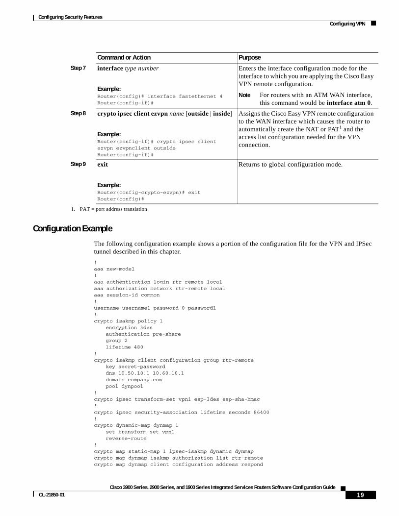
Configuring Security Features Configuring VPN
Configuration Example
The following configuration example shows a portion of the configuration file for the VPN and IPSec tunnel described in this chapter.
!aaa new-model!aaa authentication login rtr-remote localaaa authorization network rtr-remote localaaa session-id common!username username1 password 0 password1!crypto isakmp policy 1
encryption 3desauthentication pre-sharegroup 2lifetime 480
!crypto isakmp client configuration group rtr-remote
key secret-passworddns 10.50.10.1 10.60.10.1domain company.compool dynpool
!crypto ipsec transform-set vpn1 esp-3des esp-sha-hmac!crypto ipsec security-association lifetime seconds 86400!crypto dynamic-map dynmap 1
set transform-set vpn1reverse-route
!crypto map static-map 1 ipsec-isakmp dynamic dynmapcrypto map dynmap isakmp authorization list rtr-remotecrypto map dynmap client configuration address respond
Step 7 interface type number
Example:Router(config)# interface fastethernet 4Router(config-if)#
Enters the interface configuration mode for the interface to which you are applying the Cisco Easy VPN remote configuration.
Note For routers with an ATM WAN interface, this command would be interface atm 0.
Step 8 crypto ipsec client ezvpn name [outside | inside]
Example:Router(config-if)# crypto ipsec client ezvpn ezvpnclient outsideRouter(config-if)#
Assigns the Cisco Easy VPN remote configuration to the WAN interface which causes the router to automatically create the NAT or PAT1 and the access list configuration needed for the VPN connection.
Step 9 exit
Example:Router(config-crypto-ezvpn)# exitRouter(config)#
Returns to global configuration mode.
1. PAT = port address translation
Command or Action Purpose
19Cisco 3900 Series, 2900 Series, and 1900 Series Integrated Services Routers Software Configuration Guide
OL-21850-01

Configuring Security Features Configuring VPN
crypto ipsec client ezvpn ezvpnclientconnect autogroup 2 key secret-passwordmode clientpeer 192.168.100.1
!
interface fastethernet 4crypto ipsec client ezvpn ezvpnclient outsidecrypto map static-map
!interface vlan 1
crypto ipsec client ezvpn ezvpnclient inside!
Configure a Site-to-Site GRE TunnelTo configure a site-to-site GRE tunnel, follow these steps, beginning in global configuration mode.
SUMMARY STEPS
1. interface type number
2. ip address ip-address mask
3. tunnel source interface-type number
4. tunnel destination default-gateway-ip-address
5. crypto map map-name
6. exit
7. ip access-list {standard | extended} access-list-name
8. permit protocol source source-wildcard destination destination-wildcard
9. exit
DETAILED STEPS
Command or Action Purpose
Step 1 interface type number
Example:Router(config)# interface tunnel 1Router(config-if)#
Creates a tunnel interface and enters interface configuration mode.
Step 2 ip address ip-address mask
Example:Router(config-if)# 10.62.1.193 255.255.255.252Router(config-if)#
Assigns an address to the tunnel.
20Cisco 3900 Series, 2900 Series, and 1900 Series Integrated Services Routers Software Configuration Guide

Configuring Security Features Configuring VPN
Step 3 tunnel source interface-type number
Example:Router(config-if)# tunnel source fastethernet 0Router(config-if)#
Specifies the source endpoint of the router for the GRE tunnel.
Step 4 tunnel destination default-gateway-ip-address
Example:Router(config-if)# tunnel destination 192.168.101.1Router(config-if)#
Specifies the destination endpoint of the router for the GRE tunnel.
Step 5 crypto map map-name
Example:Router(config-if)# crypto map static-mapRouter(config-if)#
Assigns a crypto map to the tunnel.
Note Dynamic routing or static routes to the tunnel interface must be configured to establish connectivity between the sites. See Cisco IOS Security Configuration Guide: Secure Connectivity, Release 12.4T for details.
Step 6 exit
Example:Router(config-if)# exitRouter(config)#
Exits interface configuration mode and returns to global configuration mode.
Step 7 ip access-list {standard | extended} access-list-name
Example:Router(config)# ip access-list extended vpnstatic1Router(config-acl)#
Enters ACL1 configuration mode for the named ACL that the crypto map uses.
Step 8 permit protocol source source-wildcard destination destination-wildcard
Example:Router(config-acl)# permit gre host 192.168.100.1 host 192.168.101.1Router(config-acl)#
Specifies that only GRE traffic is permitted on the outbound interface.
Step 9 exit
Example:Router(config-acl)# exitRouter(config)#
Returns to global configuration mode.
1. ACL = access control list
Command or Action Purpose
21Cisco 3900 Series, 2900 Series, and 1900 Series Integrated Services Routers Software Configuration Guide
OL-21850-01
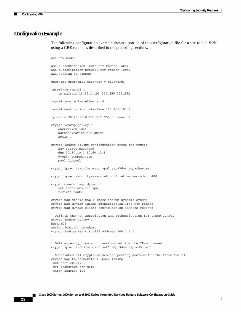
Configuring Security Features Configuring VPN
Configuration Example
The following configuration example shows a portion of the configuration file for a site-to-site VPN using a GRE tunnel as described in the preceding sections.
!aaa new-model!aaa authentication login rtr-remote localaaa authorization network rtr-remote localaaa session-id common!username username1 password 0 password1!interface tunnel 1
ip address 10.62.1.193 255.255.255.252
tunnel source fastethernet 0
tunnel destination interface 192.168.101.1
ip route 20.20.20.0 255.255.255.0 tunnel 1
crypto isakmp policy 1encryption 3desauthentication pre-sharegroup 2
!crypto isakmp client configuration group rtr-remote
key secret-passworddns 10.50.10.1 10.60.10.1domain company.compool dynpool
!crypto ipsec transform-set vpn1 esp-3des esp-sha-hmac!crypto ipsec security-association lifetime seconds 86400!crypto dynamic-map dynmap 1
set transform-set vpn1reverse-route
!crypto map static-map 1 ipsec-isakmp dynamic dynmapcrypto map dynmap isakmp authorization list rtr-remotecrypto map dynmap client configuration address respond!! Defines the key association and authentication for IPsec tunnel.crypto isakmp policy 1 hash md5 authentication pre-sharecrypto isakmp key cisco123 address 200.1.1.1!!! Defines encryption and transform set for the IPsec tunnel.crypto ipsec transform-set set1 esp-3des esp-md5-hmac !! Associates all crypto values and peering address for the IPsec tunnel.crypto map to_corporate 1 ipsec-isakmp set peer 200.1.1.1 set transform-set set1 match address 105!!
22Cisco 3900 Series, 2900 Series, and 1900 Series Integrated Services Routers Software Configuration Guide

Configuring Security Features Configuring Dynamic Multipoint VPN
! VLAN 1 is the internal home network.interface vlan 1 ip address 10.1.1.1 255.255.255.0 ip nat inside ip inspect firewall in ! Inspection examines outbound traffic.
crypto map static-mapno cdp enable
!! FE4 is the outside or Internet-exposed interfaceinterface fastethernet 4 ip address 210.110.101.21 255.255.255.0 ! acl 103 permits IPsec traffic from the corp. router as well as ! denies Internet-initiated traffic inbound. ip access-group 103 in ip nat outside no cdp enable crypto map to_corporate ! Applies the IPsec tunnel to the outside interface.!! Utilize NAT overload in order to make best use of the ! single address provided by the ISP.ip nat inside source list 102 interface Ethernet1 overloadip classlessip route 0.0.0.0 0.0.0.0 210.110.101.1no ip http server!!! acl 102 associated addresses used for NAT.access-list 102 permit ip 10.1.1.0 0.0.0.255 any! acl 103 defines traffic allowed from the peer for the IPsec tunnel.access-list 103 permit udp host 200.1.1.1 any eq isakmpaccess-list 103 permit udp host 200.1.1.1 eq isakmp anyaccess-list 103 permit esp host 200.1.1.1 any! Allow ICMP for debugging but should be disabled because of security implications.access-list 103 permit icmp any any access-list 103 deny ip any any ! Prevents Internet-initiated traffic inbound.! acl 105 matches addresses for the IPsec tunnel to or from the corporate network.access-list 105 permit ip 10.1.1.0 0.0.0.255 192.168.0.0 0.0.255.255no cdp run
Configuring Dynamic Multipoint VPNThe Dynamic Multipoint VPN (DMVPN) feature allows users to better scale large and small IP Security (IPsec) VPNs by combining GRE tunnels, IPsec encryption, and Next Hop Resolution Protocol (NHRP).
For additional information about configuring DMVPN, see the “Dynamic Multipoint VPN” section of Cisco IOS Security Configuration Guide: Secure Connectivity, Release 12.4T at: http://www.cisco.com/en/US/docs/ios/sec_secure_connectivity/configuration/guide/12_4t/ sec_secure_connectivity_12_4t_book.html.
23Cisco 3900 Series, 2900 Series, and 1900 Series Integrated Services Routers Software Configuration Guide
OL-21850-01

Configuring Security Features Configuring Group Encrypted Transport VPN
Configuring Group Encrypted Transport VPNGroup Encrypted Transport (GET) VPN is a set of features that are necessary to secure IP multicast group traffic or unicast traffic over a private WAN that originates on or flows through a Cisco IOS device. GET VPN combines the keying protocol Group Domain of Interpretation (GDOI) with IPsec encryption to provide users with an efficient method of securing IP multicast traffic or unicast traffic. GET VPN enables the router to apply encryption to nontunneled (that is, “native”) IP multicast and unicast packets and eliminates the requirement to configure tunnels to protect multicast and unicast traffic.
By removing the need for point-to-point tunnels, meshed networks can scale higher while maintaining network-intelligence features that are critical to voice and video quality, such as QoS, routing, and multicast. GET VPN offers a new standards-based IP security (IPsec) security model that is based on the concept of “trusted” group members. Trusted member routers use a common security methodology that is independent of any point-to-point IPsec tunnel relationship.
For additional information about configuring GET VPN, see Cisco Group Encrypted Transport VPN at: http://www.cisco.com/en/US/docs/ios/12_4t/12_4t11/htgetvpn.html.
24Cisco 3900 Series, 2900 Series, and 1900 Series Integrated Services Routers Software Configuration Guide

Configuring Security Features Configuring Group Encrypted Transport VPN
CCDE, CCENT, CCSI, Cisco Eos, Cisco HealthPresence, Cisco IronPort, the Cisco logo, Cisco Nurse Connect, Cisco Pulse, Cisco SensorBase, Cisco StackPower, Cisco StadiumVision, Cisco TelePresence, Cisco Unified Computing System, Cisco WebEx, DCE, Flip Channels, Flip for Good, Flip Mino, Flipshare (Design), Flip Ultra, Flip Video, Flip Video (Design), Instant Broadband, and Welcome to the Human Network are trademarks; Changing the Way We Work, Live, Play, and Learn, Cisco Capital, Cisco Capital (Design), Cisco:Financed (Stylized), Cisco Store, Flip Gift Card, and One Million Acts of Green are service marks; and Access Registrar, Aironet, AllTouch, AsyncOS, Bringing the Meeting To You, Catalyst, CCDA, CCDP, CCIE, CCIP, CCNA, CCNP, CCSP, CCVP, Cisco, the Cisco Certified Internetwork Expert logo, Cisco IOS, Cisco Lumin, Cisco Nexus, Cisco Press, Cisco Systems, Cisco Systems Capital, the Cisco Systems logo, Cisco Unity, Collaboration Without Limitation, Continuum, EtherFast, EtherSwitch, Event Center, Explorer, Follow Me Browsing, GainMaker, iLYNX, IOS, iPhone, IronPort, the IronPort logo, Laser Link, LightStream, Linksys, MeetingPlace, MeetingPlace Chime Sound, MGX, Networkers, Networking Academy, PCNow, PIX, PowerKEY, PowerPanels, PowerTV, PowerTV (Design), PowerVu, Prisma, ProConnect, ROSA, SenderBase, SMARTnet, Spectrum Expert, StackWise, WebEx, and the WebEx logo are registered trademarks of Cisco Systems, Inc. and/or its affiliates in the United States and certain other countries.
All other trademarks mentioned in this document or website are the property of their respective owners. The use of the word partner does not imply a partnership relationship between Cisco and any other company. (0910R)
Any Internet Protocol (IP) addresses used in this document are not intended to be actual addresses. Any examples, command display output, and figures included in the document are shown for illustrative purposes only. Any use of actual IP addresses in illustrative content is unintentional and coincidental. © 2009-2010 Cisco Systems, Inc. All rights reserved.
25Cisco 3900 Series, 2900 Series, and 1900 Series Integrated Services Routers Software Configuration Guide
OL-21850-01

Configuring Security Features Configuring Group Encrypted Transport VPN
26Cisco 3900 Series, 2900 Series, and 1900 Series Integrated Services Routers Software Configuration Guide

Unified Communications on Cisco Integrated Services Routers
The following sections describe Unified Communications (UC) application services that are supported on Cisco 3900 series and 2900 series integrated services routers (ISRs).
• Modules and Interface Cards, page 2
• Call Control, page 2
– Cisco Unified Communications Manager Express, page 2
– Unified Survivable Remote Site Telephony, page 3
– Cisco Unified SIP Proxy (CUSP), page 4
– Gatekeeper, page 4
• Call Control Protocols, page 4
– Trunk-side Protocols, page 4
– Line-side Protocols, page 5
• Unified Communications Gateways, page 6
– TDM Gateways, page 7
– Cisco Unified Border Element, page 8
– Unified Messaging Gateway, page 8
• IP Media Services, page 9
– Conferencing, Transcoding and Media Termination Point (MTP), page 9
– RSVP Agent, page 9
– Trusted Relay Point (TRP), page 9
– Packet Voice Data Module, page 10
• Voice Security, page 10
Americas Headquarters:Cisco Systems, Inc., 170 West Tasman Drive, San Jose, CA 95134-1706 USA

Unified Communications on Cisco Integrated Services Routers Modules and Interface Cards
– UC Trusted Firewall, page 10
– Signaling and Media Authentication and Encryption, page 11
– Virtual Route Forward, page 11
• Applications and Application Interfaces (APIs), page 11
– Cisco Unity Express, page 12
– Voice XML, page 12
– Hoot-n-Holler, page 13
– Cisco Application Extension Platform, page 13
– APIs, page 13
• Online Insertion and Removal, page 14
Modules and Interface CardsCisco 3900 series and 2900 series ISRs support Unified Communications (UC) modules and interface cards in the following slots:
• Next-generation packet voice/data module (PVDM3)
• Service module (SM)
• Enhanced high-speed WAN interface card (EHWIC)
Note The PVDM3 slot and the SM slot are not backwards compatible with legacy modules. Legacy modules require an adapter for installation in these slots.
For a list of supported UC modules and interface cards see Module Support on Cisco Integrated Services Routers Generation 2.
Call ControlThe Cisco 3900 series and Cisco 2900 series ISRs support the following types of call control applications and Cisco Voice solutions:
• Cisco Unified Communications Manager Express, page 2
• Unified Survivable Remote Site Telephony, page 3
• Cisco Unified SIP Proxy (CUSP), page 4
• Gatekeeper, page 4
Cisco Unified Communications Manager ExpressCisco Unified Communications Manager Express (CME) is a feature-rich entry-level IP telephony solution that is integrated directly into Cisco IOS software. Cisco Unified CME allows small business customers and autonomous small enterprise branch offices to deploy voice, data, and IP telephony on a single platform for small offices, thereby streamlining operations and lowering network costs.
2Cisco 3900 Series, 2900 Series, and 1900 Series Integrated Services Routers Software Configuration Guide
Unified Communications on Cisco Integrated Services Routers Call Control
Cisco Unified CME is ideal for customers who have data connectivity requirements and also have a need for a telephony solution in the same office. Whether offered through a service provider's managed services offering or purchased directly by a corporation, Cisco Unified CME offers most of the core telephony features required in the small office, and also many advanced features not available with traditional telephony solutions. The ability to deliver IP telephony and data routing by using a single converged solution allows customers to optimize their operations and maintenance costs, resulting in a very cost-effective solution that meets office needs.
A Cisco Unified CME system is extremely flexible because it is modular. A Cisco Unified CME system consists of a router that serves as a gateway and one or more VLANs that connect IP phones and phone devices to the router.
See Cisco Unified Communications Manager Express (CME) Overview at: http://www.cisco.com/en/US/docs/voice_ip_comm/cucme/admin/configuration/guide/cmeover.html.
Unified Survivable Remote Site TelephonyCisco Unified Survivable Remote Site Telephony (SRST) enables Cisco routers to provide call-handling support for Cisco IP phones when they lose connection to Cisco Unified Communications Manager (CUCM) installations, or when the WAN connection is down. In a centralized deployment, under normal conditions, Cisco IP phones are controlled by the Cisco Unified Communications Manager located at a central site like the headquarters of an enterprise. When connection to CUCM breaks, for example as result of a failure in the network, Unified SRST automatically detects the failure and auto configures the router for providing backup call processing functionality.
During a WAN failure, the router allows all the phones to re-register to the remote site router in SRST mode, allowing all inbound and outbound dialing to be routed off to the PSTN (on a backup Foreign Exchange Office (FXO), BRI or Primary Rate Interface (PRI) connection).
Unified SRST provides redundancy for both Cisco IP as well as Analog phones to ensure that the telephone system remains operational during network failures. Both Skinny Client Control Protocol (SCCP) and session initiation protocol (SIP) based Cisco IP phones are supported with the Unified SRST.
When the WAN link or connection to the Cisco Unified Communications Manager is restored, call handling reverts back to the Cisco Unified Communications Manager automatically without need for any human intervention.
For general Unified SRST information, see Cisco Unified SRST System Administrator Guide.
• For information on how the H.323 and Media Gateway Control Protocol (MGCP) call control protocols relate to SRST, see Cisco Unified SRST System Administrator Guide:
– For H.323, see H.323 Gateways and SRST at Cisco.com.
– For MGCP, see MGCP Gateways and SRST at Cisco.com.
• Configurations of major SRST features are provided in the following chapters of the Cisco Unified SRST System Administrator Guide:
– “Setting up the Network”
– “Setting up Cisco Unified IP Phones”
– “Setting up Call Handling”
– “Configuring Additional Call Features”
– “Setting up Secure SRST”
– “Integrating Voice Mail with Cisco Unified SRST”
3Cisco 3900 Series, 2900 Series, and 1900 Series Integrated Services Routers Software Configuration Guide
OL-21850-01

Unified Communications on Cisco Integrated Services Routers Call Control Protocols
For SIP-specific SRST information, see Cisco Unified SIP SRST System Administrator Guide. To configure SIP SRST features, see the Cisco Unified SIP SRST 4.1 chapter.
Cisco Unified SIP Proxy (CUSP)The Cisco Unified SIP Proxy (CUSP) is a high-performance, highly available Session Initiation Protocol (SIP) server for centralized routing and SIP signaling normalization. By forwarding requests between call-control domains, the Cisco Unified SIP Proxy provides the means for routing sessions within enterprise and service provider networks.
To configure CUSP features, see Configuring Cisco Unified SIP Proxy Version 1.1.3 for an Enterprise Network at: http://www.cisco.com/en/US/docs/voice_ip_comm/cusp/rel1_1_3/configuration/guide/cuspgd113.html
GatekeeperAn H.323 Gatekeeper is an optional node in an H.323 network that manages endpoints (such as H.323 terminals, gateways, and Multipoint Control Units (MCUs), as well as Cisco Unified Communications Manager Express and Cisco Unified Communications Manager clusters). An H.323 Gatekeeper provides these endpoints with call routing and call admission control functions. The endpoints communicate with the Gatekeeper using the H.323 Registration Admission Status (RAS) protocol.
The H.323 Gatekeeper is a special Cisco IOS software image that runs on the Cisco ISR platforms and the AS5350XM and AS5400XM Universal Gateway platforms. The Cisco IOS H.323 Gatekeeper is an application that acts as the point of control for a variety of voice and video components that can be attached to an IP network such as IP telephony devices, IP-PSTN gateways, H.323 video conferencing endpoints, and H.323 multipoint control units while facilitating buildout of large-scale multimedia service networks.
To configure Gatekeeper features, see Configuring H.323 Gatekeepers and Proxies at: http://www.cisco.com/en/US/docs/ios/12_3/vvf_c/cisco_ios_h323_configuration_guide /old_archives_h323/5gkconf.html.
Call Control ProtocolsThe Cisco 3900 series and Cisco 2900 series ISRs support the following type of call control protocols:
• Trunk-side Protocols, page 4
• Line-side Protocols, page 5
Trunk-side ProtocolsThe Cisco 3900 series and Cisco 2900 series ISRs support the following trunk-side call control protocols:
• Session Initiation Protocol (SIP), page 5
• Media Gateway Control Protocol (MGCP), page 5
• H.323, page 5
4Cisco 3900 Series, 2900 Series, and 1900 Series Integrated Services Routers Software Configuration Guide
Unified Communications on Cisco Integrated Services Routers Call Control Protocols
Session Initiation Protocol (SIP)
Session Initiation Protocol (SIP) is a peer-to-peer, multimedia signaling protocol developed in the IETF (IETF RFC 3261). Session Initiation Protocol is ASCII-based. It resembles HTTP, and it reuses existing IP protocols (such as DNS and SDP) to provide media setup and tear down. See Cisco IOS SIP Configuration Guide for more information.
For router configuration information under SIP, see Basic SIP Configuration chapter of the Cisco IOS SIP Configuration Guide.
Voice gateways provide voice security through SIP enhancements within the Cisco IOS Firewall. SIP inspect functionality (SIP packet inspection and detection of pin-hole openings) is provided, as well as protocol conformance and application security. The user is given more granular control on the policies and security checks applied to SIP traffic, and capability to filter out unwanted messages. For more information, see “Cisco IOS Firewall: SIP Enhancements: ALG and AIC” at Cisco.com.
Media Gateway Control Protocol (MGCP)
Media Gateway Control Protocol (MGCP) RFC 2705 defines a centralized architecture for creating multimedia applications, including Voice over IP (VoIP). See Cisco IOS MGCP and Related Protocols Configuration Guide for more information.
ISRs are configured primarily as residential gateways (RGWs) under MGCP. For residential gateway configuration information, see the Configuring an RGW section of the Basic MGCP Configuration chapter of Cisco IOS MGCP and Related Protocols Configuration Guide.
H.323
H.323 is an umbrella recommendation from the International Telecommunication Union (ITU) that defines the protocols to provide voice and video communication sessions on a packet network. The H.323 standard addresses call signaling and control, multimedia transport and control, and bandwidth control for point-to-point and multi-point sessions. See Cisco IOS H.323 Configuration Guide for more information about H.323.
For router configuration information, see the Configuring H.323 Gateways chapter of Cisco IOS H.323 Configuration Guide.
Line-side ProtocolsThe Cisco 3900 series and Cisco 2900 series ISRs support the following line-side call control protocols:
• SCCP-Controlled Analog Ports with Supplementary Features, page 6
• Session Initiation Protocol (SIP), page 6
5Cisco 3900 Series, 2900 Series, and 1900 Series Integrated Services Routers Software Configuration Guide
OL-21850-01

Unified Communications on Cisco Integrated Services Routers Unified Communications Gateways
SCCP-Controlled Analog Ports with Supplementary Features
Voice gateway ISRs support the Cisco Skinny Client Control Protocol (SCCP), which supplies basic and supplementary features on analog voice ports that are controlled by Cisco Unified Communications Manager or by a Cisco Unified Communications Manager Express system. Supported features include:
• Audible message waiting indication
• Call forwarding options
• Call park/pickup options
• Call transfer
• Call waiting
• Caller ID
• 3-party conference calls
• Redial
• Speed dial options
For more information on the features supported and their configuration, see SCCP Controlled Analog (FXS) Ports with Supplementary Features in Cisco IOS Gateways at Cisco.com.
Session Initiation Protocol (SIP)
Session Initiation Protocol (SIP) is a peer-to-peer, multimedia signaling protocol developed in the IETF (IETF RFC 3261). Session Initiation Protocol is ASCII-based. It resembles HTTP, and it reuses existing IP protocols (such as DNS and SDP) to provide media setup and tear down. See Cisco IOS SIP Configuration Guide for more information.
For router configuration information under SIP, see the Basic SIP Configuration chapter of Cisco IOS SIP Configuration Guide.
Voice gateways provide voice security through SIP enhancements within the Cisco IOS Firewall. SIP inspect functionality (SIP packet inspection and detection of pin-hole openings) is provided, as well as protocol conformance and application security. The user is given more granular control on the policies and security checks applied to SIP traffic, and capability to filter out unwanted messages. For more information, see “Cisco IOS Firewall: SIP Enhancements: ALG and AIC” at Cisco.com.
Unified Communications GatewaysThe Cisco 3900 series and Cisco 2900 series ISRs support the following Unified Communication gateways:
• TDM Gateways, page 7
• Cisco Unified Border Element, page 8
• Unified Messaging Gateway, page 8
6Cisco 3900 Series, 2900 Series, and 1900 Series Integrated Services Routers Software Configuration Guide
Unified Communications on Cisco Integrated Services Routers Unified Communications Gateways
TDM GatewaysThe Cisco 3900 series and Cisco 2900 series ISRs support the following type of time-division multiplexing (TDM) gateways:
• Voice Gateways, page 7
• Video Gateway, page 7
Voice Gateways
Cisco IOS voice gateways connect TDM equipment such as private branch exchanges (PBXs) and the PSTN to VoIP packet networks. The Cisco ISR voice gateway routers support the widest range of packet telephony-based voice interfaces and signaling protocols within the industry, providing connectivity support for more than 90 percent of all PBXs and public-switched-telephone-network (PSTN) connection points. Signaling support includes T1/E1 Primary Rate Interface (PRI), T1 channel associated signaling (CAS), E1-R2, T1/E1 QSIG protocol, T1 Feature Group D (FGD), Basic Rate Interface (BRI), foreign exchange office (FXO), ear and mouth (E&M), and foreign exchange station (FXS). These voice gateway are highly scalable from just a few analog connections to up to 24 T1 or E1 interfaces.
The Cisco ISR series voice gateway routers can communicate with the Cisco Unified Communications Manager using Session Initiation Protocol (SIP), H.323, or Media Gateway Control Protocol (MGCP). The Cisco IOS voice gateway routers can also connect directly to other Cisco voice gateway routers using SIP or H.323 and to various other VoIP destinations and call agents.
For more information, see ISDN Voice, Video and Data Call Switching with Router TDM Switching Features at: http://www.cisco.com/en/US/tech/tk652/tk653/technologies_tech_note09186a00804794c6.shtml.
For details about tuning voice ports, see Cisco IOS Voice Port Configuration Guide, Release 12.4T at Cisco.com at: http://www.cisco.com/en/US/docs/ios/voice/voiceport/configuration/guide/12_4t/vp_12_4t_book.html.
Video Gateway
The Integrated Data, Voice, and Video Services for ISDN Interfaces feature allows multimedia communications between H.320 endpoints and H.323, SIP, or Skinny Client Control Protocol (SCCP) endpoints.
See Integrating Data, Voice, and Video Services for ISDN Interfaces at Cisco.com for details about setting up a Video gateway (http://www.cisco.com/en/US/docs/ios/12_4t/12_4t11/h320gw.html.)
See Cisco IOS H.323 Configuration Guide, Release 12.4T at Cisco.com for details about the H.323 protocol (http://www.cisco.com/en/US/docs/ios/voice/h323/configuration/guide/12_4t/ vh_12_4t_book.html).
7Cisco 3900 Series, 2900 Series, and 1900 Series Integrated Services Routers Software Configuration Guide
OL-21850-01

Unified Communications on Cisco Integrated Services Routers Unified Communications Gateways
Cisco Unified Border ElementCisco Unified Border Element (Cisco UBE) is a session border controller that provides the necessary services for interconnecting independent Unified Communications networks securely, flexibly, and reliably. Media packets can flow either through the gateway (thus hiding the networks from each other) or around the border element, if so configured. The Cisco UBE is typically used to connect enterprise networks to service provider SIP trunks, or to interconnect different nodes in an enterprise network where protocol or feature incompatibilities exist, or where extra secure demarcation between segments of the network is needed.
The Cisco Unified Border Element provides the following network-to-network interconnect capabilities:
• Session Management: Real-time session setup and tear-down services, call admission control, ensuring QoS, routing of calls if an error occurs, statistics, and billing.
• Interworking: H.323 and SIP protocol conversion; SIP normalization; DTMF conversion, transcoding, codec filtering
• Demarcation: Point of fault isolation, topology hiding, establishing and maintaining network borders, gathering statistics, and billing information on each network segment separately
• Security: Provides interworking between encrypted and non-encrypted network segment, SIP registration services, DOS protection, authentication services, and toll fraud protection on H.323 or SIP trunks.
See Cisco Unified Border Element Configuration Guide at Cisco.com for more information, http://www.cisco.com/en/US/docs/ios/voice/cube/configuration/guide/vb_book/vb_book.html.
Unified Messaging GatewayThe Cisco Unified Messaging Gateway provides an open and secure method of intelligently routing messages and exchanging subscriber and directory information within a unified messaging network. It acts as the central hub in a network of Cisco unified messaging solutions and third-party gateways that interface with older voicemail systems.
Unified Messaging Gateway is ideal for companies that need the following key features:
• Scales the unified messaging network as required for branch-office customers and larger distributed enterprises
• Simplifies configuration tasks and centralize voicemail system management
• Transparently integrates Cisco Unified Communications solutions into existing voicemail installations
• Integrates small to large-scale unified messaging deployments that consist of more than five Cisco Unity Express systems.
• Integrates up to 10,000 mixed Cisco Unity Express, Cisco Unity, and Cisco Unity Connection systems.
See Cisco Unified Messaging Gateway 1.0 Command Reference at Cisco.com for more information, http://www.cisco.com/en/US/docs/voice_ip_comm/umg/rel1_0/command/reference/UMG_1.0_CmdRef.html.
8Cisco 3900 Series, 2900 Series, and 1900 Series Integrated Services Routers Software Configuration Guide

Unified Communications on Cisco Integrated Services Routers IP Media Services
IP Media ServicesThe Cisco 3900 series and Cisco 2900 series ISRs support the following media services:
• Conferencing, Transcoding and Media Termination Point (MTP), page 9
• RSVP Agent, page 9
• Trusted Relay Point (TRP), page 9
Conferencing, Transcoding and Media Termination Point (MTP)Cisco Enhanced Conferencing and Transcoding for Voice Gateway Routers provides conferencing and transcoding capabilities in Cisco IOS Software-based gateways using the onboard Cisco Packet Voice/Fax Digital Signal Processor Modules on the Cisco voice gateway routers. This capability is also supported on Cisco voice gateway router platforms using the Cisco IP Communications Voice/Fax Network Module and the Cisco IP Communications High-Density Digital Voice/Fax Network Module. This feature is delivered in Cisco IOS Software and operates in conjunction with Cisco CallManager.
See Configuring Enhanced Conferencing and Transcoding for Voice Gateway Routers at Cisco.com for configuration information, http://www.cisco.com/en/US/docs/ios/12_3/vvf_c/interop/intcnf2.html.
RSVP AgentThe RSVP Agent feature implements a Resource Reservation Protocol (RSVP) agent on Cisco IOS voice gateways that support Cisco Unified Communications Manager Version 5.0.1. The RSVP agent enables Cisco Unified Communications Manager to provide resource reservation for voice and video media to ensure QoS and call admission control (CAC). Cisco Unified Communications Manager controls the RSVP agent through Skinny Client Control Protocol (SCCP). This signaling is independent of the signaling protocol used for the call so SCCP, SIP, H.323, and MGCP calls can all use the RSVP agent.
Benefits of this feature include the following:
• Improves flexibility and scalability of bandwidth management in a meshed network by decentralizing call admission control
• Provides method of managing unpredictable bandwidth requirements of video media
• Enables RSVP across WAN for Cisco IP phones and other devices that do not support RSVP
See Configuring the RSVP Agent at Cisco.com for information, http://www.cisco.com/en/US/docs/ios/12_3/vvf_c/interop/int_rsvp.html.
Trusted Relay Point (TRP)The Cisco Unified Communications system can be deployed in a network virtualization environment. Cisco Unified Communications Manager enables the insertion of trusted relay points (TRPs). The insertion of TRPs into the media path constitutes a first step toward VoIP deployment within a virtual network.
See Media Resource Management at Cisco.com for more information, http://www.cisco.com/en/US/docs/voice_ip_comm/cucm/admin/7_0_1/ccmsys/ a05media.html#wp1056492.
9Cisco 3900 Series, 2900 Series, and 1900 Series Integrated Services Routers Software Configuration Guide
OL-21850-01

Unified Communications on Cisco Integrated Services Routers Voice Security
Packet Voice Data ModuleThe Next-Generation Packet Voice Data Module (PVDM3) digital signal processor (DSP) modules provide up to four times the density (per slot) of existing audio applications on Cisco voice gateway routers. One universal DSP image for these DSP modules provides resources for time-division multiplexing-to-Internet Protocol (TDM-to-IP) gateway functionality for digital and analog interfaces, audio transcoding, and audio conferencing.
This enhanced DSP architecture accommodates a new packet-processing engine for rich-media voice applications and supports the TDM voice framework used by the PVDM2 module. The PDVM3 has a Gigabit Ethernet interface with a Multi-Gigabit Fabric to increase IP throughput, and a DSP hardware-based health monitor provides DSP failure detection that is ten times faster than existing technology.
To configure PVDM3 features, see the “Configuring Next-Generation High-Density PVDM3 Modules” section on page 1.
Voice SecurityThe Cisco 3900 series and Cisco 2900 series ISRs support the following voice security services:
• UC Trusted Firewall, page 10
• Signaling and Media Authentication and Encryption, page 11
• Virtual Route Forward, page 11
UC Trusted FirewallCisco Unified Communications Trusted Firewall Control pushes intelligent services onto the network through a Trusted Relay Point (TRP). Firewall traversal is accomplished using Simple Session Traversal Utilities for NAT (STUN) on a TRP co-located with a Cisco Unified Communications Manager Express (Cisco Unified CME), Cisco Unified Border Element (CUBE), Media Termination Point (MTP), Transcoder, or Conference Bridge.
Firewall traversal for Unified Communications is often a difficult problem. Voice over IP (VoIP) protocols use many ports for a single communication session and most of these ports (those used for media, H.245 and so forth) are ephemeral. It is not possible to configure static rules for such ports, as they fall in a large range. Cisco Unified Trusted Firewall opens ports dynamically based on the conversation of trusted end-points.
By using UC Trusted Firewall in the network, following things can be achieved:
• Firewall can be made independent of protocol, because only TRP, which is controlled by Call Control needs to be enhanced for various protocols. Firewall does not need to change.
• Increase firewall performance while opening firewall ports in the media path dynamically when a VoIP call is made between two endpoints.
• Simplify the firewall policy configuration and integration of firewall policy generation with call control.
• Provide a solution without compromising on network security.
To configure UC Trusted Firewall features, see Cisco Unified Communications Trusted Firewall Control at: http://www.cisco.com/en/US/docs/voice_ip_comm/cucme/feature/guide/TrustedFirewallControll.html.
10Cisco 3900 Series, 2900 Series, and 1900 Series Integrated Services Routers Software Configuration Guide
Unified Communications on Cisco Integrated Services Routers Applications and Application Interfaces (APIs)
Signaling and Media Authentication and EncryptionThe Media and Signaling Authentication and Encryption Feature for Cisco IOS MGCP Gateways feature provides support for Cisco Secure Survivable Remote Site Telephony (SRST) and voice security features that include authentication, integrity, and encryption of voice media and related call control signaling.
See Media and Signaling Authentication and Encryption Feature on Cisco IOS MGCP Gateways at Cisco.com for configuration information, http://www.cisco.com/en/US/docs/ios/12_3t/12_3t11/feature/guide/gtsecure.html.
The Media and Signaling Encryption (SRTP/TLS) on DSP Farm Conferencing feature provides secure conferencing capability for Cisco Unified Communications Manager (Unified CM) networks, including authentication, integrity and encryption of voice media and related call control signaling to and from the digital signal processor (DSP) farm.
See Media and Signaling Encryption (SRTP/TLS) on DSP Conferencing Farm at Cisco.com for configuration information, http://www.cisco.com/en/US/docs/ios/12_4t/12_4t15/itsdsp.html.
See SIP: SIP Support for SRTP at Cisco.com for configuration information, http://www.cisco.com/en/US/docs/ios/12_4t/12_4t15/srtpstub.html#wp1008975.
Virtual Route Forward Virtual Route Forward (VRF) is the technique to create multiple virtual networks within a single network entity. In a single network component, we can create multiple VRFs to create the isolation among each other. In our regular deployment of Unified Communication, we create different VLANs for voice and data to separate traffics. This is Layer-2 virtualization. In conjunction with VAN support, Cisco UC also supports Layer-3 virtualization through VRF for both voice and data.
In a typical UC deployment, hard phones are typically in Voice Segments and PCs are in Data Segments. PCs are inherently un-trusted devices in the network. Mechanisms based on’s rely on port numbers and there is no way to ensure only ‘trusted’ media enters UC Segment. VRF implementations in ISR can create single voice network and multiple data networks, which consolidate voice communication into one logically partitioned network to separate voice and data communication on a converged multi-media network.
To configure Virtual Route Forward features, see Virtual Route Forwarding Design Guide at: http://www.cisco.com/en/US/docs/voice_ip_comm/cucme/vrf/design/guide/vrfDesignGuide.html.
Applications and Application Interfaces (APIs)The Cisco 3900 series and Cisco 2900 series ISRs support the following applications and application interfaces:
• Cisco Unity Express, page 12
• Voice XML, page 12
• Hoot-n-Holler, page 13
• Hoot-n-Holler, page 13
• Cisco Application Extension Platform, page 13
• APIs, page 13
11Cisco 3900 Series, 2900 Series, and 1900 Series Integrated Services Routers Software Configuration Guide
OL-21850-01

Unified Communications on Cisco Integrated Services Routers Applications and Application Interfaces (APIs)
Cisco Unity ExpressCisco Unity Express provides integrated messaging, voicemail, Automated Attendant services, and optional interactive voice response (IVR) for the small and medium-sized office or branch office. The application is delivered on either a network module or advanced integration module, both of which are supported on a variety of voice-enabled integrated services routers.
This application is ideal for companies that need the following:
• Integrated messaging, voicemail, Automated Attendant, or interactive-voice-response (IVR) services at the branch or small office to support local users
• Up to 250 users per site
• Networking of multiple Cisco Unity Express systems for easy management of messages across sites
The application features follow:
• Affordable messaging, greeting services for increased customer service, and rich employee communications.
• Intuitive telephone prompts and a web-based interface provide fast, convenient voicemail, and Automated Attendant administration.
• Cisco Unity Express can view, sort, search, and play back voice messages using the display of a Cisco Unified IP Phone or your e-mail client.
• Scalable solution from 4 to 16 concurrent voicemail or Automated Attendant calls and 12 to 250 mailboxes.
• Deployable with Cisco Unified Communications Manager Express, Cisco Unified Communications Manager, Cisco Unity, and Cisco Unity Connection systems.
See the Unity Express Configuration guides at Cisco.com for more information, http://www.cisco.com/en/US/products/sw/voicesw/ps2237/products_installation_and_configuration_guides_list.html.
Voice XMLCisco IOS unified communications routers provide many rich voice capabilities, including Voice Extensible Markup Language (VoiceXML) browser services. VoiceXML is an open-standard markup language used to create voice-enabled Web browsers and interactive-voice-response (IVR) applications. Available on a wide range of Cisco IOS Software voice gateways, these services are used in conjunction with a VoiceXML application service such as Cisco Unified Customer Voice Portal (CVP). Other VoiceXML applications can also use the Cisco IOS routers as a VoiceXML browser to provide IVR services to callers.
To configure a Voice XML gateway on the Cisco 3900 series or Cisco 2900 series Integrated Services Router see: http://www.cisco.com/en/US/docs/ios/voice/ivr/configuration/guide/ivrapp01.html#wp1010676.
Cisco IOS voice features having to do with Cisco IOS Tcl IVR and VoiceXML for developers and network administrators who are installing, configuring, and maintaining a Tcl or VoiceXML application on a Cisco voice gateway are provided at:
http://www.cisco.com/en/US/docs/ios/voice/ivr/configuration/guide/Roadmap.html#wp1008602.
12Cisco 3900 Series, 2900 Series, and 1900 Series Integrated Services Routers Software Configuration Guide

Unified Communications on Cisco Integrated Services Routers Applications and Application Interfaces (APIs)
Hoot-n-HollerCisco Hoot-n-Holler network solution uses Cisco IOS Multicast and Cisco IOS Voice-over-IP technologies. The Cisco IP-based Hoot network uses bandwidth when it is in use; when it is not, the same bandwidth can be used to carry other traffic. The IP backbone interoperates with existing Hoot & Holler end-station equipment, such as microphones, turrets, Hoot phones, or squawk boxes, as well as bridges and mixers, for a seamless transition. Brokerage houses can adapt this solution to eliminate costly private telco circuits and reap significant operational cost savings—up to millions of dollars per year—for a rapid return on investment.
See Cisco Hoot and Holler over IP at Cisco.com for information, http://www.cisco.com/en/US/docs/ios/12_2/voice/configuration/guide/vvfhhip.html
See Cisco IOS Multicast for Hoot & Holler Networks at Cisco.com for information, http://www.cisco.com/en/US/netsol/ns340/ns394/ns165/ns70/networking_solutions_white_paper09186a00800a3e6c.shtml
Cisco Application Extension PlatformCisco Application Extension Platform (AXP) is an open network platform for application development, integration and hosting. It is a service module on the Cisco Integrated Services Router (ISR). AXP realizes the “Network as a Platform” vision of Cisco while bringing collaborative partnerships and accelerating innovation. Cisco AXP offers the following features:
• Linux-based integration environment to develop applications that run on routers.
• Certified libraries to implement C, Python, Perl, and Java applications (http web server and SSH are also supported).
• Service APIs for integrating applications into the network.
• Multiple applications can run in their own virtual instance with the ability to segment and guarantee CPU, memory, and disk resources.
See Cisco Application eXtension Platform Quick Start Guide at Cisco.com for Getting Started information, http://www.cisco.com/en/US/docs/interfaces_modules/services_modules/ax/1.0/quick/guide/axpqs.html.
See Cisco Application eXtension Platform Developer Guide at Cisco.com for developers information, http://www.cisco.com/en/US/docs/interfaces_modules/services_modules/ax/1.0/developer/ guide/axpdev.html.
APIsThe Cisco 3900 series and Cisco 2900 series ISRs support the following application interfaces:
• TAPI, page 14
• AXL, page 14
• Gatekeeper Transaction Message Protocol (GKTMP), page 14
13Cisco 3900 Series, 2900 Series, and 1900 Series Integrated Services Routers Software Configuration Guide
OL-21850-01

Unified Communications on Cisco Integrated Services Routers Online Insertion and Removal
TAPI
The standard Cisco Unified TAPI provides an unchanging programming interface for different implementations. The goal of Cisco in implementing TAPI for the Cisco Unified Communications Manager platform remains to conform as closely as possible to the TAPI specification, while providing extensions that enhance TAPI and expose the advanced features of Cisco Unified Communications Manager to applications.
See Basic TAPI Implementation at Cisco.com for information, http://www.cisco.com/en/US/docs/voice_ip_comm/cucm/tapi_dev/7_0_1/tpdevch4.html
AXL
The AXL API provides a mechanism for inserting, retrieving, updating, and removing data from the Cisco Unified Communications Manager database by using an eXtensible Markup Language (XML) Simple Object Access Protocol (SOAP) interface. This approach allows a programmer to access the database by using XML and receive the data in XML form, instead of by using a binary library or DLL.
The AXL API methods, known as requests, use a combination of HTTPS and SOAP. SOAP is an XML remote procedure call (RPC) protocol. The server receives the XML structures and executes the request. If the request completes successfully, the system returns the appropriate AXL response. All responses are named identically to the associated requests, except that the word “Response” is appended.
See Cisco Unified Communications Manager XML Developers Guide Release 7.0(1) at Cisco.com for information, http://www.cisco.com/en/US/docs/voice_ip_comm/cucm/devguide/7_0_1/ccmdvCh1.html.
Gatekeeper Transaction Message Protocol (GKTMP)
The Cisco Gatekeeper Transaction Message Protocol (GKTMP) and application programming interface (API) is available for your use.
See GKTMP Commands (GK API Guide Version 4.4 at Cisco.com for the latest Gatekeeper API inputs and outputs, http://www.cisco.com/en/US/docs/ios/12_3/gktmpv4_3/guide/gk_cli.html.
Online Insertion and RemovalOnline insertion and removal (OIR) is a feature that allows you to replace modules without turning off the router and without affecting the operation of other interfaces. OIR of a module provides uninterrupted operation to network users, maintains routing information, and ensures session preservation.
For instructions on inserting, removing, and replacing the module, see the hardware installation guide for your router at Cisco.com.
14Cisco 3900 Series, 2900 Series, and 1900 Series Integrated Services Routers Software Configuration Guide

Unified Communications on Cisco Integrated Services Routers Online Insertion and Removal
CCDE, CCENT, CCSI, Cisco Eos, Cisco HealthPresence, Cisco IronPort, the Cisco logo, Cisco Nurse Connect, Cisco Pulse, Cisco SensorBase, Cisco StackPower, Cisco StadiumVision, Cisco TelePresence, Cisco Unified Computing System, Cisco WebEx, DCE, Flip Channels, Flip for Good, Flip Mino, Flipshare (Design), Flip Ultra, Flip Video, Flip Video (Design), Instant Broadband, and Welcome to the Human Network are trademarks; Changing the Way We Work, Live, Play, and Learn, Cisco Capital, Cisco Capital (Design), Cisco:Financed (Stylized), Cisco Store, Flip Gift Card, and One Million Acts of Green are service marks; and Access Registrar, Aironet, AllTouch, AsyncOS, Bringing the Meeting To You, Catalyst, CCDA, CCDP, CCIE, CCIP, CCNA, CCNP, CCSP, CCVP, Cisco, the Cisco Certified Internetwork Expert logo, Cisco IOS, Cisco Lumin, Cisco Nexus, Cisco Press, Cisco Systems, Cisco Systems Capital, the Cisco Systems logo, Cisco Unity, Collaboration Without Limitation, Continuum, EtherFast, EtherSwitch, Event Center, Explorer, Follow Me Browsing, GainMaker, iLYNX, IOS, iPhone, IronPort, the IronPort logo, Laser Link, LightStream, Linksys, MeetingPlace, MeetingPlace Chime Sound, MGX, Networkers, Networking Academy, PCNow, PIX, PowerKEY, PowerPanels, PowerTV, PowerTV (Design), PowerVu, Prisma, ProConnect, ROSA, SenderBase, SMARTnet, Spectrum Expert, StackWise, WebEx, and the WebEx logo are registered trademarks of Cisco Systems, Inc. and/or its affiliates in the United States and certain other countries.
All other trademarks mentioned in this document or website are the property of their respective owners. The use of the word partner does not imply a partnership relationship between Cisco and any other company. (0910R)
Any Internet Protocol (IP) addresses used in this document are not intended to be actual addresses. Any examples, command display output, and figures included in the document are shown for illustrative purposes only. Any use of actual IP addresses in illustrative content is unintentional and coincidental. © 2009-2010 Cisco Systems, Inc. All rights reserved.
15Cisco 3900 Series, 2900 Series, and 1900 Series Integrated Services Routers Software Configuration Guide
OL-21850-01

Unified Communications on Cisco Integrated Services Routers Online Insertion and Removal
16Cisco 3900 Series, 2900 Series, and 1900 Series Integrated Services Routers Software Configuration Guide

Configuring Next-Generation High-Density PVDM3 Modules
Last Updated: May 10, 2011
The next-generation packet voice/data module (PVDM3) digital signal processor (DSP) modules provide up to four times the density (per slot) of existing audio applications on Cisco voice gateway routers. One universal DSP image for these DSP modules provides resources for time-division multiplexing-to-Internet Protocol (TDM-to-IP) gateway functionality for digital and analog interfaces, audio transcoding, and audio conferencing.
This enhanced DSP architecture accommodates a new packet-processing engine for rich-media voice applications and supports the TDM voice framework used by the PVDM2 module. The PVDM3 has a Gigabit Ethernet interface with a MultiGigabit Fabric to increase IP throughput, and a DSP hardware-based health monitor provides DSP failure detection that is ten times faster than existing technology.
The DSP Resource Manager has been enhanced so that PVDM3 modules can pool DSP resources and share DSP resources across voice service modules when there is a combination of PVDM2-based (using 5510 DSP) modules and PVDM3-based modules in one router. This supports the coexistence of PVDM2, PVDM2-DM, and PVDM3 modules on separate boards in the same router. However, any PVDM2 modules inadvertently deployed on the same voice card as PVDM3 modules are shut down.
Note Different-generation PVDM types can exist on different voice cards within the same router, but not on the same voice card. Each voice card in a router can support only PVDM2 or PVDM3 modules. There cannot be a combination of the two different PVDM types on the same voice card. There can be only one type of PVDM on the router motherboard—either PVDM2 or PVDM3 modules—not a combination of the two. PVDM2s can reside on a network module within a router that supports PVDM3 modules on the motherboard, but PVDM2 and PVDM3 modules cannot be mixed on the network module, and PVDM2s and PVDM3s may not be mixed on the router motherboard.
Americas Headquarters:Cisco Systems, Inc., 170 West Tasman Drive, San Jose, CA 95134-1706 USA
Configuring Next-Generation High-Density PVDM3 Modules Contents
Contents • Prerequisites for Configuring the PVDM3 Module on Cisco Voice Gateway Routers, page 2
• Restrictions for Configuring the PVDM3 Module on Cisco Voice Gateway Routers, page 2
• Information About Configuring the PVDM3 Module on Cisco Voice Gateway Routers, page 3
• How to Verify and Troubleshoot the Functionality of the PVDM3 Cards on Cisco Voice Gateways, page 10
• Configuration Examples for Configuring the PVDM3 Module on Cisco Voice Gateway Routers, page 17
• Additional References, page 22
• Glossary, page 24
Prerequisites for Configuring the PVDM3 Module on Cisco Voice Gateway Routers
To configure the PVDM3 Module on your Cisco 2900 or Cisco 3900 series voice gateway router, you must have Cisco IOS Release 15.0(1)M or a later release installed. The image must provide a voice-capable feature set.
To configure the PVDM3 Module on your Cisco 3925E or Cisco 3945E voice gateway router you must have Cisco IOS Release 15.1(1)T or later release installed. The image must provide a voice-capable feature set.
If you have installed the PVDM3 cards in your Cisco gateway, make certain that you have complied with the hardware installation instructions in Cisco 2900 Series and 3900 Series Integrated Services Routers Hardware Installation Guide.
Restrictions for Configuring the PVDM3 Module on Cisco Voice Gateway Routers
The PVDM3 card can only be installed and used on the following Cisco voice gateway routers:
• Cisco 2901 and Cisco 2911 (each router supports up to two PVDM3 modules)
• Cisco 2921 and Cisco 2951 (each router supports up to three PVDM3 modules)
• Cisco 3925 and Cisco 3945 (each router supports up to four PVDM3 modules)
• Cisco 3925E and Cisco 3945E (each router supports up to three PVDM3 modules)
All codecs that are supported on the PVDM2 are supported on the PVDM3, except that the PVDM3 does not support the G.723 (G.723.1 and G.723.1A) codecs. The PVDM2 can be used to provide G.723 codec support or the G.729 codec can be as an alternative on the PVDM3.
The PVDM3 DSP does not support Cisco Fax Relay. The PVDM2 (5510 DSP) does support Cisco Fax Relay.
The coexistence of PVDM2 and PVDM3 modules on the same motherboard is not supported. If these two modules are installed on the same motherboard, the PVDM2 is shut down.
2Book Title

Configuring Next-Generation High-Density PVDM3 Modules Information About Configuring the PVDM3 Module on Cisco Voice Gateway Routers
Information About Configuring the PVDM3 Module on Cisco Voice Gateway Routers
To take full advantage of the PVDM3 cards on Cisco voice gateway routers, you should understand the following concepts:
• Video Conference and Transcoding
• DSP Resource Manager Enhancement and DSP Numbering
• DSP Image for the PVDM3
• DSP Farms
• DSP Farm Profiles
• Conferencing
• Broadcast Fast Busy Tone for DSP Oversubscription
Video Conference and TranscodingBeginning in Cisco IOS Release 15.1(4)M, support is added for video conference and transcoding on the PVDM3 cards. For more information, see the Cisco Voice and Video Conferencing for ISR Routers document.
DSP Resource Manager Enhancement and DSP NumberingEach PVDM3 DSP card can hold up to two devices, and each device can hold up to three DSP cores. The host recognizes each DSP card as one individual DSP and each physical DSP as a device. This virtual DSP concept provides a maximum of six DSPs per PVDM3. For backward compatibility for 5510 DSPs, the existing numbering scheme is maintained (see Table 1), and for PVDM3 DSPs, a new numbering scheme is applied (see Table 2).
Note The numbering schemes shown in Table 1 and Table 2 are examples only, and the DSP cards must be installed in the PVDM slots as shown for these sample numbering schemes to be correct. For more information about DSP and device numbering, see the documents listed in the “Additional References” section on page 22.
Table 1 Example of a DSP Numbering Scheme for 5510 Installation Only (Existing)
5510 Only
PVDM slot 0 PVDM slot 1 PVDM slot 2 PVDM slot 3
PVDM2-16 PVDM2-32 PVDM2-48 PVDM2-64
DSP ID 1 5,6 9,10,11 13,14,15,16
3Book Title
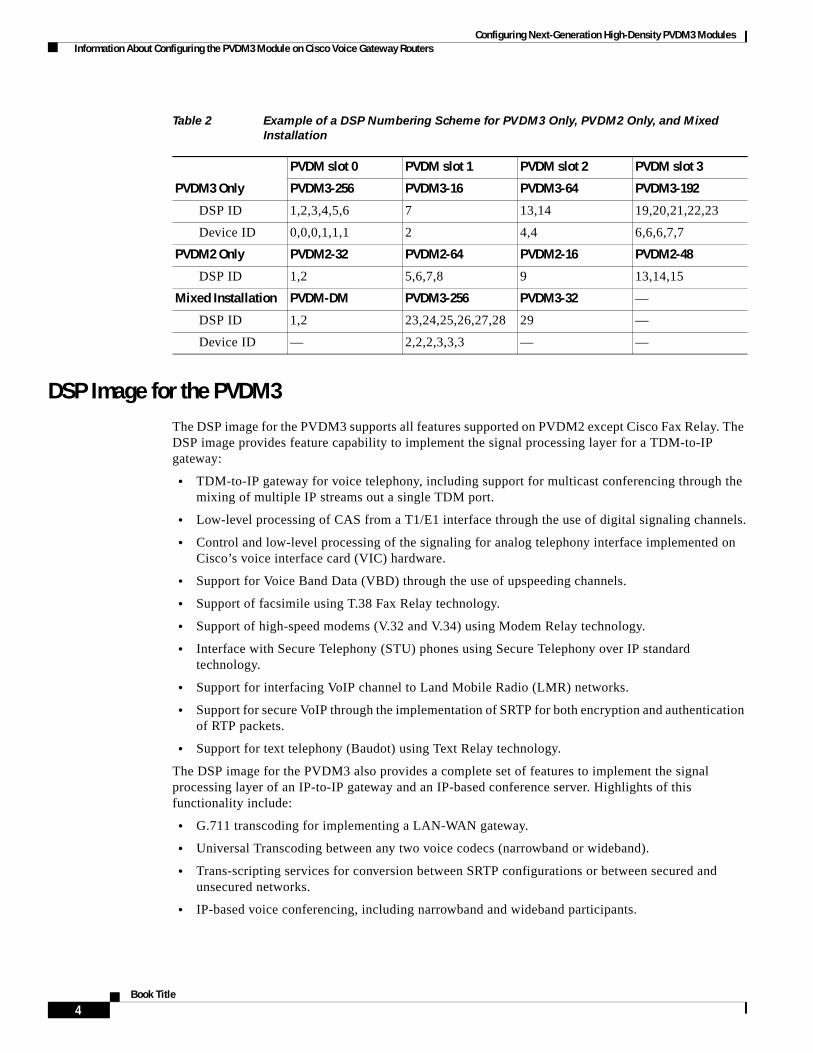
Configuring Next-Generation High-Density PVDM3 Modules Information About Configuring the PVDM3 Module on Cisco Voice Gateway Routers
DSP Image for the PVDM3The DSP image for the PVDM3 supports all features supported on PVDM2 except Cisco Fax Relay. The DSP image provides feature capability to implement the signal processing layer for a TDM-to-IP gateway:
• TDM-to-IP gateway for voice telephony, including support for multicast conferencing through the mixing of multiple IP streams out a single TDM port.
• Low-level processing of CAS from a T1/E1 interface through the use of digital signaling channels.
• Control and low-level processing of the signaling for analog telephony interface implemented on Cisco’s voice interface card (VIC) hardware.
• Support for Voice Band Data (VBD) through the use of upspeeding channels.
• Support of facsimile using T.38 Fax Relay technology.
• Support of high-speed modems (V.32 and V.34) using Modem Relay technology.
• Interface with Secure Telephony (STU) phones using Secure Telephony over IP standard technology.
• Support for interfacing VoIP channel to Land Mobile Radio (LMR) networks.
• Support for secure VoIP through the implementation of SRTP for both encryption and authentication of RTP packets.
• Support for text telephony (Baudot) using Text Relay technology.
The DSP image for the PVDM3 also provides a complete set of features to implement the signal processing layer of an IP-to-IP gateway and an IP-based conference server. Highlights of this functionality include:
• G.711 transcoding for implementing a LAN-WAN gateway.
• Universal Transcoding between any two voice codecs (narrowband or wideband).
• Trans-scripting services for conversion between SRTP configurations or between secured and unsecured networks.
• IP-based voice conferencing, including narrowband and wideband participants.
Table 2 Example of a DSP Numbering Scheme for PVDM3 Only, PVDM2 Only, and Mixed
Installation
PVDM3 Only
PVDM slot 0 PVDM slot 1 PVDM slot 2 PVDM slot 3
PVDM3-256 PVDM3-16 PVDM3-64 PVDM3-192
DSP ID 1,2,3,4,5,6 7 13,14 19,20,21,22,23
Device ID 0,0,0,1,1,1 2 4,4 6,6,6,7,7
PVDM2 Only PVDM2-32 PVDM2-64 PVDM2-16 PVDM2-48
DSP ID 1,2 5,6,7,8 9 13,14,15
Mixed Installation PVDM-DM PVDM3-256 PVDM3-32 —
DSP ID 1,2 23,24,25,26,27,28 29 —
Device ID — 2,2,2,3,3,3 — —
4Book Title

Configuring Next-Generation High-Density PVDM3 Modules Information About Configuring the PVDM3 Module on Cisco Voice Gateway Routers
DSP FarmsDSP Farm is enhanced to support increased transcoding and conference density. For DSPs on PVDM3 modules, existing resource allocation and management mechanisms are enhanced:
• For the PVDM3 DSP, participant-per-conference support is expanded to a maximum of 64. Note that this is supported only by low-complexity conference in Cisco IOS Release 15.0(1)M.
• Transcoding or conferencing channel allocation for a new call is modified to achieve load balancing. This is supported by the capability to select one channel from one DSP at a time.
DSP Farm ProfilesDSP-farm profiles are created to allocate DSP-farm resources. Under the profile, you select the service type (conference, transcode, or Media Termination Point [MTP]), associate an application, and specify service-specific parameters such as codecs and maximum number of sessions. A DSP-farm profile allows you to group DSP resources based on the service type. Applications associated with the profile, such as SCCP, can use the resources allocated under the profile. You can configure multiple profiles for the same service, each of which can register with one Cisco Unified Communications Manager group. The profile ID and service type uniquely identify a profile, allowing the profile to uniquely map to a Cisco Unified Communications Manager group that contains a single pool of Cisco Unified Communications Manager servers.
ConferencingVoice conferencing involves adding several parties to a phone conversation. In a traditional circuit-switched voice network, all voice traffic passes through a central device such as a PBX. Conference services are provided within this central device. In contrast, IP phones normally send voice signals directly between phones, without the need to go through a central device. Conference services, however, require a network-based conference bridge.
In an IP telephony network using Cisco Unified Communications Manager, the Conferencing and Transcoding for Voice Gateway Routers feature provides the conference-bridging service. Cisco Unified Communications Manager uses a DSP farm to mix voice streams from multiple participants into a single conference-call stream. The mixed stream is played out to all conference attendees, minus the voice of the receiving attendee.
The Ad Hoc and Meet Me conferencing features are supported (a conference can be either of these types):
• Ad Hoc—The person controlling the conference presses the telephone conference button and adds callers one by one.
• Meet Me—Participants call in to a central number and are joined in a single conference.
Participants whose end devices use different codec types are joined in a single conference; no additional transcoding resource is needed.
5Book Title

Configuring Next-Generation High-Density PVDM3 Modules Information About Configuring the PVDM3 Module on Cisco Voice Gateway Routers
Broadcast Fast Busy Tone for DSP OversubscriptionThere should always be a dial tone when a telephone is lifted. However, when DSP oversubscription occurs, and a caller goes off-hook, dead-air is received. With this feature, the caller receives a fast-busy tone instead of silence. This feature is not supported on application-controlled endpoints, Foreign Exchange Office (FXO) signaling endpoints, and BRI and Primary Rate Interface (PRI) endpoints.
The following lists the maximum number of different fast busy tone (specific to country) that can be supported by each PVDM type:
• PVDM3-16 1
• PVDM3-32 1
• PVDM3-64 2
• PVDM3-128 3
• PVDM3-192 3
• PVDM3-256 3
Prior to Cisco IOS Release 15.0(1)M, a new call attempt failed and dead silence occurred when DSPs were oversubscribed. When the PVDM3 is installed, a fast busy tone is broadcast to session application endpoints when DSP oversubscription occurs for both analog ports and digital ports, except PRI and BRI. FXO signaling and application controlled endpoints are not supported. This feature does not apply to insufficient DSP credits due to mid-call codec changes (while a call is already established).
Online Insertion and Removal
Cisco 3900 Series ISRs support only managed online insertion and removal. All voice ports and controllers should be shut down. Transcoding, conferencing, and MTP DSPfarm profiles need to be shut down in addition to the controller and voice port shutdown. Also, remove the DSP sharing (that is, DS0-group and DSPfarm sharing).
If the power efficiency management is configured on the module, the EnergyWise level must be set to 10 or online insertion and removal is not allowed.
Perform the following tasks for managed online insertion and removal on the Cisco 3900 Series ISRs:
1. Shut down the controller and voice ports.
2. Perform online insertion and removal.
3. Restart the controller and voice ports.
Shut down the controller and voice ports
Perform the steps detailed in this section to shut down the controller and voice ports
SUMMARY STEPS
1. enable
2. configure terminal
3. controller e1 slot/port
4. shutdown
5. exit
6. voice-port slot number/port
6Book Title

Configuring Next-Generation High-Density PVDM3 Modules Information About Configuring the PVDM3 Module on Cisco Voice Gateway Routers
7. shutdown
8. exit
DETAILED STEPS
Command or Action Purpose
Step 1 enable
Example:Router> enable
Enable privileged EXEC mode
• Enter your password if prompted.
Step 2 configure terminal
Example:Router# configure terminal
Enter global configuration mode.
Step 3 controller e1 slot/port
Example:Router(config)# controller e1 0/0/0
Enter config-controller mode.
Step 4 shutdown
Example:Router(config-controller)# shutdown
Administratively shuts down the controller port.
Step 5 exit
Example:Router(config-controller)# exit
Exit config-controller mode.
Step 6 voice-port slot number/port
Example:Router(config)# voice-port 0/0/0:1
Enter config-voiceport mode.
Step 7 shutdown
Example:Router(config-voiceport)# shutdown
Administratively shuts down the voice port.
Step 8 exit
Example:Router(config-voiceport)# exit
Exit config-voiceport mode.
Use the exit command till you are in privileged EXEC mode.
7Book Title

Configuring Next-Generation High-Density PVDM3 Modules Information About Configuring the PVDM3 Module on Cisco Voice Gateway Routers
Perform online insertion and removal
SUMMARY STEPS
1. hw-module sm slot oir-stop
2. Confirm that the board is ready for removal.The LED blinks for 3 seconds and turns off. After the LED is off, the board is ready for removal.
3. Insert the replacement board in the same slot or in an empty slot.
4. hw-module sm slot oir-start
DETAILED STEPS
Restart the controller and voice ports
SUMMARY STEPS
1. configure terminal
2. controller e1 slot/port
3. no shutdown
4. exit
5. voice-port slot number/port
6. no shutdown
7. exit
Command or Action Purpose
Step 1 hw-module sm slot oir-stop
Example:Router# hw-module sm 1 oir-stop
Shuts down the specified module to prepare it for removal.
Step 2 Wait until the LED signals that the board is ready for removal. The LED blinks for 3 seconds and turns off. After the LED is off, the board is ready for removal.
Step 3 Insert the replacement board in the same slot or in an empty slot.
Step 4 hw-module sm slot oir-start
Example:Router# hw-module sm 1 oir-start
Restores power to the module.
8Book Title

Configuring Next-Generation High-Density PVDM3 Modules Information About Configuring the PVDM3 Module on Cisco Voice Gateway Routers
DETAILED STEPS
Command or Action Purpose
Step 1 configure terminal
Example:Router# configure terminal
Enters global configuration mode.
Step 2 controller e1 slot/port
Example:Router(config)# controller e1 0/0/0
Enters config-controller mode.
Step 3 no shutdown
Example:Router(config-controller)# no shutdown
Restarts the controller port.
Step 4 exit
Example:Router(config-controller)# exit
Exits config-controller mode.
Step 5 voice-port slot number/port
Example:Router(config)# voice-port 0/0/0:1
Enters config-voiceport mode.
Step 6 no shutdown
Example:Router(config-voiceport)# no shutdown
Restarts the voice port.
Step 7 exit
Example:Router(config-voiceport)# exit
Exits config-voiceport mode.
9Book Title

Configuring Next-Generation High-Density PVDM3 Modules How to Verify and Troubleshoot the Functionality of the PVDM3 Cards on Cisco Voice Gateways
TDM Sharing/Pooling Configuration
Time-division multiplexing (TDM) sharing/pooling is only allowed among the same type of PVDMs. For example, if the motherboard has PVDM3 modules, and other voice cards have PVDM2 modules, the motherboard cannot share or pool DSP resources with other voice cards. If the motherboard has PVDM2 modules, and other voice cards also have PVDM2 modules, the existing CLI command will enable TDM sharing/pooling:
voice-card 0 dsp tdm pooling
In the case of mixed types of PVDMs existing in the router (for example, the motherboard has PVDM3, another voice card has PVDM2, and a third voice card has no PVDM), there is a new CLI command under the voice card CLI that allows the voice card to choose which type of PVDM to use for TDM sharing/pooling:
voice-card 2 dsp tdm pooling type [PVDM2 | PVDM3]
For more information about TDM sharing/pooling, see the documents listed in the “Additional References” section on page 22.
How to Verify and Troubleshoot the Functionality of the PVDM3 Cards on Cisco Voice Gateways
Use the following commands in global configuration mode to verify and troubleshoot the functionality of the PVDM2 and PVDM3 modules in your Cisco voice gateway.
SUMMARY STEPS
1. show platform hw-module-power
1. show voice call slot/port
2. show voice dsp group all
3. show voice dsp sorted-list
4. show voice dsp capabilities slot number dsp number
5. show voice dsp group slot number
6. show voice dsp statistics device
7. show voice dsp statistics tx-rx
8. show voice dsp statistics ack
9. debug voice dsp crash-dump
10Book Title

Configuring Next-Generation High-Density PVDM3 Modules How to Verify and Troubleshoot the Functionality of the PVDM3 Cards on Cisco Voice Gateways
DETAILED STEPS
Step 1 show platform hw-module-power
Note Effective with Cisco IOS Releases 15.1(1)T and 15.0.1M(2), the hw-module energywise level command is not available in Cisco IOS software. For more information, see the Cisco 3900 Series, 2900 Series, and 1900 Series Software Configuration Guide.
Use this command to display power settings of PVDM3 service modules, for example:
Router# show platform hw-module-power
PVDM: Slot 0/1 Levels supported 0x441 : SHUT FRUGAL FULL CURRENT level : 10 (FULL) Previous level : 10 (FULL) Transitions : Successful Unsuccessful SHUT : 0 0 FRUGAL : 0 0 FULL : 0 0
Slot 0/2 Levels supported 0x441 : SHUT FRUGAL FULL CURRENT level : 10 (FULL) Previous level : 0 (SHUT) Transitions : Successful Unsuccessful SHUT : 1 0 FRUGAL : 0 1 FULL : 1 0
Slot 0/3 Levels supported 0x441 : SHUT FRUGAL FULL CURRENT level : 10 (FULL) Previous level : 10 (FULL) Transitions : Successful Unsuccessful SHUT : 0 0 FRUGAL : 0 0 FULL : 0 0
Step 2 show voice call slot/port
Note If you are connected using a Telnet session, you must enter the terminal monitor command before the show voice call command to see console messages. This step is not necessary if you are connected to the console port.
Use this command to display statistics for voice calls on a specific slot and port, for example:
Router# show voice call 0/1/1:23
0/1/1:23 1 vtsp level 0 state = S_CONNECTcallid 0x0011 B01 state S_TSP_CONNECT clld 4085001112 cllg 40850011120/1/1:23 2 vtsp level 0 state = S_CONNECTcallid 0x0012 B02 state S_TSP_CONNECT clld 4085001112 cllg 40850011120/1/1:23 3 - - - 0/1/1:23 4 - - -
11Book Title

Configuring Next-Generation High-Density PVDM3 Modules How to Verify and Troubleshoot the Functionality of the PVDM3 Cards on Cisco Voice Gateways
0/1/1:23 5 - - - 0/1/1:23 6 - - - 0/1/1:23 7 - - - 0/1/1:23 8 - - - 0/1/1:23 9 - - - 0/1/1:23 10- - - 0/1/1:23 11- - - 0/1/1:23 12- - - 0/1/1:23 13- - - 0/1/1:23 14- - - 0/1/1:23 15- - - 0/1/1:23 16- - - 0/1/1:23 17- - - 0/1/1:23 18- - - 0/1/1:23 19- - - 0/1/1:23 20- - - 0/1/1:23 21- - - 0/1/1:23 22- - - 0/1/1:23 23- - -
Step 3 show voice dsp group all
Use this command to display information for each DSP group, for example:
Router# show voice dsp group all
DSP groups on slot 0:dsp 1: State: UP, firmware: 26.0.135 Max signal/voice channel: 43/43 Max credits: 645 num_of_sig_chnls_allocated: 35 Transcoding channels allocated: 0 Group: FLEX_GROUP_VOICE, complexity: FLEX Shared credits: 630, reserved credits: 0 Signaling channels allocated: 35 Voice channels allocated: 1 Credits used (rounded-up): 15 Voice channels: Ch01: voice port: 0/1/1:23.2, codec: g711alaw, credits allocated: 15 Slot: 0 Device idx: 0 PVDM Slot: 0 Dsp Type: SP2600
dsp 2: State: UP, firmware: 26.0.135 Max signal/voice channel: 43/43 Max credits: 645 num_of_sig_chnls_allocated: 0 Transcoding channels allocated: 0 Group: FLEX_GROUP_VOICE, complexity: FLEX Shared credits: 645, reserved credits: 0 Signaling channels allocated: 0 Voice channels allocated: 0 Credits used (rounded-up): 0 Slot: 0 Device idx: 0 PVDM Slot: 0 Dsp Type: SP2600
dsp 3: State: UP, firmware: 26.0.135 Max signal/voice channel: 42/43
12Book Title

Configuring Next-Generation High-Density PVDM3 Modules How to Verify and Troubleshoot the Functionality of the PVDM3 Cards on Cisco Voice Gateways
Max credits: 645 num_of_sig_chnls_allocated: 0 Transcoding channels allocated: 0 Group: FLEX_GROUP_VOICE, complexity: FLEX Shared credits: 645, reserved credits: 0 Signaling channels allocated: 0 Voice channels allocated: 0 Credits used (rounded-up): 0 Slot: 0 Device idx: 0 PVDM Slot: 0 Dsp Type: SP2600
dsp 4: State: UP, firmware: 26.0.135 Max signal/voice channel: 43/43 Max credits: 645 num_of_sig_chnls_allocated: 0 Transcoding channels allocated: 0 Group: FLEX_GROUP_VOICE, complexity: FLEX Shared credits: 645, reserved credits: 0 Signaling channels allocated: 0 Voice channels allocated: 0 Credits used (rounded-up): 0 Slot: 0 Device idx: 1 PVDM Slot: 0 Dsp Type: SP2600
dsp 5: State: UP, firmware: 26.0.135 Max signal/voice channel: 43/43 Max credits: 645 num_of_sig_chnls_allocated: 0 Transcoding channels allocated: 0 Group: FLEX_GROUP_VOICE, complexity: FLEX Shared credits: 645, reserved credits: 0 Signaling channels allocated: 0 Voice channels allocated: 0 Credits used (rounded-up): 0 Slot: 0 Device idx: 1 PVDM Slot: 0 Dsp Type: SP2600
dsp 6: State: UP, firmware: 26.0.135 Max signal/voice channel: 42/43 Max credits: 645 num_of_sig_chnls_allocated: 0 Transcoding channels allocated: 0 Group: FLEX_GROUP_VOICE, complexity: FLEX Shared credits: 645, reserved credits: 0 Signaling channels allocated: 0 Voice channels allocated: 0 Credits used (rounded-up): 0 Slot: 0 Device idx: 1 PVDM Slot: 0 Dsp Type: SP2600
13Book Title

Configuring Next-Generation High-Density PVDM3 Modules How to Verify and Troubleshoot the Functionality of the PVDM3 Cards on Cisco Voice Gateways
dsp 7: State: UP, firmware: 26.0.135 Max signal/voice channel: 32/32 Max credits: 480 num_of_sig_chnls_allocated: 0 Transcoding channels allocated: 0 Group: FLEX_GROUP_VOICE, complexity: FLEX Shared credits: 465, reserved credits: 0 Signaling channels allocated: 0 Voice channels allocated: 1 Credits used (rounded-up): 15 Voice channels: Ch01: voice port: 0/1/1:23.1, codec: g711alaw, credits allocated: 15 Slot: 0 Device idx: 0 PVDM Slot: 1 Dsp Type: SP2600
DSP groups on slot 1:
DSP groups on slot 2:dsp 1: State: UP, firmware: 26.0.133 Max signal/voice channel: 16/16 Max credits: 240 num_of_sig_chnls_allocated: 0 Transcoding channels allocated: 0 Group: FLEX_GROUP_VOICE, complexity: FLEX Shared credits: 240, reserved credits: 0 Signaling channels allocated: 0 Voice channels allocated: 0 Credits used (rounded-up): 0
dsp 2: State: UP, firmware: 26.0.133 Max signal/voice channel: 16/16 Max credits: 240 num_of_sig_chnls_allocated: 0 Transcoding channels allocated: 0 Group: FLEX_GROUP_VOICE, complexity: FLEX Shared credits: 240, reserved credits: 0 Signaling channels allocated: 0 Voice channels allocated: 0 Credits used (rounded-up): 0
dsp 3: State: UP, firmware: 26.0.133 Max signal/voice channel: 16/16 Max credits: 240 num_of_sig_chnls_allocated: 0 Transcoding channels allocated: 0 Group: FLEX_GROUP_VOICE, complexity: FLEX Shared credits: 240, reserved credits: 0 Signaling channels allocated: 0 Voice channels allocated: 0 Credits used (rounded-up): 0
14Book Title
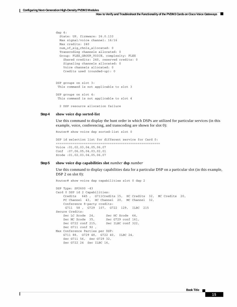
Configuring Next-Generation High-Density PVDM3 Modules How to Verify and Troubleshoot the Functionality of the PVDM3 Cards on Cisco Voice Gateways
dsp 4: State: UP, firmware: 26.0.133 Max signal/voice channel: 16/16 Max credits: 240 num_of_sig_chnls_allocated: 0 Transcoding channels allocated: 0 Group: FLEX_GROUP_VOICE, complexity: FLEX Shared credits: 240, reserved credits: 0 Signaling channels allocated: 0 Voice channels allocated: 0 Credits used (rounded-up): 0
DSP groups on slot 3: This command is not applicable to slot 3
DSP groups on slot 4: This command is not applicable to slot 4
2 DSP resource allocation failure
Step 4 show voice dsp sorted-list
Use this command to display the hunt order in which DSPs are utilized for particular services (in this example, voice, conferencing, and transcoding are shown for slot 0):
Router# show voice dsp sorted-list slot 0
DSP id selection list for different service for Card 0:========================================================Voice :01,02,03,04,05,06,07Conf :07,06,05,04,03,02,01Xcode :01,02,03,04,05,06,07
Step 5 show voice dsp capabilities slot number dsp number
Use this command to display capabilities data for a particular DSP on a particular slot (in this example, DSP 2 on slot 0):
Router# show voice dsp capabilities slot 0 dsp 2
DSP Type: SP2600 -43 Card 0 DSP id 2 Capabilities: Credits 645 , G711Credits 15, HC Credits 32, MC Credits 20, FC Channel 43, HC Channel 20, MC Channel 32, Conference 8-party credits: G711 58 , G729 107, G722 129, ILBC 215Secure Credits: Sec LC Xcode 24, Sec HC Xcode 64, Sec MC Xcode 35, Sec G729 conf 161, Sec G722 conf 215, Sec ILBC conf 322, Sec G711 conf 92 ,Max Conference Parties per DSP: G711 88, G729 48, G722 40, ILBC 24, Sec G711 56, Sec G729 32, Sec G722 24 Sec ILBC 16,
15Book Title

Configuring Next-Generation High-Density PVDM3 Modules How to Verify and Troubleshoot the Functionality of the PVDM3 Cards on Cisco Voice Gateways
Voice Channels: g711perdsp = 43, g726perdsp = 32, g729perdsp = 20, g729aperdsp = 32, g723perdsp = 20, g728perdsp = 20, g723perdsp = 20, gsmperdsp = 32, gsmefrperdsp = 20, gsmamrnbperdsp = 20, ilbcperdsp = 20, modemrelayperdsp = 20 g72264Perdsp = 32, h324perdsp = 20, m_f_thruperdsp = 43, faxrelayperdsp = 32, maxchperdsp = 43, minchperdsp = 20, srtp_maxchperdsp = 27, srtp_minchperdsp = 14, faxrelay_srtp_perdsp = 14, g711_srtp_perdsp = 27, g729_srtp_perdsp = 14, g729a_srtp_perdsp = 24,
Step 6 show voice dsp group slot number
Use this command to display the current status or selective statistics of DSP voice channels for a specific DSP group. For example:
Router# show voice dsp group slot 0dsp 1: State: UP, firmware: 8.4.0 Max signal/voice channel: 16/16 Max credits: 240 Group: FLEX_GROUP_VOICE, complexity: FLEX Shared credits: 240, reserved credits: 0 Signaling channels allocated: 0 Voice channels allocated: 0 Credits used: 0 Oversubscription: can either be an indicator or a counter DSP type: SP260x
Step 7 show voice dsp statistics device
Use this command to display DSP voice statistics for the device:
Router# show voice dsp statistics device
DEVICE DSP CURR AI/RST/WDT ACK MAC TX/RX PACK KEEPALIVEID ID STATE COUNT FAIL ADDRESS COUNT TX/RX/SKP======= === ===== ========= ===== ============= ================= =============0/0/0 1 1 0/0/0 0 00fa.ce25.0000 51645919/37972871 29875/29875/00/0/0 2 1 0/0/0 0 00fa.ce25.0000 51645919/37972871 29875/29875/00/0/0 3 1 0/0/0 0 00fa.ce25.0000 51645919/37972871 29875/29875/00/0/1 4 1 0/0/0 0 00fa.ce25.0001 28355309/20859980 29875/29875/00/0/1 5 1 0/0/0 0 00fa.ce25.0001 28355309/20859980 29875/29875/00/0/1 6 1 0/0/0 0 00fa.ce25.0001 28355309/20859980 29875/29875/0
Step 8 show voice dsp statistics tx-rx
Use this command to display transmitted and received packet counts for the device:
Router# show voice dsp statistics tx-rx
Device and Port Statistics: PVDM-0------------------------------------8903 input packets at port, 15374 output packets at portDevice 0: 6853 packets from device, 11793 packets to device 0 Ctrl & 0 Media out of sequence packets, 0 packets drop0 input error packets, 0 output error packets 0 resource errors packets, 0 gaints vlan id: 2
16Book Title
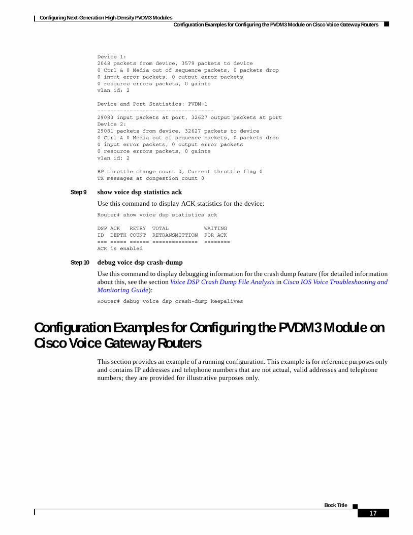
Configuring Next-Generation High-Density PVDM3 Modules Configuration Examples for Configuring the PVDM3 Module on Cisco Voice Gateway Routers
Device 1: 2048 packets from device, 3579 packets to device 0 Ctrl & 0 Media out of sequence packets, 0 packets drop0 input error packets, 0 output error packets 0 resource errors packets, 0 gaints vlan id: 2
Device and Port Statistics: PVDM-1------------------------------------29083 input packets at port, 32627 output packets at portDevice 2: 29081 packets from device, 32627 packets to device 0 Ctrl & 0 Media out of sequence packets, 0 packets drop0 input error packets, 0 output error packets 0 resource errors packets, 0 gaints vlan id: 2
BP throttle change count 0, Current throttle flag 0TX messages at congestion count 0
Step 9 show voice dsp statistics ack
Use this command to display ACK statistics for the device:
Router# show voice dsp statistics ack
DSP ACK RETRY TOTAL WAITING ID DEPTH COUNT RETRANSMITTION FOR ACK=== ===== ====== ============== ========ACK is enabled
Step 10 debug voice dsp crash-dump
Use this command to display debugging information for the crash dump feature (for detailed information about this, see the section Voice DSP Crash Dump File Analysis in Cisco IOS Voice Troubleshooting and Monitoring Guide):
Router# debug voice dsp crash-dump keepalives
Configuration Examples for Configuring the PVDM3 Module on Cisco Voice Gateway Routers
This section provides an example of a running configuration. This example is for reference purposes only and contains IP addresses and telephone numbers that are not actual, valid addresses and telephone numbers; they are provided for illustrative purposes only.
17Book Title

Configuring Next-Generation High-Density PVDM3 Modules Configuration Examples for Configuring the PVDM3 Module on Cisco Voice Gateway Routers
show running-config: ExampleRouter# show running-configBuilding configuration...
! voice-card 0:! Mixed PVDM3 and PVDM2 C5510 DSP cards detected.! Mixed DSP types in this slot is an unsupported configuration.! PVDM2 C5510 DSP cards have been disabled.
Current configuration : 3726 bytes!version 12.4no service padservice timestamps debug datetime msecservice timestamps log datetime msecno service password-encryption!hostname Router!boot-start-markerboot-end-marker!card type t1 0 0card type t1 2 0card type t1 2 1logging message-counter sysloglogging buffered 10000000!no aaa new-modelclock timezone PST 8no network-clock-participate slot 2 network-clock-participate wic 0 network-clock-select 1 T1 0/0/1!no ipv6 cefip source-routeip cef!!!!ip host hostname 223.255.254.254 255.255.255.255ntp update-calendarntp server 10.1.32.153ntp peer 10.1.32.153multilink bundle-name authenticated!!!!isdn switch-type primary-ni!!!voice-card 0 dsp services dspfarm!voice-card 2!!!
18Book Title
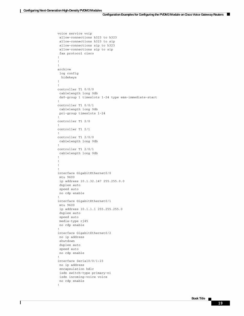
Configuring Next-Generation High-Density PVDM3 Modules Configuration Examples for Configuring the PVDM3 Module on Cisco Voice Gateway Routers
voice service voip allow-connections h323 to h323 allow-connections h323 to sip allow-connections sip to h323 allow-connections sip to sip fax protocol cisco !!!archive log config hidekeys!!controller T1 0/0/0 cablelength long 0db ds0-group 1 timeslots 1-24 type e&m-immediate-start!controller T1 0/0/1 cablelength long 0db pri-group timeslots 1-24!controller T1 2/0!controller T1 2/1!controller T1 2/0/0 cablelength long 0db!controller T1 2/0/1 cablelength long 0db!!!!interface GigabitEthernet0/0 mtu 9600 ip address 10.1.32.147 255.255.0.0 duplex auto speed auto no cdp enable!interface GigabitEthernet0/1 mtu 9600 ip address 10.1.1.1 255.255.255.0 duplex auto speed auto media-type rj45 no cdp enable!interface GigabitEthernet0/2 no ip address shutdown duplex auto speed auto no cdp enable!interface Serial0/0/1:23 no ip address encapsulation hdlc isdn switch-type primary-ni isdn incoming-voice voice no cdp enable!
19Book Title
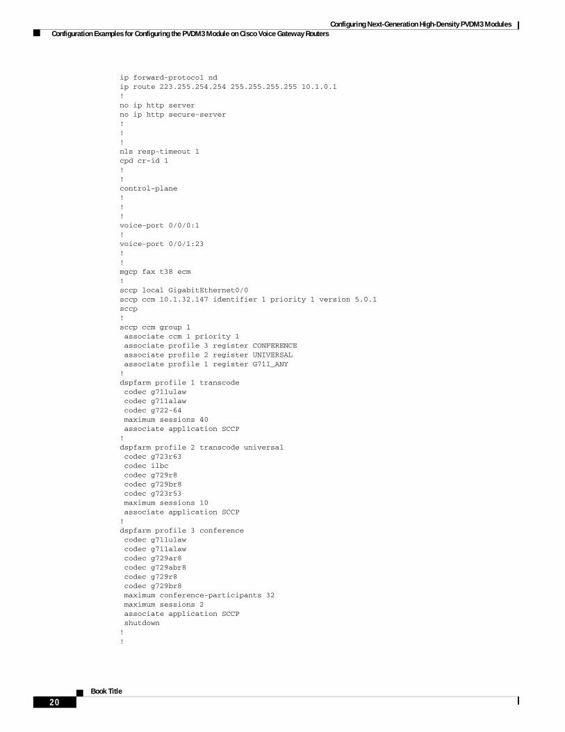
Configuring Next-Generation High-Density PVDM3 Modules Configuration Examples for Configuring the PVDM3 Module on Cisco Voice Gateway Routers
ip forward-protocol ndip route 223.255.254.254 255.255.255.255 10.1.0.1!no ip http serverno ip http secure-server!!!nls resp-timeout 1cpd cr-id 1!!control-plane!!!voice-port 0/0/0:1!voice-port 0/0/1:23!!mgcp fax t38 ecm!sccp local GigabitEthernet0/0sccp ccm 10.1.32.147 identifier 1 priority 1 version 5.0.1 sccp!sccp ccm group 1 associate ccm 1 priority 1 associate profile 3 register CONFERENCE associate profile 2 register UNIVERSAL associate profile 1 register G711_ANY!dspfarm profile 1 transcode codec g711ulaw codec g711alaw codec g722-64 maximum sessions 40 associate application SCCP!dspfarm profile 2 transcode universal codec g723r63 codec ilbc codec g729r8 codec g729br8 codec g723r53 maximum sessions 10 associate application SCCP!dspfarm profile 3 conference codec g711ulaw codec g711alaw codec g729ar8 codec g729abr8 codec g729r8 codec g729br8 maximum conference-participants 32 maximum sessions 2 associate application SCCP shutdown!!
20Book Title
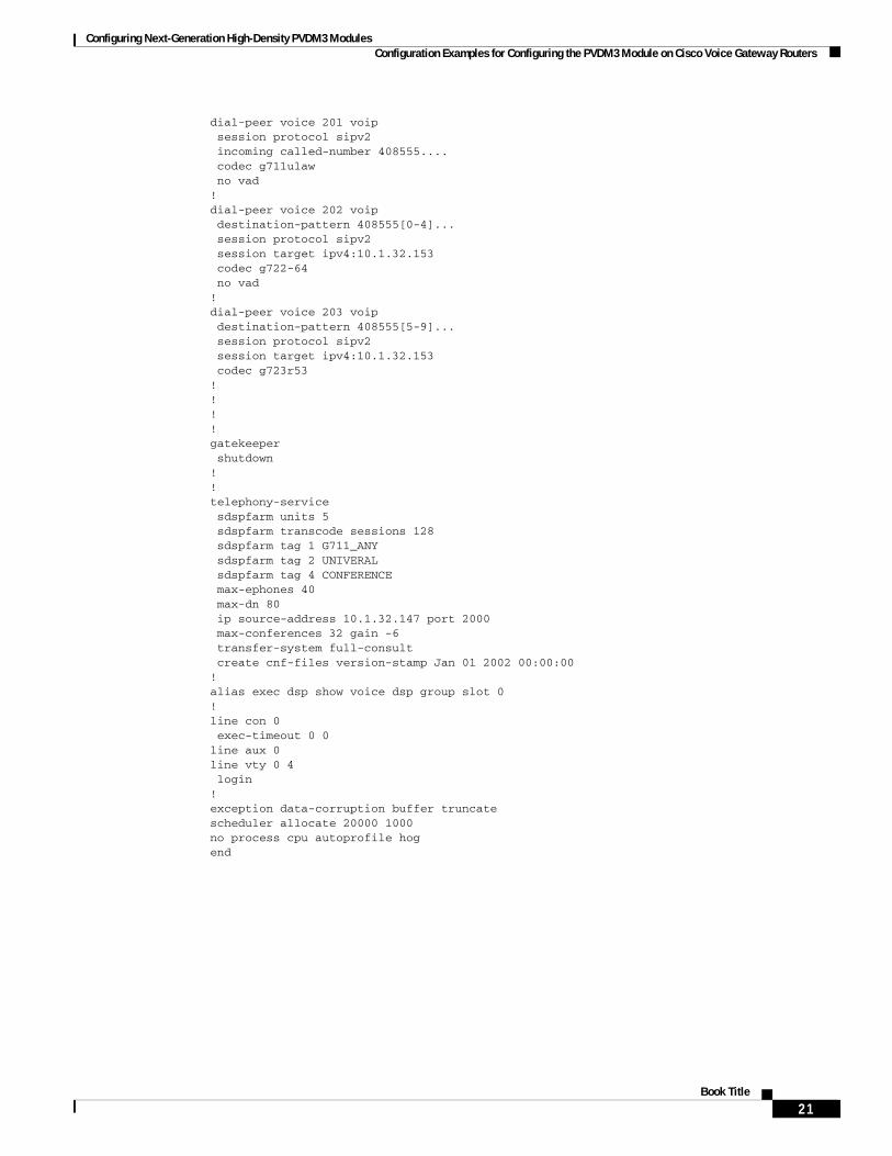
Configuring Next-Generation High-Density PVDM3 Modules Configuration Examples for Configuring the PVDM3 Module on Cisco Voice Gateway Routers
dial-peer voice 201 voip session protocol sipv2 incoming called-number 408555.... codec g711ulaw no vad!dial-peer voice 202 voip destination-pattern 408555[0-4]... session protocol sipv2 session target ipv4:10.1.32.153 codec g722-64 no vad!dial-peer voice 203 voip destination-pattern 408555[5-9]... session protocol sipv2 session target ipv4:10.1.32.153 codec g723r53!!!!gatekeeper shutdown!!telephony-service sdspfarm units 5 sdspfarm transcode sessions 128 sdspfarm tag 1 G711_ANY sdspfarm tag 2 UNIVERAL sdspfarm tag 4 CONFERENCE max-ephones 40 max-dn 80 ip source-address 10.1.32.147 port 2000 max-conferences 32 gain -6 transfer-system full-consult create cnf-files version-stamp Jan 01 2002 00:00:00!alias exec dsp show voice dsp group slot 0!line con 0 exec-timeout 0 0line aux 0line vty 0 4 login!exception data-corruption buffer truncatescheduler allocate 20000 1000no process cpu autoprofile hogend
21Book Title
Configuring Next-Generation High-Density PVDM3 Modules Additional References
Additional ReferencesThe following sections provide references related to the PVDM3 on Cisco Gateway Routers feature.
Related Documents
Standards
MIBs
RFCs
Related Topic Document Title
Comprehensive command reference information for Cisco IOS voice commands.
Cisco IOS Voice Command Reference
Configuration information for Cisco Voice Gateway Routers that are configured for Cisco Unified Communications Manager.
Cisco Unified Communications Manager and Cisco IOS Interoperability Guide
Complete hardware installation instructions for installing the PVDM3.
Cisco 2900 Series and 3900 Series Integrated Services Routers Hardware Installation Guide
Standard Title
None —
MIB MIBs Link
CISCO-DSP-MGMT-MIB To locate and download MIBs for selected platforms, Cisco IOS releases, and feature sets, use Cisco MIB Locator found at:
http://www.cisco.com/go/mibs
RFC Title
None —
22Book Title

Configuring Next-Generation High-Density PVDM3 Modules Feature Information for Configuring the PVDM3 Module on Cisco Voice Gateway Routers
Technical Assistance
Feature Information for Configuring the PVDM3 Module on Cisco Voice Gateway Routers
Table 3 lists the release history for this feature.
Not all commands may be available in your Cisco IOS software release. For release information about a specific command, see the command reference documentation.
Use Cisco Feature Navigator to find information about platform support and software image support. Cisco Feature Navigator enables you to determine which Cisco IOS and Catalyst OS software images support a specific software release, feature set, or platform. To access Cisco Feature Navigator, go to http://www.cisco.com/go/cfn. An account at Cisco.com is not required.
Note Table 3 lists only the Cisco IOS software release that introduced support for a given feature in a given Cisco IOS software release train. Unless noted otherwise, subsequent releases of that Cisco IOS software release train also support that feature.
Description Link
The Cisco Support and Documentation website provides online resources to download documentation, software, and tools. Use these resources to install and configure the software and to troubleshoot and resolve technical issues with Cisco products and technologies. Access to most tools on the Cisco Support and Documentation website requires a Cisco.com user ID and password.
http://www.cisco.com/cisco/web/support/index.html
Table 3 Feature Information for Configuring the PVDM3 Module on Cisco Voice Gateway Routers
Feature Name Releases Feature Information
Configuring the PVDM3 Module on Cisco Voice Gateway Routers
15.0(1)M 15.1(1)T 15.1(4)M
The PVDM3 DSP1 modules support high-density audio applications on the Cisco voice gateways. These DSP modules provide resources for voice termination, voice compression algorithms, echo cancellation, conferencing and transcoding, and support for modems and fax calls.
In Release 15.0(1)M, this feature is supported only on the Cisco 2901, Cisco 2911, Cisco 2921, Cisco 2951, Cisco 3925, and Cisco 3945.
In Release 15.1(1)T, this feature is supported only on the Cisco 3925E and Cisco 3945E ISRs.
In Release 15.1(4)M, support was added for video conference and transcoding.
1. DSP = digital signal processor
23Book Title
Configuring Next-Generation High-Density PVDM3 Modules Glossary
GlossaryAGC—Automatic Gain Control.
BCN—Backward Congestion Notification.
CM—Connection manager (TDM).
COS—Class of service, 802.1p.
DA—Ethernet Destination Address.
DMA—Direct Memory Access.
DSA—Distributed Switch Architecture.
DSP—Digital Signal Processor.
DSPRM—DSP Resource Manager.
DTMF—Dual-tone multi-frequency.
ECAN—Echo Canceller.
EVSM—Extended Voice Service Module.
FC—Flex Complexity.
FPGA—Field-Programmable Gate Array.
HC—High Complexity.
HDLC—High-level Data Link Control Protocol.
HPI—Host Port Interface.
LC—Low Complexity.
MAC—Media Access Control.
MC—Medium Complexity.
McBSP—Multi-Channel Buffer Serial Port.
MTBF—Mean Time Between Failures.
MTP—Media Termination Point.
NTE—Named Telephone Events.
OIR—Online Insertion and Removal.
PCE—Packet Classification Engine.
PVDM3—Next generation Packet Voice Data Module.
PVDM2—PVDM hosting 5510 DSP.
QOS—Quality of Service.
REA—Ethernet Ready Announcement, like bootp message.
RI—Restart indication from DSP/Device.
RTP—Real-time Transport Protocol.
SA—Ethernet source address.
SGMII—Serial Gigabit Media Independent Interface.
SM—Service Module.
SRTP—Secure Real-time Transport Protocol.
24Book Title
Configuring Next-Generation High-Density PVDM3 Modules Glossary
TDM—Time Division Multiplexing.
UHPI—Universal Host Port Interface.
VIC—Voice Interface Card.
VLAN—Virtual LAN.
VNM—Voice Network Module.
VWIC—Voice/WAN Interface Card.
Cisco and the Cisco Logo are trademarks of Cisco Systems, Inc. and/or its affiliates in the U.S. and other countries. A listing of Cisco's trademarks can be found at www.cisco.com/go/trademarks. Third party trademarks mentioned are the property of their respective owners. The use of the word partner does not imply a partnership relationship between Cisco and any other company. (1005R)
Any Internet Protocol (IP) addresses and phone numbers used in this document are not intended to be actual addresses and phone numbers. Any examples, command display output, network topology diagrams, and other figures included in the document are shown for illustrative purposes only. Any use of actual IP addresses or phone numbers in illustrative content is unintentional and coincidental.
© 2009-2011 Cisco Systems, Inc. All rights reserved.
25Book Title

Configuring Next-Generation High-Density PVDM3 Modules Glossary
26Book Title
Configuring Multi-Gigabit Fabric Communication
Cisco 3900 series, 2900 series, and 1900 series ISRs use a multi-gigabit fabric (MGF) for the new modules and interface cards to inter-communicate on the router. Legacy modules that support Cisco High-Speed Intrachassis Module Interconnect (HIMI) also support the MGF. Next generation module drivers integrate with the MGF to perform port configurations, configure packet flow, and control traffic buffering. On the router-side, there are no user-configurable features on the MGF. All configurations are performed from the module, which may or may not lead to changes on the MGF.
Modules and interface cards inter-communicate using the MGF on the router with or without CPU involvement. Modules and interface cards that communicate without CPU involvement reduce load and increase performance on the router. Modules and interface cards that do not utilize the MGF communicate with the CPU using the PCI Express (PCIe) link.
The following sections describe module and interface card communication through the MGF:
• Restrictions for Module and Interface Card Communication, page 1
• Supported Slots, Modules, and Interface Cards, page 2
• Cisco High-Speed Intrachassis Module Interconnect (HIMI), page 3
• Viewing Platform Information, page 4
Restrictions for Module and Interface Card CommunicationCisco 1941W
The wireless LAN (WLAN) module is only supported on the Cisco 1941W ISR.
Maximum Number of Legacy Switch Modules
A maximum of two integrated switch modules are supported when a legacy module is present in the system. In this scenario, the two switch modules have to be externally stacked.
Americas Headquarters:Cisco Systems, Inc., 170 West Tasman Drive, San Jose, CA 95134-1706 USA

Configuring Multi-Gigabit Fabric Communication Supported Slots, Modules, and Interface Cards
Supported Slots, Modules, and Interface CardsThe following slots support communication through the MGF:
• Service module (SM)
• Enhanced high-speed WAN interface card (EHWIC)
• Internal service module (ISM)
The following modules and interface cards support communication through the MGF:
• Wireless LAN Module in the Cisco 1941W ISR, page 2
• Cisco Etherswitch Service Modules, page 2
Cisco 3900 series, 2900 series, and 1900 series integrated services routers support legacy interface cards and modules. Some modules will require an adapter. See your router’s hardware installation guide at Cisco.com for adapter installation information.
See the routers’s Product page at Cisco.com for a complete list of supported new and legacy modules.
Wireless LAN Module in the Cisco 1941W ISRWhen configured as an autonomous access point, the wireless LAN (WLAN) device serves as the connection point between wireless and wired networks or as the center point of a stand-alone wireless network. In large installations, wireless users within radio range of a device can roam throughout a facility while maintaining seamless and uninterrupted access to the network.
Cisco 1941W supports ISM-to-EHWIC communication with an integrated switch communicating through the MGF. In this scenario traffic goes from the WLAN, through the Multi-Gigabit Fabric’s CPU port, and out through a port on the front panel.
Cisco Etherswitch Service ModulesThe following Cisco EtherSwitch service modules provide Cisco modular access routers the ability to stack Cisco EtherSwitch service modules as Layer 2 switches using Cisco StackWise technology.
• NME-16ES-1G
• NME-16ES-1G-P
• NME-X-23ES-1G
• NME-X-23ES-1G-P
• NME-XD-48ES-2S-P
• NME-XD-24ES-1S-P
The Cisco EtherSwitch service modules are supported by either the IP base image (formerly known as standard multilayer image [SMI]) or the IP services image (formerly known as the enhanced multilayer image [EMI]).
The IP base image provides Layer 2+ features, including access control lists, quality of service (QoS), static routing, and the Routing Information Protocol (RIP). The IP services image provides a richer set of enterprise-class features, including Layer 2+ features and full Layer 3 routing (IP unicast routing, IP multicast routing, and fallback bridging). To distinguish it from the Layer 2+ static routing and RIP, the IP services image includes protocols such as the Enhanced Interior Gateway Routing Protocol (EIGRP) and the Open Shortest Path First (OSPF) Protocol.
2Cisco 3900 Series, 2900 Series, and 1900 Series Integrated Services Routers Software Configuration Guide

Configuring Multi-Gigabit Fabric Communication Cisco High-Speed Intrachassis Module Interconnect (HIMI)
Cisco 3900 series, 2900 series, and 1900 series integrated services routers support the following Cisco EtherSwitch service modules for SM-to-SM or SM-to-ISM communication.
• NME-16ES-1G
• NME-16ES-1G-P
• NME-X-23ES-1G
• NME-X-23ES-1G-P
• NME-XD-48ES-2S-P
• NME-XD-24ES-1S-P
See the Cisco EtherSwitch Feature Guide documentation at Cisco.com for configuration details, http://www.cisco.com/en/US/docs/ios/12_3t/12_3t14/feature/guide/miragenm.html#wp1787811.
Cisco High-Speed Intrachassis Module Interconnect (HIMI) Cisco 3900 series and Cisco 2900 series routers use Cisco High-Speed Intrachassis Module Interconnect (HIMI) to support SM-to-SM or SM-to-ISM communication through the MGF.
Use the connect connection-name module Module1 Channel-id1 module Module2 Channel-id2 command to establish a maximum of two HIMI connections on the Cisco 3900 series ISR routers and one HIMI connection on Cisco 2900 series and1900 series ISRs. Module 1 and Module 2 are the slot/port of the two modules. The Channel-id1 and Channel-id2 variables must always have a value of 0.
When two modules are configured in a HIMI connection, the modules cannot send traffic to any other module except its HIMI-dedicated partner.
See Cisco High-Speed Intrachassis Module Interconnect (HIMI) Configuration Guide at Cisco.com for detailed configuration instructions, http://www.cisco.com/en/US/docs/ios/12_4/12_4_mainline/srdesfm1.html.
Note See the module documentation to validate HIMI support.
Using HIMI for VLAN Traffic Flows
For HIMI configurations, the port-level VLAN memberships are ignored on the Multi-Gigabit Fabric (MGF). Use the connect connection-name module module1 vlan-id module module2 command to redirect VLAN traffic flows from SM-to-SM or SM-to-ISM connections on the MGF.
The following two modules, as well as others, support VLAN traffic redirection:
• Cisco Etherswitch service module
• Cisco Services Ready Engine internal service module (ISM-SRE)
Note See the module documentation to validate HIMI support.
3Cisco 3900 Series, 2900 Series, and 1900 Series Integrated Services Routers Software Configuration Guide
OL-21850-01
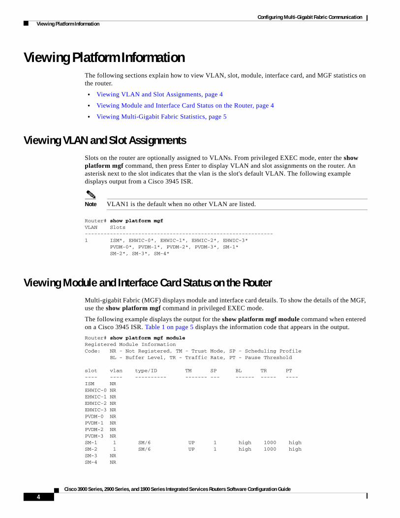
Configuring Multi-Gigabit Fabric Communication Viewing Platform Information
Viewing Platform InformationThe following sections explain how to view VLAN, slot, module, interface card, and MGF statistics on the router.
• Viewing VLAN and Slot Assignments, page 4
• Viewing Module and Interface Card Status on the Router, page 4
• Viewing Multi-Gigabit Fabric Statistics, page 5
Viewing VLAN and Slot AssignmentsSlots on the router are optionally assigned to VLANs. From privileged EXEC mode, enter the show platform mgf command, then press Enter to display VLAN and slot assignments on the router. An asterisk next to the slot indicates that the vlan is the slot's default VLAN. The following example displays output from a Cisco 3945 ISR.
Note VLAN1 is the default when no other VLAN are listed.
Router# show platform mgfVLAN Slots------------------------------------------------------------1 ISM*, EHWIC-0*, EHWIC-1*, EHWIC-2*, EHWIC-3* PVDM-0*, PVDM-1*, PVDM-2*, PVDM-3*, SM-1* SM-2*, SM-3*, SM-4*
Viewing Module and Interface Card Status on the RouterMulti-gigabit Fabric (MGF) displays module and interface card details. To show the details of the MGF, use the show platform mgf command in privileged EXEC mode.
The following example displays the output for the show platform mgf module command when entered on a Cisco 3945 ISR. Table 1 on page 5 displays the information code that appears in the output.
Router# show platform mgf moduleRegistered Module InformationCode: NR - Not Registered, TM - Trust Mode, SP - Scheduling Profile BL - Buffer Level, TR - Traffic Rate, PT - Pause Threshold
slot vlan type/ID TM SP BL TR PT---- ---- ---------- ------- --- ------ ----- ----ISM NREHWIC-0 NREHWIC-1 NREHWIC-2 NREHWIC-3 NRPVDM-0 NRPVDM-1 NRPVDM-2 NRPVDM-3 NRSM-1 1 SM/6 UP 1 high 1000 highSM-2 1 SM/6 UP 1 high 1000 highSM-3 NRSM-4 NR
4Cisco 3900 Series, 2900 Series, and 1900 Series Integrated Services Routers Software Configuration Guide
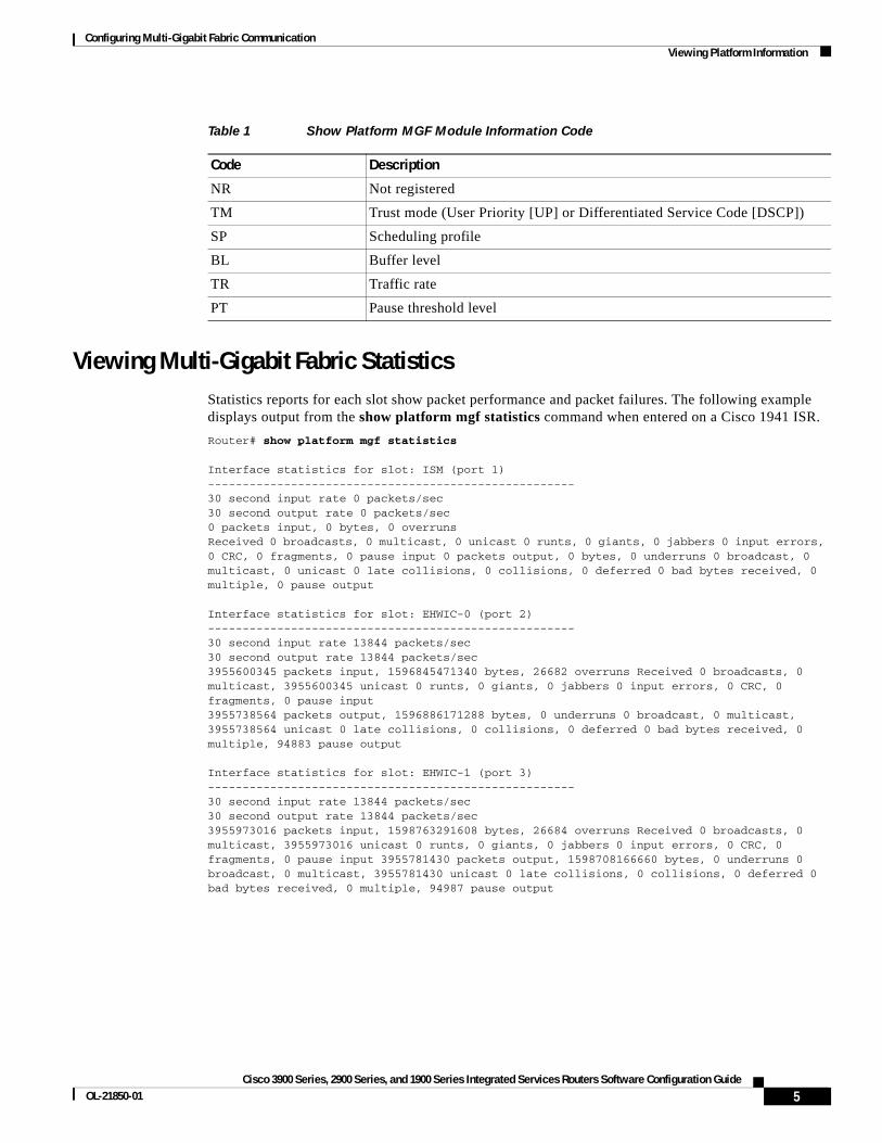
Configuring Multi-Gigabit Fabric Communication Viewing Platform Information
Viewing Multi-Gigabit Fabric StatisticsStatistics reports for each slot show packet performance and packet failures. The following example displays output from the show platform mgf statistics command when entered on a Cisco 1941 ISR.
Router# show platform mgf statistics
Interface statistics for slot: ISM (port 1)-----------------------------------------------------30 second input rate 0 packets/sec30 second output rate 0 packets/sec0 packets input, 0 bytes, 0 overrunsReceived 0 broadcasts, 0 multicast, 0 unicast 0 runts, 0 giants, 0 jabbers 0 input errors, 0 CRC, 0 fragments, 0 pause input 0 packets output, 0 bytes, 0 underruns 0 broadcast, 0 multicast, 0 unicast 0 late collisions, 0 collisions, 0 deferred 0 bad bytes received, 0 multiple, 0 pause output
Interface statistics for slot: EHWIC-0 (port 2)-----------------------------------------------------30 second input rate 13844 packets/sec30 second output rate 13844 packets/sec3955600345 packets input, 1596845471340 bytes, 26682 overruns Received 0 broadcasts, 0 multicast, 3955600345 unicast 0 runts, 0 giants, 0 jabbers 0 input errors, 0 CRC, 0 fragments, 0 pause input3955738564 packets output, 1596886171288 bytes, 0 underruns 0 broadcast, 0 multicast, 3955738564 unicast 0 late collisions, 0 collisions, 0 deferred 0 bad bytes received, 0 multiple, 94883 pause output
Interface statistics for slot: EHWIC-1 (port 3)-----------------------------------------------------30 second input rate 13844 packets/sec30 second output rate 13844 packets/sec3955973016 packets input, 1598763291608 bytes, 26684 overruns Received 0 broadcasts, 0 multicast, 3955973016 unicast 0 runts, 0 giants, 0 jabbers 0 input errors, 0 CRC, 0 fragments, 0 pause input 3955781430 packets output, 1598708166660 bytes, 0 underruns 0 broadcast, 0 multicast, 3955781430 unicast 0 late collisions, 0 collisions, 0 deferred 0 bad bytes received, 0 multiple, 94987 pause output
Table 1 Show Platform MGF Module Information Code
Code Description
NR Not registered
TM Trust mode (User Priority [UP] or Differentiated Service Code [DSCP])
SP Scheduling profile
BL Buffer level
TR Traffic rate
PT Pause threshold level
5Cisco 3900 Series, 2900 Series, and 1900 Series Integrated Services Routers Software Configuration Guide
OL-21850-01

Configuring Multi-Gigabit Fabric Communication Viewing Platform Information
Viewing Multi-Gigabit Fabric CPU Port StatisticsMulti-Gigabit Fabric’s CPU port statistics display details about the hardware status, data transmission rate, line type, protocols, and packets. The following example displays output for the show platform mgf statistics cpu command when entered on a Cisco 3945 ISR.
Router# show platform mgf statistics cpuBackplane-GigabitEthernet0/3 is up, line protocol is up Hardware is PQ3_TSEC, address is 001b.5428.d403 (bia 001b.5428.d403) MTU 9600 bytes, BW 1000000 Kbit/sec, DLY 10 usec, reliability 255/255, txload 1/255, rxload 1/255 Encapsulation ARPA, loopback not set Full-duplex, 1000Mb/s, media type is internal output flow-control is unsupported, input flow-control is unsupported ARP type: ARPA, ARP Timeout 04:00:00 Last input never, output never, output hang never Last clearing of "show interface" counters never Input queue: 0/75/0/0 (size/max/drops/flushes); Total output drops: 0 Queueing strategy: fifo Output queue: 0/40 (size/max) 5 minute input rate 0 bits/sec, 0 packets/sec 5 minute output rate 0 bits/sec, 0 packets/sec 0 packets input, 0 bytes, 0 no buffer Received 0 broadcasts, 0 runts, 0 giants, 0 throttles 0 input errors, 0 CRC, 0 frame, 0 overrun, 0 ignored 0 watchdog, 0 multicast, 0 pause input 0 input packets with dribble condition detected 0 packets output, 0 bytes, 0 underruns 0 output errors, 0 collisions, 0 interface resets 0 unknown protocol drops 0 babbles, 0 late collision, 0 deferred 0 lost carrier, 0 no carrier, 0 pause output 0 output buffer failures, 0 output buffers swapped out Interface statistics for CPU: (port 0)-----------------------------------------------------30 second input rate 0 packets/sec30 second output rate 0 packets/sec0 packets input, 0 bytes, 0 overrunsReceived 0 broadcasts, 0 multicast, 0 unicast 0 runts, 0 giants, 0 jabbers 0 input errors, 0 CRC, 0 fragments, 0 pause input 0 packets output, 0 bytes, 0 underruns 0 broadcast, 0 multicast, 0 unicast 0 late collisions, 0 collisions, 0 deferred 0 bad bytes received, 0 multiple, 0 pause output
6Cisco 3900 Series, 2900 Series, and 1900 Series Integrated Services Routers Software Configuration Guide

Configuring Multi-Gigabit Fabric Communication Viewing Platform Information
CCDE, CCENT, CCSI, Cisco Eos, Cisco HealthPresence, Cisco IronPort, the Cisco logo, Cisco Nurse Connect, Cisco Pulse, Cisco SensorBase, Cisco StackPower, Cisco StadiumVision, Cisco TelePresence, Cisco Unified Computing System, Cisco WebEx, DCE, Flip Channels, Flip for Good, Flip Mino, Flipshare (Design), Flip Ultra, Flip Video, Flip Video (Design), Instant Broadband, and Welcome to the Human Network are trademarks; Changing the Way We Work, Live, Play, and Learn, Cisco Capital, Cisco Capital (Design), Cisco:Financed (Stylized), Cisco Store, Flip Gift Card, and One Million Acts of Green are service marks; and Access Registrar, Aironet, AllTouch, AsyncOS, Bringing the Meeting To You, Catalyst, CCDA, CCDP, CCIE, CCIP, CCNA, CCNP, CCSP, CCVP, Cisco, the Cisco Certified Internetwork Expert logo, Cisco IOS, Cisco Lumin, Cisco Nexus, Cisco Press, Cisco Systems, Cisco Systems Capital, the Cisco Systems logo, Cisco Unity, Collaboration Without Limitation, Continuum, EtherFast, EtherSwitch, Event Center, Explorer, Follow Me Browsing, GainMaker, iLYNX, IOS, iPhone, IronPort, the IronPort logo, Laser Link, LightStream, Linksys, MeetingPlace, MeetingPlace Chime Sound, MGX, Networkers, Networking Academy, PCNow, PIX, PowerKEY, PowerPanels, PowerTV, PowerTV (Design), PowerVu, Prisma, ProConnect, ROSA, SenderBase, SMARTnet, Spectrum Expert, StackWise, WebEx, and the WebEx logo are registered trademarks of Cisco Systems, Inc. and/or its affiliates in the United States and certain other countries.
All other trademarks mentioned in this document or website are the property of their respective owners. The use of the word partner does not imply a partnership relationship between Cisco and any other company. (0910R)
Any Internet Protocol (IP) addresses used in this document are not intended to be actual addresses. Any examples, command display output, and figures included in the document are shown for illustrative purposes only. Any use of actual IP addresses in illustrative content is unintentional and coincidental. © 2009-2010 Cisco Systems, Inc. All rights reserved.
7Cisco 3900 Series, 2900 Series, and 1900 Series Integrated Services Routers Software Configuration Guide
OL-21850-01

Configuring Multi-Gigabit Fabric Communication Viewing Platform Information
8Cisco 3900 Series, 2900 Series, and 1900 Series Integrated Services Routers Software Configuration Guide

Upgrading the Cisco IOS Software
This module describes how to upgrade the Cisco Internet Operating System (IOS) software image on the following hardware:
• Cisco 3900 series ISRs
• Cisco 2900 series ISRs
• Cisco 1900 series ISRs
• Cisco 1941W Wireless Device
This module contains the following sections:
• Restrictions for Upgrading the System Image, page 1
• Information About Upgrading the System Image, page 2
• How to Upgrade the Cisco IOS Image, page 3
• How to Upgrade the IOS Image on the Access Point, page 23
• Additional References, page 26
Restrictions for Upgrading the System Image • Cisco 3900 series, 2900 series, and 1900 series integrated services routers (ISRs) download images
to new Advanced Capability CompactFlash (CF) memory cards. Legacy CF will not operate in Cisco 3900 series, 2900 series, and 1900 series ISRs. When legacy CF is inserted, the following error message appears:
WARNING: Unsupported compact flash detected. Use of this card during normal operation can impact and severely degrade performance of the system. Please use supported compact flash cards only.
• Slot0 is the default CF slot. CF in Slot0 stores system image, configuration, and data files. CF must be present in this slot for the router to boot and perform normal file operations.
• Cisco IOS images for the access point download images to the CF embedded on the access point.
Americas Headquarters:Cisco Systems, Inc., 170 West Tasman Drive, San Jose, CA 95134-1706 USA
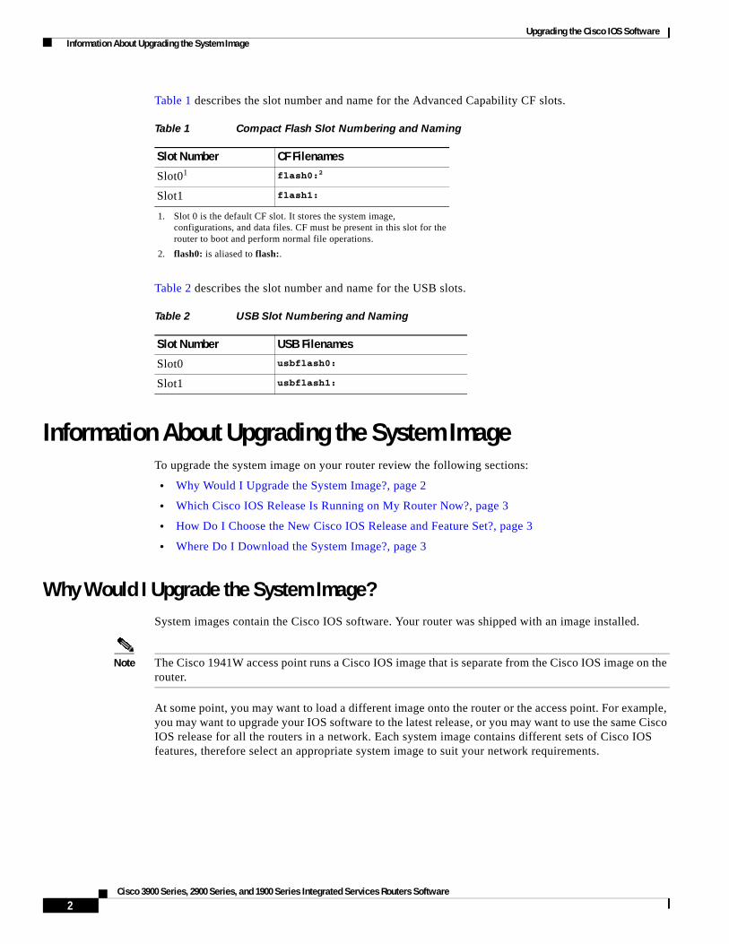
Upgrading the Cisco IOS Software Information About Upgrading the System Image
Table 1 describes the slot number and name for the Advanced Capability CF slots.
Table 2 describes the slot number and name for the USB slots.
Information About Upgrading the System ImageTo upgrade the system image on your router review the following sections:
• Why Would I Upgrade the System Image?, page 2
• Which Cisco IOS Release Is Running on My Router Now?, page 3
• How Do I Choose the New Cisco IOS Release and Feature Set?, page 3
• Where Do I Download the System Image?, page 3
Why Would I Upgrade the System Image?System images contain the Cisco IOS software. Your router was shipped with an image installed.
Note The Cisco 1941W access point runs a Cisco IOS image that is separate from the Cisco IOS image on the router.
At some point, you may want to load a different image onto the router or the access point. For example, you may want to upgrade your IOS software to the latest release, or you may want to use the same Cisco IOS release for all the routers in a network. Each system image contains different sets of Cisco IOS features, therefore select an appropriate system image to suit your network requirements.
Table 1 Compact Flash Slot Numbering and Naming
Slot Number CF Filenames
Slot01
1. Slot 0 is the default CF slot. It stores the system image, configurations, and data files. CF must be present in this slot for the router to boot and perform normal file operations.
flash0:2
2. flash0: is aliased to flash:.
Slot1 flash1:
Table 2 USB Slot Numbering and Naming
Slot Number USB Filenames
Slot0 usbflash0:
Slot1 usbflash1:
2Cisco 3900 Series, 2900 Series, and 1900 Series Integrated Services Routers Software

Upgrading the Cisco IOS Software How to Upgrade the Cisco IOS Image
Which Cisco IOS Release Is Running on My Router Now?To determine the Cisco IOS release that is currently running on your router, and the filename of the system image, enter the show version command in user EXEC or privileged EXEC mode.
How Do I Choose the New Cisco IOS Release and Feature Set?To determine which Cisco IOS releases and feature are supported on your platform, go to Cisco Feature Navigator at http://www.cisco.com/go/cfn. You must have an account at Cisco.com. If you do not have an account or have forgotten your username or password, click Cancel at the login dialog box and follow the instructions that appear.
Cisco 3900 series, 2900 series, and 1900 series ISRs support Cisco IOS software entitlement and enforcement. See Software Activation on Cisco Integrated Services Routers at Cisco.com for feature and package license information.
Where Do I Download the System Image?To download a system image you must have an account at Cisco.com to gain access to the following websites. If you do not have an account or have forgotten your username or password, click Cancel at the login dialog box, and follow the instructions that appear.
If you know the Cisco IOS release and feature set you want to download, go directly to http://www.cisco.com/kobayashi/sw-center/index.shtml.
For more information before selecting the Cisco IOS release and feature set, go to the Software Download Center at: http://www.cisco.com/public/sw-center/index.shtml.
For more information about Loading and Managing System images, go to http://www.cisco.com/en/US/docs/ios/fundamentals/configuration/guide/cf_system_images.html.
How to Upgrade the Cisco IOS ImageThis section provides information about upgrading the Cisco IOS image on the router.
• Saving Backup Copies of Your Old System Image and Configuration, page 4
• Ensuring Adequate DRAM for the New System Image, page 5
• Ensuring Adequate Flash Memory for the New System Image, page 7
• Copying the System Image into Flash Memory, page 10
• Loading the New System Image, page 16
• Saving Backup Copies of Your New System Image and Configuration, page 21
3Cisco 3900 Series, 2900 Series, and 1900 Series Integrated Services Routers Software
OL-21850-01

Upgrading the Cisco IOS Software How to Upgrade the Cisco IOS Image
Saving Backup Copies of Your Old System Image and ConfigurationTo avoid unexpected downtime in the event you encounter serious problems using a new system image or startup configuration, we recommend that you save backup copies of your current startup configuration file and Cisco IOS software system image file on a server.
For more detailed information, see the “Managing Configuration Files” chapter and the “Loading and Maintaining System Images” chapter of Cisco IOS Configuration Fundamentals Guide at: http://www.cisco.com/en/US/docs/ios/fundamentals/configuration/guide/12_4t/cf_12_4t_book.html.
To save backup copies of the startup configuration file and the system image file, complete the following steps.
SUMMARY STEPS
1. enable
2. copy nvram:startup-config {ftp: | rcp: | tftp:}
3. dir {flash0: | flash1:}
4. copy flash0: {ftp: | rcp: | tftp:}
DETAILED STEPS
Command or Action Purpose
Step 1 enable
Example:Router> enable
Enables privileged EXEC mode.
• Enter your password if prompted.
Step 2 copy nvram:startup-config {ftp: | rcp: | tftp:}
Example:Router# copy nvram:startup-config ftp:
Copies the startup configuration file to a server.
• The configuration file copy can serve as a backup copy.
• Enter the destination URL when prompted.
Step 3 dir flash0:
Example:Router# dir flash0:
Displays the layout and contents of a flash memory file system. flash0: is aliased onto flash:.
• Learn the name of the system image file.
Step 4 copy flash0: {ftp: | rcp: | tftp:}
Example:Router# copy flash0: ftp:
Copies a file from flash memory to a server.
• Copy the system image file to a server. This file can serve as a backup copy.
• Enter the flash memory partition number if prompted.
• Enter the filename and destination URL when prompted.
4Cisco 3900 Series, 2900 Series, and 1900 Series Integrated Services Routers Software
Upgrading the Cisco IOS Software How to Upgrade the Cisco IOS Image
Examples
The following examples show how to copy a startup configuration to a TFTP server and how to copy from flash memory to an FTP server.
Copying the Startup Configuration to a TFTP Server: Example
The following example shows the startup configuration being copied to a TFTP server:
Router# copy nvram:startup-config tftp:
Remote host[]? 192.0.0.1
Name of configuration file to write [rtr2-confg]? rtr2-config-b4upgrade Write file rtr2-confg-b4upgrade on host 192.0.0.1?[confirm] <cr> ![OK]
Copying from Flash Memory to a TFTP Server: Example
The following example uses the dir flash0: command in privileged EXEC mode to learn the name of the system image file and the copy flash0: tftp: command in privileged EXEC mode to copy the system image to a TFTP server. The router uses the default username and password.
Router# copy flash0: tftp:Source filename [running-config]?Address or name of remote host []? 192.0.0.1Destination filename [router-confg]? running-config983 bytes copied in 0.048 secs (20479 bytes/sec)
Router#Router# dir flash0:Directory of flash0:/
1 -rw- 48311224 Mar 2 1901 11:32:50 +00:00 c3900-universalk9-mz.SSA.XFR_20090407 2 -rw- 185667 Jan 27 2021 09:03:54 +00:00 crashinfo_20210127-090354 3 -rw- 983 Feb 14 2021 12:41:52 +00:00 running-config
260173824 bytes total (211668992 bytes free) Router#
Ensuring Adequate DRAM for the New System ImageThis section describes how to check whether your router has enough DRAM for upgrading to the new system image.
Prerequisites
Choose the Cisco IOS release and system image to which you want to upgrade. See the “Information About Upgrading the System Image” section on page 2.
5Cisco 3900 Series, 2900 Series, and 1900 Series Integrated Services Routers Software
OL-21850-01

Upgrading the Cisco IOS Software How to Upgrade the Cisco IOS Image
SUMMARY STEPS
1. Select the system image in the Cisco IOS Upgrade Planner at:
http://www.cisco.com/cgi-bin/Software/Iosplanner/Planner-tool/iosplanner.cgi.
2. Write down the minimum memory requirements for the image, as displayed in the File Download Information table.
3. show version
4. Add the memory sizes that are displayed in the show version command output to calculate your router’s DRAM size.
5. Compare the calculated DRAM size with the minimum memory requirements from Step 2.
a. If the DRAM is equal to or greater than the new system image’s minimum memory requirements, proceed to the “Ensuring Adequate Flash Memory for the New System Image” section on page 7.
b. If the DRAM is less than the new system image’s minimum flash requirements, you must upgrade your DRAM. See the hardware installation guide for your router.
DETAILED STEPS
Step 1 Select the system image in the Cisco IOS Upgrade Planner at:
http://www.cisco.com/cgi-bin/Software/Iosplanner/Planner-tool/iosplanner.cgi.
You must have an account at Cisco.com. If you do not have an account or have forgotten your username or password, click Cancel at the login dialog box and follow the instructions that appear.
Step 2 Write down the minimum memory requirements for the image, as displayed in the File Download Information table.
Step 3 Use the show version command to display the router processor and memory.
Step 4 Add the memory sizes to calculate the amount of DRAM in your router.
For example, if your memory sizes are 231424 KB and 30720 KB for a total of 262144 KB, it would be 256 MB of DRAM.
Tip To convert from kilobytes (KB) to megabytes (MB), divide the number of kilobytes by 1024.
Step 5 Compare the amount of DRAM in the router to the minimum memory requirements from Step 2.
a. If the DRAM is equal to or greater than the new system image’s minimum memory requirements, proceed to the “Ensuring Adequate Flash Memory for the New System Image” section on page 7.
b. If the DRAM is less than the new system image’s minimum memory requirements, you must upgrade your DRAM. See the hardware installation guide for your router.
6Cisco 3900 Series, 2900 Series, and 1900 Series Integrated Services Routers Software
Upgrading the Cisco IOS Software How to Upgrade the Cisco IOS Image
Ensuring Adequate Flash Memory for the New System ImageThis section describes how to check whether your router has enough flash memory to upgrade to the new system image and, if necessary, how to properly delete files in flash memory to make room for the new system image.
Cisco 3900 series, 2900 series, and 1900 series ISRs have two external CF slots and two USB slots. Use the secondary CF for overflow files, if required. Table 3 lists CF slot number, name, and size.
Table 4 lists the USB slot number, name, and size.
Prerequisites
In order to check whether your router has enough flash memory for a new system image, you need to obtain the image’s flash requirements from Cisco:
• Choose the Cisco IOS release and system image to which you want to upgrade. See the “Information About Upgrading the System Image” section on page 2.
• Select the system image in the Cisco IOS Upgrade Planner at:
http://www.cisco.com/cgi-bin/Software/Iosplanner/Planner-tool/iosplanner.cgi.
You must have an account at Cisco.com. If you do not have an account or have forgotten your username or password, click Cancel at the login dialog box and follow the instructions that appear.
From the File Download Information table, write down the minimum flash requirements for the image.
Table 3 Compact Flash Slot Number, Name, and Size
Slot Number CF Filename Size1
1. The maximum storage capacity for the CF in Slot0 and Slot1 is 4GB.
Slot02
2. Slot0 is the default CF slot. CF in Slot0 stores system image, configuration, and data files. CF must be present in this slot for the router to boot and perform normal file operations.
flash0: 256MB
Slot1 flash1: 0
Table 4 USB Slot Number, Name, and Size
Slot Number USB Filename Size1
1. The maximum storage capacity for the USB in Slot0 and Slot1 is 4GB.
Slot0 usbflash0: 64MB
Slot1 usbflash1: 0
7Cisco 3900 Series, 2900 Series, and 1900 Series Integrated Services Routers Software
OL-21850-01
Upgrading the Cisco IOS Software How to Upgrade the Cisco IOS Image
SUMMARY STEPS
1. enable
2. dir flash0:
3. From the displayed output of the dir flash0: command, compare the number of bytes available to the minimum flash requirements for the new system image.
a. If the available memory is equal to or greater than the new system image’s minimum flash requirements, proceed to the “Copying the System Image into Flash Memory” section on page 10.
b. If the available memory is less than the new system image’s minimum flash requirements, proceed to Step 4.
4. From the displayed output of the dir flash0: command, compare the number of bytes total to the size of the system image to which you want to upgrade.
a. If the total memory is less than the new system image’s minimum flash requirements, you must upgrade your compact flash memory card. See the hardware installation guide for your router.
b. If the total memory is equal to or greater than the new system image’s minimum flash requirements, proceed to Step 5.
5. dir /all flash0:
6. From the displayed output of the dir /all flash0: command, write down the names and directory locations of the files that you can delete.
7. (Optional) copy flash0: {tftp | rcp}
8. (Optional) Repeat Step 7 for each file that you identified in Step 6.
9. delete flash0:directory-path/filename
10. Repeat Step 9 for each file that you identified in Step 6.
11. dir flash0:[partition-number:]
12. From the displayed output of the dir flash0: command, compare the number of bytes available to the size of the system image to which you want to upgrade.
a. If the available memory is less than the new system image’s minimum flash requirements, then you must upgrade your compact flash memory card to a size that can accommodate both the existing files and the new system image. See the hardware installation guide for your router.
b. If the available memory is equal to or greater than the new system image’s minimum flash requirements, proceed to the “Copying the System Image into Flash Memory” section on page 10.
8Cisco 3900 Series, 2900 Series, and 1900 Series Integrated Services Routers Software

Upgrading the Cisco IOS Software How to Upgrade the Cisco IOS Image
DETAILED STEPS
Step 1 enable
Use this command to enter privileged EXEC mode. Enter your password if prompted. For example:
Router> enable Password:Router#
Step 2 dir flash0:
Use this command to display the layout and contents of flash memory:
Router# dir flash0:
Flash CompactFlash directory:File Length Name/status 1 6458208 c39xx.tmp [deleted] 2 6458208 c39xxmz[12916544 bytes used, 3139776 available, 16056320 total]15680K bytes of ATA CompactFlash (Read/Write)
Step 3 From the displayed output of the dir flash0: command, compare the number of bytes available to the minimum flash requirements for the new system image.
• If the available memory is equal to or greater than the new system image’s minimum flash requirements, proceed to the “Copying the System Image into Flash Memory” section on page 10.
• If the available memory is less than the new system image’s minimum flash requirements, proceed to Step 4.
Step 4 From the displayed output of the dir flash0: command, compare the number of bytes total to the size of the system image to which you want to upgrade.
• If the total memory is less than the new system image’s minimum flash requirements, you must upgrade your compact flash memory card. See the hardware installation guide for your router.
• If the total memory is equal to or greater than the new system image’s minimum flash requirements, proceed to Step 5.
Step 5 dir /all flash0:
Use this command to display a list of all files and directories in flash memory:
Router# dir /all flash0:
Directory of flash:/
3 -rw- 6458388 Mar 01 1993 00:00:58 c39xx.tmp 1580 -rw- 6462268 Mar 06 1993 06:14:02 c39xx-ata
63930368 bytes total (51007488 bytes free)
Step 6 From the displayed output of the dir /all flash0: command, write down the names and directory locations of the files that you can delete. If you cannot delete any files, you must upgrade your compact flash memory card. See the hardware installation guide for your router.
Note Do not delete the system image that the router already uses. If you are not sure which files can be safely deleted, either consult your network administrator or upgrade your compact flash memory card to a size that can accommodate both the existing files and the new system image. See the hardware installation guide for your router.
9Cisco 3900 Series, 2900 Series, and 1900 Series Integrated Services Routers Software
OL-21850-01

Upgrading the Cisco IOS Software How to Upgrade the Cisco IOS Image
Step 7 copy flash0:{tftp | rcp}
(Optional) Copy a file to a server before deleting the file from flash memory. When prompted, enter the filename and the server’s hostname or IP address:
Router# copy flash0: tftp
Step 8 (Optional) Repeat Step 7 for each file that you identified in Step 6.
Step 9 delete flash0:directory-path/filename
Use this command to delete a file in flash memory:
Router# delete flash0:c39xx.tmp
Delete filename [c39xx.tmp]? <cr> Delete flash0:c39xx.tmp? [confirm] <cr>
Step 10 Repeat Step 9 for each file that you identified in Step 6.
Step 11 dir flash0:
Use this command to display the layout and contents of flash memory:
Router# dir flash0:
Flash CompactFlash directory:File Length Name/status 1 6458208 c39xx.tmp [deleted] 2 6458208 c3xx-mz[12916544 bytes used, 3139776 available, 16056320 total]15680K bytes of ATA CompactFlash (Read/Write)
Step 12 From the displayed output of the dir flash0: command, compare the number of bytes available to the size of the system image to which you want to upgrade.
• If the available memory is less than the new system image’s minimum flash requirements, you must upgrade your compact flash memory card to a size that can accommodate both the existing files and the new system image. See the hardware installation guide for your router.
• If the available memory is equal to or greater than the new system image’s minimum flash requirements, proceed to the “Copying the System Image into Flash Memory” section on page 10.
What to Do Next
Proceed to the “Copying the System Image into Flash Memory” section on page 10.
Copying the System Image into Flash MemoryThis section describes how to copy the system image into the compact flash memory card for your router. Choose one of the following methods:
• Using TFTP or Remote Copy Protocol to Copy the System Image into Flash Memory, page 11
• Using the ROM Monitor to Copy the System Image over a Network, page 13
• Using a PC with a CompactFlash Card Reader to Copy the System Image into Flash Memory, page 15
10Cisco 3900 Series, 2900 Series, and 1900 Series Integrated Services Routers Software

Upgrading the Cisco IOS Software How to Upgrade the Cisco IOS Image
Using TFTP or Remote Copy Protocol to Copy the System Image into Flash Memory
This section describes how to use TFTP or Remote Copy Protocol (RCP) to upgrade the system image. This is the recommended and most common method of upgrading the system image.
Prerequisites
The following details the logistics of upgrading the system image.
• Install a TFTP server or an RCP server application on a TCP/IP-ready workstation or PC. Many third-party vendors provide free TFTP server software, which you can find by searching for “TFTP server” in a web search engine.
If you use TFTP:
– Configure the TFTP application to operate as a TFTP server, not a TFTP client.
– Specify the outbound file directory to which you will download and store the system image.
• Download the new Cisco IOS software image into the workstation or PC. See the “Where Do I Download the System Image?” section on page 3.
• Establish a console session to the router. We recommend that you connect your PC directly to the router console port. See the hardware installation guide for your router.
• Verify that the TFTP or RCP server has IP connectivity to the router. If you cannot successfully ping between the TFTP or RCP server and the router, do one of the following:
– Configure a default gateway on the router.
– Make sure that the server and the router each have an IP address in the same network or subnet. See the Determining IP Addresses: Frequently Asked Questions tech note.
Tip For more detailed information on how to perform the prerequisites, see the Software Installation and Upgrade Procedure tech note.
SUMMARY STEPS
1. enable
2. copy tftp flash0: or copy rcp flash0:
3. When prompted, enter the IP address of the TFTP or RCP server.
4. When prompted, enter the filename of the Cisco IOS software image to be installed.
5. When prompted, enter the filename as you want it to appear on the router.
6. If an error message appears that says, “Not enough space on device,” do one of the following, as appropriate:
• If you are certain that all the files in flash memory should be erased, enter y twice when prompted to erase flash before copying.
• If you are not certain that all files in flash memory should be erased, press Ctrl-Z and follow the instructions in the “Ensuring Adequate Flash Memory for the New System Image” section on page 7.
7. If the error message does not appear, enter no when prompted to erase the flash memory before copying.
11Cisco 3900 Series, 2900 Series, and 1900 Series Integrated Services Routers Software
OL-21850-01

Upgrading the Cisco IOS Software How to Upgrade the Cisco IOS Image
DETAILED STEPS
Step 1 enable
Use this command to enter privileged EXEC mode. Enter your password if prompted:
Router> enable Password: <password> Router#
Step 2 copy tftp flash0:
or
copy rcp flash0
Use one of these commands to copy a file from a server to flash memory:
Router# copy tftp flash0:
Step 3 When prompted, enter the IP address of the TFTP or RCP server:
Address or name of remote host []? 10.10.10.2
Step 4 When prompted, enter the filename of the Cisco IOS software image to be installed:
Source filename []? c2900-universalk9-mz.bin
Note The filename is case sensitive.
Step 5 When prompted, enter the filename as you want it to appear on the router. Typically, the same filename is entered as was used in Step 4:
Destination filename []? c2900-universalk9-mz.bin
Step 6 If an error message appears that says, “Not enough space on device,” do one of the following as appropriate:
• If you are certain that all the files in flash memory should be erased, enter y when prompted twice to confirm that flash memory will be erased before copying:
Accessing tftp://10.10.10.2/c2900-universalk9-mz.bin... Erase flash0: before copying? [confirm] y Erasing the flash filesystem will remove all files! Continue? [confirm] y Erasing device... eeeeeeeeeeeeeeeeeeeeeeeeeeeeeeeeeeeeeeeeeeeeeeeeeeeeee
• If you are not certain that all the files in flash memory should be erased, press Ctrl-Z and follow the instructions in the “Ensuring Adequate Flash Memory for the New System Image” section on page 7.
Step 7 If the error message does not appear, enter no when prompted to erase the flash memory before copying:
Accessing tftp://10.10.10.2/c2900-universalk9-mz.bin... Erase flash0: before copying? [confirm] no
Troubleshooting Tips
See the Common Problems in Installing Images Using TFTP or an RCP Server tech note.
12Cisco 3900 Series, 2900 Series, and 1900 Series Integrated Services Routers Software
Upgrading the Cisco IOS Software How to Upgrade the Cisco IOS Image
What to Do Next
Proceed to the “Loading the New System Image” section on page 16.
Using the ROM Monitor to Copy the System Image over a Network
This section describes how to download a Cisco IOS software image from a remote TFTP server to the router flash memory by using the tftpdnld ROM monitor command.
Caution Using the tftpdnld ROM monitor command may erase the system image, configuration, and data files. System image, configuration, and data files must be present on USB CF in slot0 for the router to boot and perform normal file operations.
Before you can enter the tftpdnld ROM monitor command, you must set the ROM monitor environment variables.
Prerequisites
Connect the TFTP server to a fixed network port on your router.
Restrictions
The LAN ports on network modules or interface cards are not active in ROM monitor mode. Therefore, only a fixed port on your router can be used for TFTP download. This can be either a fixed Ethernet port on the router or one of the Gigabit Ethernet ports on routers equipped with them.
Note You can use this command only to download files to the router. You cannot use tftpdnld to get files from the router.
SUMMARY STEPS
1. Enter ROM monitor mode
2. Set the IP_ADDRESS=ip_address configuration variable.
3. Set the IP_SUBNET_MASK=ip_address configuration variable.
4. Set the DEFAULT_GATEWAY=ip_address configuration variable.
5. Set the TFTP_SERVER=ip_address configuration variable.
6. Set the TFTP_FILE=[directory-path/]filename configuration variable.
7. (Optional) Set the GE_PORT=[0 | 1| 2 | 3] port number for download.
8. (Optional) Set the TFTP_MEDIA_TYPE=[0 | 1] copper or fiber.
9. (Optional) Set the TFTP_MACADDR= mac address of unit.
10. (Optional) Set the TFTP_VERBOSE= [0 | 1| 2] print setting variable.
11. (Optional) Set the TFTP_RETRY_COUNT=retry_times configuration variable.
12. (Optional) Set the TFTP_TIMEOUT=timeout of operation in seconds.
13. (Optional) Set the TFTP_ACK_RETRY=ack retry in seconds.
14. (Optional) Set the TFTP_CHECKSUM=[0 | 1] perform checksum test on image.
13Cisco 3900 Series, 2900 Series, and 1900 Series Integrated Services Routers Software
OL-21850-01

Upgrading the Cisco IOS Software How to Upgrade the Cisco IOS Image
15. (Optional) Set the TFTP_DESTINATION=[flash0: | flash1: | usbflash0: | usbflash1:] flash destination device for file.
16. (Optional) Set the GE_SPEED_MODE= speed configuration.
17. Use the set command to verify that you have set the variables correctly.
18. Use the tftpdnld [-r] command to download the image.
DETAILED STEPS
Step 1 Enter ROM monitor mode.
Step 2 Set the IP address of the router. For example:
rommon > IP_ADDRESS=172.16.23.32
Step 3 Set the IP subnet mask. For example:
rommon > IP_SUBNET_MASK=255.255.255.224
Step 4 Set the default gateway address. For example:
rommon > DEFAULT_GATEWAY=172.16.23.40
Step 5 Set the TFTP server IP address, which is the location from which the software will be downloaded:
rommon > TFTP_SERVER=172.16.23.33
Step 6 Set the name and directory location to which the image file will be downloaded onto the router. For example:
rommon > TFTP_FILE=archive/rel22/<image name>
Step 7 (Optional) Set the input port to use a Gigabit Ethernet port. Usage is GE_PORT=[0 | 1 | 2]. For example:
rommon > GE_PORT=0
Step 8 (Optional) Set the Ethernet media type. Usage is TFTP_ MEDIA_TYPE=[0 1], where Copper= 0 and Fiber=1:
rommon > TFTP_MEDIA_TYPE=1
Step 9 (Optional) Decide whether the router will perform a checksum test on the downloaded image. Usage is TFTP_CHECKSUM=[0 | 1], where 1=checksum test is performed (default) and 0=no checksum test. For example:
rommon > TFTP_CHECKSUM=0
Step 10 (Optional) Set the number of times that the router will attempt Address Resolution Protocol (ARP) and TFTP download. The default is 7 attempts. For example:
rommon > TFTP_RETRY_COUNT=10
Step 11 (Optional) Set the amount of time, in seconds, before the download process times out. The default is 2400 seconds (40 minutes). The following example shows 1800 seconds (30 minutes):
TFTP_TIMEOUT=1800
14Cisco 3900 Series, 2900 Series, and 1900 Series Integrated Services Routers Software
Upgrading the Cisco IOS Software How to Upgrade the Cisco IOS Image
Step 12 (Optional) Configure the print variable. Usage is TFTP_VERBOSE= [0 | 1 | 2], where print:
0= is quiet.
1= in progress.
2= verbose
Step 13 Use the set command to display the ROM monitor environment variables to verify that you have configured them correctly. For example:
rommon > set
Step 14 Download the system image, as specified by the ROM monitor environmental variables, using the tftpdnld [-r] command. Without the -r option, the command downloads the specified image and saves it in flash memory, deleting all existing data in all partitions in flash memory. Using the -r option downloads and boots the new software but does not save the software to flash memory.
rommon> tftpdnld [-r] A prompt is displayed:Do you wish to continue? y/n: [n]: y
Entering y confirms that you want to continue with the TFTP download.
What to Do Next
Proceed to the “Loading the New System Image” section on page 16.
Using a PC with a CompactFlash Card Reader to Copy the System Image into Flash Memory
Because the system image is stored on an external CompactFlash memory card, you can use a PC with a compact flash card reader to format the card and copy a new system image file onto the card. However, this upgrade method is not commonly used.
For more information about using flash memory cards, see Appendix B, “Using CompactFlash Memory Cards.”
Prerequisites
• Download the new Cisco IOS Software image to the PC. See the “Where Do I Download the System Image?” section on page 3.
• Locate the compact flash memory card slot on the router chassis. For help with locating the slot and instructions for removing and inserting the card, see the hardware installation guide for your router.
Caution Removing the compact flash memory card may disrupt the network because some software features use the compact flash memory card to store tables and other important data.
15Cisco 3900 Series, 2900 Series, and 1900 Series Integrated Services Routers Software
OL-21850-01

Upgrading the Cisco IOS Software How to Upgrade the Cisco IOS Image
DETAILED STEPS
Step 1 Remove the compact flash memory card from the router.
Step 2 Insert the card into the compact flash card reader on a PC.
Step 3 Use the PC to copy the system image file to the compact flash memory card.
Step 4 Remove the card from the compact flash card reader.
Step 5 Insert the compact flash memory card into the router.
What to Do Next
Proceed to the “Loading the New System Image” section on page 16.
Loading the New System ImageThis section describes how to load the new system image that you copied into flash memory. First, determine whether you are in ROM monitor mode or in the Cisco IOS CLI, then choose one of the following methods of loading the new system image:
• Loading the New System Image from the Cisco IOS Software, page 16
• Loading the New System Image from ROM Monitor Mode, page 19
Loading the New System Image from the Cisco IOS Software
To load the new system image from the Cisco IOS software, follow these steps.
SUMMARY STEPS
1. dir flash0:
2. configure terminal
3. no boot system
4. (Optional) boot system flash0: system-image-filename
5. (Optional) Repeat to specify the order in which the router should attempt to load any backup system images.
6. exit
7. show version
8. If the last digit in the configuration register is 0 or 1, proceed to Step 9. However, if the last digit in the configuration register is between 2 and F, proceed to Step 12.
9. configure terminal
10. config-register 0x2102
11. exit
12. copy run start
13. reload
16Cisco 3900 Series, 2900 Series, and 1900 Series Integrated Services Routers Software

Upgrading the Cisco IOS Software How to Upgrade the Cisco IOS Image
14. When prompted to save the system configuration, enter no.
15. When prompted to confirm the reload, enter y.
16. show version
DETAILED STEPS
Step 1 dir flash0:
Use this command to display a list of all files and directories in flash memory:
Router# dir flash0:
Directory of flash0:/
3 -rw- 6458388 Mar 01 1993 00:00:58 c38xx.tmp 1580 -rw- 6462268 Mar 06 1993 06:14:02 c38xx-ata
63930368 bytes total (51007488 bytes free)
Note Determine whether the new system image is the first file or the only file listed in the dir flash0: command output ( is not required if it is the first file or only file listed).
Step 2 configure terminal
Use this command to enter global configuration mode:
Router# configure terminal
Router(config)#
Step 3 no boot system
Use this command to delete all entries in the bootable image list, which specifies the order in which the router attempts to load the system images at the next system reload or power cycle:
Router(config)# no boot system
Step 4 If the new system image is the first file or the only file displayed in the dir flash0: command output, you do not need to perform the following step.
boot system flash0: system-image-filename
Use this command to load the new system image after the next system reload or power cycle. For example:
Router(config)# boot system flash0: c2900-universalk9-mz.bin
Step 5 (Optional) Repeat to specify the order in which the router should attempt to load any backup system images.
Step 6 exit
Use this command to exit global configuration mode:
Router(config)# exit Router#
17Cisco 3900 Series, 2900 Series, and 1900 Series Integrated Services Routers Software
OL-21850-01
Upgrading the Cisco IOS Software How to Upgrade the Cisco IOS Image
Step 7 show version
Use this command to display the configuration register setting:
Router# show version
Cisco Internetwork Operating System Software...Configuration register is 0x0
Router#
Step 8 If the last digit in the configuration register is 0 or 1, proceed to Step 9. However, if the last digit in the configuration register is between 2 and F, proceed to Step 12.
Step 9 configure terminal
Use this command to enter global configuration mode:
Router# configure terminal
Router(config)#
Step 10 config-register 0x2102
Use this command to set the configuration register so that, after the next system reload or power cycle, the router loads a system image from the boot system commands in the startup configuration file:
Router(config)# config-register 0x2102
Step 11 exit
Use this command to exit global configuration mode:
Router(config)# exit Router#
Step 12 copy run start
Use this command to copy the running configuration to the startup configuration:
Router# copy run start
Step 13 reload
Use this command to reload the operating system:
Router# reload
Step 14 When prompted to save the system configuration, enter no:
System configuration has been modified. Save? [yes/no]: no
18Cisco 3900 Series, 2900 Series, and 1900 Series Integrated Services Routers Software

Upgrading the Cisco IOS Software How to Upgrade the Cisco IOS Image
Step 15 When prompted to confirm the reload, enter y:
Proceed with reload? [confirm] y
Step 16 show version
Use this command to verify that the router loaded the proper system image:
Router# show version
00:22:25: %SYS-5-CONFIG_I: Configured from console by consoleCisco Internetwork Operating System Software ...System returned to ROM by reloadSystem image file is "flash0:c2900-universalk9-mz.bin"
What to Do Next
Proceed to the “Saving Backup Copies of Your New System Image and Configuration” section on page 21.
Loading the New System Image from ROM Monitor Mode
To load the new system image from ROM monitor mode, follow these steps.
SUMMARY STEPS
1. dir flash0:[partition-number:]
2. confreg 0x2102
3. boot flash0:[partition-number:]filename
4. After the system loads the new system image, press Return a few times to display the Cisco IOS command-line interface (CLI) prompt.
5. enable
6. configure terminal
7. no boot system
8. boot system flash0: new-system-image-filename
9. (Optional) Repeat to specify the order in which the router should attempt to load any backup system images.
10. exit
11. copy run start
19Cisco 3900 Series, 2900 Series, and 1900 Series Integrated Services Routers Software
OL-21850-01

Upgrading the Cisco IOS Software How to Upgrade the Cisco IOS Image
DETAILED STEPS
Step 1 dir flash0:[partition-number:]
Use this command to list files in flash memory:
rommon > dir flash0:
program load complete, entry point: 0x4000000, size: 0x18fa0Directory of flash0:
2 48296872 -rw- c3900-universalk9-mz.SPA
Note whether the new system image is the first file or the only file listed in the dir flash0: command output.
Step 2 confreg 0x2102
Use this command to set the configuration register so that, after the next system reload or power cycle, the router loads a system image from the boot system commands in the startup configuration file:
rommon > confreg 0x2102
Step 3 boot flash0:[partition-number:]filename
Use this command to force the router to load the new system image:
rommon > boot flash0:c2900-universalk9-mz.binT
Step 4 After the system loads the new system image, press Return a few times to display the Cisco IOS CLI prompt.
Step 5 enable
Use this command to enable privileged EXEC mode, and enter your password if prompted:
Router> enable Password: <password> Router#
Step 6 configure terminal
Use this command to enter global configuration mode:
Router# configure terminalRouter(config)#
Step 7 no boot system
Eliminate all entries in the bootable image list, which specifies the system image that the router loads at startup:
Router(config)# no boot system
Step 8 If the new system image is the first file or only the file displayed in the dir flash0: command output, this step is not required.
boot system flash0: new-system-image-filename
Use this command to load the new system image after the next system reload or power cycle:
Router(config)# boot system flash0: c2900-universalk9-mz.bin
Step 9 (Optional) Repeat to specify the order in which the router should attempt to load any backup system images.
20Cisco 3900 Series, 2900 Series, and 1900 Series Integrated Services Routers Software
Upgrading the Cisco IOS Software How to Upgrade the Cisco IOS Image
Step 10 exit
Use this command to exit global configuration mode:
Router(config)# exit Router#
Step 11 copy run start
Use this command to copy the running configuration to the startup configuration:
Router# copy run start
What to Do Next
Proceed to the “Saving Backup Copies of Your New System Image and Configuration” section on page 21.
Saving Backup Copies of Your New System Image and ConfigurationTo aid file recovery and to minimize downtime in the event of file corruption, we recommend that you save backup copies of the startup configuration file and the Cisco IOS software system image file on a server.
Tip Do not erase any existing backup copies of your configuration and system image that you saved before upgrading your system image. If you encounter serious problems using your new system image or startup configuration, you can quickly revert to the previous working configuration and system image.
For more detailed information, see the “Managing Configuration Files” chapter and the “Loading and Maintaining System Images” chapter of the Cisco IOS Configuration Fundamentals Configuration Guide at: http://www.cisco.com/en/US/docs/ios/fundamentals/configuration/guide/12_4/cf_12_4_book.html.
To save backup copies of the startup configuration file and the system image file, complete the following steps.
SUMMARY STEPS
1. enable
2. copy nvram:startup-config {ftp: | rcp: | tftp:}
3. dir flash0:
4. copy flash0: {ftp: | rcp: | tftp:}
21Cisco 3900 Series, 2900 Series, and 1900 Series Integrated Services Routers Software
OL-21850-01

Upgrading the Cisco IOS Software How to Upgrade the Cisco IOS Image
DETAILED STEPS
Examples
Copying the Startup Configuration to a TFTP Server: Example
The following example shows the startup configuration being copied to a TFTP server:
Router# copy nvram:startup-config tftp:
Remote host[]? 172.16.101.101
Name of configuration file to write [rtr2-confg]? <cr> Write file rtr2-confg on host 172.16.101.101?[confirm] <cr> ![OK]
Copying from Flash Memory to a TFTP Server: Example
The following example uses the dir flash0: privileged EXEC command to obtain the name of the system image file and the copy flash0: tftp: privileged EXEC command to copy the system image to a TFTP server. The router uses the default username and password.
Router# dir flash0:
System flash directory:File Length Name/status1 4137888 c2900-mz[4137952 bytes used, 12639264 available, 16777216 total]16384K bytes of processor board System flash (Read/Write)\
Command or Action Purpose
Step 1 enable
Example:Router> enable
Enables privileged EXEC mode.
• Enter your password if prompted.
Step 2 copy nvram:startup-config {ftp: | rcp: | tftp:}
Example:Router# copy nvram:startup-config ftp:
Copies the startup configuration file to a server.
• The configuration file copy serves as a backup copy.
• Enter the destination URL when prompted.
Step 3 dir flash0:
Example:Router# dir flash0:
Displays the layout and contents of a flash memory file system.
• Write down the name of the system image file.
Step 4 copy flash0: {ftp: | rcp: | tftp:}
Example:Router# copy flash0: ftp:
Copies a file from flash memory to a server.
• Copy the system image file to a server to serve as a backup copy.
• Enter the flash memory partition number if prompted.
• Enter the filename and destination URL when prompted.
22Cisco 3900 Series, 2900 Series, and 1900 Series Integrated Services Routers Software

Upgrading the Cisco IOS Software How to Upgrade the IOS Image on the Access Point
Router# copy flash0: tftp: IP address of remote host [255.255.255.255]? 192.0.0.1 filename to write on tftp host? c2900-universalk9-mz writing c2900-mz !!!!...successful ftp write.
How to Upgrade the IOS Image on the Access PointThis section describes how to upgrade the Cisco IOS image on the access point.
To upgrade the IOS image on the access point, establish connectivity between the access point and the download server by following these steps:
• Define the WAN Interface on the Router, page 23
• Secure an IP Address on the Access Point, page 24
• Confirm Connectivity and Settings, page 24
• Upgrading the IOS Image on the Access Point, page 25
Define the WAN Interface on the RouterTo define a WAN interface to connect to a TFTP network for image download, follow these steps, beginning in global configuration mode.
SUMMARY STEPS
1. interface gigabitethernet slot/port
2. ip address ip-address mask
3. no shutdown
4. exit
DETAILED STEPS
Command Purpose
Step 1 interface gigabitethernet slot/port
Example:Router(config)# interface gigabitethernet 0/0Router(config-if)#
Enters the configuration mode for a Gigabit Ethernet interface on the router.
Step 2 ip address ip-address mask
Example:Router(config-if)# ip address 192.168.12.2 255.255.255.0Router(config-if)#
Sets the IP address and subnet mask for the specified Gigabit Ethernet interface.
23Cisco 3900 Series, 2900 Series, and 1900 Series Integrated Services Routers Software
OL-21850-01

Upgrading the Cisco IOS Software How to Upgrade the IOS Image on the Access Point
Secure an IP Address on the Access PointTo secure an IP address on the access point so it can communicate with an external server where a Cisco IOS image is located, use the DHCP server functionality on the router. The host router provides the access point DHCP server functionality through the DHCP pool. The access point communicates with the external server and setup option 43 for the controller IP address in the DHCP pool configuration.
Example
The following example shows a dhcp pool configuration:
ip dhcp pool embedded-ap-poolnetwork 192.168.10.0 255.255.255.0dns-server 171.70.168.183default-router 192.168.10.1 int vlan1ip address 192.168.10.0 255.255.255.0
Confirm Connectivity and SettingsPerform the following steps to confirm connectivity.
1. Ping the external server from the router to confirm connectivity.
2. Enter the service-module wlan-ap 0 session command to establish a session into the access point. For instructions, see “Starting a Wireless Configuration Session” section on page 1.
3. Ping the external server from the access point to confirm connectivity.
The following example shows a sample router and access point configuration:
Example
interface Wlan-GigabitEthernet0/0!interface GigabitEthernet0/0 ip address dhcp duplex auto speed auto!interface wlan-ap0
Step 3 no shutdown
Example:Router(config-if)# no shutdownRouter(config-if)#
Enables the Gigabit Ethernet interface, changing its state from administratively down to administratively up.
Step 4 exit
Example:Router(config-if)# exitRouter(config)#
Exits configuration mode for the Gigabit Ethernet interface and returns to global configuration mode.
Command Purpose
24Cisco 3900 Series, 2900 Series, and 1900 Series Integrated Services Routers Software

Upgrading the Cisco IOS Software How to Upgrade the IOS Image on the Access Point
description Service module interface to manage the embedded AP ip address 10.0.0.1 255.0.0.0 arp timeout 0!interface GigabitEthernet0/1 no ip address shutdown duplex auto speed auto!interface Vlan1 ip address 192.168.10.1 255.255.255.0!ip forward-protocol ndip route 0.0.0.0 0.0.0.0 GigabitEthernet0/0!no ip http server
Upgrading the IOS Image on the Access PointFollow the image upgrade instructions at Cisco.com using the IOS CLI, http://www.cisco.com/en/US/docs/wireless/access_point/12.3_8_JA/configuration/guide/ s38mfw.html#wp1035609.
Note If the access point enters Bootloader mode, manually configure the IP address, default router, netmask, and default gateway to upgrade the IOS image.
Note The IP address must be assigned to the same subnet as the VLAN1 interface on the router. Here is an example configuration.
Example
ap: set
CONTROLLER_TYPE=0x05A4
DEFAULT_ROUTER=192.168.10.1
ENABLE_BREAK=yes
IOS_STATIC_DEFAULT_GATEWAY=192.168.10.1
IP_ADDR=192.168.10.2
MANUAL_BOOT=yes
NETMASK=255.255.255.0
PEP_PRODUCT_ID=AP801AGN-A-K9
PRODUCT_MODEL_NUM=AP801AGN-A-K9
TOP_ASSY_SERIAL_NUM=FHKTESTTEST
ap: copy tftp://223.255.254.254/saek/ap801-k9w7-tar.124-10b.JDA flash0: ap801-k9w7-tar.124-10b.JDA
25Cisco 3900 Series, 2900 Series, and 1900 Series Integrated Services Routers Software
OL-21850-01
Upgrading the Cisco IOS Software Additional References
Additional ReferencesThe following sections provide references related to upgrading the system image on your router.
Related Documents and Websites
Technical Assistance
Related Topic Document Title or Website
Matching Cisco IOS releases and features to hardware Cisco Feature Navigator
http://www.cisco.com/go/fn
Downloading system images
Displaying minimum DRAM and flash memory requirements
Cisco IOS Upgrade Planner
http://www.cisco.com/cgi-bin/Software/Iosplanner/Planner-tool/ iosplanner.cgi
Choosing and downloading system images Software Download Center
http://www.cisco.com/kobayashi/sw-center/index.shtml
Loading and maintaining system images http://www.cisco.com/en/US/docs/ios/fundamentals/configuration/guide/cf_system_images.html
Removing, inserting, and upgrading compact flash memory cards
Hardware installation guide for your router
Connecting your PC to the router console port Hardware installation guide for your router
Description Link
Technical Assistance Center (TAC) home page, containing 30,000 pages of searchable technical content, including links to products, technologies, solutions, technical tips, and tools. Registered Cisco.com users can log in from this page to access even more content.1
1. You must have an account at Cisco.com. If you do not have an account or have forgotten your username or password, click Cancel at the login dialog box and follow the instructions that appear.
http://www.cisco.com/public/support/tac/home.shtml
26Cisco 3900 Series, 2900 Series, and 1900 Series Integrated Services Routers Software

Upgrading the Cisco IOS Software Additional References
CCDE, CCENT, CCSI, Cisco Eos, Cisco HealthPresence, Cisco IronPort, the Cisco logo, Cisco Nurse Connect, Cisco Pulse, Cisco SensorBase, Cisco StackPower, Cisco StadiumVision, Cisco TelePresence, Cisco Unified Computing System, Cisco WebEx, DCE, Flip Channels, Flip for Good, Flip Mino, Flipshare (Design), Flip Ultra, Flip Video, Flip Video (Design), Instant Broadband, and Welcome to the Human Network are trademarks; Changing the Way We Work, Live, Play, and Learn, Cisco Capital, Cisco Capital (Design), Cisco:Financed (Stylized), Cisco Store, Flip Gift Card, and One Million Acts of Green are service marks; and Access Registrar, Aironet, AllTouch, AsyncOS, Bringing the Meeting To You, Catalyst, CCDA, CCDP, CCIE, CCIP, CCNA, CCNP, CCSP, CCVP, Cisco, the Cisco Certified Internetwork Expert logo, Cisco IOS, Cisco Lumin, Cisco Nexus, Cisco Press, Cisco Systems, Cisco Systems Capital, the Cisco Systems logo, Cisco Unity, Collaboration Without Limitation, Continuum, EtherFast, EtherSwitch, Event Center, Explorer, Follow Me Browsing, GainMaker, iLYNX, IOS, iPhone, IronPort, the IronPort logo, Laser Link, LightStream, Linksys, MeetingPlace, MeetingPlace Chime Sound, MGX, Networkers, Networking Academy, PCNow, PIX, PowerKEY, PowerPanels, PowerTV, PowerTV (Design), PowerVu, Prisma, ProConnect, ROSA, SenderBase, SMARTnet, Spectrum Expert, StackWise, WebEx, and the WebEx logo are registered trademarks of Cisco Systems, Inc. and/or its affiliates in the United States and certain other countries.
All other trademarks mentioned in this document or website are the property of their respective owners. The use of the word partner does not imply a partnership relationship between Cisco and any other company. (0910R)
Any Internet Protocol (IP) addresses used in this document are not intended to be actual addresses. Any examples, command display output, and figures included in the document are shown for illustrative purposes only. Any use of actual IP addresses in illustrative content is unintentional and coincidental. © 2009-2010 Cisco Systems, Inc. All rights reserved.
27Cisco 3900 Series, 2900 Series, and 1900 Series Integrated Services Routers Software
OL-21850-01

Upgrading the Cisco IOS Software Additional References
28Cisco 3900 Series, 2900 Series, and 1900 Series Integrated Services Routers Software

P A R T 2
Configuring the Access Point

Wireless Device Overview
Wireless devices (also known as access points) provide a secure, affordable, and easy-to-use wireless LAN solution that combines mobility and flexibility with the enterprise-class features required by networking professionals. When configured as an access point, the wireless device serves as the connection point between wireless and wired networks or as the center point of a stand-alone wireless network. In large installations, wireless users within radio range of an access point can roam throughout a facility while maintaining seamless, uninterrupted access to the network.
With a management system based on Cisco IOS software, wireless devices are Wi-Fi CERTIFIED™, 802.11a-compliant, 802.11b-compliant, 802.11g-compliant, and 802.11n-compliant wireless LAN transceivers.
This module contains the following information:
• Software Modes, page 1
• Management Options, page 2
Software ModesThe access point is shipped on the Cisco 1941W integrated services router, and it includes an autonomous image and recovery image on the access point’s flash. The default mode is autonomous, however the access point can be upgraded to operate in Cisco Unified Wireless mode.
Each mode is described below:
– Autonomous mode—Supports standalone network configurations, where all configuration settings are maintained locally on the wireless device. Each autonomous device can load its starting configuration independently, and still operate in a cohesive fashion on the network.
– Cisco Unified Wireless mode—Operates in conjunction with a Cisco Unified Wireless LAN controller, where all configuration information is maintained within the controller. In the Cisco Unified Wireless LAN architecture, wireless devices operate in the lightweight mode using Lightweight Access Point Protocol (LWAPP), (as opposed to autonomous mode). The lightweight access point, or wireless device, has no configuration until it associates to a controller. The configuration on the wireless device can be modified by the controller only when the networking is up and running. The controller manages the wireless device configuration, firmware, and control transactions such as 802.1x authentication. All wireless traffic is tunneled through the controller.
Americas Headquarters:Cisco Systems, Inc., 170 West Tasman Drive, San Jose, CA 95134-1706 USA

Wireless Device Overview Management Options
See Why Migrate to a Cisco Unified Wireless Network? at Cisco.com for more about this network architecture design: http://www.cisco.com/en/US/prod/collateral/wireless/ps5678/ps6521/product_at_a_glance0900aecd805df476.pdf
Management OptionsThe wireless device runs its own version of Cisco IOS software that is separate from the Cisco IOS software operating on the router. You can configure and monitor the access point with several different tools:
• Cisco IOS software command-line interface (CLI)
• Simple Network Management Protocol (SNMP)
• Web-browser interface http://cisco.com/en/US/docs/wireless/access_point/12.4_10b_JA/configuration/guide/ scg12410b-chap2-gui.html
Note The web-browser interface is fully compatible with Microsoft Internet Explorer version 6.0 on Windows 98, 2000, and XP platforms, and with Netscape version 7.0 on Windows 98, 2000, XP, and Solaris platforms.
Note Avoid using the CLI and the web-browser tools concurrently when configuring the wireless device. If you configure the wireless device using the CLI, the web-browser interface may display an inaccurate interpretation of the configuration. This inappropriate display of information does not necessarily mean the wireless device is not configured properly.
Use the interface dot11radio command in global CLI configuration to place the wireless device into the radio configuration mode.
Network Configuration ExamplesSetup the access point role in any of these common wireless network configurations. The access point default configuration is a root unit connected to a wired LAN or the central unit in an all-wireless network.
• Root Access Point, page 2
• Central Unit in an All-Wireless Network, page 3
Root Access PointAn access point connected directly to a wired LAN provides a connection point for wireless users. If more than one access point is connected to the LAN, users can roam from one area of a facility to another without losing their connection to the network. As users move out of range of one access point, they automatically connect to the network (associate) through another access point. The roaming process is seamless and transparent to the user. Figure 1 shows access points acting as root units on a wired LAN.
2Cisco 3900 Series, 2900 Series, and 1900 Series Integrated Services Routers Software

Wireless Device Overview Management Options
Figure 1 Access Points as Root Units on a Wired LAN
Central Unit in an All-Wireless NetworkIn an all-wireless network, an access point acts as a stand-alone root unit. The access point is not attached to a wired LAN; it functions as a hub linking all stations together. The access point serves as the focal point for communications, increasing the communication range of wireless users. Figure 2 shows an access point in an all-wireless network.
Figure 2 Access Point as Central Unit in All-Wireless Network
Access point
Access point
1354
45
Access point
1354
43
3Wireless Overview
OL-21850-01
Wireless Device Overview Management Options
CCDE, CCENT, CCSI, Cisco Eos, Cisco HealthPresence, Cisco IronPort, the Cisco logo, Cisco Nurse Connect, Cisco Pulse, Cisco SensorBase, Cisco StackPower, Cisco StadiumVision, Cisco TelePresence, Cisco Unified Computing System, Cisco WebEx, DCE, Flip Channels, Flip for Good, Flip Mino, Flipshare (Design), Flip Ultra, Flip Video, Flip Video (Design), Instant Broadband, and Welcome to the Human Network are trademarks; Changing the Way We Work, Live, Play, and Learn, Cisco Capital, Cisco Capital (Design), Cisco:Financed (Stylized), Cisco Store, Flip Gift Card, and One Million Acts of Green are service marks; and Access Registrar, Aironet, AllTouch, AsyncOS, Bringing the Meeting To You, Catalyst, CCDA, CCDP, CCIE, CCIP, CCNA, CCNP, CCSP, CCVP, Cisco, the Cisco Certified Internetwork Expert logo, Cisco IOS, Cisco Lumin, Cisco Nexus, Cisco Press, Cisco Systems, Cisco Systems Capital, the Cisco Systems logo, Cisco Unity, Collaboration Without Limitation, Continuum, EtherFast, EtherSwitch, Event Center, Explorer, Follow Me Browsing, GainMaker, iLYNX, IOS, iPhone, IronPort, the IronPort logo, Laser Link, LightStream, Linksys, MeetingPlace, MeetingPlace Chime Sound, MGX, Networkers, Networking Academy, PCNow, PIX, PowerKEY, PowerPanels, PowerTV, PowerTV (Design), PowerVu, Prisma, ProConnect, ROSA, SenderBase, SMARTnet, Spectrum Expert, StackWise, WebEx, and the WebEx logo are registered trademarks of Cisco Systems, Inc. and/or its affiliates in the United States and certain other countries.
All other trademarks mentioned in this document or website are the property of their respective owners. The use of the word partner does not imply a partnership relationship between Cisco and any other company. (0910R)
Any Internet Protocol (IP) addresses used in this document are not intended to be actual addresses. Any examples, command display output, and figures included in the document are shown for illustrative purposes only. Any use of actual IP addresses in illustrative content is unintentional and coincidental. © 2009-2010 Cisco Systems, Inc. All rights reserved.
4Cisco 3900 Series, 2900 Series, and 1900 Series Integrated Services Routers Software
Configuring the Wireless Device
The following sections describe how to configure the wireless device on the Cisco 1941W integrated services router (ISR):
• Starting a Wireless Configuration Session, page 1
• Configuring Wireless Settings, page 4
• Upgrading to Cisco Unified Software, page 9
• Related Documentation, page 12
Note You can upgrade the software on the device to Cisco Unified software. See the “Upgrading to Cisco Unified Software” section on page 9.
Note The wireless device is embedded on the router and does not have an external console port for connections. To configure the wireless device, use a console cable to connect a personal computer to the host router’s Console serial port, and follow the instruction to establish a configuration session.
Starting a Wireless Configuration SessionEnter the following commands in global configuration mode on the router’s Cisco IOS command-line interface (CLI).
Americas Headquarters:Cisco Systems, Inc., 170 West Tasman Drive, San Jose, CA 95134-1706 USA

Configuring the Wireless Device Starting a Wireless Configuration Session
SUMMARY STEPS
1. interface wlan-ap0
2. ip address subnet mask
3. no shut
4. interface vlan1
5. ip address subnet mask
6. exit
7. exit
8. service-module wlan-ap 0 session
DETAILED STEPS
Command Purpose
Step 1 interface wlan-ap0
Example:router(config)# interface wlan-ap0router(config-if)#
Defines the router’s console interface to the wireless device. It is used for communication between the router’s Console and the wireless device.
Always use port 0.
The following message appears:
The wlan-ap 0 interface is used for managing the embedded AP. Please use the service-module wlan-ap 0 session command to console into the embedded AP.
Step 2 ip address subnet mask
Example:router(config-if)# ip address 10.21.0.20 255.255.255.0
Example:router(config-if)# ip unnumbered vlan1
Specifies the interface IP address and subnet mask.
Note The IP address can be shared with the IP address assigned to the Cisco Integrated Services Router by using the ip unnumbered vlan1 command.
Step 3 no shut
Example:router(config-if)# no shut
Specifies the internal interface connection remains open.
Step 4 interface vlan1
Example:router(config-if)# interface vlan1
Specifies the virtual LAN interface for data communication on the internal GE01 port to other interfaces.
2

Configuring the Wireless Device Starting a Wireless Configuration Session
Tip If you want to create an IOS software alias for the Console to session into the wireless device, enter the alias exec dot11radio service-module wlan-ap 0 session command at the EXEC prompt. After entering this command, you automatically skip to the dot11 radio level in the IOS.
Closing the Session
To close the session between the wireless device and the router’s console, perform both of the following steps.
Wireless Device
1. Control-Shift-6 x
Router
2. disconnect
3. Press Enter twice.
Step 5 ip address subnet mask
Example:router(config-if)# ip address 10.10.0.30 255.255.255.0
Specifies the interface IP address and subnet mask.
Step 6 exit
Example:router(config-if)# exitrouter(config)#
Exits the mode.
Step 7 exit
Example:router(config)# exitrouter#
Exits the mode.
Step 8 service-module wlan-ap 0 session
Example:router# service-module wlan-ap0 sessionTrying 10.21.0.20, 2002 ... Open
ap>
Opens the connection between the wireless device and the router’s console.
1. GE0 = Gigabit Ethernet 0
Command Purpose
3OL-21850-01
Configuring the Wireless Device Configuring Wireless Settings
Configuring Wireless Settings
Note If you are configuring the autonomous wireless device for the first time, start a configuration session between the router and the access point before attempting to configure basic wireless settings. See the “Starting a Wireless Configuration Session” section on page 1.
Configure the wireless device with the appropriate software tool.
• Unified software—Cisco Express Setup, page 4
• Autonomous software—Cisco IOS CLI, page 4
Cisco Express Setup To configure the Cisco Unified wireless device use the web-browser Cisco Express Setup tool:
Step 1 Establish a Console connection to the wireless device and get the BVI IP address by entering the show interface bvi1 IOS command.
Step 2 Open a browser window and enter the BVI IP address in the browser-window address line. Press enter and an Enter Network Password window appears.
Step 3 Enter your username. Cisco is the default User Name.
Step 4 Enter the wireless device password. Cisco is the default password. The Summary Status page appears. See the following URL for details about using the web-browser configuration page: http://cisco.com/en/US/docs/wireless/access_point/12.4_10b_JA/configuration/guide/ scg12410b-chap4-first.html#wp1103336
Cisco IOS CLITo configure the Autonomous wireless device, establish a session between the router and the access point, then use the Cisco IOS CLI tool:
• Configuring the Radio, page 4
• Configuring Wireless Security Settings, page 5
• Configuring Wireless Quality of Service, page 8 (Optional)
• Configuring the Access Point in Hot Standby Mode, page 9 (Optional)
Configuring the Radio
Configure the radio parameters on the wireless device to transmit signals. See Chapter 3, “Configuring Radio Settings,” for specific configuration procedures.
4

Configuring the Wireless Device Configuring Wireless Settings
Configuring Wireless Security Settings
• Configuring Authentication, page 5
• Configuring WEP and Cipher Suites, page 6
• Configuring Wireless VLANs, page 6
• Configuring the Access Point in Hot Standby Mode, page 9
Configuring Authentication
Authentication types are tied to the Service Set Identifiers (SSIDs) that are configured for the access point. If you want to serve different types of client devices with the same access point, configure multiple SSIDs.
Before a wireless client device can communicate on your network through the access point, it must authenticate to the access point by using open or shared-key authentication. For maximum security, client devices should also authenticate to your network using MAC-address or Extensible Authentication Protocol (EAP) authentication. Both of these authentication types rely on an authentication server on your network.
See Authentication Types for Wireless Devices at Cisco.com to select an authentication type: http://www.cisco.com/en/US/docs/routers/access/wireless/software/guide/ SecurityAuthenticationTypes.html
See RADIUS and TACACS+ Servers in a Wireless Environment at Cisco.com to set up a maximum security environment: http://www.cisco.com/en/US/docs/routers/access/wireless/software/guide/ SecurityRadiusTacacs_1.html.
Configuring Access Point as Local Authenticator
To provide local authentication service or backup authentication service for a WAN link failure or circumstance where a server fails, you can configure an access point to act as a local authentication server. The access point can authenticate up to 50 wireless client devices using Light Extensible Authentication Protocol (LEAP), Extensible Authentication Protocol-Flexible Authentication Secure Tunneling (EAP-FAST), or MAC-based authentication. The access point performs up to five authentications per second.
You configure the local authenticator access point manually with client user names and passwords because it does not synchronize its database with Remote Authentication Dial-In User Service (RADIUS) servers. You can specify a VLAN and a list of SSIDs that a client is allowed to use.
See Using the Access Point as a Local Authenticator at Cisco.com for details about setting up the wireless device in this role: http://www.cisco.com/en/US/docs/routers/access/wireless/software/guide/ SecurityLocalAuthent.html
5OL-21850-01

Configuring the Wireless Device Configuring Wireless Settings
Configuring WEP and Cipher Suites
Wired Equivalent Privacy (WEP) encryption scrambles the data transmitted between wireless devices to keep the communication private. Wireless devices and their wireless client devices use the same WEP key to encrypt and decrypt data. WEP keys encrypt both unicast and multicast messages. Unicast messages are addressed to one device on the network. Multicast messages are addressed to multiple devices on the network.
Cipher suites are sets of encryption and integrity algorithms designed to protect radio communication on your wireless LAN. You must use a cipher suite to enable Wi-Fi Protected Access (WPA) or Cisco Centralized Key Management (CCKM).
Cipher suites that contain TKIP provide the best security for your wireless LAN. Cipher suites that contain only WEP are the least secure.
See Configuring WEP and Cipher Suites for encryption procedures: http://www.cisco.com/en/US/docs/routers/access/wireless/software/guide/ SecurityCipherSuitesWEP.html
Configuring Wireless VLANs
If you use VLANs on your wireless LAN and assign SSIDs to VLANs you can create multiple SSIDs by using any of the four security settings defined in the “Security Types” section on page 7. A VLAN can be thought of as a broadcast domain that exists within a defined set of switches. A VLAN consists of a number of end systems, either hosts or network equipment (such as bridges and routers), connected by a single bridging domain. The bridging domain is supported on various pieces of network equipment such as LAN switches that operate bridging protocols between them with a separate group of protocols for each VLAN.
See Configuring Wireless VLANs at Cisco.com for more about wireless VLAN architecture: http://www.cisco.com/en/US/docs/routers/access/wireless/software/guide/ wireless_vlans.html
Note If you do not use VLANs on your wireless LAN, the security options that you can assign to SSIDs are limited because the encryption settings and authentication types are linked on the Express Security page.
Assigning SSIDs
You can configure up to 16 SSIDs on a wireless device in the role of an access point and configure a unique set of parameters for each SSID. For example, you might use one SSID to allow guests to have limited access to the network and another SSID to allow authorized users to have access to secure data.
See Service Set Identifiers at Cisco.com for more about creating multiple SSIDs, http://www.cisco.com/en/US/docs/routers/access/wireless/software/guide/ServiceSetID.html.
Note Without VLANs, encryption settings (WEP and ciphers) apply to an interface, such as the 2.4-GHz radio, and you cannot use more than one encryption setting on an interface. For example, when you create an SSID with static WEP with VLANs disabled, you cannot create additional SSIDs with Wi-Fi Protected Access (WPA) authentication because the SSIDs use different encryption settings. If you find that the security setting for an SSID conflicts with the settings for another SSID, you can delete one or more SSIDs to eliminate the conflict.
6

Configuring the Wireless Device Configuring Wireless Settings
Security Types
Table 1 describes the four security types that you can assign to an SSID.
Table 1 Types of SSID Security
Security Type Description Security Features Enabled
No Security This is the least secure option. You should use this option only for SSIDs used in a public space and assign it to a VLAN that restricts access to your network.
None.
Static WEP Key This option is more secure than no security. However, static WEP keys are vulnerable to attack. If you configure this setting, you should consider limiting association to the wireless device based on MAC address. See Cipher Suites and WEP at Cisco.com for configuration procedures, http://www.cisco.com/en/US/docs/routers/access/ wireless/software/guide/SecurityCipherSuitesWEP.html.
Or
If your network does not have a RADIUS server, consider using an access point as a local authentication server.
See Using the Access Point as a Local Authenticator at Cisco.com for instructions, http://www.cisco.com/en/US/docs/routers/access/ wireless/software/guide/SecurityLocalAuthent.html.
Mandatory WEP. Client devices cannot associate using this SSID without a WEP key that matches the wireless device key.
7OL-21850-01

Configuring the Wireless Device Configuring Wireless Settings
Configuring Wireless Quality of Service
Configuring Quality of Service (QoS) can provide preferential treatment to certain traffic at the expense of other traffic. Without QoS, the device offers best-effort service to each packet, regardless of the packet contents or size. It sends the packets without any assurance of reliability, delay bounds, or throughput. To configure quality of service (QoS) for your wireless device, see Quality of Service in a Wireless Environment at: http://www.cisco.com/en/US/docs/routers/access/wireless/software/guide/QualityOfService.html.
EAP1 Authentication This option enables 802.1X authentication (such as LEAP2, PEAP3, EAP-TLS4, EAP-FAST5, EAP-TTLS6, EAP-GTC7 EAP-SIM8, and other 802.1X/EAP based products)
This setting uses mandatory encryption, WEP, open authentication + EAP, network EAP authentication, no key management, RADIUS server authentication port 1645.
You are required to enter the IP address and shared secret for an authentication server on your network (server authentication port 1645). Because 802.1X authentication provides dynamic encryption keys, you do not need to enter a WEP key.
Mandatory 802.1X authentication. Client devices that associate using this SSID must perform 802.1X authentication.
If radio clients are configured to authenticate using EAP-FAST, open authentication with EAP should also be configured. If you do not configure open authentication with EAP, the following warning message appears:
SSID CONFIG WARNING: [SSID]: If radio clients are using EAP-FAST, AUTH OPEN with EAP should also be configured.
WPA9 This option permits wireless access to users authenticated against a database through the services of an authentication server, then encrypts their IP traffic with stronger algorithms than those used in WEP.
This setting uses encryption ciphers, TKIP10, open authentication + EAP, network EAP authentication, key management WPA mandatory, and RADIUS server authentication port 1645.
As with EAP authentication, you must enter the IP address and shared secret for an authentication server on your network (server authentication port 1645).
Mandatory WPA authentication. Client devices that associate using this SSID must be WPA-capable.
If radio clients are configured to authenticate using EAP-FAST, open authentication with EAP should also be configured. If you don’t configure open authentication with EAP, the following message appears:
SSID CONFIG WARNING: [SSID]: If radio clients are using EAP-FAST, AUTH OPEN with EAP should also be configured.
1. EAP = Extensible Authentication Protocol.
2. LEAP = Lightweight Extensible Authentication Protocol.
3. PEAP = Protected Extensible Authentication Protocol.
4. EAP-TLS = Extensible Authentication Protocol - Transport Layer Security.
5. EAP-FAST = Extensible Authentication Protocol-Flexible Authentication via Secure Tunneling.
6. EAP-TTLS = Extensible Authentication Protocol-Tunneled Transport Layer Security.
7. EAP-GTC = Extensible Authentication Protocol--Generic Token Card.
8. EAP-SIM = Extensible Authentication Protocol--Subscriber Identity Module.
9. WA = Wi-Fi Protected Access.
10. TKIP = Temporal Key Integrity Protocol.
Table 1 Types of SSID Security (continued)
Security Type Description Security Features Enabled
8
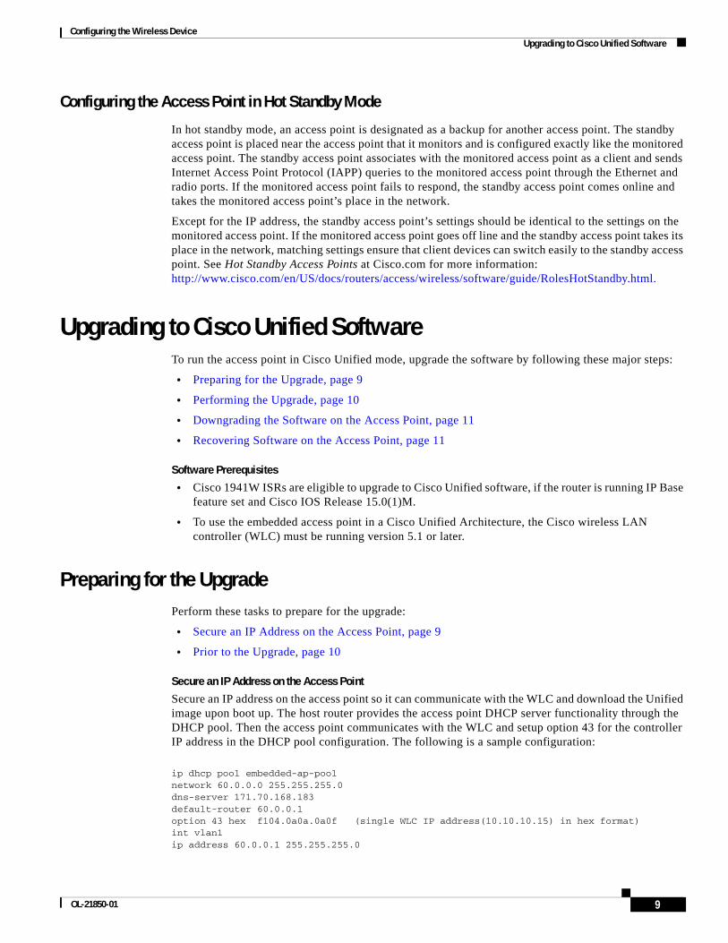
Configuring the Wireless Device Upgrading to Cisco Unified Software
Configuring the Access Point in Hot Standby Mode
In hot standby mode, an access point is designated as a backup for another access point. The standby access point is placed near the access point that it monitors and is configured exactly like the monitored access point. The standby access point associates with the monitored access point as a client and sends Internet Access Point Protocol (IAPP) queries to the monitored access point through the Ethernet and radio ports. If the monitored access point fails to respond, the standby access point comes online and takes the monitored access point’s place in the network.
Except for the IP address, the standby access point’s settings should be identical to the settings on the monitored access point. If the monitored access point goes off line and the standby access point takes its place in the network, matching settings ensure that client devices can switch easily to the standby access point. See Hot Standby Access Points at Cisco.com for more information: http://www.cisco.com/en/US/docs/routers/access/wireless/software/guide/RolesHotStandby.html.
Upgrading to Cisco Unified SoftwareTo run the access point in Cisco Unified mode, upgrade the software by following these major steps:
• Preparing for the Upgrade, page 9
• Performing the Upgrade, page 10
• Downgrading the Software on the Access Point, page 11
• Recovering Software on the Access Point, page 11
Software Prerequisites
• Cisco 1941W ISRs are eligible to upgrade to Cisco Unified software, if the router is running IP Base feature set and Cisco IOS Release 15.0(1)M.
• To use the embedded access point in a Cisco Unified Architecture, the Cisco wireless LAN controller (WLC) must be running version 5.1 or later.
Preparing for the UpgradePerform these tasks to prepare for the upgrade:
• Secure an IP Address on the Access Point, page 9
• Prior to the Upgrade, page 10
Secure an IP Address on the Access Point
Secure an IP address on the access point so it can communicate with the WLC and download the Unified image upon boot up. The host router provides the access point DHCP server functionality through the DHCP pool. Then the access point communicates with the WLC and setup option 43 for the controller IP address in the DHCP pool configuration. The following is a sample configuration:
ip dhcp pool embedded-ap-poolnetwork 60.0.0.0 255.255.255.0dns-server 171.70.168.183default-router 60.0.0.1 option 43 hex f104.0a0a.0a0f (single WLC IP address(10.10.10.15) in hex format) int vlan1ip address 60.0.0.1 255.255.255.0
9OL-21850-01

Configuring the Wireless Device Upgrading to Cisco Unified Software
For more information about the WLC discovery process, see Cisco Wireless LAN Configuration Guide at Cisco.com: http://www.cisco.com/en/US/docs/wireless/controller/4.0/configuration/guide/ccfig40.html
Prior to the Upgrade
Perform the following steps.
1. Ping the WLC from the router to confirm IP connectivity.
2. Enter the service-module wlan-ap 0 session command to establish a session with the access point.
3. Confirm that the access point is running an autonomous boot image.
4. Enter the show boot command on the access point to confirm the mode setting is enabled. The following is sample output for the command:
Autonomous-AP# show bootBOOT path-list: flash:ap801-k9w7-mx.124-10b.JA3/ap801-k9w7-mx.124-10b.JA3Config file: flash:/config.txtPrivate Config file: flash:/private-configEnable Break: yesManual Boot: yesHELPER path-list: NVRAM/Config filebuffer size: 32768Mode Button: on
Performing the UpgradeTo upgrade to Unified software, follow these steps:
Step 1 Issue the service-module wlan-ap 0 bootimage unified command to change the access point boot image to the Unified upgrade image, which is also known as a recovery image.
Router# conf terminalRouter(config)# service-module wlan-ap 0 bootimage unifiedRouter(config)# end
Note If the service-module wlan-ap 0 bootimage unified command does not work successfully, check to see whether the software license is still eligible.
On the access point console, use the show boot command to identify the access point’s boot image path:
autonomous-AP# show boot BOOT path-list: flash:/ap801-rcvk9w8-mx/ap801-rcvk9w8-mx
Step 2 Issue the service-module wlan-ap 0 reload command to perform a graceful shutdown and reboot the access point and complete the upgrade process. Session into the access point and monitor the upgrade process.
See the “Cisco Express Setup” section on page 4 for details about using the Web-based configuration page to configure the wireless device settings.
10

Configuring the Wireless Device Upgrading to Cisco Unified Software
Troubleshooting an Upgrade or Reverting the AP to Autonomous Mode
Q. My access point failed to upgrade from autonomous software to Unified software and it appears to be stuck in the recovery mode. What is my next step?
A. Check the following items:
– Is the IP address on the BVI interface on the same subnet as the WLC?
– Can you ping the WLC from the router/access point to confirm connectivity?
– Is the access point set to the current date and time? Use the show clock command to confirm this information.
Q. My access point is attempting to boot, but it keeps failing. Why? My access point is stuck in the recovery image and will not upgrade to the Unified software. Why?
A. The access point is stuck in recovery mode and you must use the service-module wlan-ap0 reset bootloader command to return the access point back to bootloader for manual image recovery.
Downgrading the Software on the Access PointUse the service-module wlan-ap0 bootimage autonomous command to reset the access point BOOT back to the last autonomous image. Use the service-module wlan-ap 0 reload command to reload the access point with the autonomous software image.
Recovering Software on the Access PointTo recover the image on the access point, use the service-module wlan-ap0 reset bootloader command. This command returns the access point to the bootloader for manual image recovery.
Caution Use this command with caution. Use this command only to recover from a shutdown or failed state.
11OL-21850-01

Configuring the Wireless Device Related Documentation
Related DocumentationSee the following documentation for additional autonomous and unified configuration information:
• Autonomous Documentation—Table 2
• Unified Documentation—Table 3
Table 2 Autonomous Documentation
Network Design Links Description
Wireless Overview “Wireless Device Overview” Describes the roles of the wireless device on the network.
Configuration Links
Configuring the Radio “Configuring Radio Settings” Describes how to configure the wireless radio.
Security Links
Authentication Types for Wireless Devices
http://www.cisco.com/en/US/docs/ routers/access/wireless/software/guide/ SecurityAuthenticationTypes.html
Describes the authentication types that are configured on the access point.
RADIUS and TACACS+ Servers in a Wireless Environment
http://www.cisco.com/en/US/docs/ routers/access/wireless/software/guide/ SecurityRadiusTacacs_1.html
Describes how to enable and configure the RADIUS1 and TACACS+2 and provides detailed accounting information and flexible administrative control over authentication and authorization processes. RADIUS and TACACS+ are facilitated through AAA and can be enabled only through AAA commands.
Using the Access Point as a Local Authenticator
http://www.cisco.com/en/US/docs/ routers/access/wireless/software/guide/ SecurityLocalAuthent.html
Describes how to use a wireless device in the role of an access point as a local authenticator, serving as a standalone authenticator for a small wireless LAN, or providing backup authentication service. As a local authenticator, the access point performs LEAP, EAP-FAST, and MAC-based authentication for up to 50 client devices.
Cipher Suites and WEP
http://www.cisco.com/en/US/docs/ routers/access/wireless/software/guide/ SecurityCipherSuitesWEP.html
Describes how to configure the cipher suites required for using WPA3 and CCKM4; WEP5; and WEP features including AES6, MIC7, TKIP8, and broadcast key rotation.
Hot Standby Access Points
http://www.cisco.com/en/US/docs/ routers/access/wireless/software/guide/RolesHotStandby.html
Describes how to configure your wireless device as a hot standby unit.
Configuring Wireless VLANs
http://www.cisco.com/en/US/docs/ routers/access/wireless/software/guide/wireless_vlans.html
Describes how to configure an access point to operate with the VLANs set up on a wired LAN.
Service Set Identifiers http://www.cisco.com/en/US/docs/ routers/access/wireless/software/guide/ ServiceSetID.html
In the role of an access point, a wireless device can support up to 16 SSIDs9. This document describes how to configure and manage SSIDs on the wireless device.
Administering Links Description
Administering the Access Point
“Administering the Wireless Device” Describes how to administer the wireless device on the network.
12

Configuring the Wireless Device Related Documentation
Quality of Service http://www.cisco.com/en/US/docs/ routers/access/wireless/software/guide/QualityOfService.html
Describes how to configure QoS10 on your Cisco wireless interface. With this feature, you can provide preferential treatment to certain traffic at the expense of other traffic. Without QoS, the device offers best-effort service to each packet, regardless of the packet contents or size. It sends the packets without any assurance of reliability, delay bounds, or throughput.
Regulatory Domains and Channels
http://www.cisco.com/en/US/docs/routers/access/800/860-880-890/software/configuration/guide/scg_chanels.html
Lists the radio channels supported by Cisco access products in the regulatory domains of the world.
System Message Logging
http://www.cisco.com/en/US/docs/ routers/access/wireless/software/guide/SysMsgLogging.html
Describes how to configure system message logging on your wireless device.
1. RADIUS = Remote Authentication Dial-In User Service
2. TACACS+ = Terminal Access Controller Access Control System Plus
3. WPA = Wireless Protected Access
4. CCKM = Cisco Centralized Key Management
5. WEP = Wired Equivalent Privacy
6. AES = Advanced Encryption Standard
7. MIC = Message Integrity Check
8. TKIP = Temporal Key Integrity Protocol
9. SSID = service set identifiers
10. QoS = quality of service
Table 3 Unified Documentation
Network Design Links
Why Migrate to the Cisco Unified Wireless Network?
http://www.cisco.com/en/US/solutions/ns175/networking_solutions_products_genericcontent0900aecd805299ff.html
Wireless LAN Controller (WLC) FAQ http://www.cisco.com/en/US/products/ps6366/products_qanda_item09186a008064a991.shtml
Cisco IOS Command Reference for Cisco Aironet Access Points and Bridges, versions 12.4(10b) JA and 12.3(8) JEC
http://www.cisco.com/en/US/docs/wireless/access_point/12.4_10b_JA/ command/reference/cr2410b.html
Cisco Aironet 1240AG Access Point Support Documentation
http://www.cisco.com/en/US/docs/wireless/access_point/1240/quick/guide/ ap1240qs.html
Cisco 4400 Series Wireless LAN Controllers Support Documentation
http://www.cisco.com/en/US/products/ps6366/ tsd_products_support_series_home.html
Table 2 Autonomous Documentation (continued)
13OL-21850-01

Configuring the Wireless Device Related Documentation
CCDE, CCENT, CCSI, Cisco Eos, Cisco HealthPresence, Cisco IronPort, the Cisco logo, Cisco Nurse Connect, Cisco Pulse, Cisco SensorBase, Cisco StackPower, Cisco StadiumVision, Cisco TelePresence, Cisco Unified Computing System, Cisco WebEx, DCE, Flip Channels, Flip for Good, Flip Mino, Flipshare (Design), Flip Ultra, Flip Video, Flip Video (Design), Instant Broadband, and Welcome to the Human Network are trademarks; Changing the Way We Work, Live, Play, and Learn, Cisco Capital, Cisco Capital (Design), Cisco:Financed (Stylized), Cisco Store, Flip Gift Card, and One Million Acts of Green are service marks; and Access Registrar, Aironet, AllTouch, AsyncOS, Bringing the Meeting To You, Catalyst, CCDA, CCDP, CCIE, CCIP, CCNA, CCNP, CCSP, CCVP, Cisco, the Cisco Certified Internetwork Expert logo, Cisco IOS, Cisco Lumin, Cisco Nexus, Cisco Press, Cisco Systems, Cisco Systems Capital, the Cisco Systems logo, Cisco Unity, Collaboration Without Limitation, Continuum, EtherFast, EtherSwitch, Event Center, Explorer, Follow Me Browsing, GainMaker, iLYNX, IOS, iPhone, IronPort, the IronPort logo, Laser Link, LightStream, Linksys, MeetingPlace, MeetingPlace Chime Sound, MGX, Networkers, Networking Academy, PCNow, PIX, PowerKEY, PowerPanels, PowerTV, PowerTV (Design), PowerVu, Prisma, ProConnect, ROSA, SenderBase, SMARTnet, Spectrum Expert, StackWise, WebEx, and the WebEx logo are registered trademarks of Cisco Systems, Inc. and/or its affiliates in the United States and certain other countries.
All other trademarks mentioned in this document or website are the property of their respective owners. The use of the word partner does not imply a partnership relationship between Cisco and any other company. (0910R)
Any Internet Protocol (IP) addresses used in this document are not intended to be actual addresses. Any examples, command display output, and figures included in the document are shown for illustrative purposes only. Any use of actual IP addresses in illustrative content is unintentional and coincidental. © 2009-2010 Cisco Systems, Inc. All rights reserved.
14
Configuring Radio Settings
The following sections describe how to configure radio settings for the wireless device:
• Enabling the Radio Interface, page 2
• Configuring the Role in the Radio Network, page 3
• Configuring Dual-Radio Fallback, page 5
• Configuring Radio Data Rates, page 6
• Configuring MCS Rates, page 9
• Configuring Radio Transmit Power, page 11
• Configuring Radio Channel Settings, page 13
• Enabling and Disabling World Mode, page 19
• Disabling and Enabling Short Radio Preambles, page 21
• Configuring Transmit and Receive Antennas, page 22
• Enabling and Disabling Gratuitous Probe Response, page 23
• Configuring the Ethernet Encapsulation Transformation Method, page 25
• Enabling and Disabling Public Secure Packet Forwarding, page 26
• Configuring the Beacon Period and the DTIM, page 28
• Configure RTS Threshold and Retries, page 29
• Configuring the Maximum Data Retries, page 30
• Configuring the Fragmentation Threshold, page 30
• Enabling Short Slot Time for 802.11g Radios, page 31
• Performing a Carrier Busy Test, page 31
• Configuring VoIP Packet Handling, page 32
Americas Headquarters:Cisco Systems, Inc., 170 West Tasman Drive, San Jose, CA 95134-1706 USA

Configuring Radio Settings Enabling the Radio Interface
Enabling the Radio InterfaceThe wireless device radios are disabled by default.
Note You must create a service set identifier (SSID) before you can enable the radio interface.
To enable the access point radio, follow these steps, beginning in privileged EXEC mode.
SUMMARY STEPS
1. configure terminal
2. dot11 ssid ssid
3. interface dot11radio {0| 1}
4. ssid ssid
5. no shutdown
6. end
7. copy running-config startup-config
DETAILED STEPS
Use the shutdown command to disable the radio port.
Command Purpose
Step 1 configure terminal Enters global configuration mode.
Step 2 dot11 ssid ssid Enters the SSID. The SSID consists of up to 32 alphanumeric characters. SSIDs are case sensitive.
Step 3 interface dot11radio {0| 1} Enters interface configuration mode for the radio interface.The 2.4-GHz and 802.11g/n 2.4-GHz radios are radio 0.
The 5-GHz and the 802.11n 5-GHz radio is radio 1.
Step 4 ssid ssid Assigns the SSID that you created in Step 2 to the appropriate radio interface.
Step 5 no shutdown Enables the radio port.
Step 6 end Returns to privileged EXEC mode.
Step 7 copy running-config startup-config (Optional) Saves your entries in the configuration file.
2

Configuring Radio Settings Configuring the Role in the Radio Network
Configuring the Role in the Radio NetworkThe radio performs the following roles in the wireless network:
• Access point
• Access point (fallback to radio shutdown)
• Root bridge
• Non-root bridge
• Root bridge with wireless clients
• Non-root bridge without wireless clients
You can also configure a fallback role for root access points. The wireless device automatically assumes the fallback role when its Ethernet port is disabled or disconnected from the wired LAN. The default fallback role for Cisco ISR wireless devices is as follows:
Shutdown—the wireless device shuts down its radio and disassociates all client devices.
To set the wireless device’s radio network role and fallback role, follow these steps, beginning in privileged EXEC mode.
SUMMARY STEPS
1. configure terminal
2. interface dot11radio {0| 1}
3. station-role
4. non-root {bridge | wireless-clients} root {access-point | ap-only | [bridge | wireless-clients] | [fallback | repeater | shutdown]}
5. workgroup-bridge {multicast | mode <client | infrastructure>| universal <Ethernet client MAC address>}
6. end
7. copy running-config startup-config
3Cisco 3900 Series, 2900 Series, and 1900 Series Integrated Services Routers Software
OL-21850-01

Configuring Radio Settings Configuring the Role in the Radio Network
DETAILED STEPS
Note When you enable the role of a device in the radio network as a bridge/workgroup bridge and enable the interface using the no shut command, the physical status and the software status of the interface will be up (ready) only if the device on the other end (access point or bridge) is up. Otherwise, only the physical status of the device will be up. The software status will be up when the device on the other end is configured and ready.
Command Purpose
Step 1 configure terminal Enters global configuration mode.
Step 2 interface dot11radio {0| 1} Enters interface configuration mode for the radio interface.
The 2.4-GHz and 802.11g/n 2.4-GHz radios are radio 0.
The 5-GHz and the 802.11n 5-GHz radio is radio 1.
Step 3 station-role non-root {bridge | wireless-clients} root {access-point | ap-only | [bridge | wireless-clients] | [fallback | repeater | shutdown]}
workgroup-bridge {multicast | mode <client | infrastructure>| universal <Ethernet client MAC address>}
Sets the wireless device role.
• Set the role to non-root bridge with or without wireless clients, to root access point or bridge, or to workgroup bridge.
Note The bridge mode radio supports point-to-point configuration only.
Note The repeater and wireless-clients commands are not supported on Cisco 1941-W Integrated Services Routers.
Note The scanner command is not supported on 1941-W Integrated Services Routers.
• The Ethernet port is shut down when any one of the radios is configured as a repeater. Only one radio per access point may be configured as a workgroup bridge or repeater. A workgroup bridge can have a maximum of 25 clients, presuming that no other wireless clients are associated to the root bridge or access point.
Step 4 end Returns to privileged EXEC mode.
Step 5 copy running-config startup-config (Optional) Saves your entries in the configuration file.
4

Configuring Radio Settings Configuring Dual-Radio Fallback
Configuring Dual-Radio FallbackThe dual-radio fallback feature, see Figure 1, allows you to configure access points so that if the non-root bridge link connecting the access point to the network infrastructure goes down, the root access point link through which a client connects to the access point shut down. Shutting down the root access point link causes the client to roam to another access point. Without this feature, the client remains connected to the access point, but won’t be able to send or receive data from the network.
Figure 1 Dual-Radio Fallback
Note This feature does not affect the fallback feature for single-radio access points.
You can configure dual-radio fallback in three ways:
• Radio tracking
• Fast Ethernet tracking
• MAC-address tracking
Radio TrackingYou can configure the access point to track or monitor the status of one of its radios. If the tracked radio goes down or is disabled, the access point shuts down the other radio. If the tracked radio comes up, the access point enables the other radio.
• To track radio 0, enter the following command:
# station-role root access-point fallback track d0 shutdown
• To track radio 1, enter the following command:
# station-role root access-point fallback track d1 shutdown
Access point
Fast Ethernet
11 a Rootbridge mode
11 b/g rootaccess point
mode
11 a Root bridgemode 11 a non-root
bridge mode
1469
30
Access pointClients
Access point
5Cisco 3900 Series, 2900 Series, and 1900 Series Integrated Services Routers Software
OL-21850-01
Configuring Radio Settings Configuring Radio Data Rates
Fast Ethernet TrackingYou can configure the access point for fallback when its Ethernet port is disabled or disconnected from the wired LAN. You configure the access point for Fast Ethernet tracking as described in the “Configuring the Role in the Radio Network” section on page 3.
Note Fast Ethernet tracking does not support the repeater mode.
• To configure the access point for Fast Ethernet tracking, enter the following command:
# station-role root access-point fallback track fa 0
MAC-Address TrackingYou can configure the radio, whose role is root access point, to come up or go down by tracking a client access point, and using its MAC address on another radio. If the client disassociates from the access point, the root access point radio goes down. If the client reassociates with the access point, the root access point radio comes back up.
MAC-address tracking is most useful when the client is a non-root bridge access point connected to an upstream wired network.
For example, to track a client whose MAC address is 12:12:12:12:12:12, enter the following command:
# station-role root access-point fallback track mac-address 12:12:12:12:12:12 shutdown
Configuring Radio Data RatesYou use the data rate settings to choose the data rates that the wireless device uses for data transmission. The rates are expressed in megabits per second (Mb/s). The wireless device always attempts to transmit at the highest data rate set to basic, also known as required on the browser-based interface. If there are obstacles or interference, the wireless device steps down to the highest rate that allows data transmission. You can set each data rate to one of three states:
• Basic (the GUI labels Basic rates as Required)—Allows transmission at this rate for all packets, both unicast and multicast. At least one of the wireless device’s data rates must be set to basic.
• Enabled—The wireless device transmits only unicast packets at this rate; multicast packets are sent at one of the data rates set to basic.
• Disabled—The wireless device does not transmit data at this rate.
Note At least one data rate must be set to basic.
You can use the data rate settings to set an access point to serve client devices operating at specific data rates. For example, to set the 2.4-GHz radio for 11 Mb/s service only, set the 11-Mb/s rate to basic, and set the other data rates to disabled. To set the wireless device to serve only client devices operating at 1 and 2 Mb/s, set 1 and 2 to basic, and set the rest of the data rates to disabled. To set the 2.4-GHz, 802.11g radio to serve only 802.11g client devices, set any orthogonal frequency division multiplexing (OFDM) data rate (6, 9, 12, 18, 24, 36, 48, 54) to basic. To set the 5-GHz radio for 54-Mb/s service only, set the 54-Mb/s rate to basic, and set the other data rates to disabled.
6
Configuring Radio Settings Configuring Radio Data Rates
You can configure the wireless device to set the data rates automatically to optimize either the range or the throughput. When you enter range for the data rate setting, the wireless device sets the 1-Mb/s rate to basic and sets the other rates to enabled.
The range setting allows the access point to extend the coverage area by compromising on the data rate. Therefore, if you have a client that cannot connect to the access point while other clients can, the client might not be within the coverage area of the access point. In such a case, using the range option will help extend the coverage area, and the client may be able to connect to the access point. Typically the trade-off is between throughput and range.
When the signal degrades (possibly due to distance from the access point), the rates renegotiate in order to maintain the link (but at a lower data rate). A link that is configured for a higher throughput simply drops when the signal degrades enough that it no longer sustains a configured high data rate, or the link roams to another access point with sufficient coverage, if one is available.
The balance between the two (throughput vs. range) is a design decision that must be made based on resources available to the wireless project, the type of traffic the users will be passing, the service level desired, and as always, the quality of the RF environment.When you enter throughput for the data rate setting, the wireless device sets all four data rates to basic.
Note When a wireless network has a mixed environment of 802.11b clients and 802.11g clients, make sure that data rates 1, 2, 5.5, and 11 Mb/s are set to required (basic) and that all other data rates are set to enable. The 802.11b adapters do not recognize the 54 Mb/s data rate and do not operate if data rates higher than 11 Mb/s are set to required on the connecting access point.
To configure the radio data rates, follow these steps, beginning in privileged EXEC mode.
SUMMARY STEPS
1. configure terminal
2. interface dot11radio {0 | 1}
3. speed parameters
4. end
5. copy running-config startup-config
DETAILED STEPS
Command Purpose
Step 1 configure terminal Enters global configuration mode.
Step 2 interface dot11radio {0 | 1} Enters interface configuration mode for the radio interface. The 2.4-GHz and the 802.11g/n 2.4-GHz radios are radio 0.
The 5-GHz and the 802.11n 5-GHz radio is radio 1.
7Cisco 3900 Series, 2900 Series, and 1900 Series Integrated Services Routers Software
OL-21850-01

Configuring Radio Settings Configuring Radio Data Rates
Step 3 speed
802.11b, 2.4-GHz radio:
{[1.0] [11.0] [2.0] [5.5] [basic-1.0] [basic-11.0] [basic-2.0] [basic-5.5] | range | throughput}
802.11g, 2.4-GHz radio:
{[1.0] [2.0] [5.5] [6.0] [9.0] [11.0] [12.0] [18.0] [24.0] [36.0] [48.0] [54.0] [basic-1.0] [basic-2.0] [basic-5.5] [basic-6.0] [basic-9.0] [basic-11.0] [basic-12.0] [basic-18.0] [basic-24.0] [basic-36.0] [basic-48.0] [basic-54.0] | range | throughput [ofdm] | default}
802.11a 5-GHz radio:
{[6.0] [9.0] [12.0] [18.0] [24.0] [36.0] [48.0] [54.0] [basic-6.0] [basic-9.0] [basic-12.0] [basic-18.0] [basic-24.0] [basic-36.0] [basic-48.0] [basic-54.0] | range | throughput | ofdm-throughput | default}
802.11n 2.4-GHz radio:
{[1.0] [11.0] [12.0] [18.0] [2.0] [24.0] [36.0] [48.0] [5.5] [54.0] [6.0] [9.0] [basic-1.0] [basic-11.0] [basic-12.0] [basic-18.0] [basic-24.0] [basic-36.0] [basic-48.0] [basic-5.5] [basic-54.0] [basic-6.0] [basic-9.0] [default] [m0-7] [m0.] [m1.] [m10.] [m11.] [m12.] [m13.] [m14.] [m15.] [m2.] [m3.] [m4.] [m5.] [m6.] [m7.] [m8-15] [m8.] [m9.] [ofdm] [only-ofdm] | range | throughput}
802.11n 5-GHz radio:
{[12.0] [18.0] [24.0] [36.0] [48.0] [54.0] [6.0] [9.0] [basic-12.0] [basic-18.0] [basic-24.0] [basic-36.0] [basic-48.0] [basic-54.0] [basic-6.0] [basic-9.0] [default] [m0-7] [m0.] [m1.] [m10.] [m11.] [m12.] [m13.] [m14.] [m15.] [m2.] [m3.] [m4.] [m5.] [m6.] [m7.] [m8-15] [m8.] [m9.] | range | throughput}
Sets each data rate to basic or enabled, or enters range to optimize range or enters throughput to optimize throughput.
• (Optional) Enter 1.0, 2.0, 5.5, and 11.0 to set these data rates to enabled on the 802.11b, 2.4-GHz radio.
Enter 1.0, 2.0, 5.5, 6.0, 9.0, 11.0, 12.0, 18.0, 24.0, 36.0, 48.0, and 54.0 to set these data rates to enabled on the 802.11g, 2.4-GHz radio.
Enter 6.0, 9.0, 12.0, 18.0, 24.0, 36.0, 48.0, and 54.0 to set these data rates to enabled on the 5-GHz radio.
• (Optional) Enter basic-1.0, basic-2.0, basic-5.5, and basic-11.0 to set these data rates to basic on the 802.11b, 2.4-GHz radio.
Enter basic-1.0, basic-2.0, basic-5.5, basic-6.0, basic-9.0, basic-11.0, basic-12.0, basic-18.0, basic-24.0, basic-36.0, basic-48.0, and basic-54.0 to set these data rates to basic on the 802.11g, 2.4-GHz radio.
Note If the client must support the basic rate that you select, it cannot associate to the wireless device. If you select 12-Mb/s or higher for the basic data rate on the 802.11g radio, 802.11b client devices cannot associate to the wireless device 802.11g radio.
Enter basic-6.0, basic-9.0, basic-12.0, basic-18.0, basic-24.0, basic-36.0, basic-48.0, and basic-54.0 to set these data rates to basic on the 5-GHz radio.
• (Optional) Enter range or throughput or ofdm-throughput (no ERP protection) to automatically optimize radio range or throughput. When you enter range, the wireless device sets the lowest data rate to basic and sets the other rates to enabled. When you enter throughput, the wireless device sets all data rates to basic.
(Optional) On the 802.11g radio, enter speed throughput ofdm to set all OFDM rates (6, 9, 12, 18, 24, 36, and 48) to basic (required) and to set all the CCK rates (1, 2, 5.5, and 11) to disabled. This setting disables 802.11b protection mechanisms and provides maximum throughput for 802.11g clients. However, it prevents 802.11b clients from associating to the access point.
• (Optional) Enter default to set the data rates to factory default settings (not supported on 802.11b radios).
On the 802.11g radio, the default option sets rates 1, 2, 5.5, and 11 to basic, and sets rates 6, 9, 12, 18, 24, 36, 48, and 54 to enabled. These rate settings allow both 802.11b and 802.11g client devices to associate to the wireless device 802.11g radio.
On the 5-GHz radio, the default option sets rates 6.0, 12.0, and 24.0 to basic, and sets rates 9.0, 18.0, 36.0, 48.0, and 54.0 to enabled.
On the 802.11g/n 2.4-GHz radio, the default option sets rates 1.0, 2.0, 5.5, and 11.0 to enabled.
On the 802.11g/n 5-GHz radio, the default option sets rates to 6.0, 12.0, and 24.0 to enabled.
The modulation coding scheme (MCS) index range for both 802.11g/n radios is 0 to 15.
Command Purpose
8

Configuring Radio Settings Configuring MCS Rates
Use the no form of the speed command to remove one or more data rates from the configuration. This example shows how to remove data rates basic-2.0 and basic-5.5 from the configuration:
ap1200# configure terminalap1200(config)# interface dot11radio 0ap1200(config-if)# no speed basic-2.0 basic-5.5ap1200(config-if)# end
Configuring MCS RatesModulation coding scheme (MCS) is a specification of PHY parameters consisting of modulation order (binary phase shift keying [BPSK], quaternary phase shift keying [QPSK], 16-quadrature amplitude modulation [16-QAM], 64-QAM) and forward error correction (FEC) code rate (1/2, 2/3, 3/4, 5/6). MCS is used in the wireless device 802.11n radios, which define 32 symmetrical settings (8 per spatial stream):
• MCS 0–7
• MCS 8–15
• MCS 16–23
• MCS 24–31
The wireless device supports MCS 0–15. High-throughput clients support at least MCS 0–7.
MCS is an important setting because it provides for potentially greater throughput. High-throughput data rates are a function of MCS, bandwidth, and guard interval. The 802.11a, b, and g radios use 20-MHz channel widths. Table 1 shows potential data rated based on MCS, guard interval, and channel width.
Step 4 end Returns to privileged EXEC mode.
Step 5 copy running-config startup-config
(Optional) Saves your entries in the configuration file.
Command Purpose
9Cisco 3900 Series, 2900 Series, and 1900 Series Integrated Services Routers Software
OL-21850-01

Configuring Radio Settings Configuring MCS Rates
MCS rates are configured using the speed command. The following example shows a speed setting for an 802.11g/n 2.4-GHz radio:
interface Dot11Radio0no ip addressno ip route-cache!ssid 800test!speed basic-1.0 2.0 5.5 11.0 6.0 9.0 12.0 18.0 24.0 36.0 48.0 54.0 m0. m1. m2. m3. m4. m8. m9. m10. m11. m12. m13. m14. m15.
Table 1 Data Rates Based on MCS Settings, Guard Interval, and Channel Width
MCS Index Guard Interval = 800 ns Guard Interval = 400 ns
20-MHz Channel Width Data Rate (Mb/s)
40-MHz Channel Width Data Rate (Mb/s)
20-MHz Channel Width Data Rate (Mb/s)
40-MHz Channel Width Data Rate (Mb/s)
0 6.5 13.5 7 2/9 15
1 13 27 14 4/9 30
2 19.5 40.5 21 2/3 45
3 26 54 28 8/9 60
4 39 81 43 1/3 90
5 52 109 57 5/9 120
6 58.5 121.5 65 135
7 65 135 72 2/9 152.5
8 13 27 14 4/9 30
9 26 54 28 8/9 60
10 39 81 43 1/3 90
11 52 108 57 7/9 120
12 78 162 86 2/3 180
13 104 216 115 5/9 240
14 117 243 130 270
15 130 270 144 4/9 300
The legacy rates are as follows:
5 GHz: 6, 9, 12, 18, 24, 36, 48, and 54 Mb/s
2.4 GHz: 1, 2, 5.5, 6, 9, 11, 12, 18, 24, 36, 48, and 54 Mb/s
10

Configuring Radio Settings Configuring Radio Transmit Power
Configuring Radio Transmit PowerRadio transmit power is based on the type of radio or radios installed in your access point and the regulatory domain in which it operates.
To set the transmit power on access point radios, follow these steps, beginning in privileged EXEC mode.
SUMMARY STEPS
1. configure terminal
2. interface dot11radio {0| 1}
3. power local level
4. end
5. copy running-config startup-config
DETAILED STEPS
Use the no form of the power local command to return the power setting to maximum, the default setting.
Limiting the Power Level for Associated Client DevicesYou can also limit the power level on client devices that associate to the wireless device. When a client device associates to the wireless device, the wireless device sends the maximum power level setting to the client.
Note Cisco AVVID documentation uses the term Dynamic Power Control (DPC) to refer to limiting the power level on associated client devices.
To specify a maximum allowed power setting on all client devices that associate to the wireless device, follow these steps, beginning in privileged EXEC mode.
Command Purpose
Step 1 configure terminal Enters global configuration mode.
Step 2 interface dot11radio {0| 1} Enters interface configuration mode for the radio interface.
The 2.4-GHz and the 802.11g/n 2.4-GHz radios are radio 0.
The 5-GHz and the 802.11n 5-GHz radio is radio 1.
Step 3 power local
These options are available for the 2.4-GHz 802.11n radio (in dBm):
{8 | 9| 11 | 14 | 15 | 17 | maximum}
Sets the transmit power for the radio, or the 5-GHz radio so that the power level is allowed in your regulatory domain.
Step 4 end Returns to privileged EXEC mode.
Step 5 copy running-config startup-config (Optional) Saves your entries in the configuration file.
11Cisco 3900 Series, 2900 Series, and 1900 Series Integrated Services Routers Software
OL-21850-01

Configuring Radio Settings Configuring Radio Transmit Power
SUMMARY STEPS
1. configure terminal
2. interface dot11radio {0| 1}
3. power client level
4. end
5. copy running-config startup-config
DETAILED STEPS
Use the no form of the power client command to disable the maximum power level for associated clients.
Note Aironet extensions must be enabled to limit the power level on associated client devices. Aironet extensions are enabled by default.
Command Purpose
Step 1 configure terminal Enters global configuration mode.
Step 2 interface dot11radio {0| 1} Enters interface configuration mode for the radio interface. The 2.4-GHz and 802.11g/n 2.4-GHz radios are radio 0.
The 5-GHz and the 802.11n 5-GHz radio is radio 1.
Step 3 power client
These options are available for 802.11n 2.4-GHz clients (in dBm):
{local | 8 | 9 | 11 | 14 | 15 | 17 | maximum}
These options are available for 802.11n 5-GHz clients (in dBm):
{local | 8 | 11 | 13 | 14 | 15 | maximum}
Sets the maximum power level allowed on client devices that associate to the wireless device.
Setting the power level to local sets the client power level to that of the access point.
Setting the power level to maximum sets the client power to the allowed maximum.
Note The settings allowed in your regulatory domain might differ from the settings listed here.
Step 4 end Returns to privileged EXEC mode.
Step 5 copy running-config startup-config (Optional) Saves your entries in the configuration file.
12

Configuring Radio Settings Configuring Radio Channel Settings
Configuring Radio Channel SettingsThe default channel setting for the wireless device radios is least congested. At startup, the wireless device scans for and selects the least-congested channel. For the most consistent performance after a site survey, however, we recommend that you assign a static channel setting for each access point. The channel settings on the wireless device correspond to the frequencies available in your regulatory domain. See the hardware installation guide for the access point for the frequencies allowed in your domain.
Each 2.4-GHz channel covers 22 MHz. Because the bands for channels 1, 6, and 11 do not overlap, you can set up multiple access points in the same vicinity without causing interference. The 802.11b and 802.11g 2.4-GHz radios use the same channels and frequencies.
The 5-GHz radio operates on 8 channels from 5180 to 5320 MHz, up to 27 channels from 5170 to 5850 MHz depending on regulatory domain. Each channel covers 20 MHz, and the bands for the channels overlap slightly. For best performance, use channels that are not adjacent (use channels 44 and 46, for example) for radios that are close to each other.
Caution The presence of too many access points in the same vicinity can create radio congestion that can reduce throughput. A careful site survey can determine the best placement of access points for maximum radio coverage and throughput.
802.11n Channel WidthsThe 802.11n standard allows both 20-MHz and 40-Mhz channel widths consisting of two contiguous non-overlapping channels (for example, 2.4-GHz channels 1 and 6).
One of the 20-MHz channels is called the control channel. Legacy clients and 20-MHz high-throughput clients use the control channel. Only beacons can be sent on this channel. The second 20-MHz channel is called the extension channel. The 40-MHz stations may use this channel and the control channel simultaneously.
A 40-MHz channel is specified as a channel and extension, such as 1,1. In this example, the control channel is channel 1 and the extension channel is above it.
To set the wireless device channel width, follow these steps, beginning in privileged EXEC mode.
SUMMARY STEPS
1. configure terminal
2. interface dot11radio {0 | 1}
3. channel {frequency | least-congested | width [20 | 40-above | 40-below] | dfs}
4. end
5. copy running-config startup-config
13Cisco 3900 Series, 2900 Series, and 1900 Series Integrated Services Routers Software
OL-21850-01

Configuring Radio Settings Configuring Radio Channel Settings
DETAILED STEPS
Dynamic Frequency SelectionAccess points with 5-GHz radios configured at the factory for use in the United States, Europe, Singapore, Korea, Japan, Israel, and Taiwan now comply with regulations that require radio devices to use Dynamic Frequency Selection (DFS) to detect radar signals and avoid interfering with them. When an access points detects a radar on a certain channel, it avoids using that channel for 30 minutes. Radios configured for use in other regulatory domains do not use DFS.
When a DFS-enabled 5-GHz radio operates on one of the 15 channels listed in Table 2, the access point automatically uses DFS to set the operating frequency. When DFS is enabled, the access point monitors its operating frequency for radar signals. If it detects radar signals on the channel, the access point takes these steps:
• Blocks new transmissions on the channel.
• Flushes the power-save client queues.
• Broadcasts an 802.11h channel-switch announcement.
• Disassociates remaining client devices.
• If participating in WDS, sends a DFS notification to the active WDS device that it is leaving the frequency.
Command Purpose
Step 1 configure terminal Enters global configuration mode.
Step 2 interface dot11radio {0 | 1} Enters interface configuration mode for the radio interface. The 802.11g/n 2.4-GHz radio is radio 0.
The 802.11n 5-GHz radio is radio 1.
Step 3 channel {frequency | least-congested | width [20 | 40-above | 40-below] | dfs}
Sets the default channel for the wireless device radio.To search for the least-congested channel on startup, enter least-congested.
Use the width option to specify a bandwidth to use. This option is available for the Cisco 800 series ISR wireless devices and consists of three available settings: 20, 40-above, and 40-below:
• Choosing 20 sets the channel width to 20 MHz.
• Choosing 40-above sets the channel width to 40 MHz with the extension channel above the control channel.
• Choosing 40-below sets the channel width to 40 MHz with the extension channel below the control channel.
Note The channel command is disabled for 5-GHz radios that comply with European Union regulations on dynamic frequency selection (DFS). See the “Enabling and Disabling World Mode” section on page 19 for more information.
Step 4 end Returns to privileged EXEC mode.
Step 5 copy running-config startup-config
(Optional) Saves your entries in the configuration file.
14
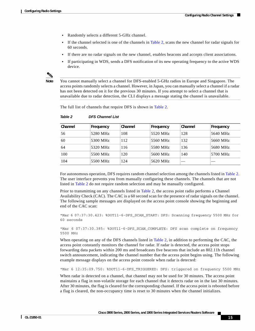
Configuring Radio Settings Configuring Radio Channel Settings
• Randomly selects a different 5-GHz channel.
• If the channel selected is one of the channels in Table 2, scans the new channel for radar signals for 60 seconds.
• If there are no radar signals on the new channel, enables beacons and accepts client associations.
• If participating in WDS, sends a DFS notification of its new operating frequency to the active WDS device.
Note You cannot manually select a channel for DFS-enabled 5-GHz radios in Europe and Singapore. The access points randomly selects a channel. However, in Japan, you can manually select a channel if a radar has not been detected on it for the previous 30 minutes. If you attempt to select a channel that is unavailable due to radar detection, the CLI displays a message stating the channel is unavailable.
The full list of channels that require DFS is shown in Table 2.
For autonomous operation, DFS requires random channel selection among the channels listed in Table 2. The user interface prevents you from manually configuring these channels. The channels that are not listed in Table 2 do not require random selection and may be manually configured.
Prior to transmitting on any channels listed in Table 2, the access point radio performs a Channel Availability Check (CAC). The CAC is a 60 second scan for the presence of radar signals on the channel. The following sample messages are displayed on the access point console showing the beginning and end of the CAC scan:
*Mar 6 07:37:30.423: %DOT11-6-DFS_SCAN_START: DFS: Scanning frequency 5500 MHz for 60 seconds
*Mar 6 07:37:30.385: %DOT11-6-DFS_SCAN_COMPLETE: DFS scan complete on frequency 5500 MHz
When operating on any of the DFS channels listed in Table 2, in addition to performing the CAC, the access point constantly monitors the channel for radar. If radar is detected, the access point stops forwarding data packets within 200 ms and broadcasts five beacons that include an 802.11h channel switch announcement, indicating the channel number that the access point begins using. The following example message displays on the access point console when radar is detected:
*Mar 6 12:35:09.750: %DOT11-6-DFS_TRIGGERED: DFS: triggered on frequency 5500 MHz
When radar is detected on a channel, that channel may not be used for 30 minutes. The access point maintains a flag in non-volatile storage for each channel that it detects radar on in the last 30 minutes. After 30 minutes, the flag is cleared for the corresponding channel. If the access point is rebooted before a flag is cleared, the non-occupancy time is reset to 30 minutes when the channel initializes.
Table 2 DFS Channel List
Channel Frequency Channel Frequency Channel Frequency
56 5280 MHz 108 5520 MHz 128 5640 MHz
60 5300 MHz 112 5560 MHz 132 5660 MHz
64 5320 MHz 116 5580 MHz 136 5680 MHz
100 5500 MHz 120 5600 MHz 140 5700 MHz
104 5500 MHz 124 5620 MHz — —
15Cisco 3900 Series, 2900 Series, and 1900 Series Integrated Services Routers Software
OL-21850-01
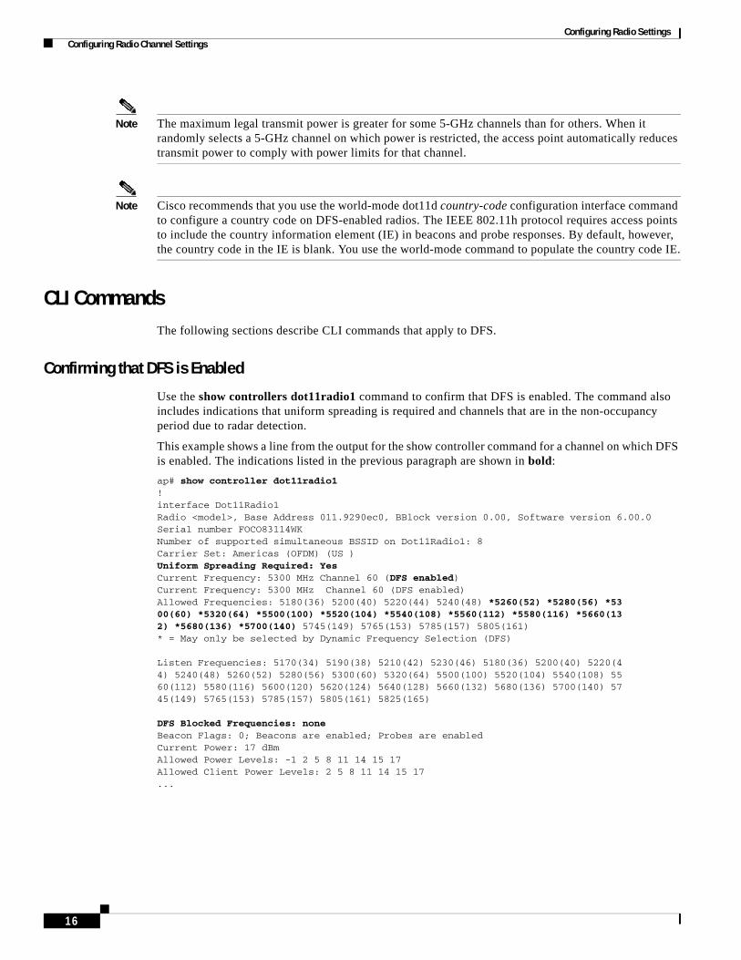
Configuring Radio Settings Configuring Radio Channel Settings
Note The maximum legal transmit power is greater for some 5-GHz channels than for others. When it randomly selects a 5-GHz channel on which power is restricted, the access point automatically reduces transmit power to comply with power limits for that channel.
Note Cisco recommends that you use the world-mode dot11d country-code configuration interface command to configure a country code on DFS-enabled radios. The IEEE 802.11h protocol requires access points to include the country information element (IE) in beacons and probe responses. By default, however, the country code in the IE is blank. You use the world-mode command to populate the country code IE.
CLI CommandsThe following sections describe CLI commands that apply to DFS.
Confirming that DFS is Enabled
Use the show controllers dot11radio1 command to confirm that DFS is enabled. The command also includes indications that uniform spreading is required and channels that are in the non-occupancy period due to radar detection.
This example shows a line from the output for the show controller command for a channel on which DFS is enabled. The indications listed in the previous paragraph are shown in bold:
ap# show controller dot11radio1!interface Dot11Radio1Radio <model>, Base Address 011.9290ec0, BBlock version 0.00, Software version 6.00.0Serial number FOCO83114WKNumber of supported simultaneous BSSID on Dot11Radio1: 8Carrier Set: Americas (OFDM) (US )Uniform Spreading Required: YesCurrent Frequency: 5300 MHz Channel 60 (DFS enabled)Current Frequency: 5300 MHz Channel 60 (DFS enabled)Allowed Frequencies: 5180(36) 5200(40) 5220(44) 5240(48) *5260(52) *5280(56) *5300(60) *5320(64) *5500(100) *5520(104) *5540(108) *5560(112) *5580(116) *5660(132) *5680(136) *5700(140) 5745(149) 5765(153) 5785(157) 5805(161)* = May only be selected by Dynamic Frequency Selection (DFS)
Listen Frequencies: 5170(34) 5190(38) 5210(42) 5230(46) 5180(36) 5200(40) 5220(44) 5240(48) 5260(52) 5280(56) 5300(60) 5320(64) 5500(100) 5520(104) 5540(108) 5560(112) 5580(116) 5600(120) 5620(124) 5640(128) 5660(132) 5680(136) 5700(140) 5745(149) 5765(153) 5785(157) 5805(161) 5825(165)
DFS Blocked Frequencies: noneBeacon Flags: 0; Beacons are enabled; Probes are enabledCurrent Power: 17 dBmAllowed Power Levels: -1 2 5 8 11 14 15 17Allowed Client Power Levels: 2 5 8 11 14 15 17...
16

Configuring Radio Settings Configuring Radio Channel Settings
Configuring a Channel
Use the channel command to configure a channel. The command for the interface is modified to only allow you to select a specific channel number and to enable DFS.
To configure a channel, follow these steps.
SUMMARY STEPS
1. configure terminal
2. interface dot11radio1 dfs simulate
3. channel {number | dfs band <1–4>}
4. end
5. show running-config
6. copy running-config startup-config
DETAILED STEPS
The following example selects channel 36 and configures it to use DFS on a frequency band 1:
ap# configure terminal ap(config)interface dot11radio1 ap(config-if) channel 36 ap(config-if)
Command Purpose
Step 1 configure terminal Enters global configuration mode.
Step 2 interface dot11radio1 dfs simulate Enters the configuration interface for the 802.11a radio
Step 3 channel {number | dfs band <1–4>} Specifies the channel to use.
For number, enter one of the following channels: 36, 40, 44, 48, 149, 153, 157, 161, 5180, 5200, 5220, 5240, 5745, 5765, 5785, or 5805.
Enter dfs and one of the following frequency bands to use dynamic frequency selection on the selected channel:
1—5.150 to 5.250 GHz
2—5.250 to 5.350 Ghz
3—5.470 to 5.725 GHz
4—5.725 to 5.825 GHz
If you attempt to configure a channel that may only be selected by dfs, the following message appears:
This channel number/frequency can only be used by Dynamic Frequency Selection (DFS)
Step 4 end Returns to the privileged EXEC mode.
Step 5 show running-config Verifies your entries
Step 6 copy running-config startup-config (Optional) Saves your entries to the configuration file.
17Cisco 3900 Series, 2900 Series, and 1900 Series Integrated Services Routers Software
OL-21850-01

Configuring Radio Settings Configuring Radio Channel Settings
Blocking Channels from DFS Selection
If your regulatory domain limits the channels that you can use in specific locations—for example, indoors or outdoors—you can block groups of channels to prevent the access point from selecting them when DFS is enabled. Use this configuration interface command to block groups of channels from DFS selection:
[no] dfs band [1] [2] [3] [4] block
The 1, 2, 3, and 4 options designate blocks of channels:
• 1—Specifies frequencies 5.150 to 5.250 GHz. This group of frequencies is also known as the UNII-1 band.
• 2—Specifies frequencies 5.250 to 5.350 GHz. This group of frequencies is also known as the UNII-2 band.
• 3—Specifies frequencies 5.470 to 5.725 GHz.
• 4—Specifies frequencies 5.725 to 5.825 GHz. This group of frequencies is also known as the UNII-3 band.
This example shows how to prevent the access point from selecting frequencies 5.150 to 5.350 GHz during DFS:
ap(config-if)# dfs band 1 2 block
This example shows how to unblock frequencies 5.150 to 5.350 for DFS:
ap(config-if)# no dfs band 1 2 block
This example shows how to unblock all frequencies for DFS:
ap(config-if)# no dfs band block
Simulating Radar Detection
You can simulate radar detection on the current channel using the debug dot11 dfs simulate command. The following example simulates radar on dfs channel 36. Five beacons are sent.
ap>enablePassword:ap#debug dot11 dot11radio1 dfs simulate 36 5
The following is an example message displayed on the console when radar is detected:
*Mar 6 12:35:09.750: %DOG11-6-DFS_TRIGGERED: DFS: triggered on frequency 5500 MHz
18

Configuring Radio Settings Enabling and Disabling World Mode
Setting the 802.11n Guard IntervalThe 802.11n guard interval is the period in nanoseconds between packets. Two settings are available: short (400ns) and long (800ns).
To to set the 802.11n guard interval, follow these steps, beginning in privileged EXEC mode.
SUMMARY STEPS
1. configure terminal
2. interface dot11radio {0 | 1}
3. guard-interval {any | long}
4. end
5. copy running-config startup-config
DETAILED STEPS
Enabling and Disabling World ModeYou can configure the wireless device to support 802.11d world mode, Cisco legacy world mode, or world mode roaming. When you enable world mode, the wireless device adds channel carrier set information to its beacon. Client devices with world mode enabled receive the carrier set information and adjust their settings automatically. For example, a client device used primarily in Japan could rely on world mode to adjust its channel and power settings automatically when it travels to Italy and joins a network there. Cisco client devices detect whether the wireless device is using 802.11d or Cisco legacy world mode and automatically use the world mode that matches the mode used by the wireless device.
You can also configure world mode to be always on. In this configuration, the access point essentially roams between countries and changes its settings as required.
World mode is disabled by default.
To enable world mode, follow these steps, beginning in privileged EXEC mode.
Command Purpose
Step 1 configure terminal Enters global configuration mode.
Step 2 interface dot11radio {0 | 1} Enters interface configuration mode for the radio interface.The 802.11n 2.4-GHz radio is radio 0.
The 802.11n 5-GHz radio is radio 1.
Step 3 guard-interval {any | long} Specifies a guard interval.
• any allows either the short (400ns) or long (800ns) guard interval.
• long allows only the long (800ns) guard interval.
Step 4 end Returns to privileged EXEC mode.
Step 5 copy running-config startup-config
(Optional) Saves your entries in the configuration file.
19Cisco 3900 Series, 2900 Series, and 1900 Series Integrated Services Routers Software
OL-21850-01

Configuring Radio Settings Enabling and Disabling World Mode
SUMMARY STEPS
1. configure terminal
2. interface dot11radio {0| 1}
3. world-mode {dot11d country_code code {both | indoor | outdoor} | world-mode roaming | legacy}
4. end
5. copy running-config startup-config
DETAILED STEPS
Use the no form of the world-mode command to disable world mode.
Command Purpose
Step 1 configure terminal Enters global configuration mode.
Step 2 interface dot11radio {0| 1} Enters interface configuration mode for the radio interface.
Step 3 world-mode {dot11d country_code code {both | indoor | outdoor} | world-mode roaming | legacy}
Enables world mode.
• Enter the dot11d option to enable 802.11d world mode.
– When you enter the dot11d option, you must enter a 2-character ISO country code (for example, the ISO country code for the United States is US). You can find a list of ISO country codes at the ISO website.
– After the country code, you must enter indoor, outdoor, or both to indicate the placement of the wireless device.
• Enter the legacy option to enable Cisco legacy world mode.
• Enter the world-mode roaming option to place the access point in a continuous world mode configuration.
Note Aironet extensions must be enabled for legacy world mode operation, but Aironet extensions are not required for 802.11d world mode. Aironet extensions are enabled by default.
Step 4 end Returns to privileged EXEC mode.
Step 5 copy running-config startup-config (Optional) Saves your entries in the configuration file.
20

Configuring Radio Settings Disabling and Enabling Short Radio Preambles
Disabling and Enabling Short Radio PreamblesThe radio preamble (sometimes called a header) is a section of data at the head of a packet that contains information that the wireless device and client devices need when sending and receiving packets. You can set the radio preamble to long or short:
• Short—A short preamble improves throughput performance.
• Long—A long preamble ensures compatibility between the wireless device and all early models of Cisco Aironet Wireless LAN Adapters. If these client devices do not associate to the wireless devices, you should use short preambles.
You cannot configure short or long radio preambles on the 5-GHz radio.
To disable short radio preambles, follow these steps, beginning in privileged EXEC mode:
SUMMARY STEPS
1. configure terminal
2. interface dot11radio {0| 1}
3. no preamble-short
4. end
5. copy running-config startup-config
DETAILED STEPS
Short preambles are enabled by default. Use the preamble-short command to enable short preambles if they are disabled.
Command Purpose
Step 1 configure terminal Enters global configuration mode.
Step 2 interface dot11radio {0| 1} Enters interface configuration mode for the 2.4-GHz radio interface.
Step 3 no preamble-short Disables short preambles and enable long preambles.
Step 4 end Returns to privileged EXEC mode.
Step 5 copy running-config startup-config (Optional) Saves your entries in the configuration file.
21Cisco 3900 Series, 2900 Series, and 1900 Series Integrated Services Routers Software
OL-21850-01
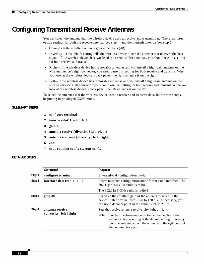
Configuring Radio Settings Configuring Transmit and Receive Antennas
Configuring Transmit and Receive AntennasYou can select the antenna that the wireless device uses to receive and transmit data. There are three option settings for both the receive antenna (see step 4) and the transmit antenna (see step 5):
• Gain—Sets the resultant antenna gain in decibels (dB).
• Diversity—This default setting tells the wireless device to use the antenna that receives the best signal. If the wireless device has two fixed (non-removable) antennas, you should use this setting for both receive and transmit.
• Right—If the wireless device has removable antennas and you install a high-gain antenna on the wireless device’s right connector, you should use this setting for both receive and transmit. When you look at the wireless device’s back panel, the right antenna is on the right.
• Left—If the wireless device has removable antennas and you install a high-gain antenna on the wireless device’s left connector, you should use this setting for both receive and transmit. When you look at the wireless device’s back panel, the left antenna is on the left.
To select the antennas that the wireless device uses to receive and transmit data, follow these steps, beginning in privileged EXEC mode.
SUMMARY STEPS
1. configure terminal
2. interface dot11radio {0| 1}
3. gain dB
4. antenna receive {diversity | left | right}
5. antenna transmit {diversity | left | right}
6. end
7. copy running-config startup-config
DETAILED STEPS
Command Purpose
Step 1 configure terminal Enters global configuration mode.
Step 2 interface dot11radio {0| 1} Enters interface configuration mode for the radio interface. The 802.11g/n 2.4-GHz radio is radio 0.
The 802.11n 5-GHz radio is radio 1.
Step 3 gain dB Specifies the resultant gain of the antenna attached to the device. Enter a value from –128 to 128 dB. If necessary, you can use a decimal point in the value, such as “1.5”.
Step 4 antenna receive {diversity | left | right}
Sets the receive antenna to diversity, left, or right.
Note For best performance with two antennas, leave the receive antenna setting at the default setting, diversity. For one antenna, attach the antenna on the right and set the antenna for right.
22
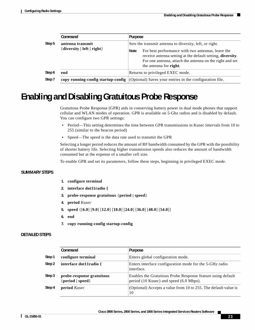
Configuring Radio Settings Enabling and Disabling Gratuitous Probe Response
Enabling and Disabling Gratuitous Probe ResponseGratuitous Probe Response (GPR) aids in conserving battery power in dual mode phones that support cellular and WLAN modes of operation. GPR is available on 5-Ghz radios and is disabled by default. You can configure two GPR settings:
• Period—This setting determines the time between GPR transmissions in Kusec intervals from 10 to 255 (similar to the beacon period)
• Speed—The speed is the data rate used to transmit the GPR
Selecting a longer period reduces the amount of RF bandwidth consumed by the GPR with the possibility of shorter battery life. Selecting higher transmission speeds also reduces the amount of bandwidth consumed but at the expense of a smaller cell size.
To enable GPR and set its parameters, follow these steps, beginning in privileged EXEC mode.
SUMMARY STEPS
1. configure terminal
2. interface dot11radio {
3. probe-response gratuitous {period | speed}
4. period Kusec
5. speed {[6.0] [9.0] [12.0] [18.0] [24.0] [36.0] [48.0] [54.0]}
6. end
7. copy running-config startup-config
DETAILED STEPS
Step 5 antenna transmit {diversity | left | right}
Sets the transmit antenna to diversity, left, or right.
Note For best performance with two antennas, leave the receive antenna setting at the default setting, diversity. For one antenna, attach the antenna on the right and set the antenna for right.
Step 6 end Returns to privileged EXEC mode.
Step 7 copy running-config startup-config (Optional) Saves your entries in the configuration file.
Command Purpose
Command Purpose
Step 1 configure terminal Enters global configuration mode.
Step 2 interface dot11radio { Enters interface configuration mode for the 5-GHz radio interface.
Step 3 probe-response gratuitous {period | speed}
Enables the Gratuitous Probe Response feature using default period (10 Kusec) and speed (6.0 Mbps).
Step 4 period Kusec (Optional) Accepts a value from 10 to 255. The default value is 10
23Cisco 3900 Series, 2900 Series, and 1900 Series Integrated Services Routers Software
OL-21850-01

Configuring Radio Settings Disabling and Enabling Aironet Extensions
The optional parameters can be configured independently or combined when you do not want to use the defaults, as shown in the following examples:
(config-if)# probe-response gratuitous period 30(config-if)# probe-response gratuitous speed 12.0(config-if)# probe-response gratuitous period 30 speed 12.0
Use the no form of the command to disable the GPR feature.
Disabling and Enabling Aironet ExtensionsBy default, the wireless device uses Cisco Aironet 802.11 extensions to detect the capabilities of Cisco Aironet client devices and to support features that require specific interaction between the wireless device and associated client devices. Aironet extensions must be enabled to support these features:
• Load balancing—Wireless device uses Aironet extensions to direct client devices to an access point that provides the best connection to the network on the basis of such factors as number of users, bit error rates, and signal strength.
• Message Integrity Check (MIC)—MIC is an additional WEP security feature that prevents attacks on encrypted packets called bit-flip attacks. The MIC, implemented on the wireless device and all associated client devices, adds a few bytes to each packet to make the packets tamper-proof.
• Cisco Key Integrity Protocol (CKIP)—Cisco’s WEP key permutation technique is based on an early algorithm presented by the IEEE 802.11i security task group. The standards-based algorithm, Temporal Key Integrity Protocol (TKIP), does not require Aironet extensions to be enabled.
• World mode (legacy only)—Client devices with legacy world mode enabled receive carrier set information from the wireless device and adjust their settings automatically. Aironet extensions are not required for 802.11d world mode operation.
• Limiting the power level on associated client devices—When a client device associates to the wireless device, the wireless device sends the maximum allowed power level setting to the client.
Disabling Aironet extensions disables the features listed above, but it sometimes improves the ability of non-Cisco client devices to associate to the wireless device. Aironet extensions are enabled by default. To disable Aironet extensions, follow these steps, beginning in privileged EXEC mode.
SUMMARY STEPS
1. configure terminal
2. interface dot11radio {0| 1}
3. no dot11 extension aironet
4. end
5. copy running-config startup-config
Step 5 speed {[6.0] [9.0] [12.0] [18.0] [24.0] [36.0] [48.0] [54.0]}
(Optional) Sets the response speed in Mbps. The default value is 6.0.
Step 6 end Returns to privileged EXEC mode.
Step 7 copy running-config startup-config (Optional) Saves your entries in the configuration file.
Command Purpose
24
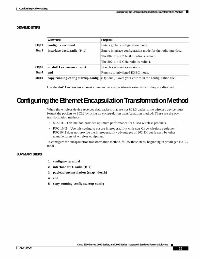
Configuring Radio Settings Configuring the Ethernet Encapsulation Transformation Method
DETAILED STEPS
Use the dot11 extension aironet command to enable Aironet extensions if they are disabled.
Configuring the Ethernet Encapsulation Transformation MethodWhen the wireless device receives data packets that are not 802.3 packets, the wireless device must format the packets to 802.3 by using an encapsulation transformation method. These are the two transformation methods:
• 802.1H—This method provides optimum performance for Cisco wireless products.
• RFC 1042—Use this setting to ensure interoperability with non-Cisco wireless equipment. RFC1042 does not provide the interoperability advantages of 802.1H but is used by other manufacturers of wireless equipment.
To configure the encapsulation transformation method, follow these steps, beginning in privileged EXEC mode.
SUMMARY STEPS
1. configure terminal
2. interface dot11radio {0| 1}
3. payload-encapsulation {snap | dot1h}
4. end
5. copy running-config startup-config
Command Purpose
Step 1 configure terminal Enters global configuration mode.
Step 2 interface dot11radio {0| 1} Enters interface configuration mode for the radio interface.
The 802.11g/n 2.4-GHz radio is radio 0.
The 802.11n 5-GHz radio is radio 1.
Step 3 no dot11 extension aironet Disables Aironet extensions.
Step 4 end Returns to privileged EXEC mode.
Step 5 copy running-config startup-config (Optional) Saves your entries in the configuration file.
25Cisco 3900 Series, 2900 Series, and 1900 Series Integrated Services Routers Software
OL-21850-01

Configuring Radio Settings Enabling and Disabling Public Secure Packet Forwarding
DETAILED STEPS
Enabling and Disabling Public Secure Packet ForwardingPublic Secure Packet Forwarding (PSPF) prevents client devices that are associated to an access point from inadvertently sharing files or communicating with other client devices that are associated to the access point. PSPF provides Internet access to client devices without providing other capabilities of a LAN. This feature is useful for public wireless networks like those installed in airports or on college campuses.
Note To prevent communication between clients associated to different access points, you must set up protected ports on the switch to which the wireless devices are connected. See the “Configuring Protected Ports” section on page 27 for instructions on setting up protected ports.
To enable and disable PSPF using command-line interface (CLI) commands on the wireless device, you use bridge groups. You can find a detailed explanation of bridge groups and instructions for implementing them in this document:
• Cisco IOS Bridging and IBM Networking Configuration Guide, Release 12.2. Click this link to browse to the Configuring Transparent Bridging chapter: http://www.cisco.com/en/US/docs/ios/12_2/ibm/configuration/guide/ bcftb_ps1835_TSD_Products_Configuration_Guide_Chapter.html
PSPF is disabled by default. To enable PSPF, follow these steps, beginning in privileged EXEC mode.
SUMMARY STEPS
1. configure terminal
2. interface dot11radio {0| 1}
3. bridge-group group port-protected
4. end
5. copy running-config startup-config
Command Purpose
Step 1 configure terminal Enters global configuration mode.
Step 2 interface dot11radio {0| 1} Enters interface configuration mode for the radio interface. The 802.11g/n 2.4-GHz radio is radio 0.
The 802.11n 5-GHz radio is radio 1.
Step 3 payload-encapsulation {snap | dot1h}
Sets the encapsulation transformation method to RFC 1042 (snap) or 802.1h (dot1h, the default setting).
Step 4 end Returns to privileged EXEC mode.
Step 5 copy running-config startup-config (Optional) Saves your entries in the configuration file.
26

Configuring Radio Settings Enabling and Disabling Public Secure Packet Forwarding
DETAILED STEPS
Use the no form of the bridge group command to disable PSPF.
Configuring Protected PortsTo prevent communication between client devices that are associated to different access points on your wireless LAN, you must set up protected ports on the switch to which the wireless devices are connected.
To define a port on your switch as a protected port, follow these steps, beginning in privileged EXEC mode.
SUMMARY STEPS
1. configure terminal
2. interface interface-id
3. switchport protected
4. end
5. show interfaces interface-id switchport
6. copy running-config startup-config
DETAILED STEPS
Command Purpose
Step 1 configure terminal Enters global configuration mode.
Step 2 interface dot11radio {0| 1} Enters interface configuration mode for the radio interface. The 802.11g/n 2.4-GHz radio is radio 0.
The 802.11n 5-GHz radio is radio 1.
Step 3 bridge-group group port-protected Enables PSPF.
Step 4 end Returns to privileged EXEC mode.
Step 5 copy running-config startup-config (Optional) Saves your entries in the configuration file.
Command Purpose
Step 1 configure terminal Enters global configuration mode.
Step 2 interface interface-id Enters interface configuration mode. Enter the type and number of the switch port interface to configure, such as wlan-gigabitethernet0.
Step 3 switchport protected Configures the interface to be a protected port.
Step 4 end Returns to privileged EXEC mode.
Step 5 show interfaces interface-id switchport
Verifies your entries.
Step 6 copy running-config startup-config (Optional) Saves your entries in the configuration file.
27Cisco 3900 Series, 2900 Series, and 1900 Series Integrated Services Routers Software
OL-21850-01
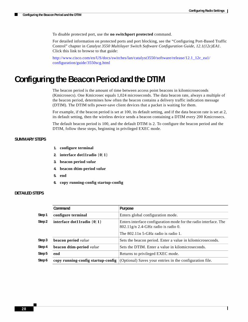
Configuring Radio Settings Configuring the Beacon Period and the DTIM
To disable protected port, use the no switchport protected command.
For detailed information on protected ports and port blocking, see the “Configuring Port-Based Traffic Control” chapter in Catalyst 3550 Multilayer Switch Software Configuration Guide, 12.1(12c)EA1. Click this link to browse to that guide:
http://www.cisco.com/en/US/docs/switches/lan/catalyst3550/software/release/12.1_12c_ea1/ configuration/guide/3550scg.html
Configuring the Beacon Period and the DTIMThe beacon period is the amount of time between access point beacons in kilomicroseconds (Kmicrosecs). One Kmicrosec equals 1,024 microseconds. The data beacon rate, always a multiple of the beacon period, determines how often the beacon contains a delivery traffic indication message (DTIM). The DTIM tells power-save client devices that a packet is waiting for them.
For example, if the beacon period is set at 100, its default setting, and if the data beacon rate is set at 2, its default setting, then the wireless device sends a beacon containing a DTIM every 200 Kmicrosecs.
The default beacon period is 100, and the default DTIM is 2. To configure the beacon period and the DTIM, follow these steps, beginning in privileged EXEC mode.
SUMMARY STEPS
1. configure terminal
2. interface dot11radio {0| 1}
3. beacon period value
4. beacon dtim-period value
5. end
6. copy running-config startup-config
DETAILED STEPS
Command Purpose
Step 1 configure terminal Enters global configuration mode.
Step 2 interface dot11radio {0| 1} Enters interface configuration mode for the radio interface. The 802.11g/n 2.4-GHz radio is radio 0.
The 802.11n 5-GHz radio is radio 1.
Step 3 beacon period value Sets the beacon period. Enter a value in kilomicroseconds.
Step 4 beacon dtim-period value Sets the DTIM. Enter a value in kilomicroseconds.
Step 5 end Returns to privileged EXEC mode.
Step 6 copy running-config startup-config (Optional) Saves your entries in the configuration file.
28

Configuring Radio Settings Configure RTS Threshold and Retries
Configure RTS Threshold and RetriesThe request to send (RTS) threshold determines the packet size at which the wireless device issues an RTS before sending the packet. A low RTS threshold setting can be useful in areas where many client devices are associating with the wireless device, or in areas where the clients are far apart and can detect only the wireless device and not detect each other. You can enter a setting ranging from 0 to 2347 bytes.
Maximum RTS retries is the maximum number of times the wireless device issues an RTS before stopping the attempt to send the packet over the radio. Enter a value from 1 to 128.
The default RTS threshold is 2347 for all access points and bridges, and the default maximum RTS retries setting is 32.
To configure the RTS threshold and maximum RTS retries, follow these steps, beginning in privileged EXEC mode.
SUMMARY STEPS
1. configure terminal
2. interface dot11radio {0| 1}
3. rts threshold value
4. rts retries value
5. end
6. copy running-config startup-config
DETAILED STEPS
Use the no form of the rts command to reset the RTS settings to defaults.
Command Purpose
Step 1 configure terminal Enters global configuration mode.
Step 2 interface dot11radio {0| 1} Enters interface configuration mode for the radio interface. The 2.4-GHz and the 802.11g/n 2.4-GHz radios are radio 0. The 5-GHz and the 802.11n 5-GHz radio is radio 1.
Step 3 rts threshold value Sets the RTS threshold. Enter an RTS threshold from 0 to 2347.
Step 4 rts retries value Sets the maximum RTS retries. Enter a setting from 1 to 128.
Step 5 end Returns to privileged EXEC mode.
Step 6 copy running-config startup-config (Optional) Saves your entries in the configuration file.
29Cisco 3900 Series, 2900 Series, and 1900 Series Integrated Services Routers Software
OL-21850-01

Configuring Radio Settings Configuring the Maximum Data Retries
Configuring the Maximum Data RetriesThe maximum data retries setting determines the number of attempts that the wireless device makes to send a packet before it drops the packet. The default setting is 32.
To configure the maximum data retries, follow these steps, beginning in privileged EXEC mode.
SUMMARY STEPS
1. configure terminal
2. interface dot11radio {0| 1}
3. packet retries value
4. end
5. copy running-config startup-config
DETAILED STEPS
Use the no form of the packet retries command to reset the setting to the default.
Configuring the Fragmentation ThresholdThe fragmentation threshold determines the size at which packets are fragmented (sent as several pieces instead of as one block). Use a low setting in areas where communication is poor or where there is a great deal of radio interference. The default setting is 2346 bytes.
To configure the fragmentation threshold, follow these steps, beginning in privileged EXEC mode.
SUMMARY STEPS
1. configure terminal
2. interface dot11radio {0| 1}
3. fragment-threshold value
4. end
5. copy running-config startup-config
Command Purpose
Step 1 configure terminal Enters global configuration mode.
Step 2 interface dot11radio {0| 1} Enters interface configuration mode for the radio interface. The 802.11g/n 2.4-GHz radio is radio 0.
The 802.11n 5-GHz radio is radio 1.
Step 3 packet retries value Sets the maximum data retries. Enter a setting from 1 to 128.
Step 4 end Returns to privileged EXEC mode.
Step 5 copy running-config startup-config (Optional) Saves your entries in the configuration file.
30
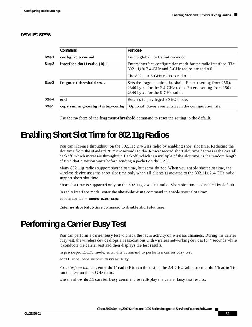
Configuring Radio Settings Enabling Short Slot Time for 802.11g Radios
DETAILED STEPS
Use the no form of the fragment-threshold command to reset the setting to the default.
Enabling Short Slot Time for 802.11g RadiosYou can increase throughput on the 802.11g 2.4-GHz radio by enabling short slot time. Reducing the slot time from the standard 20 microseconds to the 9-microsecond short slot time decreases the overall backoff, which increases throughput. Backoff, which is a multiple of the slot time, is the random length of time that a station waits before sending a packet on the LAN.
Many 802.11g radios support short slot time, but some do not. When you enable short slot time, the wireless device uses the short slot time only when all clients associated to the 802.11g 2.4-GHz radio support short slot time.
Short slot time is supported only on the 802.11g 2.4-GHz radio. Short slot time is disabled by default.
In radio interface mode, enter the short-slot-time command to enable short slot time:
ap(config-if)# short-slot-time
Enter no short-slot-time command to disable short slot time.
Performing a Carrier Busy TestYou can perform a carrier busy test to check the radio activity on wireless channels. During the carrier busy test, the wireless device drops all associations with wireless networking devices for 4 seconds while it conducts the carrier test and then displays the test results.
In privileged EXEC mode, enter this command to perform a carrier busy test:
dot11 interface-number carrier busy
For interface-number, enter dot11radio 0 to run the test on the 2.4-GHz radio, or enter dot11radio 1 to run the test on the 5-GHz radio.
Use the show dot11 carrier busy command to redisplay the carrier busy test results.
Command Purpose
Step 1 configure terminal Enters global configuration mode.
Step 2 interface dot11radio {0| 1} Enters interface configuration mode for the radio interface. The 802.11g/n 2.4-GHz and 5-GHz radios are radio 0.
The 802.11n 5-GHz radio is radio 1.
Step 3 fragment-threshold value Sets the fragmentation threshold. Enter a setting from 256 to 2346 bytes for the 2.4-GHz radio. Enter a setting from 256 to 2346 bytes for the 5-GHz radio.
Step 4 end Returns to privileged EXEC mode.
Step 5 copy running-config startup-config (Optional) Saves your entries in the configuration file.
31Cisco 3900 Series, 2900 Series, and 1900 Series Integrated Services Routers Software
OL-21850-01
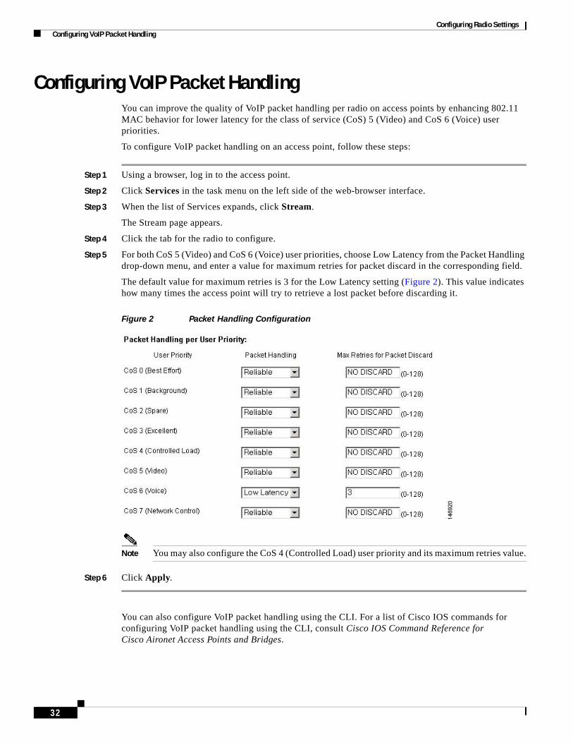
Configuring Radio Settings Configuring VoIP Packet Handling
Configuring VoIP Packet HandlingYou can improve the quality of VoIP packet handling per radio on access points by enhancing 802.11 MAC behavior for lower latency for the class of service (CoS) 5 (Video) and CoS 6 (Voice) user priorities.
To configure VoIP packet handling on an access point, follow these steps:
Step 1 Using a browser, log in to the access point.
Step 2 Click Services in the task menu on the left side of the web-browser interface.
Step 3 When the list of Services expands, click Stream.
The Stream page appears.
Step 4 Click the tab for the radio to configure.
Step 5 For both CoS 5 (Video) and CoS 6 (Voice) user priorities, choose Low Latency from the Packet Handling drop-down menu, and enter a value for maximum retries for packet discard in the corresponding field.
The default value for maximum retries is 3 for the Low Latency setting (Figure 2). This value indicates how many times the access point will try to retrieve a lost packet before discarding it.
Figure 2 Packet Handling Configuration
Note You may also configure the CoS 4 (Controlled Load) user priority and its maximum retries value.
Step 6 Click Apply.
You can also configure VoIP packet handling using the CLI. For a list of Cisco IOS commands for configuring VoIP packet handling using the CLI, consult Cisco IOS Command Reference for Cisco Aironet Access Points and Bridges.
32

Configuring Radio Settings Configuring VoIP Packet Handling
CCDE, CCENT, CCSI, Cisco Eos, Cisco HealthPresence, Cisco IronPort, the Cisco logo, Cisco Nurse Connect, Cisco Pulse, Cisco SensorBase, Cisco StackPower, Cisco StadiumVision, Cisco TelePresence, Cisco Unified Computing System, Cisco WebEx, DCE, Flip Channels, Flip for Good, Flip Mino, Flipshare (Design), Flip Ultra, Flip Video, Flip Video (Design), Instant Broadband, and Welcome to the Human Network are trademarks; Changing the Way We Work, Live, Play, and Learn, Cisco Capital, Cisco Capital (Design), Cisco:Financed (Stylized), Cisco Store, Flip Gift Card, and One Million Acts of Green are service marks; and Access Registrar, Aironet, AllTouch, AsyncOS, Bringing the Meeting To You, Catalyst, CCDA, CCDP, CCIE, CCIP, CCNA, CCNP, CCSP, CCVP, Cisco, the Cisco Certified Internetwork Expert logo, Cisco IOS, Cisco Lumin, Cisco Nexus, Cisco Press, Cisco Systems, Cisco Systems Capital, the Cisco Systems logo, Cisco Unity, Collaboration Without Limitation, Continuum, EtherFast, EtherSwitch, Event Center, Explorer, Follow Me Browsing, GainMaker, iLYNX, IOS, iPhone, IronPort, the IronPort logo, Laser Link, LightStream, Linksys, MeetingPlace, MeetingPlace Chime Sound, MGX, Networkers, Networking Academy, PCNow, PIX, PowerKEY, PowerPanels, PowerTV, PowerTV (Design), PowerVu, Prisma, ProConnect, ROSA, SenderBase, SMARTnet, Spectrum Expert, StackWise, WebEx, and the WebEx logo are registered trademarks of Cisco Systems, Inc. and/or its affiliates in the United States and certain other countries.
All other trademarks mentioned in this document or website are the property of their respective owners. The use of the word partner does not imply a partnership relationship between Cisco and any other company. (0910R)
Any Internet Protocol (IP) addresses used in this document are not intended to be actual addresses. Any examples, command display output, and figures included in the document are shown for illustrative purposes only. Any use of actual IP addresses in illustrative content is unintentional and coincidental. © 2009-2010 Cisco Systems, Inc. All rights reserved.
33Cisco 3900 Series, 2900 Series, and 1900 Series Integrated Services Routers Software
OL-21850-01

Configuring Radio Settings Configuring VoIP Packet Handling
34

Administering the Wireless Device
The following sections describe administration tasks for the wireless device:
Security on the Wireless Device
• Disabling the Mode Button Function, page 2
• Preventing Unauthorized Access to Your Access Point, page 3
• Protecting Access to Privileged EXEC Commands, page 3
• Controlling Access Point Access with RADIUS, page 11
• Controlling Access Point Access with TACACS+, page 16
Administering the Wireless Device
• Administering the Wireless Hardware and Software, page 20
• Resetting the Wireless Device to the Factory Default Configuration, page 20
• Monitoring the Wireless Device, page 21
• Managing the System Time and Date, page 21
• Configuring a System Name and Prompt, page 27
• Creating a Banner, page 30
Configuring Wireless Device Communication
• Configuring Ethernet Speed and Duplex Settings, page 33
• Configuring the Access Point for Wireless Network Management, page 34
• Configuring the Access Point for Local Authentication and Authorization, page 34
• Configuring the Authentication Cache and Profile, page 36
• Configuring the Access Point to Provide DHCP Service, page 38
• Configuring the Access Point for Secure Shell, page 41
• Configuring Client ARP Caching, page 42
• Configuring Multiple VLAN and Rate Limiting for Point-to-Multipoint Bridging, page 43
Americas Headquarters:Cisco Systems, Inc., 170 West Tasman Drive, San Jose, CA 95134-1706 USA
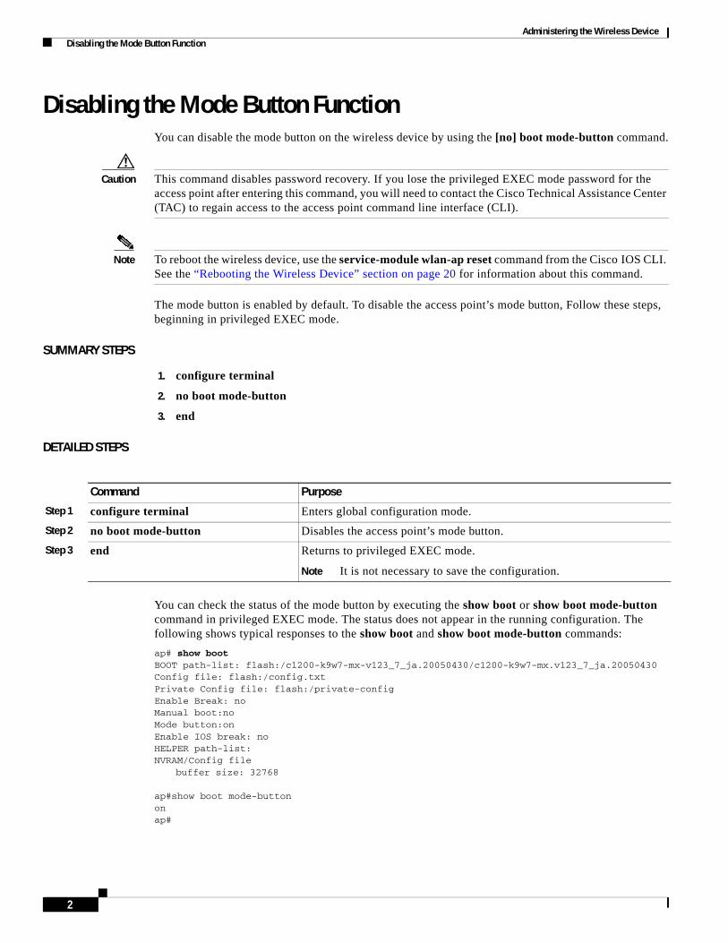
Administering the Wireless Device Disabling the Mode Button Function
Disabling the Mode Button FunctionYou can disable the mode button on the wireless device by using the [no] boot mode-button command.
Caution This command disables password recovery. If you lose the privileged EXEC mode password for the access point after entering this command, you will need to contact the Cisco Technical Assistance Center (TAC) to regain access to the access point command line interface (CLI).
Note To reboot the wireless device, use the service-module wlan-ap reset command from the Cisco IOS CLI. See the “Rebooting the Wireless Device” section on page 20 for information about this command.
The mode button is enabled by default. To disable the access point’s mode button, Follow these steps, beginning in privileged EXEC mode.
SUMMARY STEPS
1. configure terminal
2. no boot mode-button
3. end
DETAILED STEPS
You can check the status of the mode button by executing the show boot or show boot mode-button command in privileged EXEC mode. The status does not appear in the running configuration. The following shows typical responses to the show boot and show boot mode-button commands:
ap# show boot BOOT path-list: flash:/c1200-k9w7-mx-v123_7_ja.20050430/c1200-k9w7-mx.v123_7_ja.20050430 Config file: flash:/config.txt Private Config file: flash:/private-config Enable Break: no Manual boot:no Mode button:on Enable IOS break: no HELPER path-list: NVRAM/Config file
buffer size: 32768 ap#show boot mode-button on ap#
Command Purpose
Step 1 configure terminal Enters global configuration mode.
Step 2 no boot mode-button Disables the access point’s mode button.
Step 3 end Returns to privileged EXEC mode.
Note It is not necessary to save the configuration.
2

Administering the Wireless Device Preventing Unauthorized Access to Your Access Point
Note As long as the privileged EXEC password is known, you can use the boot mode-button command to restore the mode button to normal operation.
Preventing Unauthorized Access to Your Access PointYou can prevent unauthorized users from reconfiguring the wireless device and viewing configuration information. Typically, the network administrators must have access to the wireless device while restricting access to users who connect through a terminal or workstation from within the local network.
To prevent unauthorized access to the wireless device, configure one of these security features:
• Username and password pairs, which are locally stored on the wireless device. These pairs authenticate each user before the user can access the wireless device. You can also assign a specific privilege level (read only or read/write) to each username and password pair. For more information, see the “Configuring Username and Password Pairs” section on page 7. The default username is Cisco, and the default password is Cisco. Usernames and passwords are case sensitive.
Note The characters TAB, ?, $, +, and [ are invalid characters for passwords.
• Username and password pairs are stored centrally in a database on a security server. For more information, see the “Controlling Access Point Access with RADIUS” section on page 11.
Protecting Access to Privileged EXEC CommandsA simple way of providing terminal access control in your network is to use passwords and assign privilege levels. Password protection restricts access to a network or network device. Privilege levels define what commands users can issue after they have logged in to a network device.
Note For complete syntax and usage information for the commands used in this section, see Cisco IOS Security Command Reference for Release 12.4.
This section describes how to control access to the configuration file and privileged EXEC commands. It contains this configuration information:
• Configuring Default Password and Privilege Level, page 4
• Setting or Changing a Static Enable Password, page 4
• Protecting Enable and Enable Secret Passwords with Encryption, page 5
• Configuring Username and Password Pairs, page 7
• Configuring Multiple Privilege Levels, page 8
3OL-21850-01
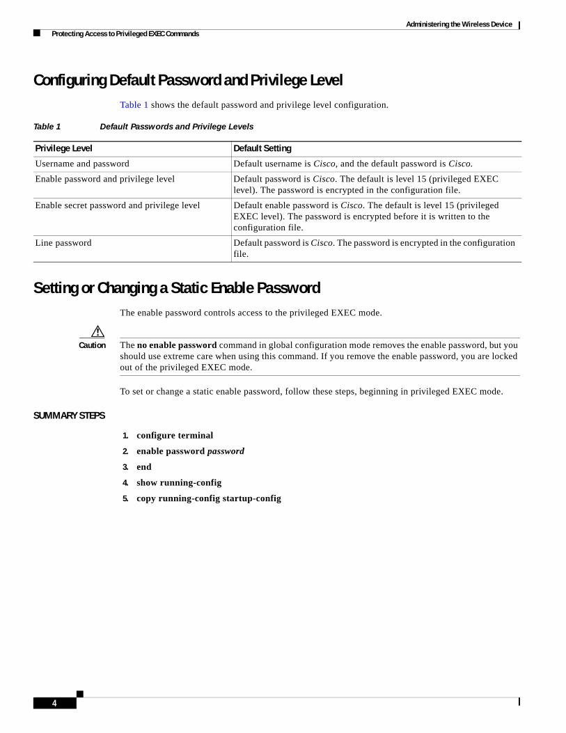
Administering the Wireless Device Protecting Access to Privileged EXEC Commands
Configuring Default Password and Privilege LevelTable 1 shows the default password and privilege level configuration.
Setting or Changing a Static Enable PasswordThe enable password controls access to the privileged EXEC mode.
Caution The no enable password command in global configuration mode removes the enable password, but you should use extreme care when using this command. If you remove the enable password, you are locked out of the privileged EXEC mode.
To set or change a static enable password, follow these steps, beginning in privileged EXEC mode.
SUMMARY STEPS
1. configure terminal
2. enable password password
3. end
4. show running-config
5. copy running-config startup-config
Table 1 Default Passwords and Privilege Levels
Privilege Level Default Setting
Username and password Default username is Cisco, and the default password is Cisco.
Enable password and privilege level Default password is Cisco. The default is level 15 (privileged EXEC level). The password is encrypted in the configuration file.
Enable secret password and privilege level Default enable password is Cisco. The default is level 15 (privileged EXEC level). The password is encrypted before it is written to the configuration file.
Line password Default password is Cisco. The password is encrypted in the configuration file.
4
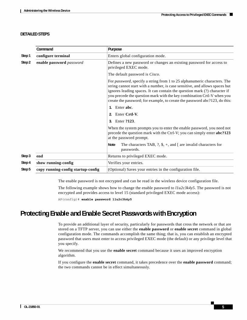
Administering the Wireless Device Protecting Access to Privileged EXEC Commands
DETAILED STEPS
The enable password is not encrypted and can be read in the wireless device configuration file.
The following example shows how to change the enable password to l1u2c3k4y5. The password is not encrypted and provides access to level 15 (standard privileged EXEC mode access):
AP(config)# enable password l1u2c3k4y5
Protecting Enable and Enable Secret Passwords with EncryptionTo provide an additional layer of security, particularly for passwords that cross the network or that are stored on a TFTP server, you can use either the enable password or enable secret command in global configuration mode. The commands accomplish the same thing; that is, you can establish an encrypted password that users must enter to access privileged EXEC mode (the default) or any privilege level that you specify.
We recommend that you use the enable secret command because it uses an improved encryption algorithm.
If you configure the enable secret command, it takes precedence over the enable password command; the two commands cannot be in effect simultaneously.
Command Purpose
Step 1 configure terminal Enters global configuration mode.
Step 2 enable password password Defines a new password or changes an existing password for access to privileged EXEC mode.
The default password is Cisco.
For password, specify a string from 1 to 25 alphanumeric characters. The string cannot start with a number, is case sensitive, and allows spaces but ignores leading spaces. It can contain the question mark (?) character if you precede the question mark with the key combination Crtl-V when you create the password; for example, to create the password abc?123, do this:
1. Enter abc.
2. Enter Crtl-V.
3. Enter ?123.
When the system prompts you to enter the enable password, you need not precede the question mark with the Ctrl-V; you can simply enter abc?123 at the password prompt.
Note The characters TAB, ?, $, +, and [ are invalid characters for passwords.
Step 3 end Returns to privileged EXEC mode.
Step 4 show running-config Verifies your entries.
Step 5 copy running-config startup-config (Optional) Saves your entries in the configuration file.
5OL-21850-01

Administering the Wireless Device Protecting Access to Privileged EXEC Commands
To configure encryption for enable and enable secret passwords, follow these steps, beginning in privileged EXEC mode.
SUMMARY STEPS
1. configure terminal
2. enable password [level level] {password | encryption-type encrypted-password}
or
enable secret [level level] {password | encryption-type encrypted-password}
3. service password-encryption
4. end
5. copy running-config startup-config
DETAILED STEPS
Command Purpose
Step 1 configure terminal Enters global configuration mode.
Step 2 enable password [level level] {password | encryption-type encrypted-password}
or
enable secret [level level] {password | encryption-type encrypted-password}
Defines a new password or changes an existing password for access to privileged EXEC mode.
or
Defines a secret password, which is saved using a nonreversible encryption method.
• (Optional) For level, the range is from 0 to 15. Level 1 is normal user EXEC mode privileges. The default level is 15 (privileged EXEC mode privileges).
• For password, specify a string from 1 to 25 alphanumeric characters. The string cannot start with a number, is case sensitive, and allows spaces but ignores leading spaces. By default, no password is defined.
• (Optional) For encryption-type, only type 5, a Cisco proprietary encryption algorithm, is available. If you specify an encryption type, you must provide an encrypted password—an encrypted password you copy from another access point wireless device configuration.
Note If you specify an encryption type and then enter a clear text password, you cannot reenter privileged EXEC mode. You cannot recover a lost encrypted password by any method.
Step 3 service password-encryption (Optional) Encrypts the password when the password is defined or when the configuration is written.
Encryption prevents the password from being readable in the configuration file.
Step 4 end Returns to privileged EXEC mode.
Step 5 copy running-config startup-config (Optional) Saves your entries in the configuration file.
6

Administering the Wireless Device Protecting Access to Privileged EXEC Commands
If both the enable and enable secret passwords are defined, users must enter the enable secret password.
Use the level keyword to define a password for a specific privilege level. After you specify the level and set a password, give the password only to users who need to have access at this level. Use the privilege level command in global configuration mode to specify commands accessible at various levels. For more information, see the “Configuring Multiple Privilege Levels” section on page 8.
If you enable password encryption, it applies to all passwords, including username passwords, authentication key passwords, the privileged command password, and console and virtual terminal line passwords.
To remove a password and level, use the no enable password [level level] command or the no enable secret [level level] command in global configuration mode. To disable password encryption, use the no service password-encryption command in global configuration mode.
This example shows how to configure the encrypted password $1$FaD0$Xyti5Rkls3LoyxzS8 for privilege level 2:
AP(config)# enable secret level 2 5 $1$FaD0$Xyti5Rkls3LoyxzS8
Configuring Username and Password PairsYou can configure username and password pairs, which are locally stored on the wireless device. These pairs are assigned to lines or interfaces, and they authenticate each user before the user can access the wireless device. If you have defined privilege levels, you can also assign a specific privilege level (with associated rights and privileges) to each username and password pair.
To establish a username-based authentication system that requests a login username and a password, follow these steps, beginning in privileged EXEC mode.
SUMMARY STEPS
1. configure terminal
2. username name [privilege level] {password encryption-type password}
3. login local
4. end
5. show running-config
6. copy running-config startup-config
7OL-21850-01
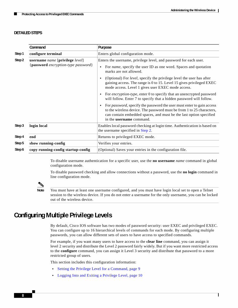
Administering the Wireless Device Protecting Access to Privileged EXEC Commands
DETAILED STEPS
To disable username authentication for a specific user, use the no username name command in global configuration mode.
To disable password checking and allow connections without a password, use the no login command in line configuration mode.
Note You must have at least one username configured, and you must have login local set to open a Telnet session to the wireless device. If you do not enter a username for the only username, you can be locked out of the wireless device.
Configuring Multiple Privilege LevelsBy default, Cisco IOS software has two modes of password security: user EXEC and privileged EXEC. You can configure up to 16 hierarchical levels of commands for each mode. By configuring multiple passwords, you can allow different sets of users to have access to specified commands.
For example, if you want many users to have access to the clear line command, you can assign it level 2 security and distribute the Level 2 password fairly widely. But if you want more restricted access to the configure command, you can assign it Level 3 security and distribute that password to a more restricted group of users.
This section includes this configuration information:
• Setting the Privilege Level for a Command, page 9
• Logging Into and Exiting a Privilege Level, page 10
Command Purpose
Step 1 configure terminal Enters global configuration mode.
Step 2 username name [privilege level] {password encryption-type password}
Enters the username, privilege level, and password for each user.
• For name, specify the user ID as one word. Spaces and quotation marks are not allowed.
• (Optional) For level, specify the privilege level the user has after gaining access. The range is 0 to 15. Level 15 gives privileged EXEC mode access. Level 1 gives user EXEC mode access.
• For encryption-type, enter 0 to specify that an unencrypted password will follow. Enter 7 to specify that a hidden password will follow.
• For password, specify the password the user must enter to gain access to the wireless device. The password must be from 1 to 25 characters, can contain embedded spaces, and must be the last option specified in the username command.
Step 3 login local Enables local password checking at login time. Authentication is based on the username specified in Step 2.
Step 4 end Returns to privileged EXEC mode.
Step 5 show running-config Verifies your entries.
Step 6 copy running-config startup-config (Optional) Saves your entries in the configuration file.
8
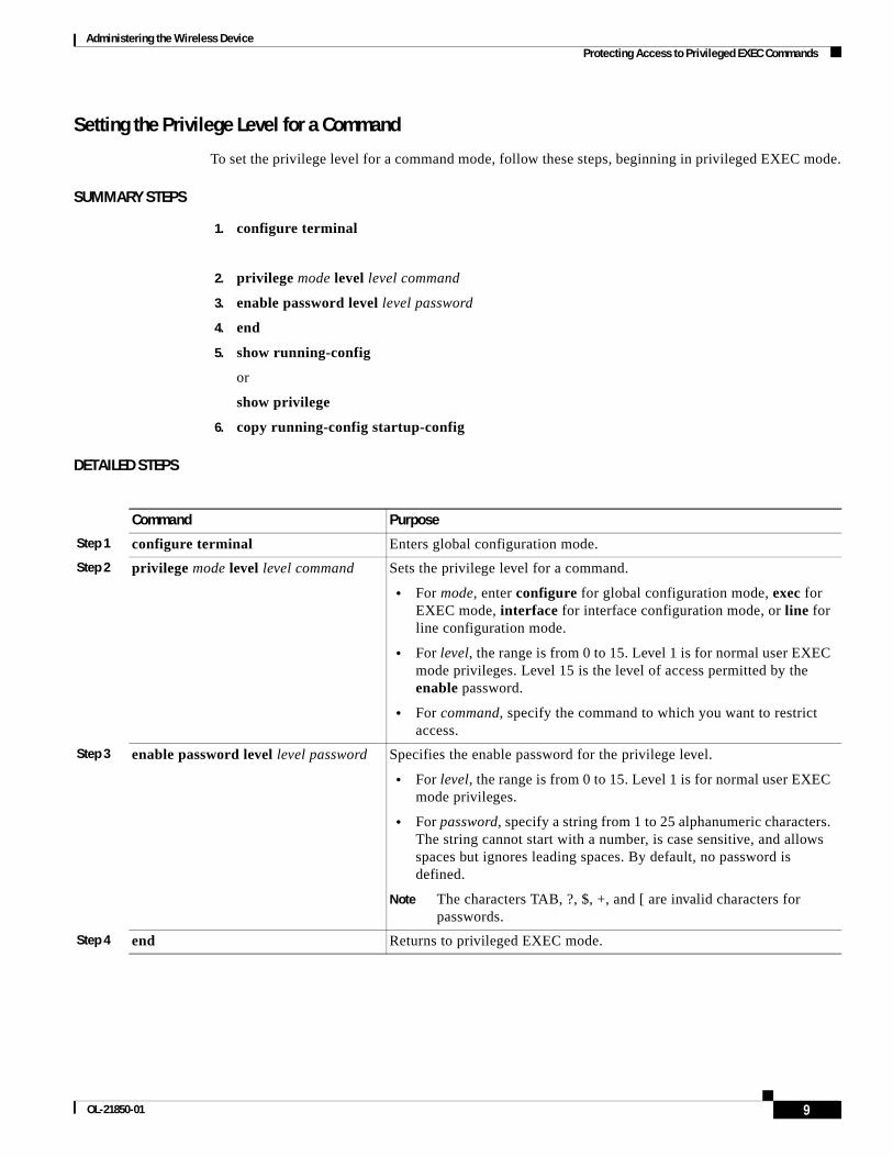
Administering the Wireless Device Protecting Access to Privileged EXEC Commands
Setting the Privilege Level for a Command
To set the privilege level for a command mode, follow these steps, beginning in privileged EXEC mode.
SUMMARY STEPS
1. configure terminal
2. privilege mode level level command
3. enable password level level password
4. end
5. show running-config
or
show privilege
6. copy running-config startup-config
DETAILED STEPS
Command Purpose
Step 1 configure terminal Enters global configuration mode.
Step 2 privilege mode level level command Sets the privilege level for a command.
• For mode, enter configure for global configuration mode, exec for EXEC mode, interface for interface configuration mode, or line for line configuration mode.
• For level, the range is from 0 to 15. Level 1 is for normal user EXEC mode privileges. Level 15 is the level of access permitted by the enable password.
• For command, specify the command to which you want to restrict access.
Step 3 enable password level level password Specifies the enable password for the privilege level.
• For level, the range is from 0 to 15. Level 1 is for normal user EXEC mode privileges.
• For password, specify a string from 1 to 25 alphanumeric characters. The string cannot start with a number, is case sensitive, and allows spaces but ignores leading spaces. By default, no password is defined.
Note The characters TAB, ?, $, +, and [ are invalid characters for passwords.
Step 4 end Returns to privileged EXEC mode.
9OL-21850-01
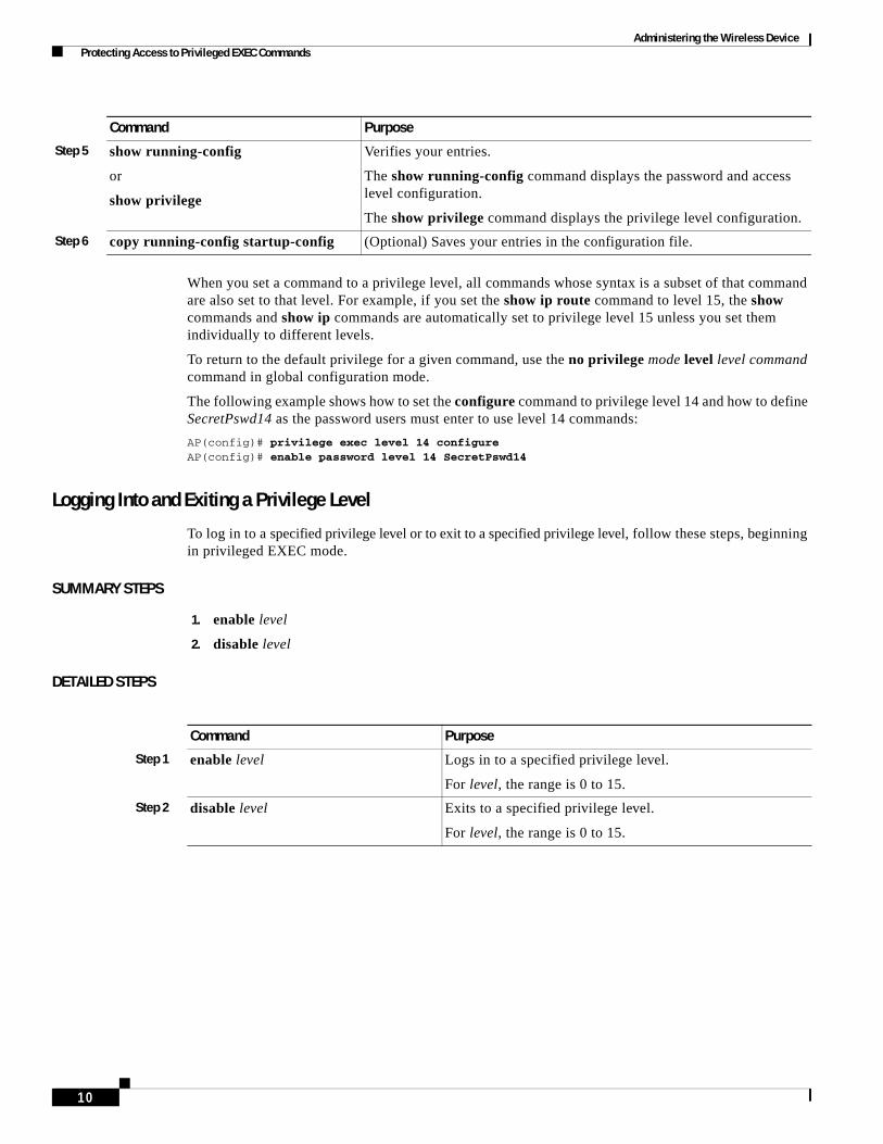
Administering the Wireless Device Protecting Access to Privileged EXEC Commands
When you set a command to a privilege level, all commands whose syntax is a subset of that command are also set to that level. For example, if you set the show ip route command to level 15, the show commands and show ip commands are automatically set to privilege level 15 unless you set them individually to different levels.
To return to the default privilege for a given command, use the no privilege mode level level command command in global configuration mode.
The following example shows how to set the configure command to privilege level 14 and how to define SecretPswd14 as the password users must enter to use level 14 commands:
AP(config)# privilege exec level 14 configureAP(config)# enable password level 14 SecretPswd14
Logging Into and Exiting a Privilege Level
To log in to a specified privilege level or to exit to a specified privilege level, follow these steps, beginning in privileged EXEC mode.
SUMMARY STEPS
1. enable level
2. disable level
DETAILED STEPS
Step 5 show running-config
or
show privilege
Verifies your entries.
The show running-config command displays the password and access level configuration.
The show privilege command displays the privilege level configuration.
Step 6 copy running-config startup-config (Optional) Saves your entries in the configuration file.
Command Purpose
Command Purpose
Step 1 enable level Logs in to a specified privilege level.
For level, the range is 0 to 15.
Step 2 disable level Exits to a specified privilege level.
For level, the range is 0 to 15.
10

Administering the Wireless Device Controlling Access Point Access with RADIUS
Controlling Access Point Access with RADIUS This section describes how to control administrator access to the wireless device by using Remote Authentication Dial-In User Service (RADIUS). For complete instructions on configuring the wireless device to support RADIUS, see the “Configuring Radius and TACACS+ Servers” chapter in Cisco IOS Software Configuration Guide for Cisco Aironet Access Points.
RADIUS provides detailed accounting information and flexible administrative control over authentication and authorization processes. RADIUS is facilitated through authentication, authorization, and accounting (AAA) and can be enabled only through AAA commands.
Note For complete syntax and usage information for the commands used in this section, see Cisco IOS Security Command Reference.
These sections describe RADIUS configuration:
• Default RADIUS Configuration, page 11
• Configuring RADIUS Login Authentication, page 11 (required)
• Defining AAA Server Groups, page 13 (optional)
• Configuring RADIUS Authorization for User Privileged Access and Network Services, page 15 (optional)
• Displaying the RADIUS Configuration, page 16
Default RADIUS ConfigurationRADIUS and AAA are disabled by default.
To prevent a lapse in security, you cannot configure RADIUS through a network management application. When enabled, RADIUS can authenticate users who are accessing the wireless device through the command-line interface (CLI).
Configuring RADIUS Login AuthenticationTo configure AAA authentication, you define a named list of authentication methods and then apply the list to various interfaces. The method list defines the types of authentication to be performed and the sequence in which they are performed; it must be applied to a specific interface before any defined authentication methods are performed. The only exception is the default method list (which is named default). The default method list is automatically applied to all interfaces except those that have a named method list explicitly defined.
A method list describes the sequence and authentication methods to be used to authenticate a user. You can designate one or more security protocols for authentication, thus ensuring a backup system for authentication in case the initial method fails. The software uses the first method listed to authenticate users. If that method fails to respond, the software selects the next authentication method in the method list. This process continues until there is successful communication with a listed authentication method or until all defined methods are exhausted. If authentication fails at any point in this cycle—that is, the security server or local username database responds by denying the user access—the authentication process stops, and no other authentication methods are attempted.
11OL-21850-01
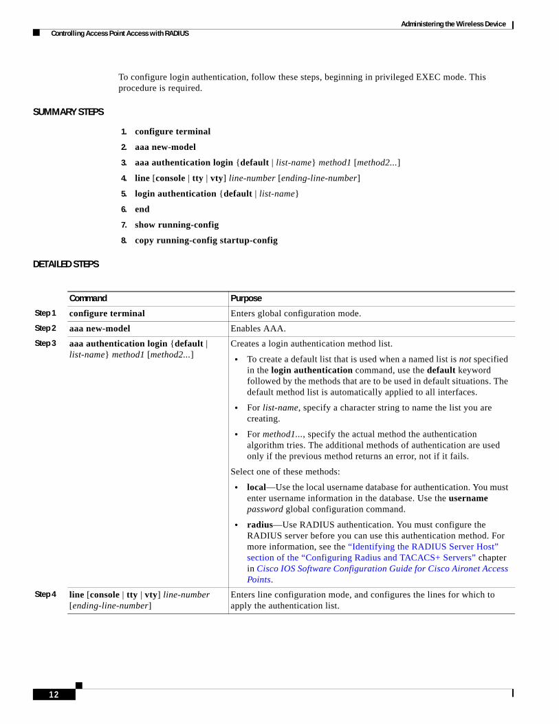
Administering the Wireless Device Controlling Access Point Access with RADIUS
To configure login authentication, follow these steps, beginning in privileged EXEC mode. This procedure is required.
SUMMARY STEPS
1. configure terminal
2. aaa new-model
3. aaa authentication login {default | list-name} method1 [method2...]
4. line [console | tty | vty] line-number [ending-line-number]
5. login authentication {default | list-name}
6. end
7. show running-config
8. copy running-config startup-config
DETAILED STEPS
Command Purpose
Step 1 configure terminal Enters global configuration mode.
Step 2 aaa new-model Enables AAA.
Step 3 aaa authentication login {default | list-name} method1 [method2...]
Creates a login authentication method list.
• To create a default list that is used when a named list is not specified in the login authentication command, use the default keyword followed by the methods that are to be used in default situations. The default method list is automatically applied to all interfaces.
• For list-name, specify a character string to name the list you are creating.
• For method1..., specify the actual method the authentication algorithm tries. The additional methods of authentication are used only if the previous method returns an error, not if it fails.
Select one of these methods:
• local—Use the local username database for authentication. You must enter username information in the database. Use the username password global configuration command.
• radius—Use RADIUS authentication. You must configure the RADIUS server before you can use this authentication method. For more information, see the “Identifying the RADIUS Server Host” section of the “Configuring Radius and TACACS+ Servers” chapter in Cisco IOS Software Configuration Guide for Cisco Aironet Access Points.
Step 4 line [console | tty | vty] line-number [ending-line-number]
Enters line configuration mode, and configures the lines for which to apply the authentication list.
12

Administering the Wireless Device Controlling Access Point Access with RADIUS
To disable AAA, use the no aaa new-model command in global command mode. To disable AAA authentication, use the no aaa authentication login {default | list-name} method1 [method2...] command in global command mode. To either disable RADIUS authentication for logins or to return to the default value, use the no login authentication {default | list-name} command in line configuration mode.
Defining AAA Server GroupsYou can configure the wireless device to use AAA server groups to group existing server hosts for authentication. You select a subset of the configured server hosts and use them for a particular service. The server group is used with a global server-host list, which lists the IP addresses of the selected server hosts.
Server groups can also include multiple host entries for the same server if each entry has a unique identifier (the combination of the IP address and UDP port number), allowing different ports to be individually defined as RADIUS hosts providing a specific AAA service. If you configure two different host entries on the same RADIUS server for the same service (such as accounting), the second configured host entry acts as a failover backup to the first one.
You use the server group server configuration command to associate a particular server with a defined group server. You can either identify the server by its IP address or identify multiple host instances or entries by using the optional auth-port and acct-port keywords.
To define the AAA server group and associate a particular RADIUS server with it, follow these steps, beginning in privileged EXEC mode.
SUMMARY STEPS
1. configure terminal
2. aaa new-model
3. radius-server host {hostname | ip-address} [auth-port port-number] [acct-port port-number] [timeout seconds] [retransmit retries] [key string]
4. aaa group server radius group-name
5. server ip-address
6. end
7. show running-config
Step 5 login authentication {default | list-name}
Applies the authentication list to a line or set of lines.
• If you specify default, use the default list that you created with the aaa authentication login command.
• For list-name, specify the list that you created with the aaa authentication login command.
Step 6 end Returns to privileged EXEC mode.
Step 7 show running-config Verifies your entries.
Step 8 copy running-config startup-config (Optional) Saves your entries in the configuration file.
Command Purpose
13OL-21850-01
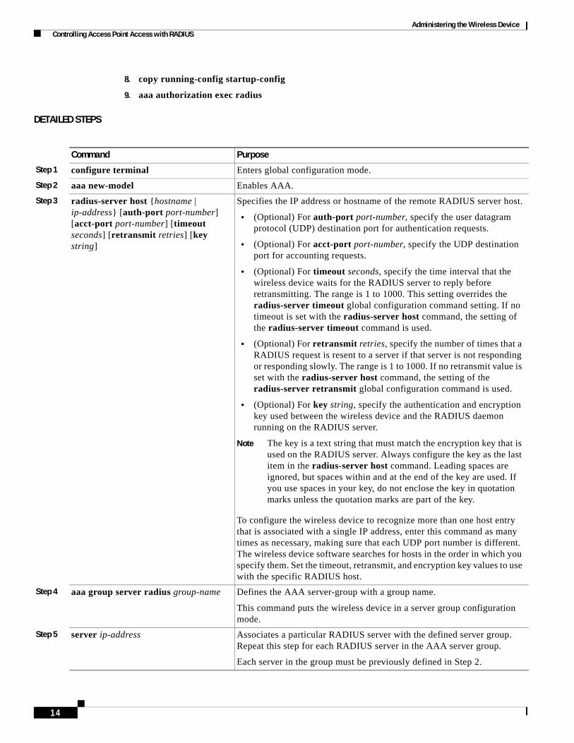
Administering the Wireless Device Controlling Access Point Access with RADIUS
8. copy running-config startup-config
9. aaa authorization exec radius
DETAILED STEPS
Command Purpose
Step 1 configure terminal Enters global configuration mode.
Step 2 aaa new-model Enables AAA.
Step 3 radius-server host {hostname | ip-address} [auth-port port-number] [acct-port port-number] [timeout seconds] [retransmit retries] [key string]
Specifies the IP address or hostname of the remote RADIUS server host.
• (Optional) For auth-port port-number, specify the user datagram protocol (UDP) destination port for authentication requests.
• (Optional) For acct-port port-number, specify the UDP destination port for accounting requests.
• (Optional) For timeout seconds, specify the time interval that the wireless device waits for the RADIUS server to reply before retransmitting. The range is 1 to 1000. This setting overrides the radius-server timeout global configuration command setting. If no timeout is set with the radius-server host command, the setting of the radius-server timeout command is used.
• (Optional) For retransmit retries, specify the number of times that a RADIUS request is resent to a server if that server is not responding or responding slowly. The range is 1 to 1000. If no retransmit value is set with the radius-server host command, the setting of the radius-server retransmit global configuration command is used.
• (Optional) For key string, specify the authentication and encryption key used between the wireless device and the RADIUS daemon running on the RADIUS server.
Note The key is a text string that must match the encryption key that is used on the RADIUS server. Always configure the key as the last item in the radius-server host command. Leading spaces are ignored, but spaces within and at the end of the key are used. If you use spaces in your key, do not enclose the key in quotation marks unless the quotation marks are part of the key.
To configure the wireless device to recognize more than one host entry that is associated with a single IP address, enter this command as many times as necessary, making sure that each UDP port number is different. The wireless device software searches for hosts in the order in which you specify them. Set the timeout, retransmit, and encryption key values to use with the specific RADIUS host.
Step 4 aaa group server radius group-name Defines the AAA server-group with a group name.
This command puts the wireless device in a server group configuration mode.
Step 5 server ip-address Associates a particular RADIUS server with the defined server group. Repeat this step for each RADIUS server in the AAA server group.
Each server in the group must be previously defined in Step 2.
14
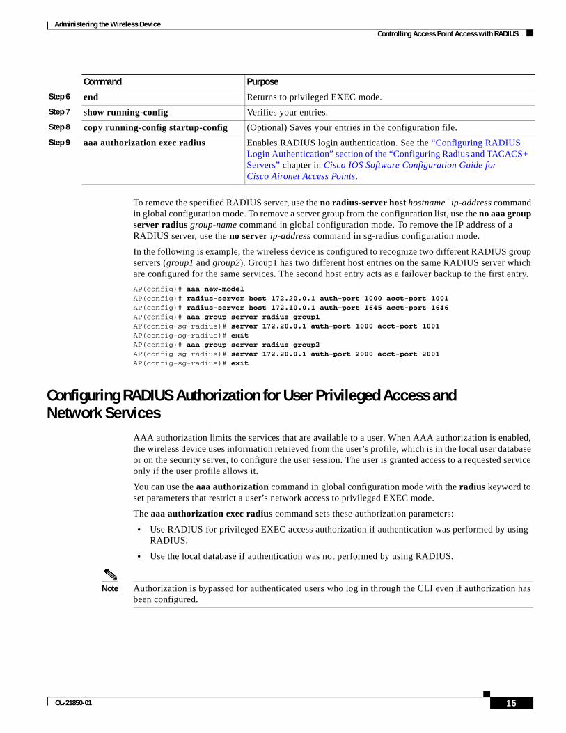
Administering the Wireless Device Controlling Access Point Access with RADIUS
To remove the specified RADIUS server, use the no radius-server host hostname | ip-address command in global configuration mode. To remove a server group from the configuration list, use the no aaa group server radius group-name command in global configuration mode. To remove the IP address of a RADIUS server, use the no server ip-address command in sg-radius configuration mode.
In the following is example, the wireless device is configured to recognize two different RADIUS group servers (group1 and group2). Group1 has two different host entries on the same RADIUS server which are configured for the same services. The second host entry acts as a failover backup to the first entry.
AP(config)# aaa new-modelAP(config)# radius-server host 172.20.0.1 auth-port 1000 acct-port 1001AP(config)# radius-server host 172.10.0.1 auth-port 1645 acct-port 1646AP(config)# aaa group server radius group1AP(config-sg-radius)# server 172.20.0.1 auth-port 1000 acct-port 1001AP(config-sg-radius)# exitAP(config)# aaa group server radius group2AP(config-sg-radius)# server 172.20.0.1 auth-port 2000 acct-port 2001AP(config-sg-radius)# exit
Configuring RADIUS Authorization for User Privileged Access and Network Services
AAA authorization limits the services that are available to a user. When AAA authorization is enabled, the wireless device uses information retrieved from the user’s profile, which is in the local user database or on the security server, to configure the user session. The user is granted access to a requested service only if the user profile allows it.
You can use the aaa authorization command in global configuration mode with the radius keyword to set parameters that restrict a user’s network access to privileged EXEC mode.
The aaa authorization exec radius command sets these authorization parameters:
• Use RADIUS for privileged EXEC access authorization if authentication was performed by using RADIUS.
• Use the local database if authentication was not performed by using RADIUS.
Note Authorization is bypassed for authenticated users who log in through the CLI even if authorization has been configured.
Step 6 end Returns to privileged EXEC mode.
Step 7 show running-config Verifies your entries.
Step 8 copy running-config startup-config (Optional) Saves your entries in the configuration file.
Step 9 aaa authorization exec radius Enables RADIUS login authentication. See the “Configuring RADIUS Login Authentication” section of the “Configuring Radius and TACACS+ Servers” chapter in Cisco IOS Software Configuration Guide for Cisco Aironet Access Points.
Command Purpose
15OL-21850-01

Administering the Wireless Device Controlling Access Point Access with TACACS+
To specify RADIUS authorization for privileged EXEC access and network services, follow these steps, beginning in privileged EXEC mode.
SUMMARY STEPS
1. configure terminal
2. aaa authorization network radius
3. aaa authorization exec radius
4. end
5. show running-config
6. copy running-config startup-config
DETAILED STEPS
To disable authorization, use the no aaa authorization {network | exec} method1 command in global configuration mode.
Displaying the RADIUS ConfigurationTo display the RADIUS configuration, use the show running-config command in privileged EXEC mode.
Controlling Access Point Access with TACACS+ This section describes how to control administrator access to the wireless device using Terminal Access Controller Access Control System Plus (TACACS+). For complete instructions on configuring the wireless device to support TACACS+, see the “Configuring Radius and TACACS+ Servers” chapter in Cisco IOS Software Configuration Guide for Cisco Aironet Access Points.
TACACS+ provides detailed accounting information and flexible administrative control over authentication and authorization processes. TACACS+ is facilitated through AAA and can be enabled only through AAA commands.
Command Purpose
Step 1 configure terminal Enters global configuration mode.
Step 2 aaa authorization network radius Configures the wireless device for user RADIUS authorization for all network-related service requests.
Step 3 aaa authorization exec radius Configures the wireless device for user RADIUS authorization to determine whether the user has privileged EXEC access.
The exec keyword might return user profile information (such as autocommand information).
Step 4 end Returns to privileged EXEC mode.
Step 5 show running-config Verifies your entries.
Step 6 copy running-config startup-config (Optional) Saves your entries in the configuration file.
16

Administering the Wireless Device Controlling Access Point Access with TACACS+
Note For complete syntax and usage information for the commands used in this section, see Cisco IOS Security Command Reference.
These sections describe TACACS+ configuration:
• Default TACACS+ Configuration, page 17
• Configuring TACACS+ Login Authentication, page 17
• Configuring TACACS+ Authorization for Privileged EXEC Access and Network Services, page 19
• Displaying the TACACS+ Configuration, page 20
Default TACACS+ ConfigurationTACACS+ and AAA are disabled by default.
To prevent a lapse in security, you cannot configure TACACS+ through a network management application.When enabled, TACACS+ can authenticate administrators who are accessing the wireless device through the CLI.
Configuring TACACS+ Login AuthenticationTo configure AAA authentication, you define a named list of authentication methods and then apply the list to various interfaces. The method list defines the types of authentication to be performed and the sequence in which they are performed; it must be applied to a specific interface before any defined authentication methods are performed. The only exception is the default method list (which is named default). The default method list is automatically applied to all interfaces except those that have a named method list explicitly defined.
A method list describes the sequence and authentication methods to be used to authenticate a user. You can designate one or more security protocols for authentication, thus ensuring a backup system for authentication in case the initial method fails. The software uses the first method listed to authenticate users. If that method fails to respond, the software selects the next authentication method in the method list. This process continues until there is successful communication with a listed authentication method or until all defined methods are exhausted. If authentication fails at any point in this cycle—that is, the security server or local username database responds by denying the user access—the authentication process stops, and no other authentication methods are attempted.
To configure login authentication, follow these steps, beginning in privileged EXEC mode. This procedure is required.
SUMMARY STEPS
1. configure terminal
2. aaa new-model
3. aaa authentication login {default | list-name} method1 [method2...]
4. line [console | tty | vty] line-number [ending-line-number]
5. login authentication {default | list-name}
6. end
17OL-21850-01
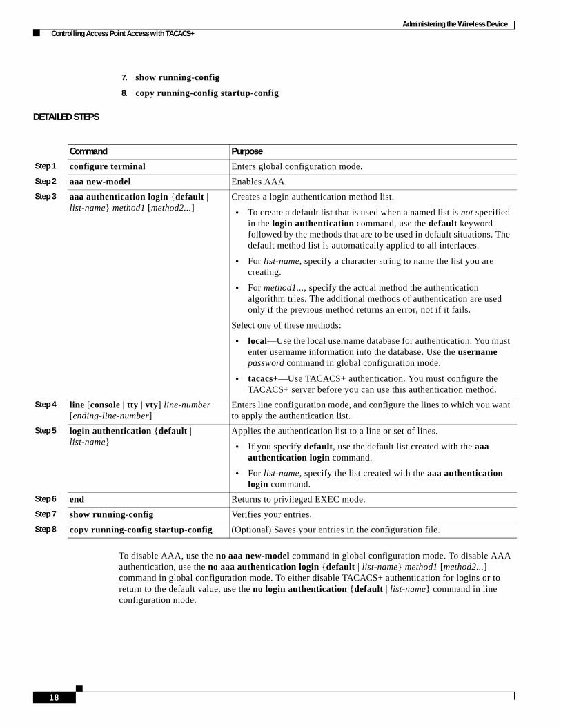
Administering the Wireless Device Controlling Access Point Access with TACACS+
7. show running-config
8. copy running-config startup-config
DETAILED STEPS
To disable AAA, use the no aaa new-model command in global configuration mode. To disable AAA authentication, use the no aaa authentication login {default | list-name} method1 [method2...] command in global configuration mode. To either disable TACACS+ authentication for logins or to return to the default value, use the no login authentication {default | list-name} command in line configuration mode.
Command Purpose
Step 1 configure terminal Enters global configuration mode.
Step 2 aaa new-model Enables AAA.
Step 3 aaa authentication login {default | list-name} method1 [method2...]
Creates a login authentication method list.
• To create a default list that is used when a named list is not specified in the login authentication command, use the default keyword followed by the methods that are to be used in default situations. The default method list is automatically applied to all interfaces.
• For list-name, specify a character string to name the list you are creating.
• For method1..., specify the actual method the authentication algorithm tries. The additional methods of authentication are used only if the previous method returns an error, not if it fails.
Select one of these methods:
• local—Use the local username database for authentication. You must enter username information into the database. Use the username password command in global configuration mode.
• tacacs+—Use TACACS+ authentication. You must configure the TACACS+ server before you can use this authentication method.
Step 4 line [console | tty | vty] line-number [ending-line-number]
Enters line configuration mode, and configure the lines to which you want to apply the authentication list.
Step 5 login authentication {default | list-name}
Applies the authentication list to a line or set of lines.
• If you specify default, use the default list created with the aaa authentication login command.
• For list-name, specify the list created with the aaa authentication login command.
Step 6 end Returns to privileged EXEC mode.
Step 7 show running-config Verifies your entries.
Step 8 copy running-config startup-config (Optional) Saves your entries in the configuration file.
18
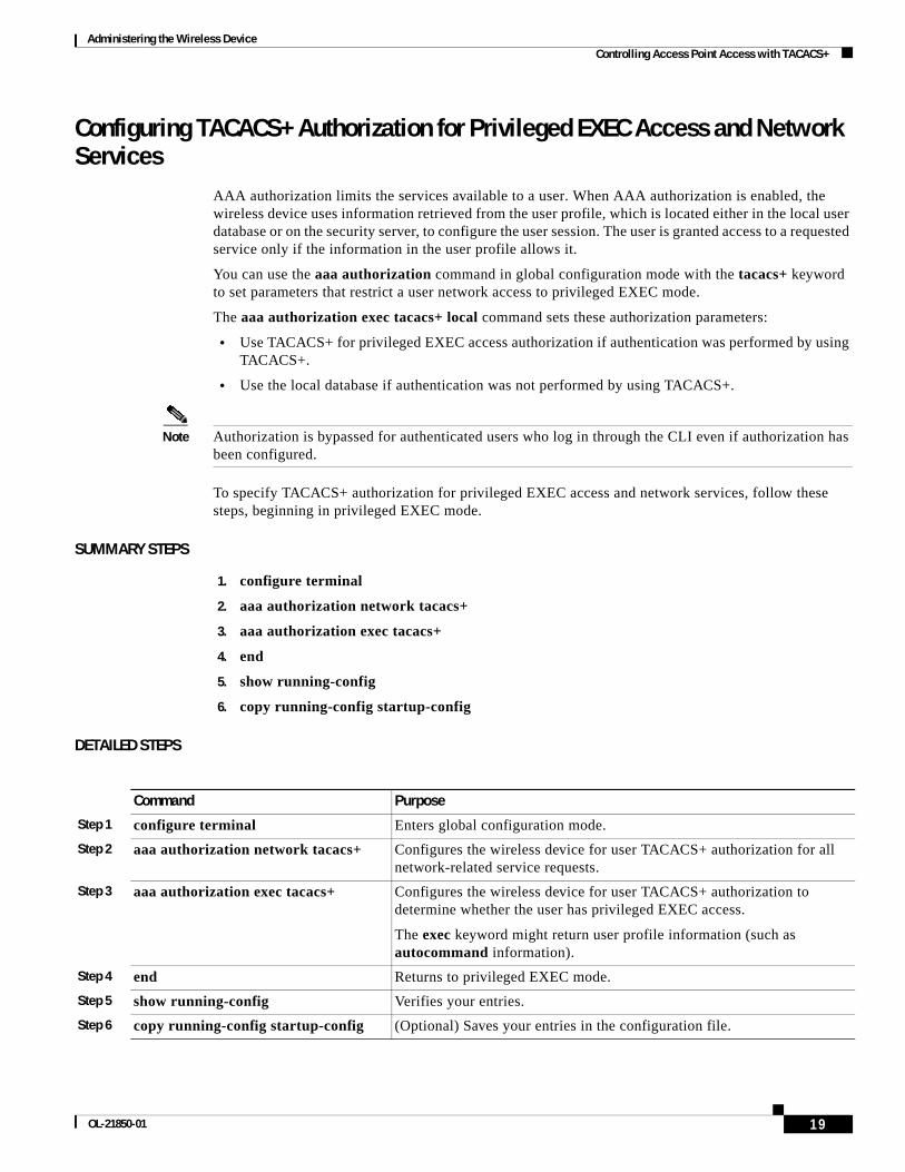
Administering the Wireless Device Controlling Access Point Access with TACACS+
Configuring TACACS+ Authorization for Privileged EXEC Access and Network Services
AAA authorization limits the services available to a user. When AAA authorization is enabled, the wireless device uses information retrieved from the user profile, which is located either in the local user database or on the security server, to configure the user session. The user is granted access to a requested service only if the information in the user profile allows it.
You can use the aaa authorization command in global configuration mode with the tacacs+ keyword to set parameters that restrict a user network access to privileged EXEC mode.
The aaa authorization exec tacacs+ local command sets these authorization parameters:
• Use TACACS+ for privileged EXEC access authorization if authentication was performed by using TACACS+.
• Use the local database if authentication was not performed by using TACACS+.
Note Authorization is bypassed for authenticated users who log in through the CLI even if authorization has been configured.
To specify TACACS+ authorization for privileged EXEC access and network services, follow these steps, beginning in privileged EXEC mode.
SUMMARY STEPS
1. configure terminal
2. aaa authorization network tacacs+
3. aaa authorization exec tacacs+
4. end
5. show running-config
6. copy running-config startup-config
DETAILED STEPS
Command Purpose
Step 1 configure terminal Enters global configuration mode.
Step 2 aaa authorization network tacacs+ Configures the wireless device for user TACACS+ authorization for all network-related service requests.
Step 3 aaa authorization exec tacacs+ Configures the wireless device for user TACACS+ authorization to determine whether the user has privileged EXEC access.
The exec keyword might return user profile information (such as autocommand information).
Step 4 end Returns to privileged EXEC mode.
Step 5 show running-config Verifies your entries.
Step 6 copy running-config startup-config (Optional) Saves your entries in the configuration file.
19OL-21850-01

Administering the Wireless Device Administering the Wireless Hardware and Software
To disable authorization, use the no aaa authorization {network | exec} method1 command in global configuration mode.
Displaying the TACACS+ ConfigurationTo display TACACS+ server statistics, use the show tacacs command in privileged EXEC mode.
Administering the Wireless Hardware and SoftwareThis section provides instructions for performing the following tasks:
• Resetting the Wireless Device to the Factory Default Configuration, page 20
• Rebooting the Wireless Device, page 20
• Monitoring the Wireless Device, page 21
Resetting the Wireless Device to the Factory Default ConfigurationTo reset the wireless device hardware and software to its factory default configuration, use the service-module wlan-ap0 reset default-config command in the router’s Cisco IOS privileged EXEC mode.
Caution Because you may lose data, use only the service-module wlan-ap0 reset command to recover from a shutdown or failed state.
Rebooting the Wireless DeviceTo perform a graceful shutdown and reboot the wireless device, use the service-module wlan-ap0 reload command in the router’s Cisco IOS privileged EXEC mode. At the confirmation prompt, press Enter to confirm the action, or enter n to cancel.
When running in autonomous mode, the reload command saves the configuration before rebooting. If the attempt is unsuccessful, the following message displays:
Failed to save service module configuration.
When running in Lightweight Access Point Protocol (LWAPP) mode, the reload function is typically handled by the wireless LAN controller (WLC). If you enter the service-module wlan-ap0 reload command, you are prompted with the following message:
The AP is in LWAPP mode. Reload is normally handled by WLC controller. Still want to proceed? [yes]
20

Administering the Wireless Device Managing the System Time and Date
Monitoring the Wireless DeviceThis section provides commands for monitoring hardware on the router.
• Displaying Wireless Device Statistics, page 21
• Displaying Wireless Device Status, page 21
Displaying Wireless Device Statistics
Use the service-module wlan-ap0 statistics command in privileged EXEC mode to display wireless device statistics. The following is sample output for the command:
CLI reset count = 0 CLI reload count = 1 Registration request timeout reset count = 0 Error recovery timeout reset count = 0 Module registration count = 10
The last IOS initiated event was a cli reload at *04:27:32.041 UTC Fri Mar 8 2007
Displaying Wireless Device Status
Use the service-module wlan-ap0 status command in privileged EXEC mode to display the status of the wireless device and its configuration information. The following is sample output for the command:
Service Module is Cisco wlan-ap0 Service Module supports session via TTY line 2 Service Module is in Steady state Service Module reset on error is disabled Getting status from the Service Module, please wait.. Image path = flash:c8xx_19xx_ap-k9w7-mx.acregr/c8xx_19xx_ap-k9w7-mx.acre gr System uptime = 0 days, 4 hours, 28 minutes, 5 secondsRouter#d was introduced for embedded wireless LAN access points on Integrated Services Routers.
Managing the System Time and DateYou can manage the system time and date on the wireless device automatically, by using the Simple Network Time Protocol (SNTP), or manually, by setting the time and date on the wireless device.
Note For complete syntax and usage information for the commands used in this section, see Cisco IOS Configuration Fundamentals Command Reference for Release 12.4.
This section provides the following configuration information:
• Understanding Simple Network Time Protocol, page 22
• Configuring SNTP, page 22
• Configuring Time and Date Manually, page 22
21OL-21850-01

Administering the Wireless Device Managing the System Time and Date
Understanding Simple Network Time ProtocolSimple Network Time Protocol (SNTP) is a simplified, client-only version of NTP. SNTP can only receive the time from NTP servers; it cannot provide time services to other systems. SNTP typically provides time within 100 milliseconds of the accurate time, but it does not provide the complex filtering and statistical mechanisms of NTP.
You can configure SNTP to request and accept packets from configured servers or to accept NTP broadcast packets from any source. When multiple sources are sending NTP packets, the server with the best stratum is selected. Click this URL for more information on NTP and strata:
http://www.cisco.com/en/US/docs/ios/12_1/configfun/configuration/guide/fcd303.html#wp1001075
If multiple servers are at the same stratum, a configured server is preferred rather than a broadcast server. If multiple servers pass both tests, the first one to send a time packet is selected. SNTP chooses a new server only if the client stops receiving packets from the currently selected server, or if (according to the above criteria) SNTP discovers a better server.
Configuring SNTPSNTP is disabled by default. To enable SNTP on the access point, use one or both of the commands listed in Table 2 in global configuration mode.
Enter the sntp server command once for each NTP server. The NTP servers must be configured to respond to the SNTP messages from the access point.
If you enter both the sntp server command and the sntp broadcast client command, the access point accepts time from a broadcast server but prefers time from a configured server, if the strata are equal. To display information about SNTP, use the show sntp EXEC command.
Configuring Time and Date ManuallyIf no other source of time is available, you can manually configure the time and date after restarting the system. The time remains accurate until the next system restart. We recommend that you use manual configuration only as a last resort. If you have an outside source to which the wireless device can synchronize, you do not need to manually set the system clock.
This section contains the following configuration information:
• Setting the System Clock, page 23
• Displaying the Time and Date Configuration, page 23
• Configuring the Time Zone, page 24
• Configuring Summer Time (Daylight Saving Time), page 24
Table 2 SNTP Commands
Command Purpose
sntp server {address | hostname} [version number]
Configures SNTP to request NTP packets from an NTP server.
sntp broadcast client Configures SNTP to accept NTP packets from any NTP broadcast server.
22
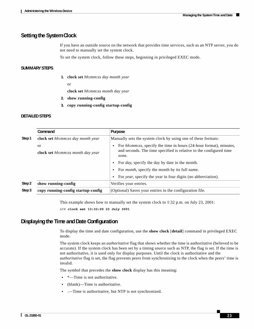
Administering the Wireless Device Managing the System Time and Date
Setting the System Clock
If you have an outside source on the network that provides time services, such as an NTP server, you do not need to manually set the system clock.
To set the system clock, follow these steps, beginning in privileged EXEC mode.
SUMMARY STEPS
1. clock set hh:mm:ss day month year
or
clock set hh:mm:ss month day year
2. show running-config
3. copy running-config startup-config
DETAILED STEPS
This example shows how to manually set the system clock to 1:32 p.m. on July 23, 2001:
AP# clock set 13:32:00 23 July 2001
Displaying the Time and Date Configuration
To display the time and date configuration, use the show clock [detail] command in privileged EXEC mode.
The system clock keeps an authoritative flag that shows whether the time is authoritative (believed to be accurate). If the system clock has been set by a timing source such as NTP, the flag is set. If the time is not authoritative, it is used only for display purposes. Until the clock is authoritative and the authoritative flag is set, the flag prevents peers from synchronizing to the clock when the peers’ time is invalid.
The symbol that precedes the show clock display has this meaning:
• *—Time is not authoritative.
• (blank)—Time is authoritative.
• .—Time is authoritative, but NTP is not synchronized.
Command Purpose
Step 1 clock set hh:mm:ss day month year
or
clock set hh:mm:ss month day year
Manually sets the system clock by using one of these formats:
• For hh:mm:ss, specify the time in hours (24-hour format), minutes, and seconds. The time specified is relative to the configured time zone.
• For day, specify the day by date in the month.
• For month, specify the month by its full name.
• For year, specify the year in four digits (no abbreviation).
Step 2 show running-config Verifies your entries.
Step 3 copy running-config startup-config (Optional) Saves your entries in the configuration file.
23OL-21850-01
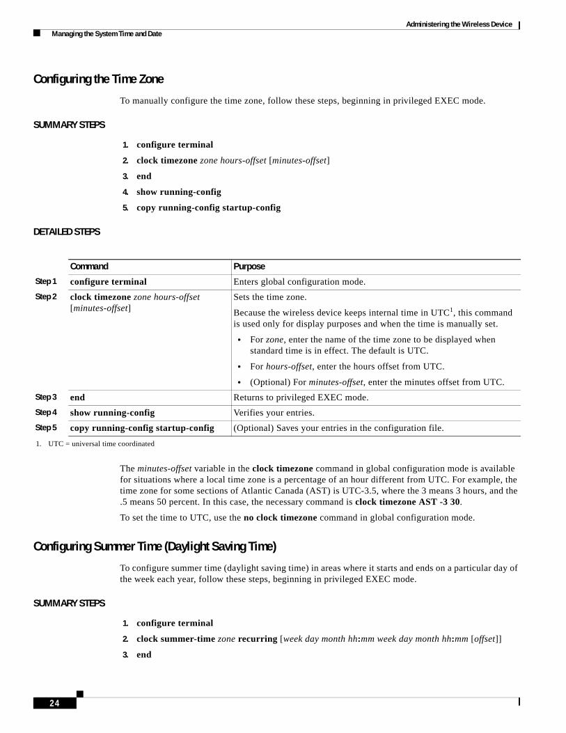
Administering the Wireless Device Managing the System Time and Date
Configuring the Time Zone
To manually configure the time zone, follow these steps, beginning in privileged EXEC mode.
SUMMARY STEPS
1. configure terminal
2. clock timezone zone hours-offset [minutes-offset]
3. end
4. show running-config
5. copy running-config startup-config
DETAILED STEPS
The minutes-offset variable in the clock timezone command in global configuration mode is available for situations where a local time zone is a percentage of an hour different from UTC. For example, the time zone for some sections of Atlantic Canada (AST) is UTC-3.5, where the 3 means 3 hours, and the .5 means 50 percent. In this case, the necessary command is clock timezone AST -3 30.
To set the time to UTC, use the no clock timezone command in global configuration mode.
Configuring Summer Time (Daylight Saving Time)
To configure summer time (daylight saving time) in areas where it starts and ends on a particular day of the week each year, follow these steps, beginning in privileged EXEC mode.
SUMMARY STEPS
1. configure terminal
2. clock summer-time zone recurring [week day month hh:mm week day month hh:mm [offset]]
3. end
Command Purpose
Step 1 configure terminal Enters global configuration mode.
Step 2 clock timezone zone hours-offset [minutes-offset]
Sets the time zone.
Because the wireless device keeps internal time in UTC1, this command is used only for display purposes and when the time is manually set.
• For zone, enter the name of the time zone to be displayed when standard time is in effect. The default is UTC.
• For hours-offset, enter the hours offset from UTC.
• (Optional) For minutes-offset, enter the minutes offset from UTC.
1. UTC = universal time coordinated
Step 3 end Returns to privileged EXEC mode.
Step 4 show running-config Verifies your entries.
Step 5 copy running-config startup-config (Optional) Saves your entries in the configuration file.
24
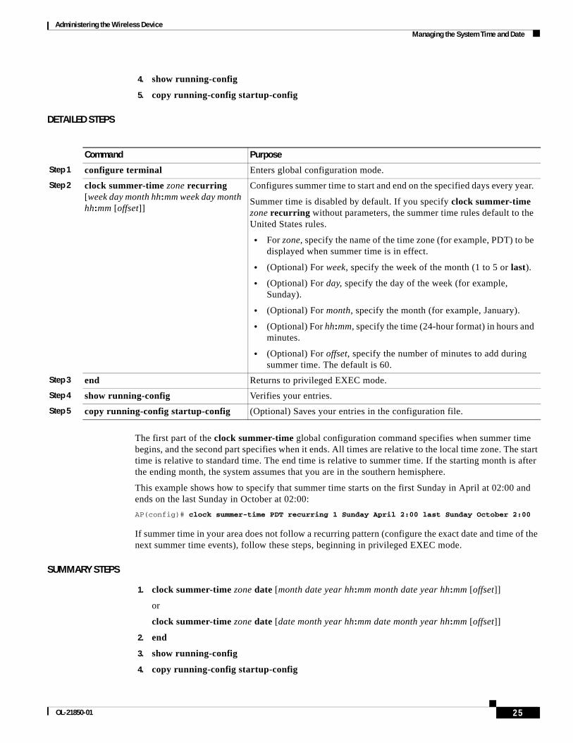
Administering the Wireless Device Managing the System Time and Date
4. show running-config
5. copy running-config startup-config
DETAILED STEPS
The first part of the clock summer-time global configuration command specifies when summer time begins, and the second part specifies when it ends. All times are relative to the local time zone. The start time is relative to standard time. The end time is relative to summer time. If the starting month is after the ending month, the system assumes that you are in the southern hemisphere.
This example shows how to specify that summer time starts on the first Sunday in April at 02:00 and ends on the last Sunday in October at 02:00:
AP(config)# clock summer-time PDT recurring 1 Sunday April 2:00 last Sunday October 2:00
If summer time in your area does not follow a recurring pattern (configure the exact date and time of the next summer time events), follow these steps, beginning in privileged EXEC mode.
SUMMARY STEPS
1. clock summer-time zone date [month date year hh:mm month date year hh:mm [offset]]
or
clock summer-time zone date [date month year hh:mm date month year hh:mm [offset]]
2. end
3. show running-config
4. copy running-config startup-config
Command Purpose
Step 1 configure terminal Enters global configuration mode.
Step 2 clock summer-time zone recurring [week day month hh:mm week day month hh:mm [offset]]
Configures summer time to start and end on the specified days every year.
Summer time is disabled by default. If you specify clock summer-time zone recurring without parameters, the summer time rules default to the United States rules.
• For zone, specify the name of the time zone (for example, PDT) to be displayed when summer time is in effect.
• (Optional) For week, specify the week of the month (1 to 5 or last).
• (Optional) For day, specify the day of the week (for example, Sunday).
• (Optional) For month, specify the month (for example, January).
• (Optional) For hh:mm, specify the time (24-hour format) in hours and minutes.
• (Optional) For offset, specify the number of minutes to add during summer time. The default is 60.
Step 3 end Returns to privileged EXEC mode.
Step 4 show running-config Verifies your entries.
Step 5 copy running-config startup-config (Optional) Saves your entries in the configuration file.
25OL-21850-01
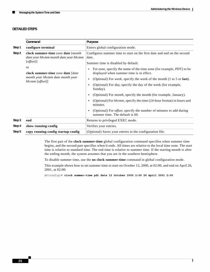
Administering the Wireless Device Managing the System Time and Date
DETAILED STEPS
The first part of the clock summer-time global configuration command specifies when summer time begins, and the second part specifies when it ends. All times are relative to the local time zone. The start time is relative to standard time. The end time is relative to summer time. If the starting month is after the ending month, the system assumes that you are in the southern hemisphere.
To disable summer time, use the no clock summer-time command in global configuration mode.
This example shows how to set summer time to start on October 12, 2000, at 02:00, and end on April 26, 2001, at 02:00:
AP(config)# clock summer-time pdt date 12 October 2000 2:00 26 April 2001 2:00
Command Purpose
Step 1 configure terminal Enters global configuration mode.
Step 2 clock summer-time zone date [month date year hh:mm month date year hh:mm [offset]]
or
clock summer-time zone date [date month year hh:mm date month year hh:mm [offset]]
Configures summer time to start on the first date and end on the second date.
Summer time is disabled by default.
• For zone, specify the name of the time zone (for example, PDT) to be displayed when summer time is in effect.
• (Optional) For week, specify the week of the month (1 to 5 or last).
• (Optional) For day, specify the day of the week (for example, Sunday).
• (Optional) For month, specify the month (for example, January).
• (Optional) For hh:mm, specify the time (24-hour format) in hours and minutes.
• (Optional) For offset, specify the number of minutes to add during summer time. The default is 60.
Step 3 end Returns to privileged EXEC mode.
Step 4 show running-config Verifies your entries.
Step 5 copy running-config startup-config (Optional) Saves your entries in the configuration file.
26

Administering the Wireless Device Configuring a System Name and Prompt
Configuring a System Name and PromptYou configure the system name on the wireless device to identify it. By default, the system name and prompt are ap.
If you have not configured a system prompt, the first 20 characters of the system name are used as the system prompt. A greater-than symbol (>) is appended. The prompt is updated whenever the system name changes, unless you manually configure the prompt by using the prompt command in global configuration mode.
Note For complete syntax and usage information for the commands used in this section, see Cisco IOS Configuration Fundamentals Command Reference and Cisco IOS IP Addressing Services Command Reference.
This section contains the following configuration information:
• Default System Name and Prompt Configuration, page 27
• Configuring a System Name, page 27
• Understanding DNS, page 28
Default System Name and Prompt ConfigurationThe default access point system name and prompt are ap.
Configuring a System NameTo manually configure a system name, follow these steps, beginning in privileged EXEC mode.
SUMMARY STEPS
1. configure terminal
2. hostname name
3. end
4. show running-config
5. copy running-config startup-config
27OL-21850-01

Administering the Wireless Device Configuring a System Name and Prompt
DETAILED STEPS
When you set the system name, the name is also used as the system prompt.
To return to the default hostname, use the no hostname command in global configuration mode.
Understanding DNSThe DNS protocol controls the Domain Name System (DNS), a distributed database with which you can map hostnames to IP addresses. When you configure DNS on the wireless device, you can substitute the hostname for the IP address with all IP commands, such as ping, telnet, connect, and related Telnet support operations.
IP defines a hierarchical naming scheme that allows a device to be identified by its location or domain. Domain names are pieced together with periods (.) as the delimiting characters. For example, Cisco Systems is a commercial organization that IP identifies by a com domain name, so its domain name is cisco.com. A specific device in this domain, such as the File Transfer Protocol (FTP) system, is identified as ftp.cisco.com.
To keep track of domain names, IP has defined the concept of a domain name server, which holds a cache (or database) of names mapped to IP addresses. To map domain names to IP addresses, you must first identify the hostnames, specify the name server that is present on your network, and enable the DNS.
This section contains the following configuration information:
• Default DNS Configuration, page 29
• Setting Up DNS, page 29
• Displaying the DNS Configuration, page 30
Command Purpose
Step 1 configure terminal Enters global configuration mode.
Step 2 hostname name Manually configures a system name.
The default setting is ap.
Note When you change the system name, the wireless device radios reset, and associated client devices disassociate and quickly reassociate.
Note You can enter up to 63 characters for the system name. However, when the wireless device identifies itself to client devices, it uses only the first 15 characters in the system name. If it is important for client users to distinguish between devices, make sure that a unique portion of the system name appears in the first 15 characters.
Step 3 end Returns to privileged EXEC mode.
Step 4 show running-config Verifies your entries.
Step 5 copy running-config startup-config (Optional) Saves your entries in the configuration file.
28
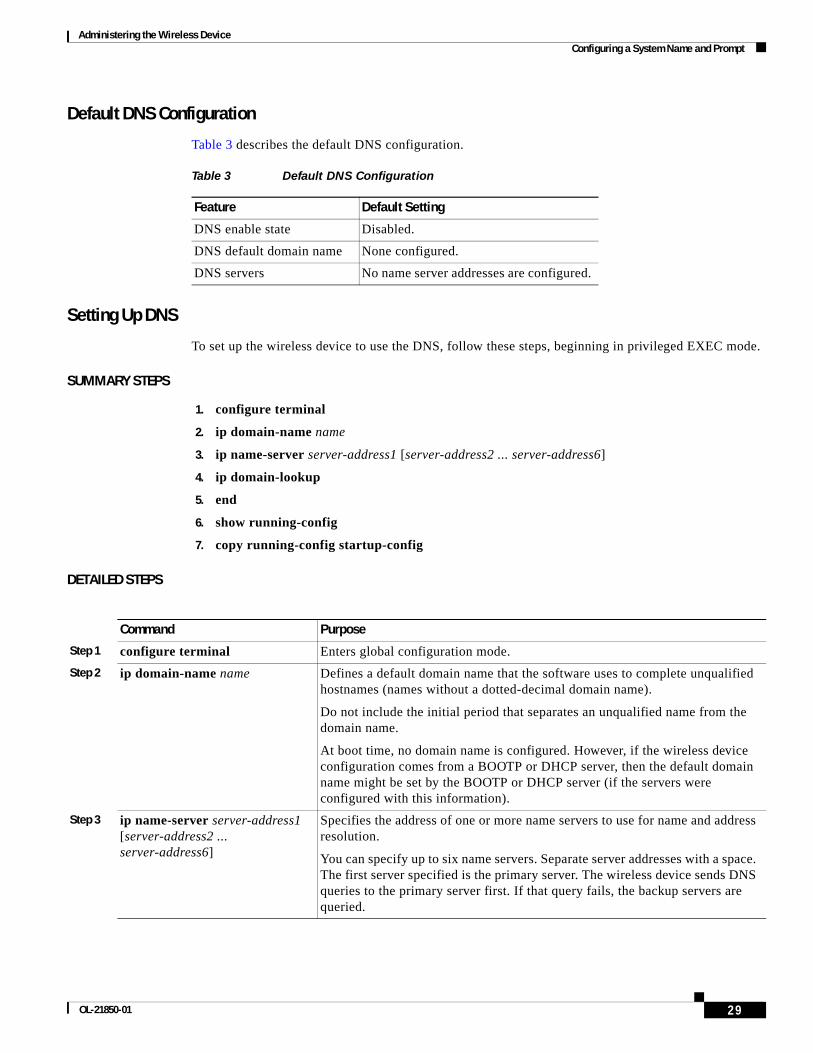
Administering the Wireless Device Configuring a System Name and Prompt
Default DNS Configuration
Table 3 describes the default DNS configuration.
Setting Up DNS
To set up the wireless device to use the DNS, follow these steps, beginning in privileged EXEC mode.
SUMMARY STEPS
1. configure terminal
2. ip domain-name name
3. ip name-server server-address1 [server-address2 ... server-address6]
4. ip domain-lookup
5. end
6. show running-config
7. copy running-config startup-config
DETAILED STEPS
Table 3 Default DNS Configuration
Feature Default Setting
DNS enable state Disabled.
DNS default domain name None configured.
DNS servers No name server addresses are configured.
Command Purpose
Step 1 configure terminal Enters global configuration mode.
Step 2 ip domain-name name Defines a default domain name that the software uses to complete unqualified hostnames (names without a dotted-decimal domain name).
Do not include the initial period that separates an unqualified name from the domain name.
At boot time, no domain name is configured. However, if the wireless device configuration comes from a BOOTP or DHCP server, then the default domain name might be set by the BOOTP or DHCP server (if the servers were configured with this information).
Step 3 ip name-server server-address1 [server-address2 ... server-address6]
Specifies the address of one or more name servers to use for name and address resolution.
You can specify up to six name servers. Separate server addresses with a space. The first server specified is the primary server. The wireless device sends DNS queries to the primary server first. If that query fails, the backup servers are queried.
29OL-21850-01
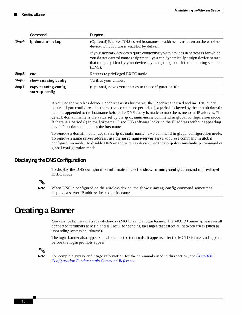
Administering the Wireless Device Creating a Banner
If you use the wireless device IP address as its hostname, the IP address is used and no DNS query occurs. If you configure a hostname that contains no periods (.), a period followed by the default domain name is appended to the hostname before the DNS query is made to map the name to an IP address. The default domain name is the value set by the ip domain-name command in global configuration mode. If there is a period (.) in the hostname, Cisco IOS software looks up the IP address without appending any default domain name to the hostname.
To remove a domain name, use the no ip domain-name name command in global configuration mode. To remove a name server address, use the no ip name-server server-address command in global configuration mode. To disable DNS on the wireless device, use the no ip domain-lookup command in global configuration mode.
Displaying the DNS Configuration
To display the DNS configuration information, use the show running-config command in privileged EXEC mode.
Note When DNS is configured on the wireless device, the show running-config command sometimes displays a server IP address instead of its name.
Creating a BannerYou can configure a message-of-the-day (MOTD) and a login banner. The MOTD banner appears on all connected terminals at login and is useful for sending messages that affect all network users (such as impending system shutdowns).
The login banner also appears on all connected terminals. It appears after the MOTD banner and appears before the login prompts appear.
Note For complete syntax and usage information for the commands used in this section, see Cisco IOS Configuration Fundamentals Command Reference.
Step 4 ip domain-lookup (Optional) Enables DNS-based hostname-to-address translation on the wireless device. This feature is enabled by default.
If your network devices require connectivity with devices in networks for which you do not control name assignment, you can dynamically assign device names that uniquely identify your devices by using the global Internet naming scheme (DNS).
Step 5 end Returns to privileged EXEC mode.
Step 6 show running-config Verifies your entries.
Step 7 copy running-config startup-config
(Optional) Saves your entries in the configuration file.
Command Purpose
30
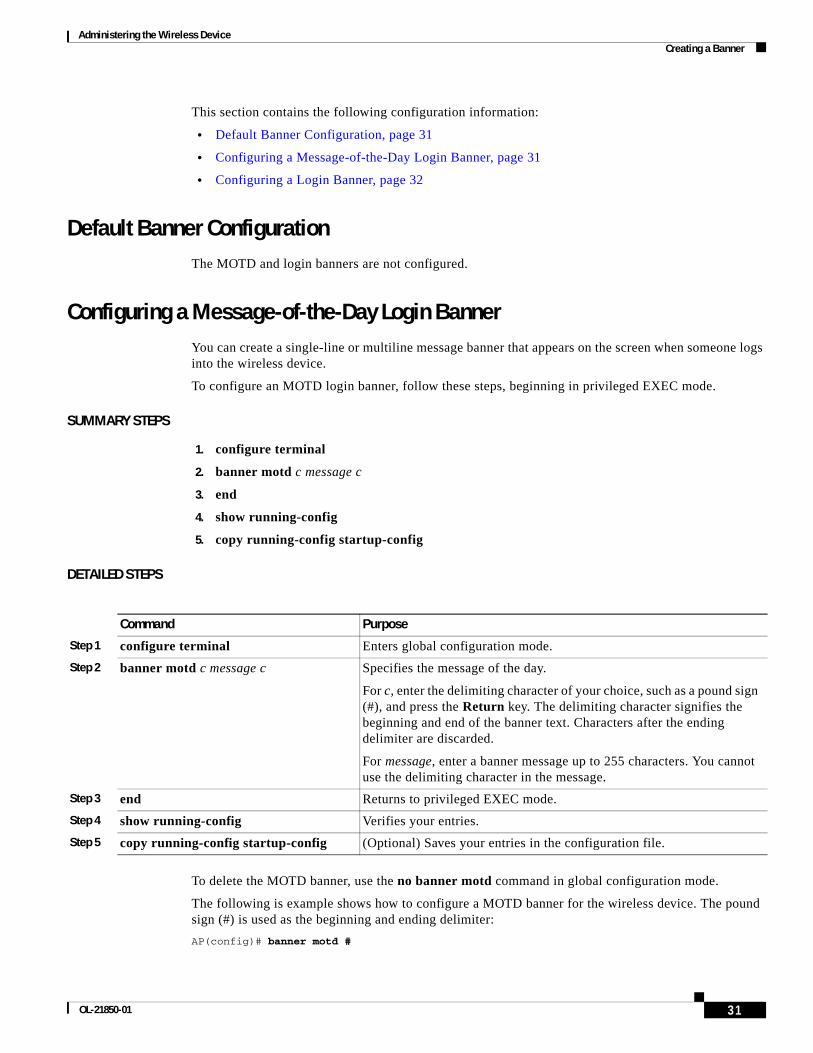
Administering the Wireless Device Creating a Banner
This section contains the following configuration information:
• Default Banner Configuration, page 31
• Configuring a Message-of-the-Day Login Banner, page 31
• Configuring a Login Banner, page 32
Default Banner ConfigurationThe MOTD and login banners are not configured.
Configuring a Message-of-the-Day Login BannerYou can create a single-line or multiline message banner that appears on the screen when someone logs into the wireless device.
To configure an MOTD login banner, follow these steps, beginning in privileged EXEC mode.
SUMMARY STEPS
1. configure terminal
2. banner motd c message c
3. end
4. show running-config
5. copy running-config startup-config
DETAILED STEPS
To delete the MOTD banner, use the no banner motd command in global configuration mode.
The following is example shows how to configure a MOTD banner for the wireless device. The pound sign (#) is used as the beginning and ending delimiter:
AP(config)# banner motd #
Command Purpose
Step 1 configure terminal Enters global configuration mode.
Step 2 banner motd c message c Specifies the message of the day.
For c, enter the delimiting character of your choice, such as a pound sign (#), and press the Return key. The delimiting character signifies the beginning and end of the banner text. Characters after the ending delimiter are discarded.
For message, enter a banner message up to 255 characters. You cannot use the delimiting character in the message.
Step 3 end Returns to privileged EXEC mode.
Step 4 show running-config Verifies your entries.
Step 5 copy running-config startup-config (Optional) Saves your entries in the configuration file.
31OL-21850-01
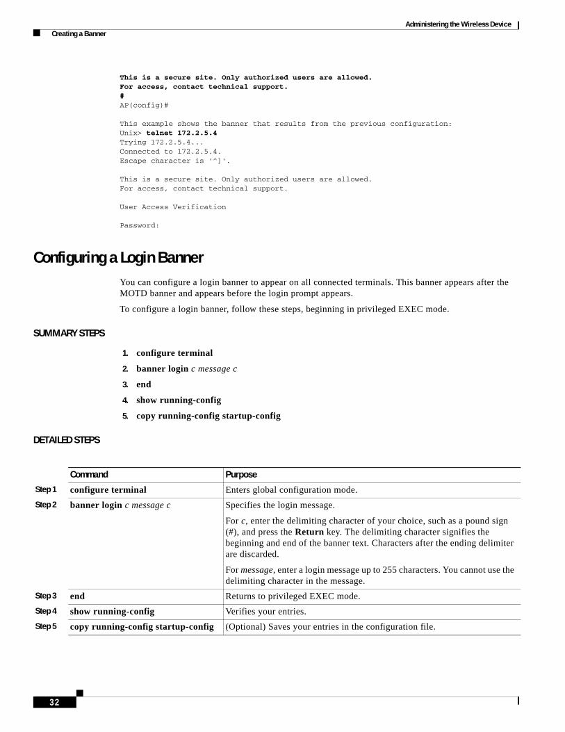
Administering the Wireless Device Creating a Banner
This is a secure site. Only authorized users are allowed.For access, contact technical support.#AP(config)#
This example shows the banner that results from the previous configuration:Unix> telnet 172.2.5.4Trying 172.2.5.4...Connected to 172.2.5.4.Escape character is '^]'.
This is a secure site. Only authorized users are allowed.For access, contact technical support.
User Access Verification
Password:
Configuring a Login BannerYou can configure a login banner to appear on all connected terminals. This banner appears after the MOTD banner and appears before the login prompt appears.
To configure a login banner, follow these steps, beginning in privileged EXEC mode.
SUMMARY STEPS
1. configure terminal
2. banner login c message c
3. end
4. show running-config
5. copy running-config startup-config
DETAILED STEPS
Command Purpose
Step 1 configure terminal Enters global configuration mode.
Step 2 banner login c message c Specifies the login message.
For c, enter the delimiting character of your choice, such as a pound sign (#), and press the Return key. The delimiting character signifies the beginning and end of the banner text. Characters after the ending delimiter are discarded.
For message, enter a login message up to 255 characters. You cannot use the delimiting character in the message.
Step 3 end Returns to privileged EXEC mode.
Step 4 show running-config Verifies your entries.
Step 5 copy running-config startup-config (Optional) Saves your entries in the configuration file.
32

Administering the Wireless Device Configuring Ethernet Speed and Duplex Settings
To delete the login banner, use the no banner login command in global configuration mode.
The following example shows how to configure a login banner for the wireless device using the dollar sign ($) as the beginning and ending delimiter:
AP(config)# banner login $Access for authorized users only. Please enter your username and password.$AP(config)#
Configuring Ethernet Speed and Duplex SettingsThe Cisco 1941-W ISR interface supports only 1000 Mbps speed and duplex settings by default, and the interface is always up. When the wireless device receives inline power from a switch, any change in the speed or duplex settings that resets the Ethernet link reboots the wireless device.
Note The speed and duplex settings on the wireless device Ethernet port must match the Ethernet settings on the port to which the wireless device is connected. If you change the settings on the port to which the wireless device is connected, change the settings on the wireless device Ethernet port to match.
The Ethernet speed and duplex are set to auto by default. To configure Ethernet speed and duplex, follow these steps, beginning in privileged EXEC mode.
SUMMARY STEPS
1. configure terminal
2. interface fastethernet0
3. speed {10 | 100 | auto}
4. duplex {auto | full | half}
5. end
6. show running-config
7. copy running-config startup-config
DETAILED STEPS
Command Purpose
Step 1 configure terminal Enters global configuration mode.
Step 2 interface fastethernet0 Enters configuration interface mode.
Step 3 speed {10 | 100 | auto} Configures the Ethernet speed. we recommend that you use auto, the default setting.
Step 4 duplex {auto | full | half} Configures the duplex setting. we recommend that you use auto, the default setting.
Step 5 end Returns to privileged EXEC mode.
33OL-21850-01
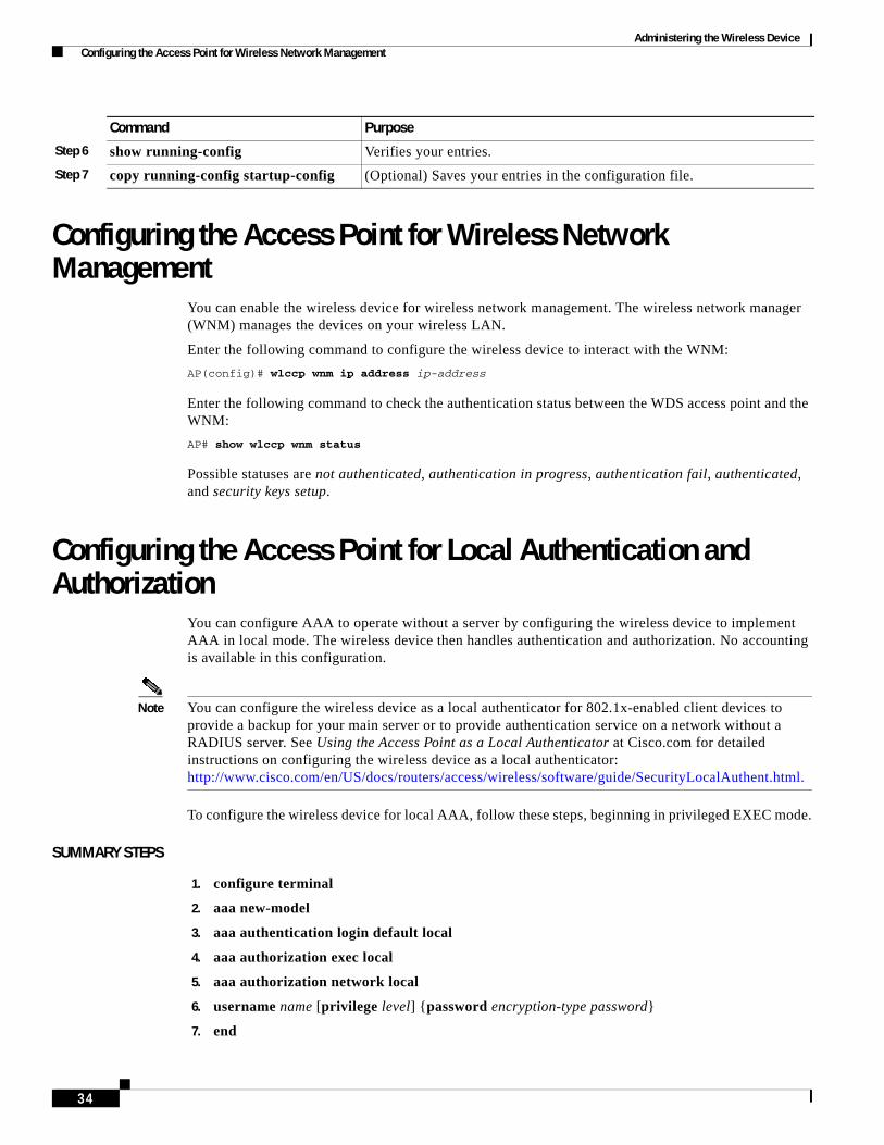
Administering the Wireless Device Configuring the Access Point for Wireless Network Management
Configuring the Access Point for Wireless Network Management
You can enable the wireless device for wireless network management. The wireless network manager (WNM) manages the devices on your wireless LAN.
Enter the following command to configure the wireless device to interact with the WNM:
AP(config)# wlccp wnm ip address ip-address
Enter the following command to check the authentication status between the WDS access point and the WNM:
AP# show wlccp wnm status
Possible statuses are not authenticated, authentication in progress, authentication fail, authenticated, and security keys setup.
Configuring the Access Point for Local Authentication and Authorization
You can configure AAA to operate without a server by configuring the wireless device to implement AAA in local mode. The wireless device then handles authentication and authorization. No accounting is available in this configuration.
Note You can configure the wireless device as a local authenticator for 802.1x-enabled client devices to provide a backup for your main server or to provide authentication service on a network without a RADIUS server. See Using the Access Point as a Local Authenticator at Cisco.com for detailed instructions on configuring the wireless device as a local authenticator: http://www.cisco.com/en/US/docs/routers/access/wireless/software/guide/SecurityLocalAuthent.html.
To configure the wireless device for local AAA, follow these steps, beginning in privileged EXEC mode.
SUMMARY STEPS
1. configure terminal
2. aaa new-model
3. aaa authentication login default local
4. aaa authorization exec local
5. aaa authorization network local
6. username name [privilege level] {password encryption-type password}
7. end
Step 6 show running-config Verifies your entries.
Step 7 copy running-config startup-config (Optional) Saves your entries in the configuration file.
Command Purpose
34
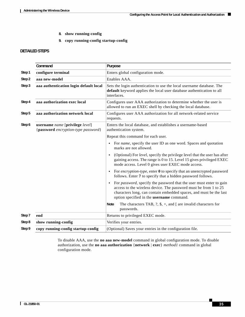
Administering the Wireless Device Configuring the Access Point for Local Authentication and Authorization
8. show running-config
9. copy running-config startup-config
DETAILED STEPS
To disable AAA, use the no aaa new-model command in global configuration mode. To disable authorization, use the no aaa authorization {network | exec} method1 command in global configuration mode.
Command Purpose
Step 1 configure terminal Enters global configuration mode.
Step 2 aaa new-model Enables AAA.
Step 3 aaa authentication login default local Sets the login authentication to use the local username database. The default keyword applies the local user database authentication to all interfaces.
Step 4 aaa authorization exec local Configures user AAA authorization to determine whether the user is allowed to run an EXEC shell by checking the local database.
Step 5 aaa authorization network local Configures user AAA authorization for all network-related service requests.
Step 6 username name [privilege level] {password encryption-type password}
Enters the local database, and establishes a username-based authentication system.
Repeat this command for each user.
• For name, specify the user ID as one word. Spaces and quotation marks are not allowed.
• (Optional) For level, specify the privilege level that the user has after gaining access. The range is 0 to 15. Level 15 gives privileged EXEC mode access. Level 0 gives user EXEC mode access.
• For encryption-type, enter 0 to specify that an unencrypted password follows. Enter 7 to specify that a hidden password follows.
• For password, specify the password that the user must enter to gain access to the wireless device. The password must be from 1 to 25 characters long, can contain embedded spaces, and must be the last option specified in the username command.
Note The characters TAB, ?, $, +, and [ are invalid characters for passwords.
Step 7 end Returns to privileged EXEC mode.
Step 8 show running-config Verifies your entries.
Step 9 copy running-config startup-config (Optional) Saves your entries in the configuration file.
35OL-21850-01
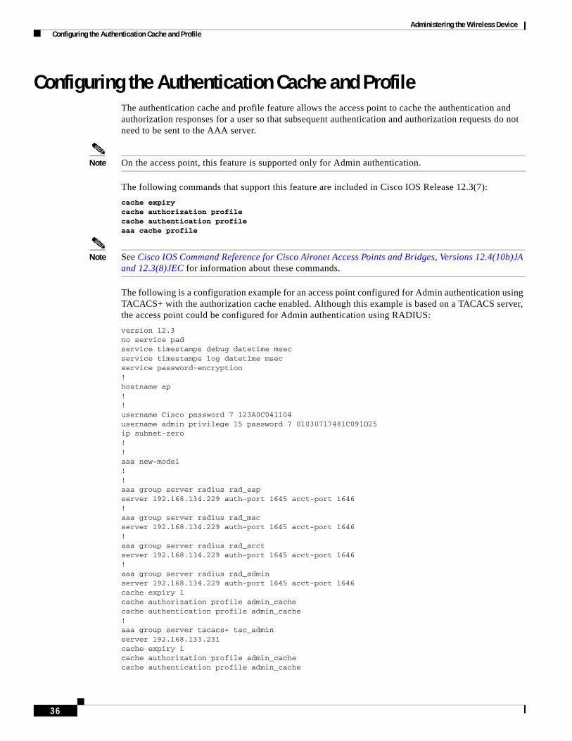
Administering the Wireless Device Configuring the Authentication Cache and Profile
Configuring the Authentication Cache and ProfileThe authentication cache and profile feature allows the access point to cache the authentication and authorization responses for a user so that subsequent authentication and authorization requests do not need to be sent to the AAA server.
Note On the access point, this feature is supported only for Admin authentication.
The following commands that support this feature are included in Cisco IOS Release 12.3(7):
cache expirycache authorization profilecache authentication profileaaa cache profile
Note See Cisco IOS Command Reference for Cisco Aironet Access Points and Bridges, Versions 12.4(10b)JA and 12.3(8)JEC for information about these commands.
The following is a configuration example for an access point configured for Admin authentication using TACACS+ with the authorization cache enabled. Although this example is based on a TACACS server, the access point could be configured for Admin authentication using RADIUS:
version 12.3 no service pad service timestamps debug datetime msec service timestamps log datetime msec service password-encryption ! hostname ap ! ! username Cisco password 7 123A0C041104 username admin privilege 15 password 7 01030717481C091D25 ip subnet-zero ! ! aaa new-model ! ! aaa group server radius rad_eap server 192.168.134.229 auth-port 1645 acct-port 1646 ! aaa group server radius rad_mac server 192.168.134.229 auth-port 1645 acct-port 1646 ! aaa group server radius rad_acct server 192.168.134.229 auth-port 1645 acct-port 1646 ! aaa group server radius rad_admin server 192.168.134.229 auth-port 1645 acct-port 1646 cache expiry 1 cache authorization profile admin_cache cache authentication profile admin_cache ! aaa group server tacacs+ tac_admin server 192.168.133.231 cache expiry 1 cache authorization profile admin_cache cache authentication profile admin_cache
36

Administering the Wireless Device Configuring the Authentication Cache and Profile
! aaa group server radius rad_pmip ! aaa group server radius dummy ! aaa authentication login default local cache tac_admin group tac_admin aaa authentication login eap_methods group rad_eap aaa authentication login mac_methods local aaa authorization exec default local cache tac_admin group tac_admin aaa accounting network acct_methods start-stop group rad_acct aaa cache profile admin_cache all ! aaa session-id common ! ! ! bridge irb ! ! interface Dot11Radio0 no ip address no ip route-cache shutdown speed basic-1.0 basic-2.0 basic-5.5 6.0 9.0 basic-11.0 12.0 18.0 24.0 36.0 48.0 54.0 station-role root bridge-group 1 bridge-group 1 subscriber-loop-control bridge-group 1 block-unknown-source no bridge-group 1 source-learning no bridge-group 1 unicast-flooding bridge-group 1 spanning-disabled ! interface Dot11Radio1 no ip address no ip route-cache shutdown speed basic-6.0 9.0 basic-12.0 18.0 basic-24.0 36.0 48.0 54.0 station-role root bridge-group 1 bridge-group 1 subscriber-loop-control bridge-group 1 block-unknown-source no bridge-group 1 source-learning no bridge-group 1 unicast-flooding bridge-group 1 spanning-disabled ! interface FastEthernet0 no ip address no ip route-cache duplex auto speed auto bridge-group 1 no bridge-group 1 source-learning bridge-group 1 spanning-disabled ! interface BVI1 ip address 192.168.133.207 255.255.255.0 no ip route-cache ! ip http server ip http authentication aaa no ip http secure-server ip http help-path http://www.cisco.com/warp/public/779/smbiz/prodconfig/help/eag ip radius source-interface BVI1
37OL-21850-01
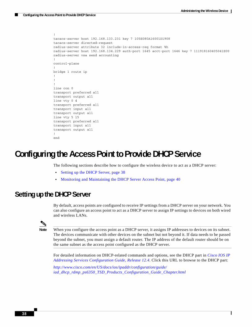
Administering the Wireless Device Configuring the Access Point to Provide DHCP Service
! tacacs-server host 192.168.133.231 key 7 105E080A16001D1908 tacacs-server directed-request radius-server attribute 32 include-in-access-req format %h radius-server host 192.168.134.229 auth-port 1645 acct-port 1646 key 7 111918160405041E00 radius-server vsa send accounting ! control-plane ! bridge 1 route ip ! ! ! line con 0 transport preferred all transport output all line vty 0 4 transport preferred all transport input all transport output all line vty 5 15 transport preferred all transport input all transport output all ! end
Configuring the Access Point to Provide DHCP ServiceThe following sections describe how to configure the wireless device to act as a DHCP server:
• Setting up the DHCP Server, page 38
• Monitoring and Maintaining the DHCP Server Access Point, page 40
Setting up the DHCP ServerBy default, access points are configured to receive IP settings from a DHCP server on your network. You can also configure an access point to act as a DHCP server to assign IP settings to devices on both wired and wireless LANs.
Note When you configure the access point as a DHCP server, it assigns IP addresses to devices on its subnet. The devices communicate with other devices on the subnet but not beyond it. If data needs to be passed beyond the subnet, you must assign a default router. The IP address of the default router should be on the same subnet as the access point configured as the DHCP server.
For detailed information on DHCP-related commands and options, see the DHCP part in Cisco IOS IP Addressing Services Configuration Guide, Release 12.4. Click this URL to browse to the DHCP part:
http://www.cisco.com/en/US/docs/ios/ipaddr/configuration/guide/ iad_dhcp_rdmp_ps6350_TSD_Products_Configuration_Guide_Chapter.html
38
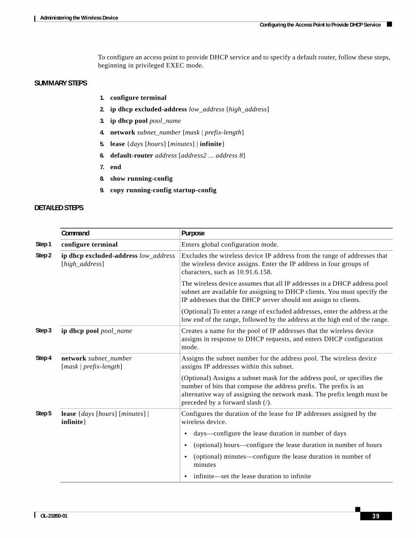
Administering the Wireless Device Configuring the Access Point to Provide DHCP Service
To configure an access point to provide DHCP service and to specify a default router, follow these steps, beginning in privileged EXEC mode.
SUMMARY STEPS
1. configure terminal
2. ip dhcp excluded-address low_address [high_address]
3. ip dhcp pool pool_name
4. network subnet_number [mask | prefix-length]
5. lease {days [hours] [minutes] | infinite}
6. default-router address [address2 ... address 8]
7. end
8. show running-config
9. copy running-config startup-config
DETAILED STEPS
Command Purpose
Step 1 configure terminal Enters global configuration mode.
Step 2 ip dhcp excluded-address low_address [high_address]
Excludes the wireless device IP address from the range of addresses that the wireless device assigns. Enter the IP address in four groups of characters, such as 10.91.6.158.
The wireless device assumes that all IP addresses in a DHCP address pool subnet are available for assigning to DHCP clients. You must specify the IP addresses that the DHCP server should not assign to clients.
(Optional) To enter a range of excluded addresses, enter the address at the low end of the range, followed by the address at the high end of the range.
Step 3 ip dhcp pool pool_name Creates a name for the pool of IP addresses that the wireless device assigns in response to DHCP requests, and enters DHCP configuration mode.
Step 4 network subnet_number [mask | prefix-length]
Assigns the subnet number for the address pool. The wireless device assigns IP addresses within this subnet.
(Optional) Assigns a subnet mask for the address pool, or specifies the number of bits that compose the address prefix. The prefix is an alternative way of assigning the network mask. The prefix length must be preceded by a forward slash (/).
Step 5 lease {days [hours] [minutes] | infinite}
Configures the duration of the lease for IP addresses assigned by the wireless device.
• days—configure the lease duration in number of days
• (optional) hours—configure the lease duration in number of hours
• (optional) minutes—configure the lease duration in number of minutes
• infinite—set the lease duration to infinite
39OL-21850-01
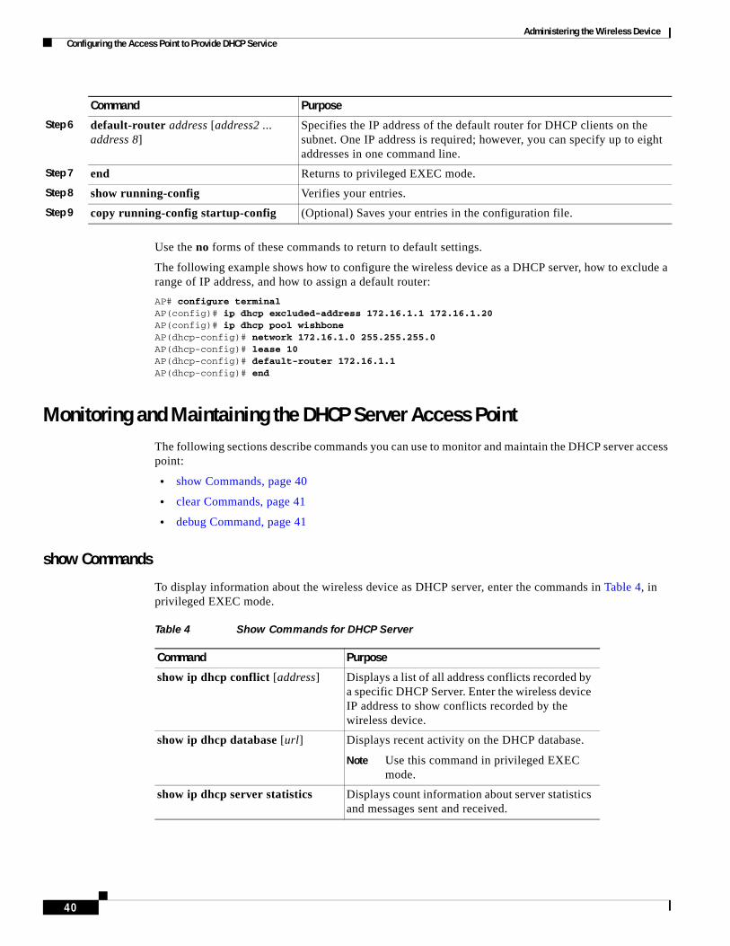
Administering the Wireless Device Configuring the Access Point to Provide DHCP Service
Use the no forms of these commands to return to default settings.
The following example shows how to configure the wireless device as a DHCP server, how to exclude a range of IP address, and how to assign a default router:
AP# configure terminalAP(config)# ip dhcp excluded-address 172.16.1.1 172.16.1.20AP(config)# ip dhcp pool wishboneAP(dhcp-config)# network 172.16.1.0 255.255.255.0AP(dhcp-config)# lease 10AP(dhcp-config)# default-router 172.16.1.1AP(dhcp-config)# end
Monitoring and Maintaining the DHCP Server Access PointThe following sections describe commands you can use to monitor and maintain the DHCP server access point:
• show Commands, page 40
• clear Commands, page 41
• debug Command, page 41
show Commands
To display information about the wireless device as DHCP server, enter the commands in Table 4, in privileged EXEC mode.
Step 6 default-router address [address2 ... address 8]
Specifies the IP address of the default router for DHCP clients on the subnet. One IP address is required; however, you can specify up to eight addresses in one command line.
Step 7 end Returns to privileged EXEC mode.
Step 8 show running-config Verifies your entries.
Step 9 copy running-config startup-config (Optional) Saves your entries in the configuration file.
Command Purpose
Table 4 Show Commands for DHCP Server
Command Purpose
show ip dhcp conflict [address] Displays a list of all address conflicts recorded by a specific DHCP Server. Enter the wireless device IP address to show conflicts recorded by the wireless device.
show ip dhcp database [url] Displays recent activity on the DHCP database.
Note Use this command in privileged EXEC mode.
show ip dhcp server statistics Displays count information about server statistics and messages sent and received.
40
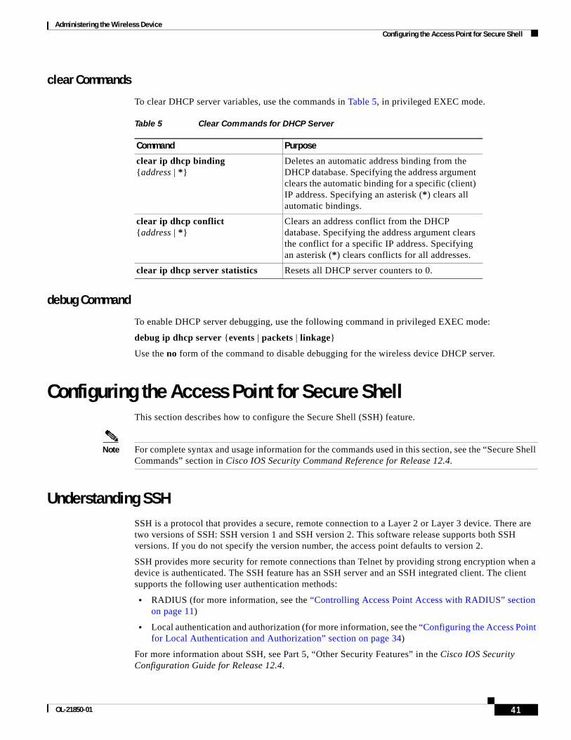
Administering the Wireless Device Configuring the Access Point for Secure Shell
clear Commands
To clear DHCP server variables, use the commands in Table 5, in privileged EXEC mode.
debug Command
To enable DHCP server debugging, use the following command in privileged EXEC mode:
debug ip dhcp server {events | packets | linkage}
Use the no form of the command to disable debugging for the wireless device DHCP server.
Configuring the Access Point for Secure ShellThis section describes how to configure the Secure Shell (SSH) feature.
Note For complete syntax and usage information for the commands used in this section, see the “Secure Shell Commands” section in Cisco IOS Security Command Reference for Release 12.4.
Understanding SSH SSH is a protocol that provides a secure, remote connection to a Layer 2 or Layer 3 device. There are two versions of SSH: SSH version 1 and SSH version 2. This software release supports both SSH versions. If you do not specify the version number, the access point defaults to version 2.
SSH provides more security for remote connections than Telnet by providing strong encryption when a device is authenticated. The SSH feature has an SSH server and an SSH integrated client. The client supports the following user authentication methods:
• RADIUS (for more information, see the “Controlling Access Point Access with RADIUS” section on page 11)
• Local authentication and authorization (for more information, see the “Configuring the Access Point for Local Authentication and Authorization” section on page 34)
For more information about SSH, see Part 5, “Other Security Features” in the Cisco IOS Security Configuration Guide for Release 12.4.
Table 5 Clear Commands for DHCP Server
Command Purpose
clear ip dhcp binding {address | *}
Deletes an automatic address binding from the DHCP database. Specifying the address argument clears the automatic binding for a specific (client) IP address. Specifying an asterisk (*) clears all automatic bindings.
clear ip dhcp conflict {address | *}
Clears an address conflict from the DHCP database. Specifying the address argument clears the conflict for a specific IP address. Specifying an asterisk (*) clears conflicts for all addresses.
clear ip dhcp server statistics Resets all DHCP server counters to 0.
41OL-21850-01

Administering the Wireless Device Configuring Client ARP Caching
Note The SSH feature in this software release does not support IP Security (IPsec).
Configuring SSHBefore configuring SSH, download the cryptographic software image from Cisco.com. For more information, see the release notes for this release.
For information about configuring SSH and displaying SSH settings, see Part 6, “Other Security Features” in the Cisco IOS Security Configuration Guide for Release 12.4, which is available at Cisco.com at the following link:
http://www.cisco.com/en/US/docs/ios/security/configuration/guide/12_4/sec_12_4_book.html
Configuring Client ARP CachingYou can configure the wireless device to maintain an address resolution protocol (ARP) cache for associated client devices. Maintaining an ARP cache on the wireless device reduces the traffic load on your wireless LAN. ARP caching is disabled by default.
This section contains this information:
• Understanding Client ARP Caching, page 42
• Configuring ARP Caching, page 43
Understanding Client ARP CachingARP caching on the wireless device reduces the traffic on your wireless LAN by stopping ARP requests for client devices at the wireless device. Instead of forwarding ARP requests to client devices, the wireless device responds to requests on behalf of associated client devices.
When ARP caching is disabled, the wireless device forwards all ARP requests through the radio port to associated clients. The client that receives the ARP request responds. When ARP caching is enabled, the wireless device responds to ARP requests for associated clients and does not forward requests to clients. When the wireless device receives an ARP request for an IP address not in the cache, the wireless device drops the request and does not forward it. In its beacon, the wireless device includes an information element to alert client devices that they can safely ignore broadcast messages to increase battery life.
Optional ARP Caching
When a non-Cisco client device is associated to an access point and is not passing data, the wireless device might not know the client IP address. If this situation occurs frequently on your wireless LAN, you can enable optional ARP caching. When ARP caching is optional, the wireless device responds on behalf of clients with IP addresses known to the wireless device but forwards out of its radio port any ARP requests addressed to unknown clients. When the wireless device learns the IP addresses for all associated clients, it drops ARP requests not directed to its associated clients.
42

Administering the Wireless Device Configuring Multiple VLAN and Rate Limiting for Point-to-Multipoint Bridging
Configuring ARP CachingTo configure the wireless device to maintain an ARP cache for associated clients, follow these steps, beginning in privileged EXEC mode.
SUMMARY STEPS
1. configure terminal
2. dot11 arp-cache [optional]
3. end
4. show running-config
5. copy running-config startup-config
DETAILED STEPS
The following example shows how to configure ARP caching on an access point:
AP# configure terminalAP(config)# dot11 arp-cacheAP(config)# end
Configuring Multiple VLAN and Rate Limiting for Point-to-Multipoint Bridging
This feature modifies the way that point-to-multipoint bridging can be configured to operate on multiple VLANs with the ability to control traffic rates on each VLAN.
Note A rate-limiting policy can be applied only to Fast Ethernet ingress ports on non-root bridges.
In a typical scenario, multiple-VLAN support permits users to set up point-to-multipoint bridge links with remote sites, with each remote site on a separate VLAN. This configuration provides the capability for separating and controlling traffic to each site. Rate limiting ensures that no remote site consumes more than a specified amount of the entire link bandwidth. Only uplink traffic can be controlled by using the Fast Ethernet ingress ports of non-root bridges.
Command Purpose
Step 1 configure terminal Enters global configuration mode.
Step 2 dot11 arp-cache [optional] Enables ARP caching on the wireless device.
• (Optional) Use the optional keyword to enable ARP caching only for the client devices whose IP addresses are known to the wireless device.
Step 3 end Returns to privileged EXEC mode.
Step 4 show running-config Verifies your entries.
Step 5 copy running-config startup-config (Optional) Saves your entries in the configuration file.
43OL-21850-01

Administering the Wireless Device Configuring Multiple VLAN and Rate Limiting for Point-to-Multipoint Bridging
Using the class-based policing feature, you can specify the rate limit and apply it to the ingress of the Ethernet interface of a non-root bridge. Applying the rate at the ingress of the Ethernet interface ensures that all incoming Ethernet packets conform to the configured rate.
44

Administering the Wireless Device Configuring Multiple VLAN and Rate Limiting for Point-to-Multipoint Bridging
CCDE, CCENT, CCSI, Cisco Eos, Cisco HealthPresence, Cisco IronPort, the Cisco logo, Cisco Nurse Connect, Cisco Pulse, Cisco SensorBase, Cisco StackPower, Cisco StadiumVision, Cisco TelePresence, Cisco Unified Computing System, Cisco WebEx, DCE, Flip Channels, Flip for Good, Flip Mino, Flipshare (Design), Flip Ultra, Flip Video, Flip Video (Design), Instant Broadband, and Welcome to the Human Network are trademarks; Changing the Way We Work, Live, Play, and Learn, Cisco Capital, Cisco Capital (Design), Cisco:Financed (Stylized), Cisco Store, Flip Gift Card, and One Million Acts of Green are service marks; and Access Registrar, Aironet, AllTouch, AsyncOS, Bringing the Meeting To You, Catalyst, CCDA, CCDP, CCIE, CCIP, CCNA, CCNP, CCSP, CCVP, Cisco, the Cisco Certified Internetwork Expert logo, Cisco IOS, Cisco Lumin, Cisco Nexus, Cisco Press, Cisco Systems, Cisco Systems Capital, the Cisco Systems logo, Cisco Unity, Collaboration Without Limitation, Continuum, EtherFast, EtherSwitch, Event Center, Explorer, Follow Me Browsing, GainMaker, iLYNX, IOS, iPhone, IronPort, the IronPort logo, Laser Link, LightStream, Linksys, MeetingPlace, MeetingPlace Chime Sound, MGX, Networkers, Networking Academy, PCNow, PIX, PowerKEY, PowerPanels, PowerTV, PowerTV (Design), PowerVu, Prisma, ProConnect, ROSA, SenderBase, SMARTnet, Spectrum Expert, StackWise, WebEx, and the WebEx logo are registered trademarks of Cisco Systems, Inc. and/or its affiliates in the United States and certain other countries.
All other trademarks mentioned in this document or website are the property of their respective owners. The use of the word partner does not imply a partnership relationship between Cisco and any other company. (0910R)
Any Internet Protocol (IP) addresses used in this document are not intended to be actual addresses. Any examples, command display output, and figures included in the document are shown for illustrative purposes only. Any use of actual IP addresses in illustrative content is unintentional and coincidental. © 2009-2010 Cisco Systems, Inc. All rights reserved.
45OL-21850-01

Administering the Wireless Device Configuring Multiple VLAN and Rate Limiting for Point-to-Multipoint Bridging
46

P A R T 3
Appendix


Cisco 3900 Series, 2900 Series, and 1900 OL-21850-01
A
P P E N D I X A Cisco IOS CLI for Initial ConfigurationThe following sections describe how to perform the initial configuration using the Cisco Internet Operating System (IOS) command line interface (CLI).
• Prerequisites for Initial Software Configuration Using the Cisco IOS CLI, page A-1
• Using the Cisco IOS CLI to Perform Initial Configuration, page A-2
Note We recommend using Cisco Configuration Professional Express web-based application to configure the initial router settings. See Cisco Configuration Professional Express User Guide at Cisco.com for detailed instructions, http://www.cisco.com/en/US/docs/net_mgmt/cisco_configuration_professional_express/version1_1/ online_help/CCPE11.pdf.
Initial Configuration of the Wireless Access Point on Cisco 1941W Router
The embedded wireless access point (AP) runs its own version of Cisco Internet Operating System (IOS) software. Use Cisco Configuration Professional Express to perform the initial configuration of the access point software. For information on how to configure additional wireless parameters see the “Configuring the Wireless Device” module in this guide.
Prerequisites for Initial Software Configuration Using the Cisco IOS CLI
Follow the instructions in the hardware installation guide for your router to install the chassis, connect cables, and supply power to the hardware.
Timesaver Before supplying power to the router, disconnect all WAN cables from the router to keep it from trying to run the AutoInstall process. The router may try to run AutoInstall if you power it up while there is a WAN connection on both ends and the router does not have a valid configuration file stored in NVRAM (for instance, when you add a new interface). It can take several minutes for the router to determine that AutoInstall is not connected to a remote TCP/IP host.
A-1Series Integrated Services Routers Software
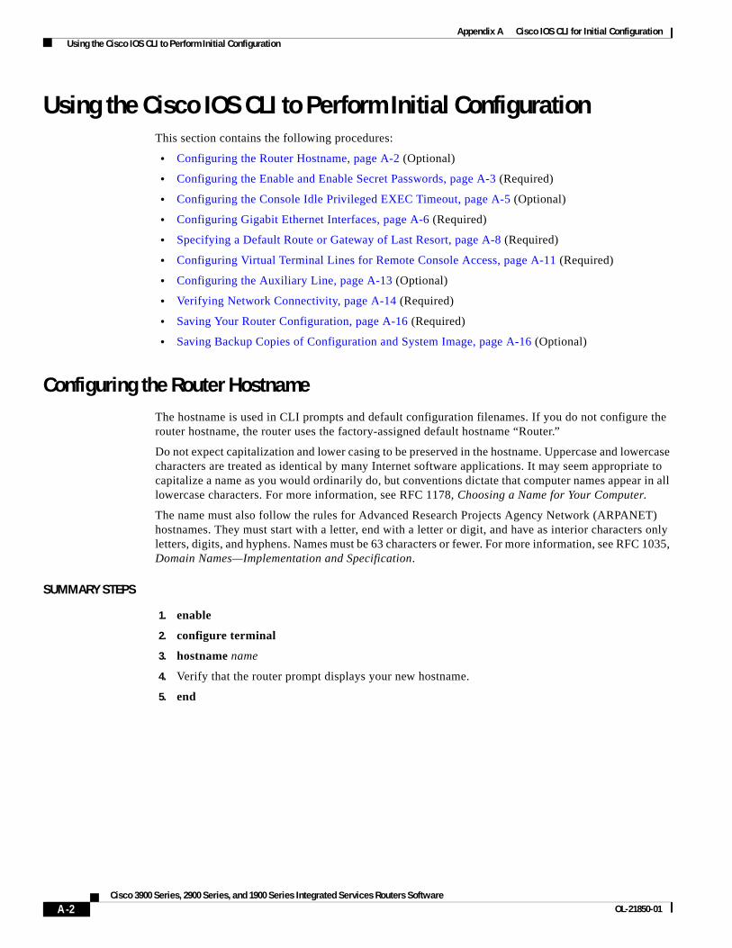
Appendix A Cisco IOS CLI for Initial Configuration Using the Cisco IOS CLI to Perform Initial Configuration
Using the Cisco IOS CLI to Perform Initial ConfigurationThis section contains the following procedures:
• Configuring the Router Hostname, page A-2 (Optional)
• Configuring the Enable and Enable Secret Passwords, page A-3 (Required)
• Configuring the Console Idle Privileged EXEC Timeout, page A-5 (Optional)
• Configuring Gigabit Ethernet Interfaces, page A-6 (Required)
• Specifying a Default Route or Gateway of Last Resort, page A-8 (Required)
• Configuring Virtual Terminal Lines for Remote Console Access, page A-11 (Required)
• Configuring the Auxiliary Line, page A-13 (Optional)
• Verifying Network Connectivity, page A-14 (Required)
• Saving Your Router Configuration, page A-16 (Required)
• Saving Backup Copies of Configuration and System Image, page A-16 (Optional)
Configuring the Router HostnameThe hostname is used in CLI prompts and default configuration filenames. If you do not configure the router hostname, the router uses the factory-assigned default hostname “Router.”
Do not expect capitalization and lower casing to be preserved in the hostname. Uppercase and lowercase characters are treated as identical by many Internet software applications. It may seem appropriate to capitalize a name as you would ordinarily do, but conventions dictate that computer names appear in all lowercase characters. For more information, see RFC 1178, Choosing a Name for Your Computer.
The name must also follow the rules for Advanced Research Projects Agency Network (ARPANET) hostnames. They must start with a letter, end with a letter or digit, and have as interior characters only letters, digits, and hyphens. Names must be 63 characters or fewer. For more information, see RFC 1035, Domain Names—Implementation and Specification.
SUMMARY STEPS
1. enable
2. configure terminal
3. hostname name
4. Verify that the router prompt displays your new hostname.
5. end
A-2Cisco 3900 Series, 2900 Series, and 1900 Series Integrated Services Routers Software
OL-21850-01
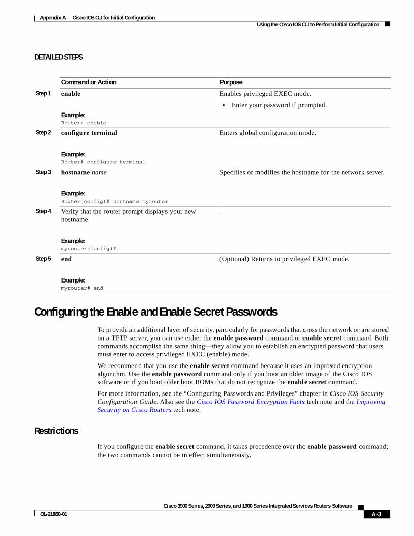
Appendix A Cisco IOS CLI for Initial Configuration Using the Cisco IOS CLI to Perform Initial Configuration
DETAILED STEPS
Configuring the Enable and Enable Secret PasswordsTo provide an additional layer of security, particularly for passwords that cross the network or are stored on a TFTP server, you can use either the enable password command or enable secret command. Both commands accomplish the same thing—they allow you to establish an encrypted password that users must enter to access privileged EXEC (enable) mode.
We recommend that you use the enable secret command because it uses an improved encryption algorithm. Use the enable password command only if you boot an older image of the Cisco IOS software or if you boot older boot ROMs that do not recognize the enable secret command.
For more information, see the “Configuring Passwords and Privileges” chapter in Cisco IOS Security Configuration Guide. Also see the Cisco IOS Password Encryption Facts tech note and the Improving Security on Cisco Routers tech note.
Restrictions
If you configure the enable secret command, it takes precedence over the enable password command; the two commands cannot be in effect simultaneously.
Command or Action Purpose
Step 1 enable
Example:Router> enable
Enables privileged EXEC mode.
• Enter your password if prompted.
Step 2 configure terminal
Example:Router# configure terminal
Enters global configuration mode.
Step 3 hostname name
Example:Router(config)# hostname myrouter
Specifies or modifies the hostname for the network server.
Step 4 Verify that the router prompt displays your new hostname.
Example:myrouter(config)#
—
Step 5 end
Example:myrouter# end
(Optional) Returns to privileged EXEC mode.
A-3Cisco 3900 Series, 2900 Series, and 1900 Series Integrated Services Routers Software
OL-21850-01

Appendix A Cisco IOS CLI for Initial Configuration Using the Cisco IOS CLI to Perform Initial Configuration
SUMMARY STEPS
1. enable
2. configure terminal
3. enable password password
4. enable secret password
5. end
6. enable
7. end
DETAILED STEPS
Command or Action Purpose
Step 1 enable
Example:Router> enable
Enables privileged EXEC mode.
• Enter your password if prompted.
Step 2 configure terminal
Example:Router# configure terminal
Enters global configuration mode.
Step 3 enable password password
Example:Router(config)# enable password pswd2
(Optional) Sets a local password to control access to various privilege levels.
• We recommend that you perform this step only if you boot an older image of the Cisco IOS software or if you boot older boot ROMs that do not recognize the enable secret command.
Step 4 enable secret password
Example:Router(config)# enable secret greentree
Specifies an additional layer of security over the enable password command.
• Do not use the same password that you entered in Step 3.
Step 5 end
Example:Router(config)# end
Returns to privileged EXEC mode.
Step 6 enable
Example:Router> enable
Enables privileged EXEC mode.
• Verify that your new enable or enable secret password works.
Step 7 end
Example:Router(config)# end
(Optional) Returns to privileged EXEC mode.
A-4Cisco 3900 Series, 2900 Series, and 1900 Series Integrated Services Routers Software
OL-21850-01

Appendix A Cisco IOS CLI for Initial Configuration Using the Cisco IOS CLI to Perform Initial Configuration
Configuring the Console Idle Privileged EXEC TimeoutThis section describes how to configure the console line’s idle privileged EXEC timeout. By default, the privileged EXEC command interpreter waits 10 minutes to detect user input before timing out.
When you configure the console line, you can also set communication parameters, specify autobaud connections, and configure terminal operating parameters for the terminal that you are using. For more information on configuring the console line, see the “Configuring Operating Characteristics for Terminals” chapter in Cisco IOS Configuration Fundamentals Configuration Guide, and “Troubleshooting, Fault Management, and Logging” chapter in the Cisco IOS Network Management Configuration Guide.
SUMMARY STEPS
1. enable
2. configure terminal
3. line console 0
4. exec-timeout minutes [seconds]
5. end
6. show running-config
DETAILED STEPS
Command or Action Purpose
Step 1 enable
Example:Router> enable
Enables privileged EXEC mode.
• Enter your password if prompted.
Step 2 configure terminal
Example:Router# configure terminal
Enters global configuration mode.
Step 3 line console 0
Example:Router(config)# line console 0
Configures the console line and starts the line configuration command collection mode.
Step 4 exec-timeout minutes [seconds]
Example:Router(config-line)# exec-timeout 0 0
Sets the idle privileged EXEC timeout, which is the interval that the privileged EXEC command interpreter waits until user input is detected.
• The example shows how to specify no timeout. Setting the exec-timeout value to 0 causes the router to never log out once logged in. This could have security implications if you leave the console without manually logging out using the disable command.
A-5Cisco 3900 Series, 2900 Series, and 1900 Series Integrated Services Routers Software
OL-21850-01
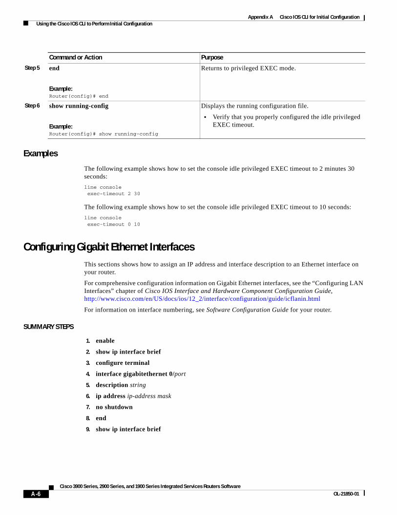
Appendix A Cisco IOS CLI for Initial Configuration Using the Cisco IOS CLI to Perform Initial Configuration
Examples
The following example shows how to set the console idle privileged EXEC timeout to 2 minutes 30 seconds:
line console exec-timeout 2 30
The following example shows how to set the console idle privileged EXEC timeout to 10 seconds:
line console exec-timeout 0 10
Configuring Gigabit Ethernet InterfacesThis sections shows how to assign an IP address and interface description to an Ethernet interface on your router.
For comprehensive configuration information on Gigabit Ethernet interfaces, see the “Configuring LAN Interfaces” chapter of Cisco IOS Interface and Hardware Component Configuration Guide, http://www.cisco.com/en/US/docs/ios/12_2/interface/configuration/guide/icflanin.html
For information on interface numbering, see Software Configuration Guide for your router.
SUMMARY STEPS
1. enable
2. show ip interface brief
3. configure terminal
4. interface gigabitethernet 0/port
5. description string
6. ip address ip-address mask
7. no shutdown
8. end
9. show ip interface brief
Step 5 end
Example:Router(config)# end
Returns to privileged EXEC mode.
Step 6 show running-config
Example:Router(config)# show running-config
Displays the running configuration file.
• Verify that you properly configured the idle privileged EXEC timeout.
Command or Action Purpose
A-6Cisco 3900 Series, 2900 Series, and 1900 Series Integrated Services Routers Software
OL-21850-01

Appendix A Cisco IOS CLI for Initial Configuration Using the Cisco IOS CLI to Perform Initial Configuration
DETAILED STEPS
Command or Action Purpose
Step 1 enable
Example:Router> enable
Enables privileged EXEC mode.
• Enter your password if prompted.
Step 2 show ip interface brief
Example:Router# show ip interface brief
Displays a brief status of the interfaces that are configured for IP.
• Learn which type of Ethernet interface is on your router.
Step 3 configure terminal
Example:Router# configure terminal
Enters global configuration mode.
Step 4 interface gigabitethernet 0/port
Example:Router(config)# interface gigabitethernet 0/0
Specifies the gigabit Ethernet interface and enters interface configuration mode.
Note For information on interface numbering, see Software Configuration Guide.
Step 5 description string
Example:Router(config-if)# description GE int to 2nd floor south wing
(Optional) Adds a description to an interface configuration.
• The description helps you remember what is attached to this interface. The description can be useful for troubleshooting.
Step 6 ip address ip-address mask
Example:Router(config-if)# ip address 172.16.74.3 255.255.255.0
Sets a primary IP address for an interface.
Step 7 no shutdown
Example:Router(config-if)# no shutdown
Enables an interface.
Step 8 end
Example:Router(config)# end
Returns to privileged EXEC mode.
Step 9 show ip interface brief
Example:Router# show ip interface brief
Displays a brief status of the interfaces that are configured for IP.
• Verify that the Ethernet interfaces are up and configured correctly.
A-7Cisco 3900 Series, 2900 Series, and 1900 Series Integrated Services Routers Software
OL-21850-01
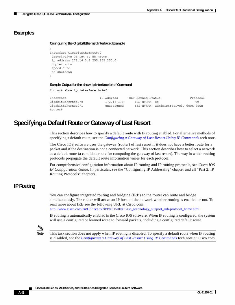
Appendix A Cisco IOS CLI for Initial Configuration Using the Cisco IOS CLI to Perform Initial Configuration
Examples
Configuring the GigabitEthernet Interface: Example! interface GigabitEthernet0/0 description GE int to HR group ip address 172.16.3.3 255.255.255.0 duplex auto speed auto no shutdown!
Sample Output for the show ip interface brief CommandRouter# show ip interface brief
Interface IP-Address OK? Method Status ProtocolGigabitEthernet0/0 172.16.3.3 YES NVRAM up upGigabitEthernet0/1 unassigned YES NVRAM administratively down downRouter#
Specifying a Default Route or Gateway of Last ResortThis section describes how to specify a default route with IP routing enabled. For alternative methods of specifying a default route, see the Configuring a Gateway of Last Resort Using IP Commands tech note.
The Cisco IOS software uses the gateway (router) of last resort if it does not have a better route for a packet and if the destination is not a connected network. This section describes how to select a network as a default route (a candidate route for computing the gateway of last resort). The way in which routing protocols propagate the default route information varies for each protocol.
For comprehensive configuration information about IP routing and IP routing protocols, see Cisco IOS IP Configuration Guide. In particular, see the “Configuring IP Addressing” chapter and all “Part 2: IP Routing Protocols” chapters.
IP Routing
You can configure integrated routing and bridging (IRB) so the router can route and bridge simultaneously. The router will act as an IP host on the network whether routing is enabled or not. To read more about IRB see the following URL at Cisco.com: http://www.cisco.com/en/US/tech/tk389/tk815/tk855/tsd_technology_support_sub-protocol_home.html
IP routing is automatically enabled in the Cisco IOS software. When IP routing is configured, the system will use a configured or learned route to forward packets, including a configured default route.
Note This task section does not apply when IP routing is disabled. To specify a default route when IP routing is disabled, see the Configuring a Gateway of Last Resort Using IP Commands tech note at Cisco.com.
A-8Cisco 3900 Series, 2900 Series, and 1900 Series Integrated Services Routers Software
OL-21850-01

Appendix A Cisco IOS CLI for Initial Configuration Using the Cisco IOS CLI to Perform Initial Configuration
Default Routes
A router might not be able to determine the routes to all other networks. To provide complete routing capability, the common practice is to use some routers as smart routers and give the remaining routers default routes to the smart router. (Smart routers have routing table information for the entire internetwork.) These default routes can be passed along dynamically, or can be configured into the individual routers.
Most dynamic interior routing protocols include a mechanism for causing a smart router to generate dynamic default information that is then passed along to other routers.
Default Network
If a router has an interface that is directly connected to the specified default network, the dynamic routing protocols running on the router will generate or source a default route. In the case of RIP, the router will advertise the pseudo network 0.0.0.0. In the case of IGRP, the network itself is advertised and flagged as an exterior route.
A router that is generating the default for a network also may need a default of its own. One way a router can generate its own default is to specify a static route to the network 0.0.0.0 through the appropriate device.
Gateway of Last Resort
When default information is being passed along through a dynamic routing protocol, no further configuration is required. The system periodically scans its routing table to choose the optimal default network as its default route. In the case of RIP, there is only one choice, network 0.0.0.0. In the case of IGRP, there might be several networks that can be candidates for the system default. The Cisco IOS software uses both administrative distance and metric information to determine the default route (gateway of last resort). The selected default route appears in the gateway of last resort display of the show ip route EXEC command.
If dynamic default information is not being passed to the software, candidates for the default route are specified with the ip default-network global configuration command. In this usage, the ip default-network command takes an unconnected network as an argument. If this network appears in the routing table from any source (dynamic or static), it is flagged as a candidate default route and is a possible choice as the default route.
If the router has no interface on the default network, but does have a route to it, it considers this network as a candidate default path. The route candidates are examined and the best one is chosen, based on administrative distance and metric. The gateway to the best default path becomes the gateway of last resort.
SUMMARY STEPS
1. enable
2. configure terminal
3. ip routing
4. ip route dest-prefix mask next-hop-ip-address [admin-distance] [permanent]
5. ip default-network network-number or ip route dest-prefix mask next-hop-ip-address
A-9Cisco 3900 Series, 2900 Series, and 1900 Series Integrated Services Routers Software
OL-21850-01

Appendix A Cisco IOS CLI for Initial Configuration Using the Cisco IOS CLI to Perform Initial Configuration
6. end
7. show ip route
DETAILED STEPS
Command or Action Purpose
Step 1 enable
Example:Router> enable
Enables privileged EXEC mode.
• Enter your password if prompted.
Step 2 configure terminal
Example:Router# configure terminal
Enters global configuration mode.
Step 3 ip routing
Example:Router(config)# ip routing
Enables IP routing.
Step 4 ip route dest-prefix mask next-hop-ip-address [admin-distance] [permanent]
Example:Router(config)# ip route 192.168.24.0 255.255.255.0 172.28.99.2
Establishes a static route.
Step 5 ip default-network network-number
or
ip route dest-prefix mask next-hop-ip-address
Example:Router(config)# ip default-network 192.168.24.0
Example:Router(config)# ip route 0.0.0.0 0.0.0.0 172.28.99.1
Selects a network as a candidate route for computing the gateway of last resort.
Creates a static route to network 0.0.0.0 0.0.0.0 for computing the gateway of last resort.
Step 6 end
Example:Router(config)# end
Returns to privileged EXEC mode.
Step 7 show ip route
Example:Router# show ip route
Displays the current routing table information.
• Verify that the gateway of last resort is set.
A-10Cisco 3900 Series, 2900 Series, and 1900 Series Integrated Services Routers Software
OL-21850-01

Appendix A Cisco IOS CLI for Initial Configuration Using the Cisco IOS CLI to Perform Initial Configuration
Examples
Specifying a Default Route: Example!ip routing!ip route 192.168.24.0 255.255.255.0 172.28.99.2!ip default-network 192.168.24.0!
Sample Output for the show ip route CommandRouter# show ip route
Codes: C - connected, S - static, I - IGRP, R - RIP, M - mobile, B - BGP D - EIGRP, EX - EIGRP external, O - OSPF, IA - OSPF inter area E1 - OSPF external type 1, E2 - OSPF external type 2, E - EGP i - IS-IS, L1 - IS-IS level-1, L2 - IS-IS level-2, * - candidate default Gateway of last resort is 172.28.99.2 to network 192.168.24.0 172.24.0.0 255.255.255.0 is subnetted, 1 subnetsC 172.24.192.0 is directly connected, GigaEthernet0S 172.24.0.0 255.255.0.0 [1/0] via 172.28.99.0 S* 192.168.24.0 [1/0] via 172.28.99.2 172.16.0.0 255.255.255.0 is subnetted, 1 subnetsC 172.16.99.0 is directly connected, GigaEthernet1Router#
Configuring Virtual Terminal Lines for Remote Console AccessVirtual terminal (vty) lines are used to allow remote access to the router. This section shows you how to configure the virtual terminal lines with a password, so that only authorized users can remotely access the router.
The router has five virtual terminal lines by default. However, you can create additional virtual terminal lines as described in the Cisco IOS Terminal Services Configuration Guide, Release 12.4. See the Configuring Terminal Operating Characteristics for Dial-In Sessions section.
Line passwords and password encryption is described in the Cisco IOS Security Configuration Guide, Release 12.4. See the Security with Passwords, Privilege Levels, and Login Usernames for CLI Sessions on Networking Devices section. If you want to secure the vty lines with an access list, see Access Control Lists: Overview and Guidelines. Also see the Cisco IOS Password Encryption Facts tech note.
A-11Cisco 3900 Series, 2900 Series, and 1900 Series Integrated Services Routers Software
OL-21850-01

Appendix A Cisco IOS CLI for Initial Configuration Using the Cisco IOS CLI to Perform Initial Configuration
SUMMARY STEPS
1. enable
2. configure terminal
3. line vty line-number [ending-line-number]
4. password password
5. login
6. end
7. show running-config
8. From another network device, attempt to open a Telnet session to the router.
DETAILED STEPS
Command or Action Purpose
Step 1 enable
Example:Router> enable
Enables privileged EXEC mode.
• Enter your password if prompted.
Step 2 configure terminal
Example:Router# configure terminal
Enters global configuration mode.
Step 3 line vty line-number [ending-line-number]
Example:Router(config)# line vty 0 4
Starts the line configuration command collection mode for the virtual terminal lines (vty) for remote console access.
• Make sure that you configure all vty lines on your router.
Note To verify the number of vty lines on your router, use the line vty ? command.
Step 4 password password
Example:Router(config-line)# password guessagain
Specifies a password on a line.
Step 5 login
Example:Router(config-line)# login
Enables password checking at login.
Step 6 end
Example:Router(config-line)# end
Returns to privileged EXEC mode.
A-12Cisco 3900 Series, 2900 Series, and 1900 Series Integrated Services Routers Software
OL-21850-01

Appendix A Cisco IOS CLI for Initial Configuration Using the Cisco IOS CLI to Perform Initial Configuration
Examples
The following example shows how to configure virtual terminal lines with a password:
!line vty 0 4 password guessagain login !
What to Do Next
After you configure the vty lines, follow these steps:
• (Optional) To encrypt the virtual terminal line password, see the “Configuring Passwords and Privileges” chapter in Cisco IOS Security Configuration Guide. Also see the Cisco IOS Password Encryption Facts tech note.
• (Optional) To secure the VTY lines with an access list, see “Part 3: Traffic Filtering and Firewalls” in the Cisco IOS Security Configuration Guide.
Configuring the Auxiliary LineThis section describes how to enter line configuration mode for the auxiliary line. How you configure the auxiliary line depends on your particular implementation of the auxiliary (AUX) port. See the following documents for information on configuring the auxiliary line:
Configuring a Modem on the AUX Port for EXEC Dialin Connectivity, tech note http://www.cisco.com/en/US/tech/tk801/tk36/technologies_tech_note09186a0080094bbc.shtml
Configuring Dialout Using a Modem on the AUX Port, sample configuration http://www.cisco.com/en/US/tech/tk801/tk36/ technologies_configuration_example09186a0080094579.shtml
Configuring AUX-to-AUX Port Async Backup with Dialer Watch, sample configuration http://www.cisco.com/en/US/tech/tk801/tk36/ technologies_configuration_example09186a0080093d2b.shtml
Modem-Router Connection Guide, tech note http://www.cisco.com/en/US/tech/tk801/tk36/technologies_tech_note09186a008009428b.shtml
Step 7 show running-config
Example:Router# show running-config
Displays the running configuration file.
• Verify that you properly configured the virtual terminal lines for remote access.
Step 8 From another network device, attempt to open a Telnet session to the router.
Example:Router# 172.16.74.3 Password:
Verifies that you can remotely access the router and that the virtual terminal line password is correctly configured.
Command or Action Purpose
A-13Cisco 3900 Series, 2900 Series, and 1900 Series Integrated Services Routers Software
OL-21850-01

Appendix A Cisco IOS CLI for Initial Configuration Using the Cisco IOS CLI to Perform Initial Configuration
SUMMARY STEPS
1. enable
2. configure terminal
3. line aux 0
4. See the tech notes and sample configurations to configure the line for your particular implementation of the AUX port.
DETAILED STEPS
Verifying Network ConnectivityThis section describes how to verify network connectivity for your router.
Prerequisites
• Complete all previous configuration tasks in this document.
• The router must be connected to a properly configured network host.
SUMMARY STEPS
1. enable
2. ping [ip-address | hostname]
3. telnet {ip-address | hostname}
Command or Action Purpose
Step 1 enable
Example:Router> enable
Enables privileged EXEC mode.
• Enter your password if prompted.
Step 2 configure terminal
Example:Router# configure terminal
Enters global configuration mode.
Step 3 line aux 0
Example:Router(config)# line aux 0
Starts the line configuration command collection mode for the auxiliary line.
Step 4 See the tech notes and sample configurations to configure the line for your particular implementation of the AUX port.
—
A-14Cisco 3900 Series, 2900 Series, and 1900 Series Integrated Services Routers Software
OL-21850-01

Appendix A Cisco IOS CLI for Initial Configuration Using the Cisco IOS CLI to Perform Initial Configuration
DETAILED STEPS
Examples
The following display shows sample output for the ping command when you ping the IP address 192.168.7.27:
Router# ping
Protocol [ip]:Target IP address: 192.168.7.27 Repeat count [5]:Datagram size [100]:Timeout in seconds [2]:Extended commands [n]:Sweep range of sizes [n]:Type escape sequence to abort.Sending 5, 100-byte ICMP Echos to 192.168.7.27, timeout is 2 seconds:!!!!!Success rate is 100 percent, round-trip min/avg/max = 1/2/4 ms
The following display shows sample output for the ping command when you ping the IP hostname username1:
Router# ping username1
Type escape sequence to abort.Sending 5, 100-byte ICMP Echos to 192.168.7.27, timeout is 2 seconds:!!!!!Success rate is 100 percent, round-trip min/avg/max = 1/3/4 ms
Command or Action Purpose
Step 1 enable
Example:Router> enable
Enables privileged EXEC mode.
• Enter your password if prompted.
Step 2 ping [ip-address | hostname]
Example:Router# ping 172.16.74.5
Diagnoses initial network connectivity.
• To verify connectivity, ping the next hop router or connected host for each configured interface to.
Step 3 telnet {ip-address | hostname}
Example:Router# telnet 10.20.30.40
Logs in to a host that supports Telnet.
• If you want to test the vty line password, perform this step from a different network device, and use your router’s IP address.
A-15Cisco 3900 Series, 2900 Series, and 1900 Series Integrated Services Routers Software
OL-21850-01
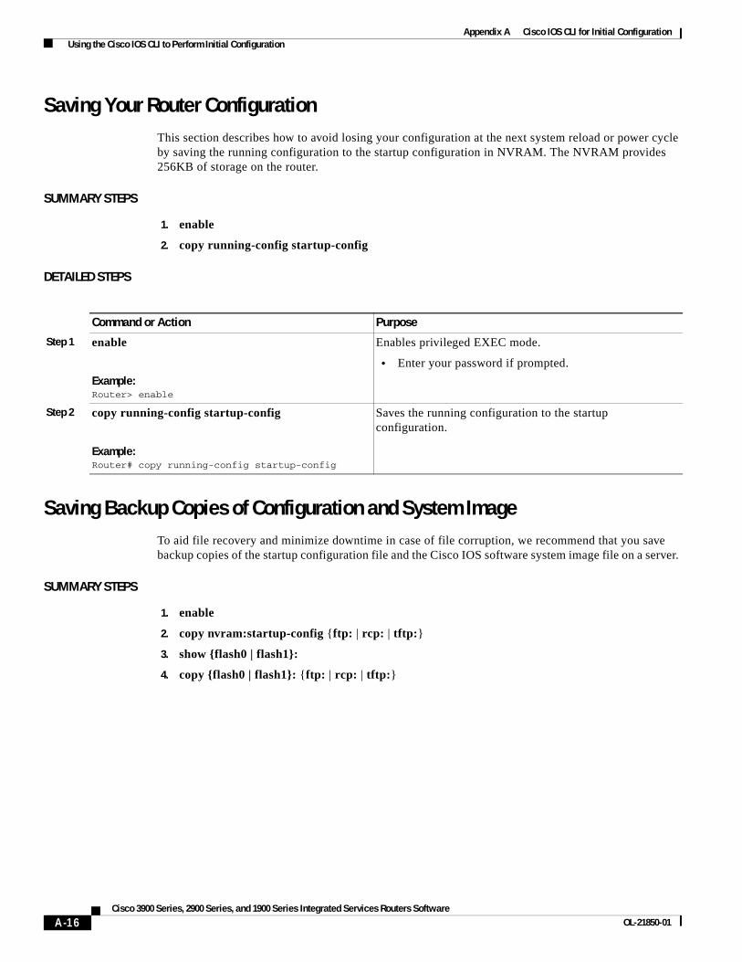
Appendix A Cisco IOS CLI for Initial Configuration Using the Cisco IOS CLI to Perform Initial Configuration
Saving Your Router ConfigurationThis section describes how to avoid losing your configuration at the next system reload or power cycle by saving the running configuration to the startup configuration in NVRAM. The NVRAM provides 256KB of storage on the router.
SUMMARY STEPS
1. enable
2. copy running-config startup-config
DETAILED STEPS
Saving Backup Copies of Configuration and System ImageTo aid file recovery and minimize downtime in case of file corruption, we recommend that you save backup copies of the startup configuration file and the Cisco IOS software system image file on a server.
SUMMARY STEPS
1. enable
2. copy nvram:startup-config {ftp: | rcp: | tftp:}
3. show {flash0 | flash1}:
4. copy {flash0 | flash1}: {ftp: | rcp: | tftp:}
Command or Action Purpose
Step 1 enable
Example:Router> enable
Enables privileged EXEC mode.
• Enter your password if prompted.
Step 2 copy running-config startup-config
Example:Router# copy running-config startup-config
Saves the running configuration to the startup configuration.
A-16Cisco 3900 Series, 2900 Series, and 1900 Series Integrated Services Routers Software
OL-21850-01
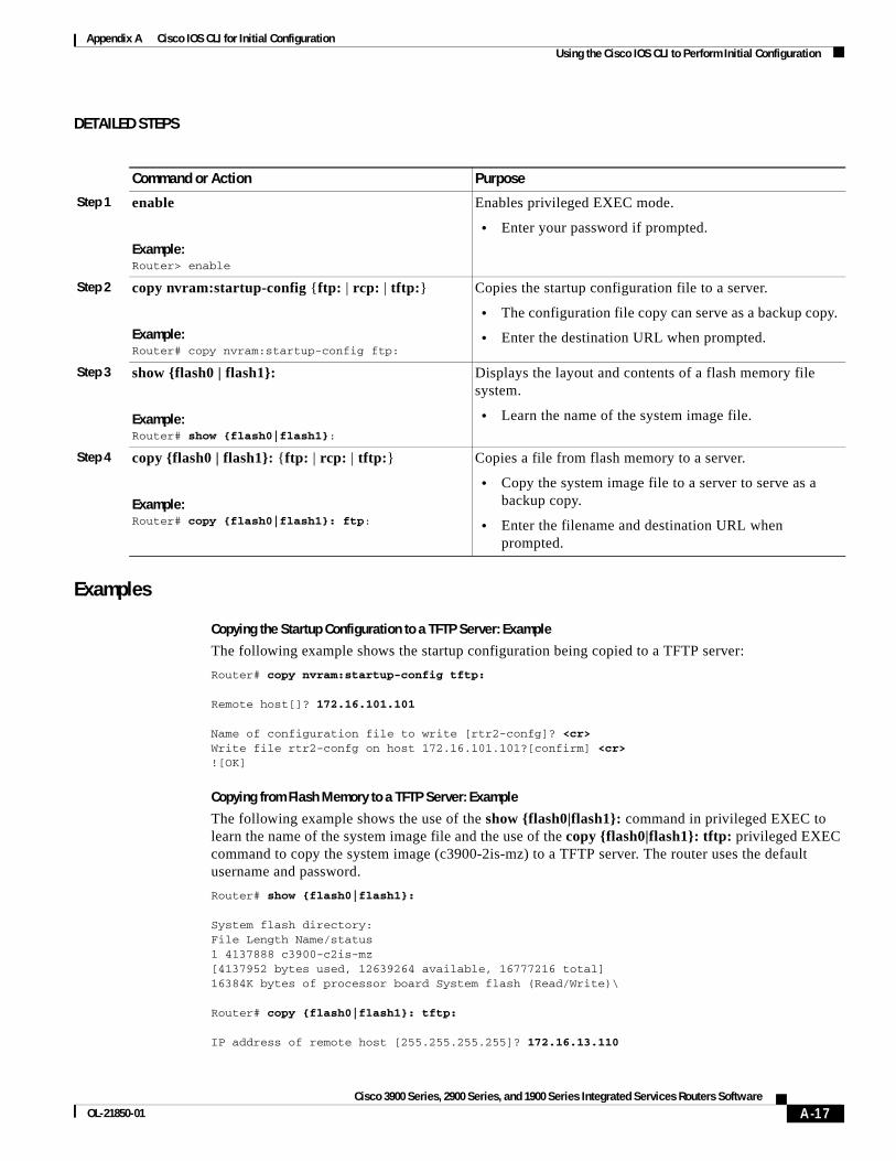
Appendix A Cisco IOS CLI for Initial Configuration Using the Cisco IOS CLI to Perform Initial Configuration
DETAILED STEPS
Examples
Copying the Startup Configuration to a TFTP Server: Example
The following example shows the startup configuration being copied to a TFTP server:
Router# copy nvram:startup-config tftp:
Remote host[]? 172.16.101.101
Name of configuration file to write [rtr2-confg]? <cr> Write file rtr2-confg on host 172.16.101.101?[confirm] <cr> ![OK]
Copying from Flash Memory to a TFTP Server: Example
The following example shows the use of the show {flash0|flash1}: command in privileged EXEC to learn the name of the system image file and the use of the copy {flash0|flash1}: tftp: privileged EXEC command to copy the system image (c3900-2is-mz) to a TFTP server. The router uses the default username and password.
Router# show {flash0|flash1}:
System flash directory:File Length Name/status1 4137888 c3900-c2is-mz[4137952 bytes used, 12639264 available, 16777216 total]16384K bytes of processor board System flash (Read/Write)\
Router# copy {flash0|flash1}: tftp:
IP address of remote host [255.255.255.255]? 172.16.13.110
Command or Action Purpose
Step 1 enable
Example:Router> enable
Enables privileged EXEC mode.
• Enter your password if prompted.
Step 2 copy nvram:startup-config {ftp: | rcp: | tftp:}
Example:Router# copy nvram:startup-config ftp:
Copies the startup configuration file to a server.
• The configuration file copy can serve as a backup copy.
• Enter the destination URL when prompted.
Step 3 show {flash0 | flash1}:
Example:Router# show {flash0|flash1}:
Displays the layout and contents of a flash memory file system.
• Learn the name of the system image file.
Step 4 copy {flash0 | flash1}: {ftp: | rcp: | tftp:}
Example:Router# copy {flash0|flash1}: ftp:
Copies a file from flash memory to a server.
• Copy the system image file to a server to serve as a backup copy.
• Enter the filename and destination URL when prompted.
A-17Cisco 3900 Series, 2900 Series, and 1900 Series Integrated Services Routers Software
OL-21850-01

Appendix A Cisco IOS CLI for Initial Configuration Using the Cisco IOS CLI to Perform Initial Configuration
filename to write on tftp host? c3600-c2is-mz writing c3900-c2is-mz !!!!...successful ftp write.
A-18Cisco 3900 Series, 2900 Series, and 1900 Series Integrated Services Routers Software
OL-21850-01
Appendix A Cisco IOS CLI for Initial Configuration Using the Cisco IOS CLI to Perform Initial Configuration
CCDE, CCENT, CCSI, Cisco Eos, Cisco HealthPresence, Cisco IronPort, the Cisco logo, Cisco Nurse Connect, Cisco Pulse, Cisco SensorBase, Cisco StackPower, Cisco StadiumVision, Cisco TelePresence, Cisco Unified Computing System, Cisco WebEx, DCE, Flip Channels, Flip for Good, Flip Mino, Flipshare (Design), Flip Ultra, Flip Video, Flip Video (Design), Instant Broadband, and Welcome to the Human Network are trademarks; Changing the Way We Work, Live, Play, and Learn, Cisco Capital, Cisco Capital (Design), Cisco:Financed (Stylized), Cisco Store, Flip Gift Card, and One Million Acts of Green are service marks; and Access Registrar, Aironet, AllTouch, AsyncOS, Bringing the Meeting To You, Catalyst, CCDA, CCDP, CCIE, CCIP, CCNA, CCNP, CCSP, CCVP, Cisco, the Cisco Certified Internetwork Expert logo, Cisco IOS, Cisco Lumin, Cisco Nexus, Cisco Press, Cisco Systems, Cisco Systems Capital, the Cisco Systems logo, Cisco Unity, Collaboration Without Limitation, Continuum, EtherFast, EtherSwitch, Event Center, Explorer, Follow Me Browsing, GainMaker, iLYNX, IOS, iPhone, IronPort, the IronPort logo, Laser Link, LightStream, Linksys, MeetingPlace, MeetingPlace Chime Sound, MGX, Networkers, Networking Academy, PCNow, PIX, PowerKEY, PowerPanels, PowerTV, PowerTV (Design), PowerVu, Prisma, ProConnect, ROSA, SenderBase, SMARTnet, Spectrum Expert, StackWise, WebEx, and the WebEx logo are registered trademarks of Cisco Systems, Inc. and/or its affiliates in the United States and certain other countries.
All other trademarks mentioned in this document or website are the property of their respective owners. The use of the word partner does not imply a partnership relationship between Cisco and any other company. (0910R)
Any Internet Protocol (IP) addresses used in this document are not intended to be actual addresses. Any examples, command display output, and figures included in the document are shown for illustrative purposes only. Any use of actual IP addresses in illustrative content is unintentional and coincidental. © 2009-2010 Cisco Systems, Inc. All rights reserved.
A-19Cisco 3900 Series, 2900 Series, and 1900 Series Integrated Services Routers Software
OL-21850-01

Appendix A Cisco IOS CLI for Initial Configuration Using the Cisco IOS CLI to Perform Initial Configuration
A-20Cisco 3900 Series, 2900 Series, and 1900 Series Integrated Services Routers Software
OL-21850-01
Cisco 3900 Series, 2900 Series, and 1900 OL-21850-01
A
P P E N D I X B Using CompactFlash Memory CardsCisco 3900 series, 2900 series, and 1900 series integrated services routers (ISR) use Advanced Capability CompactFlash (CF) external memory to store the system image, configuration files, and some software data files. CF supports True IDE mode and Multi-Word DMA mode.
The following sections explain how to manage directories and files on the CF:
• Requirements and Restrictions, page B-1
• Online Insertion and Removal, page B-2
• How to Format CompactFlash Memory Cards, page B-2
• File Operations on CompactFlash Memory Cards, page B-4
• Directory Operations on a CompactFlash Memory Card, page B-7
Requirements and RestrictionsCompactFlash Support
• Only Advanced Capability CF purchased from Cisco operate in Cisco 3900 series, 2900 series, and 1900 series integrated services routers.
• Legacy CF will not operate in Cisco 3900 series, 2900 series, and 1900 series integrated services routers. When legacy CF is inserted, the following error message appears:
WARNING: Unsupported compact flash detected. Use of this card during normal operation can impact and severely degrade performance of the system. Please use supported compact flash cards only.
Formatting CompactFlash
• Only Class C file systems are supported on Cisco Compact Flash (CF).
• We recommend that you format new CF to initialize a new flash file system. Proper formatting lets ROM monitor recognize and boot the flash memory. The CF can be formatted on an ISR, and files copied to or from any PC that is equipped with a CF memory reader. If you use a PC to format the CF, use the Microsoft File Allocation Table (FAT32) file system.
CompactFlash Slots and Files
• Cisco 3900 series, 2900 series, and 1900 series ISRs have 2 external CF slots.
• CF in Slot0 can store the system image, configuration, and data files. The CF must be present in this slot for the router to boot and perform normal file operations.
B-1Series Integrated Services Routers Software
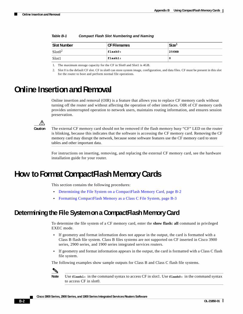
Appendix B Using CompactFlash Memory Cards Online Insertion and Removal
Online Insertion and RemovalOnline insertion and removal (OIR) is a feature that allows you to replace CF memory cards without turning off the router and without affecting the operation of other interfaces. OIR of CF memory cards provides uninterrupted operation to network users, maintains routing information, and ensures session preservation.
Caution The external CF memory card should not be removed if the flash memory busy “CF” LED on the router is blinking, because this indicates that the software is accessing the CF memory card. Removing the CF memory card may disrupt the network, because some software features use the CF memory card to store tables and other important data.
For instructions on inserting, removing, and replacing the external CF memory card, see the hardware installation guide for your router.
How to Format CompactFlash Memory CardsThis section contains the following procedures:
• Determining the File System on a CompactFlash Memory Card, page B-2
• Formatting CompactFlash Memory as a Class C File System, page B-3
Determining the File System on a CompactFlash Memory CardTo determine the file system of a CF memory card, enter the show flash: all command in privileged EXEC mode.
• If geometry and format information does not appear in the output, the card is formatted with a Class B flash file system. Class B files systems are not supported on CF inserted in Cisco 3900 series, 2900 series, and 1900 series integrated services routers.
• If geometry and format information appears in the output, the card is formatted with a Class C flash file system.
The following examples show sample outputs for Class B and Class C flash file systems.
Note Use flash1: in the command syntax to access CF in slot1. Use flash0: in the command syntax to access CF in slot0.
Table B-1 Compact Flash Slot Numbering and Naming
Slot Number CF Filenames Size1
1. The maximum storage capacity for the CF in Slot0 and Slot1 is 4GB.
Slot02
2. Slot 0 is the default CF slot. CF in slot0 can store system image, configuration, and data files. CF must be present in this slot for the router to boot and perform normal file operations.
flash0: 256MB
Slot1 flash1: 0
B-2Cisco 3900 Series, 2900 Series, and 1900 Series Integrated Services Routers Software
OL-21850-01

Appendix B Using CompactFlash Memory Cards How to Format CompactFlash Memory Cards
External Card with Class B Flash File System: Example
The geometry and format information does not appear.
Router# show flash: all
Partition Size Used Free Bank-Size State CopyMode 1 125184K 20390K 104793K 0K Read/WriteDirect
System Compact Flash directory:File Length Name/status addr fcksum ccksum 1 6658376 c29xx-i-mz 0x40 0xE0FF 0xE0FF 2 14221136 c2900-telcoent-mz 0x6599C8 0x5C3D 0x5C3D[20879640 bytes used, 107308776 available, 128188416 total]125184K bytes of ATA System Compact Flash (Read/Write)
Chip information NOT available.
External Card with Class C Flash File System: Example
The geometry and format information is displayed in this format.
Router# show flash: all
-#- --length-- -----date/time------ path1 6658376 Mar 01 2004 04:27:46 c28xx-i-mz
25268224 bytes available (6664192 bytes used)
******** ATA Flash Card Geometry/Format Info ********
ATA CARD GEOMETRY Number of Heads: 4 Number of Cylinders 490 Sectors per Cylinder 32 Sector Size 512 Total Sectors 62720
ATA CARD FORMAT Number of FAT Sectors 31 Sectors Per Cluster 8 Number of Clusters 7796 Number of Data Sectors 62560 Base Root Sector 155 Base FAT Sector 93 Base Data Sector 187
Formatting CompactFlash Memory as a Class C File SystemUse the format flash0: command in privileged EXEC mode to:
• Format CF memory cards with a Class C flash file system
• Remove the files from a CF memory card previously formatted with a Class C flash file system
B-3Cisco 3900 Series, 2900 Series, and 1900 Series Integrated Services Routers Software
OL-21850-01
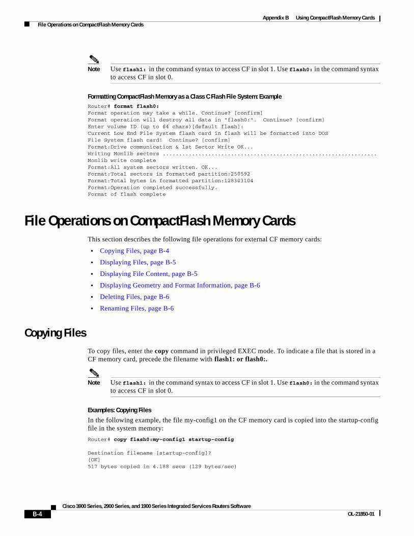
Appendix B Using CompactFlash Memory Cards File Operations on CompactFlash Memory Cards
Note Use flash1: in the command syntax to access CF in slot 1. Use flash0: in the command syntax to access CF in slot 0.
Formatting CompactFlash Memory as a Class C Flash File System: ExampleRouter# format flash0:Format operation may take a while. Continue? [confirm]Format operation will destroy all data in "flash0:". Continue? [confirm]Enter volume ID (up to 64 chars)[default flash]:Current Low End File System flash card in flash will be formatted into DOSFile System flash card! Continue? [confirm]Format:Drive communication & 1st Sector Write OK...Writing Monlib sectors ..................................................................Monlib write completeFormat:All system sectors written. OK...Format:Total sectors in formatted partition:250592Format:Total bytes in formatted partition:128303104Format:Operation completed successfully.Format of flash complete
File Operations on CompactFlash Memory CardsThis section describes the following file operations for external CF memory cards:
• Copying Files, page B-4
• Displaying Files, page B-5
• Displaying File Content, page B-5
• Displaying Geometry and Format Information, page B-6
• Deleting Files, page B-6
• Renaming Files, page B-6
Copying FilesTo copy files, enter the copy command in privileged EXEC mode. To indicate a file that is stored in a CF memory card, precede the filename with flash1: or flash0:.
Note Use flash1: in the command syntax to access CF in slot 1. Use flash0: in the command syntax to access CF in slot 0.
Examples: Copying Files
In the following example, the file my-config1 on the CF memory card is copied into the startup-config file in the system memory:
Router# copy flash0:my-config1 startup-config
Destination filename [startup-config]?[OK]517 bytes copied in 4.188 secs (129 bytes/sec)
B-4Cisco 3900 Series, 2900 Series, and 1900 Series Integrated Services Routers Software
OL-21850-01

Appendix B Using CompactFlash Memory Cards File Operations on CompactFlash Memory Cards
In the following example, the file my-config2 on the CF memory card is copied into the running-config file in the system memory:
Router# copy flash0:my-config2 running-config
Destination filename [running-config]?709 bytes copied in 0.72 secs
Displaying FilesTo display a list of files on a CF memory card, enter the dir flash0: command in privileged EXEC mode.
Note Use flash1: in the command syntax to access CF in slot 1. Use flash0: in the command syntax to access CF in slot 0.
Router# dir flash0:
Directory of flash0:/ 1580 -rw- 6462268 Mar 06 2004 06:14:02 c2900-universalk9-mz.data 3 -rw- 6458388 Mar 01 2004 00:01:24 c2900-universalk9-mz.bin63930368 bytes total (51007488 bytes free)
Displaying File ContentTo display the content of a file that is stored in flash memory, enter the more flash0: command in privileged EXEC mode:
Note Use flash1: in the command syntax to access CF in slot 1. Use flash0: in the command syntax to access CF in slot 0.
Router# more flash0:c29xx-i-mz
00000000: 7F454C46 01020100 00000000 00000000 .ELF .... .... ....00000010: 00020061 00000001 80008000 00000034 ...a .... .... ...400000020: 00000054 20000001 00340020 00010028 ...T ... .4. ...(00000030: 00050008 00000001 0000011C 80008000 .... .... .... ....00000040: 80008000 00628A44 00650EEC 00000007 .... .b.D .e.l ....00000050: 0000011C 0000001B 00000001 00000006 .... .... .... ....00000060: 80008000 0000011C 00004000 00000000 .... .... ..@. ....00000070: 00000000 00000008 00000000 00000021 .... .... .... ...!00000080: 00000001 00000002 8000C000 0000411C .... .... ..@. ..A.00000090: 00000700 00000000 00000000 00000004 .... .... .... ....000000A0: 00000000 00000029 00000001 00000003 .... ...) .... ....000000B0: 8000C700 0000481C 00000380 00000000 ..G. ..H. .... ....000000C0: 00000000 00000004 00000000 0000002F .... .... .... .../000000D0: 00000001 10000003 8000CA80 00004B9C .... .... ..J. ..K.000000E0: 00000020 00000000 00000000 00000008 ... .... .... ....000000F0: 00000000 0000002F 00000001 10000003 .... .../ .... ....00000100: 8000CAA0 00004BBC 00623FA4 00000000 ..J ..K< .b?$ ....00000110: 00000000 00000008 00000000 3C1C8001 .... .... .... <...00000120: 679C4A80 3C018001 AC3DC70C 3C018001 g.J. <... ,=G. <...00000130: AC3FC710 3C018001 AC24C714 3C018001 ,?G. <... ,$G. <...00000140: AC25C718 3C018001 AC26C71C 3C018001 ,%G. <... ,&G. <...00000150: AC27C720 3C018001 AC30C724 3C018001 ,'G <... ,0G$ <...00000160: AC31C728 3C018001 AC32C72C 3C018001 ,1G( <... ,2G, <...--More-- q
B-5Cisco 3900 Series, 2900 Series, and 1900 Series Integrated Services Routers Software
OL-21850-01
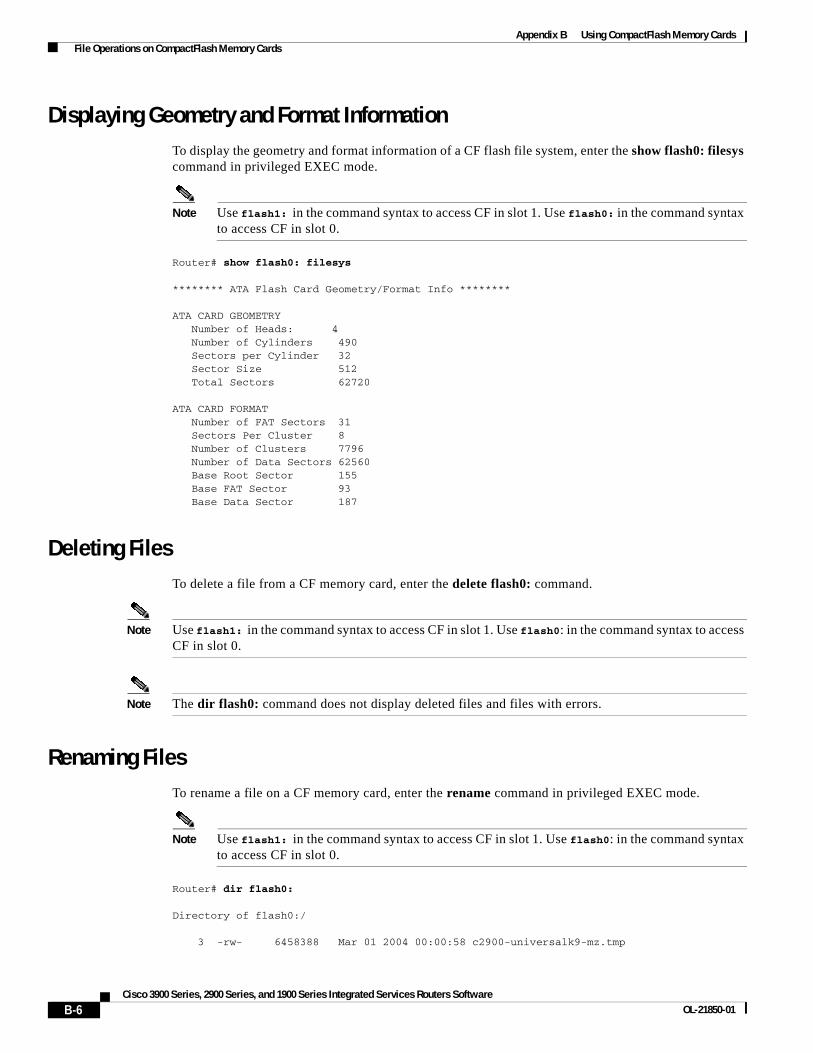
Appendix B Using CompactFlash Memory Cards File Operations on CompactFlash Memory Cards
Displaying Geometry and Format InformationTo display the geometry and format information of a CF flash file system, enter the show flash0: filesys command in privileged EXEC mode.
Note Use flash1: in the command syntax to access CF in slot 1. Use flash0: in the command syntax to access CF in slot 0.
Router# show flash0: filesys
******** ATA Flash Card Geometry/Format Info ********
ATA CARD GEOMETRY Number of Heads: 4 Number of Cylinders 490 Sectors per Cylinder 32 Sector Size 512 Total Sectors 62720
ATA CARD FORMAT Number of FAT Sectors 31 Sectors Per Cluster 8 Number of Clusters 7796 Number of Data Sectors 62560 Base Root Sector 155 Base FAT Sector 93 Base Data Sector 187
Deleting FilesTo delete a file from a CF memory card, enter the delete flash0: command.
Note Use flash1: in the command syntax to access CF in slot 1. Use flash0: in the command syntax to access CF in slot 0.
Note The dir flash0: command does not display deleted files and files with errors.
Renaming FilesTo rename a file on a CF memory card, enter the rename command in privileged EXEC mode.
Note Use flash1: in the command syntax to access CF in slot 1. Use flash0: in the command syntax to access CF in slot 0.
Router# dir flash0:
Directory of flash0:/
3 -rw- 6458388 Mar 01 2004 00:00:58 c2900-universalk9-mz.tmp
B-6Cisco 3900 Series, 2900 Series, and 1900 Series Integrated Services Routers Software
OL-21850-01
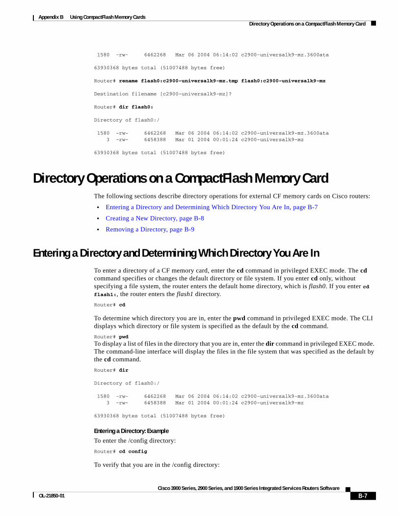
Appendix B Using CompactFlash Memory Cards Directory Operations on a CompactFlash Memory Card
1580 -rw- 6462268 Mar 06 2004 06:14:02 c2900-universalk9-mz.3600ata
63930368 bytes total (51007488 bytes free)
Router# rename flash0:c2900-universalk9-mz.tmp flash0:c2900-universalk9-mz
Destination filename [c2900-universalk9-mz]?
Router# dir flash0:
Directory of flash0:/
1580 -rw- 6462268 Mar 06 2004 06:14:02 c2900-universalk9-mz.3600ata 3 -rw- 6458388 Mar 01 2004 00:01:24 c2900-universalk9-mz
63930368 bytes total (51007488 bytes free)
Directory Operations on a CompactFlash Memory CardThe following sections describe directory operations for external CF memory cards on Cisco routers:
• Entering a Directory and Determining Which Directory You Are In, page B-7
• Creating a New Directory, page B-8
• Removing a Directory, page B-9
Entering a Directory and Determining Which Directory You Are InTo enter a directory of a CF memory card, enter the cd command in privileged EXEC mode. The cd command specifies or changes the default directory or file system. If you enter cd only, without specifying a file system, the router enters the default home directory, which is flash0. If you enter cd flash1:, the router enters the flash1 directory.
Router# cd
To determine which directory you are in, enter the pwd command in privileged EXEC mode. The CLI displays which directory or file system is specified as the default by the cd command.
Router# pwd
To display a list of files in the directory that you are in, enter the dir command in privileged EXEC mode. The command-line interface will display the files in the file system that was specified as the default by the cd command.
Router# dir
Directory of flash0:/
1580 -rw- 6462268 Mar 06 2004 06:14:02 c2900-universalk9-mz.3600ata 3 -rw- 6458388 Mar 01 2004 00:01:24 c2900-universalk9-mz
63930368 bytes total (51007488 bytes free)
Entering a Directory: Example
To enter the /config directory:
Router# cd config
To verify that you are in the /config directory:
B-7Cisco 3900 Series, 2900 Series, and 1900 Series Integrated Services Routers Software
OL-21850-01
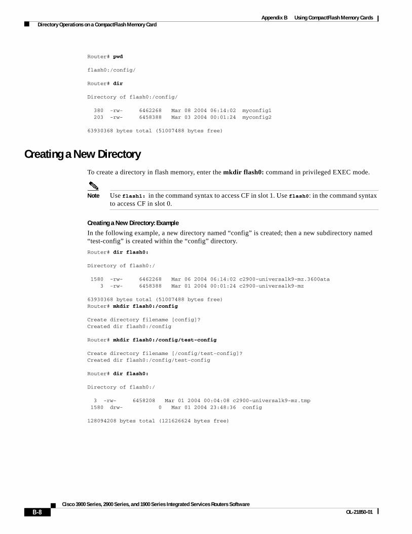
Appendix B Using CompactFlash Memory Cards Directory Operations on a CompactFlash Memory Card
Router# pwd
flash0:/config/
Router# dir
Directory of flash0:/config/
380 -rw- 6462268 Mar 08 2004 06:14:02 myconfig1 203 -rw- 6458388 Mar 03 2004 00:01:24 myconfig2
63930368 bytes total (51007488 bytes free)
Creating a New DirectoryTo create a directory in flash memory, enter the mkdir flash0: command in privileged EXEC mode.
Note Use flash1: in the command syntax to access CF in slot 1. Use flash0: in the command syntax to access CF in slot 0.
Creating a New Directory: Example
In the following example, a new directory named “config” is created; then a new subdirectory named “test-config” is created within the “config” directory.
Router# dir flash0:
Directory of flash0:/
1580 -rw- 6462268 Mar 06 2004 06:14:02 c2900-universalk9-mz.3600ata 3 -rw- 6458388 Mar 01 2004 00:01:24 c2900-universalk9-mz
63930368 bytes total (51007488 bytes free)Router# mkdir flash0:/config
Create directory filename [config]?Created dir flash0:/config
Router# mkdir flash0:/config/test-config
Create directory filename [/config/test-config]?Created dir flash0:/config/test-config
Router# dir flash0:
Directory of flash0:/
3 -rw- 6458208 Mar 01 2004 00:04:08 c2900-universalk9-mz.tmp 1580 drw- 0 Mar 01 2004 23:48:36 config
128094208 bytes total (121626624 bytes free)
B-8Cisco 3900 Series, 2900 Series, and 1900 Series Integrated Services Routers Software
OL-21850-01

Appendix B Using CompactFlash Memory Cards Directory Operations on a CompactFlash Memory Card
Removing a DirectoryTo remove a directory in flash memory, enter the rmdir flash0: command in privileged EXEC mode.
Before you can remove a directory, you must remove all files and subdirectories from the directory.
Note Use flash1: in the command syntax to access CF in slot 1. Use flash0: in the command syntax to access CF in slot 0.
Example: Removing a Directory
In the following example, the subdirectory test-config is removed.
Router# dir
Directory of flash0:/config/
1581 drw- 0 Mar 01 2004 23:50:08 test-config
128094208 bytes total (121626624 bytes free)Router# rmdir flash0:/config/test-config
Remove directory filename [/config/test-config]?Delete flash0:/config/test-config? [confirm]Removed dir flash0:/config/test-configRouter# dir
Directory of flash0:/config/
No files in directory
128094208 bytes total (121630720 bytes free)
B-9Cisco 3900 Series, 2900 Series, and 1900 Series Integrated Services Routers Software
OL-21850-01

Appendix B Using CompactFlash Memory Cards Directory Operations on a CompactFlash Memory Card
CCDE, CCENT, CCSI, Cisco Eos, Cisco HealthPresence, Cisco IronPort, the Cisco logo, Cisco Nurse Connect, Cisco Pulse, Cisco SensorBase, Cisco StackPower, Cisco StadiumVision, Cisco TelePresence, Cisco Unified Computing System, Cisco WebEx, DCE, Flip Channels, Flip for Good, Flip Mino, Flipshare (Design), Flip Ultra, Flip Video, Flip Video (Design), Instant Broadband, and Welcome to the Human Network are trademarks; Changing the Way We Work, Live, Play, and Learn, Cisco Capital, Cisco Capital (Design), Cisco:Financed (Stylized), Cisco Store, Flip Gift Card, and One Million Acts of Green are service marks; and Access Registrar, Aironet, AllTouch, AsyncOS, Bringing the Meeting To You, Catalyst, CCDA, CCDP, CCIE, CCIP, CCNA, CCNP, CCSP, CCVP, Cisco, the Cisco Certified Internetwork Expert logo, Cisco IOS, Cisco Lumin, Cisco Nexus, Cisco Press, Cisco Systems, Cisco Systems Capital, the Cisco Systems logo, Cisco Unity, Collaboration Without Limitation, Continuum, EtherFast, EtherSwitch, Event Center, Explorer, Follow Me Browsing, GainMaker, iLYNX, IOS, iPhone, IronPort, the IronPort logo, Laser Link, LightStream, Linksys, MeetingPlace, MeetingPlace Chime Sound, MGX, Networkers, Networking Academy, PCNow, PIX, PowerKEY, PowerPanels, PowerTV, PowerTV (Design), PowerVu, Prisma, ProConnect, ROSA, SenderBase, SMARTnet, Spectrum Expert, StackWise, WebEx, and the WebEx logo are registered trademarks of Cisco Systems, Inc. and/or its affiliates in the United States and certain other countries.
All other trademarks mentioned in this document or website are the property of their respective owners. The use of the word partner does not imply a partnership relationship between Cisco and any other company. (0910R)
Any Internet Protocol (IP) addresses used in this document are not intended to be actual addresses. Any examples, command display output, and figures included in the document are shown for illustrative purposes only. Any use of actual IP addresses in illustrative content is unintentional and coincidental. © 2009-2010 Cisco Systems, Inc. All rights reserved.
B-10Cisco 3900 Series, 2900 Series, and 1900 Series Integrated Services Routers Software
OL-21850-01

Cisco 3900 Series, 2900 Series, and 1900 OL-21850-01
A
P P E N D I X C Using ROM MonitorThe ROM monitor is accessed during power up or reload when the router does not find a valid system image, the last digit of the boot field in the configuration register is 0, or you enter the Break key sequence during the first 5 seconds after reloading the router.
The following sections describe how to use the ROM monitor in the Cisco 3900 series, 2900 series, 1900 series integrated services routers (ISRs) to manually load a system image or upgrade the system image for disaster, or when there are no TFTP servers or network connections.
• Prerequisites for Using the ROM Monitor, page C-1
• Information About the ROM Monitor, page C-1
• How to Use the ROM Monitor—Typical Tasks, page C-3
• Additional References, page C-27
Prerequisites for Using the ROM MonitorConnect a terminal or PC to the router console port. For help, see the hardware installation guide for your router.
Information About the ROM MonitorBefore using the ROM monitor, you should understand the following concepts:
• ROM Monitor Mode Command Prompt, page C-1
• Why is the Router in ROM Monitor Mode?, page C-2
• When do I use ROM Monitor?, page C-2
• Tips for Using ROM Monitor Commands, page C-2
• Accessibility, page C-3
ROM Monitor Mode Command PromptThe ROM monitor uses the rommon x > command prompt. The x variable begins at 1 and increments each time you press Return or Enter in ROM monitor mode.
C-1Series Integrated Services Routers Software

Appendix C Using ROM Monitor Information About the ROM Monitor
Why is the Router in ROM Monitor Mode?The router boots to ROM monitor mode when one of the following occurs:
• During power up or reload, the router did not find a valid system image.
• The last digit of the boot field in the configuration register is 0 (for example, 0x100 or 0x0).
• The Break key sequence was entered during the first 60 seconds after reloading the router.
To exit ROM monitor mode, see the “Exiting ROM Monitor Mode” section on page C-25.
When do I use ROM Monitor?Use ROM monitor in the following situations:
• Manually loading a system image—You can load a system image without configuring the router to load that image in future system reloads or power-cycles. This can be useful for testing a new system image or for troubleshooting. See the “Loading a System Image (boot)” section on page C-8.
• Upgrading the system image when there are no TFTP servers or network connections, and a direct PC connection to the router console is the only viable option—See information about upgrading the system image in the configuration documentation for your router.
• During troubleshooting if the router crashes and hangs—See the “Troubleshooting Crashes and Hangs (stack, context, frame, sysret, meminfo)” section on page C-20.
• Disaster recovery—Use one of the following methods for recovering the system image or configuration file:
– TFTP download (tftpdnld)—Use this method if you can connect a TFTP server directly to the fixed LAN port on your router. See the “Recovering the System Image (tftpdnld)” section on page C-16.
Note Recovering the system image is different from upgrading the system image. You need to recover the system image if it becomes corrupt or if it is deleted because of a disaster that affects the memory device severely enough to require deleting all data on the memory device in order to load a system image.
Tips for Using ROM Monitor Commands • ROM monitor commands are case sensitive.
• You can halt any ROM monitor command by entering the Break key sequence (Ctrl-Break) on the PC or terminal. The Break key sequence varies, depending on the software on your PC or terminal. If Ctrl-Break does not work, see the Standard Break Key Sequence Combinations During Password Recovery tech note.
• To find out which commands are available on your router and to display command syntax options, see the “Displaying Commands and Command Syntax in ROM Monitor Mode (?, help, -?)” section on page C-7.
C-2Cisco 3900 Series, 2900 Series, and 1900 Series Integrated Services Routers Software
OL-21850-01

Appendix C Using ROM Monitor How to Use the ROM Monitor—Typical Tasks
AccessibilityThis product can be configured using the Cisco command-line interface (CLI). The CLI conforms to accessibility code 508 because it is text based and it relies on a keyboard for navigation. All functions of the router can be configured and monitored through the CLI.
For a complete list of guidelines and Cisco products adherence to accessibility, see the Cisco Accessibility Products document at:
http://www.cisco.com/web/about/responsibility/accessibility/products
How to Use the ROM Monitor—Typical TasksThis section provides the following procedures:
• Entering ROM Monitor Mode, page C-3
• Displaying Commands and Command Syntax in ROM Monitor Mode (?, help, -?), page C-7
• Displaying Files in a File System (dir), page C-8
• Loading a System Image (boot), page C-8
• Modifying the Configuration Register (confreg), page C-13
• Obtaining Information on USB Flash Devices, page C-14
• Modifying the I/O Memory (iomemset), page C-15
• Recovering the System Image (tftpdnld), page C-16
• Troubleshooting Crashes and Hangs (stack, context, frame, sysret, meminfo), page C-20
• Exiting ROM Monitor Mode, page C-25
Note This section does not describe how to perform all possible ROM monitor tasks. Use the command help to perform any tasks that are not described in this document. See the “Displaying Commands and Command Syntax in ROM Monitor Mode (?, help, -?)” section on page C-7.
Entering ROM Monitor ModeThis section provides two ways to enter ROM monitor mode:
• Using the Break Key Sequence to Interrupt the System Reload and Enter ROM Monitor Mode, page C-4
• Setting the Configuration Register to Boot to ROM Monitor Mode, page C-5
Prerequisites
Connect a terminal or PC to the router console port. For help, see the hardware installation guide for your router.
C-3Cisco 3900 Series, 2900 Series, and 1900 Series Integrated Services Routers Software
OL-21850-01

Appendix C Using ROM Monitor How to Use the ROM Monitor—Typical Tasks
Using the Break Key Sequence to Interrupt the System Reload and Enter ROM Monitor Mode
To enter ROM monitor mode by reloading the router and entering the Break key sequence, follow these steps.
SUMMARY STEPS
1. enable
2. reload
3. Press Ctrl-Break.
DETAILED STEPS
Example
Sample Output for the reload CommandUse break key sequence to enter rom monitorRouter# reload
Proceed with reload? [confirm] *Sep 23 15:54:25.871: %SYS-5-RELOAD: Reload requested by console. Reload Reason: Reload command.telnet> send break *** System received an abort due to Break Key ***signal= 0x3, code= 0x0, context= 0x431aaf40PC = 0x4008b5dc, Cause = 0x20, Status Reg = 0x3400c102rommon 1 >
Command or Action Purpose
Step 1 enable
Example:Router> enable
Enables privileged EXEC mode.
• Enter your password if prompted.
Step 2 reload
Example:Router# reload
Reloads the operating system.
Step 3 Press Ctrl-Break.
Example:Router# send break
Interrupts the router reload and enters ROM monitor mode.
• You must perform this step within 60 seconds after you enter the reload command.
• The Break key sequence varies, depending on the software on your PC or terminal. If Ctrl-Break does not work, see the Standard Break Key Sequence Combinations During Password Recovery tech note.
C-4Cisco 3900 Series, 2900 Series, and 1900 Series Integrated Services Routers Software
OL-21850-01
Appendix C Using ROM Monitor How to Use the ROM Monitor—Typical Tasks
Troubleshooting Tips
The Break key sequence varies, depending on the software on your PC or terminal. See the Standard Break Key Sequence Combinations During Password Recovery tech note.
What to Do Next
• Proceed to the “Displaying Commands and Command Syntax in ROM Monitor Mode (?, help, -?)” section on page C-7.
• If you use the Break key sequence to enter ROM monitor mode when the router would otherwise have booted the system image, you can exit ROM monitor mode by doing one of the following:
– Enter the i or reset command, which restarts the booting process and loads the system image.
– Enter the cont command, which continues the booting process and loads the system image.
Setting the Configuration Register to Boot to ROM Monitor Mode
This section describes how to enter ROM monitor mode by setting the configuration register to boot to ROM monitor mode at the next system reload or power-cycle. For more information about the configuration register, see the Changing the Configuration Register Settings document at:
http://www.cisco.com/en/US/docs/routers/access/1800/1841/software/configuration/guide/b_creg.html
Caution Do not set the configuration register by using the config-register 0x0 command after you have set the baud rate. To set the configuration register without affecting the baud rate, use the current configuration register setting by entering the show ver | inc configuration command, and then replacing the last (rightmost) number with a 0 in the configuration register command.
SUMMARY STEPS
1. enable
2. configure terminal
3. config-register 0x0
4. exit
5. write memory
6. reload
C-5Cisco 3900 Series, 2900 Series, and 1900 Series Integrated Services Routers Software
OL-21850-01

Appendix C Using ROM Monitor How to Use the ROM Monitor—Typical Tasks
DETAILED STEPS
Examples
The following example shows how to set the configuration register to boot to ROM monitor mode:
Router>Router> enableRouter# configure terminalEnter configuration commands, one per line. End with CNTL/Z.Router(config)# config-register 0x0Router(config)# exitRouter#*Sep 23 16:01:24.351: %SYS-5-CONFIG_I: Configured from console by consoleRouter# write memoryBuilding configuration...[OK]Router# reloadProceed with reload? [confirm]
Command or Action Purpose
Step 1 enable
Example:Router> enable
Enables privileged EXEC mode.
• Enter your password if prompted.
Step 2 configure terminal
Example:Router# configure terminal
Enters global configuration mode.
Step 3 config-register 0x0
Example:Router(config)# config-register 0x0
Changes the configuration register settings.
• The 0x0 setting forces the router to boot to the ROM monitor at the next system reload.
Step 4 exit
Example:Router(config)# exit
Exits global configuration mode.
Step 5 write memory
Example:Router# write memory
Sets to boot the system image from flash memory.
Step 6 reload
Example:Router# reload
<output deleted>
rommon 1>
Reloads the operating system.
• Because of the 0x0 configuration register setting, the router boots to ROM monitor mode.
C-6Cisco 3900 Series, 2900 Series, and 1900 Series Integrated Services Routers Software
OL-21850-01
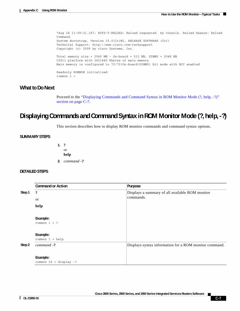
Appendix C Using ROM Monitor How to Use the ROM Monitor—Typical Tasks
*Aug 24 11:09:31.167: %SYS-5-RELOAD: Reload requested by console. Reload Reason: Reload Command.System Bootstrap, Version 15.0(1r)M1, RELEASE SOFTWARE (fc1)Technical Support: http://www.cisco.com/techsupportCopyright (c) 2009 by cisco Systems, Inc.
Total memory size = 2560 MB - On-board = 512 MB, DIMM0 = 2048 MBC2911 platform with 2621440 Kbytes of main memoryMain memory is configured to 72/72(On-board/DIMM0) bit mode with ECC enabled
Readonly ROMMON initializedrommon 1 >
What to Do Next
Proceed to the “Displaying Commands and Command Syntax in ROM Monitor Mode (?, help, -?)” section on page C-7.
Displaying Commands and Command Syntax in ROM Monitor Mode (?, help, -?)This section describes how to display ROM monitor commands and command syntax options.
SUMMARY STEPS
1. ? or help
2. command -?
DETAILED STEPS
Command or Action Purpose
Step 1 ?
or
help
Example:rommon 1 > ?
Example:rommon 1 > help
Displays a summary of all available ROM monitor commands.
Step 2 command -?
Example:rommon 16 > display -?
Displays syntax information for a ROM monitor command.
C-7Cisco 3900 Series, 2900 Series, and 1900 Series Integrated Services Routers Software
OL-21850-01

Appendix C Using ROM Monitor How to Use the ROM Monitor—Typical Tasks
Examples
Sample Output for the help ROM Monitor Commandrommon 1 > help
alias set and display aliases commandboot boot up an external processbreak set/show/clear the breakpointconfreg configuration register utilitycont continue executing a downloaded imagecontext display the context of a loaded imagecookie display contents of cookie PROM in hexdev list the device tabledir list files in file systemframe print out a selected stack framehelp monitor builtin command helphistory monitor command historyiomemset set IO memory percentmeminfo main memory informationrepeat repeat a monitor commandreset system resetrommon-pref select ROMMONset display the monitor variablesshowmon display currently selected ROM monitorstack produce a stack tracesync write monitor environment to NVRAMsysret print out info from last system returntftpdnld tftp image downloadunalias unset an aliasunset unset a monitor variablexmodem x/ymodem image downloadhwpart Read HW resources partition
Displaying Files in a File System (dir)To display a list of the files and directories in the file system, use the dir command, as shown in the following example:
rommon 1 > dir flash0:program load complete, entry point: 0x80803000, size: 0x1b340Directory of flash0:
2 60199000 -rw- c2900-universalk9-mz.SSA.rel114700 1267 -rw- configurationrommon 2 > dir usbflash0:program load complete, entry point: 0x80903000, size: 0x4c400Directory of usbflash0:
2 54212244 -rw- c2900-universalk9-mz.SSA
Loading a System Image (boot)This section describes how to load a system image by using the boot ROM monitor command.
Prerequisites
Determine the filename and location of the system image that you want to load.
C-8Cisco 3900 Series, 2900 Series, and 1900 Series Integrated Services Routers Software
OL-21850-01

Appendix C Using ROM Monitor How to Use the ROM Monitor—Typical Tasks
SUMMARY STEPS
1. boot or boot flash0:[filename] or boot filename tftpserver or boot [filename] or boot usbflash0:[filename]
DETAILED STEPS
Command or Action Purpose
Step 1 boot
or
boot flash0:[filename]
or
boot filename tftpserver 1
or
boot [filename]
or
boot usbflash0:[filename]
Example:ROMMON > boot
Example:ROMMON > boot flash0:
Example:ROMMON > boot someimage 172.16.30.40
Example:ROMMON > boot someimage
Example:ROMMON > boot usbflash0:someimage
1. Cisco 3925E and Cisco 3945E do not support this boot option.
In order, the examples here direct the router to:
• Boot the first image in flash memory.
• Boot the first image or a specified image in flash memory.
Note In IOS, flash0 will be aliased onto flash.
• Boot the specified image over the network from the specified TFTP server (hostname or IP address).
• Boot from the boothelper image because it does not recognize the device ID. This form of the command is used to boot a specified image from a network (TFTP) server.
• Boot the image stored on the USB flash device.
Note Platforms can boot from USB in ROM monitor with or without a compact flash device. It is not necessary to use a bootloader image from the compact flash device. Partitions, such as usbflash0:2:image_name, are not supported on USB flash drives. The boot usbflash<x>: command will boot the first file on the device, if it is a valid image.
You can override the default boothelper image setting by setting the BOOTLDR Monitor environment variable to point to another image. Any system image can be used for this purpose.
• Options for the boot command are -x (load image but do not execute) and -v (verbose).
C-9Cisco 3900 Series, 2900 Series, and 1900 Series Integrated Services Routers Software
OL-21850-01

Appendix C Using ROM Monitor How to Use the ROM Monitor—Typical Tasks
Examples
The following example shows how to load boot flash memory and USB boot flash memory:
rommon 7 > boot flash0:c2900-universalk9-mz.SSAprogram load complete, entry point: 0x80803000, size: 0x1b340
IOS Image Load Test ___________________ Digitally Signed Development Software program load complete, entry point: 0x81000000, size: 0x3968d28Self decompressing the image : ############################################################################################################################################################################################################################################################################################################################################################### [OK]
Smart Init is enabledsmart init is sizing iomem TYPE MEMORY_REQ HWIC Slot 0 0x00200000 HWIC Slot 1 0x00200000 HWIC Slot 2 0x00200000 HWIC Slot 3 0x00200000 PVDM SIMM 0 0x00200000 PVDM SIMM 1 0x00200000 SM Slot 1 0x00600000 ISM Slot 2 0x00600000 Onboard devices & buffer pools 0x0228F000 ----------------------------------------------- TOTAL: 0x03A8F000
Rounded IOMEM up to: 60Mb.Using 5 percent iomem. [60Mb/1024Mb]
Restricted Rights Legend
Use, duplication, or disclosure by the Government issubject to restrictions as set forth in subparagraph(c) of the Commercial Computer Software - RestrictedRights clause at FAR sec. 52.227-19 and subparagraph(c) (1) (ii) of the Rights in Technical Data and ComputerSoftware clause at DFARS sec. 252.227-7013.
cisco Systems, Inc. 170 West Tasman Drive San Jose, California 95134-1706
Cisco IOS Software, C2900SM Software (C2900-UNIVERSALK9-M), Experimental Version 12.4(20090709:004325) [ypatel-secport2 128]Copyright (c) 1986-2009 by Cisco Systems, Inc.Compiled Thu 16-Jul-09 12:55 by ypatel
This product contains cryptographic features and is subject to UnitedStates and local country laws governing import, export, transfer anduse. Delivery of Cisco cryptographic products does not implythird-party authority to import, export, distribute or use encryption.Importers, exporters, distributors and users are responsible forcompliance with U.S. and local country laws. By using this product you
C-10Cisco 3900 Series, 2900 Series, and 1900 Series Integrated Services Routers Software
OL-21850-01

Appendix C Using ROM Monitor How to Use the ROM Monitor—Typical Tasks
agree to comply with applicable laws and regulations. If you are unableto comply with U.S. and local laws, return this product immediately.
A summary of U.S. laws governing Cisco cryptographic products may be found at:http://www.cisco.com/wwl/export/crypto/tool/stqrg.html
If you require further assistance please contact us by sending email [email protected].
Cisco c2911 (revision 1.0) with 987136K/61440K bytes of memory.Processor board ID 3 Gigabit Ethernet interfaces1 terminal lineDRAM configuration is 64 bits wide with parity enabled.255K bytes of non-volatile configuration memory.62960K bytes of USB Flash usbflash0 (Read/Write)248472K bytes of ATA System CompactFlash 0 (Read/Write)248472K bytes of ATA CompactFlash 1 (Read/Write)
Press RETURN to get started!
*Nov 22 09:20:19.839: %LINK-3-UPDOWN: Interface GigabitEthernet0/0, changed state to up*Nov 22 09:20:19.839: %LINK-3-UPDOWN: Interface GigabitEthernet0/1, changed state to down*Nov 22 09:20:19.839: %LINK-3-UPDOWN: Interface GigabitEthernet0/2, changed state to down*Nov 22 09:20:19.839: %LINEPROTO-5-UPDOWN: Line protocol on Interface GigabitEthernet0/0/64, changed state to down*Nov 22 09:20:19.839: %LINEPROTO-t5-UPDOWN: Line protocol on Interface GigabitEthernet0/1/64, changed state Router>rommon 1 > boot usbflash1:c2900-universalk9-mz.SSAprogram load complete, entry point: 0x80803000, size: 0x1b340
IOS Image Load Test ___________________ Digitally Signed Development Software program load complete, entry point: 0x81000000, size: 0x3968d28Self decompressing the image : ############################################################################################################################################################################################################################################################################################################################################################### [OK]
Smart Init is enabledsmart init is sizing iomem TYPE MEMORY_REQ HWIC Slot 0 0x00200000 HWIC Slot 1 0x00200000 HWIC Slot 2 0x00200000 HWIC Slot 3 0x00200000 PVDM SIMM 0 0x00200000 PVDM SIMM 1 0x00200000 SM Slot 1 0x00600000 ISM Slot 2 0x00600000 Onboard devices & buffer pools 0x0228F000 ----------------------------------------------- TOTAL: 0x03A8F000
Rounded IOMEM up to: 60Mb.Using 5 percent iomem. [60Mb/1024Mb]
Restricted Rights Legend
C-11Cisco 3900 Series, 2900 Series, and 1900 Series Integrated Services Routers Software
OL-21850-01

Appendix C Using ROM Monitor How to Use the ROM Monitor—Typical Tasks
Use, duplication, or disclosure by the Government issubject to restrictions as set forth in subparagraph(c) of the Commercial Computer Software - RestrictedRights clause at FAR sec. 52.227-19 and subparagraph(c) (1) (ii) of the Rights in Technical Data and ComputerSoftware clause at DFARS sec. 252.227-7013.
cisco Systems, Inc. 170 West Tasman Drive San Jose, California 95134-1706
Cisco IOS Software, C2900SM Software (C2900-UNIVERSALK9-M), Experimental Version 12.4(20090709:004325) [ypatel-secport2 128]Copyright (c) 1986-2009 by Cisco Systems, Inc.Compiled Thu 16-Jul-09 12:55 by ypatel
This product contains cryptographic features and is subject to UnitedStates and local country laws governing import, export, transfer anduse. Delivery of Cisco cryptographic products does not implythird-party authority to import, export, distribute or use encryption.Importers, exporters, distributors and users are responsible forcompliance with U.S. and local country laws. By using this product youagree to comply with applicable laws and regulations. If you are unableto comply with U.S. and local laws, return this product immediately.
A summary of U.S. laws governing Cisco cryptographic products may be found at:http://www.cisco.com/wwl/export/crypto/tool/stqrg.html
If you require further assistance please contact us by sending email [email protected].
Cisco c2911 (revision 1.0) with 987136K/61440K bytes of memory.Processor board ID 3 Gigabit Ethernet interfaces1 terminal lineDRAM configuration is 64 bits wide with parity enabled.255K bytes of non-volatile configuration memory.62960K bytes of USB Flash usbflash0 (Read/Write)248472K bytes of ATA System CompactFlash 0 (Read/Write)248472K bytes of ATA CompactFlash 1 (Read/Write)
Press RETURN to get started!
*Nov 22 09:20:19.839: %LINK-3-UPDOWN: Interface GigabitEthernet0/0, changed state to up*Nov 22 09:20:19.839: %LINK-3-UPDOWN: Interface GigabitEthernet0/1, changed state to down*Nov 22 09:20:19.839: %LINK-3-UPDOWN: Interface GigabitEthernet0/2, changed state to down*Nov 22 09:20:19.839: %LINEPROTO-5-UPDOWN: Line protocol on Interface GigabitEthernet0/0/64, changed state to down*Nov 22 09:20:19.839: %LINEPROTO-t5-UPDOWN: Line protocol on Interface GigabitEthernet0/1/64, changed state Router>
What to Do Next
If you want to configure the router to load a specified image at the next system reload or power-cycle, see the following documents:
• Booting Commands” chapter of Cisco IOS Configuration Fundamentals Command Reference
• Cisco IOS Configuration Fundamentals Configuration Guide
C-12Cisco 3900 Series, 2900 Series, and 1900 Series Integrated Services Routers Software
OL-21850-01

Appendix C Using ROM Monitor How to Use the ROM Monitor—Typical Tasks
Modifying the Configuration Register (confreg)This section describes how to modify the configuration register by using the confreg ROM monitor command. You can also modify the configuration register setting from the Cisco IOS command-line interface (CLI) by using the config-register command in global configuration mode.
Caution Do not set the configuration register by using the config-register 0x0 command after setting the baud rate. To set the configuration register without affecting the baud rate, use the current configuration register setting by entering the show ver | inc configuration command and then replacing the last (rightmost) number with a 0 in the configuration register command.
Restrictions
The modified configuration register value is automatically written into NVRAM, but the new value does not take effect until you reset or power-cycle the router.
SUMMARY STEPS
1. confreg [value]
DETAILED STEPS
Examples
In the following example, the configuration register is set to boot the system image from flash memory:
rommon 3 > confreg 0x2102
In the following example, no value is entered; therefore, the system prompts for each bit in the register:
rommon 7 > confreg
Configuration Summaryenabled are:console baud: 9600boot: the ROM Monitordo you wish to change the configuration? y/n [n]: y enable "diagnostic mode"? y/n [n]: y enable "use net in IP bcast address"? y/n [n]: y enable "load rom after netboot fails"? y/n [n]: y enable "use all zero broadcast"? y/n [n]: y enable "break/abort has effect"? y/n [n]: y
Command or Action Purpose
Step 1 confreg [value]
Example:rommon > confreg 0x2102
Changes the configuration register settings while in ROM monitor mode.
• Optionally, enter the new hexadecimal value for the configuration register. The value range is from 0x0 to 0xFFFF.
• If you do not enter the value, the router prompts for each bit of the 16-bit configuration register.
C-13Cisco 3900 Series, 2900 Series, and 1900 Series Integrated Services Routers Software
OL-21850-01

Appendix C Using ROM Monitor How to Use the ROM Monitor—Typical Tasks
enable "ignore system config info"? y/n [n]: y change console baud rate? y/n [n]: y enter rate: 0 = 9600, 1 = 4800, 2 = 1200, 3 = 2400 [0]: 0 change the boot characteristics? y/n [n]: y enter to boot:0 = ROM Monitor1 = the boot helper image2-15 = boot system[0]: 0 Configuration Summaryenabled are:diagnostic modeconsole baud: 9600boot: the ROM Monitorrommon 8>
Obtaining Information on USB Flash DevicesThis section describes how to obtain information on USB devices that are installed in the router. For instructions on booting from a USB flash device, see the “Loading a System Image (boot)” section on page C-8.
SUMMARY STEPS
1. dir usbflash [x]:
2. dev
DETAILED STEPS
Examples
Sample Output for the dir usbFlash Commandrommon > dir usbflash0:program load complete, entry point: 0x80903000, size: 0x4c400Directory of usbflash0:
2 54212244 -rw- c2900-universalk9-mz
Sample Output for the dev ROM Monitor Commandrommon 2 > dev
Devices in device table:
Command or Action Purpose
Step 1 dir usbflash [x]:
Example:rommon > dir usbflash0:
Displays the contents of the USB flash device, including directories, files, permissions, and sizes.
• 0—USB flash device inserted in port 0
• 1—USB flash device inserted in port 1
Step 2 dev
Example:ROMMON > dev
Shows the targeted USB flash devices that are inserted in the router and the valid device names that may or may not be currently inserted.
C-14Cisco 3900 Series, 2900 Series, and 1900 Series Integrated Services Routers Software
OL-21850-01
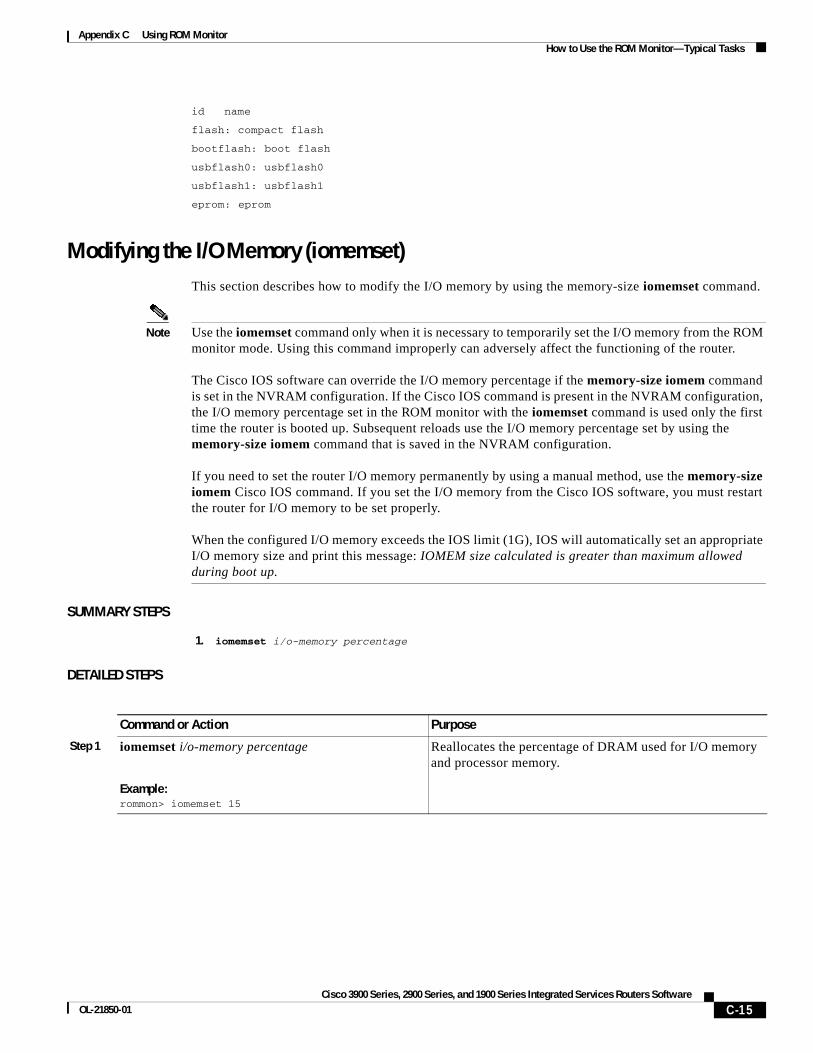
Appendix C Using ROM Monitor How to Use the ROM Monitor—Typical Tasks
id name
flash: compact flash
bootflash: boot flash
usbflash0: usbflash0
usbflash1: usbflash1
eprom: eprom
Modifying the I/O Memory (iomemset)This section describes how to modify the I/O memory by using the memory-size iomemset command.
Note Use the iomemset command only when it is necessary to temporarily set the I/O memory from the ROM monitor mode. Using this command improperly can adversely affect the functioning of the router. The Cisco IOS software can override the I/O memory percentage if the memory-size iomem command is set in the NVRAM configuration. If the Cisco IOS command is present in the NVRAM configuration, the I/O memory percentage set in the ROM monitor with the iomemset command is used only the first time the router is booted up. Subsequent reloads use the I/O memory percentage set by using the memory-size iomem command that is saved in the NVRAM configuration. If you need to set the router I/O memory permanently by using a manual method, use the memory-size iomem Cisco IOS command. If you set the I/O memory from the Cisco IOS software, you must restart the router for I/O memory to be set properly. When the configured I/O memory exceeds the IOS limit (1G), IOS will automatically set an appropriate I/O memory size and print this message: IOMEM size calculated is greater than maximum allowed during boot up.
SUMMARY STEPS
1. iomemset i/o-memory percentage
DETAILED STEPS
Command or Action Purpose
Step 1 iomemset i/o-memory percentage
Example:rommon> iomemset 15
Reallocates the percentage of DRAM used for I/O memory and processor memory.
C-15Cisco 3900 Series, 2900 Series, and 1900 Series Integrated Services Routers Software
OL-21850-01
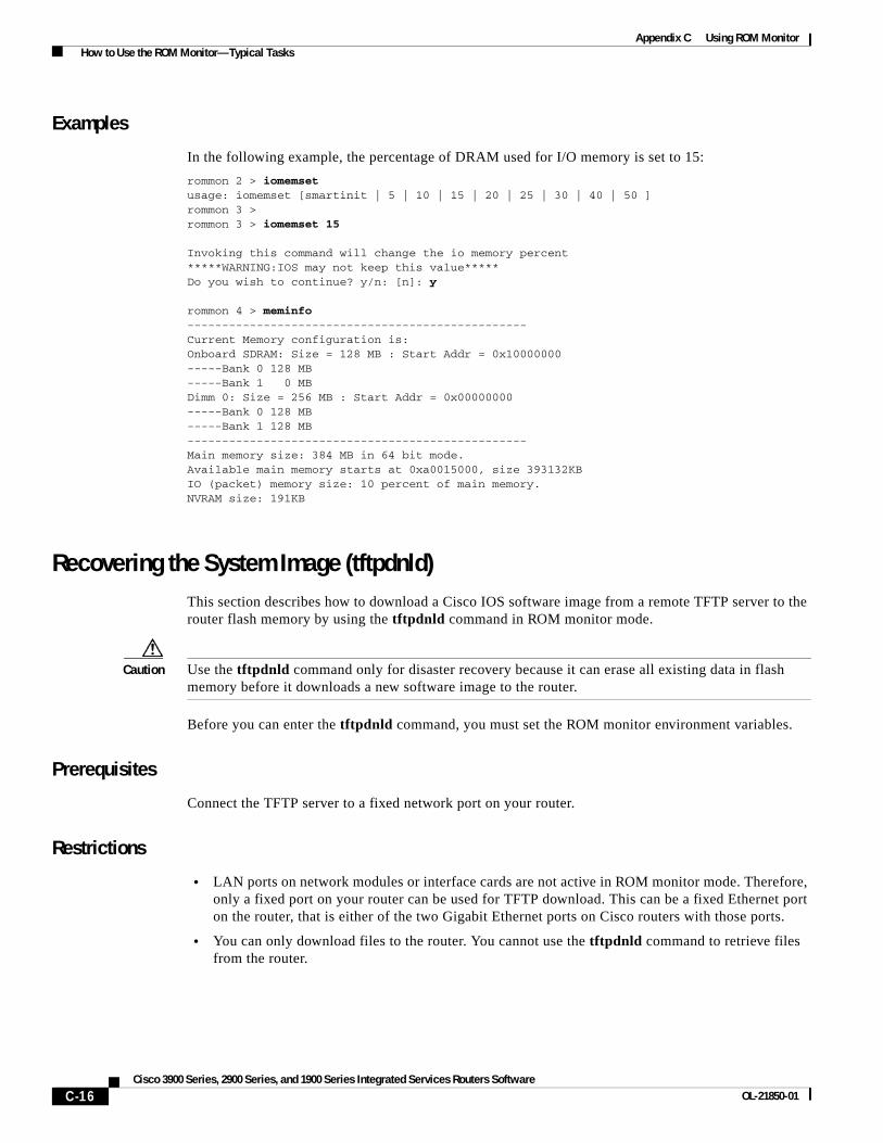
Appendix C Using ROM Monitor How to Use the ROM Monitor—Typical Tasks
Examples
In the following example, the percentage of DRAM used for I/O memory is set to 15:
rommon 2 > iomemset usage: iomemset [smartinit | 5 | 10 | 15 | 20 | 25 | 30 | 40 | 50 ] rommon 3 > rommon 3 > iomemset 15 Invoking this command will change the io memory percent *****WARNING:IOS may not keep this value***** Do you wish to continue? y/n: [n]: y
rommon 4 > meminfo -------------------------------------------------Current Memory configuration is:Onboard SDRAM: Size = 128 MB : Start Addr = 0x10000000-----Bank 0 128 MB-----Bank 1 0 MBDimm 0: Size = 256 MB : Start Addr = 0x00000000-----Bank 0 128 MB-----Bank 1 128 MB-------------------------------------------------Main memory size: 384 MB in 64 bit mode.Available main memory starts at 0xa0015000, size 393132KBIO (packet) memory size: 10 percent of main memory.NVRAM size: 191KB
Recovering the System Image (tftpdnld)This section describes how to download a Cisco IOS software image from a remote TFTP server to the router flash memory by using the tftpdnld command in ROM monitor mode.
Caution Use the tftpdnld command only for disaster recovery because it can erase all existing data in flash memory before it downloads a new software image to the router.
Before you can enter the tftpdnld command, you must set the ROM monitor environment variables.
Prerequisites
Connect the TFTP server to a fixed network port on your router.
Restrictions
• LAN ports on network modules or interface cards are not active in ROM monitor mode. Therefore, only a fixed port on your router can be used for TFTP download. This can be a fixed Ethernet port on the router, that is either of the two Gigabit Ethernet ports on Cisco routers with those ports.
• You can only download files to the router. You cannot use the tftpdnld command to retrieve files from the router.
C-16Cisco 3900 Series, 2900 Series, and 1900 Series Integrated Services Routers Software
OL-21850-01

Appendix C Using ROM Monitor How to Use the ROM Monitor—Typical Tasks
SUMMARY STEPS
1. IP_ADDRESS=ip_address
2. IP_SUBNET_MASK=ip_address
3. DEFAULT_GATEWAY=ip_address
4. TFTP_SERVER=ip_address
5. TFTP_FILE=[directory-path/]filename
6. GE_PORT=[0 | 1 | 2]
7. GE_SPEED_MODE=[0 | 1 | 2 | 3 | 4 | 5]
8. TFTP_MEDIA_TYPE=[0 | 1]
9. TFTP_CHECKSUM=[0 | 1]
10. TFTP_DESTINATION=[flash0: | flash1: | usbflash0: | usbflash1:]
11. TFTP_MACADDR=MAC_address
12. TFTP_RETRY_COUNT=retry_times
13. TFTP_TIMEOUT=time
14. TFTP_VERBOSE=setting
15. set
16. tftpdnld [-h] [-r]
17. y
DETAILED STEPS
Command or Action Purpose
Step 1 IP_ADDRESS=ip_address
Example:rommon > IP_ADDRESS=172.16.23.32
Sets the IP address of the router.
Step 2 IP_SUBNET_MASK=ip_address
Example:rommon > IP_SUBNET_MASK=255.255.255.224
Sets the subnet mask of the router.
Step 3 DEFAULT_GATEWAY=ip_address
Example:rommon > DEFAULT_GATEWAY=172.16.23.40
Sets the default gateway of the router.
Step 4 TFTP_SERVER=ip_address
Example:rommon > TFTP_SERVER=172.16.23.33
Sets the TFTP server from which the software is downloaded.
C-17Cisco 3900 Series, 2900 Series, and 1900 Series Integrated Services Routers Software
OL-21850-01

Appendix C Using ROM Monitor How to Use the ROM Monitor—Typical Tasks
Step 5 TFTP_FILE=[directory-path/]filename
Example:rommon > TFTP_FILE=archive/rel22/c2801-i-mz
Sets the name and location of the file that is downloaded to the router.
Step 6 GE_PORT=[0 | 1 | 2]
Example:rommon > GE_PORT=0
(Optional) Sets the input port to use one of the Gigabit Ethernet ports. The default is 0.
Step 7 GE_SPEED_MODE=[0 | 1 | 2 | 3 | 4 | 5]
Example:rommon > GE_SPEED_MODE=3
(Optional) Sets the Gigabit Ethernet port speed mode, with these options:
• 0—10 Mbps, half-duplex
• 1—10 Mbps, full-duplex
• 2—100 Mbps, half-duplex
• 3—100 Mbps, full-duplex
• 4—1 Gbps, full-duplex
• 5—Automatic selection (default)
Step 8 TFTP_MEDIA_TYPE=[0 | 1]
Example:rommon > MEDIA_TYPE=1
(Optional) Sets the Gigabit Ethernet connection media type, RJ-45 (0) or SFP (1). Small form-factor pluggable (SFP) mode is applicable only if GE_PORT=0 (gig 0/0); RJ-45 mode is available on both gig 0/0 and gig 0/1 (GE_PORT = 0 or 1). The default is 0.
Step 9 TFTP_CHECKSUM=[0 | 1]
Example:rommon > TFTP_CHECKSUM=0
(Optional) Determines whether the router performs a checksum test on the downloaded image.
• 1—Checksum test is performed (default).
• 0—No checksum test is performed.
Step 10 TFTP_DESTINATION=[flash0: | flash1: | usbflash0: | usbflash1:]
Example:rommon > TFTP_DESTINATION=usbflash0:
(Optional) Designates the targeted flash device as compact flash or USB flash.
• flash0:—Compact flash device in port 0(default)
• flash1:—Compact flash device in port 1
• usbflash0:—USB flash device inserted in port 0
• usbflash1:—USB flash device inserted in port 1
Step 11 TFTP_MACADDR=MAC_address
Example:rommon > TFTP_MACADDR=000e.8335.f360
(Optional) Sets the Media Access Controller (MAC) address for this router.
Step 12 TFTP_RETRY_COUNT=retry_times
Example:rommon > TFTP_RETRY_COUNT=10
(Optional) Sets the number of times that the router attempts Address Resolution Protocol (ARP) and TFTP download. The default is 18.
Command or Action Purpose
C-18Cisco 3900 Series, 2900 Series, and 1900 Series Integrated Services Routers Software
OL-21850-01
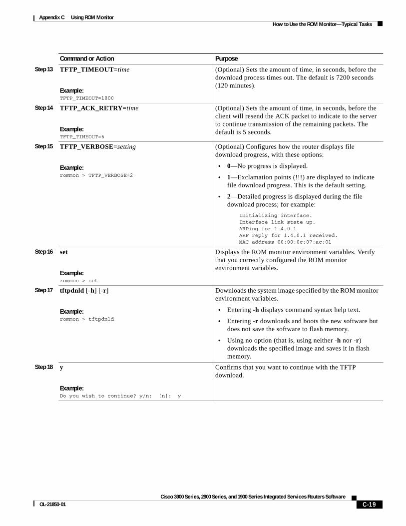
Appendix C Using ROM Monitor How to Use the ROM Monitor—Typical Tasks
Step 13 TFTP_TIMEOUT=time
Example:TFTP_TIMEOUT=1800
(Optional) Sets the amount of time, in seconds, before the download process times out. The default is 7200 seconds (120 minutes).
Step 14 TFTP_ACK_RETRY=time
Example:TFTP_TIMEOUT=6
(Optional) Sets the amount of time, in seconds, before the client will resend the ACK packet to indicate to the server to continue transmission of the remaining packets. The default is 5 seconds.
Step 15 TFTP_VERBOSE=setting
Example:rommon > TFTP_VERBOSE=2
(Optional) Configures how the router displays file download progress, with these options:
• 0—No progress is displayed.
• 1—Exclamation points (!!!) are displayed to indicate file download progress. This is the default setting.
• 2—Detailed progress is displayed during the file download process; for example:
Initializing interface.Interface link state up.ARPing for 1.4.0.1ARP reply for 1.4.0.1 received. MAC address 00:00:0c:07:ac:01
Step 16 set
Example:rommon > set
Displays the ROM monitor environment variables. Verify that you correctly configured the ROM monitor environment variables.
Step 17 tftpdnld [-h] [-r]
Example:rommon > tftpdnld
Downloads the system image specified by the ROM monitor environment variables.
• Entering -h displays command syntax help text.
• Entering -r downloads and boots the new software but does not save the software to flash memory.
• Using no option (that is, using neither -h nor -r) downloads the specified image and saves it in flash memory.
Step 18 y
Example:Do you wish to continue? y/n: [n]: y
Confirms that you want to continue with the TFTP download.
Command or Action Purpose
C-19Cisco 3900 Series, 2900 Series, and 1900 Series Integrated Services Routers Software
OL-21850-01
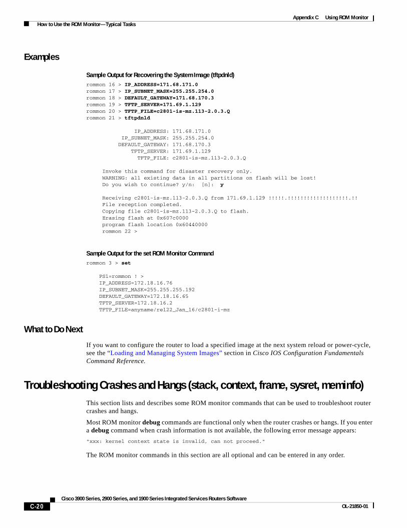
Appendix C Using ROM Monitor How to Use the ROM Monitor—Typical Tasks
Examples
Sample Output for Recovering the System Image (tftpdnld)rommon 16 > IP_ADDRESS=171.68.171.0 rommon 17 > IP_SUBNET_MASK=255.255.254.0 rommon 18 > DEFAULT_GATEWAY=171.68.170.3 rommon 19 > TFTP_SERVER=171.69.1.129 rommon 20 > TFTP_FILE=c2801-is-mz.113-2.0.3.Q rommon 21 > tftpdnld
IP_ADDRESS: 171.68.171.0 IP_SUBNET_MASK: 255.255.254.0 DEFAULT_GATEWAY: 171.68.170.3 TFTP_SERVER: 171.69.1.129 TFTP_FILE: c2801-is-mz.113-2.0.3.Q
Invoke this command for disaster recovery only. WARNING: all existing data in all partitions on flash will be lost! Do you wish to continue? y/n: [n]: y
Receiving c2801-is-mz.113-2.0.3.Q from 171.69.1.129 !!!!!.!!!!!!!!!!!!!!!!!!!.!! File reception completed. Copying file c2801-is-mz.113-2.0.3.Q to flash. Erasing flash at 0x607c0000 program flash location 0x60440000 rommon 22 >
Sample Output for the set ROM Monitor Commandrommon 3 > set
PS1=rommon ! > IP_ADDRESS=172.18.16.76 IP_SUBNET_MASK=255.255.255.192 DEFAULT_GATEWAY=172.18.16.65 TFTP_SERVER=172.18.16.2 TFTP_FILE=anyname/rel22_Jan_16/c2801-i-mz
What to Do Next
If you want to configure the router to load a specified image at the next system reload or power-cycle, see the “Loading and Managing System Images” section in Cisco IOS Configuration Fundamentals Command Reference.
Troubleshooting Crashes and Hangs (stack, context, frame, sysret, meminfo)This section lists and describes some ROM monitor commands that can be used to troubleshoot router crashes and hangs.
Most ROM monitor debug commands are functional only when the router crashes or hangs. If you enter a debug command when crash information is not available, the following error message appears:
"xxx: kernel context state is invalid, can not proceed."
The ROM monitor commands in this section are all optional and can be entered in any order.
C-20Cisco 3900 Series, 2900 Series, and 1900 Series Integrated Services Routers Software
OL-21850-01
Appendix C Using ROM Monitor How to Use the ROM Monitor—Typical Tasks
Router Crashes
A router or system crash is a situation in which the system detects an unrecoverable error and restarts itself. The errors that cause crashes are typically detected by processor hardware, which automatically branches to special error-handling code in the ROM monitor. The ROM monitor identifies the error, prints a message, saves information about the failure, and restarts the system. For detailed information about troubleshooting crashes, see the Troubleshooting Router Crashes and Understanding Software-forced Crashes tech notes.
Router Hangs
A router or system hang is a situation in which the system does not respond to input at the console port or to queries sent from the network, such as Telnet and Simple Network Management Protocol (SNMP).
Router hangs occur when:
• The console does not respond
• Traffic does not pass through the router
Router hangs are discussed in detail in the Troubleshooting Router Hangs tech note.
ROM Monitor Console Communication Failure
Under certain mis-configuration situations, it can be impossible to establish a console connection with the router due to a speed mismatch or other incompatibility. The most obvious symptom is erroneous characters in the console display.
If a ROM monitor failure of this type occurs, you may need to change a jumper setting on the motherboard so that the router can boot for troubleshooting. Procedures for accessing the motherboard and jumper locations are described in the installation of internal components section of the hardware installation document for your router.
The jumper to be changed is DUART DFLT, which sets the console connection data rate to 9600 regardless of user configuration. The jumper forces the data rate to a known good value.
Restrictions
Do not manually reload or power-cycle the router unless reloading or power cycling is required for troubleshooting a router crash. The system reload or power-cycle can cause important information to be lost that is needed for determining the root cause of the problem.
SUMMARY STEPS
1. stack or k
2. context
3. frame [number]
4. sysret
5. meminfo
C-21Cisco 3900 Series, 2900 Series, and 1900 Series Integrated Services Routers Software
OL-21850-01
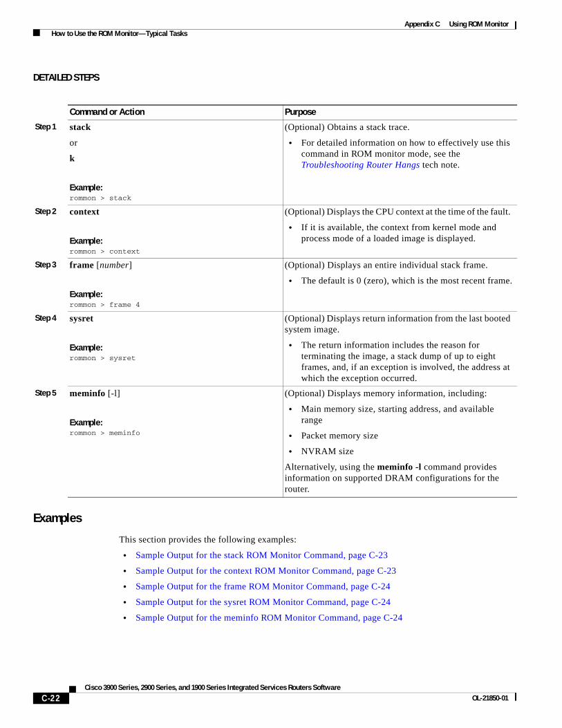
Appendix C Using ROM Monitor How to Use the ROM Monitor—Typical Tasks
DETAILED STEPS
Examples
This section provides the following examples:
• Sample Output for the stack ROM Monitor Command, page C-23
• Sample Output for the context ROM Monitor Command, page C-23
• Sample Output for the frame ROM Monitor Command, page C-24
• Sample Output for the sysret ROM Monitor Command, page C-24
• Sample Output for the meminfo ROM Monitor Command, page C-24
Command or Action Purpose
Step 1 stack
or
k
Example:rommon > stack
(Optional) Obtains a stack trace.
• For detailed information on how to effectively use this command in ROM monitor mode, see the Troubleshooting Router Hangs tech note.
Step 2 context
Example:rommon > context
(Optional) Displays the CPU context at the time of the fault.
• If it is available, the context from kernel mode and process mode of a loaded image is displayed.
Step 3 frame [number]
Example:rommon > frame 4
(Optional) Displays an entire individual stack frame.
• The default is 0 (zero), which is the most recent frame.
Step 4 sysret
Example:rommon > sysret
(Optional) Displays return information from the last booted system image.
• The return information includes the reason for terminating the image, a stack dump of up to eight frames, and, if an exception is involved, the address at which the exception occurred.
Step 5 meminfo [-l]
Example:rommon > meminfo
(Optional) Displays memory information, including:
• Main memory size, starting address, and available range
• Packet memory size
• NVRAM size
Alternatively, using the meminfo -l command provides information on supported DRAM configurations for the router.
C-22Cisco 3900 Series, 2900 Series, and 1900 Series Integrated Services Routers Software
OL-21850-01
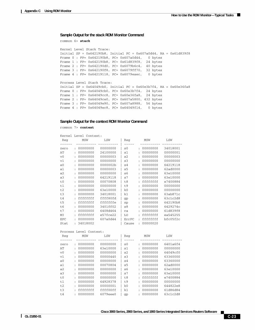
Appendix C Using ROM Monitor How to Use the ROM Monitor—Typical Tasks
Sample Output for the stack ROM Monitor Commandrommon 6> stack
Kernel Level Stack Trace:Initial SP = 0x642190b8, Initial PC = 0x607a0d44, RA = 0x61d839f8Frame 0 : FP= 0x642190b8, PC= 0x607a0d44, 0 bytesFrame 1 : FP= 0x642190b8, PC= 0x61d839f8, 24 bytesFrame 2 : FP= 0x642190d0, PC= 0x6079b6c4, 40 bytesFrame 3 : FP= 0x642190f8, PC= 0x6079ff70, 32 bytesFrame 4 : FP= 0x64219118, PC= 0x6079eaec, 0 bytes
Process Level Stack Trace:Initial SP = 0x64049cb0, Initial PC = 0x60e3b7f4, RA = 0x60e36fa8Frame 0 : FP= 0x64049cb0, PC= 0x60e3b7f4, 24 bytesFrame 1 : FP= 0x64049cc8, PC= 0x60e36fa8, 24 bytesFrame 2 : FP= 0x64049ce0, PC= 0x607a5800, 432 bytesFrame 3 : FP= 0x64049e90, PC= 0x607a8988, 56 bytesFrame 4 : FP= 0x64049ec8, PC= 0x64049f14, 0 bytes
Sample Output for the context ROM Monitor Commandrommon 7> context
Kernel Level Context: Reg MSW LSW | Reg MSW LSW------ ---------- ---------- | ----- ---------- ----------zero : 00000000 00000000 | s0 : 00000000 34018001AT : 00000000 24100000 | s1 : 00000000 00000001v0 : 00000000 00000003 | s2 : 00000000 00000003v1 : 00000000 00000000 | s3 : 00000000 00000000a0 : 00000000 0000002b | s4 : 00000000 64219118a1 : 00000000 00000003 | s5 : 00000000 62ad0000a2 : 00000000 00000000 | s6 : 00000000 63e10000a3 : 00000000 64219118 | s7 : 00000000 63e10000t0 : 00000000 00070808 | t8 : ffffffff e7400884t1 : 00000000 00000000 | t9 : 00000000 00000000t2 : 00000000 63e10000 | k0 : 00000000 00000000t3 : 00000000 34018001 | k1 : 00000000 63ab871ct4 : ffffffff ffff80fd | gp : 00000000 63c1c2d8t5 : ffffffff fffffffe | sp : 00000000 642190b8t6 : 00000000 3401ff02 | s8 : 00000000 6429274ct7 : 00000000 6408d464 | ra : 00000000 61d839f8HI : ffffffff e57fce22 | LO : ffffffff ea545255EPC : 00000000 607a0d44 | ErrPC : ffffffff bfc05f2cStat : 34018002 | Cause : 00000020
Process Level Context: Reg MSW LSW | Reg MSW LSW------ ---------- ---------- | ----- ---------- ----------zero : 00000000 00000000 | s0 : 00000000 6401a6f4AT : 00000000 63e10000 | s1 : 00000000 00000000v0 : 00000000 00000000 | s2 : 00000000 64049cf0v1 : 00000000 00000440 | s3 : 00000000 63360000a0 : 00000000 00000000 | s4 : 00000000 63360000a1 : 00000000 00070804 | s5 : 00000000 62ad0000a2 : 00000000 00000000 | s6 : 00000000 63e10000a3 : 00000000 00000000 | s7 : 00000000 63e10000t0 : 00000000 00000000 | t8 : ffffffff e7400884t1 : 00000000 64928378 | t9 : 00000000 00000000t2 : 00000000 00000001 | k0 : 00000000 644822e8t3 : ffffffff ffff00ff | k1 : 00000000 61d86d84t4 : 00000000 6079eee0 | gp : 00000000 63c1c2d8
C-23Cisco 3900 Series, 2900 Series, and 1900 Series Integrated Services Routers Software
OL-21850-01

Appendix C Using ROM Monitor How to Use the ROM Monitor—Typical Tasks
t5 : 00000000 00000001 | sp : 00000000 64049cb0t6 : 00000000 00000000 | s8 : 00000000 6429274ct7 : 00000000 6408d464 | ra : 00000000 60e36fa8HI : ffffffff e57fce22 | LO : ffffffff ea545255EPC : 00000000 60e3b7f4 | ErrPC : ffffffff ffffffffStat : 3401ff03 | Cause : ffffffff
Sample Output for the frame ROM Monitor Commandrommon 6 > frame 2
Stack Frame 2, SP = 0x642190d0, Size = 40 bytes[0x642190d0 : sp + 0x000] = 0xffffffff[0x642190d4 : sp + 0x004] = 0xbfc05f2c[0x642190d8 : sp + 0x008] = 0xffffffff[0x642190dc : sp + 0x00c] = 0xffffffff[0x642190e0 : sp + 0x010] = 0x6401a6f4[0x642190e4 : sp + 0x014] = 0x00000000[0x642190e8 : sp + 0x018] = 0x64049cf0[0x642190ec : sp + 0x01c] = 0x63360000[0x642190f0 : sp + 0x020] = 0x63360000[0x642190f4 : sp + 0x024] = 0x6079ff70
Sample Output for the sysret ROM Monitor Commandrommon 8> sysret
System Return Info:count: 19, reason: user breakpc:0x801111b0, error address: 0x801111b0Stack Trace:FP: 0x80005ea8, PC: 0x801111b0FP: 0x80005eb4, PC: 0x80113694FP: 0x80005f74, PC: 0x8010eb44FP: 0x80005f9c, PC: 0x80008118FP: 0x80005fac, PC: 0x80008064FP: 0x80005fc4, PC: 0xfff03d70FP: 0x80005ffc, PC: 0x00000000FP: 0x00000000, PC: 0x00000000
Sample Output for the meminfo ROM Monitor Commandrommon 3> meminfo
-------------------------------------------------Current Memory configuration is:Onboard SDRAM: Size = 128 MB : Start Addr = 0x10000000-----Bank 0 128 MB-----Bank 1 0 MBDimm 0: Size = 256 MB : Start Addr = 0x00000000-----Bank 0 128 MB-----Bank 1 128 MB-------------------------------------------------Main memory size: 384 MB in 64 bit mode.Available main memory starts at 0xa0015000, size 393132KBIO (packet) memory size: 10 percent of main memory.NVRAM size: 191KB
You can also use the meminfo -l command to show the supported DRAM configurations for the router. The following is sample output for the command:
C-24Cisco 3900 Series, 2900 Series, and 1900 Series Integrated Services Routers Software
OL-21850-01
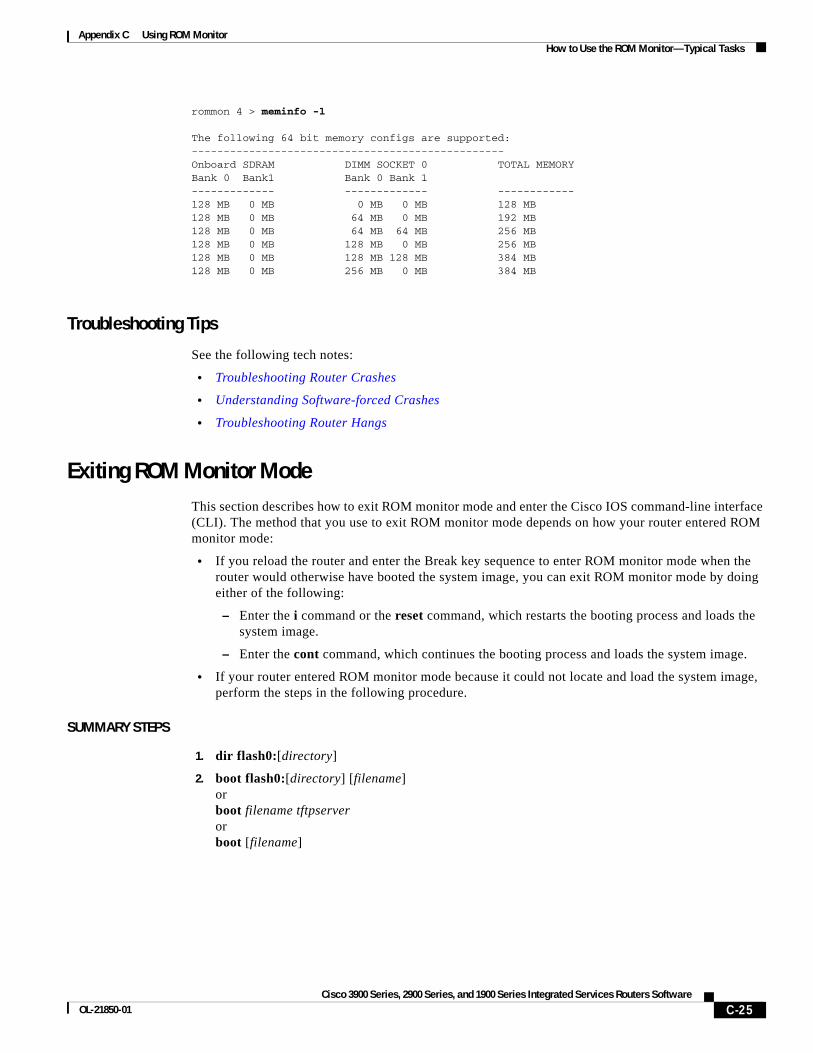
Appendix C Using ROM Monitor How to Use the ROM Monitor—Typical Tasks
rommon 4 > meminfo -l
The following 64 bit memory configs are supported:-------------------------------------------------Onboard SDRAM DIMM SOCKET 0 TOTAL MEMORYBank 0 Bank1 Bank 0 Bank 1------------- ------------- ------------128 MB 0 MB 0 MB 0 MB 128 MB128 MB 0 MB 64 MB 0 MB 192 MB128 MB 0 MB 64 MB 64 MB 256 MB128 MB 0 MB 128 MB 0 MB 256 MB128 MB 0 MB 128 MB 128 MB 384 MB128 MB 0 MB 256 MB 0 MB 384 MB
Troubleshooting Tips
See the following tech notes:
• Troubleshooting Router Crashes
• Understanding Software-forced Crashes
• Troubleshooting Router Hangs
Exiting ROM Monitor ModeThis section describes how to exit ROM monitor mode and enter the Cisco IOS command-line interface (CLI). The method that you use to exit ROM monitor mode depends on how your router entered ROM monitor mode:
• If you reload the router and enter the Break key sequence to enter ROM monitor mode when the router would otherwise have booted the system image, you can exit ROM monitor mode by doing either of the following:
– Enter the i command or the reset command, which restarts the booting process and loads the system image.
– Enter the cont command, which continues the booting process and loads the system image.
• If your router entered ROM monitor mode because it could not locate and load the system image, perform the steps in the following procedure.
SUMMARY STEPS
1. dir flash0:[directory]
2. boot flash0:[directory] [filename] or boot filename tftpserver or boot [filename]
C-25Cisco 3900 Series, 2900 Series, and 1900 Series Integrated Services Routers Software
OL-21850-01

Appendix C Using ROM Monitor How to Use the ROM Monitor—Typical Tasks
DETAILED STEPS
Examples
Sample Output for the dir flash: Command in ROM Monitor moderommon > dir flash0:
File size Checksum File name 2229799 bytes (0x220627) 0x469e c2801-j-m2.113-4T
What to Do Next
If you want to configure the router to load a specified image at the next system reload or power-cycle, see the “Loading and Managing System Images” section in Cisco IOS Configuration Fundamentals Command Reference.
Command or Action Purpose
Step 1 dir flash0:[directory]
Example:rommon > dir flash0:
Displays a list of the files and directories in flash memory.
• Locate the system image that you want the router to load.
• If the system image is not in flash memory, use the second or third option in Step 2.
Step 2 boot flash0:[directory] [filename]
or
boot filename tftpserver
or
boot [filename]
Example:ROMMON > boot flash0:myimage
Example:ROMMON > boot someimage 172.16.30.40
Example:ROMMON > boot
In order, the examples here direct the router to:
• Boot the first image or a specified image in flash memory.
• Boot the specified image over the network from the specified TFTP server (hostname or IP address).
• Boot from the boothelper image because it does not recognize the device ID. This form of the command is used to netboot a specified image.
You can override the default boothelper image setting by setting the BOOTLDR Monitor environment variable to point to another image. Any system image can be used for this purpose.
Note Options to the boot command are -x (load image but do not execute) and -v (verbose).
C-26Cisco 3900 Series, 2900 Series, and 1900 Series Integrated Services Routers Software
OL-21850-01

Appendix C Using ROM Monitor Additional References
Additional ReferencesThe following sections provide references related to using the ROM monitor.
Related Documents
Technical Assistance
Related Topic Document Title
Connecting your PC to the router console port Hardware installation guide for your router
Break key sequence combinations for entering ROM monitor mode within the first 60 seconds of rebooting the router
Standard Break Key Sequence Combinations During Password Recovery
Upgrading the ROM monitor ROM Monitor Download Procedures for Cisco 2691, Cisco, 3631, Cisco 3725, and Cisco 3745 Routers
Using the boot image (Rx-boot) to recover or upgrade the system image
How to Upgrade from ROMmon Using the Boot Image
Booting and configuration register commands Cisco IOS Configuration Fundamentals Command Reference
Loading and maintaining system images; rebooting Cisco IOS Configuration Fundamentals Configuration Guide
Choosing and downloading system images Software Center at
http://www.cisco.com/kobayashi/sw-center/index.shtml
Router crashes Troubleshooting Router Crashes
Understanding Software-forced Crashes
Router hangs Troubleshooting Router Hangs
Description Link
Technical Assistance Center (TAC) home page, containing 30,000 pages of searchable technical content, including links to products, technologies, solutions, technical tips, and tools. Registered Cisco.com users can log in from this page to access even more content.1
1. You must have an account at Cisco.com. If you do not have an account or have forgotten your username or password, click Cancel at the login dialog box and follow the instructions that appear.
http://www.cisco.com/public/support/tac/home.shtml
C-27Cisco 3900 Series, 2900 Series, and 1900 Series Integrated Services Routers Software
OL-21850-01

Appendix C Using ROM Monitor Additional References
CCDE, CCENT, CCSI, Cisco Eos, Cisco HealthPresence, Cisco IronPort, the Cisco logo, Cisco Nurse Connect, Cisco Pulse, Cisco SensorBase, Cisco StackPower, Cisco StadiumVision, Cisco TelePresence, Cisco Unified Computing System, Cisco WebEx, DCE, Flip Channels, Flip for Good, Flip Mino, Flipshare (Design), Flip Ultra, Flip Video, Flip Video (Design), Instant Broadband, and Welcome to the Human Network are trademarks; Changing the Way We Work, Live, Play, and Learn, Cisco Capital, Cisco Capital (Design), Cisco:Financed (Stylized), Cisco Store, Flip Gift Card, and One Million Acts of Green are service marks; and Access Registrar, Aironet, AllTouch, AsyncOS, Bringing the Meeting To You, Catalyst, CCDA, CCDP, CCIE, CCIP, CCNA, CCNP, CCSP, CCVP, Cisco, the Cisco Certified Internetwork Expert logo, Cisco IOS, Cisco Lumin, Cisco Nexus, Cisco Press, Cisco Systems, Cisco Systems Capital, the Cisco Systems logo, Cisco Unity, Collaboration Without Limitation, Continuum, EtherFast, EtherSwitch, Event Center, Explorer, Follow Me Browsing, GainMaker, iLYNX, IOS, iPhone, IronPort, the IronPort logo, Laser Link, LightStream, Linksys, MeetingPlace, MeetingPlace Chime Sound, MGX, Networkers, Networking Academy, PCNow, PIX, PowerKEY, PowerPanels, PowerTV, PowerTV (Design), PowerVu, Prisma, ProConnect, ROSA, SenderBase, SMARTnet, Spectrum Expert, StackWise, WebEx, and the WebEx logo are registered trademarks of Cisco Systems, Inc. and/or its affiliates in the United States and certain other countries.
All other trademarks mentioned in this document or website are the property of their respective owners. The use of the word partner does not imply a partnership relationship between Cisco and any other company. (0910R)
Any Internet Protocol (IP) addresses used in this document are not intended to be actual addresses. Any examples, command display output, and figures included in the document are shown for illustrative purposes only. Any use of actual IP addresses in illustrative content is unintentional and coincidental. © 2009-2010 Cisco Systems, Inc. All rights reserved.
C-28Cisco 3900 Series, 2900 Series, and 1900 Series Integrated Services Routers Software
OL-21850-01
Cisco 3900 Series, 2900 Series, and 1900 OL-21850-01
A
P P E N D I X D Changing the Configuration Register SettingsThe following sections describe the 16-bit configuration register in NVRAM in the Cisco 3900 series, 2900 series, and 1900 series integrated services routers (ISRs):
• About the Configuration Register, page D-1
• Changing the Configuration Register Settings, page D-4
• Displaying the Configuration Register Settings, page D-5
• Configuring the Console Line Speed (Cisco IOS CLI), page D-5
About the Configuration RegisterThe router has a 16-bit configuration register in NVRAM. Each bit has value 1 (on or set) or value 0 (off or clear), and each bit setting affects the router behavior upon the next reload power cycle.
You can use the configuration register to
• Force the router to boot into the ROM monitor (bootstrap program)
• Select a boot source and default boot filename
• Enable or disable the Break function
• Control broadcast addresses
• Recover a lost password
• Change the console line speed
Table 1 describes the configuration register bits.
Table 1 Configuration Register Bit Descriptions
Bit Number Hexadecimal Meaning
00–03 0x0000–0x000F
Boot field. The boot field setting determines whether the router loads an operating system and where it obtains the system image.
See Table 2 for details.
06 0x0040 Causes the system software to ignore the contents of NVRAM.
07 0x0080 OEM1 bit enabled.
D-1Series Integrated Services Routers Software
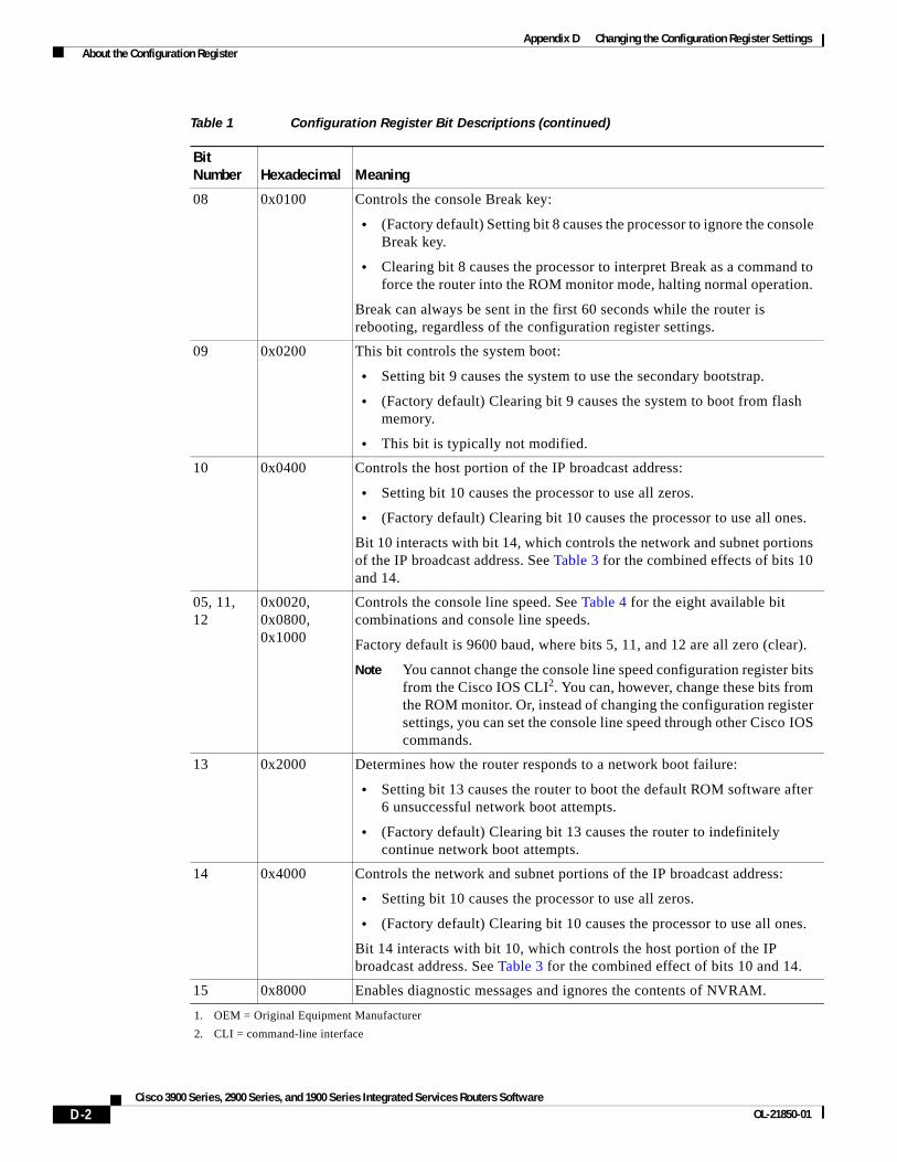
Appendix D Changing the Configuration Register Settings About the Configuration Register
08 0x0100 Controls the console Break key:
• (Factory default) Setting bit 8 causes the processor to ignore the console Break key.
• Clearing bit 8 causes the processor to interpret Break as a command to force the router into the ROM monitor mode, halting normal operation.
Break can always be sent in the first 60 seconds while the router is rebooting, regardless of the configuration register settings.
09 0x0200 This bit controls the system boot:
• Setting bit 9 causes the system to use the secondary bootstrap.
• (Factory default) Clearing bit 9 causes the system to boot from flash memory.
• This bit is typically not modified.
10 0x0400 Controls the host portion of the IP broadcast address:
• Setting bit 10 causes the processor to use all zeros.
• (Factory default) Clearing bit 10 causes the processor to use all ones.
Bit 10 interacts with bit 14, which controls the network and subnet portions of the IP broadcast address. See Table 3 for the combined effects of bits 10 and 14.
05, 11, 12
0x0020, 0x0800, 0x1000
Controls the console line speed. See Table 4 for the eight available bit combinations and console line speeds.
Factory default is 9600 baud, where bits 5, 11, and 12 are all zero (clear).
Note You cannot change the console line speed configuration register bits from the Cisco IOS CLI2. You can, however, change these bits from the ROM monitor. Or, instead of changing the configuration register settings, you can set the console line speed through other Cisco IOS commands.
13 0x2000 Determines how the router responds to a network boot failure:
• Setting bit 13 causes the router to boot the default ROM software after 6 unsuccessful network boot attempts.
• (Factory default) Clearing bit 13 causes the router to indefinitely continue network boot attempts.
14 0x4000 Controls the network and subnet portions of the IP broadcast address:
• Setting bit 10 causes the processor to use all zeros.
• (Factory default) Clearing bit 10 causes the processor to use all ones.
Bit 14 interacts with bit 10, which controls the host portion of the IP broadcast address. See Table 3 for the combined effect of bits 10 and 14.
15 0x8000 Enables diagnostic messages and ignores the contents of NVRAM.
1. OEM = Original Equipment Manufacturer
2. CLI = command-line interface
Table 1 Configuration Register Bit Descriptions (continued)
Bit Number Hexadecimal Meaning
D-2Cisco 3900 Series, 2900 Series, and 1900 Series Integrated Services Routers Software
OL-21850-01
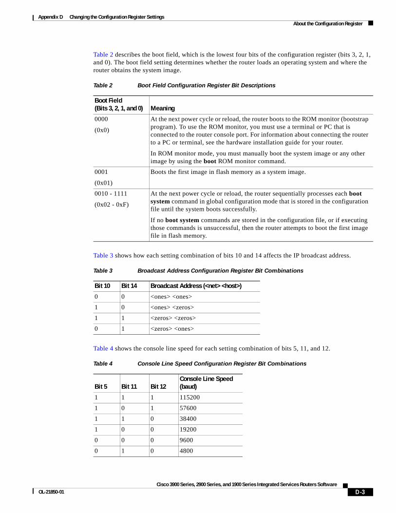
Appendix D Changing the Configuration Register Settings About the Configuration Register
Table 2 describes the boot field, which is the lowest four bits of the configuration register (bits 3, 2, 1, and 0). The boot field setting determines whether the router loads an operating system and where the router obtains the system image.
Table 3 shows how each setting combination of bits 10 and 14 affects the IP broadcast address.
Table 4 shows the console line speed for each setting combination of bits 5, 11, and 12.
Table 2 Boot Field Configuration Register Bit Descriptions
Boot Field (Bits 3, 2, 1, and 0) Meaning
0000
(0x0)
At the next power cycle or reload, the router boots to the ROM monitor (bootstrap program). To use the ROM monitor, you must use a terminal or PC that is connected to the router console port. For information about connecting the router to a PC or terminal, see the hardware installation guide for your router.
In ROM monitor mode, you must manually boot the system image or any other image by using the boot ROM monitor command.
0001
(0x01)
Boots the first image in flash memory as a system image.
0010 - 1111
(0x02 - 0xF)
At the next power cycle or reload, the router sequentially processes each boot system command in global configuration mode that is stored in the configuration file until the system boots successfully.
If no boot system commands are stored in the configuration file, or if executing those commands is unsuccessful, then the router attempts to boot the first image file in flash memory.
Table 3 Broadcast Address Configuration Register Bit Combinations
Bit 10 Bit 14 Broadcast Address (<net> <host>)
0 0 <ones> <ones>
1 0 <ones> <zeros>
1 1 <zeros> <zeros>
0 1 <zeros> <ones>
Table 4 Console Line Speed Configuration Register Bit Combinations
Bit 5 Bit 11 Bit 12Console Line Speed (baud)
1 1 1 115200
1 0 1 57600
1 1 0 38400
1 0 0 19200
0 0 0 9600
0 1 0 4800
D-3Cisco 3900 Series, 2900 Series, and 1900 Series Integrated Services Routers Software
OL-21850-01

Appendix D Changing the Configuration Register Settings Changing the Configuration Register Settings
Changing the Configuration Register SettingsYou can change the configuration register settings from either the ROM monitor or the Cisco IOS CLI. This section describes how to modify the configuration register settings from the Cisco IOS CLI.
To change the configuration register using the ROM monitor, see Appendix C, “Using ROM Monitor,” in this guide.
To change the configuration register settings from the Cisco IOS CLI, complete the following steps:
Step 1 Connect a terminal or PC to the router console port. If you need help, see the hardware installation guide for your router.
Step 2 Configure your terminal or terminal emulation software for 9600 baud (default), 8 data bits, no parity, and 2 stop bits.
Step 3 Power on the router.
Step 4 If you are asked whether you would like to enter the initial dialog, answer no:
Would you like to enter the initial dialog? [yes]: no
After a few seconds, the user EXEC prompt (Router>) appears.
Step 5 Enter privileged EXEC mode by typing enable and, if prompted, enter your password:
Router> enablePassword: passwordRouter#
Step 6 Enter global configuration mode:
Router# configure terminal
Enter configuration commands, one per line.Edit with DELETE, CTRL/W, and CTRL/U; end with CTRL/Z
Step 7 To change the configuration register settings, enter the config-register value command, where value is a hexadecimal number preceded by 0x:
Router(config)# config-register 0xvalue
Note The Cisco IOS software does not allow you to change the console speed bits directly with the config-register command. To change the console speed from the Cisco IOS CLI, see the “Configuring the Console Line Speed (Cisco IOS CLI)” section on page D-5.
Step 8 Exit global configuration mode:
Router(config)# endRouter#
0 1 1 2400
0 0 1 1200
Table 4 Console Line Speed Configuration Register Bit Combinations (continued)
Bit 5 Bit 11 Bit 12Console Line Speed (baud)
D-4Cisco 3900 Series, 2900 Series, and 1900 Series Integrated Services Routers Software
OL-21850-01
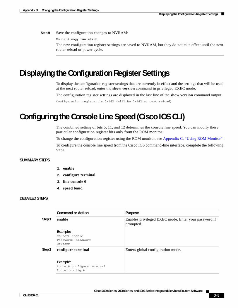
Appendix D Changing the Configuration Register Settings Displaying the Configuration Register Settings
Step 9 Save the configuration changes to NVRAM:
Router# copy run start
The new configuration register settings are saved to NVRAM, but they do not take effect until the next router reload or power cycle.
Displaying the Configuration Register SettingsTo display the configuration register settings that are currently in effect and the settings that will be used at the next router reload, enter the show version command in privileged EXEC mode.
The configuration register settings are displayed in the last line of the show version command output:
Configuration register is 0x142 (will be 0x142 at next reload)
Configuring the Console Line Speed (Cisco IOS CLI)The combined setting of bits 5, 11, and 12 determines the console line speed. You can modify these particular configuration register bits only from the ROM monitor.
To change the configuration register using the ROM monitor, see Appendix C, “Using ROM Monitor”.
To configure the console line speed from the Cisco IOS command-line interface, complete the following steps.
SUMMARY STEPS
1. enable
2. configure terminal
3. line console 0
4. speed baud
DETAILED STEPS
Command or Action Purpose
Step 1 enable
Example:Router> enablePassword: passwordRouter#
Enables privileged EXEC mode. Enter your password if prompted.
Step 2 configure terminal
Example:Router# configure terminalRouter(config)#
Enters global configuration mode.
D-5Cisco 3900 Series, 2900 Series, and 1900 Series Integrated Services Routers Software
OL-21850-01
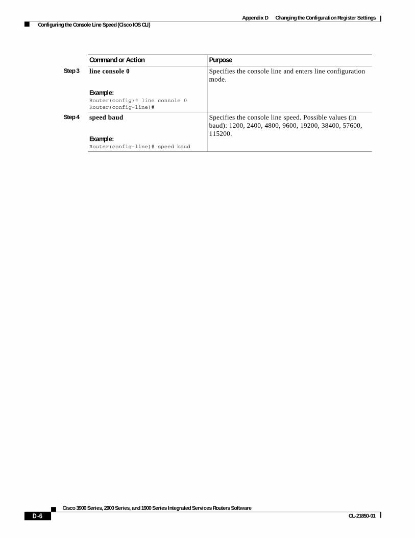
Appendix D Changing the Configuration Register Settings Configuring the Console Line Speed (Cisco IOS CLI)
Step 3 line console 0
Example:Router(config)# line console 0 Router(config-line)#
Specifies the console line and enters line configuration mode.
Step 4 speed baud
Example:Router(config-line)# speed baud
Specifies the console line speed. Possible values (in baud): 1200, 2400, 4800, 9600, 19200, 38400, 57600, 115200.
Command or Action Purpose
D-6Cisco 3900 Series, 2900 Series, and 1900 Series Integrated Services Routers Software
OL-21850-01
Appendix D Changing the Configuration Register Settings Configuring the Console Line Speed (Cisco IOS CLI)
CCDE, CCENT, CCSI, Cisco Eos, Cisco HealthPresence, Cisco IronPort, the Cisco logo, Cisco Nurse Connect, Cisco Pulse, Cisco SensorBase, Cisco StackPower, Cisco StadiumVision, Cisco TelePresence, Cisco Unified Computing System, Cisco WebEx, DCE, Flip Channels, Flip for Good, Flip Mino, Flipshare (Design), Flip Ultra, Flip Video, Flip Video (Design), Instant Broadband, and Welcome to the Human Network are trademarks; Changing the Way We Work, Live, Play, and Learn, Cisco Capital, Cisco Capital (Design), Cisco:Financed (Stylized), Cisco Store, Flip Gift Card, and One Million Acts of Green are service marks; and Access Registrar, Aironet, AllTouch, AsyncOS, Bringing the Meeting To You, Catalyst, CCDA, CCDP, CCIE, CCIP, CCNA, CCNP, CCSP, CCVP, Cisco, the Cisco Certified Internetwork Expert logo, Cisco IOS, Cisco Lumin, Cisco Nexus, Cisco Press, Cisco Systems, Cisco Systems Capital, the Cisco Systems logo, Cisco Unity, Collaboration Without Limitation, Continuum, EtherFast, EtherSwitch, Event Center, Explorer, Follow Me Browsing, GainMaker, iLYNX, IOS, iPhone, IronPort, the IronPort logo, Laser Link, LightStream, Linksys, MeetingPlace, MeetingPlace Chime Sound, MGX, Networkers, Networking Academy, PCNow, PIX, PowerKEY, PowerPanels, PowerTV, PowerTV (Design), PowerVu, Prisma, ProConnect, ROSA, SenderBase, SMARTnet, Spectrum Expert, StackWise, WebEx, and the WebEx logo are registered trademarks of Cisco Systems, Inc. and/or its affiliates in the United States and certain other countries.
All other trademarks mentioned in this document or website are the property of their respective owners. The use of the word partner does not imply a partnership relationship between Cisco and any other company. (0910R)
Any Internet Protocol (IP) addresses used in this document are not intended to be actual addresses. Any examples, command display output, and figures included in the document are shown for illustrative purposes only. Any use of actual IP addresses in illustrative content is unintentional and coincidental. © 2009-2010 Cisco Systems, Inc. All rights reserved.
D-7Cisco 3900 Series, 2900 Series, and 1900 Series Integrated Services Routers Software
OL-21850-01

Appendix D Changing the Configuration Register Settings Configuring the Console Line Speed (Cisco IOS CLI)
D-8Cisco 3900 Series, 2900 Series, and 1900 Series Integrated Services Routers Software
OL-21850-01