soft copy of railway wagon braking system1
TRANSCRIPT
Presented by:-
S. Salim Malik
149Y1A03A9
KSRM COLLEGE OF ENGINEERING
KADAPA
Presentation on
RAILWAY WAGON BRAKING SYSTEM
ABSTRACT:-
In Railway wagon as well as in passenger
cars the braking system plays a very
important role to stop the train, to maintain
the speed of the train within specific limit.
Brakes are the devices on the trains to bring
it to standstill.
A moving train contains energy, known
as kinetic energy, which needs to be
removed from the train in order to cause it to
stop. The simplest way of doing this is to
convert the kinetic energy into heat energy.
The conversion is usually done by applying
a contact material to the rotating wheels or
to discs attached to the axles. The material
creates friction and converts the kinetic
energy into heat energy. The wheels slow
down and eventually the train stops. The
material used for braking is normally in the
form of a block or pad.
The vast majority of the world's trains are
equipped with braking systems which uses
compressed air as the force to push the
blocks on to wheels or pads on to discs.
These systems are known as "Air Brakes" or
"Pneumatic Brakes". The compressed air is
transmitted along the train through a "brake
pipe". Changing the level of air pressure in
the pipe causes a change in the state of the
brake on each vehicle. The system is in
widespread use throughout the world.
An alternative to air brake known as
vacuum brake is also used in railway wagon.
Like the air brake the vacuum brake system
is controlled through a brake pipe
connecting a brake valve in the driver’s cab
with braking equipment on each vehicle.
The operation of the brake equipment on
each vehicle depends on the condition of
vacuum created in the pipe by an ejector or
exhauster.
Another braking system used by electric
train is Electric Dynamic Braking System.
The basic principle of operation is to convert
electric motor into a braking generator
dissipating the kinetic energy as heat energy.
Regenerative braking is similar to Dynamic
Braking. Only difference is that, it transmits
generated electricity to overhead wires
instead of dissipating it as heat, and is
becoming more common due to its ability to
save energy.
To overcome the problems associated
with air braking system, a new braking
system called “Electronically Controlled
Pneumatic Brakes” (E.C.P.) is generally
used in Railway Wagons. Before E.C.P.
Electro Pneumatic Brakes are also in use.
This is all about braking systems used in
railway wagon as well as in passenger cars.
To prevent accidents some Automatic
Systems like Automatic Warning Systems
are used. They vary the speed or stop the
train according to the signal aspects.
INTRODUCTION:- The brakes are used on the coaches of
railway trains to enable deceleration, control
acceleration (downhill) or to keep them
standing when parked. While the basic
principle is similar from road vehicle, the
usage and operational features are more
complex because of the need to control
multiple linked carriages and to be effective
on vehicles left without a prime mover. In
the control of any braking system the
important factors that govern braking action
in any vehicle are pressure, surface area in
contact, amount of heat generation and
braking material used. Keeping in view the
safety of human life and physical resources
the basic requirements of brake are:
The brake must be strong enough to stop
the vehicle during an emergency with in
shortest possible distance.
There should be no skidding during brake
application and driver must have proper
control over the vehicle during emergency.
Effectiveness of brakes should remain
constant even on prolonged application or
during descending on a down gradient
Brake must keep the vehicle in a stationary
position
even when the driver is not present. The
brake used in railway vehicles can be
classified according to the method of their
activation into following categories.
Pneumatic Brake
Electrodynamic Brake
Mechanical Brake
Electromagnetic Brake
Pneumatic Brake may be further classified
into two types
Vacuum Brake
Compressed air brake
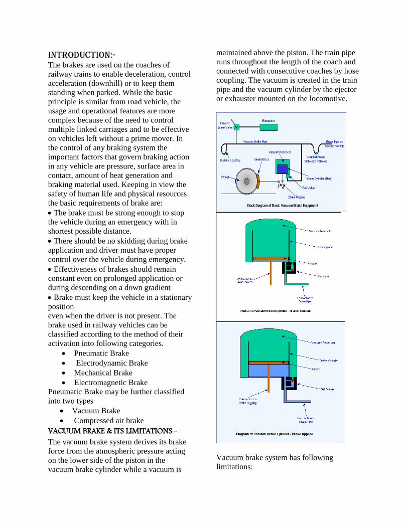
VACUUM BRAKE & ITS LIMITATIONS:- The vacuum brake system derives its brake
force from the atmospheric pressure acting
on the lower side of the piston in the
vacuum brake cylinder while a vacuum is
maintained above the piston. The train pipe
runs throughout the length of the coach and
connected with consecutive coaches by hose
coupling. The vacuum is created in the train
pipe and the vacuum cylinder by the ejector
or exhauster mounted on the locomotive.
Vacuum brake system has following
limitations:
Brake cylinder piston takes longer
time to release after each application
of brakes because of single train
pipe. On a very long train, a
considerable volume of air has to be
admitted to the train pipe to make a
full brake application, and a
considerable volume has to be
exhausted to release the brake.
Vacuum brakes are not suitable for
high speed trains the maximum
pressure available for brake
application is only atmospheric. The
brake power is inadequate for higher
loads and speed.
The practical limit on the degree of
vacuum attainable means that a very
large brake piston and cylinder are
required to generate the force
necessary on the brake blocks. The
existence of vacuum in the train pipe
can cause debris to be sucked in.
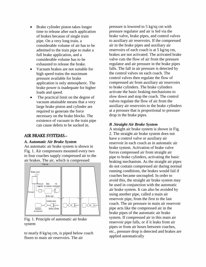
AIR BRAKE SYSTEMS:- A. Automatic Air Brake System An automatic air brake system is shown in
Fig. 1. Air compressors mounted every two
to four coaches supply compressed air to the
air brakes. The air, which is compressed
Fig. 1. Principle of automatic air brake
system
to nearly 8 kg/sq cm, is piped below coach
floors to main air reservoirs. The air
pressure is lowered to 5 kg/sq cm with
pressure regulator and air is fed via the
brake valve, brake pipes, and control valves
to auxiliary air reservoirs. If the compressed
air in the brake pipes and auxiliary air
reservoirs of each coach is at 5 kg/sq cm,
brakes are not activated. The activated brake
valve cuts the flow of air from the pressure
regulator and air pressure in the brake pipes
falls. The fall in air pressure is detected by
the control valves on each coach. The
control valves then regulate the flow of
compressed air from auxiliary air reservoirs
to brake cylinders. The brake cylinders
activate the basic braking mechanisms to
slow down and stop the coach. The control
valves regulate the flow of air from the
auxiliary air reservoirs to the brake cylinders
at a pressure that is proportional to pressure
drop in the brake pipes.
B .Straight Air Brake System
A straight air brake system is shown in Fig.
2. The straight air brake system does not
have a control valve or auxiliary air
reservoir in each coach as in automatic air
brake system. Activation of brake valve
forces compressed air from straight air
pipe to brake cylinders, activating the basic
braking mechanism. As the straight air pipes
do not contain compressed air during normal
running conditions, the brakes would fail if
coaches became uncoupled. In order to
avoid this, the straight air brake system may
be used in conjunction with the automatic
air brake system. It can also be avoided by
using another pipe, called a main air
reservoir pipe, from the first to the last
coach. The air pressure in main air reservoir
pipe acts like the compressed air in the
brake pipes of the automatic air brake
system. If compressed air in this main air
reservoir pipe falls, or if it leaks from air
pipes or from air hoses between coaches,
etc., pressure drop is detected and brakes are
applied automatically
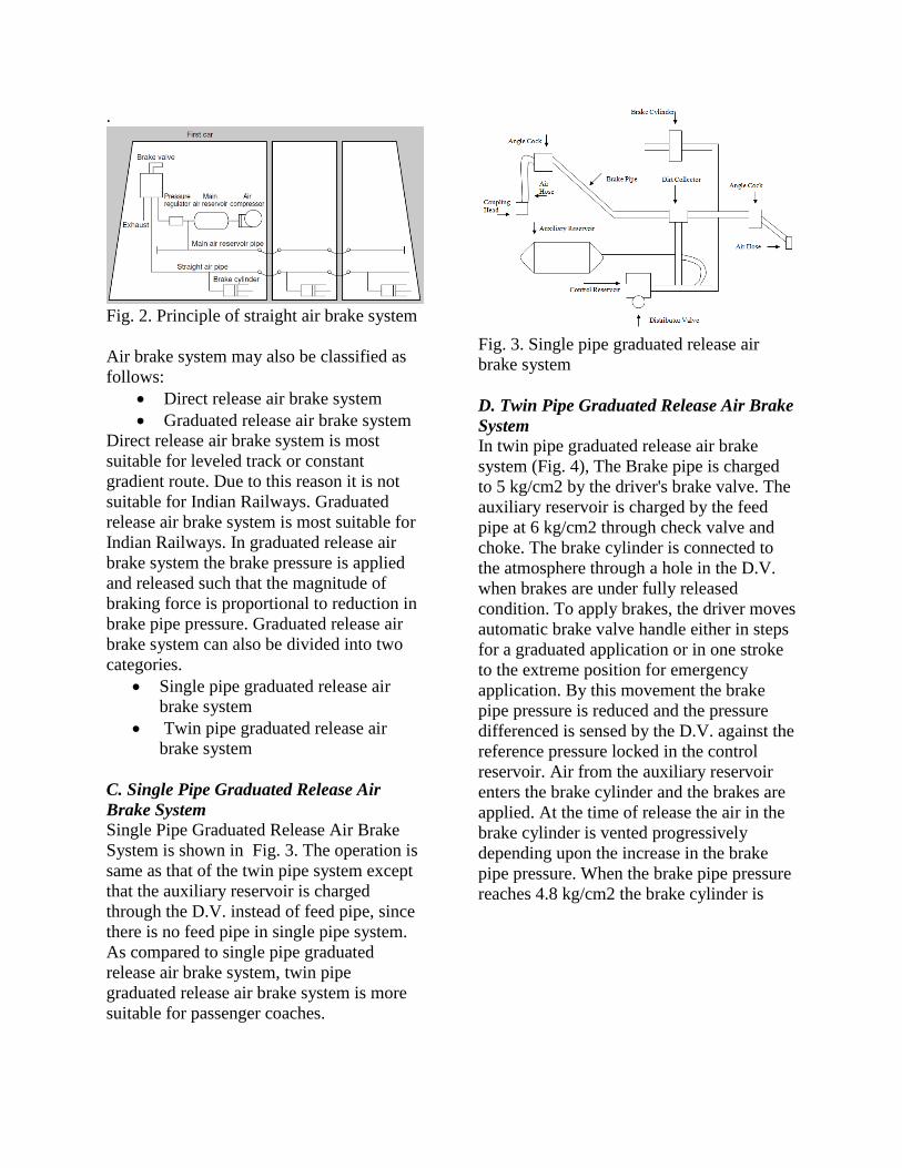
.
Fig. 2. Principle of straight air brake system
Air brake system may also be classified as
follows:
Direct release air brake system
Graduated release air brake system
Direct release air brake system is most
suitable for leveled track or constant
gradient route. Due to this reason it is not
suitable for Indian Railways. Graduated
release air brake system is most suitable for
Indian Railways. In graduated release air
brake system the brake pressure is applied
and released such that the magnitude of
braking force is proportional to reduction in
brake pipe pressure. Graduated release air
brake system can also be divided into two
categories.
Single pipe graduated release air
brake system
Twin pipe graduated release air
brake system
C. Single Pipe Graduated Release Air
Brake System
Single Pipe Graduated Release Air Brake
System is shown in Fig. 3. The operation is
same as that of the twin pipe system except
that the auxiliary reservoir is charged
through the D.V. instead of feed pipe, since
there is no feed pipe in single pipe system.
As compared to single pipe graduated
release air brake system, twin pipe
graduated release air brake system is more
suitable for passenger coaches.
Fig. 3. Single pipe graduated release air
brake system
D. Twin Pipe Graduated Release Air Brake
System
In twin pipe graduated release air brake
system (Fig. 4), The Brake pipe is charged
to 5 kg/cm2 by the driver's brake valve. The
auxiliary reservoir is charged by the feed
pipe at 6 kg/cm2 through check valve and
choke. The brake cylinder is connected to
the atmosphere through a hole in the D.V.
when brakes are under fully released
condition. To apply brakes, the driver moves
automatic brake valve handle either in steps
for a graduated application or in one stroke
to the extreme position for emergency
application. By this movement the brake
pipe pressure is reduced and the pressure
differenced is sensed by the D.V. against the
reference pressure locked in the control
reservoir. Air from the auxiliary reservoir
enters the brake cylinder and the brakes are
applied. At the time of release the air in the
brake cylinder is vented progressively
depending upon the increase in the brake
pipe pressure. When the brake pipe pressure
reaches 4.8 kg/cm2 the brake cylinder is
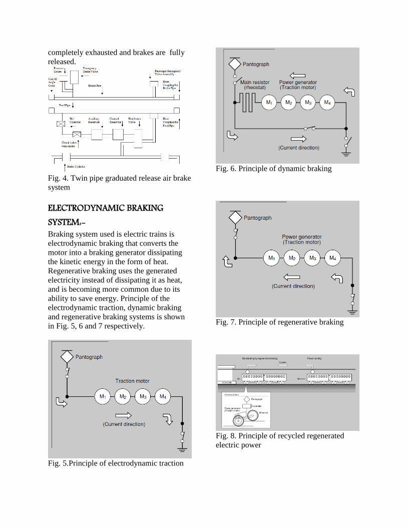
completely exhausted and brakes are fully
released.
Fig. 4. Twin pipe graduated release air brake
system
ELECTRODYNAMIC BRAKING SYSTEM:- Braking system used is electric trains is
electrodynamic braking that converts the
motor into a braking generator dissipating
the kinetic energy in the form of heat.
Regenerative braking uses the generated
electricity instead of dissipating it as heat,
and is becoming more common due to its
ability to save energy. Principle of the
electrodynamic traction, dynamic braking
and regenerative braking systems is shown
in Fig. 5, 6 and 7 respectively.
Fig. 5.Principle of electrodynamic traction
Fig. 6. Principle of dynamic braking
Fig. 7. Principle of regenerative braking
Fig. 8. Principle of recycled regenerated
electric power
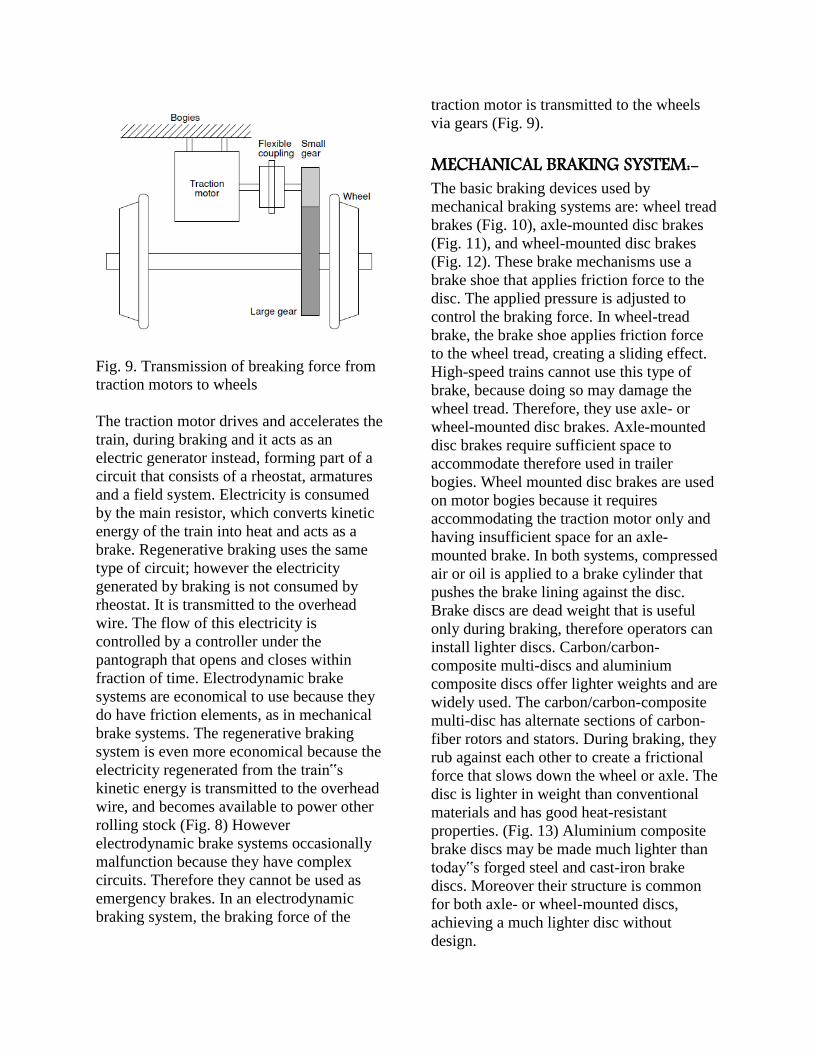
Fig. 9. Transmission of breaking force from
traction motors to wheels
The traction motor drives and accelerates the
train, during braking and it acts as an
electric generator instead, forming part of a
circuit that consists of a rheostat, armatures
and a field system. Electricity is consumed
by the main resistor, which converts kinetic
energy of the train into heat and acts as a
brake. Regenerative braking uses the same
type of circuit; however the electricity
generated by braking is not consumed by
rheostat. It is transmitted to the overhead
wire. The flow of this electricity is
controlled by a controller under the
pantograph that opens and closes within
fraction of time. Electrodynamic brake
systems are economical to use because they
do have friction elements, as in mechanical
brake systems. The regenerative braking
system is even more economical because the
electricity regenerated from the train‟s
kinetic energy is transmitted to the overhead
wire, and becomes available to power other
rolling stock (Fig. 8) However
electrodynamic brake systems occasionally
malfunction because they have complex
circuits. Therefore they cannot be used as
emergency brakes. In an electrodynamic
braking system, the braking force of the
traction motor is transmitted to the wheels
via gears (Fig. 9).
MECHANICAL BRAKING SYSTEM:- The basic braking devices used by
mechanical braking systems are: wheel tread
brakes (Fig. 10), axle-mounted disc brakes
(Fig. 11), and wheel-mounted disc brakes
(Fig. 12). These brake mechanisms use a
brake shoe that applies friction force to the
disc. The applied pressure is adjusted to
control the braking force. In wheel-tread
brake, the brake shoe applies friction force
to the wheel tread, creating a sliding effect.
High-speed trains cannot use this type of
brake, because doing so may damage the
wheel tread. Therefore, they use axle- or
wheel-mounted disc brakes. Axle-mounted
disc brakes require sufficient space to
accommodate therefore used in trailer
bogies. Wheel mounted disc brakes are used
on motor bogies because it requires
accommodating the traction motor only and
having insufficient space for an axle-
mounted brake. In both systems, compressed
air or oil is applied to a brake cylinder that
pushes the brake lining against the disc.
Brake discs are dead weight that is useful
only during braking, therefore operators can
install lighter discs. Carbon/carbon-
composite multi-discs and aluminium
composite discs offer lighter weights and are
widely used. The carbon/carbon-composite
multi-disc has alternate sections of carbon-
fiber rotors and stators. During braking, they
rub against each other to create a frictional
force that slows down the wheel or axle. The
disc is lighter in weight than conventional
materials and has good heat-resistant
properties. (Fig. 13) Aluminium composite
brake discs may be made much lighter than
today‟s forged steel and cast-iron brake
discs. Moreover their structure is common
for both axle- or wheel-mounted discs,
achieving a much lighter disc without
design.
Fig. 10. Principle of wheel tread brakes
Fig. 11. Principle of axle-mounted disc
brakes
Fig. 12. Principle of wheel-mounted disc
brakes
Fig. 13. Carbon/Carbon-composite multi-
disc system.
ELECTROMAGNETIC BRAKING SYSTEM:- Conventional train braking systems depend
heavily on adhesion between the wheel tread
and the rail. In the case high-speed trains,
adhesion decreases as speeds increase,
making it necessary for the train to reduce
braking force to avoid wheel sliding. This
result is longer braking distances. To
overcome this problem, a electromagnetic
brake system that does not depend on
adhesion was developed. It produce a
braking force by using magnetic repulsion
obtained from eddy currents generated on
the top surface of the rails. Earlier it was not
used because of assumption that the eddy
currents would heat small sections of the rail
to such a degree that the rail would bend
sideways. This is solved by development of
a electromagnetic brake that uses eddy
currents and frictional force. Fig. 14 shows
the principle of electromagnetic brake. The
electromagnetic brake on bogie is connected
to batteries that create alternating north and
south poles forming magnetic fields between
the poles. The magnetic fields generate eddy
currents in the top surface of the rails,
creating a force acting in an opposite
direction to the movement of the train, in
other words, a braking force. An on field
view of electromagnetic brake is shown in
Fig. 15.

Fig. 14. Principle of electromagnetic brake
Fig. 15. An on field view of electromagnetic
brake
Advantages of Air brake over Vacuum brakes – More efficient and powerful braking.
Reduced braking distances - Uniform
braking effort over the length of the
train ( in vacuum brake trains there is a
15to 20% reduction in brake power
along the train length).
Brake power maintained over long runs
there by enabling end to end running (
Vacuum brake trains experience a 10 to
15% deterioration in brake power
within 500 kms. of run.)
Requires less time for examination
thereby reducing Pre-departure
detention of trains for brake power
certification Vacuum brake trains -
takes 2 hours. Air Brake trains - takes 1
hours.
Lighter weight of brake equipments thereby enabling higher pay loads
for vacuum brakes - 685 kgs. per
wagon. for Air brakes - 275 kgs. per
wagon.
Advantages in Mechanical Brakes:- Equal braking action on all wheels. Increased braking force. Simple in construction. Low wear rate of brake linings. Flexibility of brake linings. Increased mechanical advantage. Advantages in Electromagnetic Brakes:- No friction
Low maintenance requirement
Less noise
Simple in design
High degree of safety
Conclusion:-
Vacuum brakes have extremely limited
applications because of longer longer to
function and unsuitable for high speed
trains.
Air brakes are efficient as compared to
vacuum brakes; however they require
considerable stopping distance therefore
cannot be used for emergency braking.
Mechanical brakes should be kept in
reserve in parallel with another breaking
technique and should be used to completely
stop the engine at low speed.
The required braking forces can be
obtained in a wide range, with regeneration
braking used in a high speed range and
rheostat braking in low speed range.
Electrodynamic brake systems
occasionally malfunction because they have

complex circuits. Therefore they cannot be
used as emergency brakes.
Electromagnetic braking in high-speed
train is efficient method of breaking.
Reference:- International journal of engineering
research and Technology