snia emerald™ power efficiency measurement … emerald power efficiency measurement specification...
TRANSCRIPT

SNIA Emerald™ Power Efficiency Measurement Specification
Version 2.0.2
This document has been released and approved by the SNIA. The SNIA believes that the ideas, methodologies and technologies described in this document accurately represent the SNIA goals and are appropriate for widespread distribution. Suggestions for revision should be directed to http://www.snia.org/feedback/.
SNIA Technical Position
12 August, 2013

SNIA Emerald™ Power Efficiency Measurement Specification
ii SNIA Emerald™ Power Efficiency Measurement Specification V2.0.2 SNIA Technical Position
Revision History
Revision Release Date Changes
0.0.1 9 April 2008 Initial Document Outline
0.2.10 19 August 2010 Public Review Draft
0.3.20 24 May 2011 SNIA Ballot Draft
0.3.22 7 June 2011 SNIA Ballot Draft
1.0 23 August 2011 Editorial work to format SNIA Technical Position
2.0.0
11 September 2012 Added Hot band workload definition, pre-fill, and adjusted test order for Online and Near-online. Add definition of auto tiering.
2.0.0 21 September, 2012 Editorial pass with changes to formatting, headings (division into more subsections), spelling, grammar, usage, check.
2.00 Rev. 1 4 October, 2012 Formatted as a Working Draft for membership ballot.
2.00 Rev. 1 12 December, 2012 Approved by membership, formatted as SNIA Technical Position.
2.0.1 23 April 2013 Changes that will be incorporated into what is to become a (corrected) SNIA Technical position: 1) In 5.3, 5.4, 5.5, 5.56, changed “Max Config” to “Max Supported Config” 2) In 7.3.7, defined “Vdbench 5.04 or greater as the benchmark driver”. Also added to B.2 3) In 7.4.2, added “Tier Monitoring” as part of SUT Conditioning Test and added 7.4.2.2.1 as “Tiered Storage Data Migration Phase” as optional 4) In 7.4.3.5, removed response time req’ts for Sequential loads, and will reduce RT(1800) for Random & Hot band workloads from 30msec to 20msec
2.0.1 Rev. 2 May 13, 2013 Editorial work. Reformatted as Working Draft. Comments deleted. Checked for consistency of terminology. Corrected Table 14
2.0.1 Rev.2 May 15, 2013 Working Draft Corrected Tables 19, A-1, A-2 during Face-to-Face meeting review. Editorial: deleted blank pages.
2.0.1 Rev 3 June 13, 2013 Revised details of snapshot heuristics sections 7.4.5.4.1 through 7.4.5.8. Revised Pre-fill Test sections 7.4.1.1 and 7.4.1.2. Revised App. B Vdbench scripts
2.0.1 Rev 3 June 17, 2013 Formatted as SNIA Technical Position
2.0.2 Rev 1 August 6-8, 2013 Working Draft. Vdbench scripts revised and referenced with URL, validity section revised to give user choice
2.0.2 August 12, 2013 Added that spec takes precedence over Script, “Example” back into headings re script files, Tables 11 & 12: added mandatory element from the script--skew.
Suggestion for changes or modifications to this document should be sent to the SNIA Green Storage Technical Working Group at http://www.snia.org/feedback/.

SNIA Emerald™ Power Efficiency Measurement Specification
SNIA Emerald™ Power Efficiency Measurement Specification V2.0.2 SNIA Technical Position iii
Usage The SNIA hereby grants permission for individuals to use this document for personal use only, and for corporations and other business entities to use this document for internal use only (including internal copying, distribution, and display) provided that:
1. Any text, diagram, chart, table or definition reproduced must be reproduced in its entirety with no alteration, and,
2. Any document, printed or electronic, in which material from this document (or any portion hereof) is reproduced must acknowledge the SNIA copyright on that material, and must credit the SNIA for granting permission for its reuse.
Other than as explicitly provided above, you may not make any commercial use of this document, sell any or this entire document, or distribute this document to third parties. All rights not explicitly granted are expressly reserved to SNIA.
Permission to use this document for purposes other than those enumerated above may be requested by emailing [email protected]. Please include the identity of the requesting individual and/or company and a brief description of the purpose, nature, and scope of the requested use.
Contacting SNIA
SNIA Web Site
Current SNIA practice is to make updates and other information available through their web site at http://www.snia.org.
SNIA Emerald™ Program Web Site
The SNIA Emerald™ Program web site is http://snia.org/emerald. SNIA Emerald™ Program-related downloads are available at http://snia.org/emerald/download, the Documents and Downloads web page.
SNIA Address
Requests for interpretation, suggestions for improvement and addenda, or defect reports are welcome. They should be sent via the SNIA Feedback Portal at http://www.snia.org/feedback/ or by mail to the Storage Networking Industry Association, 4410 ArrowsWest Drive, Colorado Springs, Colorado 80907, U.S.A.
Intended Audience This document is intended for use by individuals and companies engaged in assessing the power utilization of storage products.
Disclaimer The information contained in this publication is subject to change without notice. The SNIA makes no warranty of any kind with regard to this specification, including, but not limited to, the implied warranties of merchantability and fitness for a particular purpose. The SNIA shall not be liable for errors contained herein or for incidental or consequential damages in connection with the furnishing, performance, or use of this specification.
Suggestions for revisions should be directed to http://www.snia.org/feedback/. Copyright © 2010-2013 Storage Networking Industry Association.

SNIA Emerald™ Power Efficiency Measurement Specification
iv SNIA Emerald™ Power Efficiency Measurement Specification V2.0.2 SNIA Technical Position
Changes to the Specification Each publication of this specification is uniquely identified by a three-level identifier, comprised of a version number, a release number and an update number. The current identifier for this specification is version 2.0.2. Future publications of this specification are subject to specific constraints on the scope of change that is permissible from one publication to the next and the degree of interoperability and backward compatibility that should be assumed between products designed to different publications of this standard. The SNIA has defined three levels of change to a specification:
Major Revision: A major revision of the specification represents a substantial change to the underlying scope or architecture of the specification. A major revision results in an increase in the version number of the version identifier (e.g., from version 1.x.x to version 2.x x). There is no assurance of interoperability or backward compatibility between releases with different version numbers.
Minor Revision: A minor revision of the specification represents a technical change to existing content or an adjustment to the scope of the specification. A minor revision results in an increase in the release number of the specification’s identifier (e.g., from x.1.x to x.2.x). Minor revisions with the same version number preserve interoperability and backward compatibility.
Update: An update to the specification is limited to minor corrections or clarifications of existing specification content. An update will result in an increase in the third component of the release identifier (e.g., from x.x.1 to x.x.2). Updates with the same version and minor release levels preserve interoperability and backward compatibility.
Acknowledgements The SNIA Green Storage Technical Working Group, which developed and reviewed this specification, would like to recognize the significant contributions made by the following members:
Dell Computer Corp. ................................. Seth Feder EMC Corporation ...................................... Wayne Adams .................................................................. Jim Espy .................................................................. Edgar StPierre .................................................................. Erik Riedel Evaluator Group .................................... .. Leah Schoeb Exar Corporation ....................................... Gene Nagle Gradient Systems ..................................... Jack Stephens Hewlett-Packard ...................................... Chuck Paridon . ................................................................. Kelly Reasoner .................................................................. Herb Tanzer Hitachi Data Systems .............................. Mel Boksenbaum Hitachi, LTD. ............................................. Katsumi Ouchi Huawei ...................................................... Alan Yoder IBM ............................................................ Ronen Kat .................................................................. Mike McIntosh .................................................................. Carlos Pratt .................................................................. Michelle Tidwell NetApp ...................................................... Don Goddard .................................................................. Alan Yoder Oracle Corporation ................................... Hyon Kim .................................................................. Steve Johnson .................................................................. Patrick Stanko Pillar Data Systems .................................. Paul Boulay Quantum Corporation ............................... Dan Byers Seagate ..................................................... Patrick Chu .................................................................. Craig Parris VMware Inc. .............................................. Leah Schoeb

SNIA Emerald™ Power Efficiency Measurement Specification
SNIA Emerald™ Power Efficiency Measurement Specification V2.0.2 SNIA Technical Position v
Contents
Clause 1 Overview ......................................................................................................................... 1
1.1 Preamble ....................................................................................................................................... 1
1.2 General Assumptions .................................................................................................................... 1
1.3 Measurement Guidelines .............................................................................................................. 1
1.4 Terminology ................................................................................................................................... 2
1.5 Disclaimer ...................................................................................................................................... 2
Clause 2 Normative References ................................................................................................... 3
2.1 Overview ........................................................................................................................................ 3
2.2 Approved references ..................................................................................................................... 3
2.3 References under development .................................................................................................... 3
2.4 Other references ........................................................................................................................... 3
Clause 3 Scope ............................................................................................................................... 4
3.1 Introduction .................................................................................................................................... 4
3.2 Current Revision ............................................................................................................................ 4
3.3 Future Revisions ........................................................................................................................... 4
Clause 4 Definitions, Symbols, Abbreviations, and Conventions ............................................ 5
4.1 Overview ........................................................................................................................................ 5
4.2 Definitions ...................................................................................................................................... 5
4.3 Acronyms and Abbreviations......................................................................................................... 8
4.4 Keywords ....................................................................................................................................... 8
4.5 Conventions................................................................................................................................... 9
Clause 5 Taxonomy ..................................................................................................................... 11
5.1 Introduction .................................................................................................................................. 11
5.2 Taxonomy Assumptions .............................................................................................................. 12
5.3 Online Category .......................................................................................................................... 13
5.4 Near Online Category .................................................................................................................. 14
5.5 Removable Media Library Category ............................................................................................ 15
5.6 Virtual Media Library Category .................................................................................................... 15
5.7 Adjunct Product Category ........................................................................................................... 16
5.8 Interconnect Element Category ................................................................................................... 16

SNIA Emerald™ Power Efficiency Measurement Specification
vi SNIA Emerald™ Power Efficiency Measurement Specification V2.0.2 SNIA Technical Position
Clause 6 Capacity Optimization .................................................................................................. 17
6.1 Introduction .................................................................................................................................. 17
6.2 Space Consuming Practices ....................................................................................................... 17
6.3 COMs Characterized ................................................................................................................... 17
Clause 7 Test Definition and Execution Rules .......................................................................... 18
7.1 Overview ...................................................................................................................................... 18
7.2 Execution Overview ..................................................................................................................... 18
7.3 General Requirements and Definitions ....................................................................................... 18
7.4 Online Testing ............................................................................................................................. 26
7.5 Near Online Testing .................................................................................................................... 34
7.6 Removable Media Library Testing .............................................................................................. 42
7.7 Virtual Media Library Testing....................................................................................................... 46
7.8 Adjunct Product Testing .............................................................................................................. 49
7.9 Interconnect Element Testing...................................................................................................... 50
Clause 8 Metrics ........................................................................................................................... 51
8.1 Taxonomy Considerations ........................................................................................................... 51
8.2 Primary Metrics ........................................................................................................................... 51
8.3 Power Efficiency Metric for Online and Near Online Systems .................................................... 51
8.4 Power Efficiency Metric for Removable Media Library Systems ................................................. 52
8.5 Storage Power Efficiency Metric for Virtual Media Library Systems ........................................... 53
8.6 Secondary Metrics ....................................................................................................................... 53
Appendix A. (informative) Suggested Power and Environmental Meters .................................... 54
A 1. Overview ...................................................................................................................................... 54
A 2. Alternate Meter Usage ................................................................................................................ 54
Appendix B. (normative) Required Benchmark Drivers ................................................................. 56
B 1. Example of Online or Near Online Vdbench Script: System Configuration ................................ 56
B 2. Example of Online or Near Online Vdbench Script: Test ............................................................ 56
B 3. Removable and VML benchmark drivers .................................................................................... 56
Appendix C. (informative) Measurement Recommendations ........................................................ 57
C 1. Data Collection Requirements ............................................................................................... 57

SNIA Emerald™ Power Efficiency Measurement Specification
SNIA Emerald™ Power Efficiency Measurement Specification V2.0.2 SNIA Technical Position vii
List of Tables, Figures and Equations
Table 1 - Approved References .............................................................................................................. 3
Table 2 - Taxonomy Overview .............................................................................................................. 11
Table 3 - Common Category Attributes ................................................................................................ 12
Table 4 - Online Classifications ............................................................................................................ 13
Table 5 - Near Online Classifications ................................................................................................... 14
Table 6 - Removable Media Library Classifications ............................................................................. 15
Table 7 - Virtual Media Library Classifications ..................................................................................... 16
Figure 1 - Sample Configuration ........................................................................................................... 18
Table 8 - Input Voltage Ranges ............................................................................................................ 19
Table 9 - Power Monitor Accuracy ....................................................................................................... 20
Figure 2 - Percentage of Address Hit vs. Cache Size .......................................................................... 22
Table 11 - Workloads within the Hot Band IO Profile ........................................................................... 22
Table 12 - IO Transfer Size within the Hot Band IO Profile .................................................................. 23
Equation 7-3: Average Power ............................................................................................................... 25
Equation 7-4 : Periodic Power Efficiency ............................................................................................. 25
Table 13 - Pre-fill Test Phase IO Profiles ............................................................................................. 26
Table 14 - Online Testing: SUT Conditioning Test Phase IO Profiles .................................................. 27
Table 15 – Online Testing: Active Test Phase IO Profiles ................................................................... 28
Table 16 - Data Set Naming ................................................................................................................. 30
Table 17 - RAID and Parity Settings..................................................................................................... 33
Table 18 Pre-fill Test Phase IO Profiles ............................................................................................... 34
Table 19 – Near Online: SUT Conditioning Test Phase IO Profiles ..................................................... 35
Table 20 – Near Online: Active Test Phase IO Profiles ....................................................................... 36
Table 21 - Data Set Naming ................................................................................................................. 38
Table 22 - RAID and Parity Settings..................................................................................................... 41
Table 23 - Required Drive Counts ........................................................................................................ 42
Table 24 - Removable Media Library Testing: SUT Conditioning Test IO Profiles .............................. 43
Equation 7-5: Sequential Transfer Offset ............................................................................................. 44
Table 25 - Removable Media Library Testing: Active Test Phase IO Profiles ..................................... 44
Table 26 - Virtual Media Library Testing: SUT Conditioning Test IO Profiles ...................................... 47
Equation 7-6: Sequential Transfer Offset ............................................................................................. 48
Table 27 – Virtual Media Library Testing: Active Test Phase IO Profiles ............................................. 48
Equation 8-1 Power Efficiency, Ready Idle .......................................................................................... 52
Equation 8-2 Power Efficiency, Active .................................................................................................. 52

SNIA Emerald™ Power Efficiency Measurement Specification
viii SNIA Emerald™ Power Efficiency Measurement Specification V2.0.2 SNIA Technical Position
Table A-1 Recommended Power Meters........................................................................................ 54
Table A-2 Recommended Environmental Meters ........................................................................... 54
Table B-1 Recommended Benchmark Drivers ............................................................................... 56
Table C-1 Data Collection Summary .............................................................................................. 57

Overview
SNIA Emerald™ Power Efficiency Measurement Specification V2.0.2 SNIA Technical Position 1
Clause 1 Overview
1.1 Preamble
There is a growing awareness of the environmental impact of IT equipment use. This impact takes several forms: the energy expended in equipment manufacture and distribution; the impact of materials reclamation, and the energy consumed in operation and cooling of the equipment. IT equipment users of all kinds now wish to make their IT operations as energy efficient as possible. This new priority can be driven by one or more of several requirements:
Rising energy costs have made power and cooling expenses a more significant percentage of total cost of ownership of server and storage equipment.
Some data centers are physically unable to add more power and cooling load, which means that new applications and data can only be brought on if old ones are retired or consolidated onto new, more efficient configurations.
Increased regulatory and societal pressures provide incentives for companies to lower their total energy footprints. For many companies, IT is a significant portion of overall energy consumption, and corporate Green goals can only be achieved by reducing IT’s energy needs or by making operations more efficient.
IT equipment users will seek advice on the most energy efficient approach to getting their work done. It is not practical for customers to test a wide range of storage products and architectures for themselves. A more effective approach is to create a collection of standard metrics that allow IT architects to objectively compare a range of possible solutions. This objective, metric-based approach has a dual impact:
Users can select the mode of storage usage that accomplishes their work objectives with the lowest overall energy consumption.
Companies will be driven to innovate and compete in the development of energy efficient products as measured by the standard yardsticks.
1.2 General Assumptions
The purpose of a SNIA Emerald™ Power Efficiency Measurement is to provide a reproducible and standardized assessment of the energy efficiency of commercial storage products in both active and idle states. Tested systems shall:
Be comprised of commercially released products and components;
Employ settings, parameters, and configurations that would allow end-users to achieve power levels equivalent to the published result.
A SNIA Emerald™ Power Efficiency Measurement is assumed to be a good faith effort to accurately characterize the power requirements of the tested system. The precise configuration used in a SNIA Emerald™ Power Efficiency Measurement is left to the sponsor of a test. Any commercially released components may be used, and a focus on new or emerging components or technologies is encouraged.
1.3 Measurement Guidelines
SNIA Emerald™ Power Efficiency Measurement Specification results are expected to be accurate and reproducible representations of storage product power efficiency. Therefore, stringent measurement guidelines are defined by this specification. They are intended to integrate with the auditing and reporting guidelines defined in the SNIA Emerald™ Policies and Procedures, to provide the consumers of measurement data with a full, complete, accurate and verifiable assessment of a storage product’s energy efficiency.

Overview
2 SNIA Emerald™ Power Efficiency Measurement Specification V2.0.2 SNIA Technical Position
All publication and usage of measurement data shall conform to then-current SNIA Emerald™ Policies and Procedures document and its disclosure guidelines.
In general, the level of completeness and accuracy in test disclosures should be sufficient to reproduce the reported results.
1.4 Terminology
This specification uses the term “efficiency” in two ways:
The ratio of the energy supplied by a system (such as a power supply) to the energy supplied to it, usually expressed as a percentage (with an implicit maximum of 100%);
The ratio of useful work to the energy required to do it, not expressed as a percentage.
The first definition is used when the numerator and denominator have the same units. The second definition, sometimes referred to as a productivity ratio, is used when the numerator and denominator have different units. In both cases, a larger value for the resultant ratio indicates higher efficiency.
1.5 Disclaimer
A SNIA Emerald™ Power Efficiency Measurement result provides a high-level assessment of the energy efficiency of the tested system in specific idle and active states. It is not an attempt to precisely model or reproduce any specific installation.
Actual performance and energy consumption behavior is highly dependent upon precise workload, environmental and usage parameters. While SNIA Emerald™ Power Efficiency Measurement results are intended to provide a realistic and reproducible assessment of the relative power efficiency of a system across a broad range of configurations and usage patterns, they cannot completely match the precise needs of any one specific installation.

Normative References
SNIA Emerald™ Power Efficiency Measurement Specification V2.0.2 SNIA Technical Position 3
Clause 2 Normative References
2.1 Overview
The following referenced documents are indispensable for the application of this document. For dated references, only the edition cited applies. For undated references, the latest edition of the referenced document (including any amendments) applies.
2.2 Approved references
Table 1 lists the standards, specifications and other documents that have been finalized and are referenced in this specification.
Table 1 - Approved References
Author/Owner Title Revision URL
American Society of Heating, Refrigerating and Air-Conditioning Engineers (ASHRAE)
Thermal Guidelines for Data Processing Environments
ISBN/ISSN: 1-931862-43-5
http://www.ashrae.org/publications/page/1900#thermalguidelines
Storage Networking Industry Association (SNIA)
Understanding Data Deduplication ratios
http://www.snia.org/sites/default/files/Understanding_Data_Deduplication_Ratios-20080718.pdf
2.3 References under development
None defined in this specification.
2.4 Other references
None defined in this specification.

Scope
4 SNIA Emerald™ Power Efficiency Measurement Specification V2.0.2 SNIA Technical Position
Clause 3 Scope
3.1 Introduction
This specification defines methodologies and metrics for the evaluation of the related performance and energy consumption of storage products in specific active and idle states.
Storage products and components are said to be in an “active” state when they are processing externally initiated, application-level requests for data transfer between host(s) and the storage product(s). For purposes of this specification, idle is defined as “ready idle”, in which storage systems and components are configured, powered up, connected to one or more hosts and capable of satisfying externally initiated, application-level initiated IO requests within normal response time constraints, but no such IO requests are being submitted.
3.2 Current Revision
This specification addresses block-mode access only. It is not appropriate to use this specification to ascertain power efficiency for anything other than block-mode access functionality. This specification includes:
A generalized taxonomy for storage products (Clause 5),
An assessment mechanism for software-based Capacity Optimization Methods (Clause 6),
Measurement and data collection guidelines for assessing the power efficiency of block-oriented storage products in both active and ready idle states (Clause 7),
Metrics describing storage product power efficiency (Clause 8).
3.3 Future Revisions
The SNIA has identified opportunities for refinement of existing material and expansion of scope that may be addressed in future revisions of the specification, including:
Measurement, data collection guidelines and metrics for adjunct products and interconnect elements,
Consideration of additional operational states (e.g., deep idle),
Characterization of power supply efficiency,
Revision and expansion of taxonomy to address additional products and market segments (e.g., file-based or object-oriented storage systems that provide interfaces other than block-mode access),
Virtual media libraries that provide interfaces other than tape emulation,
Assessment of power-related system functionalities and features,
Measurement protocol for removable media mounts.

Definitions, Symbols, Abbreviations, and Conventions
SNIA Emerald™ Power Efficiency Measurement Specification V2.0.2 SNIA Technical Position 5
Clause 4 Definitions, Symbols, Abbreviations, and Conventions
4.1 Overview
The terms and definitions used in this specification are based on those found in the SNIA dictionary (www.snia.org/education/dictionary). They have been extended, as needed, for use in this specification. In cases where the current definitions in the SNIA dictionary conflict with those presented in this document, the definitions in this document shall be assumed to be correct.
4.2 Definitions
4.2.1 Auto-Tiering
Policy-based system that automatically places and moves data across tiers to optimize performance service levels, cost targets, and overall energy consumption.
Each storage tier may comprise different storage technologies, offering varying performance, cost, and energy consumption characteristics.
4.2.2 Cache
Temporary storage used to transparently store data for expedited access to or from slower media, and not directly addressable by end-user applications.
4.2.3 Capacity Optimizing Method (COM)
Any subsystem, whether implemented in hardware or software, which reduces the consumption of space required to store a data set.
4.2.4 Capacity Optimizing System (COS)
Any system that employs two or more COMs.
4.2.5 Compression
The process of encoding data to reduce its size.
4.2.6 Count-Key-Data (CKD)
A disk data organization model in which the disk is assumed to consist of a fixed number of tracks, each having a maximum data capacity.
The CKD architecture derives its name from the record format, which consists of a field containing the number of bytes of data and a record address, an optional key field by which particular records can be easily recognized, and the data itself.
4.2.7 Data Deduplication
The replacement of multiple copies of data—at variable levels of granularity—with references to a shared copy in order to save storage space and/or bandwidth.

Definitions, Symbols, Abbreviations, and Conventions
6 SNIA Emerald™ Power Efficiency Measurement Specification V2.0.2 SNIA Technical Position
4.2.8 Delta Snapshot
A type of point in time copy that preserves the state of data at an instant in time, by storing only those blocks that are different from an already existing full copy of the data.
4.2.9 Direct-connected
Storage designed to be under the control of a single host, or multiple hosts in a non-shared environment.
4.2.10 File
An abstract data object made up of (a.) an ordered sequence of data bytes stored on a disk or tape, (b.) a symbolic name by which the object can be uniquely identified, and (c.) a set of properties, such as ownership and access permissions that allow the object to be managed by a file system or backup manager.
4.2.11 File System
A software component that imposes structure on the address space of one or more physical or virtual disks so that applications may deal more conveniently with abstract named data objects of variable size (files).
4.2.12 Fixed Block Architecture (FBA)
A model of disks in which storage space is organized as linear, dense address spaces of blocks of a fixed size. Fixed block architecture is the disk model on which SCSI is predicated.
4.2.13 Fixed Content Addressable Storage (FCAS)
Storage optimized to manage content addressable data that is not expected to change during its lifetime.
4.2.14 Formatted Capacity
The total amount of bytes available to be written after a system or device has been formatted for use, e.g., by an object store, file system or block services manager.
Formatted capacity, also called usable capacity, is less than or equal to raw capacity. It does not include areas set aside for system use, spares, RAID parity areas, checksum space, host- or file system-level remapping, "right sizing" of disks, disk labeling and so on. However, it may include areas that are normally reserved—such as snapshot set-asides—if they can alternatively be configured for ordinary data storage by the storage administrator.
4.2.15 Hot Band
An area more frequently accessed across the addressable space of the storage product. Hot bands are simulations of naturally occurring hot spots.
4.2.16 Hot Spot
An area more frequently accessed across the addressable space of the storage product.
4.2.17 Logical Unit (LU)
The entity within a SCSI target that executes IO commands.
Definitions, Symbols, Abbreviations, and Conventions
SNIA Emerald™ Power Efficiency Measurement Specification V2.0.2 SNIA Technical Position 7
4.2.18 Logical Unit Number (LUN)
The logical unit indicated by the logical unit number.
4.2.19 Maximum Time to First Data (MaxTTFD)
The maximum time required to start receiving data from a storage system to satisfy a read request for arbitrary data.
4.2.20 Network-connected
Storage designed to be connected to a host via a network protocol (e.g., TCP/IP, IB, and FC).
4.2.21 Non-disruptive serviceability
Support for continued availability of data during all FRU service operations, including break/fix, code patches, software/firmware upgrades, configuration changes, data migrations, and system expansion.
Service operations may result in performance impacts to data availability, but shall not result in a loss of access.
4.2.22 Parity RAID
A collective term used to refer to Berkeley RAID Levels 3, 4, 5 and 6.
4.2.23 Raw Capacity
The sum of the raw, unformatted, uncompressed capacity of each STORAGE DEVICE in the SUT.
4.2.24 Ready Idle
An operational state in which a system is capable of satisfying an arbitrary IO request within the response time and MaxTTFD constraints of its selected taxonomy category, but no user-initiated IO requests are being submitted to the system.
4.2.25 Sequential write
An IO load consisting of consecutively issued write requests to logically adjacent data.
4.2.26 Single Point of Failure (SPOF)
One component or path in a system, the failure of which would make the system inoperable or data inaccessible.
4.2.27 Storage Controller
A device for handling storage requests that includes a processor or sequencer programmed to autonomously process a substantial portion of IO requests directed to storage devices.
4.2.28 Storage Device
A collective term for disk drives, tapes cartridges, and any other mechanisms providing non-volatile data storage.
This definition is specifically intended to exclude aggregating storage elements such as RAID array subsystems, robotic tape libraries, filers, and file servers. Also excluded are storage devices which are not directly accessible by end-user application programs, and are instead employed as a form of internal cache.

Definitions, Symbols, Abbreviations, and Conventions
8 SNIA Emerald™ Power Efficiency Measurement Specification V2.0.2 SNIA Technical Position
4.2.29 Storage Product
The customer-orderable system or component that is the focal point of a SNIA Emerald™ Power Efficiency Measurement; a central component of the SUT.
4.2.30 Storage Protection
Any combination of hardware and software (e.g., RAID, NVRAM, disk sparing and background disk scrubbing or media scan) that assures that all IO operations will be preserved in the event of power loss or STORAGE DEVICE failure.
4.2.31 System under Test (SUT)
The specific configuration of hardware and software used during a given SNIA Emerald™ Power Efficiency Measurement.
4.2.32 TEST SPONSOR
The individual, company, or agent that submits a SNIA Emerald™ Power Efficiency Measurement to SNIA.
4.2.33 Thin Provisioning
A technology that allocates the physical capacity of a volume or file system as applications write data, rather than pre-allocating all the physical capacity at the time of provisioning.
4.2.34 Unused Capacity
RAW CAPACITY that neither contributes to FORMATTED CAPACITY nor is set aside for system use, spares, RAID parity areas, checksum space, host- or file system-level remapping, "right sizing" of disks, disk labeling and so on.
4.2.35 Virtual Drive
A fixed, random access STORAGE DEVICE that is emulating a removable media STORAGE DEVICE (e.g., tape drive).
4.3 Acronyms and Abbreviations
FRU Field-Replaceable Unit
IT Information Technology
MAID Massive Array of Idle Disks
RAS Reliability, Availability, and Serviceability
SCSI Small Computer System Interface
SNIA Storage Network Industry Association
UPS Uninterruptible Power Supply
4.4 Keywords
4.4.1 expected
A keyword used to describe the behavior of the hardware or software in the design models presumed by this standard. Other hardware and software design models may also be implemented.

Definitions, Symbols, Abbreviations, and Conventions
SNIA Emerald™ Power Efficiency Measurement Specification V2.0.2 SNIA Technical Position 9
4.4.2 mandatory
A keyword indicating an item that is required to be implemented as defined in this specification to claim compliance with this specification.
4.4.3 may
A keyword that indicates flexibility of choice with no implied preference.
4.4.4 may not
Keywords that indicate flexibility of choice with no implied preference.
4.4.5 obsolete
A keyword indicating that an item was defined in prior revisions to this specification but has been removed from this revision.
4.4.6 optional
A keyword that describes features that are not required to be operational during the test. However, if any optional feature is operational during the test, it shall be implemented as defined in this specification.
4.4.7 prohibited
A keyword used to describe a feature or behavior that is not allowed to be present in the SUT.
4.4.8 required
A keyword used to describe a behavior that shall be operational during of the test.
4.4.9 shall
A keyword indicating a mandatory requirement. TEST SPONSORS are required to implement all such requirements.
4.4.10 should
A keyword indicating flexibility of choice with a preferred alternative; equivalent to the phrase “it is recommended”.
4.5 Conventions
Certain words and terms used in this specification have a specific meaning beyond their normal English meaning. These words and terms are defined either in 4.2 or in the text where they first appear. When used in this specification, these terms will appear in SMALL CAPS.
Numbers that are not immediately followed by lower-case b or h are decimal values.
Numbers immediately followed by lower-case b (xxb) are binary values.
Numbers immediately followed by lower-case h (xxh) are hexadecimal values.
Hexadecimal digits that are alphabetic characters are upper case (i.e., ABCDEF, not abcdef).
Hexadecimal numbers may be separated into groups of four digits by spaces. If the number is not a multiple of four digits, the first group may have fewer than four digits (e.g., AB CDEF 1234 5678h)

Definitions, Symbols, Abbreviations, and Conventions
10 SNIA Emerald™ Power Efficiency Measurement Specification V2.0.2 SNIA Technical Position
Storage capacities shall be reported in base-10. IO transfer sizes and offsets shall be reported in base-2. The associated units and abbreviations used in this specification are:
A kilobyte (KB) is equal to 1,000 (103) bytes.
A megabyte (MB) is equal to 1,000,000 (106) bytes.
A gigabyte (GB) is equal to 1,000,000,000 (109) bytes.
A terabyte (TB) is equal to 1,000,000,000,000 (1012) bytes.
A petabyte (PB) is equal to 1,000,000,000,000,000 (1015) bytes.
An exabyte (EB) is equal to 1,000,000,000,000,000,000 (1018) bytes.
A kibibyte (KiB) is equal to 210 bytes.
A mebibyte (MiB) is equal to 220 bytes.
A gibibyte (GiB) is equal to 230 bytes.
A tebibyte (TiB) is equal to 240 bytes.
A pebibyte (PiB) is equal to 250 bytes.
An exibyte (EiB) is equal to 260 bytes.

Taxonomy
SNIA Emerald™ Power Efficiency Measurement Specification V2.0.2 SNIA Technical Position 11
Clause 5 Taxonomy
5.1 Introduction
This clause defines a market taxonomy that classifies storage products or subsystems in terms of operational profile and supported features.
While this taxonomy is broad, and defines a framework for products that range from consumer solutions to enterprise installations, it is not intended to address all storage devices. For example, this taxonomy does not address storage devices that rely on a Universal Serial Bus (USB) connection for their power.
Further, while this document includes definitions for its entire taxonomy, it does not include testing methodologies for the entire taxonomy. Both individual sections of the taxonomy (e.g., NearOnline-1) and broader and more general groups of sections (e.g., Adjunct Product and Interconnect Element) are not addressed beyond taxonomy definition in this specification. Their cells in Table 2 are shaded to make it clear that this omission in intentional. The intent is to expand the specification to address these areas in detail in a later revision.
Table 2 - Taxonomy Overview
Category Online (see 5.3)
Near Online (see 5.4)
RemovableMedia Library (see 5.5)
Virtual Media Library (see 5.6)
Adjunct Product (see 5.7)
InterconnectElement (see 5.8)
Level
Consumer/ Component1
Online 1 Near Online 1
Removable 1
Virtual 1 Not defined in this specification
Not defined in this specification
Low-end Online 2 Near Online 2
Removable 2
Virtual 2
Mid-range Online 3 Near Online 3
Removable 3
Virtual 3
Online 4
High-end Online 5 Near Online 5
Removable 5
Virtual 5
Mainframe Online 6 Near Online 6
Removable 6
Virtual 6
1 Entries in this level of taxonomy include both consumer products and data-center components (e.g., stand-alone tape drives).

Taxonomy
12 SNIA Emerald™ Power Efficiency Measurement Specification V2.0.2 SNIA Technical Position
5.2 Taxonomy Assumptions
5.2.1 Taxonomy Categories
Taxonomy categories define broad market segments that can be used to group products that share common functionality or performance requirements, and within which meaningful product comparison can be undertaken. This specification defines six broad taxonomy categories (summarized in Table 2):
Online, defined in 5.3
Near Online, defined in 5.4
Removable Media Library, defined in 5.5
Virtual Media Library, defined in 5.6
Adjunct Product, defined in 5.7
Interconnect Element, defined in 5.8
Within a taxonomy category, a specific model or release of a product will support different feature sets, whether focused on capacity, reliability, performance, functionality or another differentiator. Feature and functionality differences within a category are addressed with attributes. Each taxonomy category defines a set of attributes that are common to all products within the category.
5.2.2 Category Attributes
Where a taxonomy category requires a specific, fixed setting or range for a given attribute, that setting is summarized in Table 3 to assist a TEST SPONSOR in initial category selection. The full set of attributes for each category is provided in the following sections.
Table 3 - Common Category Attributes
Attribute Category
Online Near Online
RemovableMedia Library
Virtual MediaLibrary
Adjunct Product
InterconnectElement
Access Pattern Random/ Sequential
Random/ Sequential
Sequential
Sequential
MaxTTFD (t)1 t < 80 ms t > 80 ms t > 80 ms t < 5 min
t < 80 ms t < 80 ms t < 80 ms
User Accessible Data
Required Required Required Required Prohibited Prohibited
CLASSIFICATIONS define combinations of settings or values for the attributes within a category.
A product shall satisfy all the attributes for its designated CATEGORY and designated CLASSIFICATION. In cases where STORAGE DEVICES within a SUT fall within more than one CATEGORY or CLASSIFICATION, the
1 For the Adjunct Product and Interconnect Element categories, MaxTTFD measures the maximum additional latency introduced by the product.

Taxonomy
SNIA Emerald™ Power Efficiency Measurement Specification V2.0.2 SNIA Technical Position 13
SUT is defined to be a member of the CATEGORY and CLASSIFICATION whose requirements can be met by all of its STORAGE DEVICES.
Maximum Configuration bounds the number of STORAGE DEVICES that the PRODUCT is capable of supporting.
5.3 Online Category
This category defines the features and functionalities for an online, random-access STORAGE PRODUCT. Products in this profile may provide any combination of block, file or object interfaces. Table 4 defines the requirements for the taxonomy classifications defined in this category.
Table 4 - Online Classifications
Attribute
Classification
Online 1 Online 2 Online 3 Online 4 Online 5 Online 6
Access Pattern Random/ Sequential
Random/ Sequential
Random/ Sequential
Random/ Sequential
Random/ Sequential
Random/ Sequential
MaxTTFD (t) t < 80 ms t < 80 ms t < 80 ms t < 80 ms t < 80 ms t < 80 ms
User-Accessible Data
Required Required Required Required Required Required
Connectivity Not specified
Connected to single or multiple hosts
Network-connected
Network-connected
Network-connected
Network-connected
Consumer/ Component
Yes No No No No No
Integrated Storage Controller
Optional Optional Required Required Required Required
Storage Protection
Optional Optional Required Required Required Required
No SPOF Optional Optional Optional Required Required Required
Non-Disruptive Serviceability
Optional Optional Optional Optional Required Required
FBA/CKD Support
Optional Optional Optional Optional Optional Required
Maximum Supported Configuration
≥1 ≥ 4 ≥ 12 > 100 >400 >400

Taxonomy
14 SNIA Emerald™ Power Efficiency Measurement Specification V2.0.2 SNIA Technical Position
5.4 Near Online Category
This category defines the features and functionalities for a near online, random-access STORAGE
PRODUCT. Products in this profile employ MAID or FCAS architectures as well as any combination of block, file or object interfaces. Table 5 defines the requirements for this taxonomy classifications defined in this category.
Table 5 - Near Online Classifications
Attribute
Classification
Near Online 1
Near Online 2
Near Online 3
Near Online 4
Near Online 5
Near Online 6
Access Pattern Random/ Sequential
Random/ Sequential
Random/ Sequential
Random/ Sequential
Random/ Sequential
MaxTTFD (t) t > 80 ms t > 80 ms t > 80 ms t > 80 ms t > 80 ms
User-accessible Data
Required Required Required Required Required
Connectivity Not specified
Network connected
Network connected
Network connected
Network connected
Consumer/ Component
Yes No No No No
Integrated Storage Controller
Optional Optional Required Required Required
Storage Protection
Optional Optional Required Required Required
No SPOF Optional Optional Optional Optional Required
Non-Disruptive Serviceability
Optional Optional Optional Optional Required
FBA/CKD Support
Optional Optional Optional Optional Optional
Maximum Supported Configuration
≥ 1 ≥ 4 ≥ 12 > 100 > 1000

Taxonomy
SNIA Emerald™ Power Efficiency Measurement Specification V2.0.2 SNIA Technical Position 15
5.5 Removable Media Library Category
This category defines the features and functionalities for STORAGE PRODUCTS that rely on automated or manual media loaders (e.g., tape or optical libraries). Table 6 defines the requirements for the taxonomy classifications defined in this category.
Table 6 - Removable Media Library Classifications
5.6 Virtual Media Library Category
This operational profile defines the features and functionalities for sequential-access STORAGE PRODUCTS that rely on non-removable storage media to provide a Virtual Media Library. Table 7 defines the requirements for the taxonomy classifications defined in this category.
Attribute
Classification
Removable 1 Removable 2 Removable 3 Removable 4
Removable 5 Removable 6
Access Pattern Sequential Sequential Sequential Sequential Sequential
MaxTTFD (t) 80ms < t < 5m 80ms < t < 5m 80ms < t < 5m 80ms < t < 5m 80ms < t < 5m
User-Accessible Data
Required Required Required Required Required
Robotics Prohibited Required Required Required Required
No SPOF Optional Optional Optional Optional Required
Non-disruptive Serviceability
Optional Optional Optional Optional Required
Maximum Supported Drive Count
Not specified 4 ≥ 5 ≥ 25 ≥ 25

Taxonomy
16 SNIA Emerald™ Power Efficiency Measurement Specification V2.0.2 SNIA Technical Position
Table 7 - Virtual Media Library Classifications
Attribute Classification
Virtual 1 Virtual 2 Virtual 3 Virtual 4 Virtual 5 Virtual 6
Access Pattern Sequential Sequential Sequential Sequential Sequential
MaxTTFD (t) t < 80 ms t < 80 ms t < 80 ms t < 80 ms t < 80 ms
User-accessible Data
Required Required Required
Required Required
Storage Protection
Optional Optional Required
Required Required
No SPOF Optional Optional Optional Optional Required
Non-Disruptive Serviceability
Optional Optional Optional
Optional Required
Maximum Supported Configuration
12 >12 > 48
> 96 > 96
5.7 Adjunct Product Category
This operational profile defines the features and functionalities for products that support a storage area network and provide advanced management capabilities. Products in this category rely on a closed environment to typically support a single-purpose, dedicated storage-oriented service or application (e.g., virtualization, deduplication, NAS gateways). No end-user-accessible data is stored in the product across power cycles (though some data may be cached during a given operational period). Devices in this category are part of the data path from a host to a storage device, and are responding to IO requests in real time. Products that are outside the data path (e.g., backup servers) are not addressed by this category.
5.8 Interconnect Element Category
This operational profile defines the features and functionalities for managed inter-connect elements within a storage area network (e.g., switches, extenders).

Capacity Optimization
SNIA Emerald™ Power Efficiency Measurement Specification V2.0.2 SNIA Technical Position 17
Clause 6 Capacity Optimization
6.1 Introduction
Hardware efficiencies are essential for reducing the amount of power used by storage, but equally real savings are obtained by CAPACITY OPTIMIZATION. CAPACITY OPTIMIZATION refers to a set of techniques which collectively reduce the amount of storage necessary to meet storage objectives. Reduced use of storage (or increased utilization of raw storage) will result in less energy usage for a given task or objective.
Each of these techniques is known as a CAPACITY OPTIMIZING METHOD (COM). The COMs are largely, though not completely, independent. In other words, they provide benefit in any combination, though their combined effect may not precisely equal the sum of their individual impacts. Nonetheless, since data sets vary greatly, a hybrid approach using as many techniques as possible is more likely to minimize the capacity requirements of any given data set, and therefore is also likely to achieve the best results over the universe of data sets. In addition, the space savings achievable through the different COMs are sufficiently close to one another that they may be considered roughly equivalent in storage capacity impact.
6.2 Space Consuming Practices
A central assumption of this arena is that certain space consuming practices are essential to the storage of data at a data center class service level:
Disk-based redundancy. When one or more drives (or other storage devices) fail—the number depending on service level—no interruption in service or loss of data may occur.
Sufficient space. An application shall have enough space provisioned for it, so that no downtime shall be incurred during normal operation.
Point-In-Time (PIT) copy availability. Data center applications under test need access to PIT copies of data sets that they can manipulate without fear of interference with live data.
Disaster recovery. When data corruption or loss does occur, good copies of the data must be available to restore service.
6.3 COMs Characterized
In this specification, the following COMs are characterized:
Delta Snapshots: applicable to backup, PIT copy availability and disaster recovery. Both read-only and writeable delta snapshots are featured in shipping systems, but there are fundamental technical differences between them, and some systems implement only the read-only version.
Thin Provisioning: primarily addresses over-provisioning caused by the requirement for a guarantee of no out-of-space errors.
Data Deduplication: addresses issues caused by multiple backups of the same data sets, and the tendency of large data sets, due to human usage patterns, to contain many copies of the same data (not necessarily on file boundaries).
Parity RAID: addresses the need for disk-based redundancy. In this document the term Parity RAID simply means any RAID system that achieves better efficiency than RAID 1.
Compression: takes advantage of the inherent compressibility of many data sets.

Test Definition and Execution Rules
18 SNIA Emerald™ Power Efficiency Measurement Specification V2.0.2 SNIA Technical Position
Clause 7 Test Definition and Execution Rules
7.1 Overview
This clause defines the data collection and testing methodology used to produce a valid SNIA Emerald™ Power Efficiency Measurement. The data collected using the procedures defined in this clause becomes the basis for the metrics defined in Clause 8.
7.2 Execution Overview
A SNIA Emerald™ Power Efficiency Measurement consists of a sequence of tests:
1. PRE-FILL TEST, which puts data on the SUT;
2. SUT CONDITIONING TEST, which assures accurate and reproducible measurements;
3. ACTIVE TEST, the basis for the active metrics;
4. READY IDLE TEST, the basis of the idle metric;
5. CAPACITY OPTIMIZATION TEST (if defined), the basis of the secondary, capacity optimization metrics.
Some tests involve a timed sequence of defined measurements taken over defined intervals. Tests may have subordinate test phases as well. Clauses 7.4 through 7.9 detail the precise requirements for completing a given test for each taxonomy category, as well as any subordinate test phases defined within a given test. A valid measurement shall adhere to all requirements that are specific to the taxonomy category selected for the result (see 7.3.2) as well as any general requirements for test execution (see 7.3).
7.3 General Requirements and Definitions
7.3.1 Configuration Guidelines
This specification does not constrain the precise configuration and interconnection of the hardware necessary to complete a SNIA Emerald™ Power Efficiency Measurement. Figure 1 is provided as a guideline, but TEST SPONSORS are free to modify their configuration to suit their particular needs and equipment, provided no other requirement of this specification is violated.
Figure 1 - Sample Configuration

Test Definition and Execution Rules
SNIA Emerald™ Power Efficiency Measurement Specification V2.0.2 SNIA Technical Position 19
7.3.2 SUT Configuration
The TEST SPONSOR shall identify one taxonomy classification for the SUT.
The SUT shall be configured to satisfy the requirements of the selected taxonomy classification.
The SUT shall represent a customer orderable configuration whose use within the selected taxonomy category is supported by the TEST SPONSOR.
For a SUT in the Removable Media Library CATEGORY, all drives must provide the same stated maximum data rate.
7.3.3 Power
The power supplied to the SUT shall match one of the power profiles outlined in Table 8, differing from the stated voltage boundaries by not more than 10%.
Table 8 - Input Voltage Ranges
NOMINAL INPUT VOLTAGE RANGE
Phases AC INPUT FREQUENCY RANGE
100-120 VAC RMS 1 47 – 63 Hz
200 – 240 VAC RMS 1 47 – 63 Hz
200 - 480 VAC RMS 3 47 – 63 Hz
The power supplied to the SUT shall conform to the selected profile throughout test execution.
Any batteries present in the SUT shall be fully charged at the start of testing.
7.3.4 Environmental
All measurements shall be conducted in a climate-controlled facility.
Environmental conditions that satisfy ASHRAE Class I standards for data centers (as described in Thermal Guidelines for Data Processing Environments) shall be maintained throughout test execution.
7.3.5 Instrumentation
The benchmark configuration shall include a recommended power monitor. See Appendix A for a list of recommended monitors.
If the selected power monitor does not gather environmental data, the benchmark configuration shall include an environmental monitor. See Appendix A for a list of recommended meters.
The power monitor shall be active throughout all tests and test phases of the benchmark and shall record:
Input voltage to the SUT, to an accuracy of 1%;
Power consumption by the SUT, to the accuracy summarized in Table 9.
The power and voltage measurements shall be recorded to durable media using a period of not more than 5 seconds and shall use a timestamp that is synchronized with the other components of the SUT to a resolution of at least 1 second.

Test Definition and Execution Rules
20 SNIA Emerald™ Power Efficiency Measurement Specification V2.0.2 SNIA Technical Position
Table 9 - Power Monitor Accuracy
Power Consumption (p) Minimum Accuracy
p ≤ 10 W ± 0.01 W
10 < p ≤ 100 W ± 0.1 W
p > 100 W ± 1.0 W
The temperature, measured in degrees C, to a resolution of 0.1 degree, as measured at the primary air inlet port for the SUT, shall be recorded to durable media using a period of not more than one minute.
7.3.6 RAS
RAS features can have a significant impact on the power consumption of the SUT. Typical RAS features are summarized in Table 10.
Table 10 - Example RAS Features
Example RAS Features
Dual Controller (No SPOF Controller)
Mirroring (Local or remote, sync or async)
RAID 1, 4/5, 6
Snapshots (Full or Delta)
Disk Scrubbing
Multi-pathing
Disk Sparing
Dual Robotics
Drive-level Maintenance
Dual Power Supply
Variable-speed Fans
Any RAS features required to satisfy the requirements of the selected taxonomy category shall be enabled. The choice of what additional RAS features to enable in a SUT is left to the TEST SPONSOR.
If the SUT includes RAS features that are enabled for any test or test phase, then they shall be enabled for all tests and test phase, unless disabling of RAS features is explicitly allowed in the definition of a given test or test phase.
7.3.7 Benchmark Driver
For the Online and Near Online taxonomy, a SNIA EmeraldTM Power Efficiency measurement shall be produced using Vdbench 5.0.4 or greater as the benchmark driver.
For removable media and virtual media library categories, see Appendix B for a list of recommended benchmark drivers.

Test Definition and Execution Rules
SNIA Emerald™ Power Efficiency Measurement Specification V2.0.2 SNIA Technical Position 21
7.3.8 IO Profiles
7.3.8.1 Overview
The particular IO stimuli required during a test or test phase are specified in terms of an IO profile (a.k.a. workload) made up of seven attributes:
Name: the name of the IO pattern for this stimulus. The identifier for the associated test phase is included parenthetically, when appropriate.
IO Size: the number of bytes requested by a given read or write operation;
Read/Write Percentage: the mixture of read/write IO requests within an IO profile;
Transfer Alignment: Minimum granularity of IO transfer addresses. All transfer addresses within an IO stream shall be a multiple of this value.
Access Pattern: one of
Random: Randomly distributed throughout the FORMATTED CAPACITY of the SUT, and rounded down to satisfy the Transfer Alignment requirement;
Sequential, as defined in 4.2.
IO Intensity: a measure of the number of IOPS requested of the benchmark driver during a given test phase. It is phrased as a percentage of the TEST SPONSOR selected maximum IOP level that satisfies the timing requirement(s) for the SUT’S taxonomy category.
7.3.8.2 Sequential Access
The first IO within an IO Stream with a sequential access pattern shall use an offset randomly distributed throughout the address range provided to the benchmark driver, and rounded down to satisfy the Transfer Alignment requirement. Each subsequent IO request shall be sent to and satisfied by the SUT in sequence using an offset that satisfies Equation 7-1.
Equation 7-1: Sequential Transfer Offset
RMODSOO nn
1
Where: On is an IO offset; S is the IO size; R is the formatted capacity of the sut.
7.3.8.3 Hot Band IO Profile
7.3.8.3.1 Overview
The goal of the hot band IO profile is to provide a workload that considers the contribution of tiering mechanisms, e.g., read caching. This workload consists of a mix of different IO sizes and access patterns with a skewed access across a range of blocks. For example, this skewed access tends to hold data in cache and creates "cache hits" for improved throughput and reduced power consumption.
7.3.8.3.2 Exponential Access Pattern
Within a hot band, the probability of block access is skewed. Not all blocks are accessed equally. For example, this can result in an access pattern that creates a cache-friendly workload. The larger the cache size, the better the cache hit rate, as shown in Figure 2.

Test Definition and Execution Rules
22 SNIA Emerald™ Power Efficiency Measurement Specification V2.0.2 SNIA Technical Position
Figure 2 - Percentage of Address Hit vs. Cache Size
7.3.8.3.3 Workloads within the Hot Band IO Profile
Table 11 shows information concerning workloads within the hot band IO profile.
Table 11 - Workloads within the Hot Band IO Profile
IO Profile % of workload (Vdbench
skew)
Read/Write Percentage
IO Size (KiB)
Access Pattern
Usable Address Range
Write Stream 1 5 0/100 See Table 12 Sequential 0-100%
Write Stream 2 5 0/100 See Table 12 Sequential 0-100%
Write Stream 3 5 0/100 See Table 12 Sequential 0-100%
Read Stream 1 5 100/0 See Table 12 Sequential 0-100%
Read Stream 2 5 100/0 See Table 12 Sequential 0-100%
Read Stream 3 5 100/0 See Table 12 Sequential 0-100%
Read Stream 4 5 100/0 See Table 12 Sequential 0-100%
Read Stream 5 5 100/0 See Table 12 Sequential 0-100%
Uniform Random 6 50/50 See Table 12 Random 0-100%
Hot Band 1 28 70/30 See Table 12 Random 10 -18%
Hot Band 2 14 70/30 See Table 12 Random 32-40 %
Hot Band 3 7 70/30 See Table 12 Random 55-63 %
Hot Band 4 5 70/30 See Table 12 Random 80-88 %
Cache size
% hit
Cache size
% hit

Test Definition and Execution Rules
SNIA Emerald™ Power Efficiency Measurement Specification V2.0.2 SNIA Technical Position 23
7.3.8.3.4 Variable IO
The IO transfer (xfer) size used within the hot band IO profile is listed in Table 12.
Table 12 - IO Transfer Size within the Hot Band IO Profile
Xfer in KiB Streaming
Write Streaming
Read Uniform Hot Band
0.5 2% 2%
1 2% 2%
4 29% 29% 27% 27%
8 33% 33% 31% 31%
16 6% 6% 5% 5%
32 5% 5% 5% 5%
48 1% 1%
56 1% 1%
60 2% 2%
64 22% 22% 20% 20%
128 3% 3% 2% 2%
256 2% 2% 2% 2%
7.3.8.3.5 Vdbench Script
Test Sponsors can create their own Vdbench script as long as it meets the test procedure requirements of this specification.
Appendix B references example Vdbench scripts for Online and Near Online test procedure requirements.
This specification takes precedence over any script if there is a conflict.
Note that in Table 11 “% of workload” is synonymous with Vdbench “skew” terminology.
7.3.9 Test Sequence
All tests defined for a given taxonomy category shall be executed as an uninterrupted sequence, except as explicitly allowed by the execution requirements defined for a given test or test phase.
7.3.10 SUT Consistency
The physical and logical configuration of the SUT, including its configuration and tuning parameters, shall not be changed between or during a test or test phase unless explicitly allowed in the definition of the test or test phase.
7.3.11 No Non-Test Activity
Other than booting/starting the SUT and any test equipment employed during the benchmark, no substantive work shall be performed on the SUT between the tests or test phases defined in this specification, unless explicitly allowed in the definition of the test or test phase.

Test Definition and Execution Rules
24 SNIA Emerald™ Power Efficiency Measurement Specification V2.0.2 SNIA Technical Position
7.3.12 IO Modes
All IO requests on a SUT shall be classified as either:
Foreground IO, an externally-initiated, application-level request for data transfer between the benchmark driver and the SUT, or
Background IO, a system-initiated request for data transfer within the SUT.
7.3.13 Metric Stability
The stability of a metric M is assessed using an exponential moving average S(M) of that metric with a period of 10, as defined in Equation 7-2. In other words, S(M) at sample time k is based on a weighted average of the 10 prior values for S(M), with less weight given for small values of sample k.
Equation 7-2: Exponential Moving Average Calculation
MMSeMMS mkmkx
110
1
Where: Sk (M) is the k-th value of the moving average of a metric M; Mm is the m-th sample of the metric M.
7.3.13.1 Minimum Measurements
Since stability is based on 10 measurements of the underlying metric, a minimum of 10 measurements of the metric is required before any claim of stability can be made.
7.3.13.2 Assessing Stability
To assess the stability of a metric M over a given time interval:
1. Establish an initial exponential moving average value, S0(M) at the start of the period, subject to the requirement in 7.3.13.2;
2. Calculate Sk(M) for each new sample of the metric, Mm, within the period;
3. If the value of Sk(M) differs from S0(M) by more than 5%, the metric M is not yet stable. In this case, the lastest value of Sk(M) becomes the new S0(M), the assessment period begins again, and the process continues;
4. If no value of Sk(M) calculated during the period differs from S0(M) by more that 5%, the metric M is deemed to be stable during the time interval.
7.3.14 Average Response Time
The AVERAGE RESPONSE TIME for a test or test phase i, RTAi(T), is calculated over a specified time interval T in seconds.

Test Definition and Execution Rules
SNIA Emerald™ Power Efficiency Measurement Specification V2.0.2 SNIA Technical Position 25
7.3.15 Average Power
The AVERAGE POWER for a test or test phase, i, PAi(T), is the arithmetic average of sampled power measurements taken over a specified time interval T in seconds, as illustrated in Equation 7-3.
Equation 7-3: Average Power
∑
Where: PAi(T) is the AVERAGE POWER during test or test phase i, taken over a time interval of
T seconds; Ws is power in watts measured at each sampling interval s taken during the time
interval T; n is the number of samples gathered by the power meter during the time interval T; T = n * s.
7.3.16 Operations Rate
The OPERATIONS RATE for a test or test phase i, Oi(T), is a measure of the rate of completed work over a specified time interval T. It is different for random workloads and sequential workloads. For random workloads (i.e., random read, random write and a mix of random read and random write), the OPERATIONS
RATE is the rate of IO operation completions during time interval T. For sequential workloads (i.e., sequential read or sequential write), the OPERATIONS RATE is the rate of data transfer in MiB per second within time interval T. To provide a uniform basis for the metrics of a SNIA Emerald™ Power Efficiency Measurement, these two different measures of OPERATIONS RATE are both represented by Oi(T)).
7.3.17 Periodic Power Efficiency
The PERIODIC POWER EFFICIENCY for a test or test phase i, EPPi(T), is the ratio of OPERATIONS RATE over a specified time interval T and the AVERAGE POWER during the same time interval T as illustrated by Equation 7-4.
Equation 7-4 : Periodic Power Efficiency
Where: EPPi (T) is the periodic power efficiency during test or test phase i, taken over a time
interval of T seconds; Oi(T) is the operations rate during test or test phase i, taken over the same time
interval of T seconds; PAi(T) is the AVERAGE POWER during test or test phase i, taken over the same time
interval of T seconds.
7.3.18 Measurement Interval
All tests and test phases state a minimum duration for their MEASUREMENT INTERVAL. A MEASUREMENT
INTERVAL is a subset of a test or test phase during which the data underlying a specific metric or calculation is gathered.
A TEST SPONSOR shall ensure that a test’s metric is stable prior to the beginning of and during the MEASUREMENT INTERVAL, and may need to extend some or all of SUT CONDITIONING, tests or test phases to achieve stability of that test’s metric.
Once metric stability has been achieved, the MEASUREMENT INTERVAL may begin.

Test Definition and Execution Rules
26 SNIA Emerald™ Power Efficiency Measurement Specification V2.0.2 SNIA Technical Position
7.4 Online Testing
7.4.1 Pre-fill Test
7.4.1.1 Overview
The SUT pre-fill stage is intended to provide a working data set on the storage system to be used with the other testing sets. The SUT must have a minimum of 56% of the formatted storage pre-filled with the IO pattern described in Table 13 before continuing to the SUT Conditioning Test.
7.4.1.2 Pre-fill Stage Procedure
The data used to pre-fill the SUT will be a 2:1 compression pattern.
Each IO stream shall issue each IO request synchronously, with each subsequent IO request issued immediately following the completion of its predecessor.
The SUT PRE-FILL shall begin when the first request from the IO streams is issued by the benchmark driver. The duration of the SUT PRE-FILL shall be disclosed.
IO transfer size and alignment is picked by TEST SPONSOR and disclosed.
The following test phases shall only access the allocated storage space that has pre-filled data.
The SUT PRE-FILL test shall last for a minimum amount of time required to reach the pre-fill requirements of the SUT. The full duration shall be disclosed.
Table 13 - Pre-fill Test Phase IO Profiles
IO Profile Read/Write Percentage
IO Intensity
Access Pattern
Sequential Write 0/100 100 Sequential
7.4.2 SUT Conditioning Test
7.4.2.1 Overview
The SUT CONDITIONING TEST is intended to provide a uniform initial condition for subsequent measurement(s) and to:
Demonstrate the SUT‘s ability to process IO requests;
Ensure that each STORAGE DEVICE in the SUT is fully operational and capable of satisfying all supported requests within the constraints of the taxonomy classification identified for the SUT;
Achieve typical operating temperature.
Optionally, to provide a time period to allow the SUT to monitor/learn the characteristics of the workload for subsequent tiered storage enablement.
The limitations of timely benchmark execution make it impossible to remove all variability between results, or to provide complete pre-testing stability. TEST SPONSORS are encouraged to minimize the impact of certain long-duration or infrequent changes to the SUT that can impact test results, including:
Cache stability,
Maintenance cycles.
7.4.2.2 Procedure
Each IO stream shall issue each IO request synchronously, with each subsequent IO request issued immediately following the completion of its predecessor.

Test Definition and Execution Rules
SNIA Emerald™ Power Efficiency Measurement Specification V2.0.2 SNIA Technical Position 27
The SUT CONDITIONING TEST shall begin when the first request from the IO streams is issued by the benchmark driver. The duration of the SUT CONDITIONING TEST shall be disclosed.
The benchmark driver shall initiate a number of independent IO streams equal to or greater than the number of LUNS made available to the benchmark driver by the SUT.
Each IO stream shall issue a sequence of IO requests with the IO profile shown in Table 14.
Table 14 - Online Testing: SUT Conditioning Test Phase IO Profiles
IO Profile Read/Write Percentage
IO Intensity Access Pattern
Hot banding See Table 11 100 See Table 11
If the SUT includes functionality that requires changes to the IO profile defined in Table 14 in order to meet the intent stated in 7.4.2.1, the changes shall be disclosed.
The SUT CONDITIONING TEST shall last for a minimum of 12 hours, any part of which may be optionally used as a workload monitoring/learning period. The full conditioning duration and monitoring/learning period shall be disclosed.
7.4.2.2.1 Tiered Storage Data Migration Phase
An optional migration phase may be included immediately following the conditioning/monitoring/learning phase to allow data relocation into the appropriate tiers. The IO intensity during the migration phase shall be at least 25% of the IO profile defined in Table 14. The duration of the migration phase in addition to the IO intensity shall be disclosed.
7.4.2.3 Data to be collected
During the SUT CONDITIONING TEST, the following data shall be collected at successive 1-minute intervals:
Number of IOs issued;
AVERAGE RESPONSE TIME to complete an IO, RTAsc(60) (see 7.3.14), reported to a precision of 1mSec;
The size in bytes of each IO issued;
AVERAGE POWER, PAsc(60) (see 7.3.15).
7.4.2.4 Validity
The SUT CONDITIONING TEST shall satisfy the following conditions in order to be considered valid:
All IOs issued shall complete successfully;
During the final four hours of the SUT CONDITIONING TEST, all RTAsc(14400) shall not exceed 30mS.
7.4.3 Active Test
7.4.3.1 Overview
The ACTIVE TEST shall begin immediately following the SUT CONDITIONING TEST.
Each test phase shall launch a TEST-SPONSOR-selected number of independent IO streams.
Each IO stream shall issue its IO requests synchronously, with each subsequent IO request issued immediately following the completion of its predecessor. All IO operations shall transfer data, either reading or writing. The IO stream does not include any idle or “think time.”
7.4.3.2 Test Phases
Table 15 defines the sequence of test phases, and their associated IO profiles, for this test.
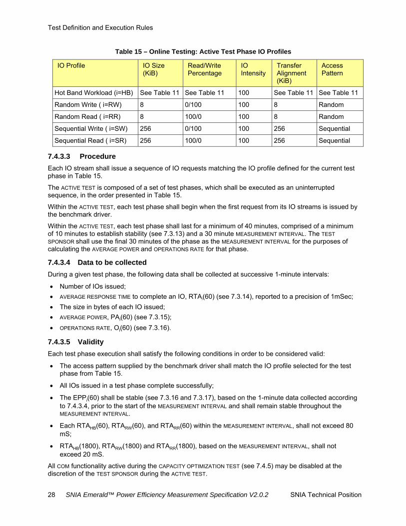
Test Definition and Execution Rules
28 SNIA Emerald™ Power Efficiency Measurement Specification V2.0.2 SNIA Technical Position
Table 15 – Online Testing: Active Test Phase IO Profiles
IO Profile IO Size (KiB)
Read/Write Percentage
IO Intensity
Transfer Alignment (KiB)
Access Pattern
Hot Band Workload (i=HB) See Table 11 See Table 11 100 See Table 11 See Table 11
Random Write ( i=RW) 8 0/100 100 8 Random
Random Read ( i=RR) 8 100/0 100 8 Random
Sequential Write ( i=SW) 256 0/100 100 256 Sequential
Sequential Read ( i=SR) 256 100/0 100 256 Sequential
7.4.3.3 Procedure
Each IO stream shall issue a sequence of IO requests matching the IO profile defined for the current test phase in Table 15.
The ACTIVE TEST is composed of a set of test phases, which shall be executed as an uninterrupted sequence, in the order presented in Table 15.
Within the ACTIVE TEST, each test phase shall begin when the first request from its IO streams is issued by the benchmark driver.
Within the ACTIVE TEST, each test phase shall last for a minimum of 40 minutes, comprised of a minimum of 10 minutes to establish stability (see 7.3.13) and a 30 minute MEASUREMENT INTERVAL. The TEST
SPONSOR shall use the final 30 minutes of the phase as the MEASUREMENT INTERVAL for the purposes of calculating the AVERAGE POWER and OPERATIONS RATE for that phase.
7.4.3.4 Data to be collected
During a given test phase, the following data shall be collected at successive 1-minute intervals:
Number of IOs issued;
AVERAGE RESPONSE TIME to complete an IO, RTAi(60) (see 7.3.14), reported to a precision of 1mSec;
The size in bytes of each IO issued;
AVERAGE POWER, PAi(60) (see 7.3.15);
OPERATIONS RATE, Oi(60) (see 7.3.16).
7.4.3.5 Validity
Each test phase execution shall satisfy the following conditions in order to be considered valid:
The access pattern supplied by the benchmark driver shall match the IO profile selected for the test phase from Table 15.
All IOs issued in a test phase complete successfully;
The EPPi(60) shall be stable (see 7.3.16 and 7.3.17), based on the 1-minute data collected according to 7.4.3.4, prior to the start of the MEASUREMENT INTERVAL and shall remain stable throughout the MEASUREMENT INTERVAL.
Each RTAHB(60), RTARW(60), and RTARR(60) within the MEASUREMENT INTERVAL, shall not exceed 80 mS;
RTAHB(1800), RTARW(1800) and RTARR(1800), based on the MEASUREMENT INTERVAL, shall not exceed 20 mS.
All COM functionality active during the CAPACITY OPTIMIZATION TEST (see 7.4.5) may be disabled at the discretion of the TEST SPONSOR during the ACTIVE TEST.

Test Definition and Execution Rules
SNIA Emerald™ Power Efficiency Measurement Specification V2.0.2 SNIA Technical Position 29
7.4.4 Ready Idle Test
7.4.4.1 Overview
The READY IDLE TEST shall begin immediately following the ACTIVE TEST.
7.4.4.2 Procedure
No FOREGROUND IO shall be initiated on the SUT during the READY IDLE TEST other than that required to satisfy the instrumentation requirements in 7.3.5.
AVERAGE POWER for this test phase is known as PARI(60), as defined by Equation 7-3.
The TEST SPONSOR may select the duration of the READY IDLE TEST, provided it is at least than two hours. The TEST SPONSOR shall use the final two hours of the test as the MEASUREMENT INTERVAL for the purposes of calculating the AVERAGE POWER.
7.4.5 Capacity Optimization Test
7.4.5.1 Overview
This sub-clause defines qualitative heuristics for validating the existence and activation of COMs that are present on the SUT. Each heuristic is a simple pass/fail test, intended to verify the presence and activation of a particular capacity optimization method.
7.4.5.2 Testing Requirements
The heuristics assess the impact on free space within a LUN to determine whether or not a COM is active and effective. The assessments rely on:
FSsot: free space at the start of a test;
FSeot: free space at the end of a test;
Sds: size of a data set (see 7.4.5.3);
Icom the impact of the COM on overall space utilization within the heuristic. The precise formulation of this value is defined by each heuristic.
TEST SPONSORs may select which of the heuristics they wish to execute. Only heuristics which are executed can be marked as passed (see 8.6.1).
If TEST SPONSORs choose to execute a heuristic, they shall execute all of its steps in sequence. The testing of storage equipment may have minimal interruptions between heuristic COMs as needed to set up for each selected heuristic test. No configuration changes are allowed between each heuristic test.
No STORAGE DEVICE may be added or removed, nor changed in state (taken on or offline, made a spare or incorporated, etc) nor may any RAID groups be changed during the CAPACITY OPTIMIZATION TEST. In the event of an automated disk failure and subsequent RAID rebuild at any time during a test, the test shall be restarted when the rebuild is completed and the failed disk replaced per manufacturers guidelines for installed and working systems.
7.4.5.3 Generating data sets
Prior to running the heuristics, up to three data sets shall be generated using a SNIA-supplied C program:
One that is completely uncompressible but can benefit from data deduplication,
One that is compressible but cannot benefit from data deduplication,
One that is completely irreducible.

Test Definition and Execution Rules
30 SNIA Emerald™ Power Efficiency Measurement Specification V2.0.2 SNIA Technical Position
The data sets will be created in a directory named "snia_capop_data" and will be approximately 2GB in size except for the dedupable data set which will be approximately 1GB. The names of the files are shown in Table 16.
Table 16 - Data Set Naming
Format File
Irreducible irreducible.dat
Compressible compressible.dat
Dedupable dedupable.dat
7.4.5.4 Delta Snapshot Heuristics
Delta snapshots in a storage system can be detected using a straightforward algorithm:
1. Query the free space before taking a snapshot;
2. Attempt to create a snapshot;
3. Write something to the snapshot in the case of a writeable one and then;
4. Query the free space after that snapshot to determine whether significant storage space has been used.
Read-only and writeable delta snapshots are treated separately so that systems that only do read-only snapshots may get credit for them.
7.4.5.4.1 Heuristic 1: Read-only delta snapshots
The method varies according to where the SUT places snapshots. Follow steps 1 or 2, and then proceed to step 3.
1. For a SUT which places snapshots in separate containers:
a. On the SUT, create two containers, each 15GB in size. The amount of actual physical storage that must be committed will vary by SUT, and should have been determined by the TEST
SPONSOR in prior trials before an official run of the test.
b. Mount the first container on a host, via any chosen protocol.
c. Determine the amount of free space FSsot available on the SUT as seen by the storage administrator.
d. Write the irreducible data set to the first container.
e. Perform a read-only delta snapshot of the first container and expose it through the second container, disabling any optional background copying mechanism. As an example, the snapshot of lun1 may be exposed as lun2.
f. Perform whatever steps are necessary to mount the second container as a file system. Open a small file on this file system (i.e., one of the files in the irreducible data set), and read some data from it, and close the file. Confirm that the file has been successfully read.
2. For a SUT which places snapshots on the originating container:
a. On the SUT, create a container of 15GB in size. The amount of actual physical storage that must be committed will vary by SUT, and should have been determined by the TEST SPO
b. NSOR in prior trials before an official run of the test.
c. Mount the container on the host via any chosen protocol.
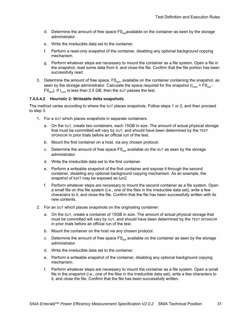
Test Definition and Execution Rules
SNIA Emerald™ Power Efficiency Measurement Specification V2.0.2 SNIA Technical Position 31
d. Determine the amount of free space FSsotavailable on the container as seen by the storage administrator.
e. Write the irreducible data set to the container.
f. Perform a read-only snapshot of the container, disabling any optional background copying mechanism.
g. Perform whatever steps are necessary to mount the container as a file system. Open a file in the snapshot, read some data from it, and close the file. Confirm that the file portion has been successfully read.
3. Determine the amount of free space, FSeot, available on the container containing the snapshot, as seen by the storage administrator. Calculate the space required for the snapshot (Icom = FSsot - FSeot). If Icom is less than 2.5 GB, then the SUT passes the test.
7.4.5.4.2 Heuristic 2: Writeable delta snapshots
The method varies according to where the SUT places snapshots. Follow steps 1 or 2, and then proceed to step 3.
1. For a SUT which places snapshots in separate containers:
a. On the SUT, create two containers, each 15GB in size. The amount of actual physical storage that must be committed will vary by SUT, and should have been determined by the TEST
SPONSOR in prior trials before an official run of the test.
b. Mount the first container on a host, via any chosen protocol.
c. Determine the amount of free space FSsot available on the SUT as seen by the storage administrator.
d. Write the irreducible data set to the first container.
e. Perform a writeable snapshot of the first container and expose it through the second container, disabling any optional background copying mechanism. As an example, the snapshot of lun1 may be exposed as lun2.
f. Perform whatever steps are necessary to mount the second container as a file system. Open a small file on this file system (i.e., one of the files in the irreducible data set), write a few characters to it, and close the file. Confirm that the file has been successfully written with its new contents.
2. For an SUT which places snapshots on the originating container:
a. On the SUT, create a container of 15GB in size. The amount of actual physical storage that must be committed will vary by SUT, and should have been determined by the TEST SPONSOR in prior trials before an official run of the test.
b. Mount the container on the host via any chosen protocol.
c. Determine the amount of free space FSsot available on the container as seen by the storage administrator.
d. Write the irreducible data set to the container.
e. Perform a writeable snapshot of the container, disabling any optional background copying mechanism.
f. Perform whatever steps are necessary to mount the container as a file system. Open a small file in the snapshot (i.e., one of the files in the irreducible data set), write a few characters to it, and close the file. Confirm that the file has been successfully written.

Test Definition and Execution Rules
32 SNIA Emerald™ Power Efficiency Measurement Specification V2.0.2 SNIA Technical Position
3. Determine the amount of free space FSeot available on the container containing the snapshot, as seen by the storage administrator. Calculate the space required for the snapshot (Icom = FSsot - FSeot). If Icom is less than 2.5 GB and the small file was successfully written onto the writeable delta snapshot destination, then the SUT passes the test.
7.4.5.5 Thin Provisioning Heuristics
The goal of this heuristic is not to highlight differences of thin provisioning implementations between vendors; it is to be used simply to ensure that the product under test does have some sort of thin provisioning capability. Therefore, a TEST SPONSOR seeking credit for thin provisioning shall:
1. Determine the amount of free space FSsot available on the SUT as seen by the storage administrator.
2. On the SUT, allocate a container 15GB in size.
3. Mount the container on the host mentioned in step (1), via any chosen file or blocks protocol, such as NFS or FC.
4. Write the irreducible data set to the container.
5. After a suitable amount of time, as specified by the TEST SPONSOR but not to exceed 1 hour, determine the amount of free space FSeot available on the SUT as seen by the storage administrator
6. Calculate the amount of formatted capacity used (Icom = FSsot – FSeot ) by the test. If Icom is less than 3GB, then the SUT passes the test.
7.4.5.6 Data Deduplication Heuristics
Data set size is not considered very important for the purposes of deduplication detection. This heuristic builds a 1GB dataset consisting of completely uncompressible blocks of data, and then uses it to detect deduplication. The initial dataset contains many duplicated files of various size and many duplicated blocks aligned on block boundaries. It also contains duplicated blocks of variable lengths that are not aligned on block boundaries. This allows detection of block-based schemes, variable-length schemes, and single-instance storage schemes.
A TEST SPONSOR seeking credit for deduplication of primary storage shall:
1. On the SUT, create a container 15GB in size. The amount of actual physical storage that must be committed will vary by SUT, and should have been determined by the TEST SPONSOR in prior trials before an official run of the test.
2. For a SUT exporting block storage, perform whatever steps are necessary to make the container visible on the host from which tests are being run, and create and mount a local file system on that container.
3. For a SUT exporting file storage, mount the container on the host via any chosen file protocol such as NFS or CIFS.
4. Determine the amount of free space FSsot available on the container as seen by the storage administrator.
5. Write the deduplication-reducible data set (dedupable.dat) to the container.
6. Wait a suitable amount of time as specified by the TEST SPONSOR for non-inline deduplication processes to have completed.
7. Determine the amount of free space FSeot available on the container as seen by the storage administrator.
8. Calculate the amount of formatted capacity saved by data deduplication (Icom = 1 – [ (FSeot - FSsot ) / Sds]) * 100%. If Icom is greater than 10%, then the SUT passes the test.

Test Definition and Execution Rules
SNIA Emerald™ Power Efficiency Measurement Specification V2.0.2 SNIA Technical Position 33
7.4.5.7 Parity RAID Heuristics
Capacity utilization and improvement relative to a comparable RAID-1 configuration--the relative storage efficiency ratio--is simple to calculate, given that RAID group sizes and parity requirements are simple and well known.
A TEST SPONSOR seeking credit for parity RAID shall:
1. Choose a RAID group configuration. Use the option with the highest capacity utilization. For example, if a product supports RAID 5 and RAID 6, use the configuration whose default size gives the best relative storage efficiency ratio. It is mandatory to use the default RAID group size for the given configuration.
2. Determine the number and capacity of the storage devices (e.g., hard disks) required to provision one RAID group of the default size for the system under test. Call the required number of drives D, and the number of parity drives P.
3. Calculate Icom = (D - P) / (D / 2). This is the relative storage efficiency of the RAID group compared to the assumed capacity utilization of a RAID-1 array configuration. The P value can be determined from Table 17. If Icom is greater than 1.0, then the SUT passes the test.
Table 17 - RAID and Parity Settings
RAID Level Parity (P value)
RAID-5 P=1
RAID-6 P=2
7.4.5.8 Compression Heuristics
The heuristic is accomplished by provisioning an empty container and storing the reference data sets onto it, then determining the actual amount of space used for storing the data.
A TEST SPONSOR seeking credit for advanced compression shall:
1. On the SUT, create a container 15GB in size. The amount of actual physical storage that must be committed will vary by SUT, and should have been determined by the TEST SPONSOR in prior trials before an official run of the test.
2. For a SUT exporting block storage, perform whatever steps are necessary to make the first container visible on the host from which tests are being run, and create and mount a local file system on that container.
3. For a SUT exporting file storage, mount the container on the host via any chosen file protocol such as NFS or CIFS.
4. Determine the amount of free space FSsot available on the container as seen by the storage administrator.
5. Write the compression-reducible data set (compressible.dat) to the container.
6. Wait a suitable amount of time as specified by the TEST SPONSOR for non-inline compression to have completed.
7. Determine the amount of free space FSeot available on the container as seen by the storage administrator.
8. Calculate the amount of formatted capacity saved by compression (Icom = 1 – [ (FSeot - FSsot ) / Sds]) *100%. If Icom is greater than 10%, then the SUT passes the test.

Test Definition and Execution Rules
34 SNIA Emerald™ Power Efficiency Measurement Specification V2.0.2 SNIA Technical Position
7.5 Near Online Testing
7.5.1 Pre-fill
7.5.1.1 Overview
The sut pre-fill stage is intended to provide a working data set on the storage system to be used with the other testing sets. The SUT should have a minimum of 56% of the raw storage pre-filled before continuing to the SUT Conditioning Test.
7.5.1.2 Pre-fill Stage Procedure
Follow these guidelines and requirements:
Allocated storage space of the SUT shall be a minimum of 70% of raw capacity.
The SUT logical allocated address space shall be pre-filled with the IO pattern described in Table 18 such that 80% of the allocated storage is filled with data.
The data used to pre-fill the SUT will be a 2:1 compression pattern.
Each IO stream shall issue each IO request synchronously, with each subsequent IO request issued immediately following the completion of its predecessor.
The SUT PRE-FILL shall begin when the first request from the IO streams is issued by the benchmark driver. The duration of the SUT PRE-FILL shall be disclosed.
IO transfer size and alignment picked by TEST SPONSOR shall be disclosed.
The following test phases shall only access the allocated storage space that has pre-filled data.
The SUT pre-fill test shall last for a minimum amount of time required to reach the pre-fill requirements of the SUT. The full duration shall be disclosed.
Table 18 Pre-fill Test Phase IO Profiles
IO Profile Read/Write Percentage
IO Intensity
Access Pattern
Sequential Write 0/100 100 Sequential
7.5.2 SUT Conditioning Test
7.5.2.1 Overview
The SUT CONDITIONING TEST is intended to provide a uniform initial condition for subsequent measurement(s) and to:
Demonstrate the SUT‘s ability to process IO requests;
Ensure that each STORAGE DEVICE in the SUT is fully operational and capable of satisfying all supported requests within the constraints of the taxonomy classification identified for the SUT;
Achieve typical operating temperature.
The limitations of timely benchmark execution make it impossible to remove all variability between results, or to provide complete pre-testing stability. TEST SPONSORS are encouraged to minimize the impact of certain long-duration or infrequent changes to the SUT that can impact test results, including:
Cache stability,
Maintenance cycles.

Test Definition and Execution Rules
SNIA Emerald™ Power Efficiency Measurement Specification V2.0.2 SNIA Technical Position 35
7.5.2.2 Procedure
Each IO stream shall issue each IO request synchronously, with each subsequent IO request issued immediately following the completion of its predecessor.
The SUT CONDITIONING TEST shall begin when the first request from the IO streams is issued by the benchmark driver. The duration of the SUT CONDITIONING TEST shall be disclosed.
The benchmark driver shall initiate a number of independent IO streams equal to or greater than the number of LUNS made available to the benchmark driver by the SUT.
Each IO stream shall issue a sequence of IO requests with the IO profile shown in Table 19.
Table 19 – Near Online: SUT Conditioning Test Phase IO Profiles
IO Profile Read/Write Percentage
IO Intensity Access Pattern
Hot banding See Table 11
100 See Table 11
If the SUT includes functionality that requires changes to the IO profile defined in Table 19 in order to meet the intent stated in 7.5.2.1, the changes shall be disclosed.
The SUT CONDITIONING TEST shall last for a minimum of 12 hours. The duration shall be disclosed.
7.5.2.3 Data to be collected
During the SUT CONDITIONING TEST, the following data shall be collected at successive 1-minute intervals:
Number of IOs issued;
Average response time to complete an IO, RTA(60) (see 7.3.14), reported to a precision of 1mSec;
The size in bytes of each IO issued.
AVERAGE POWER, PAsc(60) (see 7.3.15).
7.5.2.4 Validity
The SUT CONDITIONING TEST shall be considered valid if all IOs issued complete successfully.
7.5.3 Active Test
7.5.3.1 Overview
The ACTIVE TEST shall begin immediately following the SUT CONDITIONING TEST.
Each test phase shall launch a TEST-SPONSOR-selected number of independent IO streams.
Each IO stream shall issue its IO requests synchronously, with each subsequent IO request issued immediately following the completion of its predecessor. All IO operations shall transfer data, either reading or writing. The IO stream does not include any idle or “think time.”

Test Definition and Execution Rules
36 SNIA Emerald™ Power Efficiency Measurement Specification V2.0.2 SNIA Technical Position
7.5.3.2 Test Phases
Table 20 defines the sequence of test phases, and their associated IO profiles, for this test.
Table 20 – Near Online: Active Test Phase IO Profiles
IO Profile IO Size (KiB)
Read/Write Percentage
IO Intensity
Transfer Alignment (KiB)
Access Pattern
Hot Band Workload (i=HB) See Table 11 See Table 11 100 See Table 11 See Table 11
Random Write ( i=RW) 8 0/100 100 8 Random
Random Read ( i=RR) 8 100/0 100 8 Random
Sequential Write ( i=SW) 256 0/100 100 256 Sequential
Sequential Read ( i=SR) 256 100/0 100 256 Sequential
7.5.3.3 Procedure
Each IO stream shall issue a sequence of IO requests matching the IO profile defined for the current test phase in Table 20.
The ACTIVE TEST is composed of a set of test phases, which shall be executed as an uninterrupted sequence, in the order presented in Table 20.
Within the ACTIVE TEST, each test phase shall begin when the first request from its IO streams is issued by the benchmark driver.
Within the ACTIVE TEST, each test phase shall last for a minimum of 40 minutes comprised of a minimum of 10 minutes to establish stability (see 7.3.13) and a 30 minute measurement interval. The TEST SPONSOR shall use the final 30 minutes of the phase as the MEASUREMENT INTERVAL for the purposes of calculating the AVERAGE POWER and OPERATIONS RATE for that phase.
7.5.3.4 Data to be collected
During a given test phase, the following data shall be collected at successive 1-minute intervals:
Number of IOs issued;
Average response time to complete an IO, RTA(60) (see 7.3.14), reported to a precision of 1mSec;
The size in bytes of each IO issued.
AVERAGE POWER, PAi(60) (see 7.3.15);
OPERATIONS RATE, Oi(60) (see 7.3.16).
7.5.3.5 Validity
Each test phase execution shall satisfy the following conditions in order to be considered valid:
All IOs issued in a test phase complete successfully.
The access pattern supplied by the benchmark driver shall match the IO profile selected for the test phase from Table 20.
The EPPi(60) shall be stable (see 7.3.16 and 7.3.17), based on the 1-minute data collected according to 7.5.3.4 prior to the start of the MEASUREMENT INTERVAL and shall remain stable throughout the MEASUREMENT INTERVAL.

Test Definition and Execution Rules
SNIA Emerald™ Power Efficiency Measurement Specification V2.0.2 SNIA Technical Position 37
All COM functionality active during the CAPACITY OPTIMIZATION TEST (see 7.5.5) shall be active during the ACTIVE TEST.
7.5.3.6 Timing Requirements
This taxonomy category assumes an intermittent access pattern, with possibly protracted periods of inactivity, and a correspondingly longer MaxTTFD. Given the non-transactional nature of this access, no average response time requirement is defined for this category.
7.5.4 Ready Idle Test
7.5.4.1 Overview
The READY IDLE TEST shall begin immediately following the ACTIVE TEST.
7.5.4.2 Procedure
No FOREGROUND IO shall be initiated on the SUT during the READY IDLE TEST other than that required to satisfy the instrumentation requirements in 7.3.5.
AVERAGE POWER for this test phase is known as PARI(60), as defined by Equation 7-3.
The TEST SPONSOR may select the duration of the READY IDLE TEST, provided it is at least than two hours. The TEST SPONSOR shall use the final two hours of the test as the measurement interval for the purposes of calculating the AVERAGE POWER.
7.5.5 Capacity Optimization Test
7.5.5.1 Overview
This sub-clause defines qualitative heuristics for validating the existence and activation of COMs that are present on the SUT. Each heuristic is a simple pass/fail test, intended to verify the presence and activation of a particular capacity optimization method.
7.5.5.2 Testing Requirements
The heuristics assess the impact on free space within a LUN to determine whether or not a COM is active and effective. The assessments rely on:
FSsot: free space at the start of a test;
FSeot: free space at the end of a test;
Sds: size of a data set (see 7.5.5.3
Icom the impact of the COM on overall space utilization within the heuristic. The precise formulation of this value is defined by each heuristic.
TEST SPONSORs may select which of the heuristics they wish to execute. Only heuristics which are executed can be marked as passed (see 8.6.1).
If TEST SPONSORs choose to execute a heuristic, they shall execute all of its steps in sequence.
No STORAGE DEVICE may be added or removed, nor changed in state (taken on or offline, made a spare or incorporated, etc) nor may any RAID groups be changed during the CAPACITY OPTIMIZATION TEST. In the event of an automated disk failure and subsequent RAID rebuild at any time during a test, the test shall be restarted when the rebuild is completed and the failed disk replaced per manufacturers guidelines for installed and working systems.

Test Definition and Execution Rules
38 SNIA Emerald™ Power Efficiency Measurement Specification V2.0.2 SNIA Technical Position
7.5.5.3 Data Sets
Prior to running the heuristics, up to three data sets shall be generated using a SNIA-supplied C program:
one that is completely uncompressible but can benefit from data deduplication,
one that is compressible but cannot benefit from data deduplication,
one that is completely irreducible.
The data sets will be created in a directory named "snia_capop_data" and will be approximately 2GB in size except for the dedupable data set which will be approximately 1GB. The names of the files are shown in Table 21.
Table 21 - Data Set Naming
Format File
irreducible irreducible.dat
compressible compressible.dat
dedupable dedupable.dat
7.5.5.4 Delta Snapshot Heuristics
Delta snapshots in a storage system can be detected using a straightforward algorithm:
1. Query the free space before taking a snapshot.
2. Attempt to create a snapshot.
3. Write something to the snapshot in the case of a writeable one and then.
4. Query the free space after that snapshot to determine whether significant storage space has been used.
Read-only and writeable delta snapshots are treated separately so that systems that only do read-only snapshots may get credit for them.
7.5.5.4.1 Heuristic 1: Read-only delta snapshots
The method varies according to where the SUT places snapshots. Follow steps 1 or 2, and then proceed to step 3.
1. For a SUT which places snapshots in separate containers:
a. On the SUT, create two containers, each 15GB in size. The amount of actual physical storage that must be committed will vary by SUT, and should have been determined by the TEST
SPONSOR in prior trials before an official run of the test.
b. Mount the first container on a host, via any chosen protocol.
c. Determine the amount of free space FSsot available on the SUT as seen by the storage administrator.
d. Write the irreducible data set to the first container.
e. Perform a writeable delta snapshot of the first container and expose it through the second container, disabling any optional background copying mechanism. As an example, the snapshot of lun1 may be exposed as lun2.
f. Perform whatever steps are necessary to mount the second container as a file system. Open a small file on this file system, write a few characters to it and read some data from it, and close the file. Confirm that the file has been successfully written read with its new contents.
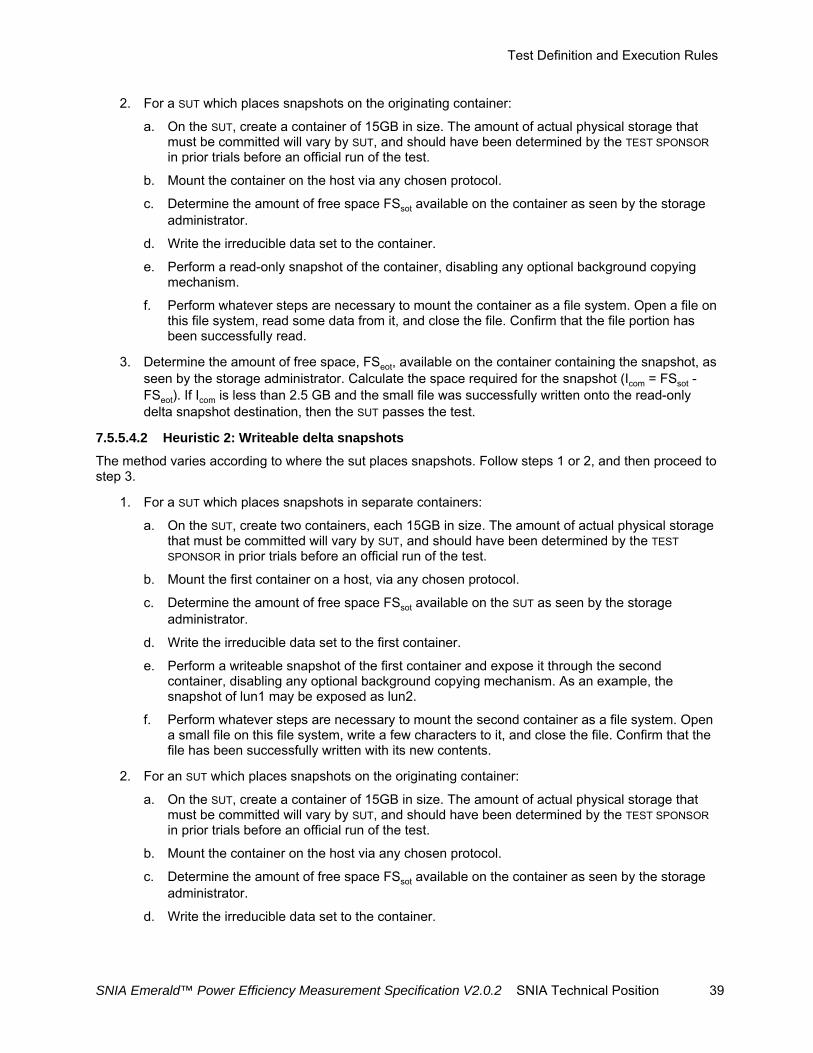
Test Definition and Execution Rules
SNIA Emerald™ Power Efficiency Measurement Specification V2.0.2 SNIA Technical Position 39
2. For a SUT which places snapshots on the originating container:
a. On the SUT, create a container of 15GB in size. The amount of actual physical storage that must be committed will vary by SUT, and should have been determined by the TEST SPONSOR in prior trials before an official run of the test.
b. Mount the container on the host via any chosen protocol.
c. Determine the amount of free space FSsot available on the container as seen by the storage administrator.
d. Write the irreducible data set to the container.
e. Perform a read-only snapshot of the container, disabling any optional background copying mechanism.
f. Perform whatever steps are necessary to mount the container as a file system. Open a file on this file system, read some data from it, and close the file. Confirm that the file portion has been successfully read.
3. Determine the amount of free space, FSeot, available on the container containing the snapshot, as seen by the storage administrator. Calculate the space required for the snapshot (Icom = FSsot - FSeot). If Icom is less than 2.5 GB and the small file was successfully written onto the read-only delta snapshot destination, then the SUT passes the test.
7.5.5.4.2 Heuristic 2: Writeable delta snapshots
The method varies according to where the sut places snapshots. Follow steps 1 or 2, and then proceed to step 3.
1. For a SUT which places snapshots in separate containers:
a. On the SUT, create two containers, each 15GB in size. The amount of actual physical storage that must be committed will vary by SUT, and should have been determined by the TEST
SPONSOR in prior trials before an official run of the test.
b. Mount the first container on a host, via any chosen protocol.
c. Determine the amount of free space FSsot available on the SUT as seen by the storage administrator.
d. Write the irreducible data set to the first container.
e. Perform a writeable snapshot of the first container and expose it through the second container, disabling any optional background copying mechanism. As an example, the snapshot of lun1 may be exposed as lun2.
f. Perform whatever steps are necessary to mount the second container as a file system. Open a small file on this file system, write a few characters to it, and close the file. Confirm that the file has been successfully written with its new contents.
2. For an SUT which places snapshots on the originating container:
a. On the SUT, create a container of 15GB in size. The amount of actual physical storage that must be committed will vary by SUT, and should have been determined by the TEST SPONSOR in prior trials before an official run of the test.
b. Mount the container on the host via any chosen protocol.
c. Determine the amount of free space FSsot available on the container as seen by the storage administrator.
d. Write the irreducible data set to the container.

Test Definition and Execution Rules
40 SNIA Emerald™ Power Efficiency Measurement Specification V2.0.2 SNIA Technical Position
e. Perform a writeable snapshot of the container, disabling any optional background copying mechanism.
f. Perform whatever steps are necessary to mount the container as a file system. Open a small file on this file system, write a few characters to it, and close the file. Confirm that the file has been successfully written.
3. Determine the amount of free space FSeot available on the container containing the snapshot, as seen by the storage administrator. Calculate the space required for the snapshot (Icom = FSsot - FSeot). If Icom is less than 2.5 GB and the small file was successfully written onto the writeable delta snapshot destination, then the SUT passes the test.
7.5.5.5 Thin Provisioning Heuristics
The goal of this heuristic is not to highlight differences of thin provisioning implementations between vendors; it is to be used simply to ensure that the product under test does have some sort of thin provisioning capability. Therefore, a TEST SPONSOR seeking credit for thin provisioning shall:
1. Determine the amount of free space FSsot available on the SUT as seen by the storage administrator.
2. On the SUT, allocate a container 15GB in size.
3. Mount the container on the host mentioned in step (1), via any chosen file or blocks protocol, such as NFS or FC.
4. Write the irreducible data set to the container.
5. After a suitable amount of time, as specified by the TEST SPONSOR but not to exceed 1 hour, determine the amount of free space FSeot available on the SUT as seen by the storage administrator.
6. Calculate the amount of formatted capacity used (Icom = FSsot – FSeot ) by the test. If Icom is less than 3GB, then the SUT passes the test.
7.5.5.6 Data Deduplication Heuristics
Data set size is not considered very important for the purposes of deduplication detection. This heuristic builds a 1GB dataset consisting of completely uncompressible blocks of data, and then uses it to detect deduplication. The initial dataset contains many duplicated files of various size and many duplicated blocks aligned on block boundaries. It also contains duplicated blocks of variable lengths that are not aligned on block boundaries. This allows detection of block-based schemes, variable-length schemes, and single-instance storage schemes.
A TEST SPONSOR seeking credit for deduplication of primary storage shall:
1. On the SUT, create a container 15GB in size. The amount of actual physical storage that must be committed will vary by SUT, and should have been determined by the TEST SPONSOR in prior trials before an official run of the test.
2. For a SUT exporting block storage, perform whatever steps are necessary to make the container visible on the host from which tests are being run, and create and mount a local file system on that container.
3. For a SUT exporting file storage, mount the container on the host via any chosen file protocol such as NFS or CIFS.
4. Determine the amount of free space FSsot available on the container as seen by the storage administrator.
5. Write the deduplication-reducible data set to the container.

Test Definition and Execution Rules
SNIA Emerald™ Power Efficiency Measurement Specification V2.0.2 SNIA Technical Position 41
6. Wait a suitable amount of time as specified by the TEST SPONSOR for non-inline compression and deduplication processes to have completed.
7. Determine the amount of free space FSeot available on the container as seen by the storage administrator.
8. Calculate the amount of formatted capacity saved by data deduplication (Icom = 1 – [ (FSsot - FSeot ) / Sds]) * 100%. If Icom is greater than 10%, then the SUT passes the test.
7.5.5.7 Parity RAID Heuristics
Capacity utilization and improvement relative to a comparable RAID-1 configuration--the relative storage efficiency ratio--is simple to calculate, given that RAID group sizes and parity requirements are simple and well known.
A TEST SPONSOR seeking credit for advanced RAID shall:
1. Choose a RAID group configuration. Use the option with the highest capacity utilization. For example, if a product supports RAID 5 and RAID 6, use the configuration whose default size gives the best relative storage efficiency ratio. It is mandatory to use the default RAID group size for the given configuration.
2. Determine the number and capacity of the storage devices (e.g., hard disks) required to provision one RAID group of the default size for the system under test. Call the required number of drives D, and the number of parity drives P.
3. Calculate Icom = (D - P) / (D / 2). This is the relative storage efficiency of the RAID group compared to the assumed capacity utilization of a RAID-1 array configuration. The P value can be determined from Table 22. If Icom is greater than 1.0, then the SUT passes the test.
Table 22 - RAID and Parity Settings
RAID Level Parity (P value)
RAID-5 P=1
RAID-6 P=2
7.5.5.8 Compression Heuristics
The heuristic is accomplished by provisioning an empty container and storing the reference data sets onto it, then determining the actual amount of space used for storing the data.
A TEST SPONSOR seeking credit for advanced compression shall:
1. On the SUT, create a container 15GB in size. The amount of actual physical storage that must be committed will vary by SUT, and should have been determined by the TEST SPONSOR in prior trials before an official run of the test.
2. For a SUT exporting block storage, perform whatever steps are necessary to make the first container visible on the host from which tests are being run, and create and mount a local file system on that container.
3. For a SUT exporting file storage, mount the container on the host via any chosen file protocol such as NFS or CIFS.
4. Determine the amount of free space FSsot available on the container as seen by the storage administrator.
5. Write the compression-reducible data set to the container.
6. Wait a suitable amount of time as specified by the TEST SPONSOR for non-inline compression and deduplication processes to have completed.

Test Definition and Execution Rules
42 SNIA Emerald™ Power Efficiency Measurement Specification V2.0.2 SNIA Technical Position
7. Determine the amount of free space FSeot available on the container as seen by the storage administrator.
8. Calculate the amount of formatted capacity saved by compression (Icom = 1 – [ (FSsot - FSeot ) / Sds]) *100%. If Icom is greater than 10%, then the SUT passes the test.
7.6 Removable Media Library Testing
7.6.1 SUT Configuration
The SUT shall include the number of removable media drives given for the selected taxonomy category in Table 23. There shall be no change to the number of drives in the SUT during the tests.
Table 23 - Required Drive Counts
Category Required Drive Count
Removable-1 Maximum supported
Removable-2 Maximum Supported
Removable-3 Maximum Supported
Removable-4 24
Removable-5 24
7.6.2 Pre-fill Test
There are no pre-fill requirements for removable media library testing.
All writes by the benchmark driver shall be 8-bit random data.
7.6.3 SUT Conditioning Test
7.6.3.1 Overview
The SUT CONDITIONING TEST is intended to provide a uniform initial condition for subsequent measurement(s) and to:
Demonstrate the SUT‘s ability to process IO requests;
Ensure that each STORAGE DEVICE in the SUT is fully operational and capable of satisfying all supported requests within the constraints of the taxonomy classification identified for the SUT;
Achieve typical operating temperature.
The limitations of timely benchmark execution make it impossible to remove all variability between results, or to provide complete pre-testing stability. TEST SPONSORS are encouraged to minimize the impact of certain long-duration or infrequent changes to the SUT that can impact test results, including:
Cache STABILITY,
MAINTENANCE cycles.
7.6.3.2 Procedure
Each IO stream shall issue each IO request synchronously, with each subsequent IO request issued immediately following the completion of its predecessor.
The SUT CONDITIONING TEST shall begin when the first request from the IO streams is issued by the benchmark driver. The duration of the SUT CONDITIONING TEST shall be disclosed.

Test Definition and Execution Rules
SNIA Emerald™ Power Efficiency Measurement Specification V2.0.2 SNIA Technical Position 43
The benchmark driver shall uniformly distribute the required IO requests among the IO streams, such that the maximum number of IO requests serviced by an IO stream is no more than 10% greater than minimum number of IO requests serviced by an IO stream.
The TEST SPONSOR shall ensure that all tape/optical drives are accessed at some time during the SUT
CONDITIONING TEST.
The benchmark driver shall initiate a number of independent IO streams equal to or greater than the number of tape/optical drives made available to the benchmark driver by the SUT.
7.6.3.3 Phases
The SUT CONDITIONING TEST shall consist of two phases, each lasting for a minimum of seven minutes. The duration of each phase shall be disclosed. If the duration of either test phase is longer than the 7 minutes, the TEST SPONSOR shall designate the final 7 minutes of that test phase as the MEASUREMENT INTERVAL for that test phase.
7.6.3.4 Tape/optical Drives
The TEST SPONSOR shall ensure that all tape/optical drives are:
Loaded prior to the SUT CONDITIONING TEST
Rewound between the two phases of the SUT CONDITIONING TEST
Rewound at the end of the SUT CONDITIONING TEST
7.6.3.5 IO Profiles
Table 24 - Removable Media Library Testing: SUT Conditioning Test IO Profiles
IO Profile IO Size (KiB)
Read/ Write Percentage
IO Intensity
Transfer Alignment (KiB)
Access Pattern
Sequential Write ( i=C1) 256 0/100 100 256 Sequential
Sequential Read (i=C2) 256 100/0 100 256 Sequential
Each IO stream shall issue a sequence of IO requests satisfying the Sequential Write IO profile shown in Table 24 during the first phase of the SUT CONDITIONING TEST, and the Sequential Read IO profile shown in Table 24 during the second phase of the SUT CONDITIONING TEST.
If the SUT includes functionality that requires changes to the IO profile defined in Table 24 in order to meet the intent stated in 7.6.3.1, the changes shall be disclosed.
7.6.3.6 Data to be Collected
During the SUT CONDITIONING TEST, the following data shall be collected at 1-minute intervals:
Number of IOs issued;
Average response time to complete an IO, RTA(60) (see 7.3.14), reported to a precision of 1mSec;
The size in bytes of each IO issued;
AVERAGE POWER, PAi(60) (see 7.3.15).
7.6.3.7 Validity
The SUT CONDITIONING TEST shall be considered valid if all IOs issued in a test phase complete successfully.

Test Definition and Execution Rules
44 SNIA Emerald™ Power Efficiency Measurement Specification V2.0.2 SNIA Technical Position
7.6.4 Active Test
7.6.4.1 Overview
The ACTIVE TEST shall begin immediately following the SUT CONDITIONING TEST.
7.6.4.2 Procedure
Each test phase shall launch a number of independent IO streams equal to the number of drives present in the SUT. All drives in the SUT shall be capable of processing IO requests at the start of a test phase.
Each IO stream shall issue its IO requests synchronously, with each subsequent IO request issued immediately following the completion of its predecessor. All IO operations transfer data, either reading or writing. The IO stream does not include any idle or “think time.”
Equation 7-5: Sequential Transfer Offset
RMODSOO nn
1
Where: On is an IO offset S is the IO size R is the FORMATTED CAPACITY of the SUT.
7.6.4.3 Sequential Access
The first IO within a sequential IO Stream shall use occur at Beginning of Tape (BOT). Each subsequent IO request shall be sent to and satisfied by the SUT in sequence using a transfer offset that satisfies Equation 7-5.
The benchmark driver shall uniformly distribute the required IO requests among the IO streams, such that the maximum number of IO requests serviced by an IO stream is no more than 10% greater than minimum number of IO requests serviced by an IO stream.
The TEST SPONSOR shall ensure that tape drives are accessed at some time during the ACTIVE TEST.
Table 25 - Removable Media Library Testing: Active Test Phase IO Profiles
IO Profile IO Size (KiB)
Read/Write Percentage
IO Intensity Transfer Alignment (KiB)
Access Pattern
Sequential Write (I=SW)
256 0/100 100 256 Sequential
Sequential Read (I=SR)
256 100/0 100 256 Sequential
Table 25 defines the sequence of test phases, and their associated IO profiles, used during this test.
Each IO stream shall issue a sequence of IO requests matching the profile defined for the current test phase in Table 25.
7.6.4.4 Test Phases
The ACTIVE TEST is composed of two test phases, which shall be executed as an uninterrupted sequence, and separated by a rewind to Beginning of Tape (BOT), in the order presented in Table 25.
Within the ACTIVE TEST, each test phase shall begin when the first request from its IO streams is issued by the benchmark driver.
Within the ACTIVE TEST, each test phase shall last for a minimum of 40 minutes, comprised of a minimum of 10 minutes to establish stability (see 7.3.13) and a 30 minute MEASUREMENT INTERVAL. The TEST

Test Definition and Execution Rules
SNIA Emerald™ Power Efficiency Measurement Specification V2.0.2 SNIA Technical Position 45
SPONSOR shall use the final 30 minutes of the phase as the MEASUREMENT INTERVAL for the purposes of calculating the AVERAGE POWER and OPERATIONS RATE for that phase.
7.6.4.4.1 Data to be Collected
During a given test phase, the following data shall be collected at successive one minute intervals:
Average data rate reported for each drive, reported in MiB/s;
AVERAGE POWER, PAi(60) (see 7.3.15);
OPERATIONS RATE, Oi(60) (see 7.3.16).
7.6.4.4.2 Test Phase Conditions
Each test phase execution shall satisfy the following conditions in order to be considered valid:
All IOs issued in a test phase complete successfully;
The access pattern supplied by the benchmark driver shall match the IO profile selected for the test phase from Table 25;
The EPPi(60) shall be stable (see 7.3.16 and 7.3.17), based on the 1-minute data collected according to 7.6.4.4.1, prior to the start of the MEASUREMENT INTERVAL and shall remain stable throughout the MEASUREMENT INTERVAL.
7.6.4.5 Data Rate
The overall data rate for each drive used in a given configuration is defined to be the average of the average data rates collected for that drive according to 7.6.4.4.1.
The OVERALL DATA RATE for each drive present in the SUT for a given test phase shall be greater than or equal to 80% of the maximum published data rate for that drive type.
7.6.4.6 Tape Robots
If the SUT contains tape robots, they shall be enabled and ready to process a tape manipulation commands throughout the ACTIVE TEST.
7.6.4.7 Drive-level Compression
If the SUT supports drive-level compression, it shall be disabled throughout the active test.
7.6.4.8 Timing Requirements
Not defined.
7.6.5 Ready Idle Test
The READY IDLE TEST shall begin immediately following the ACTIVE TEST.
No FOREGROUND IO shall be initiated on the SUT during the READY IDLE TEST other than that required to satisfy the instrumentation requirements in 7.3.5.
AVERAGE POWER for this test phase is known as PARI(60), as defined by Equation 7-3.
The TEST SPONSOR may select the duration of the READY IDLE TEST, provided it is at least than two hours. The TEST SPONSOR shall use the final two hours of the test as the MEASUREMENT INTERVAL for the purposes of calculating the AVERAGE POWER.
The READY IDLE TEST shall begin after any loaded STORAGE DEVICES have been unloaded from the tape drives and any robotics activity has completed.

Test Definition and Execution Rules
46 SNIA Emerald™ Power Efficiency Measurement Specification V2.0.2 SNIA Technical Position
7.6.6 Capacity Optimization Test
This specification does not define a CAPACITY OPTIMIZATION METHOD TEST for the Removable Media Library taxonomy category.
7.7 Virtual Media Library Testing
7.7.1 Pre-fill
There are no pre-fill requirements for removable media library testing.
All writes by the benchmark driver shall be 8-bit random data.
7.7.2 SUT Conditioning Test
7.7.2.1 Overview
The SUT CONDITIONING TEST of a SNIA Emerald™ Power Efficiency Measurement is intended to provide a uniform initial condition for subsequent measurement(s) and to:
Demonstrate the SUT‘s ability to process IO requests;
Ensure that each STORAGE DEVICE in the SUT is fully operational and capable of satisfying all supported requests within the constraints of the taxonomy classification identified for the SUT;
Achieve typical operating temperature.
The limitations of timely benchmark execution make it impossible to remove all variability between results, or to provide complete pre-testing stability. TEST SPONSORS are encouraged to minimize the impact of certain long-duration or infrequent changes to the SUT that can impact test results, including:
Cache stability,
Maintenance cycles.
7.7.2.2 Procedure
Each IO stream shall issue each IO request synchronously, with each subsequent IO request issued immediately following the completion of its predecessor.
The SUT CONDITIONING TEST shall begin when the first request from the IO streams is issued by the benchmark driver. The duration of the SUT CONDITIONING TEST shall be disclosed.
The benchmark driver shall uniformly distribute the required IO requests among the IO streams, such that the maximum number of IO requests serviced by an IO stream is no more than 10% greater than minimum number of IO requests serviced by an IO stream.
The TEST SPONSOR shall ensure that all STORAGE DEVICES are accessed at some time during the SUT
CONDITIONING TEST.
The benchmark driver shall initiate a number of independent IO streams equal to or greater than the number of VIRTUAL DRIVES made available to the benchmark driver by the SUT.
7.7.2.3 Phases
The SUT CONDITIONING TEST shall consist of two phases, each lasting for a minimum of 7 minutes. The duration of each phase shall be disclosed. If the duration of either test phase is longer than the 7 minutes, the TEST SPONSOR shall designate the final 7 minutes of that test phase as the MEASUREMENT INTERVAL for that test phase.

Test Definition and Execution Rules
SNIA Emerald™ Power Efficiency Measurement Specification V2.0.2 SNIA Technical Position 47
7.7.2.4 Virtual Drives
The TEST SPONSOR shall ensure that all VIRTUAL DRIVES are:
Loaded prior to the sut conditioning test,
Rewound between the two phases of the sut conditioning test,
Rewound at the end of the SUT CONDITIONING TEST.
Table 26 - Virtual Media Library Testing: SUT Conditioning Test IO Profiles
IO Profile IO Size (KiB)
Read/ Write Percentage
IO Intensity
Transfer Alignment (KiB)
Access Pattern
Sequential Write (i=C1)
256 0/100 100 256 Sequential
Sequential Read (i=C2)
256 100/0 100 256 Sequential
7.7.2.5 Sequence
Each IO stream shall issue a sequence of IO requests satisfying the Sequential Write IO profile shown in Table 26 during the first phase of the SUT CONDITIONING TEST, and the Sequential Read IO profile shown in Table 26 during the second phase of the SUT CONDITIONING TEST
If the SUT includes functionality that requires changes to the IO profile defined Table 26 in order to meet the intent stated in 7.7.2.1, the changes shall be disclosed.
7.7.2.6 Data to be Collected
During the SUT CONDITIONING TEST, the following data shall be collected at successive 1-minute intervals:
Number of IOs issued;
Average response time to complete an IO, RTAi(60), reported to a precision of 1mSec;
The size in bytes of each IO issued.
AVERAGE POWER, PAi(60) (see 7.3.15)
7.7.2.7 Validity
The SUT CONDITIONING TEST shall be considered valid if all IOs issued in a test phase complete successfully.
7.7.3 Active Test
The ACTIVE TEST shall begin immediately following the SUT CONDITIONING TEST.
During the ACTIVE TEST, the SUT shall include a number of VIRTUAL DRIVES that is sufficient to reach 80% of maximum published data rate for the drive type being emulated. There shall be no change to the number of VIRTUAL DRIVES in the SUT between the sequential write and sequential read test phases.
Each test phase shall launch a number of independent IO streams equal to the number of VIRTUAL DRIVES present in the SUT. All VIRTUAL DRIVES in the SUT shall be capable of processing IO requests prior to the start of a test phase.
Each IO stream shall issue its IO requests synchronously, with each subsequent IO request issued immediately following the completion of its predecessor. All IO operations shall transfer data, either reading or writing. The IO stream does not include any idle or “think time.”
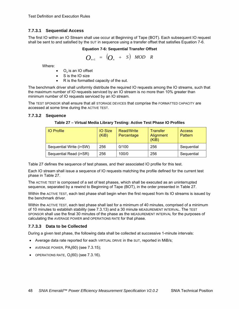
Test Definition and Execution Rules
48 SNIA Emerald™ Power Efficiency Measurement Specification V2.0.2 SNIA Technical Position
7.7.3.1 Sequential Access
The first IO within an IO Stream shall use occur at Beginning of Tape (BOT). Each subsequent IO request shall be sent to and satisfied by the SUT in sequence using a transfer offset that satisfies Equation 7-6.
Equation 7-6: Sequential Transfer Offset
RMODSOO nn
1
Where: On is an IO offset S is the IO size R is the formatted capacity of the sut.
The benchmark driver shall uniformly distribute the required IO requests among the IO streams, such that the maximum number of IO requests serviced by an IO stream is no more than 10% greater than minimum number of IO requests serviced by an IO stream.
The TEST SPONSOR shall ensure that all STORAGE DEVICES that comprise the FORMATTED CAPACITY are accessed at some time during the ACTIVE TEST.
7.7.3.2 Sequence
Table 27 – Virtual Media Library Testing: Active Test Phase IO Profiles
IO Profile IO Size (KiB)
Read/Write Percentage
Transfer Alignment (KiB)
Access Pattern
Sequential Write (i=SW) 256 0/100 256 Sequential
Sequential Read (i=SR) 256 100/0 256 Sequential
Table 27 defines the sequence of test phases, and their associated IO profile for this test.
Each IO stream shall issue a sequence of IO requests matching the profile defined for the current test phase in Table 27.
The ACTIVE TEST is composed of a set of test phases, which shall be executed as an uninterrupted sequence, separated by a rewind to Beginning of Tape (BOT), in the order presented in Table 27.
Within the ACTIVE TEST, each test phase shall begin when the first request from its IO streams is issued by the benchmark driver.
Within the ACTIVE TEST, each test phase shall last for a minimum of 40 minutes, comprised of a minimum of 10 minutes to establish stability (see 7.3.13) and a 30 minute MEASUREMENT INTERVAL. The TEST
SPONSOR shall use the final 30 minutes of the phase as the MEASUREMENT INTERVAL for the purposes of calculating the AVERAGE POWER and OPERATIONS RATE for that phase.
7.7.3.3 Data to be Collected
During a given test phase, the following data shall be collected at successive 1-minute intervals:
Average data rate reported for each VIRTUAL DRIVE in the SUT, reported in MiB/s;
AVERAGE POWER, PAi(60) (see 7.3.15);
OPERATIONS RATE, Oi(60) (see 7.3.16).

Test Definition and Execution Rules
SNIA Emerald™ Power Efficiency Measurement Specification V2.0.2 SNIA Technical Position 49
7.7.3.4 Validity
Each test phase execution shall satisfy the following conditions in order to be considered valid:
All IOs issued in a test phase complete successfully;
The access pattern supplied by the benchmark driver shall match the IO profile selected for the test phase from Table 27;
The EPPi (60) shall be stable (see 7.3.16 and 7.3.17), based on the 1-minute data collected according to 7.7.3.3, prior to the start of the MEASUREMENT INTERVAL and shall remain stable throughout the MEASUREMENT INTERVAL.
The overall data rate for each VIRTUAL DRIVE used in a given test phase is defined to be the average of the average data rates collected for that drive according to 7.7.3.3.
OVERALL DATA RATE for each VIRTUAL DRIVE present in the SUT for a given test phase shall be greater than or equal to 90% of the maximum published data rate for the emulated drive type.
If the SUT supports drive-level compression, it shall be disabled throughout the ACTIVE TEST.
7.7.3.5 Timing Requirements
Not defined.
7.7.4 Ready Idle Test
7.7.4.1 Overview
The READY IDLE TEST shall begin immediately following the ACTIVE TEST.
7.7.4.2 Procedure
No FOREGROUND IO shall be initiated on the SUT during the READY IDLE TEST other than that required to satisfy the instrumentation requirements in 7.3.5.
AVERAGE POWER for this test phase is known as PARI(60), as defined by Equation 7-3.
The TEST SPONSOR may select the duration of the READY IDLE TEST, provided it is at least than two hours. The TEST SPONSor shall use the final two hours of the test as the MEASUREMENT INTERVAL for the purposes of calculating the AVERAGE POWER.
7.7.5 Capacity Optimization Test
This specification does not define a CAPACITY OPTIMIZATION METHOD TEST for the Virtual Media Library taxonomy category.
7.8 Adjunct Product Testing
7.8.1 SUT Conditioning Test
This specification does not define a SUT CONDITIONING TEST for the Adjunct Product taxonomy category.
7.8.2 Active Test
This specification does not define an ACTIVE TEST for the Adjunct Product taxonomy category.
7.8.3 Ready Idle Test
This specification does not define a READY IDLE TEST for the Adjunct Product taxonomy category.

Test Definition and Execution Rules
50 SNIA Emerald™ Power Efficiency Measurement Specification V2.0.2 SNIA Technical Position
7.8.4 Capacity Optimization Test
This specification does not define a CAPACITY OPTIMIZATION TEST for the Adjunct Product taxonomy category.
7.9 Interconnect Element Testing
7.9.1 SUT Conditioning Test
This specification does not define a SUT CONDITIONING TEST for the Interconnect Element taxonomy category.
7.9.2 Active Test
This specification does not define an ACTIVE TEST for the Interconnect Element taxonomy category.
7.9.3 Ready Idle Test
This specification does not define a READY IDLE TEST for the Interconnect Element taxonomy category.
7.9.4 Capacity Optimization Test
This specification does not define a CAPACITY OPTIMIZATION TEST for the Interconnect Element taxonomy category.

Metrics
SNIA Emerald™ Power Efficiency Measurement Specification V2.0.2 SNIA Technical Position 51
Clause 8 Metrics
8.1 Taxonomy Considerations
This specification defines metrics for the Online, Near Online, Removable Media Library, and Virtual Media Library taxonomy categories only. Metrics for additional taxonomy categories may be defined in future revisions of the specification.
8.2 Primary Metrics
This specification defines the following primary metrics:
POWER EFFICIENCY for each test phase for Online and Near Online systems (see 8.3):
EPHB for Hot band
EPRR for Random Read
EPRW for Random Write
EPSR for Sequential Read
EPSW for Sequential Write
EPRI for Ready Idle
POWER EFFICIENCY for each test phase for Removable Media Library systems (see 8.4):
EPSW for Sequential Write
EPSR for Sequential Read
EPRI for Ready Idle
POWER EFFICIENCY for each test phase for Virtual Media Library systems (see 8.5):
EPSW for Sequential Write
EPSR for Sequential Read
EPRI for Ready Idle
8.3 Power Efficiency Metric for Online and Near Online Systems
8.3.1 Ready Idle Test
For the READY IDLE TEST, the POWER EFFICIENCY metric represents the amount of raw capacity supported per watt of power required by the SUT. It is calculated as shown in Equation 8-1, as the ratio of:
The total RAW CAPACITY of the SUT, measured in GB;
The AVERAGE POWER, from the READY IDLE TEST, measured in watts.

Metrics
52 SNIA Emerald™ Power Efficiency Measurement Specification V2.0.2 SNIA Technical Position
Equation 8-1 Power Efficiency, Ready Idle
7200
Where: EPRI is the power efficiency metric for the ready idle test; CR is the raw capacity of the SUT (see 4.2.23); PARI(7200) is the AVERAGE POWER over the 2-hour measurement interval for the ready
idle test.
8.3.2 Active Test
For each test phase of the ACTIVE TEST, the POWER EFFICIENCY METRIC represents the amount of data transfer supported per watt of power required by the SUT. It is calculated, as shown in Equation 8-2, as the ratio of:
The OPERATIONS RATE, from the ACTIVE TEST, during the MEASUREMENT INTERVAL, measured in IO/s or MiB/s;
The AVERAGE POWER, from the ACTIVE TEST, during the MEASUREMENT INTERVAL, measured in watts.
Equation 8-2 Power Efficiency, Active
18001800
Where: EPi is the POWER EFFICIENCY metric for ACTIVE TEST test phase i; PAi(1800) is the AVERAGE POWER over the 30-minute MEASUREMENT INTERVAL for
ACTIVE TEST test phase i; Oi(1800) is the OPERATIONS RATE over the 30-minute MEASUREMENT INTERVAL for
ACTIVE TEST test phase i
8.3.3 Reporting
The POWER EFFICIENCY metric shall be reported to three significant digits.
8.4 Power Efficiency Metric for Removable Media Library Systems
8.4.1 Ready Idle Test
For the READY IDLE TEST, the POWER EFFICIENCY metric represents the amount of raw capacity supported per watt of power required by the SUT. It is calculated as shown in Equation 8-1, as the ratio of:
The total raw capacity1 of the sut, measured in GB;
The AVERAGE POWER, from the READY IDLE TEST, measured in watts.
1 As tape cartridges themselves do not impact energy consumption, not all tape cartridges that could be present in a given configuration need to be present at the time of the test.

Metrics
SNIA Emerald™ Power Efficiency Measurement Specification V2.0.2 SNIA Technical Position 53
8.4.2 Active Test
For the test phases of the ACTIVE TEST, the POWER EFFICIENCY metric represents the amount of data transfer supported per watt of power required by the SUT. It is calculated, as shown in Equation 8-2, as the ratio of:
The OPERATIONS rate, from the measurement interval of the active test, reported in MiB/s;
The AVERAGE POWER from the MEASUREMENT INTERVAL of the ACTIVE TEST, measured in watts.
8.4.3 Reporting
The POWER EFFICIENCY metric shall be reported to three significant digits.
8.5 Storage Power Efficiency Metric for Virtual Media Library Systems
8.5.1 Ready Idle Test
For the READY IDLE TEST, the POWER EFFICIENCY metric represents the amount of raw capacity supported per watt of power consumed by the SUT. It is calculated as shown in Equation 8-1, as the ratio of:
the total RAW CAPacity of the sut, measured in GB;
the AVERAGE POWER, from the READY IDLE TEST, measured in watts.
8.5.2 Active Test For the test phases of the ACTIVE TEST, the POWER EFFICIENCY metric represents the amount of
data transfer supported per watt of power required by the SUT. It is calculated, as shown in Equation 8-2, as the ratio of:
The OPERATIONS rate, from the measurement interval of the active test, reported in MiB/s;
The AVERAGE POWER for the MEASUREMENT INTERVAL of the ACTIVE TEST, measured in watts.
8.5.3 Reporting
The POWER EFFICIENCY metric shall be reported to three significant digits.
8.6 Secondary Metrics
8.6.1 Capacity Optimization Metrics
This specification defines CAPACITY OPTIMIZATION TESTS for the Online and Near Online taxonomy categories. The tests result in six binary, secondary metrics, which are given a value of 1 if the SUT satisfies the named COM heuristic, and 0 (zero) if it does not. The secondary metrics are:
COMRD based on the delta snapshots heuristic;
COMWD based on the delta snapshots heuristic;
COMTP based on the provisioning heuristic;
COMDD based on the data deduplication heuristic;
COMR based on the RAID heuristic;
COMC based on the compression heuristic;
This specification defines no relationship between the binary, secondary metrics defined in this clause and the quantitative, primary metrics defined in 8.2.

Appendix A: (informative) Suggested Power and Environmental Meters
54 SNIA Emerald™ Power Efficiency Measurement Specification V2.0.2 SNIA Technical Position
Appendix A. (informative) Suggested Power and Environmental Meters
A 1. Overview
The suggested meters for use in SNIA Emerald™ Power Efficiency Measurements are summarized in Table A-1 and Table A-2. This list expands on the list of devices approved for use with the SPEC power benchmark (http://www.spec.org/power_ssj2008/). For the most up-to-date list of suggested power meters, please refer to the SNIA web site.
Table A-1 Recommended Power Meters
Manufacturer 1. Model
Infratek 107A-1 (1-channel)
GPM-8212
Yokogawa WT210 or WT310
WT230 (3 phase)
WT 500 (3 phase)
WT1600 (3 phase)
WT1800 (3 phase)
ZES Zimmer LMG450 (1-channel)
LMG95
LMG500 (1-channel)
Xitron 2802 (1-channel)
Table A-2 Recommended Environmental Meters
Manufacturer Model
Digi WatchPort/H or T
Temperature@lert TM-STD30
Yokogawa MW-100
For more information on the appropriate use of a power meter in a SNIA Emerald™ Power Efficiency Measurement, see 7.3.15. For more information on the selection criteria for power meters and the approval process for adding a new meter to this list, please contact the SNIA.
A 2. Alternate Meter Usage
Over time, the SNIA intends to revise the list of suggested meters to ensure that it remains current and comprehensive. It is possible for a TEST SPONSOR to submit a measurement that was taken using a meter not yet on the list (“alternate meter”). If a measurement uses an alternate meter, its submission must be accompanied with sufficient documentation about the meter and its configuration and calibration to ensure that its use provides measurement data equivalent to that provided by the recommended meters.

Appendix A: (informatvie) Suggested Power and Environmental Meter
SNIA Emerald™ Power Efficiency Measurement Specification V2.0.2 SNIA Technical Position 55
TEST SPONSORS submitting a result using an alternate meter shall attest to its equivalence to the meters then on the recommended benchmark driver list in the following areas:
Accuracy;
Resolution;
Calibration.

Appendix B: (normative) Required Benchmark Drivers
56 SNIA Emerald™ Power Efficiency Measurement Specification V2.0.2 SNIA Technical Position
Appendix B. (normative) Required Benchmark Drivers
B 1. Example of Online or Near Online Vdbench Script: System Configuration
For the current example of a Vdbench Script used for Vdbench system configuration in the running of the SNIA Emerald™ Power Efficiency Measurement for Online and Near Online storage systems, visit this web page:
http://snia.org/emerald/download
B 2. Example of Online or Near Online Vdbench Script: Test
For the current example of a Vdbench Test Script used for Vdbench in the running of the SNIA Emerald™ Power Efficiency Measurement for Online and Near Online storage systems, visit this web page:
http://snia.org/emerald/download
B 3. Removable and VML benchmark drivers
The recommended benchmark drivers for use in SNIA Emerald™ Power Efficiency Measurement Specification measurements are summarized in Table B-1. For the most up-to-date list of recommended benchmark drivers, please refer to the SNIA web site, www.sniaemerald.com/.
Table B-1 Recommended Benchmark Drivers
Driver Revision
Vdbench 5.0.4
NOTE: SNIA revises the list of recommended benchmark drivers periodically, to ensure that it remains current and comprehensive.
A TEST SPONSOR may submit a preferred IO generator for inclusion in the list of recommended drivers. The submission must be accompanied with sufficient documentation about the driver and its configuration to ensure that its use provides stimulus to the SUT equivalent to that provided by the recommended benchmark drivers, and that any data reported from it is equivalent to that provided by the recommended benchmark drivers. TEST SPONSORS submitting a proposed driver shall attest to its equivalence to the drivers then on the recommended benchmark driver list in the following areas:
Random Number Generator: the random number generation employed in the alternate driver shall provide uniformly distributed random numbers over the range [0, 264 – 1];
IO Profile Generation: the proposed driver shall reproduce the IO profiles for each taxonomy category and classification;
Licensing terms: a description of the licensing terms and availability for the benchmark driver, including any usage restrictions or distribution constraints, shall be provided. In general, drivers shall be either commercially supported products or freely available, open-source tools.

Appendix C: (informative) Measurement Recommendations
SNIA Emerald™ Power Efficiency Measurement Specification V2.0.2 SNIA Technical Position 57
Appendix C. (informative) Measurement Recommendations C 1. Data Collection Requirements
A summary of the data collection requirements for the benchmark driver is provided in Table C-1.
Table C-1 Data Collection Summary
Test
Collection Interval (seconds)
Minimum Benchmark Driver Data Collection
Minimum Test Duration (minutes)
Power Meter
Temp Meter
Online/ Near Online
Removable/ Virtual
Online/ Near Online
Removable/ Virtual
Conditioning 5 60 Response Time (per 1m interval)
Throughput (MB/s)
720 7
Active 5 60 Response Time (per 1m interval)
Throughput (MB/s)
30 30
Idle 5 60 N/A N/A 120 120