snap-in aluminum electrolytic capacitors elg series, … · • rohs compliant and lead-free...
TRANSCRIPT
1© KEMET Electronics Corporation • P.O. Box 5928 • Greenville, SC 29606 • 864-963-6300 • www.kemet.com A4021_ELG • 5/24/2018One world. One KEMET
Benefits
• Suited for high reliability, low ESR applications• Operating temperature of up to 105°C• 2,000 hour operating life• RoHS compliant and lead-free
Overview
The KEMET ELG aluminum electrolytic snap-in capacitors are designed with snap-lock terminals for printed circuit board mounting. The case is aluminum with an insulated sleeve and safety vent at the bottom.
Applications
Typical applications include general purpose power electronics, UPS, SMPS and battery chargers.
Snap-In Aluminum Electrolytic Capacitors
ELG, +105°C
Part Number System
ELG 129 M 6R3 A Q1 AA
SeriesCapacitance Code
(pF)Tolerance
Rated Voltage (VDC)
Electrical Parameters
Size Code Packaging
Snap-In Aluminum
Electrolytic
First two digits represent significant figures for
capacitance values. Last
digit specifies the number
of zeros to be added.
M = ±20% 6R3 = 6.3 010 = 10 016 = 16 025 = 25 035 = 35 050 = 50 063 = 63 080 = 80100 = 100
160 = 160 180 = 180 200 = 200 250 = 250 350 = 350 400 = 400420 = 420 450 = 450500 = 500
A = Standard See Dimension Table
See Ordering Options Table
Ordering Options Table
Packaging Type Lead Length (mm) Lead and Packaging Code
Standard Bulk Packaging Options
Bulk (box) 5.8 ±1.0 AA
Bulk (box) 4.0 ±0.2 AV
2© KEMET Electronics Corporation • P.O. Box 5928 • Greenville, SC 29606 • 864-963-6300 • www.kemet.com A4021_ELG • 5/24/2018
Snap-In Aluminum Electrolytic Capacitors – ELG, +105°C
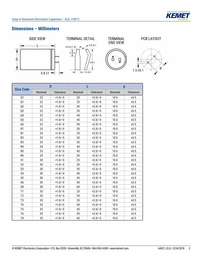
Dimensions – Millimeters
L
SIDE VIEW TERMINALEND VIEW
D
3 ±0.5
0.8 ±0.1
5.8±1
1.5 ±0.1
0.8 ±0.1
5.8 ±1
TERMINAL DETAIL PCB LAYOUT
P1.5 ±0.1
Size CodeD L p
Nominal Tolerance Nominal Tolerance Nominal Tolerance
Q7 22 +1.0/−0 20 +2.0/−0 10.0 ±0.5Q1 22 +1.0/−0 25 +2.0/−0 10.0 ±0.5Q2 22 +1.0/−0 30 +2.0/−0 10.0 ±0.5Q3 22 +1.0/−0 35 +2.0/−0 10.0 ±0.5Q4 22 +1.0/−0 40 +2.0/−0 10.0 ±0.5Q5 22 +1.0/−0 45 +2.0/−0 10.0 ±0.5Q6 22 +1.0/−0 50 +2.0/−0 10.0 ±0.5R7 25 +1.0/−0 20 +2.0/−0 10.0 ±0.5R1 25 +1.0/−0 25 +2.0/−0 10.0 ±0.5R2 25 +1.0/−0 30 +2.0/−0 10.0 ±0.5R3 25 +1.0/−0 35 +2.0/−0 10.0 ±0.5R4 25 +1.0/−0 40 +2.0/−0 10.0 ±0.5R5 25 +1.0/−0 45 +2.0/−0 10.0 ±0.5R6 25 +1.0/−0 50 +2.0/−0 10.0 ±0.5S1 30 +1.0/−0 25 +2.0/−0 10.0 ±0.5S2 30 +1.0/−0 30 +2.0/−0 10.0 ±0.5S3 30 +1.0/−0 35 +2.0/−0 10.0 ±0.5S4 30 +1.0/−0 40 +2.0/−0 10.0 ±0.5S5 30 +1.0/−0 45 +2.0/−0 10.0 ±0.5S6 30 +1.0/−0 50 +2.0/−0 10.0 ±0.5S8 30 +1.0/−0 60 +2.0/−0 10.0 ±0.5T1 35 +1.0/−0 25 +2.0/−0 10.0 ±0.5T2 35 +1.0/−0 30 +2.0/−0 10.0 ±0.5T3 35 +1.0/−0 35 +2.0/−0 10.0 ±0.5T4 35 +1.0/−0 40 +2.0/−0 10.0 ±0.5T5 35 +1.0/−0 45 +2.0/−0 10.0 ±0.5T6 35 +1.0/−0 50 +2.0/−0 10.0 ±0.5T8 35 +1.0/−0 60 +2.0/−0 10.0 ±0.5
3© KEMET Electronics Corporation • P.O. Box 5928 • Greenville, SC 29606 • 864-963-6300 • www.kemet.com A4021_ELG • 5/24/2018
Snap-In Aluminum Electrolytic Capacitors – ELG, +105°C
Environmental Compliance
As an environmentally conscious company, KEMET is working continuously with improvements concerning the environmental effects of both our capacitors and their production. In Europe (RoHS Directive) and in some other geographical areas like China, legislation has been put in place to prevent the use of some hazardous materials, such as lead (Pb), in electronic equipment. All products in this catalog are produced to help our customers’ obligations to guarantee their products and fulfill these legislative requirements. The only material of concern in our products has been lead (Pb), which has been removed from all designs to fulfill the requirement of containing less than 0.1% of lead in any homogeneous material. KEMET will closely follow any changes in legislation world wide and make any necessary changes in its products, whenever needed.
Some customer segments such as medical, military and automotive electronics may still require the use of lead in electrode coatings. To clarify the situation and distinguish products from each other, a special symbol is used on the packaging labels for RoHS compatible capacitors.
Due to customer requirements, there may appear additional markings such as lead free (LF) or lead-free wires (LFW) on the label.
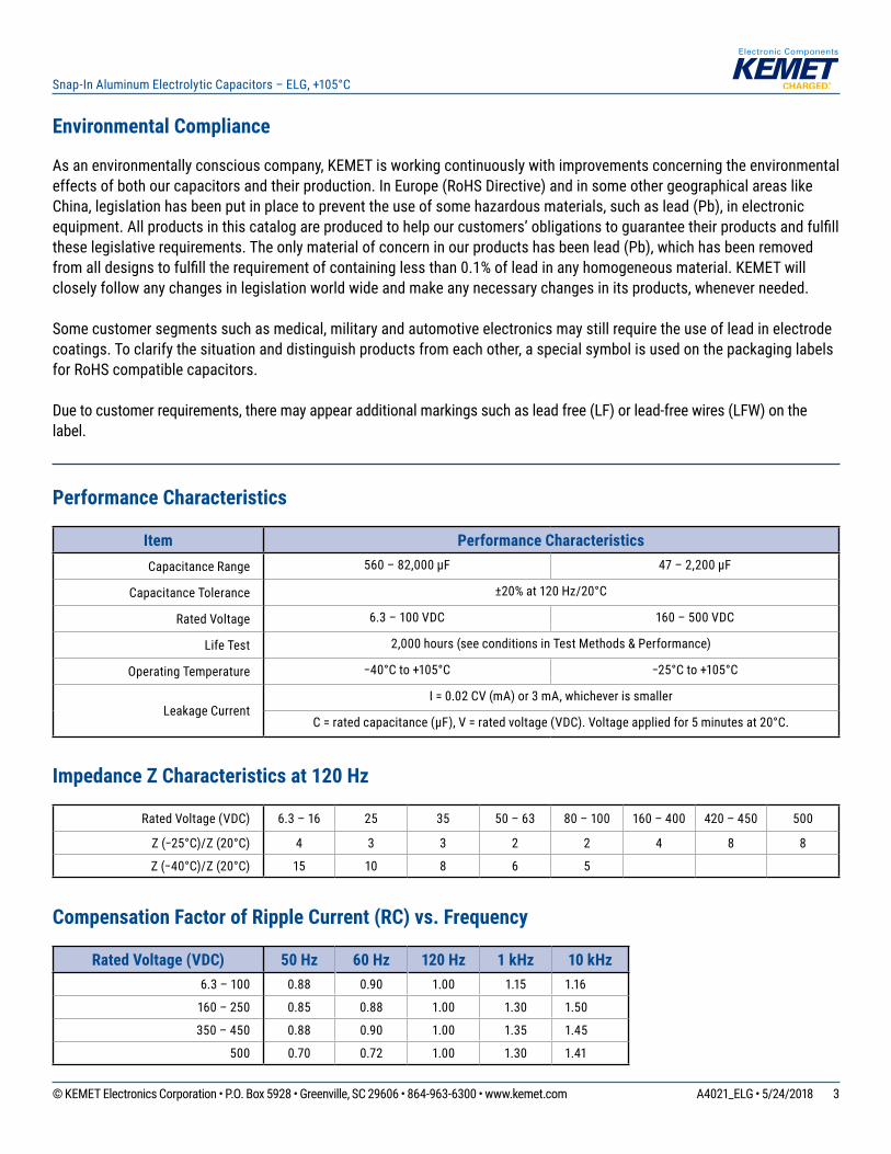
Performance Characteristics
Item Performance CharacteristicsCapacitance Range 560 – 82,000 µF 47 – 2,200 µF
Capacitance Tolerance ±20% at 120 Hz/20°C
Rated Voltage 6.3 – 100 VDC 160 – 500 VDC
Life Test 2,000 hours (see conditions in Test Methods & Performance)
Operating Temperature −40°C to +105°C −25°C to +105°C
Leakage CurrentI = 0.02 CV (mA) or 3 mA, whichever is smaller
C = rated capacitance (µF), V = rated voltage (VDC). Voltage applied for 5 minutes at 20°C.
Impedance Z Characteristics at 120 Hz
Rated Voltage (VDC) 6.3 – 16 25 35 50 – 63 80 – 100 160 – 400 420 – 450 500
Z (−25°C)/Z (20°C) 4 3 3 2 2 4 8 8
Z (−40°C)/Z (20°C) 15 10 8 6 5
Compensation Factor of Ripple Current (RC) vs. Frequency
Rated Voltage (VDC) 50 Hz 60 Hz 120 Hz 1 kHz 10 kHz6.3 – 100 0.88 0.90 1.00 1.15 1.16
160 – 250 0.85 0.88 1.00 1.30 1.50
350 – 450 0.88 0.90 1.00 1.35 1.45
500 0.70 0.72 1.00 1.30 1.41
4© KEMET Electronics Corporation • P.O. Box 5928 • Greenville, SC 29606 • 864-963-6300 • www.kemet.com A4021_ELG • 5/24/2018
Snap-In Aluminum Electrolytic Capacitors – ELG, +105°C
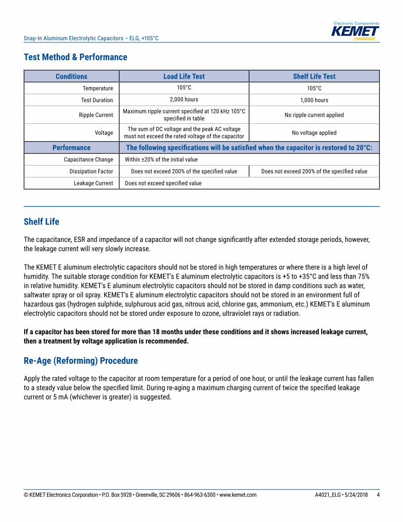
Test Method & Performance
Conditions Load Life Test Shelf Life TestTemperature 105°C 105°C
Test Duration 2,000 hours 1,000 hours
Ripple Current Maximum ripple current specified at 120 kHz 105°C specified in table No ripple current applied
Voltage The sum of DC voltage and the peak AC voltage must not exceed the rated voltage of the capacitor No voltage applied
Performance The following specifications will be satisfied when the capacitor is restored to 20°C:Capacitance Change Within ±20% of the initial value
Dissipation Factor Does not exceed 200% of the specified value Does not exceed 200% of the specified value
Leakage Current Does not exceed specified value
Shelf Life
The capacitance, ESR and impedance of a capacitor will not change significantly after extended storage periods, however, the leakage current will very slowly increase.
The KEMET E aluminum electrolytic capacitors should not be stored in high temperatures or where there is a high level of humidity. The suitable storage condition for KEMET's E aluminum electrolytic capacitors is +5 to +35°C and less than 75% in relative humidity. KEMET's E aluminum electrolytic capacitors should not be stored in damp conditions such as water, saltwater spray or oil spray. KEMET's E aluminum electrolytic capacitors should not be stored in an environment full of hazardous gas (hydrogen sulphide, sulphurous acid gas, nitrous acid, chlorine gas, ammonium, etc.) KEMET's E aluminum electrolytic capacitors should not be stored under exposure to ozone, ultraviolet rays or radiation.
If a capacitor has been stored for more than 18 months under these conditions and it shows increased leakage current, then a treatment by voltage application is recommended.
Re-Age (Reforming) Procedure
Apply the rated voltage to the capacitor at room temperature for a period of one hour, or until the leakage current has fallen to a steady value below the specified limit. During re-aging a maximum charging current of twice the specified leakage current or 5 mA (whichever is greater) is suggested.
5© KEMET Electronics Corporation • P.O. Box 5928 • Greenville, SC 29606 • 864-963-6300 • www.kemet.com A4021_ELG • 5/24/2018
Snap-In Aluminum Electrolytic Capacitors – ELG, +105°C
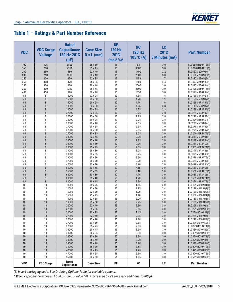
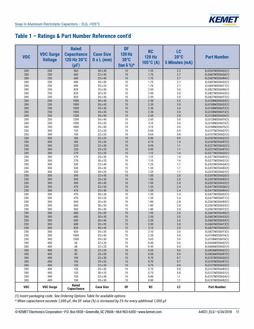
Table 1 – Ratings & Part Number Reference
(1) Insert packaging code. See Ordering Options Table for available options.* When capacitance exceeds 1,000 µF, the DF value (%) is increased by 2% for every additional 1,000 µF.
VDC VDC Surge Voltage
Rated Capacitance 120 Hz 20°C
(µF)
Case Size D x L (mm)
DF 120 Hz 20°C
(tan δ %)*
RC120 Hz
105°C (A)
LC 20°C
5 Minutes (mA)Part Number
100 125 6800 35 x 50 15 3.9 3.0 ELG688M100AT6(1)160 200 2200 35 x 45 15 3300 3.0 ELG228M160AT5(1)200 250 560 22 x 40 15 1400 2.2 ELG567M200AQ4(1)200 250 1200 30 x 40 15 2300 3.0 ELG128M200AS5(1)250 300 330 22 x 35 15 1150 1.7 ELG337M250AQ3(1)250 300 470 25 x 35 15 1500 2.4 ELG477M250AR3(1)250 300 820 30 x 40 15 2000 3.0 ELG827M250AS4(1)250 300 1200 35 x 45 15 2800 3.0 ELG128M250AT5(1)400 450 390 30 x 40 15 1350 3.0 ELG397M400AS4(1)6.3 8 12000 22 x 25 60 1.55 1.5 ELG129M6R3AQ1(1)6.3 8 15000 22 x 30 60 1.70 1.9 ELG159M6R3AQ2(1)6.3 8 15000 25 x 25 60 1.70 1.9 ELG159M6R3AR1(1)6.3 8 18000 22 x 30 60 1.95 2.3 ELG189M6R3AQ2(1)6.3 8 18000 25 x 25 60 1.95 2.3 ELG189M6R3AR1(1)6.3 8 22000 22 x 35 60 2.25 2.8 ELG229M6R3AQ3(1)6.3 8 22000 25 x 30 60 2.25 2.8 ELG229M6R3AR2(1)6.3 8 22000 30 x 25 60 2.25 2.8 ELG229M6R3AS1(1)6.3 8 27000 22 x 40 60 2.55 3.0 ELG279M6R3AQ4(1)6.3 8 27000 25 x 35 60 2.55 3.0 ELG279M6R3AR3(1)6.3 8 27000 30 x 30 60 2.55 3.0 ELG279M6R3AS2(1)6.3 8 27000 35 x 25 60 2.55 3.0 ELG279M6R3AT1(1)6.3 8 33000 22 x 45 60 2.90 3.0 ELG339M6R3AQ5(1)6.3 8 33000 25 x 40 60 2.95 3.0 ELG339M6R3AR4(1)6.3 8 33000 30 x 30 60 2.90 3.0 ELG339M6R3AS2(1)6.3 8 33000 35 x 25 60 2.95 3.0 ELG339M6R3AT1(1)6.3 8 39000 25 x 50 60 3.25 3.0 ELG399M6R3AR6(1)6.3 8 39000 30 x 35 60 3.25 3.0 ELG399M6R3AS3(1)6.3 8 39000 35 x 30 60 3.30 3.0 ELG399M6R3AT2(1)6.3 8 47000 25 x 50 60 3.70 3.0 ELG479M6R3AR6(1)6.3 8 47000 30 x 40 60 3.70 3.0 ELG479M6R3AS4(1)6.3 8 56000 30 x 45 60 4.15 3.0 ELG569M6R3AS5(1)6.3 8 56000 35 x 35 60 4.10 3.0 ELG569M6R3AT3(1)6.3 8 68000 30 x 50 60 4.70 3.0 ELG689M6R3AS6(1)6.3 8 68000 35 x 40 60 4.70 3.0 ELG689M6R3AT4(1)6.3 8 82000 35 x 45 60 5.30 3.0 ELG829M6R3AT5(1)10 13 10000 25 x 25 55 1.55 2.0 ELG109M010AR1(1)10 13 12000 22 x 30 55 1.75 2.4 ELG129M010AQ2(1)10 13 15000 22 x 30 55 1.90 3.0 ELG159M010AQ2(1)10 13 15000 25 x 25 55 1.90 3.0 ELG159M010AR1(1)10 13 18000 22 x 35 55 2.20 3.0 ELG189M010AQ3(1)10 13 18000 25 x 30 55 2.25 3.0 ELG189M010AR2(1)10 13 22000 22 x 40 55 2.50 3.0 ELG229M010AQ4(1)10 13 22000 25 x 35 55 2.55 3.0 ELG229M010AR3(1)10 13 22000 30 x 25 55 2.45 3.0 ELG229M010AS1(1)10 13 27000 22 x 50 55 2.95 3.0 ELG279M010AQ6(1)10 13 27000 25 x 40 55 2.90 3.0 ELG279M010AR4(1)10 13 27000 30 x 30 55 2.85 3.0 ELG279M010AS2(1)10 13 27000 35 x 25 55 2.80 3.0 ELG279M010AT1(1)10 13 33000 25 x 45 55 3.30 3.0 ELG339M010AR5(1)10 13 33000 30 x 35 55 3.30 3.0 ELG339M010AS3(1)10 13 33000 35 x 30 55 3.30 3.0 ELG339M010AT2(1)10 13 39000 25 x 50 55 3.70 3.0 ELG399M010AR6(1)10 13 39000 30 x 40 55 3.70 3.0 ELG399M010AS4(1)10 13 39000 35 x 30 55 3.65 3.0 ELG399M010AT2(1)10 13 47000 30 x 45 55 4.20 3.0 ELG479M010AS5(1)10 13 47000 35 x 35 55 3.80 3.0 ELG479M010AT3(1)10 13 56000 30 x 50 55 4.65 3.0 ELG569M010AS6(1)
VDC VDC Surge RatedCapacitance Case Size DF RC LC Part Number

6© KEMET Electronics Corporation • P.O. Box 5928 • Greenville, SC 29606 • 864-963-6300 • www.kemet.com A4021_ELG • 5/24/2018
Snap-In Aluminum Electrolytic Capacitors – ELG, +105°C
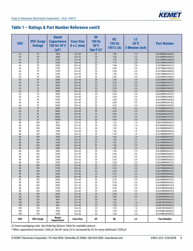
Table 1 – Ratings & Part Number Reference cont'd
(1) Insert packaging code. See Ordering Options Table for available options.* When capacitance exceeds 1,000 µF, the DF value (%) is increased by 2% for every additional 1,000 µF.
VDC VDC Surge Voltage
Rated Capacitance 120 Hz 20°C
(µF)
Case Size D x L (mm)
DF 120 Hz 20°C
(tan δ %)*
RC120 Hz
105°C (A)
LC 20°C
5 Minutes (mA)Part Number
10 13 56000 35 x 40 55 4.65 3.0 ELG569M010AT4(1)10 13 68000 35 x 50 55 5.50 3.0 ELG689M010AT6(1)16 20 6800 22 x 25 55 1.55 2.2 ELG688M016AQ1(1)16 20 8200 22 x 30 55 1.70 2.6 ELG828M016AQ2(1)16 20 8200 25 x 25 55 1.70 2.6 ELG828M016AR1(1)16 20 10000 22 x 30 55 1.95 3.0 ELG109M016AQ2(1)16 20 10000 25 x 25 55 1.95 3.0 ELG109M016AR1(1)16 20 12000 22 x 35 55 2.20 3.0 ELG129M016AQ3(1)16 20 12000 25 x 30 55 2.25 3.0 ELG129M016AR2(1)16 20 12000 30 x 25 55 2.30 3.0 ELG129M016AS1(1)16 20 15000 22 x 40 55 2.55 3.0 ELG159M016AQ4(1)16 20 15000 25 x 35 55 2.60 3.0 ELG159M016AR3(1)16 20 15000 30 x 30 55 2.60 3.0 ELG159M016AS2(1)16 20 15000 35 x 25 55 2.65 3.0 ELG159M016AT1(1)16 20 18000 22 x 45 55 2.90 3.0 ELG189M016AQ5(1)16 20 18000 25 x 40 55 2.90 3.0 ELG189M016AR4(1)16 20 18000 30 x 30 55 2.90 3.0 ELG189M016AS2(1)16 20 18000 35 x 25 55 2.95 3.0 ELG189M016AT1(1)16 20 22000 25 x 45 55 3.30 3.0 ELG229M016AR5(1)16 20 22000 30 x 35 55 3.30 3.0 ELG229M016AS3(1)16 20 22000 35 x 30 55 3.30 3.0 ELG229M016AT2(1)16 20 27000 25 x 50 55 3.80 3.0 ELG279M016AR6(1)16 20 27000 30 x 40 55 3.75 3.0 ELG279M016AS4(1)16 20 27000 35 x 30 55 3.75 3.0 ELG279M016AT2(1)16 20 33000 30 x 45 55 4.30 3.0 ELG339M016AS5(1)16 20 33000 35 x 35 55 4.25 3.0 ELG339M016AT3(1)16 20 39000 30 x 50 55 4.80 3.0 ELG399M016AS6(1)16 20 39000 35 x 40 55 4.80 3.0 ELG399M016AT4(1)16 20 47000 35 x 45 55 5.45 3.0 ELG479M016AT5(1)16 20 56000 35 x 45 55 5.65 3.0 ELG569M016AT5(1)16 20 68000 35 x 50 55 6.20 3.0 ELG689M016AT6(1)25 32 4700 22 x 25 45 1.50 2.4 ELG478M025AQ1(1)25 32 5600 22 x 30 45 1.65 2.8 ELG568M025AQ2(1)25 32 5600 25 x 25 45 1.65 2.8 ELG568M025AR1(1)25 32 6800 22 x 30 45 1.85 3.0 ELG688M025AQ2(1)25 32 6800 25 x 25 45 1.85 3.0 ELG688M025AR1(1)25 32 8200 22 x 35 45 2.10 3.0 ELG828M025AQ3(1)25 32 8200 25 x 30 45 2.10 3.0 ELG828M025AR2(1)25 32 8200 30 x 25 45 2.15 3.0 ELG828M025AS1(1)25 32 10000 22 x 40 45 2.40 3.0 ELG109M025AQ4(1)25 32 10000 25 x 35 45 2.40 3.0 ELG109M025AR3(1)25 32 10000 30 x 30 45 2.40 3.0 ELG109M025AS2(1)25 32 10000 35 x 25 45 2.40 3.0 ELG109M025AT1(1)25 32 12000 22 x 45 45 2.70 3.0 ELG129M025AQ5(1)25 32 12000 25 x 40 45 2.75 3.0 ELG129M025AR4(1)25 32 12000 30 x 30 45 2.70 3.0 ELG129M025AS2(1)25 32 12000 35 x 25 45 2.75 3.0 ELG129M025AT1(1)25 32 15000 25 x 45 45 3.15 3.0 ELG159M025AR5(1)25 32 15000 30 x 35 45 3.15 3.0 ELG159M025AS3(1)25 32 15000 35 x 30 45 3.25 3.0 ELG159M025AT2(1)25 32 18000 25 x 50 45 3.55 3.0 ELG189M025AR6(1)25 32 18000 30 x 40 45 3.55 3.0 ELG189M025AS4(1)25 32 18000 35 x 35 45 3.55 3.0 ELG189M025AT3(1)25 32 22000 30 x 45 45 4.05 3.0 ELG229M025AS5(1)25 32 22000 35 x 35 45 3.80 3.0 ELG229M025AT3(1)25 32 27000 35 x 45 45 4.70 3.0 ELG279M025AT5(1)25 32 33000 35 x 50 45 5.40 3.0 ELG339M025AT6(1)
VDC VDC Surge RatedCapacitance Case Size DF RC LC Part Number

7© KEMET Electronics Corporation • P.O. Box 5928 • Greenville, SC 29606 • 864-963-6300 • www.kemet.com A4021_ELG • 5/24/2018
Snap-In Aluminum Electrolytic Capacitors – ELG, +105°C
VDC VDC Surge Voltage
Rated Capacitance 120 Hz 20°C
(µF)
Case Size D x L (mm)
DF 120 Hz 20°C
(tan δ %)*
RC120 Hz
105°C (A)
LC 20°C
5 Minutes (mA)Part Number
25 32 39000 35 x 45 45 5.50 3.0 ELG399M025AT5(1)25 32 47000 35 x 50 45 6.00 3.0 ELG479M025AT6(1)35 44 3300 22 x 25 35 1.40 2.3 ELG338M035AQ1(1)35 44 3900 22 x 30 35 1.55 2.7 ELG398M035AQ2(1)35 44 3900 25 x 25 35 1.55 2.7 ELG398M035AR1(1)35 44 4700 22 x 35 35 1.80 3.0 ELG478M035AQ3(1)35 44 4700 25 x 25 35 1.80 3.0 ELG478M035AR1(1)35 44 5600 22 x 35 35 1.95 3.0 ELG568M035AQ3(1)35 44 5600 25 x 30 35 1.95 3.0 ELG568M035AR2(1)35 44 5600 30 x 25 35 2.00 3.0 ELG568M035AS1(1)35 44 6800 22 x 40 35 2.20 3.0 ELG688M035AQ4(1)35 44 6800 25 x 35 35 2.25 3.0 ELG688M035AR3(1)35 44 6800 30 x 30 35 2.30 3.0 ELG688M035AS2(1)35 44 6800 35 x 25 35 2.35 3.0 ELG688M035AT1(1)35 44 8200 22 x 50 35 2.55 3.0 ELG828M035AQ6(1)35 44 8200 25 x 40 35 2.50 3.0 ELG828M035AR4(1)35 44 8200 30 x 30 35 2.75 3.0 ELG828M035AS2(1)35 44 8200 35 x 25 35 2.75 3.0 ELG828M035AT1(1)35 44 10000 25 x 45 35 2.85 3.0 ELG109M035AR5(1)35 44 10000 30 x 35 35 2.90 3.0 ELG109M035AS3(1)35 44 10000 35 x 30 35 2.95 3.0 ELG109M035AT2(1)35 44 12000 25 x 50 35 3.25 3.0 ELG129M035AR6(1)35 44 12000 30 x 40 35 3.25 3.0 ELG129M035AS4(1)35 44 12000 35 x 30 35 3.15 3.0 ELG129M035AT2(1)35 44 15000 30 x 45 35 3.70 3.0 ELG159M035AS5(1)35 44 15000 35 x 35 35 3.65 3.0 ELG159M035AT3(1)35 44 18000 35 x 40 35 4.35 3.0 ELG189M035AT4(1)35 44 22000 30 x 50 35 4.90 3.0 ELG229M035AS6(1)50 63 1800 22 x 25 30 1.30 1.8 ELG188M050AQ1(1)50 63 2200 22 x 30 30 1.55 2.2 ELG228M050AQ2(1)50 63 2200 25 x 25 30 1.55 2.2 ELG228M050AR1(1)50 63 2700 22 x 30 30 1.70 2.7 ELG278M050AQ2(1)50 63 2700 25 x 25 30 1.70 2.7 ELG278M050AR1(1)50 63 3300 22 x 35 30 1.95 3.0 ELG338M050AQ3(1)50 63 3300 25 x 30 30 1.85 3.0 ELG338M050AR2(1)50 63 3900 22 x 40 30 2.15 3.0 ELG398M050AQ4(1)50 63 3900 25 x 35 30 2.20 3.0 ELG398M050AR3(1)50 63 3900 30 x 25 30 1.95 3.0 ELG398M050AS1(1)50 63 4700 22 x 45 30 2.45 3.0 ELG478M050AQ5(1)50 63 4700 25 x 40 30 2.45 3.0 ELG478M050AR4(1)50 63 4700 30 x 30 30 2.45 3.0 ELG478M050AS2(1)50 63 4700 35 x 25 30 2.50 3.0 ELG478M050AT1(1)50 63 5600 22 x 50 30 2.75 3.0 ELG568M050AQ6(1)50 63 5600 25 x 40 30 2.70 3.0 ELG568M050AR4(1)50 63 5600 30 x 35 30 2.75 3.0 ELG568M050AS3(1)50 63 5600 35 x 30 30 2.75 3.0 ELG568M050AT2(1)50 63 6800 25 x 50 30 3.30 3.0 ELG688M050AR6(1)50 63 6800 30 x 40 30 3.30 3.0 ELG688M050AS4(1)50 63 6800 35 x 30 30 3.25 3.0 ELG688M050AT2(1)50 63 8200 30 x 45 30 3.60 3.0 ELG828M050AS5(1)50 63 8200 35 x 35 30 3.55 3.0 ELG828M050AT3(1)50 63 10000 30 x 50 30 4.05 3.0 ELG109M050AS6(1)50 63 10000 35 x 40 30 4.00 3.0 ELG109M050AT4(1)50 63 12000 35 x 45 30 4.55 3.0 ELG129M050AT5(1)63 79 1200 22 x 25 25 1.20 1.5 ELG128M063AQ1(1)63 79 1500 22 x 30 25 1.30 1.9 ELG158M063AQ2(1)63 79 1500 25 x 25 25 1.30 1.9 ELG158M063AR1(1)
VDC VDC Surge RatedCapacitance Case Size DF RC LC Part Number
Table 1 – Ratings & Part Number Reference cont'd
(1) Insert packaging code. See Ordering Options Table for available options.* When capacitance exceeds 1,000 µF, the DF value (%) is increased by 2% for every additional 1,000 µF.
8© KEMET Electronics Corporation • P.O. Box 5928 • Greenville, SC 29606 • 864-963-6300 • www.kemet.com A4021_ELG • 5/24/2018
Snap-In Aluminum Electrolytic Capacitors – ELG, +105°C
VDC VDC Surge Voltage
Rated Capacitance 120 Hz 20°C
(µF)
Case Size D x L (mm)
DF 120 Hz 20°C
(tan δ %)*
RC120 Hz
105°C (A)
LC 20°C
5 Minutes (mA)Part Number
63 79 1800 22 x 30 25 1.50 2.3 ELG188M063AQ2(1)63 79 1800 25 x 25 25 1.50 2.3 ELG188M063AR1(1)63 79 2200 22 x 35 25 1.70 2.8 ELG228M063AQ3(1)63 79 2200 25 x 30 25 1.75 2.8 ELG228M063AR2(1)63 79 2200 30 x 25 25 1.80 2.8 ELG228M063AS1(1)63 79 2700 22 x 40 25 2.00 3.0 ELG278M063AQ4(1)63 79 2700 25 x 35 25 2.00 3.0 ELG278M063AR3(1)63 79 2700 30 x 25 25 1.95 3.0 ELG278M063AS1(1)63 79 3300 22 x 50 25 2.30 3.0 ELG338M063AQ6(1)63 79 3300 25 x 40 25 2.30 3.0 ELG338M063AR4(1)63 79 3300 30 x 30 25 2.25 3.0 ELG338M063AS2(1)63 79 3300 35 x 25 25 2.10 3.0 ELG338M063AT1(1)63 79 3900 25 x 45 25 2.55 3.0 ELG398M063AR5(1)63 79 3900 30 x 35 25 2.55 3.0 ELG398M063AS3(1)63 79 3900 35 x 30 25 2.55 3.0 ELG398M063AT2(1)63 79 4700 25 x 50 25 2.85 3.0 ELG478M063AR6(1)63 79 4700 30 x 40 25 2.85 3.0 ELG478M063AS4(1)63 79 4700 35 x 30 25 2.80 3.0 ELG478M063AT2(1)63 79 5600 30 x 45 25 3.20 3.0 ELG568M063AS5(1)63 79 5600 35 x 35 25 3.20 3.0 ELG568M063AT3(1)63 79 6800 30 x 50 25 3.65 3.0 ELG688M063AS6(1)63 79 6800 35 x 40 25 3.65 3.0 ELG688M063AT4(1)63 79 8200 35 x 45 25 3.90 3.0 ELG828M063AT5(1)63 79 10000 35 x 50 25 4.40 3.0 ELG109M063AT6(1)80 100 820 22 x 25 25 1.10 1.3 ELG827M080AQ1(1)80 100 1000 22 x 30 25 1.20 1.6 ELG108M080AQ2(1)80 100 1000 25 x 25 25 1.20 1.6 ELG108M080AR1(1)80 100 1200 22 x 30 25 1.40 1.9 ELG128M080AQ2(1)80 100 1200 25 x 25 25 1.40 1.9 ELG128M080AR1(1)80 100 1500 22 x 35 25 1.60 2.4 ELG158M080AQ3(1)80 100 1500 25 x 30 25 1.60 2.4 ELG158M080AR2(1)80 100 1500 30 x 25 25 1.65 2.4 ELG158M080AS1(1)80 100 1800 22 x 40 25 1.80 2.9 ELG188M080AQ4(1)80 100 1800 25 x 35 25 1.85 2.9 ELG188M080AR3(1)80 100 1800 30 x 25 25 1.80 2.9 ELG188M080AS1(1)80 100 2200 22 x 45 25 2.05 3.0 ELG228M080AQ5(1)80 100 2200 25 x 35 25 2.00 3.0 ELG228M080AR3(1)80 100 2200 30 x 30 25 2.05 3.0 ELG228M080AS2(1)80 100 2200 35 x 25 25 2.05 3.0 ELG228M080AT1(1)80 100 2700 25 x 45 25 2.35 3.0 ELG278M080AR5(1)80 100 2700 30 x 35 25 2.35 3.0 ELG278M080AS3(1)80 100 2700 35 x 30 25 2.35 3.0 ELG278M080AT2(1)80 100 3300 25 x 50 25 2.70 3.0 ELG338M080AR6(1)80 100 3300 30 x 40 25 2.70 3.0 ELG338M080AS4(1)80 100 3300 35 x 30 25 2.55 3.0 ELG338M080AT2(1)80 100 3900 30 x 45 25 3.00 3.0 ELG398M080AS5(1)80 100 3900 35 x 35 25 3.00 3.0 ELG398M080AT3(1)80 100 4700 30 x 50 25 3.40 3.0 ELG478M080AS6(1)80 100 4700 35 x 40 25 3.40 3.0 ELG478M080AT4(1)80 100 5600 35 x 45 25 3.80 3.0 ELG568M080AT5(1)80 100 6800 35 x 50 25 3.90 3.0 ELG688M080AT6(1)
100 125 560 22 x 25 25 1.05 1.1 ELG567M100AQ1(1)100 125 680 22 x 25 25 1.20 1.4 ELG687M100AQ1(1)100 125 820 22 x 30 25 1.30 1.6 ELG827M100AQ2(1)100 125 820 25 x 25 25 1.33 1.6 ELG827M100AR1(1)100 125 1000 22 x 35 25 1.50 2.0 ELG108M100AQ3(1)100 125 1000 25 x 30 25 1.50 2.0 ELG108M100AR2(1)
VDC VDC Surge RatedCapacitance Case Size DF RC LC Part Number
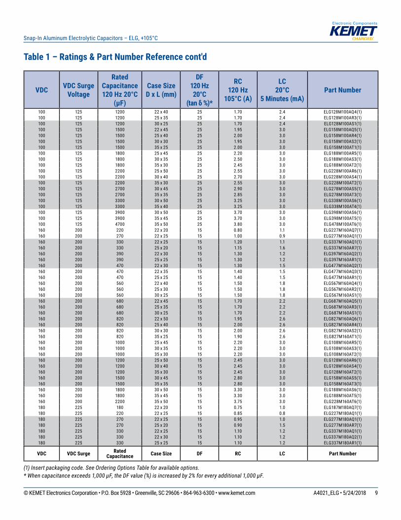
Table 1 – Ratings & Part Number Reference cont'd
(1) Insert packaging code. See Ordering Options Table for available options.* When capacitance exceeds 1,000 µF, the DF value (%) is increased by 2% for every additional 1,000 µF.
9© KEMET Electronics Corporation • P.O. Box 5928 • Greenville, SC 29606 • 864-963-6300 • www.kemet.com A4021_ELG • 5/24/2018
Snap-In Aluminum Electrolytic Capacitors – ELG, +105°C
VDC VDC Surge Voltage
Rated Capacitance 120 Hz 20°C
(µF)
Case Size D x L (mm)
DF 120 Hz 20°C
(tan δ %)*
RC120 Hz
105°C (A)
LC 20°C
5 Minutes (mA)Part Number
100 125 1200 22 x 40 25 1.70 2.4 ELG128M100AQ4(1)100 125 1200 25 x 35 25 1.70 2.4 ELG128M100AR3(1)100 125 1200 30 x 25 25 1.70 2.4 ELG128M100AS1(1)100 125 1500 22 x 45 25 1.95 3.0 ELG158M100AQ5(1)100 125 1500 25 x 40 25 2.00 3.0 ELG158M100AR4(1)100 125 1500 30 x 30 25 1.95 3.0 ELG158M100AS2(1)100 125 1500 35 x 25 25 2.00 3.0 ELG158M100AT1(1)100 125 1800 25 x 45 25 2.20 3.0 ELG188M100AR5(1)100 125 1800 30 x 35 25 2.50 3.0 ELG188M100AS3(1)100 125 1800 35 x 30 25 2.45 3.0 ELG188M100AT2(1)100 125 2200 25 x 50 25 2.55 3.0 ELG228M100AR6(1)100 125 2200 30 x 40 25 2.70 3.0 ELG228M100AS4(1)100 125 2200 35 x 30 25 2.55 3.0 ELG228M100AT2(1)100 125 2700 30 x 45 25 2.90 3.0 ELG278M100AS5(1)100 125 2700 35 x 35 25 2.85 3.0 ELG278M100AT3(1)100 125 3300 30 x 50 25 3.25 3.0 ELG338M100AS6(1)100 125 3300 35 x 40 25 3.25 3.0 ELG338M100AT4(1)100 125 3900 30 x 50 25 3.70 3.0 ELG398M100AS6(1)100 125 3900 35 x 45 25 3.70 3.0 ELG398M100AT5(1)100 125 4700 35 x 50 25 3.80 3.0 ELG478M100AT6(1)160 200 220 22 x 20 15 0.80 1.1 ELG227M160AQ7(1)160 200 270 22 x 25 15 1.00 0.9 ELG277M160AQ1(1)160 200 330 22 x 25 15 1.20 1.1 ELG337M160AQ1(1)160 200 330 25 x 20 15 1.15 1.6 ELG337M160AR7(1)160 200 390 22 x 30 15 1.30 1.2 ELG397M160AQ2(1)160 200 390 25 x 25 15 1.30 1.2 ELG397M160AR1(1)160 200 470 22 x 30 15 1.30 1.5 ELG477M160AQ2(1)160 200 470 22 x 35 15 1.40 1.5 ELG477M160AQ3(1)160 200 470 25 x 25 15 1.40 1.5 ELG477M160AR1(1)160 200 560 22 x 40 15 1.50 1.8 ELG567M160AQ4(1)160 200 560 25 x 30 15 1.50 1.8 ELG567M160AR2(1)160 200 560 30 x 25 15 1.50 1.8 ELG567M160AS1(1)160 200 680 22 x 45 15 1.70 2.2 ELG687M160AQ5(1)160 200 680 25 x 35 15 1.70 2.2 ELG687M160AR3(1)160 200 680 30 x 25 15 1.70 2.2 ELG687M160AS1(1)160 200 820 22 x 50 15 1.95 2.6 ELG827M160AQ6(1)160 200 820 25 x 40 15 2.00 2.6 ELG827M160AR4(1)160 200 820 30 x 30 15 2.00 2.6 ELG827M160AS2(1)160 200 820 35 x 25 15 1.90 2.6 ELG827M160AT1(1)160 200 1000 25 x 45 15 2.20 3.0 ELG108M160AR5(1)160 200 1000 30 x 35 15 2.20 3.0 ELG108M160AS3(1)160 200 1000 35 x 30 15 2.20 3.0 ELG108M160AT2(1)160 200 1200 25 x 50 15 2.45 3.0 ELG128M160AR6(1)160 200 1200 30 x 40 15 2.45 3.0 ELG128M160AS4(1)160 200 1200 35 x 30 15 2.45 3.0 ELG128M160AT2(1)160 200 1500 30 x 45 15 2.80 3.0 ELG158M160AS5(1)160 200 1500 35 x 35 15 2.80 3.0 ELG158M160AT3(1)160 200 1800 30 x 50 15 3.30 3.0 ELG188M160AS6(1)160 200 1800 35 x 45 15 3.30 3.0 ELG188M160AT5(1)160 200 2200 35 x 50 15 3.75 3.0 ELG228M160AT6(1)180 225 180 22 x 20 15 0.75 1.0 ELG187M180AQ7(1)180 225 220 22 x 25 15 0.85 0.8 ELG227M180AQ1(1)180 225 270 22 x 25 15 0.95 1.0 ELG277M180AQ1(1)180 225 270 25 x 20 15 0.90 1.5 ELG277M180AR7(1)180 225 330 22 x 25 15 1.10 1.2 ELG337M180AQ1(1)180 225 330 22 x 30 15 1.10 1.2 ELG337M180AQ2(1)180 225 330 25 x 25 15 1.10 1.2 ELG337M180AR1(1)
VDC VDC Surge RatedCapacitance Case Size DF RC LC Part Number
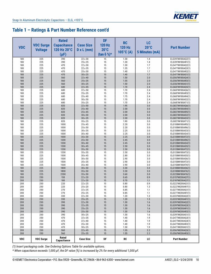
Table 1 – Ratings & Part Number Reference cont'd
(1) Insert packaging code. See Ordering Options Table for available options.* When capacitance exceeds 1,000 µF, the DF value (%) is increased by 2% for every additional 1,000 µF.
10© KEMET Electronics Corporation • P.O. Box 5928 • Greenville, SC 29606 • 864-963-6300 • www.kemet.com A4021_ELG • 5/24/2018
Snap-In Aluminum Electrolytic Capacitors – ELG, +105°C
VDC VDC Surge Voltage
Rated Capacitance 120 Hz 20°C
(µF)
Case Size D x L (mm)
DF 120 Hz 20°C
(tan δ %)*
RC120 Hz
105°C (A)
LC 20°C
5 Minutes (mA)Part Number
180 225 390 22 x 30 15 1.30 1.4 ELG397M180AQ2(1)180 225 390 25 x 25 15 1.30 1.4 ELG397M180AR1(1)180 225 470 22 x 30 15 1.30 1.7 ELG477M180AQ2(1)180 225 470 22 x 35 15 1.35 1.7 ELG477M180AQ3(1)180 225 470 25 x 30 15 1.40 1.7 ELG477M180AR2(1)180 225 470 30 x 25 15 1.40 1.7 ELG477M180AS1(1)180 225 560 22 x 40 15 1.50 2.0 ELG567M180AQ4(1)180 225 560 25 x 35 15 1.55 2.0 ELG567M180AR3(1)180 225 560 30 x 25 15 1.50 2.0 ELG567M180AS1(1)180 225 680 22 x 45 15 1.70 2.4 ELG687M180AQ5(1)180 225 680 22 x 50 15 1.70 2.4 ELG687M180AQ6(1)180 225 680 25 x 35 15 1.70 2.4 ELG687M180AR3(1)180 225 680 25 x 40 15 1.75 2.4 ELG687M180AR4(1)180 225 680 30 x 30 15 1.70 2.4 ELG687M180AS2(1)180 225 680 35 x 25 15 1.70 2.4 ELG687M180AT1(1)180 225 820 22 x 50 15 1.95 3.0 ELG827M180AQ6(1)180 225 820 25 x 40 15 2.00 3.0 ELG827M180AR4(1)180 225 820 25 x 45 15 2.00 3.0 ELG827M180AR5(1)180 225 820 30 x 30 15 2.00 3.0 ELG827M180AS2(1)180 225 820 30 x 35 15 2.00 3.0 ELG827M180AS3(1)180 225 820 35 x 25 15 1.90 3.0 ELG827M180AT1(1)180 225 1000 25 x 45 15 2.20 3.0 ELG108M180AR5(1)180 225 1000 25 x 50 15 2.20 3.0 ELG108M180AR6(1)180 225 1000 30 x 35 15 2.25 3.0 ELG108M180AS3(1)180 225 1000 30 x 40 15 2.25 3.0 ELG108M180AS4(1)180 225 1000 35 x 30 15 2.25 3.0 ELG108M180AT2(1)180 225 1200 25 x 50 15 2.45 3.0 ELG128M180AR6(1)180 225 1200 30 x 40 15 2.45 3.0 ELG128M180AS4(1)180 225 1200 30 x 45 15 2.50 3.0 ELG128M180AS5(1)180 225 1200 35 x 30 15 2.50 3.0 ELG128M180AT2(1)180 225 1200 35 x 35 15 2.50 3.0 ELG128M180AT3(1)180 225 1500 30 x 45 15 2.80 3.0 ELG158M180AS5(1)180 225 1500 30 x 50 15 2.90 3.0 ELG158M180AS6(1)180 225 1500 35 x 35 15 2.90 3.0 ELG158M180AT3(1)180 225 1500 35 x 40 15 2.90 3.0 ELG158M180AT4(1)180 225 1800 30 x 50 15 3.30 3.0 ELG188M180AS6(1)180 225 1800 35 x 50 15 3.30 3.0 ELG188M180AT6(1)180 225 2200 35 x 50 15 3.60 3.0 ELG228M180AT6(1)200 250 150 22 x 20 15 0.65 0.9 ELG157M200AQ7(1)200 250 180 22 x 20 15 0.70 1.1 ELG187M200AQ7(1)200 250 220 22 x 25 15 0.80 0.9 ELG227M200AQ1(1)200 250 220 25 x 20 15 0.80 1.3 ELG227M200AR7(1)200 250 270 22 x 25 15 0.85 1.1 ELG277M200AQ1(1)200 250 270 25 x 25 15 0.85 1.1 ELG277M200AR1(1)200 250 330 22 x 30 15 1.20 1.3 ELG337M200AQ2(1)200 250 330 25 x 25 15 1.20 1.3 ELG337M200AR1(1)200 250 390 22 x 30 15 1.30 1.6 ELG397M200AQ2(1)200 250 390 22 x 35 15 1.30 1.6 ELG397M200AQ3(1)200 250 390 25 x 25 15 1.30 1.6 ELG397M200AR1(1)200 250 390 25 x 30 15 1.30 1.6 ELG397M200AR2(1)200 250 390 30 x 25 15 1.30 1.6 ELG397M200AS1(1)200 250 470 22 x 35 15 1.40 1.9 ELG477M200AQ3(1)200 250 470 22 x 40 15 1.40 1.9 ELG477M200AQ4(1)200 250 470 25 x 30 15 1.40 1.9 ELG477M200AR2(1)200 250 470 30 x 25 15 1.50 1.9 ELG477M200AS1(1)200 250 560 22 x 45 15 1.55 2.2 ELG567M200AQ5(1)200 250 560 25 x 35 15 1.55 2.2 ELG567M200AR3(1)
VDC VDC Surge RatedCapacitance Case Size DF RC LC Part Number
Table 1 – Ratings & Part Number Reference cont'd
(1) Insert packaging code. See Ordering Options Table for available options.* When capacitance exceeds 1,000 µF, the DF value (%) is increased by 2% for every additional 1,000 µF.
11© KEMET Electronics Corporation • P.O. Box 5928 • Greenville, SC 29606 • 864-963-6300 • www.kemet.com A4021_ELG • 5/24/2018
Snap-In Aluminum Electrolytic Capacitors – ELG, +105°C
VDC VDC Surge Voltage
Rated Capacitance 120 Hz 20°C
(µF)
Case Size D x L (mm)
DF 120 Hz 20°C
(tan δ %)*
RC120 Hz
105°C (A)
LC 20°C
5 Minutes (mA)Part Number
200 250 560 30 x 30 15 1.55 2.2 ELG567M200AS2(1)200 250 680 22 x 50 15 1.75 2.7 ELG687M200AQ6(1)200 250 680 25 x 40 15 1.75 2.7 ELG687M200AR4(1)200 250 680 30 x 30 15 1.75 2.7 ELG687M200AS2(1)200 250 680 35 x 25 15 1.70 2.7 ELG687M200AT1(1)200 250 820 25 x 50 15 2.05 3.0 ELG827M200AR6(1)200 250 820 30 x 35 15 2.00 3.0 ELG827M200AS3(1)200 250 820 35 x 30 15 2.05 3.0 ELG827M200AT2(1)200 250 1000 30 x 40 15 2.30 3.0 ELG108M200AS4(1)200 250 1000 30 x 45 15 2.30 3.0 ELG108M200AS5(1)200 250 1000 35 x 30 15 2.30 3.0 ELG108M200AT2(1)200 250 1000 35 x 35 15 2.30 3.0 ELG108M200AT3(1)200 250 1200 30 x 50 15 2.60 3.0 ELG128M200AS6(1)200 250 1200 35 x 40 15 2.65 3.0 ELG128M200AT4(1)200 250 1500 35 x 45 15 3.10 3.0 ELG158M200AT5(1)200 250 1800 35 x 50 15 3.15 3.0 ELG188M200AT6(1)250 300 120 22 x 20 15 0.60 0.9 ELG127M250AQ7(1)250 300 150 22 x 25 15 0.65 0.8 ELG157M250AQ1(1)250 300 180 22 x 25 15 0.80 0.9 ELG187M250AQ1(1)250 300 180 25 x 20 15 0.75 1.4 ELG187M250AR7(1)250 300 220 22 x 30 15 0.95 1.1 ELG227M250AQ2(1)250 300 220 25 x 25 15 0.95 1.1 ELG227M250AR1(1)250 300 270 22 x 35 15 1.15 1.4 ELG277M250AQ3(1)250 300 270 25 x 30 15 1.15 1.4 ELG277M250AR2(1)250 300 270 30 x 25 15 1.15 1.4 ELG277M250AS1(1)250 300 330 22 x 40 15 1.25 1.7 ELG337M250AQ4(1)250 300 330 25 x 30 15 1.20 1.7 ELG337M250AR2(1)250 300 330 30 x 25 15 1.25 1.7 ELG337M250AS1(1)250 300 390 22 x 45 15 1.50 2.0 ELG397M250AQ5(1)250 300 390 25 x 35 15 1.50 2.0 ELG397M250AR3(1)250 300 390 30 x 30 15 1.50 2.0 ELG397M250AS2(1)250 300 470 22 x 50 15 1.55 2.4 ELG477M250AQ6(1)250 300 470 25 x 40 15 1.55 2.4 ELG477M250AR4(1)250 300 470 30 x 30 15 1.55 2.4 ELG477M250AS2(1)250 300 470 35 x 25 15 1.55 2.4 ELG477M250AT1(1)250 300 560 25 x 45 15 1.80 2.8 ELG567M250AR5(1)250 300 560 30 x 35 15 1.80 2.8 ELG567M250AS3(1)250 300 560 35 x 30 15 1.80 2.8 ELG567M250AT2(1)250 300 680 25 x 50 15 1.95 3.0 ELG687M250AR6(1)250 300 680 30 x 35 15 2.00 3.0 ELG687M250AS3(1)250 300 680 30 x 40 15 2.00 3.0 ELG687M250AS4(1)250 300 680 35 x 35 15 2.00 3.0 ELG687M250AT3(1)250 300 820 30 x 45 15 2.15 3.0 ELG827M250AS5(1)250 300 820 35 x 35 15 2.10 3.0 ELG827M250AT3(1)250 300 1000 35 x 40 15 2.30 3.0 ELG108M250AT4(1)250 300 1500 35 x 50 15 3.63 3.0 ELG158M250AT6(1)350 400 56 22 x 20 15 0.40 0.6 ELG566M350AQ7(1)350 400 68 22 x 25 15 0.45 0.5 ELG686M350AQ1(1)350 400 82 22 x 25 15 0.55 0.6 ELG826M350AQ1(1)350 400 82 25 x 20 15 0.50 0.9 ELG826M350AR7(1)350 400 100 22 x 30 15 0.70 0.7 ELG107M350AQ2(1)350 400 100 25 x 25 15 0.70 0.7 ELG107M350AR1(1)350 400 120 22 x 35 15 0.75 0.8 ELG127M350AQ3(1)350 400 120 25 x 30 15 0.75 0.8 ELG127M350AR2(1)350 400 120 30 x 25 15 0.75 0.8 ELG127M350AS1(1)350 400 150 22 x 40 15 0.80 1.1 ELG157M350AQ4(1)350 400 150 25 x 30 15 0.80 1.1 ELG157M350AR2(1)
VDC VDC Surge RatedCapacitance Case Size DF RC LC Part Number
Table 1 – Ratings & Part Number Reference cont'd
(1) Insert packaging code. See Ordering Options Table for available options.* When capacitance exceeds 1,000 µF, the DF value (%) is increased by 2% for every additional 1,000 µF.

12© KEMET Electronics Corporation • P.O. Box 5928 • Greenville, SC 29606 • 864-963-6300 • www.kemet.com A4021_ELG • 5/24/2018
Snap-In Aluminum Electrolytic Capacitors – ELG, +105°C
VDC VDC Surge Voltage
Rated Capacitance 120 Hz 20°C
(µF)
Case Size D x L (mm)
DF 120 Hz 20°C
(tan δ %)*
RC120 Hz
105°C (A)
LC 20°C
5 Minutes (mA)Part Number
350 400 150 30 x 25 15 0.85 1.1 ELG157M350AS1(1)350 400 180 22 x 45 15 0.90 1.3 ELG187M350AQ5(1)350 400 180 25 x 35 15 0.90 1.3 ELG187M350AR3(1)350 400 180 30 x 30 15 0.90 1.3 ELG187M350AS2(1)350 400 220 22 x 50 15 1.05 1.5 ELG227M350AQ6(1)350 400 220 25 x 40 15 1.05 1.5 ELG227M350AR4(1)350 400 220 30 x 30 15 1.00 1.5 ELG227M350AS2(1)350 400 220 35 x 25 15 1.05 1.5 ELG227M350AT1(1)350 400 270 25 x 45 15 1.20 1.9 ELG277M350AR5(1)350 400 270 30 x 35 15 1.20 1.9 ELG277M350AS3(1)350 400 270 35 x 30 15 1.20 1.9 ELG277M350AT2(1)350 400 330 30 x 40 15 1.35 2.3 ELG337M350AS4(1)350 400 330 35 x 35 15 1.35 2.3 ELG337M350AT3(1)350 400 390 30 x 45 15 1.50 2.7 ELG397M350AS5(1)350 400 390 35 x 35 15 1.50 2.7 ELG397M350AT3(1)350 400 470 35 x 40 15 1.70 3.0 ELG477M350AT4(1)350 400 560 35 x 45 15 1.90 3.0 ELG567M350AT5(1)400 450 47 22 x 20 15 0.35 0.6 ELG476M400AQ7(1)400 450 56 22 x 20 15 0.40 0.7 ELG566M400AQ7(1)400 450 68 22 x 25 15 0.50 0.5 ELG686M400AQ1(1)400 450 68 25 x 20 15 0.50 0.8 ELG686M400AR7(1)400 450 82 22 x 25 15 0.52 0.7 ELG826M400AQ1(1)400 450 82 22 x 30 15 0.60 0.7 ELG826M400AQ2(1)400 450 82 25 x 25 15 0.65 0.7 ELG826M400AR1(1)400 450 100 22 x 30 15 0.60 0.8 ELG107M400AQ2(1)400 450 100 22 x 35 15 0.65 0.8 ELG107M400AQ3(1)400 450 100 25 x 30 15 0.65 0.8 ELG107M400AR2(1)400 450 120 22 x 30 15 0.62 1.0 ELG127M400AQ2(1)400 450 120 22 x 35 15 0.70 1.0 ELG127M400AQ3(1)400 450 120 25 x 30 15 0.70 1.0 ELG127M400AR2(1)400 450 120 30 x 25 15 0.75 1.0 ELG127M400AS1(1)400 450 150 22 x 35 15 0.72 1.2 ELG157M400AQ3(1)400 450 150 22 x 40 15 0.80 1.2 ELG157M400AQ4(1)400 450 150 25 x 30 15 0.85 1.2 ELG157M400AR2(1)400 450 150 25 x 35 15 0.85 1.2 ELG157M400AR3(1)400 450 150 30 x 30 15 0.85 1.2 ELG157M400AS2(1)400 450 150 35 x 25 15 0.80 1.2 ELG157M400AT1(1)400 450 180 22 x 40 15 0.81 1.4 ELG187M400AQ4(1)400 450 180 22 x 50 15 0.95 1.4 ELG187M400AQ6(1)400 450 180 25 x 40 15 0.95 1.4 ELG187M400AR4(1)400 450 180 30 x 30 15 0.90 1.4 ELG187M400AS2(1)400 450 220 25 x 45 15 1.05 1.8 ELG227M400AR5(1)400 450 220 30 x 35 15 1.05 1.8 ELG227M400AS3(1)400 450 220 35 x 30 15 1.10 1.8 ELG227M400AT2(1)400 450 270 25 x 45 15 1.10 2.2 ELG277M400AR5(1)400 450 270 25 x 50 15 1.20 2.2 ELG277M400AR6(1)400 450 270 30 x 40 15 1.20 2.2 ELG277M400AS4(1)400 450 270 35 x 35 15 1.20 2.2 ELG277M400AT3(1)400 450 330 25 x 50 15 1.25 2.6 ELG337M400AR6(1)400 450 330 30 x 45 15 1.40 2.6 ELG337M400AS5(1)400 450 330 35 x 35 15 1.35 2.6 ELG337M400AT3(1)400 450 390 30 x 45 15 1.42 3.0 ELG397M400AS5(1)400 450 390 30 x 50 15 1.55 3.0 ELG397M400AS6(1)400 450 390 35 x 40 15 1.55 3.0 ELG397M400AT4(1)400 450 470 30 x 45 15 1.45 3.0 ELG477M400AS5(1)400 450 470 30 x 50 15 1.75 3.0 ELG477M400AS6(1)400 450 470 35 x 40 15 1.65 3.0 ELG477M400AT4(1)
VDC VDC Surge RatedCapacitance Case Size DF RC LC Part Number
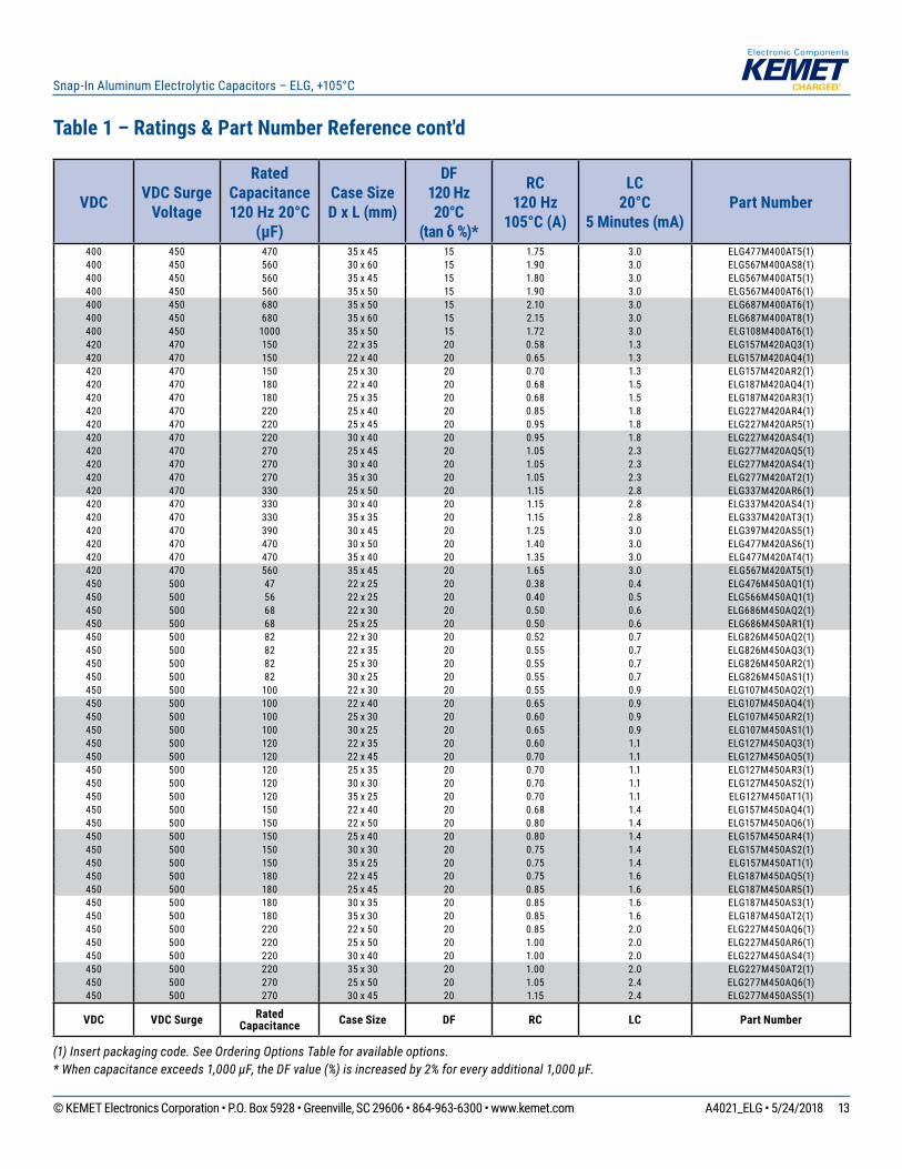
Table 1 – Ratings & Part Number Reference cont'd
(1) Insert packaging code. See Ordering Options Table for available options.* When capacitance exceeds 1,000 µF, the DF value (%) is increased by 2% for every additional 1,000 µF.
13© KEMET Electronics Corporation • P.O. Box 5928 • Greenville, SC 29606 • 864-963-6300 • www.kemet.com A4021_ELG • 5/24/2018
Snap-In Aluminum Electrolytic Capacitors – ELG, +105°C
VDC VDC Surge Voltage
Rated Capacitance 120 Hz 20°C
(µF)
Case Size D x L (mm)
DF 120 Hz 20°C
(tan δ %)*
RC120 Hz
105°C (A)
LC 20°C
5 Minutes (mA)Part Number
400 450 470 35 x 45 15 1.75 3.0 ELG477M400AT5(1)400 450 560 30 x 60 15 1.90 3.0 ELG567M400AS8(1)400 450 560 35 x 45 15 1.80 3.0 ELG567M400AT5(1)400 450 560 35 x 50 15 1.90 3.0 ELG567M400AT6(1)400 450 680 35 x 50 15 2.10 3.0 ELG687M400AT6(1)400 450 680 35 x 60 15 2.15 3.0 ELG687M400AT8(1)400 450 1000 35 x 50 15 1.72 3.0 ELG108M400AT6(1)420 470 150 22 x 35 20 0.58 1.3 ELG157M420AQ3(1)420 470 150 22 x 40 20 0.65 1.3 ELG157M420AQ4(1)420 470 150 25 x 30 20 0.70 1.3 ELG157M420AR2(1)420 470 180 22 x 40 20 0.68 1.5 ELG187M420AQ4(1)420 470 180 25 x 35 20 0.68 1.5 ELG187M420AR3(1)420 470 220 25 x 40 20 0.85 1.8 ELG227M420AR4(1)420 470 220 25 x 45 20 0.95 1.8 ELG227M420AR5(1)420 470 220 30 x 40 20 0.95 1.8 ELG227M420AS4(1)420 470 270 25 x 45 20 1.05 2.3 ELG277M420AQ5(1)420 470 270 30 x 40 20 1.05 2.3 ELG277M420AS4(1)420 470 270 35 x 30 20 1.05 2.3 ELG277M420AT2(1)420 470 330 25 x 50 20 1.15 2.8 ELG337M420AR6(1)420 470 330 30 x 40 20 1.15 2.8 ELG337M420AS4(1)420 470 330 35 x 35 20 1.15 2.8 ELG337M420AT3(1)420 470 390 30 x 45 20 1.25 3.0 ELG397M420AS5(1)420 470 470 30 x 50 20 1.40 3.0 ELG477M420AS6(1)420 470 470 35 x 40 20 1.35 3.0 ELG477M420AT4(1)420 470 560 35 x 45 20 1.65 3.0 ELG567M420AT5(1)450 500 47 22 x 25 20 0.38 0.4 ELG476M450AQ1(1)450 500 56 22 x 25 20 0.40 0.5 ELG566M450AQ1(1)450 500 68 22 x 30 20 0.50 0.6 ELG686M450AQ2(1)450 500 68 25 x 25 20 0.50 0.6 ELG686M450AR1(1)450 500 82 22 x 30 20 0.52 0.7 ELG826M450AQ2(1)450 500 82 22 x 35 20 0.55 0.7 ELG826M450AQ3(1)450 500 82 25 x 30 20 0.55 0.7 ELG826M450AR2(1)450 500 82 30 x 25 20 0.55 0.7 ELG826M450AS1(1)450 500 100 22 x 30 20 0.55 0.9 ELG107M450AQ2(1)450 500 100 22 x 40 20 0.65 0.9 ELG107M450AQ4(1)450 500 100 25 x 30 20 0.60 0.9 ELG107M450AR2(1)450 500 100 30 x 25 20 0.65 0.9 ELG107M450AS1(1)450 500 120 22 x 35 20 0.60 1.1 ELG127M450AQ3(1)450 500 120 22 x 45 20 0.70 1.1 ELG127M450AQ5(1)450 500 120 25 x 35 20 0.70 1.1 ELG127M450AR3(1)450 500 120 30 x 30 20 0.70 1.1 ELG127M450AS2(1)450 500 120 35 x 25 20 0.70 1.1 ELG127M450AT1(1)450 500 150 22 x 40 20 0.68 1.4 ELG157M450AQ4(1)450 500 150 22 x 50 20 0.80 1.4 ELG157M450AQ6(1)450 500 150 25 x 40 20 0.80 1.4 ELG157M450AR4(1)450 500 150 30 x 30 20 0.75 1.4 ELG157M450AS2(1)450 500 150 35 x 25 20 0.75 1.4 ELG157M450AT1(1)450 500 180 22 x 45 20 0.75 1.6 ELG187M450AQ5(1)450 500 180 25 x 45 20 0.85 1.6 ELG187M450AR5(1)450 500 180 30 x 35 20 0.85 1.6 ELG187M450AS3(1)450 500 180 35 x 30 20 0.85 1.6 ELG187M450AT2(1)450 500 220 22 x 50 20 0.85 2.0 ELG227M450AQ6(1)450 500 220 25 x 50 20 1.00 2.0 ELG227M450AR6(1)450 500 220 30 x 40 20 1.00 2.0 ELG227M450AS4(1)450 500 220 35 x 30 20 1.00 2.0 ELG227M450AT2(1)450 500 270 25 x 50 20 1.05 2.4 ELG277M450AQ6(1)450 500 270 30 x 45 20 1.15 2.4 ELG277M450AS5(1)
VDC VDC Surge RatedCapacitance Case Size DF RC LC Part Number
Table 1 – Ratings & Part Number Reference cont'd
(1) Insert packaging code. See Ordering Options Table for available options.* When capacitance exceeds 1,000 µF, the DF value (%) is increased by 2% for every additional 1,000 µF.
14© KEMET Electronics Corporation • P.O. Box 5928 • Greenville, SC 29606 • 864-963-6300 • www.kemet.com A4021_ELG • 5/24/2018
Snap-In Aluminum Electrolytic Capacitors – ELG, +105°C
VDC VDC Surge Voltage
Rated Capacitance 120 Hz 20°C
(µF)
Case Size D x L (mm)
DF 120 Hz 20°C
(tan δ %)*
RC120 Hz
105°C (A)
LC 20°C
5 Minutes (mA)Part Number
450 500 270 35 x 35 20 1.15 2.4 ELG277M450AT3(1)450 500 330 30 x 45 20 1.25 3.0 ELG337M450AS5(1)450 500 330 30 x 50 20 1.40 3.0 ELG337M450AS6(1)450 500 330 35 x 40 20 1.40 3.0 ELG337M450AT4(1)450 500 390 30 x 50 20 1.40 3.0 ELG397M450AS6(1)450 500 390 35 x 45 20 1.55 3.0 ELG397M450AT5(1)450 500 470 35 x 45 20 1.68 3.0 ELG477M450AT5(1)450 500 470 35 x 50 20 1.70 3.0 ELG477M450AT6(1)450 500 560 35 x 50 20 1.80 3.0 ELG567M450AT6(1)450 500 560 35 x 60 20 2.10 3.0 ELG567M450AT8(1)500 550 47 22 x 25 25 0.51 0.5 ELG476M500AQ1(1)500 550 56 22 x 30 25 0.58 0.6 ELG566M500AQ2(1)500 550 68 25 x 25 25 0.65 0.7 ELG686M500AR1(1)500 550 82 22 x 35 25 0.72 0.8 ELG826M500AQ3(1)500 550 82 25 x 30 25 0.74 0.8 ELG826M500AR2(1)500 550 100 22 x 45 25 0.83 1.0 ELG107M500AQ5(1)500 550 100 30 x 25 25 0.82 1.0 ELG107M500AS1(1)500 550 120 22 x 50 25 0.93 1.2 ELG127M500AQ6(1)500 550 120 25 x 35 25 0.93 1.2 ELG127M500AR3(1)500 550 120 30 x 30 25 0.91 1.2 ELG127M500AS2(1)500 550 150 30 x 35 25 1.04 1.5 ELG157M500AS3(1)500 550 150 25 x 45 25 1.08 1.5 ELG157M500AS5(1)500 550 150 35 x 25 25 0.99 1.5 ELG157M500AT1(1)500 550 180 25 x 50 25 1.20 1.8 ELG187M500AR6(1)500 550 180 30 x 40 25 1.17 1.8 ELG187M500AS4(1)500 550 180 35 x 30 25 1.10 1.8 ELG187M500AT2(1)500 550 220 30 x 45 25 1.33 2.2 ELG227M500AS5(1)500 550 220 35 x 35 25 1.23 2.2 ELG227M500AT3(1)500 550 270 30 x 50 25 1.50 2.7 ELG277M500AS6(1)500 550 270 35 x 40 25 1.42 2.7 ELG277M500AT4(1)500 550 330 35 x 45 25 1.60 3.0 ELG337M500AT5(1)500 550 390 35 x 50 25 1.78 3.0 ELG337M500AT6(1)500 550 470 35 x 60 25 2.03 3.0 ELG477M500AT8(1)
VDC VDC Surge RatedCapacitance Case Size DF RC LC Part Number
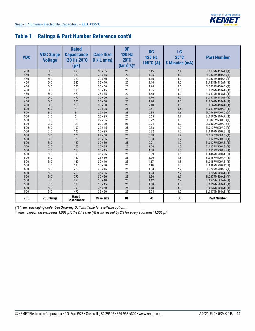
Table 1 – Ratings & Part Number Reference cont'd
(1) Insert packaging code. See Ordering Options Table for available options.* When capacitance exceeds 1,000 µF, the DF value (%) is increased by 2% for every additional 1,000 µF.
15© KEMET Electronics Corporation • P.O. Box 5928 • Greenville, SC 29606 • 864-963-6300 • www.kemet.com A4021_ELG • 5/24/2018
Snap-In Aluminum Electrolytic Capacitors – ELG, +105°C
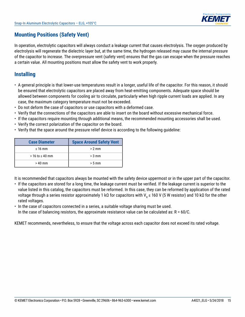
Mounting Positions (Safety Vent)
In operation, electrolytic capacitors will always conduct a leakage current that causes electrolysis. The oxygen produced by electrolysis will regenerate the dielectric layer but, at the same time, the hydrogen released may cause the internal pressure of the capacitor to increase. The overpressure vent (safety vent) ensures that the gas can escape when the pressure reaches a certain value. All mounting positions must allow the safety vent to work properly.
Installing
• A general principle is that lower-use temperatures result in a longer, useful life of the capacitor. For this reason, it should be ensured that electrolytic capacitors are placed away from heat-emitting components. Adequate space should be allowed between components for cooling air to circulate, particularly when high ripple current loads are applied. In any case, the maximum category temperature must not be exceeded.
• Do not deform the case of capacitors or use capacitors with a deformed case.• Verify that the connections of the capacitors are able to insert on the board without excessive mechanical force.• If the capacitors require mounting through additional means, the recommended mounting accessories shall be used.• Verify the correct polarization of the capacitor on the board.• Verify that the space around the pressure relief device is according to the following guideline:
Case Diameter Space Around Safety Vent≤ 16 mm > 2 mm
> 16 to ≤ 40 mm > 3 mm
> 40 mm > 5 mm
It is recommended that capacitors always be mounted with the safety device uppermost or in the upper part of the capacitor. • If the capacitors are stored for a long time, the leakage current must be verifi ed. If the leakage current is superior to the
value listed in this catalog, the capacitors must be reformed. In this case, they can be reformed by application of the rated voltage through a series resistor approximately 1 kΩ for capacitors with VR ≤ 160 V (5 W resistor) and 10 kΩ for the other rated voltages.
• In the case of capacitors connected in a series, a suitable voltage sharing must be used.In the case of balancing resistors, the approximate resistance value can be calculated as: R = 60/C.
KEMET recommends, nevertheless, to ensure that the voltage across each capacitor does not exceed its rated voltage.
16© KEMET Electronics Corporation • P.O. Box 5928 • Greenville, SC 29606 • 864-963-6300 • www.kemet.com A4021_ELG • 5/24/2018
Snap-In Aluminum Electrolytic Capacitors – ELG, +105°C
Application and Operation Guidelines
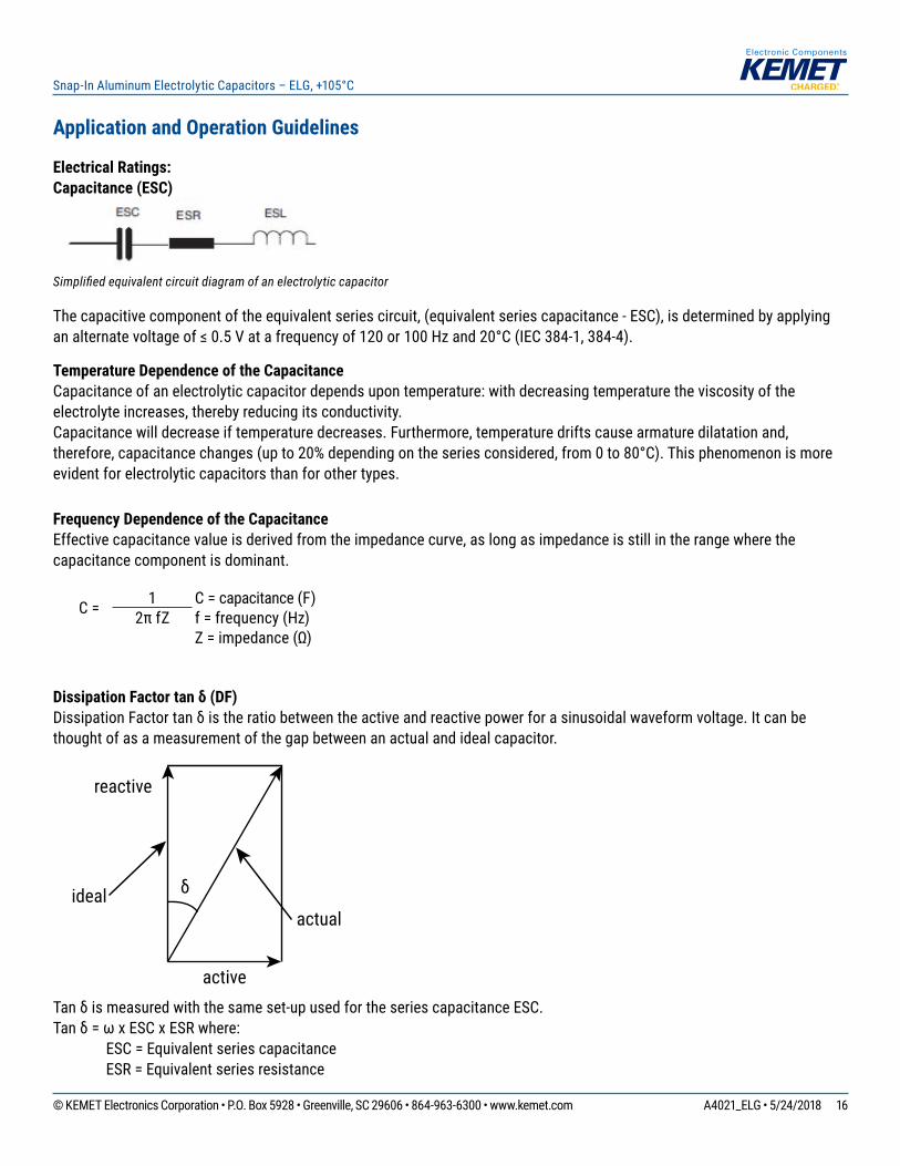
Electrical Ratings:Capacitance (ESC)
Simplifi ed equivalent circuit diagram of an electrolytic capacitor
The capacitive component of the equivalent series circuit, (equivalent series capacitance - ESC), is determined by applying an alternate voltage of ≤ 0.5 V at a frequency of 120 or 100 Hz and 20°C (IEC 384-1, 384-4).
Temperature Dependence of the CapacitanceCapacitance of an electrolytic capacitor depends upon temperature: with decreasing temperature the viscosity of the electrolyte increases, thereby reducing its conductivity.Capacitance will decrease if temperature decreases. Furthermore, temperature drifts cause armature dilatation and, therefore, capacitance changes (up to 20% depending on the series considered, from 0 to 80°C). This phenomenon is more evident for electrolytic capacitors than for other types.
Frequency Dependence of the Capacitance Effective capacitance value is derived from the impedance curve, as long as impedance is still in the range where the capacitance component is dominant.
C = 1 C = capacitance (F)2π fZ f = frequency (Hz)
Z = impedance (Ω)
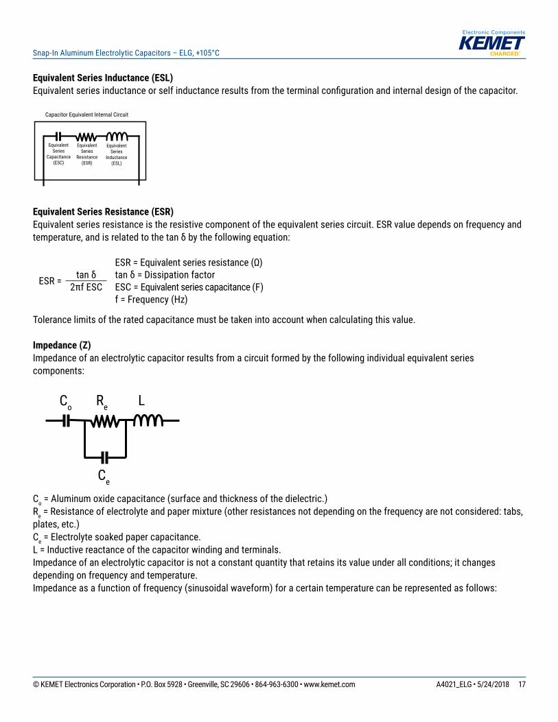
Dissipation Factor tan δ (DF)Dissipation Factor tan δ is the ratio between the active and reactive power for a sinusoidal waveform voltage. It can be thought of as a measurement of the gap between an actual and ideal capacitor.
reactive
active
idealactual
δ
Tan δ is measured with the same set-up used for the series capacitance ESC.Tan δ = ω x ESC x ESR where: ESC = Equivalent series capacitance ESR = Equivalent series resistance
17© KEMET Electronics Corporation • P.O. Box 5928 • Greenville, SC 29606 • 864-963-6300 • www.kemet.com A4021_ELG • 5/24/2018
Snap-In Aluminum Electrolytic Capacitors – ELG, +105°C
Equivalent Series Inductance (ESL)Equivalent series inductance or self inductance results from the terminal confi guration and internal design of the capacitor.
EquivalentSeries
Capacitance(ESC)
EquivalentSeries
Resistance(ESR)
EquivalentSeries
Inductance(ESL)
Capacitor Equivalent Internal Circuit
Equivalent Series Resistance (ESR) Equivalent series resistance is the resistive component of the equivalent series circuit. ESR value depends on frequency and temperature, and is related to the tan δ by the following equation:
ESR = Equivalent series resistance (Ω)
ESR = tan δ tan δ = Dissipation factor2πf ESC ESC = Equivalent series capacitance (F)
f = Frequency (Hz)
Tolerance limits of the rated capacitance must be taken into account when calculating this value.
Impedance (Z)Impedance of an electrolytic capacitor results from a circuit formed by the following individual equivalent series components:
Equivalent
Capacitance
C o R e L
C e
Co Re L
Ce
Co = Aluminum oxide capacitance (surface and thickness of the dielectric.)Re = Resistance of electrolyte and paper mixture (other resistances not depending on the frequency are not considered: tabs, plates, etc.)Ce = Electrolyte soaked paper capacitance. L = Inductive reactance of the capacitor winding and terminals. Impedance of an electrolytic capacitor is not a constant quantity that retains its value under all conditions; it changes depending on frequency and temperature.Impedance as a function of frequency (sinusoidal waveform) for a certain temperature can be represented as follows:
18© KEMET Electronics Corporation • P.O. Box 5928 • Greenville, SC 29606 • 864-963-6300 • www.kemet.com A4021_ELG • 5/24/2018
Snap-In Aluminum Electrolytic Capacitors – ELG, +105°C
Impedance (Z) cont’d
�
C o R e L
C e
0.1 1 10 100 1,000 10,0000.1
1
10
100
1,000
Z [ohm ]
F [K Hz]
B
C
A
1/ωωωω C o
R e
1/ωωωω C e
ωL
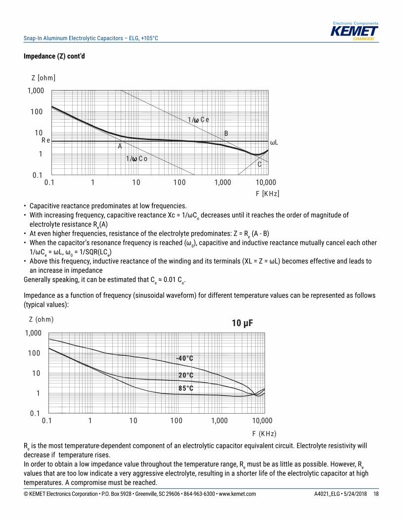
• Capacitive reactance predominates at low frequencies.• With increasing frequency, capacitive reactance Xc = 1/ωCo decreases until it reaches the order of magnitude of
electrolyte resistance Re(A)• At even higher frequencies, resistance of the electrolyte predominates: Z = Re (A - B)• When the capacitor’s resonance frequency is reached (ω0), capacitive and inductive reactance mutually cancel each other
1/ωCe = ωL, ω0 = 1/SQR(LCe)• Above this frequency, inductive reactance of the winding and its terminals (XL = Z = ωL) becomes effective and leads to
an increase in impedanceGenerally speaking, it can be estimated that Ce ≈ 0.01 Co.
Impedance as a function of frequency (sinusoidal waveform) for different temperature values can be represented as follows (typical values):
0.1 1 10 100 1,000 10,0000.1
1
10
100
1,000
Z (ohm)
F (K Hz)
85°C
20°C
10 µF
-40°C
Re is the most temperature-dependent component of an electrolytic capacitor equivalent circuit. Electrolyte resistivity will decrease if temperature rises.In order to obtain a low impedance value throughout the temperature range, Re must be as little as possible. However, Re values that are too low indicate a very aggressive electrolyte, resulting in a shorter life of the electrolytic capacitor at high temperatures. A compromise must be reached.
19© KEMET Electronics Corporation • P.O. Box 5928 • Greenville, SC 29606 • 864-963-6300 • www.kemet.com A4021_ELG • 5/24/2018
Snap-In Aluminum Electrolytic Capacitors – ELG, +105°C
Leakage Current (LC)Due to the aluminum oxide layer that serves as a dielectric, a small current will continue to fl ow even after a DC voltage has been applied for long periods. This current is called leakage current.
A high leakage current fl ows after applying voltage to the capacitor then decreases in a few minutes, for example, after prolonged storage without any applied voltage. In the course of continuous operation, the leakage current will decrease and reach an almost constant value.
After a voltage-free storage the oxide layer may deteriorate, especially at a high temperature. Since there are no leakage currents to transport oxygen ions to the anode, the oxide layer is not regenerated. The result is that a higher than normal leakage current will fl ow when voltage is applied after prolonged storage.
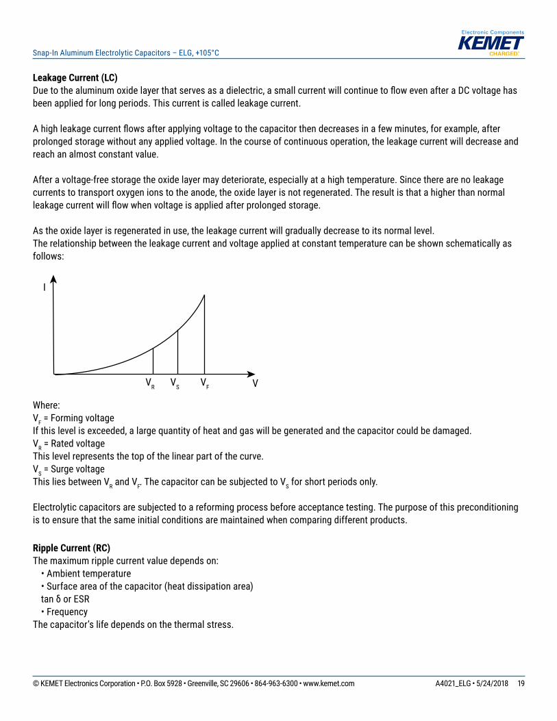
As the oxide layer is regenerated in use, the leakage current will gradually decrease to its normal level.The relationship between the leakage current and voltage applied at constant temperature can be shown schematically as follows:
I
VR VF VVS
Where:VF = Forming voltageIf this level is exceeded, a large quantity of heat and gas will be generated and the capacitor could be damaged.VR = Rated voltageThis level represents the top of the linear part of the curve.VS = Surge voltageThis lies between VR and VF. The capacitor can be subjected to VS for short periods only.
Electrolytic capacitors are subjected to a reforming process before acceptance testing. The purpose of this preconditioning is to ensure that the same initial conditions are maintained when comparing different products.
Ripple Current (RC)The maximum ripple current value depends on: • Ambient temperature • Surface area of the capacitor (heat dissipation area)
tan δ or ESR • FrequencyThe capacitor’s life depends on the thermal stress.
20© KEMET Electronics Corporation • P.O. Box 5928 • Greenville, SC 29606 • 864-963-6300 • www.kemet.com A4021_ELG • 5/24/2018
Snap-In Aluminum Electrolytic Capacitors – ELG, +105°C
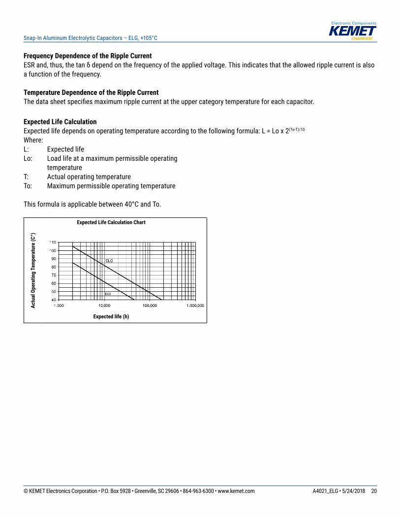
Frequency Dependence of the Ripple Current ESR and, thus, the tan δ depend on the frequency of the applied voltage. This indicates that the allowed ripple current is also a function of the frequency.
Temperature Dependence of the Ripple CurrentThe data sheet specifi es maximum ripple current at the upper category temperature for each capacitor.
Expected Life CalculationExpected life depends on operating temperature according to the following formula: L = Lo x 2(To-T)/10
Where:L: Expected lifeLo: Load life at a maximum permissible operating
temperatureT: Actual operating temperatureTo: Maximum permissible operating temperature
This formula is applicable between 40°C and To.
Actu
al O
pera
ting
Tem
pera
ture
(C°)
Expected Life Calculation Chart
Expected life (h)
21© KEMET Electronics Corporation • P.O. Box 5928 • Greenville, SC 29606 • 864-963-6300 • www.kemet.com A4021_ELG • 5/24/2018
Snap-In Aluminum Electrolytic Capacitors – ELG, +105°C
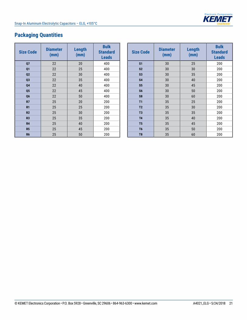
Packaging Quantities
Size Code Diameter (mm)
Length(mm)
BulkStandard
LeadsQ7 22 20 400Q1 22 25 400Q2 22 30 400Q3 22 35 400Q4 22 40 400Q5 22 45 400Q6 22 50 400R7 25 20 200R1 25 25 200R2 25 30 200R3 25 35 200R4 25 40 200R5 25 45 200R6 25 50 200
Size Code Diameter (mm)
Length(mm)
BulkStandard
LeadsS1 30 25 200S2 30 30 200S3 30 35 200S4 30 40 200S5 30 45 200S6 30 50 200S8 30 60 200T1 35 25 200T2 35 30 200T3 35 35 200T4 35 40 200T5 35 45 200T6 35 50 200T8 35 60 200
22© KEMET Electronics Corporation • P.O. Box 5928 • Greenville, SC 29606 • 864-963-6300 • www.kemet.com A4021_ELG • 5/24/2018
Snap-In Aluminum Electrolytic Capacitors – ELG, +105°C
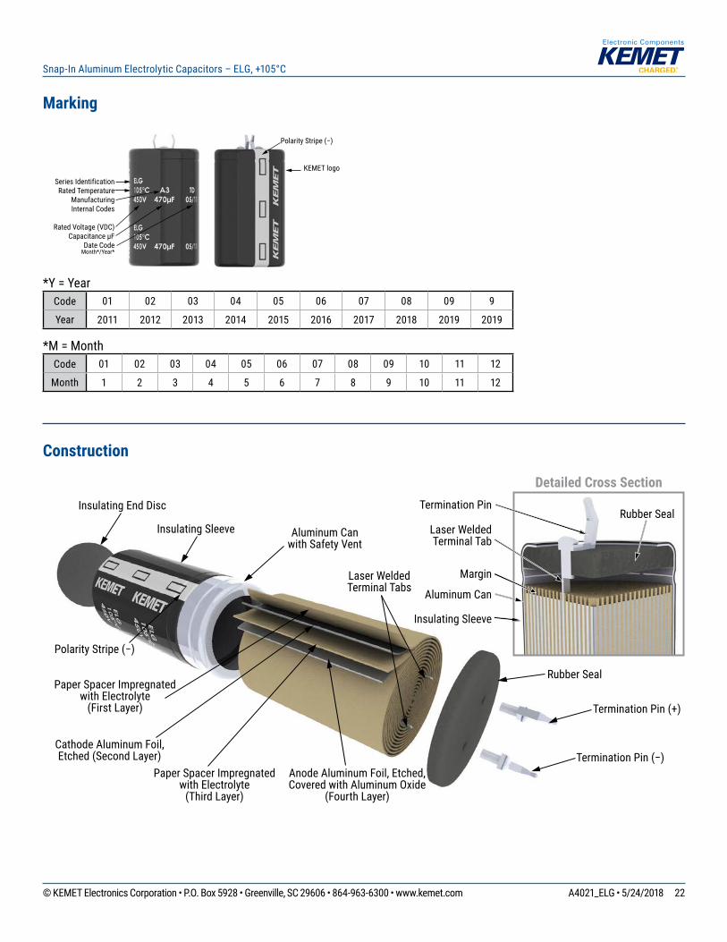
Marking
Series IdentificationRated Temperature
Manufacturing Internal Codes
Rated Voltage (VDC)Capacitance µF
Date Code Month*/Year*
Polarity Stripe (−)
KEMET logo
*Y = YearCode 01 02 03 04 05 06 07 08 09 9
Year 2011 2012 2013 2014 2015 2016 2017 2018 2019 2019
*M = MonthCode 01 02 03 04 05 06 07 08 09 10 11 12
Month 1 2 3 4 5 6 7 8 9 10 11 12
Construction
Detailed Cross Section
Margin
Termination Pin (+)
Rubber Seal
Rubber Seal
Insulating Sleeve Aluminum Can with Safety Vent
Laser Welded Terminal Tabs
Termination Pin
Laser Welded Terminal Tab
Aluminum Can
Insulating Sleeve
Polarity Stripe (−)
Insulating End Disc
Termination Pin (−)
Paper Spacer Impregnatedwith Electrolyte
(First Layer)
Paper Spacer Impregnated with Electrolyte
(Third Layer)
Anode Aluminum Foil, Etched, Covered with Aluminum Oxide
(Fourth Layer)
Cathode Aluminum Foil, Etched (Second Layer)
23© KEMET Electronics Corporation • P.O. Box 5928 • Greenville, SC 29606 • 864-963-6300 • www.kemet.com A4021_ELG • 5/24/2018
Snap-In Aluminum Electrolytic Capacitors – ELG, +105°C
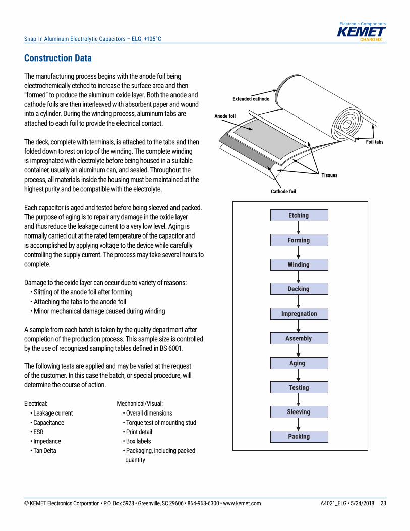
Extended cathode
Anode foil
Cathode foil
Tissues
Foil tabs
Aging
Etching
Forming
Winding
Decking
Impregnation
Assembly
Testing
Sleeving
Packing
Construction Data
The manufacturing process begins with the anode foil being electrochemically etched to increase the surface area and then “formed” to produce the aluminum oxide layer. Both the anode and cathode foils are then interleaved with absorbent paper and wound into a cylinder. During the winding process, aluminum tabs are attached to each foil to provide the electrical contact.
The deck, complete with terminals, is attached to the tabs and then folded down to rest on top of the winding. The complete winding is impregnated with electrolyte before being housed in a suitable container, usually an aluminum can, and sealed. Throughout the process, all materials inside the housing must be maintained at the highest purity and be compatible with the electrolyte.
Each capacitor is aged and tested before being sleeved and packed. The purpose of aging is to repair any damage in the oxide layer and thus reduce the leakage current to a very low level. Aging is normally carried out at the rated temperature of the capacitor and is accomplished by applying voltage to the device while carefully controlling the supply current. The process may take several hours to complete.
Damage to the oxide layer can occur due to variety of reasons: • Slitting of the anode foil after forming • Attaching the tabs to the anode foil • Minor mechanical damage caused during winding
A sample from each batch is taken by the quality department after completion of the production process. This sample size is controlled by the use of recognized sampling tables defi ned in BS 6001.
The following tests are applied and may be varied at the request of the customer. In this case the batch, or special procedure, will determine the course of action.
Electrical: • Leakage current • Capacitance • ESR • Impedance • Tan Delta
Mechanical/Visual: • Overall dimensions • Torque test of mounting stud • Print detail • Box labels • Packaging, including packed
quantity
24© KEMET Electronics Corporation • P.O. Box 5928 • Greenville, SC 29606 • 864-963-6300 • www.kemet.com A4021_ELG • 5/24/2018
Snap-In Aluminum Electrolytic Capacitors – ELG, +105°C
KEMET Electronics Corporation Sales Offi ces
For a complete list of our global sales offi ces, please visit www.kemet.com/sales.
DisclaimerAll product specifi cations, statements, information and data (collectively, the “Information”) in this datasheet are subject to change. The customer is responsible for checking and verifying the extent to which the Information contained in this publication is applicable to an order at the time the order is placed.
All Information given herein is believed to be accurate and reliable, but it is presented without guarantee, warranty, or responsibility of any kind, expressed or implied.
Statements of suitability for certain applications are based on KEMET Electronics Corporation’s (“KEMET”) knowledge of typical operating conditions for such applications, but are not intended to constitute – and KEMET specifi cally disclaims – any warranty concerning suitability for a specifi c customer application or use. The Information is intended for use only by customers who have the requisite experience and capability to determine the correct products for their application. Any technical advice inferred from this Information or otherwise provided by KEMET with reference to the use of KEMET’s products is given gratis, and KEMET assumes no obligation or liability for the advice given or results obtained.
Although KEMET designs and manufactures its products to the most stringent quality and safety standards, given the current state of the art, isolated component failures may still occur. Accordingly, customer applications which require a high degree of reliability or safety should employ suitable designs or other safeguards (such as installation of protective circuitry or redundancies) in order to ensure that the failure of an electrical component does not result in a risk of personal injury or property damage.
Although all product–related warnings, cautions and notes must be observed, the customer should not assume that all safety measures are indicted or that other measures may not be required.
KEMET is a registered trademark of KEMET Electronics Corporation.