sm/fex300/fex500/atex/iecex-en processmaster ... · sm/fex300/fex500/atex/iecex-en processmaster,...
TRANSCRIPT
SM/FEX300/FEX500/ATEX/IECEX-EN ProcessMaster, HygienicMaster FEX300, FEX500
ATEX / IECEx Zone 1, 2, 21, 22
Safety instructions for electrical apparatus in potentially explosive areas, in accordance with Directive 2014/34/EU (ATEX) and IEC60079-0 (IECEx) Electromagnetic Flowmeter

SM/FEX300/FEX500/ATEX/IECEX-EN FEX300, FEX500 EN - 1
Neu
Electromagnetic Flowmeter ProcessMaster, HygienicMaster FEX300, FEX500
Safety instructions for electrical apparatus in potentially explosive areas, in accordance with Directive 2014/34/EU (ATEX) and IEC60079-0 (IECEx) - EN
SM/FEX300/FEX500/ATEX/IECEX-EN
08.2017
Rev. D
Translation of the original instruction
Manufacturer:
ABB Automation Products GmbH Measurement & Analytics
Dransfelder Straße 2 D-37079 Göttingen Germany Tel.: +49 551 905-0 Fax: +49 551 905-777
Customer service center
Phone: +49 180 5 222 580 Fax: +49 621 381 931-29031 [email protected]
ABB Inc. Measurement & Analytics
125 E. County Line Road Warminster, PA 18974 USA Tel.: +1 215 674 6000 Fax: +1 215 674 7183
ABB Engineering (Shanghai) Ltd. Measurement & Analytics
No. 4528, Kangxin Highway, Pudong New District, Shanghai, 201319, P.R. China Tel.: +86(0) 21 6105 6666 Fax: +86(0) 21 6105 6677 Mail: [email protected]
© Copyright 2017 by ABB Automation Products GmbH Subject to changes without notice
This document is protected by copyright. It assists the user in safe and efficient operation of the device. The contents of this document, whether whole or in part, may not be copied or reproduced without prior approval by the copyright holder.
Contents
Contents
2 - EN FEX300, FEX500 SM/FEX300/FEX500/ATEX/IECEX-EN
IMPORTANT (NOTE)
This document forms an integral part of the following manuals:
• Operating Instruction OI/FEX300/FEX500
• Commissioning instruction CI/FEX300/FEX500
1 Safety .................................................................................................................................................................... 4
1.1 Operator liability ............................................................................................................................................. 4
1.2 Technical limit values ..................................................................................................................................... 4
1.3 Safety information for electrical installation .................................................................................................... 4
1.4 Symbols and warnings ................................................................................................................................... 5
2 Device designs .................................................................................................................................................... 6
2.1 Model with compact design ............................................................................................................................ 6
2.1.1 ATEX/IEC Zone 1 .................................................................................................................................... 6
2.1.2 ATEX/IEC Zone 2 .................................................................................................................................... 7
2.2 Model with remount mount design ................................................................................................................. 7
2.2.1 ATEX/IEC Zone 1 .................................................................................................................................... 8
2.2.2 ATEX/IEC Zone 2 .................................................................................................................................... 9
2.3 Overview: The fast track to the device data ................................................................................................. 10
2.4 Name plate ................................................................................................................................................... 11
2.4.1 Name plate for model with integral mount design (dual-compartment housing) .................................. 11
2.4.2 Name plate for model with integral mount design (single-compartment housing) ................................ 12
2.4.3 Name plate for model with remote mount design ................................................................................. 13
2.4.4 Name plate for transmitter ..................................................................................................................... 14
3 Mounting ............................................................................................................................................................ 16
3.1 Information about opening and closing the housing .................................................................................... 16
3.2 Cable entries ................................................................................................................................................ 17
3.3 High temperature version ............................................................................................................................. 18
3.4 Protection class IP 68 ................................................................................................................................... 18
3.5 Rotating the transmitter housing .................................................................................................................. 19
3.6 Information about using the device in areas with combustible dust ............................................................. 20
3.6.1 Maximum Allowable Surface Temperature ........................................................................................... 20
3.6.2 Minimum signal cable length ................................................................................................................. 20
4 Ex relevant specifications for operation in Zones 1, 21, and 22 .................................................................. 21
4.1 Electrical connection .................................................................................................................................... 21
4.1.1 Flowmeter sensor and transmitter in zone 1 / Div. 1 ............................................................................ 21
4.1.2 Flowmeter sensor in zone 1 and transmitter in zone 2 or outside the hazardous area ........................ 22
4.2 Electrical data for operation in zones 1, 21, 22 / Div. 1 ................................................................................ 23
4.2.1 Devices with HART protocol ................................................................................................................. 23
4.2.2 Devices with PROFIBUS PA or FOUNDATION fieldbus ...................................................................... 24
4.3 Temperature data for operation in Zone 1 / Div. 1 ....................................................................................... 25
5 Ex relevant specifications for operation in zones 2, 21 and 22 .................................................................... 29
5.1 Electrical connection .................................................................................................................................... 29
5.1.1 Flowmeter sensor and transmitter in zone 2, or transmitter outside the hazardous area..................... 29
5.2 Electrical data for operation in zones 2, 21, 22 / Div. 2 ................................................................................ 30
5.2.1 Devices with HART protocol ................................................................................................................. 30
5.2.2 Devices with PROFIBUS PA or FOUNDATION fieldbus ...................................................................... 30
5.3 Temperature data for operation in Zone 2 / Div. 2 ....................................................................................... 30
Contents
SM/FEX300/FEX500/ATEX/IECEX-EN FEX300, FEX500 EN - 3
6 Commissioning .................................................................................................................................................. 33
6.1 Preliminary checks prior to start-up .............................................................................................................. 33
6.2 Notes on combining the FEP325 flowmeter sensor with the FET325 transmitter or the FEP525 flowmeter sensor with the FET525 transmitter ............................................................................................................. 33
6.3 Special features of version designed for operation in Ex zone 1 / Div. 1 ..................................................... 34
6.3.1 Configuring the current output .............................................................................................................. 34
6.3.2 Configuration of the digital outputs ....................................................................................................... 34
6.4 Changing the type of protection ................................................................................................................... 36
7 Maintenance ....................................................................................................................................................... 37
7.1 General information ...................................................................................................................................... 37
7.2 Replacing the transmitter or sensor ............................................................................................................. 38
7.2.1 Transmitter ............................................................................................................................................ 38
7.2.2 Flowmeter sensor .................................................................................................................................. 39
8 Appendix ............................................................................................................................................................ 40
8.1 Approvals and certifications ......................................................................................................................... 40
Safety
4 - EN FEX300, FEX500 SM/FEX300/FEX500/ATEX/IECEX-EN
1 Safety
1.1 Operator liability
The operator must strictly observe the applicable national regulations with regard to installation, function tests, repairs, and maintenance of electrical devices.
When operating the meter with combustible dusts, it is essential to comply with IEC 61241ff.
The safety instructions for electrical apparatus in potentially explosive areas must be complied with, in accordance with Directive 2014/34/EU (ATEX) and IEC60079-14 (Installation of equipment in potentially explosive atmospheres).
To ensure safe operation, the requirements of EU Directive ATEX 118a (minimum requirements concerning the protection of workers) must be met.
1.2 Technical limit values
Particular attention must be paid to the limit values listed in the sections relating to "ex relevant specifications":
• The data for the signal inputs and outputs of the transmitter
• The permissible temperature data and limit values
1.3 Safety information for electrical installation
Never attempt electrical connection unless the power supply is switched off.
Ground the flowmeter sensor and transmitter housing. Make sure there is no risk of explosion.
Safety
SM/FEX300/FEX500/ATEX/IECEX-EN FEX300, FEX500 EN - 5
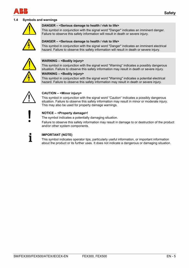
1.4 Symbols and warnings
DANGER – <Serious damage to health / risk to life>
This symbol in conjunction with the signal word "Danger" indicates an imminent danger. Failure to observe this safety information will result in death or severe injury.
DANGER – <Serious damage to health / risk to life>
This symbol in conjunction with the signal word "Danger" indicates an imminent electrical hazard. Failure to observe this safety information will result in death or severe injury.
WARNING – <Bodily injury>
This symbol in conjunction with the signal word “Warning“ indicates a possibly dangerous situation. Failure to observe this safety information may result in death or severe injury.
WARNING – <Bodily injury>
This symbol in conjunction with the signal word "Warning" indicates a potential electrical hazard. Failure to observe this safety information may result in death or severe injury.
CAUTION – <Minor injury>
This symbol in conjunction with the signal word “Caution“ indicates a possibly dangerous situation. Failure to observe this safety information may result in minor or moderate injury. This may also be used for property damage warnings.
NOTICE – <Property damage>!
The symbol indicates a potentially damaging situation.
Failure to observe this safety information may result in damage to or destruction of the product and/or other system components.
IMPORTANT (NOTE)
This symbol indicates operator tips, particularly useful information, or important information about the product or its further uses. It does not indicate a dangerous or damaging situation.
Device designs
6 - EN FEX300, FEX500 SM/FEX300/FEX500/ATEX/IECEX-EN
2 Device designs
The devices are available in two series. ProcessMaster 300 / HygienicMaster 300 with basic functions and ProcessMaster 500 / HygienicMaster 500 with extended functions and options.
The series is identified by the fourth digit of the model number:
Model number / device series
FEP3... ProcessMaster 300 FEP5... ProcessMaster 500 FEH3... HygienicMaster 300 FEH5... HygienicMaster 500
Devices suitable for use in potentially explosive atmospheres feature the corresponding Ex mark on their name plates.
The design intended for use in Ex Zones 2, 21, and 22 is identified by the letter "M" in the model number, while the design intended for use in Zones 1 and 21 is identified by the letter "L".
Example:
FEP315-100A1S1D2B0A1A0M1A1C1, FEP325-100A1S1D2B0A1A1M1A0Y1, FET325-1A0M1A1C1
2.1 Model with compact design
The transmitter and the flowmeter sensor form a single mechanical entity.
IMPORTANT (NOTE)
For further information about the instruments' explosion protection approval please refer to the Ex test certificates (available on the product CD or under www.abb.com/flow).
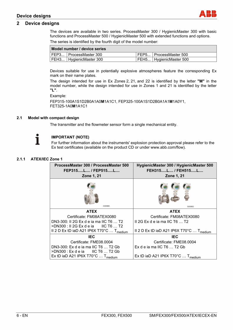
2.1.1 ATEX/IEC Zone 1
ProcessMaster 300 / ProcessMaster 500 HygienicMaster 300 / HygienicMaster 500 FEP315.....L.... / FEP515.....L.... FEH315.....L.... / FEH515.....L....
Zone 1, 21 Zone 1, 21
G00886 G00883 ATEX ATEX
Certificate: FM08ATEX0080 Certificate: FM08ATEX0080 DN3-300: II 2G Ex d e ia ma IIC T6 … T2 >DN300 : II 2G Ex d e ia IIC T6 … T2
II 2G Ex d e ia ma IIC T6 … T2
II 2 D Ex tD iaD A21 IP6X T70°C … Tmedium II 2 D Ex tD iaD A21 IP6X T70°C … Tmedium
IEC IEC Certificate: FME08.0004 Certificate: FME08.0004
DN3-300: Ex d e ia ma IIC T6 … T2 Gb >DN300 : Ex d e ia IIC T6 … T2 Gb
Ex d e ia ma IIC T6 … T2 Gb
Ex tD iaD A21 IP6X T70°C … Tmedium Ex tD iaD A21 IP6X T70°C … Tmedium
Device designs
SM/FEX300/FEX500/ATEX/IECEX-EN FEX300, FEX500 EN - 7
2.1.2 ATEX/IEC Zone 2
ProcessMaster 300 / ProcessMaster 500 HygienicMaster 300 / HygienicMaster 500 FEP315.....M.... / FEP515.....M.... FEH315.....M.... / FEH515.....M....
Zones 2, 21, 22 Zones 2, 21, 22
ATEX ATEX
Certificate: FM08ATEX0038, FM08ATEX0080 Certificate: FM08ATEX0038, FM08ATEX0080 II 3 G Ex nA nC IIC T4 … T3 II 3 G Ex nA nC IIC T4 … T3 II 2 D Ex tD A21 IP6X T70 °C … Tmedium II 2 D Ex tD A21 IP6X T70 °C … Tmedium
IEC IEC Certificate: FME08.0004 Certificate: FME08.0004
Ex nA nC IIC T4 … T3 Ex nA nC IIC T4 … T3 Ex tD A21 IP6X T70 °C … Tmedium Ex tD A21 IP6X T70 °C … Tmedium
1) Single-compartment housing 2) Dual-compartment housing
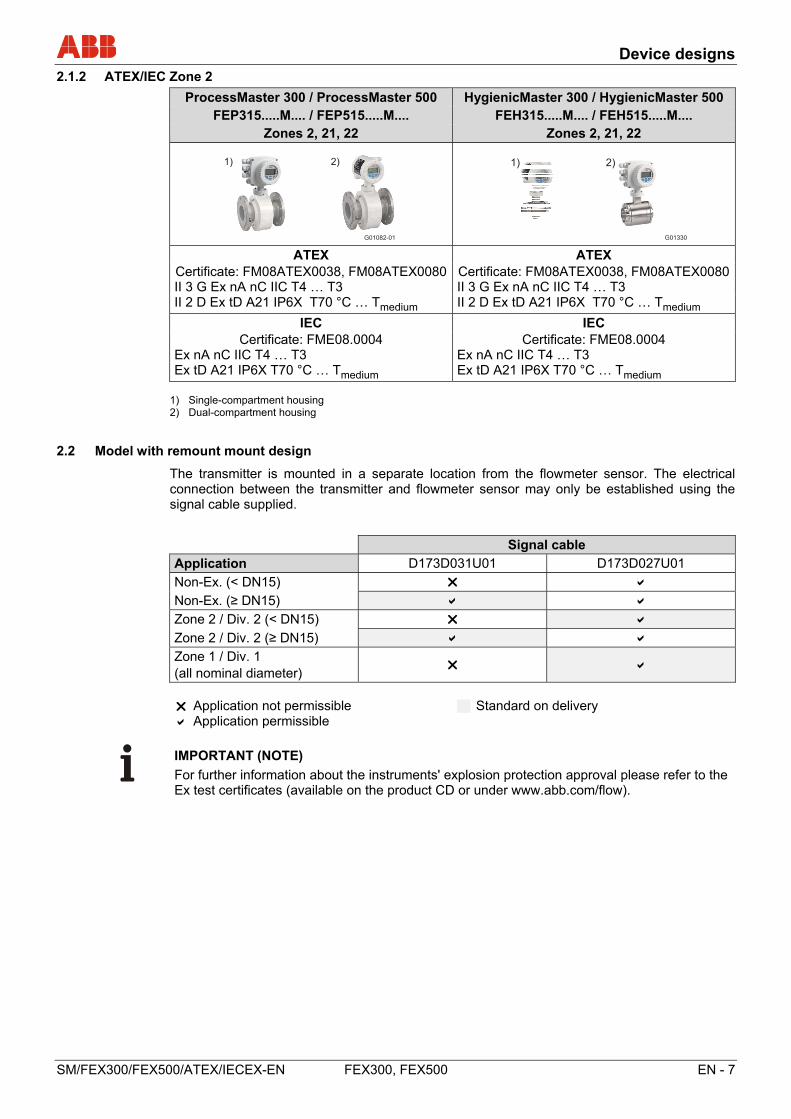
2.2 Model with remount mount design
The transmitter is mounted in a separate location from the flowmeter sensor. The electrical connection between the transmitter and flowmeter sensor may only be established using the signal cable supplied.
Signal cable
Application D173D031U01 D173D027U01
Non-Ex. (< DN15)
Non-Ex. (≥ DN15)
Zone 2 / Div. 2 (< DN15)
Zone 2 / Div. 2 (≥ DN15)
Zone 1 / Div. 1 (all nominal diameter)
Application not permissible Application permissible
Standard on delivery
IMPORTANT (NOTE)
For further information about the instruments' explosion protection approval please refer to the Ex test certificates (available on the product CD or under www.abb.com/flow).
G01082-01
1) 2)
G01330
1) 2)
Device designs
8 - EN FEX300, FEX500 SM/FEX300/FEX500/ATEX/IECEX-EN
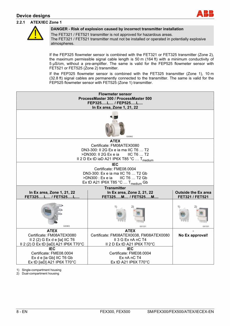
2.2.1 ATEX/IEC Zone 1
DANGER - Risk of explosion caused by incorrect transmitter installation
The FET321 / FET521 transmitter is not approved for hazardous areas. The FET321 / FET521 transmitter must not be installed or operated in potentially explosive atmospheres.
If the FEP325 flowmeter sensor is combined with the FET321 or FET325 transmitter (Zone 2), the maximum permissible signal cable length is 50 m (164 ft) with a minimum conductivity of 5 µS/cm, without a pre-amplifier. The same is valid for the FEP525 flowmeter sensor with FET521 or FET525 (Zone 2) transmitter.
If the FEP325 flowmeter sensor is combined with the FET325 transmitter (Zone 1), 10 m (32.8 ft) signal cables are permanently connected to the transmitter. The same is valid for the FEP525 flowmeter sensor with FET525 (Zone 1) transmitter.
Flowmeter sensor ProcessMaster 300 / ProcessMaster 500
FEP325.....L.... / FEP525.....L.... In Ex area, Zone 1, 21, 22
G00862 ATEX
Certificate: FM08ATEX0080 DN3-300: II 2G Ex e ia ma IIC T6 … T2 >DN300: II 2G Ex e ia IIC T6 … T2
II 2 D Ex tD iaD A21 IP6X T85 °C … Tmedium
IEC Certificate: FME08.0004
DN3-300: Ex e ia ma IIC T6 … T2 Gb >DN300 : Ex e ia IIC T6 … T2 Gb Ex tD A21 IP6X T85 °C … Tmedium Gb
Transmitter In Ex area, Zone 1, 21, 22 In Ex area, Zone 2, 21, 22 Outside the Ex area
FET325.....L.... / FET525.....L.... FET325.....M.... / FET525.....M.... FET321 / FET521
G00863 ATEX ATEX -
Certificate: FM08ATEX0080 Certificate: FM08ATEX0038, FM08ATEX0080 No Ex approval! II 2 (2) G Ex d e [ia] IIC T6 II 3 G Ex nA nC T4
II 2 (2) D Ex tD [iaD] A21 IP6X T70°C II 2 D Ex tD A21 IP6X T70°C IEC IEC
Certificate: FME08.0004 Certificate: FME08.0004 Ex d e [ia Gb] IIC T6 Gb Ex nA nC T4
Ex tD [iaD] A21 IP6X T70°C Ex tD A21 IP6X T70°C 1) Single-compartment housing 2) Dual-compartment housing
G01331
1) 2)
G01331
1) 2)
Device designs
SM/FEX300/FEX500/ATEX/IECEX-EN FEX300, FEX500 EN - 9
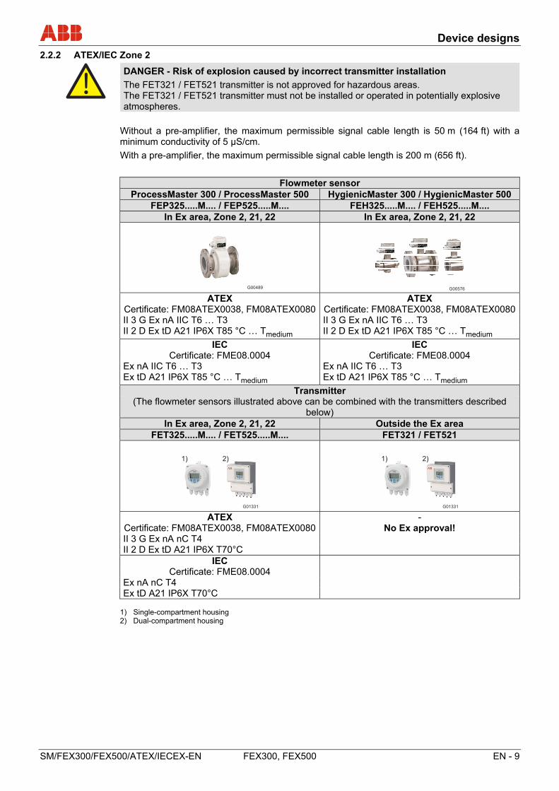
2.2.2 ATEX/IEC Zone 2
DANGER - Risk of explosion caused by incorrect transmitter installation
The FET321 / FET521 transmitter is not approved for hazardous areas. The FET321 / FET521 transmitter must not be installed or operated in potentially explosive atmospheres.
Without a pre-amplifier, the maximum permissible signal cable length is 50 m (164 ft) with a minimum conductivity of 5 µS/cm.
With a pre-amplifier, the maximum permissible signal cable length is 200 m (656 ft).
Flowmeter sensor ProcessMaster 300 / ProcessMaster 500 HygienicMaster 300 / HygienicMaster 500
FEP325.....M.... / FEP525.....M.... FEH325.....M.... / FEH525.....M.... In Ex area, Zone 2, 21, 22 In Ex area, Zone 2, 21, 22
ATEX ATEX
Certificate: FM08ATEX0038, FM08ATEX0080 Certificate: FM08ATEX0038, FM08ATEX0080 II 3 G Ex nA IIC T6 … T3 II 3 G Ex nA IIC T6 … T3 II 2 D Ex tD A21 IP6X T85 °C … Tmedium II 2 D Ex tD A21 IP6X T85 °C … Tmedium
IEC IEC Certificate: FME08.0004 Certificate: FME08.0004
Ex nA IIC T6 … T3 Ex nA IIC T6 … T3 Ex tD A21 IP6X T85 °C … Tmedium Ex tD A21 IP6X T85 °C … Tmedium
Transmitter (The flowmeter sensors illustrated above can be combined with the transmitters described
below) In Ex area, Zone 2, 21, 22 Outside the Ex area
FET325.....M.... / FET525.....M.... FET321 / FET521
ATEX -
Certificate: FM08ATEX0038, FM08ATEX0080 No Ex approval! II 3 G Ex nA nC T4 II 2 D Ex tD A21 IP6X T70°C
IEC Certificate: FME08.0004
Ex nA nC T4 Ex tD A21 IP6X T70°C
1) Single-compartment housing 2) Dual-compartment housing
G01331
1) 2)
G01331
1) 2)
Device designs
10 - EN FEX300, FEX500 SM/FEX300/FEX500/ATEX/IECEX-EN
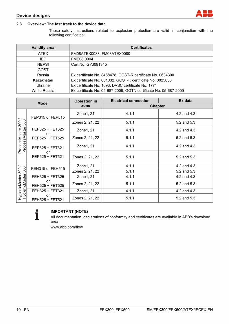
2.3 Overview: The fast track to the device data
These safety instructions related to explosion protection are valid in conjunction with the following certificates:
Validity area Certificates
ATEX FM08ATEX0038, FM08ATEX0080
IEC FME08.0004
NEPSI Cert No. GYJ091345
GOST Russia Ex certificate No. 8468478, GOST-R certificate No. 0634300
Kazakhstan Ex certificate No. 001032, GOST-K certificate No. 0025653 Ukraine Ex certificate No. 1093, DVSC certificate No. 1771
White Russia Ex certificate No. 05-687-2009, GGTN certificate No. 05-687-2009
Model Operation in
zone Electrical connection Ex data
Chapter
Pro
cess
Mas
ter
300
/ P
roce
ssM
aste
r 50
0
FEP315 or FEP515 Zone1, 21 4.1.1 4.2 and 4.3
Zones 2, 21, 22 5.1.1 5.2 and 5.3
FEP325 + FET325 or
FEP525 + FET525
Zone1, 21 4.1.1 4.2 and 4.3
Zones 2, 21, 22 5.1.1 5.2 and 5.3
FEP325 + FET321 or
FEP525 + FET521
Zone1, 21 4.1.1 4.2 and 4.3
Zones 2, 21, 22 5.1.1 5.2 and 5.3
Hyg
ieni
cMas
ter
300
/ H
ygie
nicM
aste
r 50
0 FEH315 or FEH515 Zone1, 21 4.1.1 4.2 and 4.3
Zones 2, 21, 22 5.1.1 5.2 and 5.3
FEH325 + FET325 or
FEH525 + FET525
Zone1, 21 4.1.1 4.2 and 4.3
Zones 2, 21, 22 5.1.1 5.2 and 5.3
FEH325 + FET321 or
FEH525 + FET521
Zone1, 21 4.1.1 4.2 and 4.3
Zones 2, 21, 22 5.1.1 5.2 and 5.3
IMPORTANT (NOTE)
All documentation, declarations of conformity and certificates are available in ABB's download area.
www.abb.com/flow
Device designs
SM/FEX300/FEX500/ATEX/IECEX-EN FEX300, FEX500 EN - 11
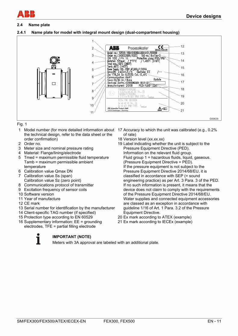
2.4 Name plate
2.4.1 Name plate for model with integral mount design (dual-compartment housing)
Fig. 1
1 Model number (for more detailed information about the technical design, refer to the data sheet or the order confirmation)
2 Order no. 3 Meter size and nominal pressure rating 4 Material: Flange/lining/electrode 5 Tmed = maximum permissible fluid temperature Tamb = maximum permissible ambient
temperature 6 Calibration value Qmax DN 7 Calibration value Ss (span) Calibration value Sz (zero point) 8 Communications protocol of transmitter 9 Excitation frequency of sensor coils 10 Software version 11 Year of manufacture 12 CE mark 13 Serial number for identification by the manufacturer 14 Client-specific TAG number (if specified) 15 Protection type according to EN 60529 16 Supplementary information: EE = grounding
electrodes, TFE = partial filling electrode
17 Accuracy to which the unit was calibrated (e.g., 0.2% of rate)
18 Version level (xx.xx.xx) 19 Label indicating whether the unit is subject to the
Pressure Equipment Directive (PED). Information on the relevant fluid group. Fluid group 1 = hazardous fluids, liquid, gaseous.
(Pressure Equipment Directive = PED). If the pressure equipment is not subject to the
Pressure Equipment Directive 2014/68/EU, it is classified in accordance with SEP (= sound engineering practice) as per Art. 3 Para. 3 of the PED.
If no such information is present, it means that the device does not claim to comply with the requirements of the Pressure Equipment Directive 2014/68/EU. Water supplies and connected equipment accessories are classed as an exception in accordance with guideline 1/16 of Art. 1 Para. 3.2 of the Pressure Equipment Directive.
20 Ex mark according to ATEX (example) 21 Ex mark according to IECEx (example)
IMPORTANT (NOTE)
Meters with 3A approval are labeled with an additional plate.
G00629
PN 16
37079 Goettingen - Germany
1
2
3
4
5
6
7
8
9
10
11
12
13
14
15
16
17
18
19
20
21
Device designs
12 - EN FEX300, FEX500 SM/FEX300/FEX500/ATEX/IECEX-EN
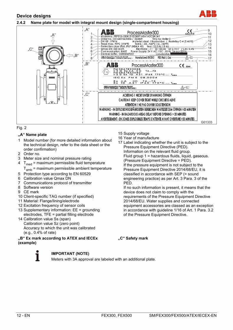
2.4.2 Name plate for model with integral mount design (single-compartment housing)
Fig. 2
„A“ Name plate
1 Model number (for more detailed information about the technical design, refer to the data sheet or the order confirmation)
2 Order no. 3 Meter size and nominal pressure rating 4 Tmed = maximum permissible fluid temperature
Tamb = maximum permissible ambient temperature
5 Protection type according to EN 60529 6 Calibration value Qmax DN 7 Communications protocol of transmitter 8 Software version 9 CE mark 10 Client-specific TAG number (if specified) 11 Material: Flange/lining/electrode 12 Excitation frequency of sensor coils 13 Supplementary information: EE = grounding
electrodes, TFE = partial filling electrode 14 Calibration value Ss (span) Calibration value Sz (zero point) Accuracy to which the unit was calibrated
(e.g., 0.4% of rate)
15Supply voltage 16 Year of manufacture 17 Label indicating whether the unit is subject to the
Pressure Equipment Directive (PED). Information on the relevant fluid group. Fluid group 1 = hazardous fluids, liquid, gaseous.
(Pressure Equipment Directive = PED). If the pressure equipment is not subject to the
Pressure Equipment Directive 2014/68/EU, it is classified in accordance with SEP (= sound engineering practice) as per Art. 3 Para. 3 of the PED.
If no such information is present, it means that the device does not claim to comply with the requirements of the Pressure Equipment Directive 2014/68/EU. Water supplies and connected equipment accessories are classed as an exception in accordance with guideline 1/16 of Art. 1 Para. 3.2 of the Pressure Equipment Directive.
„B“ Ex mark according to ATEX and IECEx (example)
„C“ Safety mark
IMPORTANT (NOTE)
Meters with 3A approval are labeled with an additional plate.
G01333
123
456
78
910
111213
141516
17
„A“
„B“
„C“
„A“
„B“
„C“
Device designs
SM/FEX300/FEX500/ATEX/IECEX-EN FEX300, FEX500 EN - 13
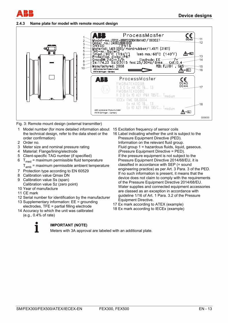
2.4.3 Name plate for model with remote mount design
G00630
1
2
345
67
89
10
11
12
1314
15
16
17
18
FEP325
Fig. 3: Remote mount design (external transmitter)
1 Model number (for more detailed information about the technical design, refer to the data sheet or the order confirmation)
2 Order no. 3 Meter size and nominal pressure rating 4 Material: Flange/lining/electrode 5 Client-specific TAG number (if specified) 6 Tmed = maximum permissible fluid temperature
Tamb = maximum permissible ambient temperature
7 Protection type according to EN 60529 8 Calibration value Qmax DN 9 Calibration value Ss (span) Calibration value Sz (zero point) 10 Year of manufacture 11CE mark 12Serial number for identification by the manufacturer 13Supplementary information: EE = grounding
electrodes, TFE = partial filling electrode 14Accuracy to which the unit was calibrated
(e.g., 0.4% of rate)
15Excitation frequency of sensor coils 16Label indicating whether the unit is subject to the
Pressure Equipment Directive (PED). Information on the relevant fluid group. Fluid group 1 = hazardous fluids, liquid, gaseous.
(Pressure Equipment Directive = PED). If the pressure equipment is not subject to the
Pressure Equipment Directive 2014/68/EU, it is classified in accordance with SEP (= sound engineering practice) as per Art. 3 Para. 3 of the PED.
If no such information is present, it means that the device does not claim to comply with the requirements of the Pressure Equipment Directive 2014/68/EU. Water supplies and connected equipment accessories are classed as an exception in accordance with guideline 1/16 of Art. 1 Para. 3.2 of the Pressure Equipment Directive.
17Ex mark according to ATEX (example) 18Ex mark according to IECEx (example)
IMPORTANT (NOTE)
Meters with 3A approval are labeled with an additional plate.
Device designs
14 - EN FEX300, FEX500 SM/FEX300/FEX500/ATEX/IECEX-EN
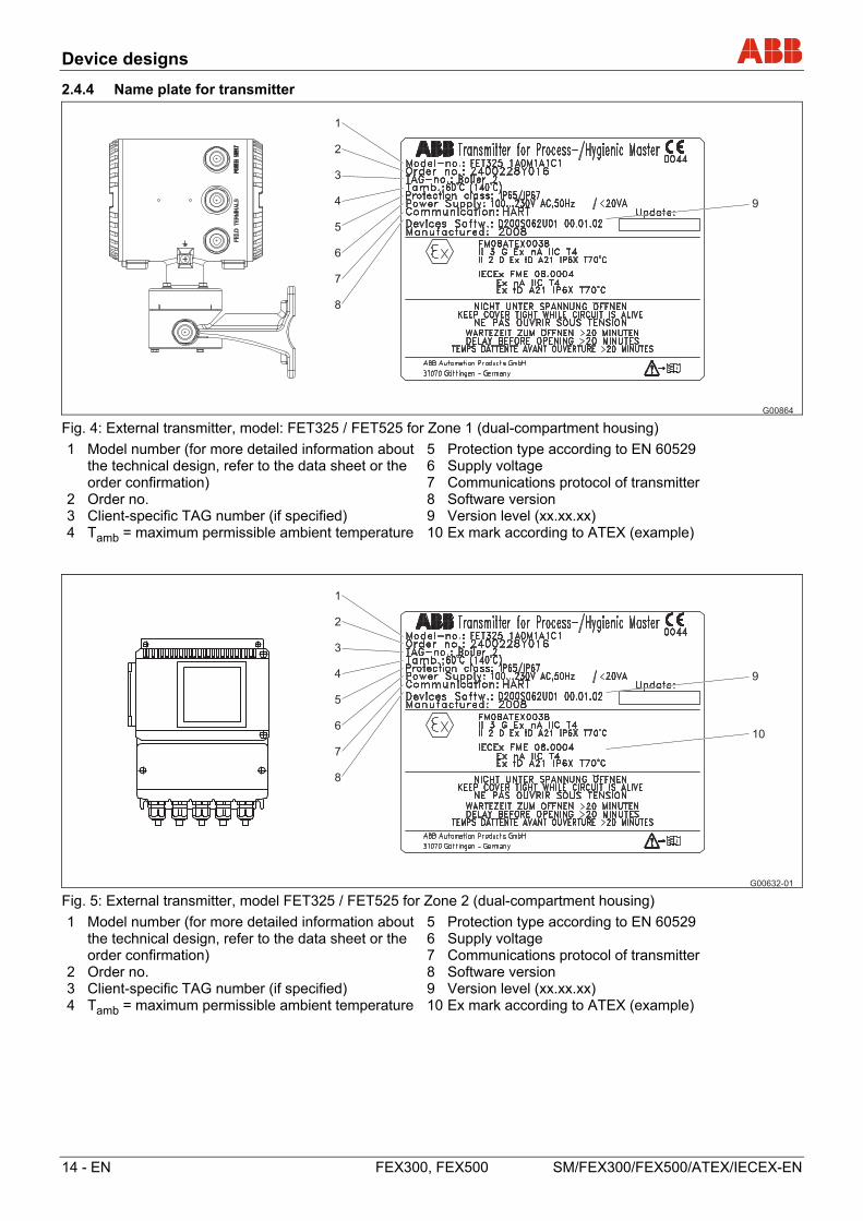
2.4.4 Name plate for transmitter
G00864
1
2
3
4
5
6
7
8
9
Fig. 4: External transmitter, model: FET325 / FET525 for Zone 1 (dual-compartment housing)
1 Model number (for more detailed information about the technical design, refer to the data sheet or the order confirmation)
2 Order no. 3 Client-specific TAG number (if specified) 4 Tamb = maximum permissible ambient temperature
5 Protection type according to EN 60529 6 Supply voltage 7 Communications protocol of transmitter 8 Software version 9 Version level (xx.xx.xx) 10Ex mark according to ATEX (example)
G00632-01
1
2
3
4
5
6
7
8
9
10
Fig. 5: External transmitter, model FET325 / FET525 for Zone 2 (dual-compartment housing)
1 Model number (for more detailed information about the technical design, refer to the data sheet or the order confirmation)
2 Order no. 3 Client-specific TAG number (if specified) 4 Tamb = maximum permissible ambient temperature
5 Protection type according to EN 60529 6 Supply voltage 7 Communications protocol of transmitter 8 Software version 9 Version level (xx.xx.xx) 10Ex mark according to ATEX (example)
Device designs
SM/FEX300/FEX500/ATEX/IECEX-EN FEX300, FEX500 EN - 15
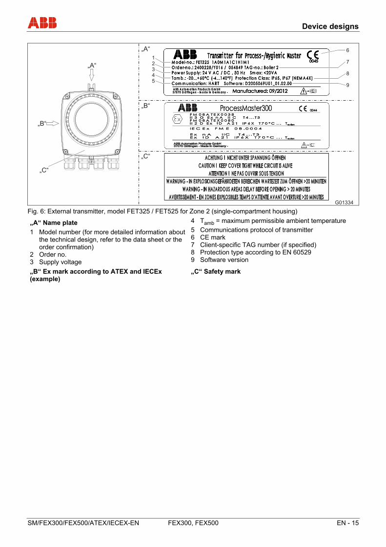
Fig. 6: External transmitter, model FET325 / FET525 for Zone 2 (single-compartment housing)
„A“ Name plate
1 Model number (for more detailed information about the technical design, refer to the data sheet or the order confirmation)
2 Order no. 3 Supply voltage
4 Tamb = maximum permissible ambient temperature
5 Communications protocol of transmitter 6 CE mark 7 Client-specific TAG number (if specified) 8 Protection type according to EN 60529 9 Software version
„B“ Ex mark according to ATEX and IECEx (example)
„C“ Safety mark
G01334
123
45
6
7
8
9
„A“
„B“
„C“
„A“
„B“
„C“
Mounting
16 - EN FEX300, FEX500 SM/FEX300/FEX500/ATEX/IECEX-EN
3 Mounting
3.1 Information about opening and closing the housing
G00758
1 1
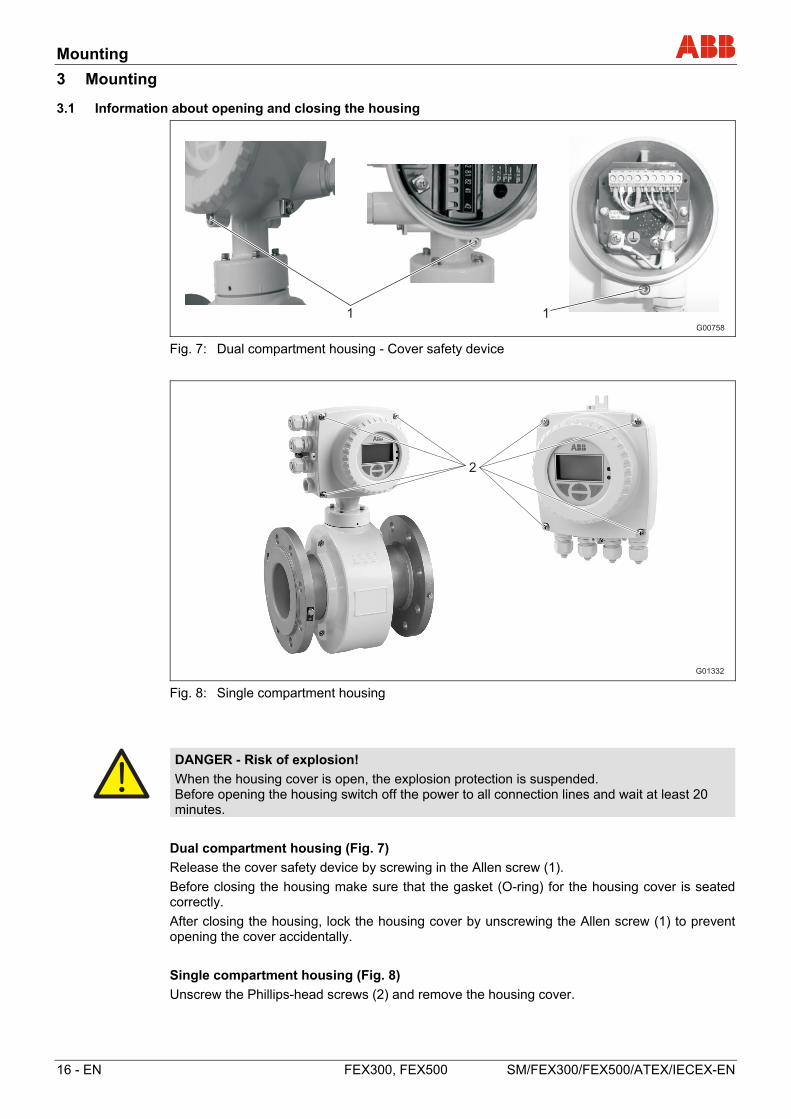
Fig. 7: Dual compartment housing - Cover safety device
Fig. 8: Single compartment housing
DANGER - Risk of explosion!
When the housing cover is open, the explosion protection is suspended. Before opening the housing switch off the power to all connection lines and wait at least 20 minutes.
Dual compartment housing (Fig. 7)
Release the cover safety device by screwing in the Allen screw (1).
Before closing the housing make sure that the gasket (O-ring) for the housing cover is seated correctly.
After closing the housing, lock the housing cover by unscrewing the Allen screw (1) to prevent opening the cover accidentally.
Single compartment housing (Fig. 8)
Unscrew the Phillips-head screws (2) and remove the housing cover.
G01332
2
Mounting
SM/FEX300/FEX500/ATEX/IECEX-EN FEX300, FEX500 EN - 17
3.2 Cable entries
Dual compartment housing Single compartment housing
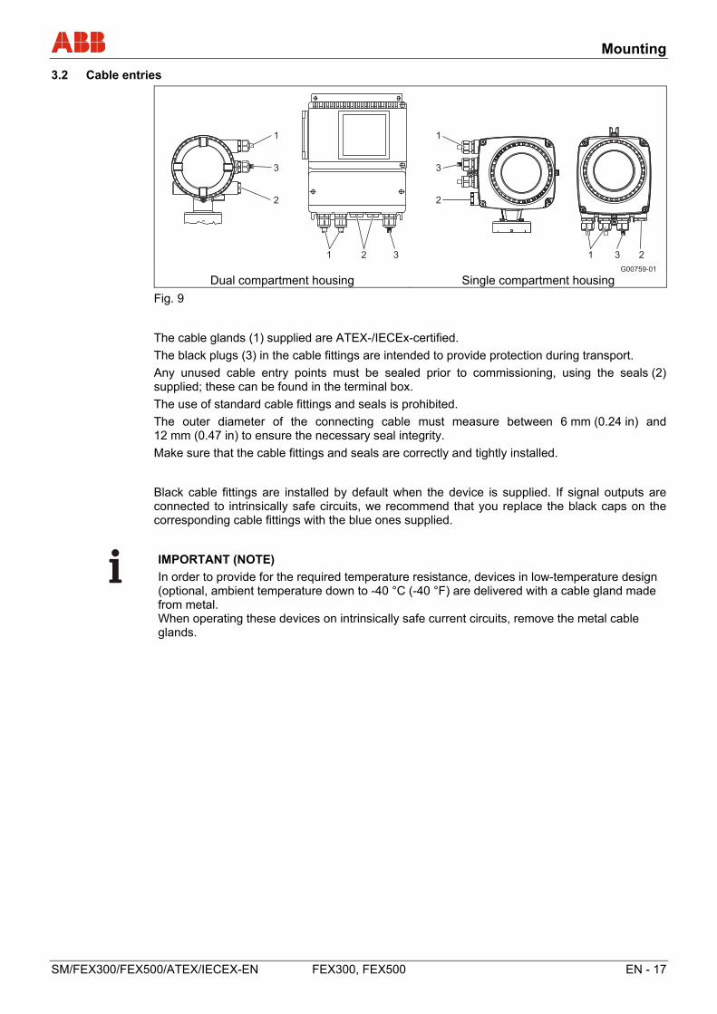
Fig. 9
The cable glands (1) supplied are ATEX-/IECEx-certified.
The black plugs (3) in the cable fittings are intended to provide protection during transport.
Any unused cable entry points must be sealed prior to commissioning, using the seals (2) supplied; these can be found in the terminal box.
The use of standard cable fittings and seals is prohibited.
The outer diameter of the connecting cable must measure between 6 mm (0.24 in) and 12 mm (0.47 in) to ensure the necessary seal integrity.
Make sure that the cable fittings and seals are correctly and tightly installed.
Black cable fittings are installed by default when the device is supplied. If signal outputs are connected to intrinsically safe circuits, we recommend that you replace the black caps on the corresponding cable fittings with the blue ones supplied.
IMPORTANT (NOTE)
In order to provide for the required temperature resistance, devices in low-temperature design (optional, ambient temperature down to -40 °C (-40 °F) are delivered with a cable gland made from metal. When operating these devices on intrinsically safe current circuits, remove the metal cable glands.
G00759-01
1
3
2
1 3 2
1
3
2
1 2 3
Mounting
18 - EN FEX300, FEX500 SM/FEX300/FEX500/ATEX/IECEX-EN
3.3 High temperature version
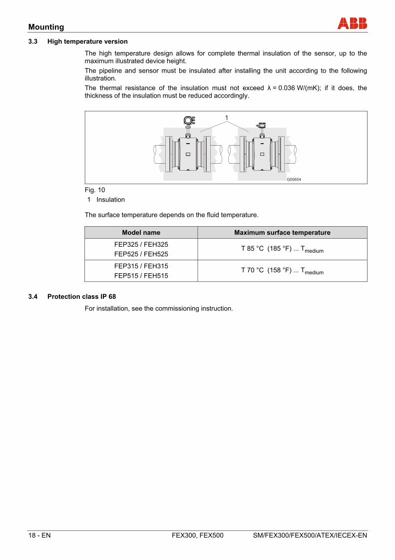
The high temperature design allows for complete thermal insulation of the sensor, up to the maximum illustrated device height.
The pipeline and sensor must be insulated after installing the unit according to the following illustration.
The thermal resistance of the insulation must not exceed λ = 0.036 W/(mK); if it does, the thickness of the insulation must be reduced accordingly.
G00654
1
Fig. 10
1 Insulation The surface temperature depends on the fluid temperature.
Model name Maximum surface temperature
FEP325 / FEH325
FEP525 / FEH525 T 85 °C (185 °F) ... Tmedium
FEP315 / FEH315
FEP515 / FEH515 T 70 °C (158 °F) ... Tmedium
3.4 Protection class IP 68
For installation, see the commissioning instruction.
Mounting
SM/FEX300/FEX500/ATEX/IECEX-EN FEX300, FEX500 EN - 19
3.5 Rotating the transmitter housing
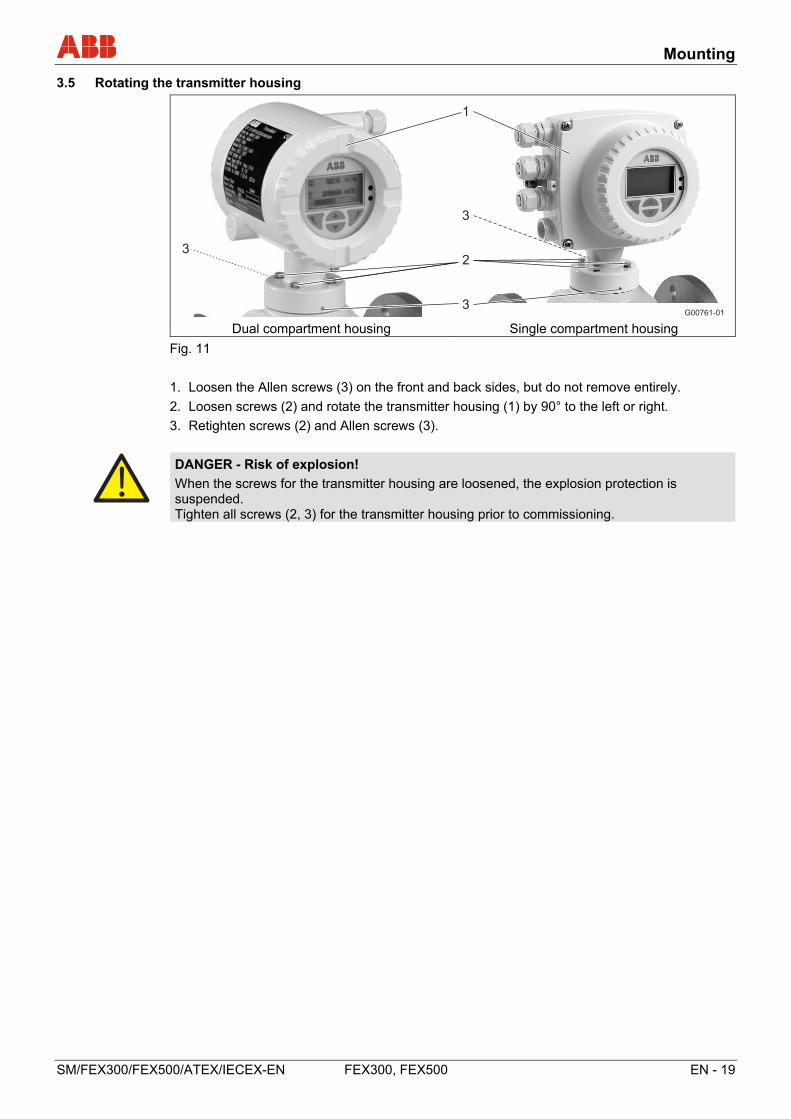
Dual compartment housing Single compartment housing
Fig. 11
1. Loosen the Allen screws (3) on the front and back sides, but do not remove entirely.
2. Loosen screws (2) and rotate the transmitter housing (1) by 90° to the left or right.
3. Retighten screws (2) and Allen screws (3).
DANGER - Risk of explosion!
When the screws for the transmitter housing are loosened, the explosion protection is suspended. Tighten all screws (2, 3) for the transmitter housing prior to commissioning.
G00761-01
1
3
2
3
3
Mounting
20 - EN FEX300, FEX500 SM/FEX300/FEX500/ATEX/IECEX-EN
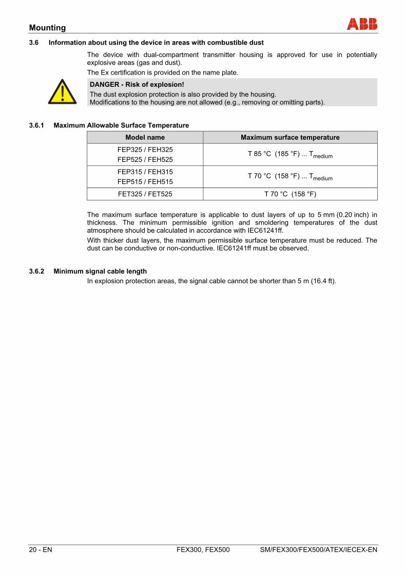
3.6 Information about using the device in areas with combustible dust
The device with dual-compartment transmitter housing is approved for use in potentially explosive areas (gas and dust).
The Ex certification is provided on the name plate.
DANGER - Risk of explosion!
The dust explosion protection is also provided by the housing. Modifications to the housing are not allowed (e.g., removing or omitting parts).
3.6.1 Maximum Allowable Surface Temperature
Model name Maximum surface temperature
FEP325 / FEH325
FEP525 / FEH525 T 85 °C (185 °F) ... Tmedium
FEP315 / FEH315
FEP515 / FEH515 T 70 °C (158 °F) ... Tmedium
FET325 / FET525 T 70 °C (158 °F)
The maximum surface temperature is applicable to dust layers of up to 5 mm (0.20 inch) in thickness. The minimum permissible ignition and smoldering temperatures of the dust atmosphere should be calculated in accordance with IEC61241ff.
With thicker dust layers, the maximum permissible surface temperature must be reduced. The dust can be conductive or non-conductive. IEC61241ff must be observed.
3.6.2 Minimum signal cable length
In explosion protection areas, the signal cable cannot be shorter than 5 m (16.4 ft).
Ex relevant specifications for operation in Zones 1, 21, and 22
SM/FEX300/FEX500/ATEX/IECEX-EN FEX300, FEX500 EN - 21
4 Ex relevant specifications for operation in Zones 1, 21, and 22
4.1 Electrical connection
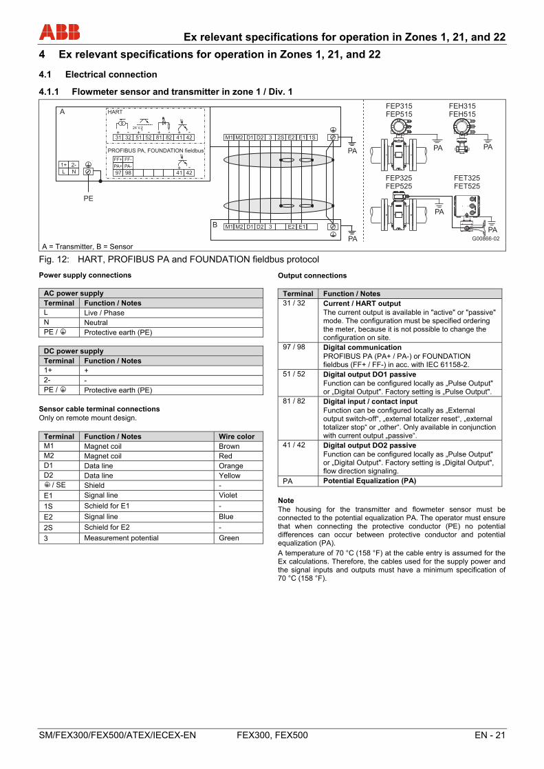
4.1.1 Flowmeter sensor and transmitter in zone 1 / Div. 1
G00866-02
31 32
A
24 V
51 52 81 82 41 42
L N
1+ 2-
M1 M2 D1 D2 3 2S E2 E1 1S
M1 M2 D1 D2 3 E2 E1B
PE
PA
+ - + - + - + -
HART
PA
97 98 41 42
PA+ PA-
FF+ FF-
+ -
PROFIBUS PA, FOUNDATION fieldbus
FEP315FEP515
FEP325FEP525
FET325FET525
PA
PA
PA
FEH315FEH515
PA
A = Transmitter, B = Sensor
Fig. 12: HART, PROFIBUS PA and FOUNDATION fieldbus protocol Change from one to two columns
Power supply connections
AC power supply Terminal Function / Notes L Live / Phase N Neutral PE / Protective earth (PE)
DC power supply Terminal Function / Notes 1+ + 2- - PE / Protective earth (PE)
Sensor cable terminal connections Only on remote mount design.
Terminal Function / Notes Wire color M1 Magnet coil Brown M2 Magnet coil Red D1 Data line Orange D2 Data line Yellow
/ SE Shield -
E1 Signal line Violet
1S Schield for E1 -
E2 Signal line Blue
2S Schield for E2 -
3 Measurement potential Green
Output connections
Terminal Function / Notes 31 / 32 Current / HART output
The current output is available in "active" or "passive" mode. The configuration must be specified ordering the meter, because it is not possible to change the configuration on site.
97 / 98 Digital communication PROFIBUS PA (PA+ / PA-) or FOUNDATION fieldbus (FF+ / FF-) in acc. with IEC 61158-2.
51 / 52 Digital output DO1 passive Function can be configured locally as „Pulse Output" or „Digital Output". Factory setting is „Pulse Output".
81 / 82 Digital input / contact input Function can be configured locally as „External output switch-off“, „external totalizer reset“, „external totalizer stop“ or „other“. Only available in conjunction with current output „passive“.
41 / 42 Digital output DO2 passive Function can be configured locally as „Pulse Output" or „Digital Output". Factory setting is „Digital Output", flow direction signaling.
PA Potential Equalization (PA)
Note The housing for the transmitter and flowmeter sensor must be connected to the potential equalization PA. The operator must ensure that when connecting the protective conductor (PE) no potential differences can occur between protective conductor and potential equalization (PA).
A temperature of 70 °C (158 °F) at the cable entry is assumed for the Ex calculations. Therefore, the cables used for the supply power and the signal inputs and outputs must have a minimum specification of 70 °C (158 °F).
Change from one to two columns
Ex relevant specifications for operation in Zones 1, 21, and 22
22 - EN FEX300, FEX500 SM/FEX300/FEX500/ATEX/IECEX-EN
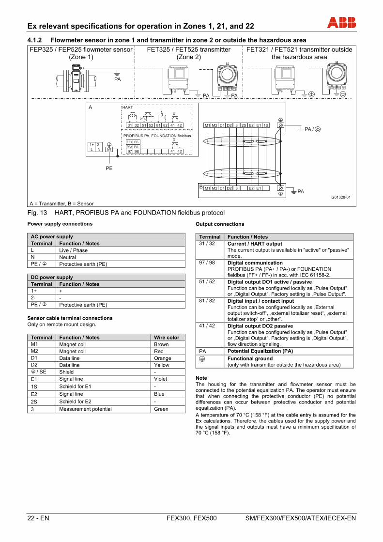
4.1.2 Flowmeter sensor in zone 1 and transmitter in zone 2 or outside the hazardous area
FEP325 / FEP525 flowmeter sensor (Zone 1)
FET325 / FET525 transmitter (Zone 2)
FET321 / FET521 transmitter outside the hazardous area
A = Transmitter, B = Sensor
Fig. 13 HART, PROFIBUS PA and FOUNDATION fieldbus protocol Change from one to two columns
Power supply connections
AC power supply Terminal Function / Notes L Live / Phase N Neutral PE / Protective earth (PE)
DC power supply Terminal Function / Notes 1+ + 2- - PE / Protective earth (PE)
Sensor cable terminal connections Only on remote mount design.
Terminal Function / Notes Wire color M1 Magnet coil Brown M2 Magnet coil Red D1 Data line Orange D2 Data line Yellow
/ SE Shield -
E1 Signal line Violet
1S Schield for E1 -
E2 Signal line Blue
2S Schield for E2 -
3 Measurement potential Green
Output connections
Terminal Function / Notes 31 / 32 Current / HART output
The current output is available in "active" or "passive" mode.
97 / 98 Digital communication PROFIBUS PA (PA+ / PA-) or FOUNDATION fieldbus (FF+ / FF-) in acc. with IEC 61158-2.
51 / 52 Digital output DO1 active / passive Function can be configured locally as „Pulse Output" or „Digital Output". Factory setting is „Pulse Output".
81 / 82 Digital input / contact input Function can be configured locally as „External output switch-off“, „external totalizer reset“, „external totalizer stop“ or „other“.
41 / 42 Digital output DO2 passive Function can be configured locally as „Pulse Output" or „Digital Output". Factory setting is „Digital Output", flow direction signaling.
PA Potential Equalization (PA)
Functional ground (only with transmitter outside the hazardous area)
Note The housing for the transmitter and flowmeter sensor must be connected to the potential equalization PA. The operator must ensure that when connecting the protective conductor (PE) no potential differences can occur between protective conductor and potential equalization (PA).
A temperature of 70 °C (158 °F) at the cable entry is assumed for the Ex calculations. Therefore, the cables used for the supply power and the signal inputs and outputs must have a minimum specification of 70 °C (158 °F).
Change from one to two columns
G01328-01
31 32
A
24 V
51 52 81 82 41 42
L N
1+ 2-
M1 M2 D1 D2 3 2S E2 E1 1S
M1 M2 D1 D2 3 E2 E1B
PE
PA
97 98 41 42
PA+ PA-
FF+ FF-
+ -
+ - + - + - + -
HART
PROFIBUS PA, FOUNDATION fieldbus
PA /
PA
PA PA
Ex relevant specifications for operation in Zones 1, 21, and 22
SM/FEX300/FEX500/ATEX/IECEX-EN FEX300, FEX500 EN - 23
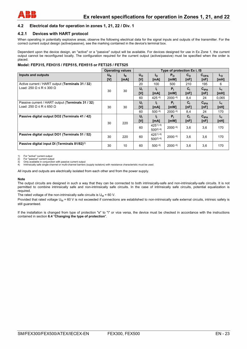
4.2 Electrical data for operation in zones 1, 21, 22 / Div. 1
4.2.1 Devices with HART protocol
When operating in potentially explosive areas, observe the following electrical data for the signal inputs and outputs of the transmitter. For the correct current output design (active/passive), see the marking contained in the device's terminal box.
Dependent upon the device design, an "active" or a "passive" output will be available. For devices designed for use in Ex Zone 1, the current output cannot be reconfigured locally. The configuration required for the current output (active/passive) must be specified when the order is placed.
Model: FEP315, FEH315 / FEP515, FEH515 or FET325 / FET525
Operating values Type of protection Ex i, IS Inputs and outputs UN
[V] IN
[mA] UO [V]
IO [mA]
PO [mW]
CO [nF]
COPA [nF]
LO [mH]
Active current / HART output (Terminals 31 / 32) Load: 250 Ω ≤ R ≤ 300 Ω
30 30
20 100 500 210 195 6
UI [V]
II [mA]
PI [mW]
CI [nF]
CIPA [nF]
LI [mH]
60 425 4) 2000 4) 8,4 24 0,065
Passive current / HART output (Terminals 31 / 32) Load: 250 Ω ≤ R ≤ 650 Ω 30 30
UI [V]
II [mA]
PI [mW]
CI [nF]
CIPA [nF]
LI [nH]
60 500 4) 2000 4) 8,4 24 170
Passive digital output DO2 (Terminals 41 / 42)
30 220
UI [V]
II [mA]
PI [mW]
CI [nF]
CIPA [nF]
LI [nH]
60 4251) 4) 5002) 4)
2000 4) 3,6 3,6 170
Passive digital output DO1 (Terminals 51 / 52) 30 220 60
4251) 4) 5002) 4)
2000 4) 3,6 3,6 170
Passive digital input DI (Terminals 81/82)3)
30 10 60 500 4) 2000 4) 3,6 3,6 170
1) For "active" current output 2) For "passive" current output 3) Only available in conjunction with passive current output 4) Intrinsically safe single-channel or multi-channel barriers (supply isolators) with resistance characteristic must be used.
All inputs and outputs are electrically isolated from each other and from the power supply. Note The output circuits are designed in such a way that they can be connected to both intrinsically-safe and non-intrinsically-safe circuits. It is not permitted to combine intrinsically safe and non-intrinsically safe circuits. In the case of intrinsically safe circuits, potential equalization is required. The rated voltage of the non-intrinsically safe circuits is UM = 60 V.
Provided that rated voltage UM = 60 V is not exceeded if connections are established to non-intrinsically safe external circuits, intrinsic safety is still guaranteed.
If the installation is changed from type of protection "e" to "i" or vice versa, the device must be checked in accordance with the instructions contained in section 6.4 "Changing the type of protection".
Ex relevant specifications for operation in Zones 1, 21, and 22
24 - EN FEX300, FEX500 SM/FEX300/FEX500/ATEX/IECEX-EN
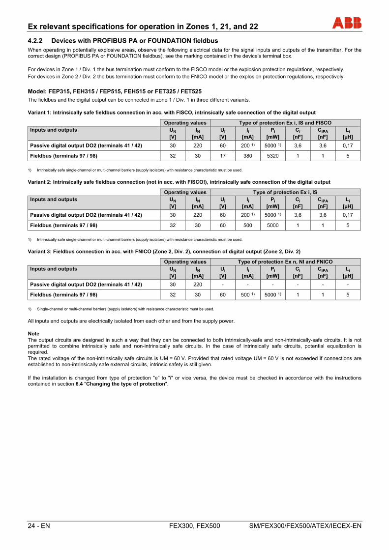
4.2.2 Devices with PROFIBUS PA or FOUNDATION fieldbus
When operating in potentially explosive areas, observe the following electrical data for the signal inputs and outputs of the transmitter. For the correct design (PROFIBUS PA or FOUNDATION fieldbus), see the marking contained in the device's terminal box.
For devices in Zone 1 / Div. 1 the bus termination must conform to the FISCO model or the explosion protection regulations, respectively.
For devices in Zone 2 / Div. 2 the bus termination must conform to the FNICO model or the explosion protection regulations, respectively.
Model: FEP315, FEH315 / FEP515, FEH515 or FET325 / FET525
The fieldbus and the digital output can be connected in zone 1 / Div. 1 in three different variants. Variant 1: Intrinsically safe fieldbus connection in acc. with FISCO, intrinsically safe connection of the digital output
Operating values Type of protection Ex i, IS and FISCO Inputs and outputs UN
[V] IN
[mA] Ui [V]
Ii [mA]
Pi [mW]
Ci [nF]
CiPA [nF]
Li [µH]
Passive digital output DO2 (terminals 41 / 42) 30 220 60 200 1) 5000 1) 3,6 3,6 0,17
Fieldbus (terminals 97 / 98) 32 30 17 380 5320 1 1 5
1) Intrinsically safe single-channel or multi-channel barriers (supply isolators) with resistance characteristic must be used.
Variant 2: Intrinsically safe fieldbus connection (not in acc. with FISCO!), intrinsically safe connection of the digital output
Operating values Type of protection Ex i, IS Inputs and outputs UN
[V] IN
[mA] Ui [V]
Ii [mA]
Pi [mW]
Ci [nF]
CiPA [nF]
Li [µH]
Passive digital output DO2 (terminals 41 / 42) 30 220 60 200 1) 5000 1) 3,6 3,6 0,17
Fieldbus (terminals 97 / 98) 32 30 60 500 5000 1 1 5
1) Intrinsically safe single-channel or multi-channel barriers (supply isolators) with resistance characteristic must be used.
Variant 3: Fieldbus connection in acc. with FNICO (Zone 2, Div. 2), connection of digital output (Zone 2, Div. 2)
Operating values Type of protection Ex n, NI and FNICO Inputs and outputs UN
[V] IN
[mA] Ui [V]
Ii [mA]
Pi [mW]
Ci [nF]
CiPA [nF]
Li [µH]
Passive digital output DO2 (terminals 41 / 42) 30 220 - - - - - -
Fieldbus (terminals 97 / 98) 32 30 60 500 1) 5000 1) 1 1 5
1) Single-channel or multi-channel barriers (supply isolators) with resistance characteristic must be used.
All inputs and outputs are electrically isolated from each other and from the supply power. Note The output circuits are designed in such a way that they can be connected to both intrinsically-safe and non-intrinsically-safe circuits. It is not permitted to combine intrinsically safe and non-intrinsically safe circuits. In the case of intrinsically safe circuits, potential equalization is required. The rated voltage of the non-intrinsically safe circuits is UM = 60 V. Provided that rated voltage UM = 60 V is not exceeded if connections are established to non-intrinsically safe external circuits, intrinsic safety is still given.
If the installation is changed from type of protection "e" to "i" or vice versa, the device must be checked in accordance with the instructions contained in section 6.4 "Changing the type of protection".
Ex relevant specifications for operation in Zones 1, 21, and 22
SM/FEX300/FEX500/ATEX/IECEX-EN FEX300, FEX500 EN - 25
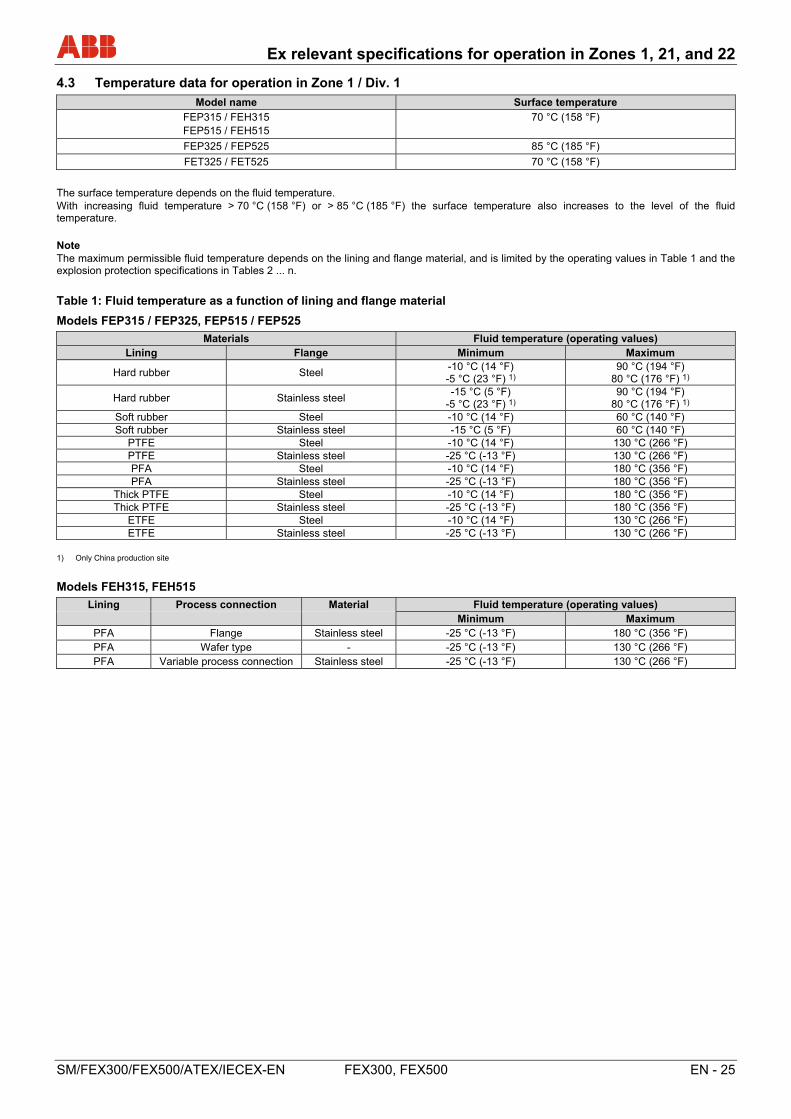
4.3 Temperature data for operation in Zone 1 / Div. 1
Model name Surface temperature
FEP315 / FEH315 FEP515 / FEH515
70 °C (158 °F)
FEP325 / FEP525 85 °C (185 °F)
FET325 / FET525 70 °C (158 °F)
The surface temperature depends on the fluid temperature. With increasing fluid temperature > 70 °C (158 °F) or > 85 °C (185 °F) the surface temperature also increases to the level of the fluid temperature.
Note The maximum permissible fluid temperature depends on the lining and flange material, and is limited by the operating values in Table 1 and the explosion protection specifications in Tables 2 ... n.
Table 1: Fluid temperature as a function of lining and flange material
Models FEP315 / FEP325, FEP515 / FEP525
Materials Fluid temperature (operating values) Lining Flange Minimum Maximum
Hard rubber Steel -10 °C (14 °F) -5 °C (23 °F) 1)
90 °C (194 °F) 80 °C (176 °F) 1)
Hard rubber Stainless steel -15 °C (5 °F)
-5 °C (23 °F) 1) 90 °C (194 °F)
80 °C (176 °F) 1) Soft rubber Steel -10 °C (14 °F) 60 °C (140 °F) Soft rubber Stainless steel -15 °C (5 °F) 60 °C (140 °F)
PTFE Steel -10 °C (14 °F) 130 °C (266 °F) PTFE Stainless steel -25 °C (-13 °F) 130 °C (266 °F) PFA Steel -10 °C (14 °F) 180 °C (356 °F) PFA Stainless steel -25 °C (-13 °F) 180 °C (356 °F)
Thick PTFE Steel -10 °C (14 °F) 180 °C (356 °F) Thick PTFE Stainless steel -25 °C (-13 °F) 180 °C (356 °F)
ETFE Steel -10 °C (14 °F) 130 °C (266 °F) ETFE Stainless steel -25 °C (-13 °F) 130 °C (266 °F)
1) Only China production site
Models FEH315, FEH515
Lining Process connection Material Fluid temperature (operating values) Minimum Maximum
PFA Flange Stainless steel -25 °C (-13 °F) 180 °C (356 °F) PFA Wafer type - -25 °C (-13 °F) 130 °C (266 °F) PFA Variable process connection Stainless steel -25 °C (-13 °F) 130 °C (266 °F)
Ex relevant specifications for operation in Zones 1, 21, and 22
26 - EN FEX300, FEX500 SM/FEX300/FEX500/ATEX/IECEX-EN
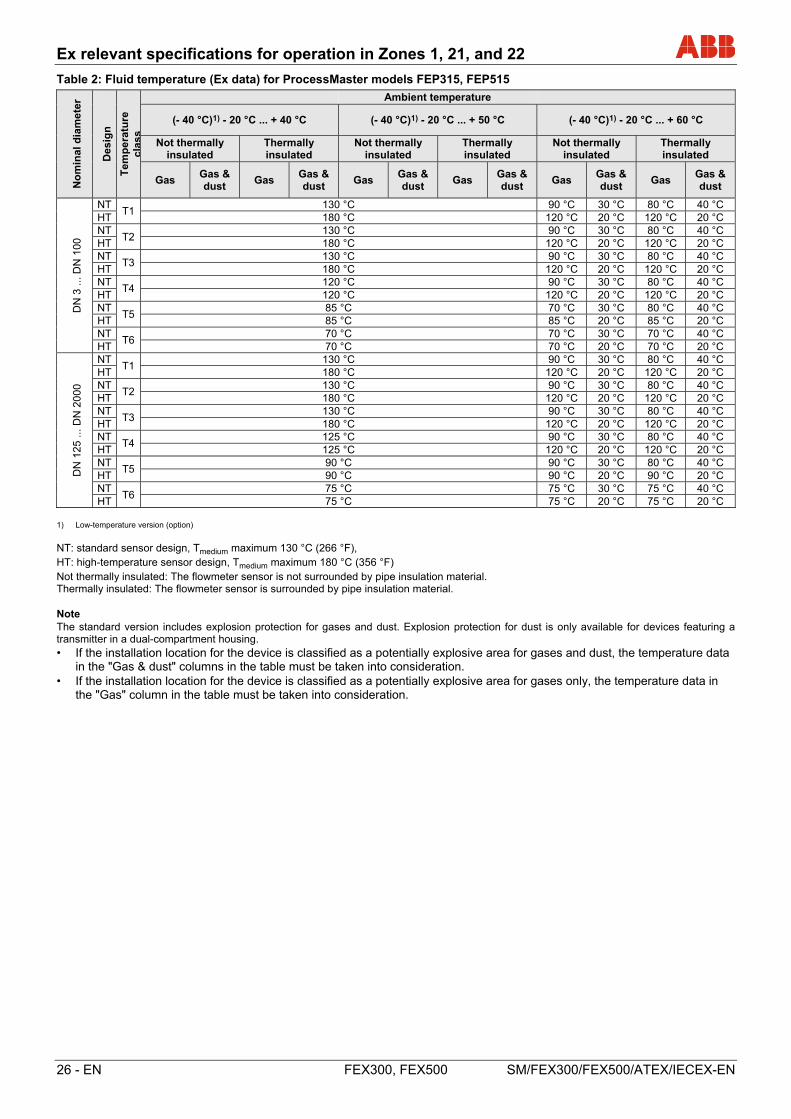
Table 2: Fluid temperature (Ex data) for ProcessMaster models FEP315, FEP515
No
min
al d
iam
ete
r
Des
ign
Tem
per
atu
re
clas
s
Ambient temperature
(- 40 °C)1) - 20 °C ... + 40 °C (- 40 °C)1) - 20 °C ... + 50 °C (- 40 °C)1) - 20 °C ... + 60 °C
Not thermally insulated
Thermally insulated
Not thermally insulated
Thermally insulated
Not thermally insulated
Thermally insulated
Gas Gas & dust
Gas Gas & dust
Gas Gas & dust
Gas Gas & dust
Gas Gas & dust
Gas Gas & dust
DN
3 ..
. DN
100
NT T1
130 °C 90 °C 30 °C 80 °C 40 °C HT 180 °C 120 °C 20 °C 120 °C 20 °C NT
T2 130 °C 90 °C 30 °C 80 °C 40 °C
HT 180 °C 120 °C 20 °C 120 °C 20 °C NT
T3 130 °C 90 °C 30 °C 80 °C 40 °C
HT 180 °C 120 °C 20 °C 120 °C 20 °C NT
T4 120 °C 90 °C 30 °C 80 °C 40 °C
HT 120 °C 120 °C 20 °C 120 °C 20 °C NT
T5 85 °C 70 °C 30 °C 80 °C 40 °C
HT 85 °C 85 °C 20 °C 85 °C 20 °C NT
T6 70 °C 70 °C 30 °C 70 °C 40 °C
HT 70 °C 70 °C 20 °C 70 °C 20 °C
DN
125
...
DN
20
00
NT T1
130 °C 90 °C 30 °C 80 °C 40 °C HT 180 °C 120 °C 20 °C 120 °C 20 °C NT
T2 130 °C 90 °C 30 °C 80 °C 40 °C
HT 180 °C 120 °C 20 °C 120 °C 20 °C NT
T3 130 °C 90 °C 30 °C 80 °C 40 °C
HT 180 °C 120 °C 20 °C 120 °C 20 °C NT
T4 125 °C 90 °C 30 °C 80 °C 40 °C
HT 125 °C 120 °C 20 °C 120 °C 20 °C NT
T5 90 °C 90 °C 30 °C 80 °C 40 °C
HT 90 °C 90 °C 20 °C 90 °C 20 °C NT
T6 75 °C 75 °C 30 °C 75 °C 40 °C
HT 75 °C 75 °C 20 °C 75 °C 20 °C 1) Low-temperature version (option)
NT: standard sensor design, Tmedium maximum 130 °C (266 °F), HT: high-temperature sensor design, Tmedium maximum 180 °C (356 °F) Not thermally insulated: The flowmeter sensor is not surrounded by pipe insulation material. Thermally insulated: The flowmeter sensor is surrounded by pipe insulation material. Note The standard version includes explosion protection for gases and dust. Explosion protection for dust is only available for devices featuring a transmitter in a dual-compartment housing. • If the installation location for the device is classified as a potentially explosive area for gases and dust, the temperature data
in the "Gas & dust" columns in the table must be taken into consideration. • If the installation location for the device is classified as a potentially explosive area for gases only, the temperature data in
the "Gas" column in the table must be taken into consideration.
Ex relevant specifications for operation in Zones 1, 21, and 22
SM/FEX300/FEX500/ATEX/IECEX-EN FEX300, FEX500 EN - 27
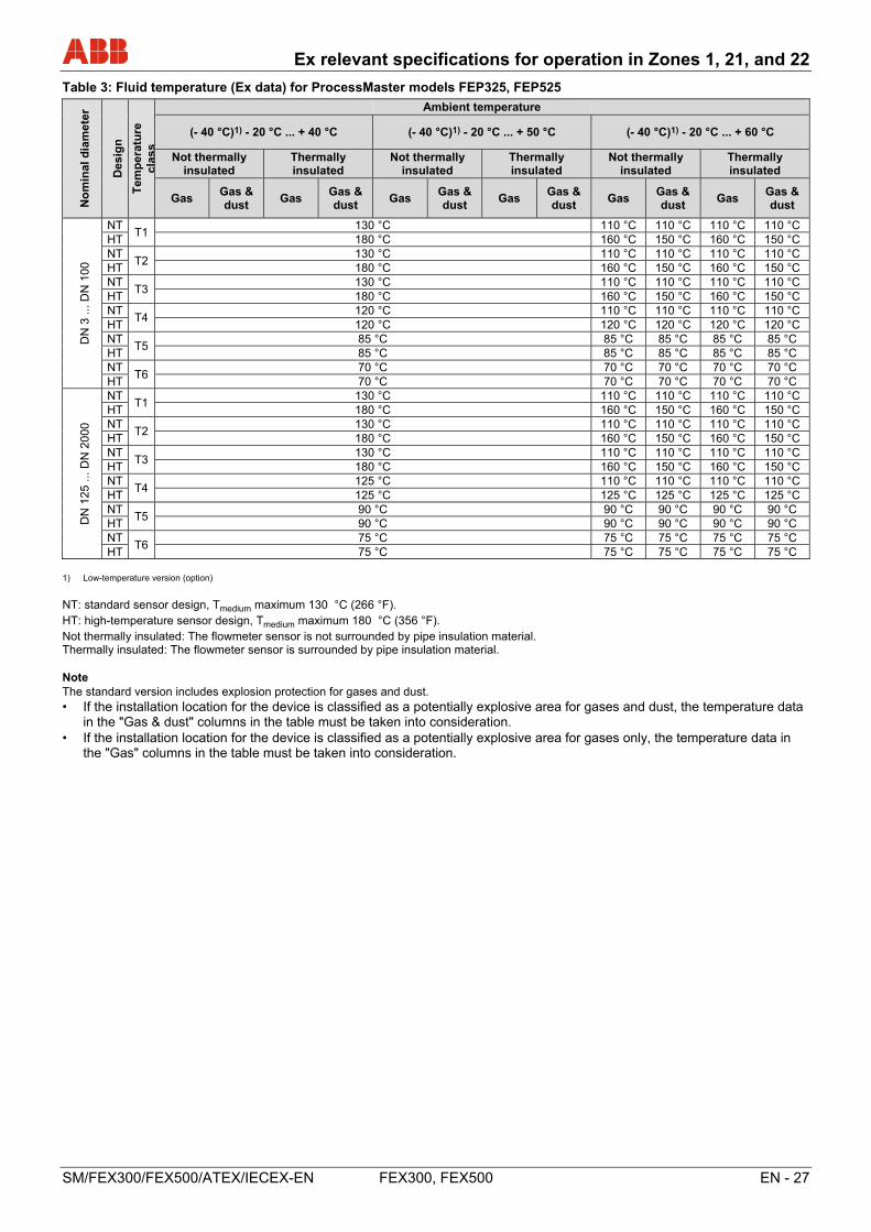
Table 3: Fluid temperature (Ex data) for ProcessMaster models FEP325, FEP525
No
min
al d
iam
ete
r
Des
ign
Tem
per
atu
re
clas
s
Ambient temperature
(- 40 °C)1) - 20 °C ... + 40 °C (- 40 °C)1) - 20 °C ... + 50 °C (- 40 °C)1) - 20 °C ... + 60 °C
Not thermally insulated
Thermally insulated
Not thermally insulated
Thermally insulated
Not thermally insulated
Thermally insulated
Gas Gas & dust
Gas Gas & dust
Gas Gas & dust
Gas Gas & dust
Gas Gas & dust
Gas Gas & dust
DN
3 ..
. DN
100
NT T1
130 °C 110 °C 110 °C 110 °C 110 °C HT 180 °C 160 °C 150 °C 160 °C 150 °C NT
T2 130 °C 110 °C 110 °C 110 °C 110 °C
HT 180 °C 160 °C 150 °C 160 °C 150 °C NT
T3 130 °C 110 °C 110 °C 110 °C 110 °C
HT 180 °C 160 °C 150 °C 160 °C 150 °C NT
T4 120 °C 110 °C 110 °C 110 °C 110 °C
HT 120 °C 120 °C 120 °C 120 °C 120 °C NT
T5 85 °C 85 °C 85 °C 85 °C 85 °C
HT 85 °C 85 °C 85 °C 85 °C 85 °C NT
T6 70 °C 70 °C 70 °C 70 °C 70 °C
HT 70 °C 70 °C 70 °C 70 °C 70 °C
DN
125
...
DN
20
00
NT T1
130 °C 110 °C 110 °C 110 °C 110 °C HT 180 °C 160 °C 150 °C 160 °C 150 °C NT
T2 130 °C 110 °C 110 °C 110 °C 110 °C
HT 180 °C 160 °C 150 °C 160 °C 150 °C NT
T3 130 °C 110 °C 110 °C 110 °C 110 °C
HT 180 °C 160 °C 150 °C 160 °C 150 °C NT
T4 125 °C 110 °C 110 °C 110 °C 110 °C
HT 125 °C 125 °C 125 °C 125 °C 125 °C NT
T5 90 °C 90 °C 90 °C 90 °C 90 °C
HT 90 °C 90 °C 90 °C 90 °C 90 °C NT
T6 75 °C 75 °C 75 °C 75 °C 75 °C
HT 75 °C 75 °C 75 °C 75 °C 75 °C 1) Low-temperature version (option)
NT: standard sensor design, Tmedium maximum 130 °C (266 °F). HT: high-temperature sensor design, Tmedium maximum 180 °C (356 °F). Not thermally insulated: The flowmeter sensor is not surrounded by pipe insulation material. Thermally insulated: The flowmeter sensor is surrounded by pipe insulation material. Note The standard version includes explosion protection for gases and dust. • If the installation location for the device is classified as a potentially explosive area for gases and dust, the temperature data
in the "Gas & dust" columns in the table must be taken into consideration. • If the installation location for the device is classified as a potentially explosive area for gases only, the temperature data in
the "Gas" columns in the table must be taken into consideration.
Ex relevant specifications for operation in Zones 1, 21, and 22
28 - EN FEX300, FEX500 SM/FEX300/FEX500/ATEX/IECEX-EN
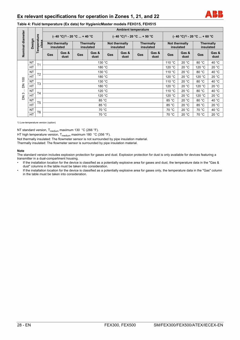
Table 4: Fluid temperature (Ex data) for HygienicMaster models FEH315, FEH515
No
min
al d
iam
ete
r
Des
ign
Tem
per
atu
re
clas
s
Ambient temperature
(- 40 °C)1) - 20 °C ... + 40 °C (- 40 °C)1) - 20 °C ... + 50 °C (- 40 °C)1) - 20 °C ... + 60 °C
Not thermally insulated
Thermally insulated
Not thermally insulated
Thermally insulated
Not thermally insulated
Thermally insulated
Gas Gas & dust
Gas Gas & dust
Gas Gas & dust
Gas Gas & dust
Gas Gas & dust
Gas Gas & dust
DN
3 ..
. DN
100
NT T1
130 °C 110 °C 20 °C 80 °C 40 °C
HT 180 °C 120 °C 20 °C 120 °C 20 °C
NT T2
130 °C 110 °C 20 °C 80 °C 40 °C
HT 180 °C 120 °C 20 °C 120 °C 20 °C
NT T3
130 °C 110 °C 20 °C 80 °C 40 °C
HT 180 °C 120 °C 20 °C 120 °C 20 °C
NT T4
120 °C 110 °C 20 °C 80 °C 40 °C
HT 120 °C 120 °C 20 °C 120 °C 20 °C
NT T5
85 °C 85 °C 20 °C 80 °C 40 °C
HT 85 °C 85 °C 20 °C 85 °C 20 °C
NT T6
70 °C 70 °C 20 °C 70 °C 40 °C
HT 70 °C 70 °C 20 °C 70 °C 20 °C
1) Low-temperature version (option)
NT standard version, Tmedium maximum 130 °C (266 °F).
HT high temperature version, Tmedium maximum 180 °C (356 °F).
Not thermally insulated: The flowmeter sensor is not surrounded by pipe insulation material. Thermally insulated: The flowmeter sensor is surrounded by pipe insulation material. Note The standard version includes explosion protection for gases and dust. Explosion protection for dust is only available for devices featuring a transmitter in a dual-compartment housing. • If the installation location for the device is classified as a potentially explosive area for gases and dust, the temperature data in the "Gas &
dust" columns in the table must be taken into consideration. • If the installation location for the device is classified as a potentially explosive area for gases only, the temperature data in the "Gas" column
in the table must be taken into consideration.

Ex relevant specifications for operation in zones 2, 21 and 22
SM/FEX300/FEX500/ATEX/IECEX-EN FEX300, FEX500 EN - 29
5 Ex relevant specifications for operation in zones 2, 21 and 22
5.1 Electrical connection
5.1.1 Flowmeter sensor and transmitter in zone 2, or transmitter outside the hazardous area
FEP315 / FEP515, FEH315 / FEH515, FEP325 / FEP525, FEH325 / FEH525 flowmeter sensors and FET325 / FET525 transmitters (Zone 2)
FET321 / FET521 transmitter outside the hazardous area
A = Transmitter, B= Sensor
Fig. 14: HART, PROFIBUS PA and FOUNDATION fieldbus protocol Change from one to two columns
Power supply connections
AC power supply Terminal Function / Notes L Live / Phase N Neutral PE / Protective earth (PE)
DC power supply Terminal Function / Notes 1+ + 2- - PE / Protective earth (PE)
Sensor cable terminal connections Only on remote mount design.
Terminal Function / Notes Wire color M1 Magnet coil Brown M2 Magnet coil Red D1 Data line Orange D2 Data line Yellow
/ SE Shield -
E1 Signal line Violet
1S Schield for E1 -
E2 Signal line Blue
2S Schield for E2 -
3 Measurement potential Green
Output connections
Terminal Function / Notes 31 / 32 Current / HART output
The current output is available in "active" or "passive" mode.
97 / 98 Digital communication PROFIBUS PA (PA+ / PA-) or FOUNDATION fieldbus (FF+ / FF-) in acc. with IEC 61158-2.
51 / 52 Digital output DO1 active / passive Function can be configured locally as „Pulse Output" or „Digital Output". Factory setting is „Pulse Output".
81 / 82 Digital input / contact input Function can be configured locally as „External output switch-off“, „external totalizer reset“, „external totalizer stop“ or „other“.
41 / 42 Digital output DO2 passive Function can be configured locally as „Pulse Output" or „Digital Output". Factory setting is „Digital Output", flow direction signaling.
PA Potential Equalization (PA)
Functional ground (only for transmitter outside the hazardous area)
Note The housing for the transmitter and flowmeter sensor must be connected to the potential equalization PA. The operator must ensure that when connecting the protective conductor (PE) no potential differences can occur between protective conductor and potential equalization (PA).
A temperature of 70 °C (158 °F) at the cable entry is assumed for the Ex calculations. Therefore, the cables used for the supply power and the signal inputs and outputs must have a minimum specification of 70 °C (158 °F).
Change from one to two columns
G00873-02
PA
31 32
A
24 V
51 52 81 82 41 42
L N
1+ 2-
M1 M2 D1 D2 3 2S E2 E1 1S
M1 M2 D1 D2 3 E2 E1B
PE
PA
97 98 41 42
PA+ PA-
FF+ FF-
+ -
+ - + - + - + -
HART
PROFIBUS PA, FOUNDATION fieldbus
PA /
2S 1S
PA
PA
PA
FEP315 /FEP515
FEP325 / FEP525FEH325 / FEH525 FET325 / FET525 FET321 / FET521
PA
FEH315 /FEH515
Ex relevant specifications for operation in zones 2, 21 and 22
30 - EN FEX300, FEX500 SM/FEX300/FEX500/ATEX/IECEX-EN
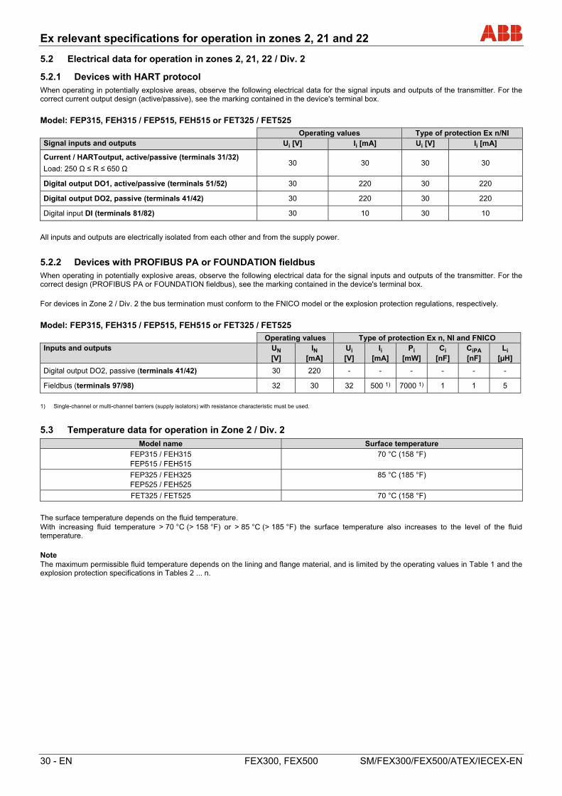
5.2 Electrical data for operation in zones 2, 21, 22 / Div. 2
5.2.1 Devices with HART protocol
When operating in potentially explosive areas, observe the following electrical data for the signal inputs and outputs of the transmitter. For the correct current output design (active/passive), see the marking contained in the device's terminal box.
Model: FEP315, FEH315 / FEP515, FEH515 or FET325 / FET525
Operating values Type of protection Ex n/NI Signal inputs and outputs Ui [V] Ii [mA] Ui [V] Ii [mA]
Current / HARToutput, active/passive (terminals 31/32)
Load: 250 Ω ≤ R ≤ 650 Ω 30 30 30 30
Digital output DO1, active/passive (terminals 51/52) 30 220 30 220
Digital output DO2, passive (terminals 41/42) 30 220 30 220
Digital input DI (terminals 81/82) 30 10 30 10 All inputs and outputs are electrically isolated from each other and from the supply power.
5.2.2 Devices with PROFIBUS PA or FOUNDATION fieldbus
When operating in potentially explosive areas, observe the following electrical data for the signal inputs and outputs of the transmitter. For the correct design (PROFIBUS PA or FOUNDATION fieldbus), see the marking contained in the device's terminal box.
For devices in Zone 2 / Div. 2 the bus termination must conform to the FNICO model or the explosion protection regulations, respectively.
Model: FEP315, FEH315 / FEP515, FEH515 or FET325 / FET525
Operating values Type of protection Ex n, NI and FNICO Inputs and outputs UN
[V] IN
[mA] Ui [V]
Ii [mA]
Pi [mW]
Ci [nF]
CiPA [nF]
Li [µH]
Digital output DO2, passive (terminals 41/42) 30 220 - - - - - -
Fieldbus (terminals 97/98) 32 30 32 500 1) 7000 1) 1 1 5
1) Single-channel or multi-channel barriers (supply isolators) with resistance characteristic must be used.
5.3 Temperature data for operation in Zone 2 / Div. 2
Model name Surface temperature
FEP315 / FEH315 FEP515 / FEH515
70 °C (158 °F)
FEP325 / FEH325 FEP525 / FEH525
85 °C (185 °F)
FET325 / FET525 70 °C (158 °F)
The surface temperature depends on the fluid temperature. With increasing fluid temperature > 70 °C (> 158 °F) or > 85 °C (> 185 °F) the surface temperature also increases to the level of the fluid temperature.
Note The maximum permissible fluid temperature depends on the lining and flange material, and is limited by the operating values in Table 1 and the explosion protection specifications in Tables 2 ... n.
Ex relevant specifications for operation in zones 2, 21 and 22
SM/FEX300/FEX500/ATEX/IECEX-EN FEX300, FEX500 EN - 31
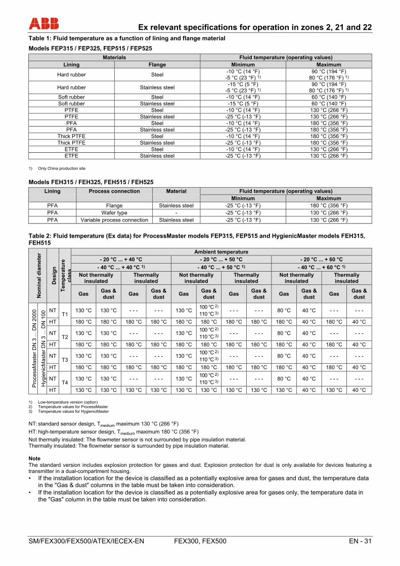
Table 1: Fluid temperature as a function of lining and flange material
Models FEP315 / FEP325, FEP515 / FEP525
Materials Fluid temperature (operating values) Lining Flange Minimum Maximum
Hard rubber Steel -10 °C (14 °F) -5 °C (23 °F) 1)
90 °C (194 °F) 80 °C (176 °F) 1)
Hard rubber Stainless steel -15 °C (5 °F)
-5 °C (23 °F) 1) 90 °C (194 °F)
80 °C (176 °F) 1) Soft rubber Steel -10 °C (14 °F) 60 °C (140 °F) Soft rubber Stainless steel -15 °C (5 °F) 60 °C (140 °F)
PTFE Steel -10 °C (14 °F) 130 °C (266 °F) PTFE Stainless steel -25 °C (-13 °F) 130 °C (266 °F) PFA Steel -10 °C (14 °F) 180 °C (356 °F) PFA Stainless steel -25 °C (-13 °F) 180 °C (356 °F)
Thick PTFE Steel -10 °C (14 °F) 180 °C (356 °F) Thick PTFE Stainless steel -25 °C (-13 °F) 180 °C (356 °F)
ETFE Steel -10 °C (14 °F) 130 °C (266 °F) ETFE Stainless steel -25 °C (-13 °F) 130 °C (266 °F)
1) Only China production site
Models FEH315 / FEH325, FEH515 / FEH525
Lining Process connection Material Fluid temperature (operating values) Minimum Maximum
PFA Flange Stainless steel -25 °C (-13 °F) 180 °C (356 °F) PFA Wafer type - -25 °C (-13 °F) 130 °C (266 °F) PFA Variable process connection Stainless steel -25 °C (-13 °F) 130 °C (266 °F)
Table 2: Fluid temperature (Ex data) for ProcessMaster models FEP315, FEP515 and HygienicMaster models FEH315, FEH515
No
min
al d
iam
ete
r
Des
ign
Tem
per
atu
re
clas
s
Ambient temperature
- 20 °C ... + 40 °C - 20 °C ... + 50 °C - 20 °C ... + 60 °C
- 40 °C ... + 40 °C 1) - 40 °C ... + 50 °C 1) - 40 °C ... + 60 °C 1)
Not thermally insulated
Thermally insulated
Not thermally insulated
Thermally insulated
Not thermally insulated
Thermally insulated
Gas Gas & dust
Gas Gas & dust
Gas Gas & dust
Gas Gas & dust
Gas Gas & dust
Gas Gas & dust
Pro
cess
Mas
ter
DN
3 ..
. DN
200
0
Hyg
ieni
cMas
ter
DN
3 ..
. DN
100
NT T1
130 °C 130 °C - - - - - - 130 °C 100 °C 2) 110 °C 3)
- - - - - - 80 °C 40 °C - - - - - -
HT 180 °C 180 °C 180 °C 180 °C 180 °C 180 °C 180 °C 180 °C 180 °C 40 °C 180 °C 40 °C
NT T2
130 °C 130 °C - - - - - - 130 °C 100 °C 2) 110 °C 3)
- - - - - - 80 °C 40 °C - - - - - -
HT 180 °C 180 °C 180 °C 180 °C 180 °C 180 °C 180 °C 180 °C 180 °C 40 °C 180 °C 40 °C
NT T3
130 °C 130 °C - - - - - - 130 °C 100 °C 2) 110 °C 3)
- - - - - - 80 °C 40 °C - - - - - -
HT 180 °C 180 °C 180 °C 180 °C 180 °C 180 °C 180 °C 180 °C 180 °C 40 °C 180 °C 40 °C
NT T4
130 °C 130 °C - - - - - - 130 °C 100 °C 2) 110 °C 3)
- - - - - - 80 °C 40 °C - - - - - -
HT 130 °C 130 °C 130 °C 130 °C 130 °C 130 °C 130 °C 130 °C 130 °C 40 °C 130 °C 40 °C
1) Low-temperature version (option) 2) Temperature values for ProcessMaster 3) Temperature values for HygienicMaster
NT: standard sensor design, Tmedium maximum 130 °C (266 °F)
HT: high-temperature sensor design, Tmedium maximum 180 °C (356 °F)
Not thermally insulated: The flowmeter sensor is not surrounded by pipe insulation material. Thermally insulated: The flowmeter sensor is surrounded by pipe insulation material. Note The standard version includes explosion protection for gases and dust. Explosion protection for dust is only available for devices featuring a transmitter in a dual-compartment housing. • If the installation location for the device is classified as a potentially explosive area for gases and dust, the temperature data
in the "Gas & dust" columns in the table must be taken into consideration. • If the installation location for the device is classified as a potentially explosive area for gases only, the temperature data in
the "Gas" column in the table must be taken into consideration.
Ex relevant specifications for operation in zones 2, 21 and 22
32 - EN FEX300, FEX500 SM/FEX300/FEX500/ATEX/IECEX-EN
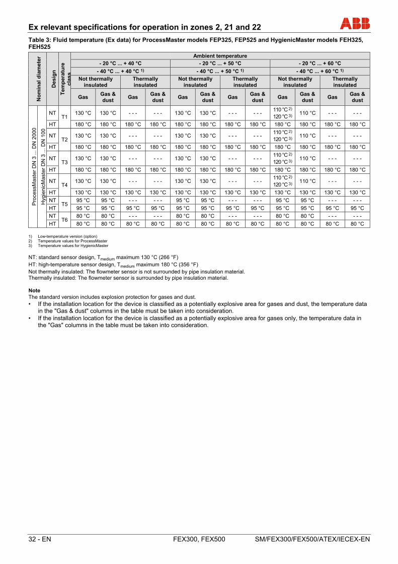
Table 3: Fluid temperature (Ex data) for ProcessMaster models FEP325, FEP525 and HygienicMaster models FEH325, FEH525
No
min
al d
iam
ete
r
Des
ign
Tem
per
atu
re
clas
s
Ambient temperature
- 20 °C ... + 40 °C - 20 °C ... + 50 °C - 20 °C ... + 60 °C
- 40 °C ... + 40 °C 1) - 40 °C ... + 50 °C 1) - 40 °C ... + 60 °C 1)
Not thermally insulated
Thermally insulated
Not thermally insulated
Thermally insulated
Not thermally insulated
Thermally insulated
Gas Gas & dust
Gas Gas & dust
Gas Gas & dust
Gas Gas & dust
Gas Gas & dust
Gas Gas & dust
Pro
cess
Mas
ter
DN
3 ..
. DN
200
0
Hyg
ieni
cMas
ter
DN
3 ..
. DN
100
NT T1
130 °C 130 °C - - - - - - 130 °C 130 °C - - - - - - 110 °C 2) 120 °C 3)
110 °C - - - - - -
HT 180 °C 180 °C 180 °C 180 °C 180 °C 180 °C 180 °C 180 °C 180 °C 180 °C 180 °C 180 °C
NT T2
130 °C 130 °C - - - - - - 130 °C 130 °C - - - - - - 110 °C 2) 120 °C 3)
110 °C - - - - - -
HT 180 °C 180 °C 180 °C 180 °C 180 °C 180 °C 180 °C 180 °C 180 °C 180 °C 180 °C 180 °C
NT T3
130 °C 130 °C - - - - - - 130 °C 130 °C - - - - - - 110 °C 2) 120 °C 3)
110 °C - - - - - -
HT 180 °C 180 °C 180 °C 180 °C 180 °C 180 °C 180 °C 180 °C 180 °C 180 °C 180 °C 180 °C
NT T4
130 °C 130 °C - - - - - - 130 °C 130 °C - - - - - - 110 °C 2) 120 °C 3)
110 °C - - - - - -
HT 130 °C 130 °C 130 °C 130 °C 130 °C 130 °C 130 °C 130 °C 130 °C 130 °C 130 °C 130 °C
NT T5
95 °C 95 °C - - - - - - 95 °C 95 °C - - - - - - 95 °C 95 °C - - - - - -
HT 95 °C 95 °C 95 °C 95 °C 95 °C 95 °C 95 °C 95 °C 95 °C 95 °C 95 °C 95 °C
NT T6
80 °C 80 °C - - - - - - 80 °C 80 °C - - - - - - 80 °C 80 °C - - - - - -
HT 80 °C 80 °C 80 °C 80 °C 80 °C 80 °C 80 °C 80 °C 80 °C 80 °C 80 °C 80 °C 1) Low-temperature version (option) 2) Temperature values for ProcessMaster 3) Temperature values for HygienicMaster
NT: standard sensor design, Tmedium maximum 130 °C (266 °F) HT: high-temperature sensor design, Tmedium maximum 180 °C (356 °F) Not thermally insulated: The flowmeter sensor is not surrounded by pipe insulation material. Thermally insulated: The flowmeter sensor is surrounded by pipe insulation material. Note The standard version includes explosion protection for gases and dust. • If the installation location for the device is classified as a potentially explosive area for gases and dust, the temperature data
in the "Gas & dust" columns in the table must be taken into consideration. • If the installation location for the device is classified as a potentially explosive area for gases only, the temperature data in
the "Gas" columns in the table must be taken into consideration.
Commissioning
SM/FEX300/FEX500/ATEX/IECEX-EN FEX300, FEX500 EN - 33
6 Commissioning
6.1 Preliminary checks prior to start-up
The following points must be checked before commissioning:
• The supply power must be switched off.
• The supply power must match information on the name plate.
• The pin assignment must correspond to the connection diagram.
• Sensor and transmitter must be grounded properly.
• The temperature limits must be observed.
• The sensor must be installed at a largely vibration-free location.
• The housing cover and its safety locking device must be sealed before switching on the supply power.
• For devices with remote mount design and an accuracy of 0.2 % of rate make sure that the flowmeter sensor and the transmitter match correctly. For this purpose, the final characters X1, X2, etc. are printed on the name plates of the flowmeter sensors, whereas the transmitters are identified by the final characters Y1, Y2, etc. Devices with the end characters X1 / Y1 or X2 / Y2, etc. fit with each other.
• Any unused connections must be sealed in accordance with IEC 60079 prior to commissioning using the plugs supplied.
IMPORTANT (NOTE)
Commissioning and operation must be performed in accordance with ATEX 137 or BetrSichV (EN60079-14). Only properly trained personnel are authorized to carry out commissioning in Ex areas.
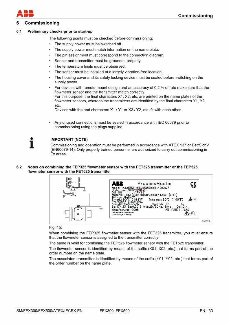
6.2 Notes on combining the FEP325 flowmeter sensor with the FET325 transmitter or the FEP525 flowmeter sensor with the FET525 transmitter
G00875
Fig. 15:
When combining the FEP325 flowmeter sensor with the FET325 transmitter, you must ensure that the flowmeter sensor is assigned to the transmitter correctly.
The same is valid for combining the FEP525 flowmeter sensor with the FET525 transmitter.
The flowmeter sensor is identified by means of the suffix (X01, X02, etc.) that forms part of the order number on the name plate.
The associated transmitter is identified by means of the suffix (Y01, Y02, etc.) that forms part of the order number on the name plate.
Commissioning
34 - EN FEX300, FEX500 SM/FEX300/FEX500/ATEX/IECEX-EN
6.3 Special features of version designed for operation in Ex zone 1 / Div. 1
6.3.1 Configuring the current output
For devices designed for use in Ex Zone 1 / Div.1, the current output cannot be reconfigured subsequently.
The configuration required for the current output (active/passive) must be specified when the order is placed.
For the correct current output design (active/passive), see the marking contained in the device's terminal box.
6.3.2 Configuration of the digital outputs
For version designed for operation in Ex zone 1 / Div. 1, the digital outputs DO1 (51/52) and DO2 (41/42) can be configured on a NAMUR switching amplifier. On leaving the factory, the device is configured with the standard wiring (non-NAMUR).
Devices with PROFIBUS PA or FOUNDATION fieldbus only have the digital output DO2 (41 / 42).
Important (Note)
The outputs' type of protection remains unaffected by this. The devices connected to these outputs must conform to the applicable regulations for explosion protection.
Commissioning
SM/FEX300/FEX500/ATEX/IECEX-EN FEX300, FEX500 EN - 35
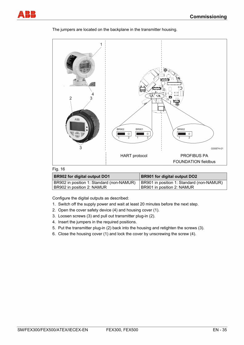
The jumpers are located on the backplane in the transmitter housing.
G00874-01
2 3
3
1
4
1 2 1 2
BR902 BR901
1 2
BR902
HART protocol PROFIBUS PA
FOUNDATION fieldbus
Fig. 16
BR902 for digital output DO1 BR901 for digital output DO2
BR902 in position 1: Standard (non-NAMUR) BR901 in position 1: Standard (non-NAMUR) BR902 in position 2: NAMUR BR901 in position 2: NAMUR
Configure the digital outputs as described:
1. Switch off the supply power and wait at least 20 minutes before the next step.
2. Open the cover safety device (4) and housing cover (1).
3. Loosen screws (3) and pull out transmitter plug-in (2).
4. Insert the jumpers in the required positions.
5. Put the transmitter plug-in (2) back into the housing and retighten the screws (3).
6. Close the housing cover (1) and lock the cover by unscrewing the screw (4).
Commissioning
36 - EN FEX300, FEX500 SM/FEX300/FEX500/ATEX/IECEX-EN
6.4 Changing the type of protection
Models FEP315 / FEP515, FEH315 / FEH515, FEP325 / FEP525, FET325 / FET525 can provide various types of protection during operation:
• When connected to an intrinsically safe circuit in Zone 1, operated as an intrinsically safe device (Ex ia)
• When connected to a non-intrinsically safe circuit in Zone 1, operated as a device with a flameproof enclosure (Ex d)
• When connected to a non-intrinsically safe circuit in Zone 2, operated as a non-sparking device (Ex nA)
If a device which is already operational is required to provide a different type of protection, the following measures must be implemented/insulation checks must be performed in accordance with IEC 60079-ff.
A subsequent change of the type of protection is the sole responsibility of the operator.
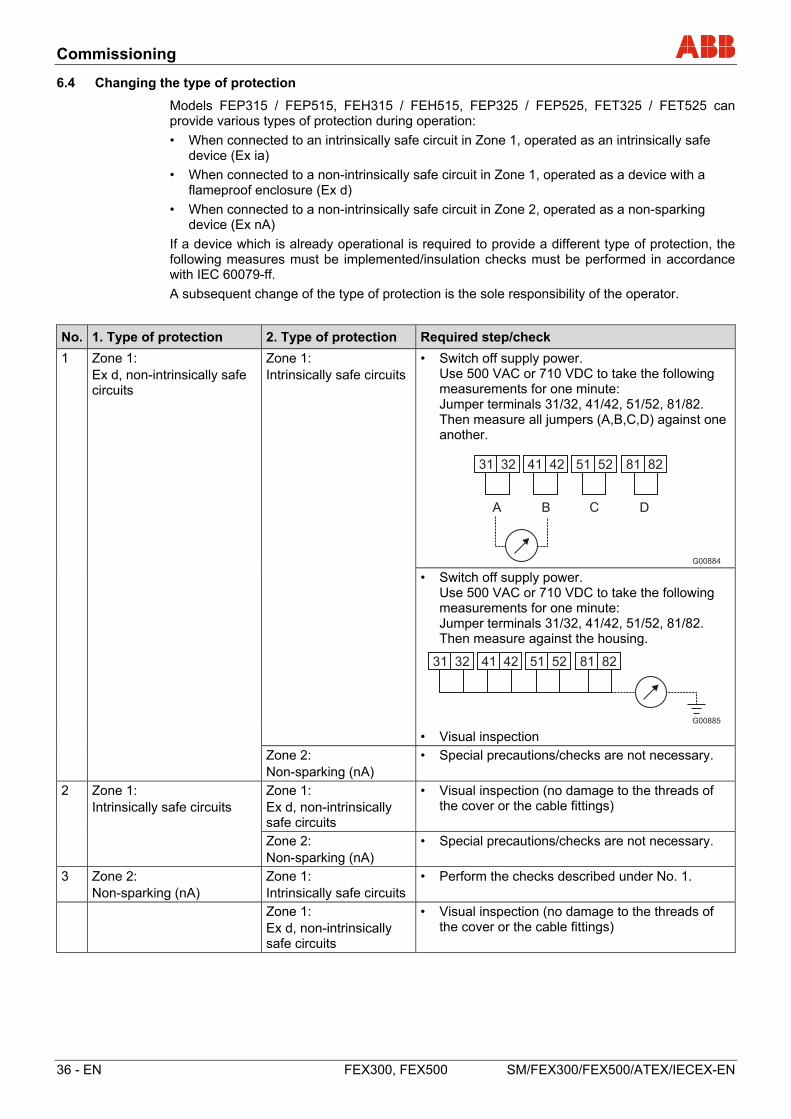
No. 1. Type of protection 2. Type of protection Required step/check
1 Zone 1: Ex d, non-intrinsically safe circuits
Zone 1: Intrinsically safe circuits
• Switch off supply power. Use 500 VAC or 710 VDC to take the following measurements for one minute: Jumper terminals 31/32, 41/42, 51/52, 81/82. Then measure all jumpers (A,B,C,D) against one another.
31 32 41 42 51 52 81 82
A B C D
G00884 • Switch off supply power.
Use 500 VAC or 710 VDC to take the following measurements for one minute: Jumper terminals 31/32, 41/42, 51/52, 81/82. Then measure against the housing.
31 32 41 42 51 52 81 82
G00885 • Visual inspection
Zone 2: Non-sparking (nA)
• Special precautions/checks are not necessary.
2 Zone 1: Intrinsically safe circuits
Zone 1: Ex d, non-intrinsically safe circuits
• Visual inspection (no damage to the threads of the cover or the cable fittings)
Zone 2: Non-sparking (nA)
• Special precautions/checks are not necessary.
3 Zone 2: Non-sparking (nA)
Zone 1: Intrinsically safe circuits
• Perform the checks described under No. 1.
Zone 1: Ex d, non-intrinsically safe circuits
• Visual inspection (no damage to the threads of the cover or the cable fittings)
Maintenance
SM/FEX300/FEX500/ATEX/IECEX-EN FEX300, FEX500 EN - 37
7 Maintenance
7.1 General information
Repair and maintenance activities may only be performed by authorized customer service personnel.
When replacing or repairing individual components, original spare parts must be used.
DANGER - Risk of explosion!
When the housing cover is open, the explosion protection is suspended. Before opening the housing switch off the power to all connection lines and wait at least 20 minutes.
WARNING – Electrical voltage risk!
When the housing is open, EMC protection is impaired and protection against contact is suspended.
Before opening the housing, switch off power to all connecting cables for the device.
NOTICE - Potential damage to parts
The electronic components of the printed circuit board can be damaged by static electricity (observe ESD guidelines).
Make sure that the static electricity in your body is discharged before touching electronic components.
IMPORTANT (NOTE)
Users must also observe the information in the operating and commissioning instruction for the device.
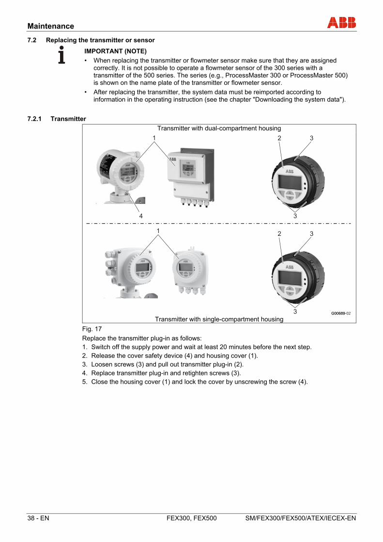
Maintenance
38 - EN FEX300, FEX500 SM/FEX300/FEX500/ATEX/IECEX-EN
7.2 Replacing the transmitter or sensor
IMPORTANT (NOTE)
• When replacing the transmitter or flowmeter sensor make sure that they are assigned correctly. It is not possible to operate a flowmeter sensor of the 300 series with a transmitter of the 500 series. The series (e.g., ProcessMaster 300 or ProcessMaster 500) is shown on the name plate of the transmitter or flowmeter sensor.
• After replacing the transmitter, the system data must be reimported according to information in the operating instruction (see the chapter "Downloading the system data").
7.2.1 Transmitter
Transmitter with dual-compartment housing
Transmitter with single-compartment housing
Fig. 17
Replace the transmitter plug-in as follows: 1. Switch off the supply power and wait at least 20 minutes before the next step.2. Release the cover safety device (4) and housing cover (1). 3. Loosen screws (3) and pull out transmitter plug-in (2). 4. Replace transmitter plug-in and retighten screws (3). 5. Close the housing cover (1) and lock the cover by unscrewing the screw (4).
G00689
2 3
3
1
4
G00689-02
2 3
3
1
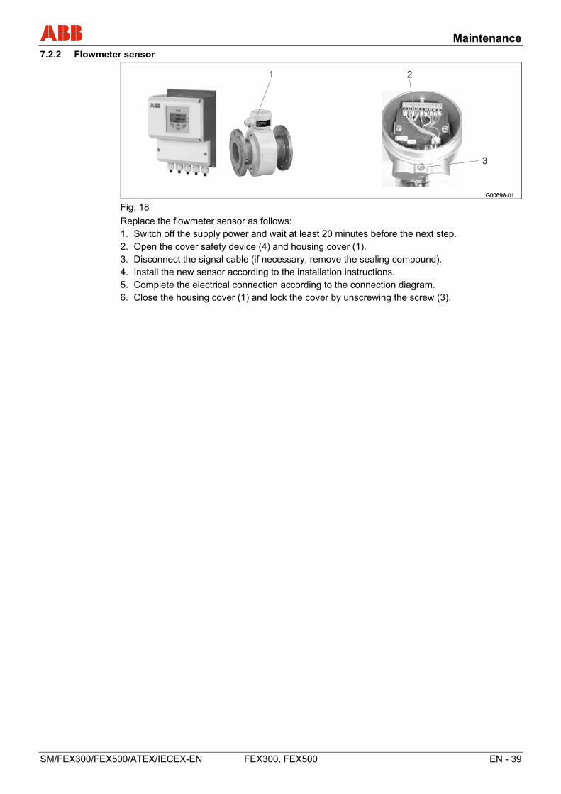
Maintenance
SM/FEX300/FEX500/ATEX/IECEX-EN FEX300, FEX500 EN - 39
7.2.2 Flowmeter sensor
G00698
21
3
G00698-01 Fig. 18
Replace the flowmeter sensor as follows: 1. Switch off the supply power and wait at least 20 minutes before the next step.2. Open the cover safety device (4) and housing cover (1). 3. Disconnect the signal cable (if necessary, remove the sealing compound). 4. Install the new sensor according to the installation instructions. 5. Complete the electrical connection according to the connection diagram. 6. Close the housing cover (1) and lock the cover by unscrewing the screw (3).

Appendix
40 - EN FEX300, FEX500 SM/FEX300/FEX500/ATEX/IECEX-EN
8 Appendix
8.1 Approvals and certifications
CE mark
The version of the meter in your possession meets the requirements of the following European directives:
- EMC directive 2014/30/EU
- Low voltage directive 2014/35/EU
- RoHS Directive 2011/65/EU
- Pressure equipment directive (PED) 2014/68/EU
- ATEX directive 2014/34/EU
Explosion Protection
Identification for intended use in potentially explosive atmospheres according to:
- ATEX directive (marking in addition to CE marking)
- IEC standards
- FM Approvals (US)
- cFM Approvals (Canada)
- NEPSI (China)
- GOST
IMPORTANT (NOTE)
All documentation, declarations of conformity and certificates are available in ABB's download area.
www.abb.com/flow

A
S
M/F
EX
300/
FE
X50
0/A
TE
X/IE
CE
X-E
N
Rev
. D
ABB has Sales & Customer Support expertise in over 100 countries worldwide.
www.abb.com/flow
The Company’s policy is one of continuous product improvement and the right is reserved to modify the
information contained herein without notice.
Printed in the Fed. Rep. of Germany (08.2017)
© ABB 2017
3KXF231300R4801
ABB Limited
Measurement & Analytics
Howard Road, St. Neots
Cambridgeshire, PE19 8EU
UK
Tel: +44 (0) 870 600 6122
Fax: +44 (0)1480 213 339
Mail: [email protected]
ABB Inc.
Measurement & Analytics
125 E. County Line Road
Warminster, PA 18974
USA
Tel: +1 215 674 6000
Fax: +1 215 674 7183
ABB Automation Products GmbH
Measurement & Analytics
Dransfelder Str. 2
37079 Goettingen
Germany
Tel: +49 551 905-0
Fax: +49 551 905-777
Mail: [email protected]
ABB Engineering (Shanghai) Ltd. Measurement & Analytics
No. 4528, Kangxin Highway, Pudong New District
Shanghai, 201319,
P.R. China
Tel: +86(0) 21 6105 6666
Fax: +86(0) 21 6105 6677
Mail: [email protected]