smartplant materials pds interface...
TRANSCRIPT

SmartPlant Materials PDS Interface Configuration
Version 2008 (6.3.1) June 2008 DMAR1-PE-200009H

Copyright Copyright © 2002-2008 Intergraph Corporation. All Rights Reserved.
Including software, file formats, and audiovisual displays; may be used pursuant to applicable software license agreement; contains confidential and proprietary information of Intergraph and/or third parties which is protected by copyright law, trade secret law, and international treaty, and may not be provided or otherwise made available without proper authorization.
Restricted Rights Legend Use, duplication, or disclosure by the government is subject to restrictions as set forth below. For civilian agencies: This was developed at private expense and is “restricted computer software” submitted with restricted rights in accordance with subparagraphs (a) through (d) of the Commercial Computer Software - Restricted Rights clause at 52.227-19 of the Federal Acquisition Regulations (“FAR”) and its successors, and is unpublished and all rights are reserved under the copyright laws of the United States. For units of the Department of Defense (“DoD”): This is “commercial computer software” as defined at DFARS 252.227-7014 and the rights of the Government are as specified at DFARS 227.7202-3. Unpublished – rights reserved under the copyright laws of the United States. Intergraph Corporation Huntsville, Alabama 35894-0001
Warranties and Liabilities All warranties given by Intergraph Corporation about equipment or software are set forth in your purchase contract, and nothing stated in, or implied by, this document or its contents shall be considered or deemed a modification or amendment of such warranties. Intergraph believes the information in this publication is accurate as of its publication date.
The information and the software discussed in this document are subject to change without notice and are subject to applicable technical product descriptions. Intergraph Corporation is not responsible for any error that may appear in this document.
The software discussed in this document is furnished under a license and may be used or copied only in accordance with the terms of this license.
No responsibility is assumed by Intergraph for the use or reliability of software on equipment that is not supplied by Intergraph or its affiliated companies. THE USER OF THE SOFTWARE IS EXPECTED TO MAKE THE FINAL EVALUATION AS TO THE USEFULNESS OF THE SOFTWARE IN HIS OWN ENVIRONMENT.
Intergraph is not responsible for the accuracy of delivered data including, but not limited to, catalog, reference and symbol data. Users should verify for themselves that the data is accurate and suitable for their project work.
Trademarks Intergraph, the Intergraph logo, SmartSketch, FrameWorks, SmartPlant, INtools, MARIAN, PDS, and IntelliShip are registered trademarks of Intergraph Corporation. Microsoft and Windows are registered trademarks of Microsoft Corporation. Other brands and product names are trademarks of their respective owners.

Table of Contents
SmartPlant Materials PDS Interface Configuration 3
Table of Contents Introduction ........................................................................................................................6
Administrative Settings .....................................................................................................7
Transferring Pipe Classes from SmartPlant Materials to PDS .....................................8
PDS Interface Configuration Overview .........................................................................10
General Configuration ....................................................................................................12
Method ........................................................................................................................12 Source .........................................................................................................................12 Company .....................................................................................................................12 Translation Level ........................................................................................................12 Zydex Code .................................................................................................................13 Schedule ......................................................................................................................16 End Preparation ..........................................................................................................18 Table Suffix ................................................................................................................20 Rating ..........................................................................................................................22 Material .......................................................................................................................23 Model Code ................................................................................................................24 Geostandard ................................................................................................................25 Modifier ......................................................................................................................26 Weight Code ...............................................................................................................27 Check Boxes ...............................................................................................................28
S.20.08 Priority ................................................................................................................. 28 Run Procedures ................................................................................................................. 28 Set Def. Atom. .................................................................................................................. 28 Generate CL400 ................................................................................................................ 29
PMC and Codelist Generation ........................................................................................30
PMC Generation General ...........................................................................................30 PMC ASCII Configuration .........................................................................................31
Seq .................................................................................................................................... 31 Default .............................................................................................................................. 31 Title ................................................................................................................................... 31
PMC Items ..................................................................................................................32 Spec Code ......................................................................................................................... 32 Revision ............................................................................................................................ 32 Fluid .................................................................................................................................. 32 Mat of Constr .................................................................................................................... 33 Corr Allow ........................................................................................................................ 33 Mat Desc ........................................................................................................................... 33

Table of Contents
4 SmartPlant Materials PDS Interface Configuration
Press Temp ........................................................................................................................ 33 Nom Size ........................................................................................................................... 34 Thickness .......................................................................................................................... 34 Thick Equot ....................................................................................................................... 34 Branches ............................................................................................................................ 35 TAP ................................................................................................................................... 35 Vent Drain ......................................................................................................................... 35 Gasket ............................................................................................................................... 36 Std Note A ........................................................................................................................ 36 Std Note B ......................................................................................................................... 36 Bend Defl .......................................................................................................................... 37 Pipe Lgth ........................................................................................................................... 37 Shortage ............................................................................................................................ 37 FabCat ............................................................................................................................... 37
Codelist Generation General ......................................................................................38 Settings in PDS 10.01 .................................................................................................40
Wallthick 1 ........................................................................................................................ 40 Wallthick 2 ........................................................................................................................ 40 Size Depending ................................................................................................................. 40 Codelist Generation .......................................................................................................... 41 Short Desc Lib .................................................................................................................. 42 PDS File Names ................................................................................................................ 43 576 Start ............................................................................................................................ 43 577 Start ............................................................................................................................ 43 DIN or ANSI ..................................................................................................................... 43
Viewing and Manipulating Codelists .........................................................................44 Creating Codelists Independently from Specification ................................................45
Available Lists .................................................................................................................. 45 Actions / Settings .............................................................................................................. 47 List Display Area .............................................................................................................. 48
PCD Special Settings (PDS 10.01 / 10.02) ......................................................................50
Settings in PDS 10.01 .................................................................................................50 Order/Sequence ................................................................................................................. 50 Bolt Logic ......................................................................................................................... 50 Dissolve Assemblies ......................................................................................................... 51 Filter .................................................................................................................................. 51 Branch Opt ........................................................................................................................ 52 Gen. Elbows ...................................................................................................................... 52 Sort by CC ........................................................................................................................ 52 Issued Only ....................................................................................................................... 52 Include Tags ...................................................................................................................... 52
Settings in PDS 10.02 .................................................................................................53
Mapping Techniques in S.20.08 ......................................................................................55
Generating PMC/PCD with User-Defined Procedures ................................................57
Defining Procedures ...................................................................................................57

Table of Contents
SmartPlant Materials PDS Interface Configuration 5
Assigning Procedures .................................................................................................59 PMC/PCD Table Structure .........................................................................................59
Generating PDL (Geometrics) for PDS .........................................................................61
Tuning Generated SQL Statements ............................................................................66 Geometric Generation Important Information ............................................................67 Configuring PDL Specials (PDS 10.01) .....................................................................68
Accessing Files on the Web .............................................................................................69
BOM Import Configuration (PDS 30.01) ......................................................................70
Configuration Items ....................................................................................................71 Configuring BOM Report Item ‘Type’ (PDS 30.01) ........................................................ 78
Creating ASCII-File from PDS-3D (piping_g) ..........................................................79 Using the OMI Import Screen for PDS (B 40.01) ......................................................83 Interpreting the “Piping_g” File .................................................................................84 Interpreting the ISOGEN File .....................................................................................85

Introduction
6 SmartPlant Materials PDS Interface Configuration
Introduction The SmartPlant Materials PDS® Interface is configurable and allows users to combine the SmartPlant Materials standardization data in different ways with the additional PDS data. So it is possible to adapt the individual structure of the SmartPlant Materials standardization to make it possible to populate the needed files for PDS that have a fixed structure.
Projects developing the configuration structure require a team that includes PDS and SmartPlant Materials experts.
The SmartPlant Materials experts should be familiar with the SmartPlant Materials Material Life Cycle Library (Standardization)module, the administration module, and the individual standardization structure. The PDS experts should have PDS administration knowledge and should be able to work with the reference data manager. Both should read and understand this guide before configuring the PDS Interface.
Using SmartPlant Materials with PDS makes the creation of new pipe classes and modification of existing pipe classes more efficient, easier, and faster. Additionally, the SmartPlant Materials Material Life Cycle Library (Standardization) module makes it easier to maintain the data and is able to improve the quality of pipe material class data.
Also, SmartPlant Materials is able to transfer the standardization data not only to PDS but also to other competitive CAD systems that are often used in parallel within companies or projects. With SmartPlant Materials interfaces to systems like SAP, it is possible to standardize all process material only once; at the single point of data entry to SmartPlant Materials.

Administrative Settings
SmartPlant Materials PDS Interface Configuration 7
Administrative Settings The SmartPlant Materials users who are working with the PDS Interface must have the role INTERFACE. They only need to be assigned to this role. The login should always be done with any other role, for example, PUBLIC.
The PDS Interface must be assigned in screen A70.01, which is only possible if the user has the role interface.

Transferring Pipe Classes from SmartPlant Materials to PDS
8 SmartPlant Materials PDS Interface Configuration
Transferring Pipe Classes from SmartPlant Materials to PDS
The first steps of transferring data from SmartPlant Materials to PDS® involve pipe classes. Unlike SmartPlant Materials in which the pipe classes are the result of primary standardization work (Commodity Group, Commodity Part, Commodity Tables, Commodity Code, Geometrics, Idents, Pipe Class), in PDS the definition of components may be done at first within the pipe classes. The other database objects like model codes, physical data, and so forth may be created later on. So understanding how the interface works means at first to understand the format and concept of the SmartPlant Materials pipe classes and the format of the PDS pipe class.
A SmartPlant Materials pipe class looks like this:

Transferring Pipe Classes from SmartPlant Materials to PDS
SmartPlant Materials PDS Interface Configuration 9
A typical PCD file for PDS looks like this:
The target of the PDS Interface is to create such a PCD file for each SmartPlant Materials pipe class.

PDS Interface Configuration Overview
10 SmartPlant Materials PDS Interface Configuration
PDS Interface Configuration Overview The PDS Interface Configuration has two parts.
• Configuration and creation of pipe class data including pipe material class data code lists, short description library, and so forth
• Configuration and creation of physical data library (PDL, or geometric data)
Each customer may decide according to his needs if he wants to create only the data out of the first, or if he also wants to maintain the geometric data in SmartPlant Materials. If the geometric data is not maintained in SmartPlant Materials, it has to be maintained in PDS. In this case the operation within PDS reference data manager is identical to the normal operation.
Due to the fact that SmartPlant Materials is a high flexible tool, it is not fixed how the customers store their standardization data. So from the SmartPlant Materials point of view the interface should not force SmartPlant Materials to use only one way for standardization, because SmartPlant Materials would loose its flexibility. So all SmartPlant Materials Interfaces that transfer data from SmartPlant Materials standardization to any other IT system are always configurable. The configuration informs the interface about the methods for how the standardization on the actual system has been done and where the certain data values can be found.
The configuration of the first part takes place in screen PDS10.01. This screen consists of the following tab pages:
• general configuration - settings for global values of standardization

PDS Interface Configuration Overview
SmartPlant Materials PDS Interface Configuration 11
• mc specials - piping material class configuration
• pcd specials - piping commodity data configuration
• pdl specials - physical data library configuration
• config of additional files - additional files size depending on data, short desc, and codelists

General Configuration
12 SmartPlant Materials PDS Interface Configuration
General Configuration Method
A method describes how SmartPlant Materials should retrieve values that have to be placed within a PCD or other neutral files. In many cases 'Method' is completed by the entry in 'Source' to specify where the value can be found if a certain method is used. In most of the PDS objects, the methods for how to store the values in SmartPlant Materials are different.
The existing methods vary depending on the values that should be retrieved. The methods are explained in detail within the description of each value.
Source The entry defines where SmartPlant Materials should find a value to put into PCD or other neutral files. The 'Source' depends on the associated 'Method'. For some methods, the value in 'Source' has no effect.
Company It is possible to enter a company-specific mapping for commodity codes in S.30.C.01 and for idents in S.80.C.01, respectively. If these translations are to be placed in the PCD, the code of the company used in S.30.C.01 or S.80.C.01 has to be entered here. If the original SmartPlant Materials-commodity codes shall be transferred to PDS, the company code SmartPlant Materials must be chosen.
Translation Level The translation level works together with the entry in 'Company' and determines whether to have commodity codes and their descriptions in SDL or ident codes with their description. The same logic is applied to SDD. If you set the level to Ident, the PCD will automatically be split, even if you didn't set 'Filter'-Option in PDS.10.01. The source of the CC/Ident always depends on the entry in the Company field of this screen.
Tip
• Refer to the Help text on this field for more details.

General Configuration
SmartPlant Materials PDS Interface Configuration 13
Zydex Code The ZYDEX Code is not mentioned in the Configuration Screen PDS10.01 because the concept of the ZYDEX Code in PDS is equal to the SmartPlant Materials part concept. So it is not necessary choose a different mapping method.
The ZYDEX Code is always mapped with the so-called S20.08 method.
The S20.08 Method may be used for several PDS values, but for the Zydex code it is the only possible way. The Zydex code is stored in a SmartPlant Materials table and then mapped directly to the concerning part code in the screen S20.08.
The creation of a SmartPlant Materials Table takes place in screen A50.02
Table for Zydex Code
Besides the Zydex Code, PDS needs information about the number of nominal diameters that the component has. This information is stored in the variable attribute TD.CHAR1 that is assigned in our example to the AABBCC Table in screen A50.03.
The map name for PDS in A.50.I.01 is ZYDEX. This table is filled with the screen S 20.I.02-03. In screen S 20.I.02 table groups may be created. In most cases this is not necessary, so only one mandatory group has to be created e.g. NONE. You can have more than one table for this purpose. Map additional tables by appending a running number to the map name like <mapname>_1 etc in A.50.I.01.

General Configuration
14 SmartPlant Materials PDS Interface Configuration
In this group all Zydex codes referring the customer to PDS may be created. The variable attribute TD.char1 (NPS2) is filled with * for all components with only one nominal diameter. For the components with two nominal diameters the value must be empty.
The mapping of one SmartPlant Materials part code to one PDS Zydex code is done in screen S20.08 Parts with Interface details. In window 1 the part that should be mapped is selected. In window 2 the mapping takes place by selecting the Zydex code containing table in block 2 and one Zydex code in block 3.
The table detail may be chosen by using the LOV functionality. Now the PDS interface is able to find behind the SmartPlant Materials part code 01 in the commodity group T_PIPE the Zydex Code PIPING. All Commodity Codes based on the SmartPlant Materials pipe class contain one ore more commodity codes which were created with the part group ‘T_PIPE’ and part code ‘01’. All these specification items will have in the pcd-file the ZYDEX Code ‘PIPING.’
Window 2 contains lines with Seq 1 and Seq 2. Seq 1 is for the green end, and Seq 2 for the red end. In addition, you have the possibility to specify more than one mapping per part. Do this by:
1. Entering the table detail for Seq 1 (and Seq 2 if applicable) and change to Window 3. Here you can enter a commodity detail condition which must be true to let this mapping become active. The entries in Window 3 are used in an AND-condition, which means, that all of them must be true to activate the associated mapping in Window 2.

General Configuration
SmartPlant Materials PDS Interface Configuration 15
2. Then enter a second mapping in Window 2 and give another commodity detail combination. As a result, you will have two different PDS values for different commodity codes within the same part.
You can have more than two different mappings.

General Configuration
16 SmartPlant Materials PDS Interface Configuration
Schedule Here you specify the method and source of search for the schedule of the components.
There are two possibilities: S.30.01 (S.20.08)
In the standardization for all parts with a schedule, the schedule is stored in the Commodity Code. If no specific Commodity Code is found, SmartPlant Materials looks for a mapping in S.20.08.
The mapping name in A.50.I.01 must be SCHEDULE for the green connect point and ASCHEDULE for the red connect point. You can have more than one table for this purpose. Map additional tables by appending a running number to the map name like <mapname>_1 and so on in A.50.I.01.
If the mentioned table is not directly a table in the Commodity Code but a master link table of the Commodity Code that contains this table as a link table, the PDS Interface will also be able to find the information.
For the method via S. 30.01 (S.20.08) you must indicate from where the Schedule shall be read.
The following possibilities exist:
• Table Detail - value in TD Code is taken
• S. 20.I.01 - translated value from S.20.I.01 is taken
• ATTR_CHAR1 - value of ATTR_CHAR1 is taken
• ATTR_CHAR2 - value of ATTR_CHAR2 is taken
• ATTR_CHAR3 - value of ATTR_CHAR3 is taken

General Configuration
SmartPlant Materials PDS Interface Configuration 17
• ATTR_NUM1 - value of ATTR_NUM1 is taken
• ATTR_NUM2 - value of ATTR_NUM2 is taken
• ATTR_NUM3 - value of ATTR_NUM3 is taken
Geoms In this case the schedule is not found in the commodity code but always in the geometric tables related to the commodity code.
The attribute containing the schedule has to be marked in the object parameter as building ident, and it has to be an Input Field.
Schedules are set only for pipes from Geom. Therefore, the Nominal Sizes of the pipes are split automatically, even if the check box Filters is not selected. Material which is split in the PMC file occurs with one row for each dimension of the commodity code. This is necessary because the Schedule can be different per each Nominal Size.
For all components which are not Pipes, the schedule assignment is carried out via S.20.08.
For all these components the mapped values can be NREQ ( not required) for parts without schedule or MATCH. In case of MATCH, the schedule of the Pipe will be copied to the non pipe component ( PDS functionality).
Furthermore, you have to enter the attribute which contains the Schedule for Ident (See 'Schedule Attribute'). The attribute that you select from LOV has to correspond to the one you have assigned to Ident in Object Parameter Details.
The Schedule in PCD is changed the following:
• $.375 translates into .375
• S$40 translates into S-40

General Configuration
18 SmartPlant Materials PDS Interface Configuration
End Preparation For the end preparation, the interface does not offer different methods. The PDS conform method for standardizing the end preparation is in the commodity code or in S20.08.
The software searches for the end preparation first in the Commodity Code; if it is not found, the program searches for a mapping in S.20.08. If it is also not found in S20.08, the end preparation will not be found.
If the information concerning the end preparation is stored in a linked table, the PDS Interface will also be able to find the information as long as the translation in A.50.I.01 is made.
The map name in A.50.I.01 must be CL330. You can also have the RED and the GREEN end connection in one Table. To do so, it is necessary to use another attribute (e.g. ATTR_CHAR3) where you want to define the RED-Connect point. The place of the attribute is not important, but the name must be ACL330. If such an Attribute is found in the table which is translated with CL330 in A.50.I.01, the value of this Attribute will be used to fill in the Red-Connect point of PCD.
For some components (e.g. flanges), it may be required that the end connection has to be stored in another table than the one mapped with CL330 in A.50.I.01. In such a case, you can define a translation for another end connection table in A.50.I.01 which is called CL330_1. If the Commodity Code Detail or the linked table of Commodity Code Details contains a Table which is translated with CL330_1, it will be used prior to the one mapped with CL330.
PDS-Interface will then pick up the Green Connection from the Table mapped with CL330_1. It will take the Attribute with the Name CL330 on this table. The place does not matter.
The Red Connection will be picked up from the Table mapped with CL330 from Attribute CL330. Also, here the name of the Attribute is important, not the place.
You must enter into 'Source' the attribute of the table in which the PDS end preparation number can be found for the green end and for the red end, if they exist.
The following possibilities exist:
• Table Detail - value in TD Code is taken
• S. 20.I.01 - translated value from S.20.I.01 is taken
• ATTR_CHAR1 - value of ATTR_CHAR1 is taken
• ATTR_CHAR2 - value of ATTR_CHAR2 is taken
• ATTR_CHAR3 - value of ATTR_CHAR3 is taken

General Configuration
SmartPlant Materials PDS Interface Configuration 19
• ATTR_NUM1 - value of ATTR_NUM1 is taken
• ATTR_NUM2 - value of ATTR_NUM2 is taken
• ATTR_NUM3 - value of ATTR_NUM3 is taken
Additionally, the connect group must be entered into the table for the end preparation at any variable attribute. The connect group is a value that is used for the generation of the physical data file name . So it is information that is not necessary for the PCD generation, but only for the geometric data.
The field Connect Group contains connect group information.
1. If we have two endprep tables, the connect group for red and green end is simply looked up on the attribute defined in the PDS 10.01 configuration screen.
2. If we have one endprep table, green end works as under 1), but there is no place to define a second connect group. The red connect group is looked up the following way:
1. Find the end prep for red end: For example, table detail "AR" in the table "EXT" - "Butwelding - Socketwelding Female" red endprep is "421". The green endprep is "301" and the green connect group is "300".
2. Find a connect group for endprep "421": Table detail "RR" - "Socket Welding female" has green endprep "421", so take the associated connect group "420" for our red connect group.
If we have endpreps, which only occur for red end, we would have to define the endprep values which are used for the red end in a special way:
3. Insert a new table detail record in S.20.02 in the same table/table group with an arbitrary table detail code.
4. Assign the red endprep in this record ON THE FIELD OF THE GREEN ENDPREP.
5. Assign as well the connect group for the red endprep on the connect group field (where normally the green connect group is situated).
You will never use this table detail in any of your commodity codes. It is just used to find an appropriate red connect group.

General Configuration
20 SmartPlant Materials PDS Interface Configuration
Table Suffix Here is the method for finding the table suffix data. The following methods are available.
• Geom ID
Selecting the method Geom ID means that the internal SmartPlant Materials ID of the geometry (see S.50.06 GEOM) which is used in S50.06 in the fields geom 1 and 2 serves as Table Suffix for the Commodity Code. The Geom ID is a number value, which may reach values > 9999.
With this, Geom1 is considered as Table Suffix Green and Geom2 as Table Suffix Red.
• Geom S.40.I.01
The values of Geom1, or Geom2 respectively in S.50.06 are the basis for the Table Suffix. A translation from S.40.I.01 is taken here instead of the internal MAR IAN ID. In this case, the initial value in PDS.10.01 will be neglected. If a component has only one geometry in its specification but needs two Table Suffixes like for a pre-welding flange, you may assign two Table Suffixes to one geometry as Green and Red Connect Points. Enter the second Table Suffix into the field named File Name.
• S.20.08
For this method, the Mapping Name for the SmartPlant Materials table in A.50.I.01 must be called TS.
For the method via S. 20.08 it has to be indicated in 'Source' from which variable attribute the Table Suffix shall be read in the mapped table.
The following possibilities exist:
• Table Detail - value in TD Code is taken • S. 20.I.01 - translated value from S.20.I.01 is taken • ATTR_CHAR1 - value of ATTR_CHAR1 is taken • ATTR_CHAR2 - value of ATTR_CHAR2 is taken • ATTR_CHAR3 - value of ATTR_CHAR3 is taken • ATTR_NUM1 - value of ATTR_NUM1 is taken • ATTR_NUM2 - value of ATTR_NUM2 is taken • ATTR_NUM3 - value of ATTR_NUM3 is taken

General Configuration
SmartPlant Materials PDS Interface Configuration 21
• CCG Relation
Tablesuffix can be found in Geometrics that are assigned to the Commodity Code in M_COMMODITY_GEOMETRIC_RELATION. If more than one geometric is assigned to CC, the first one will be taken, because we assume that if more than one Geometric is assigned whether the TS is the same or only one will have a TS.
Because this screen can also be used for other Interfaces, the column headers do not fit directly to the PDS Interface. The Field Interface Gn Code will contain the Tablesuffix green and the field File name will contain the Tablesuffix red. This translation has to be done for each geometric that has a geometric relation to a commodity code used in a PDS pipe spec.

General Configuration
22 SmartPlant Materials PDS Interface Configuration
Rating Like the end preparation, the interface offers two different methods for selecting the rating of a component, but these methods cannot be selected in all cases. The rating is contained in the Commodity Code. If the system does not find the rating within the commodity code, the S20.08 method is automatically used.
The map name for the SmartPlant Materials table in A.50.I.01 must be RATING for the green, or ARATING for the red connect point. You can have more than one table for this purpose. Map additional tables by appending an running number to the mapname like <mapname>_1 etc in A.50.I.01. If the Commodity Code contains a link table the PDS Interface will also be able to find information in the linked table as long as the translation in A.50.I.01 is made. You must enter into 'Source' the attribute of the mapped SmartPlant Materials table in which the PDS Rating value can be found for the green and the red connect point.
The following possibilities exist:
• Table Detail - value in TD Code is taken
• S. 20.I.01 - translated value from S.20.I.01 is taken
• ATTR_CHAR1 - value of ATTR_CHAR1 is taken
• ATTR_CHAR2 - value of ATTR_CHAR2 is taken
• ATTR_CHAR3 - value of ATTR_CHAR3 is taken
• ATTR_NUM1 - value of ATTR_NUM1 is taken
• ATTR_NUM2 - value of ATTR_NUM2 is taken
• ATTR_NUM3 - value of ATTR_NUM3 is taken
The PCD Ratings begin with the prefix CL if ANSI applies, e.g. CL300. The name for the PDS geometry is only 300, however. If DIN applies, the class has to be followed by a "#".
We suggest that users enter the tables for the Ratings without the CL or "#" and append the CL or "#" in PCD via procedure.
General Configuration
SmartPlant Materials PDS Interface Configuration 23
Material For the material there is again only one possible method; it must be contained in the commodity code.
You can define more than one SmartPlant Materials table containing the Material. Of course only one of these tables shall be part of one Commodity Code. So you can build up Material Tables for items such as Flange Material and Pipe Material. To identify these SmartPlant Materials tables for the PDS interface in A.50.I.01, use translation CL145_1, CL_145_2, etc. - or if you use just one table: CL145. If the Commodity Code contains a link table, PDS Interface will also be able to find information in the linked table as long as the translation in A.50.I.01 is made.
You must enter into 'Source' the attribute of the table in which the PDS material number can be found.
The following possibilities exist:
• Table Detail - value in TD Code is taken
• S. 20.I.01 - translated value from S.20.I.01 is taken
• ATTR_CHAR1 - value of ATTR_CHAR1 is taken
• ATTR_CHAR2 - value of ATTR_CHAR2 is taken
• ATTR_CHAR3 - value of ATTR_CHAR3 is taken
• ATTR_NUM1 - value of ATTR_NUM1 is taken
• ATTR_NUM2 - value of ATTR_NUM2 is taken
• ATTR_NUM3 - value of ATTR_NUM3 is taken
General Configuration
24 SmartPlant Materials PDS Interface Configuration
Model Code Here you specify the method and source of search for the Model Code of the components.
There are the following possibilities:
• Method Part Name - Part Name means that the Model Code produced for PDS is identical with the SmartPlant Materials Part Name in S.10.03. No further mapping or data entry is necessary if this method is used.
• Method S.20.08 - S.20.08 means that for every SmartPlant Materials part a Model Code has to be mapped in module S.20.08. To identify the SmartPlant Materials table for the PDS interface in A.50.I.01, use translation MODEL. You can have more than one table for this purpose. Map additional tables by appending an running number to the mapname like <mapname>_1 etc in A.50.I.01.
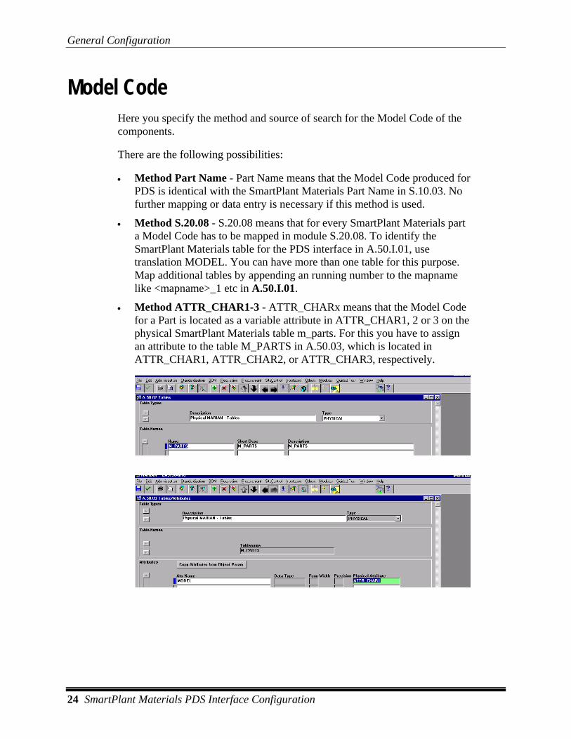
• Method ATTR_CHAR1-3 - ATTR_CHARx means that the Model Code for a Part is located as a variable attribute in ATTR_CHAR1, 2 or 3 on the physical SmartPlant Materials table m_parts. For this you have to assign an attribute to the table M_PARTS in A.50.03, which is located in ATTR_CHAR1, ATTR_CHAR2, or ATTR_CHAR3, respectively.

General Configuration
SmartPlant Materials PDS Interface Configuration 25
Geostandard Here you specify how SmartPlant Materials shall look for Geostandard. There are the following possibilities:
• S.30.01 - Using this method the PDS Interface will search the Geostandard in the Commodity code tables. The mapname for the SmartPlant Materials table in A50.I.01 has to be identified by CL575. You can have more than one table for this purpose. Map additional tables by appending an running number to the mapname like <mapname>_1 etc in A.50.I.01.
• S.20.08 - S.20.08 means that for every SmartPlant Materials part a Geostandard has to be mapped in module S.20.08. To identify the SmartPlant Materials table for the PDS interface in A.50.I.01, use translation CL575. You can have more than one table for this purpose. Map additional tables by appending an running number to the mapname like <mapname>_1 etc in A.50.I.01.
• Table Detail ID - The Geostandard is in the Commodity Code, and the internal Table Detail ID - which is invisible on the screens - is taken. The value in '575Start' can be used as an additive value. 575 Start is an additive value if you use the method 'Table Detail ID' or 'Function' for Geostandard. Look for help on 'Geostandard'.
For the method via S.30.01, S.20.08 you must enter into 'Source' the attribute from which the Geostandard shall be read.
The following possibilities exist for both methods:
• Table Detail - value in TD Code is taken
• S. 20.I.01 - translated value from S.20.I.01 is taken
• ATTR_CHAR1 - value of ATTR_CHAR1 is taken
• ATTR_CHAR2 - value of ATTR_CHAR2 is taken
• ATTR_CHAR3 - value of ATTR_CHAR3 is taken
• ATTR_NUM1 - value of ATTR_NUM1 is taken
• ATTR_NUM2 - value of ATTR_NUM2 is taken
• ATTR_NUM3 - value of ATTR_NUM3 is taken

General Configuration
26 SmartPlant Materials PDS Interface Configuration
Modifier The software searches for the modifier first in the Commodity Code; if it is not found, the program searches for a mapping in S.20.08.
The mapname for the SmartPlant Materials table in A50.I.01 has to be identified by CL550. You can have more than one table for this purpose. Map additional tables by appending an running number to the mapname like <mapname>_1 etc in A.50.I.01.
If your Commodity Code contains a link table, the PDS Interface will also be able to find information in the linked table as long as the translation in A.50.I.01 is made.
You must enter the variable attribute of the SmartPlant Materials table in which the PDS Modifier can be found.
The following possibilities exist:
• Table Detail - value in TD Code is taken
• S. 20.I.01 - translated value from S.20.I.01 is taken
• ATTR_CHAR1 - value of ATTR_CHAR1 is taken
• ATTR_CHAR2 - value of ATTR_CHAR2 is taken
• ATTR_CHAR3 - value of ATTR_CHAR3 is taken
• ATTR_NUM1 - value of ATTR_NUM1 is taken
• ATTR_NUM2 - value of ATTR_NUM2 is taken
• ATTR_NUM3 - value of ATTR_NUM3 is taken

General Configuration
SmartPlant Materials PDS Interface Configuration 27
Weight Code The Map Name in A.50.I.01 must be CL578. You can have more than one table for this purpose. Map additional tables by appending an running number to the mapname like <mapname>_1 etc in A.50.I.01. The codelist value must be written in TD_CODE. The value in Weight Code in PDS.10.01 indicates in which attribute of the Weight Code Table the real specific weight is written. If the CL value CL578 for the Weight Code is written in the Material Table, it is identical to the attribute for the specific weight in CL578.
In Material, the Weight Code is stored in the same SmartPlant Materials table as the material that is mapped as described in the previous section titled Material on page 23.
In Source, the variable attribute of the SmartPlant Materials material table is defined. This attribute is where the PDS Weight Code can be found.
S.20.08 means that the Weight Code is assigned via method S.20.08. The Map Name for the SmartPlant Materials weight code table in A.50.I.01 must be CL578.
In Linking, the Weight Code is added to the material table via table linking. Like the method in Material, in this case no mapping in A.50.I.01 has to be made, because the interface will follow the mapping for the material. See the section titled Material on page 23.

General Configuration
28 SmartPlant Materials PDS Interface Configuration
Check Boxes
S.20.08 Priority If this box is selected, the values are first taken from S.20.08. If not found, the values are taken from Commodity Codes. This check box is only useful if for several Commodity Codes definitions exist both directly in the commodity code and in S20.08. S20.08 should have priority.
Run Procedures Run Procedures defined in PDS 10.03 automatically after the PMC/PCD-creation in PDS 10.12 (Yes if checked)?
Set Def. Atom. Set default value automatically when value not found? This applies to PCD-generation. The associated defaults are definable in PDS 10.02. See also Settings in PDS 10.02 on page 53.

General Configuration
SmartPlant Materials PDS Interface Configuration 29
Generate CL400 The following possibilities exist:
1. Automatic generation of codelist 400 (checked). For every Option Code entry into the pipe classes in SmartPlant Materials which differs from 1, another entry is generated in CL400 following the pattern: Commodity ID = Commodity Code Short Description In the PCD file, the Option Code is replaced by Commodity ID for all options not equal to 1. If the translation level is set to "Ident" level and the company is not "SmartPlant Materials," then the option will be set to the ident instead of the commodity id.
2. Manual editing of codelist 400 (unchecked). The values of the Option Code are transferred from the spec items into the PCD file. Code list 400 is edited manually in SmartPlant Materials. There is no dependence between the Option Codes in the PCD and the code list to be edited in S.20.I.03 (mapname CL400 in A.50.I.01).
If the "Filter" option is used and the "Branch Opt" option is selected, the option codes for branch material are populated from the branch table associated with the spec.

PMC and Codelist Generation
30 SmartPlant Materials PDS Interface Configuration
PMC and Codelist Generation PMC Generation General
With each generation of a spec in PDS 10.12, you create entries for the PMC file in a SmartPlant Materials table. The created entries can be viewed as well as edited manually in PDS.10.12/13/14. The ASCII generation of the PMC file is to be performed in PDS 10.14.
The ASCII file will contain the list of available PMC information for each spec in the product group/project. There are four checkboxes to control the scope of the output (See picture above). You can choose to print only specs of the highest revision, only those which are issued, only those specs within the logged in project/product group, or only those of the selected spec type. You may combine these criteria. For example, you may want to output all issued specs, but only those with the highest revision and just for this spec type. If you decided to save old PMCs of the same spec (PDS 10.12 Checkbox ‘Do not delete old data’), the latest PMC is being taken.
The second tab page ‘PMC Specials’ of PDS 10.01 let you configure the layout of the items.

PMC and Codelist Generation
SmartPlant Materials PDS Interface Configuration 31
PMC ASCII Configuration All entries of the ASCII-file can be configured with three parameters (except Spec Code) which define the layout of the ASCII-file.
Seq This designates the sequence of the entry in PMC. Leave this field blank to omit the entry in the PMC file. The sequence values are user-definable. The PMC file will contain a header comment with all used PMC items which is sorted by sequence and has the following layout:
! <sequence > = <title>
Before the output of the PMC item values, there is a line which informs PDS about the sort order of the items by printing all used sequences after the keyword ‘Sequence=’. The sequences separated by blanks. The line has the layout:
Sequence <lowest sequence> <blank> .. <highest sequence>
The PMC items are printed in this order afterwards.
Default Each entry in the PMC can have a default, which is included in the file if no value for the specific entry could be found. If you enter a sequence number but the PMC item value is empty for the spec actually in print, the program will place the specified default value into the ASCII file. The contents of the table (and screen) will remain empty.
Title This designates the title of the entry in the PMC file. The title is a kind of description for each PMC item which appears in the header of the PMC file. It has the following layout:
! <sequence > = <title>

PMC and Codelist Generation
32 SmartPlant Materials PDS Interface Configuration
PMC Items Here is a list of the PMC items that can be handled within the interface.
Spec Code The spec code is the originally inserted value from S.50.03.
The sequence and title of the Spec Code in the PMC file can be defined here, but you cannot omit this information in the ASCII file.
Revision The spec revision number is the one you can see anywhere that specs are displayed in their revisions, e.g. PDS 10.12, PDS 10.14. The sequence, default, and title of the spec revision number in the PMC file can be defined here.
Fluid The sequence, default, and title of the Fluid Table in the PMC file can be defined here. You define fluids in S.60.02, and then you assign these fluids to the single pipe classes in S.60.05.
Methods:
• If 'Internal' is chosen, the internal SmartPlant Materials ID which is auto generated for the fluid code is taken as fluidic number.
• If 'Value' is chosen, the Color Code value is taken as fluidic number.
• If 'Fluidkey' is chosen, the fluidic number is formed by the fluidkey which was generated via S.60.09. If you get a '!NDF' for your fluidkey, the definition of the attribute which holds the fluidkey is somehow not correct or you assigned no color code to your fluid. If you get a '!NVL' for your fluidkey, you have no fluidkey generated yet (or deleted it meanwhile) for your fluid.
The name of the fluid table for the pipe class is F<Spec Header ID>. This name is unlike other codelists, which are formed with the pattern:
No. = 'text'
the code list 125 is formed with the pattern
No. = 'short name - description'

PMC and Codelist Generation
SmartPlant Materials PDS Interface Configuration 33
Origin of the data:
• short name - fluidic short name (fluidcode)
• description - the real text (Description line 1)
Mat of Constr The material of construction can be maintained manually. The sequence, default, and title of the material of construction in the PMC file can be defined here.
Corr Allow The corrosion allowance is taken from an attribute on the spec header that has the mapping COR_ALLOWED in (A.50.I.02).
The sequence, default, and title of the corrosion allowance in the PMC file can be defined here.
Mat Desc The material description can be maintained manually. The sequence, default, and title of the material description in the PMC file can be defined here.
Press Temp The sequence, default, and title of the pressure/temperature table in the PMC file can be defined here.
The field ‘PT Prefix’ contains the prefix for the name of the pressure temperature table.
The name is formed from the string mentioned above plus the Spec Header ID. The pressure temperature table is taken from a Spec Header Geometric attached to the spec, which is rating dependent (defined in S.50.21). The temperature/pressure range values entered in S.50.03 do not have to necessarily be in the rating geometric. The pressure can be interpolated between the next lower and the next higher temperature of the rating geometric. For that, you have to set the project default ZS_SRGH. Normally the entries for first (Temperature) and second (Rating) size range are checked for existence in the given geometric table. This happens on setting ZS_SRGH to “DEF”.

PMC and Codelist Generation
34 SmartPlant Materials PDS Interface Configuration
If the setting is “ITP”, the rating will be calculated by linear interpolation on the given geometric table. The temperature has to be in the range of the geometric table in this case.
On setting “NCK”, no check of temperature and pressure will be done against associated geometric table.
On setting ’CIP’, checking will be done by the m_pck_spec_custom.chk_spec_rating_geom CIP procedure.
Nom Size The source of the nominal size table depends on the field ‘DN Method’ on this screen
The following Nominal Sizes are printed out:
1. The Nominal Sizes of the Nominal Size Table assigned to in S.50.03. 2. All of the Nominal Sizes of the pipe class.
SmartPlant Materials tries to find the Nominal Sizes in this order, if you choose nothing or 'Method' for the ' DN Method'. If you want only one nominal size table for DIN or ANSI applications, choose the DN Method DIN/ANSI. You enter the table that you want to print out as a Nominal Size Table for the DIN, or ANSI pipe class, respectively. The contents of this table will be generated as nominal size table and the name will appear in the PMC. In the field ‘DN Prefix’, you can set a prefix for the name of the nominal size table.
The name is formed from the string described plus the spec header id. If a nominal size table was assigned explicitly (method ‘DIN/ANSI’), the name of the nominal size table applies. The sequence, default, and title of the Nominal Size Table in the PMC file can be defined here.
Thickness The name of the wallthickness table is the name of the first table in S.50.03 Spec Header Geometrics where the table type is 'Wallthickness.' If there is none, the program looks for the first table in S.50.03 Spec Header Geometrics where the table type is 'User defined' and geometric type GEOM_S5020. The sequence, default, and title of the Wallthickness in the PMC file can be defined here.
Thick Equot The thickness equation can be maintained manually. The sequence, default, and title of the thickness equation in the PMC file can be defined here.

PMC and Codelist Generation
SmartPlant Materials PDS Interface Configuration 35
Branches The name of the branch table for a spec is the name of the first table in S.50.03 Spec Header Geometrics where the table type is 'Branches'. The sequence, default, and title of the Branch Table in the PMC file can be defined here.
TAP A new geometric structure is built up in order to edit TAP Tables. The names of the attributes have to be translated via the keyword ‘TAP’ in A.50.I.01 .
The TAP table is assigned to the pipe class in S.50.03. The name of the TAP Table is the original SmartPlant Materials name. The TAP table consists of the following attributes:
• Nominal Size
• Option Code
• End preparation
• Rating
• Schedule/Thickness
• TAP Material Code
Definition of a structure for TAP Tables Assignment of one TAP table per pipe class is carried out in S.50.03 Window 2.
This applies if you enter nothing or "Method" into the field 'TAP Method'. If you always want to use the same TAP table for DIN or ANSI, you have to choose the TAP method ‘DIN/ANSI’. You then enter the table you want to generate for a certain pipe class in the respective standard. The contents of this table will be generated as nominal size table/TAP table and the name will appear in the PMC.
Vent Drain The vent drain macro can be maintained manually. The sequence, default, and title of the vent drain macro in the PMC file can be defined here.
PMC and Codelist Generation
36 SmartPlant Materials PDS Interface Configuration
Gasket The source of the gasket table can be defined by switching the list item ‘Gasket Method’ on this screen. The following methods are available:
• S.50.03 Spec-Header - Searches in the geometrics assigned to the pipe class in S.50.03 for the attributes DN, TEMP, and THICK from A.50.I.02. If a geometric with these attributes is found, it is printed out as a gasket table for the corresponding pipe class. The name is the original SmartPlant Materials geometric name. It is entered into PMC.
• S.50.06 Spec Items - Looks for the attributes DN, (TEMP), THICK, translated in A.50.I.02, in the geometrics of the piping class. Prints out DN, (TEMP), THICK for the geometrics found. Prints the maximum temperature from M_SPEC_LIMITS after this, if the temperature was not available as a translated attribute. The naming is formed with the pattern fix string: GS_ plus SPEC_HEADER _ID.
The sequence, default, and title of the gasket table in the PMC file can be defined here.
Std Note A The standard note A can be maintained manually. The sequence, default, and title of the standard note A in the PMC file can be defined here.
The mapname is CL499. You can have more than one table for this purpose. Map additional tables by appending an running number to the mapname like <mapname>_1 etc in A.50.I.01. The values are found for the PCD by mapping via S.20.08.
Std Note B The standard note B can be maintained manually. The sequence, default, and title of the standard note B in the PMC file can be defined here.
The mapname is NOTE_B. You can have more than one table for this purpose. Map additional tables by appending an running number to the mapname like <mapname>_1 etc in A.50.I.01. The values are found for the PCD by mapping via S.20.08.

PMC and Codelist Generation
SmartPlant Materials PDS Interface Configuration 37
Bend Defl The bend deflection table can be maintained manually. The sequence, default, and title of the bend deflection table in the PMC file can be defined here.
Pipe Lgth The pipe length table can be maintained manually. The sequence, default, and title of the pipe length table in the PMC file can be defined here.
Shortage The shortage can be maintained manually. The sequence, default, and title of the shortage in the PMC file can be defined here.
FabCat The fabrication category is expected to be mapped in S.20.08. The map name of the table is 'CL180'.You can have more than one table for this purpose. Map additional tables by appending an running number to the mapname like <mapname>_1 etc in A.50.I.01.

PMC and Codelist Generation
38 SmartPlant Materials PDS Interface Configuration
Codelist Generation General Codelists in PDS are assignments of numbers to text. A simple example is the code list for end processing (codelist 330 in PDS). The assignment is simply 2 = 'FE'.
In SmartPlant Materials, codelists are defined on the screens SmartPlant Materials S.20.01 and S.20.02.
Arbitrary tables (codelists) can be entered and edited there. In the ideal case, the Table Detail should contain the numeric value while the language-dependent Short Description contains the corresponding text.
SmartPlant Materials prints out the Description, and not the Short Description.
Since the PDS codelist value is not always found in the TD_CODE, you can choose in SmartPlant Materials a different place for PDS. The possibilities can be seen from the configuration of PDS.10.01.
There, you can determine that the codelist 330 value is not contained in the TD Code, but in ATTR_NUM1.

PMC and Codelist Generation
SmartPlant Materials PDS Interface Configuration 39
In order to "explain” the PDS code list to SmartPlant Materials, you have to translate the END PROCESSING TABLE in A.50.I.01. There, you enter CL330 as translation. SmartPlant Materials generates the entries necessary for a codelist of the type 330 in the MODULE Open Interfaces. An entry is generated in the Open Interfaces only if the translation starts with a CL followed by digits. Otherwise, no codelist is generated, and you get an error message.
All codelists translated with the string CL% in A.50-I-01 will be generated each time a PCD/PMC is generated, and the check box code list in the PDS configuration is checked. Exceptions are the codelists described in the next chapter.
The following codelists are also generated automatically, but they have another structure.
• CL575 Geostandard (CL575)
• CL400 Option Code
• CL576 Table Suffix 1 (TS)
• CL577 Table Suffix 2 (TS)
• CL550 Taps (CL550)
• CL124 Fluids (from S.60.02)
The codelist 576/577 Table Suffixes gets as descriptive text the name of the geometry, mapped in S.40.I.01, and the language-dependent description. Although a Table Suffix can be assigned to more than one geometry, only one entry per Mapping in S.40.I.01 will be accepted by the codelist.
The codelist 550 Modifier is only generated for taps. For this purpose Commodity Groups being taps must be marked for PDS. This takes place in S.10.I.01 (see the example below). Only those Modifiers of a Commodity Code in a Group will be accepted in CL550, that belongs to the PDS interface group ARM.

PMC and Codelist Generation
40 SmartPlant Materials PDS Interface Configuration
Settings in PDS 10.01
Wallthick 1 For the size-dependent data-file, the wallthickness is read from the attribute with the title specified here.
Wallthick 2 For the size-dependent data-file, the wallthickness is read from the attribute with the title specified here.
Size Depending Generate Size Depending Data with creation of PMC/PCD in PDS 10.12 is no longer supported. Alternatively, use PDS 10.10 for that purpose.
For all Idents needed in a product group/project, Size Dependent Data is created with the following attributes:
Commodity Code DNRed DNGreen SchThrot SchThGreen Ident

PMC and Codelist Generation
SmartPlant Materials PDS Interface Configuration 41
The SchThrot SchThGreen will be found with the fields 'Wallthick 1' and 'Wallthick 2'.
The Ident Code will be printed out, not the Ident.
No Size Dependent Data are printed out for screws. The interface recognizes screws from the Zydex Code (6Q3C97s, 6Q3C98, 6Q3C95).
The Size Dependent Data are only printed out for parts available in the pipe class.
The Schedule for the Size Dependent Data is always created via S.20.08.
The Schedule is changed with the following logic:
• $.375 translates into .375
• S$40 translates into S-40
Size Dependent Data should only be generated if really required, since this event may last very long.
If the user decides to generate the Size Depending Data on Ident level, the output can be reduced to only those Idents that are contained in a specification. Otherwise, the output contains all idents in project/PG. Or, you can output all idents to CCs in a specification and in the actual discipline. "all Idents in Project/PG" lists idents regardless of the spec.
The setting:
• "only Spec Item Idents" filters like S.50.07, for specs in project/pg scope.
• "only Idents in Disclipline with CC in Spec" retrieves idents of the actual discipline which have their CC in one of the Project/PG specs.
This applies to generation runs from PDS 10.12.
Codelist Generation Do you want to generate Codelists with PCD? Codelists are regarded e.g.: CL575 (Geostandard), CL400 (Option Code), CL576 Tablesuffix 1, CL577 Tablesuffix 2, CL550 Operator (only valves), COMMODITY_ITEM_NAME, BOLT_LENGTH, PIPE_RUN_LENGTH, BEND_DEFLECTION, PIPE_LENGTH
The Short Desc Library, Size Depending data, CL400 have their own switches in PDS.10.01.

PMC and Codelist Generation
42 SmartPlant Materials PDS Interface Configuration
Short Desc Lib Generation of Short Description Library with creation of PMC/PCD in PDS 10.12 is no longer supported. Alternatively, use PDS 10.10 for that purpose.
For all Commodity Codes of the product group/project, the Short Description Library is created following the pattern:
Commodity Code Commodity Code Short Description
Labels are appended to the Short Description Library.
A PDS Label is a set of geometry attributes. The structure of the Labels cannot be edited in SmartPlant Materials. The assignment of Labels is possible on the following levels:
• Object Parameter via the variable attributes
• Commodity Code via the variable attributes
• Part via the variable attributes
You can determine the place where the PDS Label is found by setting the value in the field SDL Label. If you set it to NONE, your SDL will contain no label. The value in SDL Label contains the prefix P for part, OP for object parameter, and CC for commodity code level. After the underscore there is the physical name of the variable attribute. This attribute is assigned in A.50.03 for one of the tables (type physical): "m_obj_parm" for object parameter, "m_parts" for part, and "m_commodity_codes" for commodity code level. The logical name of the attribute is not important, but the "Physical Attribute" should match the one in PDS 10.01. "ATTR_CHAR1" in A.50.03 could for example match "OP_CHAR1", "P_CHAR1" and "CC_CHAR1". Go to the screen S.10.04 for object parameter, S.10.03 for part, and S.30.01 for commodity code level, to maintain the values for the SDL label in the appropriate fields.
During generation of the Short Description Library, the corresponding label is appended to the description of the Commodity Code. Without assignment, a label will not be appended.
Note
• The Short Description Library should only be generated if really required, since this event may last very long.
The checkbox “only Spec Item Idents” means that if the user decides to generate his Short Description Library on Ident level, the output can be reduced to only those Idents that are in fact contained in a specification. Otherwise, the output contains all idents to CCs that are in a specification.
This applies to generation runs from PDS 10.12.

PMC and Codelist Generation
SmartPlant Materials PDS Interface Configuration 43
PDS File Names If this check box is selected, the file names for the ASCII files are produced by the interface in the way that is recommended by Intergraph. The files otherwise receive the expansion LST. The files actually concerned are the PCD file, the PMC file, the pressure/temperature table, and the branch table. All other files are generated with the extension LST.
For the case in which the check box is selected, the following file names are produced:
• [[Spec_code] . PCD --> PCD file
• [[Spec_code] . PMC --> PMC file
• L [Spec_code] . TBL --> Print /Temperature table
• B [Branch_code] . TBL --> Branch-table (Branch Table)
576 Start This value designates the number to start Codelist 576 Tablesuffix green End. This value will be regarded if you choose 'Geom ID' as the Tablesuffix-Method.
The Codelist 576 Tablesuffixes contains the name of the Geometric which is mapped in S.40.I.01 and its NLS- Description.
Only one entry mapped in S.40.I.01 will be written into Codelist, although more than one geometric can have a specific Tablesuffix.
577 Start This value designates the number to start Codelist 577 Tablesuffix Red End. This value will be regarded if you choose 'Geom ID' as Tablesuffix-Method.
The Codelist 577 Tablesuffixes contains the name of the Geometric which is mapped in S.40.I.01 and its NLS- Description.
Only one entry mapped in S.40.I.01 will be written into Codelist in although more than one geometric can have a specific Tablesuffix.
DIN or ANSI When creating Size Dependent Data as project wide list (PDS10.10), the program calculates wallthicknesses (DIN) or schedules (ANSI).

PMC and Codelist Generation
44 SmartPlant Materials PDS Interface Configuration
Viewing and Manipulating Codelists Additional files, generated with the spec, like nominal size tables, can be viewed in PDS.10.13.
The contents change by clicking the singular radio buttons. The standard codelists can be viewed by clicking the Other CL radio button. The codelist that is viewed depends on the entry below the radio button. LOV displays a list of all generated codelists which are standard lists.
• Commodity Item Name - Every Zydex code is printed out. The attribute COMP is read from ATTR_NUM3.
• Bolt Length - INPUT_1, INPUT_2, and OUTPUT_1 will be read from the table, which has in 2. block field 'Geometric' of S.40.I.01 the translation BLTL.
• Pipe Run Length - NPUT_1 und OUTPUT_1 will be read from the table, which has in 2. block field 'Geometric' of S.40.I.01 the translation PRL.
• Bend Deflection - INPUT_1, INPUT_2, and OUTPUT_1 und OUTPUT_ will be read from the table, which has in 2. block field 'Geometric' of S.40.I.01 the translation BED.
• Pipe Length - INPUT_1, OUTPUT_1 and OUTPUT_2 will be read from the table, which has in 2. block field 'Geometric' of S.40.I.01 the translation PL.
The codelists are generated via the Mapping Names and the methods explained already.
PMC and Codelist Generation
SmartPlant Materials PDS Interface Configuration 45
Creating Codelists Independently from Specification
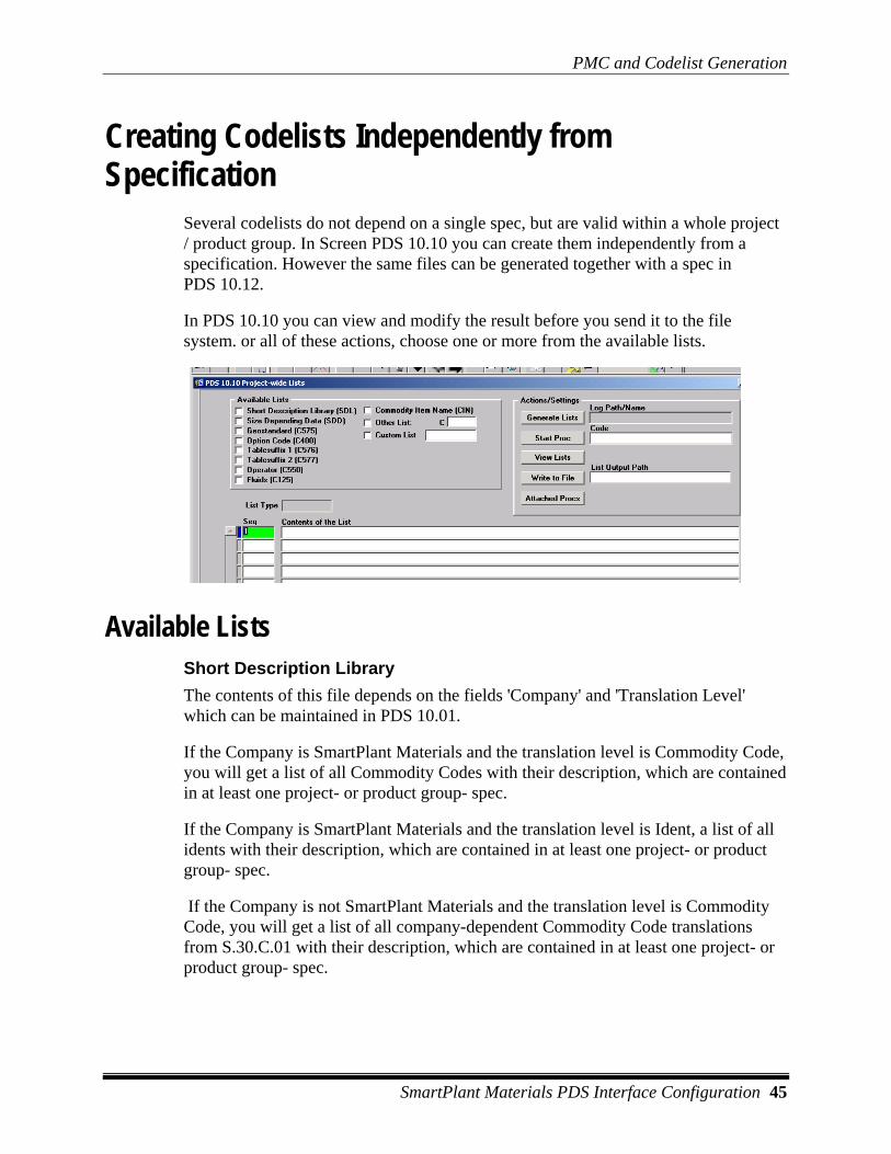
Several codelists do not depend on a single spec, but are valid within a whole project / product group. In Screen PDS 10.10 you can create them independently from a specification. However the same files can be generated together with a spec in PDS 10.12.
In PDS 10.10 you can view and modify the result before you send it to the file system. or all of these actions, choose one or more from the available lists.
Available Lists Short Description Library The contents of this file depends on the fields 'Company' and 'Translation Level' which can be maintained in PDS 10.01.
If the Company is SmartPlant Materials and the translation level is Commodity Code, you will get a list of all Commodity Codes with their description, which are contained in at least one project- or product group- spec.
If the Company is SmartPlant Materials and the translation level is Ident, a list of all idents with their description, which are contained in at least one project- or product group- spec.
If the Company is not SmartPlant Materials and the translation level is Commodity Code, you will get a list of all company-dependent Commodity Code translations from S.30.C.01 with their description, which are contained in at least one project- or product group- spec.

PMC and Codelist Generation
46 SmartPlant Materials PDS Interface Configuration
If the Company is not SmartPlant Materials and the translation level is Ident, you will get a list of all company-dependent Ident translations from S.80.C.01 with their description, which are contained in at least one project- or product group- spec.
The contents of the Commodity Code/Ident description can be manipulated to be user-specific. For example, if you do not want to see the CC-Short Desc but the long Description, it is possible by altering the CIP (m_pck_pds_custom). Also, see the help on the check box 'Short Desc Lib' in PDS 10.01 for more information.
Size Depending Data For all Idents needed in a product group/project , Size Dependent Data is created with the following attributes:
Commodity Code DNRed DNGreen SchThrot SchThGreen Ident
The SchThrot SchThGreen will be found with the fields 'Wallthick 1' and 'Wallthick 2' in PDS 10.01 if you are working in DIN. Use the radio group 'DIN or ANSI' in PDS 10.01 to determine whether to look for schedule or for wallthicknesses.
The Ident Code will be printed out, not the Ident. Only commodities are printed out, which are within a specification.
No Size Dependent Data are printed out for screws. The interface recognizes screws from the Zydex Code (6Q3C97s, 6Q3C98, 6Q3C95).
The Schedule is changed with the following logic:
• $.375 translates into .375
• S$40 translates into S-40
Size Dependent Data should only be generated if really required, since this event may last very long.
Geostandard - Lists the geostandards depending on the Method you chose in PDS 10.01 and the short description of the associated table detail.
Option Code - If the 'Generate CL400' in PDS 10.01 check box is selected, the list contains the commodity id with commodity code and short desc, where the commodity id is equal to the option. If the check box is not selected, no output will be generated.
Tablesuffix 1 - Lists the Tablesuffix 1 depending on the Tablesuffix-Method in PDS 10.01 and the name and short desc of the assigned geometric.
Tablesuffix 2 - Lists the Tablesuffix 2 depending on the Tablesuffix-Method in PDS 10.01 and the name and short desc of the assigned geometric.
Operator - Lists the Table Detail Code and its Short Description of a table mapped as CL550 for those commodity groups which have the mapping ARM. The table has

PMC and Codelist Generation
SmartPlant Materials PDS Interface Configuration 47
to be contained in the CC. You can have more than one table for this purpose. Map additional tables by appending an running number to the mapname like <mapname>_1 etc in A.50.I.01.
Fluids - Lists the fluids depending on the method chosen in PDS 10.01.
Commodity Item Name - Lists the Zydex Codes defined in the table mapped as ZYDEX, preceded and sorted by the value found on ATTR_NUM3 of the Zydex-Table.
Other List - The list name has to contain three digits (e.g. XXX). During generation, SmartPlant Materials will search for a table with the map name CLXXX and print its Table Detail Code with its Short Description.
Custom List – The list name can contain 10 characters. This list is not automatically filled by SmartPlant Materials. You may write a PWL or INDEPD procedure in PDS 10.03. Use the checkbox and field to display and/or write the generated list to file.
Actions / Settings View Lists - Press this Button to display the lists selected with checkbox.
Generate Lists - Press this Button to generate the lists selected with checkbox.
Log Path/Name - Every generation run will produce one unique logfile (independent of the number of lists you included) on the server, if the general requirements for logfiles are fulfilled. Use the screen A.60.61 to determine message level and time capture. The Logfile Path/Name will not be stored in the database. The logfile can be viewed by double-click on the item.
Write to file - Press this Button to create flat files from the lists selected with the check box.
List output path - When entering the screen, SmartPlant Materials tries to fill it with the value of the project default ZI_PDS_DIR. Refer to A.20.12 for more information on this topic. When you enter the field you will be able to choose another path via LOV. This will not update, but override the project default. The change will not be stored in the database. When closing and opening the screen PDS 10.10 , it will be reset to project default. Don't effort to determine a filename. The filename will depend on the list type you chose to write.
In the Web environment, the DBA setting PDS_DOWNLOAD_DEST will be used as list output path. After generation, the user will be prompted to download the generated file(s). Maintain PDS_DOWNLOAD_URL to find the files for download.
Start Proc – You can start INDEPD type procedures that were defined previously in PDS 10.03. Enter the code (name) of the procedure to start in the field right to the

PMC and Codelist Generation
48 SmartPlant Materials PDS Interface Configuration
button. You may use this function to create custom lists. Use the ‘Custom List’ checkbox on the left side to display and write the list to file.
Attached Procs – This button displays the second window, where you can maintain a set of procedures previously defined in PDS 10.03 and have the type PWL.
These procedures are started automatically after generation run of any list type. You can define an order of execution in the Seq field, select a procedure code (name) from PDS 10.03. Uncheck the Active checkbox to exclude one or more procedures from the set of procedures being started.
List Display Area You can view generated lists and update, insert and delete those like overall SmartPlant Materials. Before you insert new rows to a list, you have to query the previous result of this list, which must contain at least one record.
• List Type - Shows the type of the displayed list. It corresponds to the short title of the list. This short title appears in brackets after the full name of each type right to the check box in the upper area Available Lists of the screen. For the type of the other list, the value is preceded by the letter 'C'.
• Sequence - The output file will be ordered by this number, but the number itself will not be part of the file. You can change the standard sorting order manually.
• Contents of the List - This Text will be contained in the output-file. You can change it manually.

PMC and Codelist Generation
SmartPlant Materials PDS Interface Configuration 49

PCD Special Settings (PDS 10.01 / 10.02)
50 SmartPlant Materials PDS Interface Configuration
PCD Special Settings (PDS 10.01 / 10.02) Settings in PDS 10.01
Order/Sequence This value has consequences on the ASCII file concerning the keyword that is placed in front of the sequence line. Possible values are “Order” or “Sequence.” Normally “Sequence” will be used.
Sequence= 1 2 3 4 15 16
Bolt Logic If this is requested, the procedures bolt_logic and gasket_logic in m_pck_pds_custom will be started.
Those procedures can be modified, if needed. They could also be called by a PDS 10.03 procedure. (This was required before SmartPlant Materials 5.4.2 to apply bolt logic.)
Bolt_logic will do the following:
1. Find the bolt lines in PCD (Zydex=6Q3C97). 2. Set bolt's green size range to the minimum and the maximum used in the spec. 3. Replace bolt's red size range by a minus. 4. Find flanged material Zydex=6Q2C03, 6Q2C01. 5. Duplicate bolt line for every different rating and tablesuffix of the flanges. The
duplicated bolt line will get the rating and tablesuffix of the flange. If the rating is prefixed by "CL", this prefix is removed for the bolt rating.
6. Delete any duplicate entries.

PCD Special Settings (PDS 10.01 / 10.02)
SmartPlant Materials PDS Interface Configuration 51
Gasket_logic will do the following:
1. Find the bolt lines in PCD (Zydex=6Q3C97). 2. Replace bolt's red size range by a minus. 3. Find flanged material Zydex=6Q2C03, 6Q2C01. 4. Duplicate bolt line for every different rating, tablesuffix, and endprep of the
flanges. The duplicated bolt line will get the rating, tablesuffix, endprep, and minimum green size “from” and maximum green size “to” for this combination of the flange. If the rating is prefixed by "CL", this prefix is removed for the bolt rating.
5. Delete any duplicate entries.
Dissolve Assemblies If this check box is selected, assemblies are dissolved: i.e., the components of an assembly are written into the PCD.
The beginning of an assembly in the neutral file in is labeled in front of the Commodity code of the assembly by a '+'. If the codelist 400 is not generated automatically, the components of an assembly get the option code 5000+x, in which X of the option is the code of the assembly.
Filter If this check box is selected, the pipe class is analyzed in the PCD as shown in S.50.07. If you have defined a pipe in the Nominal Size range from 15 to 100 in your pipe class, without having marked the filter, the PCD would show all the Nominal Size range from 15 to 100. But if you select the filtering check box, the singular Nominal Sizes are broken down to all available sizes as can be seen in S.50.07. Our example would look as follows:
DN from DN to
15 15
20 20
25 25
32 32
40 40
50 50
65 65

PCD Special Settings (PDS 10.01 / 10.02)
52 SmartPlant Materials PDS Interface Configuration
DN from DN to
80 80
100 100
The filter check box has to be selected, if you want to work with the branch option. See Branch Opt on page 52.
Branch Opt Use Preference in Branch Table as Option in PCD?
If this check box is selected, the option is taken from the Branch Table in S.40.05. Of course, this applies only for those parts, which are qualified as branch, and which have been assigned for the particular pipe class in S. 50.03.
Gen. Elbows If this checkbox is selected, bows with the following Model Codes will be duplicated:
E45LR, E90LR, B45, B90, PB45, PB90
A further entry in the PCD is produced for this bow automatically. It has the same data, except the Model Code, which is changed to a flexible bow of same angle.
Sort by CC Should the lines in the PCD output be sorted by Commodity Code? Otherwise the order sequence is Zydex (PIPING first) per default.
Issued Only Should file output of PCD (Button ASCII in PDS 10.12) only be allowed for issued specs? This is a new function in 5.5.1.
Include Tags Set this checkbox to include non spec tagged items in the SDL. Those items have a commodity code with the item rule TWM or TFM.
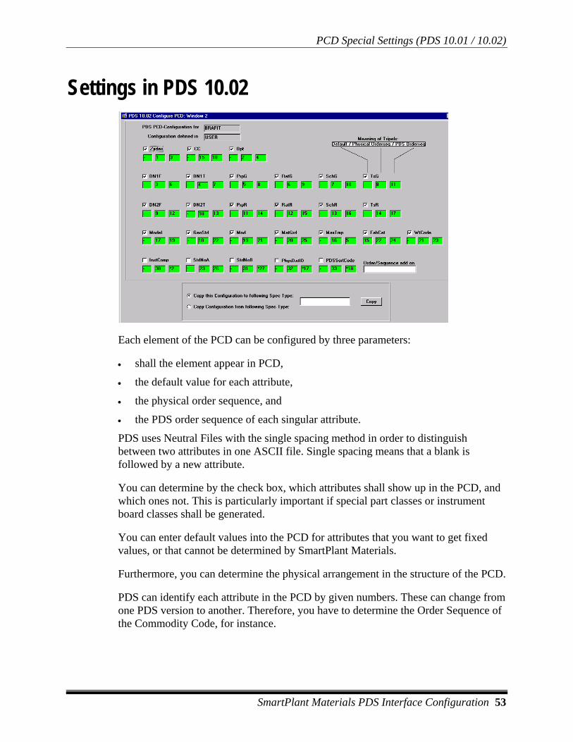
PCD Special Settings (PDS 10.01 / 10.02)
SmartPlant Materials PDS Interface Configuration 53
Settings in PDS 10.02
Each element of the PCD can be configured by three parameters:
• shall the element appear in PCD,
• the default value for each attribute,
• the physical order sequence, and
• the PDS order sequence of each singular attribute.
PDS uses Neutral Files with the single spacing method in order to distinguish between two attributes in one ASCII file. Single spacing means that a blank is followed by a new attribute.
You can determine by the check box, which attributes shall show up in the PCD, and which ones not. This is particularly important if special part classes or instrument board classes shall be generated.
You can enter default values into the PCD for attributes that you want to get fixed values, or that cannot be determined by SmartPlant Materials.
Furthermore, you can determine the physical arrangement in the structure of the PCD.
PDS can identify each attribute in the PCD by given numbers. These can change from one PDS version to another. Therefore, you have to determine the Order Sequence of the Commodity Code, for instance.

PCD Special Settings (PDS 10.01 / 10.02)
54 SmartPlant Materials PDS Interface Configuration
These definitions are carried out per Spec Type and project. You can define a Spec Type in product group and have two different Configurations: One in project A and another in project B, assuming, that both projects are based on the same product group.
Each Configuration from the project or associated product group can be copied from another spec type to the one you are in. Additionally, you are allowed to distribute your actual configuration to other spec types in the same project/product group. Use the radio button at the bottom to determine the copy direction and the field right of it to get the target or source. LOV will display all available spec types.
Copying always presupposes that the source spec type has a config, and the destination spec type has none.

Mapping Techniques in S.20.08
SmartPlant Materials PDS Interface Configuration 55
Mapping Techniques in S.20.08 Mapping in S.20.08 is a technique that is available for most of the PDS-specific attributes in the configuration (PDS 10.01). The S.20.08 screen allows the mapping between SmartPlant Materials commodity parts and PDS information (for example, Modelcode). It allows even mapping on a Commodity Code level, if required.
The first and second blocks of S.20.08 let you select the commodity part you want to map.
The third block of S.20.08 (Table Names) displays all tables that can be used for mapping of table details. The following tables can be used:
• Tables of ‘INTERFACE’ type (A.50.02)
• Tables that have any table type, and are used in the commodity code that belongs to the selected part.
• Tables that have any table type and have a table link to M_PARTS. The table link can be created in the third block of A.50.02.
The fourth block (Part Table Details) lets you enter table group’s details of the selected table. The lines in the blocks are grouped and prefixed with the numbers 1 and 2. The number 1 stands for the value on the green end; 2 stands for the red end.
It is possible to have more than one row in fourth block. This is to enable different values for different Commodity Codes within one part. To decide, which mapping will be applied on which Commodity Code, you need the fifth block (Part Table Detail Links).
In the fifth block, enter the table details that must be used in the Commodity Code, to activate the mapping in the previous block. This makes sense only if you have multiple rows in the previous block. Making entries in this block requires that you entered a table link for each used table in the third block of A.50.02.
The attributes entered in the Part Table Detail Links are in an AND-relationship. If you use the same attribute for different Part Table Details, the one is taken with the most attributes specified in Part Table Detail Links block is used.
An example: You have a group A with a part B and want to assign a modelcode to it. The modelcode should be
• M1 if the commodity code contains a pressure/rating commodity attribute with the value 1,
• M2 if the commodity code contains a pressure/rating commodity attribute with the value 2 and a design dimensions attribute with the value 4.
• M3 should be mapped to this commodity code, if the pressure/rating is 2 while the design-dimensions are something except 2.

Mapping Techniques in S.20.08
56 SmartPlant Materials PDS Interface Configuration
This configuration can be easily entered into S.20.08. M2 and M3 have both the pressure/rating attribute 2 in their Part Table Detail Link, but M2 also has the design dimensions attribute in its Part Table Detail Links. So M2 is assigned to the correct commodity code with this commodity attributes.

Generating PMC/PCD with User-Defined Procedures
SmartPlant Materials PDS Interface Configuration 57
Generating PMC/PCD with User-Defined Procedures Defining Procedures
In PDS.10.03, you can define SQL procedures that freely influence the PDS interface results after the generation by SmartPlant Materials. In PDS 10.01, you can set the 'Run Procedures' check box so that your PMC type procedures start automatically after each PCD/PMC creation from PDS 10.12. You can also start them manually using the button in PDS 10.12. Use PDS 10.04 to assign a list of procedures to each spec type.
PWL type procedures can start automatically after project-wide list generation in PDS 10.10. You can attach a list of procedures to each project in PDS 10.10.
Defining procedures requires SQL knowledge.
PDS procedures that have the PMC type can contain a single SQL like : update m_pds_pcd set
or update m_pds_pmc set
Next comes the attribute name(s) and the value(s) you want to change.
Do not put semicolons at the end of your single SQL-statement. SmartPlant Materials automatically generates a Commit after execution, so do not include a COMMIT in any procedures.
Describe each statement with a header comment using double hyphen or /* */ brackets.
It is possible to define complete PL/SQL Bodies (declare..begin..end) that contain calls to existing PL/SQLs Functions, Procedures, or Packages or to define single calls to Functions, Procedures, or Packages. For a PMC type procedure, you can use the string &PMC_ID and &SPEC_HEADER_ID that will be replaced by your actual values during runtime. If none of either string is found in a procedure, SmartPlant Materials assumes that it is a conventional (non-procedural) statement (insert, update, delete) to which is appended: where pmc_id =... resp. And pmc_id = ...
If the type of the procedure is PWL or INDEPD, SmartPlant Materials will not append anything to the procedure text, but if the type is PWL, the placeholder &LIST_TYPE will be replaced by the list type which was just generated by the standard function. The usage of this placeholder is the following:
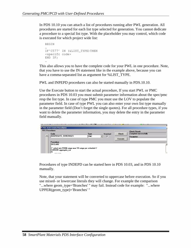
Generating PMC/PCD with User-Defined Procedures
58 SmartPlant Materials PDS Interface Configuration
In PDS 10.10 you can attach a list of procedures running after PWL generation. All procedures are started for each list type selected for generation. You cannot dedicate a procedure to a special list type. With the placeholder you may control, which code is executed for which project wide list:
BEGIN … IF’C577’ IN (&LIST_TYPE)THEN <specifc code> END IF; …
This also allows you to have the complete code for your PWL in one procedure. Note, that you have to use the IN statement like in the example above, because you can have a comma-separated list as argument for %LIST_TYPE.
PWL and INPEPD procedures can also be started manually in PDS.10.10.
Use the Execute button to start the actual procedure, If you start PWL or PMC procedures in PDS 10.03 you must submit parameter information about the spec/pmc resp the list type. In case of type PMC you must use the LOV to populate the parameter field. In case of type PWL you can also enter your own list type manually in the parameter field (Don’t forget the single quotes). For all procedure types, if you want to delete the parameter information, you may delete the entry in the parameter field manually.
Procedures of type INDEPD can be started here in PDS 10.03, and in PDS 10.10 manually.
Note, that your statement will be converted to uppercase before execution. So if you use mixed- or lowercase literals they will change. For example the comparison "...where geom_type='Branches' " may fail. Instead code for example: "...where UPPER(geom_type)='Branches' "

Generating PMC/PCD with User-Defined Procedures
SmartPlant Materials PDS Interface Configuration 59
Assigning Procedures In PDS.10.04 you assign the procedures to be executed to the singular Spec Types.
As described above, you can determine by the check box RunPrc whether these procedures automatically are initiated at generation, or manually afterwards. Only procedures of the type PMC can be attached to Spec Types
PMC/PCD Table Structure This is the structure of two SmartPlant Materials tables which contain PMC/PCD information. You may need it to create SQL code.
m_pds_pcd pmc_id NUMBER(12) NOT NULL spec_item_id NUMBER(12) NOT NULL short_code VARCHAR2(10) rkl VARCHAR2(16) NOT NULL commodity_id NUMBER(12) NOT NULL zydex VARCHAR2(7) NOT NULL unit VARCHAR2(10) opt VARCHAR2(10) NOT NULL dn1_from VARCHAR2(12) NOT NULL dn1_to VARCHAR2(12) NOT NULL endprp1 VARCHAR2(4) rating1 VARCHAR2(6) sch1 VARCHAR2(8) ts1 VARCHAR2(4) dn2_from VARCHAR2(12) NOT NULL dn2_to VARCHAR2(12) NOT NULL endprp2 VARCHAR2(4) rating2 VARCHAR2(6) sch2 VARCHAR2(8) ts2 VARCHAR2(4) model VARCHAR2(6) geostd VARCHAR2(6) modif VARCHAR2(5) matgrd VARCHAR2(4) max_temp VARCHAR2(6) fabcat VARCHAR2(4) weightcode VARCHAR2(3) endprpgrp1 VARCHAR2(4) endprpgrp2 VARCHAR2(4) instrument_no VARCHAR2(20) standard_note_a VARCHAR2(20) standard_note_b VARCHAR2(20) physical_data_id VARCHAR2(20) pds_sort_code VARCHAR2(20) ident NUMBER(12) NOT NULL group_id NUMBER(12) NOT NULL part_id NUMBER(12) NOT NULL input_1 VARCHAR2(10) NOT NULL

Generating PMC/PCD with User-Defined Procedures
60 SmartPlant Materials PDS Interface Configuration
input_2 VARCHAR2(10) NOT NULL input_3 VARCHAR2(10) input_4 VARCHAR2(10) free1 VARCHAR2(60) free2 VARCHAR2(60) free3 VARCHAR2(60) free4 VARCHAR2(60) free5 VARCHAR2(60) free6 VARCHAR2(60) free7 VARCHAR2(60) free8 VARCHAR2(60) free9 VARCHAR2(60) free10 VARCHAR2(60) proj_id VARCHAR2(10) NOT NULL usr_id VARCHAR2(10) NOT NULL lmod DATE NOT NULL int_rev NUMBER(6) NOT NULL m_pds_pmc pmc_id NUMBER(12) NOT NULL header_id NUMBER(12) NOT NULL datum DATE NOT NULL kind NUMBER NOT NULL pt VARCHAR2(15) dn VARCHAR2(15) branch VARCHAR2(15) tap VARCHAR2(15) gasket VARCHAR2(15) fluid VARCHAR2(15) wall VARCHAR2(15) revision NUMBER(2) mater_of_construction VARCHAR2(20) corrosion_allowed NUMBER(14,4) material_description NUMBER(6) thickness_equotation VARCHAR2(15) vent_drain_macro VARCHAR2(15) standard_note_a VARCHAR2(15) standard_note_b VARCHAR2(15) bend_deflection_table VARCHAR2(15) pipe_length_table VARCHAR2(15) cl148 VARCHAR2(6) free1 VARCHAR2(15) free2 VARCHAR2(15) free3 VARCHAR2(15) free4 VARCHAR2(15) free5 VARCHAR2(15) free6 VARCHAR2(15) free7 VARCHAR2(15) free8 VARCHAR2(15) free9 VARCHAR2(15) free10 VARCHAR2(15) proj_id VARCHAR2(10) NOT NULL usr_id VARCHAR2(10) NOT NULL lmod DATE NOT NULL int_rev NUMBER(6) NOT NULL sp_id NUMBER(12) NOT NULL shortage VARCHAR2(50)

Generating PDL (Geometrics) for PDS
SmartPlant Materials PDS Interface Configuration 61
Generating PDL (Geometrics) for PDS The generation of PDL (physical data library), or geometrics, for PDS is in principle similar to that of Commodity Codes.
You can define all kinds of PDS geometries that you need, e.g. an MAL Table for diameters and wallthicknesses.
For this, you have to give SmartPlant Materials the following two pieces of information:
1. The composition of the PDS size table name.
For this purpose, you may define a “String before,” “String after.” To include a special information, select the checkbox, and enter the position you would like to have this information in the PDL-Header-Name. Separating underscores are inserted automatically between all selected attributes. At job start time, SmartPlant Materials will step through the available commodity codes and create all possible combinations of PDL-Header-names with the mapped values of all attributes you selected here. Only items are regarded, which are in a spec. With the use of Schedules in the PDL generation the simple case is having the schedule in the commodity code. Schedule method is “S.30.01(S20.08)”. But schedules can be regarded, also if they are not in the CC. Prerequisite is, that the Schedule-method (PDS 10.01) is "Geoms." The output geometrics are filtered for the schedule. The schedule has to follow the rules of building geometrics for use of the standard version of mv_spec_item_idents. This means, that the following combinations of nominal sizes and schedules can appear: Input1: DN1 Input2: SCH1 Input1: DN1 Input2: DN2 Input3: SCH1 Input1: DN1 Input2: DN2 Input3: SCH1 Input4: SCH2 These are illegal combinations: Input1: DN1 Input2: SCH1 Input3: DN2 Input4: SCH2

Generating PDL (Geometrics) for PDS
62 SmartPlant Materials PDS Interface Configuration
or Input1: DN1 Input2: something else Input3:SCH1
2. The attributes in the size table.
Enter the attributes you need in the PDL table. While SmartPlant Materials is executing a PDL-generation run, it steps through the available commodity codes and collects the attached geometrics (S.40.22). It will regard every geometric that has at least one of the attributes mentioned in PDS 20.01. The link to combine/connect all participating geometrics in one size table are those attributes checked as “Input” in PDS 20.01. The text for the attribute can be changed in PDS 20.01, which has no influence on the data in A.50.01.
Enter all information into PDS.20.01. In PDS 20.10, SmartPlant Materials will process all selected PDL rules one after the other.
Conversion of Geometries If another unit of measurement for the geometry attributes is selected in PDS.20.01, the conversion will be accomplished in accordance with A.10.13. The unit assigned in A.50.01 is entered automatically when entering an attribute here. If the unit is not changed, no conversion is carried out.
The text for the attribute can be changed, without changing the data in screen A.50.01.
For example, a MAL Table shall not be generated for every kind of connection. MAL Tables are connect geometries. Connect groups must be assigned to all connect geometries, so that the interface generates MAL Tables only for the connect groups

Generating PDL (Geometrics) for PDS
SmartPlant Materials PDS Interface Configuration 63
where it makes sense. For example, no MAL Table is generated for connect group 200.
This assignment is accomplished in PDS.20.03.
A similar situation applies to the Commodity Geometric. Not all Commodity Geometrics shall be generated for each Zydex Code.
This assignment is done in PDS.20.02
After having made the required definition, you change to module PDS.20.10. There you can generate the geometries defined before.
The mask then displays all the kinds of sizes defined before.
In principle, the generation of geometries always proceeds in two phases:
1. Generation of the geometrics in SmartPlant Materials Tables. 2. Generation of the corresponding ASCII files.
By this, you can check the PDS geometric on completeness and correctness comfortably in SmartPlant Materials before.
In PDS 20.10 you can perform the following actions:
• Select all. All of the defined PDL rules are marked to be generated.
• Clear Selection. All check boxes are cleared, whether they were checked by Select all or manually.

Generating PDL (Geometrics) for PDS
64 SmartPlant Materials PDS Interface Configuration
• Chk UPD. The resulting size tables are selected whether the original SmartPlant Materials geometries have been changed. Changed PDS size tables get the status Update.
• Gen UPD. After the Chk UPD run, this button regenerates all PDL rules with the status Update.
• Gen selected. All PDL rules with their check box selected are (re)generated in SmartPlant Materials.
• Batch (Gen sel). All PDL rules with their check box selected are (re)generated in SmartPlant Materials within a JCS batch job.
• All ASCII. All available geometries are generated as ASCII files.
• New ASCII. Only the geometries with the status NEW are generated as ASCII files.
• A geometry gets the status NEW, if it was generated for the first time, or if the original SmartPlant Materials geometry was changed and an update run was started.
The fields on the first page of and their meaning:
• New. Quantity of generated PDL names with the status NEW.
• OK. Quantity of PDL names which were generated as ASCII file.
• Update. Quantity of generated PDL names which need an Update.
• Invalid. Number of the PDL names with data missing.
• #PDL-Name. Quantity of generated PDL names (always the sum of all items above)
• Records. Quantity of geometry records for all PDL names
• Next Block. Takes you to the next block where the singular PDL names are displayed:
Names for PDS geometries beginning with "!” (like in !NDF) imply the same as in PCD (in the present example: No Data Found).
The status of the PDS geometries are shown in the field ‘Status‘.
The quantity of records generated for this geometry is shown under ‘#Records‘.
Field ‘Units‘ : Different unit text for the PDS geometrics: For the PDS geometries, the value translated from A.10.14. is shown in the line Units=.....

Generating PDL (Geometrics) for PDS
SmartPlant Materials PDS Interface Configuration 65
By clicking the View CC Button, you can view the Commodity Codes that were the base for the PDL name generation.
If you choose Geoms here, you see the geometrics that will be the base for the PDL geometrics data generation.
Pressing the Back button twice, brings you back to the second page of PDS 20.10.
By clicking the Gen Geometric button, you can restart the SQL statement generated before.
Error Reason shows the reason the PDL name has the status Invalid Generation.
Error Reasons for Invalid Generation: • PCD Data in Commodity Code is incorrect. An incomplete PDS
geometry name was generated.
• Invalid Number of Attributes. The SQL statement has less attributes, than required by the definition for the PDS geometry. By scrolling to the right, you can view the SQL statement and find out which attribute is missing.
• You have either selected a wrong attribute during attribute structure definition, or the geometries appended to the Commodity Code do not contain all attributes needed for this geometry.
• No Records where inserted by SQL Statement. The SQL statement is okay., no records were generated, however.
• Generated Geometric Data contains 0 or NULL values. The generated PDS geometries contain zeros.
• None unique INPUT fields. The fields defined as Input are not unique, e.g. double Nominal Sizes.

Generating PDL (Geometrics) for PDS
66 SmartPlant Materials PDS Interface Configuration
Tuning Generated SQL Statements The first time, the SQL statement SQL-Text is created by the program. Later it is possible to modify it. Double-clicking on this field leads to the PDS PDL procedures, where you can store the SQL statements.
By clicking the button View PPP, you jump to the block where you can maintain PDS PDL Procedures. When using this button, SmartPlant Materials will try to find an existing PDL procedure with the actual PDL-header name.
The PDL-Procedure Name is unique within one project. If you try to insert a second identical one, you will get an error message. You can choose the name of an existing PDL-Header for your Procedure via LOV or create your own name. The PDL-Procedure does not keep the information from which PDL-Rule (PDS.20.01) or from which PDL Header Result it was derived (except the PDL Header Name if you want it). In EnterQuery-Mode you can use the LOV to retrieve a list of all existing PDL-Procedure-Names.
To save the PDL-Procedure to a certain result, check the check box 'Save to Result' at the bottom of the block. You can leave the fields 'PDL Rule Code' and the 'PDL Header Name' empty, to copy the procedure back to the actual Header Result. Alternatively, choose a destination using LOV. Additional Hint: You can distribute one procedure to several Header Results by just re-checking the 'Save to Result' check box after a successful commit.

Generating PDL (Geometrics) for PDS
SmartPlant Materials PDS Interface Configuration 67
Geometric Generation Important Information Rule for PDS Geometry Generation: SmartPlant Materials geometries 'appended' to the corresponding Commodity Codes are considered to be the base of the PDS geometry generation (see S.40.22).
If a Table Suffix is used for the generation of the PDL name, those geometries are neglected which do not correspond to the Table Suffix.
Tables with a name prefix MAL_ only use geometries with Table Suffix.
From the rest of geometries only those are used which have at least one attribute relevant for the PDS geometry.
All remaining tables are joined, and the result is printed out.
Schedules • The leading S (S-) of Schedule is eliminated. (If the PDL Header
Replacement Chars in PDS 10.01 contains the minus (-), S- will be replaced by S$ and for that NOT eliminated.)
• Schedules only can be set if idents exist.
Conversion of Geometrics If another unit of measurement is selected in PDS.20.01 for the geometry attributes, these are converted in accordance with A.10.13. The unit assigned in A.50.01 is entered automatically when typing in an attribute here. If the unit is not changed, no conversion is carried out.
The text for the attribute can be changed, without any influence on the data in A.50.01.
The conversion is carried out via the following formula:
(Value * Add1) *Factor+Add2
Different unit text for the PDS geometries: For the PDS geometries, the value translated from A.10.14. is shown in the line Units=.....

Generating PDL (Geometrics) for PDS
68 SmartPlant Materials PDS Interface Configuration
Configuring PDL Specials (PDS 10.01)
0 Allowed If selected, sizes which equal to 0 are not regarded as invalid.
Calculate Weight If selected, weight will be calculated. Weights are entered independently from the material, for a gamma to be defined by you.
You enter this gamma into A.20.02.01 or A. 20.02.02. In addition, you enter into this mask your geometrical attribute, containing the weight.
During the generation of PDS geometries, the attribute representing the weight is derived from the following formula:
Specific weight from CL578 = a
Weight from geometry = b
Gamma = g
a * b
-------
g
PDL Header Replacement Chars Characters, contained in this field will be replaced by a '$' symbol during generation of PDL header names. (Note, that if schedule is prefixed by 'S-' and is replaced by 'S$', 'S-' cannot be eliminated by the standard logic.)
Accessing Files on the Web
SmartPlant Materials PDS Interface Configuration 69
Accessing Files on the Web When you write the output of the PDS interface to the file system in a client/server environment, the files are placed on your local client. Using the web, they are written to the application server. So, in the web environment there is an additional step: You are prompted if you want to download the generated files. To enable the download (in PDS 10.10, PDS 10.12, PDS 10.14, PDS 20.10) you have to maintain the DBA setting in A.60.04 for PDS_DOWNLOAD_DEST to determine the destination of the text file on the application server. The value can look like this:
d:\marian541\pds_files
The path can be chosen deliberately, but it must exist on the application server. Do not append a trailing backslash here.
After the file is created, you are prompted if you want to download the file. If you confirm, you get a new browser window which supplies the file. Maintain the DBA setting in A.60.04 for PDS_DOWNLOAD_URL
The value can look like this: your_web_server/pds
The name of your web server is followed by a virtual directory name. Do not append a trailing slash. You have to define an alias in the web server configuration. In the 6iserver.conf file on the application server, there should be a line that looks like the following:
alias /pds/ "d:\marian541\pds_files/"
The right hand entry must match the PDS_DOWNLOAD_DEST except that a slash is appended. The left hand entry must match the PDS_DOWNLOAD_URL, but the server name is omitted, and a trailing slash is added.

BOM Import Configuration (PDS 30.01)
70 SmartPlant Materials PDS Interface Configuration
BOM Import Configuration (PDS 30.01) The material used in PDS can be transferred to SmartPlant Materials via OMI (B.40). You can use the PDS MTO-report 'piping_g.rpt' or other formatted reports to spool out your items to the file system. We will explain two examples: The first kind of format, we will call “piping_g,” and the other we will call “ISOGEN”. Both these names only stand for two different ways to format your PDS output, and they are not fixed.
However, on the PDS 30.01 screen, you configure where OMI can find the data. You have to define at least one configuration and reference to it in B.40.01 to enable OMI to read from PDS report. In PDS 30.01 you can define sets of configuration items. At least one configuration must be entered to enable OMI reading from PDS report. Each configuration can be used system-wide, which means if you have the same layout for the PDS report for all product groups and projects, you probably will have only one record in this screen for overall SmartPlant Materials.
For each config set you configure the items that are important for OMI to read them. For piping_g, you do not have to configure all items. Only LINE_TYPE is mandatory. If you specify one of POS_CC, POS_QTY, POS_SIZE1, or POS_SIZE2, you have to specify all of these four. In general, it is a good working practice to specify all attributes needed to make the setting visible to the user.

BOM Import Configuration (PDS 30.01)
SmartPlant Materials PDS Interface Configuration 71
Configuration Items The ‘Item’ field holds the name of the configuration item that you want to supply with parameters. The available items can be fetched via LOV. The LOV automatically fills some of the other fields with defaults, so you can easily achieve a default configuration.
The config items in detail are as follows:
• LINE_NUM. You can define the horizontal location of the line number. In the field 'Value' you can enter your line number title which can differ from the literal 'LINE NUMBER' (which is the default). This information is used to identify a physical line in the report as line number information. If you don't use this configuration item, the standard PDS defaults take place. This config item is not used with “ISOGEN”-like formats.
• LINE_TYPE . The line type defines which node type the line will have in SmartPlant Materials BOM. Choose from the available node types with LOV on field 'Value'. The node type code is stored, and no internal id. So the node type for every project can be the same. This config item is required to be defined by you. There is no default by the system. This config item is not used with “ISOGEN”-like formats.
• LINE_ATTR. You can have the interface interpret your line number and make node attributes of it. Specify the name of the attribute in the field 'Value' (LOV on Attributes is provided) and enter the location in the digit-fields. You can have more than one usage of LINE_ATTR by selecting this Item for more than one row in the block. If you do not use this config item, the line number is stored in the short desc, description of the node, and no node_attributes are generated. The attr code is stored, and no internal id. So the attr code for every project can be the same. This config item is not used with “ISOGEN”-like formats.
• LINE_SEP. If you choose to define relative locations, you can herewith define the separator symbol within the line number in the field ‘Value’. If you omit this config item, the dash is taken per default. Refer to description of the field 'Type' for further information on defining relative or fixed locations. This config item is not used with “ISOGEN”-like formats.
• POS_LEVxN. The name of the node level x where the material is to be stored. You can create up to 10 levels (beginning from 0 to 9) from the start node defined in B.40.01. If the node does not exist in the BOM, it will be created. This config item is normally not used with “piping_g”-like formats.

BOM Import Configuration (PDS 30.01)
72 SmartPlant Materials PDS Interface Configuration
• POS_LEVxT. The type of the node level x where the material is to be stored. You can create up to 10 levels (beginning from 0 to 9) from the start node defined in B.40.01. The node type is needed when new nodes have to be created within the BOM tree. This config item is normally not used with “piping_g”-like formats.
• POS_CC. Enter the location of the Commodity Code in the digit-fields. Trailing and leading blanks are cut off automatically. If you omit this config item, the defaults from PDS piping take place. Idents can be found with CC and sizes. However, if the spec code (POS_SPEC) is supplied together with the CC and no short code is supplied, PDS BOM import will try to find a short code for this CC.
• POS_IDENT. Enter the location of the Ident Code in the digit-fields. Trailing and leading blanks are cut off automatically.
• POS_OPTION. Enter the location of the option in the digit-fields. Trailing and leading blanks are cut off automatically. If you omit the option, it defaults to 1.
• POS_SHORT. Enter the location of the Short Code in the digit-fields. Trailing and leading blanks are cut off automatically. If you do not have a Short Code in your file, the program will search for one with the Spec Code, Option Code, and Commodity Code. If there is nothing found, the program will receive an error. It is a good idea to define a Short Code “ERROR” in S.10.08. The program will then assign this Short Code to the item, where no Short Code was found, and the import will succeed. You will be informed which line was not imported because ERROR was not in the spec.
• POS_SPEC. Enter the location of the Specification Code in the digit-fields. Trailing and leading blanks are cut off automatically.
• POS_RTYPE. Enter the location of the Record Type in the digit-fields. Trailing and leading blanks are cut off automatically. The Record Type influences the interpretation of the POS_QTY. This config item is normally not used with “piping_g”-like formats. If the RTYPE is PIPE or BOLT, missing quantities don’t default to 1. If you do not specify an RTYPE, it defaults to BOLT. If the RTYPE is PIPE, the program appends a “.0” to integer quantities if no unit is specified. This “.0” makes the program assume a length unit for the quantity because of the decimal point. If the RTYPE is BOLT and the program fetches commodity code with sizes from SmartPlant Materials, the bolt also receives a second size (the bolt length) if the input2 is numeric – regardless whether the bolt is marked as one-size or two-size item. Additionally if there is an input2 (bolt-length) in the ASCII file, the program will compare the input2 from ident with the input2 from ASCII. If they are different, the program will try to find another ident within the same Commodity Code which matches the bolt diameter and length. If an ident was found, it will be taken instead

BOM Import Configuration (PDS 30.01)
SmartPlant Materials PDS Interface Configuration 73
of the one originally coming with the ASCII. If no ident is found, an error message is written to the job logfile, and the ident is erased. Instead, the BOM position will contain the commodity code, input 1 (bolt diameter) and the new bolt length. If the RTYPE is COMP, the program converts the quantity to number, if no unit is specified. This conversion cuts trailing zeros and makes the program assume a piece unit for the quantity because of the decimal point. To make the RTYPE being noticed, the RTYPE has to be defined left from the quantity or size2 in the ASCII file.
• POS_QTY. Enter the location of the position quantity in the digit-fields. Trailing and leading blanks are cut off automatically. If the Record Type (as far as existing) is BOLT or PIPE, the quantity is set to zero if none found on the line. If the Record Type is different, the missing quantity is defaulted to 1. If there is no Record Type, the missing quantities are left out. If you omit this config item (POS_QTY), the defaults from PDS piping_g take place.
• POS_UNIT or POS_LUNIT. The OMI Preprocessor does not know if a quantity is a piece unit (POS_UNIT) or if it is a length unit (POS_LUNIT). If the RTYPE is PIPE or BOLT, missing quantities don’t default to 1. If you do not specify an RTYPE, it defaults to BOLT. If the RTYPE is PIPE, the program appends a “.0” to integer quantities, if no unit is specified. This “.0” makes the program assume a length-unit for the quantity because of the decimal point. If the RTYPE is COMP, the program converts the quantity to a number, if no unit is specified. This conversion cuts trailing zeros and makes the program assume a piece-unit for the quantity because of the decimal point. To make the RTYPE being noticed, the RTYPE has to be defined left from the quantity in the ASCII file. 1) If the quantity is blank:
• If the RTYPE is blank (for example, it is set to PIPE or BOLT), the quantity is set to 1 and the unit defaults to 'EA'.
• MM is used if POS_LUNIT is blank.
• EA is used if POS_UNIT is blank.
2) If the quantity is not blank:
• Any unit is used if it is appended to the quantity in the ASCII file. You may also use ‘" ‘to get the unit IN. Note, that the unit is case sensitive.
• POS_LUNIT is used if the quantity contains a decimal point as a separator (delimiter).
• POS_UNIT is used is the quantity does not contain a decimal point as a separator (delimiter).

BOM Import Configuration (PDS 30.01)
74 SmartPlant Materials PDS Interface Configuration
• POS_SIZE1. Enter the location of the 1st size in the digit-fields. Trailing and leading blanks are truncated. If you omit this config item, the defaults from PDS piping_g take place.
• POS_SIZE2. Enter the location of the 2nd size in the digit-fields. Trailing and leading blanks are cut off automatically. If you omit this config item, the defaults from PDS piping_g take place. This field is used for diameters, not for schedules. If you transfer schedules for some reason, and you supply a commodity code (POS_CC), the PDS BOM import will erase the schedule depending on the Zydex table in SmartPlant Materials. (If an asterisk is on attr_char1 for the associated Zydex, the item is considered to have one nominal size, and size2 is set to zero.) If the RTYPE is BOLT, and the program fetches commodity code with sizes from SmartPlant Materials, the bolt also receives a second size (the bolt length) if the input2 is numeric – regardless whether the bolt is marked as one-size or two-size item. To make the RTYPE being noticed, the RTYPE has to be defined left from the size2 in the ASCII file. Additionally if there is an input2 (bolt-length) in the ASCII file, the program will compare the input2 from ident with the input2 from ASCII. If they are different, the program will try to find another ident within the same Commodity Code which matches the bolt diameter and length. If an ident was found, it will be taken instead of the one originally coming with the ASCII. If no ident is found, an error message is written to the job logfile, and the ident is erased. Instead, the BOM position will contain the commodity code, input 1 (bolt diameter) and the new bolt length.
• POS_SIZE3. Enter the location of the 3rd size in the digit-fields. Trailing and leading blanks are cut off automatically. You only need this item to find idents for material that has more than one end and is to be found by Commodity Code and sizes.
• POS_SIZE4. Enter the location of the 4th size in the digit-fields. Trailing and leading blanks are cut off automatically. You only need this item to find idents for material that has more than one end and is to be found by Commodity Code and sizes.
• POS_SEP. If you choose to define relative locations, you can herewith define the separator symbol within position line in the field ‘Value’. If you omit this config item, the blank is taken per default. Refer to description of the field 'Type' for further information on defining relative or fixed locations.

BOM Import Configuration (PDS 30.01)
SmartPlant Materials PDS Interface Configuration 75
• POS_ATTR. You can transfer an unlimited number of position attributes for each position of the SmartPlant Materials BOM structure. Enter the location of the position attribute in the digit-fields, and the name of the attribute in the value-field.
• POS_SUM_ID. If you want to summarize material that has the same ident within the same node/list status/issue status, set this item to the value Yes, Y, True, 1, or ON. If you do not want to sum up, you can omit this config item. Summarizing will only take place for material that is characterized by the same parameters. For example, if one position has only the ident code while the other has no ident but spec, short code, and size information, these cannot be added, even if they refer to the same ident. They will remain as two separate positions. Summarizing will only supply the correct values, if they are of the same unit. The unit of identical idents will not be converted to each other by the program. If you add 1 meter pipe to 3000 mm pipe, the result will be unpredictable.
• POS_TAG_NU. Enter the location of the tag number in the digit-fields. If a tag number occurs without ident on one ASCII line, it is treated as item rule TWM. (One item type in A.10.15 with rule TWM has to be checked as default.) Users can submit CCL short/long to create CC. If a tag number occurs together with an ident, the item rule will be considered to be SWT. (One item type in A.10.15 with rule SWT has to be checked as default.)
• POS _TAG_SH. Enter the location of the tag number short layout in the digit-fields. This setting is only of interest, if you are working with POS_TAG_NU and create tags with item rule TWM. (One item type in A.10.15 with rule TWM has to be checked as default.)
• POS _TAG_LO. Enter the location of the tag number long layout in the digit-fields. This setting is only of interest, if you are working with POS_TAG_NU and create tags with item rule TWM. (One item type in A.10.15 with rule TWM has to be checked as default.)
• POS_CC_MAP. You can receive commodity codes in an interface- or company-specific translation. You have three characters to indicate what translation should be used: "M" for original SmartPlant Materials, "I" for interface specific, "C" for company-specific commodity codes. The order of these characters specifies the search order. The value "CIM" would mean: first look for a commodity mapping, if none found, look for an interface mapping. If none found, assume the normal commodity code from S.30.01. In this example, you could have omitted "M", because the normal commodity code is looked up per default, if nothing else was found. You do not have to use all of the three characters: "C" is also a valid example value for POS_CC_MAP. The interface code for interface mappings is "PDS". The company code for company mappings is taken from PDS 10.01 PDS configuration screen, or if no config was done, from Company entry in B.40.01. POS_CC_MAP will replace Company-or InterfaceCommodity Codes by SmartPlant Materials Commodity Codes to

BOM Import Configuration (PDS 30.01)
76 SmartPlant Materials PDS Interface Configuration
be processed by standard OMI. Note, that POS_CC_MAP will not work, if you chose to activate the checkbox “Map Commodity Codes/Idents” in B.40.01. Activating this checkbox will cause the PDS OMI transfer to stop processing. For Company Ident Codes, you also need to set POS_CC_MAP to indicate that you want to map, although the value of POS_CC_MAP is not relevant. Company Ident Codes are always looked up first. If not found in project/product group, a SmartPlant Materials Ident Code is assumed. Interface Ident Codes are not supported. If you plan to use only SmartPlant Materials codes in your OMI load, do not include the POS_CC_MAP config item in your config, to save time which is spent looking up company- and interface-mapping tables.
• POS_NATTR. You may specify an arbitrary number of node attributes for each node of the SmartPlant Materials BOM structure. Enter the location of the position attribute in the digit-fields, and the name of the attribute in the value-field. To transfer the attributes correctly, the first position row which is on another (or on the very first) node has to contain the node attributes with their values. The node attribute information on all following position rows for the same node in the import file will be simply ignored.
• POS_IATTR. You may specify an arbitrary number of ident attributes for each position of the SmartPlant Materials BOM structure. Enter the location of the ident attribute in the digit-fields, and the name of the attribute in the value-field. Using ident attributes will cause the preprocessor relate the material to the item rule TAB, unless you specify otherwise with POS_ITR.
• POS_ITR. You may specify the item rule explicitly in the ASCII file. Enter the location of the item rule in the digit-fields. If you don’t specify the item rule, following rule applies: If a tag number occurs without an ident on an ASCII line, it is treated as item rule TWM. If a tag number occurs together with an ident, the item rule will be considered to be SWT. If there is no tag number specified, the item rule will be SOT. One item type in A.10.15 of each item rule you want to apply has to be checked as default.
• POS_CG. The commodity group can be submitted in the ASCII file. Enter the location of the commodity group in the digit-fields.

BOM Import Configuration (PDS 30.01)
SmartPlant Materials PDS Interface Configuration 77
• POS_CP. The commodity part can be submitted in the ASCII file. Enter the location of the commodity part in the digit-fields.
• POS_MODEL Model Code from PDS. This value will not be inserted by the standard- procedure into the BOM. You can use it for example for any customized code in m_pck_pds_bom_custom. See the example function CREATE_OR_SUM_SPECIAL_ITEMS. When the return value from this function is ‘1’, the standard-insert in m_import_interfaces will be replaced by the insert in the CIP.
• POS_CIP1 – 3. This values will not be inserted by the standard-procedure into the BOM. You can use it for example for any customized code in m_pck_pds_bom_custom. See the example function CREATE_OR_SUM_SPECIAL_ITEMS. When the return value from this function is ‘1’, the standard-insert in m_import_interfaces will be replaced by the insert in the CIP.
• POS_NUM. The position number can be submitted in the ASCII file. Enter the location of the position number in the digit-fields. To transfer position numbers, you have to set the project default ZI_OMI_POS to DATA.

BOM Import Configuration (PDS 30.01)
78 SmartPlant Materials PDS Interface Configuration
Configuring BOM Report Item ‘Type’ (PDS 30.01)
On the Configure BOM Report Screen (PDS 30.01), type can have three possible values:
• Column (C) means that you want to define the horizontal position of the item in fixed column numbers. 'Digit from' contains the first column to be read from the PDS file and 'Digit to' contains the last column to be read. These both fields have to be filled if you use this type for an item. Otherwise, the program will cause a data jam. The fixed column numbers are read before the sequential order information. That means, when you begin to specify an item sequential (type 'Sequence'), you cannot return to fixed column numbers. If you use ‘Column’, you may use the same position in ASCII to feed multiple config items.
• Sequence (S) means that you want to define the horizontal position of the item in sequence with lowest first and highest last. The field 'Seq' contains the sort order, which defines when the specified item is expected in the PDS file. The step size of the sequence value can be different from 1, and the first sequence can be different from 1. You can even use negative values. The field 'Length' contains the last column to be read. The length is counted from the beginning of the new item. Leading blanks will not be regarded. While 'Seq' is mandatory, the 'Length' can be omitted. If you omit the length, the program reads the item until it comes to the specified line/position separator symbol.
• Other (O). The config item has neither fixed-column nor sequential information.

BOM Import Configuration (PDS 30.01)
SmartPlant Materials PDS Interface Configuration 79
Creating ASCII-File from PDS-3D (piping_g) Choose the Report Manager from the main menu:
Maintain:
• Report Discrimination Data
• Report Search Criteria
This determines the material to be printed on the report.

BOM Import Configuration (PDS 30.01)
80 SmartPlant Materials PDS Interface Configuration
Then choose the Report Format.
Click Create for a new report:

BOM Import Configuration (PDS 30.01)
SmartPlant Materials PDS Interface Configuration 81
Enter a new report format like shown below. Be sure to use the format piping_g. (When you read the chapter and understand how the program interprets the file, you can as well define your own report format which is free of overhead information. This could have a positive effect on performance.)
In the Report Manager, select Report and decide to Revise.

BOM Import Configuration (PDS 30.01)
82 SmartPlant Materials PDS Interface Configuration
Enter the data specific to your environment. Note that OMI expects the file extension ‘.rpt‘ The name of the report file can deliberately changed.
Start the report.
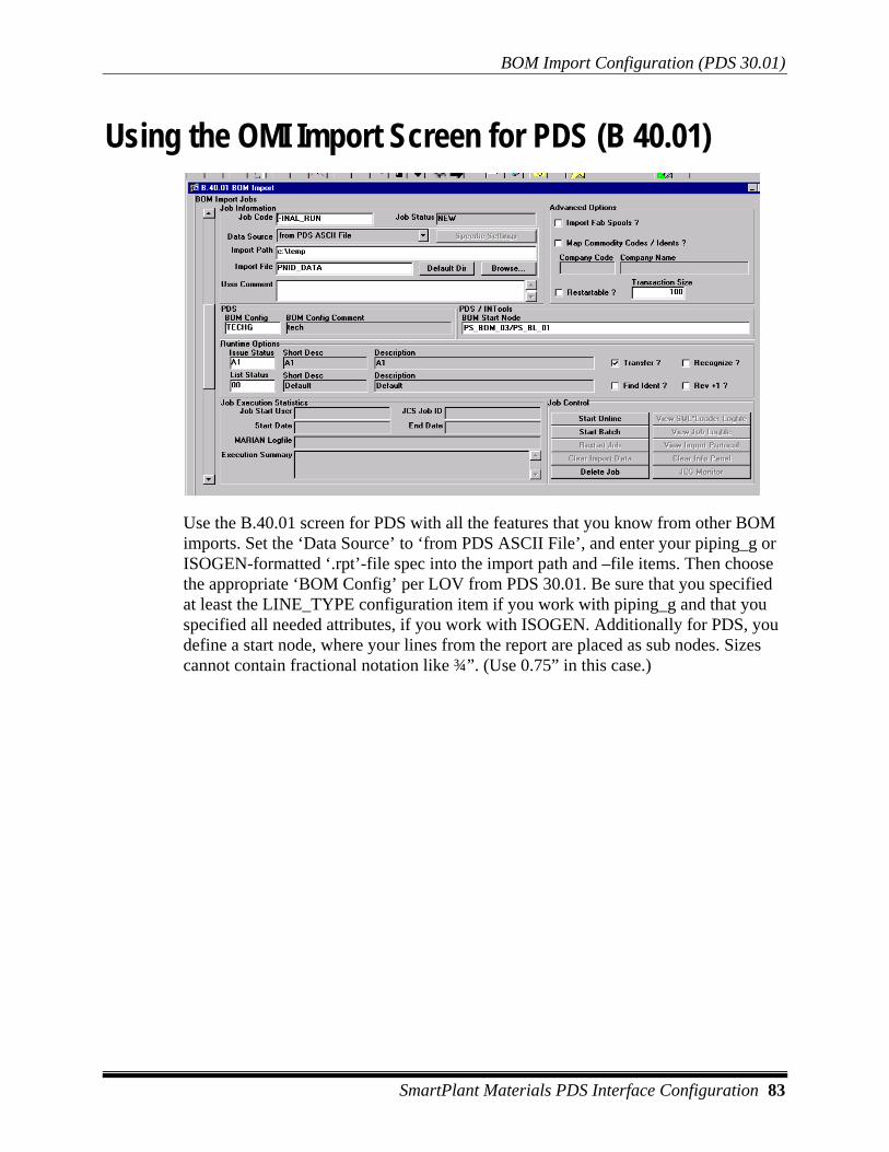
BOM Import Configuration (PDS 30.01)
SmartPlant Materials PDS Interface Configuration 83
Using the OMI Import Screen for PDS (B 40.01)
Use the B.40.01 screen for PDS with all the features that you know from other BOM imports. Set the ‘Data Source’ to ‘from PDS ASCII File’, and enter your piping_g or ISOGEN-formatted ‘.rpt’-file spec into the import path and –file items. Then choose the appropriate ‘BOM Config’ per LOV from PDS 30.01. Be sure that you specified at least the LINE_TYPE configuration item if you work with piping_g and that you specified all needed attributes, if you work with ISOGEN. Additionally for PDS, you define a start node, where your lines from the report are placed as sub nodes. Sizes cannot contain fractional notation like ¾”. (Use 0.75” in this case.)

BOM Import Configuration (PDS 30.01)
84 SmartPlant Materials PDS Interface Configuration
Interpreting the “Piping_g” File Here is a brief example of how the interface steps through a piping_g-formatted file:
1.Date/Time : 10-Jan-00 PDS MTO REPORT Page: 1 2. 3.Corporate Headquarters Sample Report 4.Intergraph Corporation 641s 5.Huntsville, Alabama 35894-0001 Intergraph 6.(205)730-2000 pds 7. 8.Commodity Code Qty/Length 1st Size 2nd Size Material Description 9.______________ __________ ________ _______ _______________ 10. 11. LINE NUMBER: A380311-3"-2C0032-HF 12. _________________________________ 13. 14.FAABBAWAAA 2 3 3 Flange, CL300, RFFE 15 16.VABBAHCAAA 1 3 3 Gate valve, CL300, 17. 33 18.PAAAAAWAAA 334MM 3 Pipe, S-STD, BE, AS 19. 20.XDABBZZQSG 2 3 - Gasket, CL300, 21. CS center ring01 22.YZZZHZZFFF 16 0.75 4.25 B31, ASTM-A1 23. 24. 25. LINE NUMBER: A380311-3"-2C0032-N 26. ________________________________ 27. 28.FAABBAWAAA 2 3 3 Flange, CL300, RFFE/BE, ... ... ... ...
1. Lines from 1-10 in our example would be recognized as BOM positions in the first cut but then eliminated because they have no valid 1st size definition.
2. The 11th line would be recognized as containing line number information (‘LINE NUMBER’). For that, the program would make up a new node within the start node. The new node name is a sequence which is counted starting from 1 for each import job. The string following the ‘LINE NUMBER’ in piping_g would be written into the short desc and description of the node ( the language would be taken from the SmartPlant Materials login environment).
3. If you configured the interface to scan the line number, it would create node attributes for the line.
4. Lines 14, 16, 18, 20, and 22 would be recognized as valid positions on the new node created in step 2. If you configured OMI to find the idents, you would have chances to find them with commodity code, size1, and size2.

BOM Import Configuration (PDS 30.01)
SmartPlant Materials PDS Interface Configuration 85
5. Line 25 would be recognized as line number information. The line number would be compared to the previous one, to see if it is a new line number or just a repetition due to page break. The line A380311-3"-2C0032-N indeed is a new one, so the program would continue with step 2. Otherwise the program would have added the positions to the previous node.
Intergraph lets the users configure the layout of piping_g. With PDS 30.01 you are able to adapt the OMI interface to many of the opportunities. It may be possible (depending on your config) that the destination BOM contains lines from piping_g, which are no positions. These lines are recognized as garbage at the point when you are trying to find idents for them.
Interpreting the ISOGEN File This example shows how the interface steps through an ISOGEN-formatted file. The significant columns are listed in the following example:
GASK 3500 B S11F44F6W604D30 1 P3 3.0" BOLT 3500 B R05I3T2030 1 P3 .625 90.0 4 COMP 3500 B I01F14A7C400000 1 P3 3.0" 3.0" NREQD SCH10S 0.000 0.000 90.00 PIPE 3500 B A02P1AOC0340 1 P3 3.0" 3.0" SCH10S SCH10S 0.000 500.002 COMP 3500 B C17P5A8C3030 1 P3 3.0" 3.0" SCH10S SCH10S 114.2 0.000 90.00 PIPE 3500 B A02P1AOC0340 1 P3 3.0" 3.0" SCH10S SCH10S 0.000 400.0 COMP 3500 B C17P5A8C3030 1 P3 3.0" 3.0" SCH10S SCH10S 114.2 0.000 90.00 PIPE 3500 B A02P1AOC0340 1 P3 3.0" 3.0" SCH10S SCH10S 0.000 3975.7 COMP 3500 B D12P5A8C3030 1 P3 4.0" 3.0" SCH10S SCH10S 0.000 0.000 90.00 COMP 3500 B C17P5A8C3030 1 P3 4.0" 4.0" SCH10S SCH10S 152.3 0.000 90.00 PIPE 3500 B A02P1AOC0340 1 P3 4.0" 4.0" SCH10S SCH10S 0.000 1965.62 COMP 3500 B D10P5A8C3030 1 P3 4.0" 4.0" SCH10S SCH10S 0.000 0.000 90.00 PIPE 3500 B A02P1AOC0340 1 P3 4.0" 4.0" SCH10S SCH10S 0.000 216.43 COMP 3500 B C17P5A8C3030 1 P3 4.0" 4.0" SCH10S SCH10S 152.3 0.000 90.00 PIPE 3500 B A02P1AOC0340 1 P3 4.0" 4.0" SCH10S SCH10S 0.000 100.03 COMP 3500 B I01F14A7C400000 1 P3 4.0" 4.0" NREQD SCH10S 0.000 0.000 90.00 GASK 3500 B S11F44F6W604D30 1 P3 4.0"
1. Column: Record Type 2. Column: Line Seq 3. Column: Unit Code 4. Column: Commodity Code 5. Column: Option Code 6. Column: Spec Code
7-10. Columns: Sizes
Last Column: Quantity
1. The first step for the program would be to extract the hierarchical information out of the file. The program would find that there is a BOM level 1 that is represented in the string “B” in this example. So it would look into the start node, assigned in B.40.01 if a sub node “B” already exists. If there is none, it would be created with the node type that you configured.

BOM Import Configuration (PDS 30.01)
86 SmartPlant Materials PDS Interface Configuration
2. Now the program would look for further node levels, and it would find the line sequence (“3500” in our example). So it would look into the sub node B if “3500“ already exists. If it does not, it would be created with the node type that you configured.
3. If no more hierarchical information is mapped in PDS.30.01, the Commodity Code, Spec Code, Option Code, and Sizes are then retrieved from the file, with the quantity last.
Here is an example configuration for the file shown in this section: