smartone-b usermanual 9100-0268-01 rev 5 diegom · pdf filesmartone manual rev 1.5 doc#...
TRANSCRIPT

User Manual
Models Included: SmartOneA, SmartOneB, SmartOneBLP
Revision: 1.5
SmartOne Manual Rev 1.5 DOC# 9100-0268-01 p.2
Table of Contents
Addendum..................................................4
SMARTONE Basics...........................................5
Overview..................................................5
Modes of Operation......................................5
Standard Messaging......................................5
Reduced Messaging.......................................6
Theft Recovery..........................................6
Inputs....................................................7
Serial Commands.........................................8
Satellite Communications..................................9
Globalstar Simplex Satellite Network....................9
Getting Started..........................................10
The SMARTONE Device....................................10
Installing Batteries ..................................10
Turning On and Off ................................... 11
Mounting ............................................. 12
Programming Overview ................................. 12
Inputs............................................... 12
Installation of Configuration Software ............... 12
Connecting Devices................................... 13
SMARTONE Configuration Software .........................13
User Data Entry Pane...................................14
Status Pane ............................................ 14
ESN Status Display Table ............................. 14
List ESN(s) Button ................................... 14
View Summary Button .................................. 15
Program Button ....................................... 16
Toolbar ................................................ 16
File Menu ............................................ 16
Tools Menu ........................................... 17
Help Menu ............................................ 20
Getting Started Tab .................................... 20
Standard Messaging Mode without Motion ............... 20
Standard Messaging Mode with Motion .................. 22
Reduced Messaging Mode ............................... 22
Theft Recovery Mode .................................. 22
Standard Messaging Mode without Motion ................. 23
Location Messages Tab ................................ 23
Input Settings Tab ................................... 25
Options Tab .......................................... 27
Standard Messaging Mode with Motion .................... 28
Motion Settings Tab .................................. 28
Location Messages Tab ................................ 29
Input Settings Tab ................................... 30
Options Tab .......................................... 32
Reduced Messaging Mode ................................. 33
Change of Location Area Tab .......................... 33
Inside Change of Location Area ....................... 34
Input Settings Tab ................................... 37
Options Tab .......................................... 38
Theft Recovery Mode .................................... 40
SmartOne Manual Rev 1.5 DOC# 9100-0268-01 p.3
Change of Location Area Tab .......................... 40
Inside Change of Location Area Section ............... 39
Outside Change of Location Area ...................... 42
Input Settings Tab ................................... 42
Options Tab .......................................... 44
Messages................................................. 45
Basic User Information ................................. 45
Global Message Type .................................. 45
Type 0 Message Class ................................ 46
Message Format ....................................... 46
Location Message ..................................... 47
Device Turned On Message ............................. 49
Change of Location Area Alert Message ................ 51
Input Status Changed Message ......................... 53
Undesired Input State Message ........................ 54
Re-Center Message .................................... 56
Type 1 Message Class .................................... 58
Truncated Message .................................... 58
Type 2 Message Class .................................... 59
Raw Message ........................................... 59
Type 3 Message Class .................................... 61
Diagnostic Message ................................... 61
Replace Battery Message .............................. 62
Contact Service Provider Message ..................... 62
Accumulate/Count Message ............................. 64
Messaging Priority ..................................... 65
Prioritization of Periodic Standard Message Report Rates
..................................................... 65
Message Priorities ...................................... 66
Serial Commands ........................................ 66
Serial Packet Format ................................. 66
CRC Algorithm ........................................ 67
Serial Packet Types .................................. 68
Send Truncated Message................................ 68
Send Raw Message...................................... 69
Connecting Serial Devices to The SMARTONE............. 71
Glossary of Terms........................................ 72
Appendix A: Technical Support............................ 75
Appendix B: RF Radiation Exposure Statement.............. 76
Appendix C: Regulatory Notices........................... 77
Appendix D: Environmental Specifications................. 79
Appendix E: Accessories.................................. 80
SMARTONE Old External Inputs Cable - Part #2030-0263-01.. 80
SMARTONE USB Configuration Cable – Part #2030-0261-01.... 80
Appendix F: Battery Installation Guide................... 81
Appendix G: Latitude/Longitude Decoding.................. 82
Appendix H: Standard Message Decoding.................... 83
Appendix I: Diagnostic Message Decoding.................. 84
Appendix J: Accumulate/Count Message Decoding............ 85
Appendix K: Serial Input Cable .......... ............... 86
Appendix L: External Input Cable .......... ............. 87
SmartOne Manual Rev 1.5 DOC# 9100-0268-01 p.4
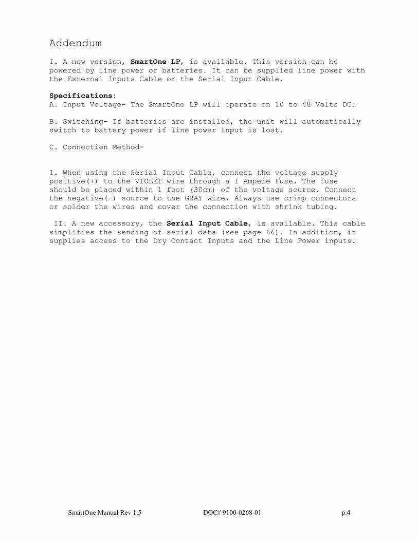
Addendum
I. A new version, SmartOne LP, is available. This version can be
powered by line power or batteries. It can be supplied line power with
the External Inputs Cable or the Serial Input Cable.
Specifications:
A. Input Voltage- The SmartOne LP will operate on 10 to 48 Volts DC.
B. Switching- If batteries are installed, the unit will automatically
switch to battery power if line power input is lost.
C. Connection Method-
1. When using the Serial Input Cable, connect the voltage supply
positive(+) to the VIOLET wire through a 1 Ampere Fuse. The fuse
should be placed within 1 foot (30cm) of the voltage source. Connect
the negative(-) source to the GRAY wire. Always use crimp connectors
or solder the wires and cover the connection with shrink tubing.
II. A new accessory, the Serial Input Cable, is available. This cable
simplifies the sending of serial data (see page 66). In addition, it
supplies access to the Dry Contact Inputs and the Line Power inputs.
SmartOne Manual Rev 1.5 DOC# 9100-0268-01 p.5
SMARTONE Basics
Overview
The SMARTONE is designed to track the position of Trailers, Cargo
Containers, Heavy Construction Equipment, Generators, Boats/Barges and any
other mobile assets. The SMARTONE also has 2 inputs to manage run time of
engines and/or other alarm inputs.
The SMARTONE processes GPS satellite signals to obtain its position in
terms of longitude and latitude and transmits this information over
Globalstar’s Simplex Satellite Network. In addition to position
information, the SMARTONE transmits other message types that include
battery status, input alarm status and diagnostic information. The
SMARTONE is configured using a computer and connection cable to
communicate these messages at certain times and/or under certain
conditions.
Modes of Operation
The SMARTONE can be configured to operate in three different Modes:
Standard Messaging Mode, Reduced Messaging Mode and Theft Recovery Mode.
Standard Messaging
In Standard Messaging Mode, the SMARTONE reports its position at regular time
intervals that are programmed during the configuration process. Standard
Messaging Mode can also be configured to utilize the SMARTONE’s internal
vibration sensor. If enabled, the SMARTONE will transmit its position at
independently configured regular time intervals when the device is In Motion.
Location messages can be programmed to be constant (Message Interval) or the
device may be configured to use up to 12 different delays in
sequence (Message-Time(s) of Day). Message Interval can be programmed
in 1 minute intervals from 35 minutes up to 45 days.
Example of Message Interval: The SMARTONE is configured to
report once every 24 hours when not in motion and every 2 hours when
In Motion. If the SMARTONE went into motion at any time of day the
Message Interval while In Motion would be every 2 hours beginning
when the SMARTONE started moving.
Example of Message-Time(s) of Day: The SMARTONE is configured
with a message time of day of 9:00am, a second message time of
day of 12:00 noon, a third message time of day of 8:00pm and
once per hour when In Motion. The SMARTONE would transmit 3
messages a day at the same configured times every day. If the
SMARTONE went In Motion it would transmit its location message
every hour.
SmartOne Manual Rev 1.5 DOC# 9100-0268-01 p.6
Usage Example: A Company is required to report the GPS locations
of their hazardous chemical containers twice a day. Based on
this requirement the Company has 2 options: set a message interval of
every 12 hours, the 12 hour internal begins when the device is
powered up or configure message times of day 12:00 noon and 12:00
midnight.
Reduced Messaging
Reduced Messaging Mode reduces the cost associated with transmitting
messages over Globalstar’s network by sending messages at a minimal
message interval when the asset is in a defined area and transmitting at
a higher message interval when the asset is changing locations. These
message intervals are set as part of the configuration process based on
the concept that repeated reporting information of the same location
when an asset has not moved from its defined area is redundant and
doesn’t provide addition usable information about its current location.
By comparing current and prior position information, the SMARTONE
determines if its location is changing. The definable area in which the
device should remain in Reduced Messaging Mode is called the Change of
Location Area and it is a square. When the SMARTONE goes outside of the
square, its location is considered to be changing or relocating.
Usage Example: A fleet operator owns 1,000 trailers. When the
trailer(s) are sitting at a depot they want a location message
once a day. They also want a message notification within 1 hour
when a trailer has left a depot. Lastly, they want a location
message every 3 hours when a trailer is moving between depots.
Based on this requirement, the fleet operator will need to set
the Change of Location Area (size of the depots where the
trailers will visit), the message interval while the trailers
are inside the Change of Location Area (1 per day), the interval
at which the SMARTONE will check its location while in a State
of Vibration and inside the Change of Location Area(1 per hour),
set the number of messages when the trailer leaves the Change of
Location Area (1 Change of Location Area Alert Message) and the
message interval while the trailers are in transit between
depots (every 3 hours).
Theft Recovery
When the SMARTONE is configured to operate in the Theft Recovery Mode,
it differentiates between authorized and unauthorized movement of an
asset. While the power to the SMARTONE is turned off, all movement of
the asset is considered authorized. When power is turned on, the
SMARTONE obtains a position from GPS satellite signals. The position is
used to set the center of the defined Change of Location Area in Theft
Recovery Mode. While in the Change of Location Area, the SMARTONE
obtains position fixes at an interval set during configuration. As long
as the SMARTONE remains within the Change of Location Area all movement
is considered to be authorized.
SmartOne Manual Rev 1.5 DOC# 9100-0268-01 p.7
Once the SMARTONE’s position is outside of the Change of Location Area, it alerts the SMARTONE to an unauthorized movement and immediately sends
a location message (Change of Location Alert Message). The SMARTONE
then continues to send location messages at a message interval set
during the configuration process until the power is turned off or the
battery is dead.
Usage Example: A construction company is working on a job site
for 1 year and wants to make sure that the generators and other
heavy equipment on site are not stolen. The company wants to
check the location of their equipment 12 times a day, every 2
hours, to confirm the asset hasn’t been stolen but only wants a
transmitted location message once per day. Based on this
requirement, the construction company will need to set the
Change of Location Area (size of the job site), the message
interval while inside the Change of Location Area (1 per day),
the interval at which the SMARTONE will check its location while
in a State of Vibration and within the Change of Location Area
(every 2 hours) and the message interval if the asset is outside
the Change of Location Area (stolen).
Inputs
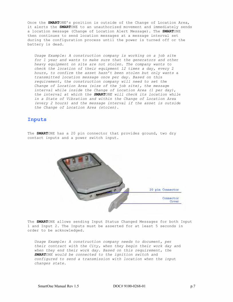
The SMARTONE has a 20 pin connector that provides ground, two dry
contact inputs and a power switch input.
The SMARTONE allows sending Input Status Changed Messages for both Input
1 and Input 2. The Inputs must be asserted for at least 5 seconds in
order to be acknowledged.
Usage Example: A construction company needs to document, per
their contract with the City, when they begin their work day and
when they end their work day. Based on this requirement, the
SMARTONE would be connected to the ignition switch and
configured to send a transmission with location when the input
changes state.
SmartOne Manual Rev 1.5 DOC# 9100-0268-01 p.8
The SMARTONE also allows the user to define the Message Interval while
the Inputs are in an Undesired State, either Opened or Closed.
Usage Example: A company has remote containers at job sites and
would like to know if a door is ajar. If a door is left ajar
the company would like a notification every 2 hours. Based on
this requirement, the SMARTONE would be connected to an open
door sensor with the Undesired Input State Message enabled and
set as Opened with a Message Interval of 2 hours.
Note: The SMARTONE uses a 5 minute "hysteresis" window to prevent sending false alarms. This means that only one status change message can be sent
during any 5 minute time window. Any subsequent status changes will be detected but not reported. Multiple status changes during any 5 minute window
will result in the transmission of incorrect trigger bits. Refer to page 52 for "Input Status Changed Message".
The SMARTONE has the ability to send an Accumulate/Count Message at a
regular configurable interval and/or based on configurable multiples of
accumulated hours and/or number of counted events or hours of vibration.
Usage Example 1: A construction company needs weekly engine run
times for their heavy equipment to manage their maintenance
scheduling. Based on this requirement, the company would
schedule a weekly Accumulate/Count Message.
Usage Example 2: A construction company wants to insure that no
equipment is ever operated beyond 400 hours without maintenance.
Based on this requirement, the company would schedule an
Accumulate/Count Message for every 400 hours of use.
The SMARTONE has the ability to send both Status Change and Undesired State
messages based on vibration.
Serial Commands
The SMARTONE uses the I/O port for unit configuration as well as interface to
remote passive and smart sensors. Two commands are provided in the unit
interface to support smart sensors. External sensors or instruments that can
format and communicate to the SMARTONE can send user data through the
SMARTONE by using these two commands.
The SMARTONE connects to smart sensors via the SMARTONE Serial Cable.
Spot offers 2 accessory cables for the SMARTONE, the USB Configuration
Cable and the Serial Cable. See Appendix E: Accessories.
SmartOne Manual Rev 1.5 DOC# 9100-0268-01 p.9
Satellite Communications
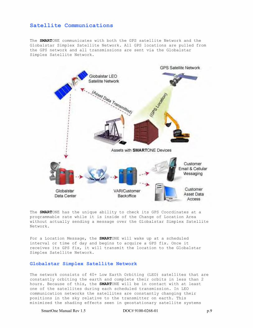
The SMARTONE communicates with both the GPS satellite Network and the
Globalstar Simplex Satellite Network. All GPS locations are pulled from
the GPS network and all transmissions are sent via the Globalstar
Simplex Satellite Network.
The SMARTONE has the unique ability to check its GPS Coordinates at a
programmable rate while it is inside of the Change of Location Area
without actually sending a message over the Globalstar Simplex Satellite
Network.
For a Location Message, the SMARTONE will wake up at a scheduled
interval or time of day and begins to acquire a GPS fix. Once it
receives its GPS fix, it will transmit the location to the Globalstar
Simplex Satellite Network.
Globalstar Simplex Satellite Network
The network consists of 40+ Low Earth Orbiting (LEO) satellites that are
constantly orbiting the earth and complete their orbits in less than 2
hours. Because of this, the SMARTONE will be in contact with at least
one of the satellites during each scheduled transmission. In LEO
communication networks the satellites are constantly changing their
positions in the sky relative to the transmitter on earth. This
minimized the shading effects seen in geostationary satellite systems
SmartOne Manual Rev 1.5 DOC# 9100-0268-01 p.10
where the mobile device must be pointed toward a specific direction in
the sky. Geostationary satellites also orbit at a much higher altitude
and move along the equator.
Messages are transmitted from the SMARTONE via the Globalstar Simplex
Satellite Network using an uplink-only connection (one-way data
transmission) and received by a Globalstar Simplex Ground Station. The
messages are then sent via an HTTP or FTP server to the internet and
received by the VAR or end customer’s back office application and
converted into actionable data.
The SMARTONE will send each message 3 times to insure that the message
has been received by the Globalstar Satellite Constellation. Once
Globalstar receives the message, any remaining duplicate messages are
ignored and discarded (VAR or end user account is only charged for 1
transmission).
Getting Started
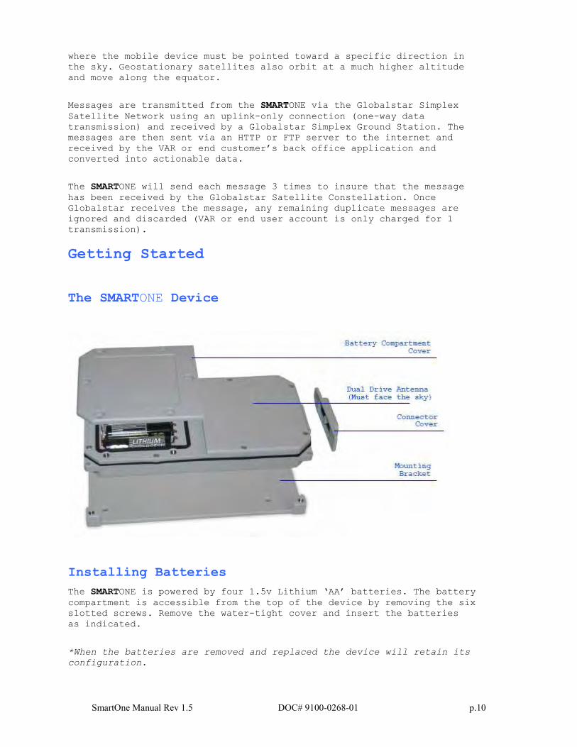
The SMARTONE Device
Installing Batteries
The SMARTONE is powered by four 1.5v Lithium ‘AA’ batteries. The battery
compartment is accessible from the top of the device by removing the six
slotted screws. Remove the water-tight cover and insert the batteries
as indicated.
*When the batteries are removed and replaced the device will retain its
configuration.
SmartOne Manual Rev 1.5 DOC# 9100-0268-01 p.11
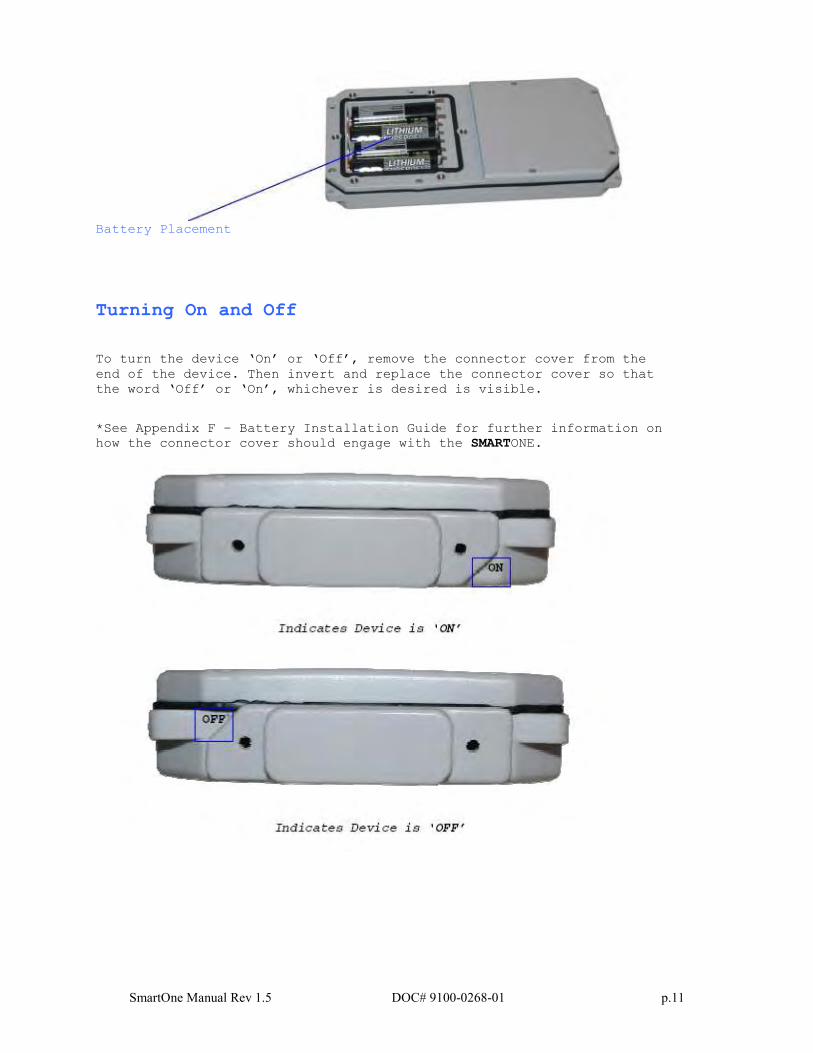
Battery Placement
Turning On and Off
To turn the device ‘On’ or ‘Off’, remove the connector cover from the
end of the device. Then invert and replace the connector cover so that
the word ‘Off’ or ‘On’, whichever is desired is visible.
*See Appendix F – Battery Installation Guide for further information on
how the connector cover should engage with the SMARTONE.
SmartOne Manual Rev 1.5 DOC# 9100-0268-01 p.12
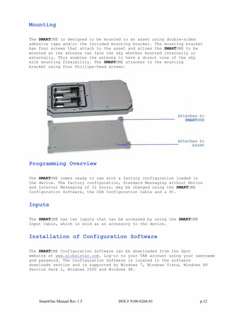
Mounting
The SMARTONE is designed to be mounted to an asset using double-sided
adhesive tape and/or the included mounting bracket. The mounting bracket
has four screws that attach to the asset and allows the SMARTONE to be
mounted so the antenna can face the sky whether mounted internally or
externally. This enables the antenna to have a direct view of the sky
with mounting flexibility. The SMARTONE attaches to the mounting
bracket using four Phillips-head screws.
Programming Overview
The SMARTONE comes ready to use with a factory configuration loaded in
the device. The factory configuration, Standard Messaging without Motion
and Interval Messaging of 12 hours, may be changed using the SMARTONE
Configuration Software, the USB Configuration Cable and a PC.
Inputs
The SMARTONE has two inputs that can be accessed by using the SMARTONE
Input Cable, which is sold as an accessory to the device.
Installation of Configuration Software
The SMARTONE Configuration Software can be downloaded from the Spot
website at www.globalstar.com. Log-in to your VAR account using your username
and password. The Configuration Software is located in the software
downloads section and is supported by Windows 7, Windows Vista, Windows XP
Service Pack 2, Windows 2000 and Windows 98.
SmartOne Manual Rev 1.5 DOC# 9100-0268-01 p.13
Connecting Devices
The SMARTONE, with batteries installed and battery cover screwed down, connects to a PC using a USB Configuration Cable. The SMARTONE
Configuration Software may be used without being connected to devices to
prepare configurations, but must be connected to a device using the USB
Configuration Cable to Program. Once the Program button has been
depressed the Configuration Cable should not be disconnected, if already
connected, from the device and/or the computer. The USB Configuration
Cable plugs into the SMARTONE when the connector cover is removed.
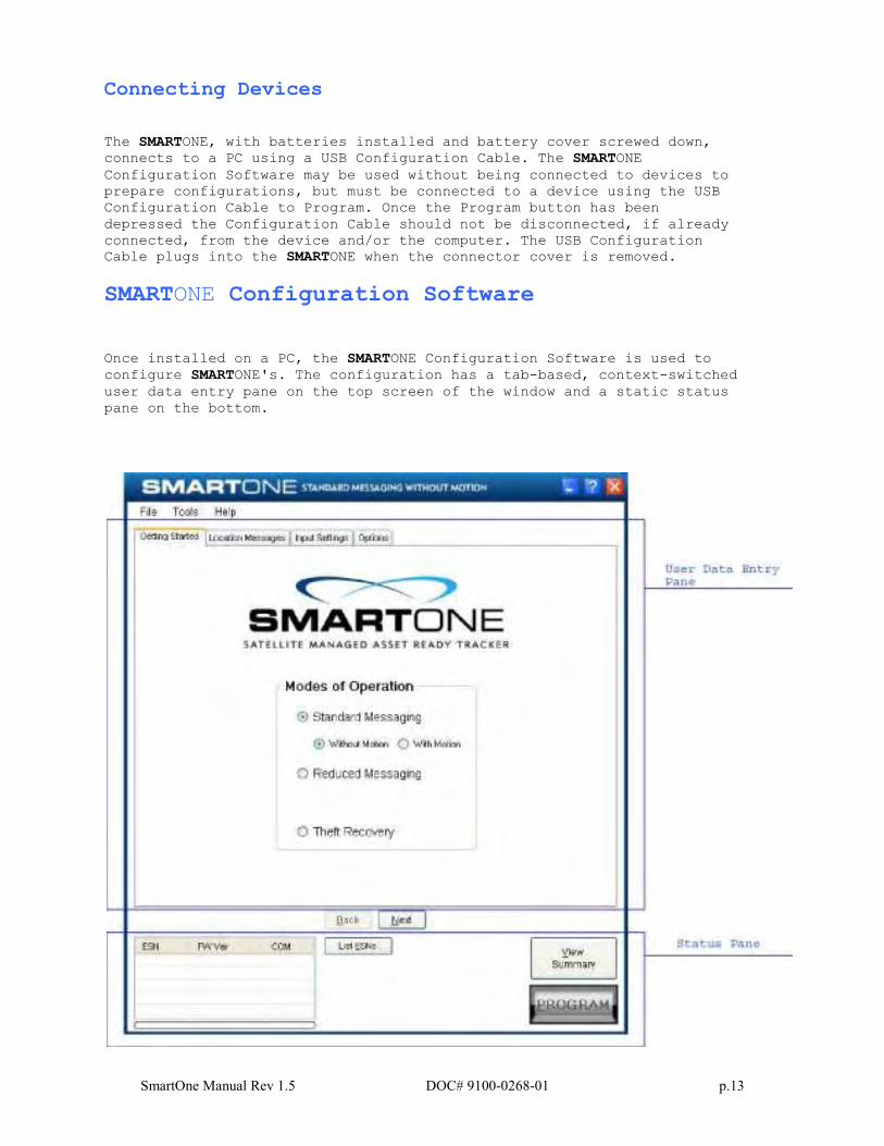
SMARTONE Configuration Software
Once installed on a PC, the SMARTONE Configuration Software is used to
configure SMARTONE's. The configuration has a tab-based, context-switched
user data entry pane on the top screen of the window and a static status
pane on the bottom.
SmartOne Manual Rev 1.5 DOC# 9100-0268-01 p.14
User Data Entry Pane
The user data entry pane contains a context-switched user entry area for
displaying and inputting configuration data. The information is
organized in pages with page manipulation provided through tabs along
the top of the pane. Selecting a tab will change the context of the
upper pane. The tabs are named to group similar functions on the same
page. The tabs will change according to the operation Mode selected.
The Back and Next buttons allow the user to move from tab to tab without
clicking on the tab name.
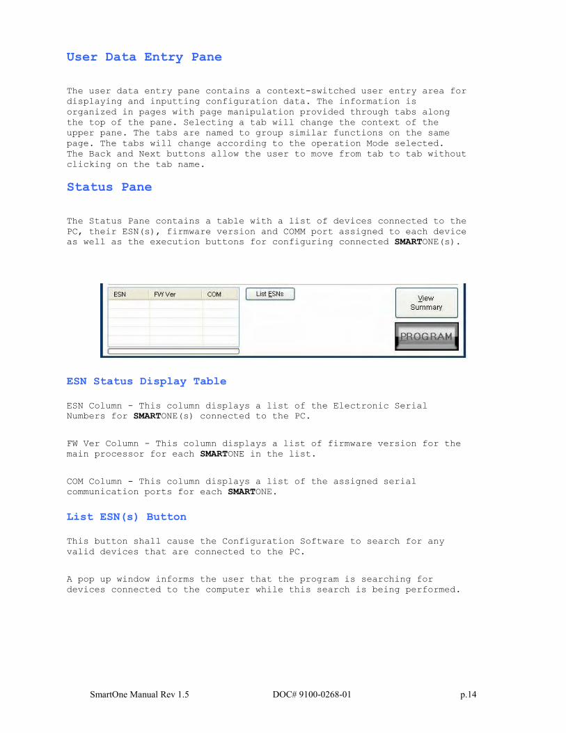
Status Pane
The Status Pane contains a table with a list of devices connected to the
PC, their ESN(s), firmware version and COMM port assigned to each device
as well as the execution buttons for configuring connected SMARTONE(s).
ESN Status Display Table
ESN Column - This column displays a list of the Electronic Serial
Numbers for SMARTONE(s) connected to the PC.
FW Ver Column - This column displays a list of firmware version for the
main processor for each SMARTONE in the list.
COM Column - This column displays a list of the assigned serial
communication ports for each SMARTONE.
List ESN(s) Button
This button shall cause the Configuration Software to search for any
valid devices that are connected to the PC.
A pop up window informs the user that the program is searching for
devices connected to the computer while this search is being performed.
SmartOne Manual Rev 1.5 DOC# 9100-0268-01 p.15
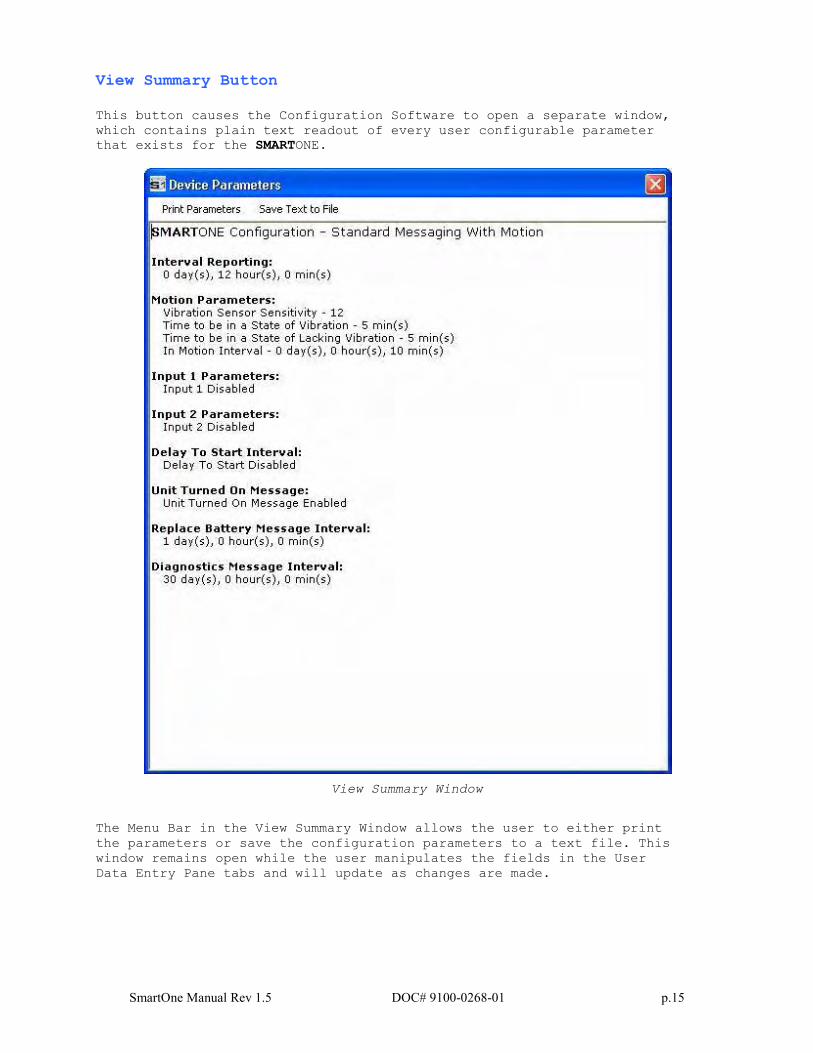
View Summary Button
This button causes the Configuration Software to open a separate window,
which contains plain text readout of every user configurable parameter
that exists for the SMARTONE.
View Summary Window
The Menu Bar in the View Summary Window allows the user to either print
the parameters or save the configuration parameters to a text file. This
window remains open while the user manipulates the fields in the User
Data Entry Pane tabs and will update as changes are made.
SmartOne Manual Rev 1.5 DOC# 9100-0268-01 p.16
Program Button
The PROGRAM button in the Status Pane is used to send the data in the
Configuration Software to the connected SMARTONE (s). The SMARTONE will
be updated with the data from the Configuration Software.
The user is queried to confirm device program before execution of the
function.
File Menu in the View Summary Window allows the user to either save the
configuration to file or print configuration.
Toolbar
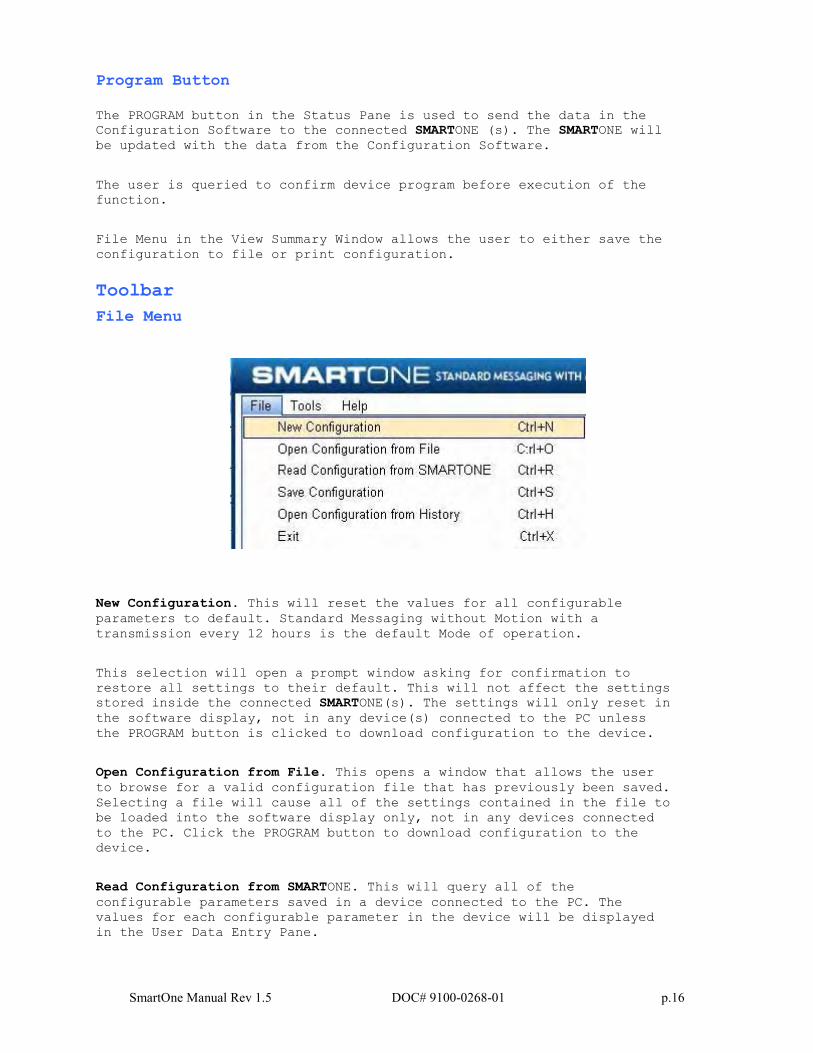
File Menu
New Configuration. This will reset the values for all configurable
parameters to default. Standard Messaging without Motion with a
transmission every 12 hours is the default Mode of operation.
This selection will open a prompt window asking for confirmation to
restore all settings to their default. This will not affect the settings
stored inside the connected SMARTONE(s). The settings will only reset in
the software display, not in any device(s) connected to the PC unless
the PROGRAM button is clicked to download configuration to the device.
Open Configuration from File. This opens a window that allows the user
to browse for a valid configuration file that has previously been saved.
Selecting a file will cause all of the settings contained in the file to
be loaded into the software display only, not in any devices connected
to the PC. Click the PROGRAM button to download configuration to the
device.
Read Configuration from SMARTONE. This will query all of the
configurable parameters saved in a device connected to the PC. The
values for each configurable parameter in the device will be displayed
in the User Data Entry Pane.
SmartOne Manual Rev 1.5 DOC# 9100-0268-01 p.17
Save Configuration. This will open a window that allows the user to
browse to a location and save all of the configuration settings to two
separate files:
The configuration file. This file is non-editable.
A text file. An ASCII format file that contains each parameter and
parameter value in a standard delimited format.
Open Configuration from History. Every time a device is successfully
programmed, the configuration will save that occurrence to a text log
file. The information stored is the ESN of the device, the local time
at which it was programmed and the actual configuration of the device.
When selected, a window opens where the user can sort by ESN or
date/time of programming and select a configuration. This loads the
selected configuration settings into the User Data Entry Pane, but not
into any device(s) connected to the PC.
Exit. This causes the program to close.
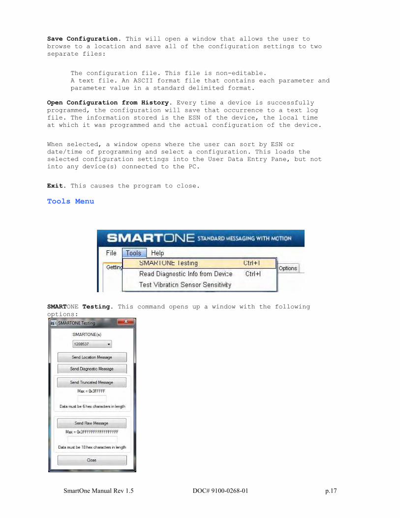
Tools Menu
SMARTONE Testing. This command opens up a window with the following
options:
SmartOne Manual Rev 1.5 DOC# 9100-0268-01 p.18
Send Location Message - causes the SMARTONE connected to the
COM port to obtain a GPS fix and send a Location Message.
Send Diagnostic Message – causes the SMARTONE connected to
send diagnostic information including battery status, GPS
average search time, GPS fails and number of transmissions
since last diagnostic message.
Send Data w/GPS Message - causes the SMARTONE to seek a GPS
location, and then send a Truncated SMARTONE message (type 1).
The hex-character data in the text box below the command will be
appended to the GPS data and sent.
Send Data w/o GPS message - causes the SMARTONE to send the first
8 bytes of data in the text box above the command as the payload
for the Raw Payload Message (type 2). The hex-character data in
the text box above the command will be sent instead of the normal
SMARTONE position data.
Close – causes the pop up window to close.
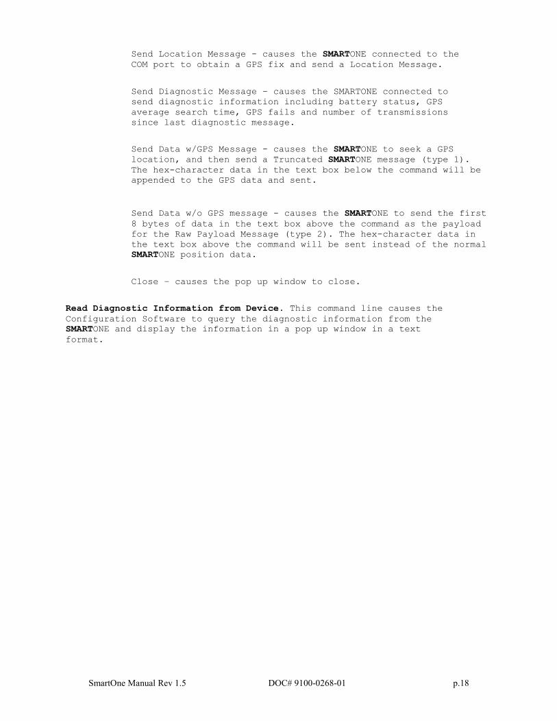
Read Diagnostic Information from Device. This command line causes the
Configuration Software to query the diagnostic information from the
SMARTONE and display the information in a pop up window in a text
format.
SmartOne Manual Rev 1.5 DOC# 9100-0268-01 p.19
There are two menu options available in the pop up window:
Print Diagnostic –prints the diagnostic information.
Save Text to File – Opens a window, which allows the user to browse
for a location and save the diagnostic information in a text file.
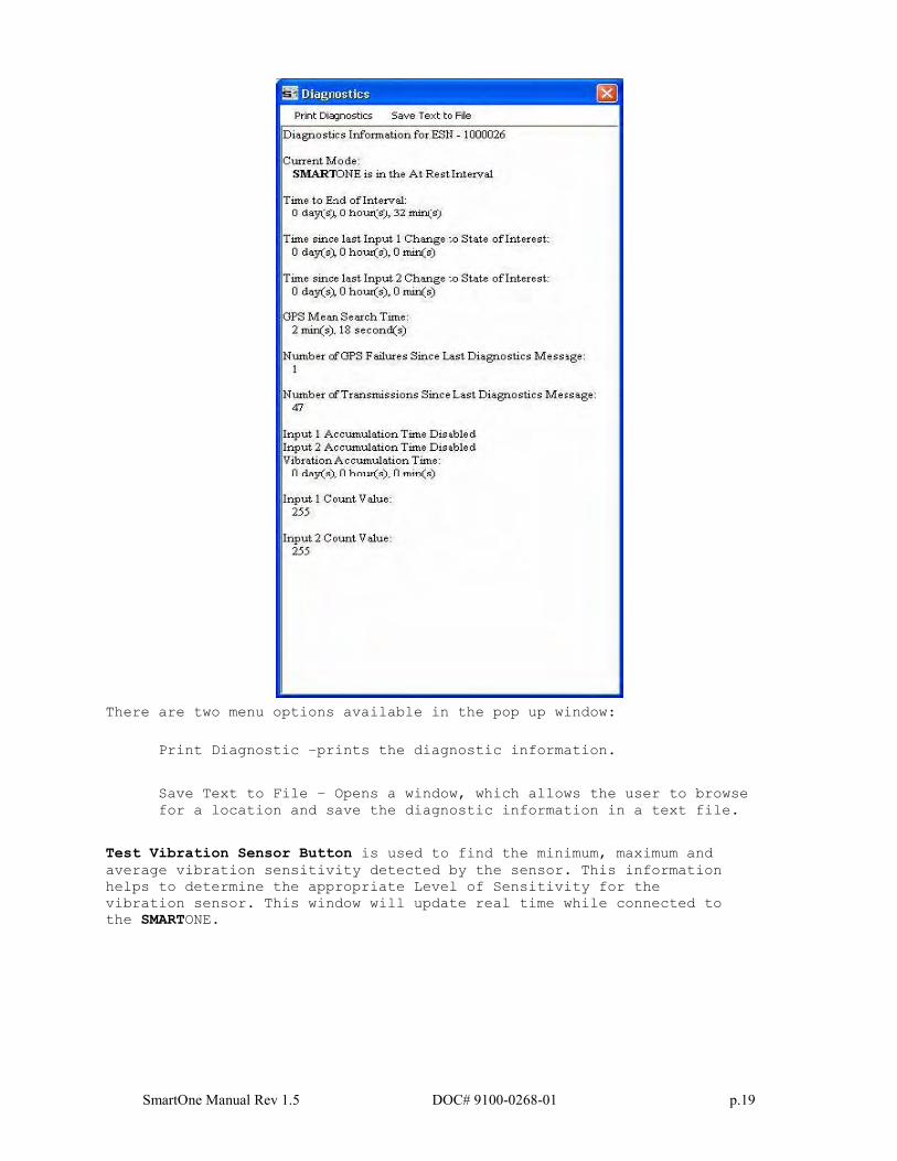
Test Vibration Sensor Button is used to find the minimum, maximum and
average vibration sensitivity detected by the sensor. This information
helps to determine the appropriate Level of Sensitivity for the
vibration sensor. This window will update real time while connected to
the SMARTONE.
SmartOne Manual Rev 1.5 DOC# 9100-0268-01 p.20
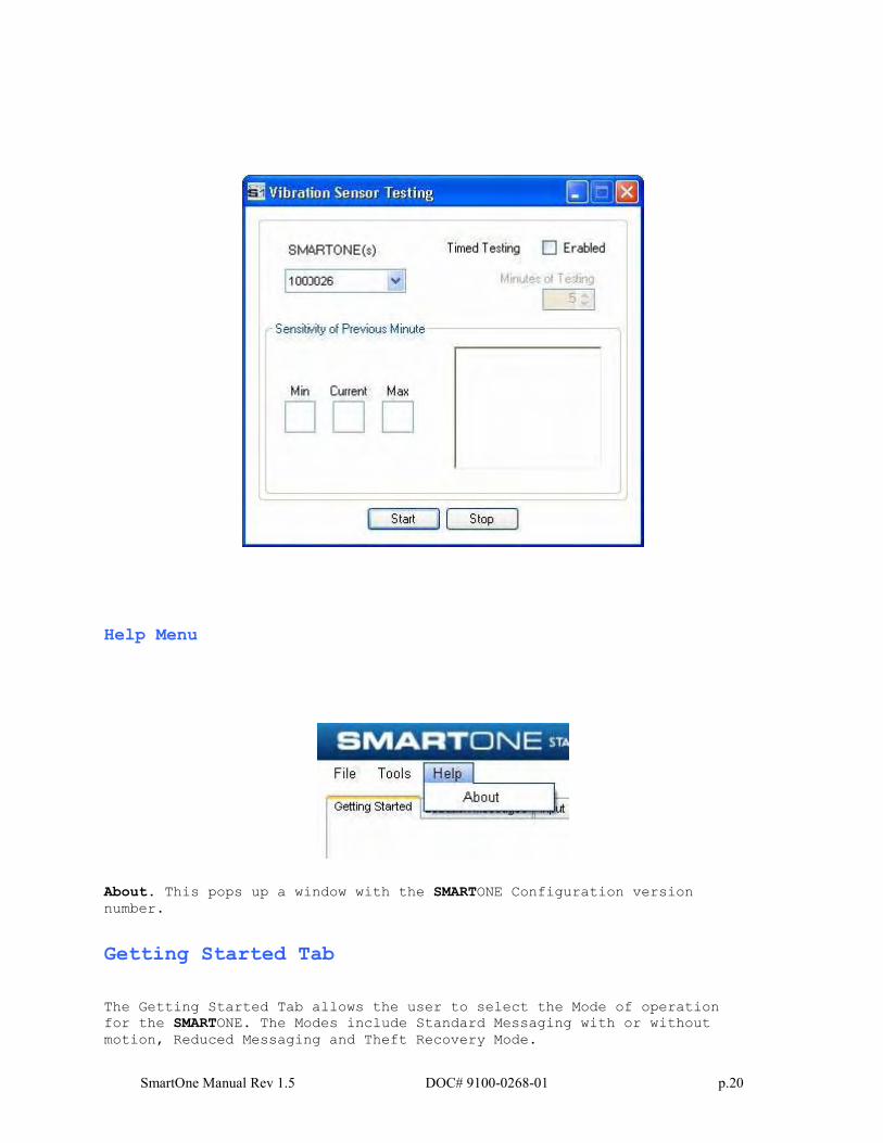
Help Menu
About. This pops up a window with the SMARTONE Configuration version
number.
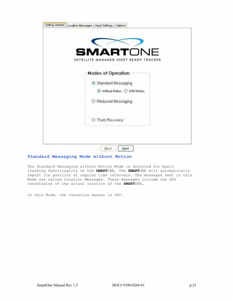
Getting Started Tab
The Getting Started Tab allows the user to select the Mode of operation
for the SMARTONE. The Modes include Standard Messaging with or without
motion, Reduced Messaging and Theft Recovery Mode.
SmartOne Manual Rev 1.5 DOC# 9100-0268-01 p.21
Standard Messaging Mode without Motion
The Standard Messaging without Motion Mode is selected for basic
tracking functionality on the SMARTONE. The SMARTONE will automatically
report its position at regular time intervals. The messages sent in this
Mode are called Location Messages. These messages include the GPS
coordinates of the actual location of the SMARTONE.
In this Mode, the vibration sensor is OFF.
SmartOne Manual Rev 1.5 DOC# 9100-0268-01 p.22
Standard Messaging Mode with Motion
The Standard Messaging with Motion Mode is selected for basic tracking
functionality with motion detection capabilities. The user defines the
motion parameters for each application including the Level of
Sensitivity of the vibration sensor, Time to be in a State of Vibration
and Time to be in a State of Lacking Vibration. The SMARTONE can be set
to report at a different rate, Message Interval while In Motion,
compared to the Location Message Interval.
Reduced Messaging Mode
The Reduced Messaging Mode is ideal for asset management with reduced
messaging capability of the SMARTONE. The SMARTONE creates a Change of Location Area of configurable size around the device. If the SMARTONE
stays within its Change of Location Area, the number of transmissions
will be reduced.
When the SMARTONE leaves the Change of Location Area and returned to a
State of Lacking Vibration a new Change of Location Area is created
around the SMARTONE.
Theft Recovery Mode
The Theft Recovery Mode is ideal for assets that are high-risk for
theft. In this Mode, the SMARTONE creates a Change of Location Area
around its location when powered. The size of the Change of Location
Area is a configurable parameter equal to the distance the device must
move to be considered outside the Change of Location Area. If outside
the Change of Location Area, the SMARTONE goes into recovery Mode,
transmitting frequent messages until the asset is recovered. The message
interval in recovery Mode is a configurable parameter; however, the
default value is 10 minutes.
SmartOne Manual Rev 1.5 DOC# 9100-0268-01 p.23
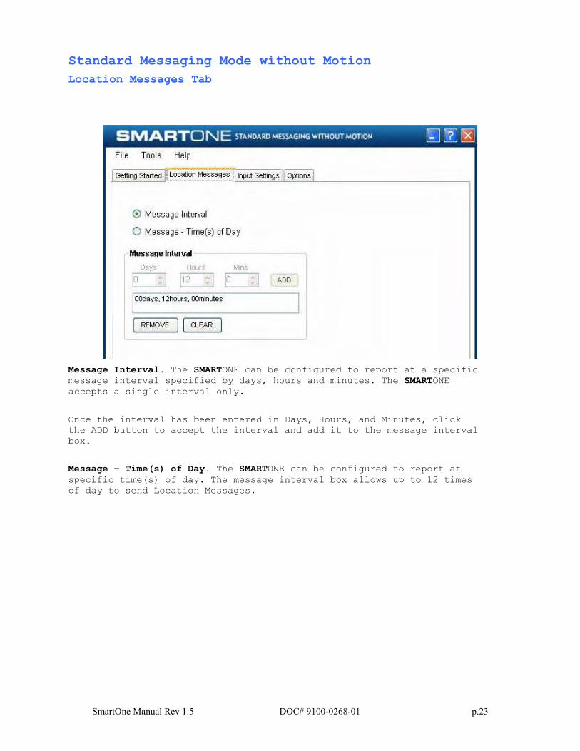
Standard Messaging Mode without Motion
Location Messages Tab
Message Interval. The SMARTONE can be configured to report at a specific
message interval specified by days, hours and minutes. The SMARTONE
accepts a single interval only.
Once the interval has been entered in Days, Hours, and Minutes, click
the ADD button to accept the interval and add it to the message interval
box.
Message – Time(s) of Day. The SMARTONE can be configured to report at
specific time(s) of day. The message interval box allows up to 12 times
of day to send Location Messages.
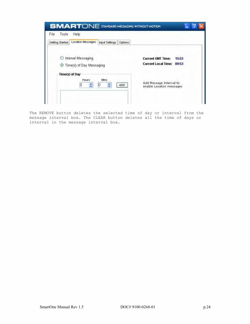
SmartOne Manual Rev 1.5 DOC# 9100-0268-01 p.24
The REMOVE button deletes the selected time of day or interval from the
message interval box. The CLEAR button deletes all the time of days or
interval in the message interval box.
SmartOne Manual Rev 1.5 DOC# 9100-0268-01 p.25
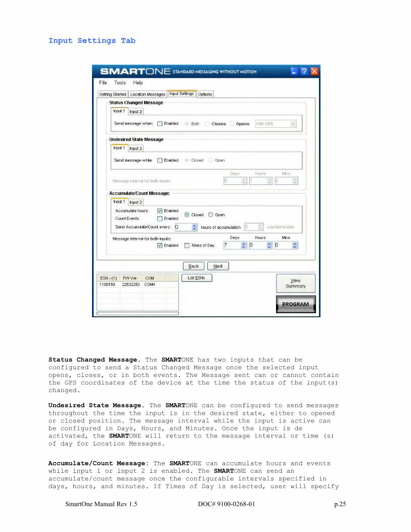
Input Settings Tab
Status Changed Message. The SMARTONE has two inputs that can be
configured to send a Status Changed Message once the selected input
opens, closes, or in both events. The Message sent can or cannot contain
the GPS coordinates of the device at the time the status of the input(s)
changed.
Undesired State Message. The SMARTONE can be configured to send messages
throughout the time the input is in the desired state, either to opened
or closed position. The message interval while the input is active can
be configured in Days, Hours, and Minutes. Once the input is de
activated, the SMARTONE will return to the message interval or time (s)
of day for Location Messages.
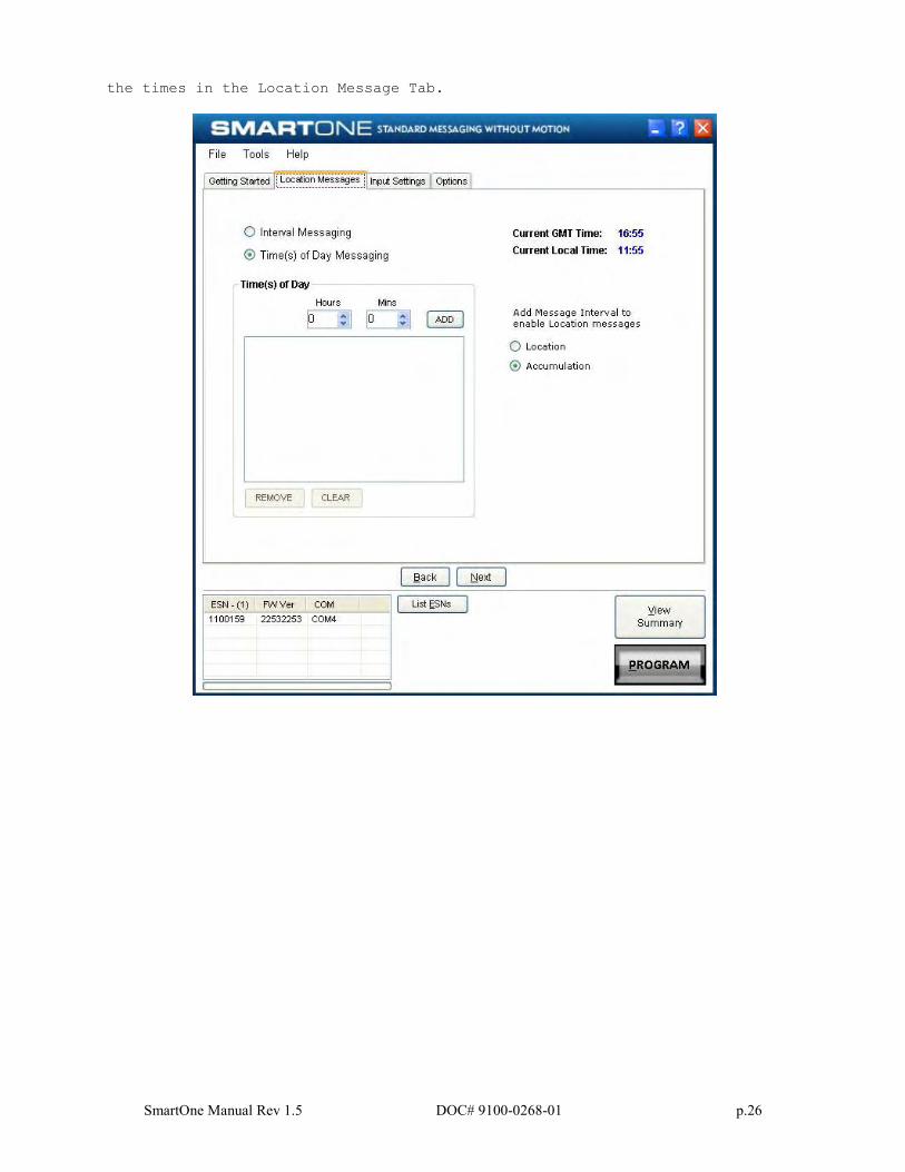
Accumulate/Count Message: The SMARTONE can accumulate hours and events while input 1 or input 2 is enabled. The SMARTONE can send an
accumulate/count message once the configurable intervals specified in
days, hours, and minutes. If Times of Day is selected, user will specify
SmartOne Manual Rev 1.5 DOC# 9100-0268-01 p.26
the times in the Location Message Tab.
SmartOne Manual Rev 1.5 DOC# 9100-0268-01 p.27
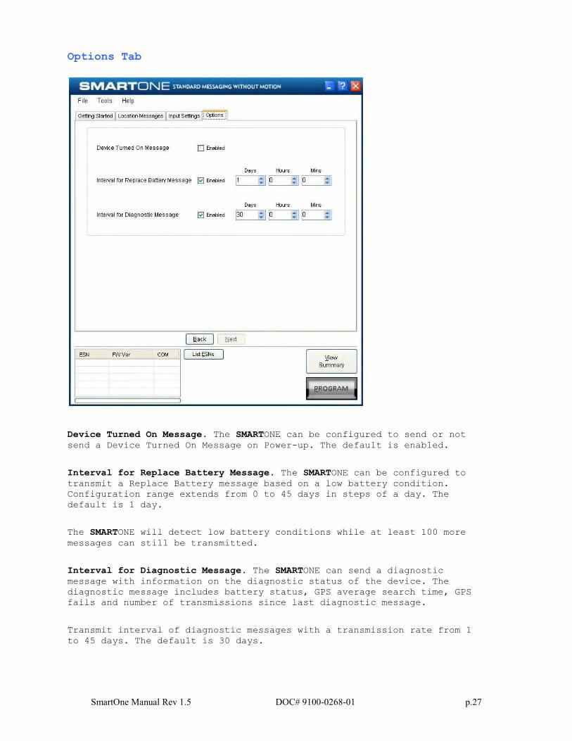
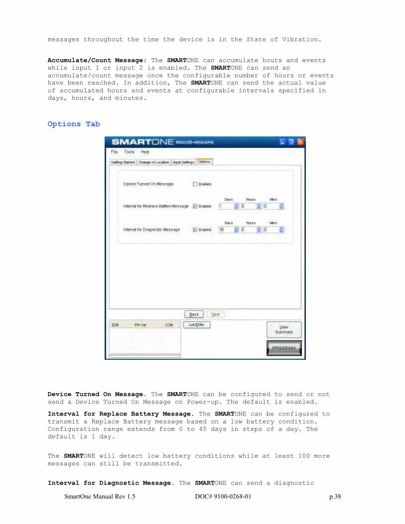
Options Tab
Device Turned On Message. The SMARTONE can be configured to send or not
send a Device Turned On Message on Power-up. The default is enabled.
Interval for Replace Battery Message. The SMARTONE can be configured to
transmit a Replace Battery message based on a low battery condition.
Configuration range extends from 0 to 45 days in steps of a day. The
default is 1 day.
The SMARTONE will detect low battery conditions while at least 100 more
messages can still be transmitted.
Interval for Diagnostic Message. The SMARTONE can send a diagnostic
message with information on the diagnostic status of the device. The
diagnostic message includes battery status, GPS average search time, GPS
fails and number of transmissions since last diagnostic message.
Transmit interval of diagnostic messages with a transmission rate from 1
to 45 days. The default is 30 days.
SmartOne Manual Rev 1.5 DOC# 9100-0268-01 p.28
Standard Messaging Mode with Motion
Motion Settings Tab
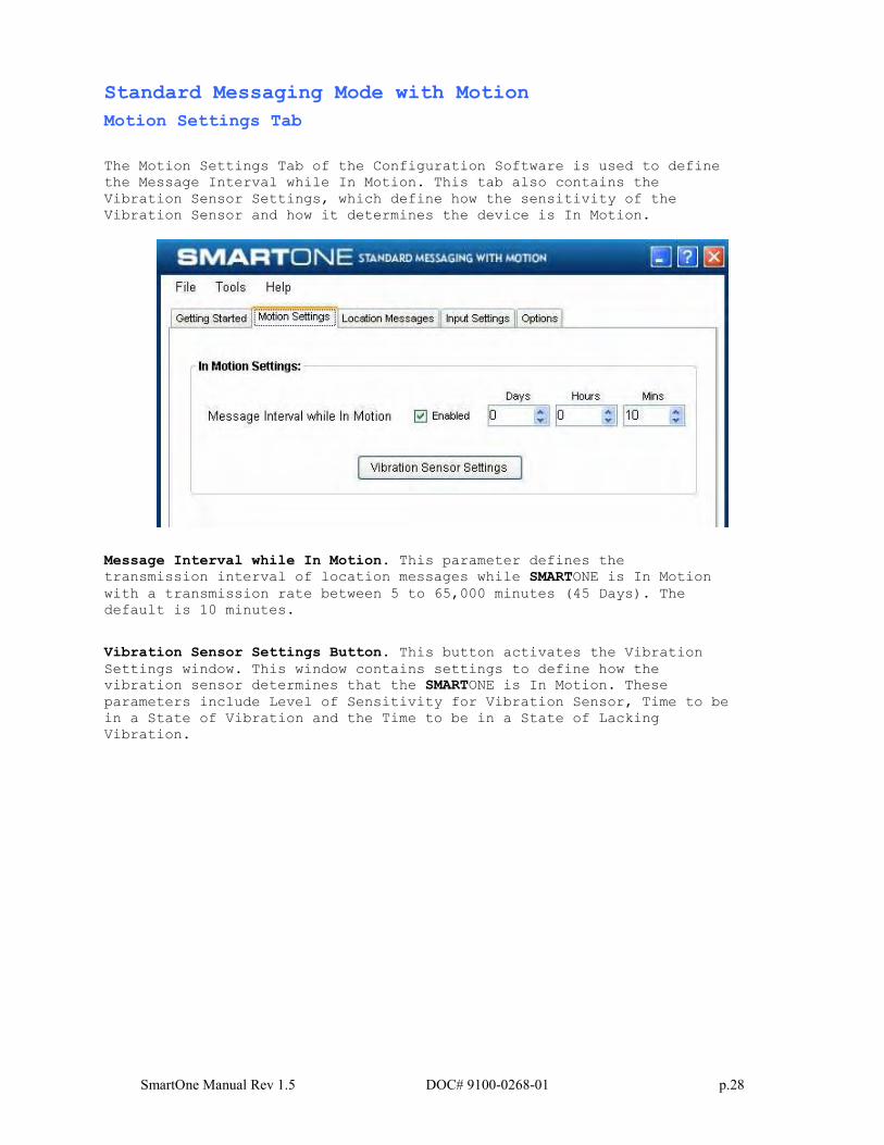
The Motion Settings Tab of the Configuration Software is used to define
the Message Interval while In Motion. This tab also contains the
Vibration Sensor Settings, which define how the sensitivity of the
Vibration Sensor and how it determines the device is In Motion.
Message Interval while In Motion. This parameter defines the transmission interval of location messages while SMARTONE is In Motion
with a transmission rate between 5 to 65,000 minutes (45 Days). The
default is 10 minutes.
Vibration Sensor Settings Button. This button activates the Vibration
Settings window. This window contains settings to define how the
vibration sensor determines that the SMARTONE is In Motion. These
parameters include Level of Sensitivity for Vibration Sensor, Time to be
in a State of Vibration and the Time to be in a State of Lacking
Vibration.
SmartOne Manual Rev 1.5 DOC# 9100-0268-01 p.29
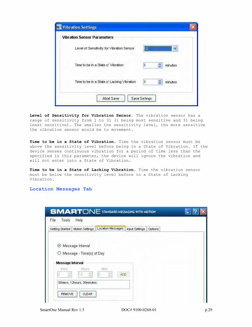
Level of Sensitivity for Vibration Sensor. The vibration sensor has a
range of sensitivity from 1 to 31 (1 being most sensitive and 31 being
least sensitive). The smaller the sensitivity level, the more sensitive
the vibration sensor would be to movement.
Time to be in a State of Vibration. Time the vibration sensor must be
above the sensitivity level before being in a State of Vibration. If the
device senses continuous vibration for a period of time less than the
specified in this parameter, the device will ignore the vibration and
will not enter into a State of Vibration.
Time to be in a State of Lacking Vibration. Time the vibration sensor
must be below the sensitivity level before in a State of Lacking
Vibration.
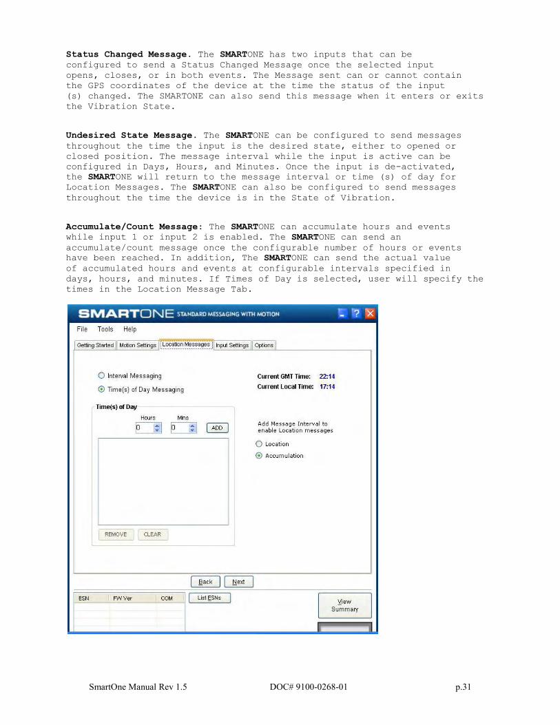
Location Messages Tab
SmartOne Manual Rev 1.5 DOC# 9100-0268-01 p.30
Message Interval. The SMARTONE can be configured to report at a specific message interval specified by days, hours and minutes. The SMARTONE
accepts a single interval only.
Once the interval has been entered in Days, Hours, and Minutes, the ADD
button will accept the interval and add it to the message interval box.
Message – Time(s) of Day. The SMARTONE can be configured to report at
specific time (s) of day. The message interval box allows up to 12 times
of day to send Location Messages.
The Remove button deletes the selected time of day or interval from the
message interval box. The Clear button deletes all the time of days or
interval in the message interval box.
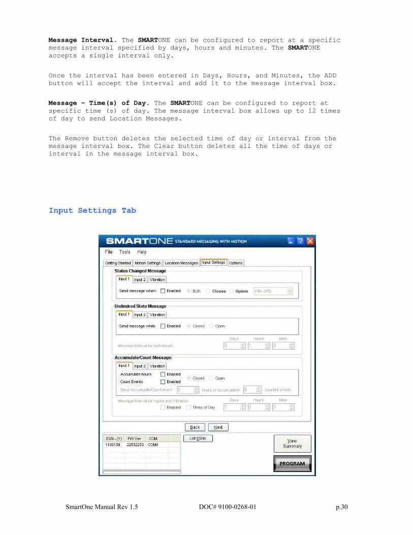
Input Settings Tab
SmartOne Manual Rev 1.5 DOC# 9100-0268-01 p.31
Status Changed Message. The SMARTONE has two inputs that can be
configured to send a Status Changed Message once the selected input
opens, closes, or in both events. The Message sent can or cannot contain
the GPS coordinates of the device at the time the status of the input
(s) changed. The SMARTONE can also send this message when it enters or exits
the Vibration State.
Undesired State Message. The SMARTONE can be configured to send messages
throughout the time the input is the desired state, either to opened or
closed position. The message interval while the input is active can be
configured in Days, Hours, and Minutes. Once the input is de-activated,
the SMARTONE will return to the message interval or time (s) of day for Location Messages. The SMARTONE can also be configured to send messages
throughout the time the device is in the State of Vibration.
Accumulate/Count Message: The SMARTONE can accumulate hours and events while input 1 or input 2 is enabled. The SMARTONE can send an
accumulate/count message once the configurable number of hours or events
have been reached. In addition, The SMARTONE can send the actual value
of accumulated hours and events at configurable intervals specified in
days, hours, and minutes. If Times of Day is selected, user will specify the
times in the Location Message Tab.
SmartOne Manual Rev 1.5 DOC# 9100-0268-01 p.32
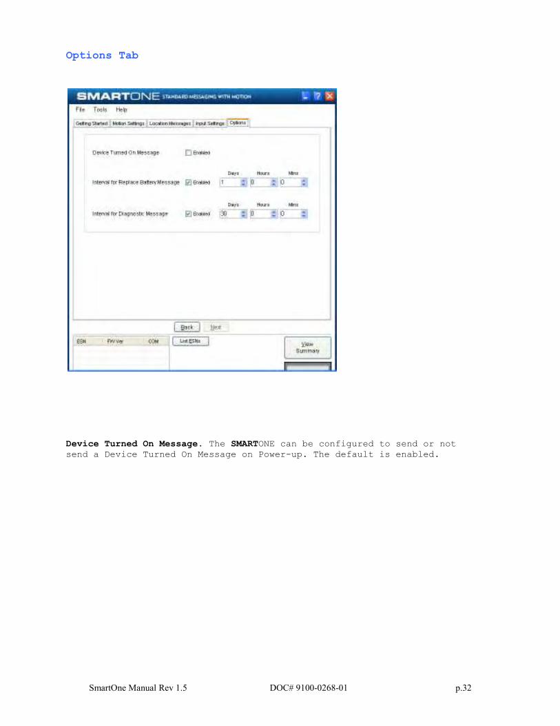
Options Tab
Device Turned On Message. The SMARTONE can be configured to send or not
send a Device Turned On Message on Power-up. The default is enabled.
SmartOne Manual Rev 1.5 DOC# 9100-0268-01 p.33
Interval for Replace Battery Message. The SMARTONE can be configured to
transmit a Replace Battery message based on a low battery condition.
Configuration range extends from 0 to 45 days in steps of a day. The
default is 1 day.
The SMARTONE will detect low battery conditions while at least 100 more
messages can still be transmitted.
Interval for Diagnostic Message. The SMARTONE can send a diagnostic
message with information on the diagnostic status of the device. The
diagnostic message includes battery status, GPS average search time, GPS
fails and number of transmissions since last diagnostic message.
Transmit interval of diagnostic messages with a transmission rate from 1
to 45 days. The default is 30 days.
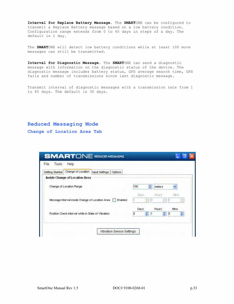
Reduced Messaging Mode
Change of Location Area Tab
SmartOne Manual Rev 1.5 DOC# 9100-0268-01 p.34
Inside Change of Location Area
The parameters in this section define the functionality of the device
while inside its Change of Location Area while in Reduced Messaging
Mode.
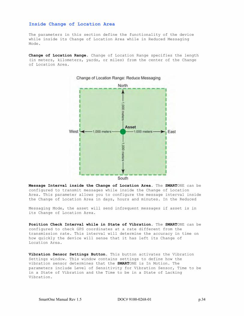
Change of Location Range. Change of Location Range specifies the length
(in meters, kilometers, yards, or miles) from the center of the Change
of Location Area.
Message Interval inside the Change of Location Area. The SMARTONE can be
configured to transmit messages while inside the Change of Location
Area. This parameter allows you to configure the message interval inside
the Change of Location Area in days, hours and minutes. In the Reduced
Messaging Mode, the asset will send infrequent messages if asset is in
its Change of Location Area.
Position Check Interval while in State of Vibration. The SMARTONE can be
configured to check GPS coordinates at a rate different from the
transmission rate. This interval will determine the accuracy in time on
how quickly the device will sense that it has left its Change of
Location Area.
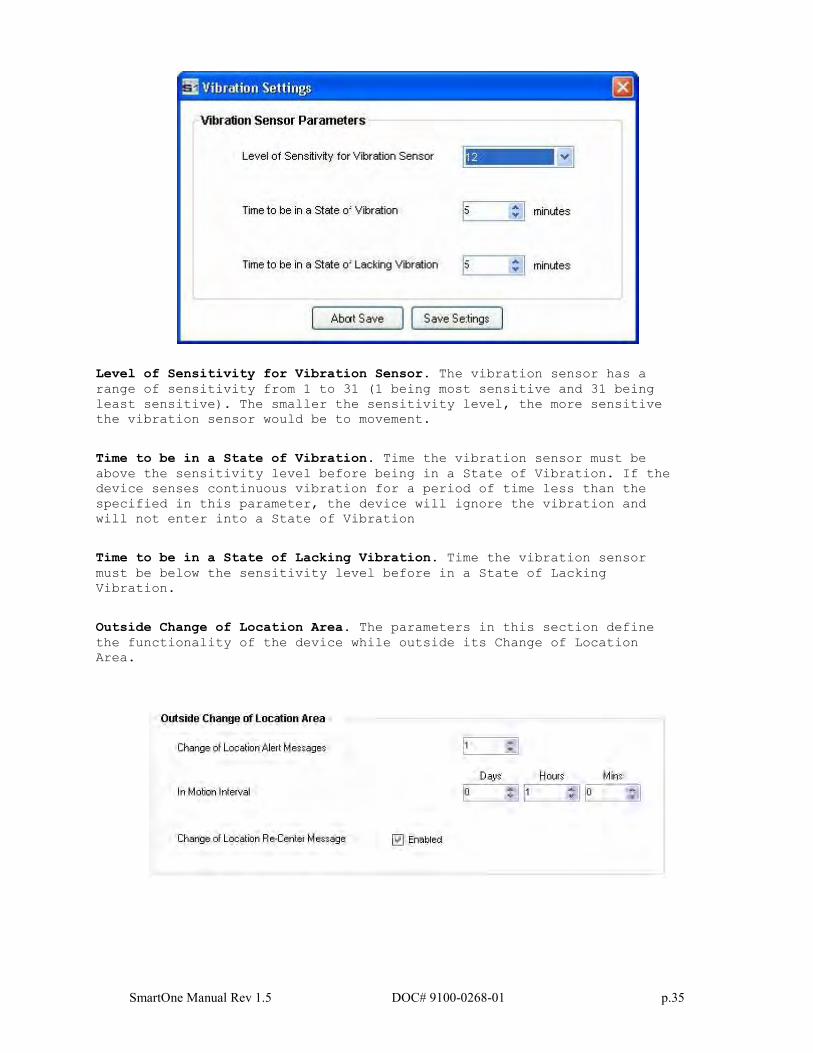
Vibration Sensor Settings Button. This button activates the Vibration
Settings window. This window contains settings to define how the
vibration sensor determines that the SMARTONE is In Motion. The
parameters include Level of Sensitivity for Vibration Sensor, Time to be
in a State of Vibration and the Time to be in a State of Lacking
Vibration.
SmartOne Manual Rev 1.5 DOC# 9100-0268-01 p.35
Level of Sensitivity for Vibration Sensor. The vibration sensor has a
range of sensitivity from 1 to 31 (1 being most sensitive and 31 being
least sensitive). The smaller the sensitivity level, the more sensitive
the vibration sensor would be to movement.
Time to be in a State of Vibration. Time the vibration sensor must be
above the sensitivity level before being in a State of Vibration. If the
device senses continuous vibration for a period of time less than the
specified in this parameter, the device will ignore the vibration and
will not enter into a State of Vibration
Time to be in a State of Lacking Vibration. Time the vibration sensor
must be below the sensitivity level before in a State of Lacking
Vibration.
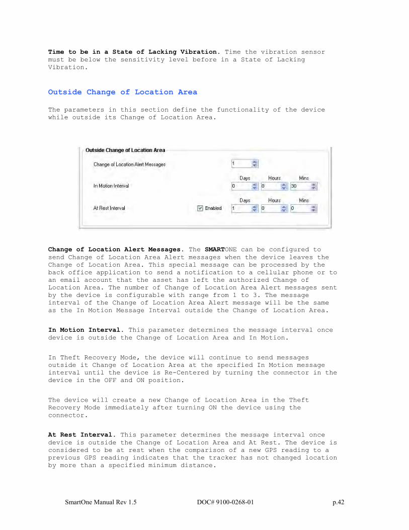
Outside Change of Location Area. The parameters in this section define
the functionality of the device while outside its Change of Location
Area.
SmartOne Manual Rev 1.5 DOC# 9100-0268-01 p.36
Change of Location Alert Message. The SMARTONE can be configured to send
Change of Location Area Alert messages when the device leaves the Change
of Location Area. This special message can be processed by the back
office application to send a notification to a cellular phone or to an
email account that the asset has left the Change of Location Area. The
number of Change of Location Area Alert messages sent by the device is
configurable with range from 0 to 3. The message interval of the Change
of Location Area Alert message will be the same as the In Motion Message
Interval outside the Change of Location Area.
In Motion Interval. This parameter determines the message interval once
device is outside the Change of Location Area and In Motion.
Change of Location Re-Center Message. Once the SMARTONE creates a new
Change of Location Area after entering the At Rest State, it can or
cannot send a Re-Center Message.
SmartOne Manual Rev 1.5 DOC# 9100-0268-01 p.37
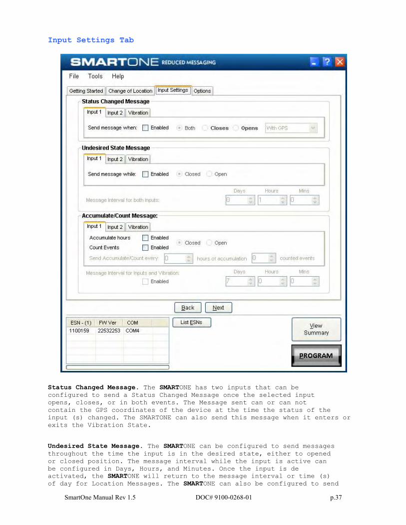
Input Settings Tab
Status Changed Message. The SMARTONE has two inputs that can be
configured to send a Status Changed Message once the selected input
opens, closes, or in both events. The Message sent can or can not
contain the GPS coordinates of the device at the time the status of the
input (s) changed. The SMARTONE can also send this message when it enters or
exits the Vibration State.
Undesired State Message. The SMARTONE can be configured to send messages
throughout the time the input is in the desired state, either to opened
or closed position. The message interval while the input is active can
be configured in Days, Hours, and Minutes. Once the input is de
activated, the SMARTONE will return to the message interval or time (s)
of day for Location Messages. The SMARTONE can also be configured to send
SmartOne Manual Rev 1.5 DOC# 9100-0268-01 p.38
messages throughout the time the device is in the State of Vibration.
Accumulate/Count Message: The SMARTONE can accumulate hours and events
while input 1 or input 2 is enabled. The SMARTONE can send an
accumulate/count message once the configurable number of hours or events
have been reached. In addition, The SMARTONE can send the actual value
of accumulated hours and events at configurable intervals specified in
days, hours, and minutes. Options Tab
Device Turned On Message. The SMARTONE can be configured to send or not
send a Device Turned On Message on Power-up. The default is enabled.
Interval for Replace Battery Message. The SMARTONE can be configured to
transmit a Replace Battery message based on a low battery condition.
Configuration range extends from 0 to 45 days in steps of a day. The
default is 1 day.
The SMARTONE will detect low battery conditions while at least 100 more
messages can still be transmitted.
Interval for Diagnostic Message. The SMARTONE can send a diagnostic
SmartOne Manual Rev 1.5 DOC# 9100-0268-01 p.39
message with information on the diagnostic status of the device. The
diagnostic message includes battery status, GPS average search time, GPS
fails and number of transmissions since last diagnostic message.
Transmit interval of diagnostic messages with a transmission rate from 1
to 45 days. The default is 30 days.
SmartOne Manual Rev 1.5 DOC# 9100-0268-01 p.40
Theft Recovery Mode
Change of Location Area Tab
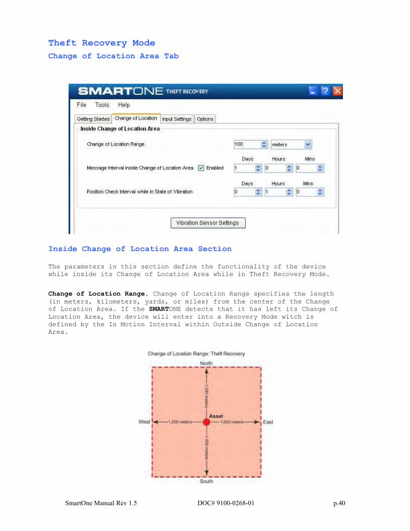
Inside Change of Location Area Section
The parameters in this section define the functionality of the device
while inside its Change of Location Area while in Theft Recovery Mode.
Change of Location Range. Change of Location Range specifies the length
(in meters, kilometers, yards, or miles) from the center of the Change
of Location Area. If the SMARTONE detects that it has left its Change of
Location Area, the device will enter into a Recovery Mode witch is
defined by the In Motion Interval within Outside Change of Location
Area.
SmartOne Manual Rev 1.5 DOC# 9100-0268-01 p.41
Message Interval inside the Change of Location Area. The SMARTONE can be
configured to transmit messages while inside its Change of Location
Area. This parameter allows you to configure the message interval inside
the Change of Location Area in days, hours and minutes. In Theft
Recovery Mode, the asset will send infrequent messages, user
configurable interval, if asset is in its Change of Location Area.
Position Check Interval while in State of Vibration. The SMARTONE can be
configured to check GPS coordinates at a rate different from the
transmission rate. This interval will determine the accuracy in time on
how quickly the device will sense that it has left its authorized Change
of Location Area.
The SMARTONE has the ability to get GPS fixes without transmitting the
information to Globalstar Simples network. It uses the information to
confirm if it is inside its Change of Location Area.
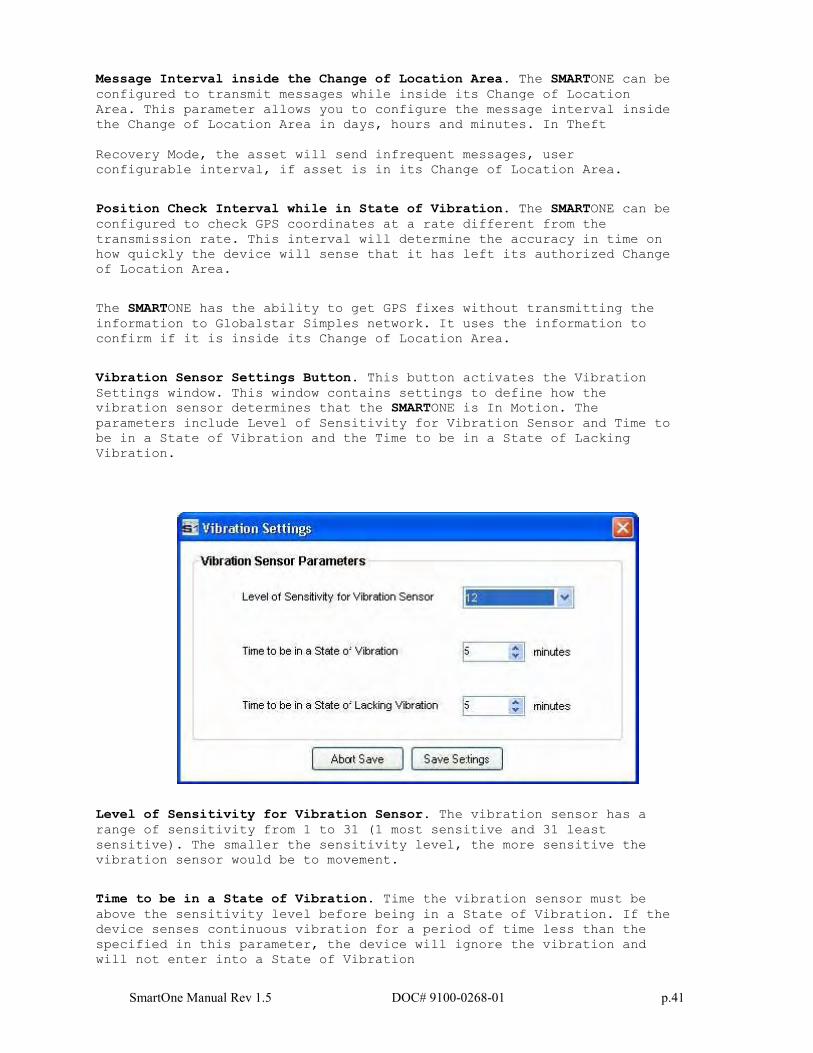
Vibration Sensor Settings Button. This button activates the Vibration
Settings window. This window contains settings to define how the
vibration sensor determines that the SMARTONE is In Motion. The
parameters include Level of Sensitivity for Vibration Sensor and Time to
be in a State of Vibration and the Time to be in a State of Lacking
Vibration.
Level of Sensitivity for Vibration Sensor. The vibration sensor has a
range of sensitivity from 1 to 31 (1 most sensitive and 31 least
sensitive). The smaller the sensitivity level, the more sensitive the
vibration sensor would be to movement.
Time to be in a State of Vibration. Time the vibration sensor must be
above the sensitivity level before being in a State of Vibration. If the
device senses continuous vibration for a period of time less than the
specified in this parameter, the device will ignore the vibration and
will not enter into a State of Vibration
SmartOne Manual Rev 1.5 DOC# 9100-0268-01 p.42
Time to be in a State of Lacking Vibration. Time the vibration sensor
must be below the sensitivity level before in a State of Lacking
Vibration.
Outside Change of Location Area
The parameters in this section define the functionality of the device
while outside its Change of Location Area.
Change of Location Alert Messages. The SMARTONE can be configured to
send Change of Location Area Alert messages when the device leaves the
Change of Location Area. This special message can be processed by the
back office application to send a notification to a cellular phone or to
an email account that the asset has left the authorized Change of
Location Area. The number of Change of Location Area Alert messages sent
by the device is configurable with range from 1 to 3. The message
interval of the Change of Location Area Alert message will be the same
as the In Motion Message Interval outside the Change of Location Area.
In Motion Interval. This parameter determines the message interval once
device is outside the Change of Location Area and In Motion.
In Theft Recovery Mode, the device will continue to send messages
outside it Change of Location Area at the specified In Motion message
interval until the device is Re-Centered by turning the connector in the
device in the OFF and ON position.
The device will create a new Change of Location Area in the Theft
Recovery Mode immediately after turning ON the device using the
connector.
At Rest Interval. This parameter determines the message interval once
device is outside the Change of Location Area and At Rest. The device is
considered to be at rest when the comparison of a new GPS reading to a
previous GPS reading indicates that the tracker has not changed location
by more than a specified minimum distance.
SmartOne Manual Rev 1.5 DOC# 9100-0268-01 p.43
Input Settings Tab
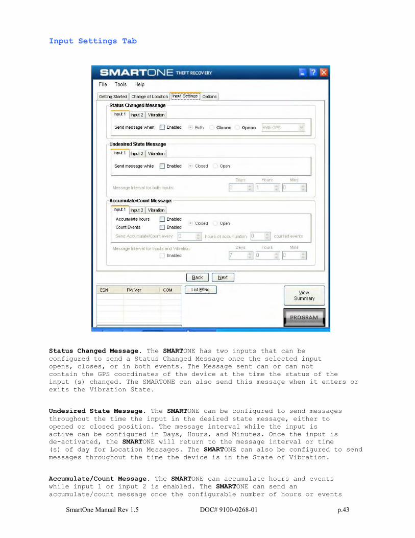
Status Changed Message. The SMARTONE has two inputs that can be
configured to send a Status Changed Message once the selected input
opens, closes, or in both events. The Message sent can or can not
contain the GPS coordinates of the device at the time the status of the
input (s) changed. The SMARTONE can also send this message when it enters or
exits the Vibration State.
Undesired State Message. The SMARTONE can be configured to send messages
throughout the time the input in the desired state message, either to
opened or closed position. The message interval while the input is
active can be configured in Days, Hours, and Minutes. Once the input is
de-activated, the SMARTONE will return to the message interval or time
(s) of day for Location Messages. The SMARTONE can also be configured to send
messages throughout the time the device is in the State of Vibration.
Accumulate/Count Message. The SMARTONE can accumulate hours and events
while input 1 or input 2 is enabled. The SMARTONE can send an
accumulate/count message once the configurable number of hours or events
SmartOne Manual Rev 1.5 DOC# 9100-0268-01 p.44
have been reached. In addition, The SMARTONE can send the actual value
of accumulated hours and events at configurable intervals specified in
days, hours, and minutes.
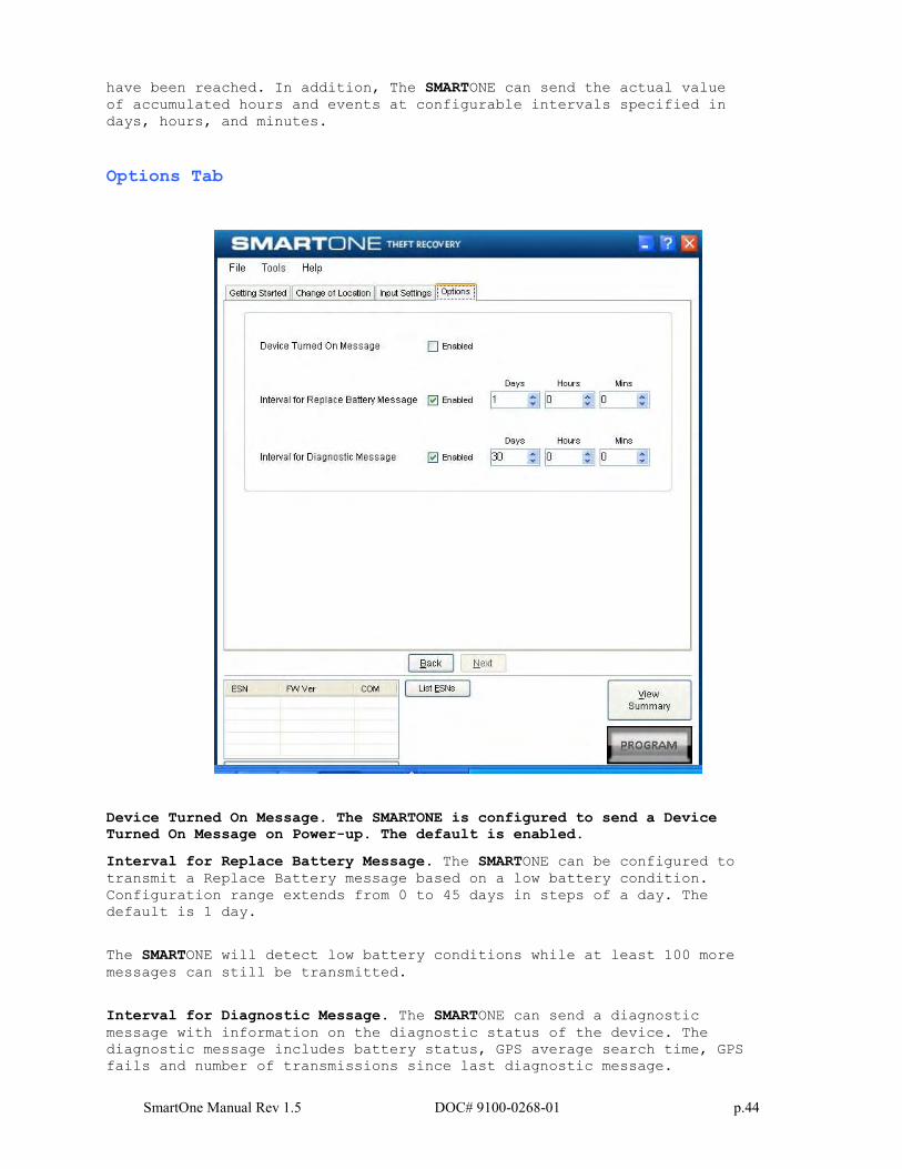
Options Tab
Device Turned On Message. The SMARTONE is configured to send a Device Turned On Message on Power-up. The default is enabled.
Interval for Replace Battery Message. The SMARTONE can be configured to
transmit a Replace Battery message based on a low battery condition.
Configuration range extends from 0 to 45 days in steps of a day. The
default is 1 day.
The SMARTONE will detect low battery conditions while at least 100 more
messages can still be transmitted.
Interval for Diagnostic Message. The SMARTONE can send a diagnostic
message with information on the diagnostic status of the device. The
diagnostic message includes battery status, GPS average search time, GPS
fails and number of transmissions since last diagnostic message.

SmartOne Manual Rev 1.5 DOC# 9100-0268-01 p.45
Transmit interval of diagnostic messages with a transmission rate from 1
to 45 days. The default is 30 days.
Messages
The SMARTONE produces on-air messages conforming to the Globalstar
specified format.
The data being communicated to the end user is contained entirely in the
72 bit (9 byte) field.
This section will describe the use of the 9 byte user information
segment for communicating the range of information that the SMARTONE is
able to convey to the user.
User information is sometimes referred to as the message payload.
Basic User Information
Global Message Type
Bits 0 and 1 in the first byte of the user data define the Global
Message Type; there are four total global types. Types 0 and 3 are
applicable to the function and features of the SMARTONE, type 1 and 2 are
user defined message types.
Type 0: Standard Message: All of the various message types
that contain Latitude and Longitude data that are transmitted
by the SMARTONE will be of this type.
Type 1: Truncated Message: This message type provides for up to 2
bytes plus 6 bits of user data to be appended to the status byte
and GPS location information.
Type 2: Raw Message: This message type provides for up to 8 bytes
plus 6 bits of user data.
Type 3: Non Standard Message: This is the message type that
covers the category “none of the above”. The SMARTONE will use
this message type for messages that do not contain Latitude
and Longitude data. Smart One message types which fall into this
category include Accumulate/Count messages, Diagnostic messages,
Contact Service Provider messages and Low Battery messages.
SmartOne Manual Rev 1.5 DOC# 9100-0268-01 p.46
Type 0 Message Class
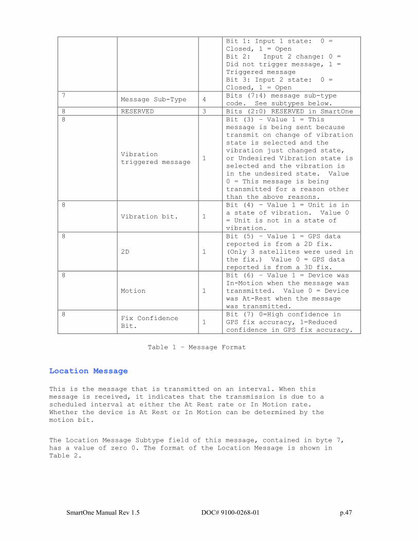
Message Format
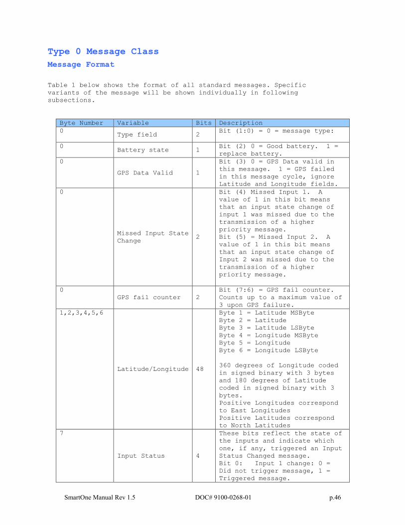
Table 1 below shows the format of all standard messages. Specific
variants of the message will be shown individually in following
subsections.
Byte Number Variable Bits Description
0 Type field 2
Bit (1:0) = 0 = message type:
0 Battery state 1
Bit (2) 0 = Good battery. 1 =
replace battery.
0
GPS Data Valid 1
Bit (3) 0 = GPS Data valid in
this message. 1 = GPS failed
in this message cycle, ignore
Latitude and Longitude fields.
0
Missed Input State
Change 2
Bit (4) Missed Input 1. A
value of 1 in this bit means
that an input state change of
input 1 was missed due to the
transmission of a higher
priority message.
Bit (5) = Missed Input 2. A
value of 1 in this bit means
that an input state change of
Input 2 was missed due to the
transmission of a higher
priority message.
0
GPS fail counter 2
Bit (7:6) = GPS fail counter.
Counts up to a maximum value of
3 upon GPS failure.
1,2,3,4,5,6
Latitude/Longitude 48
Byte 1 = Latitude MSByte
Byte 2 = Latitude
Byte 3 = Latitude LSByte
Byte 4 = Longitude MSByte
Byte 5 = Longitude
Byte 6 = Longitude LSByte
360 degrees of Longitude coded
in signed binary with 3 bytes
and 180 degrees of Latitude
coded in signed binary with 3
bytes.
Positive Longitudes correspond
to East Longitudes
Positive Latitudes correspond
to North Latitudes
7
Input Status 4
These bits reflect the state of
the inputs and indicate which
one, if any, triggered an Input
Status Changed message.
Bit 0: Input 1 change: 0 =
Did not trigger message, 1 =
Triggered message.
SmartOne Manual Rev 1.5 DOC# 9100-0268-01 p.47
Bit 1: Input 1 state: 0 =
Closed, 1 = Open
Bit 2: Input 2 change: 0 =
Did not trigger message, 1 =
Triggered message
Bit 3: Input 2 state: 0 =
Closed, 1 = Open
7 Message Sub-Type 4
Bits (7:4) message sub-type
code. See subtypes below.
8 RESERVED 3 Bits (2:0) RESERVED in SmartOne
8
Vibration
triggered message 1
Bit (3) – Value 1 = This
message is being sent because
transmit on change of vibration
state is selected and the
vibration just changed state,
or Undesired Vibration state is
selected and the vibration is
in the undesired state. Value
0 = This message is being
transmitted for a reason other
than the above reasons.
8
Vibration bit. 1
Bit (4) – Value 1 = Unit is in
a state of vibration. Value 0
= Unit is not in a state of
vibration.
8
2D 1
Bit (5) – Value 1 = GPS data
reported is from a 2D fix.
(Only 3 satellites were used in
the fix.) Value 0 = GPS data
reported is from a 3D fix.
8
Motion 1
Bit (6) – Value 1 = Device was
In-Motion when the message was
transmitted. Value 0 = Device
was At-Rest when the message
was transmitted.
8 Fix Confidence
Bit. 1
Bit (7) 0=High confidence in
GPS fix accuracy, 1=Reduced
confidence in GPS fix accuracy.
Table 1 – Message Format
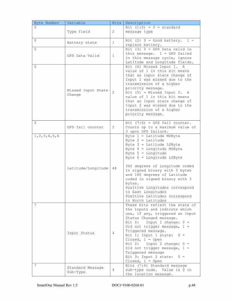
Location Message
This is the message that is transmitted on an interval. When this
message is received, it indicates that the transmission is due to a
scheduled interval at either the At Rest rate or In Motion rate.
Whether the device is At Rest or In Motion can be determined by the
motion bit.
The Location Message Subtype field of this message, contained in byte 7,
has a value of zero 0. The format of the Location Message is shown in
Table 2.
SmartOne Manual Rev 1.5 DOC# 9100-0268-01 p.48
Byte Number Variable Bits Description
0
Type field 2
Bit (1:0) = 0 = standard
message type
0 Battery state 1
Bit (2) 0 = Good battery. 1 =
replace battery.
0
GPS Data Valid 1
Bit (3) 0 = GPS Data valid in
this message. 1 = GPS failed
in this message cycle, ignore
Latitude and Longitude fields.
0
Missed Input State
Change 2
Bit (4) Missed Input 1. A
value of 1 in this bit means
that an input state change of
Input 1 was missed due to the
transmission of a higher
priority message.
Bit (5) = Missed Input 2. A
value of 1 in this bit means
that an input state change of
Input 2 was missed due to the
transmission of a higher
priority message.
0
GPS fail counter 2
Bit (7:6) = GPS fail counter.
Counts up to a maximum value of
3 upon GPS failure.
1,2,3,4,5,6
Latitude/Longitude 48
Byte 1 = Latitude MSByte
Byte 2 = Latitude
Byte 3 = Latitude LSByte
Byte 4 = Longitude MSByte
Byte 5 = Longitude
Byte 6 = Longitude LSByte
360 degrees of Longitude coded
in signed binary with 3 bytes
and 180 degrees of Latitude
coded in signed binary with 3
bytes.
Positive Longitudes correspond
to East Longitudes
Positive Latitudes correspond
to North Latitudes
7
Input Status 4
These bits reflect the state of
the inputs and indicate which
one, if any, triggered an Input
Status Changed message.
Bit 0: Input 1 change: 0 =
Did not trigger message, 1 =
Triggered message.
Bit 1: Input 1 state: 0 =
Closed, 1 = Open
Bit 2: Input 2 change: 0 =
Did not trigger message, 1 =
Triggered message
Bit 3: Input 2 state: 0 =
Closed, 1 = Open
7 Standard Message
Sub-Type 4
Bits (7:4) Standard message
sub-type code. Value is 0 in
the location message.
SmartOne Manual Rev 1.5 DOC# 9100-0268-01 p.49
8 RESERVED 3 Bits (2:0) RESERVED in SmartOne
8
Vibration
triggered message 1
Bit (3) – Value 1 = This
message is being sent because
transmit on change of vibration
state is selected and the
vibration just changed state,
or Undesired Vibration state is
selected and the vibration is
in the undesired state. Value
0 = This message is being
transmitted for a reason other
than the above reasons.
8
Vibration bit. 1
Bit (4) – Value 1 = Unit is in
a state of vibration. Value 0
= Unit is not in a state of
vibration.
8
2D 1
Bit (5) – Value 1 = GPS data
reported is from a 2D fix.
(Only 3 satellites were used in
the fix.) Value 0 = GPS data
reported is from a 3D fix.
8
Motion 1
Bit (6) – Value 1 = Device was
In-Motion when the message was
transmitted. Value 0 = Device
was At-Rest when the message
was transmitted.
8 Fix Confidence
Bit. 1
Bit (7) 0=High confidence in
GPS fix accuracy, 1=Reduced
confidence in GPS fix accuracy.
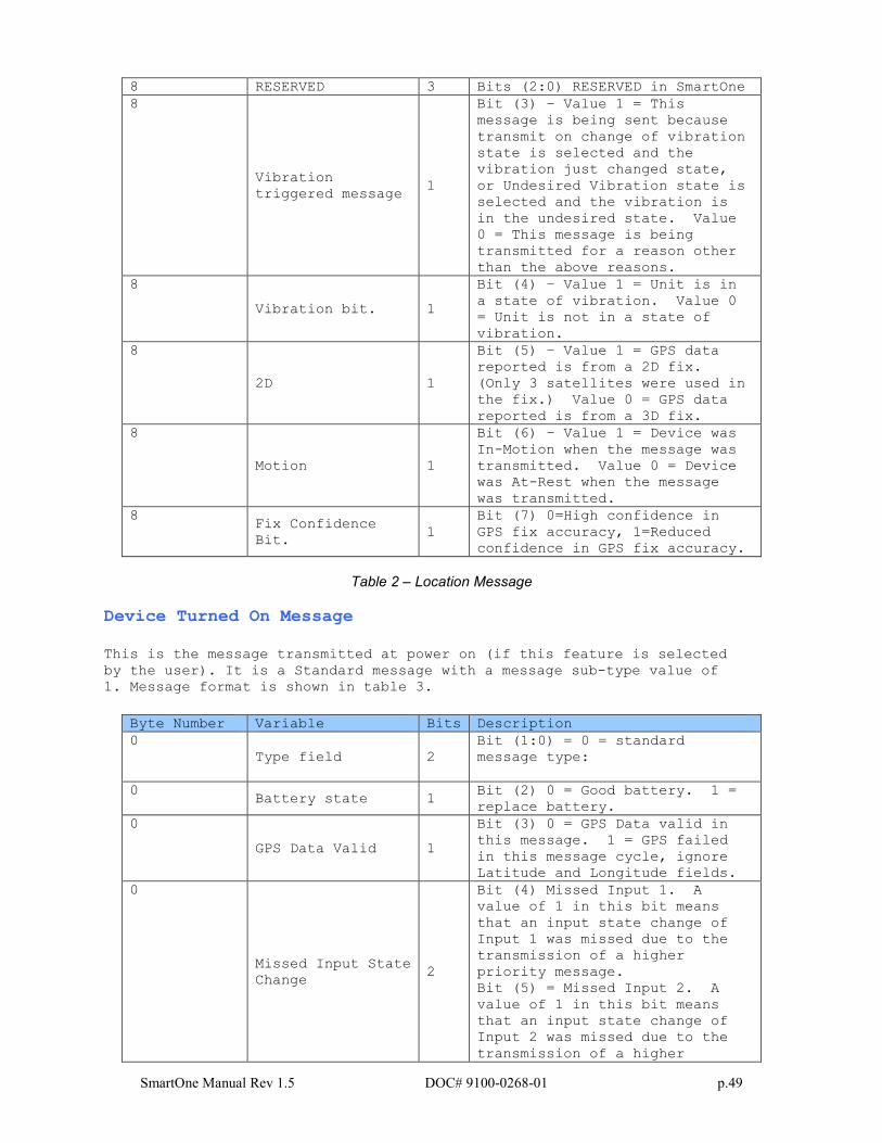
Table 2 – Location Message
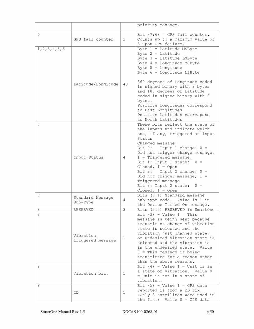
Device Turned On Message
This is the message transmitted at power on (if this feature is selected
by the user). It is a Standard message with a message sub-type value of
1. Message format is shown in table 3.
Byte Number Variable Bits Description
0
Type field 2
Bit (1:0) = 0 = standard
message type:
0 Battery state 1
Bit (2) 0 = Good battery. 1 =
replace battery.
0
GPS Data Valid 1
Bit (3) 0 = GPS Data valid in
this message. 1 = GPS failed
in this message cycle, ignore
Latitude and Longitude fields.
0
Missed Input State
Change 2
Bit (4) Missed Input 1. A
value of 1 in this bit means
that an input state change of
Input 1 was missed due to the
transmission of a higher
priority message.
Bit (5) = Missed Input 2. A
value of 1 in this bit means
that an input state change of
Input 2 was missed due to the
transmission of a higher
SmartOne Manual Rev 1.5 DOC# 9100-0268-01 p.50
priority message.
0
GPS fail counter 2
Bit (7:6) = GPS fail counter.
Counts up to a maximum value of
3 upon GPS failure.
1,2,3,4,5,6
Latitude/Longitude 48
Byte 1 = Latitude MSByte
Byte 2 = Latitude
Byte 3 = Latitude LSByte
Byte 4 = Longitude MSByte
Byte 5 = Longitude
Byte 6 = Longitude LSByte
360 degrees of Longitude coded
in signed binary with 3 bytes
and 180 degrees of Latitude
coded in signed binary with 3
bytes.
Positive Longitudes correspond
to East Longitudes
Positive Latitudes correspond
to North Latitudes
7
Input Status 4
These bits reflect the state of
the inputs and indicate which
one, if any, triggered an Input
Status
Changed message.
Bit 0: Input 1 change: 0 =
Did not trigger change message,
1 = Triggered message.
Bit 1: Input 1 state: 0 =
Closed, 1 = Open
Bit 2: Input 2 change: 0 =
Did not trigger message, 1 =
Triggered message
Bit 3: Input 2 state: 0 =
Closed, 1 = Open
7 Standard Message
Sub-Type 4
Bits (7:4) Standard message
sub-type code. Value is 1 in
the Device Turned On message.
8 RESERVED 3 Bits (2:0) RESERVED in SmartOne
8
Vibration
triggered message 1
Bit (3) – Value 1 = This
message is being sent because
transmit on change of vibration
state is selected and the
vibration just changed state,
or Undesired Vibration state is
selected and the vibration is
in the undesired state. Value
0 = This message is being
transmitted for a reason other
than the above reasons.
8
Vibration bit. 1
Bit (4) – Value 1 = Unit is in
a state of vibration. Value 0
= Unit is not in a state of
vibration.
8
2D 1
Bit (5) – Value 1 = GPS data
reported is from a 2D fix.
(Only 3 satellites were used in
the fix.) Value 0 = GPS data
SmartOne Manual Rev 1.5 DOC# 9100-0268-01 p.51
reported is from a 3D fix.
8
Motion 1
Bit (6) – Value 1 = Device was
In-Motion when the message was
transmitted. Value 0 = Device
was At-Rest when the message
was transmitted.
8 Fix Confidence
Bit. 1
Bit (7) 0=High confidence in
GPS fix accuracy, 1=Reduced
confidence in GPS fix accuracy.
Table 3 - Device Turned On message
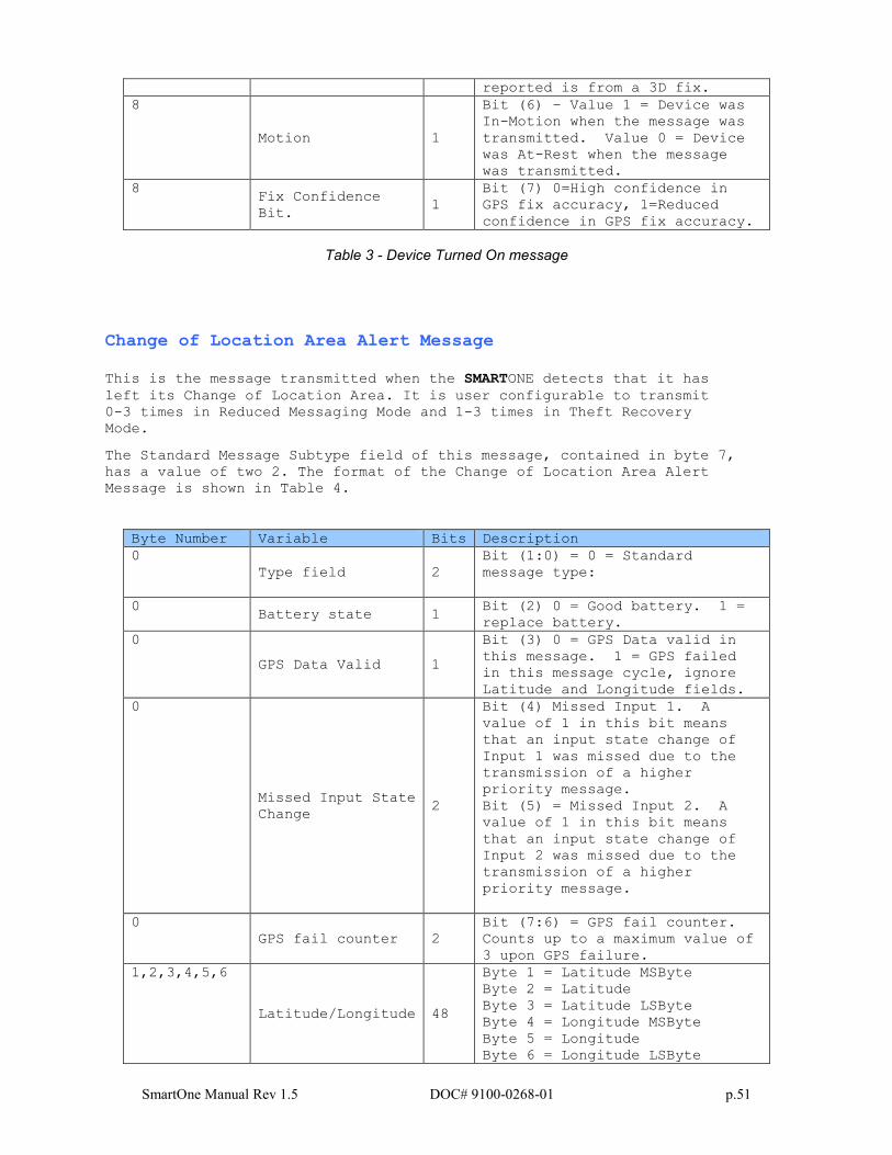
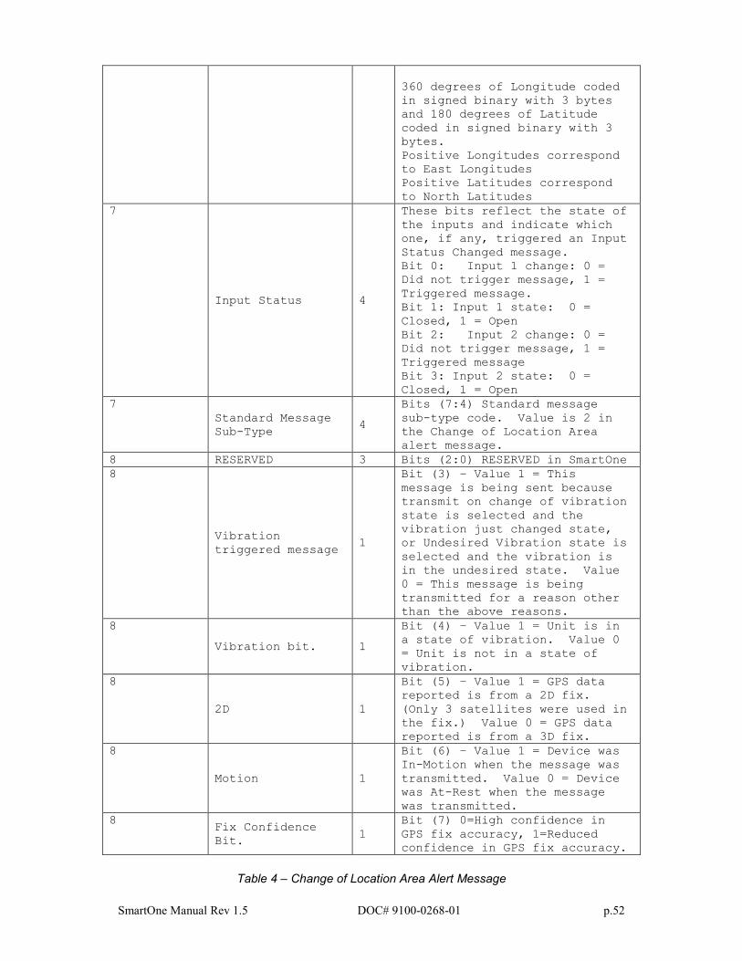
Change of Location Area Alert Message
This is the message transmitted when the SMARTONE detects that it has
left its Change of Location Area. It is user configurable to transmit
0-3 times in Reduced Messaging Mode and 1-3 times in Theft Recovery
Mode.
The Standard Message Subtype field of this message, contained in byte 7,
has a value of two 2. The format of the Change of Location Area Alert
Message is shown in Table 4.
Byte Number Variable Bits Description
0
Type field 2
Bit (1:0) = 0 = Standard
message type:
0 Battery state 1
Bit (2) 0 = Good battery. 1 =
replace battery.
0
GPS Data Valid 1
Bit (3) 0 = GPS Data valid in
this message. 1 = GPS failed
in this message cycle, ignore
Latitude and Longitude fields.
0
Missed Input State
Change 2
Bit (4) Missed Input 1. A
value of 1 in this bit means
that an input state change of
Input 1 was missed due to the
transmission of a higher
priority message.
Bit (5) = Missed Input 2. A
value of 1 in this bit means
that an input state change of
Input 2 was missed due to the
transmission of a higher
priority message.
0
GPS fail counter 2
Bit (7:6) = GPS fail counter.
Counts up to a maximum value of
3 upon GPS failure.
1,2,3,4,5,6
Latitude/Longitude 48
Byte 1 = Latitude MSByte
Byte 2 = Latitude
Byte 3 = Latitude LSByte
Byte 4 = Longitude MSByte
Byte 5 = Longitude
Byte 6 = Longitude LSByte
SmartOne Manual Rev 1.5 DOC# 9100-0268-01 p.52
360 degrees of Longitude coded
in signed binary with 3 bytes
and 180 degrees of Latitude
coded in signed binary with 3
bytes.
Positive Longitudes correspond
to East Longitudes
Positive Latitudes correspond
to North Latitudes
7
Input Status 4
These bits reflect the state of
the inputs and indicate which
one, if any, triggered an Input
Status Changed message.
Bit 0: Input 1 change: 0 =
Did not trigger message, 1 =
Triggered message.
Bit 1: Input 1 state: 0 =
Closed, 1 = Open
Bit 2: Input 2 change: 0 =
Did not trigger message, 1 =
Triggered message
Bit 3: Input 2 state: 0 =
Closed, 1 = Open
7
Standard Message
Sub-Type 4
Bits (7:4) Standard message
sub-type code. Value is 2 in
the Change of Location Area
alert message.
8 RESERVED 3 Bits (2:0) RESERVED in SmartOne
8
Vibration
triggered message 1
Bit (3) – Value 1 = This
message is being sent because
transmit on change of vibration
state is selected and the
vibration just changed state,
or Undesired Vibration state is
selected and the vibration is
in the undesired state. Value
0 = This message is being
transmitted for a reason other
than the above reasons.
8
Vibration bit. 1
Bit (4) – Value 1 = Unit is in
a state of vibration. Value 0
= Unit is not in a state of
vibration.
8
2D 1
Bit (5) – Value 1 = GPS data
reported is from a 2D fix.
(Only 3 satellites were used in
the fix.) Value 0 = GPS data
reported is from a 3D fix.
8
Motion 1
Bit (6) – Value 1 = Device was
In-Motion when the message was
transmitted. Value 0 = Device
was At-Rest when the message
was transmitted.
8 Fix Confidence
Bit. 1
Bit (7) 0=High confidence in
GPS fix accuracy, 1=Reduced
confidence in GPS fix accuracy.
Table 4 – Change of Location Area Alert Message
SmartOne Manual Rev 1.5 DOC# 9100-0268-01 p.53
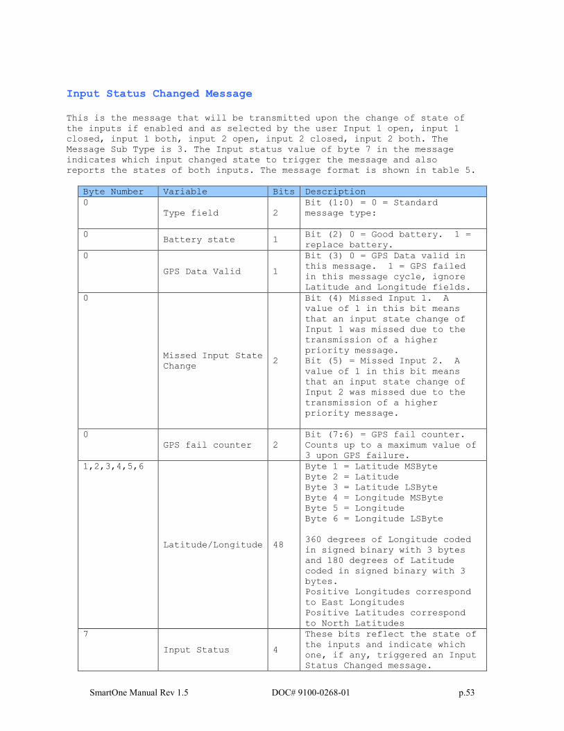
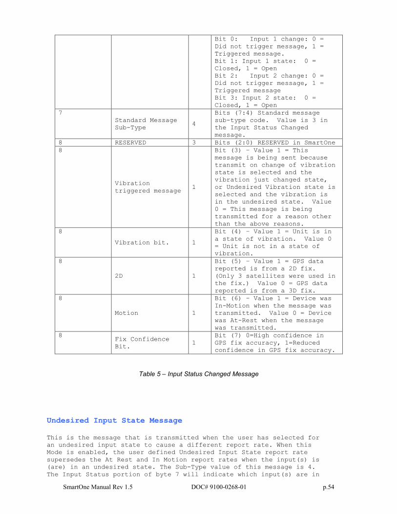
Input Status Changed Message
This is the message that will be transmitted upon the change of state of
the inputs if enabled and as selected by the user Input 1 open, input 1
closed, input 1 both, input 2 open, input 2 closed, input 2 both. The
Message Sub Type is 3. The Input status value of byte 7 in the message
indicates which input changed state to trigger the message and also
reports the states of both inputs. The message format is shown in table 5.
Byte Number Variable Bits Description
0
Type field 2
Bit (1:0) = 0 = Standard
message type:
0 Battery state 1
Bit (2) 0 = Good battery. 1 =
replace battery.
0
GPS Data Valid 1
Bit (3) 0 = GPS Data valid in
this message. 1 = GPS failed
in this message cycle, ignore
Latitude and Longitude fields.
0
Missed Input State
Change 2
Bit (4) Missed Input 1. A
value of 1 in this bit means
that an input state change of
Input 1 was missed due to the
transmission of a higher
priority message.
Bit (5) = Missed Input 2. A
value of 1 in this bit means
that an input state change of
Input 2 was missed due to the
transmission of a higher
priority message.
0
GPS fail counter 2
Bit (7:6) = GPS fail counter.
Counts up to a maximum value of
3 upon GPS failure.
1,2,3,4,5,6
Latitude/Longitude 48
Byte 1 = Latitude MSByte
Byte 2 = Latitude
Byte 3 = Latitude LSByte
Byte 4 = Longitude MSByte
Byte 5 = Longitude
Byte 6 = Longitude LSByte
360 degrees of Longitude coded
in signed binary with 3 bytes
and 180 degrees of Latitude
coded in signed binary with 3
bytes.
Positive Longitudes correspond
to East Longitudes
Positive Latitudes correspond
to North Latitudes
7
Input Status 4
These bits reflect the state of
the inputs and indicate which
one, if any, triggered an Input
Status Changed message.
SmartOne Manual Rev 1.5 DOC# 9100-0268-01 p.54
Bit 0: Input 1 change: 0 =
Did not trigger message, 1 =
Triggered message.
Bit 1: Input 1 state: 0 =
Closed, 1 = Open
Bit 2: Input 2 change: 0 =
Did not trigger message, 1 =
Triggered message
Bit 3: Input 2 state: 0 =
Closed, 1 = Open
7
Standard Message
Sub-Type 4
Bits (7:4) Standard message
sub-type code. Value is 3 in
the Input Status Changed
message.
8 RESERVED 3 Bits (2:0) RESERVED in SmartOne
8
Vibration
triggered message 1
Bit (3) – Value 1 = This
message is being sent because
transmit on change of vibration
state is selected and the
vibration just changed state,
or Undesired Vibration state is
selected and the vibration is
in the undesired state. Value
0 = This message is being
transmitted for a reason other
than the above reasons.
8
Vibration bit. 1
Bit (4) – Value 1 = Unit is in
a state of vibration. Value 0
= Unit is not in a state of
vibration.
8
2D 1
Bit (5) – Value 1 = GPS data
reported is from a 2D fix.
(Only 3 satellites were used in
the fix.) Value 0 = GPS data
reported is from a 3D fix.
8
Motion 1
Bit (6) – Value 1 = Device was
In-Motion when the message was
transmitted. Value 0 = Device
was At-Rest when the message
was transmitted.
8 Fix Confidence
Bit. 1
Bit (7) 0=High confidence in
GPS fix accuracy, 1=Reduced
confidence in GPS fix accuracy.
Table 5 – Input Status Changed Message
Undesired Input State Message
This is the message that is transmitted when the user has selected for
an undesired input state to cause a different report rate. When this
Mode is enabled, the user defined Undesired Input State report rate
supersedes the At Rest and In Motion report rates when the input(s) is
(are) in an undesired state. The Sub-Type value of this message is 4.
The Input Status portion of byte 7 will indicate which input(s) are in
SmartOne Manual Rev 1.5 DOC# 9100-0268-01 p.55
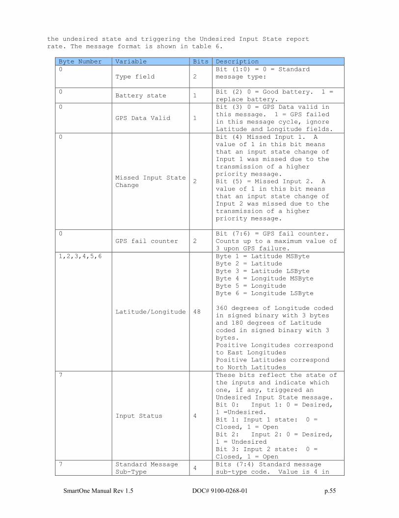
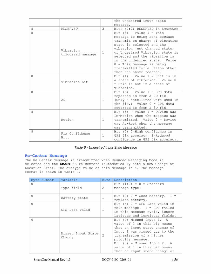
the undesired state and triggering the Undesired Input State report
rate. The message format is shown in table 6.
Byte Number Variable Bits Description
0
Type field 2
Bit (1:0) = 0 = Standard
message type:
0 Battery state 1
Bit (2) 0 = Good battery. 1 =
replace battery.
0
GPS Data Valid 1
Bit (3) 0 = GPS Data valid in
this message. 1 = GPS failed
in this message cycle, ignore
Latitude and Longitude fields.
0
Missed Input State
Change 2
Bit (4) Missed Input 1. A
value of 1 in this bit means
that an input state change of
Input 1 was missed due to the
transmission of a higher
priority message.
Bit (5) = Missed Input 2. A
value of 1 in this bit means
that an input state change of
Input 2 was missed due to the
transmission of a higher
priority message.
0
GPS fail counter 2
Bit (7:6) = GPS fail counter.
Counts up to a maximum value of
3 upon GPS failure.
1,2,3,4,5,6
Latitude/Longitude 48
Byte 1 = Latitude MSByte
Byte 2 = Latitude
Byte 3 = Latitude LSByte
Byte 4 = Longitude MSByte
Byte 5 = Longitude
Byte 6 = Longitude LSByte
360 degrees of Longitude coded
in signed binary with 3 bytes
and 180 degrees of Latitude
coded in signed binary with 3
bytes.
Positive Longitudes correspond
to East Longitudes
Positive Latitudes correspond
to North Latitudes
7
Input Status 4
These bits reflect the state of
the inputs and indicate which
one, if any, triggered an
Undesired Input State message.
Bit 0: Input 1: 0 = Desired,
1 =Undesired.
Bit 1: Input 1 state: 0 =
Closed, 1 = Open
Bit 2: Input 2: 0 = Desired,
1 = Undesired
Bit 3: Input 2 state: 0 =
Closed, 1 = Open
7 Standard Message
Sub-Type 4
Bits (7:4) Standard message
sub-type code. Value is 4 in
SmartOne Manual Rev 1.5 DOC# 9100-0268-01 p.56
the undesired input state
message.
8 RESERVED 3 Bits (2:0) RESERVED in SmartOne
8
Vibration
triggered message 1
Bit (3) – Value 1 = This
message is being sent because
transmit on change of vibration
state is selected and the
vibration just changed state,
or Undesired Vibration state is
selected and the vibration is
in the undesired state. Value
0 = This message is being
transmitted for a reason other
than the above reasons.
8
Vibration bit. 1
Bit (4) – Value 1 = Unit is in
a state of vibration. Value 0
= Unit is not in a state of
vibration.
8
2D 1
Bit (5) – Value 1 = GPS data
reported is from a 2D fix.
(Only 3 satellites were used in
the fix.) Value 0 = GPS data
reported is from a 3D fix.
8
Motion 1
Bit (6) – Value 1 = Device was
In-Motion when the message was
transmitted. Value 0 = Device
was At-Rest when the message
was transmitted.
8 Fix Confidence
Bit. 1
Bit (7) 0=High confidence in
GPS fix accuracy, 1=Reduced
confidence in GPS fix accuracy.
Table 6 - Undesired Input State Message
Re-Center Message The Re-Center message is transmitted when Reduced Messaging Mode is
selected and the SMARTONE re-centers (automatically sets a new Change of
Location Area). The subtype value of this message is 5. The message
format is shown in table 7.
Byte Number Variable Bits Description
0
Type field 2
Bit (1:0) = 0 = Standard
message type:
0 Battery state 1
Bit (2) 0 = Good battery. 1 =
replace battery.
0
GPS Data Valid 1
Bit (3) 0 = GPS Data valid in
this message. 1 = GPS failed
in this message cycle, ignore
Latitude and Longitude fields.
0
Missed Input State
Change 2
Bit (4) Missed Input 1. A
value of 1 in this bit means
that an input state change of
Input 1 was missed due to the
transmission of a higher
priority message.
Bit (5) = Missed Input 2. A
value of 1 in this bit means
that an input state change of
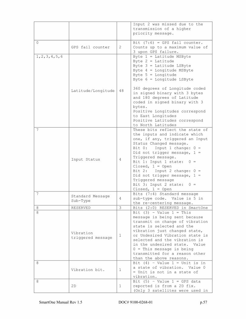
SmartOne Manual Rev 1.5 DOC# 9100-0268-01 p.57
Input 2 was missed due to the
transmission of a higher
priority message.
0
GPS fail counter 2
Bit (7:6) = GPS fail counter.
Counts up to a maximum value of
3 upon GPS failure.
1,2,3,4,5,6
Latitude/Longitude 48
Byte 1 = Latitude MSByte
Byte 2 = Latitude
Byte 3 = Latitude LSByte
Byte 4 = Longitude MSByte
Byte 5 = Longitude
Byte 6 = Longitude LSByte
360 degrees of Longitude coded
in signed binary with 3 bytes
and 180 degrees of Latitude
coded in signed binary with 3
bytes.
Positive Longitudes correspond
to East Longitudes
Positive Latitudes correspond
to North Latitudes
7
Input Status 4
These bits reflect the state of
the inputs and indicate which
one, if any, triggered an Input
Status Changed message.
Bit 0: Input 1 change: 0 =
Did not trigger message, 1 =
Triggered message.
Bit 1: Input 1 state: 0 =
Closed, 1 = Open
Bit 2: Input 2 change: 0 =
Did not trigger message, 1 =
Triggered message
Bit 3: Input 2 state: 0 =
Closed, 1 = Open
7 Standard Message
Sub-Type 4
Bits (7:4) Standard message
sub-type code. Value is 5 in
the re-centering message.
8 RESERVED 3 Bits (2:0) RESERVED in SmartOne
8
Vibration
triggered message 1
Bit (3) – Value 1 = This
message is being sent because
transmit on change of vibration
state is selected and the
vibration just changed state,
or Undesired Vibration state is
selected and the vibration is
in the undesired state. Value
0 = This message is being
transmitted for a reason other
than the above reasons.
8
Vibration bit. 1
Bit (4) – Value 1 = Unit is in
a state of vibration. Value 0
= Unit is not in a state of
vibration.
8
2D 1
Bit (5) – Value 1 = GPS data
reported is from a 2D fix.
(Only 3 satellites were used in
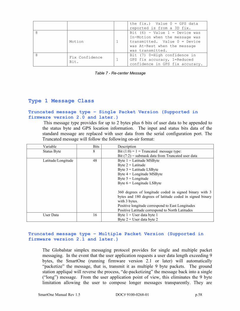
SmartOne Manual Rev 1.5 DOC# 9100-0268-01 p.58
the fix.) Value 0 = GPS data
reported is from a 3D fix.
8
Motion 1
Bit (6) – Value 1 = Device was
In-Motion when the message was
transmitted. Value 0 = Device
was At-Rest when the message
was transmitted.
8 Fix Confidence
Bit. 1
Bit (7) 0=High confidence in
GPS fix accuracy, 1=Reduced
confidence in GPS fix accuracy.
Table 7 - Re-center Message
Type 1 Message Class Truncated message type – Single Packet Version (Supported in firmware version 2.0 and later.)
This message type provides for up to 2 bytes plus 6 bits of user data to be appended to
the status byte and GPS location information. The input and status bits data of the
standard message are replaced with user data from the serial configuration port. The
Truncated message will follow the following on-air format:
Variable Bits Description
Status Byte 8 Bit (1:0) = 1 = Truncated message type:
Bit (7:2) = submask data from Truncated user data
Latitude/Longitude 48 Byte 1 = Latitude MSByte
Byte 2 = Latitude
Byte 3 = Latitude LSByte
Byte 4 = Longitude MSByte
Byte 5 = Longitude
Byte 6 = Longitude LSByte
360 degrees of longitude coded in signed binary with 3
bytes and 180 degrees of latitude coded in signed binary
with 3 bytes.
Positive longitude correspond to East Longitudes
Positive Latitude correspond to North Latitudes
User Data 16 Byte 1 = User data byte 1
Byte 2 = User data byte 2
Truncated message type – Multiple Packet Version (Supported in firmware version 2.1 and later.)
The Globalstar simplex messaging protocol provides for single and multiple packet
messaging. In the event that the user application requests a user data length exceeding 9
bytes, the SmartOne (running firmware version 2.1 or later) will automatically
“packetize” the message, that is, transmit it as multiple 9 byte packets. The ground
station appliqué will reverse the process, “de-packetizing” the message back into a single
(“long”) message. From the user application point of view, this eliminates the 9 byte
limitation allowing the user to compose longer messages transparently. They are
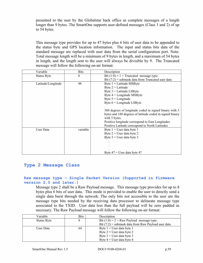
SmartOne Manual Rev 1.5 DOC# 9100-0268-01 p.59
presented to the user by the Globalstar back office as complete messages of a length
longer than 9 bytes. The SmartOne supports user-defined messages (Class 1 and 2) of up
to 54 bytes.
This message type provides for up to 47 bytes plus 6 bits of user data to be appended to
the status byte and GPS location information. The input and status bits data of the
standard message are replaced with user data from the serial configuration port. Note:
Total message length will be a minimum of 9 bytes in length, and a maximum of 54 bytes
in length, and the length sent to the user will always be divisible by 9. The Truncated
message will follow the following on-air format:
Variable Bits Description
Status Byte 8 Bit (1:0) = 1 = Truncated message type:
Bit (7:2) = submask data from Truncated user data
Latitude/Longitude 48 Byte 1 = Latitude MSByte
Byte 2 = Latitude
Byte 3 = Latitude LSByte
Byte 4 = Longitude MSByte
Byte 5 = Longitude
Byte 6 = Longitude LSByte
360 degrees of longitude coded in signed binary with 3
bytes and 180 degrees of latitude coded in signed binary
with 3 bytes.
Positive longitude correspond to East Longitudes
Positive Latitude correspond to North Latitudes
User Data variable Byte 1 = User data byte 1
Byte 2 = User data byte 2
Byte 3 = User data byte 3
.
.
.
Byte 47 = User data byte 47
Type 2 Message Class
Raw message type – Single Packet Version (Supported in firmware version 2.0 and later.)
Message type 2 shall be a Raw Payload message. This message type provides for up to 8
bytes plus 6 bits of user data. This mode is provided to enable the user to directly send a
single data burst through the network. The only bits not accessible to the user are the
message type bits needed by the receiving data processor to delineate message type
associated to the TXID. User data less than the full payload will be zero padded as
necessary. The Raw Payload message will follow the following on-air format:
Variable Bits Description
Status Byte 8 Bit (1:0) = 2 = Raw Payload message type:
Bit (7:2) = submask data from Raw Payload user data
User Data 64 Byte 1 = User data byte 1
Byte 2 = User data byte 2
Byte 3 = User data byte 3
Byte 4 = User data byte 4
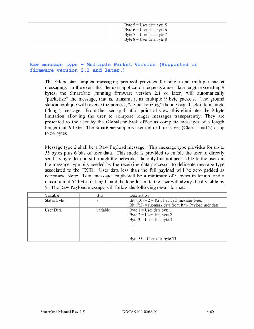
SmartOne Manual Rev 1.5 DOC# 9100-0268-01 p.60
Byte 5 = User data byte 5
Byte 6 = User data byte 6
Byte 7 = User data byte 7
Byte 8 = User data byte 8
Raw message type – Multiple Packet Version (Supported in firmware version 2.1 and later.)
The Globalstar simplex messaging protocol provides for single and multiple packet
messaging. In the event that the user application requests a user data length exceeding 9
bytes, the SmartOne (running firmware version 2.1 or later) will automatically
“packetize” the message, that is, transmit it as multiple 9 byte packets. The ground
station appliqué will reverse the process, “de-packetizing” the message back into a single
(“long”) message. From the user application point of view, this eliminates the 9 byte
limitation allowing the user to compose longer messages transparently. They are
presented to the user by the Globalstar back office as complete messages of a length
longer than 9 bytes. The SmartOne supports user-defined messages (Class 1 and 2) of up
to 54 bytes.
Message type 2 shall be a Raw Payload message. This message type provides for up to
53 bytes plus 6 bits of user data. This mode is provided to enable the user to directly
send a single data burst through the network. The only bits not accessible to the user are
the message type bits needed by the receiving data processor to delineate message type
associated to the TXID. User data less than the full payload will be zero padded as
necessary. Note: Total message length will be a minimum of 9 bytes in length, and a
maximum of 54 bytes in length, and the length sent to the user will always be divisible by
9. The Raw Payload message will follow the following on-air format:
Variable Bits Description
Status Byte 8 Bit (1:0) = 2 = Raw Payload message type:
Bit (7:2) = submask data from Raw Payload user data
User Data variable Byte 1 = User data byte 1
Byte 2 = User data byte 2
Byte 3 = User data byte 3
.
.
.
Byte 53 = User data byte 53
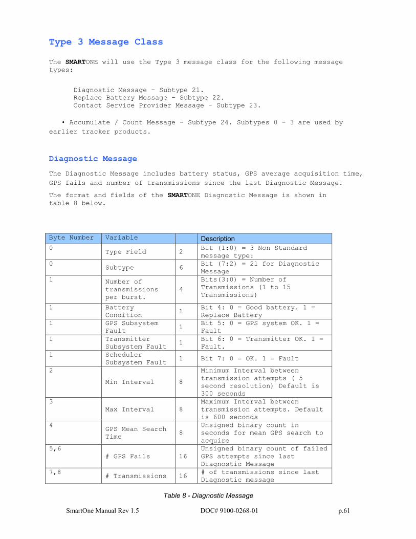
SmartOne Manual Rev 1.5 DOC# 9100-0268-01 p.61
Type 3 Message Class
The SMARTONE will use the Type 3 message class for the following message
types:
Diagnostic Message – Subtype 21.
Replace Battery Message – Subtype 22.
Contact Service Provider Message – Subtype 23.
• Accumulate / Count Message – Subtype 24. Subtypes 0 – 3 are used by
earlier tracker products.
Diagnostic Message
The Diagnostic Message includes battery status, GPS average acquisition time,
GPS fails and number of transmissions since the last Diagnostic Message.
The format and fields of the SMARTONE Diagnostic Message is shown in
table 8 below.
Byte Number Variable Description
0 Type Field 2
Bit (1:0) = 3 Non Standard
message type:
0 Subtype 6
Bit (7:2) = 21 for Diagnostic
Message
1 Number of
transmissions
per burst.
4
Bits(3:0) = Number of
Transmissions (1 to 15
Transmissions)
1 Battery
Condition 1
Bit 4: 0 = Good battery. 1 =
Replace Battery
1 GPS Subsystem
Fault 1
Bit 5: 0 = GPS system OK. 1 =
Fault
1 Transmitter
Subsystem Fault 1
Bit 6: 0 = Transmitter OK. 1 =
Fault.
1 Scheduler
Subsystem Fault 1 Bit 7: 0 = OK. 1 = Fault
2
Min Interval 8
Minimum Interval between
transmission attempts ( 5
second resolution) Default is
300 seconds
3
Max Interval 8
Maximum Interval between
transmission attempts. Default
is 600 seconds
4 GPS Mean Search
Time 8
Unsigned binary count in
seconds for mean GPS search to
acquire
5,6
# GPS Fails 16
Unsigned binary count of failed
GPS attempts since last
Diagnostic Message
7,8 # Transmissions 16
# of transmissions since last
Diagnostic message
Table 8 - Diagnostic Message
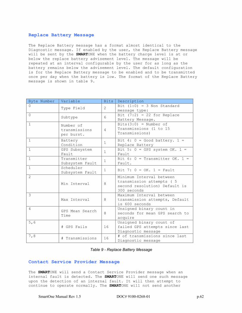
SmartOne Manual Rev 1.5 DOC# 9100-0268-01 p.62
Replace Battery Message
The Replace Battery message has a format almost identical to the
Diagnostic message. If enabled by the user, the Replace Battery message
will be sent by the SMARTONE when the battery charge level is at or
below the replace battery advisement level. The message will be
repeated at an interval configurable by the user for as long as the
battery remains below the advisement level. The default configuration
is for the Replace Battery message to be enabled and to be transmitted
once per day when the battery is low. The format of the Replace Battery
message is shown in table 9.
Byte Number Variable Bits Description
0 Type Field 2
Bit (1:0) = 3 Non Standard
message type:
0 Subtype 6
Bit (7:2) = 22 for Replace
Battery Message.
1 Number of
transmissions
per burst.
4
Bits(3:0) = Number of
Transmissions (1 to 15
Transmissions)
1 Battery
Condition 1
Bit 4: 0 = Good battery. 1 =
Replace Battery
1 GPS Subsystem
Fault 1
Bit 5: 0 = GPS system OK. 1 =
Fault
1 Transmitter
Subsystem Fault 1
Bit 6: 0 = Transmitter OK. 1 =
Fault.
1 Scheduler
Subsystem Fault 1 Bit 7: 0 = OK. 1 = Fault
2
Min Interval 8
Minimum Interval between
transmission attempts ( 5
second resolution) Default is
300 seconds
3
Max Interval 8
Maximum Interval between
transmission attempts, Default
is 600 seconds
4 GPS Mean Search
Time 8
Unsigned binary count in
seconds for mean GPS search to
acquire
5,6
# GPS Fails 16
Unsigned binary count of
failed GPS attempts since last
Diagnostic message
7,8 # Transmissions 16
# of transmissions since last
Diagnostic message
Table 9 - Replace Battery Message
Contact Service Provider Message
The SMARTONE will send a Contact Service Provider message when an
internal fault is detected. The SMARTONE will send one such message
upon the detection of an internal fault. It will then attempt to
continue to operate normally. The SMARTONE will not send another
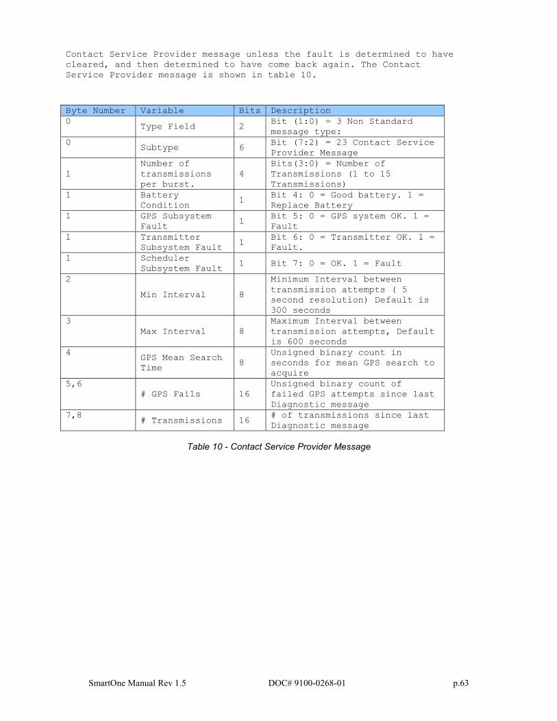
SmartOne Manual Rev 1.5 DOC# 9100-0268-01 p.63
Contact Service Provider message unless the fault is determined to have
cleared, and then determined to have come back again. The Contact
Service Provider message is shown in table 10.
Byte Number Variable Bits Description
0 Type Field 2
Bit (1:0) = 3 Non Standard
message type:
0 Subtype 6
Bit (7:2) = 23 Contact Service
Provider Message
1
Number of
transmissions
per burst.
4
Bits(3:0) = Number of
Transmissions (1 to 15
Transmissions)
1 Battery
Condition 1
Bit 4: 0 = Good battery. 1 =
Replace Battery
1 GPS Subsystem
Fault 1
Bit 5: 0 = GPS system OK. 1 =
Fault
1 Transmitter
Subsystem Fault 1
Bit 6: 0 = Transmitter OK. 1 =
Fault.
1 Scheduler
Subsystem Fault 1 Bit 7: 0 = OK. 1 = Fault
2
Min Interval 8
Minimum Interval between
transmission attempts ( 5
second resolution) Default is
300 seconds
3
Max Interval 8
Maximum Interval between
transmission attempts, Default
is 600 seconds
4 GPS Mean Search
Time 8
Unsigned binary count in
seconds for mean GPS search to
acquire
5,6
# GPS Fails 16
Unsigned binary count of
failed GPS attempts since last
Diagnostic message
7,8 # Transmissions 16
# of transmissions since last
Diagnostic message
Table 10 - Contact Service Provider Message
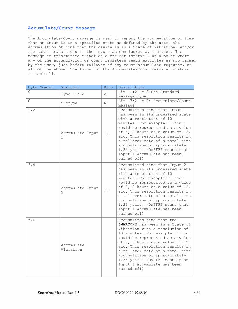
SmartOne Manual Rev 1.5 DOC# 9100-0268-01 p.64
Accumulate/Count Message
The Accumulate/Count message is used to report the accumulation of time
that an input is in a specified state as defined by the user, the
accumulation of time that the device is in a State of Vibration, and/or
the total transitions of the inputs as configured by the user. The
message is transmitted either at a pre-set interval, at a point where
any of the accumulation or count registers reach multiples as programmed
by the user, just before rollover of any count/accumulate register, or
all of the above. The format of the Accumulate/Count message is shown
in table 11.
Byte Number Variable Bits Description
0 Type Field 2
Bit (1:0) = 3 Non Standard
message type:
0 Subtype 6
Bit (7:2) = 24 Accumulate/Count
message.
1,2
Accumulate Input
1 16
Accumulated time that Input 1
has been in its undesired state
with a resolution of 10
minutes. For example: 1 hour
would be represented as a value
of 6, 2 hours as a value of 12,
etc. This resolution results in
a rollover rate of a total time
accumulation of approximately
1.25 years. (OxFFFF means that
Input 1 Accumulate has been
turned off)
3,4
Accumulate Input
2 16
Accumulated time that Input 2
has been in its undesired state
with a resolution of 10
minutes. For example: 1 hour
would be represented as a value
of 6, 2 hours as a value of 12,
etc. This resolution results in
a rollover rate of a total time
accumulation of approximately
1.25 years. (OxFFFF means that
Input 1 Accumulate has been
turned off)
5,6
Accumulate
Vibration
Accumulated time that the
SMARTONE has been in a State of
Vibration with a resolution of
10 minutes. For example: 1 hour
would be represented as a value
of 6, 2 hours as a value of 12,
etc. This resolution results in
a rollover rate of a total time
accumulation of approximately
1.25 years. (OxFFFF means that
Input 1 Accumulate has been
turned off)
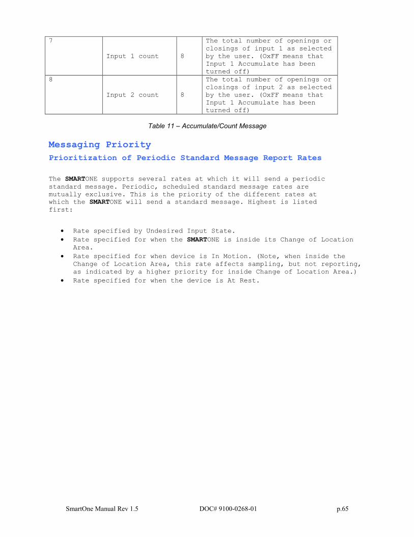
SmartOne Manual Rev 1.5 DOC# 9100-0268-01 p.65
7
Input 1 count 8
The total number of openings or
closings of input 1 as selected
by the user. (OxFF means that
Input 1 Accumulate has been
turned off)
8
Input 2 count 8
The total number of openings or
closings of input 2 as selected
by the user. (OxFF means that
Input 1 Accumulate has been
turned off)
Table 11 – Accumulate/Count Message
Messaging Priority
Prioritization of Periodic Standard Message Report Rates
The SMARTONE supports several rates at which it will send a periodic
standard message. Periodic, scheduled standard message rates are
mutually exclusive. This is the priority of the different rates at
which the SMARTONE will send a standard message. Highest is listed
first:
• Rate specified by Undesired Input State.
• Rate specified for when the SMARTONE is inside its Change of Location
Area.
• Rate specified for when device is In Motion. (Note, when inside the
Change of Location Area, this rate affects sampling, but not reporting,
as indicated by a higher priority for inside Change of Location Area.)
• Rate specified for when the device is At Rest.
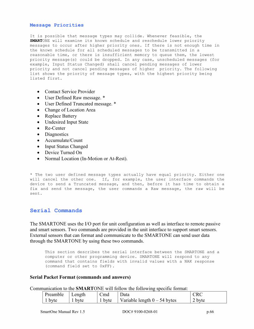
SmartOne Manual Rev 1.5 DOC# 9100-0268-01 p.66
Message Priorities
It is possible that message types may collide. Whenever feasible, the
SMARTONE will examine its known schedule and reschedule lower priority
messages to occur after higher priority ones. If there is not enough time in
the known schedule for all scheduled messages to be transmitted in a
reasonable time, or there is insufficient memory to queue them, the lowest
priority message(s) could be dropped. In any case, unscheduled messages (for
example, Input Status Changed) shall cancel pending messages of lower
priority and not cancel pending messages of higher priority. The following
list shows the priority of message types, with the highest priority being
listed first.
• Contact Service Provider
• User Defined Raw message. *
• User Defined Truncated message. *
• Change of Location Area
• Replace Battery
• Undesired Input State
• Re-Center
• Diagnostics
• Accumulate/Count
• Input Status Changed
• Device Turned On
• Normal Location (In-Motion or At-Rest).
* The two user defined message types actually have equal priority. Either one
will cancel the other one. If, for example, the user interface commands the
device to send a Truncated message, and then, before it has time to obtain a
fix and send the message, the user commands a Raw message, the raw will be
sent.
Serial Commands
The SMARTONE uses the I/O port for unit configuration as well as interface to remote passive
and smart sensors. Two commands are provided in the unit interface to support smart sensors.
External sensors that can format and communicate to the SMARTONE can send user data
through the SMARTONE by using these two commands.
This section describes the serial interface between the SMARTONE and a
computer or other programming device. SMARTONE will respond to any
command that contains fields with invalid values with a NAK response
(command field set to 0xFF).
Serial Packet Format (commands and answers)
Communication to the SMARTONE will follow the following specific format:
Preamble
1 byte
Length
1 byte
Cmd
1 byte
Data
Variable length 0 – 54 bytes
CRC
2 byte
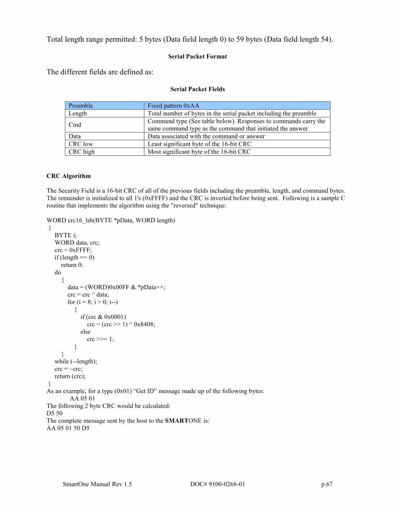
SmartOne Manual Rev 1.5 DOC# 9100-0268-01 p.67
Total length range permitted: 5 bytes (Data field length 0) to 59 bytes (Data field length 54).
Serial Packet Format
The different fields are defined as:
Serial Packet Fields
Preamble Fixed pattern 0xAA
Length Total number of bytes in the serial packet including the preamble
Cmd Command type (See table below). Responses to commands carry the
same command type as the command that initiated the answer
Data Data associated with the command or answer
CRC low Least significant byte of the 16-bit CRC
CRC high Most significant byte of the 16-bit CRC
CRC Algorithm
The Security Field is a 16-bit CRC of all of the previous fields including the preamble, length, and command bytes.
The remainder is initialized to all 1's (0xFFFF) and the CRC is inverted before being sent. Following is a sample C
routine that implements the algorithm using the "reversed" technique:
WORD crc16_lsb(BYTE *pData, WORD length)
{
BYTE i;
WORD data, crc;
crc = 0xFFFF;
if (length == 0)
return 0;
do
{
data = (WORD)0x00FF & *pData++;
crc = crc ^ data;
for (i = 8; i > 0; i--)
{
if (crc & 0x0001)
crc = (crc >> 1) ^ 0x8408;
else
crc >>= 1;
}
}
while (--length);
crc = ~crc;
return (crc);
}
As an example, for a type (0x01) “Get ID” message made up of the following bytes:
AA 05 01
The following 2 byte CRC would be calculated:
D5 50
The complete message sent by the host to the SMARTONE is:
AA 05 01 50 D5
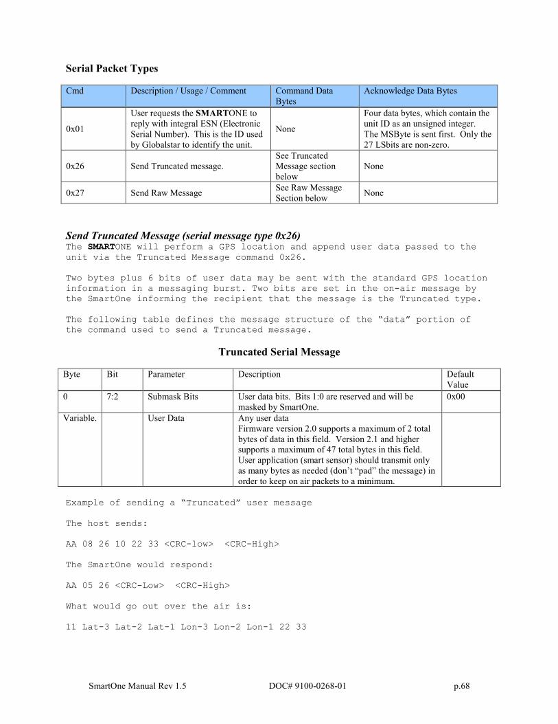
SmartOne Manual Rev 1.5 DOC# 9100-0268-01 p.68
Serial Packet Types
Cmd Description / Usage / Comment Command Data
Bytes
Acknowledge Data Bytes
0x01
User requests the SMARTONE to
reply with integral ESN (Electronic
Serial Number). This is the ID used
by Globalstar to identify the unit.
None
Four data bytes, which contain the
unit ID as an unsigned integer.
The MSByte is sent first. Only the
27 LSbits are non-zero.
0x26 Send Truncated message.
See Truncated
Message section
below
None
0x27 Send Raw Message See Raw Message
Section below None
Send Truncated Message (serial message type 0x26) The SMARTONE will perform a GPS location and append user data passed to the
unit via the Truncated Message command 0x26.
Two bytes plus 6 bits of user data may be sent with the standard GPS location
information in a messaging burst. Two bits are set in the on-air message by
the SmartOne informing the recipient that the message is the Truncated type.
The following table defines the message structure of the “data” portion of
the command used to send a Truncated message.
Truncated Serial Message
Byte Bit Parameter Description Default
Value
0 7:2 Submask Bits User data bits. Bits 1:0 are reserved and will be
masked by SmartOne.
0x00
Variable. User Data Any user data
Firmware version 2.0 supports a maximum of 2 total
bytes of data in this field. Version 2.1 and higher
supports a maximum of 47 total bytes in this field.
User application (smart sensor) should transmit only
as many bytes as needed (don’t “pad” the message) in
order to keep on air packets to a minimum.
Example of sending a “Truncated” user message
The host sends:
AA 08 26 10 22 33 <CRC-low> <CRC-High>
The SmartOne would respond:
AA 05 26 <CRC-Low> <CRC-High>
What would go out over the air is:
11 Lat-3 Lat-2 Lat-1 Lon-3 Lon-2 Lon-1 22 33
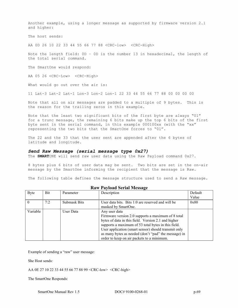
SmartOne Manual Rev 1.5 DOC# 9100-0268-01 p.69
Another example, using a longer message as supported by firmware version 2.1
and higher:
The host sends:
AA 0D 26 10 22 33 44 55 66 77 88 <CRC-low> <CRC-High>
Note the length field: 0D – 0D is the number 13 in hexadecimal, the length of
the total serial command.
The SmartOne would respond:
AA 05 26 <CRC-Low> <CRC-High>
What would go out over the air is:
11 Lat-3 Lat-2 Lat-1 Lon-3 Lon-2 Lon-1 22 33 44 55 66 77 88 00 00 00 00
Note that all on air messages are padded to a multiple of 9 bytes. This is
the reason for the trailing zeros in this example.
Note that the least two significant bits of the first byte are always “01”
for a trunc message, the remaining 6 bits make up the top 6 bits of the first
byte sent in the serial command, in this example 000100xx (with the “xx”
representing the two bits that the SmartOne forces to “01”.
The 22 and the 33 that the user sent are appended after the 6 bytes of
latitude and longitude.
Send Raw Message (serial message type 0x27) The SMARTONE will send raw user data using the Raw Payload command 0x27.
8 bytes plus 6 bits of user data may be sent. Two bits are set in the on-air
message by the SmartOne informing the recipient that the message is Raw.
The following table defines the message structure used to send a Raw message.
Raw Payload Serial Message Byte Bit Parameter Description Default
Value
0 7:2 Submask Bits User data bits. Bits 1:0 are reserved and will be
masked by SmartOne.
0x00
Variable User Data Any user data
Firmware version 2.0 supports a maximum of 8 total
bytes of data in this field. Version 2.1 and higher
supports a maximum of 53 total bytes in this field.
User application (smart sensor) should transmit only
as many bytes as needed (don’t “pad” the message) in
order to keep on air packets to a minimum.
Example of sending a “raw” user message:
She Host sends:
AA 0E 27 10 22 33 44 55 66 77 88 99 <CRC-low> <CRC-high>
The SmartOne Responds:
SmartOne Manual Rev 1.5 DOC# 9100-0268-01 p.70
AA 05 27 <CRC-low> <CRC-high>
What actually goes out over the air is:
12 22 33 44 55 66 77 88 99
Another example, using a longer message as supported by firmware version 2.1 and higher:
The Host sends:
AA 21 27 10 22 33 44 55 66 77 88 99 AA BB CC DD EE FF 11 22 33 44 55 66 77 88 99 AA 44 56 78 <CRC-low>
<CRC-high>
Note the length field, the command contains a total of 33 bytes. The length is 21 Hexadecimal, which is equal to 33
decimal.
The SmartOne Responds:
AA 05 27 <CRC-low> <CRC-high>
What actually goes out over the air is:
12 22 33 44 55 66 77 88 99 AA BB CC DD EE FF 11 22 33 44 55 66 77 88 99 AA 44 56 78 00 00 00 00 00 00 00
00
Note that all on air messages are padded to a multiple of 9 bytes. This is the reason for the trailing zeros in this
example.
Note that the least two significant bits of the first byte are always “10” for a raw message (a HEX or decimal value
of “2”, the remaining 6 bits make up the top 6 bits of the first byte sent in the serial command, in this example
000100xx (with the “xx” representing the two bits that the SmartOne forces to “10”.
A simple ACK or NAK from the SMARTONE Device to the host (smart sensor):
ACKs:
AA 05 26 <crc crc> (for the Truncated message)
AA 05 27 <crc crc> (for the Raw message)
NAK:
AA 05 FF <crc crc> (NAK).
Notes:
As the SmartOne operates, some debugging traces come out of the serial port. Those traces should simply be
ignored. Once the handshake line is pulled low, the unit is in “command mode” and debugging traces will stop.
User commands will ALWAYS be responded to immediately with either an acknowledgement or a NAK (as shown
in the examples above). Once an acknowledgement (or NAK) is received, the host should simply ignore the serial
port until the next time it sends a command.
The most common reasons for a NAK are incorrect CRC, incorrect length field, or incorrect command field (i.e. not
0x26 or 0x27 for trunc and raw respectively).
The handshake line should be pulled low before sending each serial message. The recommended use of the
handshake line is:
SmartOne Manual Rev 1.5 DOC# 9100-0268-01 p.71
Pull handshake low.
Wait 2 – 3 milliseconds.
Send command
Receive response.
Raise handshake high.
Connecting Serial Devices to the SMARTONE
The SMARTONE accepts a serial connection at 3 volt levels (Max), at 9600
baud. The relevant pins are TX, RX, Handshake and ground. The SMARTONE can
connect with devices that contain an asynchronous UART at 3 volt levels.
(High State: 2.7-3 Volts, Low State: 0 Volts. Please contact Globalstar Support for more information.
CAUTION: NEVER attempt to connect the SMARTONE directly to the pins on a
computer's RS232 port. The voltages in RS232 are too high and can damage the
SMARTONE.
Any deviations from the above guidelines will violate all RMA requirements
and prevent any no-cost replacement. See Appendix K for information on the Serial Input Cable for the SMARTONE
SmartOne Manual Rev 1.5 DOC# 9100-0268-01 p.72
Glossary of Terms
Accumulate Hours – The activity time accumulated in the Inputs of the
device while the Input is in the user defined state.
Activation – The activation of an ESN (electronic serial number) on the
Globalstar satellite network. The process consists of programming a
start and an end date for the use of the ESN and the payment of certain
fees to Globalstar. Sometimes referred to as “provisioning.”
At Rest – a tracker is considered to be at rest when the comparison of a
new GPS reading to a previous GPS reading indicates that the tracker has
not changed location by more than a specified minimum distance. The
specified minimum time and the specified minimum distance are both
configuration parameters.
C
Configuration – the collection of variables that control the operating
performance of a tracker. Sometimes referred to as the “configuration.”
Configure (configuring) – Programming (setting) the variables that
control the operation performance of a tracker.
Count Events – The accumulated number of state changes in the Inputs of
the device.
D
Delay To Start – Specific delay in time following the programming of the
device to commence operation.
Desired State – The state of the Input in normal condition defined by
the user.
E
ESN – Electronic Serial Number is a unique number assigned to each
SMARTONE device. The ESN is used by the Globalstar Simplex Network to
identify messages from the devices o the field.
F
Failed GPS reading – A GPS reading could not be processed from available
GPS satellite signals.
FW Ver – Firmware version is the existing software loaded in the device
main processor
G
GPS – The GPS (Global Positioning System) is a "constellation" of 24
well-spaced satellites that orbit the Earth and make it possible for
SmartOne Manual Rev 1.5 DOC# 9100-0268-01 p.73
people with ground receivers to pinpoint their geographic location.
GPS reading – The longitude, latitude, time, and date information
obtained from processing the signals from the GPS satellites.
I
In Motion – The unit is considered to be In Motion when there is a State
of Vibration – and – when a comparison of a new GPS reading to a
previous GPS reading indicates the tracker has changed location by at
least a specified minimum distance. The specified minimum time and the
specified minimum distance are both configuration parameters.
Inaccurate GPS reading – The longitude and latitude information obtained
from processing the signals from the GPS satellites when a tracker can
not observe an adequate number of satellites; the GPS signals were
jammed by electronic interference; the GPS signals were reflected from
objects creating multi-path conditions; or weather conditions distorted
the GPS signals. An inaccurate GPS reading may have longitude and
latitude errors of a mile or more.
Input – A digital channel in the device that allows the detection of
switch stage changes. The inputs are dry contact inputs, ON/OFF.
Level of Sensitivity for Vibration Sensor – a configurable parameter
that sets the number of pulses per minute that a vibration sensor must
detect to be considered sensing vibration.
M
Message – A collection of information that is transmitted in a group
over the satellite network.
Message Interval – The amount of time specified by the user between
Location Messages. The SMARTONE transmits a Location Message once the
Message Interval has elapsed. The internal clock on the device is reset
to the interval time after each transmission. The SMARTONE is in low
power consumption Mode during the interval to preserve battery life.
Message Time(s) of Day – The specific time of day in military format for
the SMARTONE to transmit Location Messages. . The SMARTONE is in low
power consumption Mode between the specific times of day to preserve
battery life.
Message Transmission – The process of sending a message over the
satellite network. The process includes sending a message multiple
times to improve the transmission success rate.
N
Number of message repeats – The number of times a message is send in a
message transmission with the same UMN. The number of message repeats
SmartOne Manual Rev 1.5 DOC# 9100-0268-01 p.74
is configurable during the tracker set up process. Globalstar only
counts repeated messages as one message if it is received three times or
less. If the same message is receive more than three times Globalstar
may count the message as more than one message for billing purposes
S
Self Test – An internal unit test that is performed by the processor.
The test checks for proper operation of functions that can be tested by
the processor.
State of lacking Vibration – The vibration sensor is indicating a cease
of vibration when the number of vibration pulses per minute is lower
than the Level of Sensitivity for Vibration Sensor number for the time
required to determine if a State of Vibration has ceased.
State of Vibration – The vibration sensor is in a State of Vibration
when the number of vibration pulses per minute exceeds the Level of
Sensitivity for Vibration Sensor for the time required to detect a State
of Vibration.
T
Time to be in a State of Lacking Vibration– a configurable parameter
that sets the period of time vibration has to be absent to determine if
a State of Vibration has ceased.
Time to be in a State of Vibration – a configurable parameter that sets
the period of time used to determine if a State of Vibration exists.
U
Undesired State Message – The SMARTONE sends this message at a user
defined interval while any of its Inputs are in the closed or opened
state depending on the user selection
SmartOne Manual Rev 1.5 DOC# 9100-0268-01 p.75
Appendix A: Technical Support
For technical support please contact Globalstar, Inc. corporate headquarters
at: 1.877.452.5782 or 1.905.712.7197 or by email: [email protected].
SmartOne Manual Rev 1.5 DOC# 9100-0268-01 p.76
Appendix B: RF Radiation Exposure Statement
This equipment complies with FCC radiation exposure limits set forth for
an uncontrolled environment. End users must follow the specific
operating instructions for satisfying RF exposure compliance. The
antenna(s) used for this transmitter must be installed to provide a
separation distance of at least 20 cm from all persons and must not be
co-located or operating in conjunction with any other antenna or
transmitter.
RAPPORT D'EXPOSITION DE RAYONNEMENT DE LA FCC RF Cet equipment est conforme aux limites
d'exposition de rayonnement de la FCC RF determinees pour un environnement non controle. Cet equipment devrait
etre installe et actionne avec une distance minimum de 20 cm entre le radiature et votre corps.
SmartOne Manual Rev 1.5 DOC# 9100-0268-01 p.77
Appendix C: Regulatory Notices
FCC/IC Notices
This equipment has been tested and found to comply with the limits for a
Class B digital device, pursuant to Part 15 of the FCC Rules. Operation is
subject to the following two conditions: (1) This device may not cause
harmful interference, and (2) this device must accept any interference
received, including interference that may cause undesired operation. This
device complies with the requirements for radio astronomy site avoidance as
specified by the Globalstar National Science Foundation agreement of 2001. It
is compliant with CFR 25.213.
This Class B digital apparatus complies with Canadian ICES-003.
This device automatically adjusts its transmission frequency according to its
location and is compliant with international regulatory requirements.
Changes or modifications not expressly approved by the party responsible
for compliance could void the user’s authority to operate the
equipment.
NOTE: The manufacturer is not responsible for any radio or TV
interference caused by unauthorized modifications to this equipment.
Such modifications could void the user’s authority to operate the
equipment.
The device and technology herein is protected under U.S. Patent numbers
6,317,029; 6,396,819; 7,337,061; 7,672,639 & patents pending.
Battery Caution Statement per IEC/EN60960-1 1.7.13 Caution! Risk
of explosion if battery is replaced by an incorrect type.
Dispose of used batteries according to the instructions.
SmartOne Manual Rev 1.5 DOC# 9100-0268-01 p.78
FCC/IC Notice Cet équipement a été examiné et s’est avéré conforme aux limites pour un dispositif numérique de la classe B, conformément à la partie 15 des règles de FCC. L'opération est sujette aux deux conditions suivantes : (1) ce dispositif ne doit pas causer d'interférence nocive, et (2) ce dispositif doit accepter n'importe quelle interférence reçue, y compris l'interférence qui peut causer une opération peu désirée. Ce dispositif est conforme aux conditions d’éviter les sites d'emplacement de radio-astronomie comme spécifique par l'accord Foundation National des Sciences de Globalstar de 2001. Il est conforme avec CFR 25.213. Ce dispositif s'ajuste automatiquement sur la fréquence de transmission selon son endroit et est conforme avec des conditions de normalisation internationales. Cet appareillage numérique de la classe B est conforme à ICES-003 d’Industrie Canada. ATTENTIONS ET AVERTISSEMENTS Tous les changements ou modifications pas expressément approuvés par la garantie de ce dispositif peuvent empêcher ou annuler l’utilisateur d’opérer cet équipement. Danger d'explosion si la batterie est inexactement remplacée. Remplacez seulement par la même batterie ou le type équivalent recommandé. Débarrassez-vous des batteries utilisées selon les instructions du fabricant.
SmartOne Manual Rev 1.5 DOC# 9100-0268-01 p.79
Appendix D: Environmental Specifications
• -30 degrees C to +60 degrees C operating temperature range. The
device shall remain operational over the -40 to +80 degrees C range
though may experience battery life and RF signal degradation.
• IP67 (Intrusion Protection)
• IP68 (Freeze-Thaw)
• IP69K (High Pressure Washing)
• MIL-STD-810F (95% to 100% Condensing) (Humidity)
• MIL-STD 810E Method 509.3 5% NaCl, 95% Distilled Water (Salt Fog)
• SAE J1455 (Random 20 Hz to 2000 Hz, 0.40 g2/hz, One Hour Per Axis)
(Vibration)
• SAE J1455 (Thermal Shock Test)
• SAE J1455 (Thermal Shock Test Performed Under 2 Inches Of Water)
• Intrinsically Safe to Class 1, Division 1, Group A-D Standards. Only
used batteries- not when used with line power.(United States UL913 &
Canada CSA C22.2 No. 157)
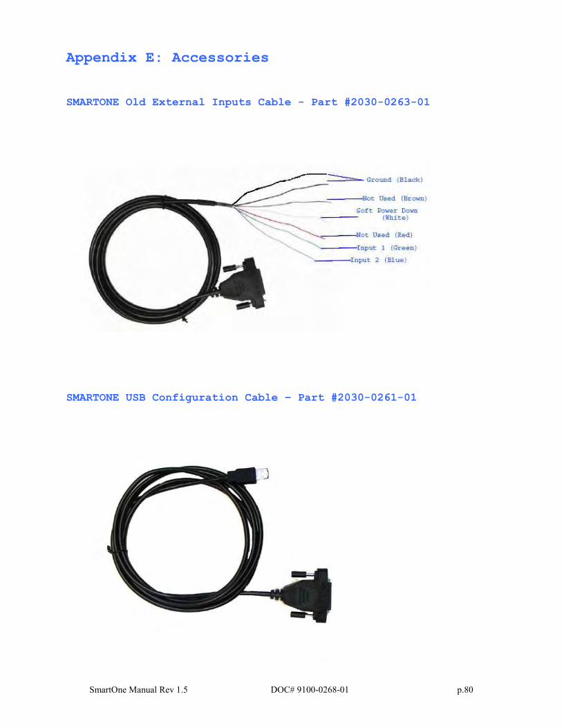
SmartOne Manual Rev 1.5 DOC# 9100-0268-01 p.80
Appendix E: Accessories
SMARTONE Old External Inputs Cable - Part #2030-0263-01
SMARTONE USB Configuration Cable – Part #2030-0261-01
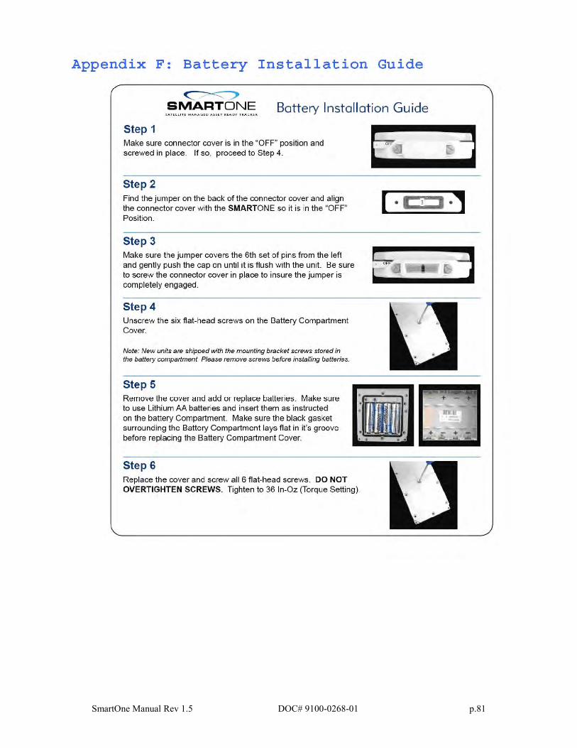
SmartOne Manual Rev 1.5 DOC# 9100-0268-01 p.81
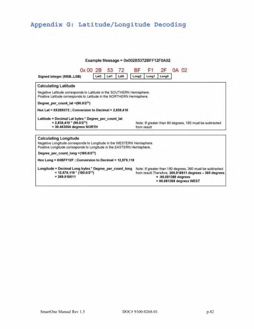
SmartOne Manual Rev 1.5 DOC# 9100-0268-01 p.82
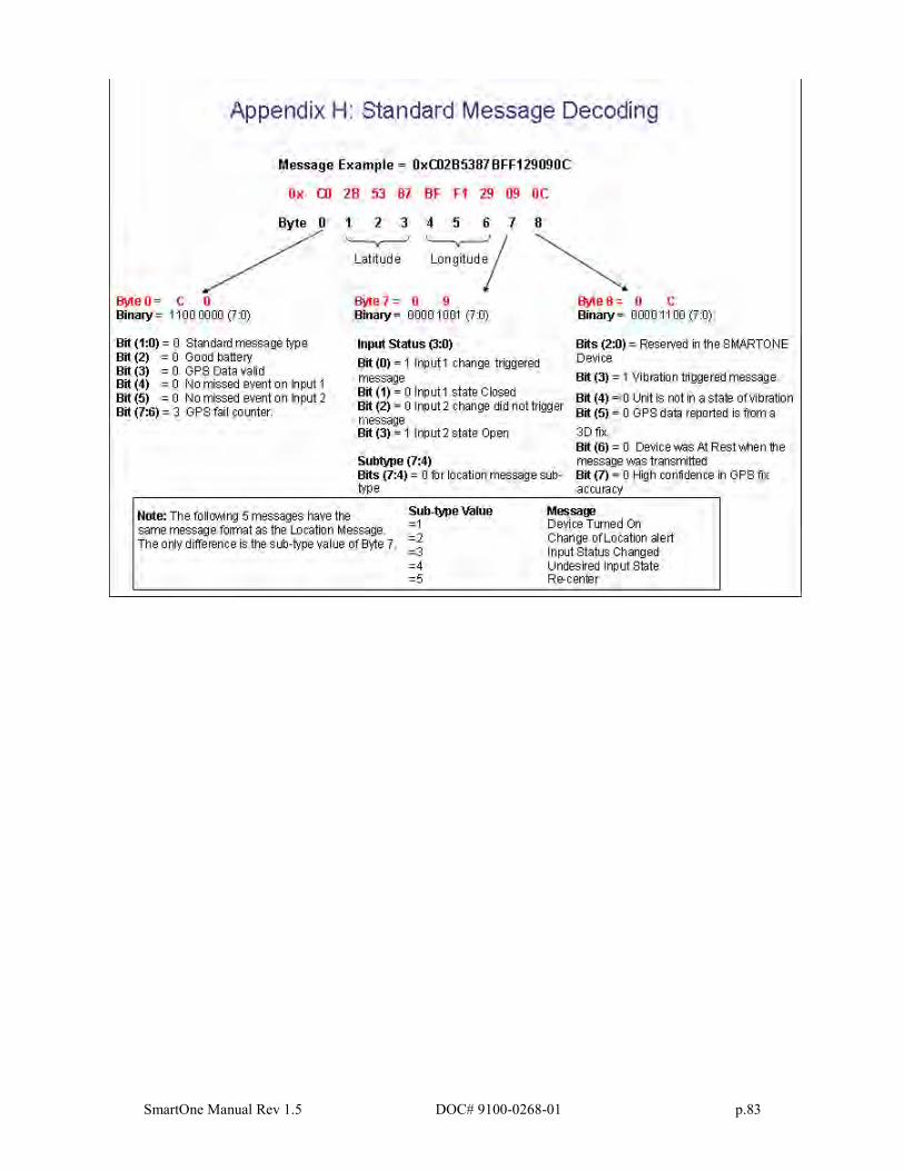
SmartOne Manual Rev 1.5 DOC# 9100-0268-01 p.83
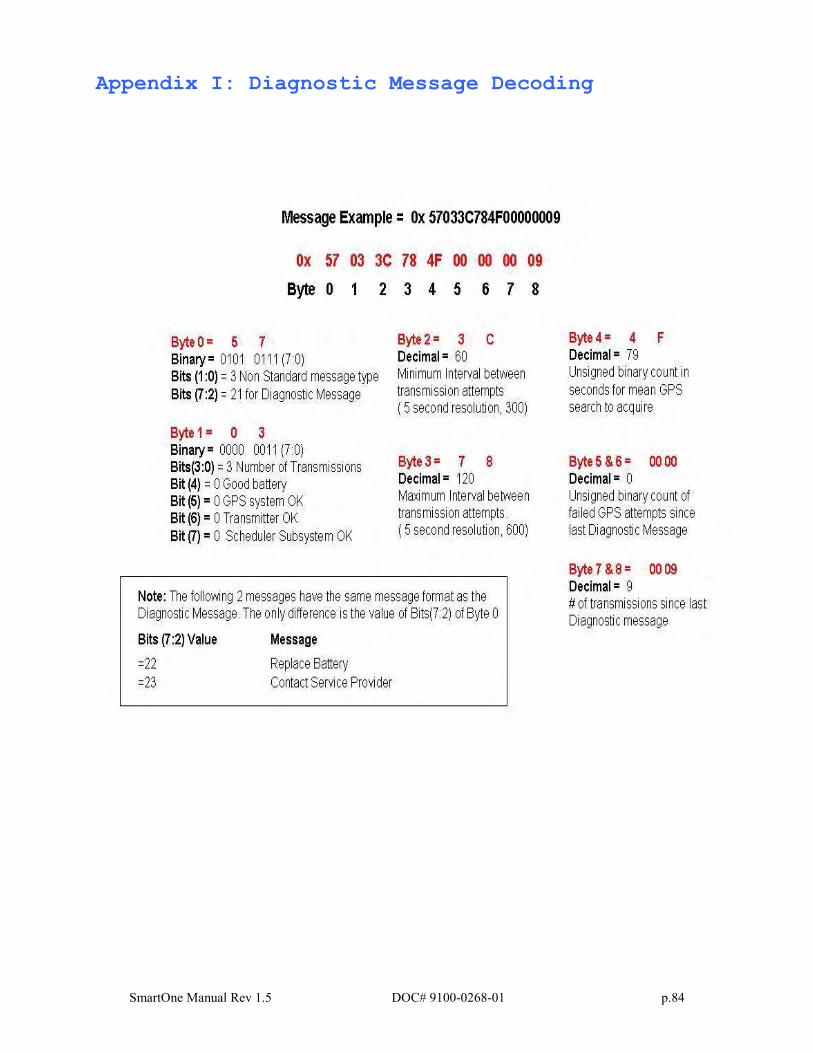
SmartOne Manual Rev 1.5 DOC# 9100-0268-01 p.84
Appendix I: Diagnostic Message Decoding
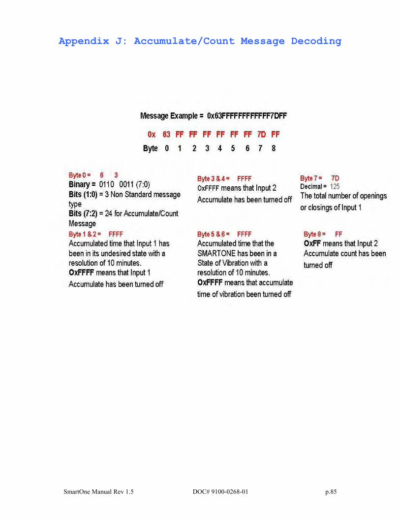
SmartOne Manual Rev 1.5 DOC# 9100-0268-01 p.85
Appendix J: Accumulate/Count Message Decoding
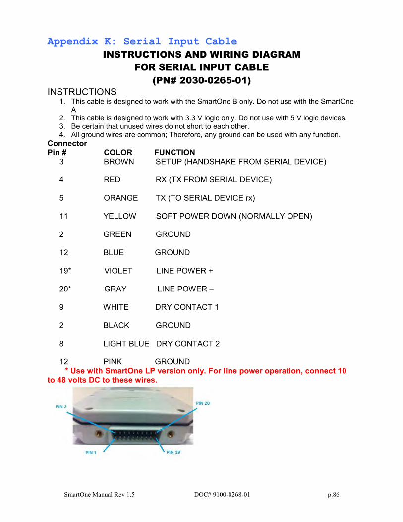
SmartOne Manual Rev 1.5 DOC# 9100-0268-01 p.86
Appendix K: Serial Input Cable
INSTRUCTIONS AND WIRING DIAGRAM
FOR SERIAL INPUT CABLE
(PN# 2030-0265-01)
INSTRUCTIONS 1. This cable is designed to work with the SmartOne B only. Do not use with the SmartOne
A 2. This cable is designed to work with 3.3 V logic only. Do not use with 5 V logic devices. 3. Be certain that unused wires do not short to each other. 4. All ground wires are common; Therefore, any ground can be used with any function.
Connector Pin # COLOR FUNCTION
3 BROWN SETUP (HANDSHAKE FROM SERIAL DEVICE) 4 RED RX (TX FROM SERIAL DEVICE) 5 ORANGE TX (TO SERIAL DEVICE rx) 11 YELLOW SOFT POWER DOWN (NORMALLY OPEN)
2 GREEN GROUND
12 BLUE GROUND
19* VIOLET LINE POWER +
20* GRAY LINE POWER –
9 WHITE DRY CONTACT 1
2 BLACK GROUND
8 LIGHT BLUE DRY CONTACT 2
12 PINK GROUND
* Use with SmartOne LP version only. For line power operation, connect 10 to 48 volts DC to these wires.
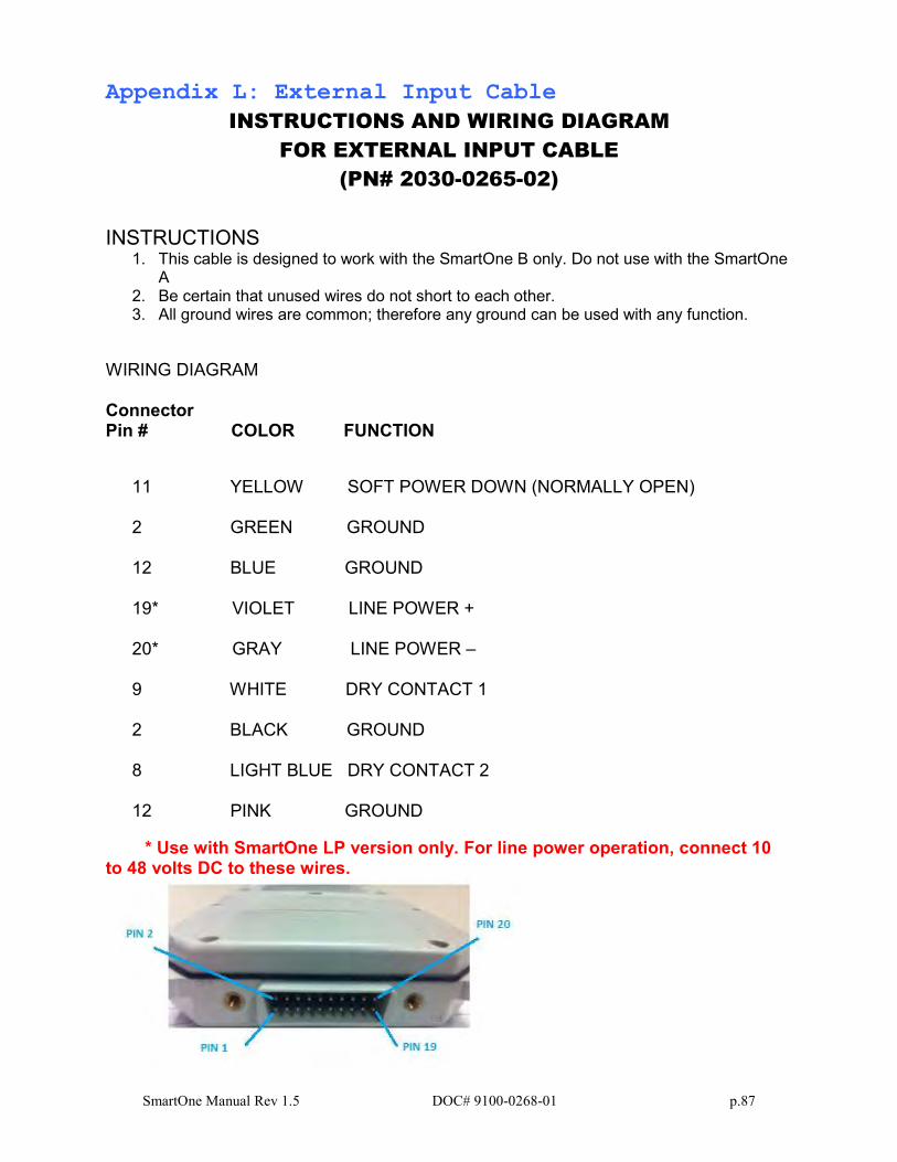
SmartOne Manual Rev 1.5 DOC# 9100-0268-01 p.87
Appendix L: External Input Cable
INSTRUCTIONS AND WIRING DIAGRAM
FOR EXTERNAL INPUT CABLE
(PN# 2030-0265-02)
INSTRUCTIONS
1. This cable is designed to work with the SmartOne B only. Do not use with the SmartOne A
2. Be certain that unused wires do not short to each other. 3. All ground wires are common; therefore any ground can be used with any function.
WIRING DIAGRAM Connector Pin # COLOR FUNCTION
11 YELLOW SOFT POWER DOWN (NORMALLY OPEN)
2 GREEN GROUND
12 BLUE GROUND
19* VIOLET LINE POWER +
20* GRAY LINE POWER –
9 WHITE DRY CONTACT 1
2 BLACK GROUND
8 LIGHT BLUE DRY CONTACT 2
12 PINK GROUND
* Use with SmartOne LP version only. For line power operation, connect 10 to 48 volts DC to these wires.