sm0758 f-t01-as and df-t01-as 122214 - syntronmh.comsyntronmh.com/documents/pdf/sm0758_f-t01-as and...
TRANSCRIPT
Service Instructions Syntron® Electromagnetic Vibrating Feeders Model: F-T01-AS
DF-T01-AS
1
Service Instructions
Syntron Light-Capacity Electromagnetic Vibrating Feeders Models: F-T01-AS and DF-T01-AS Contents Page Introduction .............................................. 1 Theory of Operation ................................. 2 Long Term Storage .................................. 3 Installation ............................................... 3 Operation ................................................. 4 Maintenance ............................................ 4 Trouble Shooting ..................................... 5 Spring Replacement ................................ 6 Air Gap .................................................... 6 Checking Feeder Current ......................... 7 Stroke Gauge .......................................... 7 Illustration ................................................ 7 Operating Specifications .......................... 7 Parts List.................................................. 8
Syntron Material Handling, LLC. reserves the right to make changes at any time, without notice and without any liability or other obligation on its part, in material, equipment, specifications and model. Syntron Material Handling also reserves the right to discontinue the manufacture and sale of models, and the parts and components thereof.
Safety Instructions: Product safety labels must remain highly visible on the equipment. Should safety labels require replacement contact Syntron Material Handling for an additional supply free of charge.
The instructions and data herein are vital to the proper installation and operation of this equipment. In order to avoid delays due to faulty installation or operation, please see that these instructions are read by the persons who will install, operate and maintain this equipment. Supporting information, such as drawings, may be attached to this manual. The information contained therein take precedence over corresponding information printed in this manual.
INTRODUCTION
The Syntron F/DF-T01-AS Feeder assembly is an electromagnetic unit, consisting of a dynamically balanced, two-mass vibrating system. This system consists of a trough and trough connecting bracket coupled to an electromagnetic drive by means of leaf springs. NOTE: When supplied without a trough assembly, the drive unit can be used with chutes, tracks, etc. (supplied by the customer). The drive (a coil and core assembly) is located within the base housing and is connected directly to the rear of drive unit housing. An armature assembly, also included as part of the drive unit, is located opposite the core and coil and is connected directly to the trough connecting bracket. The springs are clamped at the bottom to the drive unit housing, at the top to the trough connecting bracket. The trough, trough
2
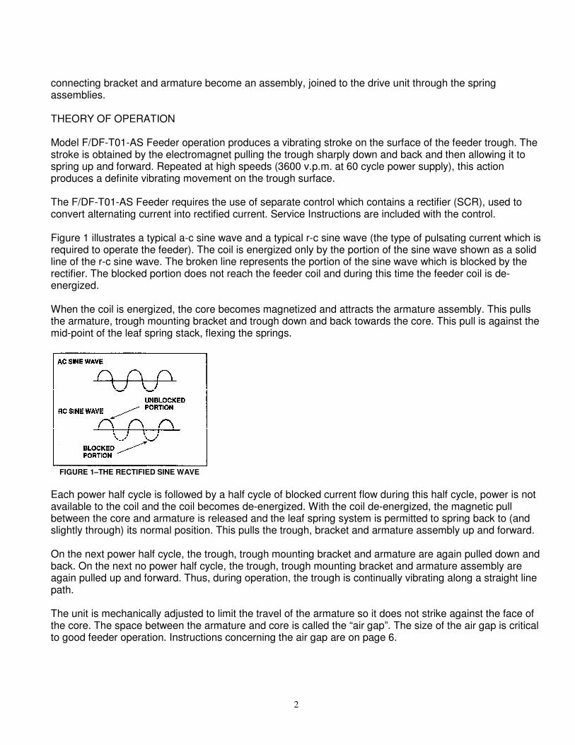
connecting bracket and armature become an assembly, joined to the drive unit through the spring assemblies. THEORY OF OPERATION Model F/DF-T01-AS Feeder operation produces a vibrating stroke on the surface of the feeder trough. The stroke is obtained by the electromagnet pulling the trough sharply down and back and then allowing it to spring up and forward. Repeated at high speeds (3600 v.p.m. at 60 cycle power supply), this action produces a definite vibrating movement on the trough surface. The F/DF-T01-AS Feeder requires the use of separate control which contains a rectifier (SCR), used to convert alternating current into rectified current. Service Instructions are included with the control. Figure 1 illustrates a typical a-c sine wave and a typical r-c sine wave (the type of pulsating current which is required to operate the feeder). The coil is energized only by the portion of the sine wave shown as a solid line of the r-c sine wave. The broken line represents the portion of the sine wave which is blocked by the rectifier. The blocked portion does not reach the feeder coil and during this time the feeder coil is de-energized. When the coil is energized, the core becomes magnetized and attracts the armature assembly. This pulls the armature, trough mounting bracket and trough down and back towards the core. This pull is against the mid-point of the leaf spring stack, flexing the springs.
FIGURE 1–THE RECTIFIED SINE WAVE
Each power half cycle is followed by a half cycle of blocked current flow during this half cycle, power is not available to the coil and the coil becomes de-energized. With the coil de-energized, the magnetic pull between the core and armature is released and the leaf spring system is permitted to spring back to (and slightly through) its normal position. This pulls the trough, bracket and armature assembly up and forward. On the next power half cycle, the trough, trough mounting bracket and armature are again pulled down and back. On the next no power half cycle, the trough, trough mounting bracket and armature assembly are again pulled up and forward. Thus, during operation, the trough is continually vibrating along a straight line path. The unit is mechanically adjusted to limit the travel of the armature so it does not strike against the face of the core. The space between the armature and core is called the “air gap”. The size of the air gap is critical to good feeder operation. Instructions concerning the air gap are on page 6.
3
LONG TERM STORAGE When received, the equipment should be carefully unpacked. Give the equipment a thorough visual inspection to reveal any damage that may occurred during shipment. If damage is found, contact Syntron Material Handling, Material Handling Solutions and the shipping carrier at once.
If the feeder is placed in storage, prior to installation, store the feeder in the shipping carton.
CAUTION: Do not support the weight of the unit by the trough assembly. This will distort and damage the springs.
When storing the controller, plug all openings in the control box to prevent dirt, rodents and insects from entering. Syntron Material Handling advises placing a corrosion preventive inside control box. Cover the controller and place it in an area protected from extreme heat. Do not drop controller. The force of the impact may damage the components.
INSTALLATION
CAUTION: Do not lift the unit by the trough.
The feeder has been factory tuned for your specific application. Handling by the trough could cause damage to the feeder.
When received the feeder and controller should be carefully unpacked. All packing bands, paper, etc., must be removed. Check the controller components for protective shipping blocks, tape etc.
Inspect all the equipment received and report any damage which may have occurred during shipment. If damage is found, notify Syntron Material Handling, Material Handling Solutions and the shipping carrier at once.
When installing the feeder, consideration must be given to the area of support. Model F/DF-T01-AS feeders can weigh over 33 pounds (15 kg) and a support must be selected that will safely carry the full weight of the unit under loaded operating conditions.
CAUTION: The feeder must not come in contact with any rigid object or adjacent surface that could hamper its vibrating action.
A ½” (12.7 mm) clearance must be maintained. Any connections (such as dust seals) between the trough and adjacent objects must be flexible, preferably cloth or rubber.
The separate control assembly should be installed as close to the feeder as possible. Installation on a wall in a clean dry location, free from excessive vibration is recommended.
WARNING: The electrical power supply connection to the Syntron Material Handling supplied controller must be made through a customer supplied safety disconnect switch. This switch must be mounted next to the controller.
If possible, install the controller at a location where it will receive adequate ventilation. This will insure prolonged component life.
CAUTION: The conductor between the feeder and controller must be of a size sufficient to carry the current and voltage as stamped on the equipment nameplate. WARNING: Be certain the equipment is properly grounded.
4
OPERATION
CAUTION: Unauthorized modification of the feeder or use of unauthorized replacement parts may damage the feeder.
Syntron Material Handling will not assume responsibility for feeder performance as a result of any unauthorized alterations to the equipment. Consult Syntron Material Handling, Material Handling Solutions before modifying your feeder.
With the feeder and controller properly installed and all wiring completed, the equipment is ready for operation.
WARNING: While in operation the controller must be kept closed and secured.
Before starting the equipment, check all external bolts on the feeder assembly for tightness. Then, rotate the control knob on the controller to a low counterclockwise position. Turn the switch to its “on” position and the feeder will begin operating at a low rate of feed. Check the method of feeder support, making sure it is substantial and the feeder is not touching any rigid objects or an adjacent structure.
CAUTION: When operating normally, the feeder should perform with a smooth even stroke. If a loud “striking” noise occurs, immediately turn off feeder.
Striking is the result of the faces of the core and armature making contact. Striking can result in serious damage to the unit! Refer to the Air Gap section of these instructions for corrective action.
With the feeder operating satisfactorily, load the trough with the material to be conveyed and adjust the control knob to the desired output. Clockwise rotation will increase the feed rate; counterclockwise will decrease the feed rate. The material will flow along the trough surface in a smooth controlled rate of feed toward the discharge.
MAINTENANCE WARNING: Before performing any maintenance work, the electrical power supply must be disconnected at the safety disconnect switch and locked out.
Some materials, due to their nature, adhere to the trough surfaces. These deposits increase dead weight to the feeder trough, and if permitted to build up excessively, will alter the natural frequency (tuning) of the feeder. Material build-up on the trough should be removed as a daily practice. Look for material build-up at the rear of the feeder trough, particularly around and under hopper openings.
A clean, dry compressed air supply is recommended for general cleaning of these units. Water is not recommended.
CAUTION: Never oil the spring assembly. This destroys the clamping effect of the spring pads against one another.
In the event repairs are necessary, take immediate action to avoid possible injury to personnel and damage to the feeder parts from faulty operation. When ordering replacement parts, include all information given on the nameplate.
5
CAUTION: Any signs of excessive heat or burned components are an indication of trouble. At first notice of an overheating condition, immediately investigate and correct the cause.
Feeder coils, under normal operating conditions, run warm but never too hot to touch.
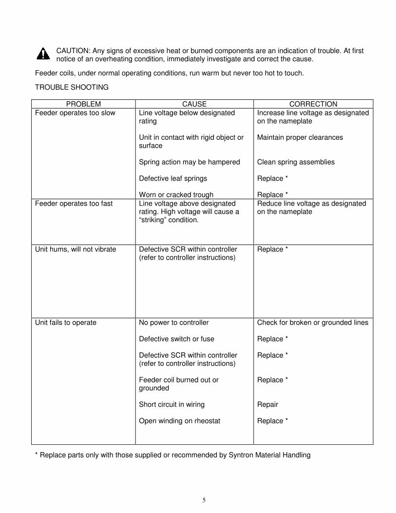
TROUBLE SHOOTING
PROBLEM CAUSE CORRECTION
Feeder operates too slow Line voltage below designated rating Unit in contact with rigid object or surface Spring action may be hampered Defective leaf springs Worn or cracked trough
Increase line voltage as designated on the nameplate Maintain proper clearances Clean spring assemblies Replace * Replace *
Feeder operates too fast Line voltage above designated rating. High voltage will cause a “striking” condition.
Reduce line voltage as designated on the nameplate
Unit hums, will not vibrate Defective SCR within controller (refer to controller instructions)
Replace *
Unit fails to operate No power to controller Defective switch or fuse Defective SCR within controller (refer to controller instructions) Feeder coil burned out or grounded Short circuit in wiring Open winding on rheostat
Check for broken or grounded lines Replace * Replace * Replace * Repair Replace *
* Replace parts only with those supplied or recommended by Syntron Material Handling
6
SPRING REPLACEMENT Replacement springs must be of the same size and thickness as those removed. Syntron Material Handling recommends replacing all springs rather than just one. Before replacing springs, disconnect the feeder from the power supply. Work on one spring assembly at a time (first the rear spring stack). Make a note of the location and arrangement of each spring, spacer and clamp. Remove the bolts which secure the leaf springs to the base, then the bolts which hold the springs to the trough mounting bracket. Install the new spring assembly in reverse order of that removed. Replace cap screws and torque as specified on page 6. AIR GAP The air gap is the spacing that exists between the faces of the armature and core assemblies. Proper adjustment of this space is extremely important for good feeder operation. If the air gap is adjusted so the armature and core are too close, the faces of these items will make contact during feeder operation. This is called “striking”.
CAUTION: If a loud striking noise occurs, immediately turn the unit off. When operating normally, the feeder should perform with a smooth even stroke.
If the air gap is adjusted so the armature and core are too far apart, the feeder current may increase to a dangerous level. A high current condition will result in coil burn-out, failure of control components or a reduced material feed rate. The air gap is properly set at the factory, re-adjustment should rarely be required. However, if high voltage is applied to the feeder or if the air gap has been altered due to improper handling an adjustment may be in order. While following this procedure refer to the illustration on page 7. Loosen hex nut (K) and insert a screwdriver into the slot on the end of the core (M). Turning the core clockwise will narrow the air gap; counterclockwise will widen the air gap. The proper air gap is reached when the air gap is as narrow as possible without a striking condition. The designated current rating must not be exceeded. When the proper air gap has been obtained, lock the core in place by tightening the hex nut (K). F/DF-T01-AS units operate with the trough stroke between .045” to .050” (1.1 to 1.3 mm). This is checked at the stroke gauge on the trough assembly. The air gap adjustment is a very delicate procedure and may require some time to properly obtain the desired setting. The correct air gap spacing will be obtained when the armature and core faces are as close as possible without “striking” when maximum current is applied to the feeder magnet.
7
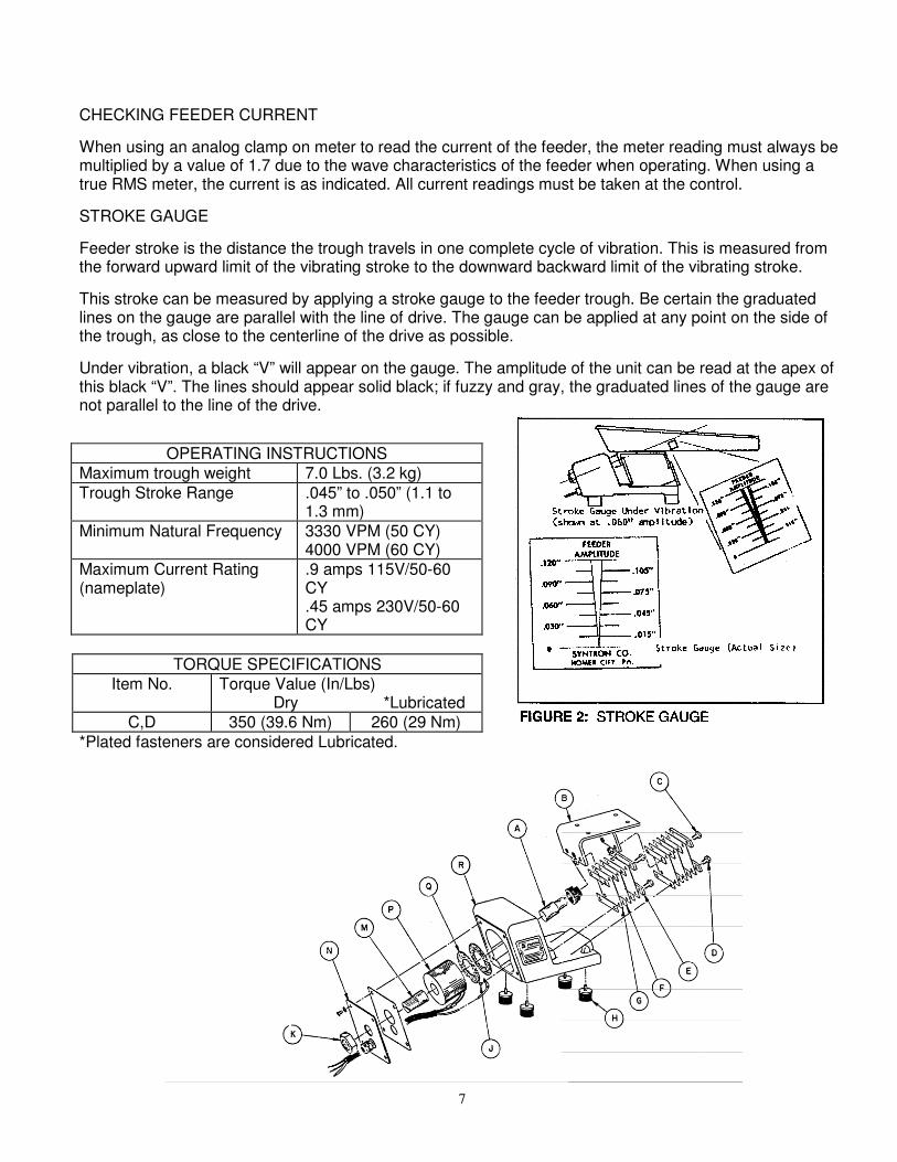
CHECKING FEEDER CURRENT
When using an analog clamp on meter to read the current of the feeder, the meter reading must always be multiplied by a value of 1.7 due to the wave characteristics of the feeder when operating. When using a true RMS meter, the current is as indicated. All current readings must be taken at the control.
STROKE GAUGE
Feeder stroke is the distance the trough travels in one complete cycle of vibration. This is measured from the forward upward limit of the vibrating stroke to the downward backward limit of the vibrating stroke.
This stroke can be measured by applying a stroke gauge to the feeder trough. Be certain the graduated lines on the gauge are parallel with the line of drive. The gauge can be applied at any point on the side of the trough, as close to the centerline of the drive as possible.
Under vibration, a black “V” will appear on the gauge. The amplitude of the unit can be read at the apex of this black “V”. The lines should appear solid black; if fuzzy and gray, the graduated lines of the gauge are not parallel to the line of the drive.
OPERATING INSTRUCTIONS
Maximum trough weight 7.0 Lbs. (3.2 kg)
Trough Stroke Range .045” to .050” (1.1 to 1.3 mm)
Minimum Natural Frequency 3330 VPM (50 CY) 4000 VPM (60 CY)
Maximum Current Rating (nameplate)
.9 amps 115V/50-60 CY .45 amps 230V/50-60 CY
TORQUE SPECIFICATIONS
Item No. Torque Value (In/Lbs) Dry *Lubricated
C,D 350 (39.6 Nm) 260 (29 Nm)
*Plated fasteners are considered Lubricated.
8
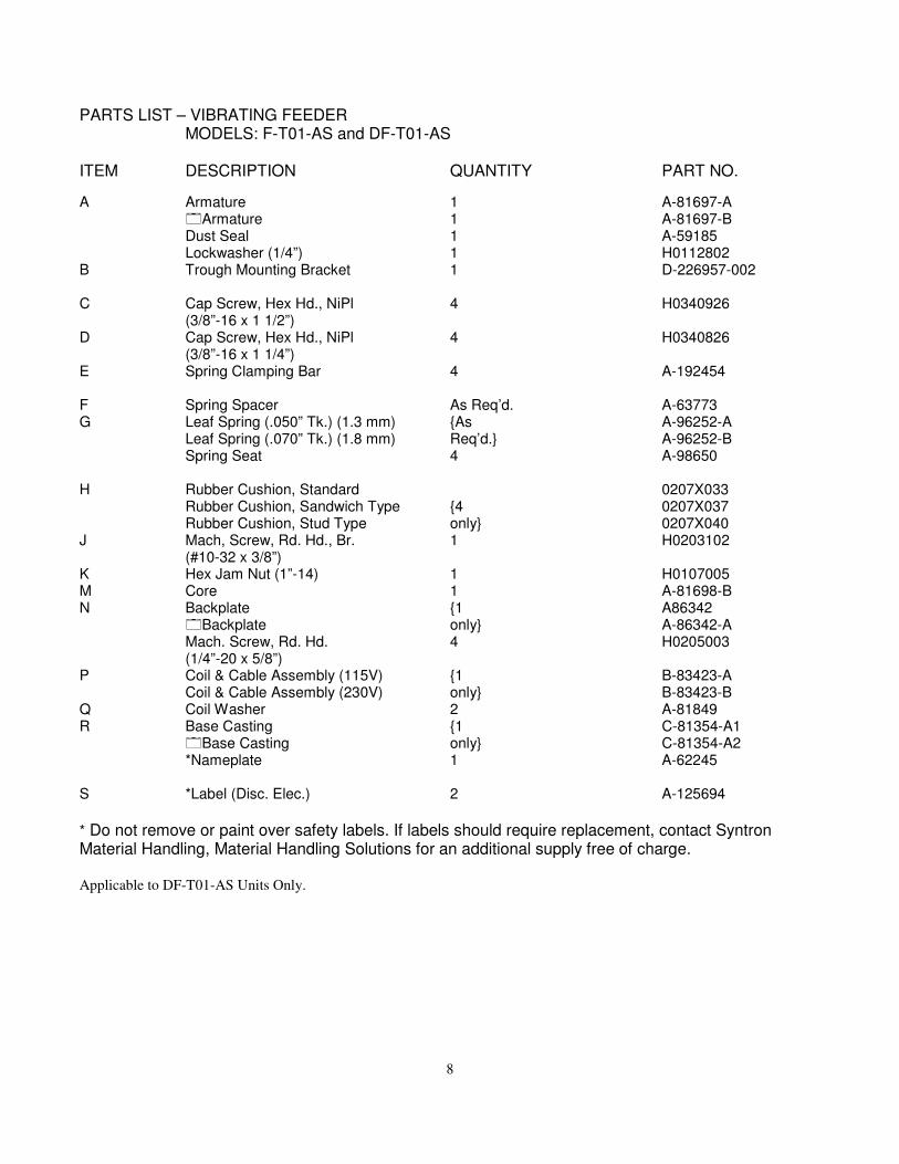
PARTS LIST – VIBRATING FEEDER MODELS: F-T01-AS and DF-T01-AS ITEM DESCRIPTION QUANTITY PART NO.
A Armature 1 A-81697-A �Armature 1 A-81697-B Dust Seal 1 A-59185 Lockwasher (1/4”) 1 H0112802 B Trough Mounting Bracket 1 D-226957-002 C Cap Screw, Hex Hd., NiPl 4 H0340926 (3/8”-16 x 1 1/2”) D Cap Screw, Hex Hd., NiPl 4 H0340826 (3/8”-16 x 1 1/4”) E Spring Clamping Bar 4 A-192454 F Spring Spacer As Req’d. A-63773 G Leaf Spring (.050” Tk.) (1.3 mm) {As A-96252-A Leaf Spring (.070” Tk.) (1.8 mm) Req’d.} A-96252-B Spring Seat 4 A-98650 H Rubber Cushion, Standard 0207X033 Rubber Cushion, Sandwich Type {4 0207X037 Rubber Cushion, Stud Type only} 0207X040 J Mach, Screw, Rd. Hd., Br. 1 H0203102 (#10-32 x 3/8”) K Hex Jam Nut (1”-14) 1 H0107005 M Core 1 A-81698-B N Backplate {1 A86342 �Backplate only} A-86342-A Mach. Screw, Rd. Hd. 4 H0205003 (1/4”-20 x 5/8”) P Coil & Cable Assembly (115V) {1 B-83423-A Coil & Cable Assembly (230V) only} B-83423-B Q Coil Washer 2 A-81849 R Base Casting {1 C-81354-A1 �Base Casting only} C-81354-A2 *Nameplate 1 A-62245 S *Label (Disc. Elec.) 2 A-125694
* Do not remove or paint over safety labels. If labels should require replacement, contact Syntron Material Handling, Material Handling Solutions for an additional supply free of charge. Applicable to DF-T01-AS Units Only.

9
Important
Syntron Material Handling reserves the right to alter at any time, without notice and without liability or
other obligations on its part, materials, equipment specifications, and models. Syntron Material
Handling also reserves the right to discontinue the manufacture of models, parts, and components
thereof.
Your satisfaction is very important to us. Please direct any comments, questions, or concerns to
our Marketing Communications Department.
Corporate Office
P.O. Box 1370 Tupelo, Mississippi 38802
Phone: 662.869.5711 Fax: 662.869.7449
Tupelo 2730 Hwy 145 South Saltillo, Mississippi 38866 Phone: 662.869.5711 Fax: 662.869.7493 Toll Free: 800.356.4898 [email protected]
Changshu #2 Road No. 1 Changshu Export Processing Zone Changshu, Jiangsu, China 215513 Phone: +86 0512.52299002 Fax: +86 0512.52297228 [email protected]
Form No. SM0758_122214 Printed in U.S.A