slm1: linear motion system for refrigerator doors...
TRANSCRIPT
EN
PRJ1080_03_07_03_QR REV. 06
SLM1: LINEAR MOTION SYSTEM FOR
REFRIGERATOR DOORS
QUICK REFERENCE NOTE: The complete user manual can be downloaded from our website:
www.fgespa.com
FGE Elettronica S.p.a
Via C.A. Dalla Chiesa, 10
25017 – Lonato del Garda (BS)
P.I. IT01975940162
Tel: 030 9919700
Fax: 030 9913955
www.fgespa.com
EN SLM1: Quick Reference – Rev06 Page 2/9
1 General information
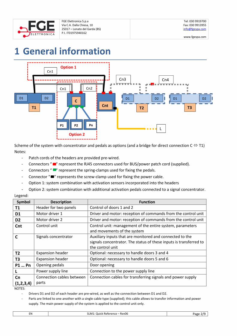
Scheme of the system with concentrator and pedals as options (and a bridge for direct connection C � T1)
Notes:
- Patch cords of the headers are provided pre-wired.
- Connectors “ “ represent the RJ45 connectors used for BUS/power patch cord (supplied).
- Connectors “ “ represent the spring-clamps used for fixing the pedals.
- Connector “ “ represents the screw-clamp used for fixing the power cable.
- Option 1: system combination with activation sensors incorporated into the headers
- Option 2: system combination with additional activation pedals connected to a signal concentrator.
Legend:
Symbol Description Function
T1 Header for two panels Control of doors 1 and 2
D1 Motor driver 1 Driver and motor: reception of commands from the control unit
D2 Motor driver 2 Driver and motor: reception of commands from the control unit
Cnt Control unit Control unit: management of the entire system, parameters
and movements of the system
C Signals concentrator Auxiliary inputs that are monitored and connected to the
signals concentrator. The status of these inputs is transferred to
the control unit
T2 Expansion header Optional: necessary to handle doors 3 and 4
T3 Expansion header Optional: necessary to handle doors 5 and 6
P1 … Pn Opening pedals Door opening
L Power supply line Connection to the power supply line
Cn
(1,2,3,4)
Connection cables between
parts
Connection cables for transferring signals and power supply
NOTES:
- Drivers D1 and D2 of each header are pre-wired, as well as the connection between D1 and D2.
- Parts are linked to one another with a single cable type (supplied); this cable allows to transfer information and power
supply. The main power supply of the system is applied to the control unit only.
Option 2
D1 D2
T1 Cnt
C D1 D2
T3
D1 D2
T2
P1 P2 Pn
Cn1 Cn2
Cn3 Cn4
L
Option 1 Cn1
FGE Elettronica S.p.a
Via C.A. Dalla Chiesa, 10
25017 – Lonato del Garda (BS)
P.I. IT01975940162
Tel: 030 9919700
Fax: 030 9913955
www.fgespa.com
EN SLM1: Quick Reference – Rev06 Page 3/9
2 Installation
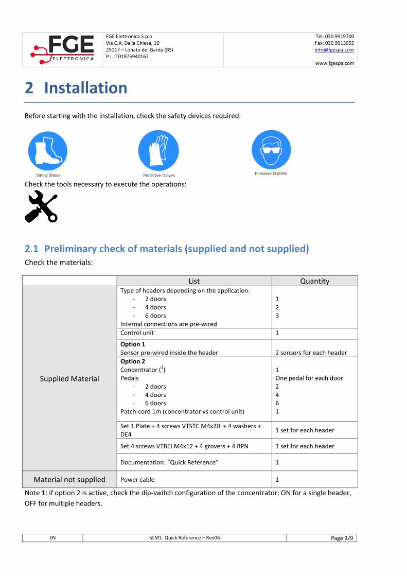
Before starting with the installation, check the safety devices required:
Check the tools necessary to execute the operations:
2.1 Preliminary check of materials (supplied and not supplied)
Check the materials:
List Quantity
Supplied Material
Type of headers depending on the application:
- 2 doors
- 4 doors
- 6 doors
Internal connections are pre-wired
1
2
3
Control unit 1
Option 1
Sensor pre-wired inside the header
2 sensors for each header
Option 2
Concentrator (1)
Pedals
- 2 doors
- 4 doors
- 6 doors
Patch-cord 1m (concentrator vs control unit)
1
One pedal for each door
2
4
6
1
Set 1 Plate + 4 screws VTSTC M4x20 + 4 washers +
DE4 1 set for each header
Set 4 screws VTBEI M4x12 + 4 grovers + 4 RPN 1 set for each header
Documentation: “Quick Reference” 1
Material not supplied Power cable 1
Note 1: if option 2 is active, check the dip-switch configuration of the concentrator: ON for a single header,
OFF for multiple headers.
FGE Elettronica S.p.a
Via C.A. Dalla Chiesa, 10
25017 – Lonato del Garda (BS)
P.I. IT01975940162
Tel: 030 9919700
Fax: 030 9913955
www.fgespa.com
EN SLM1: Quick Reference – Rev06 Page 4/9
2.2 Preliminary checks on panels
The installation of the automation system must be done by technically competent personnel only, meeting
the professional requirements provided by the legislation in force in the country of installation.
Before starting with the installation of the automation system:
- Check that the structure that has to be automated is stable and sturdy to support the weight of the
automation system. If these conditions are not verified, do not proceed with the installation.
- Make sure that the power patch cord has been prepared near the automation system.
- Verify that the movement of the panels is free and without obstacles along the entire travel.
2.3 Installation of mechanical and electronic parts
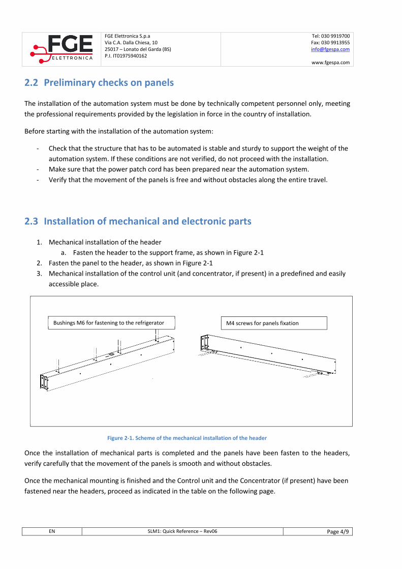
1. Mechanical installation of the header
a. Fasten the header to the support frame, as shown in Figure 2-1
2. Fasten the panel to the header, as shown in Figure 2-1
3. Mechanical installation of the control unit (and concentrator, if present) in a predefined and easily
accessible place.
Figure 2-1. Scheme of the mechanical installation of the header
Once the installation of mechanical parts is completed and the panels have been fasten to the headers,
verify carefully that the movement of the panels is smooth and without obstacles.
Once the mechanical mounting is finished and the Control unit and the Concentrator (if present) have been
fastened near the headers, proceed as indicated in the table on the following page.
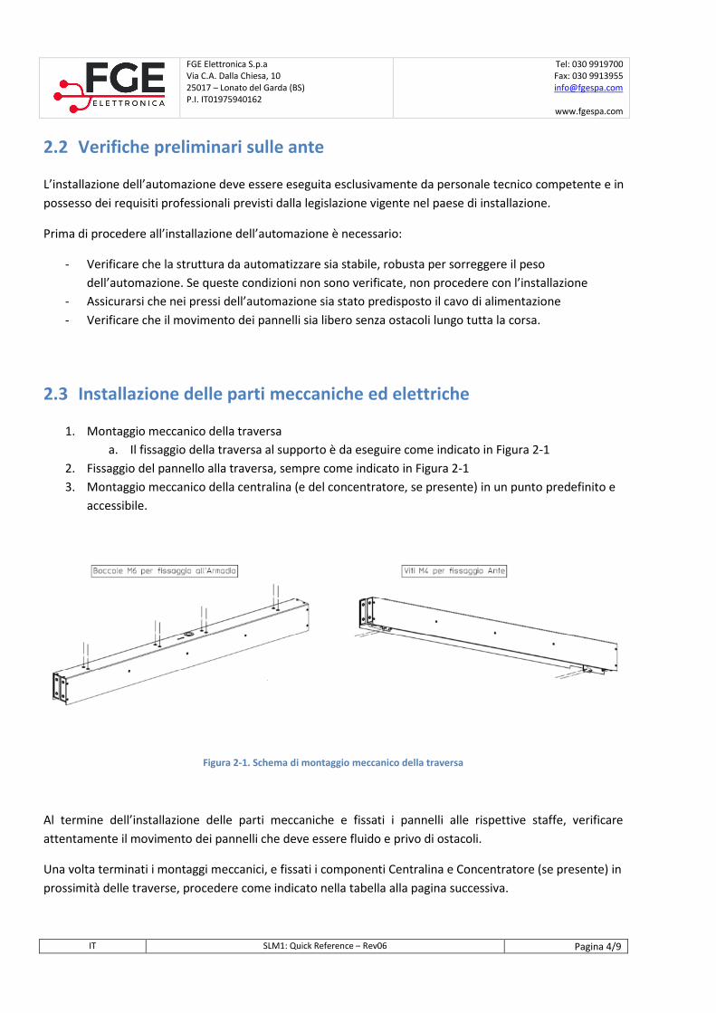
M4 screws for panels fixation Bushings M6 for fastening to the refrigerator
FGE Elettronica S.p.a
Via C.A. Dalla Chiesa, 10
25017 – Lonato del Garda (BS)
P.I. IT01975940162
Tel: 030 9919700
Fax: 030 9913955
www.fgespa.com
EN SLM1: Quick Reference – Rev06 Page 5/9
Step Operation Description
0 Preliminary
checks
Make sure that no supply voltage is present.
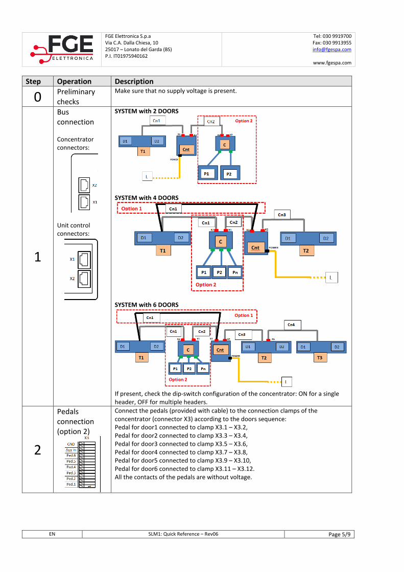
1
Bus
connection
Concentrator
connectors:
Unit control
connectors:
SYSTEM with 2 DOORS
SYSTEM with 4 DOORS
SYSTEM with 6 DOORS
If present, check the dip-switch configuration of the concentrator: ON for a single
header, OFF for multiple headers.
2
Pedals
connection
(option 2)
Connect the pedals (provided with cable) to the connection clamps of the
concentrator (connector X3) according to the doors sequence:
Pedal for door1 connected to clamp X3.1 – X3.2,
Pedal for door2 connected to clamp X3.3 – X3.4,
Pedal for door3 connected to clamp X3.5 – X3.6,
Pedal for door4 connected to clamp X3.7 – X3.8,
Pedal for door5 connected to clamp X3.9 – X3.10,
Pedal for door6 connected to clamp X3.11 – X3.12.
All the contacts of the pedals are without voltage.
FGE Elettronica S.p.a
Via C.A. Dalla Chiesa, 10
25017 – Lonato del Garda (BS)
P.I. IT01975940162
Tel: 030 9919700
Fax: 030 9913955
www.fgespa.com
EN SLM1: Quick Reference – Rev06 Page 6/9
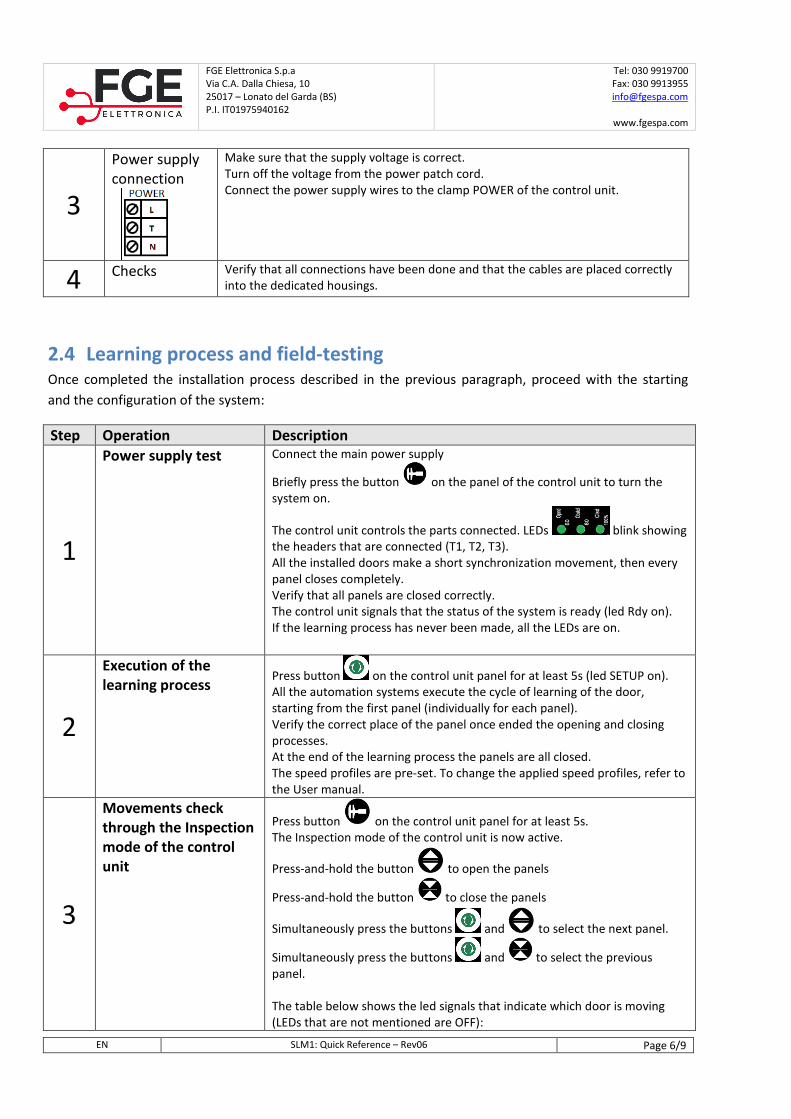
3
Power supply
connection
Make sure that the supply voltage is correct.
Turn off the voltage from the power patch cord.
Connect the power supply wires to the clamp POWER of the control unit.
4 Checks Verify that all connections have been done and that the cables are placed correctly
into the dedicated housings.
2.4 Learning process and field-testing
Once completed the installation process described in the previous paragraph, proceed with the starting
and the configuration of the system:
Step Operation Description
1
Power supply test Connect the main power supply
Briefly press the button on the panel of the control unit to turn the
system on.
The control unit controls the parts connected. LEDs blink showing
the headers that are connected (T1, T2, T3).
All the installed doors make a short synchronization movement, then every
panel closes completely.
Verify that all panels are closed correctly.
The control unit signals that the status of the system is ready (led Rdy on).
If the learning process has never been made, all the LEDs are on.
2
Execution of the
learning process Press button on the control unit panel for at least 5s (led SETUP on).
All the automation systems execute the cycle of learning of the door,
starting from the first panel (individually for each panel).
Verify the correct place of the panel once ended the opening and closing
processes.
At the end of the learning process the panels are all closed.
The speed profiles are pre-set. To change the applied speed profiles, refer to
the User manual.
3
Movements check
through the Inspection
mode of the control
unit
Press button on the control unit panel for at least 5s.
The Inspection mode of the control unit is now active.
Press-and-hold the button to open the panels
Press-and-hold the button to close the panels
Simultaneously press the buttons and to select the next panel.
Simultaneously press the buttons and to select the previous
panel.
The table below shows the led signals that indicate which door is moving
(LEDs that are not mentioned are OFF):
FGE Elettronica S.p.a
Via C.A. Dalla Chiesa, 10
25017 – Lonato del Garda (BS)
P.I. IT01975940162
Tel: 030 9919700
Fax: 030 9913955
www.fgespa.com
EN SLM1: Quick Reference – Rev06 Page 7/9
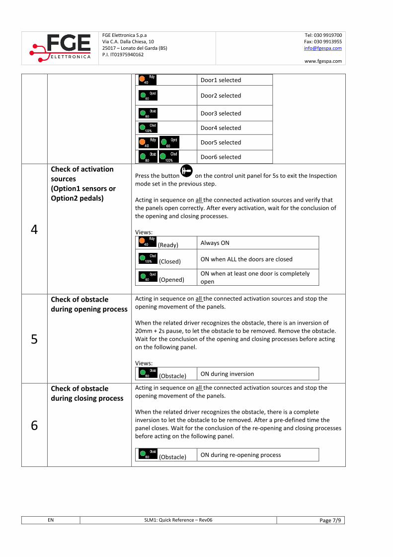
Door1 selected
Door2 selected
Door3 selected
Door4 selected
Door5 selected
Door6 selected
4
Check of activation
sources
(Option1 sensors or
Option2 pedals)
Press the button on the control unit panel for 5s to exit the Inspection
mode set in the previous step.
Acting in sequence on all the connected activation sources and verify that
the panels open correctly. After every activation, wait for the conclusion of
the opening and closing processes.
Views:
(Ready) Always ON
(Closed) ON when ALL the doors are closed
(Opened) ON when at least one door is completely
open
5
Check of obstacle
during opening process
Acting in sequence on all the connected activation sources and stop the
opening movement of the panels.
When the related driver recognizes the obstacle, there is an inversion of
20mm + 2s pause, to let the obstacle to be removed. Remove the obstacle.
Wait for the conclusion of the opening and closing processes before acting
on the following panel.
Views:
(Obstacle) ON during inversion
6
Check of obstacle
during closing process
Acting in sequence on all the connected activation sources and stop the
opening movement of the panels.
When the related driver recognizes the obstacle, there is a complete
inversion to let the obstacle to be removed. After a pre-defined time the
panel closes. Wait for the conclusion of the re-opening and closing processes
before acting on the following panel.
(Obstacle) ON during re-opening process
FGE Elettronica S.p.a
Via C.A. Dalla Chiesa, 10
25017 – Lonato del Garda (BS)
P.I. IT01975940162
Tel: 030 9919700
Fax: 030 9913955
www.fgespa.com
EN SLM1: Quick Reference – Rev06 Page 8/9
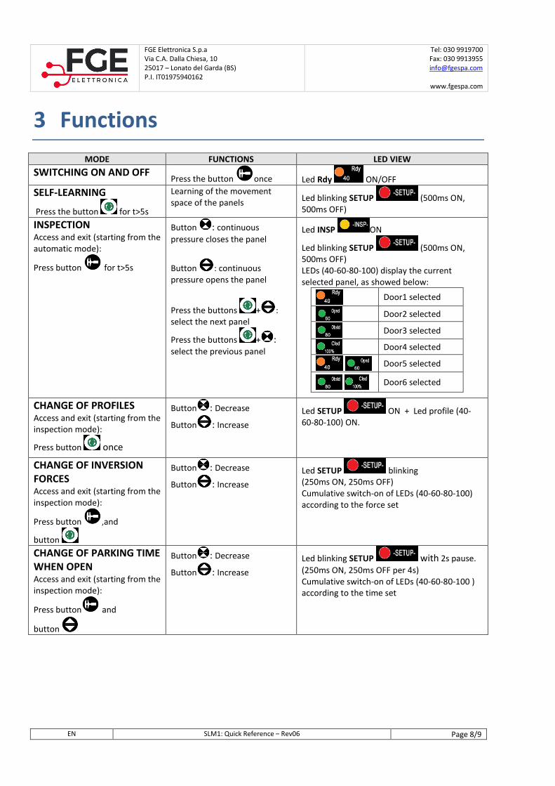
3 Functions
MODE FUNCTIONS LED VIEW
SWITCHING ON AND OFF Press the button once Led Rdy ON/OFF
SELF-LEARNING
Press the button for t>5s
Learning of the movement
space of the panels Led blinking SETUP (500ms ON,
500ms OFF)
INSPECTION Access and exit (starting from the
automatic mode):
Press button for t>5s
Button : continuous
pressure closes the panel
Button : continuous
pressure opens the panel
Press the buttons + :
select the next panel
Press the buttons + :
select the previous panel
Led INSP ON
Led blinking SETUP (500ms ON,
500ms OFF)
LEDs (40-60-80-100) display the current
selected panel, as showed below:
Door1 selected
Door2 selected
Door3 selected
Door4 selected
Door5 selected
Door6 selected
CHANGE OF PROFILES Access and exit (starting from the
inspection mode):
Press button once
Button : Decrease
Button : Increase
Led SETUP ON + Led profile (40-
60-80-100) ON.
CHANGE OF INVERSION
FORCES Access and exit (starting from the
inspection mode):
Press button ,and
button
Button : Decrease
Button : Increase
Led SETUP blinking (250ms ON, 250ms OFF)
Cumulative switch-on of LEDs (40-60-80-100)
according to the force set
CHANGE OF PARKING TIME
WHEN OPEN Access and exit (starting from the
inspection mode):
Press button and
button
Button : Decrease
Button : Increase
Led blinking SETUP with 2s pause.
(250ms ON, 250ms OFF per 4s)
Cumulative switch-on of LEDs (40-60-80-100 )
according to the time set
FGE Elettronica S.p.a
Via C.A. Dalla Chiesa, 10
25017 – Lonato del Garda (BS)
P.I. IT01975940162
Tel: 030 9919700
Fax: 030 9913955
www.fgespa.com
EN SLM1: Quick Reference – Rev06 Page 9/9
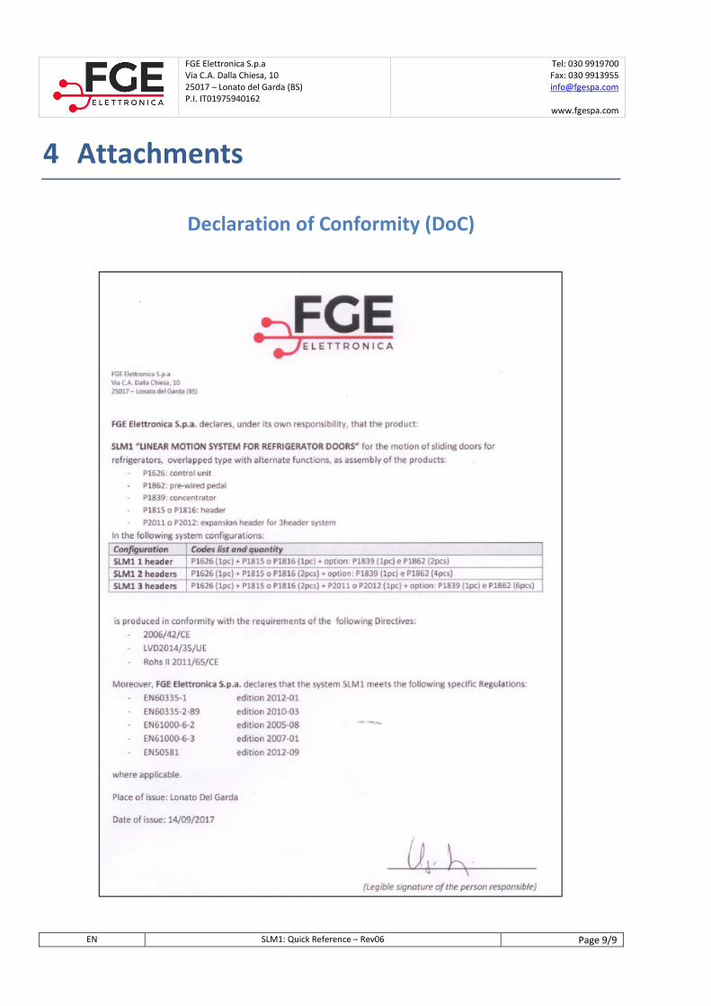
4 Attachments
Declaration of Conformity (DoC)
IT
PRJ1080_03_07_03_QR REV. 06
SLM1: SISTEMA LINEARE DI MOVIMENTAZIONE PORTE PER FRIGORIFERI
QUICK REFERENCE NOTA: il manuale completo può essere scaricato del nostro sito internet
www.fgespa.com
FGE Elettronica S.p.a
Via C.A. Dalla Chiesa, 10
25017 – Lonato del Garda (BS)
P.I. IT01975940162
Tel: 030 9919700
Fax: 030 9913955
www.fgespa.com
IT SLM1: Quick Reference – Rev06 Pagina 2/9
1 Generalità
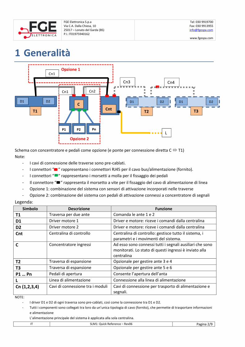
Schema con concentratore e pedali come opzione (e ponte per connessione diretta C � T1)
Note:
- I cavi di connessione delle traverse sono pre-cablati.
- I connettori “ “ rappresentano i connettori RJ45 per il cavo bus/alimentazione (fornito).
- I connettori “ “ rappresentano i morsetti a molla per il fissaggio dei pedali
- Il connettore “ “ rappresenta il morsetto a vite per il fissaggio del cavo di alimentazione di linea
- Opzione 1: combinazione del sistema con sensori di attivazione incorporati nelle traverse
- Opzione 2: combinazione del sistema con pedali di attivazione connessi a concentratore di segnali
Legenda:
Simbolo Descrizione Funzione
T1 Traversa per due ante Comanda le ante 1 e 2
D1 Driver motore 1 Driver e motore: riceve i comandi dalla centralina
D2 Driver motore 2 Driver e motore: riceve i comandi dalla centralina
Cnt Centralina di controllo Centralina di controllo: gestisce tutto il sistema, i
parametri e i movimenti del sistema.
C Concentratore ingressi Ad esso sono connessi tutti i segnali ausiliari che sono
monitorati. Lo stato di questi ingressi è inviato alla
centralina
T2 Traversa di espansione Opzionale per gestire ante 3 e 4
T3 Traversa di espansione Opzionale per gestire ante 5 e 6
P1 … Pn Pedali di apertura Consente l’apertura dell’anta
L Linea di alimentazione Connessione alla linea di alimentazione
Cn (1,2,3,4) Cavi di connessione tra i moduli Cavi di connessione per trasporto di alimentazione e
segnali. NOTE:
- I driver D1 e D2 di ogni traversa sono pre-cablati, così come la connessione tra D1 e D2.
- Tutti i componenti sono collegati tra loro da un’unica tipologia di cavo (fornito), che permette di trasportare informazioni
e alimentazione
L’alimentazione principale del sistema è applicata alla sola centralina.
Opzione 2
D1 D2
T1 Cnt C
D1 D2
T3
D1 D2
T2
P1 P2 Pn
Cn1 Cn2
Cn3 Cn4
L
Opzione 1 Cn1
FGE Elettronica S.p.a
Via C.A. Dalla Chiesa, 10
25017 – Lonato del Garda (BS)
P.I. IT01975940162
Tel: 030 9919700
Fax: 030 9913955
www.fgespa.com
IT SLM1: Quick Reference – Rev06 Pagina 3/9
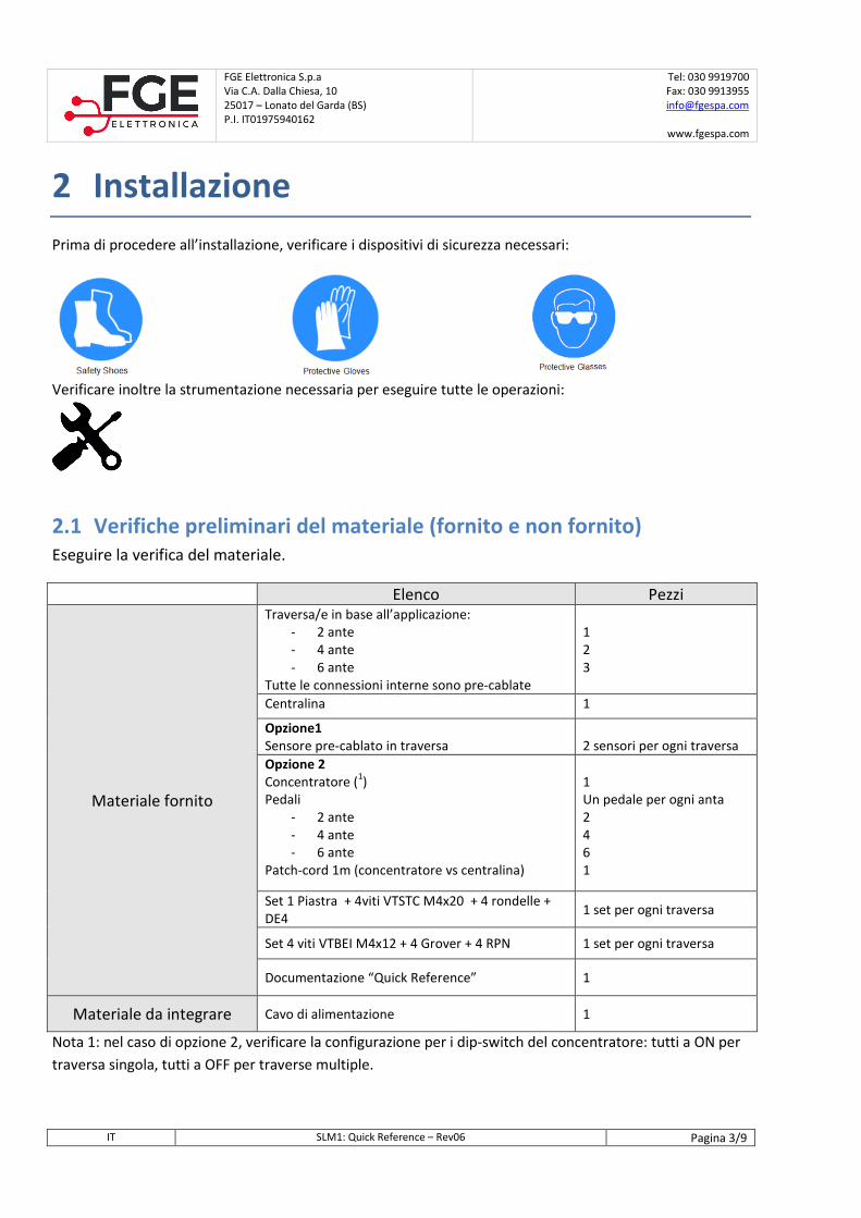
2 Installazione
Prima di procedere all’installazione, verificare i dispositivi di sicurezza necessari:
Verificare inoltre la strumentazione necessaria per eseguire tutte le operazioni:
2.1 Verifiche preliminari del materiale (fornito e non fornito) Eseguire la verifica del materiale.
Elenco Pezzi
Materiale fornito
Traversa/e in base all’applicazione:
- 2 ante
- 4 ante
- 6 ante
Tutte le connessioni interne sono pre-cablate
1
2
3
Centralina 1
Opzione1 Sensore pre-cablato in traversa
2 sensori per ogni traversa
Opzione 2 Concentratore (
1)
Pedali
- 2 ante
- 4 ante
- 6 ante
Patch-cord 1m (concentratore vs centralina)
1
Un pedale per ogni anta
2
4
6
1
Set 1 Piastra + 4viti VTSTC M4x20 + 4 rondelle +
DE4 1 set per ogni traversa
Set 4 viti VTBEI M4x12 + 4 Grover + 4 RPN 1 set per ogni traversa
Documentazione “Quick Reference” 1
Materiale da integrare Cavo di alimentazione 1
Nota 1: nel caso di opzione 2, verificare la configurazione per i dip-switch del concentratore: tutti a ON per
traversa singola, tutti a OFF per traverse multiple.
FGE Elettronica S.p.a
Via C.A. Dalla Chiesa, 10
25017 – Lonato del Garda (BS)
P.I. IT01975940162
Tel: 030 9919700
Fax: 030 9913955
www.fgespa.com
IT SLM1: Quick Reference – Rev06 Pagina 4/9
2.2 Verifiche preliminari sulle ante
L’installazione dell’automazione deve essere eseguita esclusivamente da personale tecnico competente e in
possesso dei requisiti professionali previsti dalla legislazione vigente nel paese di installazione.
Prima di procedere all’installazione dell’automazione è necessario:
- Verificare che la struttura da automatizzare sia stabile, robusta per sorreggere il peso
dell’automazione. Se queste condizioni non sono verificate, non procedere con l’installazione
- Assicurarsi che nei pressi dell’automazione sia stato predisposto il cavo di alimentazione
- Verificare che il movimento dei pannelli sia libero senza ostacoli lungo tutta la corsa.
2.3 Installazione delle parti meccaniche ed elettriche
1. Montaggio meccanico della traversa
a. Il fissaggio della traversa al supporto è da eseguire come indicato in Figura 2-1
2. Fissaggio del pannello alla traversa, sempre come indicato in Figura 2-1
3. Montaggio meccanico della centralina (e del concentratore, se presente) in un punto predefinito e
accessibile.
Figura 2-1. Schema di montaggio meccanico della traversa
Al termine dell’installazione delle parti meccaniche e fissati i pannelli alle rispettive staffe, verificare
attentamente il movimento dei pannelli che deve essere fluido e privo di ostacoli.
Una volta terminati i montaggi meccanici, e fissati i componenti Centralina e Concentratore (se presente) in
prossimità delle traverse, procedere come indicato nella tabella alla pagina successiva.
FGE Elettronica S.p.a
Via C.A. Dalla Chiesa, 10
25017 – Lonato del Garda (BS)
P.I. IT01975940162
Tel: 030 9919700
Fax: 030 9913955
www.fgespa.com
IT SLM1: Quick Reference – Rev06 Pagina 5/9
Passo Operazione Descrizione
0 Verifiche
preliminari
Accertarsi che non sia presente tensione di alimentazione.
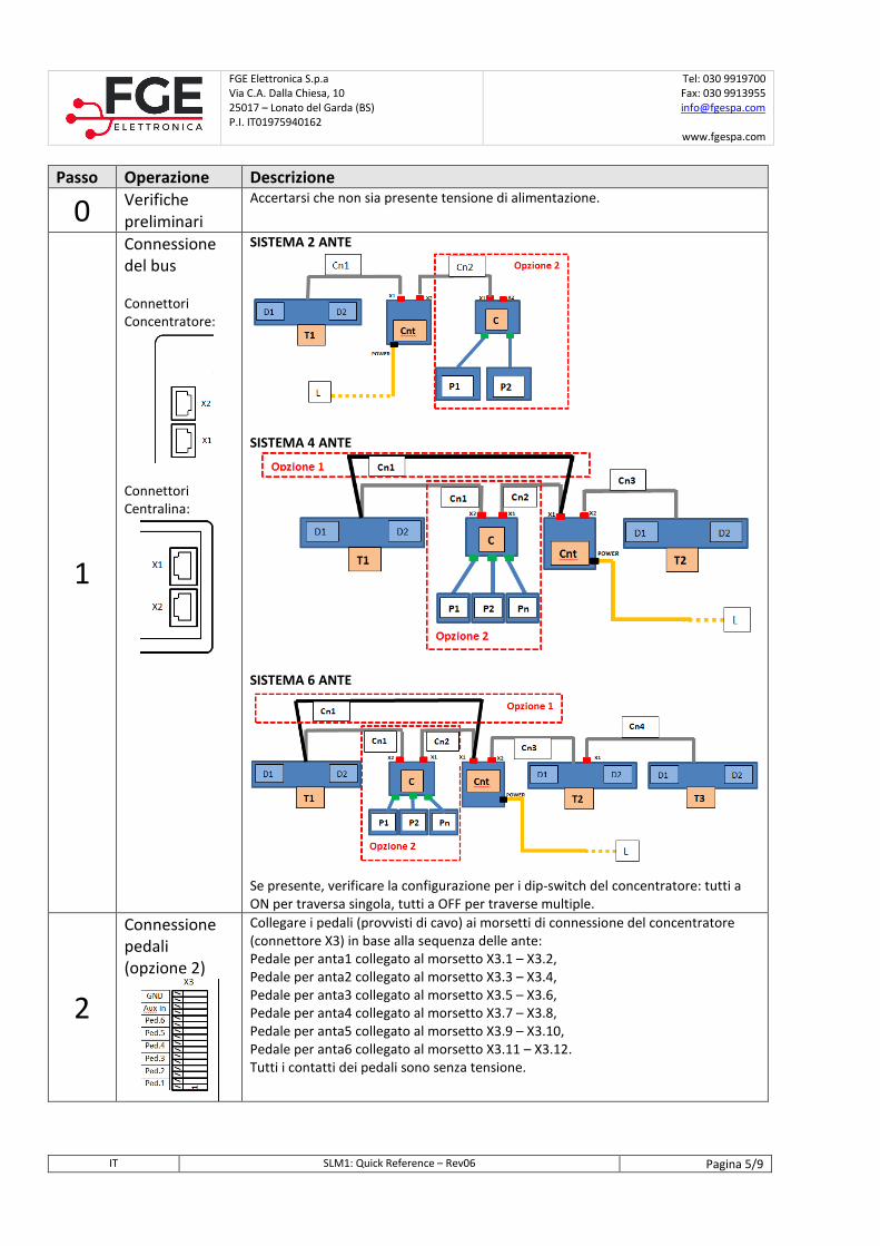
1
Connessione
del bus
Connettori
Concentratore:
Connettori
Centralina:
SISTEMA 2 ANTE
SISTEMA 4 ANTE
SISTEMA 6 ANTE
Se presente, verificare la configurazione per i dip-switch del concentratore: tutti a
ON per traversa singola, tutti a OFF per traverse multiple.
2
Connessione
pedali
(opzione 2)
Collegare i pedali (provvisti di cavo) ai morsetti di connessione del concentratore
(connettore X3) in base alla sequenza delle ante:
Pedale per anta1 collegato al morsetto X3.1 – X3.2,
Pedale per anta2 collegato al morsetto X3.3 – X3.4,
Pedale per anta3 collegato al morsetto X3.5 – X3.6,
Pedale per anta4 collegato al morsetto X3.7 – X3.8,
Pedale per anta5 collegato al morsetto X3.9 – X3.10,
Pedale per anta6 collegato al morsetto X3.11 – X3.12.
Tutti i contatti dei pedali sono senza tensione.
FGE Elettronica S.p.a
Via C.A. Dalla Chiesa, 10
25017 – Lonato del Garda (BS)
P.I. IT01975940162
Tel: 030 9919700
Fax: 030 9913955
www.fgespa.com
IT SLM1: Quick Reference – Rev06 Pagina 6/9
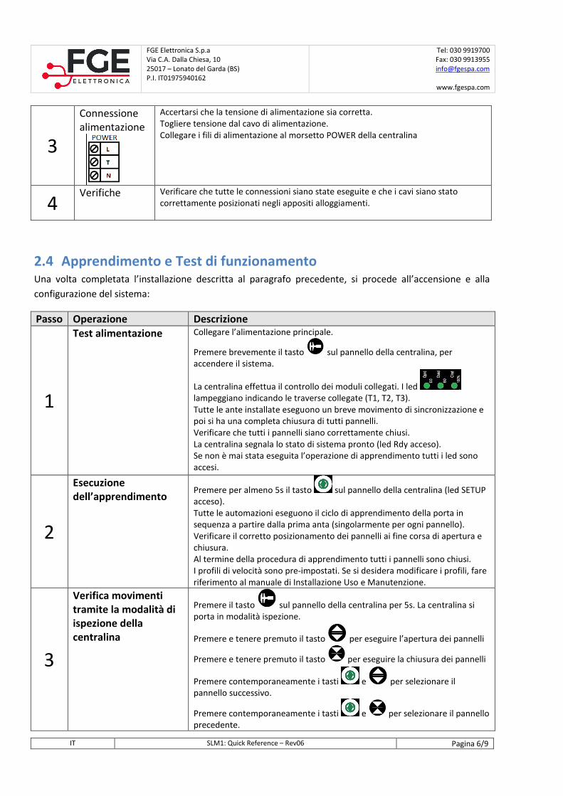
3
Connessione
alimentazione
Accertarsi che la tensione di alimentazione sia corretta.
Togliere tensione dal cavo di alimentazione.
Collegare i fili di alimentazione al morsetto POWER della centralina
4 Verifiche Verificare che tutte le connessioni siano state eseguite e che i cavi siano stato
correttamente posizionati negli appositi alloggiamenti.
2.4 Apprendimento e Test di funzionamento Una volta completata l’installazione descritta al paragrafo precedente, si procede all’accensione e alla
configurazione del sistema:
Passo Operazione Descrizione
1
Test alimentazione Collegare l’alimentazione principale.
Premere brevemente il tasto sul pannello della centralina, per
accendere il sistema.
La centralina effettua il controllo dei moduli collegati. I led
lampeggiano indicando le traverse collegate (T1, T2, T3).
Tutte le ante installate eseguono un breve movimento di sincronizzazione e
poi si ha una completa chiusura di tutti pannelli.
Verificare che tutti i pannelli siano correttamente chiusi.
La centralina segnala lo stato di sistema pronto (led Rdy acceso).
Se non è mai stata eseguita l’operazione di apprendimento tutti i led sono
accesi.
2
Esecuzione dell’apprendimento
Premere per almeno 5s il tasto sul pannello della centralina (led SETUP
acceso).
Tutte le automazioni eseguono il ciclo di apprendimento della porta in
sequenza a partire dalla prima anta (singolarmente per ogni pannello).
Verificare il corretto posizionamento dei pannelli ai fine corsa di apertura e
chiusura.
Al termine della procedura di apprendimento tutti i pannelli sono chiusi.
I profili di velocità sono pre-impostati. Se si desidera modificare i profili, fare
riferimento al manuale di Installazione Uso e Manutenzione.
3
Verifica movimenti tramite la modalità di ispezione della centralina
Premere il tasto sul pannello della centralina per 5s. La centralina si
porta in modalità ispezione.
Premere e tenere premuto il tasto per eseguire l’apertura dei pannelli
Premere e tenere premuto il tasto per eseguire la chiusura dei pannelli
Premere contemporaneamente i tasti e per selezionare il
pannello successivo.
Premere contemporaneamente i tasti e per selezionare il pannello
precedente.
FGE Elettronica S.p.a
Via C.A. Dalla Chiesa, 10
25017 – Lonato del Garda (BS)
P.I. IT01975940162
Tel: 030 9919700
Fax: 030 9913955
www.fgespa.com
IT SLM1: Quick Reference – Rev06 Pagina 7/9
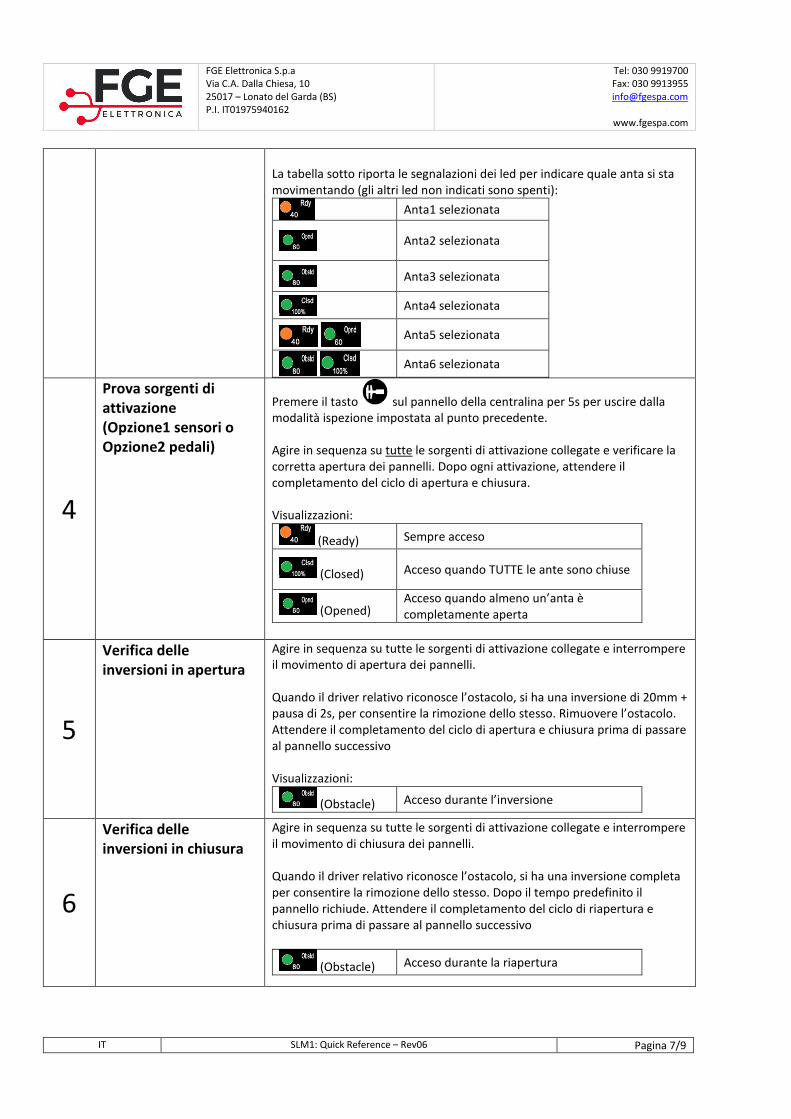
La tabella sotto riporta le segnalazioni dei led per indicare quale anta si sta
movimentando (gli altri led non indicati sono spenti):
Anta1 selezionata
Anta2 selezionata
Anta3 selezionata
Anta4 selezionata
Anta5 selezionata
Anta6 selezionata
4
Prova sorgenti di attivazione (Opzione1 sensori o Opzione2 pedali)
Premere il tasto sul pannello della centralina per 5s per uscire dalla
modalità ispezione impostata al punto precedente.
Agire in sequenza su tutte le sorgenti di attivazione collegate e verificare la
corretta apertura dei pannelli. Dopo ogni attivazione, attendere il
completamento del ciclo di apertura e chiusura.
Visualizzazioni:
(Ready) Sempre acceso
(Closed) Acceso quando TUTTE le ante sono chiuse
(Opened) Acceso quando almeno un’anta è
completamente aperta
5
Verifica delle inversioni in apertura
Agire in sequenza su tutte le sorgenti di attivazione collegate e interrompere
il movimento di apertura dei pannelli.
Quando il driver relativo riconosce l’ostacolo, si ha una inversione di 20mm +
pausa di 2s, per consentire la rimozione dello stesso. Rimuovere l’ostacolo.
Attendere il completamento del ciclo di apertura e chiusura prima di passare
al pannello successivo
Visualizzazioni:
(Obstacle) Acceso durante l’inversione
6
Verifica delle inversioni in chiusura
Agire in sequenza su tutte le sorgenti di attivazione collegate e interrompere
il movimento di chiusura dei pannelli.
Quando il driver relativo riconosce l’ostacolo, si ha una inversione completa
per consentire la rimozione dello stesso. Dopo il tempo predefinito il
pannello richiude. Attendere il completamento del ciclo di riapertura e
chiusura prima di passare al pannello successivo
(Obstacle) Acceso durante la riapertura
FGE Elettronica S.p.a
Via C.A. Dalla Chiesa, 10
25017 – Lonato del Garda (BS)
P.I. IT01975940162
Tel: 030 9919700
Fax: 030 9913955
www.fgespa.com
IT SLM1: Quick Reference – Rev06 Pagina 8/9
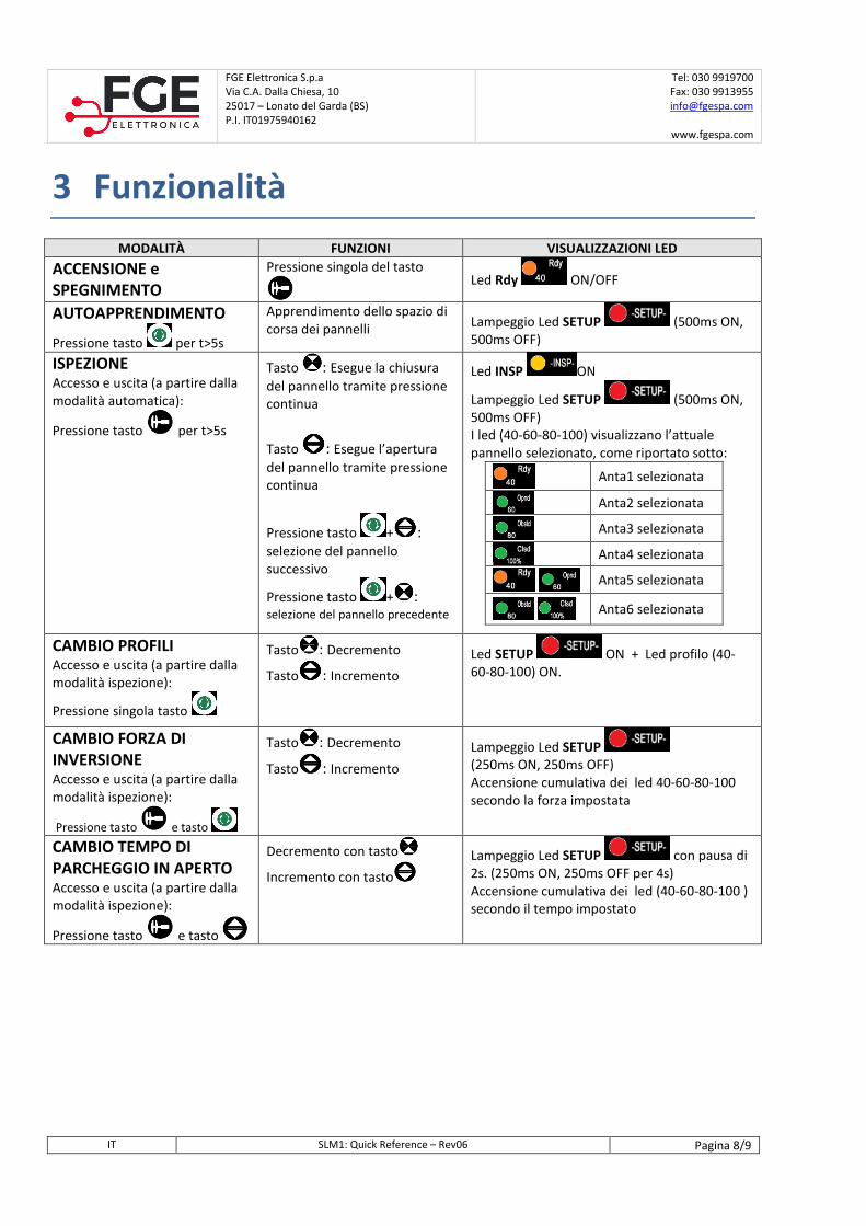
3 Funzionalità
MODALITÀ FUNZIONI VISUALIZZAZIONI LED
ACCENSIONE e SPEGNIMENTO
Pressione singola del tasto
Led Rdy ON/OFF
AUTOAPPRENDIMENTO
Pressione tasto per t>5s
Apprendimento dello spazio di
corsa dei pannelli Lampeggio Led SETUP (500ms ON,
500ms OFF)
ISPEZIONE Accesso e uscita (a partire dalla
modalità automatica):
Pressione tasto per t>5s
Tasto : Esegue la chiusura
del pannello tramite pressione
continua
Tasto : Esegue l’apertura
del pannello tramite pressione
continua
Pressione tasto + :
selezione del pannello
successivo
Pressione tasto + : selezione del pannello precedente
Led INSP ON
Lampeggio Led SETUP (500ms ON,
500ms OFF)
I led (40-60-80-100) visualizzano l’attuale
pannello selezionato, come riportato sotto:
Anta1 selezionata
Anta2 selezionata
Anta3 selezionata
Anta4 selezionata
Anta5 selezionata
Anta6 selezionata
CAMBIO PROFILI Accesso e uscita (a partire dalla
modalità ispezione):
Pressione singola tasto
Tasto : Decremento
Tasto : Incremento
Led SETUP ON + Led profilo (40-
60-80-100) ON.
CAMBIO FORZA DI INVERSIONE Accesso e uscita (a partire dalla
modalità ispezione):
Pressione tasto e tasto
Tasto : Decremento
Tasto : Incremento
Lampeggio Led SETUP (250ms ON, 250ms OFF)
Accensione cumulativa dei led 40-60-80-100
secondo la forza impostata
CAMBIO TEMPO DI PARCHEGGIO IN APERTO Accesso e uscita (a partire dalla
modalità ispezione):
Pressione tasto e tasto
Decremento con tasto
Incremento con tasto
Lampeggio Led SETUP con pausa di
2s. (250ms ON, 250ms OFF per 4s)
Accensione cumulativa dei led (40-60-80-100 )
secondo il tempo impostato
FGE Elettronica S.p.a
Via C.A. Dalla Chiesa, 10
25017 – Lonato del Garda (BS)
P.I. IT01975940162
Tel: 030 9919700
Fax: 030 9913955
www.fgespa.com
IT SLM1: Quick Reference – Rev06 Pagina 9/9
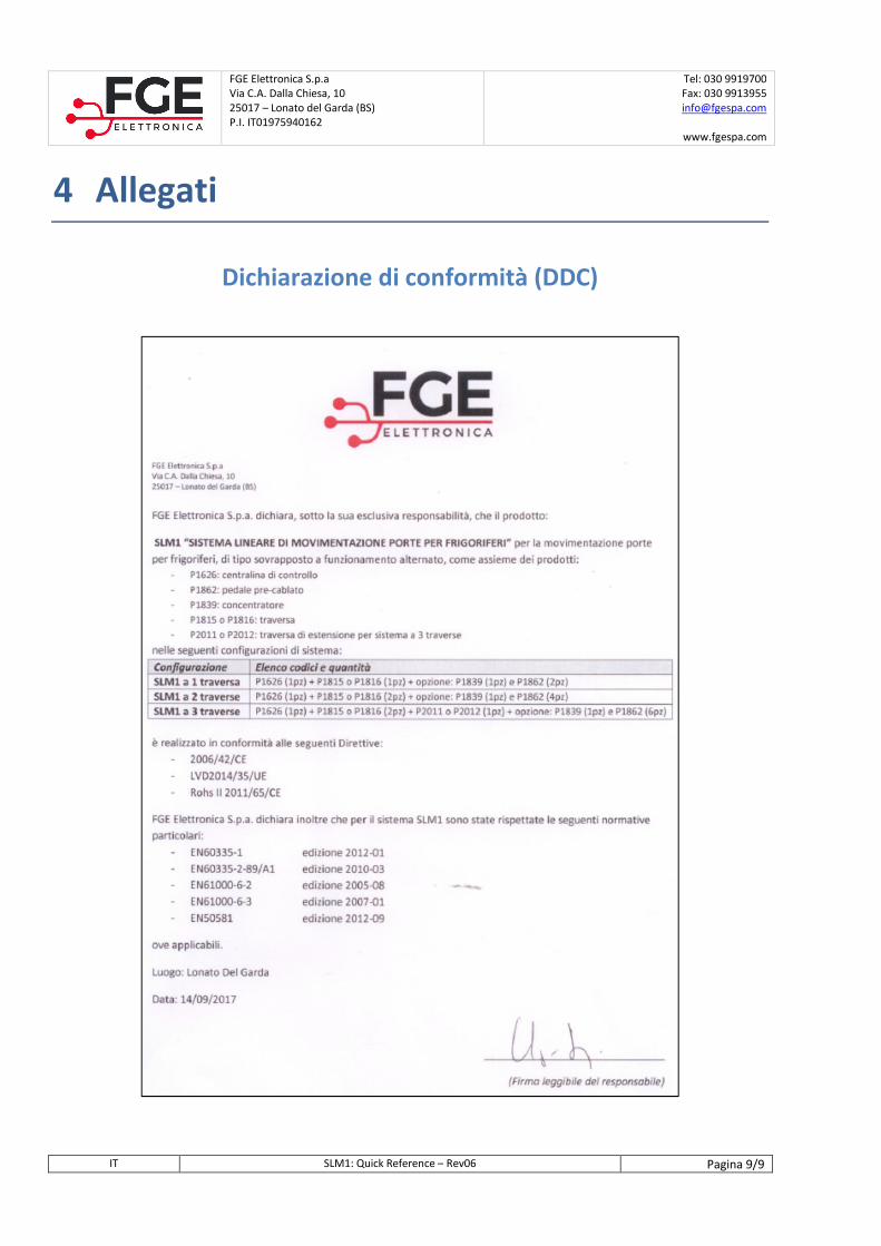
4 Allegati
Dichiarazione di conformità (DDC)

NOTE:

NOTE: