sliding mode control of a magnetic levitation...
TRANSCRIPT

SLIDING MODE CONTROL OF A MAGNETICLEVITATION SYSTEM
N. F. AL-MUTHAIRI AND M. ZRIBI
Received 18 October 2003 and in revised form 23 February 2004
Sliding mode control schemes of the static and dynamic types are proposed for the con-trol of a magnetic levitation system. The proposed controllers guarantee the asymptoticregulation of the states of the system to their desired values. Simulation results of theproposed controllers are given to illustrate the effectiveness of them. Robustness of thecontrol schemes to changes in the parameters of the system is also investigated.
1. Introduction
Magnetic levitation systems have practical importance in many engineering systems suchas in high-speed maglev passenger trains, frictionless bearings, levitation of wind tunnelmodels, vibration isolation of sensitive machinery, levitation of molten metal in induc-tion furnaces, and levitation of metal slabs during manufacturing. The maglev systemscan be classified as attractive systems or repulsive systems based on the source of levi-tation forces. These kind of systems are usually open-loop unstable and are described byhighly nonlinear differential equations which present additional difficulties in controllingthese systems. Therefore, it is an important task to construct high-performance feedbackcontrollers for regulating the position of the levitated object.
In recent years, a lot of works have been reported in the literature for controlling mag-netic levitation systems. The feedback linearization technique has been used to designcontrol laws for magnetic levitation systems [2, 9, 30]. The input-output, input-state, andexact linearization techniques have been used to develop nonlinear controllers [6, 11, 38].Other types of nonlinear controllers based on nonlinear methods have been reportedin the literature [14, 18, 35, 40]. Robust linear controller methods such as H∞ optimalcontrol, µ-synthesis, and Q-parameterization have also been applied to control magneticlevitation systems [12, 13, 23]. Control laws based on phase space [39], linear controllerdesign [10], the gain scheduling approach [21], and neural network techniques [22] havealso been used to control magnetic levitation systems.
During the last two decades, variable structure systems (VSS) and sliding mode control(SMC) have received significant interest and have become well-established research areas
Copyright © 2004 Hindawi Publishing CorporationMathematical Problems in Engineering 2004:2 (2004) 93–1072000 Mathematics Subject Classification: 93B12URL: http://dx.doi.org/10.1155/S1024123X04310033

94 Sliding mode control of a magnetic levitation system
with great potential for practical applications. The theoretical development aspects ofSMC are well documented in many books and articles [3, 19, 29, 31, 32, 33, 34, 37, 41, 42].The discontinuous nature of the control action in SMC is claimed to result in outstandingrobustness features for both system stabilization and output tracking problems. The verygood performance also includes insensitivity to parameter variations and rejection ofdisturbances. VSS has been applied in many control fields which include robot control[36], motor control [15], flight control [17], control of power systems [4], and processcontrol [20]. In addition, SMC has been used in magnetic bearing systems [1, 24, 25];however, the proposed controllers have been designed based on linearized models aboutnominal operating points, and thus the tracking performance deteriorates rapidly withincreasing deviations from the nominal operating points.
One of the first applications of SMC to magnetic levitation systems was carried out byCho et al. [8]. They showed that a sliding mode controller provides better transient re-sponse than classical controllers. However, they neglected the current dynamics in theirmodel and limited the ball’s motion to a range of 1 mm. Chen et al. [7] designed anadaptive sliding mode controller for a rather different type of magnetic levitation systemscalled dual-axis maglev positioning system. Buckner [5] introduced a procedure for es-timating the uncertainty bounds using artificial neural network and then applied it toSMC of a magnetic levitation system. Hassan and Mohamed [16] used the reaching lawmethod complemented with the sliding mode equivalence technique to design a variablestructure controller for the magnetic levitation system.
In this paper, we propose one static and two dynamic SMC schemes for the mag-netic levitation system. The proposed controllers are based on the SMC schemes devel-oped by Sira-Ramırez et al. [27, 28] and Sira-Ramırez [26]; these control schemes havebeen shown to enjoy advantageous insensitivity with respect to variations in the system’sparameters and to external perturbations. Simulation results indicate that the proposedcontrol schemes work well and are robust to changes in the system’s parameters.
The rest of the paper is organized as follows. Section 2 contains the mathematicalmodel of the magnetic levitation system. Section 3 deals with the design of a static SMCfor the magnetic levitation system. Sections 4 and 5 deal with the design of dynamicsliding mode controllers for the system. Section 6 presents and discusses the simulationresults of the proposed control schemes. Finally, the conclusion is given in Section 7.
2. Model of the magnetic levitation system
The magnetic levitation system considered in this paper consists of a ferromagnetic ballsuspended in a voltage-controlled magnetic field. Only the vertical motion is considered.The objective is to keep the ball at a prescribed reference level. The schematic diagram ofthe system is shown in Figure 2.1. The dynamic model of the system can be written as [2]
dp
dt= v, Ri+
d(L(p)i
)dt
= e,
mdv
dt=mgc−C
(i
p
)2
,(2.1)

N. F. Al-Muthairi and M. Zribi 95
Magnet
Ref
p
Ball
Lightsource
Lightsensor
i
−e+
Figure 2.1. Schematic diagram of the magnetic levitation system.
where p denotes the ball’s position, v is the ball’s velocity, i is the current in the coil of theelectromagnet, e is the applied voltage, R is the coil’s resistance, L is the coil’s inductance,gc is the gravitational constant, C is the magnetic force constant, and m is the mass of thelevitated ball.
The inductance L is a nonlinear function of the ball’s position p. The approximation
L(p)= L1 +2Cp
(2.2)
will be used; L1 is a parameter of the system.Let the states and the control input be chosen such that x1 = p, x2 = v, x3 = i, u = e,
and x = (x1 x2 x3)T is the state vector. Thus, the state-space model of the magneticlevitation system can be written as
dx1
dt= x2,
dx2
dt= gc− C
m
(x3
x1
)2
,
dx3
dt=−R
Lx3 +
2CL
(x2x3
x21
)+
1Lu.
(2.3)
The state-space model of the magnetic levitation system (2.3) will be used in the designof the SMC schemes.
Let x1d, x2d, and x3d be the desired values of x1, x2, and x3, respectively. Note, from(2.3), that the equilibrium point for the system is xe = (x1e 0 x3e)T , where x3e satisfies
x3e =√gcm/Cx1e. Therefore, one may conclude that x2d is equal to zero.
The objective of the control schemes is to drive the states x1, x2, and x3 to their desiredconstant values x1d, x2d, and x3d, respectively.

96 Sliding mode control of a magnetic levitation system
Now, consider the following nonlinear change of coordinates:
z1 = x1− x1d,
z2 = x2,
z3 = gc− C
m
(x3
x1
)2
.
(2.4)
Remark 2.1. If z1, z2, z3 are driven to zero as t→∞, then x1 will converge to x1d, x2 will
converge to zero, and x3 will converge to x3d =√gcm/Cx1d as t→∞.
The dynamic model of the magnetic levitation system in the new coordinates systemcan be written as
z1 = z2,
z2 = z3,
z3 = f (z) + g(z)u,
(2.5)
where
f (z)= 2(gc− z3
)((1− 2C
L(z1 + x1d
))
z2(z1 + x1d
) +R
L
),
g(z)= −2L(z1 + x1d
)√
C
m
(gc− z3
).
(2.6)
It should be noted that the functions f (z) and g(z) correspond in the original coordinatesto the following functions, respectively:
f1(x)= 2Cm
((1− 2C
Lx1
)x2x
23
x31
+R
L
x23
x21
),
g1(x)=− 2Cx3
Lmx21
,
(2.7)
where f1(x)= f (z) and g1(x)= g(z).Let the output of the system be
y = z1 = x1− x1d. (2.8)
Using (2.5), (2.7), and (2.8), the relationship between the input and the output of thesystem can be found as
y(3) = f1(x) + g1(x)u. (2.9)
Using model (2.5), (2.6), (2.7), (2.8), and (2.9), the design of SMC schemes for the mag-netic levitation system will be considered in the next sections.

N. F. Al-Muthairi and M. Zribi 97
3. Design of a static sliding mode control
The design of a static SMC scheme for the magnetic levitation system is discussed in thissection.
The first step in designing an SMC scheme for the system is to design the switchingsurface. Let the switching surface be
= y + λ1 y + λ2y = z1 + λ1z1 + λ2z1 = z3 + λ1z2 + λ2z1, (3.1)
where λ1 and λ2 are positive scalars.Using (2.4), the switching surface can be written as a function of x1, x2, and x3 such
that
= gc− C
m
(x3
x1
)2
+ λ1x2 + λ2(x1− x1d
). (3.2)
Note that the choice of the switching surface guarantees that y = z1 = x1− x1d convergesto 0 as t→∞ when we have sliding (i.e., = 0).
The following proposition gives the first result of the paper.
Proposition 3.1. The discontinuous static feedback controller,
u= 1g1
[− f1− λ1
(gc− C
m
(x3
x1
)2)− λ2x2
−W sign(gc− C
m
(x3
x1
)2
+ λ1x2 + λ2(x1− x1d
))],
(3.3)
when applied to the magnetic levitation system (2.3), asymptotically stabilizes x1, x2, and x3
to their desired values as t→∞.
Proof. Differentiating (3.1) with respect to time and using (2.5), (2.6), (2.7), (2.8), and(2.9), we can write the following:
= y(3) + λ1 y + λ2 y = f1(x) + g1(x)u+ λ1z3 + λ2z2. (3.4)
Substituting u by its value from (3.3), it follows that
= f1 + λ1z3 + λ2z2 +
[− f1− λ1
(gc− C
m
(x3
x1
)2)− λ2x2
−W sign(gc− C
m
(x3
x1
)2
+ λ1x2 + λ2(x1− x1d
))]
=−W sign(gc− C
m
(x3
x1
)2
+ λ1x2 + λ2(x1− x1d
))
=−W sign().
(3.5)

98 Sliding mode control of a magnetic levitation system
The dynamics in (3.5) guarantees the finite-time reachability of to zero from any giveninitial condition (0) provided that the constant gain W is chosen to be strictly posi-tive. Moreover, the dynamics in (3.5) guarantees that < 0 (the condition needed toguarantee switching).
Since is driven to zero in finite time, the output y = z1 is governed after such finiteamount of time by the second-order differential equation y + λ1 y + λ2y = 0. Thus theoutput y(t) = z1(t) will converge asymptotically to 0 as t →∞ because λ1 and λ2 arepositive scalars. Since z1 converges to zero, then z2 and z3 will converge to zero as t→∞.Thus x1, x2, and x3 will also converge to their desired values as t→∞.
Therefore, it can be concluded that the static sliding mode controller given by (3.3)guarantees the asymptotic convergence of the states x1, x2, and x3 to their desired valuesas t→∞.
Remark 3.2. Like any other variable structure controller, the proposed controller is con-fronted with the problem of chattering, which is undesirable in practice. To cope with thisproblem, the boundary layer concept (see [29]) or dynamic SMC schemes can be used.
4. Design of a dynamic sliding mode control
To reduce the chattering due to the static sliding mode controller, a dynamic sliding modecontroller is proposed in this section.
Differentiating (2.9) with respect to time, it follows that
y(4) = f1 + g1u+ g1u, (4.1)
where
f1(x)= 2Cm
[−2R2
L2
x23
x21
+(gc− 4R
Lx2
)x2
3
x31
+(
10RCL2
x2− 3x22 −
2CgcL
)x2
3
x41
+(
12CL
x22 −
C
mx2
3
)x2
3
x51
+(
2C2
Lmx2
3 −12C2
L2x2
2
)x2
3
x61
+(
2L
x2
x1− 4C
L2
x2
x21
+2RL2
)x3
x21u
],
g1(x)=(−RL− 2x2
x1+
4CL
x2
x21
)g1(x)− 2C
mL2x21u.
(4.2)
To design the dynamic sliding mode controller, we will choose the switching surface σsuch that
σ = y(3) +m1 y +m2 y +m3y, (4.3)
where m1, m2, and m3 are parameters to be chosen by the designer such that the polyno-mial p1(s)= s3 +m1s2 +m2s+m3 is a Hurwitz polynomial.

N. F. Al-Muthairi and M. Zribi 99
Using (2.4) and (2.9), the switching surface σ can be written as
σ = f1 + g1u+m1
(gc− C
m
(x3
x1
)2)+m2x2 +m3
(x1− x1d
). (4.4)
The following proposition gives the second result of the paper.
Proposition 4.1. The dynamic control scheme,
u= 1g1
[− f1− g1u−m1
(f1 + g1u
)−m2
(gc− C
m
(x3
x1
)2)−m3x2−Γsign(σ)
], (4.5)
when applied to the magnetic levitation system (2.3), asymptotically stabilizes the states totheir desired values as t→∞.
Proof. Differentiating (4.3) with respect to time and using (2.4), (2.5), (2.8), and (4.1), itfollows that
σ = y(4) +m1y(3) +m2 y +m3 y
= f1 + g1u+ g1u+m1(f1 + g1u
)+m2
(gc− C
m
(x3
x1
)2)+m3x2.
(4.6)
Substituting u by its value from (4.5), we get
σ = f1 + g1u+m1(f1 + g1u
)+m2
(gc− C
m
(x3
x1
)2)+m3x2
+[− f1− g1u−m1
(f1 + g1u
)−m2
(gc− C
m
(x3
x1
)2)−m3x2−Γsign(σ)
]
=−Γsign(σ).
(4.7)
The dynamics in (4.7) guarantees the finite-time reachability of σ to zero from any giveninitial condition σ(0) provided that the constant gain Γ is chosen to be strictly positive.Moreover, the dynamics in (4.7) guarantees that σσ < 0 (the condition needed to guaran-tee switching).
Since σ is driven to zero in finite time, the output y = z1 is governed after such fi-nite amount of time by the third-order differential equation y(3) +m1 y +m2 y +m3y = 0.Thus the output y(t)= z1 will converge to zero as t→∞ because m1, m2, and m3 are pos-itive scalars chosen such that the polynomial p1(s) = s3 +m1s2 +m2s+m3 is a Hurwitzpolynomial. Since z1 converges to zero, then z2 and z3 will converge to zero as t →∞.Thus x1, x2, and x3 will also converge to their desired values as t→∞.
Therefore, it can be concluded that the dynamic sliding mode controller given by (4.5)guarantees the asymptotic convergence of the states x1, x2, and x3 to their desired values.

100 Sliding mode control of a magnetic levitation system
The controller developed in this section needs the computation of the derivatives of thesystem’s dynamics. However, the computation of the derivatives might be problematic.Hence, a dynamic SMC scheme that does not require the computation of the derivativesof the system’s dynamics is proposed in the next section.
5. Design of a modified dynamic sliding mode control
Sira-Ramırez et al. [28] proposed the use of a robust redundant feedback controller, basedon dynamical sliding mode control, for nonlinear systems for which a smooth feedbackcontrol policy is available. Motivated by this work, a modified dynamic sliding modecontroller is now designed for the magnetic levitation system.
Recall that the dynamic model of the magnetic levitation system in the z-coordinatessystem can be written as (2.5), where the output of the system is chosen as
y = z1. (5.1)
It can be shown that the feedback linearization controller
u=−1g
(f + c1z1 + c2z2 + c3z3
)(5.2)
guarantees the asymptotic convergence of z1, z2, and z3 to zero as t→∞.The scalars c1, c2, and c3 are real positive constants such that the polynomial p2(s) =
s3 + c3s2 + c2s+ c1 = 0 is a Hurwitz polynomial.Let the input-dependent switching surface ρ(z,u) be
ρ(z,u)= u+1g
(f + c1z1 + c2z2 + c3z3
)(5.3)
and let W2 be a sufficiently large, strictly positive scalar.The following proposition gives the third result of the paper.
Proposition 5.1. The dynamic control scheme,
u=−1g
(f + c1z1 + c2z2 + c3z3
)+ v, (5.4)
with
v =−W2 sign
(u+
1g
(f + c1z1 + c2z2 + c3z3
)), (5.5)
when applied to the magnetic levitation system (2.5), guarantees the asymptotic convergenceof z1, z2, and z3 to zero as t→∞.
Proof. The dynamics in (5.3), (5.4), and (5.5) guarantees the finite-time reachability ofρ to zero from any given initial condition provided that the constant gain W2 is chosento be strictly positive. Moreover, the dynamics in (5.3), (5.4), and (5.5) guarantees thatρ(z,u)ρ(z,u) < 0 (the condition needed to guarantee switching).

N. F. Al-Muthairi and M. Zribi 101
Since ρ(z,u) is driven to zero in finite time, the output y = z1 is governed on the slidingsurface (ρ(x,u) = 0) by the third-order differential equation y(3) + c3 y + c2 y + c1y = 0.Thus, the output y(t) = z1 will converge asymptotically to zero as t→∞ because c1, c2,and c3 are chosen to be positive scalars such that the polynomial p2(s)= s3 + c3s2 + c2s+ c1
is a Hurwitz polynomial. Since z1 converges to zero, then z2 and z3 will also converge tozero as t→∞.
Using (2.4), it is clear that x1, x2, x3 will also converge to their desired values as t→∞.Thus, it can be concluded that the dynamic sliding mode controller (5.4), (5.5) guaranteesthe asymptotic convergence of the states x1, x2, and x3 to their desired values as t→∞.
Remark 5.2. The controller given in Proposition 5.1 can be transformed into the originalcoordinates of the system by using transformation (2.4). Hence, controller (5.4), (5.5) inthe original coordinates is such
u=− 1g1
(f1 + c1
(x1− x1d
)+ c2x2 + c3
(gc− C
m
(x3
x1
)2))+ v (5.6)
with
v =−W2 sign(u+
1g1
[f1 + c1(x1− x1d) + c2x2 + c3
(gc− C
m
(x3
x1
)2)]). (5.7)
6. Simulation results of the sliding mode controllers
Simulations are performed for the static and the two dynamic sliding mode controllersproposed in the paper. The results are shown in this section.
The parameters of the magnetic levitation system are as follows [2]. The coil’s resis-tance R= 28.7Ω, the inductance L1 = 0.65 H, the gravitational constant gc = 9.81 milli-seconds−2, the magnetic force constant C = 1.410−4, and the mass of the ball m= 11.87 g.
First, the static sliding mode controller (3.3) is applied to the magnetic levitation sys-tem (2.3). The parameters of the controller are chosen such that W = 350, λ1 = 61, andλ2 = 930 (which correspond to closed-loop poles of the reduced-order system of−30 and−31). The simulation results are shown in Figure 6.1. The figure shows the position ver-sus time and the control (the applied voltage) versus time for the system when the massvalue is nominal and when the mass value is changed by ±25%. It can be seen from thefigure that the position converges to its desired value when the mass value is nominal.However, there is a small steady-state error in the position when the mass is changed.Also, some chattering can be seen due to this controller. To further reduce the magnitudeof the steady-state error, the value of W can be increased. However, increasing the valueof W will lead to a larger control magnitude and more chattering. The value of W wasselected so that the magnitudes of the three controllers have similar ranges.
Second, the dynamic sliding mode controller (4.5) is applied to the magnetic levitationsystem (2.3). The parameters of the controller are chosen such that Γ= 50000, m1 = 93,m2 = 2882, and m3 = 29760 (which correspond to closed-loop poles of −30, −31, and−32). The simulation results are shown in Figure 6.2. The figure shows the position versustime and the control versus time for the system when the mass value is nominal and

102 Sliding mode control of a magnetic levitation system
0.02
0.015
0.01
0.0050 0.2 0.4 0.6 0.8 1
Time (s)
Posi
tion
(m)
(a)
30
20
10
00 0.2 0.4 0.6 0.8 1
Time (s)
Con
trol
(v)
(b)
0.02
0.015
0.01
0.0050 0.2 0.4 0.6 0.8 1
Time (s)
Posi
tion
(m)
(c)
30
20
10
00 0.2 0.4 0.6 0.8 1
Time (s)
Con
trol
(v)
(d)
0.02
0.015
0.01
0.0050 0.2 0.4 0.6 0.8 1
Time (s)
Posi
tion
(m)
(e)
30
20
10
00 0.2 0.4 0.6 0.8 1
Time (s)
Con
trol
(v)
(f)
Figure 6.1. The position and the control versus time when using the static sliding mode scheme.(a) Position for m = 11.87g, (b) control for m = 11.87g, (c) position for m = 11.87g+ 25%,(d) control for m = 11.87g + 25%, (e) position for m = 11.87g − 25%, and (f) control form =11.87g − 25%.
when the mass value is changed by±25%. It can be seen from Figure 6.2 that the positionconverges to its desired value even when the mass of the object varies by ±25%. Hence,the controlled system is robust to changes in the mass value. Also, it can be seen fromthe figure that the chattering in the control signal is greatly reduced when the dynamicsliding mode controller is applied.
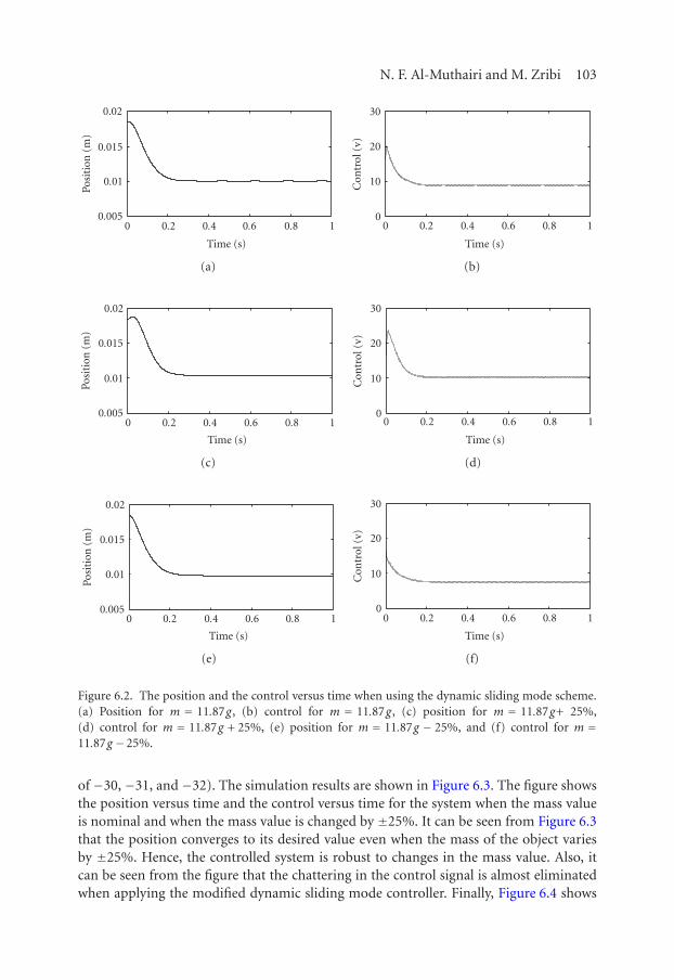
Third, the modified dynamic sliding mode controller (5.6), (5.7) is applied to themagnetic levitation system (2.3). The parameters of the controller are chosen such thatW2 = 100, c3 = 93, c2 = 2882, and c1 = 29760 (which correspond to closed-loop poles
N. F. Al-Muthairi and M. Zribi 103
0.02
0.015
0.01
0.0050 0.2 0.4 0.6 0.8 1
Time (s)
Posi
tion
(m)
(a)
30
20
10
00 0.2 0.4 0.6 0.8 1
Time (s)
Con
trol
(v)
(b)
0.02
0.015
0.01
0.0050 0.2 0.4 0.6 0.8 1
Time (s)
Posi
tion
(m)
(c)
30
20
10
00 0.2 0.4 0.6 0.8 1
Time (s)
Con
trol
(v)
(d)
0.02
0.015
0.01
0.0050 0.2 0.4 0.6 0.8 1
Time (s)
Posi
tion
(m)
(e)
30
20
10
00 0.2 0.4 0.6 0.8 1
Time (s)
Con
trol
(v)
(f)
Figure 6.2. The position and the control versus time when using the dynamic sliding mode scheme.(a) Position for m = 11.87g, (b) control for m = 11.87g, (c) position for m = 11.87g+ 25%,(d) control for m = 11.87g + 25%, (e) position for m = 11.87g − 25%, and (f) control for m =11.87g − 25%.
of −30, −31, and −32). The simulation results are shown in Figure 6.3. The figure showsthe position versus time and the control versus time for the system when the mass valueis nominal and when the mass value is changed by ±25%. It can be seen from Figure 6.3that the position converges to its desired value even when the mass of the object variesby ±25%. Hence, the controlled system is robust to changes in the mass value. Also, itcan be seen from the figure that the chattering in the control signal is almost eliminatedwhen applying the modified dynamic sliding mode controller. Finally, Figure 6.4 shows

104 Sliding mode control of a magnetic levitation system
0.02
0.015
0.01
0.0050 0.2 0.4 0.6 0.8 1
Time (s)
Posi
tion
(m)
(a)
30
20
10
00 0.2 0.4 0.6 0.8 1
Time (s)
Con
trol
(v)
(b)
0.02
0.015
0.01
0.0050 0.2 0.4 0.6 0.8 1
Time (s)
Posi
tion
(m)
(c)
30
20
10
00 0.2 0.4 0.6 0.8 1
Time (s)
Con
trol
(v)
(d)
0.02
0.015
0.01
0.0050 0.2 0.4 0.6 0.8 1
Time (s)
Posi
tion
(m)
(e)
30
20
10
00 0.2 0.4 0.6 0.8 1
Time (s)
Con
trol
(v)
(f)
Figure 6.3. The position and the control versus time when using the modified dynamic sliding modescheme. (a) Position for m = 11.87g, (b) control for m = 11.87g, (c) position for m = 11.87g+25%, (d) control for m = 11.87g + 25%, (e) position for m = 11.87g − 25%, and (f) control form= 11.87g − 25%.
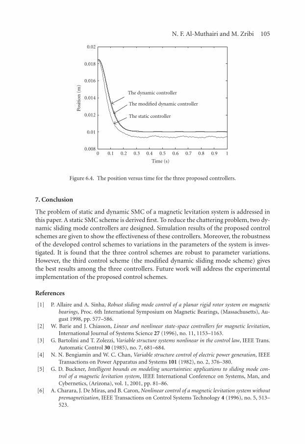
the position versus time for the three proposed controllers for the case when the massvalue is nominal.
Therefore, the simulation results indicate that the proposed control schemes work wellwhen applied to the magnetic levitation system. It can be concluded from the simulationsthat the static control scheme is somewhat robust to changes in the mass of the object.However, the dynamic controllers are very robust. It is also clear that the dynamic con-trollers greatly reduce the chattering.
N. F. Al-Muthairi and M. Zribi 105
0.02
0.018
0.016
0.014
0.012
0.01
0.0080 0.1 0.2 0.3 0.4 0.5 0.6 0.7 0.8 0.9 1
The modified dynamic controller
The dynamic controller
The static controller
Posi
tion
(m)
Time (s)
Figure 6.4. The position versus time for the three proposed controllers.
7. Conclusion
The problem of static and dynamic SMC of a magnetic levitation system is addressed inthis paper. A static SMC scheme is derived first. To reduce the chattering problem, two dy-namic sliding mode controllers are designed. Simulation results of the proposed controlschemes are given to show the effectiveness of these controllers. Moreover, the robustnessof the developed control schemes to variations in the parameters of the system is inves-tigated. It is found that the three control schemes are robust to parameter variations.However, the third control scheme (the modified dynamic sliding mode scheme) givesthe best results among the three controllers. Future work will address the experimentalimplementation of the proposed control schemes.
References
[1] P. Allaire and A. Sinha, Robust sliding mode control of a planar rigid rotor system on magneticbearings, Proc. 6th International Symposium on Magnetic Bearings, (Massachusetts), Au-gust 1998, pp. 577–586.
[2] W. Barie and J. Chiasson, Linear and nonlinear state-space controllers for magnetic levitation,International Journal of Systems Science 27 (1996), no. 11, 1153–1163.
[3] G. Bartolini and T. Zolezzi, Variable structure systems nonlinear in the control law, IEEE Trans.Automatic Control 30 (1985), no. 7, 681–684.
[4] N. N. Bengiamin and W. C. Chan, Variable structure control of electric power generation, IEEETransactions on Power Apparatus and Systems 101 (1982), no. 2, 376–380.
[5] G. D. Buckner, Intelligent bounds on modeling uncertainties: applications to sliding mode con-trol of a magnetic levitation system, IEEE International Conference on Systems, Man, andCybernetics, (Arizona), vol. 1, 2001, pp. 81–86.
[6] A. Charara, J. De Miras, and B. Caron, Nonlinear control of a magnetic levitation system withoutpremagnetization, IEEE Transactions on Control Systems Technology 4 (1996), no. 5, 513–523.

106 Sliding mode control of a magnetic levitation system
[7] M.-Y. Chen, C.-C. Wang, and L.-C. Fu, Adaptive sliding mode controller design of a dual-axis ma-glev positioning system, Proc. 2001 American Control Conference, (Virginia), vol. 5, 2001,pp. 3731–3736.
[8] D. Cho, Y. Kato, and D. Spilman, Sliding mode and classical controllers in magnetic levitationsystems, IEEE Control Systems Magazine 13 (1993), no. 1, 42–48.
[9] A. El Hajjaji and M. Ouladsine, Modeling and nonlinear control of magnetic levitation systems,IEEE Transactions on Industrial Electronics 48 (2001), no. 4, 831–838.
[10] O. El Rifai and K. Youcef-Toumi, Achievable performance and design trade-offs in magnetic levi-tation control, Proc. 5th International Workshop on Advanced Motion Control (AMC ’98),(Coimbra, Portugal), July 1998, pp. 586–591.
[11] M. R. Filho and C. J. Munaro, A design methodology of tracking controllers for magnetic levitationsystems, Proc. 2001 IEEE International Conference on Control Applications, (Mexico City),2001, pp. 47–51.
[12] M. Fujita, F. Matsumura, and K. Uchida, Experiments on the H∞ disturbance attenuation con-trol of a magnetic suspension system, Proc. 29th IEEE Conference on Decision and Control,(Hawaii), vol. 5, December 1990, pp. 2773–2778.
[13] M. Fujita, T. Namerikawa, F. Matsumura, and K. Uchida, µ-synthesis of an electromagnetic sus-pension system, IEEE Trans. Automatic Control 40 (1995), no. 3, 530–536.
[14] S. A. Green and K. C. Craig, Robust, design, nonlinear control of magnetic-levitation systems,Journal of Dynamics, Measurement, and Control 120 (1998), no. 4, 488–495.
[15] H. Hashimoto, H. Yamamoto, S. Yanagisawa, and F. Harashima, Brushless servo motor controlusing variable structure approach, IEEE Transactions on Industry Applications 24 (1988),no. 1, 160–170.
[16] D. M. M. Hassan and A. M. Mohamed, Variable structure control of a magnetic levitation system,Proc. 2001 American Control Conference, (Virginia), vol. 5, 2001, pp. 3725–3730.
[17] J. K. Hedrick and S. Gopalswamy, Nonlinear flight control design via sliding methods, Journal ofGuidance, Control and Dynamics 13 (1990), no. 5, 850–858.
[18] C.-M. Huang, J.-Y. Yen, and M.-S. Chen, Adaptive nonlinear control of repulsive maglev suspen-sion systems, Control Engineering Practice 8 (2000), no. 5, 1357–1367.
[19] J. Y. Hung, W. B. Gao, and J. C. Hung, Variable structure control: a survey, IEEE Transactionson Industrial Electronics 40 (1993), no. 1, 2–22.
[20] J. C. Kantor, Nonlinear sliding-mode controller and objective function for surge tanks, Internat. J.Control 50 (1989), no. 5, 2025–2047.
[21] Y. C. Kim and H. K. Kim, Gain scheduled control of magnetic suspension systems, Proc. AmericanControl Conference, (Maryland), vol. 3, July 1994, pp. 3127–3131.
[22] M. Lairi and G. Bloch, A neural network with minimal structure for maglev system modelingand control, Proc. 1999 IEEE International Symposium on Intelligent Control/IntelligentSystems and Semiotics, (Massachusetts), 1999, pp. 40–45.
[23] A. M. Mohamed, F. Matsumura, T. Namerikawa, and J.-H. Lee, Q-parametrization/µ-control ofan electromagnetic suspension system, Proc. 1997 IEEE International Conference on ControlApplications, (Connecticut), October 1997, pp. 604–608.
[24] K. Nonami and K. Nishina, Robust control of magnetic bearing systems by means of slidingmode control, Proc. 3rd International Symposium on Magnetic Bearings, (Virginia), 1992,pp. 221–226.
[25] A. Rundell, S. Drakunov, and R. DeCarlo, A sliding mode observer and controller for stabiliza-tion of rotational motion of a vertical shaft magnetic bearing, IEEE Transactions on ControlSystems Technology 4 (1996), no. 5, 598–608.
[26] H. Sira-Ramırez, On the sliding mode control of multivariable nonlinear systems, Internat. J.Control 64 (1996), no. 4, 745–765.

N. F. Al-Muthairi and M. Zribi 107
[27] H. Sira-Ramırez, S. Ahmad, and M. Zribi, Dynamical feedback control of robotic manipulatorswith joint flexibility, IEEE Transactions on Systems, Man and Cybernetics 22 (1992), no. 4,736–747.
[28] H. Sira-Ramırez, O. Llanes-Santiago, and N. Arrieta Fernandez, On the stabilization of non-linear systems via input-dependent sliding surfaces, Internat. J. Robust Nonlinear Control 6(1996), no. 8, 771–780.
[29] J. J. E. Slotine and W. Li, Applied Nonlinear Control, Prentice-Hall, New Jersey, 1991.[30] D. L. Trumper, M. Olson, and P. K. Subrahmanyan, Linearizing control of magnetic suspension
systems, IEEE Transactions on Control Systems Technology 5 (1997), no. 4, 427–438.[31] V. I. Utkin, Variable structure systems with sliding modes, IEEE Trans. Automatic Control 22
(1977), no. 2, 212–222.[32] , Sliding Modes and Their Application in Variable Structure Systems, Mir Publishers,
Moscow, 1978.[33] , Sliding Modes in Control and Optimization, Communications and Control Engineer-
ing Series, Springer-Verlag, Berlin, 1992.[34] , Variable structure systems and sliding mode—state of the art assessment, Variable Struc-
ture Control for Robotics and Aerospace Applications (K. D. Young, ed.), Elsevier, 1993,pp. 9–32.
[35] Z.-J. Yang and M. Tateishi, Robust nonlinear control of a magnetic levitation system via backstep-ping approach, Proc. 37th SICE Annual Conference (SICE ’98), (Chiba, Japan), July 1998,pp. 1063–1066.
[36] K. D. Young (ed.), Variable Structure Control for Robotics and Aerospace Applications, ElsevierScience, New York, 1993.
[37] K. D. Young, V. I. Utkin, and U. Ozguner, A control engineer’s guide to sliding mode control, IEEETransactions on Control Systems Technology 7 (1999), no. 3, 328–342.
[38] F. Zhang and K. Suyama, Nonlinear feedback control of magnetic levitating system by exact lin-earization approach, Proc. 4th IEEE Conference on Control Applications, (New York), Sep-tember 1995, pp. 267–268.
[39] F. Zhao, S. C. Loh, and J. A. May, Phase-space nonlinear control toolbox: the maglev experience,5th International Hybrid Systems Workshop, (Ind, September 1997) (P. Antsaklis, W. Kohn,M. Lemmon, A. Nerode, and S. Sastry, eds.), Lecture Notes in Computer Science, vol. 1567,Springer-Verlag, London, 1999, pp. 429–444.
[40] F. Zhao and R. Thornton, Automatic design of a Maglev controller in state space, Proc. of the 31stConference on Decision and Control, (Tucson, Ariz), December 1992, pp. 2562–2567.
[41] A. S. I. Zinober, Deterministic Control of Uncertain Systems, IEE Control Engineering Series,vol. 40, Peter Peregrinus, London, 1990.
[42] , Variable Structure and Lyapunov Control, Lecture Notes in Control and InformationSciences, vol. 193, Springer-Verlag, London, 1994.
N. F. Al-Muthairi: Department of Electrical Engineering, Kuwait University, P.O. Box 5969, Safat-13060, Kuwait
E-mail address: [email protected]
M. Zribi: Department of Electrical Engineering, Kuwait University, P.O. Box 5969, Safat-13060,Kuwait
E-mail address: [email protected]

Submit your manuscripts athttp://www.hindawi.com
Hindawi Publishing Corporationhttp://www.hindawi.com Volume 2014
MathematicsJournal of
Hindawi Publishing Corporationhttp://www.hindawi.com Volume 2014
Mathematical Problems in Engineering
Hindawi Publishing Corporationhttp://www.hindawi.com
Differential EquationsInternational Journal of
Volume 2014
Applied MathematicsJournal of
Hindawi Publishing Corporationhttp://www.hindawi.com Volume 2014
Probability and StatisticsHindawi Publishing Corporationhttp://www.hindawi.com Volume 2014
Journal of
Hindawi Publishing Corporationhttp://www.hindawi.com Volume 2014
Mathematical PhysicsAdvances in
Complex AnalysisJournal of
Hindawi Publishing Corporationhttp://www.hindawi.com Volume 2014
OptimizationJournal of
Hindawi Publishing Corporationhttp://www.hindawi.com Volume 2014
CombinatoricsHindawi Publishing Corporationhttp://www.hindawi.com Volume 2014
International Journal of
Hindawi Publishing Corporationhttp://www.hindawi.com Volume 2014
Operations ResearchAdvances in
Journal of
Hindawi Publishing Corporationhttp://www.hindawi.com Volume 2014
Function Spaces
Abstract and Applied AnalysisHindawi Publishing Corporationhttp://www.hindawi.com Volume 2014
International Journal of Mathematics and Mathematical Sciences
Hindawi Publishing Corporationhttp://www.hindawi.com Volume 2014
The Scientific World JournalHindawi Publishing Corporation http://www.hindawi.com Volume 2014
Hindawi Publishing Corporationhttp://www.hindawi.com Volume 2014
Algebra
Discrete Dynamics in Nature and Society
Hindawi Publishing Corporationhttp://www.hindawi.com Volume 2014
Hindawi Publishing Corporationhttp://www.hindawi.com Volume 2014
Decision SciencesAdvances in
Discrete MathematicsJournal of
Hindawi Publishing Corporationhttp://www.hindawi.com
Volume 2014 Hindawi Publishing Corporationhttp://www.hindawi.com Volume 2014
Stochastic AnalysisInternational Journal of