slc 500™ 32-channel digital i/o modules - ic … · slc 500™ 32-channel digital i/o modules 5...
TRANSCRIPT
Installation Instructions
SLC 500™ 32-Channel Digital I/O Modules
(Catalog Numbers 1746-IB32, -IV32, -OB32, -OB32E and -OV32)
Important User Information ........................................................... 2Hazardous Location Considerations .............................................. 3Environnements dangereux ........................................................... 3Overview ........................................................................................ 4Installation of Your I/O Module ..................................................... 4Specifications ................................................................................ 6Electronically Protected Module (1746-OB32E)............................. 8Installation of the Octal Label Kit (for PLC® Processors Only) ... 10Wiring Options for the I/O Module.............................................. 11Labeling for the 1492 Interface Module ...................................... 13Assembling the Wire Contacts .................................................... 15Wiring Diagrams.......................................................................... 16
Publication 1746-IN028A-EN-P - October 2003
2 SLC 500™ 32-Channel Digital I/O Modules
PLC is a registered trademark and SLC is a trademark of Rockwell Automation. SLC 500 is a trademark of Rockwell Automation.
Important User Information
Because of the variety of uses for the products described in this publication, those responsible for the application and use of these products must satisfy themselves that all necessary steps have been taken to assure that each application and use meets all performance and safety requirements, including any applicable laws, regulations, codes and standards. In no event will Rockwell Automation be responsible or liable for indirect or consequential damage resulting from the use or application of these products.
Any illustrations, charts, sample programs, and layout examples shown in this publication are intended solely for purposes of example. Since there are many variables and requirements associated with any particular installation, Rockwell Automation does not assume responsibility or liability (to include intellectual property liability) for actual use based upon the examples shown in this publication.
Allen-Bradley publication SGI-1.1, Safety Guidelines for the Application, Installation and Maintenance of Solid-State Control (available from your local Rockwell Automation office), describes some important differences between solid-state equipment and electromechanical devices that should be taken into consideration when applying products such as those described in this publication.
Reproduction of the contents of this copyrighted publication, in whole or part, without written permission of Rockwell Automation, is prohibited.
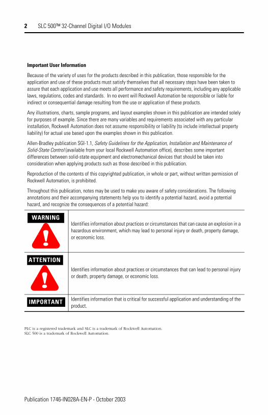
Throughout this publication, notes may be used to make you aware of safety considerations. The following annotations and their accompanying statements help you to identify a potential hazard, avoid a potential hazard, and recognize the consequences of a potential hazard:
!WARNING
Identifies information about practices or circumstances that can cause an explosion in a hazardous environment, which may lead to personal injury or death, property damage, or economic loss.
ATTENTION
!Identifies information about practices or circumstances that can lead to personal injury or death, property damage, or economic loss.
IMPORTANT Identifies information that is critical for successful application and understanding of the product.
Publication 1746-IN028A-EN-P - October 2003
SLC 500™ 32-Channel Digital I/O Modules 3
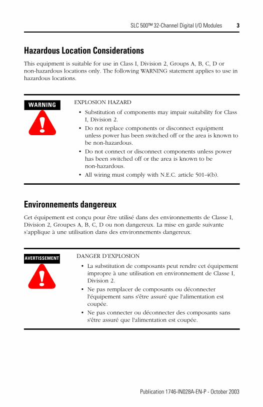
Hazardous Location ConsiderationsThis equipment is suitable for use in Class I, Division 2, Groups A, B, C, D or non-hazardous locations only. The following WARNING statement applies to use in hazardous locations.
Environnements dangereuxCet équipement est conçu pour être utilisé dans des environnements de Classe I, Division 2, Groupes A, B, C, D ou non dangereux. La mise en garde suivante s’applique à une utilisation dans des environnements dangereux.
!WARNING EXPLOSION HAZARD
• Substitution of components may impair suitability for Class I, Division 2.
• Do not replace components or disconnect equipment unless power has been switched off or the area is known to be non-hazardous.
• Do not connect or disconnect components unless power has been switched off or the area is known to be non-hazardous.
• All wiring must comply with N.E.C. article 501-4(b).
!AVERTISSEMENT DANGER D’EXPLOSION
• La substitution de composants peut rendre cet équipement impropre à une utilisation en environnement de Classe I, Division 2.
• Ne pas remplacer de composants ou déconnecter l'équipement sans s'être assuré que l'alimentation est coupée.
• Ne pas connecter ou déconnecter des composants sans s'être assuré que l'alimentation est coupée.
Publication 1746-IN028A-EN-P - October 2003
4 SLC 500™ 32-Channel Digital I/O Modules
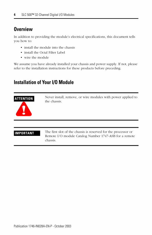
OverviewIn addition to providing the module’s electrical specifications, this document tells you how to:
• install the module into the chassis
• install the Octal Filter Label
• wire the module
We assume you have already installed your chassis and power supply. If not, please refer to the installation instructions for these products before preceding.
Installation of Your I/O Module
ATTENTION
!Never install, remove, or wire modules with power applied to the chassis.
IMPORTANT The first slot of the chassis is reserved for the processor or Remote I/O module Catalog Number 1747-ASB for a remote chassis.
Publication 1746-IN028A-EN-P - October 2003
SLC 500™ 32-Channel Digital I/O Modules 5
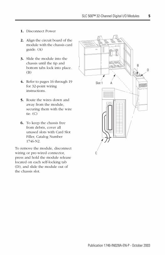
1. Disconnect Power
2. Align the circuit board of the module with the chassis card guide. (A)
3. Slide the module into the chassis until the tip and bottom tabs lock into place. (B)
4. Refer to pages 16 through 19 for 32-point wiring instructions.
5. Route the wires down and away from the module, securing them with the wire tie. (C)
6. To keep the chassis free from debris, cover all unused slots with Card Slot Filler, Catalog Number 1746-N2.
To remove the module, disconnect wiring or pre-wired connector, press and hold the module release located on each self-locking tab (D), and slide the module out of the chassis slot.
C
BD
ASlot 1
Publication 1746-IN028A-EN-P - October 2003
6 SLC 500™ 32-Channel Digital I/O Modules
Specifications
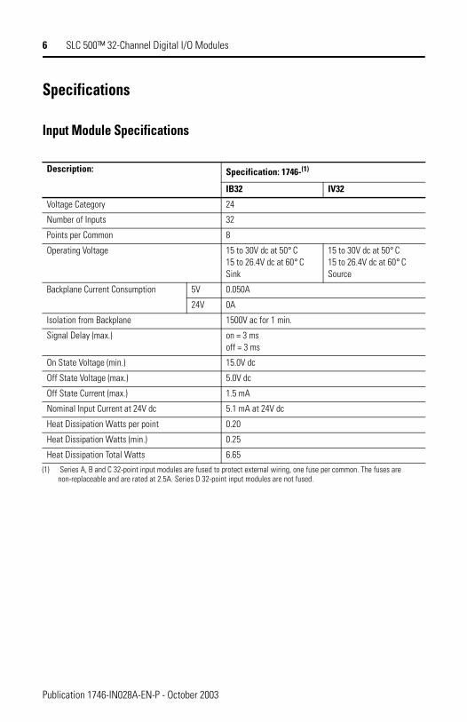
Input Module Specifications
Description: Specification: 1746-(1)
(1) Series A, B and C 32-point input modules are fused to protect external wiring, one fuse per common. The fuses are non-replaceable and are rated at 2.5A. Series D 32-point input modules are not fused.
IB32 IV32
Voltage Category 24
Number of Inputs 32
Points per Common 8
Operating Voltage 15 to 30V dc at 50° C 15 to 26.4V dc at 60° C Sink
15 to 30V dc at 50° C 15 to 26.4V dc at 60° C Source
Backplane Current Consumption 5V 0.050A
24V 0A
Isolation from Backplane 1500V ac for 1 min.
Signal Delay (max.) on = 3 msoff = 3 ms
On State Voltage (min.) 15.0V dc
Off State Voltage (max.) 5.0V dc
Off State Current (max.) 1.5 mA
Nominal Input Current at 24V dc 5.1 mA at 24V dc
Heat Dissipation Watts per point 0.20
Heat Dissipation Watts (min.) 0.25
Heat Dissipation Total Watts 6.65
Publication 1746-IN028A-EN-P - October 2003
SLC 500™ 32-Channel Digital I/O Modules 7
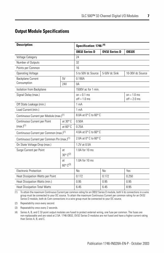
Output Module Specifications
Description: Specification: 1746-(4)
(4) Series A, B, and C 32-point output modules are fused to protect external wiring, one fuse per common. The fuses are non-replaceable and are rated at 2.5A. 1746-OB32, OV32 Series D modules are not fused and have a higher current rating than Series A, B, and C.
OB32 Series D OV32 Series D OB32E
Voltage Category 24
Number of Outputs 32
Points per Common 16
Operating Voltage 5 to 50V dc Source 5-50V dc Sink 10-30V dc Source
Backplane Current Consumption
5V 0.190A
24V 0A
Isolation from Backplane 1500V ac for 1 min.
Signal Delay (max.) on = 0.1 ms off = 1.0 ms
on = 1.0 ms off = 2.0 ms
Off State Leakage (min.) 1 mA
Load Current (min.) 1 mA
Continuous Current per Module (max.)(1)
(1) To attain the maximum Continuous Current per common rating for an OB32 Series D module, both V dc connections in a wire group must be connected to your DC source. To attain the maximum Continuous Current per common rating for an OV32 Series D module, both dc Com connections in a wire group must be connected to your DC source.
8.0A at 0° C to 60° C
Continuous Current per Point
(max.)(1)at 30° C 0.50A
at 60° C 0.25A
Continuous Current per Common (max.)(1) 4.0A at 0° C to 60° C
Continuous Current per Common Pin (max.)(1) 2.0A at 0° C to 60° C
On State Voltage Drop (max.) 1.2V at 0.5A
Surge Current per Point at
30° C(2)
(2) Repeatability once every second.
1.0A for 10 ms
at
60° C(3)
(3) Repeatability once every 2 seconds.
1.0A for 10 ms
Electronic Protection No No Yes
Heat Dissipation Watts per Point 0.172 0.172 0.250
Heat Dissipation Watts (min.) 0.95 0.95 0.95
Heat Dissipation Total Watts 6.45 6.45 8.95
Publication 1746-IN028A-EN-P - October 2003
8 SLC 500™ 32-Channel Digital I/O Modules
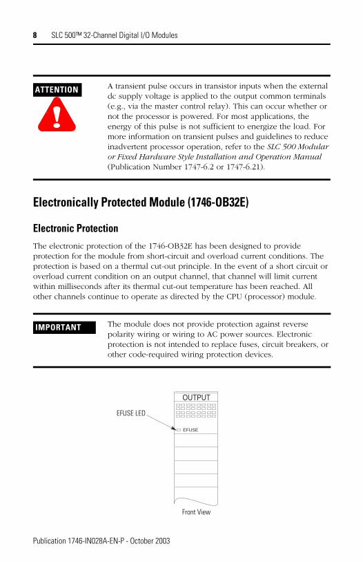
Electronically Protected Module (1746-OB32E)
Electronic ProtectionThe electronic protection of the 1746-OB32E has been designed to provide protection for the module from short-circuit and overload current conditions. The protection is based on a thermal cut-out principle. In the event of a short circuit or overload current condition on an output channel, that channel will limit current within milliseconds after its thermal cut-out temperature has been reached. All other channels continue to operate as directed by the CPU (processor) module.
ATTENTION
!A transient pulse occurs in transistor inputs when the external dc supply voltage is applied to the output common terminals (e.g., via the master control relay). This can occur whether or not the processor is powered. For most applications, the energy of this pulse is not sufficient to energize the load. For more information on transient pulses and guidelines to reduce inadvertent processor operation, refer to the SLC 500 Modular or Fixed Hardware Style Installation and Operation Manual (Publication Number 1747-6.2 or 1747-6.21).
IMPORTANT The module does not provide protection against reverse polarity wiring or wiring to AC power sources. Electronic protection is not intended to replace fuses, circuit breakers, or other code-required wiring protection devices.
OUTPUT
EFUSE
EFUSE LED
Front View
Publication 1746-IN028A-EN-P - October 2003
SLC 500™ 32-Channel Digital I/O Modules 9
Auto Reset Operation
Short Circuit/Overload Current Diagnostics
If a short circuit or overload current condition occurs on an output channel:
1. The E-Fuse LED will illuminate provided that power is applied to the module. (power required: 5V dc via backplane and load power via an external supply)
2. All other channels continue to operate as directed by the CPU (processor) module.
Recovery From Channel Shutdown
1. Remove the SLC 500 system power and correct the conditions causing the short circuit or overload current condition.
2. Restore the SLC 500 system power. The module automatically resets and resumes control of the output channel and associated load.
IMPORTANT The 1746-OB32E performs auto-reset under overload conditions. When an output channel overload occurs as described above, that channel limits current within milliseconds after its thermal cut-out temperature has been reached. While in current limit, the output channel can cool below the thermal cut-out temperature, allowing the module to auto-reset and resume control of the output channel as directed by the processor until the thermal cut-out temperature is again reached.
Removing power from an overloaded output channel would also allow the output channel to cool below the thermal cut-out temperature allowing auto-reset to occur when power is restored. The output channel would operate as directed by the processor until the thermal cut-out temperature is again reached.
To avoid auto-reset of an output channel under overload conditions, an external mechanical fuse can be used to open the circuit when overloaded.
Publication 1746-IN028A-EN-P - October 2003
10 SLC 500™ 32-Channel Digital I/O Modules
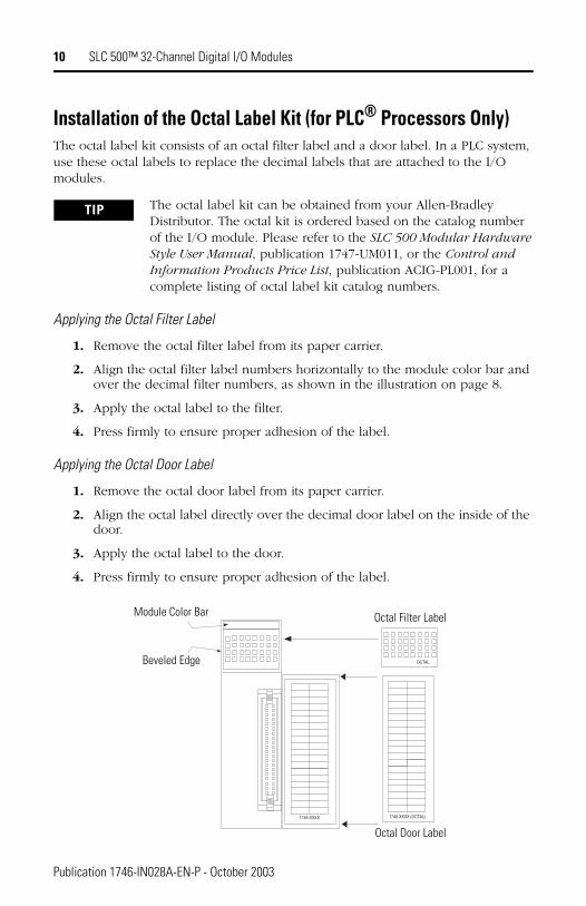
Installation of the Octal Label Kit (for PLC® Processors Only)The octal label kit consists of an octal filter label and a door label. In a PLC system, use these octal labels to replace the decimal labels that are attached to the I/O modules.
Applying the Octal Filter Label
1. Remove the octal filter label from its paper carrier.
2. Align the octal filter label numbers horizontally to the module color bar and over the decimal filter numbers, as shown in the illustration on page 8.
3. Apply the octal label to the filter.
4. Press firmly to ensure proper adhesion of the label.
Applying the Octal Door Label
1. Remove the octal door label from its paper carrier.
2. Align the octal label directly over the decimal door label on the inside of the door.
3. Apply the octal label to the door.
4. Press firmly to ensure proper adhesion of the label.
TIP The octal label kit can be obtained from your Allen-Bradley Distributor. The octal kit is ordered based on the catalog number of the I/O module. Please refer to the SLC 500 Modular Hardware Style User Manual, publication 1747-UM011, or the Control and Information Products Price List, publication ACIG-PL001, for a complete listing of octal label kit catalog numbers.
1746-XXXX 1746-XXXX (OCTAL)
OCTAL
Module Color Bar
Beveled Edge
Octal Filter Label
Octal Door Label
Publication 1746-IN028A-EN-P - October 2003
SLC 500™ 32-Channel Digital I/O Modules 11
Wiring Options for the I/O ModuleIncluded with your 32-point I/O module is a keyed 40-pin female connector and crimp type pins. These components allow you to wire I/O devices to the module using a 40-conductor cable or individual wires. The wiring diagrams on pages 16 through 19 show the I/O terminations of the connector for your specific module. Refer to page 15 for connector/pin assembly instructions. When assembled, align the female connector over the modules male header using the keying slot as a guide. Firmly lock them together with the upper and lower retaining arms. 1492 pre-wired cables and interface modules can be used for connecting external I/O.
There are two options for wiring the 32-point I/O module.
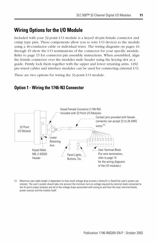
Option 1 - Wiring the 1746-N3 Connector
(1) Maximum user cable length is dependent on how much voltage drop (current x (ohms/ft.) x (feet)) the user’s system can tolerate. The user’s system should take into account the minimum turn-on voltage required by external loads connected to the 32-point output modules and all of the voltage drops associated with wiring to and from the load, terminal blocks, power sources and the module itself.
Keyed Female Connector (1746-N3)Included with 32-Point I/O Modules
Contact pins provided with female connector can accept 22 to 26 AWG
wires.(1)
User Terminal Block(For wire termination,refer to page 14for the wiring diagramsof the I/O modules.)
Panel Lights,Buttons, Etc.
LowerRetainingArm
Keyed MaleMIL-C-83503Header
32 PointI/O Module
Publication 1746-IN028A-EN-P - October 2003
12 SLC 500™ 32-Channel Digital I/O Modules
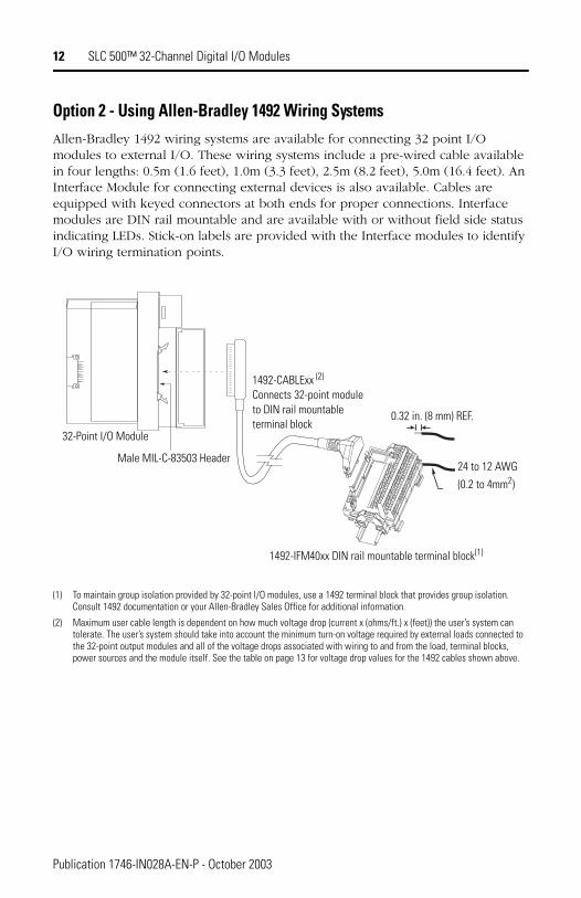
Option 2 - Using Allen-Bradley 1492 Wiring SystemsAllen-Bradley 1492 wiring systems are available for connecting 32 point I/O modules to external I/O. These wiring systems include a pre-wired cable available in four lengths: 0.5m (1.6 feet), 1.0m (3.3 feet), 2.5m (8.2 feet), 5.0m (16.4 feet). An Interface Module for connecting external devices is also available. Cables are equipped with keyed connectors at both ends for proper connections. Interface modules are DIN rail mountable and are available with or without field side status indicating LEDs. Stick-on labels are provided with the Interface modules to identify I/O wiring termination points.
(1) To maintain group isolation provided by 32-point I/O modules, use a 1492 terminal block that provides group isolation. Consult 1492 documentation or your Allen-Bradley Sales Office for additional information.
(2) Maximum user cable length is dependent on how much voltage drop (current x (ohms/ft.) x (feet)) the user’s system can tolerate. The user’s system should take into account the minimum turn-on voltage required by external loads connected to the 32-point output modules and all of the voltage drops associated with wiring to and from the load, terminal blocks, power sources and the module itself. See the table on page 13 for voltage drop values for the 1492 cables shown above.
32-Point I/O Module
Male MIL-C-83503 Header
1492-CABLExx (2)
Connects 32-point module to DIN rail mountable terminal block
0.32 in. (8 mm) REF.
1492-IFM40xx DIN rail mountable terminal block(1)
24 to 12 AWG
(0.2 to 4mm2)
Publication 1746-IN028A-EN-P - October 2003
SLC 500™ 32-Channel Digital I/O Modules 13
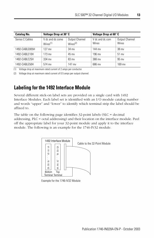
Labeling for the 1492 Interface ModuleSeveral different stick-on label sets are provided on a single card with 1492 Interface Modules. Each label set is identified with an I/O module catalog number and words “upper” and “lower” to identify which terminal strip the label should be affixed to.
The table on the following page identifies 32-point labels (SLC = decimal addressing, PLC = octal addressing) and their location on the interface module. Peel off the appropriate label for your 32-point module and apply it to the interface module. The following is an example for the 1746-IV32 module.
Catalog No. Voltage Drop at 30° C Voltage Drop at 60° C
Series C Cables V dc and dc come
Wires(1)
(1) Voltage drop at maximum rated current of 2 amps per conductor.
Output Channel
Wires(2)
(2) Voltage drop at maximum rated current of 0.5 amps per output channel.
V dc and dc com Wires
Output Channel Wires
1492-CABLE005H 127 mv 34 mv 144 mv 38 mv
1492-CABLE10H 173 mv 45 mv 196 mv 51 mv
1492-CABLE25H 334 mv 83 mv 388 mv 95 mv
1492-CABLE50H 574 mv 147 mv 686 mv 169 mv
1492 Interface Module
BottomTerminal
TopTerminal
V1 V1 01 15 V2 V2
V3 V3 16 31 V4 V4
Cable to the 32-Point Module
Example for the 1746-IV32 Module
Publication 1746-IN028A-EN-P - October 2003
14 SLC 500™ 32-Channel Digital I/O Modules
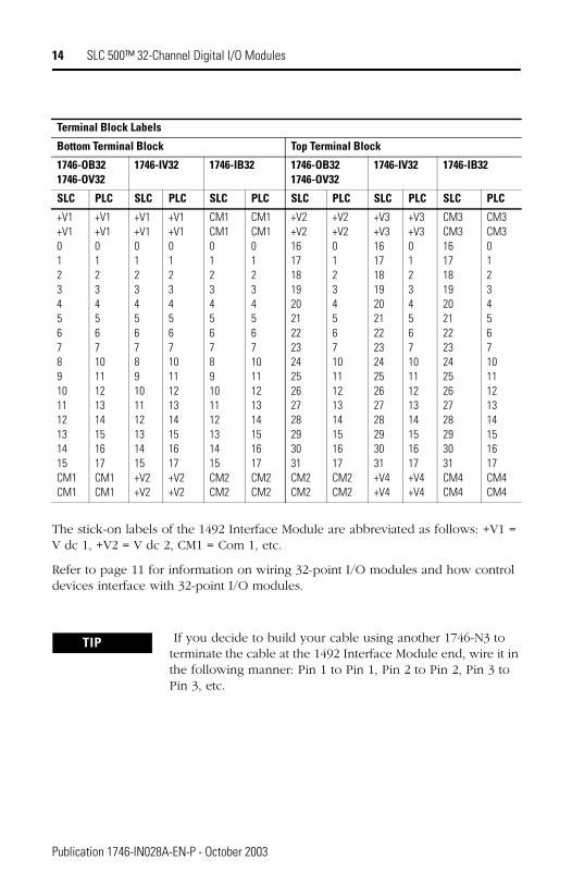
The stick-on labels of the 1492 Interface Module are abbreviated as follows: +V1 = V dc 1, +V2 = V dc 2, CM1 = Com 1, etc.
Refer to page 11 for information on wiring 32-point I/O modules and how control devices interface with 32-point I/O modules.
Terminal Block Labels
Bottom Terminal Block Top Terminal Block
1746-OB321746-OV32
1746-IV32 1746-IB32 1746-OB321746-OV32
1746-IV32 1746-IB32
SLC PLC SLC PLC SLC PLC SLC PLC SLC PLC SLC PLC
+V1+V10123456789101112131415CM1CM1
+V1+V1012345671011121314151617CM1CM1
+V1+V10123456789101112131415+V2+V2
+V1+V1012345671011121314151617+V2+V2
CM1CM10123456789101112131415CM2CM2
CM1CM1012345671011121314151617CM2CM2
+V2+V216171819202122232425262728293031CM2CM2
+V2+V2012345671011121314151617CM2CM2
+V3+V316171819202122232425262728293031+V4+V4
+V3+V3012345671011121314151617+V4+V4
CM3CM316171819202122232425262728293031CM4CM4
CM3CM3012345671011121314151617CM4CM4
TIP If you decide to build your cable using another 1746-N3 to terminate the cable at the 1492 Interface Module end, wire it in the following manner: Pin 1 to Pin 1, Pin 2 to Pin 2, Pin 3 to Pin 3, etc.
Publication 1746-IN028A-EN-P - October 2003
SLC 500™ 32-Channel Digital I/O Modules 15
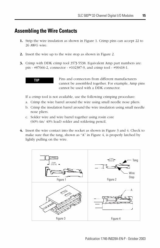
Assembling the Wire Contacts
1. Strip the wire insulation as shown in Figure 1. Crimp pins can accept 22 to 26 AWG wire.
2. Insert the wire up to the wire stop as shown in Figure 2.
3. Crimp with DDK crimp tool 357J-5538. Equivalent Amp part numbers are: pin - #87666-2, connector - #102387-9, and crimp tool - #90418-1.
If a crimp tool is not available, use the following crimping procedure:
a. Crimp the wire barrel around the wire using small needle nose pliers.
b. Crimp the insulation barrel around the wire insulation using small needle nose pliers.
c. Solder wire and wire barrel together using rosin core (60% tin/ 40% lead) solder and soldering pencil.
4. Insert the wire contact into the socket as shown in Figure 3 and 4. Check to make sure that the tang, shown as “A” in Figure 4, is properly latched by lightly pulling on the wire.
TIP Pins and connectors from different manufacturers cannot be assembled together. For example, Amp pins cannot be used with a DDK connector.
4 mm(5/32 in)
4 mm(5/32 in)
A
4 mm(5/32 in)
4 mm(5/32 in)
A
Figure 1 Figure 2
Figure 3 Figure 4
Tang
Wire Stop
Publication 1746-IN028A-EN-P - October 2003
16 SLC 500™ 32-Channel Digital I/O Modules
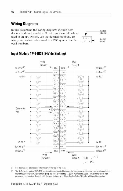
Wiring DiagramsIn this document, the wiring diagrams include both decimal and octal numbers. To wire your module when used in an SLC system, use the decimal numbers. To wire your module when used in a PLC system, use the octal numbers.
Input Module 1746-IB32 (24V dc Sinking)
(1) See decimal and octal coding information at the top of the page.
(2) The dc Com pins on the 1746-IB32 input module are isolated between the four groups and the two com pins in each group are connected internally. To maintain group isolation provided by 32-point I/O modules, use a 1492 terminal block that provides group isolation. Consult 1492 documentation or your Allen-Bradley Sales Office for additional information.
IN 14
16For PLC(octal)
For SLC(decimal)
IN 0
0
IN 1 1
IN 2 2
IN 3 3
IN 4 4
IN 5 5
IN 6
6IN 7
7IN 8
10IN 9
11IN 10
12IN 11
13IN 12
14IN 13
15IN 14
16IN 15
17
IN 16
IN 17
IN 18
IN 19
IN 20
IN 21
IN 22
IN 23
IN 24
IN 25
IN 26
IN 27
IN 28
IN 29
IN 30
IN 31
COM 1
COM 1 COM 3
COM 3
COM 2
COM 2
COM 4
COM 4
0
1
2
3
4
5
6
7
10
11
12
13
14
15
16
17
SLC
PLC
dc Com 1(2)
dc Com 1(2)
+V dc 1
WireGroup 1
WireGroup 3
dc Com 3(2)
dc Com 3(2)
+V dc 3
dc Com 2(2)
dc Com 2(2)
+V dc 2
dc Com 4(2)
dc Com 4(2)
+V dc 4
(1)
ConnectorKey
Wire Group 2
Wire Group 4
Publication 1746-IN028A-EN-P - October 2003
SLC 500™ 32-Channel Digital I/O Modules 17
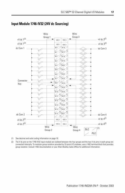
Input Module 1746-IV32 (24V dc Sourcing)
(1) See decimal and octal coding information on page 16.
(2) The V dc pins on the 1746-IV32 input module are isolated between the four groups and the two V dc pins in each group are connected internally. To maintain group isolation provided by 32-point I/O modules, use a 1492 terminal block that provides group isolation. Consult 1492 documentation or your Allen-Bradley Sales Office for additional information.
IN 0
0IN 1
1IN 2
2IN 3
3IN 4
4IN 5
5IN 6
6IN 7
7IN 8
10IN 9
11IN 10
12IN 11
13IN 12
14IN 13
15IN 14
16IN 15
17
IN 16
IN 17
IN 18
IN 19
IN 20
IN 21
IN 22
IN 23
IN 24
IN 25
IN 26
IN 27
IN 28
IN 29
IN 30
IN 31
VDC 1
0
1
2
3
4
5
6
7
10
11
12
13
14
15
16
17
VDC 1
VDC 3
VDC 3
VDC 2 VDC 4
VDC 2 VDC 4
SLC
PLC
Wire Group 1
Wire Group 3
+V dc 3(2)
+V dc 3(2)
dc Com 3
dc Com 4
+V dc 4(2)
+V dc 4(2)
+V dc 1(2)
+V dc 1(2)
dc Com 1
ConnectorKey
Wire Group 2
Wire Group 4
dc Com 2
+V dc 2(2)
+V dc 2(2)
(1)
Publication 1746-IN028A-EN-P - October 2003
18 SLC 500™ 32-Channel Digital I/O Modules
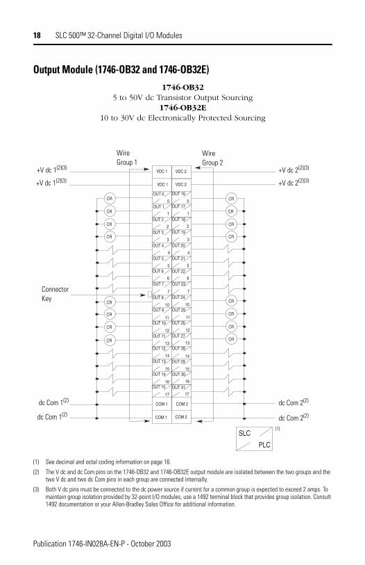
Output Module (1746-OB32 and 1746-OB32E)1746-OB32
5 to 50V dc Transistor Output Sourcing1746-OB32E
10 to 30V dc Electronically Protected Sourcing
(1) See decimal and octal coding information on page 16.
(2) The V dc and dc Com pins on the 1746-OB32 and 1746-OB32E output module are isolated between the two groups and the two V dc and two dc Com pins in each group are connected internally.
(3) Both V dc pins must be connected to the dc power source if current for a common group is expected to exceed 2 amps. To maintain group isolation provided by 32-point I/O modules, use a 1492 terminal block that provides group isolation. Consult 1492 documentation or your Allen-Bradley Sales Office for additional information.
OUT 0
0OUT 1
1OUT 2
2OUT 3
3OUT 4
4OUT 5
5OUT 6
6OUT 7
7OUT 8
10OUT 9
11OUT 10
12OUT 11
13OUT 12
14OUT 13
15OUT 14
16OUT 15
17
OUT 16
OUT 17
OUT 18
OUT 19
OUT 20
OUT 21
OUT 22
OUT 23
OUT 24
OUT 25
OUT 26
OUT 27
OUT 28
OUT 29
OUT 30
OUT 31
VDC 1
0
1
2
3
4
5
6
7
10
11
12
13
14
15
16
17
VDC 1
VDC 2
VDC 2
COM 2
COM 2COM 1
COM 1
CR
CR
CR
CR
CR
CR
CR
CR
CR
CR
CR
CR
CR
CR
CR
CR
SLC
PLC
WireGroup 1
WireGroup 2
+V dc 2(2)(3)
+V dc 2(2)(3)+V dc 1(2)(3)
+V dc 1(2)(3)
ConnectorKey
dc Com 2(2)
dc Com 2(2)
dc Com 1(2)
dc Com 1(2)
(1)
Publication 1746-IN028A-EN-P - October 2003
SLC 500™ 32-Channel Digital I/O Modules 19
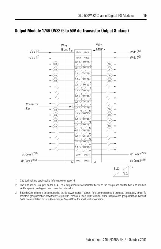
Output Module 1746-OV32 (5 to 50V dc Transistor Output Sinking)
(1) See decimal and octal coding information on page 16.
(2) The V dc and dc Com pins on the 1746-OV32 output module are isolated between the two groups and the two V dc and two dc Com pins in each group are connected internally.
(3) Both dc Com pins must be connected to the dc power source if current for a common group is expected to exceed 2 amps. To maintain group isolation provided by 32-point I/O modules, use a 1492 terminal block that provides group isolation. Consult 1492 documentation or your Allen-Bradley Sales Office for additional information.
OUT 0
0OUT 1
1OUT 2
2OUT 3
3OUT 4
4OUT 5
5OUT 6
6OUT 7
7OUT 8
10OUT 9
11OUT 10
12OUT 11
13OUT 12
14OUT 13
15OUT 14
16OUT 15
17
OUT 16
OUT 17
OUT 18
OUT 19
OUT 20
OUT 21
OUT 22
OUT 23
OUT 24
OUT 25
OUT 26
OUT 27
OUT 28
OUT 29
OUT 30
OUT 31
VDC 1
0
1
2
3
4
5
6
7
10
11
12
13
14
15
16
17
VDC 1
VDC 2
VDC 2
COM 2
COM 2COM 1
COM 1
CR
CR
CR
CR
CR
CR
CR
CR
CR
CR
CR
CR
CR
CR
CR
CR
SLC
PLC
WireGroup 1
WireGroup 2
+V dc 2(2)
+V dc 2(2)
dc Com 2(2)(3)
dc Com 2(2)(3)
(1)
dc Com 1(2)(3)
dc Com 1(2)(3)
ConnectorKey
+V dc 1(2)
+V dc 1(2)
Publication 1746-IN028A-EN-P - October 2003
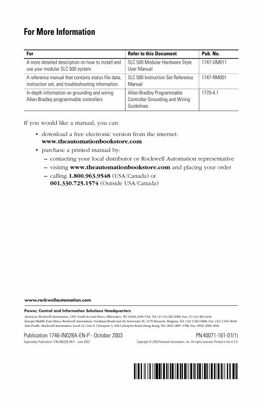
For More Information
If you would like a manual, you can:
• download a free electronic version from the internet: www.theautomationbookstore.com
• purchase a printed manual by:
– contacting your local distributor or Rockwell Automation representative
– visiting www.theautomationbookstore.com and placing your order
– calling 1.800.963.9548 (USA/Canada) or 001.330.725.1574 (Outside USA/Canada)
For Refer to this Document Pub. No.
A more detailed description on how to install and use your modular SLC 500 system.
SLC 500 Modular Hardware Style User Manual
1747-UM011
A reference manual that contains status file data, instruction set, and troubleshooting information.
SLC 500 Instruction Set Reference Manual
1747-RM001
In-depth information on grounding and wiring Allen-Bradley programmable controllers
Allen-Bradley Programmable Controller Grounding and Wiring Guidelines
1770-4.1
Publication 1746-IN028A-EN-P - October 2003 PN 40071-161-01(1) Supersedes Publication 1746-IN023B-EN-P - June 2002 Copyright © 2003 Rockwell Automation, Inc. All rights reserved. Printed in the U.S.A.
´H'¶1-161-011$¨