sl operator's manual - r129motoring.com - home · automatic climate control 22 inside rear...
TRANSCRIPT

1
Mercedes-Benz
SL Operator's Manual320 SL500 SL600 SL

2
Product information
Kindly observe the following in your own best interest:We recommend using Mercedes-Benz original parts as well as conversion parts and accessories explicitly approved by us foryour vehicle model. We have tested these parts to determine their reliability, safety and their special suitability for Mercedes-Benz vehicles.We are unable to make an assessment for other products and therefore cannot be held responsible for them, even if in individual casesan official approval or authorization by governmental or other agencies should exist. Use of such parts and accessories couldadversely affect the safety, performance or reliability of your vehicle. Please do not use them. Mercedes-Benz original parts as well asconversion parts and accessories approved by us are available at your authorized Mercedes-Benz Center where you will receivecomprehensive information, also on permissible technical modifications, and where proper installation will be performed.
Our company and staff congratulate you on the purchase of your new Mercedes-Benz.Your selection of our product is a demonstration of your trust in our company name. Further, it exemplifies your desire to own anautomobile that will be as easy as possible to operate and provide years of service.Your Mercedes-Benz represents the efforts of many skilled engineers and craftsmen. To ensure your pleasure of ownership, andfor your safety and that of your passengers, we ask you to make a small investment of your time:
• Please read this manual carefully before putting it aside. Then return it to your vehicle where it will be handy foryour reference.
• Please abide by the recommendations contained in this manual. They are designed to acquaint you with theoperation of your Mercedes-Benz.
• Please abide by the warnings and cautions contained in this manual. They are designed to help improve the safetyof the vehicle operator and occupants.
We extend our best wishes for many miles of safe, pleasurable driving.
DaimlerChrysler AG

3
Operator's manual
This Operator's Manual contains a great deal of useful information. We urge you to read it carefully and familiarize yourself with thevehicle before driving.For your own safety and longer service life of the vehicle, we urge you to follow the instructions and warnings contained in thismanual. Ignoring them could result in damage to the vehicle or personal injury to you or others. Vehicle damage caused by failure tofollow instructions is not covered by the Mercedes-Benz Limited Warranty.Your vehicle may have some or all of the equipment described in this manual. Therefore, you may find explanations for optionalequipment not installed in your vehicle. If you have any questions about the operation of any equipment, your authorized Mercedes-Benz Center will be glad to demonstrate the proper procedures.Service and warranty informationThe Service and Warranty Information Booklet contains detailed information about the warranties covering your Mercedes-Benz,including:
• New Car Limited Warranty,• Emission System Warranty,• Emission Performance Warranty,• California, Massachusetts, and Vermont Emission Control System Warranty
(California, Massachusetts, and Vermont only),• State Warranty Enforcement Laws (Lemon Laws).

4
Important notice for California retail buyers of Mercedes-Benz automobiles
Under California law you may be entitled to a replacement of your vehicle or a refund of the purchase price, if Mercedes-BenzUSA,LLC or its authorized Mercedes-Benz Center fails to conform the vehicle to its express warranties after a reasonable number ofrepair attempts during the period of one year or 12 000 miles from original delivery of the vehicle. A reasonable number of repairattempts is presumed for a retail buyer (1) if the vehicle is out of service by reason of repair of substantial nonconformities for acumulative total of more than 30 calendar days or (2) the same substantial non-conformity has been subject to repair four or moretimes and you have at least once directly notified us in writing of the need to repair the non-conformity and have given us anopportunity to perform the repair ourselves. Notifications should be sent to the nearest Mercedes-Benz Regional Office listedin the Service and Warranty Information Booklet.Maintenance
The Service Booklet describes all the necessary maintenance work which should be performed at regular intervals.Always have the Service Booklet with you when you take the vehicle to your authorized Mercedes-Benz Center for service.The service advisor will record each service in the booklet for you.
Roadside assistance
The Mercedes-Benz Roadside Assistance Program provides factory trained technical help in the event of a breakdown. Calls to thetoll-free Roadside Assistance number:1-800-FOR-MERCedes (in the USA)1-800-387-0100 (in Canada)will be answered by Mercedes-Benz Client Assistance Representatives 24 hours a day, 365 days a year.For additional information refer to the Mercedes-Benz Roadside Assistance Program brochure in your glove box.

5
Change of address or ownership
If you change your address, be sure to send in the "Change of Address Notice" found in the Service and Warranty InformationBooklet, or simply call the Mercedes-Benz Client Assistance Center (in the USA) at 1-800-FOR-MERCedes, or Customer Service (inCanada) at 1-800-387-0100. It is in your own interest that we can contact you should the need arise.If you sell your Mercedes, please leave all literature with the vehicle to make it available to the next operator.If you bought this vehicle used, be sure to send in the "Notice of Purchase of Used Car" found in the Service and WarrantyInformation Booklet, or call the Mercedes-Benz Client Assistance Center (in the USA)at 1-800-FOR-MERCedes, or Customer Service (in Canada) at 1-800-387-0100.
Operating your vehicle outside the USA or Canada
If you plan to operate your vehicle in foreign countries, please be aware that:• Service facilities or replacement parts may not be readily available,• unleaded gasoline for vehicles with catalytic converters may not be available; the use of leaded fuels will damage the catalysts,• gasoline may have a considerably lower octane rating, and improper fuel can cause engine damage.Certain Mercedes-Benz models are available for delivery in Europe under our European Delivery Program.For details, consult your authorized Mercedes-Benz Center or write to:
In the USA: In Canada:Mercedes-Benz USA, Mercedes-Benz Canada, Inc.LLC European Delivery Department European Delivery DepartmentOne Mercedes Drive 849 Eglinton Avenue EastMontvale, NI 07645-0350 Toronto, Ontario M4G 2L5

6
We continuously strive to improve our product, and ask for your understanding that we reserve the right to make changes in designand equipment. Therefore, information, illustrations and descriptions in this Operator's Manual might differ from your vehicle.Optional equipment is also described in this manual, including operating instructions wherever necessary. Since they are special-orderitems, the descriptions and illustrations herein may vary slightly from the actual equipment of your vehicle.If there are any equipment details that are not shown or described in this Operator's Manual, your authorized Mercedes-Benz Center will be glad to inform you of correct care and operating procedures.The Operator's Manual and Service Booklet are important documents and should be kept with the vehicle.

7
The First 1000 Miles (1500km)
The more cautiously you treat yourvehicle during the break-in period, themore satisfied you will be with itsperformance later on. Therefore, driveyour vehicle during the first 1000 miles(1500 km) at moderate vehicle andengine speeds.
During this period, avoid heavy loads(full throttle driving) and excessiveengine speeds.
Avoid accelerating by kickdown. It isnot recommended to brake the vehicleby manually shifting to a lower gear.We recommend to select positions "3","2" or "1" only at moderate speeds (forhill driving).
After 1000 miles (1500 km) speedsmay be gradually increased to thepermissible maximum.
Check Regularly and Before a LongTrip
See Index
Maintenance
We strongly recommend that you haveyour vehicle serviced by yourauthorized Mercedes-Benz dealer, inaccordance with the MaintenanceBooklet.
Failure to have the vehicle maintainedin accordance with the MaintenanceBooklet may result in vehicle damagenot covered by the Mercedes-Benz.Limited Warranty.
Radio Transmitters
Warning!
Never operate radio transmittersequipped with a built-in or attachedantenna (i.e. without the telephoneconnected to an external antenna)from inside the vehicle while theengine is running. Doing so couldlead to a malfunction of the vehicle'selectronic system, possibly resultingin an accident and personal injury.
Radio transmitters, such as a portabletelephone or a citizens band unit,should only be used inside the vehicleif they are connected to an antenna thatis installed on the outside of thevehicle.Refer to the radio transmitter operationinstructions regarding use of anexternal antenna.

8
Introduction Central locking switch 32 Storage Compartments (EyeglassesTrunk 31 compartment) in dashboard 59
Product information 2 Power windows 32 Door pockets 60Operator's manual 4 Interior Central locking system 33 Rear Storage Compartments 60Consumer Information 149 Antitheft Alarm System 34 Ashtray 61Problems with your vehicle 150 Power seat 35 Lighter 61Reporting Safety Defects 151 Backrest 37 Interior Lighting 62Index 158 Multicontour seat 38 Roll Bar 63
Heated Seats 39 Sunshade 65Instruments and controls Armrest 40 Panorama roof (Hardtop) 66
Adjusting steering column 40 Soft top 70Instruments and controls 10 Seat belts and Supplemental restraint Wind Screen 73Instrument Cluster 12 system (SRS) 41 Cellular telephone 75Indicator Lamp Symbols 13 Emergency tensioning retractor (ETR) 45 Antenna 75Catalytic Converter 14 Airbags 46Starting and Turning Off the Engine 15 Child restraint 50 DrivingDriving Instructions 16 Steering Lock 51
Combination Switch 52 Drinking and Driving 78Operation Exterior Lamp Switch 54 Parking Brake 78
Exterior rear view mirrors 55 Driving off 78Automatic Climate Control 22 Inside rear view mirror 55 Automatic Transmission 79Basic settings – automatic mode 23 Night security illumination 56 Cruise Control 83Defogging windows 24 Sun Visors 56 Charge Indicator Lamp 85Defrosting 24 Vanity mirrors 56 Engine oil pressure Gauge 85Rear window defroster 24 Instrument Lamps 57 Low Engine Oil Level Warning Lamp 85Air recirculation 25 Display illumination 57 Engine Oil Consumption 86Car Keys 26 Trip Odometer 57 Fuel Consumption Gauge 86Start lock out 27 Clock 57 Tachometer 86Infrared Remote Control 27 Garage door opener 58 Fuel reserve warning lamp 87Central locking system 32 Outside temperature indicator 87Doors 30Trunk 33

9
Coolant temperature gauge 87 Checking engine oil level 104 Technical Data. Fuels, Coolants,Low engine coolant level Checking Automatic Lubricants etc. Consumer
warning lamp 88 Transmission Fluid Level 105 InformationLow windshield and Trunk Lamp 105
Headlamp washer system First Aid Kit 106 Identification Plates 136Fluid level warning lamp 88 Stowing things in vehicle 106 Vehicle Data Card 137
Roll Bar Warning Lamp 89 Vehicle Tools 106 Warranty Coverage 137Seat Belt and Backrest Lock Spare Wheel 106 Technical Data SL 320 138
Warning Lamp 89 Vehicle Jack 107 SL 500 140Exterior Lamp Failure Indicator Lamp 89 Wheels 107 SL 600 142Brake Pad Wear Indicator Lamp 90 Changing Wheels 109 Fuels, Coolants, Lubricants etc. 144Brake Warning Lamp 90 Tire inflation Pressure 112 Capacities 144ABS (Antilock Brake System) 91 Battery 113 Engine Oils 146Acceleration Slip Control (ASR) 92 Exterior lamps 114 Engine Oils additives 146Electronic stability program (ESP) 94 Fuses 121 Air conditioner refrigerant 146Adaptive damping system (ADS) 96 Towing the Vehicle 122 Brake Fluid 146Level control system 97 Jump Starting 123 Premium Unleaded Gasoline 146Emission Control 99 Manual Release of Fuel Filler Flap 124 Fuel Requirements 147On-Board Diagnostic System Ski rack 124 Gasoline Additives 147
(California models only) 99 Testing Infrared Remote Control 125 Coolants 148Winter Driving 100 Raising soft top manually 126 Service and Literature 159Snow Chains 100 MERCEDES-BENZ Check regularly and before a long trip 160Traveling Abroad 100 Spare Parts Service 128
Layout of Poly-V-Belt Drive 129Practical Hints Replacing Wiper Blades 130
Cleaning and Care of the Vehicle 131Hood 102Checking Coolant Level 103Adding Coolant 103

10
Instruments and ControlsFor more detailed descriptions see specified pages
1 Adjustable air outlet 17 Air volume control for left air outlet2 Level control switch and wheel change switch 18 Air volume control for center air outlet3 Exterior lamp switch 19 Air volume control for right air outlet4 Parking brake release 20 Automatic climate control5 Hood lock release 21 Audio6 Parking brake pedal 22 Indicator lamp for anti-theft alarm system7 Combination switch 23 Central locking switch8 Cruise control 24 Hazard warning flasher switch9 Horn 25 Adaptive damping system adjustment switch
10 Airbag 26 ASR or ESP control switch11 Instrument cluster 27 Roll bar operation switch12 Steering lock with ignition/starter switch 28 Ashtray with lighter (to open press bottom of cover)13 Adjustable air outlet 29 Soft/hardtop operation switch14 Heated air supply button - center air outlet 30 Mirror adjustment switch15 Non heated/cooled air supply button - center air outlet 31 Seat heater switch16 Storage/eyeglasses compartment 32 Power window switch

11

12
Instrument Cluster8 ESP warning lamp (yellow) or
1 Fuel gauge with reserve warning lamp (yellow). See Index. ASR warning lamp (yellow). See Index.2 Coolant temperature gauge. See Index. 9 Trip odometer. See Index.3 Fuel consumption gauge. See Index. 10 Main odometer4 Engine Oil pressure gauge (bar). See Index. 11 Outside temperature indicator. See Index.5 Left turn signal indicator lamp (green) 12 Right turn signal indicator lamp (green)6 Knob for instrument lamps and trip odometer. See Index. 13 Knob for setting clock. See Index.7 Speedometer 14 Tachometer. See Index.
15 Clock See Index.

13
Indicator Lamp SymbolsFunction Indicator Lamp
High beam Exterior lamp failure. See Index.
Warning Lamp(should go out with the engine running unless)
Brake pads worn down. See Index.
Battery not being charged properly. See IndexASR or ESP.Adjust driving to road condition. See Index
Brake fluid low (except Canada).Parking brake engaged. See Index.
Fluid level for windshield and headlamp washer systemlow. See Index.
Brake fluid low (Canada only).Parking brake engaged. See Index.
Coolant level low. See Index. SRS malfunction. See Index.
Engine oil level low. See Index. Fasten seat belts. Backrest not locked.See Index.
Roll bar malfunction. See Index.
ABS malfunction. See Index.
ADS malfunction. See Index.
ESP malfunction. See Index.
ASR malfunction. See Index.
Engine malfunction indicator lamp. If the lampcomes on when the engine is running, it indicates amalfunction of the fuel injection system or emissioncontrol system. In either case, we recommend thatyou have the malfunction checked as soon aspossible. See Index.

14
Catalytic Converter
Your MERCEDES-BENZ is equippedwith monolithic type catalytic converters,an important element in conjunction withthe oxygen sensor to achieve substantialcontrol of the pollutants in the exhaustemissions. Keep your vehicle in properoperating condition by following our re-commended maintenance instructions asoutlined in your Maintenance Booklet.
Caution!
To prevent damage to the catalyticconverters, use only premium unleadedgasoline in this vehicle.
Any noticeable irregularities in engineoperation should be repaired promptly.Otherwise, excessive unburned fuelmay reach the catalytic convertercausing it to overheat.
Warning!
As with any vehicle, do not idle, parkor operate this vehicle in areas wherecombustible materials such as grass,hay or leaves can come into contactwith the hot exhaust system, as thesematerials could be ignited.

15
Starting and Turning off the Engine
Starter Lock-Out
Before Starting
Engage parking brake and ensuregearshift lever is in neutral (selectorlever position "P" or "N" on automatictransmissions).Turn key in steering lock to position 2.The charge indicator lamp should comeon.
Cold Engine
Do not depress accelerator.Turn key in steering lock clock-wise tothe stop. Do not depress accelerator.Release key only when the engine isfiring regularly.
Hot Engine
Do not depress accelerator. Turn key insteering lock clock-wise to the stop. Ifthe engine has not fired after approx. 4seconds, depress accelerator andcontinue cranking until the engine isfiring regularly. Release key and backoff accelerator.
At very high coolant temperatures theengine starting time can be shortened ifthe accelerator is depressed slowly atthe beginning of the starting process.
Turning Off
Turn the key in the steering lock toposition 0 to stop the engine.
The key can only be removed with theselector lever in position "P".
Important!
Due to the installed starter non-repeatfeature, the key must be turnedcompletely to the left before attemptingto start the engine again.
Observe the oil pressure gaugeimmediately after starting the engine.In a very cold engine the oil pressurewill rise slowly after the engine hasstarted. Do not speed up the enginebefore pressure is registered on thepressure gauge. If you do not see thegauge register oil pressure, stop theengine and have it checked.
The battery charge indicator lampshould go out as soon as the engine hasstarted.
In areas where temperatures frequentlydrop below -4°F (-20°C) werecommend that an engine block heaterbe installed. Your authorizedMercedes-Benz dealer will advise youon this subject.

16
Driving Instructions
Warning!
If you feel a sudden significantvibration or ride disturbance, or yoususpect that possible damage to yourvehicle has occurred, you shouldturn on the hazard flashers, carefullyslow down, and drive with caution toan area which is a safe distance fromthe roadway.Inspect the tires and under thevehicle for possible damage. If thevehicle or tires appear unsafe, have ittowed to the nearest Mercedes-Benzor tire dealer for repairs.
Power Assistance
Warning!
When the engine is not running, thebrake and steering systems arewithout power assistance. Underthese circumstances, a much greatereffort is necessary to stop or steer thevehicle.
Brakes
Warning!
After driving in heavy rain for sometime without applying the brakes orthrough water deep enough to wetbrake components, the first brakingaction may be somewhat reducedand increased pedal pressure may benecessary. Be sure to maintain a safedistance from vehicles in front.
Resting your foot on the brake pedalwill cause excessive and prematurewear of the brake pads.
It can also result in the brakesoverheating thereby significantlyreducing their effectiveness. It maynot be possible to stop the car insufficient time to avoid an accident.
The condition of the parking brakesystem is checked each time the car isin the shop for the requiredmaintenance.
All checks and maintenance work onthe brake system should be carried outby an authorized Mercedes-Benzdealer.
If the parking brake is released and thebrake warning lamp in the instrumentcluster stays on, the brake fluid level inthe reservoir is too low.
Brake pad wear or a leak in the systemmay be the reason for low brake fluidin the reservoir.
Have the brake system inspected at anauthorized Mercedes-Benz dealerimmediately.
Install only brake pads and brake fluidrecommended by Mercedes-Benz.
Warning!
If other than recommended brakepads are installed, or other thanrecommended brake fluid is used,the braking properties of the vehiclecan be degraded to an extent thatsafe braking is substantiallyimpaired.

17
Caution!
When driving down long and steepgrades, relieve the load on the brakesby shifting into "3", "2" or "1" (formodels SL 500 and SL 600). This helpsprevent overheating of the brakes andreduces brake pad wear.
After hard braking, it is advisable todrive on for some time, rather thanimmediately parking, so the air streamwill cool down the brakes faster.
Tires
Tread wear indicators (TWI) arerequired by law. These indicators arelocated in six places on the treadcircumference and become visible at adepth of approximately 1/16 in (2 mm),at which point the tire is consideredworn and should be replaced.The tread wear indicator appears as asolid band across the tread.
Warning!
Do not allow your tires to weardown too far. With less than 1/16 in(1.5 mm) of tread, the adhesionproperties on a wet road are sharplyreduced.Depending upon the weather and/orroad surface (conditions), the tiretraction varies widely.
Specified tire pressures must bemaintained. This applies particularly ifthe tires are subjected to high loads(e.g. high speeds, heavy loads, highambient temperatures).
Warning!
Do not drive with a flat tire. A flattire affects the ability to steer orbrake the vehicle. You may losecontrol of the car. Continued drivingwith a flat tire or driving at highspeed with a flat tire will causeexcessive heat build-up and possiblya fire.
Aquaplaning
Depending on the depth of the waterlayer on the road, aquaplaning mayoccur, even at low speeds and withnew tires. Avoid track grooves in theroad and apply brakes cautiously in therain.

18
Tire Traction
The safe speed on a wet, snow coveredor icy road is always lower than on adry road.You should pay particular attention tothe condition of the road as soon as theprevailing temperatures fall close to thefreezing point.
Warning!
If ice has formed on the road, tiretraction will be substantiallyreduced. Under such weatherconditions, drive, steer and brakewith extreme caution.
We recommend M + S radial-ply tiresfor the winter season for all four wheelsto insure normal balanced handlingcharacteristics.On packed snow, they can reduce yourstopping distance as compared withsummer tires. Stopping distance,however, is still considerably greaterthan when the road is wet or dry.
Tire Speed Rating
Your vehicle is factory equipped with"Z"-rated tires.
Despite the tire rating, local speedlimits should be obeyed. Use prudentdriving speeds appropriate toprevailing conditions.
Warning!
Even when permitted by law, neveroperate a vehicle at speeds greaterthan the maximum speed rating ofthe tires.
Exceeding the maximum speed forwhich tires are rated can lead tosudden tire failure causing loss ofvehicle control and resulting inpersonal injury and possible death.
Parking
Warning!
To reduce the risk of personal injuryas a result of vehicle movement,before turning off the engine andleaving the vehicle always:
1. Keep foot on brake pedal.2. Firmly depress parking
brake pedal.3. Engage first or reverse
gear (selector lever position "P"in the case of automatictransmissions).
4. Slowly release brake pedal.5. Turn front wheels towards
the road curb.6. Turn the key to steering
lock position 0 and remove.
Important!
It is advisable to set the parking brakewhenever parking or leaving thevehicle. In addition, engage first orreverse gear (selector lever position"P").When parking on hills, always set theparking brake.

19
Winter Driving Instructions
The most important rule for slippery oricy roads is to drive sensibly and toavoid abrupt acceleration, braking andsteering action. Do not use the cruisecontrol system under such conditions.
When the vehicle is in danger ofskidding, declutch, or in case ofautomatic transmission move selectorlever to position "N". Try to keep thevehicle under control by correctivesteering action.
Road salts and chemicals can adverselyaffect braking efficiency. Increasedpedal force may become necessary toproduce the normal brake effect. Wetherefore recommend depressing thebrake pedal periodically when travelingat length on salt-strewn roads. This canbring road salt impaired brakingefficiency back to normal.A prerequisite is, however, that this isdone without endangering other driverson the road.
If the vehicle is parked after beingdriven on salt treated roads, the brakingefficiency should be tested as soon aspossible after driving is resumed whileobserving the safety rules in theprevious paragraph.
Warning!
If the vehicle becomes stuck in snow,make sure that snow is kept clear ofthe exhaust pipe and from aroundthe vehicle with engine running.Otherwise, deadly carbon monoxide(CO) gases may enter vehicle interiorresulting in unconsciousness anddeath.To assure sufficient fresh airventilation, open a window slightlyon the side of the car that is out ofthe wind.
Passenger Compartment
Warning!
Always fasten items being carried assecurely as possible.In an accident, during hard brakingor sudden maneuvers, loose itemswill be thrown around inside thevehicle, and cause injury to vehicleoccupants unless the items aresecurely fastened in the vehicle.

20

21
Operation

22
Automatic Climate Control
The system is always at operationalreadiness, except when manuallyswitched off.
The automatic climate control onlyoperates with the engine running.
The temperature selector should be leftat the desired temperature setting. Thetemperature selected is reached asquickly as possible.
The system will not heat or cool anyquicker by setting a higher or lowertemperature.
1. Air volume control for left airoutlet, turn left to open
2. Air volume control for centerair outlets, turn left to open
3. Air volume control for right centerair outlet, turn left to open
4. Center air outlets, adjustable
5. Side air outlet, left and right,adjustable
Push-buttons for center air outlets
6. Heated air supply
7. Non-heated/cooled air supply
Basic mode:None of the push-buttons(6 or 7) is pressed.
8. Display and Controls
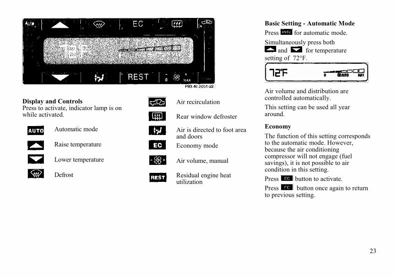
23
Display and ControlsPress to activate, indicator lamp is onwhile activated.
Automatic mode
Raise temperature
Lower temperature
Defrost
Air recirculation
Rear window defroster
Air is directed to foot areaand doorsEconomy mode
Air volume, manual
Residual engine heatutilization
Basic Setting - Automatic ModePress for automatic mode.Simultaneously press both
and for temperaturesetting of 72°F.
Air volume and distribution arecontrolled automatically.This setting can be used all yeararound.
EconomyThe function of this setting correspondsto the automatic mode. However,because the air conditioningcompressor will not engage (fuelsavings), it is not possible to aircondition in this setting.Press button to activate.Press button once again to returnto previous setting.

24
Special Settings(use only for snort duration)Defogging Windows
Switch off button,Press button.Press button repeatedlyuntil air directly upwards.
Turn wheels (1 and 3) left to open leftand right air outlets (5).
DefrostingTurn wheels (1 and 3) left to open leftand right air outlets (5).Press button. Maximum heated
and automatically controlled amount ofair is directed to the windshield andside windows.
Press button once again to returnto previous setting.
Rear Window DefrosterTurn key in steering lock toposition 2.To select, press button.To cancel, press button again.
Note:Heavy accumulation of snow and iceshould be removed before activatingthe defroster.
The rear window defroster uses a largeamount of power. To keep the batterydrain to a minimum, turn off thedefroster as soon as the window isclear.
The defroster is automaticallyturned off after a maximum of 12minutes of operation.
If several power consumers are turnedon simultaneously, or the battery isonly partially charged, it is possiblethat the defroster will automaticallyturn itself off. When this happens, theindicator lamp inside the switch startsblinking.As soon as the battery has sufficientvoltage, the defroster automaticallyturns itself back on.
Air Distribution
Press button repeatedly until therequested symbol is displayedAir VolumePress - or +side of rocker switch
until the requested blowerspeed is attained, A choice of 7blower speeds is available,To switch the automatic climatecontrol off, press -side of rockerswitch until symbol OFF isdisplayed.
The fresh air supply to the car interioris shut off.While driving, use this setting onlytemporarily, otherwise the windshieldcould fog up.To switch the automatic climatecontrol on again, press ,
, or + side of ,

25
Air Recirculation
This mode can be selected totemporarily reduce the entry ofannoying odors or dust into thevehicle's interior.Outside air is not supplied to thecar's interior.To select, press button.To cancel, press button again.The system will automaticallyswitch from recirculated air to freshair
• after approx. 5 minutes atoutside temperatures belowapprox. 40°F (6°C),
• after approx. 20 minutes, atoutside temperatures aboveapprox. 40°F (5°C),
• after approx. 5 minutes, if buttonis pressed.
If the windows should fog up fromthe inside, switch from recirculatedair back to fresh air,At high outside temperatures, thesystem automatically engages therecirculated air mode therebyincreasing the cooling capacityperformance, switching to partiallyfresh air within 20 minutes.
Residual Engine Heat Utilization
With the engine switched off, it ispossible to continue heating the interiorfor a short while.
Air volume and distribution arecontrolled automatically.
To select:Turn key in steering lock to position 1or 0 or remove key. Close air outlet inrear passenger compartment.
Press button.
This function selection will not activateif the battery charge level isinsufficient.
To cancel: Press button.
The system will automaticallyshut off
• if you turn key in steering lock toposition 2,
• after approx. 30 minutes,• if the battery voltage drops.
Dust Filter
Nearly all dust particles and pollenare filtered out before outside airenters the passenger compartmentthrough the air distribution system.
Notes:Do not obstruct the air flow byplacing objects on the air flow-through exhaust slots below therear window.
Also keep the air intake grille in frontof windshield free of snow and debris.
Important!
This vehicle is equipped with anair conditioner system that usesR-134a (HFC: hydrofluorocarbon)as a refrigerant. Repairs shouldalways be performed by a qualifiedtechnician, and refrigerant shouldbe collected in a recovery systemfor recycling.

26
Car KeysIncluded with your vehicle are
• 2 Master keys with infraredremote control
• 1 Master key1 Valet key
• 1 Flat key
Remote Control withFolding Master Key
The master key fits all locks on the car.
To release the key, press button (1).The key unfolds from the holder byitself.
The transmitter for the infrared remotecontrol is located in the key holder, thereceivers are located in the doorhandless, and next to the trunk lock.
The valet key works only in the driver'sdoor |lock and the steering lock.
The valet key will not work in thetrunk and storage compartment locks.
The flat key fits all locks on the car.
Notes:Do not give the master key to anunauthorized person.
We recommend that you carry the fiatkey with you and keep it in a safe place(e.g. your wallet) so that it is alwayshandy. Never leave the flat key in thevehicle.
Warning!
When leaving the vehicle alwaysremove the key from the steeringlock, and lock the vehicle. Do notleave children unattended in thevehicle, or with access to anunlocked vehicle. Unsupervised useof vehicle equipment may causeserious personal injury.
Obtaining Replacement Keys
Your vehicle is equipped with a theftdeterrent locking system requiring aspecial key manufacturing process. Forsecurity reasons, replacement keys canonly be obtained from your authorizedMercedes-Benz dealer.

27
Start Lock-Out
Important!
Removing the key from the steeringlock activates the start lock-out. Theengine cannot be started.
Turning the key in the steering lock toposition 2 deactivates the start lock-out.
Infrared Remote Control
The vehicle doors, trunk and fuel fillerflap can be centrally locked andunlocked, as well as the windows andsliding roof closed with infraredremote control.With vehicle centrally locked, the trunkcan also be opened by using theinfrared remote control. Aimtransmitter eye at receiver and presstransmit button twice.
1. Transmit button2. Transmitter eye and lamp for
battery check3. Key release button

28
4. Receiver, red indicator lamp(locking) and green indicatorlamp (unlocking) in left doorhandle,
5. Receiver, red indicator lamp(locking) and green indicator lamp(unlocking) in right door handle.
6. Receiver, red indicator lamp(locking) and green indicator lamp(unlocking) below trunk lock.

29
Locking and Unlocking
Aim transmitter eye (2) at a receiver(4, 5, or 6) and press transmit button.
The red or green indicator lamp on thereceiver should blink, It stops blinkingwhen the vehicle is properly locked orunlocked.
Notes:
If the trunk was previously lockedseparately, it will remain locked (seeIndex).
If the vehicle cannot be locked orunlocked by pressing the transmitbutton, then it may be necessary tochange the batteries in the transmitter(if ok, battery indicator lamp intransmitter will light briefly whentransmitting) or to synchronize thesystem, see Remote Control, Infraredin Index.
Closing Windows from Outside
Continue to press transmit button afterlocking car.The windows begin to close afterapprox. 2 seconds.
Warning!
Never close the windows If there isthe possibility of anyone beingharmed by the raising window.
In case the closing procedure causespotential danger, the closingprocedure can be immediatelyinterrupted by releasing the transmitbutton. However, the windows canonly be lowered using the powerwindow buttons inside the car.
Note:
If the side windows cannot be closedautomatically by pressing the transmitbutton of the infrared remote controlthen it may be necessary to change thebatteries in the transmitter (if ok,battery indicator lamp in transmitterwill light briefly when transmitting), orto synchronize the system, see RemoteControl, Infrared in Index.

30
Central Locking System
The entire vehicle may be locked orunlocked by using either the masterkey in driver's door or trunk lock, orcentral locking switch located in centerconsole. The central locking systemalso locks or unlocks the fuel fillerflap.
Note:If the fuel filler flap cannot be opened,refer to Fuel Filler Flap, ManualRelease (see Index).
Doors
1. Opening - pull handle
2. Unlocking
3. Locking
4. Individual door from inside:
• Push lock button down to lock.• Pull lock button up to unlock.
When you lock the car, both door lockbuttons should move down. If any onestays up, the respective door is notproperly closed.
You should then unlock the car, openand reclose this door, and lock the caragain. Each individual door can belocked with door lock button - thedriver's door can only be locked whenit is closed.
If the car has previously been lockedfrom the outside, only the door beingopened from the inside will unlock,and the alarm will come on. The otherdoor, the trunk lid and fuel filler flapremain locked.
Emergency Unlocking in Case ofAccident
The doors unlock automatically a shorttime after the roll bar is deployed in anaccident (this is intended to aid rescueand exit). However, the key in thesteering lock must be in steering lockpositions 1, 2 or returned to position 0,but not removed.

31
Notes:
In case of a malfunction in the centrallocking system the doors and trunk canbe locked and unlocked individually.To lock, turn key to position 3 or pushdown lock buttons.
To unlock, turn key to position 2 orpull up lock buttons.
Central locking switch
1. Locking2. Unlocking
The central locking switch is locatedon the center console.The doors can only be locked withthe central locking switch, if bothdoors are closed.The doors cannot be unlocked withthe central locking switch, if carwas previously locked fromoutside.If the car has previously beenlocked with the central lockingswitch, only the opened door isunlocked.
Trunk
1. Neutral posit/on - push to open2. Unlocking3. Locking (detent)4. Separate locking of trunk -
remove key in this position.
When the trunk is separately locked, itremains locked when unlocking anydoor.
To deny any unauthorized personaccess to the trunk, lock it separately.Leave only the valet key with thevehicle.
32
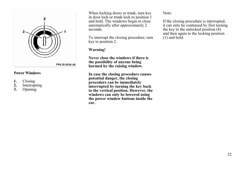
Power Windows
1. Closing2. Interrupting3. Opening
When locking doors or trunk, turn keyin door lock or trunk lock to position 1and hold. The windows begin to closeautomatically after approximately 2seconds.
To interrupt the closing procedure, turnkey to position 2.
Warning!
Never close the windows if there isthe possibility of anyone beingharmed by the raising window.
In case the closing procedure causespotential danger, the closingprocedure can be immediatelyinterrupted by turning the key backto the vertical position. However, thewindows can only be lowered usingthe power window buttons inside thecar.
Note:
If the closing procedure is interrupted,it can only be continued by first turningthe key to the unlocked position (8)and then again to the locking position(1) and hold.

33
Interior Central Locking System
1. Initial position (integrated withvehicle central locking system)
2. Separate locking of storagecompartments
3. Emergency operation
The following storage compartmentsare part of the interior central lockingsystem:
• eyeglasses compartment in thedashboard,
• console storage compartments,
• rear storage compartments,• door pockets.
Integration with vehicle centrallocking system
When locking or unlocking the vehiclefrom the outside by using the masterkey, the interior storage compartmentsand door pockets are also locked orunlocked (with lock in position 1).
Separate locking of storagecompartments
Locking:
Turn master key to position 2 andremove from lock. The storagecompartments remain locked –even if the vehicle is unlocked fromthe outside.
Unlocking:
Turn master key to position 1 andremove from lock.If the vehicle was locked from theoutside, the storage compartmentsremain in the locked mode until thevehicle is unlocked again from theoutside.
Note:If the interior storage compartments areto remain locked (for example while ina repair shop), leave only the valet keywith the vehicle.
When unlocking a door from theinside, on a vehicle previously lockedfrom the outside, the storagecompartments still remain locked.
In case of a malfunction the eyeglasses compartment can still beopened. To do so, turn the masterkey to position 3, return it toposition 1, remove it from the lock andpress button .

34
1. Indicator lamp in center console
Anti Theft Alarm System
The anti-theft alarm can bearmed/disarmed with any of yourvehicle's keys or infrared remotecontrol by locking/unlocking eitherdoor or the trunk.
A blinking lamp (1) indicates that thealarm is armed.
The antitheft alarm is disarmed whenunlocking the driver door or the trunkwith any of your vehicle's keys orinfrared remote control.
Operation:
Once the alarm system has beenarmed, the exterior vehicle lamps willflash and the horn will soundintermittently when someone:
• opens a door,• opens the trunk,• opens the hood,• removes the radio,• switches on or bridges the
ignition circuit,• steps on the brake pedal,• opens the storage compartment
between the front seats.
The alarm will last approximately 150seconds in the form of blinking exteriorlamps. At the same time an alarm hornwill sound intermittently for 60seconds, pause for 30 seconds, andrepeat for another 60 seconds.
The alarm will stay on even if theactivating element (a door, forexample) is immediately closed.
Note:We recommend that you carry the flatkey safely with you so that it is alwayshandy. This key has the same functionas the master key.

35
Power Seats
The switches are located in each frontdoor.Turn key in steering lock to position 1or 2 (with either door open, the powerseats can also be operated with the keyremoved or in steering lock position 0).
Adjusting
A. Seat cushionB. BackrestC. Head restraint (with shoulder belt
height adjustment)
Adjust the head restraint so that theupper portion of the shoulder belt islocated as close as possible to themiddle of the shoulder. The headrestraint can be tilted forward by hand.
Note:To prevent the backrest from touchingthe soft top storage compartment coverwhen the seat cushion is moved back,the backrest will automatically move toa more upright position.
When reclining the backrest, the seatcushion will automatically moveforward to prevent the backrest fromtouching the soft top storagecompartment cover.
Warning!
When leaving the vehicle alwaysremove the key from the steering lock.
The power seats can also be operatedwith the driver's or passenger dooropen. Do not leave childrenunattended in the vehicle.Unsupervised use of vehicleequipment may cause serious personalinjury.
Do not adjust the driver's seat whiledriving. Adjusting the seat whiledriving could cause the driver to losecontrol of the vehicle.
Never ride in a moving vehicle withthe seat back reclined. Sitting in anexcessively reclined position can bedangerous. You could slide under theseat belt in a collision. If you slideunder it, the belt would apply force atthe abdomen or neck. That couldcause serious or even fatal injuries.The seat back and seat belts providethe best restraint when the wearer isin an upright position and belts areproperly positioned on the body.
The rear storage area should neverbe occupied by passengers since thevehicle is a 2 seater. Furthermore,there is a risk of injury in the rear byadjusting the power assisted frontseats.
Never place hands under seat or nearany moving parts while a seat is beingadjusted.

36
Storing Position in MemoryD Memory buttonE Position buttons "1", "2"
and "3"
After the seat and head restraint arepositioned, push memory button D,release, and within 3 seconds pushposition button "1". Two additional setsof positions may be stored into memoryusing position buttons "2" and "3".
Adjusting
A Seat cushionB BackrestC Head restraint
(with shoulder belt heightadjustment)
Adjust the head restraint so that theupper portion of the shoulder belt islocated as close as possible to themiddle of the shoulder. The headrestraint can be tilted forward by hand.Note:To prevent the backrest from touchingthe soft top storage compartment coverwhen the seat cushion is moved back,the backrest will automatically move toa more upright position. Whenreclining the backrest, the seat cushionwill automatically move forward toprevent the backrest from touching thesoft top storage compartment cover.
Warning!Never ride in a moving vehicle withthe seat back reclined. Sitting in anexcessively reclined position can bedangerous. You could slide under theseat belt in a collision, if you slideunder it, the belt would apply forceat the abdomen or neck. That couldcause serious or even fatal injuries.In a normal seated position the beltsprovide the best restraint for thewearer, as they are only thenproperly located on the body.The rear storage area should neverbe occupied by passengers since thevehicle is a 2 seater.Furthermore, there is a risk ofinjury in the rear by adjusting thepower assisted frontseats.
Using the same position button, thesteering column position and rear viewmirror positions will also be storedtogether with the seat position.Adjusting steering column and mirrorssee Index.
Recalling Stored Positions
Press position button "1", "2" or "3"and hold until seat/head restraint/steering wheel/mirror movement hasstopped.
Note:For safety reasons, the seat/headrestraint/steering wheel/mirrormovement stops after releasing theposition button.

37
Backrest
Folding forward:Lift lever and fold forwards.
Folding back:Fold backrest back until it audiblylocks in place.
Warning!
The seat belts provide protectiononly with the backrest locked inplace and, therefore, must be lockedin place with the vehicle in motion.Do not drive the car when the seat-back is not locked in place.
Note:If the backrest and seat belt warninglamp does not go out, but is instead litcontinuously, then a backrest is notengaged in its lock.
Always provide sufficient room behindthe backrest and fold the backrest allthe way back until it can be heardlocking in place.
The warning lamp goes out as soon asboth backrests are locked in place.
If both backrests are locked in placeand the warning lamp does not go out,have the system checked at yourauthorized Mercedes-Benz dealerimmediately.

38
Switch is located on side of seat.
BackrestFolding forward:Lift lever and fold forwards.Folding back:Fold backrest back until it audiblylocks in place.Warning!The seat belts provide protectiononly with the backrest locked inplace and, therefore, must be lockedin place with the vehicle in motion.Do not drive the car when the seat-back is not locked in place.
Note:If the backrest and seat belt warninglamp does not go out, but is instead litcontinuously, then a backrest is notengaged in its lock.Always provide sufficient room behindthe backrest and fold the backrest allthe way back until it can be heardlocking in place.The warning lamp goes out as soon asboth backrests are locked in place.If both backrests are locked in placeand the warning lamp does not go out,have the system checked at yourauthorized MERCEDES-BENZ dealerimmediately.
Multicontour Seat (optional)
1. Seat cushion depth
2. Backrest bottom
3. Backrest center
4. Side bolster adjustment
Some models may be equipped withmulticontour seats. These seats havemovable seat cushions, and inflatableair cushions built into the backrest toprovide additional lumbar and sidesupport.
The seat cushion movement andamount of backrest cushion height andcurvature can be continuously variedwith regulators (1,2 and 3) after turningthe key in steering lock to position 2.
The side bolsters of the backrest can beadjusted with rocker switch (4):
• press down forward end -increase side support,
• press down rearward end -decrease side support.
If the engine is turned off, the lastcushion setting is retained in memory,and automatically adjusts the cushion tothis setting when the engine is restarted.

39
Heated Seats
The seat heaters can be switched onwith the key in steering lock turned toposition 1 or 2.
Press switch to turn on heater:
1. Normal heating mode. Oneindicator lamp in the switchlights up.
2. Rapid heating mode. Bothindicator lamps in the switchlight up.After approximately 5 minutes inthe rapid heating mode, the heaterautomatically switches to normaloperation and only one indicatorlamp will stay on.
Turning off heater:
If one indicator lamp is on, press upperhalf of switch.
If both indicator lamps are on, presslower half of switch.
If left on, the heater automatically turnsoff after approximately 30 minutes ofoperation.
Note:When in operation, the seat heaterconsumes a large amount of power. Itis advisable not to use the seat heaterlonger than necessary.
The seat heaters may automaticallyswitch off if too many powerconsumers are switched on at the sametime, or if the battery charge is low.
When this occurs, the indicator lamp inthe switch will blink (both indicatorlamps blink during rapid seat heating).The seat heaters will switch on againautomatically as soon as sufficientvoltage is available.
If the blinking of the indicator lamps isdistracting to you, the seat heaters canbe switched off.
40
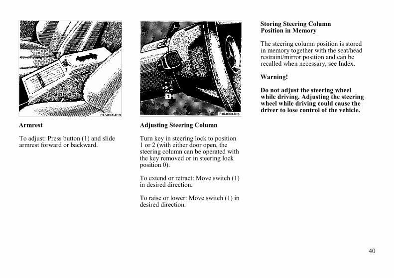
Armrest
To adjust: Press button (1) and slidearmrest forward or backward.
Adjusting Steering Column
Turn key in steering lock to position1 or 2 (with either door open, thesteering column can be operated withthe key removed or in steering lockposition 0).
To extend or retract: Move switch (1)in desired direction.
To raise or lower: Move switch (1) indesired direction.
Storing Steering ColumnPosition in Memory
The steering column position is storedin memory together with the seat/headrestraint/mirror position and can berecalled when necessary, see Index.
Warning!
Do not adjust the steering wheelwhile driving. Adjusting the steeringwheel while driving could cause thedriver to lose control of the vehicle.

41
Seat Belts and SupplementalRestraint System (SRS)
Your vehicle is equipped with lap-shoulder seat belts, emergencytensioning retractors for the seat belts,driver airbag and knee bolster andpassenger airbag and knee bolster.
Seat Belts
Important!
Laws in most states and all Canadianprovinces require seat belt use.
All states and provinces require use ofchild restraints that comply with U.S.Federal Motor Vehicle Safety Standard213 and Canadian Motor VehicleSafety Standard 213.1. We stronglyrecommend their use.
The seat belts provide protectiononly with the backrest locked inplace. If the seat belt warning lampdoes not go out, but is instead lit con-tinuously, then a backrest is notengaged in its lock.
Never ride in a moving vehicle withthe seat back reclined. Sitting in anexcessively reclined position can bedangerous. You could slide under theseat belt in a collision. If you slideunder it, the belt would apply forceat the abdomen or neck. That couldcause serious or even fatal injuries.The seat back and seat belts providethe best restraint when the wearer isin an upright position and belts areproperly positioned on the body.
Seat Belt Warning System
With the key in steering lockposition 2, an audible warning soundsfor a short time if the driver's seat beltis not fastened.
Warning!
Failure to wear and properly fastenand position your seat belt greatlyincreases your risk of injuries andtheir likely severity in an accident.You and your passengers shouldalways wear seat belts.
If you are ever in an accident, yourinjuries can be considerably moresevere without your seat beltproperly buckled. Without your seatbelt buckled, you can hit the interiorof the vehicle or be ejected from it.You can be seriously injured orkilled.
In the same crash, the possibility forinjury or death is lessened with yourseat belt buckled.

42
1. Latch plate2. Buckle3. Release button
Fastening of Seat Belts
Pull belt with latch plate (1) acrossshoulder and lap. Push latch plate (1)into buckle (2) until it clicks. The lapbelt should be positioned as low aspossible on your hips and not acrossthe abdomen. Do not twist the belt. Atwisted seat belt may cause injury.
Press switch (4) to adjust seat belt sothat the shoulder portion is located asclose as possible to the middle of yourshoulder.
The shoulder portion of the seat beltmust be pulled snug and checked forsnugness immediately after engaging itand during driving. Tighten the lapportion to a snug fit by pullingshoulder portion up.
For safety reasons, avoid adjusting theseat or seat back into positions whichcould affect the correct seat beltposition.

43
Unfastening of Seat Belts
Push in the red button (3) in the beltbuckle (2).
Allow the retractor to completelyrewind the seat belt by guiding thelatch plate (1).
Operation:
The inertia reel stops the belt fromunwinding during sudden vehicle stopsor when quickly pulling on the belt.
The locking function of the reel may bechecked by quickly pulling on the belt.
Note:For cleaning and care of the seat belts,see Cleaning and Care of the Vehiclein Index.
Warning!
USE SEAT BELTS PROPERLY.
• Each occupant should weartheir seat belt at all times,because seat belts help reduce the likelihood of andpotential severity of injuriesin accidents, including roll-overs."SRS" (driver airbag,passenger airbag), "ETR"(seat belt emergency tensioningretractors), and knee bolstersare designed to enhance theprotection offered to properlybelted occupants in certainfrontal impacts which exceedpreset deployment thresholds.
• Improperly positioned seatbelts do not provide maximumprotection and may causeserious injuries in case of anaccident.

44
• Never wear the shoulderbelt under your arm, againstyour neck or off your shoulder.In a crash, your body wouldmove too far forward. Thatwould increase the chance ofhead and neck injuries. The beltwould also apply top much forceto the ribs, which could severelyinjure internal organs such asyour liver or spleen.
• Position the lap belt as lowas possible on your hipsand not across theabdomen. If the belt ispositioned across yourabdomen, it could causeserious injuries in a crash.
• Each seat belt should neverbe used for more than oneperson at a time. Do notfasten a seat belt around aperson and objects.
• Belts should not be worntwisted. In a crash, youwouldn't have the full widthof the belt to take impactforces. The twisted beltagainst your body couldcause injuries.
• Pregnant women shouldalso use a lap-shoulder belt.The lap belt portion shouldbe positioned as low aspossible on the hips toavoid any possible pressureon the abdomen.
Warning!
USE CHILD RESTRAINTSPROPERLY.
• Infants and small childrenmust be seated in an infantor child restraint system,which is properly securedby a lap belt or lap beltportion of a lap-shoulderbelt. Children could beendangered in an accident iftheir child restraints are notproperly secured in the vehicle.
• Rear-facing child restraintsmust not be used in thefront seat. They could bestruck by the airbag when itinflates in a crash. If thishappens, a child in therestraint could be seriouslyinjured.
• Children too big for childrestraint systems shoulduse regular seat belts.Position shoulder belt acrosschest and shoulder, not face orneck. A booster seat may benecessary to achieve proper beltpositioning.

45
Supplemental Restraint System(SRS)
The SRS uses two crash severity levels(thresholds) to activate either the ETRor airbag or both. Activation dependson the direction and severity of theimpact, exceeding the thresholds andfastening of the seat belt.
Seat belt fastened
• first threshold exceeded:ETR activates
• second threshold exceeded:airbag also activates
Seat belt not fastened
• first threshold exceeded:airbag activates, but not ETR
Driver and front passenger systemsoperate independently from each other.
Emergency TensioningRetractor (ETR)
The seat belts are equipped withemergency tensioning retractors. Thesetensioning retractors are located in eachbelt's inertia reel and becomeoperationally ready with the key insteering lock position 1 or 2.
The emergency tensioning retractorsare designed to activate only when theseat belts are fastened during frontaland front-angled impacts exceeding thefirst threshold of the SRS. They re-move slack from the belts in such away that the seat belts fit more snuglyagainst the body, restricting its forwardmovement as much as possible.
In cases of other frontal impacts, roll-overs, certain side impacts, rearcollisions, or other accidents withoutfrontal forces, the emergencytensioning retractors will not beactivated. The driver and passengerwill then be protected by the fastenedseat belts and inertia reel in the usualmanner.
For seat belt and emergency tensioningretractor safety guidelines, see SafetyGuidelines in Index.

46
Airbags
1. Driver airbag2. Front passenger airbag3. Side impact airbag
The most effective occupant restraintsystem yet developed for use inproduction vehicles is the seat belt. Insome cases, however, the protectiveeffect of a seat belt can be furtherenhanced by an airbag.
The driver airbag is located in thesteering wheel hub. The passengerairbag is located in the dashboardahead of the passenger.
The side impact airbags are located inthe doors. In conjunction with wearingthe seat belts with emergencytensioning retractors, the airbags canprovide increased protection for thedriver and passenger in certain majorfrontal and front-angled and sideimpacts.
The operational readiness of theairbag system is verified by theindicator lamp "SRS" in theinstrument cluster. If no fault isdetected, the lamp will go out afterapproximately 4 seconds; after the lampgoes out, the system continues tomonitor the components and circuitryof the airbag system
and will indicate a malfunction bycorning on again.The following system components aremonitored or undergo a self-check:crash-sensor, airbag ignition circuits,driver and passenger seat belt buckles.Initially, when the key is turned fromsteering lock position 0 to positions 1or 2, malfunctions in the crash-sensorare detected and indicated (the "SRS"indicator lamp stays on longer than 4seconds).
In the operational mode, after theindicator lamp has gone outfollowing the initial check, inter-ruptions and short circuits in the
47
airbag ignition circuit and in the driverand passenger seat belt buckleharnesses, and low voltage in the entiresystem are detected and indicated.In the event a malfunction of the "SRS"is indicated as outlined above, the"SRS" may not be operational. Westrongly recommend that you visit anauthorized Mercedes-Benz dealerimmediately to have the systemchecked; otherwise the "SRS" may notbe activated when needed.
Front Airbags
The driver and passenger front "SRS"airbags are designed to activate only incertain frontal and front-angledimpacts.
The front passenger airbag deploysonly if the passenger seat is occupied.
Note:Do not place heavy objects on frontpassenger seat, otherwise the frontairbag may deploy.
Side Airbags
The side impact "SRS" airbags aredesigned to activate only in certain sideimpacts. Only the impacted side airbagdeploys.
The passenger side airbag deploys onlyif the passenger seat is occupied.
Note:Do not place heavy objects on frontpassenger seat, otherwise the sideairbag may deploy.
Important!
The "SRS" airbags are designed toactivate only in certain frontal,front-angled or side impacts. Onlyduring these types of Impacts, if ofsufficient severity to meet thedeployment thresholds, will theyprovide their supplementalprotection. The driver and passengershould always wear the seat belts,otherwise it is not possible for theairbags to provide their intendedsupplemental protection.
In cases of other frontal Impacts,roll-overs, other side impacts, rearcollisions, or other accidents withoutsufficient forces,
the airbag will not be activated.The driver and passengers willthen be protected by thefastened seat belts.
We caution you not to rely on thepresence of an airbag in order toavoid wearing your seatBelt
The "SRS" is designed to reduce thepotential of injury in certain frontal,front-angled and side impacts whichmay cause injuries, however, nosystem available today can totallyeliminate injuries and fatalities.
The activation of the "SRS"temporarily releases a small amountof dust from the airbags. This dust,however, is neither injurious to yourhealth, nor does it indicate a fire inthe vehicle.
The service life of the airbagsextends to the date indicated on thelabel located on the driver-side doorlatch post. To provide continuedreliability after that date, theyshould be inspected by an authorizedMercedes-Benz dealer at that timeand replaced when necessary.

48
Warning!
It is very important for your safety toalways be in a properly seatedposition and to wear your seat belt.
For maximum protection in the eventof a collision always be in normalseated position with your backagainst the seat back. Fasten yourseat belt and ensure that it isproperly positioned on the body.
For unobstructive inflation of sideairbags, keep door pocket lidsclosed.
Since the airbag inflates withconsiderable speed and force, aproper seating position will keep youin a safe distance from the airbag:
• Sit properly belted in anupright position with yourback against the seat back.
• Do not lean with your heador chest close to the steeringwheel or dashboard.
• Adjust the driver seat as faras possible rearward, stillpermitting proper operationof vehicle controls.
• Adjust the passenger seatas far as possible rearwardfrom the dashboard,especially when a childrestraint is installed.
• Infants and small childrenshould only be seated in aninfant or child restraintwhich is properly securedby the seat belt.
• Rear-facing child restraintsmust not be used in a frontseat.
Failure to follow these instructionscan result in severe injuries to you orother occupants.

49
Safety Guidelines for the Seat Belt,Emergency Tensioning Retractorand Airbag
Warning!
• Damaged belts or belts thatwere highly stressed in anaccident must be replaced andtheir anchoring points must alsobe checked. Use only beltsinstalled or supplied by anauthorized Mercedes-Benzdealer.
• Do not pass belts over sharpedges.
• Do not make any modificationthat could change theeffectiveness of the belts.
• The "SRS" is designed tofunction on a one-time-onlybasis. An airbag or emergencytensioning retractor (ETR) thatwas activated must be replaced.
• No modifications of any kindmay be made to any componentsor wiring of the "SRS". Thisincludes the installation ofadditional trim material, badgesetc. over the steering wheel hubor front passenger airbag coverand installation of additionalelectrical/electronic equipmenton or near "SRS" componentsand wiring.
• Several airbag system com-ponents at the steering wheel gethot after the air-bag has inflated.Don't try to touch them.
• Improper work on the system,including incorrect installationand removal, can lead to possibleinjury through an uncontrolledactivation of the "SRS".
• In addition, through improperwork there is the risk ofrendering the "SRS"inoperative. Work on the "SRS"must therefore only beperformed by an authorizedMercedes-Benz dealer.
• When scrapping the airbag unitor emergency tensioningretractor, it is mandatory tofollow our safety instructions.These instructions are availableat your authorized Mercedes-Benz dealer.
When you sell the vehicle we stronglyurge you to give notice to thesubsequent owner that it is equippedwith an "SRS" by alerting him to theapplicable section in the Owner'sManual.

50
Infants and Child RestraintSystems
We recommend that all infants andchildren be restrained at all times whilethe vehicle is in motion.The passenger seat has a special seatbelt retractor for secure fastening of achild restraint. To use, fasten childrestraint with seat belt: Follow childrestraint instructions for routing. Thenpull shoulder belt out completely. Slideswitch located on side of passenger seatto position . Let the belt retract. Itis now locked. Push down on childrestraint to take up any slack.
Important!
The use of infant or child restraints isrequired by law in all 50 states and allCanadian provinces.
Infants and small children should beseated in an infant or child restraintsystem, which is properly secured bythe lap-shoulder belt, and that complieswith U.S. Federal Motor SafetyStandard 213 and Canadian MotorVehicle Safety Standard 213.1.
A statement by the child restraintmanufacturer of compliance with thisstandard can be found on theinstruction label on the restraint and inthe instruction manual provided withthe restraint.When using any infant or childrestraint system, be sure to carefullyread and follow all manufacturer'sinstructions for installation and use.
Warning!
Rear-facing child restraints must notbe used in a front seat They could bestruck by the airbag when it inflatesin a crash. If this happens, a child inthe restraint could be seriouslyinjured.
Infants and small children shouldnever be held on the lap while thevehicle is in motion. During anaccident they would be almostimpossible to hold, and could becrushed between the adult and thedashboard.
Infants and small children shouldnever share a seat belt with anotheroccupant During an accident, theycould be crushed between theoccupant and seat belt.
Children too big for child restraintsystems should use regular seatsbelts. Position the shoulder beltacross the chest and shoulder, not theface or neck. A booster seat may benecessary to achieve proper beltpositioning.
When the child restraint is not in use,remove it from the car or secure itwith the seat belt to prevent the childrestraint from becoming a projectilein the event of an accident.
U.S.A. Models onlySince 1986 all U.S. child restraintscomply with U.S. regulations withoutthe use of a tether strap.
Canada Models onlyThis vehicle can be equipped withtether anchorages for a top tether strap.Consult your authorized Mercedes-Benz dealer for installation of theseanchorages.

51
Steering Lock
0. The key can be withdrawn in thisposition only. The steering islocked with the key removed fromthe steering lock. The key can beremoved only with the selectorlever in position "P". Afterremoving the key or with the keyin steering lock position 0, theselector lever is locked in position"P".
1. Steering is unlocked.(If necessary, move steering wheelslightly to allow the key to beturned clockwise to position 1.)
Most electrical consumers can beoperated. For detailed informationsee respective subjects.
2. Driving position.
3. Starting position.
Refer to Index for Starting andturning off engine.
Warning!
When leaving the vehicle alwaysremove the key from the steeringlock. Do not leave childrenunattended in the vehicle.Unsupervised use of vehicleequipment may cause seriouspersonal injury.
Notes:A warning will sound when thedriver's door is opened with the key insteering lock positions 1 or 0.
With the engine at idle speed, thecharging rate of the alternator(output) is limited.
It is therefore recommended to turnoff unnecessary electrical consumerswhile driving in stop-and-go traffic.This precaution helps to avoiddraining of the battery.
Unnecessary drain on the battery andcharging system may be minimizedby turning off the following powerconsumers, for example: heated seats,rear window defroster. In addition,the automatic climate control blowerspeed should be set to stage "1".
Caution!
To prevent accelerated batterydischarge and a possible dead battery,always remove the key from thesteering lock. Do not leave the key insteering lock position 0.

52
Combination Switch
1. Low beam (exterior lampswitch position )
2. High beam (exterior lampswitch position )
3. High beam flasher (high beamavailable independent ofexterior lamp switch position)
4. Turn signals, right5. Turn signals, left
To signal minor directional changes,such, as changing lanes on a highway,move combination switch to the pointof resistance only and hold it there.
To operate the turn signalscontinuously, move the combinationswitch past the point of resistance (upor down). The switch is automaticallycanceled when the steering wheel isturned to a large enough degree.
6. Press switch briefly:One wipe without washer water(select only if window is wet)
Press switch past resistance point:
Windshield washer, windshieldwiper;headlamp cleaning system only inexterior lamp switch positions- or (except xenonlamps).Canada only: also in positionwhen the engine is running)
7. Windshield wiperWiper offI Intermittent wipingII Normal wiper speedIII Fast wiper speed
Note:The windshield washer reservoir,hoses and nozzles are automaticallyheated.

53
Windshield Washer Fluid MixingRatio
For temperatures above freezing:
MB Windshield Washer Concentrate"S" and water
1 part "S" to 100 parts water(40 ml "S" to 1 gallon water).
For temperature below freezing:
MB Windshield Washer Concentrate"S" and commercially availablepremixed windshield washersolvent/antifreeze
1 part "S" to 100 parts solvent(40 ml "S" to 1 gallon solvent).
Windshield Wiper Smears
If the windshield wiper smears thewindshield, even during rain, activatethe washer system as often asnecessary. The fluid in the washerreservoir should be mixed in the correctratio.
Blocked Windshield Wiper
If the windshield wiper becomesblocked (for example, due to snow),switch off the wiper motor.For safety reasons before removing iceor snow, remove key from steeringlock. Remove blockage.Activate combination switch again(key in steering lock position 1).
Emergency Operation ofWindshield Wiper
In case of windshield wipermalfunction, turn combination switchto wiper setting II.
Have the system checked at yourauthorized MERCEDES-BENZ dealeras soon as possible.
Signaling Turns with HazardFlasher in Use
For example, when the vehicle is beingtowed (key in steering lock turned toposition 2):With hazard flasher on, activatecombination switch for left or rightturn signal - only the selected turnsignal will blink.
Upon canceling the turn signal, all fourturn signals will operate again.
Turn Signal Failure
If one of the turn signals fails, the turnsignal indicator system flashes andsounds at a faster than normal rate.

54
Exterior Lamp Switch
Canada only:When the engine is running, the lowbeam (includes parking lamps, sidemarker lamps, taillamps, license platelamps and instrument panel lamps) areautomatically switched on.
When shifting from a driving positionto position "N" or "P", the low beamswitches off (2 seconds delay).For nighttime driving the exteriorlamp switch should be turned toposition to permit activation ofthe high beam headlamps.
Off
Parking lamps (includes sidemarker lamps, taillamps,license plate lamps,instrument panel lamps)Canada only: When theengine is running, the lowbeam is additionallyswitched on.Parking lamps plus lowbeam or high beamheadlamps (combinationswitch pushed forward)Standing lamps, right (turnleft one stop).Standing lamps, left (turnleft two stops)Fog lamps (pull out onestop) with parking and/orheadlamps onRear fog lamp (pull out to2nd detent) In addition tofog lamps. Indicator lamp inlamp switch comes on
Standing Lamps
When the vehicle is parked on thestreet the standing lamps (right or leftside parking lamps) can be turned on,making the vehicle more visible topassing vehicles.The standing lamps can only beoperated with the key in steeringlock position 0 or 1.
Note:With the key removed and a door open,a warning sounds if the vehicle'sexterior lamps (except standing lamps)are not switched off.
Fog lamps will operate with theparking lamps and the low or highbeam headlamps. Fog lamps shouldonly be used in conjunction with lowbeam headlamps. Consult your stateMotor Vehicle Regulations regardingallowable lamp operation.Fog lamps are automaticallyswitched off when the exteriorlamp switch is turned toposition .

55
Exterior Rear View Mirrors
The switch is located in the centerconsole.Turn key in steering lock to position 2.
First select the mirror to be adjusted -turn switch:
1 Left mirror2 Right mirror
To adjust, move the switch forward,backward or to either side.
With the key in steering lock position2, the driver's side mirror reflectionbrightness responds to changes in lightsensitivity.
With gear selector lever in position"R", or with the interior lamp switchedon, the mirror brightness does notrespond to changes in light sensitivity.
Note:The exterior mirrors have electricallyheated glass. The heater switches onautomatically, depending on outsidetemperature.
If the mirror housing is forciblypivoted from its normal position, itmust be repositioned by applying firmpressure until it snaps into place.
Warning!Exercise care when using thepassenger-side mirror. Thepassenger-side exterior mirror isconvex (outwardly curved surfacefor a wider field of view). Objects inmirror arc closer than they appear.Check your inside rear view mirroror glance over your shoulder beforechanging lanes.
Storing Mirror Positions inMemory
The exterior rear view mirror positionsare stored in memory with theseat/head restraint/ steering columnposition and can be recalled whennecessary, see Index.
Inside Rear View Mirror
Manually adjust the mirror.Use your inside mirror to determinethe size and distance of objects seen inthe passenger convex mirror.
Antiglare Night Position
With the key in steering lock position2, the mirror reflection brightnessresponds to changes in light sensitivity.
With gear selector lever in position"R", or with the interior lamp switchedon, the mirror brightness does notrespond to changes in light sensitivity.

56
Night Security Illumination
When exiting the vehicle after drivingwith the exterior lamps on, they switchon again for added security forapproximately 30 seconds after closingthe last door. The lamp-on time periodcan be changed at your Mercedes-Benzdealer.
Sun Visors
Swing sun visors down to protectagainst sun glare.
If sunlight enters through a sidewindow, disengage visor from innermounting and pivot to the side.
Illuminated Vanity Mirrors
With the visor engaged in its innermounting, the lamp can be switched onby opening the cover.
Warning!
Do not use the vanity mirror whiledriving.

57
1. Adjusting knob
Instrument Lamps
Rotate adjusting knob (1) to varyintensity of instrument lamps.
Display Illumination
Press adjusting knob to brieflyilluminate the display (with keyremoved or in steering lock position 0or 1).
With exterior lamps switched on thedisplay illumination becomesautomatically dim.
Rotate adjusting knob clockwise to itsslop to override the dimmedillumination.
Trip odometer
To reset:
• Press adjusting knob (1) once(with key in steering lockposition 2).
• Press adjusting knob (1) twice(with key removed or inlock position 0 or 1).
Clock
Adjusting clock one minute ahead orback:
Pull out adjustment knob (2), brieflyturn to the right respectively left andrelease knob.
Adjusting clock more than one minuteahead or back: Pull out adjustmentknob (2), turn to the right respectivelyleft and hold until the desired time isset. Within the first 2 seconds, theminute hand advances 8 minutes andadvances another 8 minutes everyadditional second thereafter.

58
Garage Door Opener
1 Remote control transmitterlocated on inside rear view mirror
2 Portable remote control transmitter
The built-in remote control is capableof operating up to three separatelycontrolled objects.
Warning!When programming a garage dooropener, the door moves up ordown.
When programming or operatingthe remote control make sure thereis no possibility of anyone beingharmed by the moving door.
Note:
Certain types of garage door openersare incompatible with the integratedopener. If you should experiencedifficulties with programming thetransmitter, contact your authorizedMercedes-Benz dealer or callMercedes-Benz Customer AssistanceCenter (in the U.S.A. only) at 1-800FOR MERCEDES.
Programming or reprogramming theremote control:1. Turn key in steering lock to
position 1 or 2.2. Press and hold one button of
the remote control located onthe inside rear view mirror untilits control light begins to flash ata rate of about once a second.Continue holding down thebutton.Note:The light blinks immediately if theremote control is being programmedfor the first time, or if its memorywas previously erased, If you arereprogramming a previously usedbutton, the light will flash afterabout 20 seconds.
3. Hold end opposite to battery ofportable remote control againstthe inside rear view mirror trans-mitter to be programmed. Whilestill holding down the button onthe transmitter on the inside rearview mirror, press down the button on your portable remotecontrol, until the inside rear view

59
mirror remote control light starts toflash rapidly. This means that theintegrated remote control hasaccepted the frequency and code ofthe portable transmitter.
4. If you wish, repeat the procedure foreach remaining button.
Operation of remote control:
1. Turn key in steering lock toposition 1 or 2.
2. Select and press the appropriatebutton (I, 2or 3) to activate theremote controlled device. Theremote control transmitter continuesto send the signal as long as thebutton is pressed - up to 20 seconds.
Erasing the remote controlmemory:
1. Turn key in steering lock toposition 1 or 2.
2. Simultaneousy holding downbuttons 1 and 3 for approximately20 seconds, or until the control lightblinks rapidly, will erase the codesof all three channels.
Storage Compartment(Eyeglasses Compartment) inthe Dashboard
1. Storage compartment(eyeglasses compartment)
2. Button for storage compartment3. Lock
Opening compartment (1): Pressbutton (2).
Note:The storage compartments and doorpockets may be locked and unlockedby using the master key in lock (3).For interior central locking systemsee Index.
Locking:Turn master key in lock (3) to theright and remove.
Unlocking:Turn master key back to verticalposition.
Caution!
Keep compartment lids closed. Thiswill prevent stored objects frombeing thrown about and injuringvehicle occupants during anaccident.
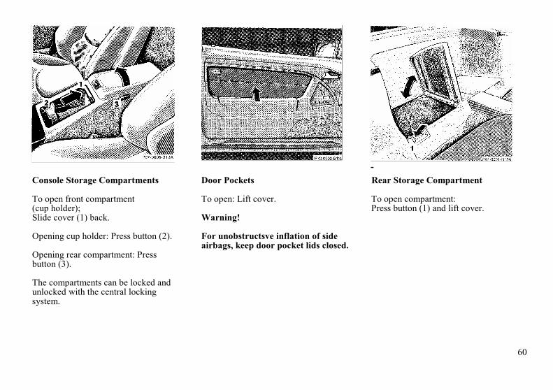
60
-Console Storage Compartments
To open front compartment(cup holder);Slide cover (1) back.
Opening cup holder: Press button (2).
Opening rear compartment: Pressbutton (3).
The compartments can be locked andunlocked with the central lockingsystem.
Door Pockets
To open: Lift cover.
Warning!
For unobstructsve inflation of sideairbags, keep door pocket lids closed.
Rear Storage Compartment
To open compartment:Press button (1) and lift cover.

61
Ashtray in center console
Ashtray with Lighter
By touching the bottom of the coverlightly, the ashtray opens automatically.Prior to removing the ashtray insertmove gear selector lever to position"N".
Warning!
With the gear selector lever inposition "N", turn off the engine andset the parking brake. Otherwise thevehicle might move unintentionally.
To remove ashtray:Push sliding knob (1) toward theright to eject the insert.
To install ashtray:Install insert into ashtray frameand push down to engage.
Lighter
1. Lighter
Turn key in steering lock toposition 1 or 2.Push in lighter (1); it will pop outautomatically when hot.
Warning!
Never touch the heating element orsides of the lighter, hold at knobonly.

62
Interior Lighting
The switch is located above the insiderear view mirror.
Interior Lamp
1. Interior lamps are switched on,and off delayed, when unlocking orlocking the vehicle, or whenopening either door.However, there will be no delaywhen the key is in steering lockposition 2.
2. Interior lamps switched off.3. Interior lamps switched on
continuously.
Reading Lamps
4. Left reading lamp switched on,5. Reading lamps switched off.6. Right reading lamp switched on.
Entrance Lamps, Exit Lamps
Entrance lamps are located in thefootwells under the dashboard.Exit lamps are located in the doorpockets.These lamps are switched on and offby the door contact switches.
Note:To prevent the vehicle battery frombeing discharged, do not leave doorsopen for a long period of time.

63
Power Windows
The switch is located in the centerconsole.Turn key in steering lock toposition 2.Press switch up to resistance point:
to closeto open
Release switch when window is indesired position.
Press switch past resistance pointand release - window lowers to fullyopen position, To interrupt procedure,briefly press or .
Warning!
When leaving the vehicle, alwaysremove the key from the steeringlock. Do not leave childrenunattended in the vehicle.Unsupervised use of vehicleequipment may cause seriouspersonal injury.
Note:
The power windows can also be closedwith the key or infrared remote controlwhile locking the vehicle doors ortrunk (see Central Locking System inIndex).
Important!
Do riot close a door with the windowsfully closed while the power supply isinterrupted (battery disconnected orempty). Doing so could damage thewindow frame.The power windows should first beresynchronized.After a power interruption, firstsynchronize the windows to enableactivation of the soft top.
Synchronizing Power Windows
When opening a door after the powersupply' was interrupted (batterydisconnected or empty), the windowwill open slightly, indicating that theExpress feature should beresynchronized.
Press side of power windowswitch until the window is completelyclosed and hold for additional 2seconds. Repeat procedure for eachwindow.
The automatic full opening and closingprocedure of the windows should nowbe restored.

64
Roll Bar
The switch is located in the centerconsole.
Turn key in steering lock to position 2.Press switch
Upper half = to raiseLower half = to lower
The lowering or raising procedure isimmediately interrupted by releasing theroll bar switch.
If the roll bar was raised using theswitch, it will be automatically loweredwhen activating the soft top switch.
The roll bar will be automaticallyraised in an accident or in a potentiallydangerous driving situation. A ratchetnoise can be heard when the roll bar isautomatically raised.
The roll bar can be lowered again afteran automatic deployment by pressingthe upper half of the roll bar switch (forat least 5 seconds) until the roll bardrive mechanism audibly engages.Then press the lower half of the switchto lower the roll bar.
Warning!
This vehicle is a two occupantvehicle. The rear storage area shouldnever be used by any persons.Raising or lowering of the roll barcould injure rear seated occupants.
Before operating the roll bar switchmake sure that the roll bar's path Isclear and no persons due toinattention are injured by the movingroll bar.
For your own safety we recommendto drive with the roll bar raised, if
• the outside temperature isbelow +5°F(-15°C)
• the soft top is closed andpets are placed in the rearstorage area.
Items being transported in the areabehind the seats should be placed insuch a manner as not to affect themovement of the roll bar when beingraised.

65
Note:
If the indicator lamps in the switch areblinking or if the warning lamp in theinstrument cluster comes on, then amalfunction has been detected.In this case, drive only with the roll barraised until the problem has beencorrected. Raise the roll bar by pressingthe upper half of the roll bar switch.The indicator lamps in the switch willgo out, however, the warning lamp inthe instrument cluster will stay on.
Have the system checked at yourauthorized Mercedes-Benz dealer assoon as possible.
Important!
The roll bar is intended to be a safetyenhancement to the other featuresdesigned into the vehicle. No system inany vehicle can eliminate thepossibility of serious injury or fatalityin an accident. Properly fastened seatbelts and child restraints must be used!
Sunshade
To close:Slide handle of sunshade alongPanorama roof and engage in lock.To open:Disengage handle from lock, andguide sunshade until fully retracted.Do not let the sunshade snap back.
Warning!
Do not operate the sunshade whiledriving. Adjusting the sunshadewhile driving could cause the driverto lose control of the vehicle.

66
Panorama Roof(Hardtop)
The removal or attachment of thehardtop can be carried out by 2persons.
Warning!
Do not place your hands between thehardtop and the car body while thehardtop is being locked or unlocked.Serious personal injury may occur.
Removing Hardtop
1. Engage parking brake.2. Open doors.3. Disconnect plug (1) for rear
window defroster.4. Within 10 seconds of turning
key in steering lock to position 2(engine not running), slide soft topswitch (2) back and hold.
Please note, if soft top switch isactivated after 10 seconds haveexpired, turn the key back to position 0first before the hardtop removingprocedure can be started again atstep 4.
The unlocking procedure begins afterapprox. 2 seconds:
• The roll bar lowers.• The indicator lamp in the
soft top switch lights up.• The hardtop unlocks.

67
5. After the hardtop has unlockedremove the key from the steeringlock and turn radio off to lowerantenna. The indicator lamp in thesoft top switch should go out.
Important!
Removal of the key from the steeringlock is a safety measure ensuring thatthe key cannot be turned to position 2and the soft top switch is withoutfunction should anybody push theswitch forward causing the rooflocking mechanism to work. If handsare at that moment between roof andcar body they can be badly injured.
6. Lift the hardtop vertically from itsattachment points (3) and locatingpoints (4) and carefully remove tothe rear. Exercise caution whenmaneuvering the top. To avoidpaint damage, the top's mountingpins must not be allowed to contactthe body.

68
Attaching Hardtop
1. Engage parking brake and turnkey in steering lock to position 2,
2. Lower roll bar,
3. Open doors or windows.
4. Turn radio off to lower powerantenna, turn key in steeringlock to position 0 and remove.
5. From the rear of the vehicle, liftthe hardtop carefully over theattachment points (1) and locatingpoints (2). First guide the rear pinsof the top vertically into the rearattachment points, then lower theroof onto the vehicle and locate thefront locking pins. Exercisecaution when maneuvering the top.To avoid paint damage, the top'smounting pins must not be allowedto contact the body.
6. Turn key in steering lock toposition 2. The indicator lampin the soft top switch lights up.
7. Slide soft top switch (3)forward - the hardtop should lockand the indicator lamp in theswitch should go out.

69
8. Connect plug (4) for rear windowdefroster.
Warning!
The raising or loweringprocedure of the soft top is notcompleted if the indicator lampin the soft top switch:
• does not go out (with keyin steering lock position 2),
• blinks when starting todrive and an alarm sounds.
When safe to do so, immediatelystop the vehicle and lock the softtop:
• Turn key in steering lockto position 2,
• Slide soft/hardtop switchforward.
Do not drive the car with thehardtop not locked, as that couldcause personal injury to you oryour passenger, or personalinjury or property damage toothers.
Notes:For safety reasons, the hardtop canonly be unlocked while the vehicle isstanding still, and within 10 secondsafter turning the key to steering lockposition 2 or beyond.
If the indicator lamp in the soft topswitch blinks while activating theswitch, the battery voltage may beinsufficient - start engine to chargebattery before shutting engine off andattempting to unlock the roof again.
If the indicator lamp continues to blink,remove the hardtop (see Index), andhave the system checked at yourauthorized Mercedes-Benz dealer assoon as possible.

70
Soft Top
A minimum height clearance of 6.5 ft(2 m) is required to lower or raise thesoft top.
Do not lower a frozen soft top untilthawed and dry. Doing so may result indamage not covered by the Mercedes-Benz Limited Warranty.
To prevent mildew, the soft top mustbe dry before lowering it into thestorage compartment.The soft top should not be lowered orraised at outside temperatures below+5°F (-15°C), since the materialbecomes less pliable with lowertemperatures.
The lowering or raising procedure isimmediately interrupted by releasingthe soft top switch.
Warning!
Before operating the soft top switchmake sure that no persons due toinattention are injured by the movingparts (roll bar, soft top frame and softtop lid).
Hands must never be placed near theroll bar, soft top frame, upperwindshield area or soft top storagecompartment while the soft top isbeing locked or unlocked. Seriouspersonal injury may occur.
Lowering Soft Top
1. Engage parking brake.2. Turn key in steering lock to
position 2.3. Slide soft top switch (1) back
and hold:
• The side windows lower• The roll bar lowers.• The indicator lamp in the soft
top switch lights up.• The soft top is lowered into the soft
top storage compartment.• The storage compartment
cover closes and locks.• The indicator lamp in the switch
goes out – the lowering procedureis completed.
If the soft top switch is held or isreleased and slid back again withinapprox. 2 seconds, the side windowswill close. If the roll bar waspreviously in the upright position, itwill return to that position.
However, the side windows andthe roll bar can also be activatedusing their respective switches.
Note:A wet or frozen soft top must notbe folded until thawed and dry.

71
Raising Soft Top
1. Engage parking brake.2. Turn key in steering lock to
position 2.3. Fold down sun visors.
4. Slide soft top switch (2) forwardand hold:
• The side windows lower.
• The roll bar lowers.
• The indicator lamp in the soft topswitch lights up.
• The soft top closes and locks.
Note:If the soft top does not engage inthe windshield header attachmentpoints, then release the soft topswitch. Reach into the grip (3)and guide the pins into theirrespective locks while pullingdown, slide soft top switch (2)forward again.
• The indicator lamp in the soft topswitch goes out -the closingprocedure is completed.
If the soft top switch is held or isreleased and slid forward again withinapprox. 2 seconds, the side windowswill close. If the roll bar waspreviously in the upright position, itwill return to that position.
However, the side windows and the rollbar can also be activated using theirrespective switches.

72
Warning!
The soft top is not locked:
• if the indicator lamp in the softtop switch does not go out (key insteering lock position 2),
• if the indicator lamp blinks whenstarting to drive and an audiblewarning sounds simultaneously.
Stop the vehicle and beforecontinuing to drive, lock the softtop:The key should be in steering lockposition 2.
Slide soft top switch forward. If thesoft top is not locked, it may foldback or forward when driving.
During soft top operation, do notplace your hands near the soft topframe, upper windshield area or softtop storage compartment. Seriouspersonal injury may occur.
For safety reasons, the soft top cannotbe unlocked while driving.
However, if the soft top is notcompletely locked, it can be lockedwhile driving by pushing thesoft/hardtop switch forward.
If the indicator lamp in the soft topswitch blinks while activating theswitch,• the battery voltage may be
insufficient - start engine andlet run while activating switch,
• the system may be overloaded(for example after lowering orraising the soft top approx.5consecutive times) - after approx. 2minutes the soft top switch may beactivated again,
• and the power supply wasinterrupted (battery disconnectedor empty), the soft top cannot befully raised or lowered.To raise the soft top, for safetyreasons, first remove key fromsteering lock. Lower soft top byhand into compartment, andresynchronize the power windows.See Index.
To lower the soft top, first re-synchronize the power windows.See Index
If the indicator lamp continues to blink,lock the soft top manually.See Index.
Have the system checked at yourauthorized Mercedes-Benz dealer assoon as possible.
Note:If the roll bar was raised automatically,the process of raising or lowering thesoft top will take somewhat longer, asthe roll bar must first be lowered.
Whenever possible, park vehicle in theshade as continuous exposure to sunrays can prematurely deteriorate thesoft top material.
Permanent creases in the plasticwindow, caused by storage of the softtop in the storage compartment, cannotbe avoided.
The soft top may become moldy if it iskept in the storage compartment for anextended period.
Therefore, we recommend raising andairing it thoroughly with the sidewindows open (do not expose it to thesun) at regular intervals during the wetand cold seasons.
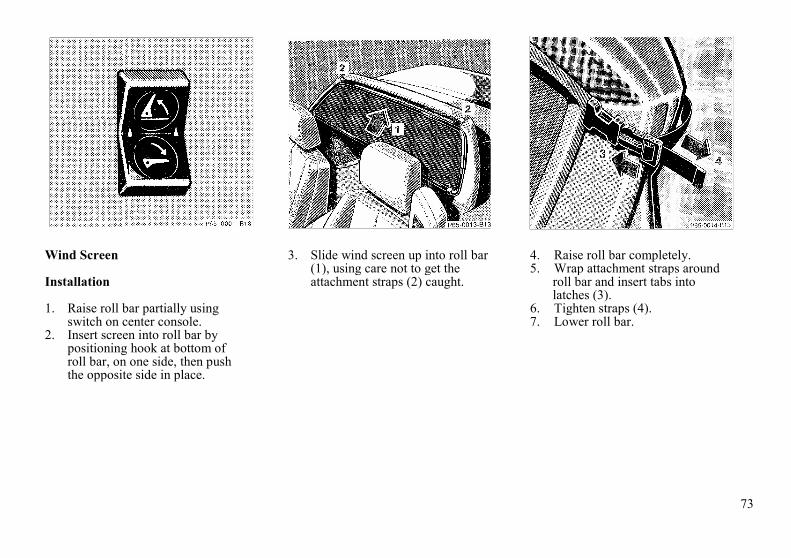
73
Wind Screen
Installation
1. Raise roll bar partially usingswitch on center console.
2. Insert screen into roll bar bypositioning hook at bottom ofroll bar, on one side, then pushthe opposite side in place.
3. Slide wind screen up into roll bar(1), using care not to get theattachment straps (2) caught.
4. Raise roll bar completely.5. Wrap attachment straps around
roll bar and insert tabs intolatches (3).
6. Tighten straps (4).7. Lower roll bar.

74
Setting up
Push top of wind screen fully forwardagainst internal stop
Warning!
The rear storage area should neverbe occupied by passengers since thevehicle is a 2 seater. Furthermore,with the wind screen in place there isa risk of injury, should the roll barbe deployed.
Removal
1. Fold down top of wind screen.2. Raise roll bar using switch on
center console.3. Disconnect attachment strap
latches by squeezing latch.4. Lower roll bar partially
5. Pull wind screen down out of rollbar (5) and lift wind screen out onone side and remove.
Storage
The wind screen can be stored in atrunk mounted container.

75
Antenna
The antenna extends when switchingon the radio and/or telephone.
Note:To retract the antenna (e.g. whenentering a car wash) both radio andtelephone must be switched off.
Cellular Telephone
The vehicle is prepared for theinstallation of a cellular telephone. Forfurther information and installationcontact your authorized Mercedes-Benz dealer.
Warning!
Some jurisdictions prohibit thedriver from using a cellulartelephone while driving a vehicle.Therefore, for safety reasons, thedriver should not use the cellulartelephone while the vehicle is inmotion. Stop the vehicle in a safelocation before answering or placinga call.

76

77
Driving

78
Drinking and Driving
Warning!
Drinking and driving can be a verydangerous combination. Even a smallamount of alcohol or drugs can affectyour reflexes, perceptions andjudgment. The possibility of a seriousor even fatal accident is sharplyincreased when you drink and drive.Please don't drink and drive or allowa friend to drive when he has beendrinking.
Parking Brake
To engage, depress parking brakepedal. With the key in steering lockposition 2, the brake warning lamp inthe instrument cluster should come onbrightly (function check for lamp).To release the parking brake, pullhandle on instrument panel. The brakewarning lamp in the instrument clustershould go out (also see brake warninglamp, page 88).
Driving Off
Test the brakes briefly after drivingoff. Perform this procedure only whenthe road is clear of other traffic.Warm up the engine smoothly. Do notplace full load on the engine until theoperating temperature has beenreached.
Warning!
Keep driver's foot area clear at alltimes. Objects stored in this areamay impair pedal movement.

79
Automatic Transmission
The automatic transmissionselects individual gears auto-matically, dependent upon
• Selector lever position• Accelerator position• Vehicle speed
Important!
When parking the car and beforeworking on the vehicle with the enginerunning, firmly depress the parkingbrake pedal and shift the selector leverinto "P".
Driving
The selector lever is automaticallylocked while in position "P". To movethe selector lever out of position "P",the service brake pedal must be firmlydepressed before the shift lock willrelease.
Shift selector lever to the desiredposition only when the engine is idlingnormally and the service brake isapplied. Do not release the brake untilready to drive. The vehicle mayotherwise start creeping when theselector lever is in drive or reverseposition.
Warning!
It is dangerous to shift the selectorlever out of "P" or "N" if the enginespeed is higher than idle speed. Ifyour foot is not on the brake pedal,the car could accelerate quicklyforward or in reverse. You could losecontrol of the car and hit someone orsomething. Only shift into gear whenthe engine is idling normally andwhen your right foot is firmly on thebrake pedal.
Important!
After selecting any driving positionfrom "N" or "P", wait a moment toallow the gear to fully engage beforeaccelerating, especially when theengine is cold.
Accelerator position
Partial throttle = early upshifting =normal acceleration
Full throttle = later upshifting = rapidacceleration
Kickdown (depressing the acceleratorbeyond full throttle) = downshifting tonext lowest gear = maximumacceleration. Once the desired speed isattained, ease up on the accelerator -the transmission shifts up again.

80
Selector Lever Positions
The automatic gear shifting processcan be adapted to specific operatingconditions using the selector lever.
P Parking lock.The parking lock is an additionalsafeguard to the parking brakewhen parking the vehicle. Engageonly with the car stopped.
Note:The key can be removed from thesteering lock only with the selectorlever in position "P". With the keyremoved, the selector lever islocked in position "P".
R Reverse gear.Shift to reverse gear only with thecar stopped.
N Neutral.No power is transmitted from theengine to the rear axle. When thebrakes are released, the vehicle canbe moved freely (pushed or towed).Do not engage "N" while drivingexcept to coast when the vehicle isin danger of skidding (e.g. on icyroads, see Winter drivingInstructions Index).
Important!
Coasting the vehicle for an ex-tended period of time with selectorlever in "N" can result intransmission damage. That is notcovered by the MERCEDES-BENZ Limited Warranty.
D The transmission automaticallyupshifts to 4th gear. Position "D"provides optimum drivingcharacteristics under all normaloperating conditions.
4 Upshift to 4th gear only. Suitablefor performance driving. To shiftfrom position "D" to "4", pushselector lever to the left.
3 Upshift to 3rd gear only. Suitablefor moderately steep hills. Sincethe transmission does not shifthigher than 3rd gear, this gearselection will allow use of theengine's braking power downhill.
2 Upshift to 2nd gear only. Fordriving in mountainous regions orunder extreme operatingconditions. This gear selectionwill allow use of the engine'sbraking power when descendingsteep grades.
1 In this position, the engine'sbraking effect is utilized byshifting into 1st gear. Use thisposition while descending verysteep or lengthy downgrades andonly at speeds below 40 mph (60km/h).

81
Important!
With selector lever in position "D", "4"or "3", upshifting from 1st to 2nd to 3rdgear is delayed depending on vehiclespeed and engine temperature. Thisallows the catalytic converter to heat upmore quickly to operatingtemperatures.During the brief warm-up period thisdelayed upshift and increased enginenoise might be perceived as amalfunction. However, neither theengine nor transmission are negativelyaffected by this mode of operation.
The delayed upshift is effectivewith vehicle speeds below 31 mph (50km/h) at partial throttle and enginetemperatures below 95°F (35°C).
To avoid overrevving the engine whenthe selector lever is moved to a lowerdriving range, the transmission will notshift to a lower gear as long as thevehicle speed exceeds the speed limitof that gear.
To prevent the engine from laboring atlow RPMs, do not allow the enginespeed to drop too low on uphillgradients.
Depending on the degree of theincline, shift selector lever to a lowergear range early enough to maintainengine RPM within the best torquerange.
Warning!
On slippery road surfaces, neverdownshift in order to obtainbraking action. This could result inrear wheel slip and reduced vehiclecontrol. Your vehicle's ABS will notprevent this type of loss of control.
Maneuvering
To maneuver in tight areas, e.g. whenpulling into parking space, control thecar speed by gradually releasing thebrakes. Accelerate gently and neverabruptly step on the accelerator.
To rock a car out of soft ground (mudor snow), alternately shift fromforward to reverse, while applyingslight partial throttle.
Rocking a car free in this manner maycause the ABS warning lamp to comeon. Turn off and restart the engine toclear the malfunction indication.
Stopping
For brief stops, e.g. at traffic lights,leave the transmission in gear and holdvehicle with the service brake.
For longer stops with the engine idling,shift into "N" or "P".
When stopping the car on an uphillincline, do not hold it with theaccelerator, use the brake. This avoidsunnecessary transmission heat build up.
Warning!
Getting out of your car with theselector lever not fully engaged inposition "P" is dangerous. Whenparked on a steep incline, position"P" alone may not prevent yourvehicle from moving, possibly hittingpeople or objects.Always set the parking brake inaddition to shifting to position "P".When parked on an incline,also turn front wheel against curb.

82
Program Mode Selector SwitchThe transmission is provided with aselector switch for Standard "S" andWinter (snow and ice) "W" programmodes.
Warning!Always be certain of the programmode selected since the vehicledriving characteristics change withthe selection of the program mode.
S Standard modePress switch on symbol "S". Usethis mode for all regular driving.The vehicle starts out in 1stgear.
W Winter (snow and ice) modePress switch on symbol "W". Thevehicle starts out in 2nd gear,except with selector lever in 1stgear, or with accelerator pedal inkick-down position.The "W" mode helps to improvetraction and driving stability of thevehicle.With hard acceleration the upshiftsoccur at lower vehicle and enginespeeds than in the "S" programmode.
Warning!During stops use the brake,especially on an incline, to preventthe vehicle from rolling.
Emergency Operation(Limp Home Mode)If vehicle acceleration worsens, or thetransmission no longer shifts, thetransmission operates in Limp HomeMode. In addition the "CHECKENGINE" malfunction indicator lampin the instrument cluster may come on.In this mode only the 2nd gear orreverse gear can be activated.To engage 2nd gear or reverse:1. Stop the vehicle.2. Move selector lever to
position "P".3. Turn off the engine.4. Wait 10 seconds.5. Restart the engine.6. Move selector lever to
position "D" (for 2nd gear), ormove selector lever to position "R"(for reverse gear).
Have the transmission checked at yourauthorized Mercedes-Benz dealer assoon as possible

83
Cruise ControlAny given speed above approximately25 mph (40 km/h) can be maintainedwith the cruise control by operating thelever.
1. Accelerate and set:Lift lever briefly to set speed. Holdlever up to accelerate.
2. Decelerate and set:Depress lever briefly to setspeed.Hold lever down to decelerate.
Normally the vehicle is accelerated tothe desired speed with the accelerator.
Speed is set by briefly pushing thelever to position 1 or 2. The acceleratorcan be released.
The speed can be increased (e.g. forpassing) by using the accelerator. As"soon as the accelerator is released, thepreviously set speed will be resumedautomatically.
If a set speed is to be increased ordecreased slightly, e.g. to adapt to thetraffic flow, hold lever in position 1 or2 until the desired speed is reached, orbriefly tip the control lever in theappropriate direction for increases ordecreases in 1 km/h (0.6 mph)increments. When the lever is released,the newly set speed remains.
3. CancelingTo cancel the cruise control,briefly push lever to position 3.
When you step on the brake orclutch pedal or the vehicle speeddrops below approx. 35 km/h (22mph), for example when drivingupgrade, the cruise control will becanceled.If the cruise control cancels byitself and remains inoperative untilthe engine is restarted, have thesystem checked at your authorizedMERCEDES-BENZ dealer as soonas possible.
4. ResumeIf the lever is briefly pushed toposition 4 when driving at a speedexceeding approx. 40 km/h (25mph), the vehicle resumes thespeed which was set prior to thecancellation of the cruise control.The last memorized speed iscanceled when the key in thesteering lock is turned to position 1or 0.

84
Note:If the engine does not brake the vehiclesufficiently while driving on adowngrade, the speed you set on thecruise control may be exceeded andyou may have to step on the brakepedal to slow down. As soon as thegrade eases, the cruise controlled speedwill again be maintained as long as thebrakes were not previously applied, orthe lever may be used to resume thepreviously set speed if the brakes wereapplied.
Warning!
Only use the cruise control if thetraffic and weather conditions makeit advisable to travel at a steadyspeed.
• The use of cruise controlcan be dangerous on windingroads or in heavy trafficbecause conditions do notallow safe driving at asteady speed.
• The use of cruise controlcan be dangerous on slipperyroads. Rapid changesin tire adhesion can resultin wheel spin and loss ofcontrol.
The "Resume" function should onlybe operated if the driver is fullyaware of the previously set speed andwishes to resume this particularpreset speed.
Caution!
When driving with the cruise controlengaged, the transmission selectorlever must not be shifted to position"N" as otherwise the engine willoverrev, possibly causing enginedamage that is not covered by theMercedes-Benz Limited Warranty.

85
Charge Indicator Lamp
Should the charge indicator lamp fail tocome on prior to starting when the keyis in steering lock position 2 or shouldit fail to go out after starting or duringoperation, this indicates a fault whichmust be repaired at an authorizedMERCEDES-BENZ dealerimmediately.
If the charge indicator lamp comes onwhile the engine is running, this mayindicate that the poly-V-belt hasbroken. Should this condition occur,the poly-V-belt must be replaced beforecontinuing to operate the vehicle.Otherwise, the engine will overheat dueto an inoperative water pump whichmay result in damage to the engine.
Do not continue to drive the vehiclewith the charge indicator lampilluminated. Doing so could result inengine damage that is not covered bythe Mercedes-Benz Limited Warranty.
Engine Oil Pressure Gauge
The oil pressure at idle speed may dropif the engine is at operatingtemperature. This will not jeopardizethe engine's operational reliability.
Pressure must, however, riseimmediately upon acceleration.
Note:If the oil pressure gauge needle dropsto "0" with the engine running, thendamage to the engine may occur withcontinued operation. Turn off engineimmediately and contact an authorizedMercedes-Benz dealer. Do not operatethe car until the condition is repaired.
Low Engine Oil Level WarningLamp
With the key in steering lock position2, the oil pressure warning lamp comeson and goes out with the enginerunning.
If the warning lamp comes on with theengine running and at operatingtemperature, the engine oil level has
dropped to approximately theminimum mark on the dipstick.When this occurs, the warning lampwill first come on intermittently andthen stay on if the oil level dropsfurther.
If no oil leaks are noted and there isindicated engine oil pressure, continueto drive to the nearest service stationwhere the engine oil should be toppedto the "full" mark on the dipstick withan approved oil.
The low engine oil level warning lightshould not be ignored. Extendeddriving with the light illuminated couldresult in engine damage that is notcovered by the Mercedes-BenzLimited Warranty.
In addition to the warning lamp, theengine oil level should be periodicallychecked with the dipstick, for exampleduring a fuel stop, or before a long trip.See Index.

86
Engine Oil Consumption
Engine oil consumption checks shouldonly be made after the break-in period.During the break-in period, higher oilconsumption may be noticed and isnormal. Frequent driving at highengine speeds results in increasedconsumption.
Fuel Consumption Gauge
While driving, instantaneous fuelconsumption is indicated in miles pergallon (mpg), or in Canada liters per100 kilometers (I/100 km).
With the engine switched off, theneedle reads "0".
Due to system design, maximumconsumption is indicated at idle speed.
Tachometer
Red marking on tachometer:Excessive engine speed.Avoid this engine speed, as it mayresult in engine damage that is notcovered by the Mercedes-Benz LimitedWarranty.For engine protection, the fuel supplyis interrupted if the engine is operatedwithin the red marking.

87
Fuel Reserve Warning Lamp
With the key in steering lock position2, the fuel reserve warning lamp comeson and goes out with the enginerunning.If the warning lamp does not go outafter starting the engine or if it comeson while driving, it indicates that thefuel level is down to the reservequantity of approx. 2.6 gal (10 liters).
Outside Temperature Indicator
The temperature sensor is located in thefront bumper area. Due to its location,the sensor can be affected by road orengine heat during idling or slowdriving. This means that the accuracyof the displayed temperature can onlybe verified by comparison to athermometer placed next to the sensor,not by comparison to external displays(e.g. bank signs, etc.).
Adaptation to ambient temperaturetakes place in steps and depends on theprevailing driving conditions (stop-and-go or moderate, constant driving) andamount of temperature change.
Warning!
The outside temperature indicator isnot designed to serve as an Ice-Warning Device and is therefore un-suitable for that purpose. Indicatedtemperatures just above the freezingpoint do not guarantee that the roadsurface is free of ice.
Coolant Temperature Gauge
If the antifreeze mixture is effective to-22°F (-30°C), the boiling point of thecoolant in the pressurized coolingsystem of your vehicle is approx.266°F (130°C).During severe operating conditions andstop-and-go city traffic, the coolanttemperature may rise close to the redmarking.
The engine should not be operated withthe coolant temperature in the redzone. Doing so may cause seriousengine damage which is not covered bythe Mercedes-Benz Limited Warranty.
Warning!
• Driving when your engine isbadly overheated can cause somefluids which may have leaked intothe engine compartment to catchfire. You could be seriouslyburned. Turn off the engine andget out of the car until it coolsdown.
• Steam from an overheated enginecan cause serious burns and canoccur just by opening the enginehood. Stay away from the engineif you see or hear steam comingfrom it. Turn off the engine anddo not stand near the car until itcools down.

88
Low Engine Coolant LevelWarning Lamp
With the key in steering lock position2, the warning lamp comes on and goesout with the engine running.
If the warning lamp does not go outafter starting the engine, or if it comeson while driving, then the coolant levelhas dropped below the required level.If no leaks are noticeable and theengine temperature does not increase,continue to drive to the nearest servicestation and have coolant added to thecoolant system. (see Index).
The low engine coolant level warninglight should not be ignored. Extendeddriving with the light illuminated maycause serious engine damage notcovered by the Mercedes-Benz LimitedWarranty.
In cases of major or frequent minorcoolant loss, have the cooling systemchecked at your authorizedMERCEDES-BENZ dealer as soon aspossible.
Note:Do not drive without coolant in thecooling system. The engine canoverheat causing major engine damage.
Monitor the coolant temperature gaugewhile driving.
Warning!
Do not spill antifreeze on hot engineparts. Antifreeze contains ethyleneglycol which may burn if it comesinto contact with hot engine parts.You can be seriously burned.
Low Windshield and HeadlampWasher Fluid Level Warning Lamp
With the key in steering lock position2, the warning lamp comes on andgoes out with the engine running.
If the warning lamp comes on with theengine running, the level of thereservoir has dropped to approx. 1/4 ofthe total volume. The reservoir shouldbe refilled with MB WindshieldWasher Concentrate "S" and water (orcommercially available premixedwindshield washer solvent/antifreeze,depending on ambient temperature -see Index) at the next opportunity. Thereservoir for the windshield andheadlamp washer system is located inthe engine compartment.

89
Roll Bar Warning Lamp
With the key in steering lock position2, the warning lamp comes on and goesout with the engine running.
Warning!
If the warning lamp does not go outafter starting the engine, or if itcomes on while driving, and theindicator lamps in the roll bar switchblink simultaneously, then the rollbar system is defective and may notactivate in an accident. In this case,raise the roll bar manually (seeIndex) before continuing to drive.
Have the roll bar system checked atyour authorized MERCEDES-BENZdealer as soon as possible.
Seat Belt and Backrest LockWarning Lamp
With the key in steering lock position2, the warning lamp comes on and anaudible warning sounds for a shorttime if the driver's seat belt is notfastened.
If a backrest is not engaged in its lock,an audible warning will soundintermittently for up to approx. 20seconds.
After starting the engine, the warninglamp blinks for a brief period toremind the driver and passenger tofasten seat belts before driving off.
If the warning lamp does not go putafter blinking briefly, but is instead litcontinuously, then a backrest is notengaged in its lock.
The warning lamp goes out as soon asthe backrest is engaged in its lock.
If the backrest is locked and thewarning lamp does not go out, havethe system checked at your authorizedMERCEDES-BENZ dealer as soon aspossible.
Exterior Lamp Failure IndicatorLamp
With the key in steering lock position2, a dim indicator lamp comes on, andgoes out with the engine running.
With the key in steering lock position 2or with the engine running, a brightillumination of this lamp indicates anexterior lamp failure (except highmounted stop lamp).
If an exterior lamp fails, the indicatorlamp will come on only when thatlamp is switched on.
If a brake lamp fails, the lamp failureindicator will come on when applyingthe brake and stay on until the engineis turned off.
Note:The indicator lamp will also come on ifan incorrect bulb is installed.
If additional lighting equipment isinstalled (e.g. auxiliary headlamps etc.)be certain to connect into the fusebefore the failure indicator monitoringunit in order to avoid damaging thesystem.

90
Brake Pad Wear Indicator Lamp
The brake pad wear indicator lamp inthe instrument cluster comes on whenthe key in the steering lock is turned toposition 2 and goes out when theengine is running.
If the indicator lamp lights up duringbraking, this indicates that the frontwheel brake pads are worn down(vehicles equipped with ASR frontand/or rear wheel brake pads).
Have the brake system checked at yourauthorized MERCEDES-BENZ dealeras soon as possible.
Brake Warning Lamp
The brake warning lamp will come on:
• when there is insufficient brakefluid in the reservoir (enginerunning and parking brakereleased)
• when the parking brake is set(engine running)
When the minimum mark on thereservoir is reached, have the brakesystem checked for brake pad thicknessand leaks.
To test the brake warning lamp, turnthe key in steering lock to position 2.The brake warning lamp comes on, andshould go out when the engine isrunning.
Warning!
Driving with the brake warninglamp on can result in an accident.Have your brake system checkedimmediately if the brake warninglamp stays on. Don't add brake fluidbefore checking the brake system.Overfilling the brake fluid reservoircan result in spilling brake fluid onhot engine parts and the brake fluidcatching fire. You can be seriouslyburned.

91
Antilock Brake System (ABS)
Important!
The ABS improves steering control ofthe vehicle during braking maneuvers.For maximum benefit, do not pump thebrake pedal, rather use firm, steadybrake pedal pressure.
The ABS prevents the wheels fromlocking up above a vehicle speed ofapproximately 5 mph (8 km/h)independent of road surface conditions.
At the instant one of the wheels isabout to lock up, a slight pulsation canbe felt in the brake pedal, indicatingthat the ABS is in the regulating mode.
On slippery road surfaces, the ABSwill respond even with only slightbrake pedal pressure. The pulsatingbrake pedal can be an indication ofhazardous road conditions andfunctions as a reminder to take extracare while driving.
ABS Control
The ABS malfunction indicator lampin the instrument cluster comes on withthe key in steering lock position 2 andshould go out with the engine running.if the charging voltage falls below 10volts, the malfunction indicator lampcomes on and the ABS is switched off.When the voltage is above this valueagain, the malfunction indicator lampshould go out and the ABS isoperational.
With the ABS malfunctioning, theASR or ESP, if vehicle so equipped,are also switched off. Both malfunctionindicator lamps come on with theengine running.
If the ABS malfunction Indicator lampdoes not go out or comes on whiledriving, it indicates that the ABS hasdetected a malfunction and hasswitched off. In this case, the brakesystem functions in the usual manner,but without antilock assistance.Have the system checked at yourauthorized Mercedes-Benz dealer assoon as possible.
Warning!
Even the ABS cannot prevent thenatural laws of physics from actingon the vehicle. The ABS cannotprevent accidents, including thoseresulting from excessive speed inturns, following another vehicle tooclosely, or aquaplaning. Only a safe,attentive, and skillful driver canprevent accidents. The capabilities ofan ABS equipped car must never beexploited in a reckless or dangerousmanner which could jeopardize theuser's safety or the safety of others.
Notes:
To alert following vehicles to slipperyroad conditions you discover, operateyour hazard warning flashers asappropriate.

92
Acceleration Slip Regulation (ASR)
The acceleration slip regulation willengage at all vehicle speeds, if one orboth drive wheels begin to lose tractionand spin due to excessive acceleration.While engaged, the yellow warninglamp in the speedometer flashes.
With the acceleration slip regulationengaged, the brake is applied to thespinning drive wheel until it regainssufficient traction. If both drive wheelslose traction and spin, the brake isapplied to both drive wheels andsimultaneously, engine torque islimited, to improve the vehicle'sdriving stability.
As traction on the road surfaceincreases, the allowable engine torquealso increases again and the brake is nolonger applied to drive wheels.
Important!
If the ASR warning lamp flashes, adaptyour speed and driving to theprevailing road conditions.
Caution!
If the vehicle is towed with the frontaxle raised (see Towing the vehicle inIndex), the engine must be shut off.Otherwise, the acceleration slipregulation will immediately be engagedand will apply the rear wheel brakes.
Notes:With the key in steering lock position2, the yellow malfunction indicatorlamp in the instrument cluster and theyellow ASR warning lamp in thespeedometer dial come on. They mustgo out when the engine is running.
If the ASR malfunction indicator lampcomes on with the engine running, amalfunction has been detected.Pressing the accelerator pedal willrequire greater effort. Only partialengine output is available.
Have the ASR checked at yourauthorized Mercedes-Benz dealer assoon as possible.
With the ABS malfunctioning, theASR is also switched off.Driving the vehicle with varied sizetires will cause the wheels to rotate atdifferent speeds, therefore theacceleration slip regulation mayactivate (yellow ASR malfunctionindicator lamp in instrument clustercomes on). For this reason, all wheels,including the spare wheel, must havethe same tire size.
When testing the parking brake on abrake test dynamometer, the enginemust be shut off. Otherwise, theacceleration slip regulation willimmediately be engaged and will applythe rear wheel brakes.
In winter operation, the maximumeffectiveness of the acceleration slipregulation is only achieved withMercedes-Benz recommended M + Sradial-ply tires and/or snow chains.

93
ASR control switch located in centerconsole
ASR Control Switch
To improve the vehicle's traction whendriving with snow chains, or startingoff in deep snow, sand or gravel, pressthe upper half of the ASR switch. TheASR warning lamp, located in thespeedometer dial, is continuouslyilluminated.
With the ASR system switched off, theengine torque reduction feature iscancelled. Therefore, the enhancedvehicle stability offered by ASR isunavailable.
Adapt your speed and driving to theprevailing road conditions.A portion of the ASR system remainsactive, even with the switch in the OFFposition.
If one drive wheel loses traction andbegins to spin, the brake is applieduntil the wheel regains sufficienttraction. The traction control engagesat vehicle speeds up to approximately24 mph (40 km/h), and switches off at50 mph (80 km/h).
The ASR warning lamp, located in thespeedometer dial, starts to flash at anyvehicle speed as soon as the tires losetraction and the wheels begin to spin.To switch off: press lower half of theswitch (the ASR warning lamp in thespeedometer dial goes out).
Important!
If the ASR warning lamp flashes:
• during take-off, apply as littlethrottle as possible,
• while driving, ease up on theaccelerator.

94
Electronic Stability Program(ESP)
The ESP enhances directional controland improves traction of the vehicleunder any driving condition.
Over/understeering of the vehicle iscounteracted by applying brakes to theleft or right side wheels. The ESPwarning lamp, located in thespeedometer dial, starts to flash.
Important!
If the ESP warning lamp flashes, adaptyour speed and driving to theprevailing road conditions.
Caution!
If the vehicle is towed with the frontaxle raised (see Towing the vehicle inIndex), the key must not be in steeringlock position 2. Otherwise, theelectronic stability program willimmediately be engaged and will applythe rear wheel brakes.
Notes:
With the key in steering lock position2, the yellow ESP and EPCmalfunction indicator lamps in theinstrument cluster and the yellowwarning lamp in the speedometer dialcome on. They must go out when theengine is running.
If the ESP or EPC malfunctionindicator lamp comes on with theengine running, a malfunction has beendetected. It is possible that now onlypartial engine output is available.
Have the ESP checked at yourauthorized Mercedes-Benz dealer assoon as possible.
With the ABS malfunctioning, the ESPis also switched off.
Driving the vehicle with varied sizetires will cause the wheels to rotate atdifferent speeds, therefore theelectronic stability program mayactivate (yellow ESP malfunctionindicator lamp in instrument clustercomes on). For this reason, all wheels,including the spare wheel, must havethe same tire size.
When testing the parking brake on abrake test dynamometer, the enginemust be shut off. Otherwise, theelectronic stability program willimmediately be engaged and will applythe rear wheel brakes.
In winter operation, the maximumeffectiveness of the electronic stabilityprogram is only achieved withMercedes-Benz recommended M + Sradial-ply tires and/or snow chains.

95
ESP control switch located in centerconsole
ESP Control Switch
To improve the vehicle's traction whendriving with snow chains, or startingoff in deep snow, sand or gravel, pressthe upper half of the ESP switch. TheESP warning lamp, located in thespeedometer dial, is continuouslyilluminated.
With the ESP system switched off, theengine torque reduction feature iscancelled. Therefore, the enhancedvehicle stability offered by ESP isunavailable.
Adapt your speed and driving to theprevailing road conditions.A portion of the ESP system remainsactive, even with the switch in the OFFposition.
If one drive wheel loses traction andbegins to spin, the brake is applieduntil the wheel regains sufficienttraction. The traction control engagesat vehicle speeds up to approximately24 mph (40 km/h), and switches off at50 mph (80 km/h).
The ESP warning lamp, located in thespeedometer dial, starts to flash at anyvehicle speed as soon as the tires losetraction and the wheels begin to spin.
To switch off: press lower half of theswitch (the ESP warning lamp in thespeedometer dial goes out).
Important!
If the ESP warning lamp flashes:
• during take-off, apply as littlethrottle as possible,
• while driving, ease up on theaccelerator.

96
Adaptive Damping System(ADS)
Depending upon road surfaceconditions, load, driving style, ADSwill automatically adjust the optimalride firmness.
The malfunction indicator lamp comeson with the key in steering lockposition 2 and goes out when theengine is running.
If the malfunction indicator lamp stayson after the engine is running or comeson while driving, then the system hasdetected a malfunction.
We recommend that you visit anauthorized Mercedes-Benz dealer assoon as possible to have the systemchecked-out.
Note:If the power supply was interrupted(battery disconnected or empty), themalfunction indicator lamp will lightup when the engine is running.Turn the steering wheel from full left tofull right lock position. The lightshould go out.
Adaptive Damping SystemAdjustment
The switch is located in the centerconsole.
1. Firm dampening program.This setting should be used forsporty driving.During the setting for sportydriving the indicator lamp in theswitch lights up.
2. Soft dampening program.This setting should be used forregular driving.

97
Level Control System
The switch is located next to theexterior lamp switch.
1. Level control switch2. Wheel change switch
Level Control Switch Positions
Press upper half of switch once forOption 1. One indicator lamp lights up.Press upper half of switch twice forOption 2. Both indicator lamps light up.
Note:
The indicator lamps blink at first, andstay on continuously once the selectedlevel is attained.
Press lower half of switch once:From Option 2, system switches toOption 1. Only one indicator lamp isilluminated.
From Option 1, system returns toNormal Level. Indicator lamp goes out.
Press lower half of switch twice:
From Option 2, system returns toNormal Level. Both indicator lamps goout.
Normal Level
Used for normal operation of thevehicle.
At speeds above approximately 60 mph(95 km/h) the vehicle chassis islowered automatically by about onehalf inch (15 mm).
Option 1Level increases one half inch(15 mm)
This setting may be used when roadsurface conditions are rough.
When Option 1 is selected, the vehiclechassis is raised by one half inch (15mm) at vehicle speeds up to approx. 35mph (60 km/h).
At speeds between approximately 35mph (60 km/h) and 60 mph (95 km/h)the vehicle chassis is lowered to itsnormal level.
At speeds above approximately 60 mph(95 km/h) the vehicle chassis islowered an additional one half inch(15 mm).
Notes:When exceeding approximately 60mph (95 km/h), the system switchesfrom Option 1 back to Normal Level.The indicator lamp will go out.If speed exceeds 35 mph (60 km/h) butdoes not exceed 60 mph (95 km/h), thevehicle chassis will be automaticallyraised again by one half inch (15 mm)when vehicle speed drops belowapprox. 35 mph (60 km/h).

98
Option 2Level increases one inch (30 mm)
This setting may be used when roadsurface conditions are very rough forincreased ground clearance.
Upon selection of Option 2 the vehiclechassis is raised by 1 inch (30 mm).This option can only be selected atvehicle standstill, and the raised level isonly retained up to speeds ofapproximately 15 mph (25 km/h).
At speeds between approximately 15mph (25 km/h) and 35 mph (60 km/h)the vehicle chassis is lowered by onehalf inch (15 mm).
At speeds between approximately 35mph (60 km/h) and 60 mph (95 km/h)the vehicle chassis is lowered to itsnormal level.
At speeds above approximately 60 mph(95 km/h) the vehicle chassis islowered an additional one half inch(15 mm).
Notes:When exceeding approximately 35mph (60 km/h), the system will switchfrom Option 2 to Option 1. Only oneindicator lamp will be illuminated.
When exceeding approximately 60mph (95 km/h) the system will switchfrom Option 1 to Normal Level. Theindicator lamp will go out.
If speed exceeds approx. 35 mph (60km/h) but does not exceed 60 mph (95km/h), the system will switch fromOption 2 to Option 1 when vehiclespeeds drop below approximately 35mph (60 km/h).
If speed does not exceed 35 mph (60km/h), the system will switch fromOption 2 to Option 1 when driving onafter the vehicle has been stopped.
Wheel Change Switch (2)
Prior to changing a wheel, depresswheel change switch with enginerunning. The switch and ADS indicatorlamps light up. The presently selectedlevel option cannot be changed now.After activating the safety switch stopthe engine.
Warning!
Do not drive the vehicle while thewheel change switch is activatedsince the vehicle suspension will notfunction properly.

99
Emission Control
Certain systems of the engine serve tokeep the toxic components of theexhaust gases within permissible limitsrequired by law.
These systems, of course, will functionproperly only when maintained strictlyaccording to factory specifications.Any adjustments on the engine should,therefore, be carried out only byqualified MERCEDES-BENZtechnicians. Engine adjustments shouldnot be altered in any way. Moreover,the specified service and maintenancejobs must be carried out regularlyaccording to MERCEDES-BENZservicing requirements. For detailsrefer to the Maintenance Booklet.
Warning!
Inhalation of exhaust gas ishazardous to your health. Allexhaust gas contains carbonmonoxide, and inhaling it can causeunconsciousness and lead to death.Do not run the engine in confinedareas (such as a garage) which arenot properly ventilated. If you thinkthat exhaust gas fumes are enteringthe vehicle while driving, have thecause determined and corrected im-mediately. If you must drive underthese conditions, drive only with atleast one window fully open.
On-Board Diagnostic System
The Sequential Multiport FuelInjection (SFI) control modulemonitors emission control componentsthat either provide input signals to orreceive output signals from the controlmodule. Malfunctions resulting frominterruptions or failure of any of thesecomponents are indicated by the"CHECK ENGINE" malfunctionindicator lamp in the instrument clusterand are simultaneously stored in theSFI control module.
If the "CHECK ENGINE" malfunctionindicator lamp comes on, have thesystem checked at your authorizedMercedes-Benz dealer as soon aspossible.
An on-board diagnostic connectorallows the accurate identification ofsystem malfunctions through thereadout of diagnostic trouble codes.
Connector location:SL 320 - passenger compartment, nearthe accelerator pedal. SL 500, SL 600 -engine compartment, on firewall.

100
Winter Driving
Have your car winterized at yourauthorized MERCEDES-BENZ dealerbefore the onset of winter.
• Change the engine oil if the enginecontains an oil which is notapproved for winter operation. Forviscosity (SAE class) and fillingquantity, see "Fuels, Coolants,Lubricants, etc." see Index.
• Check engine coolantanticorrosion/antifreezeconcentration.
• Additive for the windshield washerand headlamp cleaning system: AddMB Concentrate "S" to a premixedwindshield washersolvent/antifreeze which isformulated for below freezingtemperatures (see Index).
• Test battery: Battery capacity dropswith decreasing ambienttemperature. A well charged batteryensures that the engine can alwaysbe started, even at low ambienttemperatures.
• Tires: We recommend M + S radialtires on all four wheels for thewinter season. Observe permissiblemaximum speed for M + S radialtires and the legal speed limit.
Note:
In winter operation, the maximumeffectiveness of the electronic stabilityprogram, of the acceleration slipregulation or of the electronic tractionsystem can only be achieved with M +S radial-ply tires and/or snow chainsrecommended by Mercedes-Benz.
Snow Chains
Use only snow chains that are testedand recommended by Mercedes-Benz.Your authorized Mercedes-Benz dealerwill be glad to advise you on thissubject.
Chains should only be used on the rearwheels. Follow the manufacturer'smounting instructions.
Snow chains should only be driven onsnow covered roads at speeds not toexceed 30 mph (50 km/h).
Remove chains as soon as possiblewhen driving on roads without snow.
For tips on driving on slipperywinter roads, refer to Index.
Vehicles with Acceleration SlipRegulation (ASR) or ElectronicStability Program (ESP):
When driving with snow chains, pressthe ASR control switch or the ESPcontrol switch, refer to Index.
Vehicles withAMG Sport Package
Use of snow chains is not permissiblewith tire sizes 245/40 ZR18 or 275/35ZR18.
Traveling Abroad
Abroad, there is a widely-spreadMercedes-Benz service network atyour disposal. If you plan to travel intoareas which are not listed in the indexof your dealer directory, you shouldrequest pertinent information fromyour authorized Mercedes-Benz dealer.
S

101
Practical Hints

102
Hood
To open:To unlock the hood, pull release lever(1) under the driver's side of theinstrument panel.
Important!
To avoid damage to the windshieldwipers or hood, open the hood onlywith wipers in the parked position.
Pull handle (2) out of radiator grill tostop, and open hood. Do not lift hoodat louvers of grill! Make certain thewindshield wiper arm is not foldedforward.
To close:Lower hood and let it drop into lockfrom a height of approx. 1 ft (30 cm),assisting with flat hands placed only onedges of hood (3).
To avoid hood damage, if hood isnot fully closed, re-open and repeatclosing procedure.
Warning!
To help prevent personal injury,stay clear of moving parts when thehood is open and the engine isrunning. Be sure the hood isproperly closed before driving.
The engine is equipped with atransistorized ignition system.Because of the high voltage it isdangerous to touch any components(ignition coil, distributor, spark plugsockets, ignition cables, diagnosticsocket) of the ignition system:
• with the engine running,
• while starting the engine,
• if the ignition is "on" and theengine is turned manually.
We recommend that you do not openthe hood, if you see flames or smokecoming from the enginecompartment.

103
Example
Checking Coolant Level
The coolant level can be checkedvisually at the transparent coolantreservoir.To check the coolant level, the vehiclemust be parked on level ground.
Check coolant level only when coolantis cold:The coolant should reach the rib in thefiller neck. Also see marking (1) onreservoir.
Warning!
• Use extreme caution whenopening the hood if there are anysigns of steam or coolant leakingfrom the cooling system.
• Do not remove pressure cap oncoolant reservoir if enginetemperature is above 90°C(194°F). Allow engine to cooldown before removing cap. Thecoolant reservoir contains hotfluid and is under pressure.
• Using a rag, turn cap to firstnotch to relieve excess pressure.If opened immediately, hotscalding fluid and steam will beblown out under pressure,possibly causing personal injury,
• Do not spill antifreeze on hotengine parts. Antifreeze containsethylene glycol which may burn ifit comes into contact with hotengine parts. You can beseriously burned.
Adding Coolant
If coolant has to be added, a 50/50mixture of water and MBanticorrosion/antifreeze should beadded.
SL 320:The drain plugs for the coolingsystem are located on the right sideof the engine block and at the bottomof the radiator.
SL 500, SL 600:The drain plugs for the coolingsystem are located on the right andleft sides of the engine block and atthe bottom of the radiator.
Anticorrosion/antifreeze, seeCoolants in Index.
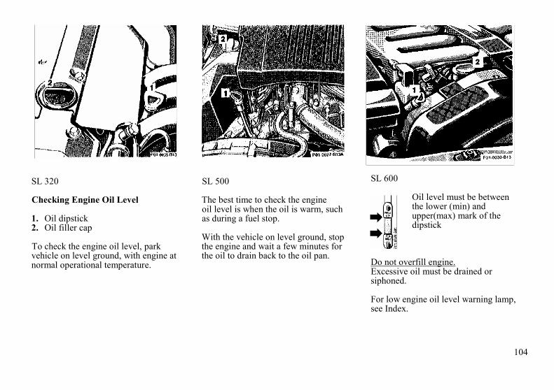
104
SL 320
Checking Engine Oil Level
1. Oil dipstick2. Oil filler cap
To check the engine oil level, parkvehicle on level ground, with engine atnormal operational temperature.
SL 500
The best time to check the engineoil level is when the oil is warm, suchas during a fuel stop.
With the vehicle on level ground, stopthe engine and wait a few minutes forthe oil to drain back to the oil pan.
SL 600
Oil level must be betweenthe lower (min) andupper(max) mark of thedipstick
Do not overfill engine.Excessive oil must be drained orsiphoned.
For low engine oil level warning lamp,see Index.

105
Automatic Transmission Fluid Level
The transmission has a permanent fill ofautomatic transmission fluid.Regular automatic transmission fluidlevel checks and changes are notrequired. For this reason the dipstick isomitted.
If you notice fluid leaks or gear shiftingmalfunctions, have your authorizedMercedes-Benz dealer check thetransmission fluid level.
Trunk Lamp
1. Switching off2. Switching on
Switch off trunk lamp if the trunk is toremain open for a long period of time.This prevents the vehicle battery frombeing discharged.
When the trunk lid is closed, theswitch will reset and turn on the lampthe next time the lid is opened.

106
First Aid Kit
The first aid kit is located in the left trunkwell.
Stowing Things in the Vehicle
Warning!
To help avoid personal injury during acollision or sudden maneuver, exercisecare when stowing things. Put luggageor cargo in the trunk if possible. Do notpile luggage or cargo higher than theseat backs.
Vehicle ToolsThe vehicle tools are located below thejack.
Spare Wheel
1. Trunk floor2. Strap
Roll back the floor mat, lift the trunkfloor (1) and engage strap (2) in thehooks on the upper edge of the trunklid.
First remove the vehicle jack, then thespare wheel; reinstall in reverse order.

107
Vehicle Jack
1. Jack arm2. Jack base3. Tool kit
See illustration for proper storage ofjack.Before storing the jack, the jack arm(1) must be lowered almost to the base(2) of the jack.
Note:First remove the vehicle jack, then thespare wheel; reinstall in reverse order.
Warning!
The jack is designed exclusively forjacking up the vehicle at the jacktubes built into either side of thevehicle. Use the jack only to lift thevehicle during a wheel change. Neverget beneath the vehicle while it issupported by the jack. Keep handsand feet away from the area underthe lifted vehicle. Always firmly setparking brake and block wheelsbefore raising vehicle with jack.
Do not disengage parking brakewhile the vehicle is raised. Be certainthat the jack is always vertical whenin use, especially on hills. Always tryto use the jack on level surface. Besure that the jack arm is fullyinserted in the jack tube. Alwayslower the vehicle onto sufficientcapacity jackstands before workingunder the vehicle.
Wheels
Replace rims or tires with the samedesignation, manufacturer and type asshown on the original part. See yourauthorized MERCEDES-BENZ dealerfor further information.
Warning!
Do not mix different tire con-struction types (i.e. radial, bias, andbias-belted) on your car becausehandling may be adversely affectedand may result in loss of control.
See your authorized MERCEDES-BENZ dealer for information on testedand recommended rims and tires forsummer and winter operation. Theycan also offer advice concerning tireservice and purchase.

108
Tire Replacement
Front tires should be replaced in sets.Furthermore - in the event of tirereplacement - the spare wheel, ifpossible, should be used on the rearaxle. Rims and tires must be of thesame size. For dimensions, see"Technical Data".
We recommend that you break in newtires for approx. 100 km (60 miles) atmoderate speed. It is imperative thatthe wheel mounting bolts beretightened after approx. 100 to 500 km(60 -300 miles).
On new vehicles retightening is carriedout during the 1st inspection.Retightening is also necessarywhenever wheels are fitted, e.g. whenthe spare wheel is used for the firsttime or when a set of wheels with M +8 tires is installed.
Tightening torque: 110 Nm(80 ft. lb.)".
For rim and tire specifications, refer to“Technical Data”.
Warning!
Worn, old tires can cause accidents.If the tire tread is badly worn, or ifthe tires have sustained damage,replace them.
When replacing rims, use onlygenuine MERCEDES-BENZ wheelbolts (identified by Mercedes star)specified for the rim type. Failure todo so can result in the bolts loosen-ing and possibly an accident
Rotating Wheels
The wheels can be rotated according tothe degree of tire wear while retainingthe same direction of travel.
Rotating, however, should be carriedout at the scheduled maintenanceintervals, before the characteristic tirewear pattern (shoulder wear on frontwheels and tread center wear on rearwheels) becomes visible, as otherwisethe driving properties deteriorate.
Important!
Unidirectional snow tires must alwaysbe mounted with arrow on tire sidewallpointing in direction of vehicle forwardmovement.
Note:Thoroughly clean the inner side of thewheels any time you rotate the wheelsor wash the vehicle underside.
The use of retread tires is notrecommended. Retread tires mayadversely affect the handlingcharacteristics and safety of thevehicle.Dented or bent rims cause tire pressureloss and damage to the tire beads. Forthis reason, check rims for damage atregular intervals.
The rim flanges must be checked forwear before a tire is mounted.Remove burrs, if any.
Check and correct tire inflationpressure after rotating the wheels. ForTire Inflation Pressure refer to Index

109
Warning!
The jack is designed exclusively forjacking up the vehicle at the jacktubes built into either side of thevehicle. Use the jack only to lift thevehicle during a wheel change. Neverget beneath the vehicle while it issupported by the jack. Keep handsand feet away from the area underthe lifted vehicle. Always firmly setparking brake and block wheelsbefore raising vehicle with jack.
Do not disengage parking brakewhile the vehicle is raised. Be certainthat the jack is always vertical whenin use, especially on hills. Always tryto use the jack on level surface. Besure that the jack arm is fullyinserted in the jack tube. Alwayslower the vehicle onto sufficientcapacity jackstands before workingunder the vehicle.
Spare Wheel forAMG Sport Package Version
The spare wheel rim size is8 J x 16 H2.
In the case of a flat tire or breakdown,you may temporarily use an 8 J x 16H2 wheel rim, when observingfollowing instructions:
• Do not exceed vehicle speed of50 mph (80 km/h).
• Drive to the nearest repairfacility.
For additional information, refer to"Technical Data".
Changing Wheels
Warning!
Before working on the vehicle, e.g.when changing wheels, the roll barshould be raised with the switch, andthe key be removed from the steeringlock, to prevent possible injury.
Move vehicle to a level area which is asafe distance from the roadway.
1. Firmly set parking brake, raiseroll bar, and turn on hazardwarning flasher.
2. Move selector lever toposition "P".
3. While engine is running,depress wheel change switchfor level control. The switch andADS indicator lamps light up.
4. Turn off engine.

110
3. Prevent vehicle from rollingaway by blocking wheels withwheel chocks (not supplied withvehicle) or sizable wood blockor stone. When changing awheel on a hill, place chockson the downhill side blockingboth wheels of the other axle.On a level road, place onechock in front of and one behind the wheel that is diagonallyopposite to the wheelbeing changed.
4. Using lug wrench, loosen butdo not yet remove the wheelbolts.
5. Remove the protective cover fromthe jack support tube opening byinserting a screwdriver in theopening and prying it out.
The tube openings are locateddirectly behind the front wheelhousings and in front of the rearwheel housings.
6. Insert jack arm fully into thetube hole up to the stop.Position the jack so that it isalways vertical (plumb-line) asseen from the side (see arrow),even if the vehicle is parked onan incline.
7. Jack up the vehicle until thewheel is clear of the ground.Never start engine while vehicleis raised.
8. Unscrew upper-most wheel boltand install alignment bolt (1)supplied in the tool kit. Removethe remaining bolts. Keep boltthreads protected from dirt andsand.
9. Remove wheel. Grip wheel fromsides. Keep hands from beneaththe wheels.

111
10. Clean contact surfaces ofwheel and wheel hub. Installspare wheel on wheel hub.Insert wheel bolts and tightenthem slightly.
To avoid paint damage, placewheel flat against hub and hold itthere while installing first wheelbolt.Unscrew the alignment bolt (1) toinstall the last wheel bolt.
11. Lower car. Remove jack andinsert jack tube cover.
Before storing the jack, the jack armmust be lowered almost to the base
of the jack. Store the spare wheel firstand then the vehicle jack.
Warning!
Always replace wheel bolts that aredamaged or rusted.
Never apply oil or grease to wheelbolts.Damaged wheel hub threads shouldbe repaired immediately.Incorrect mounting bolts orimproperly tightened mounting boltscan cause the wheel to come off. Thiscould cause an accident. Be sure touse the correct mounting bolts.
Important!
When installing new wheels themounting bolts must be retightenedafter approx. 60 - 300 miles (100-500km).
12. Fold wrench together and tightenthe five bolts evenly, following thesequence illustrated above, until allbolts are tight.
Observe a tightening torque of80 ft. lb. (110 Nm).
13. Correct tire pressure.
14. Depress wheel change switchfor level control. The switchand ADS indicator lamps willgo out.
Warning!
Do not drive the vehicle while thewheel change switch is activatedsince the vehicle suspension will notfunction properly.

112
Tire Inflation Pressure
A table (see fuel filler flap) lists the tireinflation pressures specified forMercedes Benz recommended tires aswell as for the varying operatingconditions.
Important!
Tire pressure differs by approx. 1.5 psi(0.1 bar) per 18°F (10°C) of airtemperature change. Keep this in mindwhen checking tire pressure inside agarage - especially in the winter.
Example:
If garage temperature =approx. + 68 ° F (+ 20 ° C) andambient temperature =approx. + 32° F (0°C) then the adjustedair pressure = specifiedair pressure + 3 psi (+ 0.2 bar).
Tire pressures listed for light loads areminimum values offering high drivingcomfort.
Increased inflation pressures for heavyloads produce favorable handlingcharacteristics with lighter loads andare perfectly permissible. The ride ofthe vehicle, however, will becomesomewhat harder.
Tire temperature and pressure increasewith the vehicle speed. Tire pressureshould therefore only be corrected oncold tires. Correct tire pressure in warmtires only if pressure has dropped be-low the pressure listed in the table andthe respective operating conditions aretaken into consideration.
An underinflated tire due to a slowleak (e.g. due to a nail in the tire) maycause damage such as tread separation,bulging etc.. Regular tire pressurechecks (including the spare tire) atintervals of no more than 14 days aretherefore essential.
If a tire constantly loses air, it shouldbe inspected for damage
Warning!
Do not overinflate tires, overinflatingtires can result in sudden deflation(blowout) because they are morelikely to become punctured ordamaged by road debris, potholesetc.. Follow recommended inflationpressures.
Do not overload the tires byexceeding the specified vehiclecapacity weight (as indicated by thelabel on the driver's door latch post).Overloading the tires can overheatthem, possibly causing a blowout.

113
Battery
Warning!
Failure to follow theseinstructions can result in severeinjury or death.Never lean over batteries whileconnecting, you might get injured.
Battery fluid contains sulfuric acid.Do not allow this fluid to come incontact with eyes, skin or clothing. Incase it does, immediately flushaffected area with water and seekmedical help if necessary.
A battery will also produce hydrogengas, which is flammable andexplosive. Keep flames or sparksaway from battery, avoid improperconnection of jumper cables,smoking etc..
The maintenance-free battery is locatedin the trunk under the right-hand wheelwell cover panel.The service life of the battery isdependent on its condition of charge.The battery should always be keptsufficiently charged, in order to last anoptimum length of time.
Therefore, we strongly recommendthat you have the battery chargechecked frequently, and corrected ifnecessary, especially if you use thevehicle less than approximately 200miles (300 km) per month, mostly forshort distance trips, or if it is notused for long periods of time.
Only charge a battery with a batterycharger after the battery has beendisconnected from the vehicleelectrical circuit.
Always disconnect the battery negativelead first and connect last.When removing and connecting thebattery, always make sure that allelectrical consumers are off and thekey is in steering lock position 0. Thebattery and its vent tube must alwaysbe securely installed when the car is inoperation.
While the engine is running the batteryterminal clamps must not be loosenedor detached, otherwise the generatorand other electronic components wouldbe damaged.
Important!
Do not close a door with the windowsfully closed while the power supply isinterrupted (battery disconnected orempty). Doing so could damage thewindow frame.
Note:
After reconnecting the battery alsoresynchronize the Express feature ofthe power windows and the AdaptiveDamping System (ADS) (see PowerWindows and ADS in Index),
Battery Recycling
Batteries contain materials that canharm the environment withimproper disposal.Large 12 Volt storage batteriescontain lead.
Recycling of batteries is thepreferred method of disposal.
Many states require sellers of batteriesto accept old batteries for recycling.

114
Exterior Lamps
Headlamp Adjustment
Correct headlamp adjustment isextremely important. Check andreadjust headlamps at regular intervalsand when a bulb has been replaced.
Headlamp Assembly
1. Headlamp horizontal adjustmentscrew
2. Headlamp vertical adjustmentscrew
3. High and low beam headlampcover
4. Squeeze latches for high andlow beam headlamp cover
5. Turn signal, parking, sidemarker and standing lamp bulb
6. Electrical connector for highand low beam headlamp bulb
7. Clamping ring for high and lowbeam headlamp bulb

115
Replacing Bulbs
When replacing bulbs, install only 12volt bulbs with the specified wattrating.
When replacing halogen bulbs do nottouch glass portion of bulb with barehands. Use plain paper or a clean cloth.
Warning!
Halogen lamps contain pressurizedgas. A bulb can explode if you
• touch or move it when hot,• drop the bulb,• scratch the bulb.
Bulb for High and Low Beam(Halogen type 9004)
Open hood.
Squeeze latches (4) and remove cover(3) upwards. Pull off electricalconnector (6). Turn clamping ring (7)counterclockwise and pull out bulbtogether with clamping ring. Removebulb.
Insert new bulb (flat side facing up),mount clamping ring (7) (with tabfacing down) and turn clockwise. Pushelectrical connector on securely.
Turn Signal, Parking, SideMarker and Standing Lamp(2375 NA [28.5/8.3 W/ 30/2.2cp] bulb)
Open hood.
Turn bulb socket (5) with bulbcounterclockwise and pull out. Pushbulb into socket, turn counterclockwiseand remove.
Insert new bulb in socket, push in andtwist clockwise. Reinstall bulb socket,push in and twist clockwise.

116
Headlamp Assembly (Xenon)
1. Headlamp horizontal adjustmentscrew
2. Headlamp vertical adjustmentscrew
3. Adjuster for horizontaladjustment scale
4. Cover for low beam headlamp
5. Latch for cover (4)
6. Cover for high beam headlamp
7. Latch for cover (6)
8. Turn signal, parking, sidemarker and standing lamp bulb
9. Electrical connector for highbeam headlamp bulb

117
Replacing Bulbs
When replacing bulbs, install only 12volt bulbs with the specified wattrating.
When replacing halogen bulbs do nottouch glass portion of bulb with barehands. Use plain paper or a clean cloth.
Warning!
Halogen lamps contain pressurizedgas. A bulb can explode if you
• touch or move it when hot,• drop the bulb,• scratch the bulb.
Bulb for Low Beam (Xenon)
Warning!
Because of high voltage in Xenonlamps, it is dangerous to replace thebulb or repair the lamp and itscomponents. We recommend thatyou have such work done by aqualified technician.
Bulb for High Beam H1 (55 W)
Open hood.
Depress latch (7) and removecover (6).
Pull off electrical connector (9).
Unhook clamping ring and removebulb.
Insert new bulb (seating properly incutouts of bulb socket), and mountclamping ring. Reinstall and pushelectrical connector on securely.
Reinstall bottom end of cover (6) andpush against top end of cover untilproperly seated.
Check lamp for proper operation.
Turn Signal, Parking, SideMarker and Standing Lamp
(2375 NA [28.5/8.3 W/30/2.2 cp] bulb)
Open hood.
Turn bulb socket (5) with bulbcounterclockwise and pull out. Pushbulb into socket, turn counterclockwiseand remove.
Insert new bulb in socket, push in andtwist clockwise. Reinstall bulb socket,push in and twist clockwise.

118
Adjusting Headlamp
Correct headlamp adjustment isextremely important. To check andreadjust a headlamp, follow steps 1through 7. Please note:
• Adjustments to low beamsimultaneously aim the high beam.
• Vehicle should have a normaltrunk load.
• Vertical aim adjustmentschange horizontal aim.
1. Park vehicle on level surfaceapproximately 6 inches(152 mm) from a vertical testscreen or wall. The centerlineof the vehicle must be at a 90°angle to the test screen.
2. Using a "T" square and acarpenter's level, align andmark a vertical centerline (8) onthe test screen using the outerreference point (low beam)found on each headlamp lens.As a check, the distancebetween centerlines should be49 5/8 inches (1260 mm).
3. Move vehicle on the levelsurface 25 feet (7.6 m) straightback from the wall.
4. Open hood
5. Turn key in steering lock toposition 2.
6. Vertical headlamp aim(low beams on):Turn adjusting screw (2) (coun-terclockwise to adjust headlampdownward, clockwise upward)until bubble in the level (6) iscentered on the "0" mark.
Graduations: 0.18° pitch.
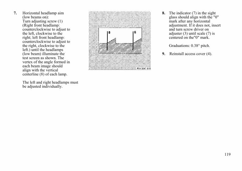
119
7. Horizontal headlamp aim(low beams on):Turn adjusting screw (1)(Right front headlamp:counterclockwise to adjust tothe left, clockwise to theright; left front headlamp:counterclockwise to adjust tothe right, clockwise to theleft.) until the headlamps(low beam) illuminate thetest screen as shown. Thevertex of the angle formed ineach beam image shouldalign with the verticalcenterline (8) of each lamp.
The left and right headlamps mustbe adjusted individually.
8. The indicator (7) in the sightglass should align with the "0"mark after any horizontaladjustment. If it does not, insertand turn screw driver onadjuster (3) until scale (7) iscentered on the"0" mark.
Graduations: 0.38° pitch.
9. Reinstall access cover (4).

120
Taillamp Assemblies
1. Side marker lamp(10 W/6 cp bulb)
2. Turn signal lamp(21/4 W/35/1.2 cp bulb)
3. Tail, parking and standing lamp(21 W/32 cp bulb)
Driver's side:Tail, parking, standing and rearfog lamp (21/4W/35/1.2cp bulb)
4. Backup lamp(21 W/32 cp bulb)
5. Stop lamp(21 W/32 cp bulb)
To replace bulbs:
Push the locking button (1) on the rearof the lamp support inward and swingopen lamp support. Push down the bulbto be changed, turn to the left andremove.
License Plate Lamps(5 W bulb)
Loosen both securing screws (1),remove lamp and take out bulb.

121
Fuses
In engine compartment:
1. Main fuse box
In trunk on rear wall:
2. Auxiliary fuse box
Before replacing a blown fuse,determine the cause of the short circuit.
Spare fuses are supplied inside the fusebox. Observe amperage and color offuse.
Always use a new fuse forreplacement. Never attempt to repair orbridge a blown fuse.
After replacing a blown fuse, close fusebox cover.

122
All except Sport Package
Towing the Vehicle
The rear towing eye is located at theright, below the bumper. The fronttowing eye is located on the passengerside behind a flap in the bumper panel.
Cover removal for all except SportPackage version: Insert finger in recessof flap and pull flap but.
Cover removal for Sport Packageversion: Pull cover away from bumper.
Sport Package
Cover installation for all except SportPackage version: Engage cover atbottom and press in top securely.
Cover installation for Sport Packageversion: Engage cover end (rightarrow), end press cover end (leftarrow) securely.
We recommend that the vehicle betransported using flat bed equipment.This method is preferable to othertypes of towing.The vehicle may be towed with all ofthe wheels on the ground and theselector lever in position "N" fordistances up to 30 miles (50 km) andat a speed not to exceed 30 mph (50km/h).To positively avoid a possibility ofdamage to the transmission, however,we recommend to disconnect the driveshaft at the rear axle drive flange onany towing beyond a short tow to anearby garage.Do not tow with sling-type equipment.Towing with sling-type equipmentover bumpy roads will damageradiator and supports.The use of wheel lift equipment willdamage engine oil pan.
Important!
When transporting vehicle on flat bedequipment, the front end of the vehiclemust be loaded first. Additionalramping may be required for loadingto protect bumper fascia.

123
Warning!
With the engine not running, thereis no power assistance for thebraking and steering systems. Inthis case, it is important to keep inmind that a considerably higherdegree of effort is necessary to brakeand steer the vehicle.
Note:To signal turns while being towed withhazard warning flasher in use, turn keyin steering lock to position 2 andactivate combination switch for left orright turn signal in usual manner - onlythe selected turn signal.
Upon canceling the turn signal, thehazard warning flasher will operateagain.
Jump Starting
Warning!
Failure to follow these directions willcause damage to the electroniccomponents, and can lead to abattery explosion and personalinjury.
Never lean over batteries whileconnecting or jump starting, youmight get injured.
Battery fluid contains sulfuric acid.Do not allow this fluid to come incontact with eyes, skin or clothing. Incase it does, immediately flushaffected area with water, and seekmedical help if necessary.
A battery will also produce hydrogengas, which is flammable and veryexplosive. Keep flames or sparksaway from battery, avoid improperconnection of jumper cables,smoking etc..
Read all instructions beforeproceeding.
If the battery is discharged, the engineshould be started with jumper cablesand the (12 V) battery of anothervehicle.
The battery is located in the trunkbehind the right-hand cover panel.
Proceed as follows:
1. Position the vehicle with thecharged battery so that thejumper cables will reach, butnever let the vehicles touch.Make sure the jumper cables donot have loose or missinginsulation.
2. On both vehicles:
• Turn off engine and all lightsand accessories, except hazardflashers or work lights.
• Apply parking brake and shiftselector lever to position "P".

124
Important!
3. Clamp one end of the firstjumper cable to the positive (+)terminal of the discharged batteryand the other end to the positive(+) terminal of the charged battery.Make sure the cable clamps do nottouch any other metal parts.
4. Clamp one end of the secondjumper cable to the groundednegative (-) terminal of thecharged battery and the finalconnection to the negative (-)terminal of the dischargedbattery.
Important!
5. Start engine of the vehicle withthe charged battery arid run athigh idle". Make sure the jumpercables are not near pulleys,fans, or other parts that willmove when the engine isstarted. Then start engine of thedisabled vehicle in the usualmanner.
6. After the engine has started,remove jumper cables by exactlyreversing the above installationsequence, starting with the lastconnection made first. Whenremoving each clamp, make surethat it does not touch any othermetal while the other end is stillattached.
Important!
A discharged battery can freeze atapprox. + 14°F (-10°C). In that case, itmust be thawed out before jumpercables are used. A frozen battery canexplode and cause personal injury.
Jumper cable specifications:
• Minimum cable cross-section of25 mm2 or approx. 2 AWG
• Maximum length of 3500 mm(11.5ft).
Manual Release of Fuel Filler Flap
In case of malfunction, the fuel fillerflap can be opened manually. Pull themanual release knob (1) behind theright trunk panel while simultaneouslyopening the fuel filler flap.
Ski Rack
Use only our approved ski rack toavoid damage to the vehicle. Followmanufacturer's installation instructions.

125
Testing Infrared Remote ControlChecking Batteries:
If the transmit button (1) is pressedlonger than 1 second, the batteryindicator lamp in the transmitter eye(2) briefly illuminates -indicating thatthe batteries are in order.Change batteries if the indicator lampdoes not come on.
Changing Batteries:
Unfold key from holder by pressinglock button (3). Pull off battery cover(4).
Change batteries, inserting new onesunder contact spring (5) with plus (+)side facing up.
Press battery cover onto housing untillocked in place.
Important!
Batteries contain materials that canharm the environment if disposed ofimproperly. Recycling of batteries isthe preferred method of disposal. Fordisposal, please follow manufacturer'srecommendation on battery package.Replacement battery: Lithium, type CR2025 or equivalent.
Synchronizing System:
The system may have to be re-synchronized, if the transmitter iswithout voltage for several minutes.
To synchronize system, aim transmittereye (2) at inside rear view mirrorreceiver and briefly press transmitbutton (1) twice. Within approx. 30seconds, insert key in steering lock andturn it to position 2.
The infrared remote control shouldonce again be operational.

126
Raising Soft Top Manually
In case of malfunction, the power softtop can also be raised manually. Thisprocedure should be performed withgreat care by 2 persons.
A combination open-end/ Allen-headwrench in the vehicle tool kit isrequired for this job.
1. Open doors or lower windows.2. Lower roll bar with roll bar
switch. If the roll bar cannot belowered, the soft top can becarefully guided over the rollbar.
3. For safety reasons fromsteering lock.
Warning!
Do not place your hands near the rollbar, soft top frame, upper windshieldarea or soft top storage compartmentwhile the soft top is being locked.Serious personal injury may occur.
4. Unlock left and right soft topstorage compartment locks: Placeopen-end wrench on bolt betweenroll bar and storage compartmentcover. Turn wrench towards rearof car (1).
Open storage compartment coverand place in upright position (2).
5. Pull soft top (3) together with softtop bow (4) out of compartment.
6. Pull soft top bow (4) out ofcompartment.

127
7. Place soft top frame (5) ontowindshield header.
8. Place soft top bow (4) in itsvertical position.
9. Pivot sun visors to side.Remove left and right caps (6).
10. Using Allen-head wrench, lock leftand right of soft top frame (5) towindshield header - turn wrench in3 stages towards center of car:
1. Left lock to first notch2. Right lock to second notch3. Left lock to second notch.

128
11. Close storage compartmentcover (2). - Lock storagecompartment lock on right side:Place open-end wrench onbolt between roll bar andstorage compartment cover.Turn wrench towards front ofcar (7).
12. Lower soft top bow (4).The rearsection of the soft top cannot belocked during manual operation.
Note:Have the soft top operation checked atyour authorized Mercedes-Benz dealeras soon as possible.
Spare Parts Service
All authorized Mercedes-Benz dealersmaintain a stock of original spare partsrequired for maintenance and repairwork. In addition, strategically locatedparts distribution centers provide quickand reliable parts service.
More than 300,000 different spare parts,even for older models, are available.Mercedes-Benz original spare parts aresubjected to the most stringent qualityinspections. Each part has beenspecifically developed, manufacturedor selected for and adapted toMercedes-Benz vehicles.
Therefore, Mercedes-Benz originalspare parts should be installed.

129
SL 320
Layout of Poly-V-Belt Drive
1. Automatic belt tensioner
2. Crankshaft
3. Air conditioning compressor
SL 500
4. Fan
5. SL 500: Idler pulleySL 600: Air pump
6. Generator (alternator)
7. Idler pulley
SL 600
8. Power steering pump
9. Coolant pump
For dimensions of the poly-V seeTechnical Data in Index

130
Replacing Wiper Blades
For safety reasons, remove keyfrom steering lock before replacingwiper blade, otherwise the motor cansuddenly turn on and cause injury.
Windshield Wiper Blade
Removal:
Fold wiper arm forward. Press safetytab down (1), push wiper bladedownward (2) and remove.
Installation:
Press down safety tab of new wiperblade. Insert wiper blade between thetabs (3) on the wiper arm. Then presssafety tab upward until it locks inplace.
Note:Do not open engine hood with wiperarm folded forward.
Do not allow the wiper arm to contactthe windshield glass without a wiperblade inserted. The glass may bescratched or broken.
Make certain that the wiper blade isproperly installed. An improperlyinstalled blade may cause windshielddamage.
Headlamp Wiper Blades(except xenon lamps)
Removal:
Fold wiper arm forward. Press safetytab (1) down and remove wiper bladeat guide pin (2, arrow).
Installation:
Press safety tab (1) down and insert theguide pin (2) into the wiper arm.Release safety tab, the wiper bladeengages.

131
Cleaning and Care of the Vehicle
Warning!
Many cleaning products can behazardous. Some are poisonous,others are flammable. Always followthe instructions on the particularcontainer. Always open your car'sdoors or windows when cleaning theinside.Never use fluids or solvents that arenot designed for cleaning your car.
In operation, your vehicle is subjectedto varying external influences which, ifgone unchecked, can attack the paint-work as well as the underbody andcause lasting damage.
Such damage is caused not only byextreme and varying climaticconditions, but also by air pollution,road salt, tar, gravel and stonechipping. Grease and oil, fuel, coolant,brake fluid, bird droppings, tree resins,etc. should be removed immediately to
avoid paint damage. Frequentwashing, however, reduces and/oreliminates the aggressiveness andpotency of the above adverse in-fluences.
More frequent washings are necessaryto deal with unfavorable conditions; forexample, near the ocean, in industrialareas (smoke, exhaust emissions), orduring winter operation.
You should check your vehicle fromtime to time for stone chipping or otherdamage. Any damage should berepaired as soon as possible to preventthe start of corrosion.
In doing so, do not neglect theunderside of the car. A prerequisite fora thorough check is a washing of theunderbody followed by a thoroughinspection. Damaged areas need to bereundercoated.
Your vehicle has been treated at thefactory with a wax-base rustproofing inthe body cavities which will fast for thelifetime of the vehicle. Post-productiontreatment is neither
necessary nor recommended byMERCEDES-BENZ because of thepossibility of incompatibility betweenmaterials used in the productionprocess and others applied later.
We have selected car-care products andcompiled recommendations which arespecially matched to our vehicles andwhich always reflect the latest techno-logy. You can obtain MB car-careproducts at your authorizedMERCEDES-BENZ dealer.
Scratches, corrosive deposits, corrosionor damage due to negligent or incorrectcare cannot always be removed orrepaired with the car-care products re-commended here. In such cases it isbest to seek aid at your authorizedMERCEDES-BENZ dealer.
The following topics deal with thecleaning and care of your vehicle andgive important "how-to" information aswell as references to recommendedMB car-care products.
Additional information can be found inthe booklet titled "Car Care".

132
Engine Cleaning
Prior to cleaning the enginecompartment make sure to protectelectrical components and connectorsfrom the intrusion of water or cleaningagents.
Corrosion protection, such as MBAnticorrosion Wax should be appliedto the engine compartment after everyengine cleaning. Before applying, allcontrol linkage bushing should belubricated. The poly-V-belt and allpulleys should be protected from anywax.
Car Washing
Before washing your vehicle, removeinsect residues, MB Insect Remover isrecommended. Do not use hot water orwash your car in direct sunlight. Useonly a mild car wash detergent, such asMB Autoshampoo.
Thoroughly spray the car with adiffused jet of water. Direct only a veryweak spray towards the ventilationintake. Use plenty of water and rinsethe sponge and chamois frequently.
Rinse with clear water and thoroughlywipe dry with a chamois. Do not allowcleaning agents to dry on the finish.
If the vehicle has been run through anautomatic car wash - in particular oneof the older installations - rewipe therecessed sections in the taillamps(designed to prevent soiling) ifnecessary. No solvents (fuels, thinnersetc.) must be used.
In the winter, thoroughly remove alltraces of road salt as soon aspossible.When washing the underbody, do notforget to clean the inner sides of thewheels.
Tar Stains
Quickly remove tar stains before theydry and become more difficult toremove. MB Tar Remover isrecommended.
Window Cleaning
Use a window cleaning solution on allglass surfaces. MB Glass Cleaner isrecommended.
Wiper Blade
Clean the wiper blade rubber with aclean cloth and detergent solution.Replace blade twice a year; oncebefore and once after winter.
Headlamp Cleaning System
The condition of the wiper blades isimportant for satisfactory cleaning ofthe headlamp lenses. We thereforerecommend that the blades beinspected regularly.
Replace damaged wiper blades.
Seat Belts
The webbing must not be treated withchemical cleaning agents. Use onlyclear, lukewarm water and soap. Donot dry the webbing at temperaturesabove 176°F (8Q°C) or in directsunlight.
Warning!
Do not bleach or dye seat belts asthis may severely weaken them. In acrash they may not be able toprovide adequate protection.

133
Instrument Cluster
Use a gentle dish-washing detergent ormild detergent for delicate fabrics as awashing solution. Wipe with a clothmoistened in lukewarm solution. Donot use scouring agents.
Steering Wheel and GearShift Lever
Wipe with a damp cloth and drythoroughly or clean with MB LeatherCleaner.
Upholstery
Using aftermarket seat covers orwearing clothing that have thetendency to give off coloring (e.g.when wet etc.) may cause theupholstery to become permanentlydiscolored. By lining the seats with aproper intermediate cover, contact-discoloration will be prevented.
Wipe leather upholstery with a dampcloth and dry thoroughly or clean withMB Leather Cleaner. Exerciseparticular care when cleaningperforated leather as its undersideshould not become wet.
Plastic Parts, Headlinerand Rubber Parts
Do not use oil or wax on these parts.See separate subjects for additionalinformation.
Paintwork, Painted BodyComponents
MB-Paint Protector and Sealer shouldbe applied when water drops on thepaint surface do not "bead up";normally in 3 to 5 months dependingon climate and washing detergent used.
MB-Paint-Polish should be applied ifpaint surface shows signs of dirtembedding (i.e. loss of gloss).
MB-Fine Polishing Paste must be usedwhen the paint surface shows signs ofexcessive fading/ chalking due to lackof care etc..
Do not apply any of these products orwax if your car is parked in the sun orif the hood is still hot.
Use the appropriate MB-Touch-UpStick for quick and provisional repairsof minor paint damage (i.e. chips fromstones, car doors etc.).
Automatic Antenna
For trouble-free operation of theautomatic antenna, we recommend thatyou clean the antenna mastperiodically.
Light Alloy Wheels
Mercedes-Benz approved Wheel Careshould be used for regular cleaning ofthe light alloy wheels.
If possible, clean wheels once a weekwith Mercedes-Benz approved WheelCare, using a soft bristle brush and astrong spray of water.
Follow instructions on container.
Note:Use only acid-free cleaning materials.The acid could lead to corrosion.
134
Soft Top
Clean soft top with soft top raised andlocked. Lower the soft top into thestorage compartment only if the top iscompletely dry. If the top is kept in thestorage compartment for a lengthyperiod, raise it and air it out with thewindows down about every 4 months.
Dry cleaning:
Brush top (always from front to rear)with a soft-bristled brush.
Wet cleaning:
Brush the dry top. Wash with a milddetergent and an ample supply oflukewarm water by wiping with a soft-bristled brush or sponge from front torear. Then rinse thoroughly with clearwater.
If only parts of the top have beenwashed, wet the entire top and allow itto air-dry before lowering it into thestorage compartment.Wipe the rear window with a clothsoaked with a mild, non-abrasivedetergent, rinse and rub dry.
Do not use sharp-edged instruments forthe removal of ice and snow.
Note:Never run the vehicle through anautomatic car wash with the soft top inplace as you may damage the soft topmaterial.
Remove bird droppings immediately.The organic acid damages the materialand causes the soft top to leak.
In general, regular spraying orcleansing with clear water is sufficientto keep the top clean.
Wash the top only when heavily soiled.
Caution!
Never use any gasoline, thinner, tar andstain removers, glass cleaner, or similarorganic solvents to clean the soft top,plastic window or wind screen.They will cause damage which is notcovered by the Mercedes-Benz -Limited Warranty.
Ornamental Moldings
For regular cleaning and care of verydirty chrome-plated parts, use a chromecleaner.
Wind Screen
Use only water or mild detergent toclean the wind screen.
Hard Plastic Trim Items
Pour MB Plastic Cleaner onto soft lint-free cloth and apply with lightpressure.
Headliner
Soft top:Clean with soft bristle brush, or use adry-shampoo cleaner in case ofexcessive dirt.

135
Technical Data

136
1. Certification Tag(left door pillar)
2. Identification Tag(left window post)
3. Vehicle Identification No.4. Engine No.
(SL 320 right front,SL 600 right rear)
5. Body No. and Paint No.6. Emission Control Tag7. Information Tag
California versionVacuum line routing foremission control system
Identification Plates
When ordering spare parts,please specify vehicle identification and engine numbers.

137
Vehicle Data Card
The vehicle data card contains allimportant data pertaining to thevehicle. It should be kept in themaintenance booklet where indicated,and it is needed when obtainingreplacement or additional keys at yourauthorized Mercedes-Benz dealer.
Warranty Coverage
Your car is covered under the terms ofthe "warranties" printed in the Owner'sService and Warranty Policy Bookletand your authorized MERCEDES-BENZ dealer will exchange or repairany defective parts in accordance withthe terms of the following warranties:
1. New vehicle limited warranty
2. Emission systems warranty
3. Emission performance warranty
4. California emission controlsystems warranty.
Loss of Owner's Service andWarranty Policy
Should you lose your Owner's Serviceand Warranty Policy Booklet, haveyour authorized MERCEDES-BENZdealer arrange for a replacement. It willbe mailed to you.

138
Technical Data 320 SL Rims – Tires (expect Sport Package)Model SL 320 (129 063)1 Rims (light alloy rims) 8J x 16 H 2
Wheel offset 34 mm (1.3 in)Engine 104 Summer tires:Mode of operation 4-stroke engine, Radial-ply tires 225/55 ZR 16
gasoline injection Winter tires:No. of cylinders 6 Radial-ply tires 225/55 R 16 93 T M+SBore 89.90 mm (3.54 in) 225/55 R 16 93 H M+SStroke 84.00 mm (3.30 in)Total piston displacement 3199 m³ (195.2 cu.in) Rims - Summer Tires (Sport Package)Compression ratio 10 RimsOutput acc.to SAE J 1349 170 kW/5600rpm Front axle
(228 hp/5600 rpm) AMG light alloy rims 8J x 18 H 2Maximum torque acc. to SAE J 1349 315 Nm/3750 rpm Wheel offset 31 mm (1.2 in)
(232 ft-lb/3750 rpm) Rear axleMaximum engine speed 6400 rpm AMG light alloy rims 9J x 18 H 2Firing order 1-5-3-6-2-4 Wheel offset 35 mm (1.4 in)Poly – V belts length 2205 mm
Radial-ply tires1 The quoted data apply only to the standard vehicle. Front axle 245/40 ZR 18 ²
See an authorized Mercedes-Benz dealer for the Rear axle 275/35 ZR 18 ²corresponding data of all special bodies and specialequipment. Spare Wheel
Rims (light alloy) 8J x 16 H 2² Must not be used with snow chains. Wheel offset 34 mm (1.3 in)
Summer tires:
Radial-ply tires 225/55 ZR 16

139
Technical Data SL 320
Electrical System Weights See certification tagGenerator (alternator) 14 V/110 A Hardtop load max. 30 kg (66 lb)
Starter motor 12 V/1.7KW Trunk load max. 100 kg (220 lb)
Battery 12 V/100 Ah Main Dimensions
Overall vehicle length 4500 mm (177.2 in)Spark plugs
Electrode gap
Bosch F 9 DCOBeru 14 F-9 DUOChampion C 12 YCC
Overall vehicle width 1812 mm (71.3 in)
Tightening torque 0.032 in (0.8 mm) Overall height 1303 mm (51.3 in)
Wheel base 2515 mm (99.0 in)Track, front 1535 mm (60.4 in)Track, rear 1523 mm (60.0 in)

140
Technical Data SL 500 Rims – Tires (expect Sport Package)Model SL 500 (129 067)1 Rims (light alloy rims) 8J x 16 H 2
Wheel offset 34 mm (1.3 in)Engine 119 Summer tires:Mode of operation 4-stroke engine, Radial-ply tires 225/55 ZR 16
gasoline injection Winter tires:No. of cylinders 8 Radial-ply tires 225/55 R 16 93 T M+SBore 96.50 mm (3.80 in) 225/55 R 16 93 H M+SStroke 85.00 mm (3.35 in)Total piston displacement 4973 m³ (303.5 cu.in) Rims - Summer Tires (Sport Package)Compression ratio 10 RimsOutput acc.to SAE J 1349 235 kW/5600rpm Front axle
(315 hp/5600 rpm) AMG light alloy rims 8J x 18 H 2Maximum torque acc. to SAE J 1349 470 Nm/3900 rpm Wheel offset 31 mm (1.2 in)
(347 ft-lb/3900 rpm) Rear axleMaximum engine speed 6000 rpm AMG light alloy rims 9J x 18 H 2Firing order 1-5-4-8-6-3-7-2 Wheel offset 35 mm (1.4 in)Poly – V belts length 2510 mm Radial-ply tires
Front axle: 245/40 ZR 18 ²1 The quoted data apply only to the standard vehicle. Rear axle 275/35 ZR 18 ²
See an authorized Mercedes-Benz dealer for thecorresponding data of all special bodies and special Spare Wheelequipment.
Rim light alloy 8J x 16 H 2² Must not be used with snow chains. Wheel offset 34 mm (1.33 in)
Summer tireRadial-ply tires 225/55 ZR 16

141
Technical Data SL 500
Electrical System Weights See certification tag
Generator (alternator) 14 V/143 A Hardtop load max. 30 kg (66 lb)Starter motor 12 V/1.8 KW Trunk load max. 100 kg (220 lb)Battery 12 V/100 AhSpark plugs Bosch F 9 DCO Main Dimensions
Beru 14 F-9 DUOChampion C 12 YCC Overall vehicle length 4500 mm (177.2 in)
Electrode gap 0.032 in (0.8 mm) Overall vehicle width 1812 mm ( 71.3 in)Tightening torque 15-22 ft. lb. (20-30 Nm) Overall height: 1303 mm ( 51.3 in)
Wheel base 2515 mm ( 99.0 in)Track, front 1535 mm ( 60.4 in)Track, rear 1523 mm ( 60.0 in)

142
Technical Data SL 600 Rims – Tires (expect Sport Package)Model SL 600 (129 076)1 Rims (light alloy rims) 8J x 16 H 2
Wheel offset 34 mm (1.3 in)Engine 120 Summer tires:Mode of operation 4-stroke engine, Radial-ply tires 225/55 ZR 16
gasoline injection Winter tires:No. of cylinders 12 Radial-ply tires 225/55 R 16 93 T M+SBore 89.00 mm (3.50 in) 225/55 R 16 93 H M+SStroke 80.20 mm (3.16 in) Rims - Summer Tires (Sport Package)Total piston displacement 5987 m³ (365.4 cu.in) RimsCompression ratio 10 Front axleOutput acc.to SAE J 1349 290 kW/5200rpm AMG light alloy rims 8J x 18 H 2
(389 hp/5200 rpm) Wheel offset 31 mm (1.2 in)Maximum torque acc. to SAE J 1349 570 Nm/3800 rpm Rear axle
(420 ft-lb/3800 rpm) AMG light alloy rims 9J x 18 H 2Maximum engine speed 6000 rpmFiring order 1-12-5-8-3-10-6-7-2-
11-4-9Poly – V - belts length 2585 mm
Rear axle
Spare WheelRims (light alloy) 8J x 18 H 2Wheel offset 34 mm (1.2 in)
1 The quoted data apply only to the standard vehicle.See an authorized Mercedes-Benz dealer for thecorresponding data of all special bodies and specialequipment.
Summer tire² Must not be used with snow chains. Radial-ply tires 225/55 ZR 16

143
Technical Data SL 600Weights See certification tag
Electrical SystemHardtop load max. 30 kg ( 66 lb)
Generator (alternator) 14 V/143 A Trunk load max. 100 kg (220 lb)Starter motor 12 V/2.2KWBattery 12 V/100 Ah Main DimensionsSpark plugs Bosch F 9 DCO
Beru 14 F-9 DUO Overall vehicle length 4499 mm (177.1 in)Champion C 12 YCC Overall vehicle width 1812 mm ( 71.3 in)
Electrode gap 0.8 mm (0.032 in) Overall height 1303 mm ( 51.3 in)Tightening torque 15-22ft.lb (20-30 Nm) Wheel base 2515 mm ( 99.0 in)
Track, front 1535 mm ( 60.4 in)Track, rear 1523 mm ( 60.0 in)
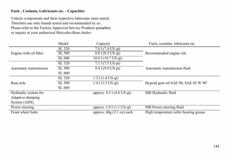
144
Fuels , Coolants, Lubricants etc. - Capacities
Vehicle components and their respective lubricants must match.Therefore use only brands tested and recommended by us.Please refer to the Factory Approved Service Products pamphlet,or inquire at your authorized Mercedes-Benz dealer.
Model Capacity Fuels, coolants, lubricants etc.SL 320 7.0 l (7.4 US qt)
Engine with oil filter SL 500 8.0 l (8.5 US qt) Recommended engine oilsSL 600 10.0 l (10.7 US qt)SL 320 7.1 l (7.5 US pt)
Automatic transmission SL 500 9.4 l (9.9 US pt) Automatic transmission fluidSL 600SL 320 1.3 l (1.4 US qt)
Rear axle SL 500 1.4 l (1.5 US qt) Hypoid gear oil SAE 90, SAE 85 W 901
SL 600Hydraulic system for approx. 4.5 l (4.8 US qt) MB Hydraulic fluidAdaptive dampingSystem (ADS)Power steering approx. 1.0 l (1.1 US qt) MB Power steering fluidFront wheel hubs approx. 60g (2.1 oz) each High temperature roller bearing grease

145
Model Capacity Fuels, coolants, lubricants etc.
Accelerator controllinkage
Hydraulic fluid
Brake system approx. 0.5 US qt (0.5 I) MB Brake fluid (DOT 4)Windshield washer and approx. 5.3 US qt (5.0 I) MB Windshield washer concentrate "S"1
headlamp cleaning systemSL 320 approx. 12.2 US qt (11.5 I) MB Anticorrosion/antifreeze
Cooling system SL 500 approx. 16.4 US qt (15.5 I)SL 500 approx. 16.4 US qt (15.5 I)
Fuel tank approx. 21.1 US gal (80 I) Premium unleaded gasoline: Postedincluding a reserve of approx. 2.6 US gal (10 I) Octane 91 (Average of 96 RON/86 MON)Air conditioner system R-134a refrigerant and special
lubricant(Never R-12)
1 Use MB Windshield Washer Concentrate “S” and water for temperatures above freezing or MB Windshield WasherConcentrate “S” and commercially available premixed windshield washer solvent/antifreeze for temperatures belowfreezing. Follow suggested mixing ratios, see Windshield/Headlamp Washer System in Index.

146
Engine Oils
Engine oils are specifically tested fortheir suitability in our engines.Therefore, use only engine oilsrecommended by Mercedes-Benz.Information on recommended brands isavailable at your authorized Mercedes-Benz dealer.
Engine Oil Additives
Do not blend oil additives with engineoil. They may be harmful to the engineoperation.
Damage or malfunctions resulting fromblending oil additives are not coveredby the Mercedes-Benz LimitedWarranty.
Air Conditioner Refrigerant
Ozone-friendly HFC-134a refrigerantand special lubricating oil is used in theair conditioner system.Never use R-12 (CFG) or mineral-based lubricating oil, otherwise damageto the system will occur.
Brake Fluid
During vehicle operation, the boilingpoint of the brake fluid is continuouslyreduced through the absorption ofmoisture from the atmosphere. Underextremely hard operating conditions,this moisture content can lead to theformation of bubbles in the system thusreducing the system's efficiency.
The brake fluid must therefore bereplaced every two years, preferablyin the spring.
It is recommended to use only brakefluid approved by Mercedes Benz.Your authorized Mercedes-Benz dealerwill provide you with additionalinformation.
Premium Unleaded Gasoline
Caution!
To maintain the engine's durability andperformance, premium unleadedgasoline must be used. If premiumunleaded is not available and lowoctane fuel is used, follow theseprecautions:
• have the fuel tank filled onlypartially with unleaded regularand fill up with premium unleaded as soon as possible,
• avoid full throttle driving andabrupt acceleration,
• do not exceed an engine speedof 3000 rpm, if the vehicle isloaded with a light load such astwo persons and no luggage,
• do not exceed 2/3 of maximumaccelerator pedal position, if thevehicle is fully loaded or operatingin mountainous terrain.

147
Fuel Requirements
Use only Premium unleaded meetingASTM standard D 439:
The octane number (posted at thepump) must be 91min. It is an averageof both, the Research (R) octanenumber and the Motor (M) octanenumber: [(R + M)/2]. This is alsoknown as ANTI-KNOCK INDEX.
Unleaded gasoline containingoxygenates such as Ethanol, IPA, IBAand TBA can be used provided theratio of any one of these oxygenates togasoline does not exceed 10%, MTBEnot to exceed 15%.
The ratio of Methanol to gasoline mustnot exceed 3% plus additionalcosolvents.
Using mixtures of Ethanol andMethanol is not allowed. Gasohol,which contains 10% Ethanol and 90%unleaded gasoline, can be used.
These blends must also meet all otherfuel requirements such as resistance tospark knock, boiling range, vaporpressure etc..
Gasoline Additives
A major concern among enginemanufacturers is carbon build upcaused by gasoline. Mercedes-Benzrecommends to use only qualitygasoline containing additives thatprevent the build up of carbon deposits.
After an extended period of using fuelswithout such additives, carbon depositscan build up especially on the intakevalves and in the combustion area,leading to engine performanceproblems such as:
• warm-up hesitation,• unstable idle,• knocking/pinging,• misfire,• power loss.
Do not blend other specific fueladditives with fuel. They only result inunnecessary cost, and may be harmfulto the engine operation.
Damages or malfunctions resultingfrom poor fuel quality or from blendingspecific fuel additives are not coveredby the Mercedes-Benz LimitedWarranty.

148
Therefore the following product isstrongly recommended for use in yourcar: Mercedes-BenzAnticorrosion/Antifreeze Agent.
Before the start of the winter season (oronce a year in the hot southern regions),you should have the anticorrosion/antifreeze concentration checked. Thecoolant is also regularly checked eachtime you bring your vehicle to yourauthorized Mercedes-Benz dealer formaintenance service.
Anticorrosion/antifreeze quantity
Model Approx.freeze-35 ° F(-37 °C)
-49°F(-45°C)
SL 300 5.75 l 6.30 l(6.1 US qt) (6.7 US qt)
SL 500 5.70 l 8.25 l(7.9 US qt) (8.7 US qt)
SL 600 10.0 l 11.0 l(10.6 US qt) (11.6 US qt)
Coolants
The engine coolant is a mixture of waterand anticorrosion/anti-freeze, whichprovides:
• corrosion protection• freeze protection• boiling protection (by increasing
the boiling point).
The cooling system was filled at thefactory with a coolant providing freezeprotection to approx. -22 °F (-30 °C) andcorrosion protection.
The coolant solution must be used yearround to provide the necessary corrosionprotection and increase in the boil-overprotection. You should have it replacedevery 3 years.
To provide the important corrosionprotection, the solution must be at least45% anticorrosion/antifreeze (equals afreeze protection to approx. -22 °F [-30°C]). If you use a solution that is morethan 55% anticorrosion/antifreeze(freeze protection to approx. -49 °F [-45°C]), the engine temperature willincrease due to the lower
heat transfer capability of the solution.Therefore, do not use more than thisamount of anti-corrosion/antifreeze.
If the coolant level is low, water andMB anticorrosion/antifreeze should beused to bring it up to the proper level(have cooling system checked for signsof leakage).
The water in the cooling system mustmeet minimum requirements, which areusually satisfied by normal drinkingwater. If you are not sure about thewater quality, consult your authorizedMercedes-Benz dealer.
Anticorrosion/antifreeze
Your vehicle contains a number ofaluminum parts. The use of aluminumcomponents in motor vehicle enginesnecessitates that anticorrosion/antifreeze coolant used in such enginesbe specifically formulated to protect thealuminum parts. (Failure to use suchanticorrosion/antifreeze coolant willresult in a significantly shortenedservice life.)

149
Consumer Information
This has been prepared as required of allmanufacturers of passenger cars underTitle 49, Code of U.S. FederalRegulations, Part 575 pursuant to the"National Traffic and Motor VehicleSafety Act of 1966".
Uniform Tire Quality Grading
Refer to the tire sidewall for the specifictire grades for the tires with which thisvehicle is equipped.All passenger car tires must conform tofederal safety requirements in addition tothese grades.
Treadwear
The treadwear grade is a comparativerating based on the wear rate of the tirewhen tested under controlled conditionson a specified government test course.For example, a tire graded 150 wouldwear one and one-half (11/2) times aswell on the government course as a tiregraded 100. The relative performance oftires "depends upon the actual conditionsof their use, however,
and may depart significantly from thenorm due to variations in driving habits,service practices and differences in roadcharacteristics and climate.
Traction "A", "B", "C"
The traction grades, from highest tolowest, are "A", "B" and "C" and theyrepresent the tire's ability to stop on wetpavement as measured under controlledconditions on specified government testsurfaces of asphalt and concrete. A tiremarked "C" may have poor tractionperformance.
Warning!
The traction grade assigned to thistire is based on braking (straightahead) traction tests and does notinclude cornering (turning) traction.
Temperature "A", "B", "C"
The temperature grades are "A" (thehighest). "B" and "C", representing thetire's resistance to the generation of heatand its ability .to dissipate heat when
tested under controlled conditions on aspecified indoor laboratory test wheel.Sustained high temperature can causethe material of the tire to degenerateand reduce tire life, and excessivetemperature can lead to sudden tire fail-ure. The grade "C" corresponds to alevel of performance which allpassenger car tires must meet under theFederal Motor Vehicle Safety StandardNo. 109 Grades "B" and "A" representhigher levels of performance on thelaboratory test wheel than the minimumrequired by law.
Warning!
The temperature grade for this tire isestablished for a tire that is properlyinflated and not overloaded.Excessive speed, underinflation, orexcessive loading, either separately orin combination, can cause excessiveheat build up and possible tirefailure.

150
Problems with your Vehicle
If you should experience a problem with your vehicle, particularly one that you believemay affect its safe operation, we urge you to immediately contact your authorizedMercedes-Benz dealer to have the problem diagnosed and corrected if required. If thematter is not handled to your satisfaction, please discuss the problem with the dealershipmanagement, or if necessary contact the Owner Service Manager at the Mercedes-BenzRegional Office nearest you (see Owner's Service and Warranty Information booklet foraddresses). You may also write directly to us at the following addresses:
In the U.S.A.: Owner Service DepartmentMercedes-Benz of North America Inc.One Mercedes DriveMontvale, NJ 07645-0350
In Canada: Owner Service DepartmentMercedes-Benz Canada Inc.849 Eglinton Avenue EastToronto, Ontario, M4G 2L5

151
For the U.S.A. only.The following text is published as required ofmanufacturers under Title 49, Code of U.S.Federal Regulations, Part 575 pursuant to the"National Traffic and Motor Vehicle SafetyAct of 1966".
Reporting Safety Defects
If you believe that your vehicle has a defect which could causea crash or could cause injury or death, you should immediatelyinform the National Highway Traffic Safety Administration(NHTSA) in addition to notifying Mercedes-Benz of NorthAmerica Inc..
If NHTSA receives similar complaints, it may open aninvestigation, and if it finds that a safety defect exists in agroup of vehicles, it may order a recall and remedy campaign.However, NHTSA cannot become involved in individualproblems between you, your dealer, or Mercedes-Benz ofNorth America Inc..
To contact NHTSA, you may either call the Auto Safety Hotline toll-freeat 1-800-424-9393 (or 366-0123 in Washington, D.C. area) or write to:NHTSA, U.S. Department of Transportation, Washington, D.C. 20590.You can also obtain other information about motor vehicle safety fromthe Hotline.

152

153
Index

154
ABS 81,91 -92,94Acceleration slip control (ASR) 92Adaptive damping system (ADS) 96ADS 96,98,109, 111,113,144Air conditioner refrigerant 146Air distribution 24Air volume 24Airbag 46Alarm system 34Antenna 67-68,75,133Anticorrosion/antifreeze 100,103,145,148Antilock brake system (ABS) 91Antitheft alarm system 34Armrest 40Ashtray 61ASR 91-93,100Automatic climate control
Air recirculation 23,25Basic setting 23Dust filter 25Economy 23Special setting
Defogging windows 24Defrosting 24
Automatic transmission fluid level 105
Battery 113Battery not being charged
Charge indicator lamp 15,85Brake fluid 16,90,131,145-146Brake pads worn
Brake pad wear indicator lamp90
Brake warning lampBrake fluid low 90Brake warning lamp test 90
Brakes 16-17,78,80-81,84,92, 94
Capacities: Fuels, coolants, lubricantsetc. 144
Catalytic converter 14Cellular telephone 75Central locking switch 31Central locking system 30Check regularly and before a long trip
160Child restraint 44,48,50Cleaning and care of the vehicle 131Clock, setting 57Combination switch 52Consumer information 149Coolant level low
Adding coolant 103Low engine coolant levelwarning lamp 88
Coolant level, checking 103Coolant temperature gauge 87-88Coolants 148Cruise control 83

155
Display illumination 57Doors 30Drinking and driving 78Driving instructions 16Driving off 78
Electronic stability program (ESP) 94Emergency tensioning retractor (ETR) 45Emission control 99Engine malfunction
"CHECK ENGINE" malfunctionindicator lamp 82,99
Engine oil consumption 86Engine oil level low
Low engine oil level warninglamp 104
Engine oil level, checking 104Engine oil pressure gauge 15,85Engine oils 144,146Engine speed limit
Overrevving 81ESP 91,94-95,100Exterior lamp failure indicator lamp 89Exterior lamp switch 54
First aid kit 106Fuel
Gasoline additives 146-147Premium unleaded gasoline14,145-146
Fuel consumption gauge 86Fuel filler flap, manual release 124Fuel requirements 147Fuel reserve warning lamp 87Fuses 121
Garage door opener 58
Hardtop 66Headlights 54Heated seats 39Hood 102
Identification plates 136Indicator lamp symbols 13Instrument cluster 12Instrument lamps 57Interior central locking system 33Interior lighting 6
Jump starting 123
Keys, vehicle 26
Lamps, exteriorFog lamps 54Headlamps 54,89,114,119High mounted stop lamp 89License plate lamp 54,120Standing lamps 54Taillamps 54,120,132
Layout of poly-V-belt drive 129Level control system 97Lighter 61Low engine oil Level warning lamp 85

156
Maintenance 4,8 MemoryRecalling 36Storing 36,40,55,107,111
Mirror, exterior, rear view 55Mirror inside, rear view 55Multicontour seat 38
Night security illumination 56
Outside temperature indicator 87
Panorama roof 66Parking brake 15-16,18,61,66, 68, 70-71,78-81,90,92,94, 107, 109,123Power seats 35Power windows
Opening and closing 63Synchronizing remote control 125Problems with your vehicle 150
Radio transmitters 8Rear window defroster 24Remote control, infrared 27,125Replacing bulbs 115,117Residual engine heat utilization 25Roadside assistance 5Roll bar 64Roll bar warning lamp 89
Safety guidelines for the seat belt,emergency tensioning retractorand airbag 49
Seat belt arid backrest lockwarning lamp 89
Seat belts and warning system 41Ski rack 124Snow chains 100Soft top 70,126,134Spare parts service 128Spare wheel 106Special Settings 24SRS malfunction 46Start lock-out 27Starting and turning off the engine
15Steering column, adjusting 40Steering lock 51Storage compartments 60Stowing things in the vehicle 106Sun visors 56Sunshade 65Supplemental restraint system (SRS)
41,45
Tachometer 86Technical data 138Tire inflation pressure 112Tires 16-18, 92-95, 100,107-108,
112,138,140,142,149Towing the vehicle 122Transmission 79Trip odometer 57Trunk 31Trunk lamp 105Trunk, separately locked 31Turn signals 52-53
Vanity mirrors 56Vehicle data card 137Vehicle jack 107Vehicle tools 106
Warranty coverage 137Washing the car 132Wheels
Alloy wheels 133Rims and tires 107-108Wheels, changing 109
Windscreen 73,134Windshield/headlamp washer system
Fluid level low 88Washer fluid mixing ratio 53
Winter driving 100Winter driving instructions 19Wiper blades, replacing 130

157

158

159
Service and Literature
Your authorized Mercedes-Benz dealer has trainedtechnicians and original Mercedes-Benz parts to serviceyour vehicle properly. For expert advice and qualityservice, see your authorized Mercedes-Benz dealer.If you are interested in obtaining service literature foryour vehicle please contact your authorized Mercedes-Benz, dealer.We consider this to be the best way to obtainaccurate information for your vehicle.
Warning!
To help avoid personal injury, be extremely carefulwhen performing any maintenance work or repairs,improper or incomplete service may damage the vehicleor its equipment, which may in turn result in personalinjury.If you have any question about carrying out someservice, turn to the advice of an authorized Mercedes-Benz dealer.

160
Check Regularly and Before a Long Trip The engine compartment ofmodel SL 500 is illustrated.
1. Fuel Supply:Open flap by pushing near front(arrow). Turn furl cap to the leftand hold on to it until possiblepressure in tank has beenreleased, then remove cap.Failure to remove slowly couldresult in personal injury.
2. Tire Inflation Pressure:Check at least every two weeks.For details see Index.
3. Coolant Level:See Index.
4. Windshield Washer System,Headlamp Cleaning System:See Index.
5. Engine Oil Level:See Index.
6. Brake Fluid: See Index.
Vehicle Lighting: Check functionand cleanliness. For replacement oflight bulbs, see Index.
161
What You Should Know at the Gas Station
• Fuel:Use premium unleaded gasoline: Posted Octane index91 (Average of 96 RON/86 MON).Fuel tank capacity approx. 21.1 US gal (80 l). Thisincludes approx. 2.6 US gal (10 l) reserve.Only fill fuel tank until the filler nozzle unit cuts out -do not overfill.
Warning!
Gasoline vapor is highly flammable. It burns violentlyand can cause serious injury. Whenever you are aroundgasoline, extinquish all smoking materials. Never getsparks, flame or smoking materials near gasoline!
• Engine Oil:Engine oil level check, see Index.Quantity differential between upper and lower dipstickmarking level: 2.1 US qt (2.0 l).Recommended engine oils, see Index.
• Automatic Transmission:Automatic transmission fluid. Forlevel checks refer to Index.
• Coolant:For normal replenishing, use water (potable waterquality).For further information (e.g. anticorrosion/antifreeze),refer to Index.
• Spark Plugs:Approved spark plugs, refer to " Technical Data"(also see Index).
• Bulbs:High and low beams: Halogen type 9004,fog lamps: Halogen type H 1 (55 W),tail, parking, standing and driver's siderear fog lamp 21/4 W/ 35/ 1.2 cp,turn signal, standing, side marker and parkinglamps, front 21/5 W/ 32P/3 cp,turn signal lamps, rear 21W/ 32 cp,stop lamps 21 W/ 32 cp,license plate lamps 5 W.
• Tire Pressure:For tire pressure, refer to tire pressure inside the fuel fillerflap.
• Air Conditioner:R-134a refrigerant and special lubricant(in selected vehicles - see underhood label),refer to "Technical Data" (also see Index).