sketching, scaffolding, and inking: a visual history for ... · pdf filesketching,...
TRANSCRIPT
Sketching, Scaffolding, and Inking: A Visual History for Interactive 3D Modeling
Ryan Schmidt∗
University of Toronto
Tobias Isenberg†
University of Calgary
Pauline Jepp†
University of Calgary
Karan Singh*
University of Toronto
Brian Wyvill‡
University of Victoria
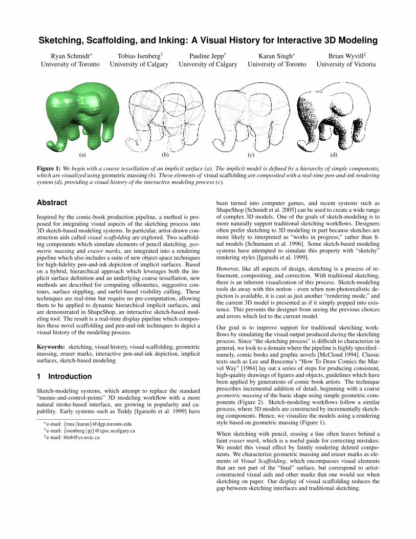
Figure 1: We begin with a coarse tessellation of an implicit surface (a). The implicit model is defined by a hierarchy of simple components,which are visualized using geometric massing (b). These elements of visual scaffolding are composited with a real-time pen-and-ink renderingsystem (d), providing a visual history of the interactive modeling process (c).
Abstract
Inspired by the comic-book production pipeline, a method is pro-posed for integrating visual aspects of the sketching process into3D sketch-based modeling systems. In particular, artist-drawn con-struction aids called visual scaffolding are explored. Two scaffold-ing components which simulate elements of pencil sketching, geo-metric massing and eraser marks, are integrated into a renderingpipeline which also includes a suite of new object-space techniquesfor high-fidelity pen-and-ink depiction of implicit surfaces. Basedon a hybrid, hierarchical approach which leverages both the im-plicit surface definition and an underlying coarse tessellation, newmethods are described for computing silhouettes, suggestive con-tours, surface stippling, and surfel-based visibility culling. Thesetechniques are real-time but require no pre-computation, allowingthem to be applied to dynamic hierarchical implicit surfaces, andare demonstrated in ShapeShop, an interactive sketch-based mod-eling tool. The result is a real-time display pipeline which compos-ites these novel scaffolding and pen-and-ink techniques to depict avisual history of the modeling process.
Keywords: sketching, visual history, visual scaffolding, geometricmassing, eraser marks, interactive pen-and-ink depiction, implicitsurfaces, sketch-based modeling
1 Introduction
Sketch-modeling systems, which attempt to replace the standard“menus-and-control-points” 3D modeling workflow with a morenatural stroke-based interface, are growing in popularity and ca-pability. Early systems such as Teddy [Igarashi et al. 1999] have
∗e-mail: {rms |karan}@dgp.toronto.edu†e-mail: {isenberg |pj}@cpsc.ucalgary.ca‡e-mail: [email protected]
been turned into computer games, and recent systems such asShapeShop [Schmidt et al. 2005] can be used to create a wide rangeof complex 3D models. One of the goals of sketch-modeling is tomore naturally support traditional sketching workflows. Designersoften prefer sketching to 3D modeling in part because sketches aremore likely to interpreted as “works in progress,” rather than fi-nal models [Schumann et al. 1996]. Some sketch-based modelingsystems have attempted to simulate this property with “sketchy”rendering styles [Igarashi et al. 1999].
However, like all aspects of design, sketching is a process of re-finement, compositing, and correction. With traditional sketching,there is an inherent visualization of this process. Sketch-modelingtools do away with this notion - even when non-photorealistic de-piction is available, it is cast as just another “rendering mode,” andthe current 3D model is presented as if it simply popped into exis-tence. This prevents the designer from seeing the previous choicesand errors which led to the current model.
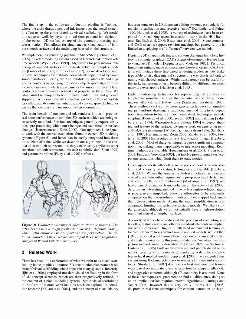
Our goal is to improve support for traditional sketching work-flows by simulating the visual output produced during the sketchingprocess. Since “the sketching process” is difficult to characterize ingeneral, we look to a domain where the pipeline is highly specified -namely, comic books and graphic novels [McCloud 1994]. Classictexts such as Lee and Buscema’s “How To Draw Comics the Mar-vel Way” [1984] lay out a series of steps for producing consistent,high-quality drawings of figures and objects, guidelines which havebeen applied by generations of comic book artists. The techniqueprescribes incremental addition of detail, beginning with a coarsegeometric massing of the basic shape using simple geometric com-ponents (Figure 2). Sketch-modeling workflows follow a similarprocess, where 3D models are constructed by incrementally sketch-ing components. Hence, we visualize the models using a renderingstyle based on geometric massing (Figure 1).
When sketching with pencil, erasing a line often leaves behind afaint eraser mark, which is a useful guide for correcting mistakes.We model this visual effect by faintly rendering deleted compo-nents. We characterize geometric massing and eraser marks as ele-ments of Visual Scaffolding, which encompasses visual elementsthat are not part of the “final” surface, but correspond to artist-constructed visual aids and other marks that one would see whensketching on paper. Our display of visual scaffolding reduces thegap between sketching interfaces and traditional sketching.
The final step in the comic-art production pipeline is “inking,”where the artist draws a pen-and-ink image over the pencil sketch,in effect using the entire sketch as visual scaffolding. We modelthis stage as well, by layering a real-time pen-and-ink depictionof the current 3D surface on top of the geometric massing anderaser marks. This allows for simultaneous visualization of boththe smooth surface and the underlying internal model structure.
We implement our rendering pipeline in ShapeShop [Schmidt et al.2005], a sketch-modeling system based on hierarchical implicit vol-ume models [Wyvill et al. 1999]. Algorithms for pen-and-ink ren-dering of implicit surfaces are non-interactive on complex mod-els [Foster et al. 2005; Stroila et al. 2007], so we develop a suiteof novel techniques for real-time pen-and-ink depiction of dynamicsmooth surfaces. Briefly, we find low-fidelity silhouette and sug-gestive contours by applying brute-force object-space algorithms toa coarse base mesh which approximates the smooth surface. Thesecontours are incrementally refined and projected to the surface. Weadapt surfel techniques to both remove hidden lines and generatestippling. A hierarchical data structure provides efficient visibil-ity culling and dynamic instantiation, and view-adaptive techniquesensure that contours remain smooth when zooming in.
The main benefit of our pen-and-ink renderer is that it providesreal-time performance on complex 3D surfaces which are being in-teractively modified. Previous techniques generally require costlymesh pre-processing which must be repeated each time the surfacechanges [Hertzmann and Zorin 2000]. Our approach is designedto work with the coarse tessellations found in current 3D modelingsystems (Figure 6), and hence can be easily integrated into thesetools. Note also that while we describe our algorithms in the con-text of an implicit representation, they can be easily applied to otherfunctional smooth representations such as subdivision [Stam 1998]and parametric spline [Foley et al. 1996] surfaces.
Figure 2: Character sketching is often an iterative process. Theartist begins with a rough geometric “massing” (leftmost image),which helps ensure correct proportions and perspective. The de-tailed character is then sketched over top of this visual scaffolding.(Images © Wizard Entertainment, Inc).
2 Related Work
There has been little exploration of what we refer to as visual scaf-folding in the graphics literature. 3D construction planes are a basicform of visual scaffolding which appear in many systems. Recently,[Ijiri et al. 2006] employed transient visual scaffolding in the formof 3D concept sketches, which are then progressively refined, inthe context of a plant-modeling system. Static visual scaffoldingin the form of instructive visual aids has been explored in educa-tion research [Khusro et al. 2004], and the concept of visual history
has seen some use in 2D document editing systems, particularly forrevision visualization and selective “undo” [Kurlander and Feiner1990; Hardock et al. 1993]. A variety of techniques have been ex-plored for visualizing recent interaction history in the HCI litera-ture [Baudisch et al. 2006; Bezerianos et al. 2006]. Some commer-cial CAD systems support revision tracking, but generally this islimited to displaying the “difference” between two models.
Depicting 3D shapes with line and contour drawings has a long his-tory in computer graphics. CAD systems often employ feature linesto visualize 3D models [Requicha and Voelcker 1982]. Technicallimitations initially made this necessary, however current CAD sys-tems still include these line-based rendering modes, as they makeit possible to visualize internal structure in a way that is difficult tomimic with shaded surfaces. While transparency can be useful forthis task, transparent objects become difficult to differentiate whenmany are overlapping [Harrison et al. 1995].
Early line-drawing techniques for representing 3D surfaces at-tempted to simulate the lines that an artist would draw, focus-ing on silhouette and feature lines [Saito and Takahashi 1990].These methods evolved into more general techniques for simulat-ing pen-and-ink drawing, a traditional method of artistic depic-tion. In addition to feature lines, pen-and-ink techniques includestippling [Deussen et al. 2000; Secord 2002] and hatching [Salis-bury et al. 1994; Winkenbach and Salesin 1994] to depict shad-ing and texture of the surface. Extensive work on generating pen-and-ink-style renderings [Winkenbach and Salesin 1996; Salisburyet al. 1997; Hertzmann and Zorin 2000; Zander et al. 2004; Fos-ter et al. 2005] has resulted in very high-quality images [Isenberget al. 2006]. Most of these techniques require significant computa-tion time, making them inapplicable to interactive modeling. Real-time methods are available [Freudenberg et al. 2001; Praun et al.2001; Fung and Veryovka 2003], but involve pre-computed surface-parameterizations which limit them to static models.
Object-space mesh silhouettes are a key component of our sys-tem, and a variety of existing techniques are available [Isenberget al. 2003]. We use the simplest brute-force methods, as more ad-vanced algorithms either require costly pre-processing [Hertzmannand Zorin 2000], or are randomized [Markosian et al. 1997] andhence cannot guarantee frame-coherence. Kirsanov et al. [2003]describe an interesting method in which a high-resolution meshis progressively simplified, allowing silhouettes to be efficientlycomputed on the low-resolution mesh and then mapped back ontothe high-resolution mesh. Again, the mesh simplification is pre-computed, limiting this technique to static models. We take a sim-ilar approach, although we do not initially have a high-resolutionmesh, but instead an implicit surface.
A variety of works have addressed the problem of computing sil-houettes, feature curves, and other pen-and-ink elements on implicitsurfaces. Bremer and Hughes [1998] used incremental techniquesto trace silhouette loops around simple implicit models, while Elber[1998] projected points from a base mesh onto the implicit surfaceand created strokes using this point distribution. We adapt this pro-jection method, initially described by [Meier 1996], in Section 4.Foster et al. [2005] built on these tracing and particle-based tech-niques, creating a full pen-and-ink rendering system for complexhierarchical implicit models. Jepp et al. [2006] have extended thissystem using flocking techniques to render additional surface con-tours. Stroila et al. [2007] describe a robust mathematical frame-work based on implicit-surface intersection to compute silhouette
and suggestive contours, although C3 continuity is assumed. Noneof these techniques are guaranteed to find all silhouettes, doing soon an implicit surface requires interval algorithms [Plantinga andVegter 2006], however this is very costly. Burns et al. [2005]do provide real-time techniques for contour extraction on high-
resolution volume data, but the 3D sampling required to convert ourimplicit models into this representation is very time-consuming.
While some of these techniques are capable of interactive perfor-mance, few scale to complex models, and none would maintainreal-time performance on complex implicit models which are be-ing interactively modified. Particle-based methods can attempt tointeractively “track” the surface, but significant changes (particu-larly topology change) are still very costly.
3 Visual Scaffolding
Most work in computer-generated artistic depiction focuses on sim-ulating the artist’s finished work - the watercolor painting, cartoonrendering, or pen-and-ink image. However, artists rarely producefinal pieces “from scratch.” Generally a constructive process is fol-lowed, often beginning with “concept sketches” of varying levels ofdetail. Even at the sketching stage, there are often conventions forbuilding up the drawing. An interesting case study is the domain ofcomic books and graphic novels [McCloud 1994].
The production of comic book art follows a well-defined construc-tion pipeline prescribed by classic texts such as [Lee and Buscema1984]. Human figures begin as a sketched assembly of geometricshapes, similar to the “massing” models common in architecturaldesign. The artist then sketches over top of this first pass with incre-mentally more detailed sets of contours, using the geometric shapesas a guide to maintain proportions and perspective (Figure 2). Theinitial geometric sketch is not part of the final drawing, parts of itwhich remain visible are usually erased. Hence, it can be consid-ered an artist-generated visual construction aid, a particular elementof what we call visual scaffolding.
After the highly-detailed sketch is complete, it is turned into a pen-and-ink image and possibly colored. The inking step is often per-formed by a separate artist, the “inker,” who does not simply traceover the initial sketch, but rather uses it as a guide to produce a com-pelling pen-and-ink depiction. So, to the inker, the entire sketch isvisual scaffolding.
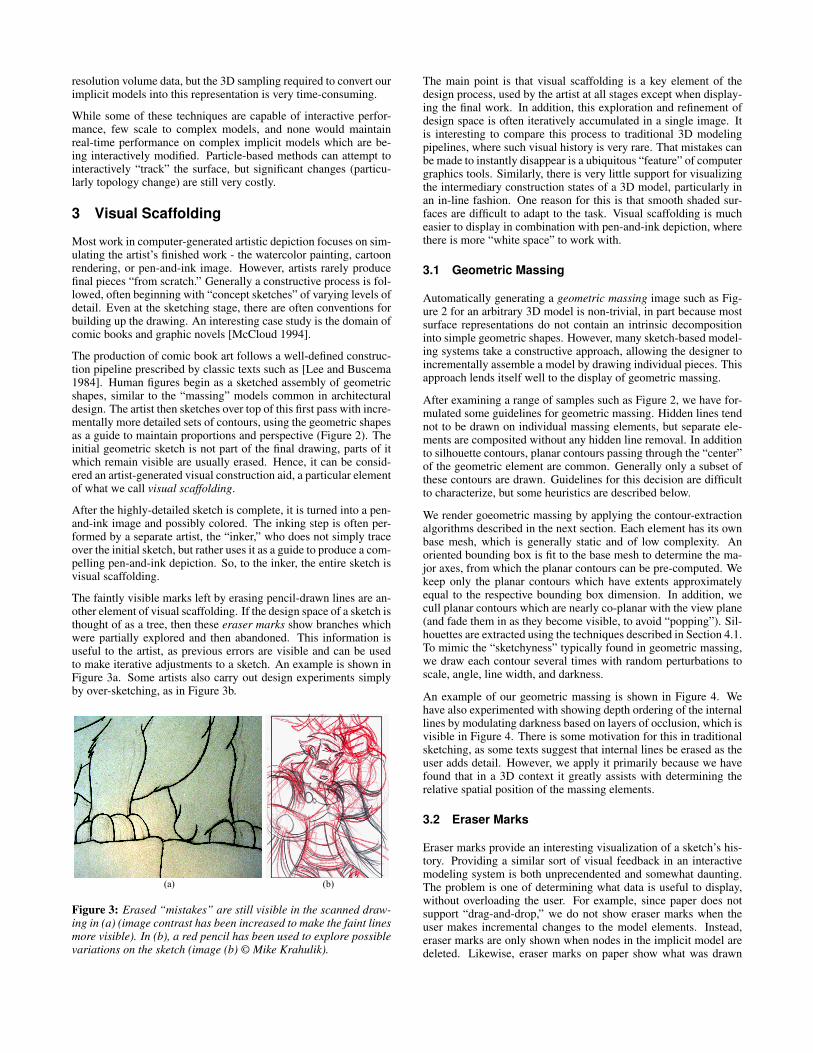
The faintly visible marks left by erasing pencil-drawn lines are an-other element of visual scaffolding. If the design space of a sketch isthought of as a tree, then these eraser marks show branches whichwere partially explored and then abandoned. This information isuseful to the artist, as previous errors are visible and can be usedto make iterative adjustments to a sketch. An example is shown inFigure 3a. Some artists also carry out design experiments simplyby over-sketching, as in Figure 3b.
Figure 3: Erased “mistakes” are still visible in the scanned draw-ing in (a) (image contrast has been increased to make the faint linesmore visible). In (b), a red pencil has been used to explore possiblevariations on the sketch (image (b) © Mike Krahulik).
The main point is that visual scaffolding is a key element of thedesign process, used by the artist at all stages except when display-ing the final work. In addition, this exploration and refinement ofdesign space is often iteratively accumulated in a single image. Itis interesting to compare this process to traditional 3D modelingpipelines, where such visual history is very rare. That mistakes canbe made to instantly disappear is a ubiquitous “feature” of computergraphics tools. Similarly, there is very little support for visualizingthe intermediary construction states of a 3D model, particularly inan in-line fashion. One reason for this is that smooth shaded sur-faces are difficult to adapt to the task. Visual scaffolding is mucheasier to display in combination with pen-and-ink depiction, wherethere is more “white space” to work with.
3.1 Geometric Massing
Automatically generating a geometric massing image such as Fig-ure 2 for an arbitrary 3D model is non-trivial, in part because mostsurface representations do not contain an intrinsic decompositioninto simple geometric shapes. However, many sketch-based model-ing systems take a constructive approach, allowing the designer toincrementally assemble a model by drawing individual pieces. Thisapproach lends itself well to the display of geometric massing.
After examining a range of samples such as Figure 2, we have for-mulated some guidelines for geometric massing. Hidden lines tendnot to be drawn on individual massing elements, but separate ele-ments are composited without any hidden line removal. In additionto silhouette contours, planar contours passing through the “center”of the geometric element are common. Generally only a subset ofthese contours are drawn. Guidelines for this decision are difficultto characterize, but some heuristics are described below.
We render goeometric massing by applying the contour-extractionalgorithms described in the next section. Each element has its ownbase mesh, which is generally static and of low complexity. Anoriented bounding box is fit to the base mesh to determine the ma-jor axes, from which the planar contours can be pre-computed. Wekeep only the planar contours which have extents approximatelyequal to the respective bounding box dimension. In addition, wecull planar contours which are nearly co-planar with the view plane(and fade them in as they become visible, to avoid “popping”). Sil-houettes are extracted using the techniques described in Section 4.1.To mimic the “sketchyness” typically found in geometric massing,we draw each contour several times with random perturbations toscale, angle, line width, and darkness.
An example of our geometric massing is shown in Figure 4. Wehave also experimented with showing depth ordering of the internallines by modulating darkness based on layers of occlusion, which isvisible in Figure 4. There is some motivation for this in traditionalsketching, as some texts suggest that internal lines be erased as theuser adds detail. However, we apply it primarily because we havefound that in a 3D context it greatly assists with determining therelative spatial position of the massing elements.
3.2 Eraser Marks
Eraser marks provide an interesting visualization of a sketch’s his-tory. Providing a similar sort of visual feedback in an interactivemodeling system is both unprecendented and somewhat daunting.The problem is one of determining what data is useful to display,without overloading the user. For example, since paper does notsupport “drag-and-drop,” we do not show eraser marks when theuser makes incremental changes to the model elements. Instead,eraser marks are only shown when nodes in the implicit model aredeleted. Likewise, eraser marks on paper show what was drawn
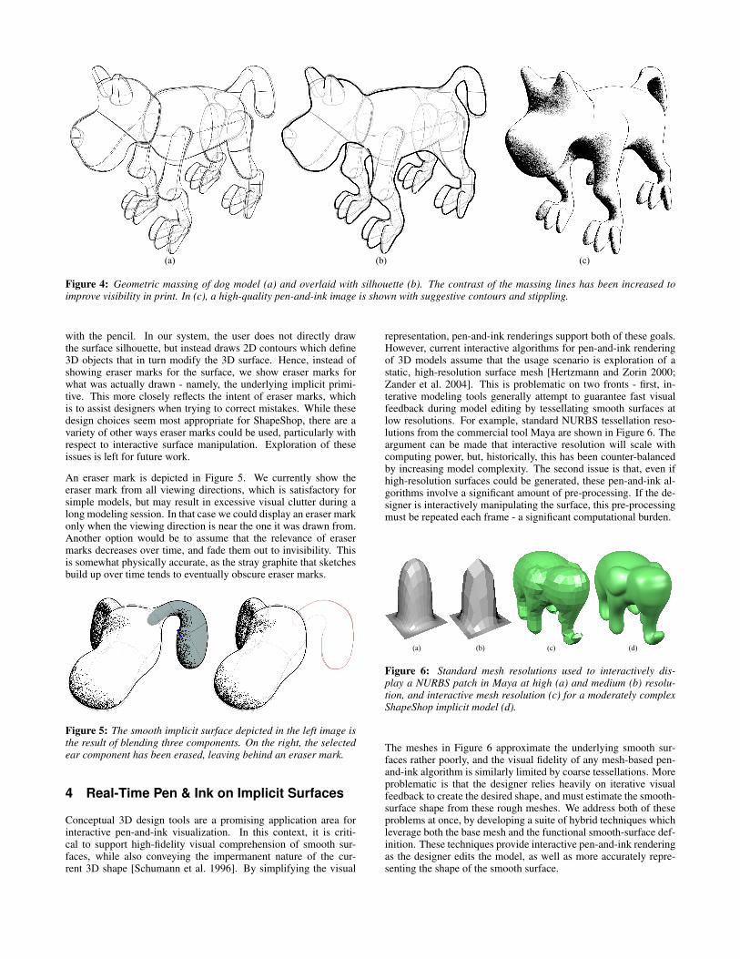
Figure 4: Geometric massing of dog model (a) and overlaid with silhouette (b). The contrast of the massing lines has been increased toimprove visibility in print. In (c), a high-quality pen-and-ink image is shown with suggestive contours and stippling.
with the pencil. In our system, the user does not directly drawthe surface silhouette, but instead draws 2D contours which define3D objects that in turn modify the 3D surface. Hence, instead ofshowing eraser marks for the surface, we show eraser marks forwhat was actually drawn - namely, the underlying implicit primi-tive. This more closely reflects the intent of eraser marks, whichis to assist designers when trying to correct mistakes. While thesedesign choices seem most appropriate for ShapeShop, there are avariety of other ways eraser marks could be used, particularly withrespect to interactive surface manipulation. Exploration of theseissues is left for future work.
An eraser mark is depicted in Figure 5. We currently show theeraser mark from all viewing directions, which is satisfactory forsimple models, but may result in excessive visual clutter during along modeling session. In that case we could display an eraser markonly when the viewing direction is near the one it was drawn from.Another option would be to assume that the relevance of erasermarks decreases over time, and fade them out to invisibility. Thisis somewhat physically accurate, as the stray graphite that sketchesbuild up over time tends to eventually obscure eraser marks.
Figure 5: The smooth implicit surface depicted in the left image isthe result of blending three components. On the right, the selectedear component has been erased, leaving behind an eraser mark.
4 Real-Time Pen & Ink on Implicit Surfaces
Conceptual 3D design tools are a promising application area forinteractive pen-and-ink visualization. In this context, it is criti-cal to support high-fidelity visual comprehension of smooth sur-faces, while also conveying the impermanent nature of the cur-rent 3D shape [Schumann et al. 1996]. By simplifying the visual
representation, pen-and-ink renderings support both of these goals.However, current interactive algorithms for pen-and-ink renderingof 3D models assume that the usage scenario is exploration of astatic, high-resolution surface mesh [Hertzmann and Zorin 2000;Zander et al. 2004]. This is problematic on two fronts - first, in-terative modeling tools generally attempt to guarantee fast visualfeedback during model editing by tessellating smooth surfaces atlow resolutions. For example, standard NURBS tessellation reso-lutions from the commercial tool Maya are shown in Figure 6. Theargument can be made that interactive resolution will scale withcomputing power, but, historically, this has been counter-balancedby increasing model complexity. The second issue is that, even ifhigh-resolution surfaces could be generated, these pen-and-ink al-gorithms involve a significant amount of pre-processing. If the de-signer is interactively manipulating the surface, this pre-processingmust be repeated each frame - a significant computational burden.
Figure 6: Standard mesh resolutions used to interactively dis-play a NURBS patch in Maya at high (a) and medium (b) resolu-tion, and interactive mesh resolution (c) for a moderately complexShapeShop implicit model (d).
The meshes in Figure 6 approximate the underlying smooth sur-faces rather poorly, and the visual fidelity of any mesh-based pen-and-ink algorithm is similarly limited by coarse tessellations. Moreproblematic is that the designer relies heavily on iterative visualfeedback to create the desired shape, and must estimate the smooth-surface shape from these rough meshes. We address both of theseproblems at once, by developing a suite of hybrid techniques whichleverage both the base mesh and the functional smooth-surface def-inition. These techniques provide interactive pen-and-ink renderingas the designer edits the model, as well as more accurately repre-senting the shape of the smooth surface.
4.1 Silhouettes
Given an arbitrary smooth surface S ∈ R3, any point p ∈ S is con-
sidered “on” the silhouette if it satisfies the equality
n ·v = 0 (1)
where n is the surface normal at p, and v = c−p is the view vec-tor to the camera position c. Note that Equation 1 fails at creases,where n is not defined, but in that case one can consider a a limitingprocess which approaches the crease on either side.
Finding solutions to Equation 1 on a complex smooth surface is notfeasible in an interactive system. And, as we have noted, simplyusing the interactive mesh, which we will call the base mesh, isunsatisfactory. Hence, we use both - our general approach is to findcoarse silhouette contours on the base mesh, and then project themonto the smooth surface. While this is only an approximation, wehave found it to be very effective.
The first step is to find object-space silhouette contours on the basemesh. We use the basic brute-force approach, evaluating n · v ateach vertex of the mesh and extracting all edges whose verticeshave opposite signs. It is critical to our method that n be accu-rately computed from from the smooth surface definition - normalsapproximated from the coarse base mesh are much too noisy.
These initial edges are a very coarse approximation to the silhou-ette contour, so a simple refinement is to find the zero-crossingalong each edge, and connect the “mid-edge” points with lines ly-ing across the triangle faces [Hertzmann and Zorin 2000]. Thesesub-polygon silhouettes provide an accurate approximation of thebase mesh silhouette, an example is shown in Figure 7a.
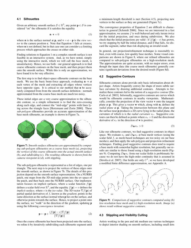
Figure 7: Smooth-surface silhouettes are approximated by comput-ing sub-polygon silhouettes on a coarse base mesh (a), projectingthe vertices of this coarse silhouette onto the actual smooth surface(b), and subdividing (c). The resulting silhouette is shown from thecamera viewpoint in (d), with stippling.
The sub-polygon silhouette is represented as a list of edges, one pertriangle. The next step is to project the vertices of these edges ontothe smooth surface, as shown in Figure 7b. The details of this pro-jection depend on the smooth surface representation. On a NURBSpatch, one maps from the 3D mid-edge points into the uv-space ofthe patch, and then back onto the NURBS surface. Our implemen-tation focuses on implicit surfaces, where a scalar function f(p)
defines a scalar field over R3, and the equality f(p) = v defines the
implicit surface, where v is the iso-value. The 3D vector∇f(p) ofpartial spatial derivatives of f , known as the gradient, points in thesame direction as the surface normal when p lies on the surface, andotherwise points towards the surface. Hence, to project a point ontothe surface, we “walk” in the direction of the gradient, updating pusing the following convergence iteration:
p← p+(f(p)−v)∇f(p)
‖∇f(p)‖(2)
Once the coarse silhouette has been been projected onto the surface,we refine it by iteratively subdividing each silhouette segment until
a minimum-length threshold is met (Section 4.5), projecting newvertices to the surface as they are generated (Figure 7c).
The convergence properties of Equation 2 are difficult to charac-terize in general [Schmidt 2006]. Since we are interested in a fastapproximation, we assume f is well-behaved and only iterate twicefor the initial projection, and once during subdivision. We alsocheck that the initial projections are valid - if |f(p)−v| has grown,we try stepping by half the initial distance, and if that fails, we dis-card the segment, rather than risk displaying an invalid result.
In general, our projection/refinement technique is reasonably ro-bust, even with coarse, low-quality base meshes. Some visual com-parisons are shown in Figure 8, where our refined silhouettes arecompared to sub-polygon silhouettes on a high-resolution mesh.The approximations are quite accurate, with no major errors, eventhough the input data (the coarse mesh silhouette) generally con-tains significant deviations from the desired result (Figure 8d).
4.2 Suggestive Contours
Silhouette contours alone provide only basic information about ob-ject shape. Artists frequently convey the shape of more subtle sur-face curvature by drawing additional contours. Attempts to for-malize these contours led to the notion of a suggestive contour [De-Carlo et al. 2003]. Informally, suggestive contours are curves whichwould be silhouette contours in nearby viewpoints. Mathemati-cally, consider the projection of the view vector v onto the tangentplane at p. This gives a vector w which, along with n, defines theradial plane at p. Taking the intersection between this plane andthe surface near p produces a 2D curve lying in the radial plane, thecurvature of which is is the radial curvature κr . Suggestive con-tours can then be defined as points where κr = 0 and the directionalderivative of κr in the direction of w is positive:
Dwκr > 0 (3)
Like our silhouette contours, we find suggestive contours in objectspace. We evaluate κr and Dwκr at base mesh vertices (using thescalar field f , as mesh-based techniques are too noisy on our basemeshes), and then apply the sub-polygon and projection-refinementtechniques. Finding good suggestive contours does tend to requirea base mesh with somewhat higher resolution, but generally our re-sults are similar to those found using a high-resolution mesh (Fig-ure 9). Computing Dwκr from our scalar fields is problematic be-cause we do not have the high-order continuity that is assumed in
[Stroila et al. 2007]. Our fields are only C1, so we have developeda modified finite difference approximation, see Appendix A.
Figure 9: Comparison of suggestive contours computed using (b)low-resolution base mesh and (c) high-resolution mesh. Image (a)shows result without suggestive contours.
4.3 Stippling and Visibility Culling
Artists working in the pen and ink medium use various techniquesto depict interior shading on smooth surfaces, including small dots
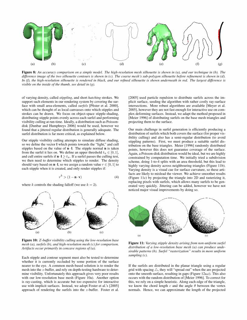
Figure 8: An accuracy comparison on a simple model. The high-resolution mesh silhouette is shown in (a), and our technique in (b). Thedifference image of the two silhouette contours is shown in (c). The coarse mesh’s sub-polygon silhouette before refinement is shown in (d).In (f), the high-resolution silhouette is rendered in black, and our refined silhouette is shown underneath in red. The largest difference isvisible on the inside of the thumb, see detail in (g).
of varying density, called stippling, and short hatching strokes. Wesupport such elements in our rendering system by covering the sur-face with small area-elements, called surfels [Pfister et al. 2000],which can be thought of as local canvasses onto which stipples andstrokes can be drawn. We focus on object-space stipple-shading,distributing stipple points evenly across each surfel and performingvisibility culling at run-time. Ideally, a distribution such as Poisson-disk [Dunbar and Humphreys 2006] would be used, however wefound that a jittered regular distribution is generally adequate. Thesurfel distribution is far more critical, as explained below.
Our stipple visibility culling attempts to simulate diffuse shading,so we define the vector l which points towards the “light,” and cullstipples based on the value of n · l. The stipple normal n is takenfrom the surfel it lies on. We define an upper threshold tu ∈ [0,1],and cull entire surfels if n · l≥ tu. If a surfel passes the culling test,we then need to determine which stipples to render. The densityshould vary based on n · l, so we assign a random value r ∈ [0,1] toeach stipple when it is created, and only render stipples if:
rk > (1−n ·v) (4)
where k controls the shading falloff (we use k = 2).
Figure 10: Z-buffer visibility culling using the low-resolution basemesh (a), surfels (b), and high-resolution mesh (c) for comparison.Artifacts occur primarily in concave regions of (a).
Each stipple and contour segment must also be tested to determinewhether it is currently occluded by some portion of the surfacenearer to the eye. A common mesh-based solution is to render themesh into the z-buffer, and rely on depth-testing hardware to deter-mine visibility. Unfortunately this approach gives very poor resultswith our low-resolution base mesh (Figure 10a). Another optionis ray-casting, which is accurate but too expensive for interactiveuse with implicit surfaces. Instead, we adopt Foster et al.’s [2005]approach of rendering the surfels into the z-buffer. Foster et al.
[2005] used particle repulsion to distribute surfels across the im-plicit surface, seeding the algorithm with rather costly ray-surfaceintersections. More robust algorithms are available [Meyer et al.2005], however they are not fast enough for interactive use on com-plex deforming surfaces. Instead, we adapt the method proposed in[Meier 1996] of distributing surfels on the base mesh triangles andprojecting them to the surface.
Our main challenge in surfel generation is efficiently producing adistribution of surfels which both covers the surface (for proper vis-ibility culling) and also has a semi-regular distribution (to avoidstippling patterns). First, we must produce a suitable surfel dis-tribution on the base triangles. Meier [1996] randomly distributedpoints, however this does not guarantee coverage of the surface.Again, a Poisson-disk distribution would be ideal, but we are highlyconstrained by computation time. We initially tried a subdivisionscheme, doing 1-to-4 splits with an area threshold, but this lead tohighly varying density across neighbouring triangles (Figure 11b).Varying density is a visual cue for surface curvature, so these arti-facts are likely to mislead the viewer. We achieve smoother results(Figure 11c) by projecting the triangle into 2D and rasterizing it,replacing pixels with surfels, which allows many surfels to be gen-erated very quickly. Jittering can be added, however we have notnoticed major visual improvements by doing so.
Figure 11: Varying stipple density arising from non-uniform surfeldistribution of a low-resolution base mesh (a) can produce unde-sirable patterns (b). Surfel “rasterization” results in more uniformsampling (c).
If the surfels are distributed in the planar triangle using a regulargrid with spacing4, they will “spread out” when the are projectedonto the smooth surface, resulting in gaps (Figure 12a,c). This alsooccurs with the random distribution of [Meier 1996]. To correct forthis, we rely on a simple heuristic. Along each edge of the triangle,we know the chord length c and the angle θ between the vertexnormals. Hence, we can approximate the length of the projected
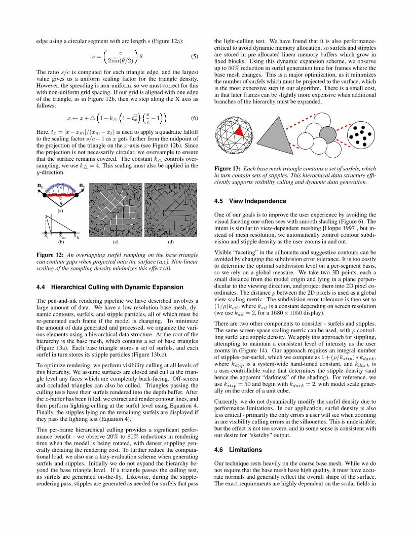
edge using a circular segment with arc length s (Figure 12a):
s =
�c
2sin(θ/2)� θ (5)
The ratio s/c is computed for each triangle edge, and the largestvalue gives us a uniform scaling factor for the triangle density.However, the spreading is non-uniform, so we must correct for thiswith non-uniform grid spacing. If our grid is aligned with one edgeof the triangle, as in Figure 12b, then we step along the X axis asfollows:
x← x+4 �1−k4 �1− t2x� �s
c−1�� (6)
Here, tx = |x−xm|/(xm−xl) is used to apply a quadratic falloffto the scaling factor s/c−1 as x gets further from the midpoint ofthe projection of the triangle on the x-axis (see Figure 12b). Sincethe projection is not necessarily circular, we oversample to ensurethat the surface remains covered. The constant k4 controls over-sampling, we use k4 = 4. This scaling must also be applied in they-direction.
Figure 12: An overlapping surfel sampling on the base trianglecan contain gaps when projected onto the surface (a,c). Non-linearscaling of the sampling density minimizes this effect (d).
4.4 Hierarchical Culling with Dynamic Expansion
The pen-and-ink rendering pipeline we have described involves alarge amount of data. We have a low-resolution base mesh, dy-namic contours, surfels, and stipple particles, all of which must bere-generated each frame if the model is changing. To minimizethe amount of data generated and processed, we organize the vari-ous elements using a hierarchical data structure. At the root of thehierarchy is the base mesh, which contains a set of base triangles(Figure 13a). Each base triangle stores a set of surfels, and eachsurfel in turn stores its stipple particles (Figure 13b,c).
To optimize rendering, we perform visibility culling at all levels ofthis hierarchy. We assume surfaces are closed and cull at the trian-gle level any faces which are completely back-facing. Off-screenand occluded triangles can also be culled. Triangles passing theculling tests have their surfels rendered into the depth buffer. Afterthe z-buffer has been filled, we extract and render contour lines, andthen perform lighting-culling at the surfel level using Equation 4.Finally, the stipples lying on the remaining surfels are displayed ifthey pass the lighting test (Equation 4).
This per-frame hierarchical culling provides a significant perfor-mance benefit - we observe 20% to 80% reductions in renderingtime when the model is being rotated, with denser stippling gen-erally dictating the rendering cost. To further reduce the computa-tional load, we also use a lazy-evaluation scheme when generatingsurfels and stipples. Initially we do not expand the hierarchy be-yond the base triangle level. If a triangle passes the culling test,its surfels are generated on-the-fly. Likewise, during the stipple-rendering pass, stipples are generated as needed for surfels that pass
the light-culling test. We have found that it is also performance-critical to avoid dynamic memory allocation, so surfels and stipplesare stored in pre-allocated linear memory buffers which grow infixed blocks. Using this dynamic expansion scheme, we observeup to 50% reduction in surfel generation time for frames where thebase mesh changes. This is a major optimization, as it minimizesthe number of surfels which must be projected to the surface, whichis the most expensive step in our algorithm. There is a small cost,in that later frames can be slightly more expensive when additionalbranches of the hierarchy must be expanded.
Figure 13: Each base mesh triangle contains a set of surfels, whichin turn contain sets of stipples. This hierachical data structure effi-ciently supports visibility culling and dynamic data generation.
4.5 View Independence
One of our goals is to improve the user experience by avoiding thevisual faceting one often sees with smooth shading (Figure 6). Theintent is similar to view-dependent meshing [Hoppe 1997], but in-stead of mesh resolution, we automatically control contour subdi-vision and stipple density as the user zooms in and out.
Visible “faceting” in the silhouette and suggestive contours can beavoided by changing the subdivision error tolerance. It is too costlyto determine the optimal subdivision level on a per-segment basis,so we rely on a global measure. We take two 3D points, each asmall distance from the model origin and lying in a plane perpen-dicular to the viewing direction, and project them into 2D pixel co-ordinates. The distance ρ between the 2D pixels is used as a globalview-scaling metric. The subdivision error tolerance is then set to(1/ρ)ksil, where ksil is a constant depending on screen resolution(we use ksil = 2, for a 1680×1050 display).
There are two other components to consider - surfels and stipples.The same screen-space scaling metric can be used, with ρ control-ling surfel and stipple density. We apply this approach for stippling,attempting to maintain a consistent level of intensity as the userzooms in (Figure 14). Our approach requires an integral numberof stipples-per-surfel, which we compute as 1+(ρ/kstip)∗kdark,where kstip is a system-wide hand-tuned constant, and kdark isa user-controllable value that determines the stipple density (andhence the apparent “darkness” of the shading). For reference, weuse kstip = 50 and begin with kdark = 2, with model scale gener-ally on the order of a unit cube.
Currently, we do not dynamically modify the surfel density due toperformance limitations. In our application, surfel density is alsoless critical - primarily the only errors a user will see when zoomingin are visibility culling errors in the silhouettes. This is undesirable,but the effect is not too severe, and in some sense is consistent withour desire for “sketchy” output.
4.6 Limitations
Our technique rests heavily on the coarse base mesh. While we donot require that the base mesh have high quality, it must have accu-rate normals and generally reflect the overall shape of the surface.The exact requirements are highly dependent on the scalar fields in
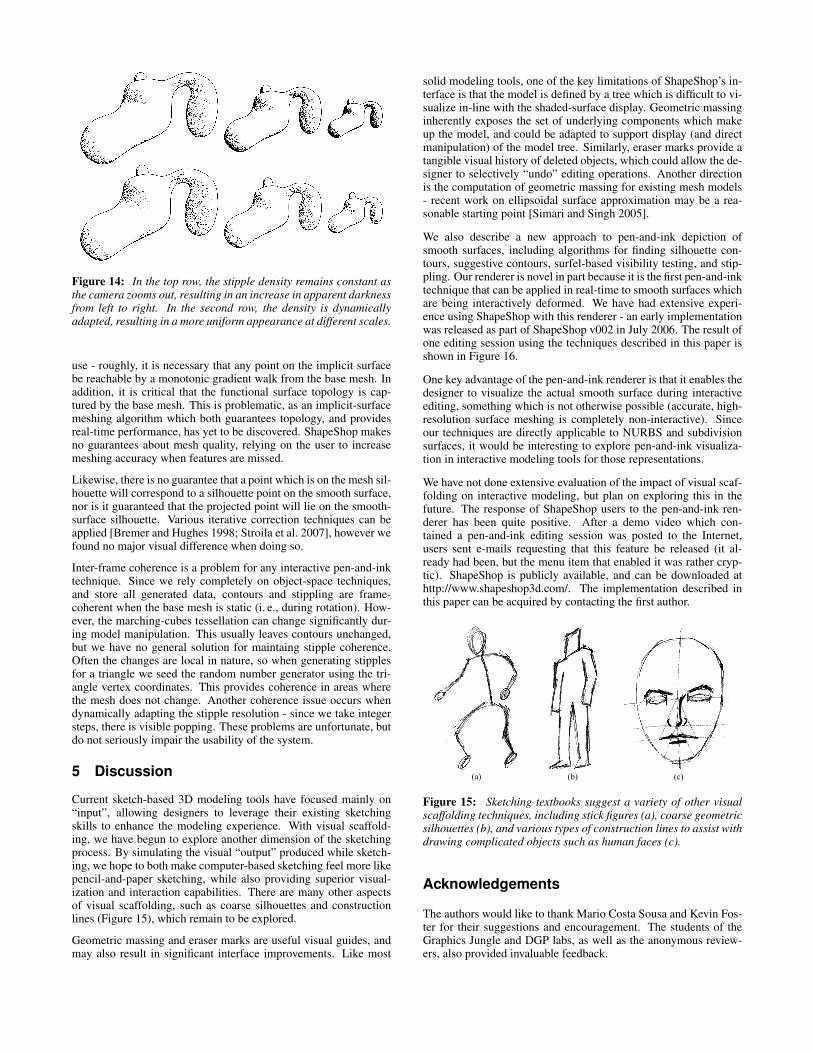
Figure 14: In the top row, the stipple density remains constant asthe camera zooms out, resulting in an increase in apparent darknessfrom left to right. In the second row, the density is dynamicallyadapted, resulting in a more uniform appearance at different scales.
use - roughly, it is necessary that any point on the implicit surfacebe reachable by a monotonic gradient walk from the base mesh. Inaddition, it is critical that the functional surface topology is cap-tured by the base mesh. This is problematic, as an implicit-surfacemeshing algorithm which both guarantees topology, and providesreal-time performance, has yet to be discovered. ShapeShop makesno guarantees about mesh quality, relying on the user to increasemeshing accuracy when features are missed.
Likewise, there is no guarantee that a point which is on the mesh sil-houette will correspond to a silhouette point on the smooth surface,nor is it guaranteed that the projected point will lie on the smooth-surface silhouette. Various iterative correction techniques can beapplied [Bremer and Hughes 1998; Stroila et al. 2007], however wefound no major visual difference when doing so.
Inter-frame coherence is a problem for any interactive pen-and-inktechnique. Since we rely completely on object-space techniques,and store all generated data, contours and stippling are frame-coherent when the base mesh is static (i. e., during rotation). How-ever, the marching-cubes tessellation can change significantly dur-ing model manipulation. This usually leaves contours unchanged,but we have no general solution for maintaing stipple coherence.Often the changes are local in nature, so when generating stipplesfor a triangle we seed the random number generator using the tri-angle vertex coordinates. This provides coherence in areas wherethe mesh does not change. Another coherence issue occurs whendynamically adapting the stipple resolution - since we take integersteps, there is visible popping. These problems are unfortunate, butdo not seriously impair the usability of the system.
5 Discussion
Current sketch-based 3D modeling tools have focused mainly on“input”, allowing designers to leverage their existing sketchingskills to enhance the modeling experience. With visual scaffold-ing, we have begun to explore another dimension of the sketchingprocess. By simulating the visual “output” produced while sketch-ing, we hope to both make computer-based sketching feel more likepencil-and-paper sketching, while also providing superior visual-ization and interaction capabilities. There are many other aspectsof visual scaffolding, such as coarse silhouettes and constructionlines (Figure 15), which remain to be explored.
Geometric massing and eraser marks are useful visual guides, andmay also result in significant interface improvements. Like most
solid modeling tools, one of the key limitations of ShapeShop’s in-terface is that the model is defined by a tree which is difficult to vi-sualize in-line with the shaded-surface display. Geometric massinginherently exposes the set of underlying components which makeup the model, and could be adapted to support display (and directmanipulation) of the model tree. Similarly, eraser marks provide atangible visual history of deleted objects, which could allow the de-signer to selectively “undo” editing operations. Another directionis the computation of geometric massing for existing mesh models- recent work on ellipsoidal surface approximation may be a rea-sonable starting point [Simari and Singh 2005].
We also describe a new approach to pen-and-ink depiction ofsmooth surfaces, including algorithms for finding silhouette con-tours, suggestive contours, surfel-based visibility testing, and stip-pling. Our renderer is novel in part because it is the first pen-and-inktechnique that can be applied in real-time to smooth surfaces whichare being interactively deformed. We have had extensive experi-ence using ShapeShop with this renderer - an early implementationwas released as part of ShapeShop v002 in July 2006. The result ofone editing session using the techniques described in this paper isshown in Figure 16.
One key advantage of the pen-and-ink renderer is that it enables thedesigner to visualize the actual smooth surface during interactiveediting, something which is not otherwise possible (accurate, high-resolution surface meshing is completely non-interactive). Sinceour techniques are directly applicable to NURBS and subdivisionsurfaces, it would be interesting to explore pen-and-ink visualiza-tion in interactive modeling tools for those representations.
We have not done extensive evaluation of the impact of visual scaf-folding on interactive modeling, but plan on exploring this in thefuture. The response of ShapeShop users to the pen-and-ink ren-derer has been quite positive. After a demo video which con-tained a pen-and-ink editing session was posted to the Internet,users sent e-mails requesting that this feature be released (it al-ready had been, but the menu item that enabled it was rather cryp-tic). ShapeShop is publicly available, and can be downloaded athttp://www.shapeshop3d.com/. The implementation described inthis paper can be acquired by contacting the first author.
Figure 15: Sketching textbooks suggest a variety of other visualscaffolding techniques, including stick figures (a), coarse geometricsilhouettes (b), and various types of construction lines to assist withdrawing complicated objects such as human faces (c).
Acknowledgements
The authors would like to thank Mario Costa Sousa and Kevin Fos-ter for their suggestions and encouragement. The students of theGraphics Jungle and DGP labs, as well as the anonymous review-ers, also provided invaluable feedback.
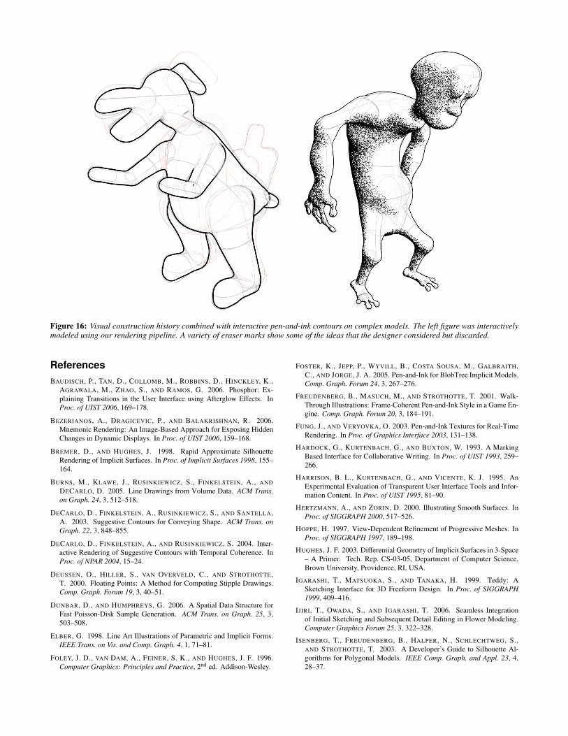
Figure 16: Visual construction history combined with interactive pen-and-ink contours on complex models. The left figure was interactivelymodeled using our rendering pipeline. A variety of eraser marks show some of the ideas that the designer considered but discarded.
References
BAUDISCH, P., TAN, D., COLLOMB, M., ROBBINS, D., HINCKLEY, K.,
AGRAWALA, M., ZHAO, S., AND RAMOS, G. 2006. Phosphor: Ex-
plaining Transitions in the User Interface using Afterglow Effects. In
Proc. of UIST 2006, 169–178.
BEZERIANOS, A., DRAGICEVIC, P., AND BALAKRISHNAN, R. 2006.
Mnemonic Rendering: An Image-Based Approach for Exposing Hidden
Changes in Dynamic Displays. In Proc. of UIST 2006, 159–168.
BREMER, D., AND HUGHES, J. 1998. Rapid Approximate Silhouette
Rendering of Implicit Surfaces. In Proc. of Implicit Surfaces 1998, 155–
164.
BURNS, M., KLAWE, J., RUSINKIEWICZ, S., FINKELSTEIN, A., AND
DECARLO, D. 2005. Line Drawings from Volume Data. ACM Trans.
on Graph. 24, 3, 512–518.
DECARLO, D., FINKELSTEIN, A., RUSINKIEWICZ, S., AND SANTELLA,
A. 2003. Suggestive Contours for Conveying Shape. ACM Trans. on
Graph. 22, 3, 848–855.
DECARLO, D., FINKELSTEIN, A., AND RUSINKIEWICZ, S. 2004. Inter-
active Rendering of Suggestive Contours with Temporal Coherence. In
Proc. of NPAR 2004, 15–24.
DEUSSEN, O., HILLER, S., VAN OVERVELD, C., AND STROTHOTTE,
T. 2000. Floating Points: A Method for Computing Stipple Drawings.
Comp. Graph. Forum 19, 3, 40–51.
DUNBAR, D., AND HUMPHREYS, G. 2006. A Spatial Data Structure for
Fast Poisson-Disk Sample Generation. ACM Trans. on Graph. 25, 3,
503–508.
ELBER, G. 1998. Line Art Illustrations of Parametric and Implicit Forms.
IEEE Trans. on Vis. and Comp. Graph. 4, 1, 71–81.
FOLEY, J. D., VAN DAM, A., FEINER, S. K., AND HUGHES, J. F. 1996.
Computer Graphics: Principles and Practice, 2nd ed. Addison-Wesley.
FOSTER, K., JEPP, P., WYVILL, B., COSTA SOUSA, M., GALBRAITH,
C., AND JORGE, J. A. 2005. Pen-and-Ink for BlobTree Implicit Models.
Comp. Graph. Forum 24, 3, 267–276.
FREUDENBERG, B., MASUCH, M., AND STROTHOTTE, T. 2001. Walk-
Through Illustrations: Frame-Coherent Pen-and-Ink Style in a Game En-
gine. Comp. Graph. Forum 20, 3, 184–191.
FUNG, J., AND VERYOVKA, O. 2003. Pen-and-Ink Textures for Real-Time
Rendering. In Proc. of Graphics Interface 2003, 131–138.
HARDOCK, G., KURTENBACH, G., AND BUXTON, W. 1993. A Marking
Based Interface for Collaborative Writing. In Proc. of UIST 1993, 259–
266.
HARRISON, B. L., KURTENBACH, G., AND VICENTE, K. J. 1995. An
Experimental Evaluation of Transparent User Interface Tools and Infor-
mation Content. In Proc. of UIST 1995, 81–90.
HERTZMANN, A., AND ZORIN, D. 2000. Illustrating Smooth Surfaces. In
Proc. of SIGGRAPH 2000, 517–526.
HOPPE, H. 1997. View-Dependent Refinement of Progressive Meshes. In
Proc. of SIGGRAPH 1997, 189–198.
HUGHES, J. F. 2003. Differential Geometry of Implicit Surfaces in 3-Space
– A Primer. Tech. Rep. CS-03-05, Department of Computer Science,
Brown University, Providence, RI, USA.
IGARASHI, T., MATSUOKA, S., AND TANAKA, H. 1999. Teddy: A
Sketching Interface for 3D Freeform Design. In Proc. of SIGGRAPH
1999, 409–416.
IJIRI, T., OWADA, S., AND IGARASHI, T. 2006. Seamless Integration
of Initial Sketching and Subsequent Detail Editing in Flower Modeling.
Computer Graphics Forum 25, 3, 322–328.
ISENBERG, T., FREUDENBERG, B., HALPER, N., SCHLECHTWEG, S.,
AND STROTHOTTE, T. 2003. A Developer’s Guide to Silhouette Al-
gorithms for Polygonal Models. IEEE Comp. Graph. and Appl. 23, 4,
28–37.
ISENBERG, T., NEUMANN, P., CARPENDALE, S., COSTA SOUSA, M.,
AND JORGE, J. A. 2006. Non-Photorealistic Rendering in Context: An
Observational Study. In Proc. of NPAR 2006, 115–126.
JEPP, P., WYVILL, B., AND SOUSA, M. C. 2006. Smarticles for Sampling
and Rendering Implicit Models. In Proc. of EGUK 2006, 39–46.
KHUSRO, K., MUNYOFU, M., SWAIN, W., AUSMAN, B., LIN, H., AND
DWYER, F. 2004. Effect of Visual Scaffolding and Animation on Stu-
dents’ Performance on Measures of Higher Order Learning. Tech. Rep.
ED485130, Assoc. for Educational Communications and Technology.
KIRSANOV, D., SANDER, P. V., AND GORTLER, S. J. 2003. Simple
Silhouettes for Complex Surfaces. In Proc. of SGP 2003, 102–106.
KURLANDER, D., AND FEINER, S. 1990. A Visual Language for Brows-
ing, Undoing, and Redoing Graphical Interface Commands. In Visual
Languages and Visual Programming, S. Chang, Ed. Plenum Press, 257–
275.
LEE, S., AND BUSCEMA, J. 1984. How to Draw Comics the Marvel Way.
Simon & Schuster, Inc., New York.
MARKOSIAN, L., KOWALSKI, M. A., TRYCHIN, S. J., BOURDEV, L. D.,
GOLDSTEIN, D., AND HUGHES, J. F. 1997. Real-Time Nonphotoreal-
istic Rendering. In Proc. of SIGGRAPH 1997, 415–420.
MCCLOUD, S. 1994. Understanding Comics: The Invisible Art. Harper-
Collins Publishers, Inc., New York.
MEIER, B. J. 1996. Painterly Rendering for Animation. In Proc. of SIG-
GRAPH 1996, 477–484.
MEYER, M. D., GEORGEL, P., AND WHITAKER, R. T. 2005. Robust Par-
ticle Systems for Curvature Dependent Sampling of Implicit Surfaces. In
Proc. of SMI 2005, 124–133.
PFISTER, H., ZWICKER, M., VAN BAAR, J., AND GROSS, M. 2000. Sur-
fels: Surface Elements as Rendering Primitives. In Proc. of SIGGRAPH
2000, 335–342.
PLANTINGA, S., AND VEGTER, G. 2006. Computing Contour Generators
of Evolving Implicit Surfaces. ACM Trans. on Graph. 25, 4, 1243–1280.
PRAUN, E., HOPPE, H., WEBB, M., AND FINKELSTEIN, A. 2001. Real-
Time Hatching. In Proc. of SIGGRAPH 2001, 581–586.
REQUICHA, A. A. G., AND VOELCKER, H. B. 1982. Solid Modeling:
A Historical Summary and Contemporary Assessment. IEEE Comp.
Graph. and Appl. 2, 2, 9–24.
SAITO, T., AND TAKAHASHI, T. 1990. Comprehensible Rendering of 3-D
Shapes. ACM SIGGRAPH Computer Graphics 24, 3, 197–206.
SALISBURY, M. P., ANDERSON, S. E., BARZEL, R., AND SALESIN,
D. H. 1994. Interactive Pen-and-Ink Illustration. In Proc. of SIGGRAPH
1994, 101–108.
SALISBURY, M. P., WONG, M. T., HUGHES, J. F., AND SALESIN, D. H.
1997. Orientable Textures for Image-Based Pen-and-Ink Illustration. In
Proc. of SIGGRAPH 1997, 401–406.
SCHMIDT, R., WYVILL, B., SOUSA, M. C., AND JORGE, J. 2005.
ShapeShop: Sketch-Based Solid Modeling with BlobTrees. In Proc. of
Eurographics Workshop on Sketch-Based Interfaces and Modeling, 53–
62.
SCHMIDT, R. 2006. Interactive Modeling with Implicit Surfaces. Master’s
thesis, Department of Computer Science, University of Calgary, Canada.
SCHUMANN, J., STROTHOTTE, T., RAAB, A., AND LASER, S. 1996.
Assessing the Effect of Non-photorealistic Rendered Images in CAD. In
Proc. of CHI 1996, 35–42.
SECORD, A. 2002. Weighted Voronoi Stippling. In Proc. of NPAR 2002,
37–44.
SIMARI, P., AND SINGH, K. 2005. Extraction and Remeshing of Ellip-
soidal Representations from Mesh Data. In Proc. of Graphics Interface
2005, 161–168.
STAM, J. 1998. Exact Evaluation of Catmull-Clark Subdivision Surfaces at
Arbitrary Parameter Values. In Proc. of SIGGRAPH 1998, 395–404.
STROILA, M., EISEMANN, E., AND HART, J. C. 2007. Clip Art Ren-
dering of Smooth Isosurfaces. IEEE Transactions on Visualization and
Computer Graphics. To appear.
WINKENBACH, G. A., AND SALESIN, D. H. 1994. Computer-Generated
Pen-and-Ink Illustration. In Proc. of SIGGRAPH 1994, 91–100.
WINKENBACH, G. A., AND SALESIN, D. H. 1996. Rendering Parametric
Surfaces in Pen and Ink. In Proc. of SIGGRAPH 1996, 469–476.
WYVILL, B., GUY, A., AND GALIN, E. 1999. Extending the CSG Tree.
Warping, Blending and Boolean Operations in an Implicit Surface Mod-
eling System. Comp. Graph. Forum 18, 2, 149–158.
ZANDER, J., ISENBERG, T., SCHLECHTWEG, S., AND STROTHOTTE, T.
2004. High Quality Hatching. Comp. Graph. Forum 23, 3, 421–430.
A Suggestive Contours on Implicit Surfaces
The appendices of [DeCarlo et al. 2004] provide a thorough overview of the
differential geometry needed to describe suggestive contours. Only the key
equations are repeated here. We follow their notation, where the vectors
e1 and e2 are the perpendicular principal curvature directions at p, while
κ1 and κ2 are the associated principal curvatures. Then K = κ1κ2 is the
Gaussian curvature, and H = (κ1 +κ2)/2 is the mean curvature. We will
also require the directional derivatives of the principal curvatures along the
principal directions, denoted P , Q, S, and T :
P = De1κ1, Q = De2
κ1, S = De1κ2, T = De2
κ2 (7)
The main value that must be computed is the radial curvature κr :
κr = κ1 cos2 φ+κ2 sin2 φ (8)
where φ is the angle between w and e1. At points where κr = 0, the vector
w is re-written as w = ue1 + ve2 (where u = w · e1 and v = w · e2), and
the directional derivative is then:
Dwκr(w)
‖w‖=
C(w,w,w)
‖w‖3+2K cotθ (9)
where θ = cos−1(n ·v). The quantity C(w,w,w) is defined as
C(w,w,w)
‖w‖3=
Pu3 +3Qu2v +3Suv2 +Tv3
‖w‖3(10)
Our implementation considers implicit surfaces, hence we must express
these values in terms of partial derivatives of f . The curvature values can
be computed from the Hessian matrix of second partial derivatives [Hughes
2003]. Unfortunately our implicit surfaces only have analytic derivatives of
first order, because we apply a hierarchical spatial caching scheme which
approximates f with only C1 continuity, and certain composition operators
are also only C1 [Schmidt 2006]. Hence, we approximate the necessary
second partial derivatives by central-differencing the analytic ∇f .
The directional derivatives of principal curvatures require third partial deriv-
atives of f , which we have found to be too inaccurate when approximated
by finite-differencing. Instead, we take advantage of the fact that the “im-
plicit surface” is simply an iso-contour of a volumetric scalar field, and the
notion of “curvature” is defined at all points in this scalar field (assuming
it is continuous in an ε-ball around p). This allows us to directly estimate
Dxκ1 in any direction x by taking finite differences of κ1(p) along the line
p+ tx. For example, the quantity P = De1κ1 is estimated as:
De1κ1(p) =
κ1(p+ δe1)−2κ1(p)+κ1(p− δe1)
δ2(11)
In our tests, this directional finite differencing results in suggestive contours
which are visually more stable and more closely resemble the suggestive
contours computed from mesh-based derivatives. However, we have not
performed any formal analysis of this technique.