skeletal anchorage in orthodontic arch...
TRANSCRIPT
SROMS VOLUME 17.51
SKELETAL ANCHORAGE IN ORTHODONTIC ARCH ALIGNMENT:
CLINICAL PRINCIPLES FOR ORAL & MAXILLOFACIAL SURGEONS
Jessica J. Lee, DDS
INTRODUCTION
The concept of absolute anchorage has been the topic of extensive investigations in orthodontics. Oral and maxillofacial surgeons who receive referrals for surgical placement of orthodontic anchorage devices need to understand the principles underlying this concept and develop a customized surgical protocol for ideal placement of the implants. Detailed and coordinated communications with referring orthodontists are crucial in the proper placement of the orthodontic anchorage, very similar to the com-munications with the restorative dentists who determine the ideal location and axial inclination of the endosseous implants in the esthetic zone. Surgical techniques and axial inclinations of the microimplants are the important factors in establishing functional and stable anchorage. Improper placement will result in failure of implants, encroachment on vital anatomic structures and ultimately a failure to provide a stable anchorage for the planned orthodontic movements of the teeth.
Surgeons often turn to orthodontic literature to understand the concept of skeletal anchorage because numerous clinical case series have been reported. However, due to the variations in clin-ical scenarios, types of the implants used and orthodontic mechanics used, cross comparisons are difficult. Reflecting the interest level across different dental specialties on this topic, there has been a surge in the number of textbooks and articles on absolute anchorage, written primarily by orthodontists, but it is cumbersome for sur-geons to read various literary sources that typi-cally focus on mechanical principles and less on surgical principles. Therefore, the purpose of this chapter is to provide a practical clinical
guide for surgeons, summarizing current litera-ture on the most commonly encountered and representative treatment categories and extrap-olating the pertinent principles that are vital to understanding the basic mechanics and surgi-cal principles of absolute anchorage.
PRINCIPLES OF ABSOLUTE ANCHORAGE
Orthodontic teeth movement often requires maximum skeletal anchorage in order to resist the reciprocal reactive forces (i.e., action and reaction) on the dentition. For example, intru-sion and retraction of anterior dentition can
Skeletal Anchorage for Arch Alignment Jessica J. Lee, DDS
SROMS VOLUME 17.52
cause undesirable displacement of adjacent teeth, hindering the treatment outcome. Opti-mal maxillary and mandibular incisor inclina-tions are important factors in the successful outcome of combined orthodontic and orthog-nathic surgical treatments. Their influence on the final functional and esthetic outcome can-not be overemphasized. Controlling lingual retraction of the incisors and anterior torque are rather difficult tasks using conventional orth-odontic mechanics. Traditionally, labial appli-ances and cervical headgear have been used for various indications in orthodontics, but patient acceptance and compliance can be problem-atic and may result in anchorage loss. Optimal maxillary and mandibular incisor inclinations are important factors in the successful outcome of combined orthodontic and orthognathic sur-gical treatments.
The concept of skeletal anchorage was first introduced by Creekmore and Eklund1 in 1983, when they stated that “with screws, pins, or some other readily removable implant anchored to the jaws, forces might be applied to produce tooth movement in any direction without detrimental reciprocal forces.” Abso-lute skeletal anchorage is a viable alternative to conventional extraoral orthodontic appli-ances such as headgear and intraoral mechan-ics using elastics. Closure of extraction space, molar uprighting, intrusion and distalization of posterior teeth are possible with the use of micro-implants, without the inconvenience of the headgear and the risk of anchorage loss. So-called en-masse retraction of dentition as a unit is also made possible by the use of absolute anchorage. Skeletal anchorage facilitates orth-odontic arch alignment and has been a useful
adjunct in orthognathic surgical cases. The most common clinical uses for skeletal anchorage include Class II lower incisor decompensation and retraction, and closing of extraction spaces.
TADS
Temporary anchorage devices (TADs) refer to implants, screws, pins and onplants that are specifically designed for the purpose of pro-viding skeletal anchorage. In this chapter, the three most commonly used TAD categories will be discussed: microscrews, miniplates, and pal-atal implants.
There are numerous applications for using TADs for orthodontic anchorage. (Table 1) In this chapter, the three most common applica-tions of absolute orthodontic anchorage will be discussed: anterior retraction, protraction and intrusion.
TABLE 1: TREATMENT INDICATIONS FOR TADS:
______________________________________________
1) Anchorage control in maxillary anterior-teeth retraction2) Vertical control of mandibular posterior teeth3) Class II and Class III dental malocclusion4) Molar intrusion in anterior open bite cases5) Bimaxillary dentoalveolar protrusions6) Intrusion of super-erupted molars7) Absence of anchor teeth or compromised peri-odontal health of anchor teeth8) Distilization of posterior teeth9) Class I non-extraction cases with arch length deficiency or crowding
Skeletal Anchorage for Arch Alignment Jessica J. Lee, DDS
SROMS VOLUME 17.53
TABLE 2. ADVANTAGES OF MICROSCREW IMPLANTS
Microscrews
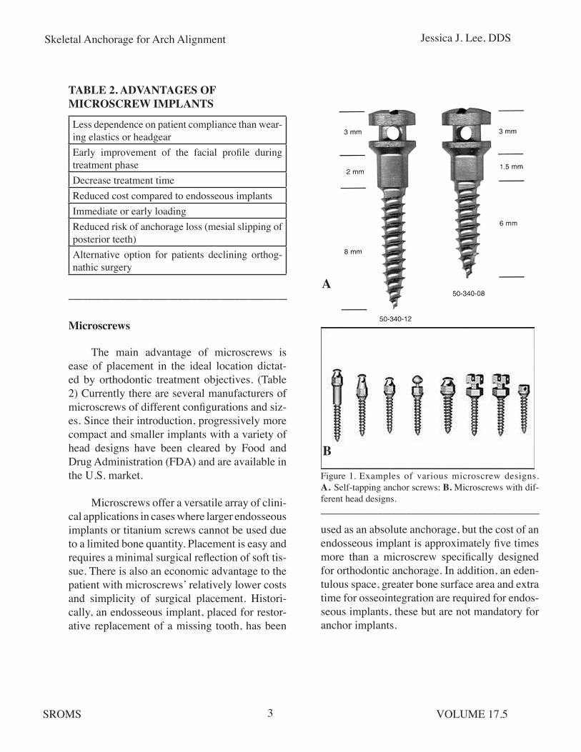
The main advantage of microscrews is ease of placement in the ideal location dictat-ed by orthodontic treatment objectives. (Table 2) Currently there are several manufacturers of microscrews of different configurations and siz-es. Since their introduction, progressively more compact and smaller implants with a variety of head designs have been cleared by Food and Drug Administration (FDA) and are available in the U.S. market.
Microscrews offer a versatile array of clini-cal applications in cases where larger endosseous implants or titanium screws cannot be used due to a limited bone quantity. Placement is easy and requires a minimal surgical reflection of soft tis-sue. There is also an economic advantage to the patient with microscrews’ relatively lower costs and simplicity of surgical placement. Histori-cally, an endosseous implant, placed for restor-ative replacement of a missing tooth, has been
______________________________________________
Figure 1. Examples of various microscrew designs. A. Self-tapping anchor screws; B. Microscrews with dif-ferent head designs. ______________________________________________
used as an absolute anchorage, but the cost of an endosseous implant is approximately five times more than a microscrew specifically designed for orthodontic anchorage. In addition, an eden-tulous space, greater bone surface area and extra time for osseointegration are required for endos-seous implants, these but are not mandatory for anchor implants.
A
B
Less dependence on patient compliance than wear-ing elastics or headgearEarly improvement of the facial profile during treatment phaseDecrease treatment timeReduced cost compared to endosseous implantsImmediate or early loadingReduced risk of anchorage loss (mesial slipping of posterior teeth)Alternative option for patients declining orthog-nathic surgery

Skeletal Anchorage for Arch Alignment Jessica J. Lee, DDS
SROMS VOLUME 17.54
Optimal Size of the Microscrews
Various diameters of microscrews, ranging from 1.2 mm to 2.0 mm, can be used for orthodon-tic anchorage. Smaller diameter microscrews are less likely to encroach on adjacent root structures and, therefore, are favored in narrow interproximal spaces. However, small screws are also more likely to fracture when excessive axial pressure is applied during surgical place-ment.
Fritz et al. reported on 36 microscrews with diameters of 1.4 mm, 1.6 mm and 2.0 mm and lengths of 6 mm, 8 mm and 10 mm placed in 17 patients.2 Anchorage was used for premo-lar distalization, molar uprighting and molar mesialization. The implant sites were equally divided between maxilla and mandible, includ-ing buccal (interradicular), retromolar, and pala-tal (interradicular) placement. The majority of implants were 8 mm in length and 1.6 mm or 2.0 mm in diameter. The mean in-situ time was 158 (+/- 97) days. Eleven fixtures (30%) failed before the conclusion of treatment.
Failure of microscrews results from peri-implant soft tissue inflammation and thin corti-cal bone. Often a small-diameter screw is attrib-uted to implant failure, however, clinical series have demonstrated that microscrew implants of a smaller size (1.2 mm x 6 mm) showed no mobility during the course of treatment with loading forces of 150 g to 200 g two weeks after placement, suggesting that implant failure may be more dependent on the techniques of place-ment than implant size. In general, screw di-ameters less than 1.5 mm should be used with caution in patients younger than 15 years of age (because their cortical bone density is less than that of adults) or in thin cortical bone such as in the maxilla. (Fig. 2)
Figure 2. Panoramic radiograph of an 11-year-old girl who had two microscrews placed for UR4 and UL4 extraction space closure by protraction of posterior segments. The UL4 microscrew loosened shortly after placement and was later replaced with an anchor plate after the second microscrew also became loose. A. Following UL4 micro-screw replacement; B. Following UL4 anchor plate place-ment; C. Before UL4 anchor plate removal. Note that the UR4 microscrew became loose and had to be removed before the space was fully closed. The UL4 anchor plate remained stable until space closure was complete.______________________________________________
Principles of Proper Microscrew Implant Place-ment
In general, placement of microscrews is a simple procedure for oral and maxillofacial surgeons, as long as the surgeon understands the relationship between the desired vector of
A
B
C
Skeletal Anchorage for Arch Alignment Jessica J. Lee, DDS
SROMS VOLUME 17.55
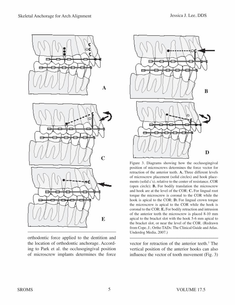
Figure 3. Diagrams showing how the occlusogingival position of microscrews determines the force vector for retraction of the anterior teeth. A. Three different levels of microscrew placement (solid circles) and hook place-ments (solid c’s), relative to the center of resistance, COR (open circle); B. For bodily translation the microscrew and hook are at the level of the COR; C. For lingual root torque the microscrew is coronal to the COR while the hook is apical to the COR; D. For lingual crown torque the microscrew is apical to the COR while the hook is coronal to the COR; E. For bodily retraction and intrusion of the anterior teeth the microscrew is placed 8-10 mm apical to the bracket slot with the hook 5-6 mm apical to the bracket slot, or near the level of the COR. (Redrawn from Cope, J.; Ortho TADs: The Clinical Guide and Atlas. Underdog Media, 2007.)____________________________________________________________________________________________
A
C
B
D
E
orthodontic force applied to the dentition and the location of orthodontic anchorage. Accord-ing to Park et al. the occlusogingival position of microscrew implants determines the force
vector for retraction of the anterior teeth.3 The vertical position of the anterior hooks can also influence the vector of tooth movement (Fig. 3)

Skeletal Anchorage for Arch Alignment Jessica J. Lee, DDS
SROMS VOLUME 17.56
and should be taken into consideration and dis-cussed with the referring orthodontist prior to the surgical appointment.
For bodily retraction of the anterior teeth with intrusion, maxillary microscrews need to be placed 8 mm to 10 mm apical to the bracket slot, with the anterior hooks 5 mm to 6 mm gin-gival to the bracket slot. Park et al. recommend an overcorrection of maxillary anterior retrac-tion to a super Class I relationship due to a ten-dency for relapse.3 En masse retraction of the six anterior teeth results in a reduced treatment time. The amount of maxillary retraction can be tailored to individual cases by evaluating the facial profile and occlusal relationship. In Park, et al’s review of three treatment cases, maxillary anterior teeth were retracted 7 mm to 13 mm, without evidence of root resorption.3
The magnitude of maxillary anterior retraction depends on the age of patients and should be limited in adults. Vertical control of the mandibular posterior teeth has an impact on the final mandibular position and, thus, the facial profile. Class II elastics can cause extrusion of the posterior molars and posterior rotation of the mandible, resulting in a negative effect on the facial profile. The occlusogingival position of the microscrew should be more occlusal in non-extraction cases than in extraction cases because the desired movement is in a horizontal direc-tion.
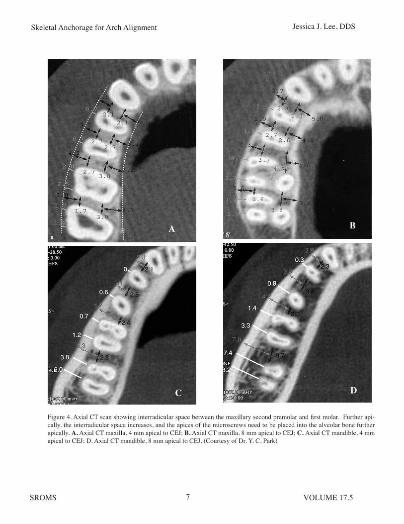
When less than 3 mm of distal movement of the posterior teeth is needed, the microscrews can be placed between the maxillary second premolars and first molars. The mean distance between the roots of the maxillary second pre-molar and first molar is reported to be 3.18 mm at 5 mm to 7 mm apical from the alveolar crest,4
and the apices of the microscrews need to be placed into the alveolar bone further apically than the 5 mm to 7 mm landmark. (Fig. 4) With the microscrew implants placed at 30° to 40° to the long axis of the crown and the implant aimed toward the apex, the implant can be safe-ly placed without encroaching on the roots of the teeth. When there is a root convergence and a lack of interproximal bone between the roots of teeth in the desired location for microscrew placement, then the surgeon must ask the ortho-dontist to diverge the roots prior to the surgical appointment, or proceed with miniplates when anatomic considerations pose a risk of root injury with microscrews.
When more than 3 mm of posterior move-ment of the teeth is anticipated, the palatal alveolar bone between the maxillary first and second molars is the strategic location for microscrew implant placement. In the process of tooth movement, the root surface of the teeth may come in contact with the implant, but the reparative process of the periodontal ligament will take place without the long-term seque-lae.5 An animal study has shown that damage to the periodontal ligament of less than 2 mm can undergo a normal reparative process.5
The vertical position of the implant depends on the type of movement desired. For example, microscrews should be inserted as apically as possible when more intrusion of the tooth is desired (i.e., 6 mm to 10 mm from the cemento-enamel junction instead of 4 mm to 6 mm).
In the mandibular arch, buccal placement of microscrews is a sensible choice, between the mandibular first and second molars, distal to the second molar or in the ramus. Placement depends on the type of tooth movement required,
Skeletal Anchorage for Arch Alignment Jessica J. Lee, DDS
SROMS VOLUME 17.57
Figure 4. Axial CT scan showing interradicular space between the maxillary second premolar and first molar. Further api-cally, the interradicular space increases, and the apices of the microscrews need to be placed into the alveolar bone further apically. A. Axial CT maxilla, 4 mm apical to CEJ; B. Axial CT maxilla, 8 mm apical to CEJ; C. Axial CT mandible, 4 mm apical to CEJ; D. Axial CT mandible, 8 mm apical to CEJ. (Courtesy of Dr. Y. C. Park)
A B
C D

Skeletal Anchorage for Arch Alignment Jessica J. Lee, DDS
SROMS VOLUME 17.58
Figure 5. In the mandibular ramus area, microscrews with a longer soft tissue collar should be used, because the soft tissue thickness interferes with access to the microscrew head, possibly resulting in peri-implant soft tissue irrita-tion.______________________________________________
the location of the inferior alveolar canal, and the availability of adequate bone. In my experi-ence, a longer soft tissue collar should be used with microscrews in the ramus area because the soft tissue thickness interferes with easy access to the microscrew head and can result in peri-implant soft tissue irritation. (Fig. 5) Soft tissue impingement can be problematic around micro-screw implants, but it can be alleviated by using an implant design that includes a head for thread-ing elastics or a coil spring and a smooth surface under the head where the screw contacts the soft tissue. Surgical techniques may vary depending on the specific type of microscrew chosen, but a general surgical sequence applies to most types of microscrew implants. (Table 3)
Radiographic Evaluation
If possible, screws need to be placed in attached mucosa. Schnelle et al. determined radiographically the most coronal interradicu-lar sites for placement of microscrew implants in orthodontic patients, and assessed whether orthodontic alignment increases the number
Figure 6. Surgical sequence for microscrew placement. A. Make a vertical incision 2 mm apical to mucogingi-val junction; B. Reflect the mucoperiosteum; C. Turn the microscrew until the screw head is in contact with soft tissue. (Courtesy of Dr. H. S. Park)______________________________________________
of sites with adequate interradicular bone for screw placement.4 Sixty pre- and post-treatment panoramic radiographs were reviewed. A digital caliper measurement was performed to identify those sites where 3 mm to 4 mm of interradicu-lar bone existed. Then the vertical distance from the cemento-enamel junction to these sites was measured.
A
B
C
Skeletal Anchorage for Arch Alignment Jessica J. Lee, DDS
SROMS VOLUME 17.59
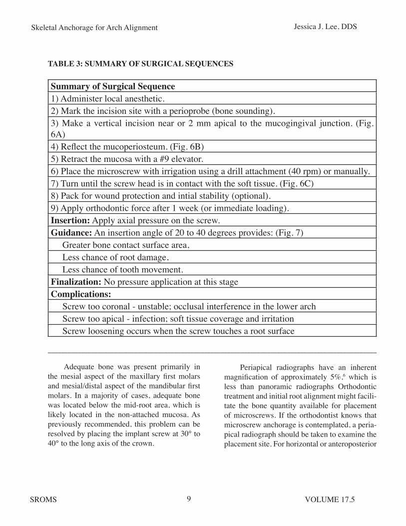
TABLE 3: SUMMARY OF SURGICAL SEQUENCES
___________________________________________________________________________________________________
Adequate bone was present primarily in the mesial aspect of the maxillary first molars and mesial/distal aspect of the mandibular first molars. In a majority of cases, adequate bone was located below the mid-root area, which is likely located in the non-attached mucosa. As previously recommended, this problem can be resolved by placing the implant screw at 30° to 40° to the long axis of the crown.
Periapical radiographs have an inherent magnification of approximately 5%,6 which is less than panoramic radiographs Orthodontic treatment and initial root alignment might facili-tate the bone quantity available for placement of microscrews. If the orthodontist knows that microscrew anchorage is contemplated, a peria-pical radiograph should be taken to examine the placement site. For horizontal or anteroposterior
Summary of Surgical Sequence1) Administer local anesthetic.2) Mark the incision site with a perioprobe (bone sounding).3) Make a vertical incision near or 2 mm apical to the mucogingival junction. (Fig. 6A)4) Reflect the mucoperiosteum. (Fig. 6B)5) Retract the mucosa with a #9 elevator.6) Place the microscrew with irrigation using a drill attachment (40 rpm) or manually.7) Turn until the screw head is in contact with the soft tissue. (Fig. 6C)8) Pack for wound protection and intial stability (optional).9) Apply orthodontic force after 1 week (or immediate loading).Insertion: Apply axial pressure on the screw.Guidance: An insertion angle of 20 to 40 degrees provides: (Fig. 7) Greater bone contact surface area, Less chance of root damage, Less chance of tooth movement.Finalization: No pressure application at this stageComplications: Screw too coronal - unstable; occlusal interference in the lower arch Screw too apical - infection; soft tissue coverage and irritation Screw loosening occurs when the screw touches a root surface

Skeletal Anchorage for Arch Alignment Jessica J. Lee, DDS
SROMS VOLUME 17.510
Figure 7. A microscrew is inserted at 20-40 degrees, although 10-20 degrees are also acceptable. The insertion angle allows greater bone contact surface area, decreases the chance of root damage, and decreases the chance of potentially interfering with tooth movement. (Courtesy of Dr. H. S. Park)______________________________________________
movements the most frequent sites for micro-screws are mesial or distal to the first molar.
Microscrews can be loaded immediately following placement. Animal studies suggest that, even though they only partially osseointe-grated, the microscrews can give adequate sta-bility during treatment and be removed eas-ily after completion of treatment.5 Microscrews designed specifically for orthodontic anchorage have a special head design with an eyelet to allow placement of ligature hooks and wires at the time of placement. This feature enhances the access to the microscrew without a concern for soft tissue coverage over the microscrew.
Loading
Depending upon the clinical indica-tion and desired orthodontic force application, microscrews can be used for direct or indirect
anchorage. Direct anchorage refers to the attach-ment of microscrews directly to the teeth of the active segment for orthodontic tooth movement. An example would be a molar intrusion case in which the microscrew is attached directly to the molar teeth being intruded. Indirect anchorage refers to the attachment of the microscrews to the teeth in the reactive segment that is used to move the active segment. For example, in an anterior retraction case, teeth of the reactive posterior segment are “indirectly” stabilized by the microscrew, and this stabilized posteri-or segment is then used to retract the anterior segment.
Microscrews can be loaded immediately or shortly after placement. The primary source of microscrew’s stability is from cortical bone. For a thin cortex and low-density trabecular bone, immediate loading should be limited to about 50 cN of force. Depending on load quality and quantity, orthodontic force can be applied with-in 1 week of microscrew placement. For young-er patients (less than 15 years of age) or adult patients with decreased bone density, a longer wait time of 7-10 days or the use of a miniplate is recommended. When initial stability is ques-tionable, use of a nickel-titanium coil spring instead of an elastic chain is recommended because it delivers a lower loading force than elastic chains.
Miniplates
In cases where a longer-term, heavier anchorage is required, or where bone between the roots of the teeth is inadequate for safe placement of a microscrew, a miniplate with monocortical screws can be considered. Mini-plate anchorage devices are placed well away
Skeletal Anchorage for Arch Alignment Jessica J. Lee, DDS
SROMS VOLUME 17.511
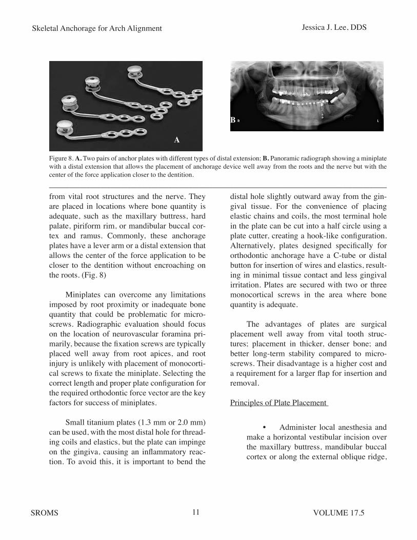
from vital root structures and the nerve. They are placed in locations where bone quantity is adequate, such as the maxillary buttress, hard palate, piriform rim, or mandibular buccal cor-tex and ramus. Commonly, these anchorage plates have a lever arm or a distal extension that allows the center of the force application to be closer to the dentition without encroaching on the roots. (Fig. 8)
Miniplates can overcome any limitations imposed by root proximity or inadequate bone quantity that could be problematic for micro-screws. Radiographic evaluation should focus on the location of neurovascular foramina pri-marily, because the fixation screws are typically placed well away from root apices, and root injury is unlikely with placement of monocorti-cal screws to fixate the miniplate. Selecting the correct length and proper plate configuration for the required orthodontic force vector are the key factors for success of miniplates.
Small titanium plates (1.3 mm or 2.0 mm) can be used, with the most distal hole for thread-ing coils and elastics, but the plate can impinge on the gingiva, causing an inflammatory reac-tion. To avoid this, it is important to bend the
Figure 8. A. Two pairs of anchor plates with different types of distal extension; B. Panoramic radiograph showing a miniplate with a distal extension that allows the placement of anchorage device well away from the roots and the nerve but with the center of the force application closer to the dentition.___________________________________________________________________________________________________
A
B
distal hole slightly outward away from the gin-gival tissue. For the convenience of placing elastic chains and coils, the most terminal hole in the plate can be cut into a half circle using a plate cutter, creating a hook-like configuration. Alternatively, plates designed specifically for orthodontic anchorage have a C-tube or distal button for insertion of wires and elastics, result-ing in minimal tissue contact and less gingival irritation. Plates are secured with two or three monocortical screws in the area where bone quantity is adequate.
The advantages of plates are surgical placement well away from vital tooth struc-tures; placement in thicker, denser bone; and better long-term stability compared to micro-screws. Their disadvantage is a higher cost and a requirement for a larger flap for insertion and removal.
Principles of Plate Placement
• Administer local anesthesia and make a horizontal vestibular incision over the maxillary buttress, mandibular buccal cortex or along the external oblique ridge,
Skeletal Anchorage for Arch Alignment Jessica J. Lee, DDS
SROMS VOLUME 17.512
depending on the projected location of the plate. It is important to make the incision within attached gingiva whenever pos-sible, typically 1 mm to 2 mm coronal to the mucogingival junction, depending on the available thickness of the attached gin-giva.
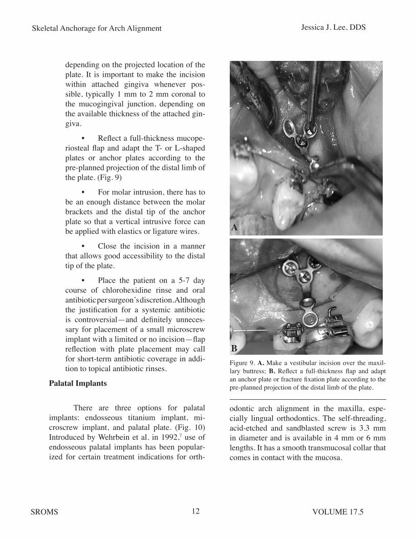
• Reflect a full-thickness mucope-riosteal flap and adapt the T- or L-shaped plates or anchor plates according to the pre-planned projection of the distal limb of the plate. (Fig. 9)
• For molar intrusion, there has to be an enough distance between the molar brackets and the distal tip of the anchor plate so that a vertical intrusive force can be applied with elastics or ligature wires.
• Close the incision in a manner that allows good accessibility to the distal tip of the plate.
• Place the patient on a 5-7 day course of chlorohexidine rinse and oral antibiotic per surgeon’s discretion. Although the justification for a systemic antibiotic is controversial—and definitely unneces-sary for placement of a small microscrew implant with a limited or no incision—flap reflection with plate placement may call for short-term antibiotic coverage in addi-tion to topical antibiotic rinses.
Palatal Implants
There are three options for palatal implants: endosseous titanium implant, mi-croscrew implant, and palatal plate. (Fig. 10) Introduced by Wehrbein et al. in 1992,7 use of endosseous palatal implants has been popular-ized for certain treatment indications for orth-
Figure 9. A. Make a vestibular incision over the maxil-lary buttress; B. Reflect a full-thickness flap and adapt an anchor plate or fracture fixation plate according to the pre-planned projection of the distal limb of the plate.______________________________________________
odontic arch alignment in the maxilla, espe-cially lingual orthodontics. The self-threading, acid-etched and sandblasted screw is 3.3 mm in diameter and is available in 4 mm or 6 mm lengths. It has a smooth transmucosal collar that comes in contact with the mucosa.
A
B
Skeletal Anchorage for Arch Alignment Jessica J. Lee, DDS
SROMS VOLUME 17.513
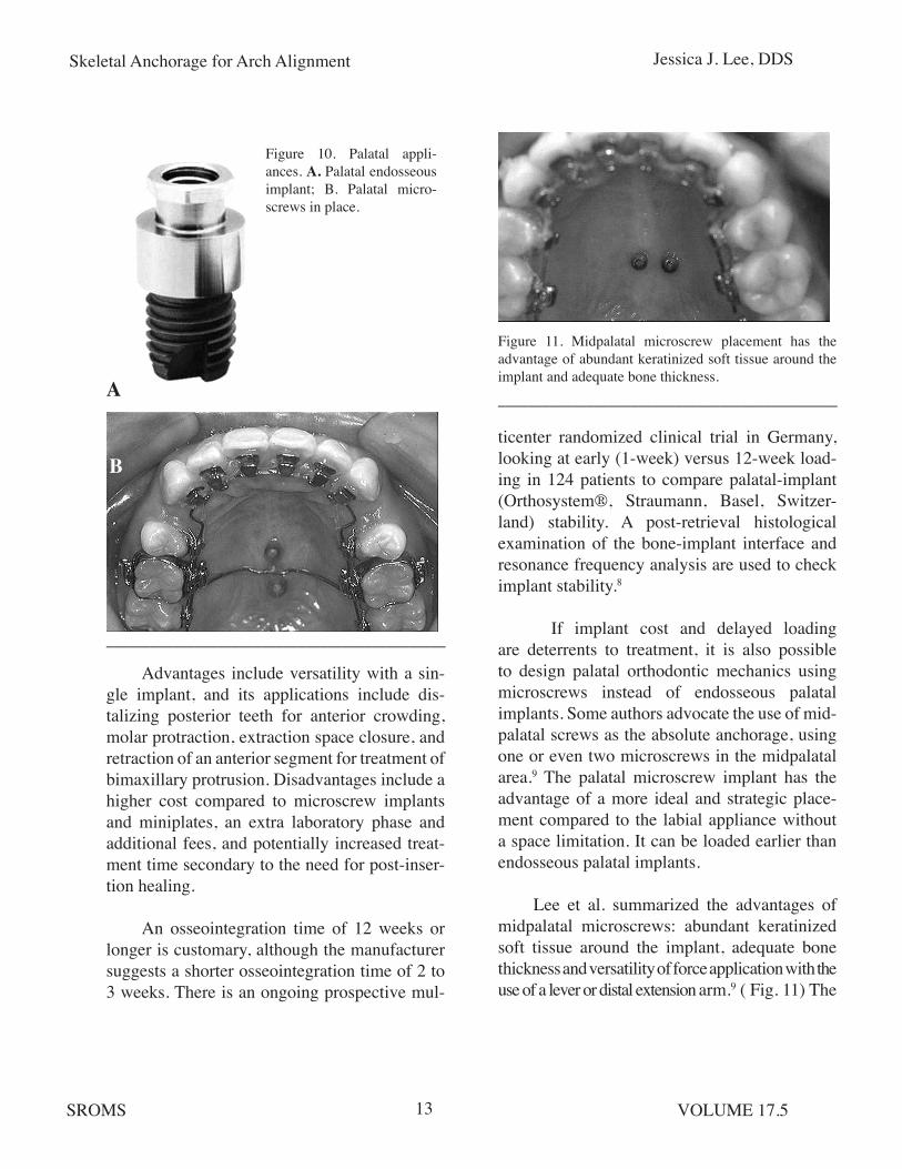
Figure 10. Palatal appli-ances. A. Palatal endosseous implant; B. Palatal micro-screws in place.
______________________________________________
Figure 11. Midpalatal microscrew placement has the advantage of abundant keratinized soft tissue around the implant and adequate bone thickness.______________________________________________
Advantages include versatility with a sin-gle implant, and its applications include dis-talizing posterior teeth for anterior crowding, molar protraction, extraction space closure, and retraction of an anterior segment for treatment of bimaxillary protrusion. Disadvantages include a higher cost compared to microscrew implants and miniplates, an extra laboratory phase and additional fees, and potentially increased treat-ment time secondary to the need for post-inser-tion healing.
An osseointegration time of 12 weeks or longer is customary, although the manufacturer suggests a shorter osseointegration time of 2 to 3 weeks. There is an ongoing prospective mul-
ticenter randomized clinical trial in Germany, looking at early (1-week) versus 12-week load-ing in 124 patients to compare palatal-implant (Orthosystem®, Straumann, Basel, Switzer-land) stability. A post-retrieval histological examination of the bone-implant interface and resonance frequency analysis are used to check implant stability.8
If implant cost and delayed loading are deterrents to treatment, it is also possible to design palatal orthodontic mechanics using microscrews instead of endosseous palatal implants. Some authors advocate the use of mid-palatal screws as the absolute anchorage, using one or even two microscrews in the midpalatal area.9 The palatal microscrew implant has the advantage of a more ideal and strategic place-ment compared to the labial appliance without a space limitation. It can be loaded earlier than endosseous palatal implants.
Lee et al. summarized the advantages of midpalatal microscrews: abundant keratinized soft tissue around the implant, adequate bone thickness and versatility of force application with the use of a lever or distal extension arm.9 ( Fig. 11) The
A
B

Skeletal Anchorage for Arch Alignment Jessica J. Lee, DDS
SROMS VOLUME 17.514
rationale for advocating a midpalatal location of the microscrew is based on its soft and hard tis-sue characteristics. Palatal soft tissue is two to three times thicker than the buccal mucosa, and there is a uniform soft tissue thickness of 1 mm in the mid-palatal area, 4 mm posterior to the incisive papilla. Cortical bone thickness here is also ideal for microscrew implants.
Palatal microscrews and endosseous pala-tal implant are both viable alternatives to con-ventional extraoral and transpalatal appliances, and in certain cases, can be used in lieu of, or in conjunction with, buccal microscrew implants. Use of miniplates in the palatal region is cer-tainly an option, although it is rarely requested by referring orthodontists and offers no distinc-tive advantage over less costly microscrews.
Principles of Palatal Implant Placement
A cephalometric radiograph or CT scan is useful to assess palatal bone thickness in the sagittal plane. The lower the angle between the ANS-PNS and implant axes, the more bone
Figure 12. The typical palatal implant diameter is 3.3 mm with a transmucosal collar (A) (2.5 or 4.5 mm width); abutment head with 5 mm healing cap (B); and retention screw (not shown).
______________________________________________
thickness is available. A deep palatal vault is not suitable for the connecting bar, which requires a minimum of 6 mm to 7 mm of transverse width. Typical implant diameter is 3.3 mm with self-tapping, acid-etched threads. There are four constituent parts to the palatal implant: transmu-cosal collar (2.5 or 4.5 mm depending on palatal mucosal thickness), abutment head, 5 mm heal-ing cap, and retention screw. (Fig. 12)
• Give palatine and incisive nerve blocks.
• Use a 4 mm to 5 mm diameter tissue punch to remove the mu- cosa
• Use a small round bur (1/2) to mark on the bone.
• Use a pilot drill to prepare the site for implant placement.
• Place the implant at an approxi- mately 60° angle to the occlusal plane.
• Place the healing cap.
The implant manufacturer recommends a healing period of 12 to 13 weeks, preferably
Figure 13. A transpalatal bar placed for the specific orth-odontic indication.
______________________________________________
Skeletal Anchorage for Arch Alignment Jessica J. Lee, DDS
SROMS VOLUME 17.515
with a prefabricated acrylic palatal stent cover-ing the implant for patient comfort and to keep the tongue away from the implant. The labora-tory phase occurs during the 10th week, when an impression is taken with the transfer cop-ing. The transpalatal bar, customized to specific orthodontic indication, is fabricated and deliv-ered to the patient. (Fig. 13) When the implant is ready for removal, a trephine bur can be used, but typically the implant can be removed with a manual wrench.
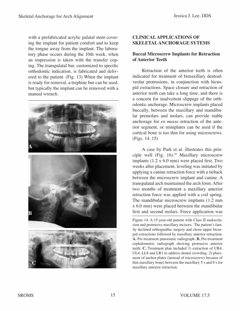
Figure 14. A 15-year-old patient with Class II malocclu-sion and protrusive maxillary incisors. The patient’s fam-ily declined orthognathic surgery and chose upper bicus-pid extractions followed by maxillary anterior retraction. A. Pre-treatment panoramic radiograph; B. Pre-treatment cephalometric radiograph showing protrusive anterior teeth; C. Treatment plan included 1) extraction of UR4, UL4, LL8 and LR1 to address dental crowding, 2) place-ment of anchor plates (instead of microscrews because of thin maxillary bone) between the maxillary 5’s and 6’s for maxillary anterior retraction.
A
B
C
CLINICAL APPLICATIONS OF SKELETAL ANCHORAGE SYTEMS
Buccal Microscrew Implants for Retraction of Anterior Teeth
Retraction of the anterior teeth is often indicated for treatment of bimaxillary dentoal-veolar protrusions, in conjunction with bicus-pid extractions. Space closure and retraction of anterior teeth can take a long time, and there is a concern for inadvertent slippage of the orth-odontic anchorage. Microscrew implants placed buccally, between the maxillary and mandibu-lar premolars and molars, can provide stable anchorage for en masse retraction of the ante-rior segment, or miniplates can be used if the cortical bone is too thin for using microscrews. (Figs. 14, 15)
A case by Park et al. illustrates this prin-ciple well (Fig. 16).10 Maxillary microscrew implants (1.2 x 6.0 mm) were placed first. Two weeks after placement, leveling was initiated by applying a canine retraction force with a tieback between the microscrew implant and canine. A transpalatal arch maintained the arch form. After two months of treatment a maxillary anterior retraction force was applied with a coil spring. The mandibular microscrew implants (1.2 mm x 6.0 mm) were placed between the mandibular first and second molars. Force application was
______________________________________________
______________________________________________

Skeletal Anchorage for Arch Alignment Jessica J. Lee, DDS
SROMS VOLUME 17.516
Figure 15: Progress records of same patient as in Figure 14 at age 17. Note the maxillary incisor retraction. An-chor plates were left in place for 18 months and remained stable until they were ready for removal. A. Intraoral view of maxillary miniplate; B. Post-treatment panoramic ra-diograph; C. Post-treatment lateral cephalogram.
______________________________________________
initiated two weeks after implant placement and the implants were tied to the mandibular arch wire with elastic thread.
An improvement in profile was evi-dent during the first 11 months of treatment. Cephalometric superimposition showed a bodily retraction of the maxillary anterior teeth and an uprighting of the mandibular molars. The maxil-lary posterior teeth moved slightly distally and had a small amount of extrusion. The mandibu-lar molars were uprighted and intruded slightly, resulting in upward and forward rotation of the mandible. In the maxilla, the force was applied near the center of resistance of the six anterior teeth to produce bodily intrusion and retrac-tion. Uprighting and intrusion of the mandibular molars resulted in upward and forward move-ment of the chin.
Palatal Microscrew Implants for Anterior Teeth Retraction
Hong et al. described a lever-arm- microscrew implant to provide anterior torque control for incisor retractions.11 The possible movements using this particular design include bodily movements and distalization with either intrusion or extrusion. To design the optimal lever-arm microscrew system that produces the desired force vector during retraction the implant manufacturer recommends a force application analysis based on a lateral cephlo-metric radiograph. Adjustment of the lever-arm and the position of the microscrew allow the desired line of retraction force with respect to the center of resistance.
The center of resistance for the six anterior teeth was defined by Vanden Bulcke et al.12 as 7 mm apical to the interproximal bone between the central incisors when measured perpendic-ular to the occlusal plane. The required length of the lever-arm and the position of the micro-screw are determined on a lateral cephalometric
A
B
C

Skeletal Anchorage for Arch Alignment Jessica J. Lee, DDS
SROMS VOLUME 17.517
Figure 16. An anterior retraction case using microscrews. (Courtesy of Dr. H. S. Park) A. Pretreatment records; B. Maxillary screws were placed following upper bicuspid extractions, and retraction force was applied with a coil spring; C. Mandibular microscrews were placed between the mandibular first and second molars. Implants were tied to the arch wire with elastic thread for uprighting of mandibular molars; D. Post-treatment records.
___________________________________________________________________________________________________
A
D
B
C
radiograph. The lever-arm is made of 0.9 mm stainless steel wire and is attached to the arch wire between the lateral incisors and canines. A microscrew is inserted through the mucosa without flap reflection. Proper implant length is determined by adding the depth of palatal mucosa and the thickness of the palatal bone at the projected site. In most instances, 6 mm screws or implants are used. Self-drilling screws can be used in most cases without a need for pilot drilling.
Wehrbein et al. described the use of a pala-tal anchorage system in six Class II patients in whom maxillary bicuspid extractions and inci-sor retractions were performed.7 None of the
patients required the use of class II elastics or headgear. The mean overjet was 9 mm. The duration of treatment was 12 months: 3 months of implant osseointegration and 9 months of active orthodontic treatment. These authors found implants to be stable throughout the treat-ment phase with favorable peri-implant soft tis-sue and no loss of anchorage during 8 mm of retraction of the anterior teeth.
The specific location of the microscrew or palatal implant insertion is dictated by bone availability, and the pre-planned site of anchor-age device should be discussed with the refer-ring orthodontist, who will determine the spe-

Skeletal Anchorage for Arch Alignment Jessica J. Lee, DDS
SROMS VOLUME 17.518
Figure 17: Use of microscrews to intrude the maxillary molars to the level of the occlusal plane and closure of an anterior open bite. (Courtesy of Dr. Y. C. Park) A. Right intraoral view of anterior open bite; B. Placement of microscrews apical to the molars for intrusion of the molars; C. Right intraoral view of treated open bite.
cific design of the lever-arms for applying the desired orthodontic forces.
Use of Miniplates in Anterior Open Bite Closure
Anterior open bite poses a difficult chal-lenge to orthodontists and surgeons in terms of proper correction and post-treatment retention, and deserves special attention. Various orth-odontic appliances alone or in conjunction with surgical procedures (e.g., LeFort I osteotomy, posterior maxillary segmental osteotomy, and mandibular osteotomy) provide means of cor-recting anterior open bite. Absolute anchorage can be utilized by orthodontists to level the arch prior to surgical correction of anterior open bite, or it can be used effectively for treatment of cer-tain open bite cases that are dentoalveolar in ori-gin. (Fig. 17)
Sherwood et al. reported the use of mini-plates as a skeletal anchorage for closure of anterior open bite without extrusion of the anterior teeth.13 Compared to the microscrew, a slightly larger flap was required, but the mini-plate can be placed in sound bone, well away from the roots of the teeth, providing a superior strength over microscrews on a long-term basis. Microscrews are placed in both maxillary and mandibular arches to intrude the molars.
Erverdi et al. reported on 10 patients, ages between 17-23 years, with anterior open bite and posterior maxillary excess treated using titani-um miniplates fixated in the zygomatic buttress area.14 Force was applied bilaterally with coil springs between the vertical limb of the mini-plate and the first molar buccal tube. They found that, on average, maxillary posterior teeth were intruded in 5.1 months, and the mean total treat-
______________________________________________
A
B
C
ment time was 18.3 months. The mean change in overjet was -2.0 mm and in overbite was +3.7 mm, brought about by 2.6 mm of maxillary molar intrusion, 1.1 mm of maxillary and man-dibular incisor extrusion, and 3.1° of rotation of the mandible. They concluded that approxi-mately 40% of the anterior open bite correction was achieved with autorotation of the mandible and 60% with extrusion of the incisors.
As stated previously, a high-mandibu-lar plane angle is a risk factor for failure of

Skeletal Anchorage for Arch Alignment Jessica J. Lee, DDS
SROMS VOLUME 17.519
microscrews, because such cases typically hav-ing thinner cortical bone. Use of either bigger diameter screws (2.3 mm) or miniplates may improve stability in high mandibular plane angle cases.
To generate a vertical intrusive force on the molars, the power chains or elastics could be connected from the middle of the arch wire between the molars to a miniplate, supplement-ed with a microscrew implant in the palatal aspect between the molars. A vector of intrusive force has to pass through the center of resistance located in the interproximal bone between the two molars. A constant loading within the force range of 150 g to 200 g can ensure the proper intrusion and appropriate bone remodeling in response to intrusive loading.14
FACTORS ASSOCIATED WITH STABILITY OF MICROSCREWS
Miyawaki et al. reported that a 1.0 mm screw diameter was associated with a signifi-cantly lower success rate compared to larger screws, with a 1.5 mm or 2.3 mm diameter, or to miniplates.15 A high mandibular plane angle and inflammation of the peri-implant tissue were risk factors for premature instability of the screws. Screw length, immediate loading, location of implant placement, age, sex, and dental crowd-ing were not correlated with implant instability.
Both surgeons and orthodontists have asked whether the microscrews remain station-ary under orthodontic forces. In a human clini-cal trial, microscrews were inserted in the max-illary buttress for retraction of anterior teeth.16 Orthodontic force application was initiated two weeks after insertion of the microscrews. Although there was no clinical mobility of the
microscrews, they did tip forward by 0.4 mm at the screw head. The microscrews were extruded and tipped by 1.0 mm to 1.5 mm in 7 of the 16 patients, indicating that the microscrews do not remain absolutely stationary throughout orth-odontic loading.
Concern is often expressed about the microscrews impinging on vital structures such as blood vessels and nerves. A recent study in dogs showed that molar intrusion of 3.4 mm over 7 months did not result in any damage to the inferior alveolar nerve or surrounding blood vessels.17 Root resorption was observed but was repaired with new cementum. There was no sta-tistically significant difference in root length before or after the intrusion for the 4-month or the 7-month groups. The mean amount of root resorption was 0.1 +/- 0.1 mm during the 7-month treatment time. Force-loaded mini-plates showed a denser bone-to-implant inter-face than unloaded controls, indicatin histologi-cally stable osseointegration under orthodontic force application.17
What effect, if any, does molar intrusion with miniplates have on the vitality of the pulp tissue? Konno et al. reported on morphologic and hemodynamic analysis of dental pulp in dogs after molar intrusion with miniplates.18 Histological examination of the dental pulp after 4-months of intrusion showed slight, reversible degenerative changes, but the pulpal blood flow and neurological responses were maintained during the intrusion phase.
Cheng et al. conducted a prospective inves-tigation of 140 microscrews and miniplates in 44 patients.19 Microscrews of 2 mm diameter and 5 mm to 15 mm lengths were used for applica-tion of various orthodontic forces, initiated 2 to
Skeletal Anchorage for Arch Alignment Jessica J. Lee, DDS
SROMS VOLUME 17.520
4 weeks after surgery. The majority of implants were placed in the posterior maxilla, with fewer placed in the posterior mandible. The cumulative survival rate was 89% (125/140). Interestingly, there was no significant difference between the microscrews and miniplates. The location of the implant and the condition of the soft tissue at the implant emergence interface were found to be significant predictors of implant stability. Implants in the posterior mandible and those sur-rounded by nonkeratinized mucosa had a higher tendency for failure and infection around the implant. Implants in the posterior maxilla and those surrounded by keratinized tissue survived longer than those in the posterior mandible and surrounded by a smaller amount of keratinized tissue.
In this study, the length of microscrews had no effect on implant survival. Longer implants did not result in better bone support. A load in the range of 100 g to 200 g could be handled by the microscrews and miniplates, and the magnitude of the load did not affect the implant failure rate. The study also found a correlation between bac-terial contamination, due to poor oral hygiene, and implant failure, i.e., peri-implant infection was associated with a high rate of implant fail-ure.
Clinically, micro-mobility during micro-screw implant insertion appears to affect at least the early stability. The bone-to-implant interface should be less than 0.2 mm, and the best way to prevent a gap formation between the implant threads and surrounding bone is to minimize wobbling and maintain a firm axial pressure when the microscrew is placed. If pilot drilling is necessary, the surface temperature of the bone should not exceed 39°C, as alkaline phosphate in the bone is subject to thermal damage if the sur-
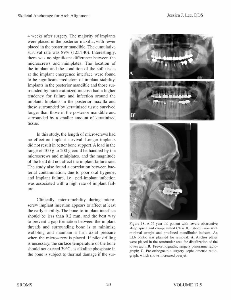
Figure 18. A 55-year-old patient with severe obstructive sleep apnea and compensated Class II malocclusion with minimal overjet and proclined mandibular incisors. An LL6 pontic was planned for removal; A. Anchor plates were placed in the retromolar area for distalization of the lower arch; B. Pre-orthognathic surgery panoramic radio-graph; C. Pre-orthognathic surgery cephalometric radio-graph, which shows increased overjet.
A
B
C

Skeletal Anchorage for Arch Alignment Jessica J. Lee, DDS
SROMS VOLUME 17.521
Figure 19. A 15-year-old patient with dental crowding and mesial drift of the LR posterior segment. A. Intraopera-tive photo. Anchor plate with the longest distal extension had to be used to overcome the thickness and laxity of the surrounding soft tissue; B. Post-op panoramic radio-graph; C. 12 months post-op. Patient had difficult access to maintain oral hygiene around the distal extension of the plate, mainly due to the thickness of the retromolar soft tissue covering the distal extension of the plate; D. - E. Occlusal results were satisfactory and the plate was ready for removal. Although patient had difficult access to maintain adequate hygiene around the plate, all screws were found to be stable and there was no evidence of infection at the time of removal. _____________________________________________________________________________________________________
face temperature is 47°C for more than 1 minute and 43°C for more than 5 minutes.
Although these numbers may not be entirely applicable to microscrew implants, which do not require a complete osseointegration, copi-ous irrigation during drilling and minimizing the bone gap with controlled implant insertion can facilitate bone formation and hence the early
stability of microscrews. This may also be less critical for placement of miniplates and the fixa-tion screws that hold the miniplates, but proper surgical techniques and site selection still have a significant influence on the long-term stability of miniplates.
Most importantly, longevity of miniplates is also dependent on the condition of the kera-
A
B
C
D
E
Skeletal Anchorage for Arch Alignment Jessica J. Lee, DDS
SROMS VOLUME 17.522
tinized tissue around the implant and mainte-nance of good oral hygiene to prevent tissue inflammation. This is especially true when clini-cal indications call for miniplate placement in the retromolar pad area, where tissue thickness can interfere with proper oral hygiene. (Figs. 18, 19)
COMPLICATIONS OF MICROSCREWS AND MINIPLATES
Potential complications of microscrew implants and miniplates include soft tissue irri-tation, infection, premature loosening of screws, and root injury. The latter two problems are more common with microscrews than miniplates. The single most common complication with mini-plates is tissue overgrowth over the distal end of the plate, especially when the distal portion of the plate was not bent properly and impinges on the tissue.
Chen et al. followed 359 miniplates and 129 microscrews, and found that sex, type of malocclusion, screw length, local or full-arch treatment, loading pattern, and duration of heal-ing time all had no significant effect on failure.20 However, they noted a higher rate of failure in younger patients, when placement was in the mandibular arch, during retraction or pro-traction cases, when placement was anterior to second bicuspids, and for microscrews versus miniplates.
Another study reviewed 140 microscrew implants (41 in maxilla / 99 in mandible) in 98 patients.21 Implants were immediately loaded with 50cN coil springs. Orthodontic movements included molar uprighting, molar uprighting and mesial movement, molar mesial movement, incisor intrusion/proclination, incisor retraction,
premolar intrusion, midline correction, premo-lar distal movement, and molar intrusion. Suc-cess was defined by complete absence of mobil-ity after 120 days of continuous loading. Partial failure was defined as minimum mobility after 120 days of continuous loading, even though the implants resisted further load without com-plete loosening. Complete failure meant the loss of implants. Results showed 13 complete fail-ures (9.3%) and 9 partial failures (6.4%). The maxillary failure rate (12.2%) was higher than the mandibular failure rate (8.0%). Palatal slope was associated with the greatest risk of failure, and placement in the mandibular alveolar pro-cess had the lowest failure rate. Potential causes of implant failure were attributed to tissue inflammation, low bone density, thick mucosa, and incorrect surgical procedure.21
Teeth are not moved following root dam-age, but additional movement and orthodontic force application can potentially exacerbate the situation, exceeding the tooth’s innate capacity to heal the cementum injury. Movement of a tooth into contact with a TAD is a concern but has not been reported in the literature or observed clini-cally. A general formula for the safe root-to-root distance is 5.5 mm based on the following cal-culation:
1.5 MM SCREW DIAMETER + (1.5 MM X 2 BONE) + (0.5 MM X 2 PDL)
If the root-to-root distance is less than 5.5 mm, then the surgeon should ask the orthodontist to flare the roots farther, position the screws more apically or consider using mini-plates to avoid the roots and vital structures all together. Based on my clinical experience and a review of randomly-selected 45 microscrews and 33 miniplates, a higher failure was noted in
Skeletal Anchorage for Arch Alignment Jessica J. Lee, DDS
SROMS VOLUME 17.523
the maxilla: 4 microscrews loosened and 1 mini-plate got infected.
Interestingly, the infected plate was par-tially covered by bone 6 months after placement and did not display any mobility, even though 2 out of 3 screws were loose. The plate was left in place, the wound irrigated, and the loose screws were replaced by larger-diameter screws. The plate remained without further infection or instability until it was removed after treatment completion.
For the management of infected mi-croscrews and miniplates, debridement, oral antibiotic rinses, and judicious use of systemic antibiotic are the treatment of choice. Implants do not have to be removed as long as there is no evidence of infection and have less than class I mobility. If the implant has to be removed, allow 4 to 6 weeks of healing before placing a new microscrew. All microscrew failures occurred in patients younger than 15 years, and this can be avoided by the use of miniplates in younger patients where the bone density is less than that of adults.
Nowadays, many microscrews are placed by the orthodontists in their offices, and the majority of cases referred to oral and maxillo-facial surgeons are those requiring miniplates, younger patients who may not tolerate surgical procedures under local anesthesia alone, and cases in which microscrews need to be removed due to infection or loosening. It is reasonable to consider miniplates after the first failure of microscrews, but unfortunately, orthodontists are often reluctant to refer patients to surgeons after the first failure, and they make repeated attempts thereafter to place new microscrews, leading to a loss of patient confidence in the
viability of the treatment plan and ultimately a higher cost to the patient.
CONCLUSIONS
Microscrews and miniplates (collective-ly referred to as temporary anchorage devic-es or TADs) are widely used for orthodontic mechanics where absolute anchorage control is required. Their versatile clinical applications can be used for conventional orthodontics as well as combined orthodontic-orthognathic surgical treatments. Microscrews and miniplates have different indications and inherent strengths and weaknesses, and surgeons must select the prop-er type of implant to provide stable anchorage devices that withstand orthodontic forces. The force requirement, age of the patient, bone den-sity, and anatomic considerations should guide the use of microscrews versus miniplates. Care-ful planning based on close communications between orthodontists and surgeons, proper surgical placement, and maintaining the health of the peri-implant soft tissues are the most sig-nificant factors determining the success of this versatile treatment modality.

Skeletal Anchorage for Arch Alignment Jessica J. Lee, DDS
SROMS VOLUME 17.524
REFERENCES
1. Creekmore TD and Eklund MK: The possi-bility of skeletal anchorage. J Clin Orthod; 17:266, 1983.
2. Fritz U, Ehmer A and Diedrich P: Clini-cal suitability of titanium microscrews for orthodontic anchorage-preliminary experi-ences. J Orofac Orthop; 65:410, 2004.
3. Park HS and Kwon TG: Sliding mechanics with microscrew implant anchorage. Angle Orthod; 74:703, 2004.
4. Schnelle MA, Beck FM, Jaynes RM et al: A radiographic evaluation of the availabil-ity of bone for placement of miniscrews. Angle Orthod; 74:832, 2004.
5. Ohmae M, Saito S, Morohashi T, et al: A clinical and histological evaluation of titanium mini-implants as anchors for orth-odontic intrusion in the beagle dog. Am J Orthod Dentofacial Orthop; 119:489, 2001.
6. Larheim TA and Eggen S: Determination of tooth length with a standardized parallel-ing technique and calibrated radiographic measuring film. Oral Surg Oral Med Oral Pathol; 48:374, 1979.
7. Wehrbein H, Glatzmaier J, Mundwiller U et al: The Orthosystem-a new implant sys-tem for orthodontic anchorage in the pal-ate. J Orofac Orthop; 57:142, 1996.
Dr. Jessica Lee received her DDS from the University of Washington School of Dentistry and oral and maxillofacial surgery training from the University of Washington (UW) in Seattle. She completed a fellowship in orthognathic sur-gery at the Swedish Medical Center. She then became Assistant Professor and Residency Pro-gram Director in oral and maxillofacial surgery at the UW and maintains an orthognathic surgery practice at the Swedish Medical Center, where she is the Rotation Director/Attending Surgeon for UW OMS residents. Dr. Lee specializes in orthognathic surgery and dentofacial defor-mities, and works closely with both the OMS and Orthodontics programs at the University of Washington. She has written multiple book chapters on the topics above and presented her lectures nationally and internationally, with spe-cial emphasis on orthognathic surgery and sur-gical protocols for temporary anchorage devices (TAD).
Skeletal Anchorage for Arch Alignment Jessica J. Lee, DDS
SROMS VOLUME 17.525
8. Jung BA, Wehrbein H, Hopfenmuller W, et al: Early loading of palatal implants (ortho-type II): A prospective multicenter random-ized controlled clinical trial. Trial;8:24, 2007.
9. Lee JS, Kim DH, Park YC, etal: The effi-cient use of midpalatal miniscrew implants. Angle Orthod; 74:711, 2004.
10. Park HS, Bae SM, Kyung HM et al: Micro-implant anchorage for treatment of skeletal Class I bialveolar protrusion. J Clin Orthod; 35:417, 2001.
11. Hong RK, Heo JM and Ha YK: Lever-arm and mini-implant system for anterior torque control during retraction in lingual orth-odontic treatment. Angle Orthod; 75:129, 2004.
12. Vanden Bulcke PJ: Center of resistance for anterior retraction. Angle Orthod; 65:110, 1994.
13. Sherwood KH, Burch JG and Thompson WJ: Closing anterior open bites by intrud-ing molars with titanium miniplate anchor-age. Am J Orthod Dentofacial Orthop; 122:593, 2002.
14. Erverdi N, Keles A and Nanda R: The use of skeletal anchorage in open bite treatment: A cephalometric evaluation. Angle Orthod; 74:381, 2004.
15. Miyawaki S, Koyama I, Inoue M, et al: Fac-tors associated with the stability of tita-nium screws placed in the posterior region for orthodontic anchorage. Am J Orthod Dentofacial Orthop; 124:373, 2003.
16. Liou EJW, Pai BCJ and Lin JCY: Do minis-crews remain stationary underorthodontic forces? Am J Orthod Dentofacial Orthop; 126:42, 2004.
17. Daimaruya T, Hiroshi N, Umemori M, et al: The influences of molar intrusion on the inferior alveolar neurovascular bundle and root using the skeletal anchorage system in dogs. The Angle Orthodontist; 71:60, 2001.
18. Konno Y, Daimaruya T, Iikubo M et al: Morphologic and hemodynamic analysis of dental pulp in dogs after molar intru-sion with the skeletal anchorage system. Am J Orthod Dentofacial Orthop; 132:199, 2007.
19. Cheng SJ, Tseng IY, Lee JJ, et al: A prospec-tive study of the risk factors associated with failure of mini-implants used for orth-odontic anchorage. Int J Oral Maxillofac Implants; 19:100, 2004.
20. Chen YJ, Chang HH, Huang CY, et al: A retrospective analysis of the failure rate of three different orthodontic skeletal an-chorage systems. Clinical Oral Implants Research; 18:768, 2007.
21. Luzi C, Verna C and Melsen B: A prospec-tive clinical investigation of the failure rate of immediately loaded mini-implants used for orthodontic anchorage. Prog Orthod; 8:192, 2007.