singular plastic fields in wedge indentation of pressure sensitive solids
TRANSCRIPT

Singular plastic fields in wedge indentation of pressuresensitive solids
Panos Papanastasiou a,*, David Durban b, Brian Lenoach c
a Civil and Environmental Engineering, University of Cyprus, Nicosia 1678, Cyprusb Faculty of Aerospace Engineering, Technion, Haifa 32000, Israelc Schlumberger Cambridge Research, Cambridge CB3 0EL, UK
Received 13 February 2002; received in revised form 25 November 2002
Abstract
The paper examines singular plastic fields induced near the tip of a wedge indentating a pressure sensitive solid. Plane
strain conditions are assumed and material response is modelled by the small strain Drucker–Prager rigid/plastic
constitutive law. A standard separation of variables solution is numerically generated for pure power-law hardening.
Three possible measures of wall roughness are studied with an attempt to expose the coupling between wall friction and
material pressure sensitivity. Sample calculations illustrate that stress singularity decreases with increasing friction,
wedge angle and hardening exponent, but increases with pressure sensitivity. At large values of the hardening exponent,
when the material is nearly perfectly plastic, effective stress contours approach the slip line limit. The concept of in-
dentation index is introduced as a possible estimate for average indentation pressure.
� 2003 Elsevier Science Ltd. All rights reserved.
Keywords: Wedge indentation; Pressure sensitive plasticity
1. Introduction
Wedge indentation processes in pressure sensitive plastic solids are encountered in numerous engineering
applications ranging from geotechnical problems (pile foundations design, excavations) to sintered powder
metals response in impact and penetration. However, while a considerable body of knowledge exists for
wedges indentating metals, much less is available for the indenting process of porous materials. Two recent
studies (Huang et al., 1998; Tordesillas and Shi, 1998) have examined and reviewed the wedge indentation
process for the Mohr–Coulomb perfectly plastic solid. Interest in such a study arises from modelling hy-
draulic fracturing in soft rocks; a technique employed in oil industry to stimulate production of hydro-carbons by creating fractures around a wellbore (Papanastasiou, 1999). There is also considerable interest
in the microelectronic industry in deformation and fracture of porous low-k dielectric films. Polymers are
International Journal of Solids and Structures 40 (2003) 2521–2534
www.elsevier.com/locate/ijsolstr
* Corresponding author. Tel.: +357-22-892292; fax: +357-22-892254.
E-mail address: [email protected] (P. Papanastasiou).
0020-7683/03/$ - see front matter � 2003 Elsevier Science Ltd. All rights reserved.
doi:10.1016/S0020-7683(03)00019-2

pressure sensitive and can be modelled as viscoplastic solids below their glass transition temperature. An
interesting study of microwedge indentation delamination has been given in De Boer and Gerberich (1996).
In this paper we use the rigid/plastic Drucker–Prager material model, formulated as a small strain de-
formation theory in conjunction with pure power-law response, to investigate near tip singular fields inwedge indentation. Concentrating on symmetric fields, with a plane strain pattern, we begin with an ei-
genvalue formulation for circumferential profiles of stresses and displacements. Wall friction is imple-
mented in boundary data by three different, yet equivalent, laws employing the Coulomb friction coefficient
f , the Prandtl friction factor m and a porosity friction factor q. These three measures of surface roughness
are interrelated by a simple formula, and it turns out that while m is bounded by an upper limit, both f and
q admit lower limits. For given m the corresponding values of ðf ; qÞ depend on wedge angle, hardening
index and pressure sensitivity. These findings are compatible with results for the Mises solid (Durban,
1999).Sample calculations illustrate that the level of stress singularity increases as the wedge becomes sharper
and smoother. Strain hardening causes an increase in the singularity of stresses. Examples of effective stress
contours indicate that with vanishing hardening, when the material approaches the perfectly plastic model,
contours of effective stress, near the tip, approach the slip lines of perfect plasticity.
It is suggested that the present analysis can be useful in providing a simple approximate assessment of
the average indentation pressure. To this end we have defined the indentation index in terms of singularity
level and friction measures. A few special cases are derived for the indentation index at different degrees of
approximation.
2. Near tip plastic field equations
With the notation of Fig. 1 we focus attention on the singular stress field which is expected to develop
near the tip of a rigid wedge indenting a plastic medium under plane strain conditions. Material response
within that singular plastic zone is given by the plastic branch of the associated Drucker–Prager solid
(Durban and Papanastasiou, 1997)
� ¼ �p3S
2q
�þ lI
3
�ð1Þ
where � is the small strain tensor, S is the stress deviator and I is the second order unit tensor. The effective
stress, re (identified with the plastic potential), is defined by
re ¼ qþ lrh ð2Þ
θwedge α
r
Fig. 1. Notation for plane strain wedge indentation.
2522 P. Papanastasiou et al. / International Journal of Solids and Structures 40 (2003) 2521–2534

with q and rh denoting the Mises effective stress and the hydrostatic stress, respectively, given by
q ¼ 3
2S � �S
� �1=2
rh ¼1
3I � �r S ¼ r � rhI ð3Þ
Pressure sensitivity is reflected by the parameter l with the Mises model recovered when l ¼ 0. The total
plastic strain in (1) is assumed to be a known function of the effective stress re, with the specific power law
employed in this study
�p ¼re
r0
� �n
ð4Þ
where both the hardening exponent n and reference stress r0 are material parameters determined experi-
mentally.Following standard practice of singular plastic field analysis, we examine separation of variables rep-
resentation of the stress components, within the near tip zone,
rr ¼ rs~rrr rh ¼ rs~rrh rrh ¼ rs~rrrh rz ¼ rs~rrz ð5Þwhere s (expected to be negative) is the stress singularity level to be determined, and the tilde marks cir-
cumferential stress profiles (eigenfunctions) associated with the eigenvalue s.Likewise, we shall use the separation of variables relations
q ¼ rs~qq rh ¼ rs~rrh re ¼ rs~rre ð6Þwhere, again, tilted quantities depend only on h.
The plane strain constraint requires that all of the z components of the strain tensor (1) vanish, hence
ð~rrz � ~rrhÞ þ2
9l~qq ¼ 0 ð7Þ
while the shear stress components in the z-plane are identically zero. Combining (7) with the definition of qin (3) we find that
~qq ¼ 1
mmax
~rrr � ~rrh
2
!224 þ ~rr2
rh
35
1=2
with mmax ¼1� l2=9
3
� �1=2
ð8Þ
and
~rrh ¼1
2ð~rrr þ ~rrhÞ �
l9~qq ð9Þ
Relations (8) and (9) give the circumferential profiles of the Mises stress and hydrostatic stress in terms of
plane components of stress. Parameter mmax, which will be discussed later, is the maximum local friction
factor in the sense that when ~rrrh ¼ �mmax~qq the entire Mises stress is activated by ~rrrh with ~rrr ¼ ~rrh. The
circumferential profile of the effective stress re follows in the form
~rre ¼ 3m2max~qqþ
l2ð~rrr þ ~rrhÞ ð10Þ
with ~qq given in (8). Plane strain deformation is maintained if, by (7) and (9),
~rrz ¼1
2ð~rrr þ ~rrhÞ �
l3~qq ð11Þ
The two equations of equilibrium, written in polar coordinates, for the plane components of stress,become in view of (5)
~rr0rh þ ðsþ 1Þ~rrr � ~rrh ¼ 0 ð12Þ
P. Papanastasiou et al. / International Journal of Solids and Structures 40 (2003) 2521–2534 2523

~rr0h þ ðsþ 2Þ~rrrh ¼ 0 ð13Þ
where the prime denotes differentiation with respect to h.Turning to strains and displacements, we note from (4) and (6) that the total plastic strain can be written
as
�p ¼ krns~rrne with k ¼ r�n
0 ð14Þ
We expect therefore that the ðr; hÞ components of the displacement––denoted by ðu; vÞ, respectively––can be
represented, within the singular zone, as
u ¼ krnsþ1~uu v ¼ krnsþ1~vv ð15Þ
where ð~uu; ~vvÞ are the circumferential profiles of the displacements.
Finally, we insert the stresses (5), (6) and the displacements (15) in the tensorial constitutive relation (1).
This gives, with the aid of (9), the three scalar equations
ðnsþ 1Þ~uu ¼ ~rrne
3
2~qq~rrr � ~rrh
2
!"þ l
2
#ð16Þ
~uuþ ~vv0 ¼ ~rrne
3
2~qq~rrh � ~rrr
2
!"þ l
2
#ð17Þ
1
2ð~uu0 þ ns~vvÞ ¼ ~rrn
e
3
2~qq~rrrh
� �ð18Þ
Thus, the governing system consists of five equations (12), (13) and (16)–(18), with five unknown
functions (three stress components and two displacements). The expressions for ~qq and ~rre are given in (8)
and (10) in algebraic form which, in fact, leaves us with a coupled system, of homogeneous ordinary dif-
ferential equations, of the fourth order.To complete the formulation we need four boundary conditions for the field variables. To this end we
assume a symmetric pattern of indentation with equal friction along the walls h ¼ �ðp � aÞ. The kinematic
boundary condition
~vv ¼ 0 at h ¼ �ðp � aÞ ð19Þ
is quite obvious, but it is less clear what friction condition should be imposed at the walls. One possibility is
to take the Coulomb friction law (accounting for stresses sign convention and expecting ~rrh to be negativealong the walls)
~rrrh ¼ �f ~rrh at h ¼ �ðp � aÞ ð20Þ
where f the Coulomb friction coefficient. However, in plastic forming processes (Durban, 1999) it is cus-
tomary to model surface frictional contact with the Prandtl friction factor m which determines the relative
contribution of surface shear stress to the effective Mises stress,
~rrrh ¼ �m~qq at h ¼ �ðp � aÞ ð21Þ
Combining that condition with (8) we find that for a perfectly rough wall the friction factor m attains its
highest possible value
m ¼ mmax ¼1� l2=9
3
� �1=2
ð22Þ
2524 P. Papanastasiou et al. / International Journal of Solids and Structures 40 (2003) 2521–2534

In the same spirit we may consider the porosity friction factor q through the wall friction law
~rrrh ¼ �q~rre at h ¼ �ðp � aÞ ð23Þ
with the effective stress given by (10). Thus, while the friction factor m reflects the influence of plasticity on
wall friction, we may regard the porosity friction factor q as a measure of the coupling between pressure
sensitivity, level of plastification and wall friction. Of course, for the Mises solid ðl ¼ 0Þ where ~rre ¼ ~qq we
have q m.Put differently, we have from (21) and (23) that along the walls of the indentor
m~qq ¼ q~rre ð24ÞCombining that relation with (9) and (10) gives the hydrostatic stress at the walls
l~rrh ¼m� qm
�~rre ð25Þ
implying a compressive hydrostatic environment when q > m.It is instructive to examine the relations between the three measures of friction ðf ;m; qÞ as defined in (20),
(21) and (23). To this end, we note from (8) and (21) that
~rrr � ~rrh
2¼ ðm2
max � m2Þ1=2~qq at h ¼ �ðp � aÞ ð26Þ
where, in accordance with numerical observations and the physics of the problem, we have taken the
positive root in (26). Eliminating now ~rrr between (10) and (26), and using (20) and (21) with (24), gives the
following relation among the three measures of friction
q ¼ mf
½3m2max þ lðm2
max � m2Þ1=2�f � lmð27Þ
The friction factor m varies in the range 06m6mmax. For a smooth wall both f and q will vanish as well,
while for a perfectly rough wall we find from (27)
0 0.2 0.4 0.6 0.8 10
0.1
0.2
0.3
0.4
0.5
0.6
0.7
0.8
0.9
1
f
m=0.1
m=0.2
m=0.3
m=0.4
µ =1µ =0.5
Fig. 2. Permissible pairs of Coulomb friction coefficient f and porosity friction q, at different levels of Prandtl friction factor m, forl ¼ 0:5 and l ¼ 1. A compressive hydrostatic environment exists for q > m.
P. Papanastasiou et al. / International Journal of Solids and Structures 40 (2003) 2521–2534 2525

q ¼ f3mmaxf � l
ð28Þ
providing the lower bound l=3mmax on the Coulomb friction coefficient, and the lower bound 1=3mmax onthe porosity friction factor. Likewise, we have from (27) the two lower bounds
f >lm
3m2max þ lðm2
max � m2Þ1=2q >
m
3m2max þ lðm2
max � m2Þ1=2ð29Þ
for any permissible value of the friction factor m.Fig. 2 displays typical curves for permissible pairs ðf ; qÞ at different levels of l and m. The lower bounds
(29) can be recognized as the asymptotes of the hyperbola (27) when either q or f become very large.
Specific pairs ðf ; qÞ are determined by geometry ðaÞ, hardening ðnÞ, pressure sensitivity ðlÞ, and friction
factor ðmÞ.
3. Numerical results and discussion
The eigensystem (12), (13) and (16)–(18), along with the boundary conditions (19) and (21) has been
solved numerically. A Galerkin type finite element scheme has been employed to trace the strongest per-
missible stress singularity ð�sÞ along with the associated profiles of the field variables. It is clear that Eqs.(12) and (13), together with the axis boundary conditions
~vv ¼ 0 ~rrrh ¼ 0 at h ¼ 0 ð30Þimply that the pattern of indentation must be symmetric. Thus the principal stresses ~rrr and ~rrh are even
functions while the shear stress ~rrrh is an odd function. The domain of integration is from h ¼ 0 (which in
fact can be regarded as a smooth wall) to h ¼ p � a where conditions (19) and (21) have to be satisfied.
Boundedness of displacement components as r ! 0 and existence of stress singularities dictate the range
� 1
n< s < 0 ð31Þ
for the eigenvalues. All field variables have been scaled by imposing wall reference pressure ~rrhðp � aÞ ¼ �1.
Numerical results have been checked against Mises solid ðl ¼ 0Þ data detailed in Durban and Rand (1991).Fig. 3 displays the variation of the stress singularity with the pressure sensitivity parameter l for a wedge
with semiangle a ¼ 30� and smooth walls. It is clearly seen that the singularity level decreases with in-
creasing hardening exponent n and shows little sensitivity to the plastic parameter l. Also, as n increases,
the singularity approaches the lower bound in (31).
The influence of friction factor m on the singularity level is illustrated in Fig. 4, again for a semiangle of
a ¼ 30�, with two hardening exponents (n ¼ 1, 3) and for a few values of l. By comparison with Fig. 3 the
influence of l on s is more pronounced at higher values of wall friction. Recall that the friction factor mcannot exceed mmax of (22) which is 1=
ffiffiffi3
p¼ 0:577 for l ¼ 0 and 2
ffiffiffi2
p=3
ffiffiffi3
p¼ 0:544 for l ¼ 1. The main
observation from Fig. 4 is that wall friction reduces stress singularity, particularly at low values of the
hardening exponent.
As expected, sharper wedges (smaller a) induce stronger singularities in the near tip plastic zone (Fig. 5).
Furthermore, the curves in Fig. 5 suggest the existence of a critical wedge angle where the singularity
vanishes altogether (this happens approximately for a � 60� with m ¼ 0:5 and a � 90� with m ¼ 0). At the
other extreme, for very small wedge angles, the level of singularity in Fig. 5 is nearly independent of both mand l.
A comparison between the three measures of surface friction is given in Fig. 6 which shows the variationof f and q with m for a ‘‘linear’’ solid, with n ¼ 1, and wedge semiangle of a ¼ 30�. Both f and q increase
with m but while f decreases with l, the porosity friction factor q increases with l. A similar observation
2526 P. Papanastasiou et al. / International Journal of Solids and Structures 40 (2003) 2521–2534

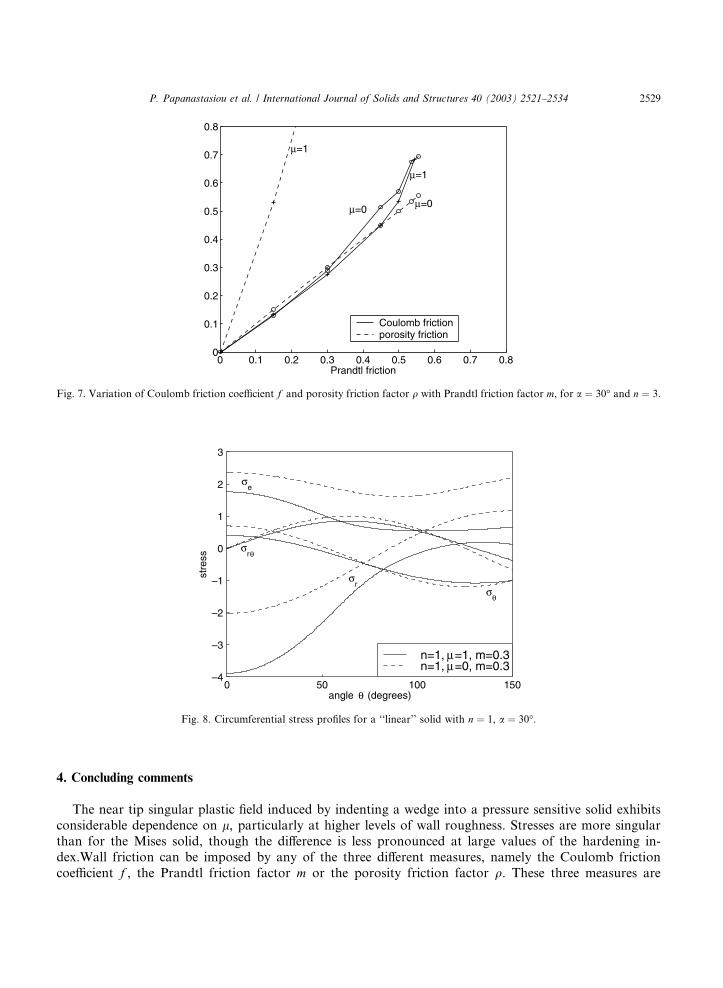
follows from Fig. 7 with n ¼ 3. Both figures are compatible with the friction chart of Fig. 2, and in all cases
q > m, ensuring by (25) a compressive hydrostatic environment. For l ¼ 0 we have in Figs. 6 and 7 the
straight lines q ¼ m of a Mises solid.
Illustrative examples of the stress profiles are shown in Fig. 8 for n ¼ 1 and in Fig. 9 for a nearly perfectly
plastic material with n ¼ 20. Displacement and strain profiles, with the same parameters as in Fig. 8 are
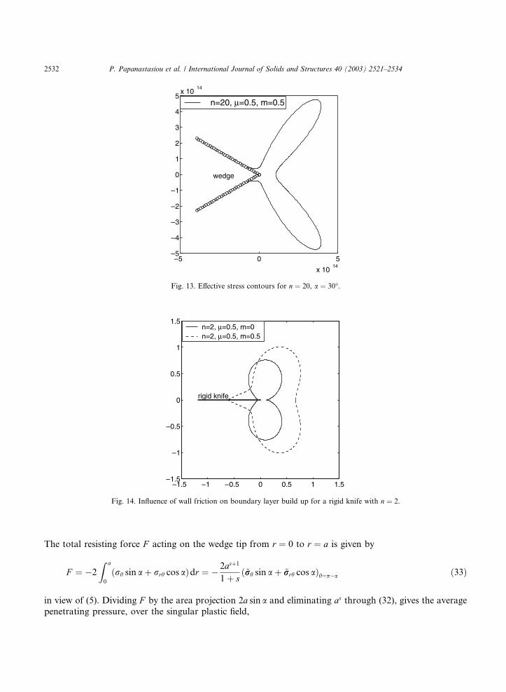
displayed in Figs. 10 and 11, respectively.Contours of constant effective stress are displayed in Figs. 12 and 13 for a wedge with a ¼ 30�. Notice the
decrease in size of the active plastic zone in Fig. 12 with increasing l. In Fig. 13, with n ¼ 20 the effective
0 0.2 0.4 0.6 0.8 1 1.2 1.40
0.1
0.2
0.3
0.4
0.5
0.6
0.7
0.8
0.9
1
µ
–s
n=1
n=2
n=3
n=10α=30o
m=0
Fig. 3. Variation of stress singularity s with pressure sensitivity l for a ¼ 30� and m ¼ 0.
0 0.1 0.2 0.3 0.4 0.5 0.6 0.70.1
0.2
0.3
0.4
0.5
0.6
0.7
0.8
0.9
m
–s
n=1, µ=1
n=1, µ=0.5
n=1,µ=0
n=3, µ=0
n=3, µ=1
α=30o
Fig. 4. Influence of friction factor m on singularity level s for a wedge with a ¼ 30�.
P. Papanastasiou et al. / International Journal of Solids and Structures 40 (2003) 2521–2534 2527

stress contour approaches the slip lines orientations of perfect plasticity ðn ! 1Þ. The decrease in size of
the active plastic zone in Fig. 13 is pronounced with the scaling of the axes by 10�14.The influence of wall friction on boundary layer build up is clearly shown in Fig. 14, for the case of
indentation by a rigid knife ða ¼ 0Þ. A strong wall roughness either increases the shear stresses or an ef-
fective Mode I component of the stress intensification leading to a larger plastic zone. At high levels of the
hardening exponent ðn ¼ 20Þ the slip line pattern is approached again with a friction boundary layer near
rough walls (Fig. 15).
0 20 40 60 80 1000
0.05
0.1
0.15
0.2
0.25
0.3
0.35
wedge angle α (degrees)
–s
n=3, µ=0, m=0n=3, µ=0, m=0.5n=3, µ=0.5, m=0n=3, µ=0.5, m=0.5
Fig. 5. Variation of stress singularity s with wedge angle a for n ¼ 3. Singularity vanishes at critical wedge angles.
0 0.1 0.2 0.3 0.4 0.5 0.6 0.70
0.2
0.4
0.6
0.8
1
1.2
1.4
Prandtl friction
µ=1
µ=1 µ=0
µ=0
µ=0.5
µ=0.5
α=30o
n=1Coulomb frictionporosity friction
Fig. 6. Variation of Coulomb friction coefficient f and porosity friction factor q with Prandtl friction factor m, for a ¼ 30� and n ¼ 1.
2528 P. Papanastasiou et al. / International Journal of Solids and Structures 40 (2003) 2521–2534
4. Concluding comments
The near tip singular plastic field induced by indenting a wedge into a pressure sensitive solid exhibits
considerable dependence on l, particularly at higher levels of wall roughness. Stresses are more singularthan for the Mises solid, though the difference is less pronounced at large values of the hardening in-
dex.Wall friction can be imposed by any of the three different measures, namely the Coulomb friction
coefficient f , the Prandtl friction factor m or the porosity friction factor q. These three measures are
0 0.1 0.2 0.3 0.4 0.5 0.6 0.7 0.80
0.1
0.2
0.3
0.4
0.5
0.6
0.7
0.8
Prandtl friction
µ=1
µ=1
µ=0 µ=0
Coulomb frictionporosity friction
Fig. 7. Variation of Coulomb friction coefficient f and porosity friction factor q with Prandtl friction factor m, for a ¼ 30� and n ¼ 3.
0 50 100 150–4
–3
–2
–1
0
1
2
3
angle (degrees)
stre
ss
σθ
θ
θ
σe
σr
σr
n=1, µ=1, m=0.3n=1, µ=0, m=0.3
Fig. 8. Circumferential stress profiles for a ‘‘linear’’ solid with n ¼ 1, a ¼ 30�.
P. Papanastasiou et al. / International Journal of Solids and Structures 40 (2003) 2521–2534 2529

connected by relation (27) with the degenerate equality q ¼ m when l ¼ 0. In this study we have chosen the
Prandtl friction factor m as the prime parameter to describe surface friction. That measure has the ad-
vantage of being bounded by 06m6mmax, while both f and q can increase indefinitely. For given m, fappears to decrease with l while q increases with l.
For sufficiently low levels of friction, both f and q vary almost linearly with m and hydrostatic com-
pression is ensured by q > m. However, ahead of the wedge along the penetration axis ðh ¼ 0Þ the cir-
cumferential strain �h remains positive (Fig. 11).
0 50 100 150–1.5
–1
–0.5
0
0.5
1
angle θ (degrees)
stre
ss
σr
σr
σr
σθ
θσe
σe
n=20, µ =0.5, m=0.5n=20, µ =0.5, m=0
Fig. 9. Circumferential stress profiles for a nearly perfectly plastic solid with n ¼ 20, a ¼ 30�.
0 50 100 150–6
–4
–2
0
2
4
6
8
angle θ (degrees)
disp
lace
men
t
v
u
n=1, µ=1, m=0.3n=1, µ=0, m=0.3
Fig. 10. Circumferential displacement profiles for n ¼ 1, a ¼ 30�.
2530 P. Papanastasiou et al. / International Journal of Solids and Structures 40 (2003) 2521–2534

When the hardening exponent becomes very large, the contours of effective stress approach the shape ofnarrow concentrated zones in accordance with slip line theory for perfect plasticity. A boundary layer build
up is observed near the walls when surface friction increases.
The near tip singular plastic field analysis can be applied to assess the average pressure required in wedge
indentation. To this end we assume that at a distance r ¼ a along the walls the effective stress equals a
nominal yield stress Y . Thus, from (6)3
as~rreðp � aÞ ¼ Y ð32Þ
0 50 100 150–2.5
–2
–1.5
–1
–0.5
0
0.5
1
1.5
2
2.5
angle θ
θ
(degrees)
stra
in
εr
εθ
εr
n=1,µ =1, m=0.3n=1, µ =0, m=0.3
Fig. 11. Circumferential strain profiles for n ¼ 1, a ¼ 30�.
–4 2 0 2 4–4
–3
–2
–1
0
1
2
3
4
wedge
n=1, µ =0, m=0.3n=1, µ =1, m=0.3
Fig. 12. Effective stress contours for n ¼ 1, a ¼ 30�.
P. Papanastasiou et al. / International Journal of Solids and Structures 40 (2003) 2521–2534 2531
The total resisting force F acting on the wedge tip from r ¼ 0 to r ¼ a is given by
F ¼ �2
Z a
0
ðrh sin a þ rrh cos aÞdr ¼ � 2asþ1
1þ sð~rrh sin a þ ~rrrh cos aÞh¼p�a ð33Þ
in view of (5). Dividing F by the area projection 2a sin a and eliminating as through (32), gives the averagepenetrating pressure, over the singular plastic field,
–5 0 5
x 1014
–5
–4
–3
–2
–1
0
1
2
3
4
5x 10
14
wedge
n=20, µ=0.5, m=0.5
Fig. 13. Effective stress contours for n ¼ 20, a ¼ 30�.
–1.5 –1 –0.5 0 0.5 1 1.5–1.5
–1
–0.5
0
0.5
1
1.5
rigid knife
n=2, µ=0.5, m=0n=2, µ=0.5, m=0.5
Fig. 14. Influence of wall friction on boundary layer build up for a rigid knife with n ¼ 2.
2532 P. Papanastasiou et al. / International Journal of Solids and Structures 40 (2003) 2521–2534

P ¼ � Y1þ s
~rrh sin a þ ~rrrh cos a~rre sin a
!h¼p�a
ð34Þ
This can be rewritten, with the aid of friction measures, as
P ¼ CDY ð35Þ
where the indentation index CD is defined by
CD ¼ qð1þ f cot aÞð1þ sÞf ð36Þ
It may be argued, on intuitive ground, that (35) and (36) provide an upper bound on the actual value of the
penetrating pressure since in our model elastic response is eliminated by the assumption of a rigid/plastic
model. Just to give a few examples, for a ¼ 30� and n ¼ 3, we have for the Mises solid ðl ¼ 0Þ the followingrepresentative values: CDðf ¼ 0:1Þ ¼ 1:93, CDð0:2Þ ¼ 2:07 and CDð0:3Þ ¼ 2:25. These figures are compa-rable with available data from slip line theory (Grunsweig et al., 1954). While no attempt is made here to
explore relation (36) any further, it is worth mentioning that with q given in (27) the indentation index CD
can be expressed in the form
CD ¼ mð1þ f cot aÞð1þ sÞ½3m2
max þ lðm2max � m2Þ1=2�f � lm
ð37Þ
Now, for relatively large wedge angles and large n we have that jsj � 1. Adding the assumptions that
m2 � m2max and, within that range of parameters, m � f , we arrive at the useful approximation
CD � 1þ f cot a3m2
max þ lmmax � ln � 1 m2 � m2
max ð38Þ
–4 –2 0 2 4
x 106
–4
–3
–2
–1
0
1
2
3
4x 10
6
rigid knife
x10 5
n=20, µ=0.5, m=0n=20, µ=0.5, m=0.5
Fig. 15. Influence of wall friction on boundary layer build up for a rigid knife with n ¼ 20. Note that for m ¼ 0:5 the size of the contour
was magnified by 105.
P. Papanastasiou et al. / International Journal of Solids and Structures 40 (2003) 2521–2534 2533

This relation can be further simplified for small values of l, by (22), resulting in
CD � 1þ f cot a
1� ð1� 1=ffiffiffi3
pÞl
l2 � 9 ð39Þ
Indicating that indentation pressure increases with pressure sensitivity. Approximate formulae of this
nature are helpful in estimating the required indentation pressure in plane strain conditions. This ap-proximation is expected to be valid in the range of n > 10 and m < 0:1 along with l < 1.
Acknowledgements
The authors wish to thank Schlumberger Cambridge Research for supporting this research. Part of this
study was supported by the fund for promotion of research at the Technion. D.D. wishes to acknowledge
the support of the Sydney Goldstein Chair in Aeronautical Engineering.
References
De Boer, M.P., Gerberich, W.W., 1996. Microwedge indentation of the thin film fine line––I. Mechanics. Acta Mater. 44, 3169–3175.
Durban, D., 1999. Friction and singularities in steady penetration. In: Durban, D., Pearson, J.R.A. (Eds.), Non-linear Singularities in
Deformation and Flow. Kluwer Academic Publishers, pp. 141–154.
Durban, D., Papanastasiou, P., 1997. Elastoplastic response of pressure sensitive solids. Int. J. Numer. Anal. Meth. Geomech. 21, 423–
441.
Durban, D., Rand, O., 1991. Singular fields in plane-strain penetration. J. Appl. Mech. 58, 910–915.
Grunsweig, J., Longman, I.M., Petsch, N.J., 1954. Calculations and measurements of wedge indentation. J. Mech. Phys. Solids 2, 81.
Huang, H., Damjanac, B., Detournay, E., 1998. Normal wedge indentation in rocks with lateral confinement. Rock Mech. Rock
Engng. 31, 81–94.
Papanastasiou, P., 1999. The effective fracture toughness in hydraulic fracturing. Int. J. Fract. 96, 127–147.
Tordesillas, A., Shi, J., 1998. Frictional indentation of dilatant granular materials. Proc. Roy. Soc. 455, 261–283.
2534 P. Papanastasiou et al. / International Journal of Solids and Structures 40 (2003) 2521–2534