simulation of a light aircraft encountering a helicopter wake
TRANSCRIPT

Simulation of a Light Aircraft Encountering a Helicopter Wake
Y. Wang,∗ M. White,† and G. N. Barakos‡
University of Liverpool, Liverpool, England L69 3GH, United Kigndom
and
P. Tormey§ and P. Pantazopoulou¶
Civil Aviation Authority, RH6 0YR West Sussex, United Kingdom
DOI: 10.2514/1.C032761
Differentmethods ofmodelinghelicopterwakes arepresented andcomparedwith availablewind-tunnel and flight-
test data. A free-wakemodel was then used to generate the wake vortices of a helicopter hover-taxiing over an airport
runway. A hybrid wake model, with a wake decay law, was also used to generate the far wake of a helicopter in level
flight. The wake-induced velocity fields were integrated into an aircraft flight dynamics model, and piloted flight
simulationswere carried out to study a light aircraft encountering a helicopterwake during landing and level flight. It
was found that, for the current landing wake-encounter scenario, the existing wake-encounter criteria and severity
metrics for the determination of the hazardousdistancemight not be appropriate if thewake encounter occurs close to
the ground. The landing simulation results suggest that, for a helicopter in low-speed hover-taxiing (less than 40 kt
airspeed), the wake-encounter detectable horizontal distance is about three times the diameter of the rotor, which
coincides with the current safety guidelines of the Civil Aviation Authority of the United Kingdom. The level-flight
simulations revealed the effects of the vertical separation distance and of the wake decay on the encounter severity.
Nomenclature
A = πR2, rotor disk area, ft2
Ct = T∕0.5ρV2t A, rotor thrust coefficient
D = rotor diameter, fth = helicopter rotor hub height, ftR = rotor radius, ftT = helicopter rotor thrust, NV = helicopter forward speed, ft∕sVt = ΩR, rotor tip speed, ft∕sβ = wake angle to the centerline of the runway, degμ = V∕Vt, advance ratioΩ = rotor rotational speed, rad∕s
I. Introduction
T HE wakes of fixed-wing aircraft and helicopters are oftenstudied in aviation, and one of the areas of interest is the exam-
ination of the separation distance or separation time criteria used forthe prevention of aircraft wake encounters. There are clear definitionsof the separation time or distance for the wake encounter betweenfixed-wing aircraft [1,2]. However, for thewake encounter between ahelicopter and an encountering light aircraft, the separation distanceis not clearly defined. There is some guidance for helicopter wakeencounters, for example, the three-rotor-diameter separation distancedescribed in [1]. However, serious and fatal accidents have happenedwhen a light aircraft has encountered a helicopter wake and the pilothas lost control [3,4]. The wake generated by a helicopter is differentfrom that of a fixed-wing aircraft; helicopter wake vortices can bemore intense than those of a fixed-wing aircraft of a similar weight
with different flow structures, duration, and decay [1,2]. Helicopterwake vortices depend on the type of the helicopter (weight, size, andconfiguration) and its operating conditions (altitude and velocity).Helicopter wake-encounter accidents have happened around airportswhere a helicopter is in a hover or hover taxi regime and the lightaircraft is performing a landing or departure. In either case, both thehelicopter and the fixed-wing aircraft are at low altitudes andrelatively low speeds. When a helicopter is flying at low altitude,ground effect can distort its wake vortices, and a low forward speedcauses a large wake skew angle. All of these features are differentfrom that of the available helicopter flyby light detection and ranging(LIDAR) measurement wake data [5,6] where helicopters are athigher altitudes and at higher forward speeds. For a landing aircraft,because of its proximity to the ground, even a small wake upset couldcause a severe hazard. In this circumstance, the current wake-encounter criteria might not be suitable.Flight probe tests and flybymeasurement data for a landing aircraft
encountering a helicopter wake are scarce and difficult to conduct.Doppler LIDAR was used by Kopp [6] to measure the wake vorticesgenerated by military aircraft and rotorcraft. The measurementswere mainly focused on the rollup phase of the vortices. One of theflyby LIDAR measurements obtained was for the wake of a Pumahelicopter. The tangential velocity profiles of the port vortices at twotime instances and the decay of the maximum tangential velocitywere reported. These data provided a reference for the validation ofvarious wake models. Another flight-test investigation of rotorcraftwake vortices in forward flight was carried out by Teager et al. [5].Different rotorcraft were used, and the wake-vortex strength anddecay characteristics were calculated from the LIDAR measure-ments. The detectability and hazard distances for small aircraftbehind helicopters were established based on the flight-test data.However, all the laser Doppler velocimeter measurements were forhelicopter airspeeds above 40 kt.Flight simulation can play an important role in the prediction
and assessment of wake-encounter hazards. It is a safe, low-cost, andcontrollable method of investigation. However, wake-encountersimulation has its own requirements to be a useful tool, and a wakemodel is essential for the generation of wake velocity data. Inaddition, a validated aircraft flight dynamic model is necessary, andthe wake velocity data have to be carefully integrated into thesimulation system to account for the interference of the wake on theaircraft flight dynamics when a wake encounter occurs. Pilotedsimulation trials are needed to assess the severity of wake encounter,and a high level of fidelity of the visual cues is also very important toreflect the real wake-encounter scene.
Received 10 December 2013; revision received 2 August 2014; acceptedfor publication 2August 2014; published online 3November 2014.Copyright© 2014 by the authors. Published by the American Institute of AeronauticsandAstronautics, Inc., with permission. Copies of this paper may be made forpersonal or internal use, on condition that the copier pay the $10.00 per-copyfee to the Copyright Clearance Center, Inc., 222 Rosewood Drive, Danvers,MA 01923; include the code 1542-3868/14 and $10.00 in correspondencewith the CCC.
*Research Fellow, Department of Engineering; [email protected].†Lecturer, Department of Engineering; [email protected].‡Professor, Department of Engineering; [email protected].
Member AIAA.§Air Traffic Management Specialist, Safety Regulation Group; Peter
[email protected].¶StrategicAnalyst, SafetyRegulationGroup; [email protected].
AIAA Early Edition / 1
JOURNAL OF AIRCRAFT
Dow
nloa
ded
by R
OSE
-HU
LM
AN
IN
ST O
F T
EC
H o
n N
ovem
ber
13, 2
014
| http
://ar
c.ai
aa.o
rg |
DO
I: 1
0.25
14/1
.C03
2761

The objectives of thework presented in this paper were 1) to studyand compare different numerical models to generate helicopter rotorwake, from prescribed wake models to free-wake models and morecomplex computational-fluid-dynamics-based modeling, and 2) touse the selected wake models to calculate the wake-induced velocityfield from a rotorcraft and to integrate it into an aircraft flightdynamicsmodel to carry out pilotedwake-encounter simulation trialsin a flight simulator. The aim of the flight simulation testing is toanswer the following questions.1) What level of disturbances can a helicopter wake cause on an
approaching light aircraft?2)What effect do the altitude off the ground and speed have on the
hazard of an encounter?3) How does the manner in which the wake is encountered (i.e.,
encounter angle and offset between the helicopter and the aircraft)change the aircraft hazard upset and hence the level of safety?In this paper, three helicopter wake models are presented together
with comparisons against wind-tunnel or field measurements. Thewake-encounter simulation setup, test conditions, and parameters arethen described, followed by the results of the simulation trials and theconclusions related to separation distances.
II. Helicopter Wake Modeling
Prediction and simulation of helicopter rotorwakes, includingwake-vortex geometry, wake age, and wake-induced velocity flowfields,are vital to wake-encounter simulation research. There are varioushelicopter wake models available in the literature [7] with differentlevels of complexity and fidelity. Three wake modeling methods areused in this study. These are a prescribed wake model, a free-wakemodel, anda computational fluiddynamics (CFD) actuator diskmodel.
A. Prescribed Wake Models
Prescribed wake models [7,8] have been developed to enablepredictions of the inflow characteristics through the rotor disk. Thesemodels prescribe the locations of the rotor tip vortices as functions ofwake age on the basis of experimental observations. For hovering
flight, the Landgrebe, Kocurek, and Tangler models are widely used[7], whereas the Beddoes generalizedwakemodel is used for forwardflight [7,8]. The basic premise of the Beddoesmodel is that the lateraland longitudinal distortions from a helical sweep are small in com-parison to the vertical distortions. These distortions can then berelated to the velocity distribution over the rotor disk. The pre-scription of the vertical displacement of the tip vortices is givenby empirical weighting functions. The induced velocity field isthen estimated using the Biot–Savart law. The wake vortices weremodeled on a four-bladed rotor at 0.1 forward advance ratio μ, whichis the ratio of the forward speed to the rotor tip speed, and the resultsare shown in Fig. 1a. This model is only realistic near the rotor diskwhere its wake velocities are in agreement with experiments.
B. Free-Wake Models
In the free-wakemodel [7,9], the initial geometry of thewake is firstassumed.Thewake itself is representedbya largenumberof freevortexfilaments. These filaments can propagate freely in the induced velocityfield. A free-wake model has been developed in this study to accountfor ground effect and toproducemore realistic results for a helicopter inlow advance ratio and near ground flight. The ground effect has to beconsidered when simulating helicopter flight near the ground during ahover taxi. In this wake model, the rotor blade is represented by a linevortex from root to tip and root vortex effects are ignored. The totalrotor lift is assumed to be equal to the weight of helicopter, and thecirculation of the wake vortex equals the circulation of the blade it istrailed off. The self-induced flow and the local wake curvature, as wellas the effect of a fuselage, are considered in the formulation. Thevelocity field is estimated using the Biot–Savart law. Ground effect issimulated by using a mirror wake with respect to the ground plane [9].Figure 1b shows isosurfaces of vorticity, which indicates the positionsof the vortex cores, as predicted by the free-wake model.
C. Computational-Fluid-Dynamics Actuator Disk Models
In a CFD actuator disk (AD) model, the Navier–Stokes equationsare solved along with turbulence models to simulate the flowfield.
Fig. 1 Wake vorticity plots of three wake models. Four-bladed rotor, Ct � 0.013; μ � 0.1 and αTPP � −4 deg.
2 AIAA Early Edition / WANG ETAL.
Dow
nloa
ded
by R
OSE
-HU
LM
AN
IN
ST O
F T
EC
H o
n N
ovem
ber
13, 2
014
| http
://ar
c.ai
aa.o
rg |
DO
I: 1
0.25
14/1
.C03
2761
The rotor itself is simulated by using an actuator disk, which is addedinto the CFD domain as a momentum source to simulate a pressurejump over the rotor. In this study, the AD method is implemented byusing theHelicopterMulti-Block (HMB) flow solver [10]. The solveruses a cell-centered finite-volume approach combined with animplicit dual-time method. Osher’s upwind scheme is used to resolvethe convective fluxes. A central differencing spatial discretizationmethod is used to solve the viscous terms. A generalized conjugategradient method is used in conjunction with a block incompletelower–upper factorization as a preconditioner to solve the linearizedsystem of equations, which is obtained from a linearization inpseudotime. The flow solver can be used in serial or parallel mode[10]. For the CFD actuator disk model, the mesh and blocks weregenerated using the ICEMCFD [11] tool. A drum was created toenclose the actuator disk, and sliding planes [10] were used toaccount for relative motion. Thewake generated by the CFD actuatordisk is shown in Fig. 1c by the isosurfaces of vorticity. This method isexpensive to run and gives the rolled-up vortices behind the rotor.
III. Validation of the Wake Models
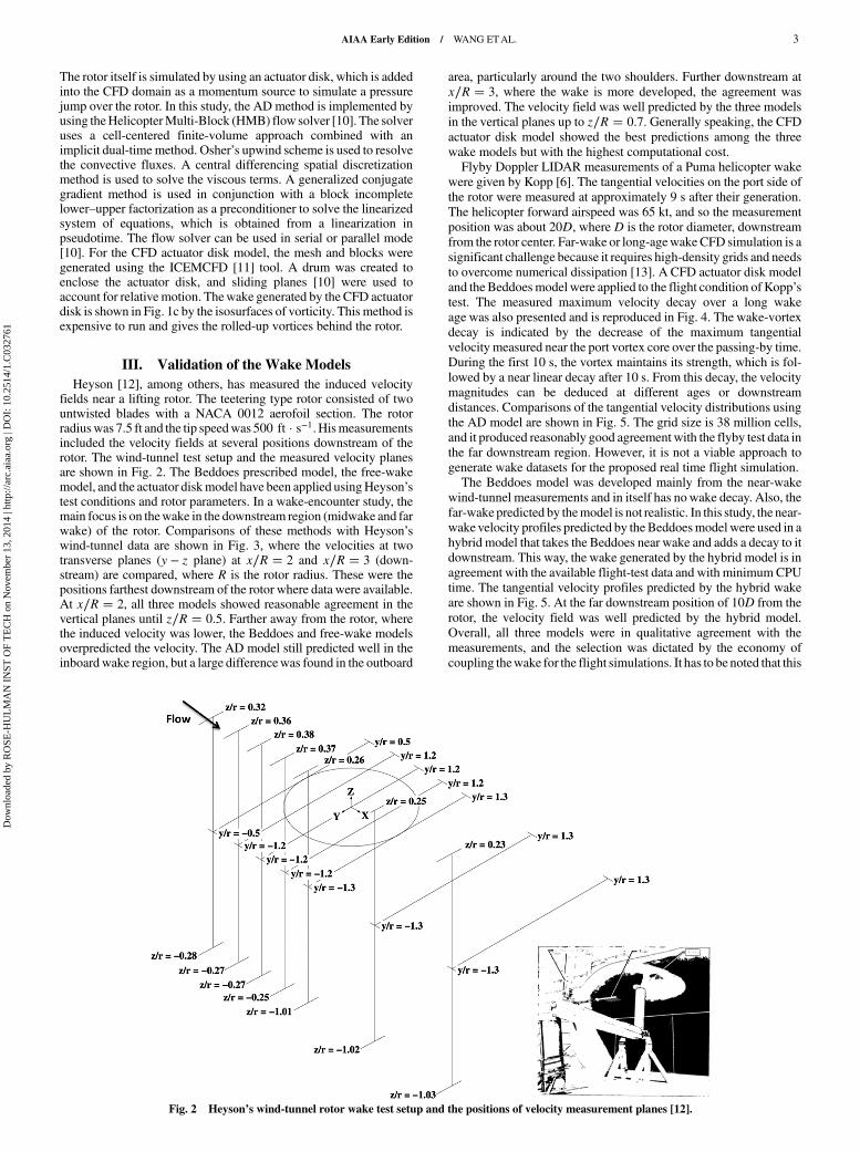
Heyson [12], among others, has measured the induced velocityfields near a lifting rotor. The teetering type rotor consisted of twountwisted blades with a NACA 0012 aerofoil section. The rotorradiuswas 7.5 ft and the tip speedwas 500 ft · s−1. Hismeasurementsincluded the velocity fields at several positions downstream of therotor. The wind-tunnel test setup and the measured velocity planesare shown in Fig. 2. The Beddoes prescribed model, the free-wakemodel, and the actuator diskmodel have been applied usingHeyson’stest conditions and rotor parameters. In a wake-encounter study, themain focus is on thewake in the downstream region (midwake and farwake) of the rotor. Comparisons of these methods with Heyson’swind-tunnel data are shown in Fig. 3, where the velocities at twotransverse planes (y − z plane) at x∕R � 2 and x∕R � 3 (down-stream) are compared, where R is the rotor radius. These were thepositions farthest downstream of the rotor where data were available.At x∕R � 2, all three models showed reasonable agreement in thevertical planes until z∕R � 0.5. Farther away from the rotor, wherethe induced velocity was lower, the Beddoes and free-wake modelsoverpredicted the velocity. The AD model still predicted well in theinboardwake region, but a large differencewas found in the outboard
area, particularly around the two shoulders. Further downstream atx∕R � 3, where the wake is more developed, the agreement wasimproved. The velocity field was well predicted by the three modelsin the vertical planes up to z∕R � 0.7. Generally speaking, the CFDactuator disk model showed the best predictions among the threewake models but with the highest computational cost.Flyby Doppler LIDAR measurements of a Puma helicopter wake
were given by Kopp [6]. The tangential velocities on the port side ofthe rotor were measured at approximately 9 s after their generation.The helicopter forward airspeed was 65 kt, and so the measurementposition was about 20D, where D is the rotor diameter, downstreamfrom the rotor center. Far-wake or long-agewake CFD simulation is asignificant challenge because it requires high-density grids and needsto overcome numerical dissipation [13]. A CFD actuator disk modeland the Beddoesmodel were applied to the flight condition of Kopp’stest. The measured maximum velocity decay over a long wakeage was also presented and is reproduced in Fig. 4. The wake-vortexdecay is indicated by the decrease of the maximum tangentialvelocity measured near the port vortex core over the passing-by time.During the first 10 s, the vortex maintains its strength, which is fol-lowed by a near linear decay after 10 s. From this decay, the velocitymagnitudes can be deduced at different ages or downstreamdistances. Comparisons of the tangential velocity distributions usingthe AD model are shown in Fig. 5. The grid size is 38 million cells,and it produced reasonably good agreement with the flyby test data inthe far downstream region. However, it is not a viable approach togenerate wake datasets for the proposed real time flight simulation.The Beddoes model was developed mainly from the near-wake
wind-tunnel measurements and in itself has nowake decay. Also, thefar-wake predicted by themodel is not realistic. In this study, the near-wake velocity profiles predicted by theBeddoesmodel were used in ahybrid model that takes the Beddoes near wake and adds a decay to itdownstream. This way, the wake generated by the hybrid model is inagreement with the available flight-test data and with minimumCPUtime. The tangential velocity profiles predicted by the hybrid wakeare shown in Fig. 5. At the far downstream position of 10D from therotor, the velocity field was well predicted by the hybrid model.Overall, all three models were in qualitative agreement with themeasurements, and the selection was dictated by the economy ofcoupling thewake for the flight simulations. It has to be noted that this
Fig. 2 Heyson’s wind-tunnel rotor wake test setup and the positions of velocity measurement planes [12].
AIAA Early Edition / WANG ETAL. 3
Dow
nloa
ded
by R
OSE
-HU
LM
AN
IN
ST O
F T
EC
H o
n N
ovem
ber
13, 2
014
| http
://ar
c.ai
aa.o
rg |
DO
I: 1
0.25
14/1
.C03
2761

was not an attempt to resolve all the details of the wake but only anattempt to add to the simulation the overall shape of thewakevelocity.The free-wake model was also used to simulate the far-field wake
of the aforementioned Puma helicopter tests. The results shown inFig. 5 are also in good agreement with the flyby test data. But themodel is not as effective as the hybrid model for the generation of the
far wake. Because the current study was focused on the wake of ahovering or hover-taxiing helicopter close to ground, it was con-sidered appropriate to compare the free-wake model against anyflight tests conducted near ground. Matayoshi et al. [14] presentedsome wake velocity measurements of a helicopter hovering close toground. In their flight tests, theMuPAL-ϵ helicopter hovered over the
y/R
V/V
0
-1.5 -1 -0.5 0 0.5 1 1.5y/R
-1.5 -1 -0.5 0 0.5 1 1.5
y/R-1.5 -1 -0.5 0 0.5 1 1.5
y/R-1.5 -1 -0.5 0 0.5 1 1.5
y/R-1.5 -1 -0.5 0 0.5 1 1.5
y/R-1.5 -1 -0.5 0 0.5 1 1.5
y/R-1.5 -1 -0.5 0 0.5 1 1.5
y/R-1.5 -1 -0.5 0 0.5 1 1.5
y/R-1.5 -1 -0.5 0 0.5 1 1.5
y/R-1.5 -1 -0.5 0 0.5 1 1.5
y/R-1.5 -1 -0.5 0 0.5 1 1.5
y/R-1.5 -1 -0.5 0 0.5 1 1.5
-1
-0.5
0
0.5
1
1.5
2 z/R= 0.18
V/V
0
-2
0
2
z/R= -0.16
V/V
0
-2
0
2
z/R= -0.36V
/V0
-2
-1.5
-1
-0.5
0
0.5
1
1.5
2
2.5
3z/R= -0.56
V/V
0
-1.5
-1
-0.5
0
0.5
1
1.5
2
2.5
3z/R= -0.76
V/V
0
-1
-0.5
0
0.5
1
1.5
2
2.5
3z/R= -1.02
Comparison with Heyson experiments Dot : Heyson ExpSolid_line : Actuator Disk
Dash_line : Free WakeDash_dot_line : Beddoesx/R= 2.0
V/V
0
-2
0
2
z/R= -0.10V
/V0
-2
0
2
4 z/R= -0.30
V/V
0
-2
-1.5
-1
-0.5
0
0.5
1
1.5
2
2.5z/R= -0.50
V/V
0
-2
-1.5
-1
-0.5
0
0.5
1
1.5
2
2.5z/R= -0.70
V/V
0
-1.5
-1
-0.5
0
0.5
1
1.5
2
2.5
z/R= -1.03
V/V
0
-1
-0.5
0
0.5
1
1.5
2
2.5 z/R= 0.10
Comparison with Heyson experimentsx/R= 3.0
Dot : Heyson Exp Solid_line : Actuator Disk
Dash_line : Free WakeDash_dot_line : Beddoes
a) x/R=2.0
b) x/R=3.0
Fig. 3 Comparison of three wake models against Heyson’s experiments [12] at a) x∕R � 2, and b) x∕R � 3 planes. Ct � 0.0064 and μ � 0.095.
4 AIAA Early Edition / WANG ETAL.
Dow
nloa
ded
by R
OSE
-HU
LM
AN
IN
ST O
F T
EC
H o
n N
ovem
ber
13, 2
014
| http
://ar
c.ai
aa.o
rg |
DO
I: 1
0.25
14/1
.C03
2761

anemometers at a height of 60–80 ft (Fig. 6), and the wake velocitieswere measured using a MELCO LIDAR [14] and ultrasonicanemometers. The free wake was applied to the MuPAL-ϵ helicopterusing the same parameters as those in the flight test. The comparisonof wake velocities generated by the free-wake model and measuredby LIDAR and anemometers are shown in Fig. 6. Notice that theLIDAR measurements were spatially averaged over a range binlength of 30 m [14], and the existence of a difference of peak andtrough velocities indicates that there might be a nature wind duringthe measurements, which biased the velocity field. After taking thesefactors into consideration, the free-wake model results were con-sidered to be in reasonable agreementwith those from the LIDARandanemometer measurements. Again, the objective here was to havecorrect magnitude of disturbance for the flight simulation.
IV. Induced Velocity Flowfield
The free-wake model was selected to generate the wake data forthe wake-encounter simulation after balancing the accuracy andcomputational cost of the three wake models. A Dauphin helicopterconfiguration was used in the wake-encounter simulation because it
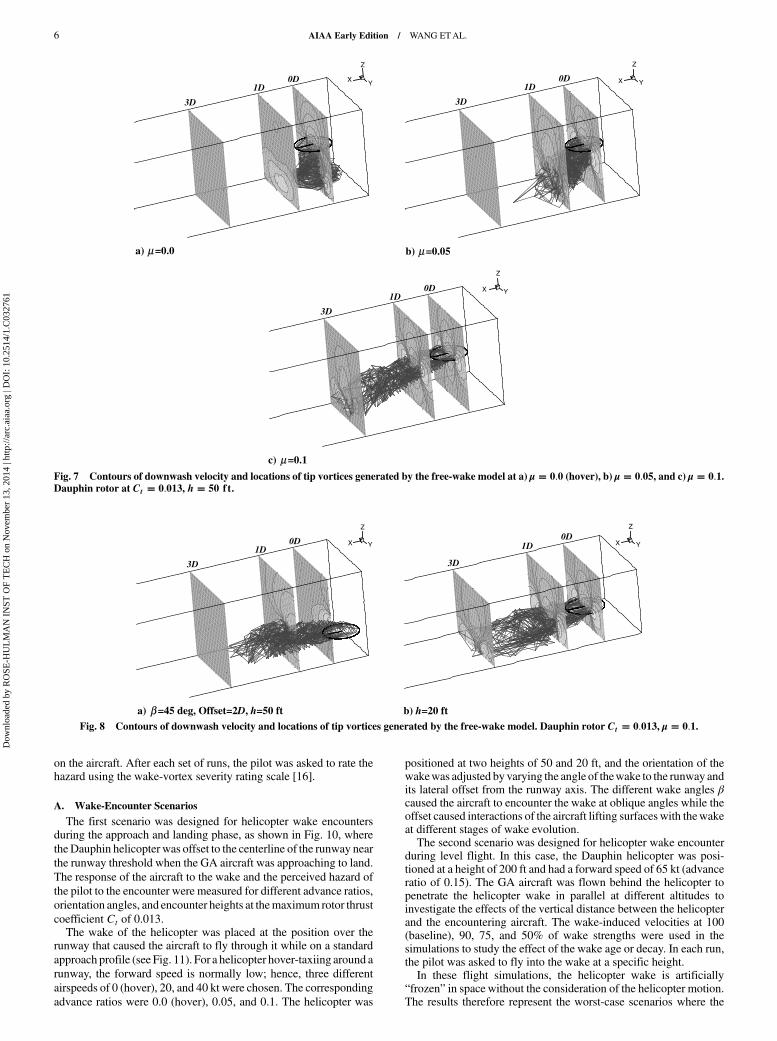
is considered as a light helicopter [1,2]. The wake-induced velocityvectors were calculated from the Biot–Savart law after the wake-vortex elements were determined from the free-wake model. Therotor hub was set at the origin (0, 0, 0) of the coordinate system alonga runway centerline over the runway threshold. The induced velocityfield covers a box of x � −20 to 320 ft (about eight rotor diameters),y � −50 to 50 ft, and z � −50 to 30 ft. The induced velocity field atdifferent advance ratios is shown in Fig. 7, where the wake geometryand three planes of velocity vectors and downwash contours at 0 (therotor hub center), 1D, and 3D downstream are displayed.The oblique wake encounter is shown in Fig. 8, where the orien-
tation angle is set to 45 deg, and the helicopter rotor hub is also offsettwo rotor diameters from the runway centerline. The wake-inducedvelocity field of the Dauphin helicopter at a lower height h of 20 ft isalso shown in Fig. 8. In this case, the influence of the ground effectwas more pronounced.The hybrid wake model, with the measured wake decay, was also
applied to the Dauphin helicopter rotor to generate the far-wakeflowfields. The induced-flow flowfields and the wake geometry areshown in Fig. 9 for the baselinewake (no decay) and for thewakewitha 50% decay.
V. Wake-Encounter Flight Simulation
The piloted wake-encounter flight simulations were carried out inthe HELIFLIGHT simulator [15] at the University of Liverpool bytwo test pilots and two student pilots. Thewake-encountering aircraftis a general aviation (GA) training aircraft configured to be similar toa Grob Tutor aircraft. During the simulation, the rolling/pitching/yawing moments, aircraft altitude change, velocities, and accel-erations during an encounter were recorded, together with the pilot’scontrol inputs, to capture a complete description of the encounter.These data provided a quantitative measure of the effect of the wake
Time (s)
Vm
ax (
ms-1
)
0 5 10 15 20 25 30 35 400
5
10
15
65 kt70 ktDeduced
Fig. 4 Measured velocity versus vortex age [6]. Puma helicopter at
speeds of 65 and 70 kt. The vertical dashed line indicates where theinduced velocity profile is available for comparision.
Z (m)
V (
ms-1
)
-10 0 10-10
-5
0
5
10
FlyBy-testAD_10DFreewake_10DHybrid_10D
Fig. 5 Velocity profiles predicted by the CFD actuator disk, the free-wake model, and the hybrid wake model. Puma helicopter at a speed of65 kt.
a) Downwash velocity measurement settings of a hovering MuPAL- helicopter [14]
Horizontal distance (m)
Vel
oci
ty (
ms-1
)
-60 -40 -20 0 20 40 60-15
-10
-5
0
5
10
15Free-wakeLIDARAnemometer
b) Comparison of wake velocities
Fig. 6 Representations of a) downwash velocity measurements andb) comparison of velocitieswith free-wakemodel. Four-bladedMuPAL-ϵhelicopter with a mass of 4500 kg, hovering at 60–80 ft above ground.
AIAA Early Edition / WANG ETAL. 5
Dow
nloa
ded
by R
OSE
-HU
LM
AN
IN
ST O
F T
EC
H o
n N
ovem
ber
13, 2
014
| http
://ar
c.ai
aa.o
rg |
DO
I: 1
0.25
14/1
.C03
2761
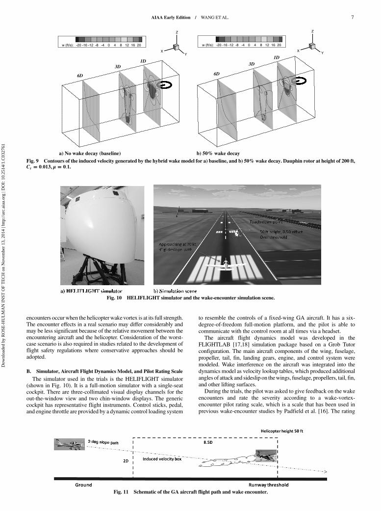
on the aircraft. After each set of runs, the pilot was asked to rate thehazard using the wake-vortex severity rating scale [16].
A. Wake-Encounter Scenarios
The first scenario was designed for helicopter wake encountersduring the approach and landing phase, as shown in Fig. 10, wheretheDauphin helicopter was offset to the centerline of the runway nearthe runway threshold when the GA aircraft was approaching to land.
The response of the aircraft to the wake and the perceived hazard ofthe pilot to the encounter were measured for different advance ratios,orientation angles, and encounter heights at themaximum rotor thrustcoefficient Ct of 0.013.The wake of the helicopter was placed at the position over the
runway that caused the aircraft to fly through it while on a standardapproach profile (see Fig. 11). For a helicopter hover-taxiing around arunway, the forward speed is normally low; hence, three different
airspeeds of 0 (hover), 20, and 40 kt were chosen. The correspondingadvance ratios were 0.0 (hover), 0.05, and 0.1. The helicopter was
positioned at two heights of 50 and 20 ft, and the orientation of thewakewas adjusted by varying the angle of thewake to the runway andits lateral offset from the runway axis. The different wake angles βcaused the aircraft to encounter the wake at oblique angles while theoffset caused interactions of the aircraft lifting surfaces with thewakeat different stages of wake evolution.The second scenario was designed for helicopter wake encounter
during level flight. In this case, the Dauphin helicopter was posi-tioned at a height of 200 ft and had a forward speed of 65 kt (advanceratio of 0.15). The GA aircraft was flown behind the helicopter topenetrate the helicopter wake in parallel at different altitudes toinvestigate the effects of the vertical distance between the helicopterand the encountering aircraft. The wake-induced velocities at 100(baseline), 90, 75, and 50% of wake strengths were used in thesimulations to study the effect of the wake age or decay. In each run,the pilot was asked to fly into the wake at a specific height.In these flight simulations, the helicopter wake is artificially
“frozen” in space without the consideration of the helicopter motion.The results therefore represent the worst-case scenarios where the
X Y
Z
0D1D
3D
a) μ =0.0 b) μ =0.05
c) μ =0.1
X Y
Z
0D1D
3D
X Y
Z
0D1D
3D
Fig. 7 Contours of downwash velocity and locations of tip vortices generated by the free-wake model at a) μ � 0.0 (hover), b) μ � 0.05, and c) μ � 0.1.Dauphin rotor at Ct � 0.013, h � 50 ft.
X Y
Z
0D1D
3D
a) β =45 deg, Offset=2D, h=50 ft
X Y
Z
0D1D
3D
b) h=20 ft
Fig. 8 Contours of downwash velocity and locations of tip vortices generated by the free-wake model. Dauphin rotor Ct � 0.013, μ � 0.1.
6 AIAA Early Edition / WANG ETAL.
Dow
nloa
ded
by R
OSE
-HU
LM
AN
IN
ST O
F T
EC
H o
n N
ovem
ber
13, 2
014
| http
://ar
c.ai
aa.o
rg |
DO
I: 1
0.25
14/1
.C03
2761
encounters occurwhen the helicopterwakevortex is at its full strength.The encounter effects in a real scenario may differ considerably andmay be less significant because of the relative movement between theencountering aircraft and the helicopter. Consideration of the worst-case scenario is also required in studies related to the development offlight safety regulations where conservative approaches should beadopted.
B. Simulator, Aircraft Flight Dynamics Model, and Pilot Rating Scale
The simulator used in the trials is the HELIFLIGHT simulator(shown in Fig. 10). It is a full-motion simulator with a single-seatcockpit. There are three-collimated visual display channels for theout-the-window view and two chin-window displays. The genericcockpit has representative flight instruments. Control sticks, pedal,and engine throttle are provided by a dynamic control loading system
to resemble the controls of a fixed-wing GA aircraft. It has a six-degree-of-freedom full-motion platform, and the pilot is able tocommunicate with the control room at all times via a headset.The aircraft flight dynamics model was developed in the
FLIGHTLAB [17,18] simulation package based on a Grob Tutorconfiguration. The main aircraft components of the wing, fuselage,propeller, tail, fin, landing gears, engine, and control system weremodeled. Wake interference on the aircraft was integrated into thedynamics model as velocity lookup tables, which produced additionalangles of attack and sideslip on thewings, fuselage, propellers, tail, fin,and other lifting surfaces.During the trials, the pilot was asked to give feedback on the wake
encounters and rate the severity according to a wake-vortex-encounter pilot rating scale, which is a scale that has been used inprevious wake-encounter studies by Padfield et al. [16]. The rating
XY
Z
w (ft/s): -20 -16 -12 -8 -4 0 4 8 12 16 20
1D3D
6D
a) No wake decay (baseline)
XY
Z
w (ft/s): -20 -16 -12 -8 -4 0 4 8 12 16 20
1D
6D
3D
b) 50% wake decay
Fig. 9 Contours of the induced velocity generated by the hybrid wake model for a) baseline, and b) 50%wake decay. Dauphin rotor at height of 200 ft,Ct � 0.013, μ � 0.1.
Fig. 10 HELIFLIGHT simulator and the wake-encounter simulation scene.
Fig. 11 Schematic of the GA aircraft flight path and wake encounter.
AIAA Early Edition / WANG ETAL. 7
Dow
nloa
ded
by R
OSE
-HU
LM
AN
IN
ST O
F T
EC
H o
n N
ovem
ber
13, 2
014
| http
://ar
c.ai
aa.o
rg |
DO
I: 1
0.25
14/1
.C03
2761

scale is shown in Fig. 12. It is a simple decision tree that enables thepilots to provide a subjective assessment of the effect of the wakeencounter and their ability to recover.
C. Test Procedure
For each test condition, the pilots were asked to fly the GA aircraftalong a 3 deg glide slope path, aiming to land the aircraft at a specifiedtouchdown point for the landing scenario, or to fly at a specific
altitude for the level-flight scenario. The wake was placed at specificpositions according to the test matrix. The pilot was not informedwhether the wake was present or not. In each simulation sortie, thepilot was asked to give wake-encounter severity ratings if the wakewas detected. In addition to the rating, other parameters related to theaircraft dynamics, positions, and pilot control activities were alsorecorded for further analysis. Typically, several runs of the same testcondition were carried out to obtain consistent results.
Fig. 12 Pilot wake-encounter severity rating scale [16].
8 AIAA Early Edition / WANG ETAL.
Dow
nloa
ded
by R
OSE
-HU
LM
AN
IN
ST O
F T
EC
H o
n N
ovem
ber
13, 2
014
| http
://ar
c.ai
aa.o
rg |
DO
I: 1
0.25
14/1
.C03
2761

VI. Simulation Results and Discussion
A. Helicopter Wake Encounter During a Landing
1. Vortex Upset Hazard
The helicopter wake-vortex-induced disturbances were probedby theGA light aircraft in the simulation to obtain a direct assessmentof wake-vortex hazard as a function of distance behind the wake-generating helicopter. In addition to the pilot’s awarded wake-encounter severity rating and comments, the aircraft dynamic responseparameters can be used to assess the wake-vortex upset hazard.The criteria for test pilot assessments are dependent on the manner
in which the assessment evolved [5]. For fixed-wing aircraftencounters, generalized criteria need to be used during an approach todetermine the limits of upsets (roll, pitch, yaw, and any acceleration)that would permit the continuation of the approach rather than a go-around. The amount of control used and the most severe aircraftexcursions that the pilots would tolerate need to be considered [5].For a more definitive criterion, a rule of thumb has evolved thatsuggested that the maximum acceptable bank angle at publishedminimums would be that obtained by dividing 1200 by thewingspanin feet [5]. For a Boeing 747, it equates to 6 deg of bank, whereas forsmaller aircraft like Grob Tutor (10 mwingspan), it is approximately35 deg. Normally, the hazardous roll angle limit was rounded off to30 deg. The hazard distance was defined by Teager et al. [5] as thedistance at which a nominal 30 deg bank upset is caused.In a helicopterwake encounter, the perceived severity of the hazard
caused by the wake vortex on the encountering aircraft depends onthe height and the speed of the helicopter and the vortex age, which isreflected in terms of the distance of the encounter behind the wake-generating helicopter.The time-history plots of the aircraft responses and pilot control
activity in a typical wake-encounter case are shown in Fig. 13. Theleft-hand figures show the dynamic responses of aircraft attitude ofroll, pitch, and yaw angles as well as rates and accelerations. Thepilot’s control activities of the lateral and longitudinal sticks aswell asthe pedal, the altitude of the aircraft, and the body accelerations in x,y, and z body axes are plotted in the right-hand column of the figures.The aircraft encounters the wake at approximately 47 s. The pilotgave this wake encounter an F rating, which represents a hazardousencounter for a landing scenario. The pilot commented that if thewake encounter had happened at a higher altitude, then the ratingwould have been a D.
In the current landing simulations, the aircraft bank angle did notexceed 30 deg even for the most severely rated upset encounter.However, the test pilot gave an F rating for some of the encounters,which means that, in his opinion, the safety of flight was com-promised and the hazard is intolerable. The reason that the pilot gavesuch a high rating is that although the aircraft upset due to the vortexencounter is relatively small, the proximity of the aircraft to theground during the landing phase means that there is little room tomanoeuvre and recover the aircraft from the upset. The 30 deg bankangle criterion might not be as well suited to wake encounters duringlanding.Another criterion for the wake encounter is the vortex upset de-
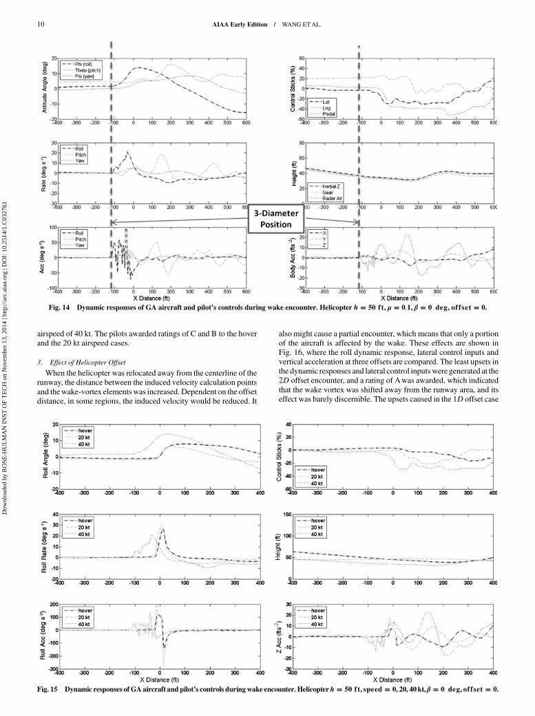
tectability distance at which the impact of the helicopter’s wakevortex can be detected by the approaching aircraft. The data of theprevious test case are replotted in Fig. 14, where the horizontaldistance X between the aircraft and the helicopter was used. Theposition of three times the rotor diameter was also indicated on theplots. The helicopter was positioned at the runway threshold (X � 0)and at a height of 50 ft. TheGAaircraft approached landing on a 3 degflight path. The roll acceleration and vertical Z body accelerationstarted to show abrupt changes at a distance of about 120 ft (3D)from the helicopter position. At a distance of about 80 ft (2D), theaccelerations in pitch appeared. The peak of roll attitude rate was21 deg · s−1, and peak roll angle was about 14 deg. A similar pitchrate appeared later, and the maximum pitch angle was 16 deg. Asmaller yawacceleration, yaw rate, and yaw anglewere also observedin the plots. The pilot applied lateral control to compensate the rolldisturbance, and later longitudinal and pedal controls were alsoapplied.
2. Helicopter Advance Ratio
A higher advance ratio causes a smaller wake skew angle, and thewake vortex extends further downstream. Figure 15 shows the rolldynamic response, vertical acceleration, and lateral control inputs athelicopter airspeeds of 0 (hover), 20, and 40 kt. The roll accelerationand rate plots indicated that the wake-encounter detectability dis-tances were at about 120 ft (3D), 70 ft (1.8D), and 30 ft (0.8D) for thethree conditions. Larger roll accelerations and rates were produced inthe lower-airspeed cases as the encounter occurred closer to thehelicopter. However, the largest roll angle, lateral control displace-ment, and vertical body accelerations were generated at the highest
Fig. 13 Dynamic responses of GA aircraft and pilot’s controls during wake encounter. Helicopter h � 50 ft, μ � 0.1, β � 0 deg, offset � 0.
AIAA Early Edition / WANG ETAL. 9
Dow
nloa
ded
by R
OSE
-HU
LM
AN
IN
ST O
F T
EC
H o
n N
ovem
ber
13, 2
014
| http
://ar
c.ai
aa.o
rg |
DO
I: 1
0.25
14/1
.C03
2761
airspeed of 40 kt. The pilots awarded ratings of C and B to the hoverand the 20 kt airspeed cases.
3. Effect of Helicopter Offset
When the helicopter was relocated away from the centerline of therunway, the distance between the induced velocity calculation pointsand thewake-vortex elements was increased. Dependent on the offsetdistance, in some regions, the induced velocity would be reduced. It
also might cause a partial encounter, which means that only a portionof the aircraft is affected by the wake. These effects are shown inFig. 16, where the roll dynamic response, lateral control inputs andvertical acceleration at three offsets are compared. The least upsets inthe dynamic responses and lateral control inputswere generated at the2D offset encounter, and a rating of Awas awarded, which indicatedthat the wake vortex was shifted away from the runway area, and itseffect was barely discernible. The upsets caused in the 1D offset case
Fig. 14 Dynamic responses of GA aircraft and pilot’s controls during wake encounter. Helicopter h � 50 ft, μ � 0.1, β � 0 deg, offset � 0.
Fig. 15 Dynamic responses of GAaircraft and pilot’s controls duringwake encounter. Helicopterh � 50 ft, speed � 0, 20, 40 kt, β � 0 deg, offset � 0.
10 AIAA Early Edition / WANG ETAL.
Dow
nloa
ded
by R
OSE
-HU
LM
AN
IN
ST O
F T
EC
H o
n N
ovem
ber
13, 2
014
| http
://ar
c.ai
aa.o
rg |
DO
I: 1
0.25
14/1
.C03
2761

are still large because of the partial encounter and resulted in a Crating. The changes of the signs in the roll angle, the roll rate, andacceleration as well as the lateral control indicated that the encounterwas different from that of the no-offset case.
4. Wake-Encountering Angles
The wake-encounter angle changes the orientation between thewake vortex to the fixed induced velocity field. It is anticipated thatthe resulting wake-induced velocity distribution would be alteredwhen compared with the parallel (zero angle) encounter case. Theeffect of the encounter angle is shown inFig. 17,where the roll dynam-ic responses, lateral control, and vertical acceleration are compared.
The wakes were positioned at a offset of 1D from the runway cen-terline. The oblique encounters (45 deg) caused the least upsets in theroll angle and the lateral control, and a B rating was awarded. Thisis partly because of the fact that the wake vortex was skewed awayfrom the centerline of the induced velocity field, which increasedthe distance between the vortex elements and the induced velocitycalculation points. This larger distance reduced the induced velocityand hence generated less of an upset. In the crossing encounter(90 deg), the shortest detectability distance about 30 ft (0.75D) wasfound.The detectability distanceswere 120 ft (3D) and 90 ft (2.3D) forthe parallel and the oblique encounters, and a C rating was awardedfor both.
Fig. 16 Dynamic responses of GA aircraft and pilot’s controls during wake encounter. Helicopter h � 50 ft, μ � 0.1, β � 0 deg, offset � 0, 1D, 2D.
Fig. 17 Dynamic responses of GA aircraft and pilot’s controls during wake encounter. Helicopter h � 50 ft, μ � 0.1, β � 0, 45, 90 deg; offset � 1D.
AIAA Early Edition / WANG ETAL. 11
Dow
nloa
ded
by R
OSE
-HU
LM
AN
IN
ST O
F T
EC
H o
n N
ovem
ber
13, 2
014
| http
://ar
c.ai
aa.o
rg |
DO
I: 1
0.25
14/1
.C03
2761
5. Helicopter Altitude
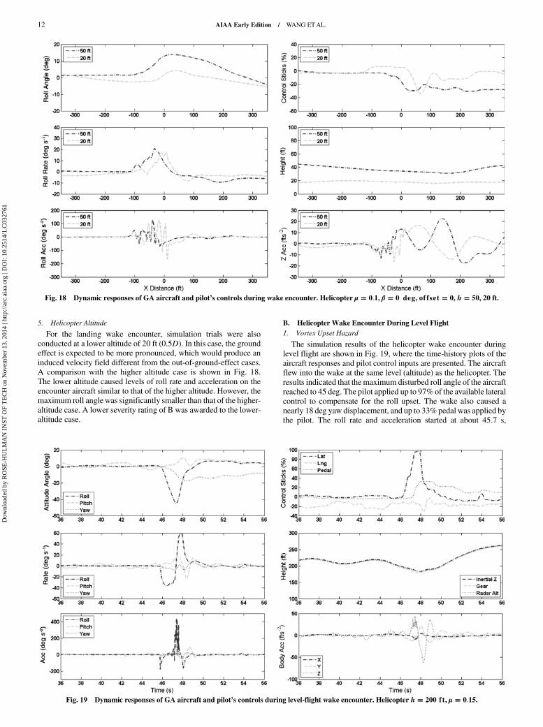
For the landing wake encounter, simulation trials were alsoconducted at a lower altitude of 20 ft (0.5D). In this case, the groundeffect is expected to be more pronounced, which would produce aninduced velocity field different from the out-of-ground-effect cases.A comparison with the higher altitude case is shown in Fig. 18.The lower altitude caused levels of roll rate and acceleration on theencounter aircraft similar to that of the higher altitude. However, themaximum roll anglewas significantly smaller than that of the higher-altitude case. A lower severity rating of B was awarded to the lower-altitude case.
B. Helicopter Wake Encounter During Level Flight
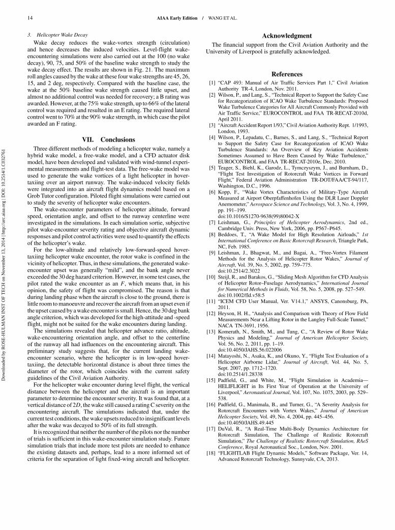
1. Vortex Upset Hazard
The simulation results of the helicopter wake encounter duringlevel flight are shown in Fig. 19, where the time-history plots of theaircraft responses and pilot control inputs are presented. The aircraftflew into the wake at the same level (altitude) as the helicopter. Theresults indicated that the maximum disturbed roll angle of the aircraftreached to 45 deg. The pilot applied up to 97% of the available lateralcontrol to compensate for the roll upset. The wake also caused anearly 18 deg yaw displacement, and up to 33% pedal was applied bythe pilot. The roll rate and acceleration started at about 45.7 s,
Fig. 18 Dynamic responses of GA aircraft and pilot’s controls during wake encounter. Helicopter μ � 0.1, β � 0 deg, offset � 0, h � 50, 20 ft.
Fig. 19 Dynamic responses of GA aircraft and pilot’s controls during level-flight wake encounter. Helicopter h � 200 ft, μ � 0.15.
12 AIAA Early Edition / WANG ETAL.
Dow
nloa
ded
by R
OSE
-HU
LM
AN
IN
ST O
F T
EC
H o
n N
ovem
ber
13, 2
014
| http
://ar
c.ai
aa.o
rg |
DO
I: 1
0.25
14/1
.C03
2761

corresponding to a distance of about 300 ft (7.5D) from the rotorcenter. The pilot gave this wake-encounter severity a G rating,meaning that the excursion of the aircraft states was sufficiently highthat safe recovery could not be assured.
2. Helicopter Height and Aircraft Altitude
In the level-flight simulation, the pilots were asked to fly the GAaircraft to penetrate the helicopter wake at different altitudes toinvestigate the effects of the vertical distance between the helicopterand the encountering aircraft. The wake is skewed when thehelicopter is flying at a forward speed of 65 kt (μ � 0.15). Thewake-
induced velocity field is highly dependent on not only the horizontaldistance but also the vertical distance. The results are shown inFig. 20. In the baseline case (altitude of 200 ft), the GA aircraft wasflying at the same height as the Dauphin helicopter, and the wakecaused the largest disturbances in the roll axis. The lower the altitudeof the aircraft was, the less roll upsets were produced. The controlinputs were also reduced at the lower altitude. At an altitude of 120 ft,the vertical distance between the helicopter and the GA aircraft wasabout 2D, the wake caused a maximum roll angle of 9 deg, and thepilot had to apply up to 46% of the lateral control to recover theattitude. In this case, the pilot awarded a C severity rating.
Fig. 20 Dynamic responses of GA aircraft and pilot’s controls during level-flight wake encounter. Helicopter h � 200 ft, μ � 0.15, GA aircraftaltitude � 200, 180, 150, 120 ft.
Fig. 21 Dynamic responses of GA aircraft and pilot’s controls during level-flight wake encounter. Helicopter h � 200 ft, μ � 0.15, wake decay of 100,90, 75, and 50%.
AIAA Early Edition / WANG ETAL. 13
Dow
nloa
ded
by R
OSE
-HU
LM
AN
IN
ST O
F T
EC
H o
n N
ovem
ber
13, 2
014
| http
://ar
c.ai
aa.o
rg |
DO
I: 1
0.25
14/1
.C03
2761
3. Helicopter Wake Decay
Wake decay reduces the wake-vortex strength (circulation)and hence decreases the induced velocities. Level-flight wake-encountering simulations were also carried out at the 100 (no wakedecay), 90, 75, and 50% of the baseline wake strength to study thewake decay effect. The results are shown in Fig. 21. The maximumroll angles caused by thewake at these fourwake strengths are 45, 26,15, and 2 deg, respectively. Compared with the baseline case, thewake at the 50% baseline wake strength caused little upset, andalmost no additional control was needed for recovery; a B rating wasawarded. However, at the 75%wake strength, up to 66%of the lateralcontrol was required and resulted in an E rating. The required lateralcontrol went to 70% at the 90%wake strength, in which case the pilotawarded an F rating.
VII. Conclusions
Three different methods of modeling a helicopter wake, namely ahybrid wake model, a free-wake model, and a CFD actuator diskmodel, have been developed and validated with wind-tunnel experi-mental measurements and flight-test data. The free-wake model wasused to generate the wake vortices of a light helicopter in hover-taxiing over an airport runway. The wake-induced velocity fieldswere integrated into an aircraft flight dynamics model based on aGrob Tutor configuration. Piloted flight simulations were carried outto study the severity of helicopter wake encounters.The wake-encounter parameters of helicopter altitude, forward
speed, orientation angle, and offset to the runway centerline wereinvestigated in the simulations. In each simulation sortie, subjectivepilot wake-encounter severity rating and objective aircraft dynamicresponses and pilot control activities were used to quantify the effectsof the helicopter’s wake.For the low-altitude and relatively low-forward-speed hover-
taxiing helicopter wake encounter, the rotor wake is confined in thevicinity of helicopter. Thus, in these simulations, the generatedwake-encounter upset was generally “mild”, and the bank angle neverexceeded the 30 deghazard criterion.However, in some test cases, thepilot rated the wake encounter as an F, which means that, in hisopinion, the safety of flight was compromised. The reason is thatduring landing phase when the aircraft is close to the ground, there islittle room tomanoeuvre and recover the aircraft from an upset even ifthe upset caused by awake encounter is small.Hence, the 30 deg bankangle criterion, which was developed for the high-attitude and -speedflight, might not be suited for the wake encounters during landing.The simulations revealed that helicopter advance ratio, altitude,
wake-encountering orientation angle, and offset to the centerlineof the runway all had influences on the encountering aircraft. Thispreliminary study suggests that, for the current landing wake-encounter scenario, where the helicopter is in low-speed hover-taxiing, the detectable horizontal distance is about three times thediameter of the rotor, which coincides with the current safetyguidelines of the Civil Aviation Authority.For the helicopter wake encounter during level flight, the vertical
distance between the helicopter and the aircraft is an importantparameter to determine the encounter severity. It was found that, at avertical distance of 2D, thewake still caused a ratingC severity on theencountering aircraft. The simulations indicated that, under thecurrent test conditions, thewake upsets reduced to insignificant levelsafter the wake was decayed to 50% of its full strength.It is recognized that neither the number of the pilots nor the number
of trials is sufficient in this wake-encounter simulation study. Futuresimulation trials that include more test pilots are needed to enhancethe existing datasets and, perhaps, lead to a more informed set ofcriteria for the separation of light fixed-wing aircraft and helicopter.
Acknowledgment
The financial support from the Civil Aviation Authority and theUniversity of Liverpool is gratefully acknowledged.
References
[1] “CAP 493: Manual of Air Traffic Services Part 1,” Civil AviationAuthority TR-4, London, Nov. 2011.
[2] Wilson, P., and Lang, S., “Technical Report to Support the Safety Casefor Recategorization of ICAO Wake Turbulence Standards: ProposedWake Turbulence Categories for All Aircraft Commonly Provided withAir Traffic Service,” EUROCONTROL and FAA TR-RECAT-2010d,April 2011.
[3] “Aircraft Accident Report 1/93,”Civil AviationAuthorityRept. 1/1993,London, 1993.
[4] Wilson, P., Lepadatu, C., Barnes, S., and Lang, S., “Technical Reportto Support the Safety Case for Recategorization of ICAO WakeTurbulence Standards: An Overview of Key Aviation AccidentsSometimes Assumed to Have Been Caused by Wake Turbulence,”EUROCONTROL and FAA TR-RECAT-2010e, Dec. 2010.
[5] Teager, S., Biehl, K., Garodz, L., Tymczyszym, J., and Burnham, D.,“Flight Test Investigation of Rotorcraft Wake Vortices in ForwardFlight,” Federal Aviation Administration TR-DOT/FAA/CT-94/117,Washington, D.C., 1996.
[6] Kopp, F., “Wake Vortex Characteristics of Military-Type AircraftMeasured at Airport Oberpfaffenhofen Using the DLR Laser DopplerAnemometer,” Aerospace Science and Technology, Vol. 3, No. 4, 1999,pp. 191–199.doi:10.1016/S1270-9638(99)80042-X
[7] Leishman, G., Principles of Helicopter Aerodynamics, 2nd ed.,Cambridge Univ. Press, New York, 2006, pp. P567–P645.
[8] Beddoes, T., “A Wake Model for High Resolution Airloads,” 1st
International Conference on Basic Rotorcraft Research, Triangle Park,NC, Feb. 1985.
[9] Leishman, J., Bhagwat, M., and Bagai, A., “Free-Vortex FilamentMethods for the Analysis of Helicopter Rotor Wakes,” Journal of
Aircraft, Vol. 39, No. 5, 2002, pp. 759–775.doi:10.2514/2.3022
[10] Steijl, R., and Barakos, G., “Sliding Mesh Algorithm for CFDAnalysisof Helicopter Rotor–Fuselage Aerodynamics,” International Journal
for Numerical Methods in Fluids, Vol. 58, No. 5, 2008, pp. 527–549.doi:10.1002/fld.v58:5
[11] “ICEM CFD User Manual, Ver. V14.1,” ANSYS, Canonsburg, PA,2011.
[12] Heyson, H. H., “Analysis and Comparison with Theory of Flow FieldMeasurements Near a Lifting Rotor in the Langley Full-Scale Tunnel,”NACA TN-3691, 1956.
[13] Komerath, N., Smith, M., and Tung, C., “A Review of Rotor WakePhysics and Modeling,” Journal of American Helicopter Society,Vol. 56, No. 2, 2011, pp. 1–19.doi:10.4050/JAHS.56.022006
[14] Matayoshi, N., Asaka, K., and Okuno, Y., “Flight Test Evaluation of aHelicopter Airborne Lidar,” Journal of Aircraft, Vol. 44, No. 5,Sept. 2007, pp. 1712–1720.doi:10.2514/1.28338
[15] Padfield, G., and White, M., “Flight Simulation in Academia—HELIFLIGHT in Its First Year of Operation at the University ofLiverpool,” Aeronautical Journal, Vol. 107, No. 1075, 2003, pp. 529–538.
[16] Padfield, G., Manimala, B., and Turner, G., “A Severity Analysis forRotorcraft Encounters with Vortex Wakes,” Journal of American
Helicopter Society, Vol. 49, No. 4, 2004, pp. 445–456.doi:10.4050/JAHS.49.445
[17] DuVal, R., “A Real-Time Multi-Body Dynamics Architecture forRotorcraft Simulation, The Challenge of Realistic RotorcraftSimulation,” The Challenge of Realistic Rotorcraft Simulation, RAeS
Conference, Royal Aeronautical Soc., London, Nov. 2001.[18] “FLIGHTLAB Flight Dynamic Models,” Software Package, Ver. 14,
Advanced Rotorcraft Technology, Sunnyvale, CA, 2013.
14 AIAA Early Edition / WANG ETAL.
Dow
nloa
ded
by R
OSE
-HU
LM
AN
IN
ST O
F T
EC
H o
n N
ovem
ber
13, 2
014
| http
://ar
c.ai
aa.o
rg |
DO
I: 1
0.25
14/1
.C03
2761