simulating iot frameworks and devices in the … iot frameworks and devices in the smart home john...
TRANSCRIPT

Simulating IoT Frameworks and Devices in the Smart Home
John Kalin
Thesis submitted to the faculty of the Virginia Polytechnic Institute and State University in partial fulfillment of the requirements for the degree
of
Master of Science In
Computer Engineering
Joseph G. Tront William O. Plymale Thomas L. Martin
August 10, 2017 Blacksburg, VA
Keywords: IoT, Simulation, Smart Home, Network, OpenHAB

Simulating IoT Frameworks and Devices in the smart home
John Kalin
ABSTRACT The rapid growth of the Internet of Things (IoT) has led to a situation where individual
manufacturers develop their own communication protocols and frameworks that are often
incompatible with other systems. Part of this is due to the use of incompatible communication
hardware, and part is due to the entrenched proprietary systems. This has created a heterogeneous
communication landscape, where it is difficult for devices to coordinate their efforts. To remedy
this, a number of IoT Frameworks have been proposed to provide a common interface between
IoT devices. There are many approaches to common frameworks, each with their strengths and
weaknesses, but there is no clear winner among them. This thesis presents a virtual network testbed
for implementing smart home IoT Frameworks. It consists of a simulated home network made up
of multiple Virtual Machines (VM), simulated smart home devices and an implementation of the
OpenHAB framework to integrate the devices. Simulated devices are designed to be network-
accurate representations of actual devices, a LIFX smart lightbulb was developed and an existing
Nest thermostat simulation was integrated. The demonstrated setup serves as a proof of concept
for the idea of a home network testbed. Such a testbed could allow for the development of new
IoT frameworks or the comparison of existing ones, and it could also serve as an education aid to
illustrate how smart home IoT devices communicate with one another.
Simulating IoT Frameworks and Devices in the smart home
John Kalin
GENERAL AUDIENCE ABSTRACT The rapid growth of the Internet of Things (IoT) has led to a situation where individual
manufacturers develop their own systems for communicating with devices, which don’t work with
other devices. A lot of this is due to devices using different technologies; for example, a Bluetooth
device trying to talk to a Wi-Fi device. This has created a situation where it is difficult for different
devices to communicate. To remedy this, a number of IoT Frameworks have been proposed to
provide a common language between IoT devices. There are many approaches to common
frameworks, each with their strengths and weaknesses, but there is no clear winner among them.
This thesis presents a simulation environment for smart home IoT Frameworks. It consists of a
simulated home network made up of multiple Virtual Machines (VM), simulated smart home
devices and an implementation of the OpenHAB framework to integrate the devices. Simulated
devices are designed to be accurate representations of actual devices, a LIFX smart lightbulb was
developed and an existing Nest thermostat simulation was integrated. The demonstrated setup
serves as a proof of concept for the idea of a home network testbed. Such a testbed could allow for
the development of new IoT frameworks or the comparison of existing ones, and it could also
serve as an education aid to illustrate how smart home IoT devices communicate with one another.

iv
Table of Contents
Table of Contents …………………………………………………………………………. iv List of Figures …………………………………………………………………………...... vi Chapter 1 Introduction …………………………………………………………………...... 1 1.1 Motivation and Goal ………………………..………………………………………... 2
Chapter 2 Background …………………………………………………………………….. 4 2.1 Communication Technology ………………………………………………………… 4 2.1.1 Bluetooth Wireless Technology ………………………………………………….. 4 2.1.2 IEEE 802.15.4 Standard-based Protocols ………………………………………… 7 2.1.2.1 ZigBee Personal Area Network Technology ………………………………….. 8 2.1.2.2 6LoWPAN Low Power IPv6 Technology …………………………………….. 10 2.1.3 Z-Wave Low Energy Technology ………………………………………………... 11 2.1.4 Wi-Fi and Ethernet Technology ………………………………………………….. 13 2.2 IoT Frameworks ……………………………………………………………………... 15 2.2.1 Proprietary Frameworks ………………………………………………………….. 16 2.2.1.1 Apple HomeKit ……………………………………………………………….. 17 2.2.1.2 Google Weave ………………………………………………………………… 18 2.2.2 Open-Source Frameworks ………………………………………………………... 19 2.2.2.1 Samsung SmartThings ………………………………………………………… 19 2.2.2.2 AllSeen Alliance AllJoyn ……………………………………………………... 21 2.2.2.3 Linux Foundation IoTivity ……………………………………………………. 22 2.2.2.4 OpenHAB ……………………………………………………………………... 23 2.2.2.5 Other Open-Source Frameworks ……………………………………………… 25 2.2.3 General Security and Privacy of Frameworks ……………………………………. 26 2.2.3.1 Varied Landscape of Devices …………………………………………………. 27 2.2.3.2 Tendency Towards Over-Privilege ……………………………………………. 27 2.2.3.3 Encryption of Communication ………………………………………………... 29 2.2.3.4 Privacy Concerns ……………………………………………………………… 29 2.2.4 General Support and Ease of Use of Frameworks ……………………………….. 30 2.3 IoT Simulation ……………………………………………………………………….. 31 2.3.1 Application Development ………………………………………………………… 31 2.3.2 Academic Simulations ……………………………………………………………. 33 Chapter 3 Experimental Methodology ……………………………………………………. 41 3.1 Proposed Approach ………………………………………………………………….. 41 3.2 Network Setup ……………………………………………………………………….. 42 3.3 LIFX Bulb …………………………………………………………………………… 46 3.3.1 LIFX LAN Protocol ……………………………………………………………… 47 3.3.2 Simulated LIFX Bulb …………………………………………………………….. 50 3.3.3 Packet Sniffing LIFX …………………………………………………………….. 53 3.4 Nest Thermostat ……………………………………………………………………… 55 3.4.1 Thread and Nest Weave Fabric …………………………………………………… 55 3.4.2 Nest Home Simulation ……………………………………………………………. 59 3.5 OpenHAB Framework ………………………………………………………………. 60 3.5.1 LIFX Setup in OpenHAB ………………………………………………………… 61 3.5.2 Nest Setup in OpenHAB …………………………………………………………. 64

v
3.5.3 Remote Access Setup …………………………………………………………….. 67 Chapter 4 Testing and Validation …………………………………………………………. 69 Chapter 5 Using Developed Tools ………………………………………………………… 72 5.1 Simulated Network Setup ……………………………………………………………. 72 5.2 LIFX Simulation Setup ………………………………………………………………. 75 5.3 Nest Home Simulator Setup …………………………………………………………. 76 5.4 OpenHAB Setup ……………………………………………………………………... 79 5.5 Simulating Additional Devices ………………………………………………………. 80 Chapter 6 Conclusion ……………………………………………………………………… 84 Chapter 7 Future Work ……………………………………………………………………. 86 References ………………………………………………………………………………… 87 Appendix A. Specified vs Actual LIFX Validity Table ………………………………….. 91 Appendix B. LIFX Protocols and Payloads ………………………………………………. 93 Appendix C. Capture of Undocumented LIFX Packets ………………………………….. 95 Appendix D. Capture of LIFX AllJoyn Packets ………………………………………….. 98 Appendix E. Sample Python Custom Packet Class ……………………………………….. 99

vi
List of Figures
Figure 1. Block diagram for a typical IoT configuration ……………………..…………… 1 Figure 2. Bluetooth Piconet topology ……………………………………………………... 5 Figure 3. Bluetooth Scatternet topology …………………………………………………... 6 Figure 4. ZigBee Network Topologies ……………………………………………………. 9 Figure 5. Z-Wave Protocol Stack …………………………………………………………. 13 Figure 6. Non-Integrated smart home Setup with Cloud Services ………………………. 15 Figure 7. SmartThings Container Hierarchy ………………………………………………. 21 Figure 8. Integrated smart home Setup with Cloud Services …………………………….. 26 Figure 9. Screenshot of Nest Home Simulator Interface ………………………………….. 32 Figure 10. Diagram of simulated HVAC System …………………………………………. 35 Figure 11. Diagram showing use of emulated IoT Gateway ……………………………… 37 Figure 12. Diagram showing QLM being used to merge data from various sources …….. 38 Figure 13. Classic home network configuration ………………………………………….. 42 Figure 14. VirtualBox VM Manager ……………………………………………………… 43 Figure 15. VirtualBox Network Settings ………………………………………………….. 44 Figure 16. Network interfaces configuration for simulated IoT devices ………………….. 45 Figure 17. Simulated network topology …………………………………………………… 46 Figure 18. LIFX LAN Header format ……………………………………………………... 48 Figure 19. LIFX LAN communication flow diagram …………………………………….. 50 Figure 20. The user interface for bulb_sim.py …………………………………………….. 52 Figure 21. User interface for control.py …………………………………………………… 53 Figure 22. Thread Network Topology …………………………………………………….. 56 Figure 23. Protocol stack showing how Thread protocol fits in ………………………….. 58 Figure 24. Nest Weave Fabric Diagram ………………………………………………….. 59 Figure 25. Nest Home Simulator Application interface ………………………………….. 60 Figure 26. OpenHAB PaperUI Add-on installation screen ……………………………….. 62 Figure 27. OpenHAB PaperUI automatic device setup screen ……………………………. 63 Figure 28. OpenHAB PaperUI LIFX control interface …………………………………… 64 Figure 29. OpenHAB Nest Binding configuration screen ………………………………… 66 Figure 30. OpenHAB BasicUI Nest control interface …………………………………….. 67 Figure 31. OpenHAB Android App showing Nest controls ………………………………. 68 Figure 32. Comparison of output from test_validity.py for actual and simulated bulbs ….. 70 Figure 33. VirtualBox Settings showing mounting of Ubuntu image …………………….. 73 Figure 34. VirtualBox Clone VM screen setup …………………………………………… 74 Figure 35. Nest Developers new product setup form, showing basic configuration ……… 77 Figure 36. Nest Developer Product Security Association information ……………………. 78 Figure 37. Nest Permissions window during setup ………………………………………... 78 Figure 38. Terminal display after starting the OpenHAB service ………………………… 80 Figure 39. Non-IP Device Simulation Diagram…………………………………………… 82

1
Chapter 1 Introduction
The Internet of Things (IoT) is growing quickly. Some estimates indicate that there will be 13.5
billion consumer IoT devices in use by 2020, and that excludes business and industrial applications
[1]. The term “Internet of Things” has become something of a buzzword, but what does it mean?
In this case, the name is somewhat apt. IoT devices are “things” that are networked together and
connected to the Internet. This can be anything from an array of hundreds of weather sensors to a
coffee maker that starts brewing when your alarm clock goes off. The latter example falls into a
category often referred to as smart home technology, and will be the focus of this thesis.
Home automation is not a new thing, but until recently it has been done primarily by amateur
tinkerers and hobbyists rigging something together to make it work. Now, there are thousands of
devices that are sold Internet-ready; they can often be set up in a few minutes by a layperson.
Among these devices are things like door locks, lightbulbs, thermostats, security cameras and
practically anything else you can imagine. These devices can perform their basic functions, like
locking a door or lighting a room, but their connectivity also allows them to add functionality, like
keyless entry for a lock or automatically turning on at dusk for a lightbulb. To accomplish these
additional functions, a framework is needed.
Figure1.BlockdiagramforatypicalIoTconfiguration.ItconsistsofApplicationsandDevicescommunicatingacrossdifferent
communicationsprotocolsviaanIoTFramework.
2
An IoT framework is essentially a way for smart home applications to interact with smart home
Devices. As shown in Figure 1, a framework is situated between the application the user interacts
with and the hardware level of physical devices. On the device end, it communicates via whatever
protocol the device supports, and on the user-application side it generally communicates using
Internet Protocol (IP). The framework itself can perform a lot of functions. For some devices, this
is very simple like a one-off program that sends a UDP packet when you click a button on a
website. Other frameworks are more complicated, designed to be expandable with cyber security
and privacy in mind.
1.1 Motivation and Goal
smart home devices come in many shapes and sizes, and they have different communication
abilities too. It’s true that most smart home devices are ultimately connected to the Internet, but
they often communicate within the home using different communication options like ZigBee or
Bluetooth. This generates a situation where different devices within the home may be unable to
directly communicate with each other due to hardware limitations. Frameworks can still bridge
this gap in the right circumstances, but they present their own problems.
There is no standard framework for IoT applications [2-7], and this is one of the key factors that
is preventing smart home technology from reaching its potential. As it is now, each device
manufacturer decides what sort of framework to use. A lot of factors go into this decision, but the
end result is often a proprietary framework that does not necessarily play nicely with devices made
by other manufacturers. This inherently limits the degree to which devices can be used together.
Many people are looking to smart home technology to not only provide fun features and
conversation-starters, but to make home energy use more efficient at a time when power
consumption is becoming a bigger issue [3]. In order to live up to this promise, a greater degree of
interoperability is going to be required. Though recent trends show manufacturers moving towards
open frameworks or collaborations with other manufacturers, the market is still very fragmented
[5].

3
Another issue is that it is often difficult to compare frameworks directly. This information is very
valuable to a device manufacturer or application developer that is trying to determine the best
approach for their product. There is no shortage of literature, but it often features very different
test cases that make comparison difficult. This problem is important for students as well. It is hard
to study the IoT because it is so fragmented. A student may have a novel idea of how to improve
one or more aspects of IoT communication but find difficulty testing the proposed setup.
The goal of this thesis is to illustrate how IoT devices can be accurately simulated. Specifically,
the focus is on communication between devices, so a particular emphasis will be on building
simulated devices that can accurately mimic their real-life counterpart to the extent possible.
Further, this thesis will illustrate how these simulated devices can be combined in simulated
networks using an IoT Framework. This will provide a base from which new devices can be
simulated and different frameworks can be implemented. Ultimately, having simulated smart home
devices on a simulated smart home network can serve as a testbed for IoT Frameworks. Different
frameworks can be applied to the same devices to see how well they interact, students can study
protocols and interact with modeled devices in a virtual setting and developers can test how new
devices and applications interact with already-modeled setups.
This thesis will first discuss the current state of the art with regard to IoT technology and
frameworks, focusing primarily on communication. Further, it will show how simulating IoT
devices can be a useful tool for learning about how devices work together and ultimately
developing comprehensive IoT frameworks.

4
Chapter 2 Background
Integrating the heterogeneous landscape of smart home devices is not a new idea. Manufacturers
of IoT devices and researchers alike have developed several solutions for allowing a degree of
interconnectivity between disparate devices. This section will examine many of these approaches.
To accomplish this, it will first look at the different connection technologies that are common in
smart home settings. Then it will describe various approaches towards providing a common
communication framework. Lastly, it will conclude with a discussion of the role of simulation in
learning and developing smart home frameworks.
2.1 Communication Technology
Some kind of network communication is essential for a device to be considered a smart home
device, but there are several different approaches to communication. Loosely speaking, at least
one device needs to connect to the Internet, but there are often considerable advantages to using
different types of communication within the home itself. This can be a matter of conserving energy,
reducing interference or just reducing cost. This section will look at some common communication
technologies and protocols.
2.1.1 Bluetooth Wireless Technology
Bluetooth technology has gone through several iterations over the course of its development, so it
is one form of communication where the version number is quite important. Bluetooth does not
offer connectivity to the Internet by itself, rather it allows for two devices to pair wirelessly and
exchange data. Its relatively short range makes it perfectly suited for applications where one wants
to ensure that the end user is nearby, locks and safes make use of it [8].
Though it was initially standardized as IEEE standard 802.15.1, Bluetooth is now maintained by
the Bluetooth Special Interest Group (SIG), which is responsible for enforcing standards on
devices that claim to be Bluetooth compatible. Bluetooth operates by having two devices pair with
one another in a master-slave architecture. In this setup, the master is responsible for establishing

5
the clock to be used in future communications. The master and slave then transmit on a set schedule
to avoid collisions. It is a very simple protocol, and the one-to-one nature of the connection makes
scaling very difficult [8].
To address scalability issues, Bluetooth connections can be fashioned into piconets and scatternets.
This is essentially an ad hoc networking solution that allows for many Bluetooth devices to connect
together. A piconet is illustrated in Figure 2. It shows one central master node, connected to 7 slave
nodes. One master can have no more than 7 active slave connections at a given time. However,
there can be up to 255 inactive, or parked, nodes that are synced to the master but not currently
active [9]. To avoid interference when maintaining 7 active connections on the same frequency,
Bluetooth enables Time Division Multiple Access (TDMA) to share the limited bandwidth [10].
Figure2.BluetoothPiconettopology.ItshowsacentralMasternodeconnectedtosevenSlavenodes,withthreeinactivenodes
standingby.
To address the limited number of active nodes in a piconet, Bluetooth connections can also be
formed into a scatternet. A scatternet is simply a series of overlapping piconets that allows for
nodes on one piconet to communicate with nodes on another piconet. This is done by using some
nodes as bridges, which is illustrated in Figure 3. Each master is the center of its own piconet, but
the three masters are also connected to each other. In one case, two master nodes are directly
6
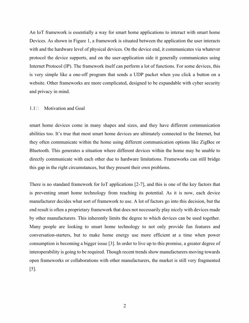
connected together. This forces one node to be both a master and a slave node depending on which
piconet one is referring to. On the right of the figure, two masters are connected via a shared slave
node.
Figure3.BluetoothScatternettopology.ItshowsseveralpiconetsbridgedtogetherbyasharedSlavenodeoraMaster/Slave
combinationnode.
The use of piconets and scatternets makes Bluetooth a lot more viable for smart home applications,
where one would expect many different devices connected in a small area. Indeed, one of the main
advantages of Bluetooth is that smart phones, tablets and laptops frequently have built-in Bluetooth
support. This allows for device manufacturers to develop companion apps that add functionality
using technology the customer is already using.
The major limitation of Bluetooth as an IoT technology is the lack of direct Internet connectivity.
Bluetooth uses a parallel ad hoc network, and can connect many devices as illustrated above, but
this requires proximity and does not provide the remote access that one would see with an IP
connection. To accomplish this, an IP bridge is needed. In the aforementioned case of a
manufacturer having a companion app, the user’s cell phone can serve as the bridge.
The introduction of Bluetooth 4.0 saw a focused effort to make Bluetooth a better fit for IoT
applications. Also called Bluetooth Low Energy (LE), Bluetooth 4.0 sacrificed some speed to
reduce power consumption and thus improve battery life. More importantly, Bluetooth 4.2 (also
called Bluetooth Smart) introduced IP support via something called Internet Protocol Support

7
Profile (IPSP). This essentially adds IPv6 support to Bluetooth. It’s important to note that this does
not provide IP connectivity; it just allows for transmitting IPv6 packets over a Bluetooth
connection. This helps from a security standpoint, but the biggest advantage is that it allows for
Bluetooth to make use of an IP bridge without the need for a specialized app from the manufacturer
to do the packet conversions [9, 11]. In other words, there still needs to be a device with hardware
for both IP and Bluetooth, but it can pass packets from one to the other without the need for
extensive and taxing conversion.
Despite these trends towards making Bluetooth more IoT-friendly, there are still considerable
limitations. First, most Bluetooth connections are still point-to-point, without building an ad hoc
chain of nodes. Also, smart phone support for more recent Bluetooth versions is lacking. Bluetooth
4.2 adds a lot for IoT applications, but not very much for things like wireless audio, which is the
main focus for cell phone makers. Also, even with piconets and scatternets, there is not a true mesh
network solution for Bluetooth, which some view as essential for IoT applications. Security and
privacy is an inherent problem with Bluetooth as well. The physical layer handles both
authentication and encryption with Bluetooth. It generally relies on a simple challenge-response
scheme where a user supplies a PIN (as short as 4 digits long), and that is sufficient to gain most
access [10]. Security can be added into application data as well, but this costs precious space in an
already-constrained system.
The recent trends in the Bluetooth standard are encouraging for smart home applications, but the
adoption isn’t very high yet. The recently-released Bluetooth 5.0 standard shows that they are
continuing in the IoT direction, but it remains to be seen if they can gain the level of support that
is enjoyed by some other options discussed below [12].
2.1.2 IEEE 802.15.4 Standard-based Protocols
IEEE 802.15.4 is a communication standard for low-data-rate wireless personal area networks
(LR-WPANs). The standard defines how the physical and data-link layers should look, but leaves
higher protocol stack layers up to individual communication protocols to define [13, 14]. The
standard provides a few key services that are important from a security standpoint. First, it provides

8
access control via an Access Control List (ACL) maintained by devices to effectively have a white
list of devices that can be talked to. It uses symmetric encryption, with 128-bit AES as the cipher.
Message integrity is assured using a Message Integrity Code (MIC). Lastly, it also provides replay
protection via sequence numbers [14]. Support has also been added for Time-Slotted Channel
Hopping (TSCH) to further enhance privacy, but this is not universally supported [15].
Designed to operate in a noisy environment, the 802.15.4 standard uses Direct-Sequence Spread
Spectrum (DSSS), which minimizes the effect of random noise [14]. This makes it ideal for a
cluttered environment like one would expect in IoT applications. These underlying features of
802.15.4 as a whole provide a stable foundation, on top of which several different protocols have
been built. Many of these protocols are ideally suited to smart home applications because they
provide communication within a house-sized area and use very low power. In the United States,
this most commonly uses the 2.4 GHz band, which can interfere with Wi-Fi [16]. The most
prevalent examples of this are ZigBee and 6LoWPAN.
2.1.2.1 ZigBee Personal Area Network Technology
ZigBee networks have three logical components: coordinators, routers and terminal equipment.
The Network Coordinator is responsible for maintaining all routing information in the system,
there will be exactly one node with this function. There are also secondary routers that maintain
state information with the Network Coordinator to keep current routing information. Terminal
equipment is a passive component on the system. It is not used for routing or any other service
[14, 17].
To fit these logical roles there are two main types of equipment: Full Function Devices (FFD) and
Reduced Function Devices (RFD). Full Function Devices make up the coordinators and routers in
the system. While there is only one Network Coordinator at any given time, if it goes offline
another FFD can become the Network Coordinator to keep the system up. Reduced Function
Devices are generally terminals on the system, though routing may be included in some
circumstances [14].
9
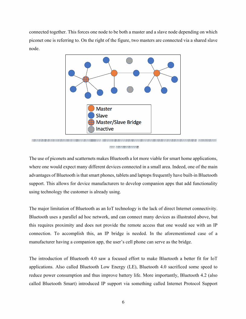
ZigBee provides support for both conventional star network topologies and mesh networking.
Figure 4a shows a standard star configuration, with a Network Coordinator as the central node and
every other node connecting radially out from it. This star configuration could also be expanded
with trees from each router. An important thing to note is that the central node must be the Network
Coordinator in this configuration, so if the central node goes down the system is down. Figure 4b
shows a generic mesh network configuration. In this scenario, the Network Controller still makes
routing decisions, but other routers are capable of assuming that responsibility if the Coordinator
goes down. In IoT applications, this latter mesh configuration is more common because it is robust
and allows for nodes to come and go [10]. Both topologies can be used in connected ZigBee
networks.
Figure4.ZigBeeNetworkTopologies.Theyshowastarnetwork(a)witheachnodedirectlyconnectingtotheCoordinator,anda
meshnetwork(b)withnodesconnectedtoeachotherthroughRouters.
ZigBee has a few different security modes: non-secure, access control mode and safe mode. Non-
secure mode is exactly what it sounds like, no security is enabled at all. Importantly, this is the
default mode. Access control mode works essentially as a simple firewall, allowing and
disallowing traffic to and from particular devices. Safe mode is the most secure, and makes full
use of the four 802.15.4 features described in 2.1.2. Key distribution is not specified in the 802.15.4
standard, so it is up to individual implementations. In ZigBee, each device has a shared master
key, which is used for generating temporary keys. A Link key is generated for secure unicast
messages between nodes, and a network key is shared by all devices to protect broadcast messages.

10
The Network Coordinator acts as a Trust Center, and is responsible for key distribution when
necessary. This key distribution system is viewed as a weakness [14].
2.1.2.2 6LoWPAN Low Power IPv6 Technology
Both ZigBee and 6LoWPAN are built on the same physical and data-link layers, this means they
use the same physical hardware. The difference is the implementation of the higher levels. ZigBee
has been around longer and is supported by more devices, but 6LoWPAN is easier to use with the
Internet. This is because 6LoWPAN is essentially a low power version of IPv6. This mimicking
of IP formatting allows it to communicate with things outside the local network using a simple
gateway. ZigBee can also do this, but the conversion required at the gateway is more involved and
adds overhead [15, 18].
6LoWPAN has an adaptation layer that is between the link layer and network layer, and it provides
a few solutions that allow for IPv6 traffic to translate to 6LoWPAN traffic relatively seamlessly.
It fragments and reorders IPv6 packets to account for smaller packet size, compresses the headers
as much as possible, allows for stateless addressing, and provides infrastructure for mesh routing
[15]. This sounds like a lot, but it’s significantly easier than translating from Bluetooth or ZigBee
to and from IPv6.
One key part of IPv6 is that each device is directly addressable due to the large address space. This
is often done with Medium Access Control (MAC), which uses part of a devices hardware address
to build a unique IP address. This has privacy implications because it could allow for a particular
device to be tracked. DHCPv6 addresses this by assigning IP addresses instead of allowing devices
to build their own [15].
In terms of native security and privacy, 6LoWPAN does quite well. In addition to the protections
native to 802.15.4, it also has many of the protections built into IPv6. At the network layer, this
includes native support for IPsec. This has two primary protocols, Authentication Header (AH)
and Encapsulating Security Payload (ESP). AH essentially adds a separate header that can be used
to both authenticate the source of the message and its integrity. ESP provides encryption,
11
authentication and integrity assurance by adding headers and trailers. Either of these protocols can
be used in either Tunnel or Transport mode, the former of which adds yet another header. The
common theme with these modes is that they require adding more and more overhead, which often
makes IPsec implementations on lightweight 6LoWPAN cumbersome [15].
More security can be added at the application layer in the form of DTLS, which is based on TLS
but applied to UDP rather than TCP packets. This has several levels of protection: No protection,
each device can have a list of pre-shared keys for communicating with other devices, there can be
a simplified public key setup with no certificate authority, or there can be a full public key setup
with a x.509 certificate verified by a certificate authority [15].
When implemented correctly, 6LoWPAN has more built-in security than any other options in the
lightweight sector. There is a price to this. Despite having the same bottom two layers as ZigBee,
6LoWPAN ends up having a lot more overhead. However, it may be ideal for devices that wish to
bridge the gap between smart home network and the Internet because the conversion to and from
IP is so painless. 6LoWPAN also has the advantage of being able to work on different physical
layers. It is most often seen with 802.15.4, but can also be used on Ethernet or Wi-Fi. Both ZigBee
and 6LoWPAN work well for making a mesh or star network within a home, and it’s not
uncommon for devices to have libraries to support both protocols.
2.1.3 Z-Wave Low Energy Technology
Z-Wave is very similar to ZigBee, but it is not based on the 802.15.4 standard. This means it works
on different hardware, but the idea is very similar. It is designed for low-power short-range
communication and it generally is used to make a mesh network. Like ZigBee, each device is a
node. The short range makes it easy to set up a mesh network that will encompass a whole home
while avoiding strong signals that could interfere with a neighbor’s mesh. Each device does also
have a Network ID associated with it, which further prevents overlap with neighbors [17].
A Z-Wave mesh network can contain up to 232 devices, which can be categorized as controllers
and slaves. Slaves are analogous to Terminal Equipment in ZigBee; they receive commands and

12
execute instructions. They can send data, but only to their masters as they have no routing table.
The Primary Controller has the master routing table, which is shared with other controllers.
Secondary Controllers maintain state with the Primary Controller to keep current routing info [17].
When a Z-Wave device wants to communicate with another, it first attempts direct communication.
Only if this fails does it pass the packet to a controller. Messages are limited to 5 hops, with 2
being considered optimal. To deal with packet collisions, a random delay is used before
retransmitting if a collision is detected. Devices can also use a power save function and go into a
sleep mode, whereby it only checks in for messages between idle periods [16].
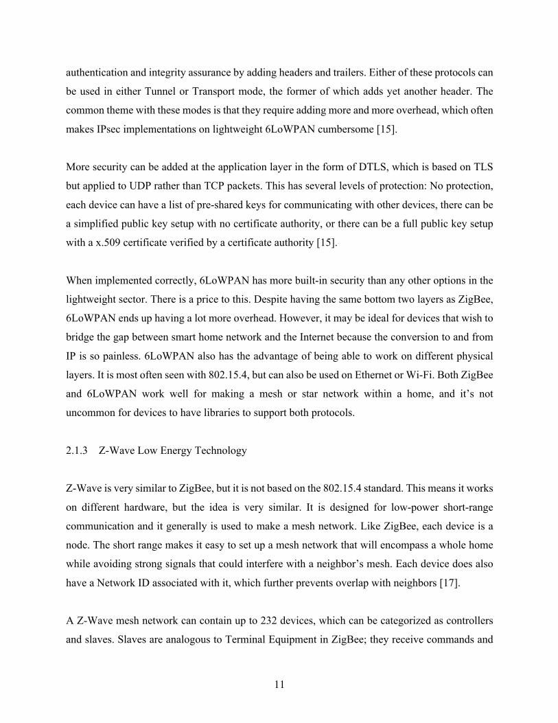
In terms of the Z-Wave packet, it is very lightweight and very simple. Figure 5 shows its protocol
stack. The physical layer consists of RF signals that operate at a frequency of 908.42 MHz. This
makes it less susceptible to interference in some circumstances than ZigBee and 6LoWPAN, both
of which usually operate in the 2.4 GHz range that is shared with WiFi and other signals [16, 19].
The Transport Layer uses a simple ACK system to ensure integrity and allow retransmission. The
Routing Layer assembles the mesh described above, and the Application Layer carries command
info and the payload. Recent Z-Wave chips do include support for AES, and key distribution is
done during initial network joining. This has proven to be a weak point in the system, as there have
been Z-Wave devices compromised due to poor key distribution implementation [19].
13
Figure5.Z-WaveProtocolStack.ItshowsRFatthePhysicalLayer,ACK-basedretransmissionschemeattheTransportLayer,
meshsetupattheRoutingLayer,andcommandsattheApplicationLayer[19].CourtesyofSensePostUKLtd.Ó2015.
Z-Wave is ideal for smart home applications within the home, and it is one of the most popular
approaches. However, it does take extensive conversion at a border router to connect the mesh
network to the Internet. This inherently limits its use. It is also a proprietary protocol, and all Z-
Wave chips come from the same manufacturer. As such, it has not been subjected to the same level
of scrutiny that has been seen on protocols stemming from IEEE standards. There is a general lack
of security features built in, but when implemented properly they may be sufficient for most
applications.
2.1.4 Wi-Fi and Ethernet Technology
Most smart home setups involve a Wi-Fi or Ethernet connection at some point. It is very common
to have one node with a wireless or hard connection to a router, then a local network built on
another technology and protocol. This allows for the system to connect to the Internet to send
information and receive commands, but doesn’t require that each device have the larger overhead
associated with IP connectivity. If implemented smartly, manufacturers can save money on unit
cost and significantly reduce power requirements for connected devices. However, poor design
can lead to network clutter or problems with insufficient ports.
14
The Internet connection can be used to directly send commands to devices and receive information
from them, but more often than not a cloud service is used. This essentially just involves both the
user application and smart home devices communicating directly with a server being hosted
outside the home. Cloud services are important to smart home technology. This is for a number of
reasons. First, it’s easier to ensure 100% uptime with a remote server being professionally
monitored [20, 21]. It also allows for communication to be encrypted and authenticated using tools
like public key cryptography [22]. Some of the burden is also removed from the end user, they
don’t have to set up and maintain a server [20].
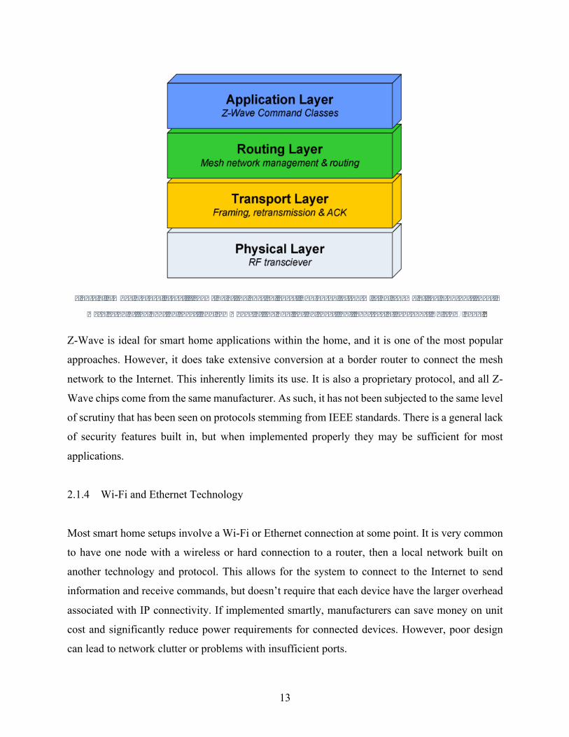
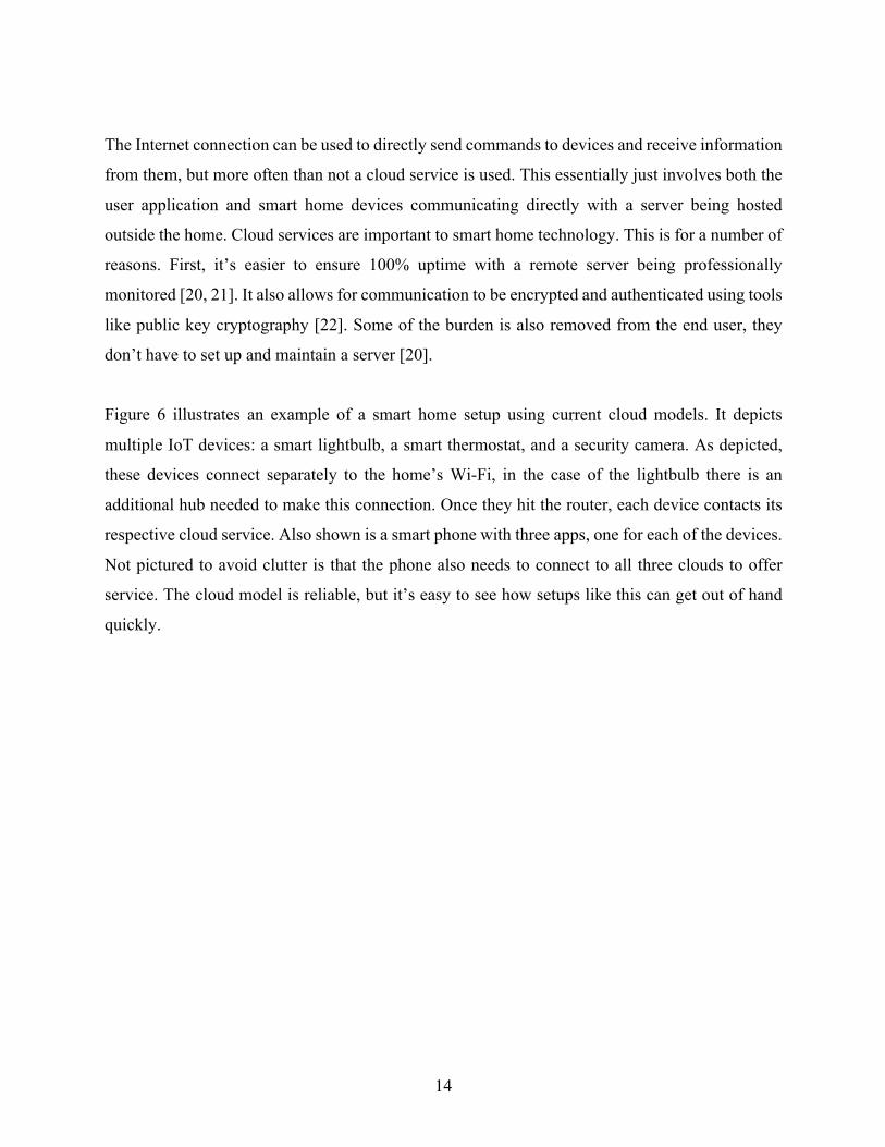
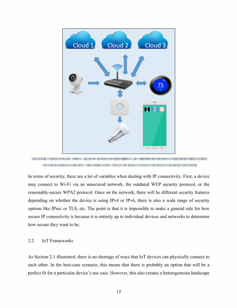
Figure 6 illustrates an example of a smart home setup using current cloud models. It depicts
multiple IoT devices: a smart lightbulb, a smart thermostat, and a security camera. As depicted,
these devices connect separately to the home’s Wi-Fi, in the case of the lightbulb there is an
additional hub needed to make this connection. Once they hit the router, each device contacts its
respective cloud service. Also shown is a smart phone with three apps, one for each of the devices.
Not pictured to avoid clutter is that the phone also needs to connect to all three clouds to offer
service. The cloud model is reliable, but it’s easy to see how setups like this can get out of hand
quickly.
15
Figure6.Non-IntegratedsmarthomeSetupwithCloudServices.ItshowsmultipleIoTdevicesconnectingtotheirrespective
cloudserversthroughthehomerouter,andasmartphonewithseparateappscorrespondingtoeachdevice.
In terms of security, there are a lot of variables when dealing with IP connectivity. First, a device
may connect to Wi-Fi via an unsecured network, the outdated WEP security protocol, or the
reasonably-secure WPA2 protocol. Once on the network, there will be different security features
depending on whether the device is using IPv4 or IPv6, there is also a wide range of security
options like IPsec or TLS, etc. The point is that it is impossible to make a general rule for how
secure IP connectivity is because it is entirely up to individual devices and networks to determine
how secure they want to be.
2.2 IoT Frameworks
As Section 2.1 illustrated, there is no shortage of ways that IoT devices can physically connect to
each other. In the best-case scenario, this means that there is probably an option that will be a
perfect fit for a particular device’s use case. However, this also creates a heterogeneous landscape
16
where some families of devices can easily communicate with each other while others cannot. This
is where the idea of an IoT Framework comes in. The idea of a framework is to provide a way for
different devices to talk to each other and coordinate their actions. To do this effectively, a
framework needs both a physical way to bridge the different communication standards and a
semantic way for devices to find a common language.
Figure 1 showed an IoT framework as a simple box between physical devices and applications.
However, it performs a lot of functions that are essential for smart home technology. First, it
converts messages to and from different formats based on protocols being used. It is also
responsible for things like security and device discovery. It is the framework that determines how
easily other devices can be connected, and there is no shortage of frameworks.
The number of communication options is the most basic obstacle to making a unified framework
that can support all smart home devices. Either every manufacturer has to agree on a specific
protocol to use or there needs to be a framework that can work with all communication protocols.
There are many approaches to IoT frameworks, but this section will break them into two
categories: Proprietary frameworks and Universal open-source frameworks. The following
sections will examine current offerings in each category, followed by more general comparisons
of security and ease of use between the frameworks.
2.2.1 Proprietary Frameworks
Most smart-home devices that are sold today are designed to work within a proprietary ecosystem.
This allows for manufacturers to control how devices are used and gives users incentive to stick
within a product family to avoid having multiple independent setups that can’t communicate. The
scope of the framework can vary widely. The proprietary model is the oldest model, and many
companies have their own framework that supports only their devices. This has started to change
recently [5]. Recognizing that customers want devices that work together, many large companies
have invested in joint frameworks. This allows for devices from different manufacturers to
communicate, but it is a very specific list of devices. Some of the biggest proprietary models are
described below.
17
2.2.1.1 Apple HomeKit
Apple is known for having a unified ecosystem where iPhones, iPods and Macs work together.
Their IoT framework, HomeKit, is largely an extension of that. It is used to connect iOS, tvOS and
watchOS devices to smart home devices [23]. This provides an inherent limitation to its use
because it narrowly restricts the types of clients that can utilize it.
The central focus on HomeKit is a user’s Home Configuration, which provides for naming and
organizing smart home devices in a user’s home. There are several logical containers in a home
configuration. On the top is a ‘Home’, of which a user may have several. Within a Home there are
‘Rooms’ [23]. ‘Accessories’ refer to particular devices and they are assigned to a Room within a
Home. ‘Services’ represent the functionality of Accessories; an example would be power or color
for a smart light bulb. This is a very similar structure to Samsung’s SmartThings (See 2.2.2.1),
except that HomeKit also has optional ‘Zones’, which serve as collections of Rooms [23].
Essentially HomeKit is a service that allows for developers to make third party apps that can
discover compatible devices, access the home configuration database and issue commands to smart
devices. Apple lists over 100 devices with support or support coming soon [24]. They do not sell
physical hardware, rather they rely on individual devices to get their own IP connection. Using a
public API, Apple coordinates setup and control of compatible devices in one app. It is a relatively
new framework, and support is not widespread yet [25]. Some device manufacturers have pointed
to Apple making hardware-specific requirements for HomeKit certification, which both delays the
roll-out and serves as a disincentive to prospective HomeKit devices [26].
By opting not to use a hub, Apple is ceding a lot of control over communications security to
individual manufacturers and multiple cloud services. They do require that devices securely
authenticate with the app, and any app communications are encrypted [23]. The real strength of
this framework is that it allows for apps and devices to make use of popular apple features like Siri
for voice interactions. It also leverages the large market share that Apple enjoys in smart phones.

18
2.2.1.2 Google Weave
Google is approaching IoT frameworks differently from other companies. They are not trying to
accommodate existing devices, rather they are investing in software options for new devices.
Google Weave is a cloud communication protocol [27]. It is made up of two components: The
Weave Device SDK and the Weave Server. The SDK is a lightweight development kit that is
supported on Linux, Qualcomm and Marvell devices [28]. The Weave Server is a cloud service
that is maintained by Google. It provides services like device registration, state storage and
integration with other existing Google services, like voice support via Google Assistant [28].
In Weave, supported devices must provide a description of their components and traits. A
component can be something like a power switch or a lock, while a trait refers to a state of a
component. In this example, on/off would be traits of the power switch while locked/unlocked
would be traits of the lock [28].
A key part of this is that these components and traits are designed to be common to the device type
[28]. For example, a smart light bulb may have traits for on/off, or color and brightness, but it
won’t have traits for volume. This is perfectly intuitive because volume control on a lightbulb isn’t
something that is seen, but if a manufacturer comes out with a lightbulb that includes a built-in
speaker, its speaker features will not be supported by Weave. Essentially, many devices will lose
unique functionality when accessed through Google Weave communication. This is an effort by
Google to address not just the technological hurdles of device communication, but also the
semantics of understanding what features are offered by what devices.
There are a few considerations for Weave. First, it is very new and support is lacking. The only
types of devices that are supported now are lights, outlets, thermostats and wall switches. It is also
strictly an IP framework, so non-IP devices must first get connected through a bridge before using
Weave. A huge strength of Weave is that it lowers the cost of entry for IoT device development.
Google provides all the tools and even the cloud infrastructure on which the service runs. To get a
device certified, a manufacturer need only submit some paperwork, run automated suite of tests to
ensure compatibility and submit the results. Security is something of a weak spot for Weave. It
19
supports and recommends many security features like TLS and automatic updates, but these are
guidelines and not required [28].
2.2.2 Open-Source Frameworks
A lot of Open-Source frameworks have emerged recently, some with significant corporate
backing. The strength of an Open-Source framework is that it is user-expandable and
manufacturer-neutral. This means that a consumer can’t get locked into a product family just
because they own other devices in that family. The tradeoff is that the quality is heavily dependent
on the developers, with active communities being essential. Products are often significantly less
polished than proprietary offerings, and setup and use is often more complicated. Below, some of
the top open frameworks are discussed.
2.2.2.1 Samsung SmartThings
Samsung’s entry into the IoT framework race is SmartThings. It is predominantly a hub-based
system, with users having to purchase a hub from Samsung. This is a small device that costs $99
containing the hardware to connect to ZigBee, Z-Wave and Bluetooth 4.0 (though this
functionality is not yet available). The hub connects to a home’s router and interacts with the
Samsung cloud. Apps can be run locally from the hub or via the cloud connection. It should be
noted that the hub is not necessary if all home devices have an IP connection and can be operated
remotely, but most installs will have the hub [29].
Like many frameworks under discussion, SmartThings has a significant cloud component.
Samsung hosts a cloud service, which has the advantage of offering a constant connection that
Samsung can regulate. Though the setup is proprietary, third-party developers can make apps that
are then hosted on Samsung’s cloud service [25]. Third party app development is designed to be
relatively straightforward, though it does rely on a programming framework that uses the ‘Groovy’
programming language [29]. Samsung also provides a web-based IDE that doesn’t tie a developer
to a particular Operating System, and a simulator that lets developers try their code out even
without physical devices [29].
20
SmartThings development has two major parts, SmartApps and Device Handlers. SmartApps can
be thought of like rules engines in other schemes. A simple example would be something like
turning on lights when it gets too dark [29]. This is tying together a smart light and either an
ambient light sensor or weather data. Lots of small rules like this are available out of the box, and
it is designed to make it easy for one to make their own rules out of device attributes. Device
Handlers are used to add a new device to SmartThings. To keep with the lightbulb example, if
someone wanted to use the aforementioned SmartApp with an unsupported light bulb, they would
need to make a Device Handler for the bulb. This handler would have to define the light’s ‘on’
function, and generate necessary network traffic to turn on the bulb.
In addition to Samsung, there are other major manufacturers like Honeywell and Bose that also
make SmartThings-compatible devices. However, it is an Open-Source framework that is designed
to be expanded to any current or future device that allows for third-party control. Samsung does
not impose security requirements on developers or devices, but it has some structural security
features. First, communication between the hub and cloud is encrypted as one would expect.
Individual apps also ask for permissions to operate, and users can configure this aspect. This is not
unlike the process of installing a cell phone app and it confirming with the user that they are okay
with the required permissions [25, 30].
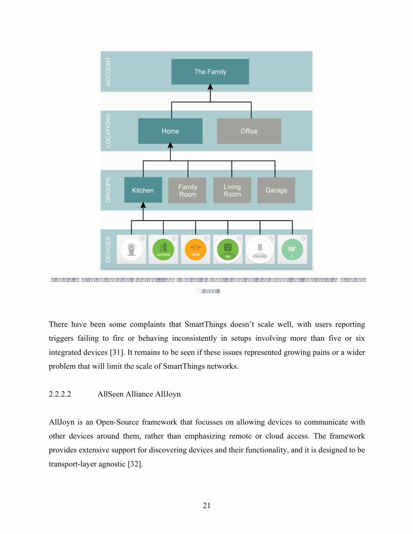
SmartThings also uses the idea of containers to both organize devices and provide security barriers
[29]. This is illustrated in Figure 7 below. The top level has a user’s account, which can be tied to
multiple locations, each of which generally has its own hub. Groups are effectively locations
within locations, like rooms in a house. Devices are tied to a group; each group can have multiple
devices, but a device can only be in one group.
21
Figure7.SmartThingsContainerHierarchy.ItshowsDevicesinGroupsinLocationsinanAccount[29].CourtesyofSmartThings
Ó2017.
There have been some complaints that SmartThings doesn’t scale well, with users reporting
triggers failing to fire or behaving inconsistently in setups involving more than five or six
integrated devices [31]. It remains to be seen if these issues represented growing pains or a wider
problem that will limit the scale of SmartThings networks.
2.2.2.2 AllSeen Alliance AllJoyn
AllJoyn is an Open-Source framework that focusses on allowing devices to communicate with
other devices around them, rather than emphasizing remote or cloud access. The framework
provides extensive support for discovering devices and their functionality, and it is designed to be
transport-layer agnostic [32].
22
The Framework consists of Apps and Routers. Apps can only directly communicate with Routers,
making them analogous to terminal equipment in ZigBee. Multiple Apps and Routers can be
present on a single piece of hardware, or they can be spread across multiple devices. AllJoyn Apps
consist of the actual App code, as well as a core library and services libraries [32]. AllJoyn is
primarily used with a local network using Wi-Fi or Ethernet, but bridges to ZigBee or Z-Wave can
be implemented as well.
The current version of AllJoyn also includes an onboarding framework to perform initial setup on
compatible devices. This novel approach uses a device that is already on the network (the
‘onboarder’) to share connectivity information with a device seeking to connect (the ‘onboardee’)
[32]. First, the onboardee sets up a Wi-Fi access point, and broadcasts its SSID starting with “AJ_”.
The onboarder connects to this access point and sends it details to connect to the wireless network.
Then both devices switch to the wireless network, and the onboarder considers the process to be
complete when it gets an introduction announcement from the onboardee. This provides a user-
friendly way to get devices set up.
AllJoyn has a rather unique approach to security and authentication. AllJoyn uses a simplified
version of public key cryptography for every component in the system (both hardware and
software), but the “Certificate Authority” in the system is managed locally during setup [25, 33].
This makes setup a bit more challenging, but it is a somewhat unique approach. All security is
done at the application layer, and it is optional [32]. In late 2016, AllJoyn announced that it would
be merging with IoTivity. IoTivity has indicated that future versions will be fully backwards-
compatible with AllJoyn.
2.2.2.3 Linux Foundation IoTivity
IoTivity is an Open-Source framework developed in collaboration between Samsung, Intel, and
Microsoft. It was designed specifically with interoperability in mind. It covers most existing
communications protocols like Wi-Fi, ZigBee and Z-Wave; and it coordinates some core
functionality like device discovery and message formatting. It is one of the more ambitious
23
approaches in that it is designed from the ground up to be a universal solution for all IoT needs
going forward [34].
IoTivity framework APIs are available in many common programming languages like C, C++ and
Java. It uses wrappers on top of existing communication, and it consists of four key parts:
Discovery, Data Transmission, Data Management and Device Management [34]. IoTivity consists
of Servers and Clients. Servers maintain state information and control devices, while Clients access
resources via a Server. Devices can be connected indirectly to IoTivity servers via plugins that
perform necessary wrapping and unwrapping to translate messages.
Clients and Servers communicate using a RESTful architecture. This is well suited for a
heterogeneous environment like the smart home, where it may not be obvious what sort of options
are available for devices. In this sort of setup, the Server will be able to provide any necessary
information to Clients by responding to basic REST like GET or PUT [34]. In terms of security,
there is built-in security with multiple options for varying levels of trust [25]. However, this
security is not mandatory, and the numerous options make it difficult to generalize the level of
security found in a typical implementation.
2.2.2.4 OpenHAB
OpenHAB is a popular open framework for home automation without corporate backing. It is
designed to be technology neutral, supporting multiple vendors and communications protocols
[35]. At its core, OpenHAB is a hub-based system. The hub is not proprietary; it can run on any
device that can support a Java Virtual Machine (JVM). Like many Open-Source frameworks,
OpenHAB is designed to integrate existing devices together under one common control scheme.
To do this, OpenHAB relies on user-developed Bindings, which are effectively library modules
that allow it to control individual IoT products or families of products. At the time of writing, there
are 231 Bindings available for use [36]. These Bindings range in complexity from a simple module
that lets a user know when a particular Bluetooth device is in range, to a Binding that supports all
Nest devices via their API.
24
OpenHAB is designed to be a system of systems. That is to say, it does not provide a new way for
devices to communicate, it simply sits in the middle and performs conversions as needed. Users
can decide how much capability they want to give their OpenHAB hub. Someone can simply use
an old computer to host the OpenHAB service, or a lightweight computer like a Raspberry Pi, but
if they want it to be able to use Bluetooth, ZigBee or Z-Wave they will need to purchase hardware
adapters to support these communications. Also, OpenHAB will assume that any initial setup for
a device is already complete. For example, if a user wants to set up a smart lightbulb with
OpenHAB controls, the bulb must already be on the home network using whatever method the
bulb’s manufacturer has established to accomplish that. Essentially, OpenHAB is a solution for
the daily use of a system rather than setting up a system [35].
In terms of OpenHAB’s inner workings, there are a few core concepts. OpenHAB utilizes the
concepts of Things and Items. Things are usually physical devices with multiple different functions
available, but it can also be a virtual service that serves as a collection of different functions. Items
are attributes that can be controlled. In the example of a smart lightbulb, there may be an Item for
color, power and brightness. These are the settings that users manipulate to control devices [35].
There is also the idea of Sitemaps, which OpenHAB uses to make user interfaces for manipulating
Items. Sitemaps are set up by editing a configuration file where users manually declare and name
buttons, slider and other GUI elements. Lastly, OpenHAB has a Rules file, which is where the
automation comes in. The Rules file is also configured manually in a configuration file.
One of the most important things to note about OpenHAB is that it is a framework in transition. It
has had a reputation for being not very user friendly, and it’s easy to see why with all of the manual
configuration that needs to be done [30]. However, this appears to be something that OpenHAB is
working on. OpenHAB 2.0 was introduced in early 2017, and it has some major changes. The
concept of Things described above actually started with OpenHAB 2.0. This was in response to an
issue where individual bindings were done in Item configuration files. This was not very user
friendly, and it also prevented OpenHAB from performing robust error checking on configuration
files due to the varied nature of Bindings. OpenHAB also introduced new GUIs to help get away
from textual configuration. The new PaperUI allows both the control and initial setup of devices
without editing files. However, it is a work in progress and usually some file editing is needed
25
[35]. OpenHAB also changed things under the hood, splitting configuration into several separate
files for Things, Items, Sitemaps, Rules, etc. While these changes certainly have potential to
improve the user experience, they are significant enough changes to make OpenHAB 2.0 not fully
backwards compatible. This is a problem, as it limits the number of supported devices based on
which version of OpenHAB a user is running. This will undoubtedly be resolved as soon as the
old Bindings are converted, but in the meantime, some functionality is lost.
2.2.2.5 Other Open-Source Frameworks
There are countless other similar approaches for open frameworks, and they have common themes.
Most approaches rely first on merging the different communications protocols. Usually this
involves some kind of hub to either process communication or encapsulate messages in a uniform
format [2-7]. This gets devices on the same page, but many devices need to communicate with
their cloud services for proper functionality. Open-Source frameworks address this using public
API’s for devices, any devices that don’t provide this can’t be supported without a degree of
reverse engineering. Some frameworks include more-advanced features like conflict resolution
when different rules result in competing instructions and erratic behavior, but this level of detail
is not yet common [37].
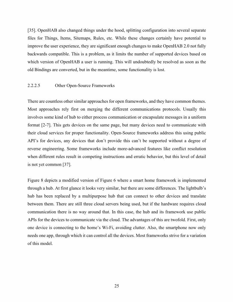
Figure 8 depicts a modified version of Figure 6 where a smart home framework is implemented
through a hub. At first glance it looks very similar, but there are some differences. The lightbulb’s
hub has been replaced by a multipurpose hub that can connect to other devices and translate
between them. There are still three cloud servers being used, but if the hardware requires cloud
communication there is no way around that. In this case, the hub and its framework use public
APIs for the devices to communicate via the cloud. The advantages of this are twofold. First, only
one device is connecting to the home’s Wi-Fi, avoiding clutter. Also, the smartphone now only
needs one app, through which it can control all the devices. Most frameworks strive for a variation
of this model.

26
Figure8.IntegratedsmarthomeSetupwithCloudServices.ItshowsmultipleIoTdevicesconnectingtotheirrespectivecloud
serversthroughacommonhub,andasmartphonewithasingleappforalldevices.
2.2.3 General Security and Privacy of Frameworks
Increased connectivity of home devices offers a lot of new functionality that consumers want, but
it’s not without its risks. Consider the examples of digital video recorder (DVR) and security
cameras. A DVR that is connected to the Internet may allow users to set timers using their phones
or a website, it may even allow them to stream video from their house to their mobile device.
Internet-connected security cameras offer peace of mind by alerting a user when there’s motion at
home and streaming a live feed to their cell phones to help them determine if they’re being robbed
or the cat is moving. These are great features that a lot of people want, but these examples were
27
not chosen at random. These products and others were involved last year in massive Distributed
Denial of Service (DDoS) attacks on web services [38].
These attacks occurred because enough devices had been compromised and formed into a botnet,
which is essentially a bunch of computing devices that can be used together to perform distributed
attacks [38]. Security is a major concern, particularly when one remembers the scale of smart home
technologies; billions of new consumer IoT devices are expected to be connected in the next few
years. Computers and even mobile computing devices generally have some degree of malware
protection, but the IoT landscape is quite varied in its protection. There are several factors that
make smart home and general IoT devices particularly vulnerable.
2.2.3.1 Varied Landscape of Devices
Initially, it may seem that having different frameworks and communication protocols provides a
measure of security. After all, an attacker would have to account for more scenarios. However,
this is security-by-obscurity, and it is not an effective solution. Often attackers don’t need to
compromise an entire system from top to bottom, they may just need a foothold, and the weakest
link will suffice.
In general, this is less of a concern in unified frameworks such as proprietary models. These
frameworks usually have set security policies that apply across the board. Open-Source options,
however, are often forced to implement whatever security is required for a particular device. If the
framework connects multiple devices from multiple different manufacturers, it is very like that
individual devices will have differing levels of security. This can lead to a scenario where part of
the smart home web traffic is encrypted, and part is plaintext. Many frameworks give the option
to add security where it doesn’t exist already, but this usually only affects communication between
applications and the smart home hubs in the home. Communication from the hub to devices or to
various cloud services cannot usually have additional security added [33].
2.2.3.2 Tendency Towards Over-Privilege

28
In information security, two related concepts are the idea of authentication and authorization.
Authentication is used to verify an entity is who they claim to be. Authorization refers to the level
of access an entity has. Privileges are directly tied to the idea of authorization. When installing an
app on a smart phone, it will ask the user if they want to allow the app to access their address book
or camera or whatever else the app needs. Once a user agrees, they are agreeing that the app
reasonably needs that access and explicitly granting the access. Increased privileges have more
control over a system, and if not managed properly it can completely cede control of a device.
Different frameworks handle privileges differently, but the distinct trend is to give move privileges
than are reasonably needed to perform an assigned task [25]. This is a dangerous situation because
it can allow the injection of back doors, or be used for any number of undesired activity.
Apple’s HomeKit framework uses what they call “accessories” and “services” [25]. Accessories
are IoT devices, while services are actions associated with devices. Apps require permissions to
control devices, but when permissions are granted, it is at the “home” level [25]. This means that
if an app wants access to a particular device, it gets access to everything associated with the user’s
“home.” This inherently gives permissions to control devices that are unrelated to an app’s
function.
IoTivity does have built-in security, but it is not enabled by default. It does support multiple levels
of security when enabled, but permissions are established during initial configuration and tied to a
device’s ID [25]. This is similar to AllJoyn’s approach for permissions. AllJoyn “apps” maintain
a whitelist of other “apps” with permission to interact. In AllJoyn, the term “app” is used to refer
both to software applications and devices themselves. Default permissions give complete access
to an “app”, but this can be manually fine-tuned to be more restrictive [25].
SmartThings is primarily a cloud-based framework. Device manufacturers make apps, which are
hosted on Samsung’s cloud service. It is at the discretion of the app developer to request whatever
permissions they want. Users are asked to approve permissions during initial setup, but there is
nothing preventing apps from over-reaching and requesting more access than they need. This has

29
been used to successfully attack SmartThings devices, unlocking a smart lock and impeding
functionality in other devices [30].
2.2.3.3 Encryption of Communication
Most modern frameworks make use of cryptography at some point. In terms of hardware, even
low power device support full 128-bit AES encryption over ZigBee, Z-Wave and 6LoWPAN [13,
16], but the framework doesn’t necessarily make use of it. Devices are generally designed for
functionality, with security being a secondary concern at best. A lot of this is understandable, one
would expect an alarm clock manufacturer to have extensive networking experience. The result is
often a poor implementation.
Consider AllJoyn. As mentioned earlier, they use a unique model where public key infrastructure
(PKI) is used across all “apps” [25, 33]. This may seem an attractive option because PKI can
provide: encryption to make communications unreadable by eavesdroppers, authentication to
make sure “apps” are who they claim to be and not an attacker spoofing, and integrity to ensure
that messages have not been tampered with [33]. However, public key cryptography relies on a
chain of trust, whereby each device has a certificate, and another entity can vouch for its
authenticity. If that entity themselves isn’t trusted, then someone else can vouch for them. The idea
is to form a chain up to a trusted source, the certificate authority (CA). On the Internet, there are a
few trusted CA’s, but in AllJoyn’s model the CA is effectively the end user. When configuring
AllJoyn, the user can set up a list of trusted certificates [25]. Compromising the locally-stored CA
can negate the whole process [33].
Another misuse of cryptography is fixed credentials. Ideally, individual devices would have their
own secret key for symmetric encryption. However, a lot of the time the key that ships with devices
is the same for every device of that type. This provided encryption to obscure messages to a degree,
but does not provide any form of authentication because there is nothing unique to a specific
device.
2.2.3.4 Privacy Concerns

30
Privacy is a more subjective concern. smart home technology inherently involves the generation
of a lot of data, much of it personal. In the past, home automation was done by people running
their own servers stored locally, which gave them considerable control over personal information.
However, with modern cloud implementations, a well-connected house may send and receive data
from a dozen different cloud services. Regardless of data protections, this is personal information
that is being stored outside of the user’s home [25]. A lot of people are uncomfortable with this.
Unfortunately, there is not an easy answer to this. There are still frameworks that require a user to
run a private server (like OpenHAB), but connected devices may still need cloud communication.
This is simply a tradeoff that must be accepted when integrating different devices [33].
Understandably, recent breaches to IoT security and cloud services leave consumers uneasy about
control of their data. The best the industry can do is build strong security, encrypt data so they
themselves can’t access it, and earn the trust of consumers.
2.2.4 General Support and Ease of Use of Frameworks
The last main differentiator between different smart home frameworks is the level of support. This
also includes the ease of use. Part of the advantage that proprietary frameworks have is that they
can design a framework perfectly suited to supported devices. This removes some of the burden
from users by making an intuitive setup and use. Buying one IoT device and downloading its
corresponding app usually provides a very smooth experience. The problems start to emerge when
combining different devices into one Framework.
This was one of the main incentives for large companies to merge their devices into joint
frameworks like IoTivity. It allows interoperability and the development of apps that are easy for
consumers to set up and use. Some open frameworks are quite difficult for the average user to set
up [5]. OpenHAB in particular requires that users set up a server and navigate the terminal, they
walk users through the process but it is outside of most people’s computer abilities. Even their
documentation warns, “Setting up OpenHAB is mainly a job for tech-savvy people - it is not a
31
commercial off-the-shelf product that you plug in and that is ready to go.” [35] There’s nothing
inherently wrong with such an approach, but it limits the user base.
Major corporate backing also simplifies development by ensuring there are professional
developers keeping the framework alive. One of the major pitfalls of many Open-Source
frameworks is the lack of a development community. Some frameworks like OpenHAB have
active forums and users who frequently create new device bindings, but even they suffer from a
lack of devices and incomplete functionality for supported devices [30]. But others have small
development teams and thus very little support.
2.3 IoT Simulation
Simulating Internet of Things technologies is not a new idea. Simulation in general allows for
developers to identify potential pitfalls while there is still time to make changes. IoT simulations
also take a lot of forms. Some simulations may be looking at a specific technology like Z-Wave
and trying to identify bottlenecks in communication by overloading networks, while others might
simply simulate one single smart home device to allow app developers to test their code. This
section will take a brief look at several examples of existing work, identifying strengths and
weaknesses of the approach.
2.3.1 Application Development
Several manufacturers have recognized the need to facilitate third-party app development for their
products. One way to do this is to provide a simulated device that responds exactly as actual
devices would. That said, the degree to which the simulation matches the physical device varies
significantly by company.
One example is Samsung’s SmartThings development simulator [29]. Samsung maintains a device
handler list, which essentially lists every supported device and its supported functionality. In terms
of device simulation, they basically are only checking that commands being sent are valid
commands for the selected devices. This does not in any way emulate actual network traffic or
32
anything similar, rather it seeks to help developers get their syntax sorted out before rolling out
their app.
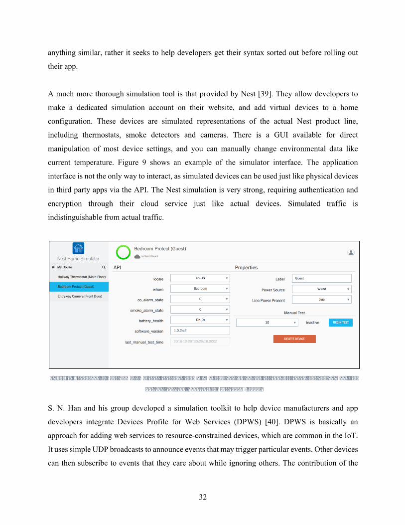
A much more thorough simulation tool is that provided by Nest [39]. They allow developers to
make a dedicated simulation account on their website, and add virtual devices to a home
configuration. These devices are simulated representations of the actual Nest product line,
including thermostats, smoke detectors and cameras. There is a GUI available for direct
manipulation of most device settings, and you can manually change environmental data like
current temperature. Figure 9 shows an example of the simulator interface. The application
interface is not the only way to interact, as simulated devices can be used just like physical devices
in third party apps via the API. The Nest simulation is very strong, requiring authentication and
encryption through their cloud service just like actual devices. Simulated traffic is
indistinguishable from actual traffic.
Figure9.ScreenshotofNestHomeSimulatorInterface.Showssimulateddevicesontheleftandattributesthatcanbemodified
ontheright[39].CourtesyofNestLabsÓ2017.
S. N. Han and his group developed a simulation toolkit to help device manufacturers and app
developers integrate Devices Profile for Web Services (DPWS) [40]. DPWS is basically an
approach for adding web services to resource-constrained devices, which are common in the IoT.
It uses simple UDP broadcasts to announce events that may trigger particular events. Other devices
can then subscribe to events that they care about while ignoring others. The contribution of the
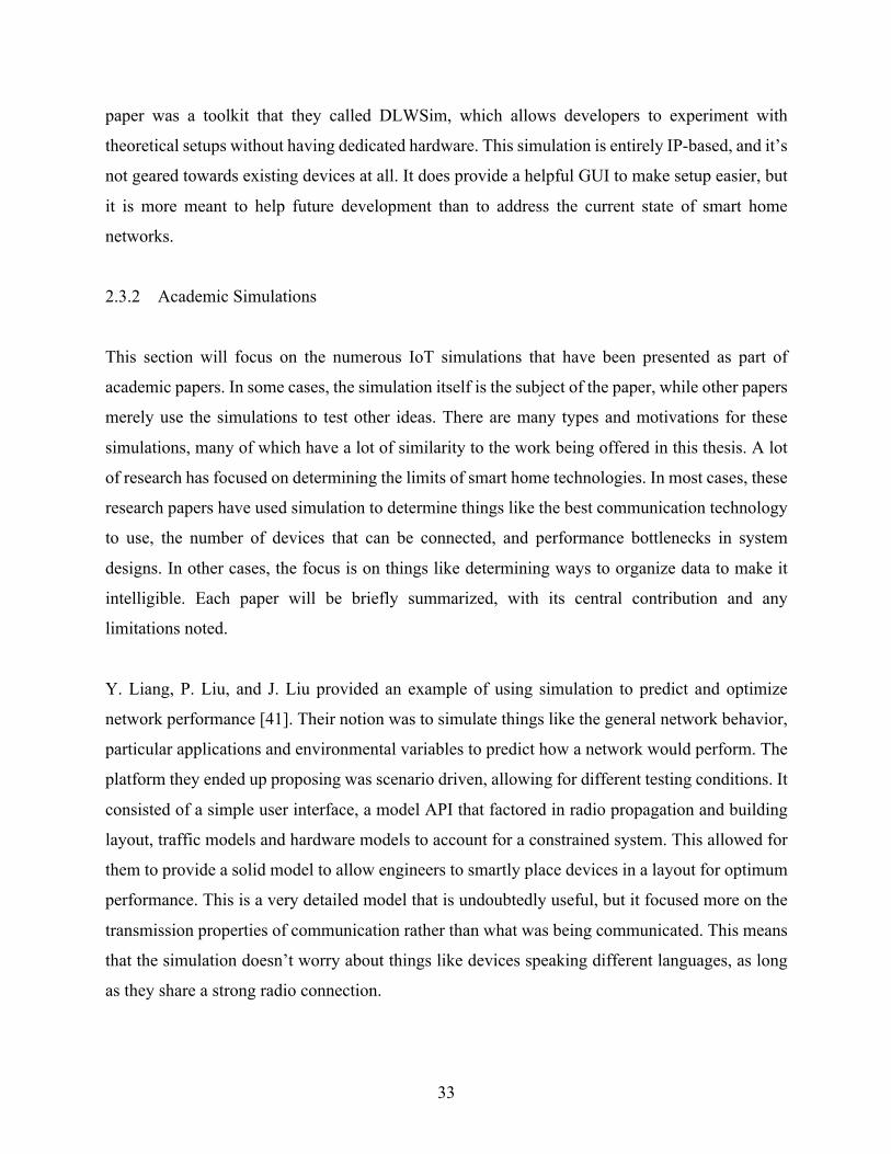
33
paper was a toolkit that they called DLWSim, which allows developers to experiment with
theoretical setups without having dedicated hardware. This simulation is entirely IP-based, and it’s
not geared towards existing devices at all. It does provide a helpful GUI to make setup easier, but
it is more meant to help future development than to address the current state of smart home
networks.
2.3.2 Academic Simulations
This section will focus on the numerous IoT simulations that have been presented as part of
academic papers. In some cases, the simulation itself is the subject of the paper, while other papers
merely use the simulations to test other ideas. There are many types and motivations for these
simulations, many of which have a lot of similarity to the work being offered in this thesis. A lot
of research has focused on determining the limits of smart home technologies. In most cases, these
research papers have used simulation to determine things like the best communication technology
to use, the number of devices that can be connected, and performance bottlenecks in system
designs. In other cases, the focus is on things like determining ways to organize data to make it
intelligible. Each paper will be briefly summarized, with its central contribution and any
limitations noted.
Y. Liang, P. Liu, and J. Liu provided an example of using simulation to predict and optimize
network performance [41]. Their notion was to simulate things like the general network behavior,
particular applications and environmental variables to predict how a network would perform. The
platform they ended up proposing was scenario driven, allowing for different testing conditions. It
consisted of a simple user interface, a model API that factored in radio propagation and building
layout, traffic models and hardware models to account for a constrained system. This allowed for
them to provide a solid model to allow engineers to smartly place devices in a layout for optimum
performance. This is a very detailed model that is undoubtedly useful, but it focused more on the
transmission properties of communication rather than what was being communicated. This means
that the simulation doesn’t worry about things like devices speaking different languages, as long
as they share a strong radio connection.
34
G. Fortino, W. Russo, and C. Savaglio looked at using existing agent-oriented modeling to
simulate the Internet of Things [42]. They started by noting that IoT networks share common
features with the idea of a multi-agent system. This observation allowed for them to use existing
simulation approaches for agent-based systems to apply to IoT simulation. The idea of agent
abstraction is already used for modeling autonomous, intelligent entities that communicate with
each other, which closely resembles some of the ideal characteristics of IoT technology. This
approach considers individual users, devices and computers to be agents. Their simulation
abstracts away the details of lower communication for objects like sensors, using existing
simulation tools like omnet++ to handle this part. This allowed for them to limit their development
to the application layer for the most part. The main contribution of this paper was to show how
one could use existing tools to simulate IoT technology, but the focus was again on optimizing a
network’s overall communication throughput rather than faithfully mimicking varied traffic that
might be seen on a heterogeneous smart home network. Their work was also limited to Wi-Fi as a
medium, though they did note that it could be expanded.
O. Kamara-Esteban, G. Sorrosal, and A. Pijoan developed a smart home simulation architecture
that combined both agent modeling and real world data to provide a better approximation of actual
system performance [43]. Their initial observation was that existing simulations suffered from a
lack of accuracy because they could approximate devices communicating with each other, but
struggled to account for how people would use the system. It is important to note that their focus
was on smart home functionality of devices like solar panels, vents, HVAC units and sewage/water
controls. This focus is on an area that is mostly transparent to users but significantly impacted by
their actions. Essentially, they merged two simulations. First, they used existing agent modeling
techniques to simulate the human element of how people use appliances. Then they used
Simulink/Matlab to model the individual components making up the physical devices as shown in
Figure 10. This detailed simulation gave accurate values for things like power, gas and water use.
While this is an example of using simulation to ultimately optimize efficiency of major appliances,
the central takeaway is the idea of combining separate simulations.
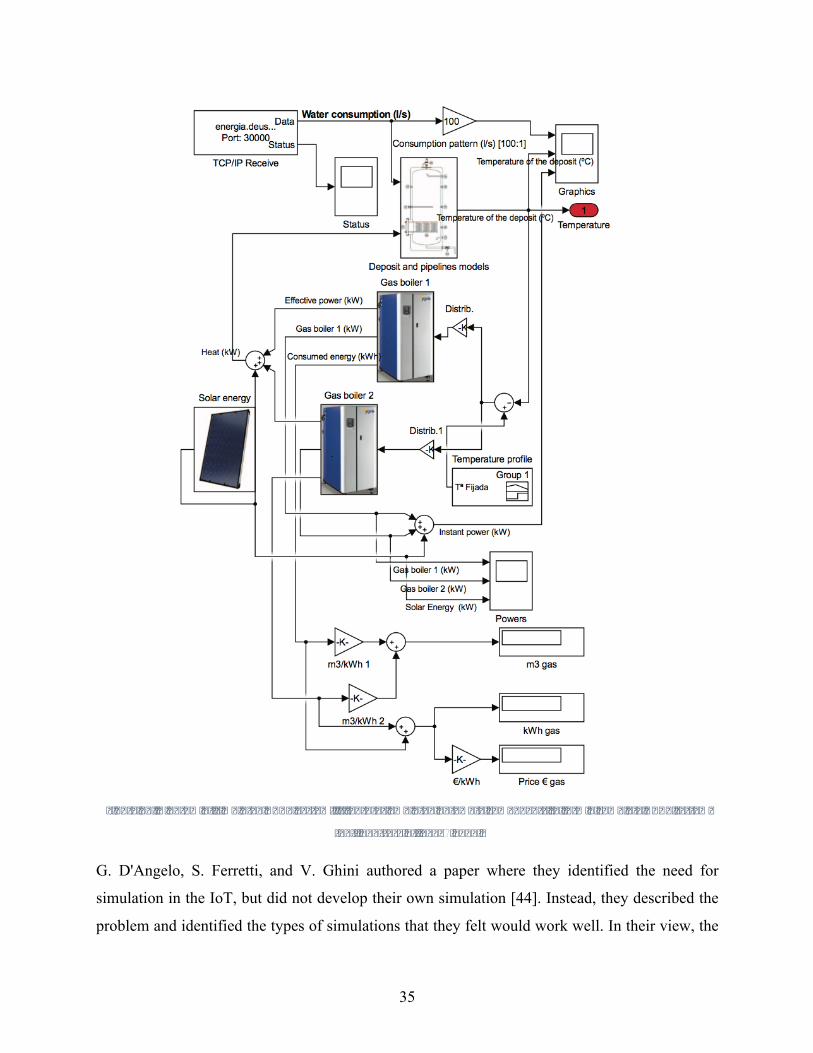
35
Figure10.DiagramofsimulatedHVACSystem.ItfeaturesemulatedhardwarecomponentstoformacompleteHVACsystem
[43].CourtesyofIEEEÓ2016.
G. D'Angelo, S. Ferretti, and V. Ghini authored a paper where they identified the need for
simulation in the IoT, but did not develop their own simulation [44]. Instead, they described the
problem and identified the types of simulations that they felt would work well. In their view, the

36
biggest problem was scalability. They were looking at the IoT at a much larger scale than an
individual home, envisioning millions of sensors connected in a Smart City environment. To
address the challenge of scaling simulation to this level, they subdivided the problem into multiple
levels of granularity. Essentially they ran a high-level simulation on one tier, and more detailed
simulations as needed on other tiers in parallel. They did not address the issue of heterogeneous
communication that one would see in a smart home environment. Like other cited works, they
determined that an agent-based model would be most appropriate for the simulation. The
difficulties involved with combining different simulations were addressed as well, with the authors
noting that different simulation models can be implemented but they have to meet in the middle
somewhere to communicate. This directly related to ideas presented in this thesis, where different
device simulations are merged in an IoT Framework implementation.
K. Rajaram and G. Susanth proposed a system that allowed for a standard computer to emulate an
IoT Gateway [45]. Their work is specifically built around the idea of addressing the heterogeneity
of communication in the IoT. A local computer can be used to collect signals via different
technologies like cellular, Wi-Fi, RF and Bluetooth. The information is then sent to a cloud server,
which interprets the communication and determines an appropriate action. It should be noted that
this setup would still be dependent on connected hardware, so the PC needs to have adapters to
connect to things like ZigBee or Bluetooth. Their proposal is illustrated in Figure 11. The emulated
gateway is labeled “Eml Gateway”, and it is connected to several sensor nodes using different
technologies, and ultimately to the Internet and cloud server for processing. Importantly, this paper
only address how the devices can physically connect to each other. It does not address what the
cloud is doing to actually process the messages. This is the role that a Framework would generally
fill, and it is beyond the scope of their paper.

37
Figure11.DiagramshowinguseofemulatedIoTGateway.EmlGatewayconnectstovarioussensornodesusingdifferent
communicationprotocols,andinformationissenttothecloudforprocessing[45].CourtesyofIEEEÓ2017.
N. Shrestha, S. Kubler, and K. Främling observed that solving the issue of unified communication
does not solve the whole problem [46]. Essentially, they argue that it does not matter if systems
are physically able to communicate if they don’t have a way to integrate data. It’s a question of
how devices use the data they receive. Several Frameworks have addressed this problem. Some
are very open-ended, leaving it up to developers to design functionality that adheres to some
general rules. While other solutions limit the subset of valid instructions for a device based on
what type of device it is. In this case, the authors use an existing approach called Quantum
Lifecycle Management (QLM). QLM is essentially an application-layer protocol that can be
thought of as HTTP for machines. Like HTTP, it gives a simple set of instructions that can be
performed such as read, write and cancel. These are similar to the HTTP notions of GET, PUT,
and DELETE. The payload can be any format one wants, such as JSON or XML. This essentially
would give devices a way to directly query other devices to determine their functionality. One
major benefit of this approach is that it can easily be used in conjunction with other approaches by
simply encapsulating messages. Figure 12 illustrates this idea. It shows several devices connecting
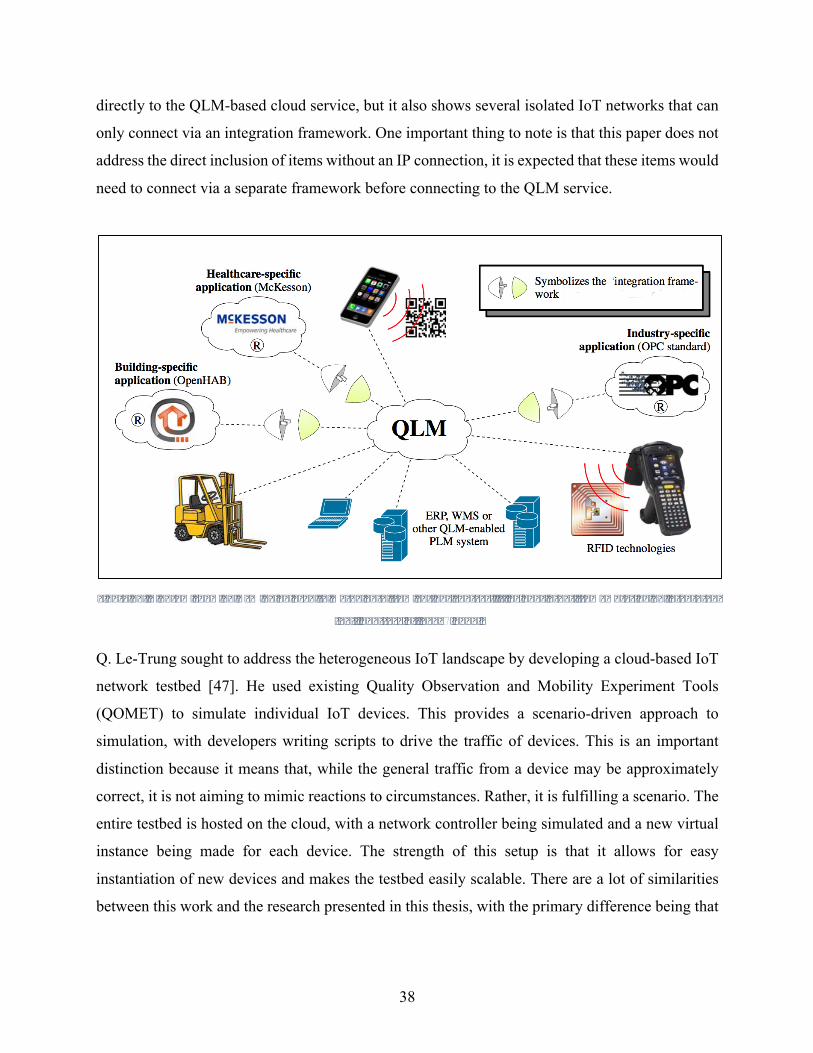
38
directly to the QLM-based cloud service, but it also shows several isolated IoT networks that can
only connect via an integration framework. One important thing to note is that this paper does not
address the direct inclusion of items without an IP connection, it is expected that these items would
need to connect via a separate framework before connecting to the QLM service.
Figure12.DiagramshowingQLMbeingusedtomergedatafromvarioussources.Itincludesotherframeworksbeingintegrated
[46].CourtesyofIEEEÓ2014.
Q. Le-Trung sought to address the heterogeneous IoT landscape by developing a cloud-based IoT
network testbed [47]. He used existing Quality Observation and Mobility Experiment Tools
(QOMET) to simulate individual IoT devices. This provides a scenario-driven approach to
simulation, with developers writing scripts to drive the traffic of devices. This is an important
distinction because it means that, while the general traffic from a device may be approximately
correct, it is not aiming to mimic reactions to circumstances. Rather, it is fulfilling a scenario. The
entire testbed is hosted on the cloud, with a network controller being simulated and a new virtual
instance being made for each device. The strength of this setup is that it allows for easy
instantiation of new devices and makes the testbed easily scalable. There are a lot of similarities
between this work and the research presented in this thesis, with the primary difference being that

39
this thesis is seeking to accurately reproduce the functionality of IoT devices regardless of what
input is sent to them.
A. P. Ríos, V. Callaghan, and M. Gardner focus on the observation that there are a lot of Smart
Spaces, like classrooms, cars, and homes; but they are not yet interconnected [48]. This is a
recurring theme in many papers focused on the IoT, but they made a tool for developing Smart
Environments. To them, simulation alone can provide a good approximation of an actual space,
but it will suffer from inaccuracy due to things like idealized sensor data. Emulation uses adapted
physical components to approximate a space, and it is a lot more accurate while also being labor-
intensive to make. Their solution was to combine both approaches, along with actual smart spaces,
to find a happy medium with good accuracy and ease of development. The devices they chose to
represent were not actual devices, rather they were generic approximations. Aside from the idea
of using both virtual and physical components, the main contribution of this paper was to
demonstrate how the setup could be used as an educational tool. They set up group learning
scenarios where a virtual 3D environment could be used alongside physical hardware in a mixed-
reality setup.
B. Kleinert, F. Schäfer, and J. Bakakeu also worked on simulating both hardware and software in
an effort to help developers build and test self-organizing smart home networks [49]. This idea
stems from the observation that end users are not willing to put up with excessive initial setup of
new devices, so smart home devices need to discover each other and automatically configure for
communication. However, this is not easy to develop without a lot of hardware. For this reason,
they sought to combine simulated virtual networks with emulated hardware to get accurate results.
To ease some of the development burden from emulating hardware, they automate this process by
generating device drivers automatically using the device’s interface specification. Since they are
combining existing simulation and emulation models, a lot of their effort went towards syncing
the simulations. In many ways, this work is similar to other work combining simulation and
emulation. It is meant primarily as a development tool going forward, so it differs from this thesis’
focus on simulating network behavior of existing IoT devices. It also makes some assumptions
that are not necessarily true for smart homes. It assumes that devices must be uniquely addressable
40
and able to communicate directly. This works well for some applications, but many smart home
devices work on broadcast messages or one-way communication.
The Future Internet Testing (FIT) consortium represents a group of five French universities that
have together developed an IoT testbed tool called IOT-LAB [50]. Essentially, there are thousands
of ‘nodes’ of dedicated hardware scattered across France. Users of the system are given time and
complete access to the nodes to put whatever software they want on the device. There are also
gateway nodes and control nodes that can be configured to determine how traffic routes and
provide diagnostic details like packet delay and power consumption. What is most interesting
about this setup is how little it simulates. As other researchers have noted, one of the main points
of simulating is to avoid massive hardware costs. IOT-LAB essentially rents out access to the
physical hardware. This setup doesn’t address how individual devices communicate at all, but it
provides the most thorough network ‘simulation’ possible and people can run whatever software
simulations they want on it.
Overall, there are several themes in the prior work on simulating the IoT. First, there is a general
consensus that there is a benefit to simulation. This can range from optimizing devices or apps, to
testing brand new ideas of how to coordinate IoT devices. There is also a general trend toward
looking ahead rather than backwards. Nobody denies that the smart home field is growing, but
even if there is a unified interface as of tomorrow, there will still be thousands of legacy devices
that don’t fit into the new solution cleanly. For this reason, there is a real benefit in looking at how
existing devices fit into the big picture. This means creating accurate simulations of how devices
behave. This allows them to be tested with new frameworks to see what’s involved in coordinating,
while also providing an educational benefit in observing how different devices communicate in
the first place.
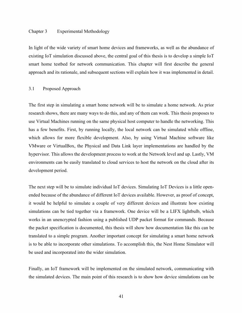
41
Chapter 3 Experimental Methodology
In light of the wide variety of smart home devices and frameworks, as well as the abundance of
existing IoT simulation discussed above, the central goal of this thesis is to develop a simple IoT
smart home testbed for network communication. This chapter will first describe the general
approach and its rationale, and subsequent sections will explain how it was implemented in detail.
3.1 Proposed Approach
The first step in simulating a smart home network will be to simulate a home network. As prior
research shows, there are many ways to do this, and any of them can work. This thesis proposes to
use Virtual Machines running on the same physical host computer to handle the networking. This
has a few benefits. First, by running locally, the local network can be simulated while offline,
which allows for more flexible development. Also, by using Virtual Machine software like
VMware or VirtualBox, the Physical and Data Link layer implementations are handled by the
hypervisor. This allows the development process to work at the Network level and up. Lastly, VM
environments can be easily translated to cloud services to host the network on the cloud after its
development period.
The next step will be to simulate individual IoT devices. Simulating IoT Devices is a little open-
ended because of the abundance of different IoT devices available. However, as proof of concept,
it would be helpful to simulate a couple of very different devices and illustrate how existing
simulations can be tied together via a framework. One device will be a LIFX lightbulb, which
works in an unencrypted fashion using a published UDP packet format for commands. Because
the packet specification is documented, this thesis will show how documentation like this can be
translated to a simple program. Another important concept for simulating a smart home network
is to be able to incorporate other simulations. To accomplish this, the Nest Home Simulator will
be used and incorporated into the wider simulation.
Finally, an IoT framework will be implemented on the simulated network, communicating with
the simulated devices. The main point of this research is to show how device simulations can be
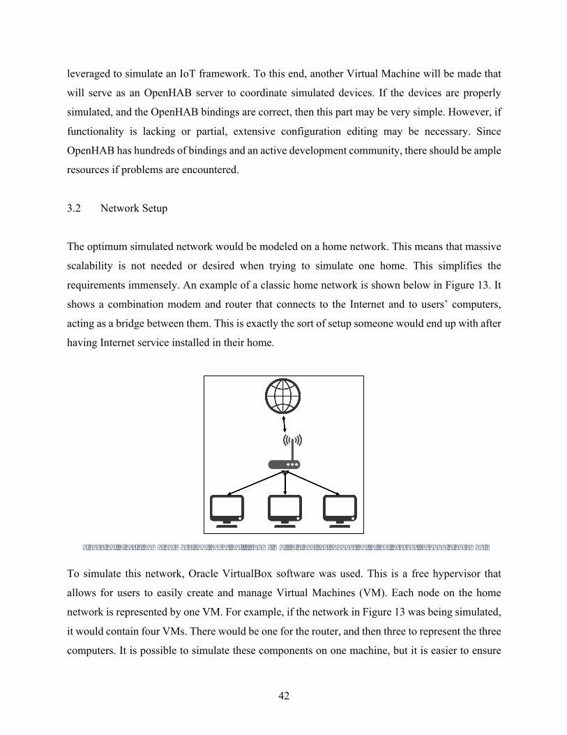
42
leveraged to simulate an IoT framework. To this end, another Virtual Machine will be made that
will serve as an OpenHAB server to coordinate simulated devices. If the devices are properly
simulated, and the OpenHAB bindings are correct, then this part may be very simple. However, if
functionality is lacking or partial, extensive configuration editing may be necessary. Since
OpenHAB has hundreds of bindings and an active development community, there should be ample
resources if problems are encountered.
3.2 Network Setup
The optimum simulated network would be modeled on a home network. This means that massive
scalability is not needed or desired when trying to simulate one home. This simplifies the
requirements immensely. An example of a classic home network is shown below in Figure 13. It
shows a combination modem and router that connects to the Internet and to users’ computers,
acting as a bridge between them. This is exactly the sort of setup someone would end up with after
having Internet service installed in their home.
Figure13.Classichomenetworkconfiguration.ItshowsmultipledevicesconnectingtotheInternetthroughagateway.
To simulate this network, Oracle VirtualBox software was used. This is a free hypervisor that
allows for users to easily create and manage Virtual Machines (VM). Each node on the home
network is represented by one VM. For example, if the network in Figure 13 was being simulated,
it would contain four VMs. There would be one for the router, and then three to represent the three
computers. It is possible to simulate these components on one machine, but it is easier to ensure
43
complete control of their communication by making separate VMs with closely-controlled
communication. VirtualBox makes it easy to manage multiple VMs, making a list of all configured
options as shown in Figure 14. Each VM can be turned on/off independently, and VirtualBox will
also support helpful features like copy and paste across VMs.
Figure14.VirtualBoxVMManager.ItshowsalistofallconfiguredVMsontheleft,andcorrespondingsystemdetailsonthe
right.
Each of the VMs uses Ubuntu 16.04.2 LTS as its Operating System. This Operating System was
selected for a number of reasons. First, it is one of the most common Linux distributions in use,
which makes it easier to find support if needed. It is also a Debian-based Operating System, which
essentially guarantees that applications made for Debian will work on Ubuntu. Also, Linux allows
for finer control of some underlying network settings that makes setup easier than it would be in
windows. The machines were given 10 GB of hard drive space, much of which is used by the
Operating System itself. Also, they were given 512-1024 MB of Virtual RAM. Some space could
have been saved by allowing the machines to expand as needed, but this does impact performance
adversely.

44
VirtualBox allows for each VM to have up the four virtual Ethernet adapters connected to it [51].
A virtual Ethernet adapter is exactly what it sounds like, it allows the Operating System to
recognize and use a specified adapter. Further, when activating an adapter, one can name a
common channel on which the adapter can communicate. This is shown in Figure 15 below. This
menu is accessed by selecting the “Settings” option for a VM. In this case, the LIFX_Bulb VM is
selected, and Ethernet adapter 2 has been enabled. The common channel that this connects to is
labeled ‘intnet’. To communicate directly between two VM’s, they must both have an adapter
enabled and linked to the same common channel. In this case, the LIFX-Bulb and Router VMs
both must have an adapter connected to ‘intnet’.
Figure15.VirtualBoxNetworkSettings.ShowsanenabledNetworkAdapterconnectedtothecommonchannel‘intnet.’
Ideally, one would want each end node to have exactly one Ethernet adapter enabled, and
connected to its own common channel with the router. This means that the router would have
multiple Ethernet adapters enabled, each with a dedicated connection to a node. This is impractical.
As Figure 15 shows, the router would only be able to have four such dedicated connections, one
of which is reserved for the Internet connection. To address this, multiple Router VMs could have
been made and set up in a tree-like forwarding scheme, but this is impractical. Instead, it is
configured so all devices share a common channel with the Router VM, and packet forwarding
rules are used to force end nodes to communicate through the router. While devices could

45
physically communicate even with the Router VM turned off, these rules prevent them from doing
so and thus maintain the integrity of the network simulation.
This made every node physically able to communicate, but there still needed to be network
configurations within Ubuntu itself. For this setup, a guide by Brian Linkletter was used [51]. The
first step was to launch a VM and edit its network interfaces file as shown in Figure 16. The
Ethernet adapter for this VM is identified by ‘enp0s8’, and the ‘auto’ line indicates that it should
start up at boot. It then shows the device being set up with a static IP address. A home network
would more commonly used automatic address assignment via DHCP, but static makes
development easier and it would not be difficult to transition this to DHCP. Every VM is
configured similar to this with a different IP address.
Figure16.NetworkinterfacesconfigurationforsimulatedIoTdevices.ItshowsstaticIPassignmentandDNSsetup.
Routing information can also be set up in this interfaces file, but it worked inconsistently. To
remedy this, a simple script was made that runs at startup and manually adds a default gateway to
the VM. This, combined with DNS service, allows for routing of messages through the Router
VM. The Router VM is a little different to account for having more than one Ethernet interface
present. Like the others, it has a static IP address for the simulated internal network. However, it
does use DHCP to get an IP address for its outward-facing Ethernet interface. It also makes use of
a configuration script to perform routing, which adds forwarding between the two interfaces to the
routing table.
The final network topology looks something like Figure 17 below. The Router VM connects to the
Host computer, and ultimately its Internet connection, via DHCP. The remaining components all
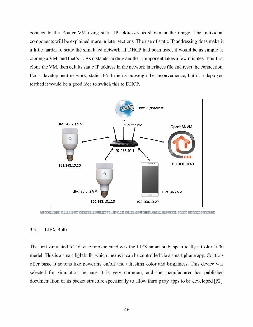
46
connect to the Router VM using static IP addresses as shown in the image. The individual
components will be explained more in later sections. The use of static IP addressing does make it
a little harder to scale the simulated network. If DHCP had been used, it would be as simple as
cloning a VM, and that’s it. As it stands, adding another component takes a few minutes. You first
clone the VM, then edit its static IP address in the network interfaces file and reset the connection.
For a development network, static IP’s benefits outweigh the inconvenience, but in a deployed
testbed it would be a good idea to switch this to DHCP.
Figure17.Simulatednetworktopology.Itshowstwosimulatedbulbs,acontrollerandanOpenHABhubconnected.
3.3 LIFX Bulb
The first simulated IoT device implemented was the LIFX smart bulb, specifically a Color 1000
model. This is a smart lightbulb, which means it can be controlled via a smart phone app. Controls
offer basic functions like powering on/off and adjusting color and brightness. This device was
selected for simulation because it is very common, and the manufacturer has published
documentation of its packet structure specifically to allow third party apps to be developed [52].

47
This seemed like a prime candidate for simulation because there are many apps that people have
made to control the device, but all have required physical bulbs for testing.
3.3.1 LIFX LAN Protocol
LIFX light bulbs are Wi-Fi based LED smart lightbulbs [52]. As such, they connect directly to a
home network without using a hub to convert between ZigBee/Z-Wave and IP connections. Their
operation has a few key components. First, for initial setup they utilize an AllJoyn-like scheme
where the bulb acts as a Wi-Fi hotspot, and the user connects to the bulb directly via a phone app.
Credentials for the home wireless network are then sent from the phone to the bulb, and it connects
to the home network. Once it is on the home network, applications can interact with the bulb via
either a LAN or cloud connection.
The smart phone app provided by LIFX interacts primarily via their cloud service. This uses a
RESTful interface, and has required token authentication as well as TLS encryption [52].
However, there are a couple factors that make this a less-desirable candidate for simulation. First,
despite the availability of the API, most frameworks that have added LIFX support do so only on
a local network. This is primarily because the frameworks already have home network access via
some other means in most cases, so there is no need to involve another cloud service into the mix.
More importantly, LIFX has intentionally withheld needed information from the specification to
prevent accurate simulation of bulbs using the cloud API. When asked about the prospect of
writing an emulator, they replied “You might be able to emulate a device to your own app, or other
developers apps built using the public API but we haven't released enough information to convince
our official apps that your emulator is a real device.” [53] These factors make it a less-attractive
candidate for simulation.
Most other frameworks interact with LIFX bulbs using its LAN Protocol. This essentially defines
an application layer protocol on top of UDP packets. There is no authentication or encryption, as
this option is only designed to be used on a home network internally. This is also the preferred
method for third party frameworks to interact with LIFX, this is especially true for hub-based
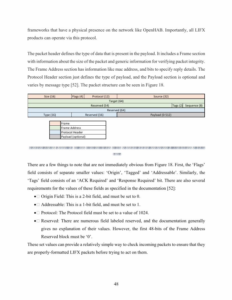
48
frameworks that have a physical presence on the network like OpenHAB. Importantly, all LIFX
products can operate via this protocol.
The packet header defines the type of data that is present in the payload. It includes a Frame section
with information about the size of the packet and generic information for verifying packet integrity.
The Frame Address section has information like mac address, and bits to specify reply details. The
Protocol Header section just defines the type of payload, and the Payload section is optional and
varies by message type [52]. The packet structure can be seen in Figure 18.
Figure18.LIFXLANHeaderformat.ShowssectionsforFrame,FrameAddress,ProtocolandPayload.Allsizesareshowninbits
[52].
There are a few things to note that are not immediately obvious from Figure 18. First, the ‘Flags’
field consists of separate smaller values: ‘Origin’, ‘Tagged’ and ‘Addressable’. Similarly, the
‘Tags’ field consists of an ‘ACK Required’ and ‘Response Required’ bit. There are also several
requirements for the values of these fields as specified in the documentation [52]:
• Origin Field: This is a 2-bit field, and must be set to 0.
• Addressable: This is a 1-bit field, and must be set to 1.
• Protocol: The Protocol field must be set to a value of 1024.
• Reserved: There are numerous field labeled reserved, and the documentation generally
gives no explanation of their values. However, the first 48-bits of the Frame Address
Reserved block must be ‘0’.
These set values can provide a relatively simple way to check incoming packets to ensure that they
are properly-formatted LIFX packets before trying to act on them.
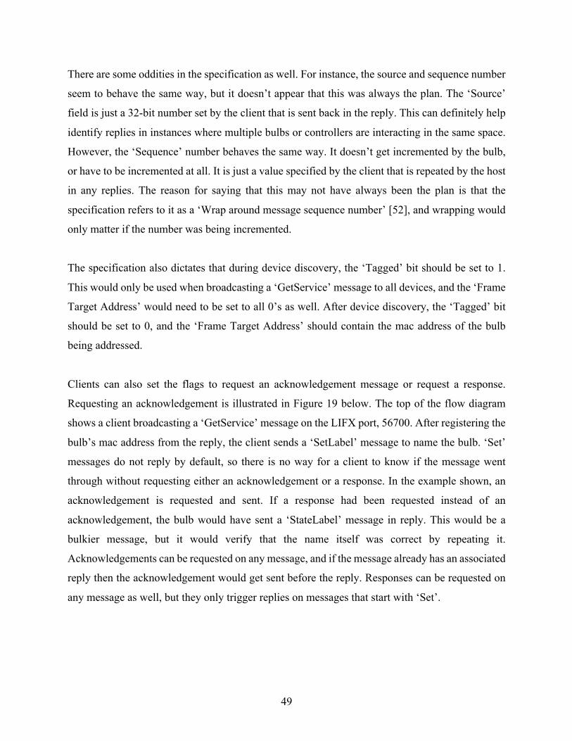
49
There are some oddities in the specification as well. For instance, the source and sequence number
seem to behave the same way, but it doesn’t appear that this was always the plan. The ‘Source’
field is just a 32-bit number set by the client that is sent back in the reply. This can definitely help
identify replies in instances where multiple bulbs or controllers are interacting in the same space.
However, the ‘Sequence’ number behaves the same way. It doesn’t get incremented by the bulb,
or have to be incremented at all. It is just a value specified by the client that is repeated by the host
in any replies. The reason for saying that this may not have always been the plan is that the
specification refers to it as a ‘Wrap around message sequence number’ [52], and wrapping would
only matter if the number was being incremented.
The specification also dictates that during device discovery, the ‘Tagged’ bit should be set to 1.
This would only be used when broadcasting a ‘GetService’ message to all devices, and the ‘Frame
Target Address’ would need to be set to all 0’s as well. After device discovery, the ‘Tagged’ bit
should be set to 0, and the ‘Frame Target Address’ should contain the mac address of the bulb
being addressed.
Clients can also set the flags to request an acknowledgement message or request a response.
Requesting an acknowledgement is illustrated in Figure 19 below. The top of the flow diagram
shows a client broadcasting a ‘GetService’ message on the LIFX port, 56700. After registering the
bulb’s mac address from the reply, the client sends a ‘SetLabel’ message to name the bulb. ‘Set’
messages do not reply by default, so there is no way for a client to know if the message went
through without requesting either an acknowledgement or a response. In the example shown, an
acknowledgement is requested and sent. If a response had been requested instead of an
acknowledgement, the bulb would have sent a ‘StateLabel’ message in reply. This would be a
bulkier message, but it would verify that the name itself was correct by repeating it.
Acknowledgements can be requested on any message, and if the message already has an associated
reply then the acknowledgement would get sent before the reply. Responses can be requested on
any message as well, but they only trigger replies on messages that start with ‘Set’.
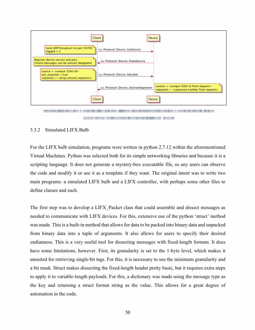
50
Figure19.LIFXLANcommunicationflowdiagram.Itshowsdevicediscoveryandacommandbeingsentwithan
acknowledgementrequested.CourtesyofLifiLabsÓ2017.
3.3.2 Simulated LIFX Bulb
For the LIFX bulb simulation, programs were written in python 2.7.12 within the aforementioned
Virtual Machines. Python was selected both for its simple networking libraries and because it is a
scripting language. It does not generate a mystery-box executable file, so any users can observe
the code and modify it or use it as a template if they want. The original intent was to write two
main programs: a simulated LIFX bulb and a LIFX controller, with perhaps some other files to
define classes and such.
The first step was to develop a LIFX_Packet class that could assemble and dissect messages as
needed to communicate with LIFX devices. For this, extensive use of the python ‘struct’ method
was made. This is a built-in method that allows for data to be packed into binary data and unpacked
from binary data into a tuple of arguments. It also allows for users to specify their desired
endianness. This is a very useful tool for dissecting messages with fixed-length formats. It does
have some limitations, however. First, its granularity is set to the 1-byte level, which makes it
unsuited for retrieving single-bit tags. For this, it is necessary to use the minimum granularity and
a bit mask. Struct makes dissecting the fixed-length header pretty basic, but it requires extra steps
to apply it to variable-length payloads. For this, a dictionary was made using the message type as
the key and returning a struct format string as the value. This allows for a great degree of
automation in the code.

51
Also made was a LIFX_Bulb class to actually receive and interpret actions. The attributes of this
class were derived by determining all fields that are ever set or retrieved from the bulb. This
includes things like current light level, color, firmware, etc. For fields like firmware or Wi-Fi signal
strength, values were preset based on observations from packet sniffing an actual LIFX bulb’s web
traffic. The main function of the LIFX_Bulb class was to interpret messages. To do this, it first
checked that packets were valid, then used conditional statements to build a list of reply packets
to be sent. The list was implemented because different messages can sometimes require up to three
packets in reply. This class was instantiated in a listener program that handled the visual and
network elements of the simulation.
The bulb_sim.py program used the aforementioned classes to provide a visual simulation that
shows users real-time traffic as well as a view of how the bulb behaves to commands. At its core
is a simple UDP server program that listens on port 56700 and responds the packets as they come
in. It binds to a socket, which allows for messages to queue if it is getting bombarded quickly. The
visual portion was done using pythons Tkinter library to build and update a display. Because the
socket listen method is blocking and Tkinter requires an infinite event loop, the socket listen
function is run in a separate thread.
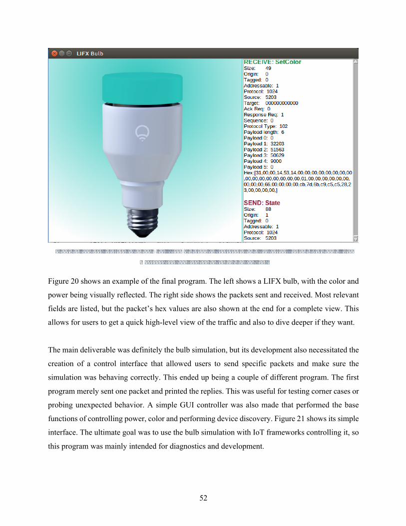
52
Figure20.Theuserinterfaceforbulb_sim.py.ItshowsagraphicalrepresentationofthecurrentlightbulbstateandallLIFX
messagessentandreceivedbythebulbontheright.
Figure 20 shows an example of the final program. The left shows a LIFX bulb, with the color and
power being visually reflected. The right side shows the packets sent and received. Most relevant
fields are listed, but the packet’s hex values are also shown at the end for a complete view. This
allows for users to get a quick high-level view of the traffic and also to dive deeper if they want.
The main deliverable was definitely the bulb simulation, but its development also necessitated the
creation of a control interface that allowed users to send specific packets and make sure the
simulation was behaving correctly. This ended up being a couple of different program. The first
program merely sent one packet and printed the replies. This was useful for testing corner cases or
probing unexpected behavior. A simple GUI controller was also made that performed the base
functions of controlling power, color and performing device discovery. Figure 21 shows its simple
interface. The ultimate goal was to use the bulb simulation with IoT frameworks controlling it, so
this program was mainly intended for diagnostics and development.
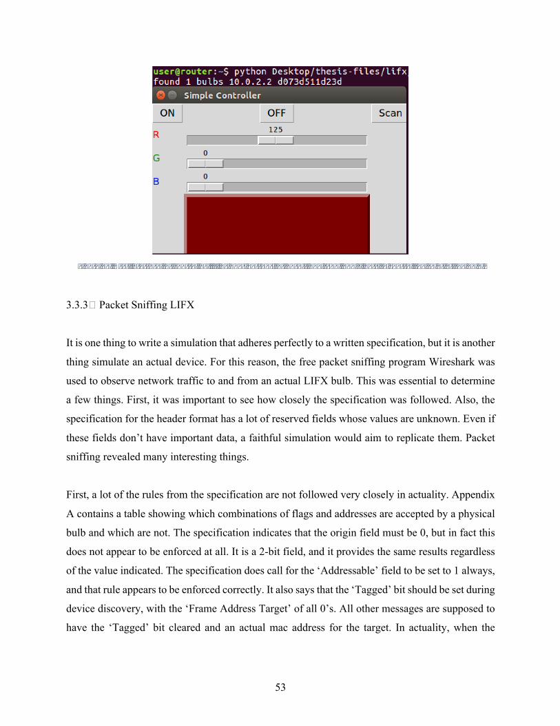
53
Figure21.Userinterfaceforcontrol.py.Itincludesbuttonsforon/offandscan,andsliderstocontrolthecolorofthebulb.
3.3.3 Packet Sniffing LIFX
It is one thing to write a simulation that adheres perfectly to a written specification, but it is another
thing simulate an actual device. For this reason, the free packet sniffing program Wireshark was
used to observe network traffic to and from an actual LIFX bulb. This was essential to determine
a few things. First, it was important to see how closely the specification was followed. Also, the
specification for the header format has a lot of reserved fields whose values are unknown. Even if
these fields don’t have important data, a faithful simulation would aim to replicate them. Packet
sniffing revealed many interesting things.
First, a lot of the rules from the specification are not followed very closely in actuality. Appendix
A contains a table showing which combinations of flags and addresses are accepted by a physical
bulb and which are not. The specification indicates that the origin field must be 0, but in fact this
does not appear to be enforced at all. It is a 2-bit field, and it provides the same results regardless
of the value indicated. The specification does call for the ‘Addressable’ field to be set to 1 always,
and that rule appears to be enforced correctly. It also says that the ‘Tagged’ bit should be set during
device discovery, with the ‘Frame Address Target’ of all 0’s. All other messages are supposed to
have the ‘Tagged’ bit cleared and an actual mac address for the target. In actuality, when the
54
‘Tagged’ bit is cleared, either an actual mac address or all 0’s will work. Lastly, the first ‘Reserved’
field is supposed to be all 0’s, but is actually the ascii values for ‘LIFXv2’.
Aside from the direct contradictions described above, there were a number of unexpected things
observed. First, any ‘GetService’ message will return two ‘StateService’ messages instead of the
one expected. The first is a message indicating that the bulb supports service 1, which corresponds
to UDP according to the documentation [52]. The second message indicates support for service 5,
which is not in the documentation at all. It is unclear what this refers to, as all communication
appears to be UDP.
There are also some message types that are not documented at all. Appendix B shows all supported
message types and their parameters. However, if one packet captures for an extended period of
time, they will start getting messages with type 111 and 406. These do not correspond to anything
in the documentation. Every 10-11 minutes, without any outside prompt, these messages will be
broadcast by the LIFX bulb as part of an unusual sequence. First, the bulb will transmit an
‘EchoResponse’, which shouldn’t be possible without first receiving an ‘EchoRequest’. The
payload includes the label of the bulb in addition to other data and the rest is zero-filled. It will
then send a ‘State’ message, with information like the current light level and color. Then mystery-
message 111 with a 2-byte payload that can change but doesn’t have to. It then sends a
‘StateHostInfo’ and a ‘StateWifiInfo’ message. Finally, it sends the other mystery-message, 406.
It has a 4-byte payload of ‘\xbc\x02\x00\x00’, but there is no way to know if that is just the one
physical bulb under observation or all bulbs. A printout of the captured data can be seen in
Appendix C. The sequence, aside from starting with an echo reply, contains all the information
one would need to configure a LIFX connection. Ten minutes is a pretty big window if the purpose
is to facilitate discovery. LIFX themselves are keeping quiet about the point of these messages,
the official reply from LIFX when someone asked about the messages in the development forums
was that they should ignore the messages [54].
Lastly, there are also some messages from the bulb that are not UDP messages from port 56700.
Specifically, every five seconds the bulb sends out mDNS broadcasts messages with AllJoyn
configuration information. This was unexpected, as nothing in the LIFX documentation suggests

55
that it adheres to AllJoyn standards. That said, the system of using the bulb as hotspot during initial
configuration matches the AllJoyn onboarding process. A Wireshark packet capture showing these
messages can be seen in Appendix D.
This captured data reflects the actual device communications, so in every instance where the
specification and the observed data conflicted, the observed data was mimicked in the simulation.
This meant considerably modifying the existing programs to send additional messages and to
check packet validity differently.
3.4 Nest Thermostat
The Nest Thermostat is a very popular take on the idea of smart HVAC controls. It allows for users
to set rules that may vary based on a number of circumstances. For instance, a user may set the
thermostat to detect when they are out of the house and relax the target temperature during that
time to save energy and money. That same user can also set a rule that says they return home every
day at 5:30, and the thermostat will then start preparing for their arrival before their return. The
following sections will discuss the underlying framework on which Nest systems work, as well as
Nest’s own approach to simulating devices.
3.4.1 Thread and Nest Weave Fabric
In addition to thermostats, Nest has a number of other products such as IP cameras and smoke
detectors. These products, and more, connect to each other and the Internet via a protocol called
Thread. Thread is a IPv6-based protocol that was specifically designed with the needs of the smart
home in mind [55]. It is a mesh network, designed to support roughly 250 connected nodes. It has
a few features that distinguish it from other mesh solutions like ZigBee and Z-Wave. First, it
leverages the pervasiveness of smart phone technology when admitting new nodes to the network.
The process to commission a new device on the network involves the prospective node getting a
temporary PIN from the user’s cell phone, which essentially makes users responsible for
controlling which devices are able to join [55]. This is very different from most other mesh network

56
approaches, which generally automate the discovery and commissioning process to a greater
extent.
The Thread mesh network itself is visualized in Figure 22. First, the bottom shows both the cloud
and smart phone connection to the Wi-Fi router, which is in turn connected to the border routers.
At this point, the network starts to resemble a classic mesh network topology, consisting of routers
and end devices. As the name suggests, routers are there to forward packets. Most end devices are
capable of being routers if needed, but power constraints may limit this. There is also one
designated Leader, which is primarily responsible for determining when things like if a new node
should be admitted as a router or not [55].
Figure22.ThreadNetworkTopology.Itshowsaphoneandcloudconnectingviaaborderrouter,thenaclassmeshnetwork
structurefortheinternalnetwork[56].CourtesyoftheThreadGroupÓ2015
57
There are a couple important takeaways from the structure of a Thread network. First, it supports
an arbitrary number of border routers, which allows for redundancy in getting off network. Also,
all routers maintain state with each other and the leader. This means that all optimum routes are
known by all routers, and that any router can replace the leader if it goes down. This provides
further redundancy and also avoids network flooding, which is a common way to route mesh
networks.
One of the primary goals of the Thread Group has been to make it as user-friendly as possible. A
large part of that comes from ensuring interoperability of components before users get their hands
on them. To this end, the Thread Group requires that devices get validated by a third-party lab
before they will certify it. They do provide a test harness to facilitate the development process
[55], but it is still among the more aggressive certification processes looked at in this thesis.
The Thread protocol stack is illustrated in Figure 23. As it shows, Thread is built on 802.15.4 lower
layers, and 6LoWPAN for the Network Layer. It also uses UDP as its primary Transport protocol,
but security spans all the way up to the Application Layer. This is because of the aforementioned
commissioning process that gets the user involved in actively approving devices [56]. In terms of
other security, Thread has all of the low-level protections mandated by the 802.15.4 standard.
However, because it is IP-based, it has additional optional security protocols like IPsec, TLS or
SSL available. It’s also worth noting that devices would have their own application layer protocols
on top of Thread, so additional application-layer security can also be employed.
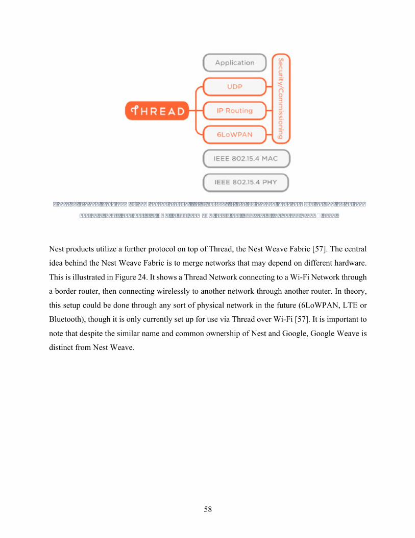
58
Figure23.ProtocolstackshowinghowThreadprotocolfitsin.ThreadfitsintotheprotocolstackbetweentheApplicationand
802.15.4Layers,andconsistofUDP,IPand6LoWPANlayers[56].CourtesyoftheThreadGroupÓ2015.
Nest products utilize a further protocol on top of Thread, the Nest Weave Fabric [57]. The central
idea behind the Nest Weave Fabric is to merge networks that may depend on different hardware.
This is illustrated in Figure 24. It shows a Thread Network connecting to a Wi-Fi Network through
a border router, then connecting wirelessly to another network through another router. In theory,
this setup could be done through any sort of physical network in the future (6LoWPAN, LTE or
Bluetooth), though it is only currently set up for use via Thread over Wi-Fi [57]. It is important to
note that despite the similar name and common ownership of Nest and Google, Google Weave is
distinct from Nest Weave.

59
Figure24.NestWeaveFabricDiagram.Itencompassesandbridgesnetworkswithdifferentunderlyinghardware[57].Courtesy
ofNestLabsÓ2017.
Nest relies on an encrypted cloud model; commands can only be sent to the thermostat through
Nest’s cloud API. The API is a JSON document, with the top level being broken down into
metadata, devices and structures [58]. A structure would be something like a home, in which there
would be multiple devices potentially. The cloud stores the intended state of various attributes,
and syncs with devices in a home. Various levels of permission are available, and must be
explicitly authorized when a device is admitted. All communication to and from the cloud are
encrypted [58]. This makes third-party network-accurate simulation of a Nest thermostat almost
impossible. One could mimic the behavior and the structure of the API itself, but the actual network
traffic would be different because encryption obscures the view of packet sniffing.
3.4.2 Nest Home Simulation
Though it would be extremely difficult for a third party to simulate a Nest thermostat, Nest
recognizes the value of an accurate simulation to product development. Nest facilitates third-party
application development by providing both a detailed API and a simulator that users can test their
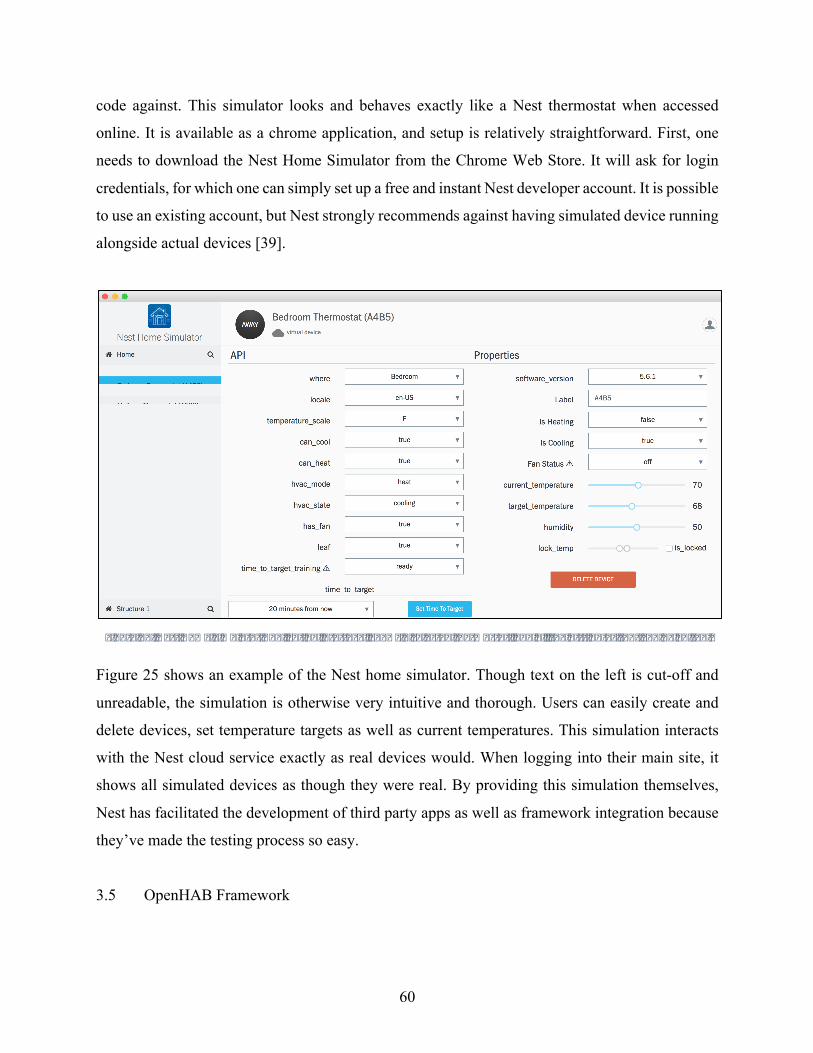
60
code against. This simulator looks and behaves exactly like a Nest thermostat when accessed
online. It is available as a chrome application, and setup is relatively straightforward. First, one
needs to download the Nest Home Simulator from the Chrome Web Store. It will ask for login
credentials, for which one can simply set up a free and instant Nest developer account. It is possible
to use an existing account, but Nest strongly recommends against having simulated device running
alongside actual devices [39].
Figure25.NestHomeSimulatorApplicationinterface.Showsaselectedthermostat,andalltheattributesthatcanbeedited.
Figure 25 shows an example of the Nest home simulator. Though text on the left is cut-off and
unreadable, the simulation is otherwise very intuitive and thorough. Users can easily create and
delete devices, set temperature targets as well as current temperatures. This simulation interacts
with the Nest cloud service exactly as real devices would. When logging into their main site, it
shows all simulated devices as though they were real. By providing this simulation themselves,
Nest has facilitated the development of third party apps as well as framework integration because
they’ve made the testing process so easy.
3.5 OpenHAB Framework

61
After implementing successful simulations that operate in isolation, the next goal became to
implement a framework on top of the simulated smart home devices to indirectly control them. As
discussed earlier, the landscape of IoT frameworks is already quite cluttered, so a means to test
and compare frameworks can be valuable for education and development of IoT communication
schemes. Simulating a home network is the first step towards that goal, simulating IoT devices is
the second, and simulating a third-party framework is the third. This section will discuss the
framework implementation.
For the third-party framework, OpenHAB was selected. This was done for a few reasons. First,
OpenHAB is hardware and vendor neutral, which makes a software-only virtual implementation
easier than it would be for systems that require specific hardware. Also, OpenHAB is designed to
run on a dedicated machine constantly in a home network. This fits the structure of the simulated
home network, where each physical device is represented by a VM. Lastly, OpenHAB has ready-
built Bindings for LIFX and Nest, which ideally fits the simulated devices.
To set up OpenHAB, the first step was to make another VM on the home network. This was done
by cloning the LIFX Bulb VM and assigning it a new IP address. This method was selected because
it was important that the OpenHAB hub have the same connection attributes as any other client on
the network. Once the VM was made, a few small changes had to be implemented. First, the current
version of the Java Runtime Environment (JRE) had to be installed. As stated earlier, OpenHAB
can run on any machine that is capable of running a Java Virtual Machine, so getting Java is
necessary for that.
With Java already installed and Ubuntu as the Operating System, OpenHAB 2.1 can be easily
installed using apt-get. One thing to note is that the OpenHAB service needs to be started when
the VM boots up, and this can be accomplished with a simple bash script to start the service.
3.5.1 LIFX Setup in OpenHAB
Because OpenHAB 2.1 includes an available LIFX Binding, this version was decided upon. As
discussed earlier, OpenHAB 2.0 and later provide GUI options for setting up devices via the

62
OpenHAB PaperUI user interface. This interface makes some parts of configuration very simple,
such as adding installing Bindings as shown in Figure 26. Installing the LIFX Binding was as
simple as selecting ‘Add-ons’, then finding ‘LIFX Binding’ on the list and clicking it to install.
Figure26.OpenHABPaperUIAdd-oninstallationscreen.
Once the binding is installed, OpenHAB knows the markers to look for when adding a new device.
To add a device, one need only select the ‘Inbox’ option and click the plus sign to add a device. It
then asks which installed Binding to use, and selecting ‘LIFX Binding’ causes it to show all found
bulbs. For this to work, the LIFX Bulb VM needs to be on with the bulb_sim.py program running.
If everything is set up correctly, it will show the found bulb and allow it to be added as shown
below in Figure 27.
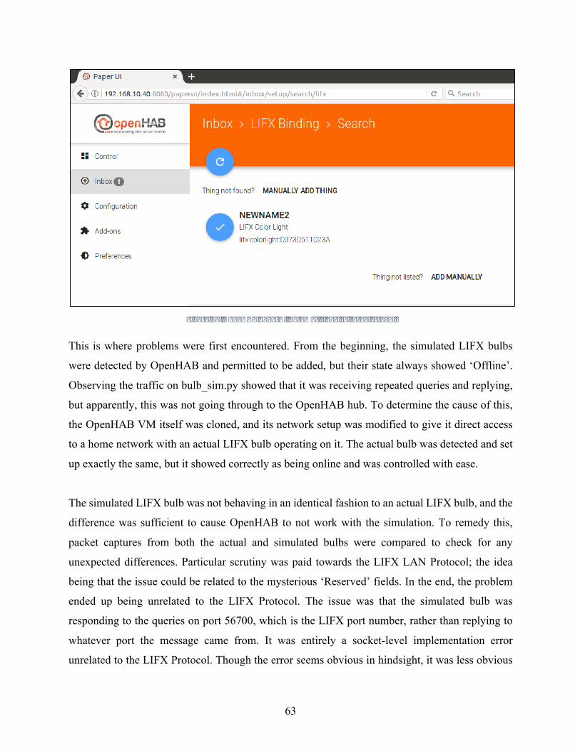
63
Figure27.OpenHABPaperUIautomaticdevicesetupscreen.
This is where problems were first encountered. From the beginning, the simulated LIFX bulbs
were detected by OpenHAB and permitted to be added, but their state always showed ‘Offline’.
Observing the traffic on bulb_sim.py showed that it was receiving repeated queries and replying,
but apparently, this was not going through to the OpenHAB hub. To determine the cause of this,
the OpenHAB VM itself was cloned, and its network setup was modified to give it direct access
to a home network with an actual LIFX bulb operating on it. The actual bulb was detected and set
up exactly the same, but it showed correctly as being online and was controlled with ease.
The simulated LIFX bulb was not behaving in an identical fashion to an actual LIFX bulb, and the
difference was sufficient to cause OpenHAB to not work with the simulation. To remedy this,
packet captures from both the actual and simulated bulbs were compared to check for any
unexpected differences. Particular scrutiny was paid towards the LIFX LAN Protocol; the idea
being that the issue could be related to the mysterious ‘Reserved’ fields. In the end, the problem
ended up being unrelated to the LIFX Protocol. The issue was that the simulated bulb was
responding to the queries on port 56700, which is the LIFX port number, rather than replying to
whatever port the message came from. It was entirely a socket-level implementation error
unrelated to the LIFX Protocol. Though the error seems obvious in hindsight, it was less obvious
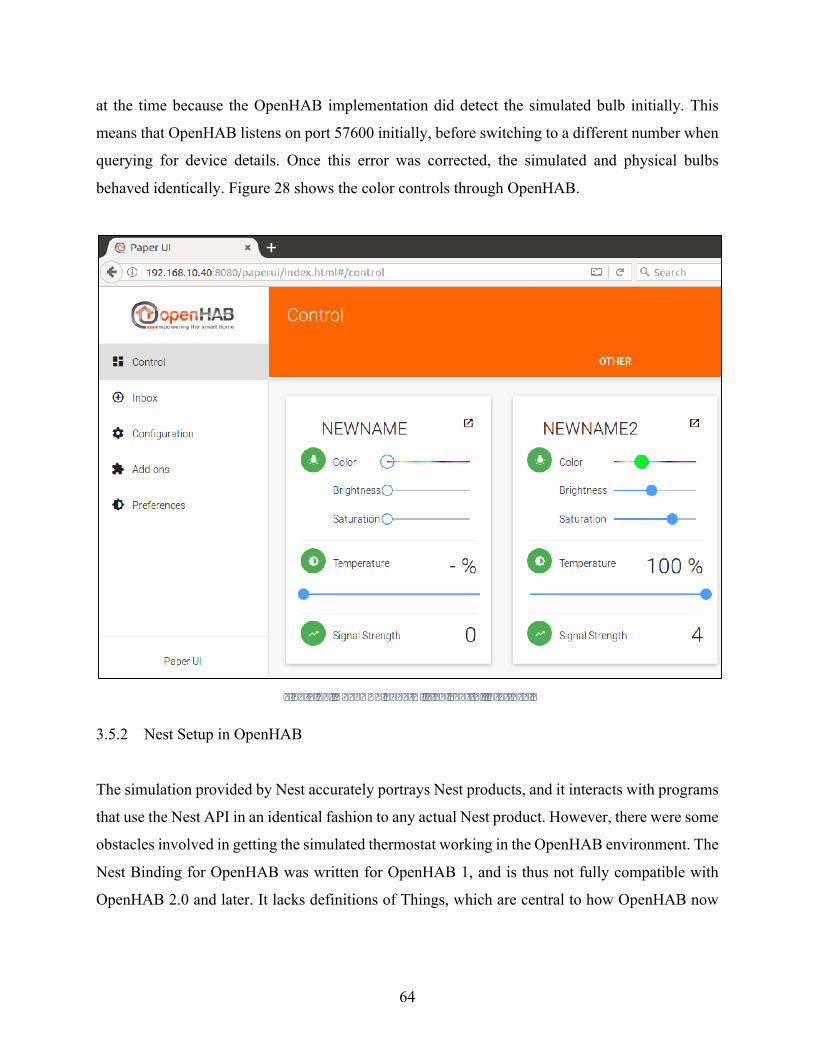
64
at the time because the OpenHAB implementation did detect the simulated bulb initially. This
means that OpenHAB listens on port 57600 initially, before switching to a different number when
querying for device details. Once this error was corrected, the simulated and physical bulbs
behaved identically. Figure 28 shows the color controls through OpenHAB.
Figure28.OpenHABPaperUILIFXcontrolinterface.
3.5.2 Nest Setup in OpenHAB
The simulation provided by Nest accurately portrays Nest products, and it interacts with programs
that use the Nest API in an identical fashion to any actual Nest product. However, there were some
obstacles involved in getting the simulated thermostat working in the OpenHAB environment. The
Nest Binding for OpenHAB was written for OpenHAB 1, and is thus not fully compatible with
OpenHAB 2.0 and later. It lacks definitions of Things, which are central to how OpenHAB now
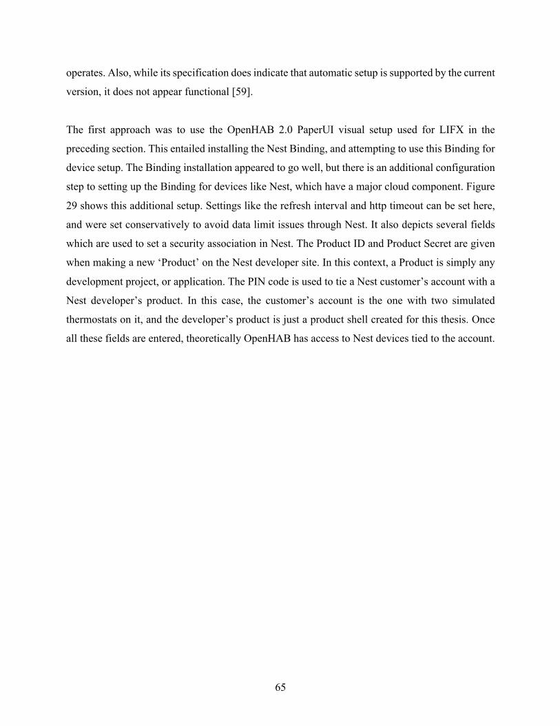
65
operates. Also, while its specification does indicate that automatic setup is supported by the current
version, it does not appear functional [59].
The first approach was to use the OpenHAB 2.0 PaperUI visual setup used for LIFX in the
preceding section. This entailed installing the Nest Binding, and attempting to use this Binding for
device setup. The Binding installation appeared to go well, but there is an additional configuration
step to setting up the Binding for devices like Nest, which have a major cloud component. Figure
29 shows this additional setup. Settings like the refresh interval and http timeout can be set here,
and were set conservatively to avoid data limit issues through Nest. It also depicts several fields
which are used to set a security association in Nest. The Product ID and Product Secret are given
when making a new ‘Product’ on the Nest developer site. In this context, a Product is simply any
development project, or application. The PIN code is used to tie a Nest customer’s account with a
Nest developer’s product. In this case, the customer’s account is the one with two simulated
thermostats on it, and the developer’s product is just a product shell created for this thesis. Once
all these fields are entered, theoretically OpenHAB has access to Nest devices tied to the account.

66
Figure29.OpenHABNestBindingconfigurationscreen.
Though this setup appeared to complete successfully, OpenHAB did not have access to the
simulated Nest thermostats. This is not an issue with the simulation, rather it is an issue of
compatibility between OpenHAB 2 and its Nest Binding that was written for OpenHAB 1. There
is a Nest Binding 2.0 in the works, but it has not yet been released [59].
To get any functionality through OpenHAB it was necessary to manually edit the configuration
files. This consists of a few steps. First, the security association described above needs to be
manually set up in the nest.cfg file, which essentially has all the same information from Figure 29
above, but in text form. Then the items need to be manually configured. This is done by creating
a nest.items file, in which individual Items are declared. Recall that an Item in OpenHAB is any
attribute that a user may want to read or write. In the case of a thermostat, there are many supported
attributes available in the Nest API. Lastly, the sitemap needs to be manually set up by creating a
nest.sitemap file. This allows for users to manually place buttons for things like on/off, or numbers
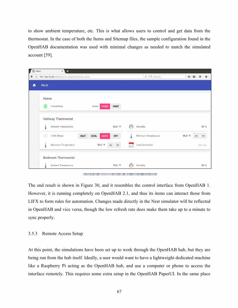
67
to show ambient temperature, etc. This is what allows users to control and get data from the
thermostat. In the case of both the Items and Sitemap files, the sample configuration found in the
OpenHAB documentation was used with minimal changes as needed to match the simulated
account [59].
Figure30.OpenHABBasicUINestcontrolinterface.
The end result is shown in Figure 30, and it resembles the control interface from OpenHAB 1.
However, it is running completely on OpenHAB 2.1, and thus its items can interact those from
LIFX to form rules for automation. Changes made directly in the Nest simulator will be reflected
in OpenHAB and vice versa, though the low refresh rate does make them take up to a minute to
sync properly.
3.5.3 Remote Access Setup
At this point, the simulations have been set up to work through the OpenHAB hub, but they are
being run from the hub itself. Ideally, a user would want to have a lightweight dedicated machine
like a Raspberry Pi acting as the OpenHAB hub, and use a computer or phone to access the
interface remotely. This requires some extra setup in the OpenHAB PaperUI. In the same place
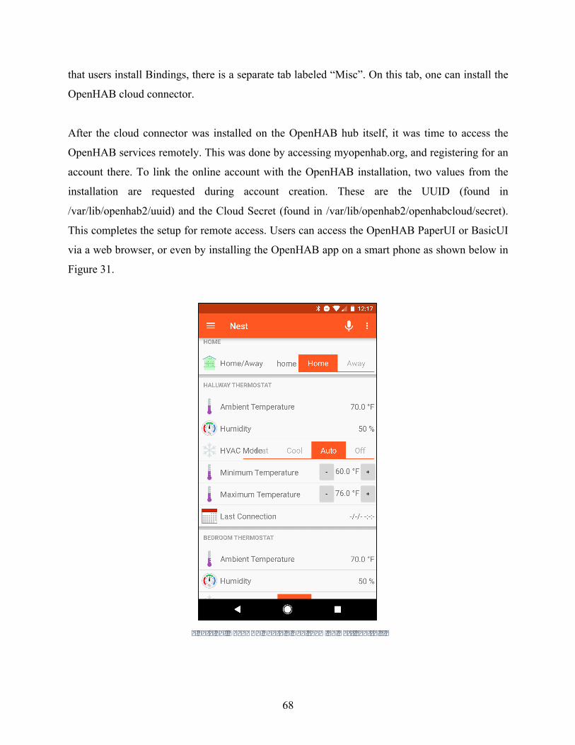
68
that users install Bindings, there is a separate tab labeled “Misc”. On this tab, one can install the
OpenHAB cloud connector.
After the cloud connector was installed on the OpenHAB hub itself, it was time to access the
OpenHAB services remotely. This was done by accessing myopenhab.org, and registering for an
account there. To link the online account with the OpenHAB installation, two values from the
installation are requested during account creation. These are the UUID (found in
/var/lib/openhab2/uuid) and the Cloud Secret (found in /var/lib/openhab2/openhabcloud/secret).
This completes the setup for remote access. Users can access the OpenHAB PaperUI or BasicUI
via a web browser, or even by installing the OpenHAB app on a smart phone as shown below in
Figure 31.
Figure31.OpenHABAndroidAppshowingNestcontrols.

69
Chapter 4 Testing and Validation
The ultimate goal of this thesis is to illustrate how simulating smart home devices, networks and
frameworks can serve as a tool towards future smart home development. This tool can be used for
educational purposes by showing how real-world devices respond to instructions at a network
traffic level. Or the tool can be used to test and develop new applications and frameworks with
existing devices. To achieve these goals, it is imperative that the simulated devices accurately
mimic their real-world counterparts. To test this, it was necessary to compare how the simulation
responded to various inputs with the way actual devices responded.
For the LIFX Bulb, validation was especially important because the simulated bulb was built from
scratch, rather than being provided by the manufacturer. As discussed earlier, the specification to
which the LIFX bulb was built proved to be incorrect in several ways. Some rules were not
enforced in the actual products, while other rules were outright violated. For this reason, the
simulated LIFX Bulb was modified heavily from the specified version to reflect actual network
traffic observed.
After gaining confidence that the simulated LIFX Bulb accurately mimicked the hardware, the
next step was to perform an automated series of tests on both the simulated bulb and the actual
bulb and compare responses. The resulting file, test_validity.py, sends every message type, with
every combination of flag settings in the protocol header. This was important because the
specification had already shown itself to be wrong about the role of many fields in the header. The
resulting test sent over 1300 commands, and dumped all replies into a text file for later comparison.
For this test, it is important to note that all messages contained valid headers. Figure 32 shows an
excerpt of the resulting text files side by side.
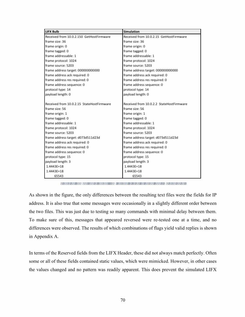
70
Figure32.Comparisonofoutputfromtest_validity.pyforactualandsimulatedbulbs.
As shown in the figure, the only differences between the resulting text files were the fields for IP
address. It is also true that some messages were occasionally in a slightly different order between
the two files. This was just due to testing so many commands with minimal delay between them.
To make sure of this, messages that appeared reversed were re-tested one at a time, and no
differences were observed. The results of which combinations of flags yield valid replies is shown
in Appendix A.
In terms of the Reserved fields from the LIFX Header, these did not always match perfectly. Often
some or all of these fields contained static values, which were mimicked. However, in other cases
the values changed and no pattern was readily apparent. This does prevent the simulated LIFX

71
Bulb from having 100% accuracy, but the LIFX developers have indicated in their forums that
these fields can be ignored.
Beyond testing valid traffic, efforts were also taken to determine how actual LIFX Bulbs responded
to invalid traffic. This testing was primarily done using the packet manipulation program Scapy to
craft packets that were similar to, but not identical to, correct packets. LIFX Bulbs did not respond
to packets that were too short or too long. Similarly, invalid commands yielded no response, and
messages to different port numbers were completely ignored. All of this functionality was built
into the simulation at well.
Packet testing aside, the simulated LIFX Bulb works not just with the controller developed
alongside it, but also with third-party controllers developed independent of this research. This is
shown by the full integration into OpenHAB, including local discovery. While it is impossible to
exhaustively test all possibilities, it appears safe to say that it is a reasonably-accurate network
simulation. This should not be construed to suggest that it is a complete emulation with identical
timing or anything similar, as its scope was limited specifically to network traffic content.
In terms of the Nest simulator, there is not an easy way for a third party to test the simulation
beyond simply using it. Since the developer of the simulation and the physical hardware are the
same group, and they claim it is accurate, that claim has to carry a lot of weight. The only testing
feasible is to set up both a simulated Nest thermostat and an actual one and determine if they
behave the same. This was done, and there was no noticeable difference in operation between the
two. This is exactly what one would expect because the Nest simulation goes through the same
Nest cloud servers that physical devices use.
Part of the point of this thesis was to show how simulations developed by others could be
incorporated into a testbed. When using other people’s simulations, one has to assume that they
are reasonably accurate until proven otherwise. One could compare them against hardware, but the
point of using simulations is ultimately to not use hardware. There would be little point to
simulating a device that is going to be purchased anyway.

72
Chapter 5 Using Developed Tools
This section will provide detailed instructions on how to make use of the tools developed as part
of this thesis. It will include a description of all needed files and steps to set up virtual
environments. Further, this section will also discuss how to develop additional simulated devices
to operate as part of this testbed. All programs and configuration files specified are available at
gitlab.com/jorgecomacho/thesis-files/.
5.1 Simulated Network Setup
As described earlier, there are many ways to make a simulated home network. If one is seeking to
simulate a smart home environment, a simple network like the one made for this research would
be a good choice. It is also possible to skip this step completely and simply run VMs on an actual
local network. This option is actually preferred if seeking to have both physical devices and
simulated devices operating together. Though there are many options for setting up a network, this
section will provide steps to make a basic home network like that used in this thesis.
1. Download and install a Virtual Machine hypervisor. Oracle’s VirtualBox is available at
https://www.virtualbox.org/wiki/Downloads. Other hypervisors like VMware Workstation
can be used, but their setup may vary significantly from these steps.
2. Download an Operating System image for the VMs. Ubuntu 16.04.2 LTS was used for this
thesis, and it is available for download at https://www.ubuntu.com/download/desktop. As
in step 1, another OS may be used, but sticking with a Debian Linux OS like Ubuntu is
recommended for compatibility.
3. Launch VirtualBox, and click the ‘new’ option to create a new VM. This will be the Router
VM, so name it accordingly. Ensure that the ‘Type’ is set to ‘Linux’ and the ‘Version’
matches the downloaded OS, in this case it would be ‘Ubuntu (64-bit)’. Leaving default
settings for the rest of the configuration is fine.
4. Select the Router VM on the VM Manager screen, then click the ‘Settings’ option. Select
the ‘Storage’ tab, then select the field under the IDE Controller that shows ‘Empty’ as
shown in Figure 33. Click the disk icon off to the right, and select the OS image that was

73
downloaded in Step 2. This will effectively mount the OS image and allow for a Linux
installation when the VM is turned on.
Figure33.VirtualBoxSettingsshowingmountingofUbuntuimage.
5. Select the ‘Start’ option to turn on the VM. Follow along with the Ubuntu installation
wizard, using default settings when unsure. Once the Ubuntu desktop is shown after
installation, turn off the VM.
6. Right-click the Router VM, and select the clone option. This will be an IoT device VM, so
name it according to the device it will represent, ‘LIFX Bulb’ for example. Ensure that the
box to reinitialize MAC address is checked as shown in Figure 34. Also, set it up as a Full
Clone rather than a Linked Clone.
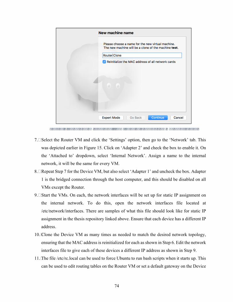
74
Figure34.VirtualBoxCloneVMscreensetup.ItshowstheoptiontogenerateanewMACaddressselected.
7. Select the Router VM and click the ‘Settings’ option, then go to the ‘Network’ tab. This
was depicted earlier in Figure 15. Click on ‘Adapter 2’ and check the box to enable it. On
the ‘Attached to’ dropdown, select ‘Internal Network’. Assign a name to the internal
network, it will be the same for every VM.
8. Repeat Step 7 for the Device VM, but also select ‘Adapter 1’ and uncheck the box. Adapter
1 is the bridged connection through the host computer, and this should be disabled on all
VMs except the Router.
9. Start the VMs. On each, the network interfaces will be set up for static IP assignment on
the internal network. To do this, open the network interfaces file located at
/etc/network/interfaces. There are samples of what this file should look like for static IP
assignment in the thesis repository linked above. Ensure that each device has a different IP
address.
10. Clone the Device VM as many times as needed to match the desired network topology,
ensuring that the MAC address is reinitialized for each as shown in Step 6. Edit the network
interfaces file to give each of these devices a different IP address as shown in Step 9.
11. The file /etc/rc.local can be used to force Ubuntu to run bash scripts when it starts up. This
can be used to edit routing tables on the Router VM or set a default gateway on the Device
75
VMs. Samples of both approaches can be found in the repository, and they should be copied
to the VMs.
The above steps will suffice for making a very basic home network simulation. Additional features
like DNS, DHCP, and a Firewall can be added to make this a more robust network simulation, but
the steps above are sufficient for a basic home network.
5.2 LIFX Simulation Setup
As shown in the thesis git repository, there are several python programs associated with the LIFX
simulation. All files are written in Python 2.7. Some of these are for testing, while others are
essential for the operation of the simulation. This section will go over the steps needed to ensure
that the VM can run the programs, then each of the program’s purpose and use will be explained
briefly.
1. Ensure python 2 is installed. Open a terminal in the Device VM and type ‘python –V’. This
will display the currently-installed version of python. If it starts with ‘Python 2.7.’ it should
be fine. If not, install Python 2 from python.org.
2. Install Tkinter, which is a GUI library for python and necessary in a couple LIFX programs
included in the thesis repository. Open a terminal and type ‘sudo apt-get install python-tk’.
3. Install python package manager ‘pip’. Open a terminal and type ‘sudo apt-get install
python-pip’. It is already installed in most cases, but this will ensure that is the case.
4. Install PIL, which is used in conjunction with Tkinter for displaying and formatting images
in a GUI. Open a terminal and type ‘pip install Pillow’.
5. Ensure that the LIFX class declaration files, lifx_packet.py and lifx_bulb.py, are installed
in the same directory as the other LIFX files from the git repository.
The above steps will be sufficient to get all prerequisites for the LIFX python files to run. Because
there are a number of files, a brief description of each will be provided below.

76
• Lifx_packet.py: This file defines a class to handle assemble and interpret messages
transmitted in the LIFX LAN protocol format. It contains functions to unpack a message
into its component parts and to assemble components into a byte string for transfer.
• Lifx_bulb.py: This file defines a class to represent an instance of a LIFX Bulb. It has
attributes that would be found on an actual bulb, such as firmware version, color and power
status. It is responsible for determining the appropriate action after receiving instructions.
• Bulb_sim.py: This is the primary program that would be run by the user to simulate a LIFX
bulb. It provides a GUI to show the current state of the bulb as well as a summary of traffic
to and from the Bulb. It handles the simulated bulb’s network communication.
• Control.py: This is a simple GUI controller that allows for users to scan a network for LIFX
Bulbs, turn them off/on and adjust their color.
• Test_receive.py: This is a simple program that sends one command to a LIFX Bulb and
prints out its reply. It is used to test individual cases or further probe unexpected actions.
The command sent needs to be edited in the source file.
• Test_validity.py: This program performs a battery of tests by sending every LIFX
command with every combination of header flags, and putting the results in a text file. It
is designed to be run against a physical bulb and a simulated bulb to ensure the same
responses.
• Listener.py: This program passively listens on the LIFX port of 56700 and prints out
packets that are observed. It is used to observe packets that are sent by bulbs without any
outside prompt.
5.3 Nest Home Simulator Setup
Setting up the home simulator from Nest requires only a few steps. This section will provide step-
by-step instructions for getting set up.
1. Download the Nest Home Simulator from the Chrome Store. It is available at
‘https://chrome.google.com/webstore/detail/nest-home-
simulator/jmcapoebgeaabepohkchkldlfhchkega’.

77
2. Go to ‘nest.com’ and register for a new account. This will be effectively the same as a
customer’s account, but do not use the same account as one with nest hardware associated
with it.
3. Launch the Nest Home Simulator that was downloaded in Step 1, log in with the credentials
made in Step 2.
4. Select the ‘Home’ structure on the left of the screen, and click ‘Add Thermostat’ in the
upper right to add two thermostats. More can be added, but these steps will mirror the
experimental setup of this thesis. Use the ‘where’ dropdown to set one to ‘Bedroom’ and
the other to ‘Hallway’, and clear the ‘Label’ field for both.
5. Go to ‘developers.nest.com’, log in or create a new account, and click the option to ‘Create
a new Product’. This ‘product’ refers to the nest integration with an application, in this case
the application will be OpenHAB. Figure 35 shows an example of the product creation
screen. A unique name must be chosen, along with a brief description. Support URL is
required but not tested, the home page for an academic institution is sufficient. The ‘Default
OAuth Redirect’ field should be left blank to allow for manually pairing accounts using a
PIN. This is also the stage when one selects the required permissions. At a minimum,
reading and writing the thermostat should be selected.
Figure35.NestDevelopersnewproductsetupform,showingbasicconfiguration.

78
6. A new screen will appear with some product numbers, these will be important for
integrating with OpenHAB in the next section, so make note of them. An Example of this
screen is shown below in Figure 36.
Figure36. NestDeveloperProductSecurityAssociationinformation.Asprovidedafterproductcreation.
7. Open a web browser and navigate to the Authorization URL that was issued in Step 6. Log
in with the account created in Step 2. A screen similar to Figure 37 will be shown asking
for permissions. Agree to this, and a PIN will be displayed on screen. Make note of this, as
it will be needed for OpenHAB integration.
Figure37.NestPermissionswindowduringsetup.ItappearswhenauthorizingtheNestdeveloperproducttoaccess
theNestaccount.

79
5.4 OpenHAB Setup
This section will walk through the initial installation of OpenHAB itself on a VM. The setup of
OpenHAB with the simulated devices is explained in some detail in Chapter 4 of this thesis. Much
of the installation procedure below is taken from OpenHAB’s documentation [35].
1. Create a new VM for the OpenHAB hub on the simulated network. This can be done the
same way as Cloning a Device VM described in Section 6.1. Ensure that the box to
reinitialize the MAC address is checked and the VM is assigned a unique IP address.
2. First install a current version of Oracle Java. To do this, open a terminal and enter the
following commands in sequence.
‘sudo add-apt-repository ppa:webupd8team/java’
‘sudo apt-get update’
‘sudo apt-get install oracle-java8-installer’
3. Add OpenHAB to the apt list to allow easy installation. Open a terminal and enter the
following commands in sequence.
‘wget -qO - 'https://bintray.com/user/downloadSubjectPublicKey?username=openhab' |
sudo apt-key add –’
‘sudo apt-get install apt-transport-https’
‘echo 'deb https://dl.bintray.com/openhab/apt-repo2 stable main' | sudo tee
/etc/apt/sources.list.d/openhab2.list’
‘sudo apt-get update’
4. Install OpenHAB 2 and download all available add-ons. Open a terminal and enter the
following commands in sequence.
‘sudo apt-get install openhab2’
‘sudo apt-get install openhab2-addons’
5. Start OpenHAB service and allow it start up automatically when the VM boots. Open a
terminal and enter the following commands in sequence.
‘sudo systemctl start openhab2.service’
‘sudo systemctl status openhab2.service’

80
‘sudo systemctl daemon-reload’
‘sudo systemctl enable openhab2.service’
The above steps first install the current version of Oracle Java SDK, then they assemble and install
OpenHAB itself before ultimately starting the service. If everything goes well, at the end a screen
similar to Figure 38 will appear.
Figure38.TerminaldisplayafterstartingtheOpenHABservice.ItshowsthatOpenHABissuccessfullyrunning.
After the OpenHAB service is running, the various UI options can be accessed by opening a web
browser and navigating to the VM’s local IP address and port 8080, for example
‘192.168.10.40:8080’. This will bring up a choice of available user interfaces. Selecting PaperUI
will provide the easiest setup. Once there, selecting Addons then Bindings will provide a complete
list of all available device Bindings. From here, one can install the Bindings for LIFX, Nest and
any other devices they are seeking to integrate. This concludes the OpenHAB setup itself, the
actual device integration was described in detail in Chapter 4.
5.5 Simulating Additional Devices
One of the points of this thesis is to provide a base to build on, and part of that is to demonstrate
how new devices can be simulated. There are a few approaches to simulating devices, and they
will depend largely on how the device communicates.

81
For devices that simply have a proprietary header and payload format on top of UDP, it can be
relatively straightforward to build python programs that build and read this network traffic as long
as the specification is well defined and available. This would be a setup like the LIFX LAN
protocol. Appendix E shows a simplified example of this type of packet dissection that can be used
as a template. This shows how to make a python class that can break apart and assemble protocol-
specific packets, which is the basis for any simulation.
Simulating a device that has an encrypted connection to a cloud can be more complicated. When
encryption is employed, packet sniffing will not reveal details about how the traffic is processed
on either end. Most manufacturers will provide an API that can be used to interact with the cloud
service, but the details of the communication are obscured. In instances like this, the only network-
accurate simulation will come from the device manufacturers themselves, like in the Nest Home
Simulator example.
If the manufacturer does not provide a simulation, then the best way to manually simulate the
device would be to manually emulate the structure and commands of the provided API. For
example, the nest API consists of interacting with JSON. If Nest did not provide a simulator, one
could simply make a couple python programs. The server program would be hosted in one Virtual
Machine, and it would mimic the JSON structure described in the Nest API completely. The client
would be on a separate VM and would effectively be the controller. They would share a socket
connection and share serialized data. If the details of the encryption are known, python also has
many libraries that could facilitate adding encryption. These programs would mimic the way one
interacts with the API, but they would probably not work with something like OpenHAB because
it would query the actual cloud servers. Setting up routing rules or custom DNS entries to redirect
this traffic may be sufficient for sending the IoT Framework communications to the simulated
cloud server, but it would be a very difficult setup to get right.
Setting up a simulated IoT device that doesn’t support an IP connection is something else that
someone may want to do. In its current form, this testbed will only support an IP connected device
because this sort of connection is built into the network interface of the VM hypervisor. Extending
this thesis to include non-IP devices would be a challenge, but it is doable.

82
The easiest way to incorporate a non-IP device like Bluetooth would be to simulate not just the
device but a Bluetooth-IP Hub. This concept is illustrated in Figure 39. By grouping together the
Bluetooth Hub and the Bluetooth Device into one VM, all connections between VMs would still
be IP-based and thus would fit into the simulation framework developed by this thesis. It’s
important to note that this method would not inherently have accurate traffic because it is
essentially adding an intermediary.
Figure39.Non-IPDeviceSimulationDiagram.ItshowsaBluetoothhubandBluetoothdevicebeinggroupedtogetherinoneVM.
Another way to simulate something like Bluetooth would be to add hardware elements like
Bluetooth adapters. This would become a mix of simulated and real equipment. This has the
drawback of not being scalable and still being hardware dependent, but it would allow for accurate
traffic because actual traffic would be sent. Most hypervisors will allow for the sharing of
connected adapters with VMs, so it is feasible on a small scale.
The ideal solution, and the most difficult, would be to simulate a Bluetooth adapter for the VM.
This would involve emulating an actual Bluetooth adapter, and corresponding firmware to trick
the VM into thinking it has Bluetooth ability. To actually send traffic, it would probably still have
to be encapsulated and sent over IP, but this would be handled in the emulation, and both sides
83
would treat communication like Bluetooth. This was beyond the scope of this thesis, but it is
something that could be a good addition if it’s going to be expanded in the future.

84
Chapter 6 Conclusion
The primary goal of this thesis was to illustrate how simulating IoT devices and networks can be
used to build a testbed for IoT Frameworks. First, a home network was successfully simulated
using separate Virtual Machines for each node on the network, linked together through a VM
hypervisor. The network behaved just like a home network, relying on the Router VM for things
like DNS lookup and routing outside the network. Next, IoT Device simulations were
implemented. A simulation of a LIFX Smart Lightbulb was implemented from scratch based on
published specifications and observations from actual hardware. Also, the existing Nest Home
Simulator was employed to illustrate that other simulations can be incorporated. Finally, the
OpenHAB IoT Framework was implemented in the simulated network on simulated devices, being
unable to distinguish the simulations from actual hardware.
The successful implementations of the simulations and Framework shows the feasibility of using
a simple testbed like this to perform analysis of Frameworks without having to use physical
hardware. In its current form, this can be used as a tool for observing an accurate representation of
the network traffic generated by the simulated devices. This can be an educational tool to illustrate
how IoT devices work under the hood, or it can be used for more practical applications like
optimization. Further, other IoT Frameworks can be implemented on the same simulated hardware
to allow for a direct comparison that has largely been absent in existing literature. Lastly, accurate
simulate of devices gives application developers and device manufacturers an easy way to test
their work with existing equipment.
Though the simulations are considered successful, there are some limitations to the end product
that prevent it from being perfect. First, physical hardware was not accounted for. Each simulated
component took place on a nearly identical Virtual Machine whose resources do not reflect the
physical device. This mismatch of resources could allow for the VM to function under more
network stress than the corresponding physical device, or vice versa. This also comes in when
looking at things like delay and ambient traffic. Neither of these were explicitly accounted for, so
the network environment does not resemble an actual network in these ways.
85
Another limitation is that the simulations used for this thesis were IP-only, rather than directly
incorporating ZigBee, Bluetooth and others. This was a decision made for a few reasons. First,
most devices, even those with different underlying communications, also have an IP connection to
interact with the outside world. Most IoT Frameworks for existing devices will interact with this
IP layer rather than trying to form different connections. Lastly, in terms of resource allocation it
made more sense to focus on IP connections that most devices share than corner cases that are not
readily expandable to other devices. Ultimately, other communication methods should be
supported, but it was beyond the scope of this thesis.
In terms of accuracy, the simulations are as accurate as can be reasonably expected, and certainly
accurate enough to stand-in for physical devices in most circumstances. The Nest Home Simulator
was provided by Nest, and they claim it is completely network-accurate and indistinguishable from
physical Nest hardware on their servers. The LIFX simulation is a little less accurate. First, not all
‘Reserved’ fields in the LIFX LAN header were completely understood. The values that were
ultimately used were based on observed values, but the lack of understanding about what these
values correspond to makes them potentially inaccurate in some circumstances. This also applies
to undocumented messages. With the revelation of messages that aren’t in the specification, there
is no way to be sure that there are no other message types.
It can safely be said that the simulations are as accurate as possible with the information available,
but there is always room for improvement. All code for this thesis was done in python where
possible, which makes it very easy to edit should that be needed. Beyond just the simulations
provided, this thesis wanted to demonstrate that devices could be simulated and that an IoT
Framework could work with these simulations. These goals have been accomplished, and it is
hoped that this work can provide a basis for a more far-reaching testbed.

86
Chapter 7 Future Work
The testbed developed as part of this thesis is meant as a proof of concept, so it would certainly
benefit from further development to make it a more useful tool. First, the model of running the
simulated network on a single computer using Virtual Machines is inherently limiting because
the host machine’s physical resources are finite. This makes the system particularly sluggish
when 5-6 VMs are active at the same time. This could be remedied with a cloud deployment.
Such a setup would be easily scalable to allow more devices.
The simulated home network could also use more development. Currently, it relies on the
VirtualBox hypervisor to do a lot of the heavy lifting for networking, but this would need to be
restructured when making cloud deployment. Beyond just the structural changes, ultimately
DHCP and maybe even firewall settings would ideally be implemented to more accurately depict
a home network. These things were not as important in a proof of concept, but they would go a
long way towards making the setup usable for others.
Ultimately, the strength of this testbed will rest on the availability of simulated devices. As
illustrated by the nest example, other people’s simulations can be integrated. However, there
would still need to be a lot of devices manually implemented to have a representative sample of
IoT smart home devices. The best-case scenario would be device manufacturers recognizing the
benefits of simulation and making their own, but this is not something that can be relied upon.
As part of this goal to support more devices, non-IP devices should also be simulated. This will
require additional effort, as VMs will generally have built-in IP stack solutions but this may not
be the case with other devices. At the end of the day, the usefulness of this thesis will depend
entirely on whether or not it continues to be developed.

87
References [1] Gartner.com.(2015).GartnerSays6.4BillionConnected‘Things’WillBeinUsein2016,
Up30Percentfrom2015.Available:www.gartner.com/newsroom/id/3165317[2] H.K.Ra,S.Jeong,H.J.Yoon,andS.H.Son,"SHAF:FrameworkforsmarthomeSensing
andActuation,"in2016IEEE22ndInternationalConferenceonEmbeddedandReal-TimeComputingSystemsandApplications(RTCSA),Daegu,2016,p.258.
[3] E.Bellocchio,G.Costante,S.Cascianelli,P.Valigi,andT.A.Ciarfuglia,"SmartSEAL:AROSbasedhomeautomationframeworkforheterogeneousdevicesinterconnectioninsmartbuildings,"presentedatthe2016IEEEInternationalSmartCitiesConference(ISC2),Trento,2016.
[4] T.Perumal,S.K.Datta,andC.Bonnet,"IoTdevicemanagementframeworkforsmarthomescenarios,"presentedatthe2015IEEE4thGlobalConferenceonConsumerElectronics(GCCE),Osaka,2015.
[5] E.Dalipi,F.V.d.Abeele,I.Ishaq,I.Moerman,andJ.Hoebeke,"EC-IoT:AneasyconfigurationframeworkforconstrainedIoTdevices,"presentedatthe2016IEEE3rdWorldForumonInternetofThings(WF-IoT),Reston,VA,2016.
[6] B.D.Martino,A.Esposito,andG.Cretella,"TowardsaIoTFrameworkfortheMatchmakingofSensors’Interfaces,"presentedatthe2016IntlIEEEConferencesonUbiquitousIntelligence&Computing,AdvancedandTrustedComputing,ScalableComputingandCommunications,CloudandBigDataComputing,InternetofPeople,andSmartWorldCongress(UIC/ATC/ScalCom/CBDCom/IoP/SmartWorld),Toulouse,2016.
[7] G.Banda,K.Chaitanya,andH.Mohan,"AnIoTProtocolandFrameworkforOEMstoMakeIoT-EnabledDevicesforwardCompatible,"presentedatthe201511thInternationalConferenceonSignal-ImageTechnology&Internet-BasedSystems(SITIS),Bangkok,2015.
[8] Bluetooth.com.(2017).BluetoothCoreSpecification.Available:https://www.bluetooth.com/specifications/bluetooth-core-specification.
[9] Bluetooth.com,"NewBluetoothSpecificationsEnableIPConnectivityandDeliverIndustry-leadingPrivacyandIncreasedSpeed,"ed,2014.
[10] J.ChengandT.Kunz,"ASurveyonsmarthomeNetworking,"CarletonUniversity,Ottawa2009.
[11] SIG.(2014).InternetProtocolSupportProfile.Available:https://www.bluetooth.org/docman/handlers/DownloadDoc.ashx?doc_id=296307
[12] S.Raza,P.Misra,andZ.He,"BluetoothSmart:AnEnablingTechnologyfortheInternetofThings,"presentedatthe2015IEEE11thInternationalConferenceonWirelessandMobileComputing,NetworkingandCommunications(WiMob),AbuDhabi,2015.
[13] L.Frenzel.(2013).What’sTheDifferenceBetweenIEEE802.15.4AndZigBeeWireless?Available:http://beta.electronicdesign.com/what-s-difference-between/what-s-difference-between-ieee-802154-and-zigbee-wireless?utm_test=redirect
[14] B.Fan,"AnalysisontheSecurityArchitectureofZigBeeBasedonIEEE802.15.4,"presentedatthe2017IEEE13thInternationalSymposiumonAutonomousDecentralizedSystem(ISADS),Bangkok,2017.

88
[15] C.HennebertandJ.D.Santos,"SecurityProtocolsandPrivacyIssuesinto6LoWPANStack:ASynthesis,"IEEEInternetofThingsJournalvol.1,no.5,pp.384-398,2014.
[16] L.Frenzel.(2012).What’sTheDifferenceBetweenZigBeeAndZ-Wave?Available:http://beta.electronicdesign.com/communications/what-s-difference-between-zigbee-and-z-wave?utm_test=redirect
[17] M.B.Yassein,W.Mardini,andA.Khalil,"smarthomesautomationusingZ-waveprotocol,"presentedattheInternationalConferenceonEngineering&MIS(ICEMIS),Agadir,2016.
[18] J.Sarto.(2017).ZigBeeVS.6LoWPANforSensorNetworks.Available:https://www.lsr.com/white-papers/zigbee-vs-6lowpan-for-sensor-networks
[19] B.FouladiandS.Ghanoun,"SecurityEvaluationoftheZ-WaveWirelessProtocol,"SensePostUKLtd2013,Available:https://sensepost.com/cms/resources/conferences/2013/bh_zwave/Security Evaluation of Z-Wave_WP.pdf.
[20] X.YeandJ.Huang,"AframeworkforCloud-basedsmarthome,"inProceedingsof2011InternationalConferenceonComputerScienceandNetworkTechnology,Harbin,2011,pp.894-897.
[21] G.Kesavan,P.Sanjeevi,andP.Viswanathan,"A24HourIoTFrameworkforMonitoringandManagingHomeAutomation,"presentedatthe2016InternationalConferenceonInventiveComputationTechnologies(ICICT),Coimbatore,2016.
[22] N.Papadopoulos,A.Meliones,D.Economou,I.Karras,andI.Liverezas,"AConnectedHomePlatformandDevelopmentFrameworkforsmarthomeControlApplications,"presentedatthe20097thIEEEInternationalConferenceonIndustrialInformatics,Cardiff,Wales,2009.
[23] Apple.(2017).HomeKitDeveloperDocumentation.Available:https://developer.apple.com/documentation/homekit
[24] Apple,"iOS-HomeKitAccessories,"2017.[25] E.Fernandes,A.Rahmati,J.Jung,andA.Prakash,"SecurityImplicationsofPermission
ModelsinSmart-HomeApplicationFrameworks,"IEEESecurity&Privacy,vol.15,no.2,pp.24-30,2017.
[26] S.Higginbotham.(2015).WhatonestartupCEOlearnedfromhandlingApple’sHomeKitmess.Available:http://fortune.com/2015/06/09/ceo-apple-homekit-mess/
[27] A.Earls.(2016).GoogletakesonIoTwithBrilloandWeave.Available:http://internetofthingsagenda.techtarget.com/feature/Google-takes-on-IoT-with-Brillo-and-Weave
[28] (2017).GoogleWeaveOverview.Available:https://developers.google.com/weave/guides/overview/weave-device
[29] Samsung.(2017).SmartThingsDeveloperDocumentation.Available:http://docs.smartthings.com/en/latest/index.html
[30] N.GyoryandM.Chuah,"IoTOne:IntegratedPlatformforHeterogeneousIoTDevices,"presentedatthe2017InternationalConferenceonComputing,NetworkingandCommunications(ICNC),SantaClara,CA,2017.
[31] S.Tibken.(2016).Samsung'ssmarthomepushhitsdisconnect.Available:https://www.cnet.com/news/samsungs-smartthings-smart-home-push-hits-disconnect/

89
[32] A.Alliance.(2017).AllJoynDocumentation.Available:https://allseenalliance.org/framework/documentation/learn/architecture
[33] O.TomanekandL.Kencl,"SecurityandPrivacyofUsingAllJoynIoTFrameworkatHomeandBeyond,"presentedatthe20162ndInternationalConferenceonIntelligentGreenBuildingandSmartGrid(IGBSG),Prague,2016.
[34] L.Foundation.(2017).IoTivityArchitectureOverview.Available:https://www.iotivity.org/documentation/architecture-overview
[35] OpenHAB.org.(2017).OpenHAB-UserManual.Available:http://www.openhab.org/introduction.html
[36] OpenHAB.org.(2017).OpenHABBindings.Available:http://docs.openhab.org/addons/bindings.html
[37] T.Perumal,M.N.Sulaiman,S.K.Datta,T.Ramachandran,andC.Y.Leong,"Rule-basedConflictResolutionFrameworkforInternetofThingsDeviceManagementinsmarthomeEnvironment,"presentedatthe2016IEEE5thGlobalConferenceonConsumerElectronics,Kyoto,2016.
[38] E.Limer.(2016)HowHackersWreckedtheInternetUsingDVRsandWebcams.PopularMechanics.Available:http://www.popularmechanics.com/technology/infrastructure/a23504/mirai-botnet-internet-of-things-ddos-attack/
[39] nest.(2017).NestHomeSimulatorDocumentation.Available:https://developers.nest.com/documentation/cloud/home-simulator
[40] S.N.Hanetal.,"DPWSim:AsimulationtoolkitforIoTapplicationsusingdevicesprofileforwebservices,"in2014IEEEWorldForumonInternetofThings(WF-IoT),2014,pp.544-547.
[41] Y.Liang,P.Liu,andJ.Liu,"ARealitiesModelSimulationPlatformofWirelessHomeAreaNetworkinSmartGrid,"presentedatthePowerandEnergyEngineeringConference(APPEEC),2011Asia-Pacific,Wuhan,China,2011.
[42] G.Fortino,W.Russo,andC.Savaglio,"Agent-orientedmodelingandsimulationofIoTnetworks,"presentedatthe2016FederatedConferenceonComputerScienceandInformationSystems(FedCSIS),Gdansk,Poland,2016.
[43] O.Kamara-Esteban,G.Sorrosal,andA.Pijoan,"BridgingtheGapbetweenRealandSimulatedEnvironments:AHybridAgent-BasedsmarthomeSimulatorArchitectureforComplexSystems,"presentedatthe2016IntlIEEEConferencesUbiquitousIntelligence&Computing,AdvancedandTrustedComputing,ScalableComputingandCommunications,CloudandBigDataComputing,InternetofPeople,andSmartWorldCongress(UIC/ATC/ScalCom/CBDCom/IoP/SmartWorld),Toulouse,France,2016.
[44] G.D'Angelo,S.Ferretti,andV.Ghini,"SimulationoftheInternetofThings,"presentedatthe2016InternationalConferenceonHighPerformanceComputing&Simulation(HPCS),Innsbruck,Austria,2016.
[45] K.RajaramandG.Susanth,"EmulationofIoTgatewayforconnectingsensornodesinheterogenousnetworks,"presentedatthe2017InternationalConferenceonComputer,CommunicationandSignalProcessing(ICCCSP),Chennai,India,2017.
90
[46] N.Shrestha,S.Kubler,andK.Främling,"Standardizedframeworkforintegratingdomain-specificapplicationsintotheIoT,"presentedatthe2014InternationalConferenceonFutureInternetofThingsandCloud(FiCloud),Barcelona,Spain,2014.
[47] Q.Le-Trung,"TowardsanIoTnetworktestbedemulatedoverOpenStackcloudinfrastructure,"presentedattheInternationalConferenceonRecentAdvancesinSignalProcessing,Telecommunications&Computing(SigTelCom),DaNang,Vietnam,2017.
[48] A.P.Ríos,V.Callaghan,andM.Gardner,"UsingMixed-RealitytoDevelopSmartEnvironments,"presentedatthe2014InternationalConferenceonIntelligentEnvironments(IE),Shanghai,China,2014.
[49] B.Kleinert,F.Schäfer,andJ.Bakakeu,"Hardware-softwareCo-simulationofSelf-organizingsmarthomeNetworks:WhoamIandWhereAretheOthers?,"presentedatthe6thInternationalConferenceonSimulationandModelingMethodologies,TechnologiesandApplications(SIMULTECH),Lisbon,Portugal,2016.
[50] (2017).FutureInternetTestingIOTLAB:IoTexperimentationatalargescale.Available:https://www.iot-lab.info/
[51] B.Linkletter.(2016).HowtoemulateanetworkusingVirtualBox.Available:http://www.brianlinkletter.com/how-to-use-virtualbox-to-emulate-a-network/
[52] I.LiFiLabs.(2017).LIFXLANProtocolDocumentation.Available:https://lan.developer.lifx.com/docs/introduction
[53] D.Hall.(2016).LIFXDeveloperZone:Device::StateVersionFieldValues.Available:https://community.lifx.com/t/device-stateversion-field-values/1179
[54] florian.(2016).LIFXDeveloperZone:LANprotocoldoesn’tseemtomatchthedocumentation.Available:https://community.lifx.com/t/lan-protocol-doesnt-seem-to-match-the-documentation/1913
[55] Thread-Group.(2017).WhatisThread?Available:http://threadgroup.org/What-is-Thread/Connected-Home
[56] Thread-Group.(2015).ThreadUsageof6LoWPANWhitePaper.Available:https://www.silabs.com/documents/public/white-papers/Thread-Usage-of-6LoWPAN.pdf
[57] nest-Developers.(2017).NestWeave.Available:https://developers.nest.com/weave/[58] nest-Developers.(2017).TheArchitectureoftheNestAPI.Available:
https://developers.nest.com/documentation/cloud/architecture-overview[59] OpenHAB.org.(2016).OpenHAB:NestBinding.Available:
http://docs.openhab.org/addons/bindings/nest1/readme.html

91
Appendix A Specified vs Actual LIFX Validity Table The following tables show how different combinations of flags and target addresses affect message validity in LIFX LAN traffic. The ‘Target Address’ Column can either be all 0’s to indicate the message is intended for all LIFX devices, or it can contain a LIFX device’s actual MAC Address. The last two columns indicate when a configuration is valid in the hardware versus when it is valid in the LIFX documentation.

92

93
Appendix B LIFX Protocols and Payloads The following tables show all valid LIFX LAN message types, as well as their corresponding protocol numbers and payload detail. Messages that do not have a payload are listed as ‘NA’ in those fields. Each payload entry is given its own line, and the size of that payload in Bytes is listed as well.

94
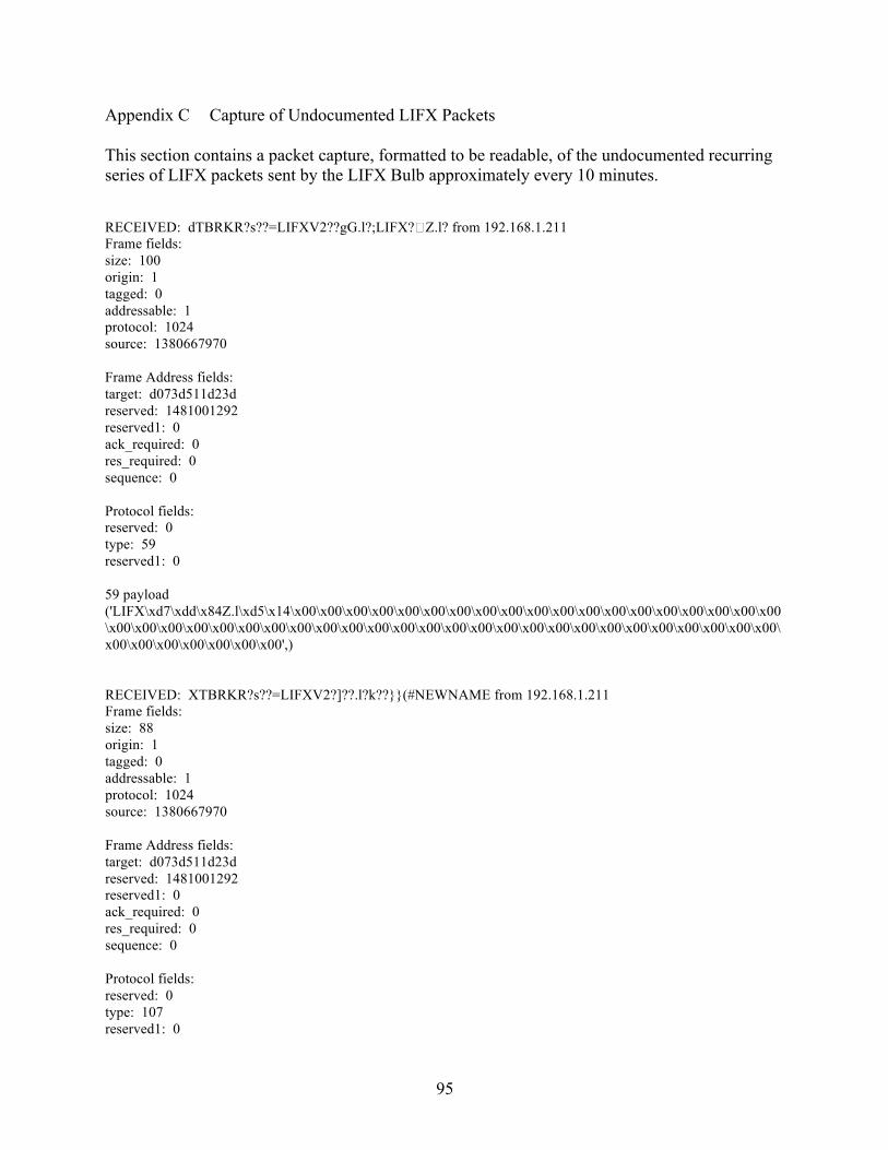
95
Appendix C Capture of Undocumented LIFX Packets This section contains a packet capture, formatted to be readable, of the undocumented recurring series of LIFX packets sent by the LIFX Bulb approximately every 10 minutes. RECEIVED: dTBRKR?s??=LIFXV2??gG.l?;LIFX? Z.l? from 192.168.1.211 Frame fields: size: 100 origin: 1 tagged: 0 addressable: 1 protocol: 1024 source: 1380667970 Frame Address fields: target: d073d511d23d reserved: 1481001292 reserved1: 0 ack_required: 0 res_required: 0 sequence: 0 Protocol fields: reserved: 0 type: 59 reserved1: 0 59 payload ('LIFX\xd7\xdd\x84Z.l\xd5\x14\x00\x00\x00\x00\x00\x00\x00\x00\x00\x00\x00\x00\x00\x00\x00\x00\x00\x00\x00\x00\x00\x00\x00\x00\x00\x00\x00\x00\x00\x00\x00\x00\x00\x00\x00\x00\x00\x00\x00\x00\x00\x00\x00\x00\x00\x00\x00\x00\x00\x00\x00\x00',) RECEIVED: XTBRKR?s??=LIFXV2?]??.l?k??}}(#NEWNAME from 192.168.1.211 Frame fields: size: 88 origin: 1 tagged: 0 addressable: 1 protocol: 1024 source: 1380667970 Frame Address fields: target: d073d511d23d reserved: 1481001292 reserved1: 0 ack_required: 0 res_required: 0 sequence: 0 Protocol fields: reserved: 0 type: 107 reserved1: 0

96
107 payload (0, 65535, 32125, 9000, 0, 0, 'NEWNAME\x00\x00\x00\x00\x00\x00\x00\x00\x00\x00\x00\x00\x00\x00\x00\x00\x00\x00\x00\x00\x00\x00\x00\x00\x00', 0) RECEIVED: &TBRKR?s??=LIFXV2???5/l?oe from 192.168.1.211 Frame fields: size: 38 origin: 1 tagged: 0 addressable: 1 protocol: 1024 source: 1380667970 Frame Address fields: target: d073d511d23d reserved: 1481001292 reserved1: 0 ack_required: 0 res_required: 0 sequence: 0 Protocol fields: reserved: 0 type: 111 reserved1: 0 111 payload ('e\x0b',) RECEIVED: 2TBRKR?s??=LIFXV2 d from 192.168.1.211 Frame fields: size: 50 origin: 1 tagged: 0 addressable: 1 protocol: 1024 source: 1380667970 Frame Address fields: target: d073d511d23d reserved: 1481001292 reserved1: 0 ack_required: 0 res_required: 0 sequence: 0 Protocol fields: reserved: 0 type: 13 reserved1: 0 13 payload (0, 0, 0, 3940)
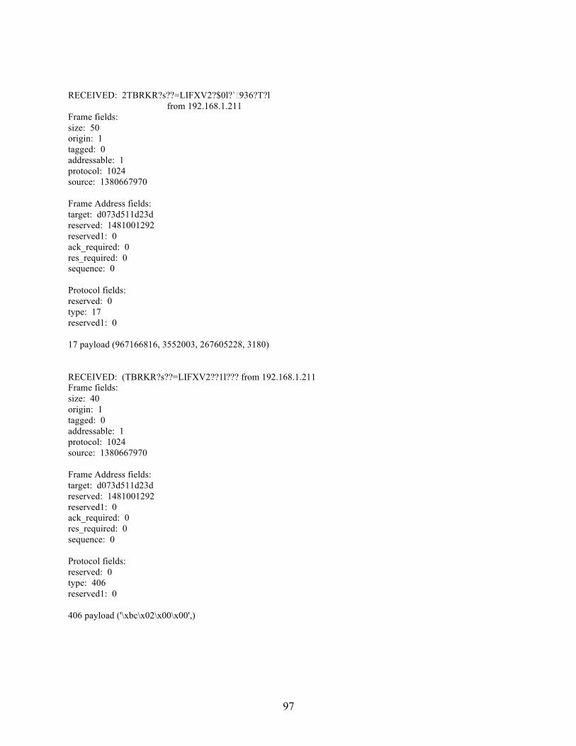
97
RECEIVED: 2TBRKR?s??=LIFXV2?$0l?`˥936?T?l from 192.168.1.211 Frame fields: size: 50 origin: 1 tagged: 0 addressable: 1 protocol: 1024 source: 1380667970 Frame Address fields: target: d073d511d23d reserved: 1481001292 reserved1: 0 ack_required: 0 res_required: 0 sequence: 0 Protocol fields: reserved: 0 type: 17 reserved1: 0 17 payload (967166816, 3552003, 267605228, 3180) RECEIVED: (TBRKR?s??=LIFXV2??1l??? from 192.168.1.211 Frame fields: size: 40 origin: 1 tagged: 0 addressable: 1 protocol: 1024 source: 1380667970 Frame Address fields: target: d073d511d23d reserved: 1481001292 reserved1: 0 ack_required: 0 res_required: 0 sequence: 0 Protocol fields: reserved: 0 type: 406 reserved1: 0 406 payload ('\xbc\x02\x00\x00',)
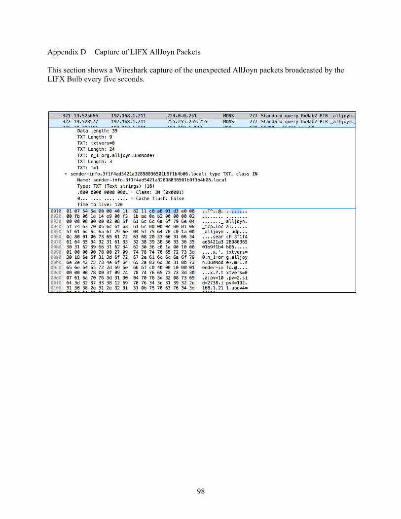
98
Appendix D Capture of LIFX AllJoyn Packets This section shows a Wireshark capture of the unexpected AllJoyn packets broadcasted by the LIFX Bulb every five seconds.
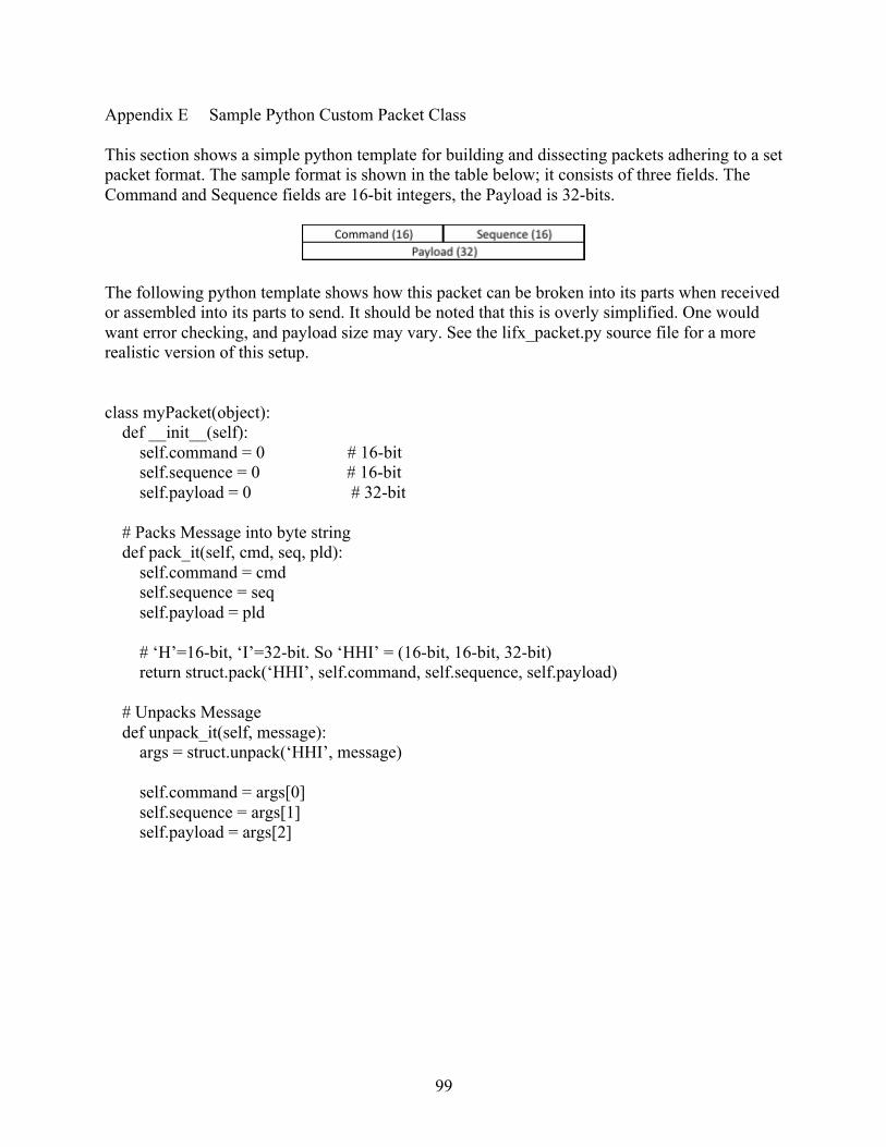
99
Appendix E Sample Python Custom Packet Class This section shows a simple python template for building and dissecting packets adhering to a set packet format. The sample format is shown in the table below; it consists of three fields. The Command and Sequence fields are 16-bit integers, the Payload is 32-bits.
The following python template shows how this packet can be broken into its parts when received or assembled into its parts to send. It should be noted that this is overly simplified. One would want error checking, and payload size may vary. See the lifx_packet.py source file for a more realistic version of this setup. class myPacket(object): def __init__(self): self.command = 0 # 16-bit self.sequence = 0 # 16-bit self.payload = 0 # 32-bit # Packs Message into byte string def pack_it(self, cmd, seq, pld): self.command = cmd self.sequence = seq self.payload = pld # ‘H’=16-bit, ‘I’=32-bit. So ‘HHI’ = (16-bit, 16-bit, 32-bit) return struct.pack(‘HHI’, self.command, self.sequence, self.payload) # Unpacks Message def unpack_it(self, message): args = struct.unpack(‘HHI’, message) self.command = args[0] self.sequence = args[1] self.payload = args[2]