simplex motion servo cncmillbf20
TRANSCRIPT
SimplexMotion Application Note
www.simplexmotion.com Draft version 2013-04-02 Page 1 of 19
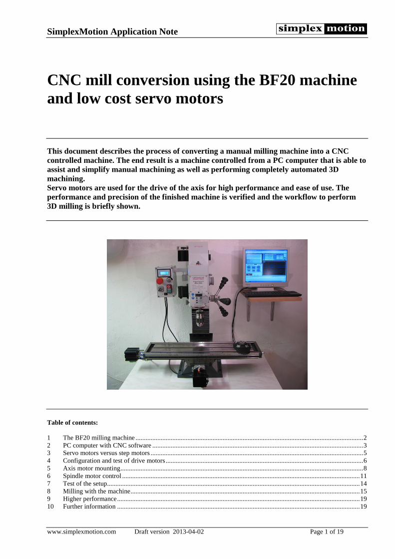
CNC mill conversion using the BF20 machine and low cost servo motors This document describes the process of converting a manual milling machine into a CNC controlled machine. The end result is a machine controlled from a PC computer that is able to assist and simplify manual machining as well as performing completely automated 3D machining. Servo motors are used for the drive of the axis for high performance and ease of use. The performance and precision of the finished machine is verified and the workflow to perform 3D milling is briefly shown.
Table of contents: 1 The BF20 milling machine ........................................................................................................................................ 2 2 PC computer with CNC software .............................................................................................................................. 3 3 Servo motors versus step motors ............................................................................................................................... 5 4 Configuration and test of drive motors ...................................................................................................................... 6 5 Axis motor mounting ................................................................................................................................................. 8 6 Spindle motor control .............................................................................................................................................. 11 7 Test of the setup....................................................................................................................................................... 14 8 Milling with the machine ......................................................................................................................................... 15 9 Higher performance ................................................................................................................................................. 19 10 Further information ................................................................................................................................................. 19
SimplexMotion Application Note
www.simplexmotion.com Draft version 2013-04-02 Page 2 of 19
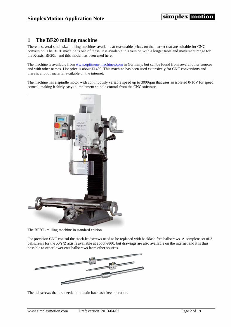
1 The BF20 milling machine There is several small size milling machines available at reasonable prices on the market that are suitable for CNC conversion. The BF20 machine is one of these. It is available in a version with a longer table and movement range for the X-axis, BF20L, and this model has been used here. The machine is available from www.optimum-machines.com in Germany, but can be found from several other sources and with other names. List price is about €1400. This machine has been used extensively for CNC conversions and there is a lot of material available on the internet. The machine has a spindle motor with continuously variable speed up to 3000rpm that uses an isolated 0-10V for speed control, making it fairly easy to implement spindle control from the CNC software.
The BF20L milling machine in standard edition For precision CNC control the stock leadscrews need to be replaced with backlash free ballscrews. A complete set of 3 ballscrews for the X/Y/Z axis is available at about €800, but drawings are also available on the internet and it is thus possible to order lower cost ballscrews from other sources.
The ballscrews that are needed to obtain backlash free operation.
SimplexMotion Application Note
www.simplexmotion.com Draft version 2013-04-02 Page 3 of 19
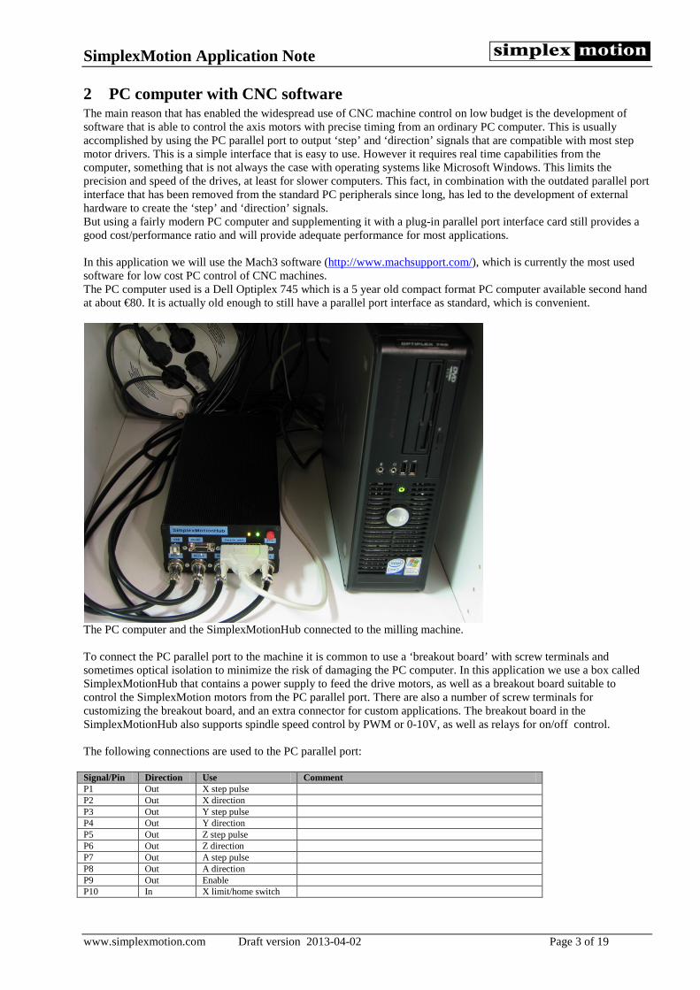
2 PC computer with CNC software The main reason that has enabled the widespread use of CNC machine control on low budget is the development of software that is able to control the axis motors with precise timing from an ordinary PC computer. This is usually accomplished by using the PC parallel port to output ‘step’ and ‘direction’ signals that are compatible with most step motor drivers. This is a simple interface that is easy to use. However it requires real time capabilities from the computer, something that is not always the case with operating systems like Microsoft Windows. This limits the precision and speed of the drives, at least for slower computers. This fact, in combination with the outdated parallel port interface that has been removed from the standard PC peripherals since long, has led to the development of external hardware to create the ‘step’ and ‘direction’ signals. But using a fairly modern PC computer and supplementing it with a plug-in parallel port interface card still provides a good cost/performance ratio and will provide adequate performance for most applications. In this application we will use the Mach3 software (http://www.machsupport.com/), which is currently the most used software for low cost PC control of CNC machines. The PC computer used is a Dell Optiplex 745 which is a 5 year old compact format PC computer available second hand at about €80. It is actually old enough to still have a parallel port interface as standard, which is convenient.
The PC computer and the SimplexMotionHub connected to the milling machine. To connect the PC parallel port to the machine it is common to use a ‘breakout board’ with screw terminals and sometimes optical isolation to minimize the risk of damaging the PC computer. In this application we use a box called SimplexMotionHub that contains a power supply to feed the drive motors, as well as a breakout board suitable to control the SimplexMotion motors from the PC parallel port. There are also a number of screw terminals for customizing the breakout board, and an extra connector for custom applications. The breakout board in the SimplexMotionHub also supports spindle speed control by PWM or 0-10V, as well as relays for on/off control. The following connections are used to the PC parallel port: Signal/Pin Direction Use Comment P1 Out X step pulse P2 Out X direction P3 Out Y step pulse P4 Out Y direction P5 Out Z step pulse P6 Out Z direction P7 Out A step pulse P8 Out A direction P9 Out Enable P10 In X limit/home switch
SimplexMotion Application Note
www.simplexmotion.com Draft version 2013-04-02 Page 4 of 19
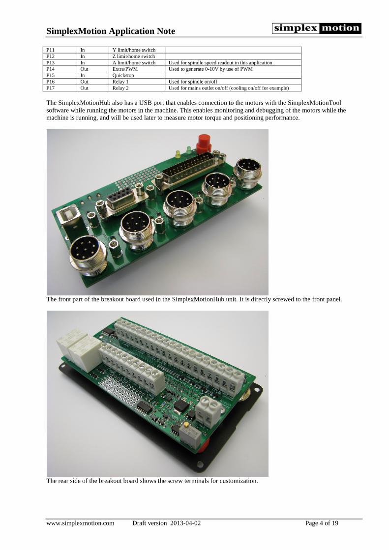
P11 In Y limit/home switch P12 In Z limit/home switch P13 In A limit/home switch Used for spindle speed readout in this application P14 Out Extra/PWM Used to generate 0-10V by use of PWM P15 In Quickstop P16 Out Relay 1 Used for spindle on/off P17 Out Relay 2 Used for mains outlet on/off (cooling on/off for example) The SimplexMotionHub also has a USB port that enables connection to the motors with the SimplexMotionTool software while running the motors in the machine. This enables monitoring and debugging of the motors while the machine is running, and will be used later to measure motor torque and positioning performance.
The front part of the breakout board used in the SimplexMotionHub unit. It is directly screwed to the front panel.
The rear side of the breakout board shows the screw terminals for customization.

SimplexMotion Application Note
www.simplexmotion.com Draft version 2013-04-02 Page 5 of 19
3 Servo motors versus step motors Most low cost mill conversions utilize step motors, since they are very affordable and easy to get and use. However these motors have a few drawbacks:
• Step motors are used in an open loop fashion, there is no position feedback. This means that if the motor loses some steps it will have a position error for the remainder of the working session.
• They have a large holding torque, but the torque falls off quickly as the rotational speed is increased. This makes it difficult to attain high speeds.
• The step nature of the motor creates vibrations and noise at certain speeds which can be annoying and in some cases affect the finish of the machined parts.
• They consume lots of electrical power and get quite hot, since they need continuous current to maintain torque. • The step motors are fairly heavy and large.
In high end applications servo motors are used to overcome these issues. The servo motor system uses a motor and a position encoder to measure the true position. The driver controller compares the actual position with the target position and controls the motor torque to minimize this difference, thus closing the control loop. This allows the motor to consume power only when necessary and error conditions such as tool/work piece collisions can be detected and stop the machine. Servo motors can also maintain a high torque at high speeds, at least for brief moments. They also have a higher power-to-weight ratio and usually run much quieter.
Comparison of torque between a typical step motor and the used servo motor. One reason the servo motors have been so much more expensive is the added electronics needed for their control. But due to the ever increasing cost efficiency of electronics this is beginning to change. With integrated motor control units, where the electronics is integrated with the motor, the added cost for servomotors is quickly decreasing. One example of this is the SimplexMotion concept. It is a small and cost optimized servo motor system with integrated electronics. It is based on a high torque outer rotor brushless motor and a novel patented technology for motor position sensing. It has a USB port for control and configuration, but also offers other means of control. One of these is a ‘step/direction’ interface that is compatible to most step motor drives. This makes it easy to use for CNC conversion projects. The SimplexMotion100A model is capable of 100W output power and 1.5Nm torque, which is suitable for direct drive of ballscrews on CNC milling machines. Since torque can be maintained at speed much better than step motors, and the use of position feedback, this motor can replace step motors rated at holding torques of 4-6Nm. More information on these motors is available at www.simplexmotion.com.
SimplexMotion Application Note
www.simplexmotion.com Draft version 2013-04-02 Page 6 of 19
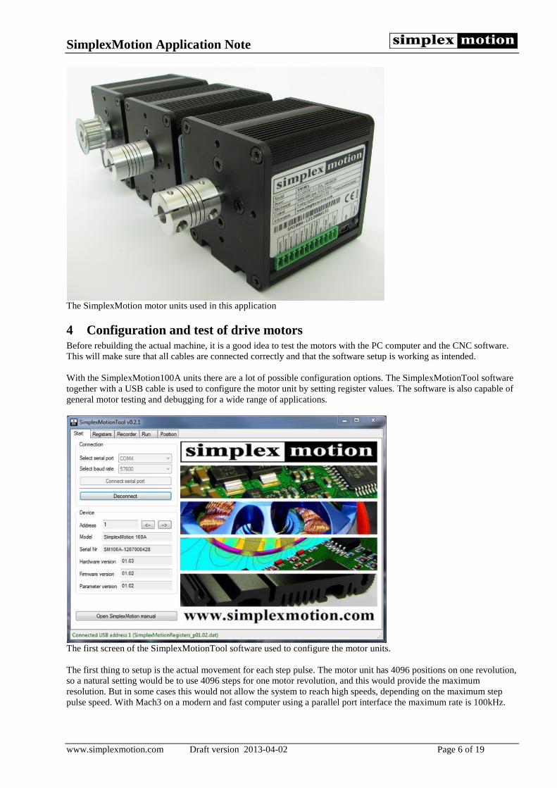
The SimplexMotion motor units used in this application
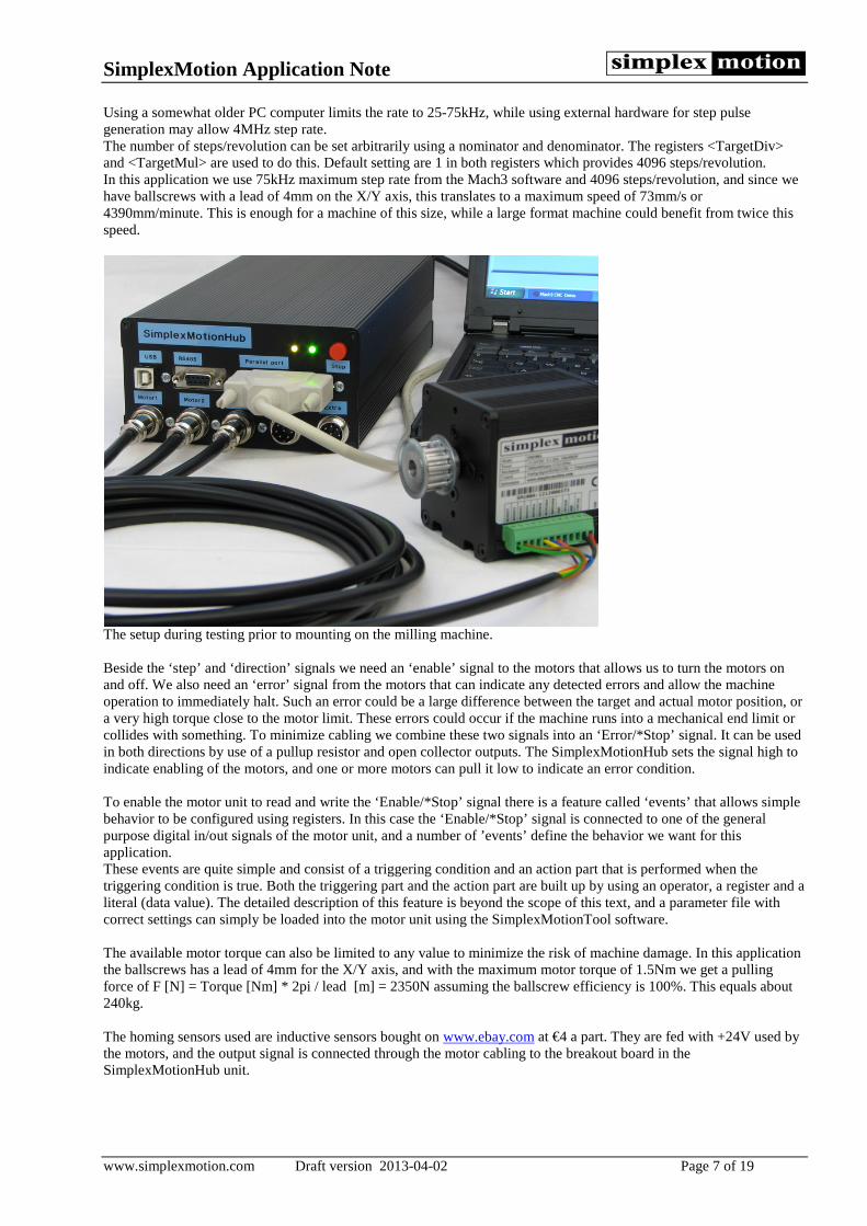
4 Configuration and test of drive motors Before rebuilding the actual machine, it is a good idea to test the motors with the PC computer and the CNC software. This will make sure that all cables are connected correctly and that the software setup is working as intended. With the SimplexMotion100A units there are a lot of possible configuration options. The SimplexMotionTool software together with a USB cable is used to configure the motor unit by setting register values. The software is also capable of general motor testing and debugging for a wide range of applications.
The first screen of the SimplexMotionTool software used to configure the motor units. The first thing to setup is the actual movement for each step pulse. The motor unit has 4096 positions on one revolution, so a natural setting would be to use 4096 steps for one motor revolution, and this would provide the maximum resolution. But in some cases this would not allow the system to reach high speeds, depending on the maximum step pulse speed. With Mach3 on a modern and fast computer using a parallel port interface the maximum rate is 100kHz.
SimplexMotion Application Note
www.simplexmotion.com Draft version 2013-04-02 Page 7 of 19
Using a somewhat older PC computer limits the rate to 25-75kHz, while using external hardware for step pulse generation may allow 4MHz step rate. The number of steps/revolution can be set arbitrarily using a nominator and denominator. The registers <TargetDiv> and <TargetMul> are used to do this. Default setting are 1 in both registers which provides 4096 steps/revolution. In this application we use 75kHz maximum step rate from the Mach3 software and 4096 steps/revolution, and since we have ballscrews with a lead of 4mm on the X/Y axis, this translates to a maximum speed of 73mm/s or 4390mm/minute. This is enough for a machine of this size, while a large format machine could benefit from twice this speed.
The setup during testing prior to mounting on the milling machine. Beside the ‘step’ and ‘direction’ signals we need an ‘enable’ signal to the motors that allows us to turn the motors on and off. We also need an ‘error’ signal from the motors that can indicate any detected errors and allow the machine operation to immediately halt. Such an error could be a large difference between the target and actual motor position, or a very high torque close to the motor limit. These errors could occur if the machine runs into a mechanical end limit or collides with something. To minimize cabling we combine these two signals into an ‘Error/*Stop’ signal. It can be used in both directions by use of a pullup resistor and open collector outputs. The SimplexMotionHub sets the signal high to indicate enabling of the motors, and one or more motors can pull it low to indicate an error condition. To enable the motor unit to read and write the ‘Enable/*Stop’ signal there is a feature called ‘events’ that allows simple behavior to be configured using registers. In this case the ‘Enable/*Stop’ signal is connected to one of the general purpose digital in/out signals of the motor unit, and a number of ’events’ define the behavior we want for this application. These events are quite simple and consist of a triggering condition and an action part that is performed when the triggering condition is true. Both the triggering part and the action part are built up by using an operator, a register and a literal (data value). The detailed description of this feature is beyond the scope of this text, and a parameter file with correct settings can simply be loaded into the motor unit using the SimplexMotionTool software. The available motor torque can also be limited to any value to minimize the risk of machine damage. In this application the ballscrews has a lead of 4mm for the X/Y axis, and with the maximum motor torque of 1.5Nm we get a pulling force of F [N] = Torque [Nm] * 2pi / lead [m] = 2350N assuming the ballscrew efficiency is 100%. This equals about 240kg. The homing sensors used are inductive sensors bought on www.ebay.com at €4 a part. They are fed with +24V used by the motors, and the output signal is connected through the motor cabling to the breakout board in the SimplexMotionHub unit.
SimplexMotion Application Note
www.simplexmotion.com Draft version 2013-04-02 Page 8 of 19
5 Axis motor mounting Mechanical parts for mounting the axis drive motors were made from aluminum by water jet cutting. Thickness of 5 and 10mm was used. The parts enable mounting of the drive motors and the inductive home sensors. The motors for X and Y axis are mounted with direct drive, while the Z axis motor mounting utilizes a tooth belt transmission. Using direct drive where it is possible is important since an intermediary gearbox will introduce backlash and loss of precision.
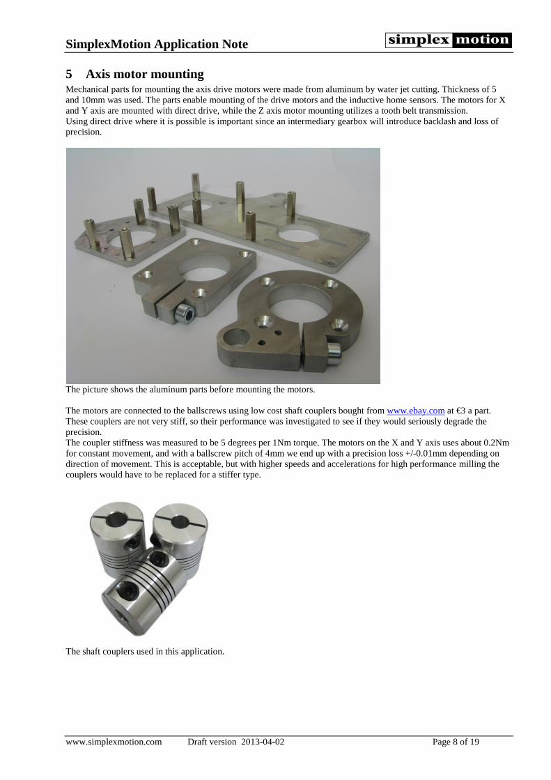
The picture shows the aluminum parts before mounting the motors. The motors are connected to the ballscrews using low cost shaft couplers bought from www.ebay.com at €3 a part. These couplers are not very stiff, so their performance was investigated to see if they would seriously degrade the precision. The coupler stiffness was measured to be 5 degrees per 1Nm torque. The motors on the X and Y axis uses about 0.2Nm for constant movement, and with a ballscrew pitch of 4mm we end up with a precision loss +/-0.01mm depending on direction of movement. This is acceptable, but with higher speeds and accelerations for high performance milling the couplers would have to be replaced for a stiffer type.
The shaft couplers used in this application.
SimplexMotion Application Note
www.simplexmotion.com Draft version 2013-04-02 Page 9 of 19
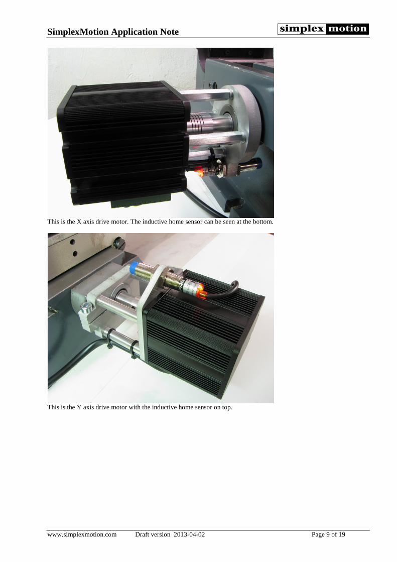
This is the X axis drive motor. The inductive home sensor can be seen at the bottom.
This is the Y axis drive motor with the inductive home sensor on top.
SimplexMotion Application Note
www.simplexmotion.com Draft version 2013-04-02 Page 10 of 19
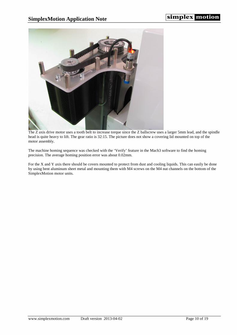
The Z axis drive motor uses a tooth belt to increase torque since the Z ballscrew uses a larger 5mm lead, and the spindle head is quite heavy to lift. The gear ratio is 32:15. The picture does not show a covering lid mounted on top of the motor assembly. The machine homing sequence was checked with the ‘Verify’ feature in the Mach3 software to find the homing precision. The average homing position error was about 0.02mm. For the X and Y axis there should be covers mounted to protect from dust and cooling liquids. This can easily be done by using bent aluminum sheet metal and mounting them with M4 screws on the M4 nut channels on the bottom of the SimplexMotion motor units.
SimplexMotion Application Note
www.simplexmotion.com Draft version 2013-04-02 Page 11 of 19
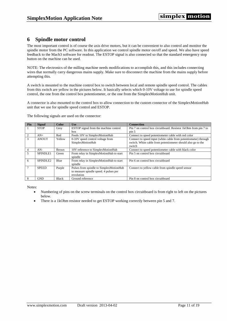
6 Spindle motor control The most important control is of course the axis drive motors, but it can be convenient to also control and monitor the spindle motor from the PC software. In this application we control spindle motor on/off and speed. We also have speed feedback to the Mach3 software for readout. The ESTOP signal is also connected so that the standard emergency stop button on the machine can be used. NOTE: The electronics of the milling machine needs modifications to accomplish this, and this includes connecting wires that normally carry dangerous mains supply. Make sure to disconnect the machine from the mains supply before attempting this. A switch is mounted to the machine control box to switch between local and remote spindle speed control. The cables from this switch are yellow in the pictures below. It basically selects which 0-10V voltage to use for spindle speed control, the one from the control box potentiometer, or the one from the SimplexMotionHub unit. A connector is also mounted to the control box to allow connection to the custom connector of the SimplexMotionHub unit that we use for spindle speed control and ESTOP. The following signals are used on the connector: Pin Signal Color Use Connection 1 STOP Grey ESTOP signal from the machine control
box Pin 7 on control box circuitboard. Resistor 1kOhm from pin 7 to pin 5
2 AN+ Red Feeds 10V to SimplexMotionHub Connect to speed potentiometer cable with red color 3 ANOUT Yellow 0-10V speed control voltage from
SimplexMotionHub Connect to speed input (white cable from potentiometer) through switch. White cable from potentiometer should also go to the switch
4 AN- Brown 10V reference to SimplexMotionHub Connect to speed potentiometer cable with black color 5 SPINDLE1 Green From relay in SimplexMotionHub to start
spindle Pin 5 on control box circuitboard
6 SPINDLE2 Blue From relay in SimplexMotionHub to start spindle
Pin 6 on control box circuitboard
7 SPEED Purple Pulses from spindle to SimplexMotionHub to measure spindle speed. 4 pulses per revolution
Connect to yellow cable from spindle speed sensor
8 GND Black Ground reference Pin 8 on control box circuitboard Notes:
• Numbering of pins on the screw terminals on the control box circuitboard is from right to left on the pictures below.
• There is a 1kOhm resistor needed to get ESTOP working correctly between pin 5 and 7.

SimplexMotion Application Note
www.simplexmotion.com Draft version 2013-04-02 Page 12 of 19
There is a switch mounted to the side of the control box to select spindle speed control source.
A connector is mounted to the bottom of the control box for a cable connection to the custom connector on the SimplexMotionHub unit.
SimplexMotion Application Note
www.simplexmotion.com Draft version 2013-04-02 Page 13 of 19
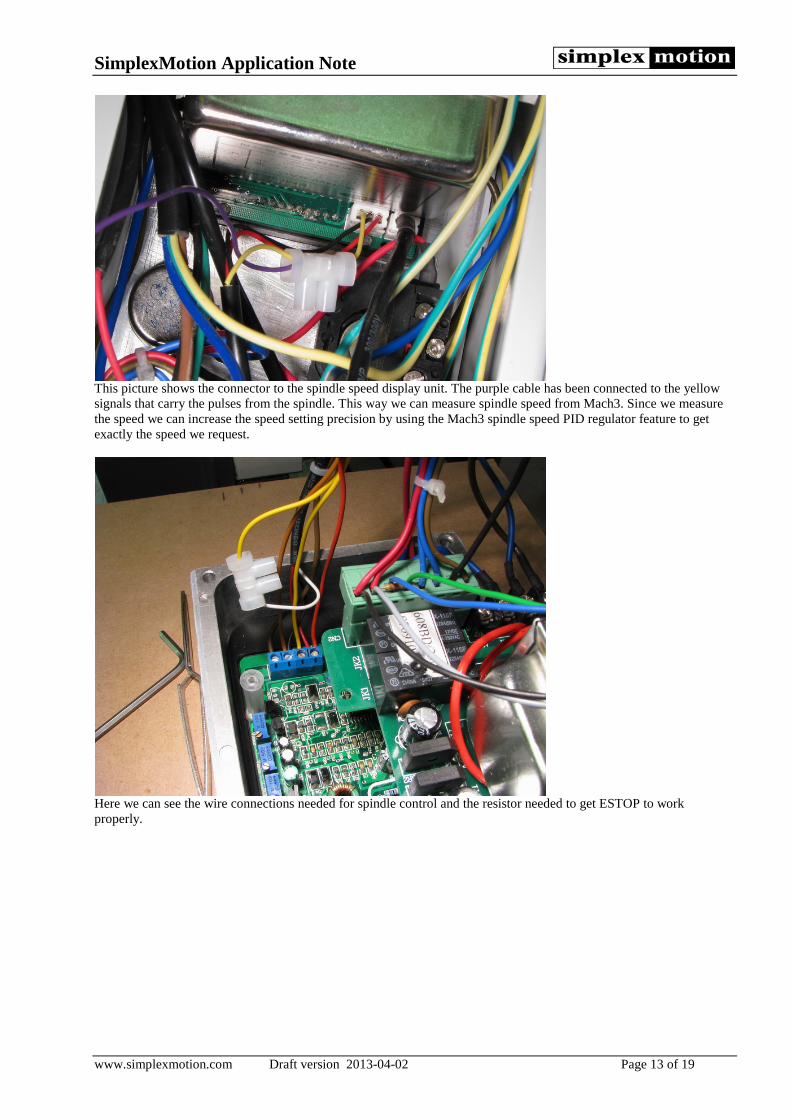
This picture shows the connector to the spindle speed display unit. The purple cable has been connected to the yellow signals that carry the pulses from the spindle. This way we can measure spindle speed from Mach3. Since we measure the speed we can increase the speed setting precision by using the Mach3 spindle speed PID regulator feature to get exactly the speed we request.
Here we can see the wire connections needed for spindle control and the resistor needed to get ESTOP to work properly.
SimplexMotion Application Note
www.simplexmotion.com Draft version 2013-04-02 Page 14 of 19
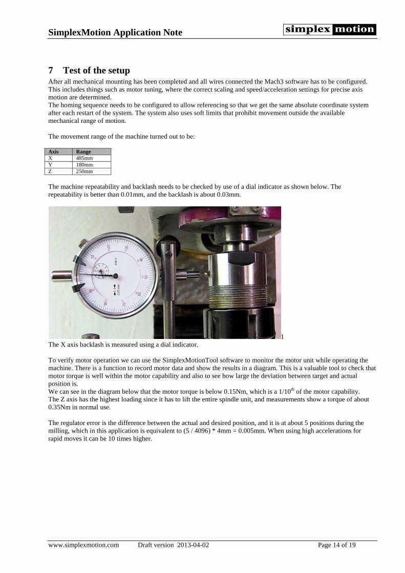
7 Test of the setup After all mechanical mounting has been completed and all wires connected the Mach3 software has to be configured. This includes things such as motor tuning, where the correct scaling and speed/acceleration settings for precise axis motion are determined. The homing sequence needs to be configured to allow referencing so that we get the same absolute coordinate system after each restart of the system. The system also uses soft limits that prohibit movement outside the available mechanical range of motion. The movement range of the machine turned out to be: Axis Range X 485mm Y 180mm Z 250mm The machine repeatability and backlash needs to be checked by use of a dial indicator as shown below. The repeatability is better than 0.01mm, and the backlash is about 0.03mm.
1 The X axis backlash is measured using a dial indicator. To verify motor operation we can use the SimplexMotionTool software to monitor the motor unit while operating the machine. There is a function to record motor data and show the results in a diagram. This is a valuable tool to check that motor torque is well within the motor capability and also to see how large the deviation between target and actual position is. We can see in the diagram below that the motor torque is below 0.15Nm, which is a 1/10th of the motor capability. The Z axis has the highest loading since it has to lift the entire spindle unit, and measurements show a torque of about 0.35Nm in normal use. The regulator error is the difference between the actual and desired position, and it is at about 5 positions during the milling, which in this application is equivalent to (5 / 4096) * 4mm = 0.005mm. When using high accelerations for rapid moves it can be 10 times higher.

SimplexMotion Application Note
www.simplexmotion.com Draft version 2013-04-02 Page 15 of 19
Recording of X axis motor data while milling a circle in 400mm/m speed. At the end of the circle there is a rapid move.
8 Milling with the machine By using a good pendant control it is quite possible to do manual milling operations, with the added benefits of digital position indicators on the Mach3 screen. But simple milling operations can in most cases be done in a semi-automatic fashion using the built in wizards in the Mach3 software. This includes text routing as shown below, but also circular hole patterns, pocket milling, surface milling and much more. The following pictures show some milling examples performed at feed rates of 300-800mm/minute.
It is quick and easy to do text routing.
SimplexMotion Application Note
www.simplexmotion.com Draft version 2013-04-02 Page 16 of 19
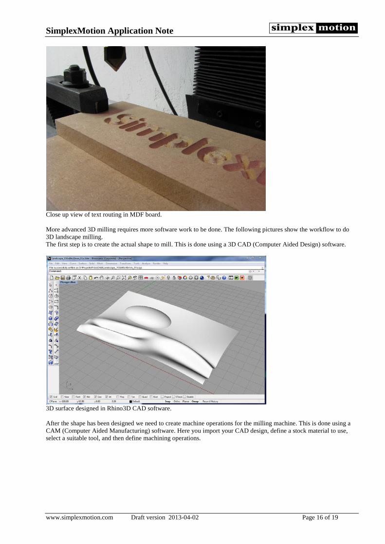
Close up view of text routing in MDF board. More advanced 3D milling requires more software work to be done. The following pictures show the workflow to do 3D landscape milling. The first step is to create the actual shape to mill. This is done using a 3D CAD (Computer Aided Design) software.
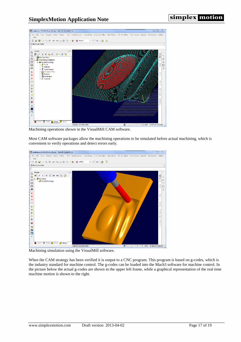
3D surface designed in Rhino3D CAD software. After the shape has been designed we need to create machine operations for the milling machine. This is done using a CAM (Computer Aided Manufacturing) software. Here you import your CAD design, define a stock material to use, select a suitable tool, and then define machining operations.
SimplexMotion Application Note
www.simplexmotion.com Draft version 2013-04-02 Page 17 of 19
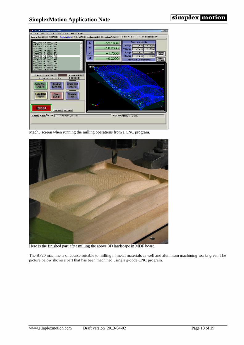
Machining operations shown in the VisualMill CAM software. Most CAM software packages allow the machining operations to be simulated before actual machining, which is convenient to verify operations and detect errors early.
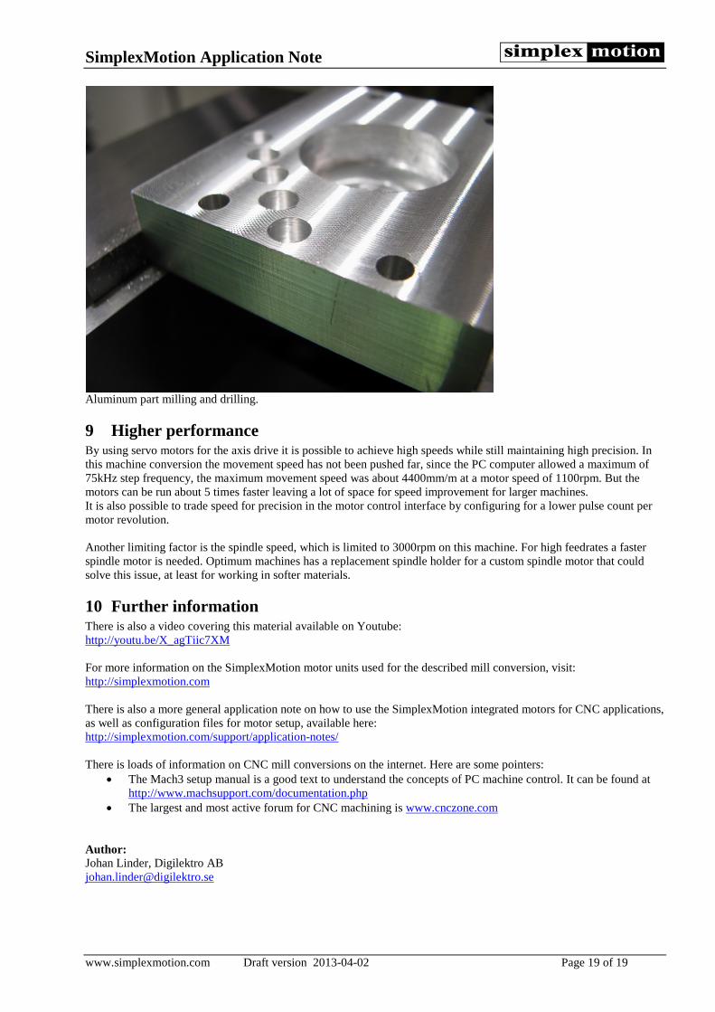
Machining simulation using the VisualMill software. When the CAM strategy has been verified it is output to a CNC program. This program is based on g-codes, which is the industry standard for machine control. The g-codes can be loaded into the Mach3 software for machine control. In the picture below the actual g-codes are shown in the upper left frame, while a graphical representation of the real time machine motion is shown to the right.
SimplexMotion Application Note
www.simplexmotion.com Draft version 2013-04-02 Page 18 of 19
Mach3 screen when running the milling operations from a CNC program.
Here is the finished part after milling the above 3D landscape in MDF board. The BF20 machine is of course suitable to milling in metal materials as well and aluminum machining works great. The picture below shows a part that has been machined using a g-code CNC program.
SimplexMotion Application Note
www.simplexmotion.com Draft version 2013-04-02 Page 19 of 19
Aluminum part milling and drilling.
9 Higher performance By using servo motors for the axis drive it is possible to achieve high speeds while still maintaining high precision. In this machine conversion the movement speed has not been pushed far, since the PC computer allowed a maximum of 75kHz step frequency, the maximum movement speed was about 4400mm/m at a motor speed of 1100rpm. But the motors can be run about 5 times faster leaving a lot of space for speed improvement for larger machines. It is also possible to trade speed for precision in the motor control interface by configuring for a lower pulse count per motor revolution. Another limiting factor is the spindle speed, which is limited to 3000rpm on this machine. For high feedrates a faster spindle motor is needed. Optimum machines has a replacement spindle holder for a custom spindle motor that could solve this issue, at least for working in softer materials.
10 Further information There is also a video covering this material available on Youtube: http://youtu.be/X_agTiic7XM For more information on the SimplexMotion motor units used for the described mill conversion, visit: http://simplexmotion.com There is also a more general application note on how to use the SimplexMotion integrated motors for CNC applications, as well as configuration files for motor setup, available here: http://simplexmotion.com/support/application-notes/ There is loads of information on CNC mill conversions on the internet. Here are some pointers:
• The Mach3 setup manual is a good text to understand the concepts of PC machine control. It can be found at http://www.machsupport.com/documentation.php
• The largest and most active forum for CNC machining is www.cnczone.com Author: Johan Linder, Digilektro AB [email protected]