simatic s7 3964(r)/ rk512 driver · simatic s7 3964(r)/rk512 driver gp-pro ex device/plc connection...
TRANSCRIPT
1
Siemens AG
SIMATIC S7 3964(R)/RK512 Driver
1 System Configuration....................................................................................................... 3
2 Selection of External Device ............................................................................................ 7
3 Example of Communication Setting ................................................................................. 8
4 Setup Items .................................................................................................................... 20
5 Cable Diagram ............................................................................................................... 25
6 Supported Device........................................................................................................... 30
7 Device Code and Address Code.................................................................................... 31
8 Error Messages.............................................................................................................. 32
SIMATIC S7 3964(R)/RK512 Driver
GP-Pro EX Device/PLC Connection Manual 2
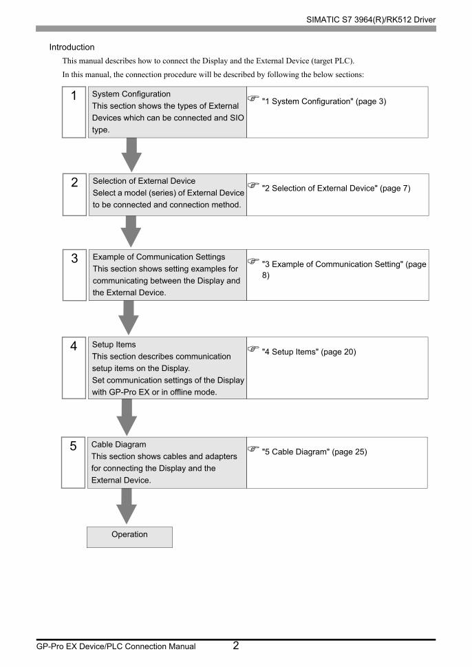
Introduction
This manual describes how to connect the Display and the External Device (target PLC).
In this manual, the connection procedure will be described by following the below sections:
1 System Configuration
This section shows the types of External
Devices which can be connected and SIO
type.
"1 System Configuration" (page 3)
2 Selection of External Device
Select a model (series) of External Device
to be connected and connection method.
"2 Selection of External Device" (page 7)
3 Example of Communication Settings
This section shows setting examples for
communicating between the Display and
the External Device.
"3 Example of Communication Setting" (page 8)
4 Setup Items
This section describes communication
setup items on the Display.
Set communication settings of the Display
with GP-Pro EX or in offline mode.
"4 Setup Items" (page 20)
5 Cable Diagram
This section shows cables and adapters
for connecting the Display and the
External Device.
"5 Cable Diagram" (page 25)
Operation
SIMATIC S7 3964(R)/RK512 Driver
GP-Pro EX Device/PLC Connection Manual 3
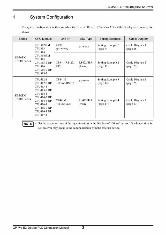
1 System Configuration
The system configuration in the case when the External Device of Siemens AG and the Display are connected is
shown.
Series CPU Module Link I/F SIO Type Setting Example Cable Diagram
SIMATICS7-300 Series
CPU312IFMCPU313CPU314CPU314IFMCPU315CPU315-2 DPCPU316CPU316-2 DPCPU318-2
CP341
(RS232C)RS232C
Setting Example 1 (page 8)
Cable Diagram 1 (page 25)
CP341 (RS422/485)
RS422/485 (4wire)
Setting Example 2 (page 11)
Cable Diagram 2 (page 27)
SIMATICS7-400 Series
CPU412-1CPU412-2 DPCPU413-1CPU413-2 DPCPU414-1CPU414-2 DPCPU414-3 DPCPU416-1CPU416-2 DPCPU416-3 DPCPU417-4
CP441-2+ IF963-RS232
RS232CSetting Example 3 (page 14)
Cable Diagram 1 (page 25)
CP441-2+ IF963-X27
RS422/485 (4wire)
Setting Example 4 (page 17)
Cable Diagram 2 (page 27)
• Set the execution time of the logic functions in the Display to "100 ms" or less. If the longer time is
set, an error may occur in the communication with the external device.
SIMATIC S7 3964(R)/RK512 Driver
GP-Pro EX Device/PLC Connection Manual 4
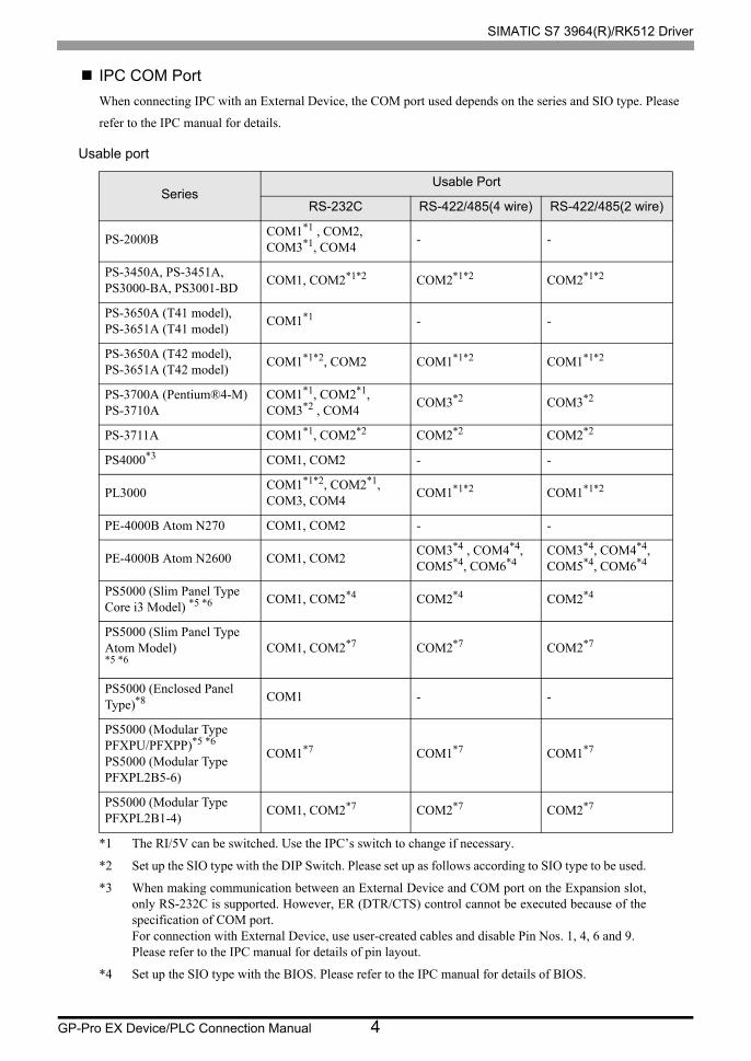
IPC COM Port
When connecting IPC with an External Device, the COM port used depends on the series and SIO type. Please
refer to the IPC manual for details.
Usable port
SeriesUsable Port
RS-232C RS-422/485(4 wire) RS-422/485(2 wire)
PS-2000BCOM1*1 , COM2, COM3*1, COM4
*1 The RI/5V can be switched. Use the IPC’s switch to change if necessary.
- -
PS-3450A, PS-3451A,PS3000-BA, PS3001-BD
COM1, COM2*1*2 COM2*1*2 COM2*1*2
PS-3650A (T41 model),PS-3651A (T41 model)
COM1*1 - -
PS-3650A (T42 model),PS-3651A (T42 model)
COM1*1*2, COM2 COM1*1*2 COM1*1*2
PS-3700A (Pentium®4-M)PS-3710A
COM1*1, COM2*1, COM3*2 , COM4
*2 Set up the SIO type with the DIP Switch. Please set up as follows according to SIO type to be used.
COM3*2 COM3*2
PS-3711A COM1*1, COM2*2 COM2*2 COM2*2
PS4000*3
*3 When making communication between an External Device and COM port on the Expansion slot, only RS-232C is supported. However, ER (DTR/CTS) control cannot be executed because of the specification of COM port.For connection with External Device, use user-created cables and disable Pin Nos. 1, 4, 6 and 9.Please refer to the IPC manual for details of pin layout.
COM1, COM2 - -
PL3000COM1*1*2, COM2*1, COM3, COM4
COM1*1*2 COM1*1*2
PE-4000B Atom N270 COM1, COM2 - -
PE-4000B Atom N2600 COM1, COM2COM3*4 , COM4*4, COM5*4, COM6*4
*4 Set up the SIO type with the BIOS. Please refer to the IPC manual for details of BIOS.
COM3*4, COM4*4, COM5*4, COM6*4
PS5000 (Slim Panel Type Core i3 Model) *5 *6 COM1, COM2*4 COM2*4 COM2*4
PS5000 (Slim Panel Type Atom Model) *5 *6
COM1, COM2*7 COM2*7 COM2*7
PS5000 (Enclosed Panel Type)*8 COM1 - -
PS5000 (Modular Type PFXPU/PFXPP)*5 *6
PS5000 (Modular Type PFXPL2B5-6)
COM1*7 COM1*7 COM1*7
PS5000 (Modular Type PFXPL2B1-4)
COM1, COM2*7 COM2*7 COM2*7
SIMATIC S7 3964(R)/RK512 Driver
GP-Pro EX Device/PLC Connection Manual 5
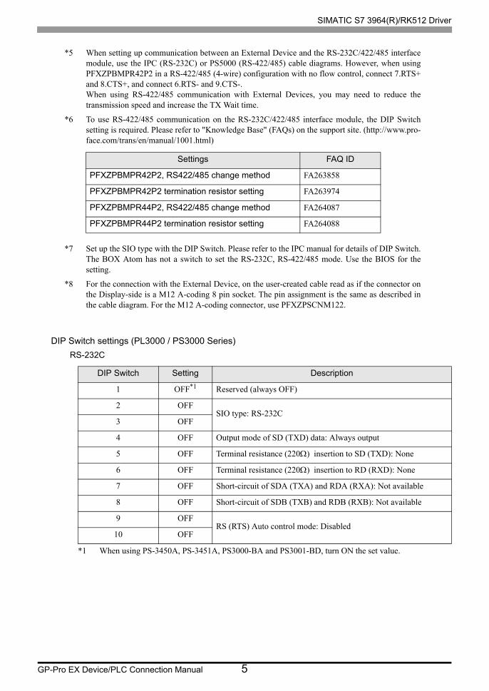
DIP Switch settings (PL3000 / PS3000 Series)
RS-232C
*5 When setting up communication between an External Device and the RS-232C/422/485 interface module, use the IPC (RS-232C) or PS5000 (RS-422/485) cable diagrams. However, when using PFXZPBMPR42P2 in a RS-422/485 (4-wire) configuration with no flow control, connect 7.RTS+ and 8.CTS+, and connect 6.RTS- and 9.CTS-.When using RS-422/485 communication with External Devices, you may need to reduce the transmission speed and increase the TX Wait time.
*6 To use RS-422/485 communication on the RS-232C/422/485 interface module, the DIP Switch setting is required. Please refer to "Knowledge Base" (FAQs) on the support site. (http://www.pro- face.com/trans/en/manual/1001.html)
*7 Set up the SIO type with the DIP Switch. Please refer to the IPC manual for details of DIP Switch.The BOX Atom has not a switch to set the RS-232C, RS-422/485 mode. Use the BIOS for the setting.
*8 For the connection with the External Device, on the user-created cable read as if the connector on the Display-side is a M12 A-coding 8 pin socket. The pin assignment is the same as described in the cable diagram. For the M12 A-coding connector, use PFXZPSCNM122.
DIP Switch Setting Description
1 OFF*1
*1 When using PS-3450A, PS-3451A, PS3000-BA and PS3001-BD, turn ON the set value.
Reserved (always OFF)
2 OFFSIO type: RS-232C
3 OFF
4 OFF Output mode of SD (TXD) data: Always output
5 OFF Terminal resistance (220) insertion to SD (TXD): None
6 OFF Terminal resistance (220) insertion to RD (RXD): None
7 OFF Short-circuit of SDA (TXA) and RDA (RXA): Not available
8 OFF Short-circuit of SDB (TXB) and RDB (RXB): Not available
9 OFFRS (RTS) Auto control mode: Disabled
10 OFF
Settings FAQ ID
PFXZPBMPR42P2, RS422/485 change method FA263858
PFXZPBMPR42P2 termination resistor setting FA263974
PFXZPBMPR44P2, RS422/485 change method FA264087
PFXZPBMPR44P2 termination resistor setting FA264088
SIMATIC S7 3964(R)/RK512 Driver
GP-Pro EX Device/PLC Connection Manual 6
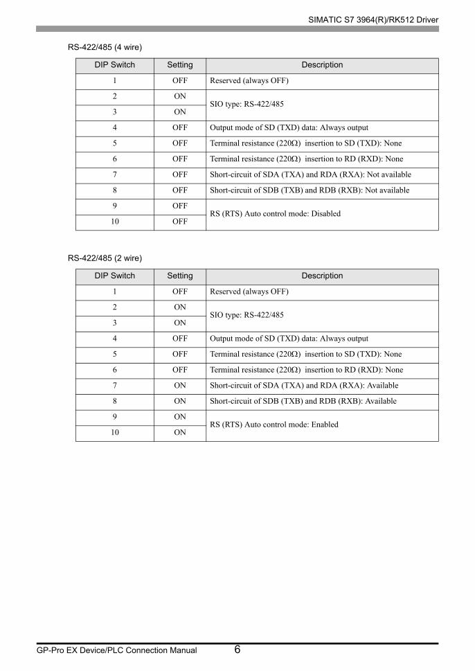
RS-422/485 (4 wire)
RS-422/485 (2 wire)
DIP Switch Setting Description
1 OFF Reserved (always OFF)
2 ONSIO type: RS-422/485
3 ON
4 OFF Output mode of SD (TXD) data: Always output
5 OFF Terminal resistance (220) insertion to SD (TXD): None
6 OFF Terminal resistance (220) insertion to RD (RXD): None
7 OFF Short-circuit of SDA (TXA) and RDA (RXA): Not available
8 OFF Short-circuit of SDB (TXB) and RDB (RXB): Not available
9 OFFRS (RTS) Auto control mode: Disabled
10 OFF
DIP Switch Setting Description
1 OFF Reserved (always OFF)
2 ONSIO type: RS-422/485
3 ON
4 OFF Output mode of SD (TXD) data: Always output
5 OFF Terminal resistance (220) insertion to SD (TXD): None
6 OFF Terminal resistance (220) insertion to RD (RXD): None
7 ON Short-circuit of SDA (TXA) and RDA (RXA): Available
8 ON Short-circuit of SDB (TXB) and RDB (RXB): Available
9 ONRS (RTS) Auto control mode: Enabled
10 ON
SIMATIC S7 3964(R)/RK512 Driver
GP-Pro EX Device/PLC Connection Manual 7
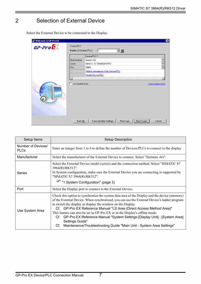
2 Selection of External Device
Select the External Device to be connected to the Display.
Setup Items Setup Description
Number of Devices/PLCs
Enter an integer from 1 to 4 to define the number of Devices/PLCs to connect to the display.
Manufacturer Select the manufacturer of the External Device to connect. Select "Siemens AG".
Series
Select the External Device model (series) and the connection method. Select "SIMATIC S7 3964(R)/RK512".In System configuration, make sure the External Device you are connecting is supported by "SIMATIC S7 3964(R)/RK512".
"1 System Configuration" (page 3)
Port Select the Display port to connect to the External Device.
Use System Area
Check this option to synchronize the system data area of the Display and the device (memory) of the External Device. When synchronized, you can use the External Device’s ladder program to switch the display or display the window on the Display.
Cf. GP-Pro EX Reference Manual "LS Area (Direct Access Method Area)"This feature can also be set in GP-Pro EX or in the Display's offline mode.
Cf. GP-Pro EX Reference Manual "System Settings [Display Unit] - [System Area] Settings Guide"
Cf. Maintenance/Troubleshooting Guide "Main Unit - System Area Settings"
SIMATIC S7 3964(R)/RK512 Driver
GP-Pro EX Device/PLC Connection Manual 8
3 Example of Communication Setting
Examples of communication settings of the Display and the External Device, recommended by Pro-face, are
shown.
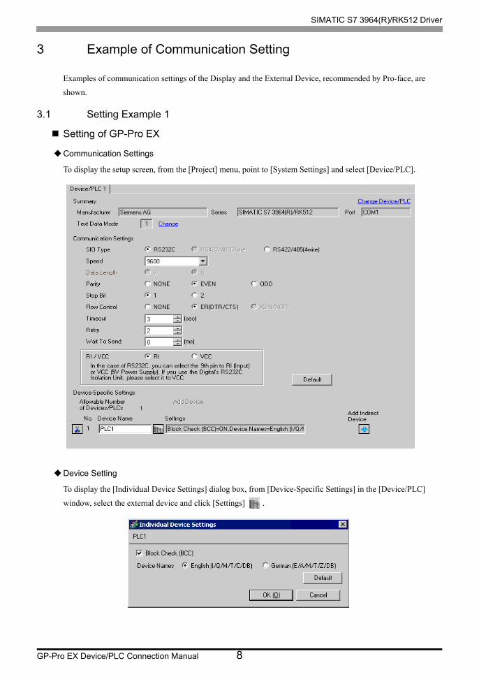
3.1 Setting Example 1
Setting of GP-Pro EX
Communication Settings
To display the setup screen, from the [Project] menu, point to [System Settings] and select [Device/PLC].
Device Setting
To display the [Individual Device Settings] dialog box, from [Device-Specific Settings] in the [Device/PLC]
window, select the external device and click [Settings] .
SIMATIC S7 3964(R)/RK512 Driver
GP-Pro EX Device/PLC Connection Manual 9
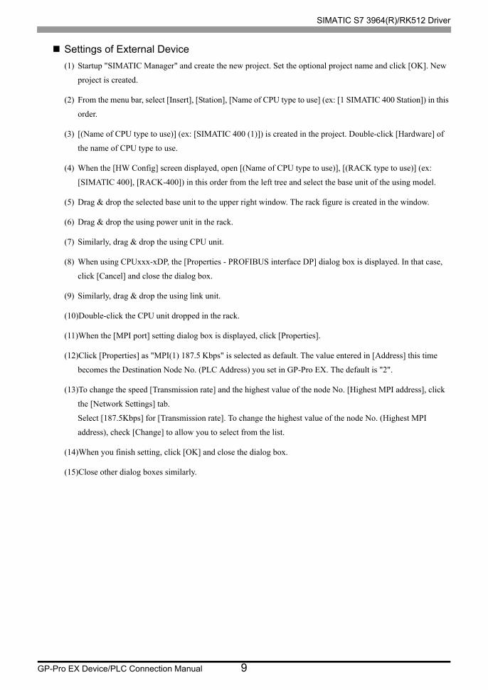
Settings of External Device
(1) Startup "SIMATIC Manager" and create the new project. Set the optional project name and click [OK]. New
project is created.
(2) From the menu bar, select [Insert], [Station], [Name of CPU type to use] (ex: [1 SIMATIC 400 Station]) in this
order.
(3) [(Name of CPU type to use)] (ex: [SIMATIC 400 (1)]) is created in the project. Double-click [Hardware] of
the name of CPU type to use.
(4) When the [HW Config] screen displayed, open [(Name of CPU type to use)], [(RACK type to use)] (ex:
[SIMATIC 400], [RACK-400]) in this order from the left tree and select the base unit of the using model.
(5) Drag & drop the selected base unit to the upper right window. The rack figure is created in the window.
(6) Drag & drop the using power unit in the rack.
(7) Similarly, drag & drop the using CPU unit.
(8) When using CPUxxx-xDP, the [Properties - PROFIBUS interface DP] dialog box is displayed. In that case,
click [Cancel] and close the dialog box.
(9) Similarly, drag & drop the using link unit.
(10)Double-click the CPU unit dropped in the rack.
(11)When the [MPI port] setting dialog box is displayed, click [Properties].
(12)Click [Properties] as "MPI(1) 187.5 Kbps" is selected as default. The value entered in [Address] this time
becomes the Destination Node No. (PLC Address) you set in GP-Pro EX. The default is "2".
(13)To change the speed [Transmission rate] and the highest value of the node No. [Highest MPI address], click
the [Network Settings] tab.
Select [187.5Kbps] for [Transmission rate]. To change the highest value of the node No. (Highest MPI
address), check [Change] to allow you to select from the list.
(14)When you finish setting, click [OK] and close the dialog box.
(15)Close other dialog boxes similarly.
SIMATIC S7 3964(R)/RK512 Driver
GP-Pro EX Device/PLC Connection Manual 10
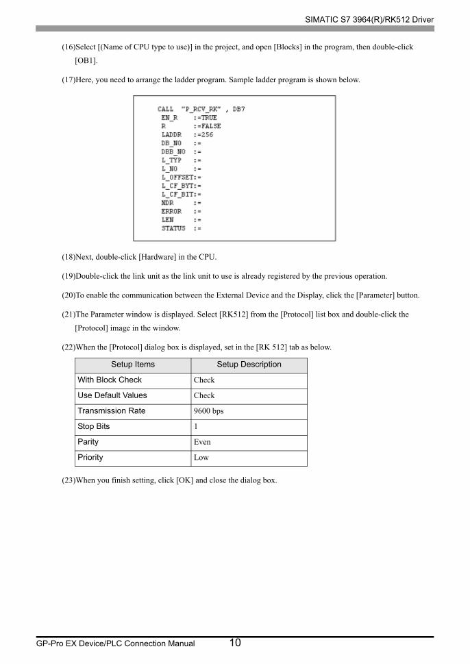
(16)Select [(Name of CPU type to use)] in the project, and open [Blocks] in the program, then double-click
[OB1].
(17)Here, you need to arrange the ladder program. Sample ladder program is shown below.
(18)Next, double-click [Hardware] in the CPU.
(19)Double-click the link unit as the link unit to use is already registered by the previous operation.
(20)To enable the communication between the External Device and the Display, click the [Parameter] button.
(21)The Parameter window is displayed. Select [RK512] from the [Protocol] list box and double-click the
[Protocol] image in the window.
(22)When the [Protocol] dialog box is displayed, set in the [RK 512] tab as below.
(23)When you finish setting, click [OK] and close the dialog box.
Setup Items Setup Description
With Block Check Check
Use Default Values Check
Transmission Rate 9600 bps
Stop Bits 1
Parity Even
Priority Low
SIMATIC S7 3964(R)/RK512 Driver
GP-Pro EX Device/PLC Connection Manual 11
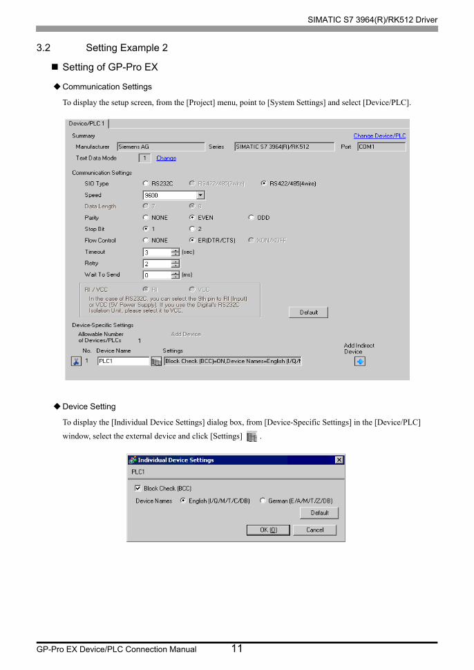
3.2 Setting Example 2
Setting of GP-Pro EX
Communication Settings
To display the setup screen, from the [Project] menu, point to [System Settings] and select [Device/PLC].
Device Setting
To display the [Individual Device Settings] dialog box, from [Device-Specific Settings] in the [Device/PLC]
window, select the external device and click [Settings] .
SIMATIC S7 3964(R)/RK512 Driver
GP-Pro EX Device/PLC Connection Manual 12
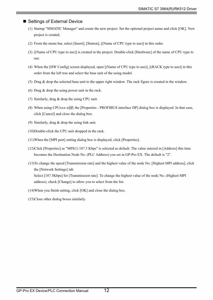
Settings of External Device
(1) Startup "SIMATIC Manager" and create the new project. Set the optional project name and click [OK]. New
project is created.
(2) From the menu bar, select [Insert], [Station], [(Name of CPU type to use)] in this order.
(3) [(Name of CPU type to use)] is created in the project. Double-click [Hardware] of the name of CPU type to
use.
(4) When the [HW Config] screen displayed, open [(Name of CPU type to use)], [(RACK type to use)] in this
order from the left tree and select the base unit of the using model.
(5) Drag & drop the selected base unit to the upper right window. The rack figure is created in the window.
(6) Drag & drop the using power unit in the rack.
(7) Similarly, drag & drop the using CPU unit.
(8) When using CPUxxx-xDP, the [Properties - PROFIBUS interface DP] dialog box is displayed. In that case,
click [Cancel] and close the dialog box.
(9) Similarly, drag & drop the using link unit.
(10)Double-click the CPU unit dropped in the rack.
(11)When the [MPI port] setting dialog box is displayed, click [Properties].
(12)Click [Properties] as "MPI(1) 187.5 Kbps" is selected as default. The value entered in [Address] this time
becomes the Destination Node No. (PLC Address) you set in GP-Pro EX. The default is "2".
(13)To change the speed [Transmission rate] and the highest value of the node No. [Highest MPI address], click
the [Network Settings] tab.
Select [187.5Kbps] for [Transmission rate]. To change the highest value of the node No. (Highest MPI
address), check [Change] to allow you to select from the list.
(14)When you finish setting, click [OK] and close the dialog box.
(15)Close other dialog boxes similarly.
SIMATIC S7 3964(R)/RK512 Driver
GP-Pro EX Device/PLC Connection Manual 13
(16)Select [(Name of CPU type to use)] in the project, and open [Blocks] in the program, then double-click
[OB1].
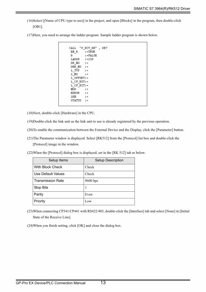
(17)Here, you need to arrange the ladder program. Sample ladder program is shown below.
(18)Next, double-click [Hardware] in the CPU.
(19)Double-click the link unit as the link unit to use is already registered by the previous operation.
(20)To enable the communication between the External Device and the Display, click the [Parameter] button.
(21)The Parameter window is displayed. Select [RK512] from the [Protocol] list box and double-click the
[Protocol] image in the window.
(22)When the [Protocol] dialog box is displayed, set in the [RK 512] tab as below.
(23)When connecting CP341/CP441 with RS422/485, double-click the [Interface] tab and select [None] in [Initial
State of the Receive Line].
(24)When you finish setting, click [OK] and close the dialog box.
Setup Items Setup Description
With Block Check Check
Use Default Values Check
Transmission Rate 9600 bps
Stop Bits 1
Parity Even
Priority Low
SIMATIC S7 3964(R)/RK512 Driver
GP-Pro EX Device/PLC Connection Manual 14
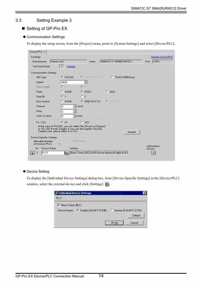
3.3 Setting Example 3
Setting of GP-Pro EX
Communication Settings
To display the setup screen, from the [Project] menu, point to [System Settings] and select [Device/PLC].
Device Setting
To display the [Individual Device Settings] dialog box, from [Device-Specific Settings] in the [Device/PLC]
window, select the external device and click [Settings] .
SIMATIC S7 3964(R)/RK512 Driver
GP-Pro EX Device/PLC Connection Manual 15
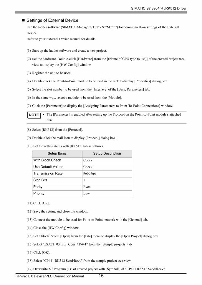
Settings of External Device
Use the ladder software (SIMATIC Manager STEP 7 S7/M7/C7) for communication settings of the External
Device.
Refer to your External Device manual for details.
(1) Start up the ladder software and create a new project.
(2) Set the hardware. Double-click [Hardware] from the [(Name of CPU type to use)] of the created project tree
view to display the [HW Config] window.
(3) Register the unit to be used.
(4) Double-click the Point-to-Point module to be used in the rack to display [Properties] dialog box.
(5) Select the slot number to be used from the [Interface] of the [Basic Parameters] tab.
(6) In the same way, select a module to be used from the [Module].
(7) Click the [Parameter] to display the [Assigning Parameters to Point-To-Point Connections] window.
(8) Select [RK512] from the [Protocol].
(9) Double-click the mail icon to display [Protocol] dialog box.
(10) Set the setting items with [RK512] tab as follows.
(11) Click [OK].
(12) Save the setting and close the window.
(13) Connect the module to be used for Point-to-Point network with the [General] tab.
(14) Close the [HW Config] window.
(15) Set a block. Select [Open] from the [File] menu to display the [Open Project] dialog box.
(16) Select "zXX21_03_PtP_Com_CP441" from the [Sample projects] tab.
(17) Click [OK].
(18) Select "CP441 RK512 Send/Recv" from the sample project tree view.
(19) Overwrite"S7 Program (1)" of created project with [Symbols] of "CP441 RK512 Send/Recv".
• The [Parameter] is enabled after setting up the Protocol on the Point-to-Point module's attached
disk.
Setup Items Setup Description
With Block Check Check
Use Default Values Check
Transmission Rate 9600 bps
Stop Bits 1
Parity Even
Priority Low
SIMATIC S7 3964(R)/RK512 Driver
GP-Pro EX Device/PLC Connection Manual 16
(20) In the same way, overwrite [Blocks] of the project created except for [System Data] from the [Blocks].
(21) Double-click [OB1] from the [Blocks] of created project tree view to display the [LAD/STL/FBD] window.
(22) Delete the line of "UC"SEND"//Call of FC for execution BSEND-Jobs" of Network 1.
(23) Save the setting and close the window.
(24) Set Network Configuration. Select [(CPU name in use)] from the created project.
(25) Double-click [Connections] in the project window to start up NetPro.
(26) Right-click the CPU to be used from the created project on NetPro.
(27) Select [Insert New Connection] to display the [Insert New Connection] dialog box.
(28) Select [Unspecified] from the created project of [Connection Partner] tree view.
(29) Select [Point-to-point connection] from the [Type] of [Connection].
(30) Click [OK] to display the [Properties -PtP connection] dialog box.
(31) Click [OK].
(32) Confirm that Point-to-Point connection is displayed in the [Local ID] as "1000".
(33) Select [Exit] from the [Network] menu to close the window.
(34) Download the hardware setting and Blocks setting to the Extended Device.
(35) Download the network configuration setting to the Extended Device.

SIMATIC S7 3964(R)/RK512 Driver
GP-Pro EX Device/PLC Connection Manual 17
3.4 Setting Example 4
Setting of GP-Pro EX
Communication Settings
To display the setup screen, from the [Project] menu, point to [System Settings] and select [Device/PLC].
Device Setting
To display the [Individual Device Settings] dialog box, from [Device-Specific Settings] in the [Device/PLC]
window, select the external device and click [Settings] .

SIMATIC S7 3964(R)/RK512 Driver
GP-Pro EX Device/PLC Connection Manual 18
Settings of External Device
Use the ladder software (SIMATIC Manager STEP 7 S7/M7/C7) for communication settings of the External
Device.
Refer to your External Device manual for details.
(1) Start up the ladder software and create a new project.
(2) Set the hardware. Double-click [Hardware] from the [(Name of CPU type to use)] of the created project tree
view to display the [HW Config] window.
(3) Register the unit to be used.
(4) Double-click the Point-to-Point module to be used in the rack to display [Properties] dialog box.
(5) Select the slot number to be used from the [Interface] of the [Basic Parameters] tab.
(6) In the same way, select a module to be used from the [Module].
(7) Click the [Parameter] to display the [Assigning Parameters to Point-To-Point Connections] window.
(8) Select [RK512] from the [Protocol].
(9) Double-click the mail icon to display [Protocol] dialog box.
(10) Set the setting items with [RK512] tab as follows.
(11) Click [OK].
(12) Save the setting and close the window.
(13) Connect the module to be used for Point-to-Point network with the [General] tab.
(14) Close the [HW Config] window.
(15) Set a block. Select [Open] from the [File] menu to display the [Open Project] dialog box.
(16) Select "zXX21_03_PtP_Com_CP441" from the [Sample projects] tab.
(17) Click [OK].
(18) Select "CP441 RK512 Send/Recv" from the sample project tree view.
(19) Overwrite"S7 Program (1)" of created project with [Symbols] of "CP441 RK512 Send/Recv".
• The [Parameter] is enabled after setting up the Protocol on the Point-to-Point module's attached
disk.
Setup Items Setup Description
With Block Check Check
Use Default Values Check
Transmission Rate 9600 bps
Stop Bits 1
Parity Even
Priority Low

SIMATIC S7 3964(R)/RK512 Driver
GP-Pro EX Device/PLC Connection Manual 19
(20) In the same way, overwrite [Blocks] of the project created except for [System Data] from the [Blocks].
(21) Double-click [OB1] from the [Blocks] of created project tree view to display the [LAD/STL/FBD] window.
(22) Delete the line of "UC"SEND"//Call of FC for execution BSEND-Jobs" of Network 1.
(23) Save the setting and close the window.
(24) Set Network Configuration. Select [(CPU name in use)] from the created project.
(25) Double-click [Connections] in the project window to start up NetPro.
(26) Right-click the CPU to be used from the created project on NetPro.
(27) Select [Insert New Connection] to display the [Insert New Connection] dialog box.
(28) Select [Unspecified] from the created project of [Connection Partner] tree view.
(29) Select [Point-to-point connection] from the [Type] of [Connection].
(30) Click [OK] to display the [Properties -PtP connection] dialog box.
(31) Click [OK].
(32) Confirm that Point-to-Point connection is displayed in the [Local ID] as "1000".
(33) Select [Exit] from the [Network] menu to close the window.
(34) Download the hardware setting and Blocks setting to the Extended Device.
(35) Download the network configuration setting to the Extended Device.
SIMATIC S7 3964(R)/RK512 Driver
GP-Pro EX Device/PLC Connection Manual 20
4 Setup Items
Set communication settings of the Display with GP-Pro EX or in offline mode of the Display.
The setting of each parameter must be identical to that of External Device.
"3 Example of Communication Setting" (page 8)
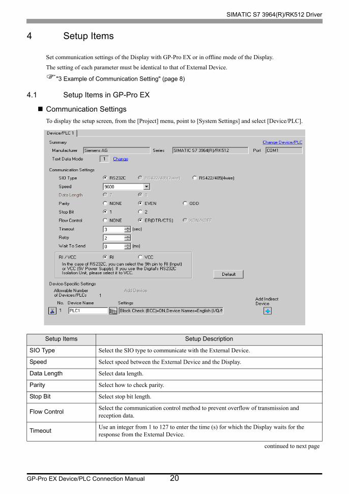
4.1 Setup Items in GP-Pro EX
Communication Settings
To display the setup screen, from the [Project] menu, point to [System Settings] and select [Device/PLC].
Setup Items Setup Description
SIO Type Select the SIO type to communicate with the External Device.
Speed Select speed between the External Device and the Display.
Data Length Select data length.
Parity Select how to check parity.
Stop Bit Select stop bit length.
Flow ControlSelect the communication control method to prevent overflow of transmission and reception data.
TimeoutUse an integer from 1 to 127 to enter the time (s) for which the Display waits for the response from the External Device.
continued to next page
SIMATIC S7 3964(R)/RK512 Driver
GP-Pro EX Device/PLC Connection Manual 21
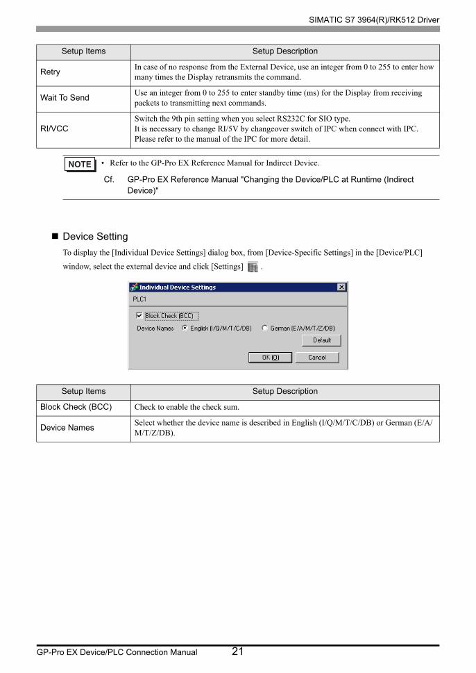
Device Setting
To display the [Individual Device Settings] dialog box, from [Device-Specific Settings] in the [Device/PLC]
window, select the external device and click [Settings] .
RetryIn case of no response from the External Device, use an integer from 0 to 255 to enter how many times the Display retransmits the command.
Wait To SendUse an integer from 0 to 255 to enter standby time (ms) for the Display from receiving packets to transmitting next commands.
RI/VCCSwitch the 9th pin setting when you select RS232C for SIO type.It is necessary to change RI/5V by changeover switch of IPC when connect with IPC. Please refer to the manual of the IPC for more detail.
• Refer to the GP-Pro EX Reference Manual for Indirect Device.
Cf. GP-Pro EX Reference Manual "Changing the Device/PLC at Runtime (Indirect Device)"
Setup Items Setup Description
Block Check (BCC) Check to enable the check sum.
Device NamesSelect whether the device name is described in English (I/Q/M/T/C/DB) or German (E/A/M/T/Z/DB).
Setup Items Setup Description
SIMATIC S7 3964(R)/RK512 Driver
GP-Pro EX Device/PLC Connection Manual 22
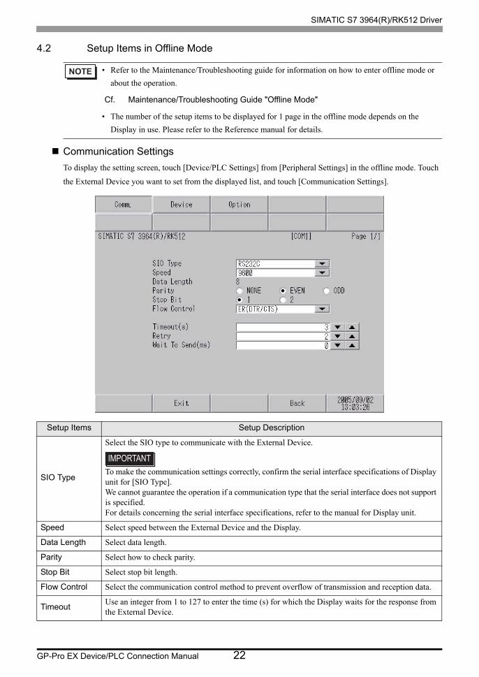
4.2 Setup Items in Offline Mode
Communication Settings
To display the setting screen, touch [Device/PLC Settings] from [Peripheral Settings] in the offline mode. Touch
the External Device you want to set from the displayed list, and touch [Communication Settings].
• Refer to the Maintenance/Troubleshooting guide for information on how to enter offline mode or
about the operation.
Cf. Maintenance/Troubleshooting Guide "Offline Mode"
• The number of the setup items to be displayed for 1 page in the offline mode depends on the
Display in use. Please refer to the Reference manual for details.
Setup Items Setup Description
SIO Type
Select the SIO type to communicate with the External Device.
To make the communication settings correctly, confirm the serial interface specifications of Display unit for [SIO Type].We cannot guarantee the operation if a communication type that the serial interface does not support is specified.For details concerning the serial interface specifications, refer to the manual for Display unit.
Speed Select speed between the External Device and the Display.
Data Length Select data length.
Parity Select how to check parity.
Stop Bit Select stop bit length.
Flow Control Select the communication control method to prevent overflow of transmission and reception data.
TimeoutUse an integer from 1 to 127 to enter the time (s) for which the Display waits for the response from the External Device.
SIMATIC S7 3964(R)/RK512 Driver
GP-Pro EX Device/PLC Connection Manual 23
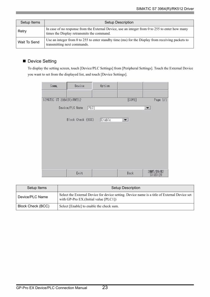
Device Setting
To display the setting screen, touch [Device/PLC Settings] from [Peripheral Settings]. Touch the External Device
you want to set from the displayed list, and touch [Device Settings].
RetryIn case of no response from the External Device, use an integer from 0 to 255 to enter how many times the Display retransmits the command.
Wait To SendUse an integer from 0 to 255 to enter standby time (ms) for the Display from receiving packets to transmitting next commands.
Setup Items Setup Description
Device/PLC NameSelect the External Device for device setting. Device name is a title of External Device set with GP-Pro EX.(Initial value [PLC1])
Block Check (BCC) Select [Enable] to enable the check sum.
Setup Items Setup Description
SIMATIC S7 3964(R)/RK512 Driver
GP-Pro EX Device/PLC Connection Manual 24
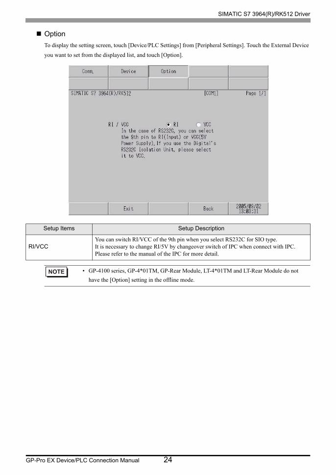
Option
To display the setting screen, touch [Device/PLC Settings] from [Peripheral Settings]. Touch the External Device
you want to set from the displayed list, and touch [Option].
Setup Items Setup Description
RI/VCCYou can switch RI/VCC of the 9th pin when you select RS232C for SIO type.It is necessary to change RI/5V by changeover switch of IPC when connect with IPC. Please refer to the manual of the IPC for more detail.
• GP-4100 series, GP-4*01TM, GP-Rear Module, LT-4*01TM and LT-Rear Module do not
have the [Option] setting in the offline mode.

SIMATIC S7 3964(R)/RK512 Driver
GP-Pro EX Device/PLC Connection Manual 25
5 Cable Diagram
The cable diagram shown below may be different from the cable diagram recommended by Siemens AG. Please
be assured there is no operational problem in applying the cable diagram shown in this manual.
• The FG pin of the main body of the External Device must be D-class grounded. Please refer to the manual of
the External Device for more details.
• SG and FG are connected inside the Display. When connecting SG to the External Device, design the system
not to form short-circuit loop.
• Connect the isolation unit, when communication is not stabilized under the influence of a noise etc..
Cable Diagram 1
1A)
Display
(Connection Port)Cable Remarks
GP3000 (COM1)GP4000*1 (COM1)SP5000*2 (COM1/2)SP-5B00 (COM1)ST (COM1)LT3000 (COM1)IPC*3
PC/AT
*1 All GP4000 models except GP-4100 Series and GP-4203T
*2 Except SP-5B00
*3 Only the COM port which can communicate by RS-232C can be used.
IPC COM Port (page 4)
1A User-created cableThe cable length must be 15m or less.
GP-4105 (COM1)GP-4115T (COM1) GP-4115T3 (COM1)
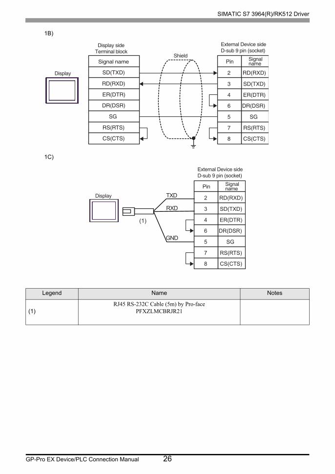
1B User-created cableThe cable length must be 15m or less.
LT-4*01TM (COM1)LT-Rear Module (COM1) 1C
RJ45 RS-232C Cable (5m) by Pro-facePFXZLMCBRJR21
The cable length must be 5m or less.
SG
RS(RTS)
5
7
CS(CTS)8
RD(RXD)2
SD(TXD)3
ER(DTR)4
DR(DSR)6
SG
RS(RTS)
5
7
CS(CTS)8
SD(TXD)3
RD(RXD)2
ER(DTR)4
DR(DSR)6
Display
D-sub 9 pin (socket)External Device sideD-sub 9 pin (socket)
ShieldPin Signal
name Pin Signalname
Display side
SIMATIC S7 3964(R)/RK512 Driver
GP-Pro EX Device/PLC Connection Manual 26
1B)
1C)
Legend Name Notes
(1)RJ45 RS-232C Cable (5m) by Pro-face
PFXZLMCBRJR21
SG
RS(RTS)
CS(CTS)
RD(RXD)
SD(TXD)
ER(DTR)
DR(DSR)
SG
RS(RTS)
5
7
CS(CTS)8
SD(TXD)3
RD(RXD)2
ER(DTR)4
DR(DSR)6
Display
Display side Terminal block
External Device sideD-sub 9 pin (socket)
ShieldSignal name Pin Signal
name
SG
RS(RTS)
5
7
CS(CTS)8
SD(TXD)3
RD(RXD)2
ER(DTR)4
DR(DSR)6
Display
External Device sideD-sub 9 pin (socket)
Pin Signalname
GND
TXD
RXD
(1)
SIMATIC S7 3964(R)/RK512 Driver
GP-Pro EX Device/PLC Connection Manual 27
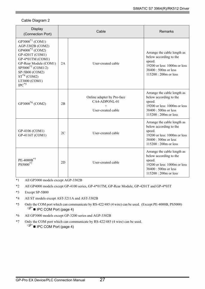
Cable Diagram 2
Display
(Connection Port)Cable Remarks
GP3000*1 (COM1)AGP-3302B (COM2)GP4000*2 (COM2)GP-4201T (COM1)GP-4*01TM (COM1)GP-Rear Module (COM1)SP5000*3 (COM1/2)SP-5B00 (COM2)ST*4 (COM2)LT3000 (COM1)IPC*5
*1 All GP3000 models except AGP-3302B
*2 All GP4000 models except GP-4100 series, GP-4*01TM, GP-Rear Module, GP-4201T and GP-4*03T
*3 Except SP-5B00
*4 All ST models except AST-3211A and AST-3302B
*5 Only the COM port which can communicate by RS-422/485 (4 wire) can be used. (Except PE-4000B, PS5000)
IPC COM Port (page 4)
2A User-created cable
Arrange the cable length as below according to the speed.19200 or less: 1000m or less38400 : 500m or less115200 : 200m or less
GP3000*6 (COM2)
*6 All GP3000 models except GP-3200 series and AGP-3302B
2B
Online adapter by Pro-faceCA4-ADPONL-01
+User-created cable
Arrange the cable length as below according to the speed.19200 or less: 1000m or less38400 : 500m or less115200 : 200m or less
GP-4106 (COM1)GP-4116T (COM1)
2C User-created cable
Arrange the cable length as below according to the speed.19200 or less: 1000m or less38400 : 500m or less115200 : 200m or less
PE-4000B*7
PS5000*7
*7 Only the COM port which can communicate by RS-422/485 (4 wire) can be used.
IPC COM Port (page 4)
2D User-created cable
Arrange the cable length as below according to the speed.19200 or less: 1000m or less38400 : 500m or less115200 : 200m or less
SIMATIC S7 3964(R)/RK512 Driver
GP-Pro EX Device/PLC Connection Manual 28
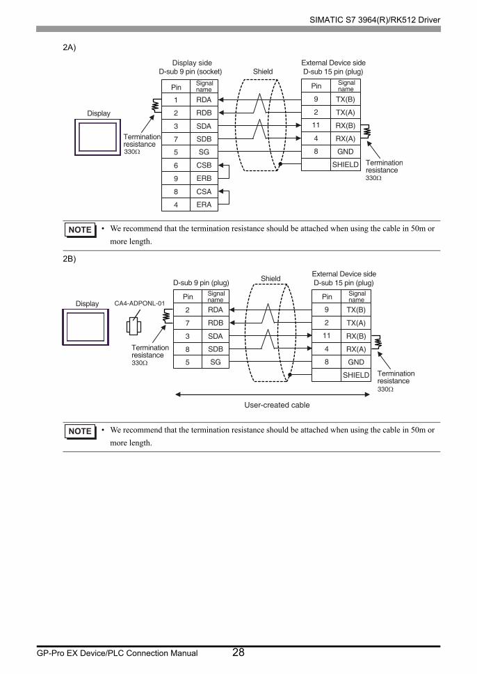
2A)
2B)
• We recommend that the termination resistance should be attached when using the cable in 50m or
more length.
• We recommend that the termination resistance should be attached when using the cable in 50m or
more length.
9
2
11
4
8
TX(B)
RX(B)
RX(A)
TX(A)
GND
SHIELD
1
2
3
7
5 SG
RDA
SDA
SDB
RDB
6
9
8
4
CSB
CSA
ERA
ERB
Pin SignalnamePin
Signalname
Display
D-sub 9 pin (socket)External Device side D-sub 15 pin (plug)Shield
Terminationresistance
Terminationresistance
330Ω
330Ω
Display side
SG
9
2
11
4
8
CA4-ADPONL-019
2
11
4
8
TX(B)
RX(B)
RX(A)
TX(A)
GND
SHIELD
2
7
3
8
5 SG
RDA
SDA
SDB
RDB
Display
D-sub 9 pin (plug)External Device side D-sub 15 pin (plug)Shield
Terminationresistance
Terminationresistance
Pin Signalname Pin Signal
name
User-created cable
330Ω
330Ω
SIMATIC S7 3964(R)/RK512 Driver
GP-Pro EX Device/PLC Connection Manual 29
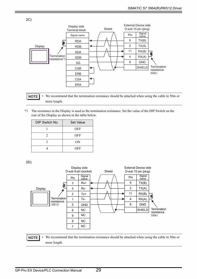
2C)
*1 The resistance in the Display is used as the termination resistance. Set the value of the DIP Switch on the rear of the Display as shown in the table below.
2D)
• We recommend that the termination resistance should be attached when using the cable in 50m or
more length.
DIP Switch No. Set Value
1 OFF
2 OFF
3 ON
4 OFF
• We recommend that the termination resistance should be attached when using the cable in 50m or
more length.
9
2
11
4
8
TX(B)
RX(B)
RX(A)
TX(A)
GND
SHIELDSG
RDA
SDA
SDB
RDB
CSB
CSA
ERA
ERB
Pin SignalnameSignal name
Display
Display side Terminal block
External Device side D-sub 15 pin (plug)Shield
Terminationresistance*1
Terminationresistance330Ω
9
2
11
4
8
TX(B)
RX(B)
RX(A)
TX(A)
GND
SHIELD
3
4
2
1
5
Rx-
Rx+
Tx+
Tx-
GND
NC
NC
NC
NC
6
9
8
7
Pin SignalnamePin
Signalname
Display
D-sub 9 pin (socket)External Device side D-sub 15 pin (plug)Shield
Terminationresistance
Terminationresistance
330 Ω
330Ω
Display side
SIMATIC S7 3964(R)/RK512 Driver
GP-Pro EX Device/PLC Connection Manual 30
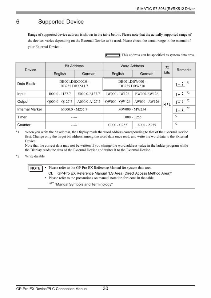
6 Supported Device
Range of supported device address is shown in the table below. Please note that the actually supported range of
the devices varies depending on the External Device to be used. Please check the actual range in the manual of
your External Device.
This address can be specified as system data area.
DeviceBit Address Word Address 32
bitsRemarks
English German English German
Data BlockDB001.DBX000.0 - DB255.DBX511.7
DB001.DBW000 - DB255.DBW510
*1
*1 When you write the bit address, the Display reads the word address corresponding to that of the External Device first. Change only the target bit address among the word data once read, and write the word data to the External Device.Note that the correct data may not be written if you change the word address value in the ladder program while the Display reads the data of the External Device and writes it to the External Device.
Input I000.0 - I127.7 E000.0-E127.7 IW000 - IW126 EW000-EW126 *2
*2 Write disable
Output Q000.0 - Q127.7 A000.0-A127.7 QW000 - QW126 AW000 - AW126 *2
Internal Marker M000.0 - M255.7 MW000 - MW254 *2
Timer ----- T000 - T255 *2
Counter ----- C000 - C255 Z000 - Z255 *2
• Please refer to the GP-Pro EX Reference Manual for system data area.
Cf. GP-Pro EX Reference Manual "LS Area (Direct Access Method Area)"• Please refer to the precautions on manual notation for icons in the table.
"Manual Symbols and Terminology"
SIMATIC S7 3964(R)/RK512 Driver
GP-Pro EX Device/PLC Connection Manual 31
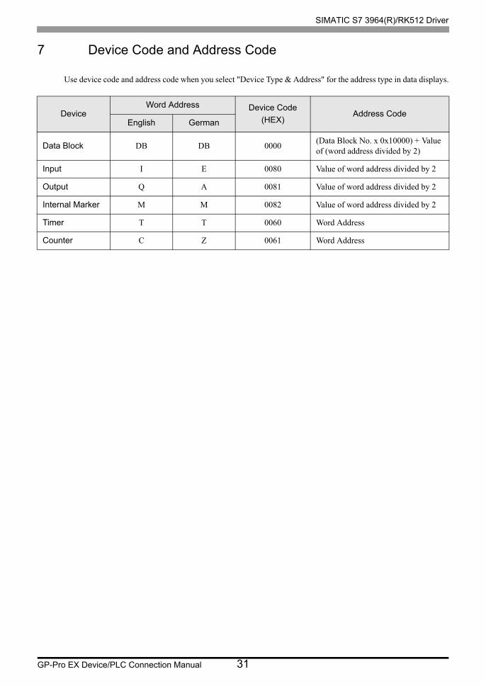
7 Device Code and Address Code
Use device code and address code when you select "Device Type & Address" for the address type in data displays.
DeviceWord Address Device Code
(HEX)Address Code
English German
Data Block DB DB 0000(Data Block No. x 0x10000) + Value of (word address divided by 2)
Input I E 0080 Value of word address divided by 2
Output Q A 0081 Value of word address divided by 2
Internal Marker M M 0082 Value of word address divided by 2
Timer T T 0060 Word Address
Counter C Z 0061 Word Address
SIMATIC S7 3964(R)/RK512 Driver
GP-Pro EX Device/PLC Connection Manual 32
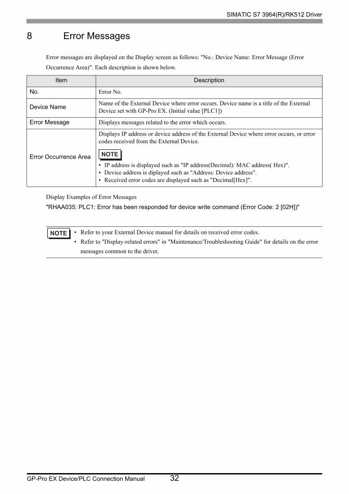
8 Error Messages
Error messages are displayed on the Display screen as follows: "No.: Device Name: Error Message (Error
Occurrence Area)". Each description is shown below.
Display Examples of Error Messages
"RHAA035: PLC1: Error has been responded for device write command (Error Code: 2 [02H])"
Item Description
No. Error No.
Device NameName of the External Device where error occurs. Device name is a title of the External Device set with GP-Pro EX. (Initial value [PLC1])
Error Message Displays messages related to the error which occurs.
Error Occurrence Area
Displays IP address or device address of the External Device where error occurs, or error codes received from the External Device.
• IP address is displayed such as "IP address(Decimal): MAC address( Hex)".• Device address is diplayed such as "Address: Device address".• Received error codes are displayed such as "Decimal[Hex]".
• Refer to your External Device manual for details on received error codes.
• Refer to "Display-related errors" in "Maintenance/Troubleshooting Guide" for details on the error
messages common to the driver.