simaris project tutorial · simaris project allows to create a quick overview of the space...
TRANSCRIPT
SIMARIS project Tutorial Software for determining the space requirements
and budget for electric power distribution
SIMARIS project
1 Introduction
2 Getting Started
3 Project Definition and System Planning
4 Budget
5 Project Output
6 More about SIMARIS
Page 2
Software for determining the space requirements and budget for electric power distribution
1 2 3 4 5 6 Start SIMARIS project
SIMARIS project Tutorial
1 Introduction
2 Getting Started
3 Project Definition and System Planning
4 Budget
5 Project Output
6 More about SIMARIS
SIMARIS Planning tools SIMARIS project
1 Introduction
Unrestricted © Siemens AG 2015 All rights reserved.
November 2015 Page 3 SIMARIS project 1 2 3 4 5 6 Start
SIMARIS planning tools
The SIMARIS planning tools provide efficient support in dimensioning an electric power distribution system and determining the equipment and distribution boards for it. • SIMARIS design for network calculation and dimensioning • SIMARIS project for determining the space requirements of distribution boards and the budget, and
for generating specifications (bills of quantities) • SIMARIS curves to display tripping characteristics, as well as cut-off current characteristics and let-
through energy curves
The advantages of SIMARIS planning tools: • Intuitive and easy handling with user-friendly documentation options for the planning results • End-to-end planning for all devices and systems from the medium-voltage level to the power
consumer • Automatic selection of matching components and distribution board systems • High degree of planning reliability plus flexibility in the planning and implementation process
1. Introduction
Unrestricted © Siemens AG 2015 All rights reserved.
November 2015 Page 4 SIMARIS project 1 2 3 4 5 6 Start
SIMARIS project
SIMARIS project allows to create a quick overview of the space requirements and budget for power distribution inside buildings that covers medium-voltage switchgear, transformers, low-voltage switchboards and busbar trunking systems, as well as distribution boards feeding final load circuits. • Automatic system selection and placement based on the parameters that were entered • Consideration of functional endurance for busbar systems for power transmission (BD2, LD, LX) • Convenient output options for project documentation, e.g. graphic views and specifications (bills of
quantities) • Easy adaptation of the planning is possible, when things have been defined more precisely. This is
also true in cases where the building's use has been changed or systems were expanded. • Complete plants can be saved as Favourites to be available for future, similar projects • Import of a project created in SIMARIS design for further processing in SIMARIS project
1. Introduction
Page 5
Software for determining the space requirements and budget for electric power distribution
1 2 3 4 5 6 Start SIMARIS project
SIMARIS project Tutorial
1 Introduction
2 Getting Started
3 Project Definition and System Planning
4 Budget
5 Project Output
6 More about SIMARIS
2 Getting Started
Start wizard Workflow
Unrestricted © Siemens AG 2015 All rights reserved.
November 2015 Page 6 SIMARIS project 1 2 3 4 5 6 Start
Start wizard
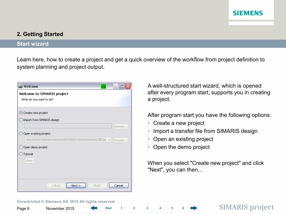
Learn here, how to create a project and get a quick overview of the workflow from project definition to system planning and project output.
A well-structured start wizard, which is opened after every program start, supports you in creating a project. After program start you have the following options: • Create a new project • Import a transfer file from SIMARIS design • Open an existing project • Open the demo project When you select "Create new project" and click "Next", you can then…
2. Getting Started
Unrestricted © Siemens AG 2015 All rights reserved.
November 2015 Page 7 SIMARIS project 1 2 3 4 5 6 Start
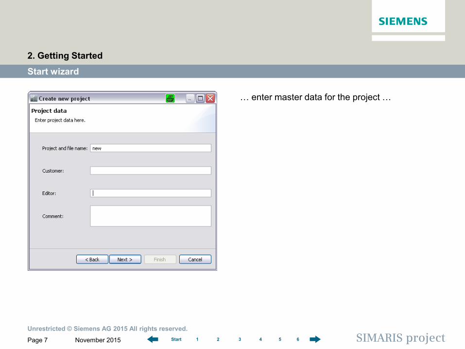
… enter master data for the project …
Start wizard
2. Getting Started

Unrestricted © Siemens AG 2015 All rights reserved.
November 2015 Page 8 SIMARIS project 1 2 3 4 5 6 Start
…decide on a file name and file location for the project…
Start wizard
2. Getting Started
Unrestricted © Siemens AG 2015 All rights reserved.
November 2015 Page 9 SIMARIS project 1 2 3 4 5 6 Start
Start wizard
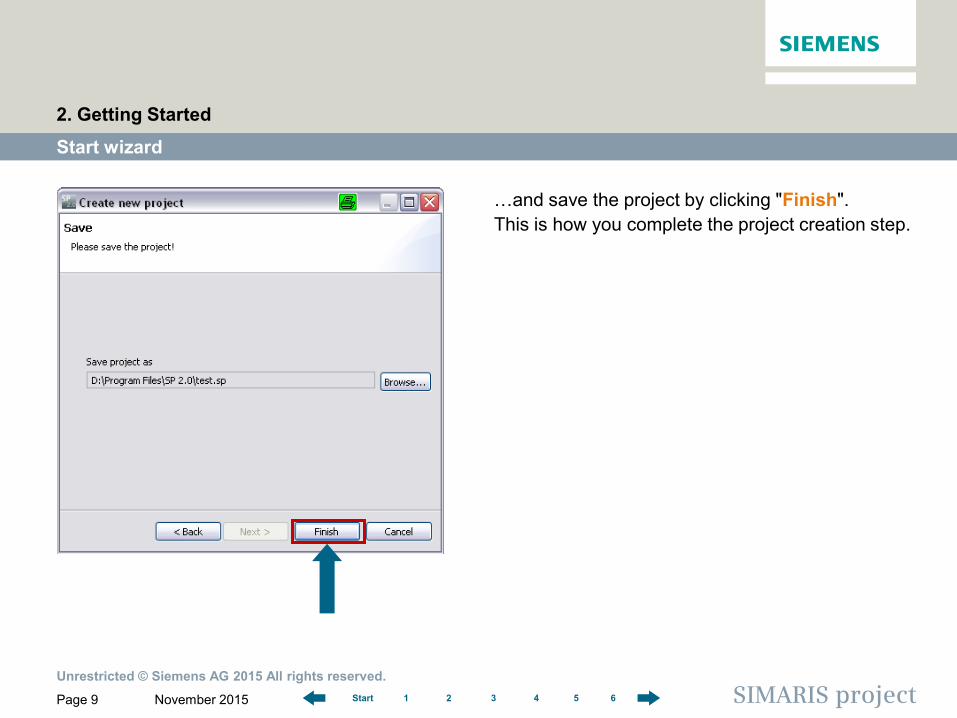
…and save the project by clicking "Finish". This is how you complete the project creation step.
2. Getting Started
Unrestricted © Siemens AG 2015 All rights reserved.
November 2015 Page 10 SIMARIS project 1 2 3 4 5 6 Start
Start wizard
2. Getting Started
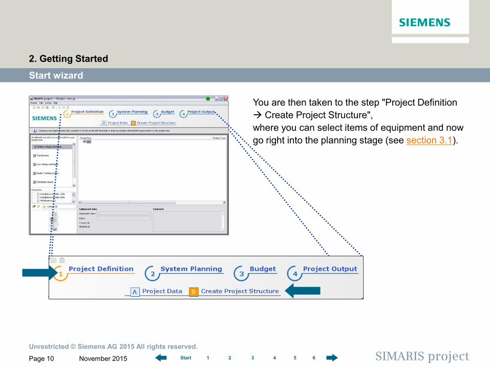
You are then taken to the step "Project Definition Create Project Structure", where you can select items of equipment and now go right into the planning stage (see section 3.1).
Unrestricted © Siemens AG 2015 All rights reserved.
November 2015 Page 11 SIMARIS project 1 2 3 4 5 6 Start
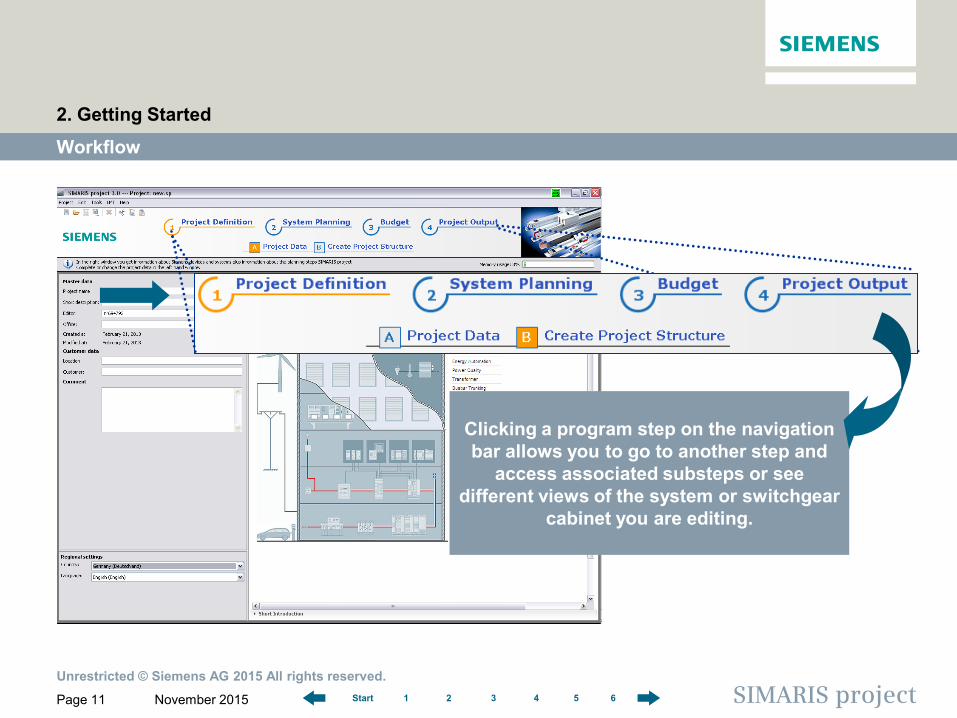
Clicking a program step on the navigation bar allows you to go to another step and
access associated substeps or see different views of the system or switchgear
cabinet you are editing.
Workflow
2. Getting Started
Unrestricted © Siemens AG 2015 All rights reserved.
November 2015 Page 12 SIMARIS project 1 2 3 4 5 6 Start
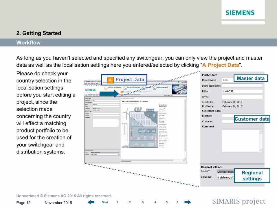
As long as you haven't selected and specified any switchgear, you can only view the project and master data as well as the localisation settings here you entered/selected by clicking "A Project Data".
Workflow
2. Getting Started
Please do check your country selection in the localisation settings before you start editing a project, since the selection made concerning the country will effect a matching product portfolio to be used for the creation of your switchgear and distribution systems.
Master data
Customer data
Regional settings
Unrestricted © Siemens AG 2015 All rights reserved.
November 2015 Page 13 SIMARIS project 1 2 3 4 5 6 Start
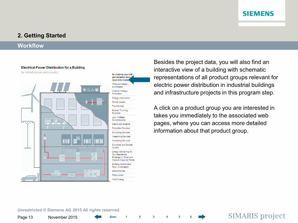
Besides the project data, you will also find an interactive view of a building with schematic representations of all product groups relevant for electric power distribution in industrial buildings and infrastructure projects in this program step. A click on a product group you are interested in takes you immediately to the associated web pages, where you can access more detailed information about that product group.
Workflow
2. Getting Started
Page 14
Software for determining the space requirements and budget for electric power distribution
1 2 3 4 5 6 Start SIMARIS project
SIMARIS project Tutorial
1 Introduction
2 Getting Started
3 Project Definition and System Planning
4 Budget
5 Project Output
6 More about SIMARIS
Transformer
Creating the project structure
Low-voltage switchboard > Master data and system properties > Device list (for distribution board) > Front view
3 Project Definition and System Planning
Busbar trunking system
Tips and tricks for system planning > Copying a system > Favourites library > Project import from SIMARIS design
Unrestricted © Siemens AG 2015 All rights reserved.
November 2015 Page 15 SIMARIS project 1 2 3 4 5 6 Start
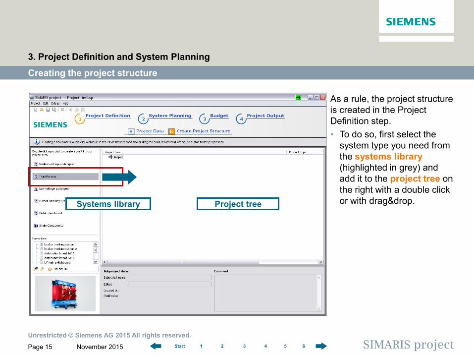
As a rule, the project structure is created in the Project Definition step. • To do so, first select the
system type you need from the systems library (highlighted in grey) and add it to the project tree on the right with a double click or with drag&drop.
Creating the project structure
3. Project Definition and System Planning
Systems library Project tree
Unrestricted © Siemens AG 2015 All rights reserved.
November 2015 Page 16 SIMARIS project 1 2 3 4 5 6 Start
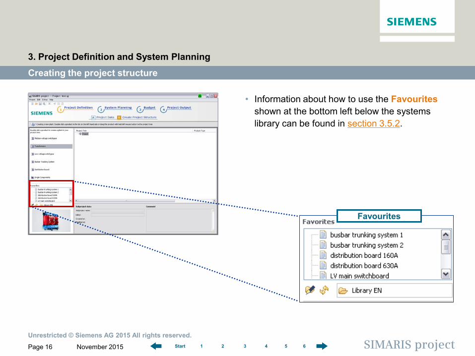
• Information about how to use the Favourites shown at the bottom left below the systems library can be found in section 3.5.2.
Creating the project structure
3. Project Definition and System Planning
Favourites
Unrestricted © Siemens AG 2015 All rights reserved.
November 2015 Page 17 SIMARIS project 1 2 3 4 5 6 Start
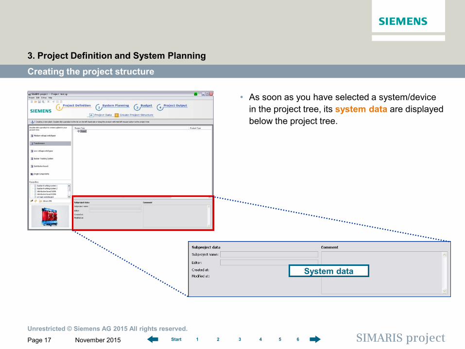
• As soon as you have selected a system/device in the project tree, its system data are displayed below the project tree.
Creating the project structure
3. Project Definition and System Planning
System data
Unrestricted © Siemens AG 2015 All rights reserved.
November 2015 Page 18 SIMARIS project 1 2 3 4 5 6 Start
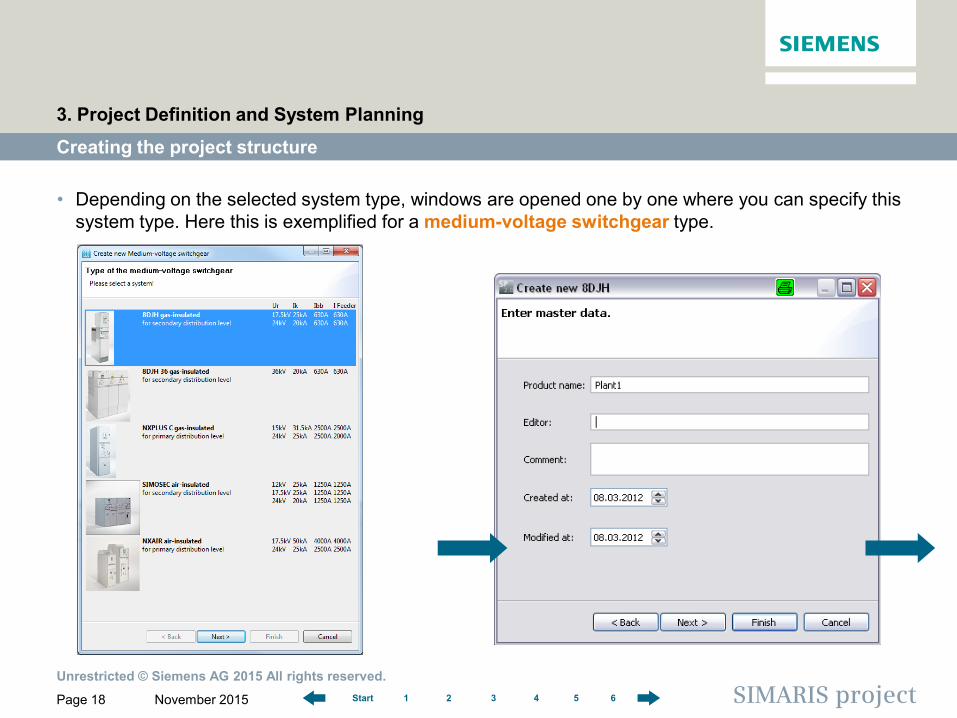
• Depending on the selected system type, windows are opened one by one where you can specify this system type. Here this is exemplified for a medium-voltage switchgear type.
Creating the project structure
3. Project Definition and System Planning
Unrestricted © Siemens AG 2015 All rights reserved.
November 2015 Page 19 SIMARIS project 1 2 3 4 5 6 Start
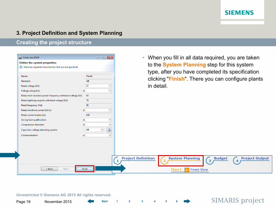
• When you fill in all data required, you are taken to the System Planning step for this system type, after you have completed its specification clicking "Finish". There you can configure plants in detail.
Creating the project structure
3. Project Definition and System Planning
Unrestricted © Siemens AG 2015 All rights reserved.
November 2015 Page 20 SIMARIS project 1 2 3 4 5 6 Start
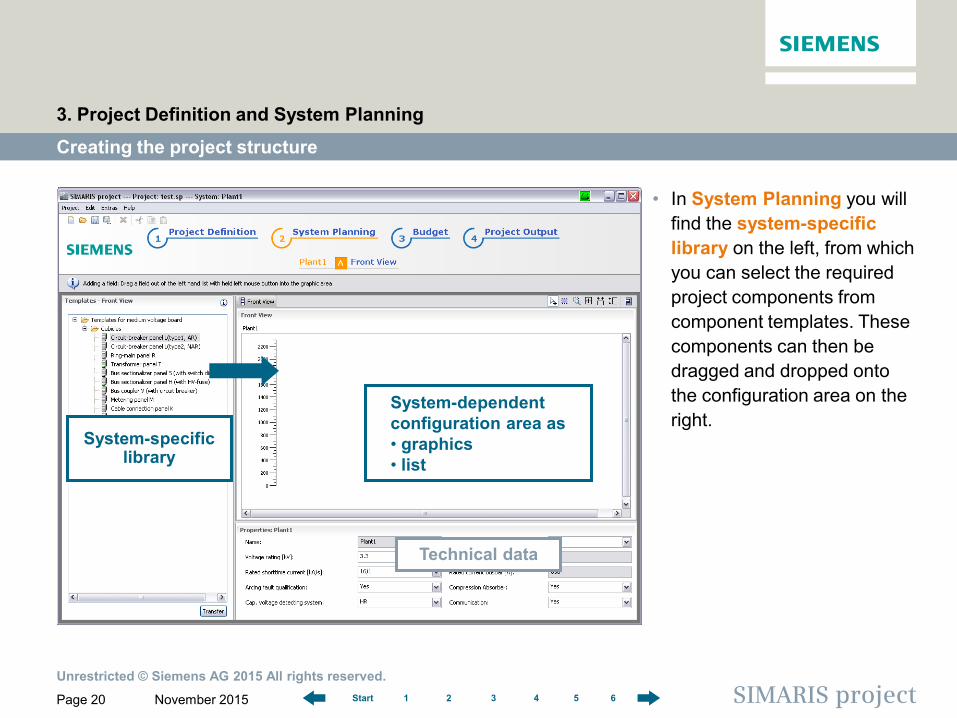
• In System Planning you will find the system-specific library on the left, from which you can select the required project components from component templates. These components can then be dragged and dropped onto the configuration area on the right.
Creating the project structure
3. Project Definition and System Planning
System-specific library
System-dependent configuration area as • graphics • list
Technical data
Unrestricted © Siemens AG 2015 All rights reserved.
November 2015 Page 21 SIMARIS project 1 2 3 4 5 6 Start
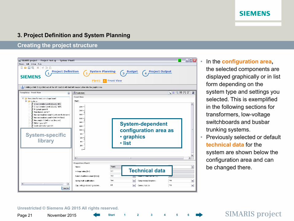
• In the configuration area, the selected components are displayed graphically or in list form depending on the system type and settings you selected. This is exemplified in the following sections for transformers, low-voltage switchboards and busbar trunking systems.
• Previously selected or default technical data for the system are shown below the configuration area and can be changed there.
Creating the project structure
3. Project Definition and System Planning
System-dependent configuration area as • graphics • list
Technical data
System-specific library
Unrestricted © Siemens AG 2015 All rights reserved.
November 2015 Page 22 SIMARIS project 1 2 3 4 5 6 Start
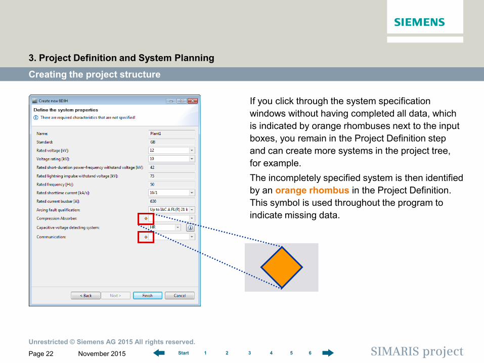
If you click through the system specification windows without having completed all data, which is indicated by orange rhombuses next to the input boxes, you remain in the Project Definition step and can create more systems in the project tree, for example. The incompletely specified system is then identified by an orange rhombus in the Project Definition. This symbol is used throughout the program to indicate missing data.
Creating the project structure
3. Project Definition and System Planning
Unrestricted © Siemens AG 2015 All rights reserved.
November 2015 Page 23 SIMARIS project 1 2 3 4 5 6 Start
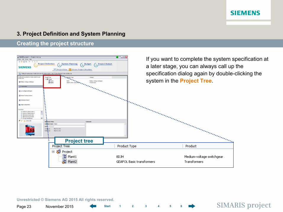
If you want to complete the system specification at a later stage, you can always call up the specification dialog again by double-clicking the system in the Project Tree.
Creating the project structure
3. Project Definition and System Planning
Project tree
Unrestricted © Siemens AG 2015 All rights reserved.
November 2015 Page 24 SIMARIS project 1 2 3 4 5 6 Start
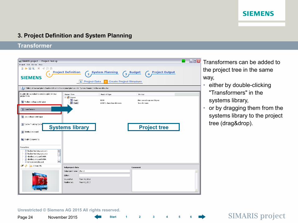
Transformers can be added to the project tree in the same way, • either by double-clicking
"Transformers" in the systems library,
• or by dragging them from the systems library to the project tree (drag&drop).
Transformer
3. Project Definition and System Planning
Systems library Project tree
Unrestricted © Siemens AG 2015 All rights reserved.
November 2015 Page 25 SIMARIS project 1 2 3 4 5 6 Start
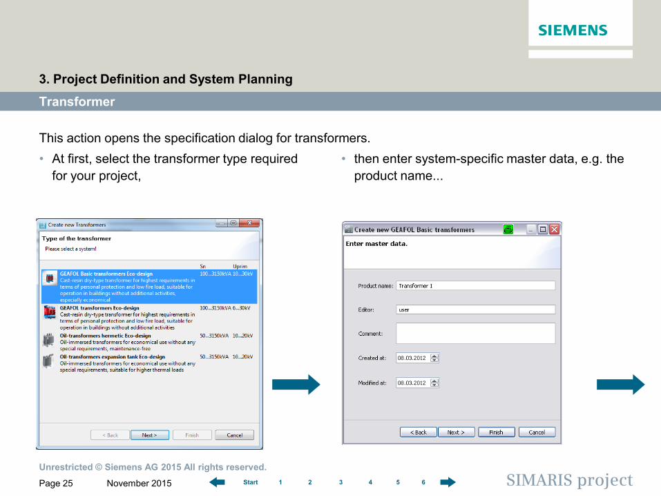
This action opens the specification dialog for transformers.
Transformer
3. Project Definition and System Planning
• At first, select the transformer type required for your project,
• then enter system-specific master data, e.g. the product name...
Unrestricted © Siemens AG 2015 All rights reserved.
November 2015 Page 26 SIMARIS project 1 2 3 4 5 6 Start
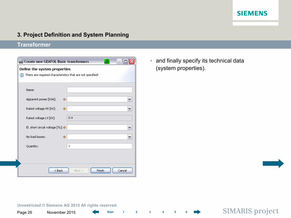
• and finally specify its technical data (system properties).
Transformer
3. Project Definition and System Planning
Unrestricted © Siemens AG 2015 All rights reserved.
November 2015 Page 27 SIMARIS project 1 2 3 4 5 6 Start
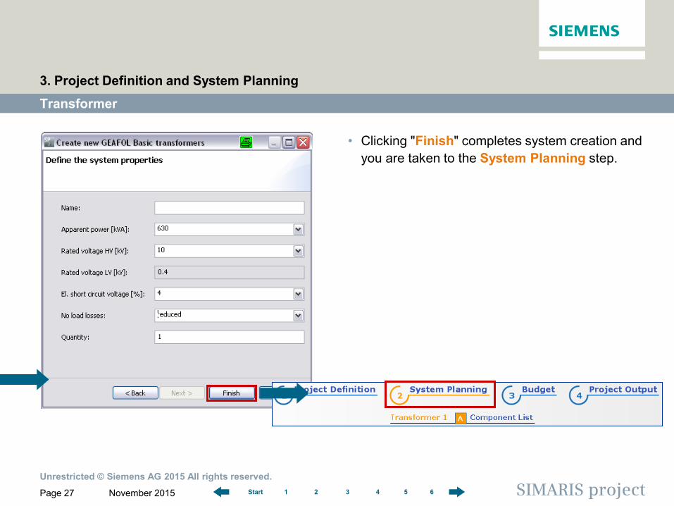
• Clicking "Finish" completes system creation and you are taken to the System Planning step.
Transformer
3. Project Definition and System Planning
Unrestricted © Siemens AG 2015 All rights reserved.
November 2015 Page 28 SIMARIS project 1 2 3 4 5 6 Start
Transformer
3. Project Definition and System Planning
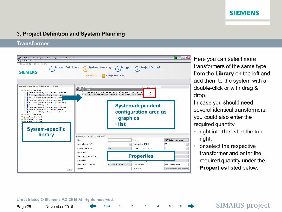
System-specific library
System-dependent configuration area as • graphics • list
Here you can select more transformers of the same type from the Library on the left and add them to the system with a double-click or with drag & drop. In case you should need several identical transformers, you could also enter the required quantity • right into the list at the top
right, • or select the respective
transformer and enter the required quantity under the Properties listed below.
Properties
Unrestricted © Siemens AG 2015 All rights reserved.
November 2015 Page 29 SIMARIS project 1 2 3 4 5 6 Start
Transformer
3. Project Definition and System Planning
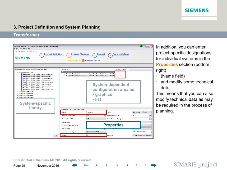
System-specific library
System-dependent configuration area as • graphics • list
In addition, you can enter project-specific designations for individual systems in the Properties section (bottom right) • (Name field) • and modify some technical
data. This means that you can also modify technical data as may be required in the process of planning.
Properties
Unrestricted © Siemens AG 2015 All rights reserved.
November 2015 Page 30 SIMARIS project 1 2 3 4 5 6 Start
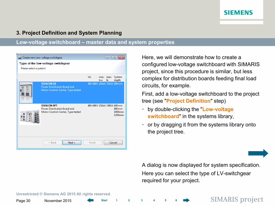
Here, we will demonstrate how to create a configured low-voltage switchboard with SIMARIS project, since this procedure is similar, but less complex for distribution boards feeding final load circuits, for example. First, add a low-voltage switchboard to the project tree (see "Project Definition" step) • by double-clicking the "Low-voltage
switchboard" in the systems library, • or by dragging it from the systems library onto
the project tree. A dialog is now displayed for system specification. Here you can select the type of LV-switchgear required for your project.
Low-voltage switchboard – master data and system properties
3. Project Definition and System Planning
Unrestricted © Siemens AG 2015 All rights reserved.
November 2015 Page 31 SIMARIS project 1 2 3 4 5 6 Start
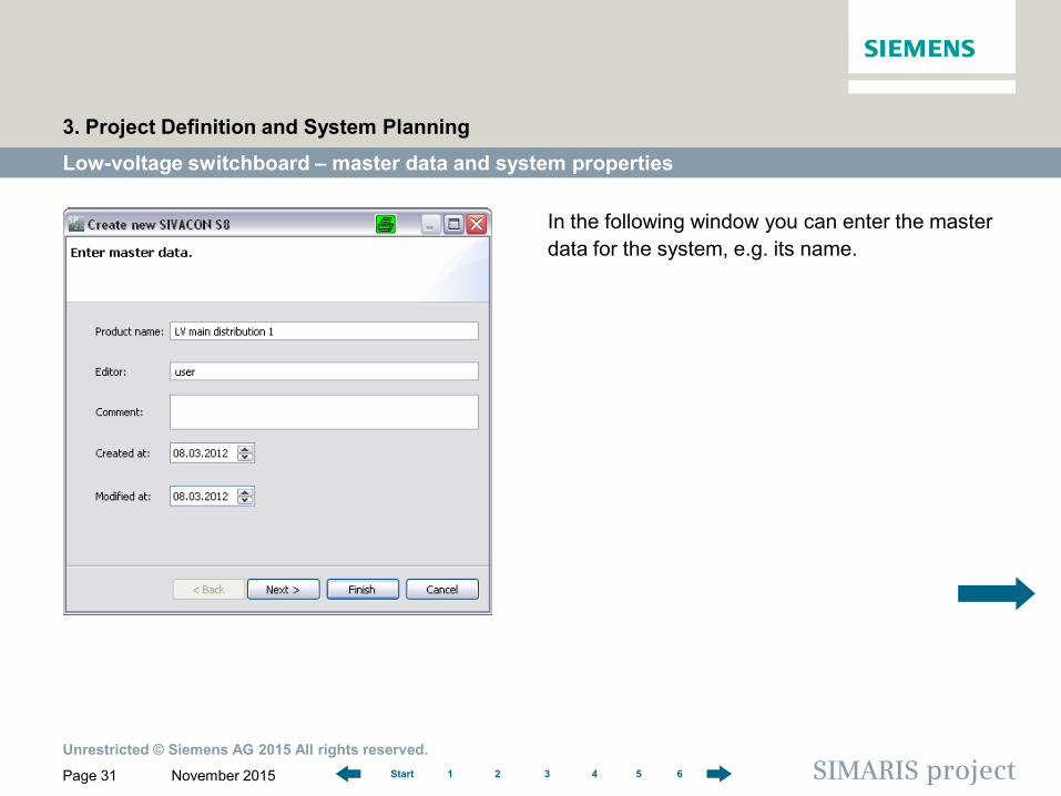
In the following window you can enter the master data for the system, e.g. its name.
Low-voltage switchboard – master data and system properties
3. Project Definition and System Planning
Unrestricted © Siemens AG 2015 All rights reserved.
November 2015 Page 32 SIMARIS project 1 2 3 4 5 6 Start
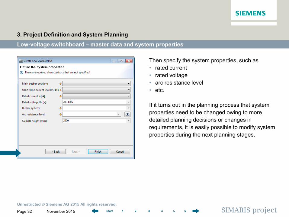
Then specify the system properties, such as • rated current • rated voltage • arc resistance level • etc.
If it turns out in the planning process that system properties need to be changed owing to more detailed planning decisions or changes in requirements, it is easily possible to modify system properties during the next planning stages.
Low-voltage switchboard – master data and system properties
3. Project Definition and System Planning
Unrestricted © Siemens AG 2015 All rights reserved.
November 2015 Page 33 SIMARIS project 1 2 3 4 5 6 Start
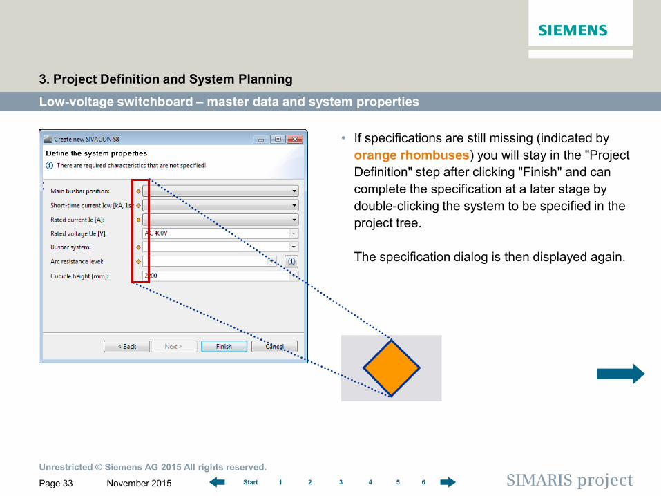
• If specifications are still missing (indicated by orange rhombuses) you will stay in the "Project Definition" step after clicking "Finish" and can complete the specification at a later stage by double-clicking the system to be specified in the project tree. The specification dialog is then displayed again.
Low-voltage switchboard – master data and system properties
3. Project Definition and System Planning
Unrestricted © Siemens AG 2015 All rights reserved.
November 2015 Page 34 SIMARIS project 1 2 3 4 5 6 Start
Low-voltage switchboard – master data and system properties
3. Project Definition and System Planning
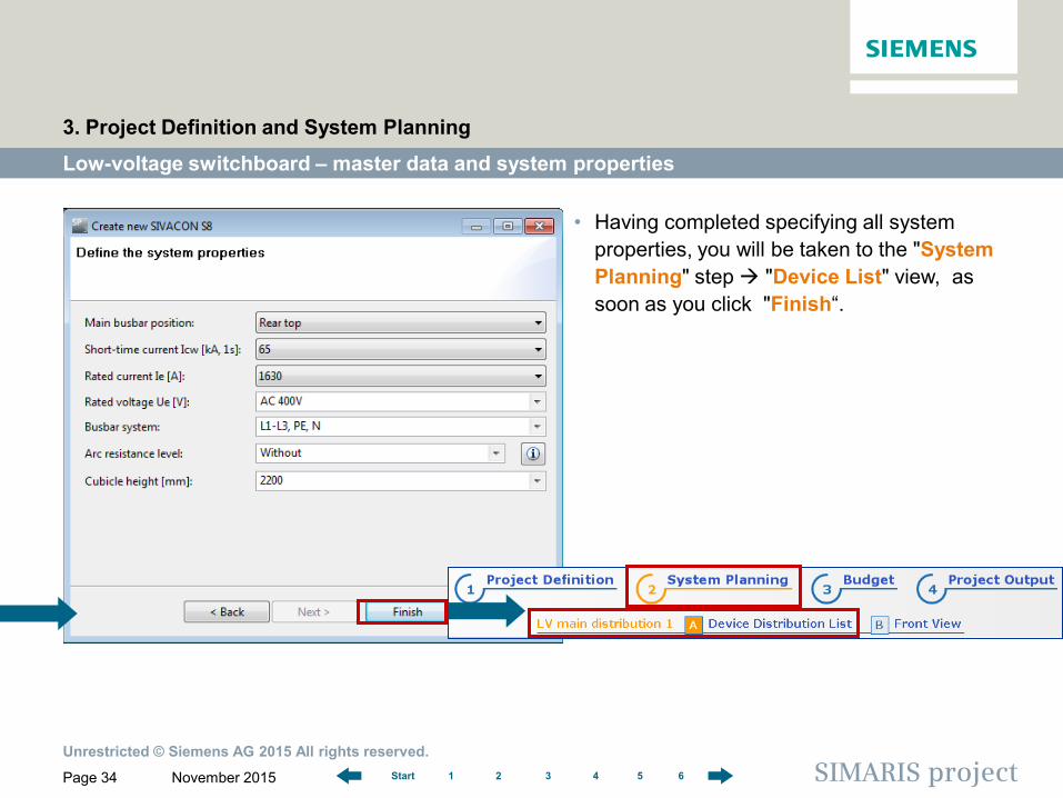
• Having completed specifying all system properties, you will be taken to the "System Planning" step "Device List" view, as soon as you click "Finish“.
Unrestricted © Siemens AG 2015 All rights reserved.
November 2015 Page 35 SIMARIS project 1 2 3 4 5 6 Start
Low-voltage switchboard – device list (for distribution board)
3. Project Definition and System Planning
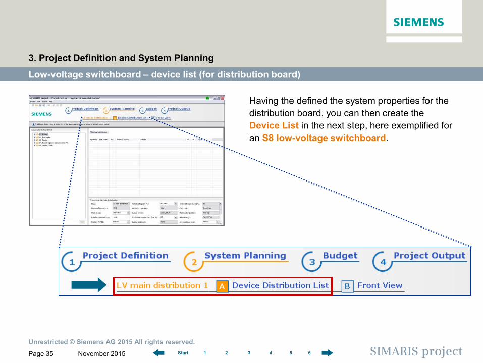
Having the defined the system properties for the distribution board, you can then create the Device List in the next step, here exemplified for an S8 low-voltage switchboard.
Unrestricted © Siemens AG 2015 All rights reserved.
November 2015 Page 36 SIMARIS project 1 2 3 4 5 6 Start
Low-voltage switchboard – device list (for distribution board)
3. Project Definition and System Planning
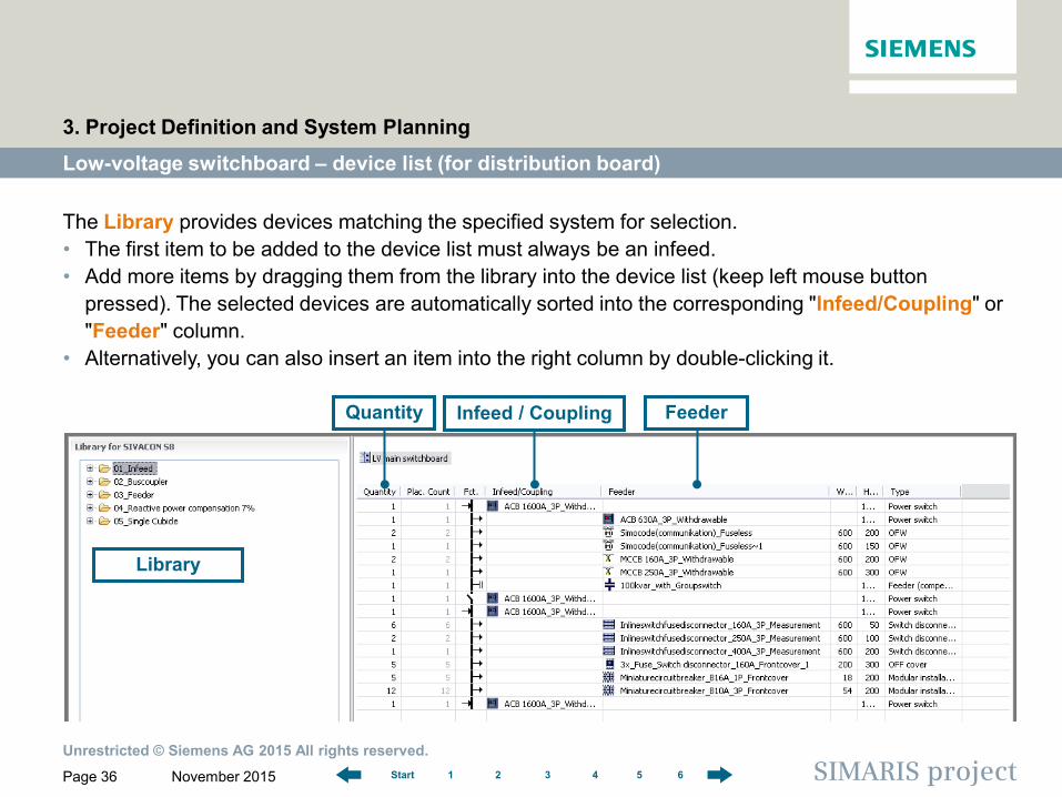
The Library provides devices matching the specified system for selection. • The first item to be added to the device list must always be an infeed. • Add more items by dragging them from the library into the device list (keep left mouse button
pressed). The selected devices are automatically sorted into the corresponding "Infeed/Coupling" or "Feeder" column.
• Alternatively, you can also insert an item into the right column by double-clicking it.
Library
Feeder Infeed / Coupling Quantity
Unrestricted © Siemens AG 2015 All rights reserved.
November 2015 Page 37 SIMARIS project 1 2 3 4 5 6 Start
Low-voltage switchboard – device list (for distribution board)
3. Project Definition and System Planning
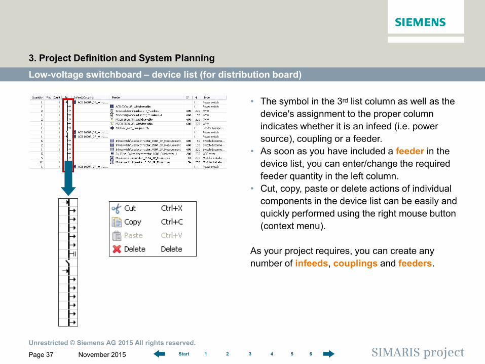
• The symbol in the 3rd list column as well as the device's assignment to the proper column indicates whether it is an infeed (i.e. power source), coupling or a feeder.
• As soon as you have included a feeder in the device list, you can enter/change the required feeder quantity in the left column.
• Cut, copy, paste or delete actions of individual components in the device list can be easily and quickly performed using the right mouse button (context menu).
As your project requires, you can create any number of infeeds, couplings and feeders.
Unrestricted © Siemens AG 2015 All rights reserved.
November 2015 Page 38 SIMARIS project 1 2 3 4 5 6 Start
Low-voltage switchboard – device list (for distribution board)
3. Project Definition and System Planning
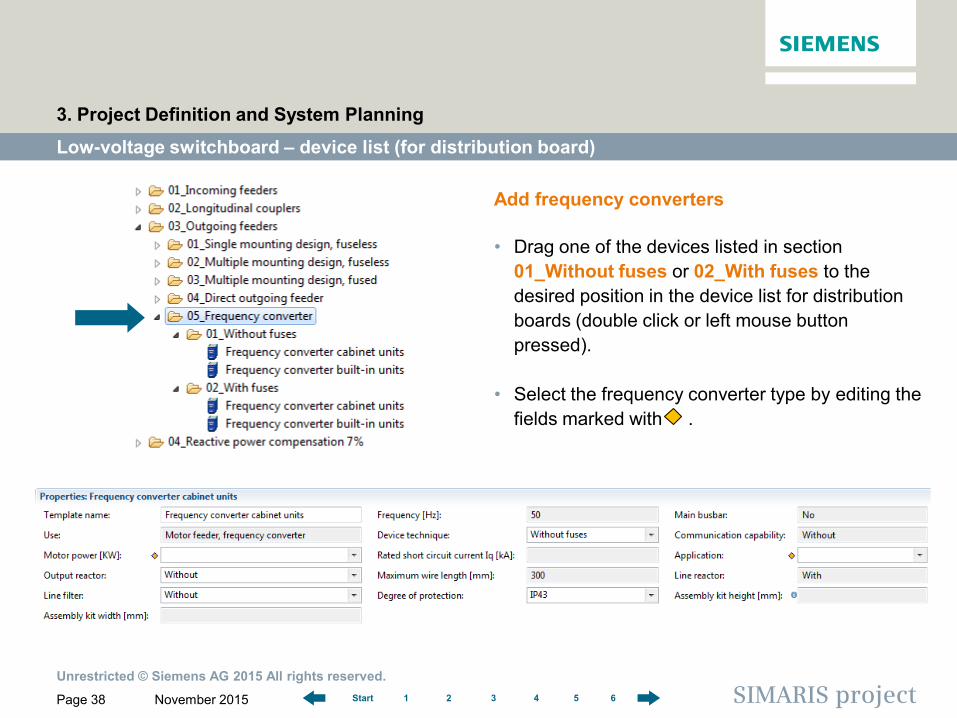
Add frequency converters
• Drag one of the devices listed in section 01_Without fuses or 02_With fuses to the desired position in the device list for distribution boards (double click or left mouse button pressed).
• Select the frequency converter type by editing the fields marked with .
Unrestricted © Siemens AG 2015 All rights reserved.
November 2015 Page 39 SIMARIS project 1 2 3 4 5 6 Start
Low-voltage switchboard – front view
3. Project Definition and System Planning
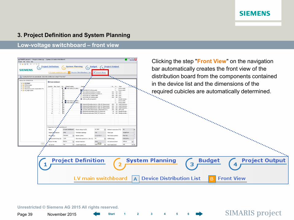
Clicking the step "Front View" on the navigation bar automatically creates the front view of the distribution board from the components contained in the device list and the dimensions of the required cubicles are automatically determined.
Unrestricted © Siemens AG 2015 All rights reserved.
November 2015 Page 40 SIMARIS project 1 2 3 4 5 6 Start
Low-voltage switchboard – front view
3. Project Definition and System Planning
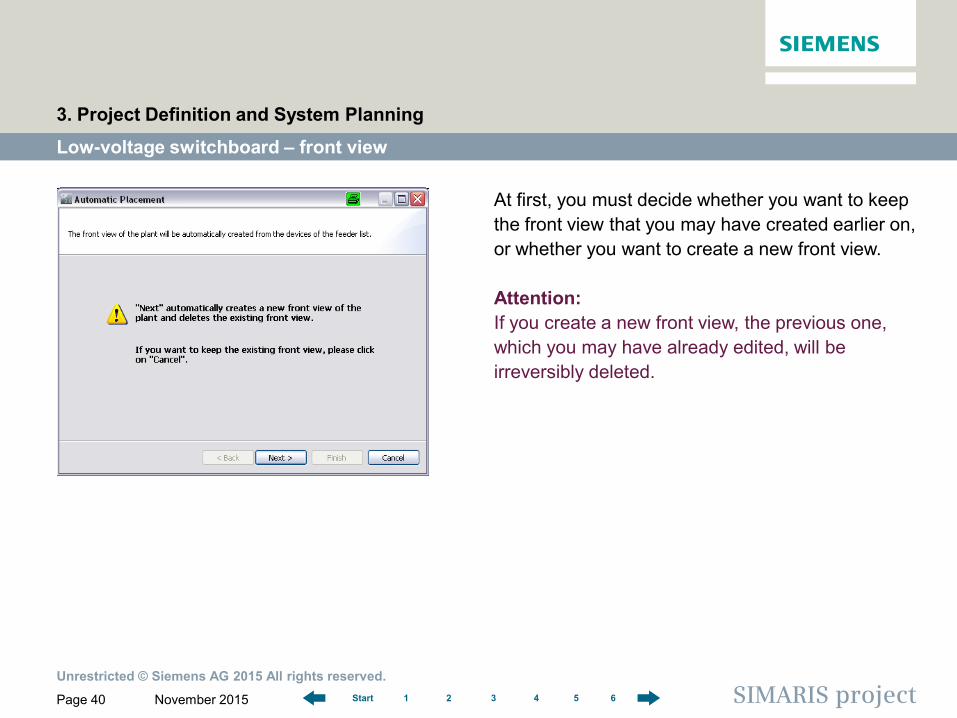
At first, you must decide whether you want to keep the front view that you may have created earlier on, or whether you want to create a new front view. Attention: If you create a new front view, the previous one, which you may have already edited, will be irreversibly deleted.
Unrestricted © Siemens AG 2015 All rights reserved.
November 2015 Page 41 SIMARIS project 1 2 3 4 5 6 Start
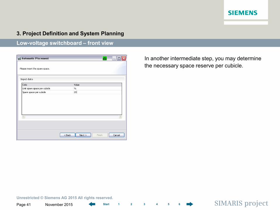
In another intermediate step, you may determine the necessary space reserve per cubicle.
Low-voltage switchboard – front view
3. Project Definition and System Planning
Unrestricted © Siemens AG 2015 All rights reserved.
November 2015 Page 42 SIMARIS project 1 2 3 4 5 6 Start
Low-voltage switchboard – front view
3. Project Definition and System Planning
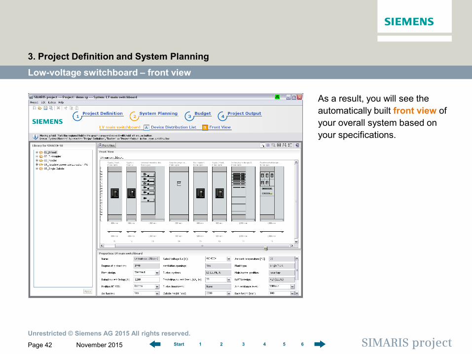
As a result, you will see the automatically built front view of your overall system based on your specifications.
Unrestricted © Siemens AG 2015 All rights reserved.
November 2015 Page 43 SIMARIS project 1 2 3 4 5 6 Start
Low-voltage switchboard – front view
3. Project Definition and System Planning
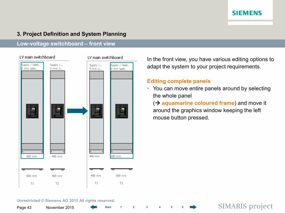
In the front view, you have various editing options to adapt the system to your project requirements. Editing complete panels • You can move entire panels around by selecting
the whole panel ( aquamarine coloured frame) and move it around the graphics window keeping the left mouse button pressed.
Unrestricted © Siemens AG 2015 All rights reserved.
November 2015 Page 44 SIMARIS project 1 2 3 4 5 6 Start
Low-voltage switchboard – front view
3. Project Definition and System Planning
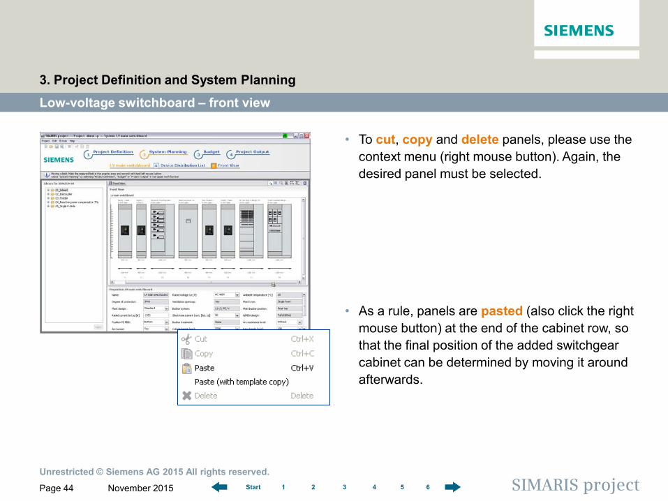
• To cut, copy and delete panels, please use the context menu (right mouse button). Again, the desired panel must be selected.
• As a rule, panels are pasted (also click the right mouse button) at the end of the cabinet row, so that the final position of the added switchgear cabinet can be determined by moving it around afterwards.
Unrestricted © Siemens AG 2015 All rights reserved.
November 2015 Page 45 SIMARIS project 1 2 3 4 5 6 Start
Low-voltage switchboard – front view
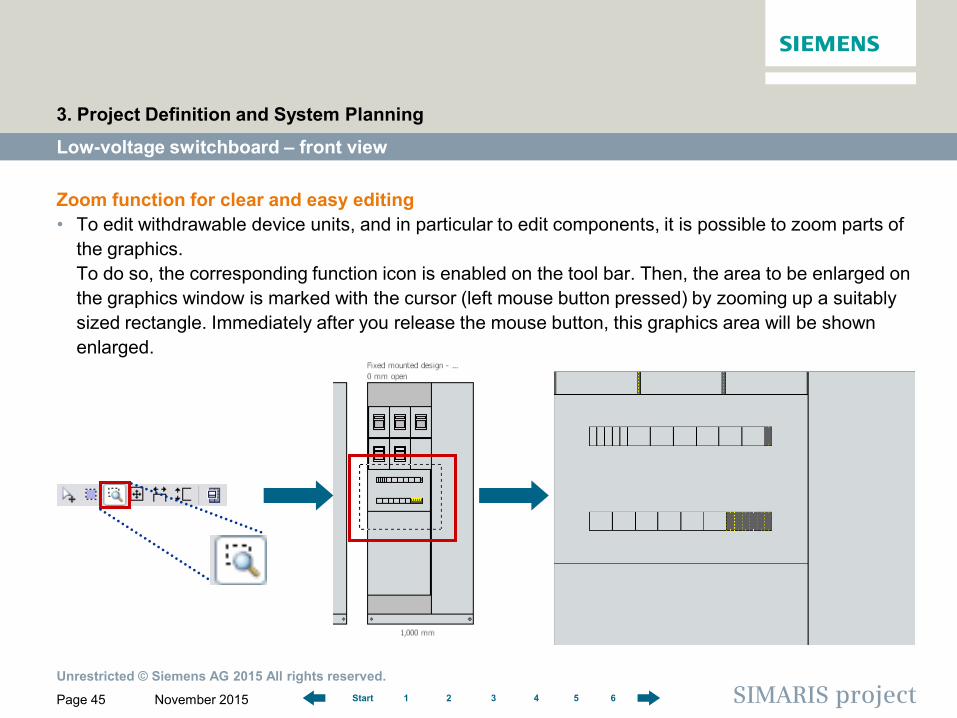
Zoom function for clear and easy editing • To edit withdrawable device units, and in particular to edit components, it is possible to zoom parts of
the graphics. To do so, the corresponding function icon is enabled on the tool bar. Then, the area to be enlarged on the graphics window is marked with the cursor (left mouse button pressed) by zooming up a suitably sized rectangle. Immediately after you release the mouse button, this graphics area will be shown enlarged.
3. Project Definition and System Planning
Unrestricted © Siemens AG 2015 All rights reserved.
November 2015 Page 46 SIMARIS project 1 2 3 4 5 6 Start
Low-voltage switchboard – front view
3. Project Definition and System Planning
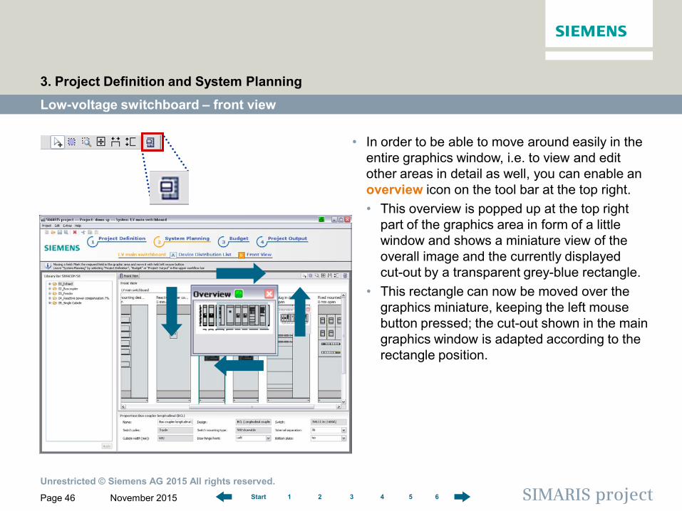
• In order to be able to move around easily in the entire graphics window, i.e. to view and edit other areas in detail as well, you can enable an overview icon on the tool bar at the top right. • This overview is popped up at the top right
part of the graphics area in form of a little window and shows a miniature view of the overall image and the currently displayed cut-out by a transparent grey-blue rectangle.
• This rectangle can now be moved over the graphics miniature, keeping the left mouse button pressed; the cut-out shown in the main graphics window is adapted according to the rectangle position.
Unrestricted © Siemens AG 2015 All rights reserved.
November 2015 Page 47 SIMARIS project 1 2 3 4 5 6 Start
Low-voltage switchboard – front view
3. Project Definition and System Planning
Editing withdrawable device units and components Similar to the procedure of editing cubicles, entire withdrawable device units or components can be moved around in the graphics window, or copied, cut out, pasted, or deleted to match panel building to project requirements. But this is only possible if additional space is left in the distribution board • to accommodate withdrawable units or fixed-mounted devices elsewhere. • This applies to the space inside the withdrawable unit required for placing devices,
too.
Unrestricted © Siemens AG 2015 All rights reserved.
November 2015 Page 48 SIMARIS project 1 2 3 4 5 6 Start
Low-voltage switchboard – front view
3. Project Definition and System Planning
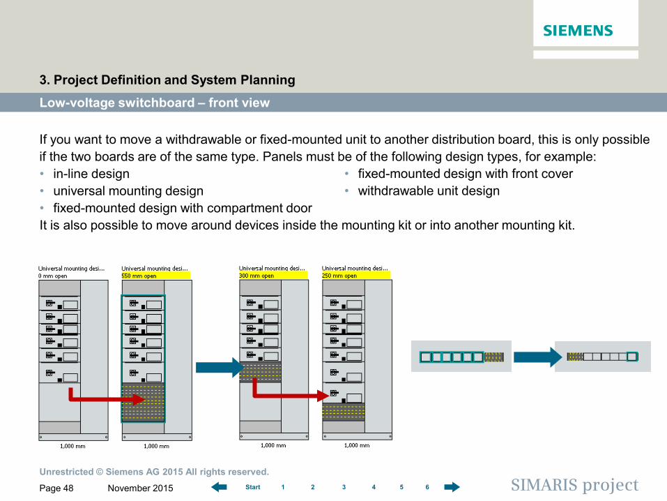
If you want to move a withdrawable or fixed-mounted unit to another distribution board, this is only possible if the two boards are of the same type. Panels must be of the following design types, for example: • in-line design • universal mounting design • fixed-mounted design with compartment door It is also possible to move around devices inside the mounting kit or into another mounting kit.
• fixed-mounted design with front cover • withdrawable unit design
Unrestricted © Siemens AG 2015 All rights reserved.
November 2015 Page 49 SIMARIS project 1 2 3 4 5 6 Start
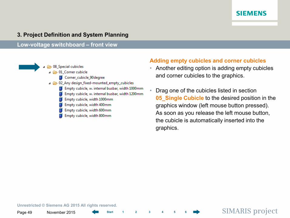
Adding empty cubicles and corner cubicles • Another editing option is adding empty cubicles
and corner cubicles to the graphics.
• Drag one of the cubicles listed in section 05_Single Cubicle to the desired position in the graphics window (left mouse button pressed). As soon as you release the left mouse button, the cubicle is automatically inserted into the graphics.
Low-voltage switchboard – front view
3. Project Definition and System Planning
Unrestricted © Siemens AG 2015 All rights reserved.
November 2015 Page 50 SIMARIS project 1 2 3 4 5 6 Start
Low-voltage switchboard – front view
3. Project Definition and System Planning
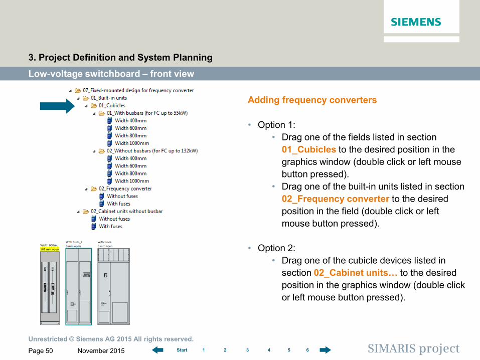
Adding frequency converters • Option 1:
• Drag one of the fields listed in section 01_Cubicles to the desired position in the graphics window (double click or left mouse button pressed).
• Drag one of the built-in units listed in section 02_Frequency converter to the desired position in the field (double click or left mouse button pressed).
• Option 2: • Drag one of the cubicle devices listed in
section 02_Cabinet units… to the desired position in the graphics window (double click or left mouse button pressed).
Unrestricted © Siemens AG 2015 All rights reserved.
November 2015 Page 51 SIMARIS project 1 2 3 4 5 6 Start
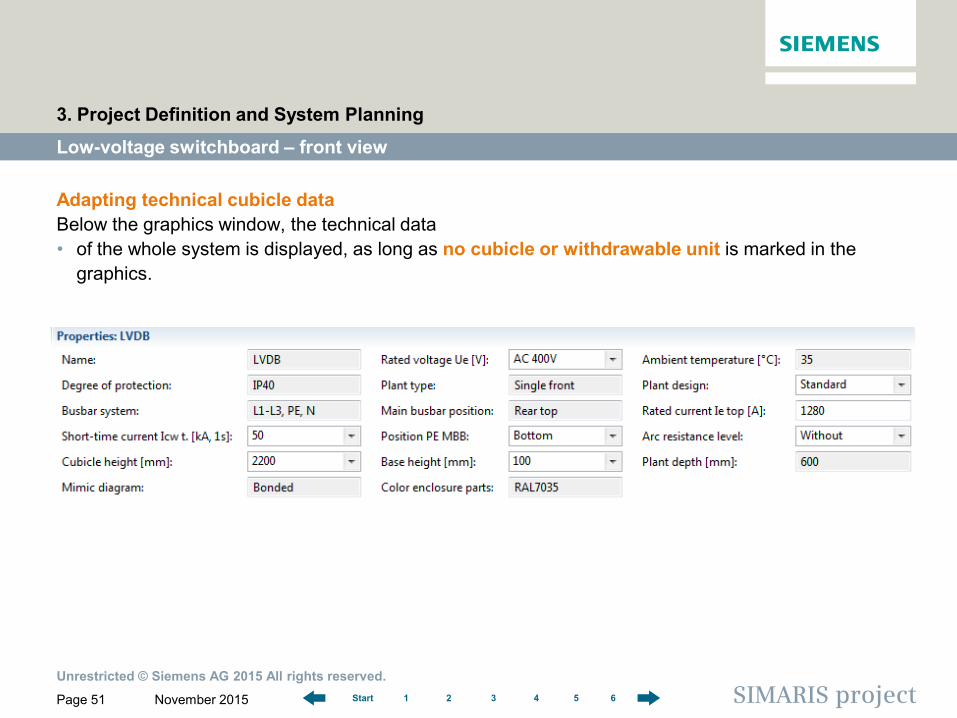
Adapting technical cubicle data Below the graphics window, the technical data • of the whole system is displayed, as long as no cubicle or withdrawable unit is marked in the
graphics.
Low-voltage switchboard – front view
3. Project Definition and System Planning
Unrestricted © Siemens AG 2015 All rights reserved.
November 2015 Page 52 SIMARIS project 1 2 3 4 5 6 Start
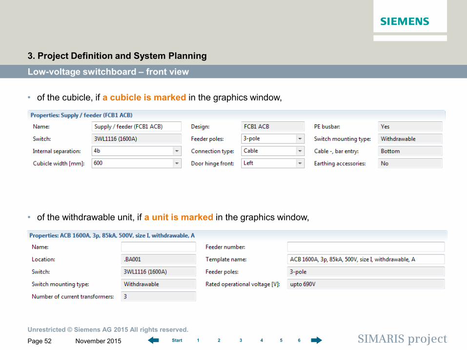
• of the cubicle, if a cubicle is marked in the graphics window,
• of the withdrawable unit, if a unit is marked in the graphics window,
Low-voltage switchboard – front view
3. Project Definition and System Planning
Unrestricted © Siemens AG 2015 All rights reserved.
November 2015 Page 53 SIMARIS project 1 2 3 4 5 6 Start
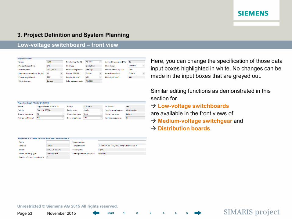
Here, you can change the specification of those data input boxes highlighted in white. No changes can be made in the input boxes that are greyed out. Similar editing functions as demonstrated in this section for Low-voltage switchboards are available in the front views of Medium-voltage switchgear and Distribution boards.
Low-voltage switchboard – front view
3. Project Definition and System Planning
Unrestricted © Siemens AG 2015 All rights reserved.
November 2015 Page 54 SIMARIS project 1 2 3 4 5 6 Start
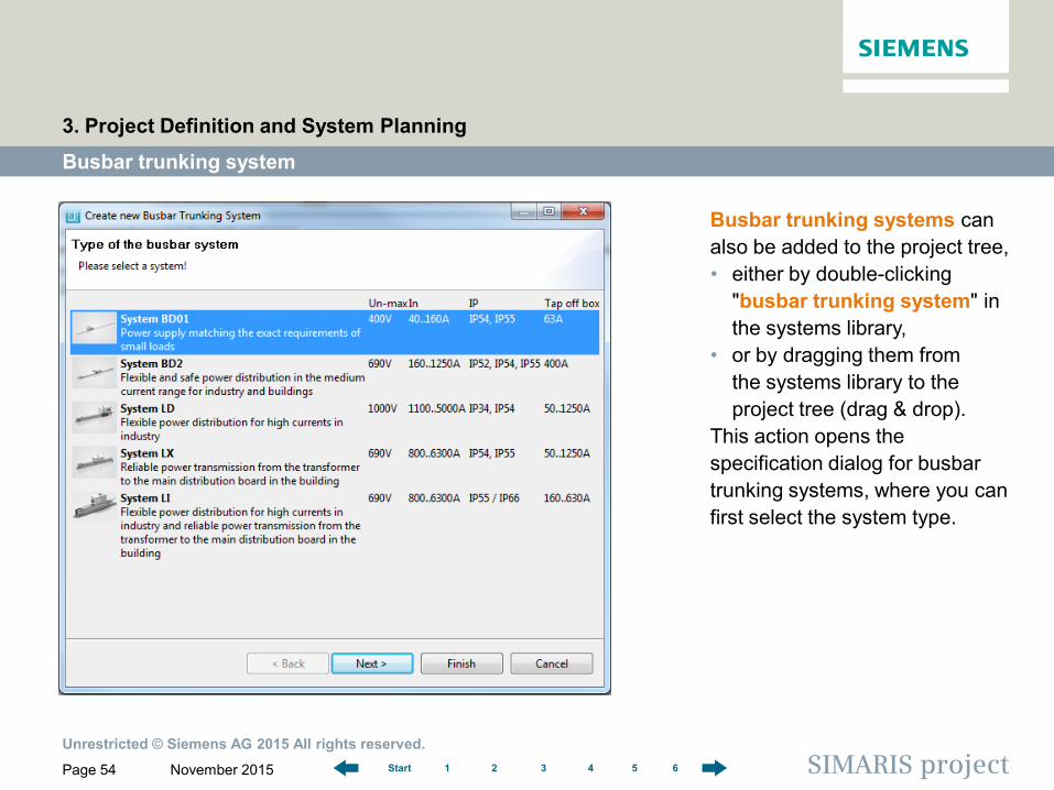
Busbar trunking systems can also be added to the project tree, • either by double-clicking
"busbar trunking system" in the systems library,
• or by dragging them from the systems library to the project tree (drag & drop).
This action opens the specification dialog for busbar trunking systems, where you can first select the system type.
Busbar trunking system
3. Project Definition and System Planning
Unrestricted © Siemens AG 2015 All rights reserved.
November 2015 Page 55 SIMARIS project 1 2 3 4 5 6 Start
Busbar trunking system
3. Project Definition and System Planning
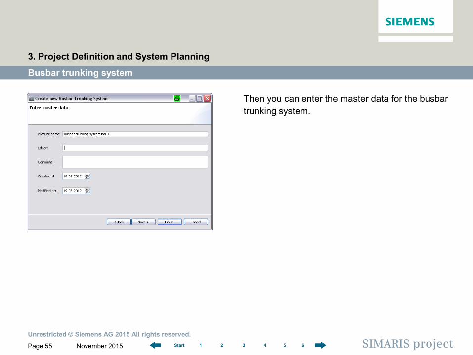
Then you can enter the master data for the busbar trunking system.
Unrestricted © Siemens AG 2015 All rights reserved.
November 2015 Page 56 SIMARIS project 1 2 3 4 5 6 Start
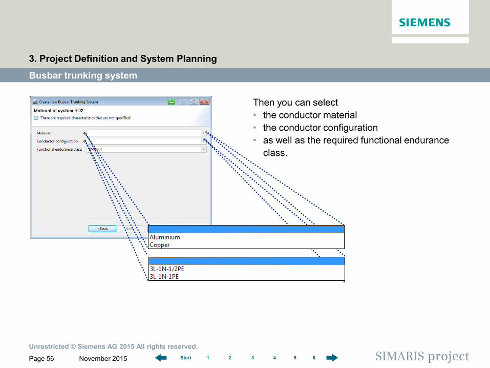
Then you can select • the conductor material • the conductor configuration • as well as the required functional endurance
class.
Busbar trunking system
3. Project Definition and System Planning
Unrestricted © Siemens AG 2015 All rights reserved.
November 2015 Page 57 SIMARIS project 1 2 3 4 5 6 Start
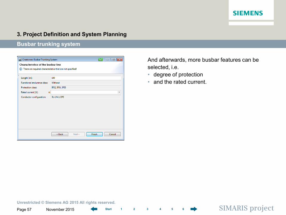
And afterwards, more busbar features can be selected, i.e. • degree of protection • and the rated current.
Busbar trunking system
3. Project Definition and System Planning
Unrestricted © Siemens AG 2015 All rights reserved.
November 2015 Page 58 SIMARIS project 1 2 3 4 5 6 Start
Busbar trunking system
3. Project Definition and System Planning
As long as you haven't completed specifying all missing features, you will stay in the "Project Definition" step. You can open the specification dialog again at any time by double-clicking the system. Only after all of the required data have been specified, you are taken to the "System Planning" step. In the component list for the configured busbar trunking system, which is displayed there, you can then specify the number of • tap-off points • cable feeders • distribution board connection units • 90° directional change components and enter the quantities into the component list, as your project requires.
Unrestricted © Siemens AG 2015 All rights reserved.
November 2015 Page 59 SIMARIS project 1 2 3 4 5 6 Start
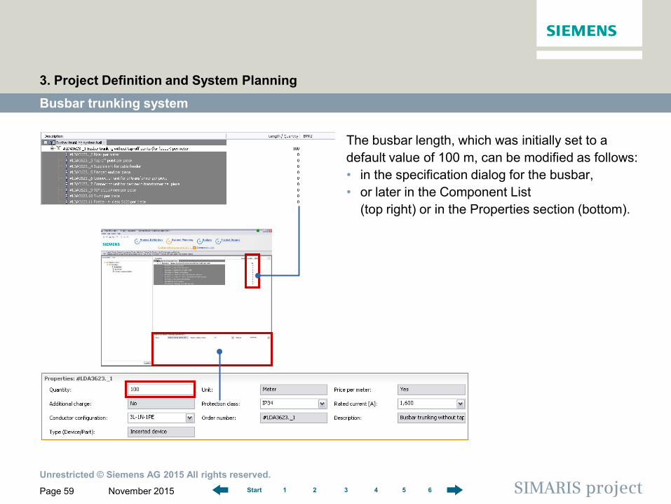
The busbar length, which was initially set to a default value of 100 m, can be modified as follows: • in the specification dialog for the busbar, • or later in the Component List
(top right) or in the Properties section (bottom).
Busbar trunking system
3. Project Definition and System Planning
Unrestricted © Siemens AG 2015 All rights reserved.
November 2015 Page 60 SIMARIS project 1 2 3 4 5 6 Start
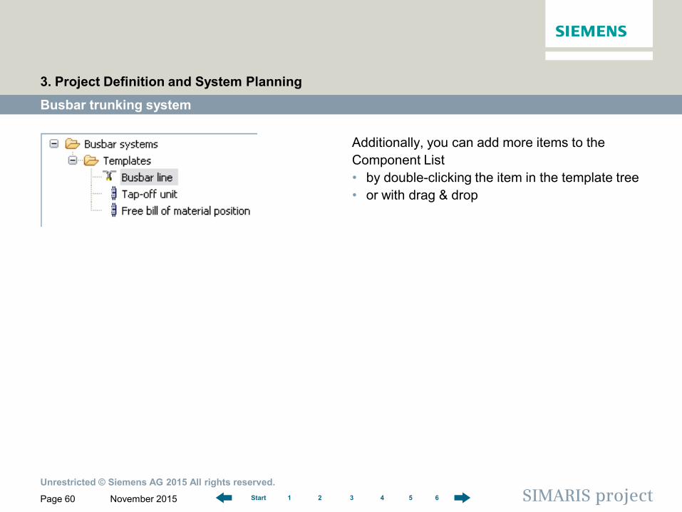
Additionally, you can add more items to the Component List • by double-clicking the item in the template tree • or with drag & drop
Busbar trunking system
3. Project Definition and System Planning
Unrestricted © Siemens AG 2015 All rights reserved.
November 2015 Page 61 SIMARIS project 1 2 3 4 5 6 Start
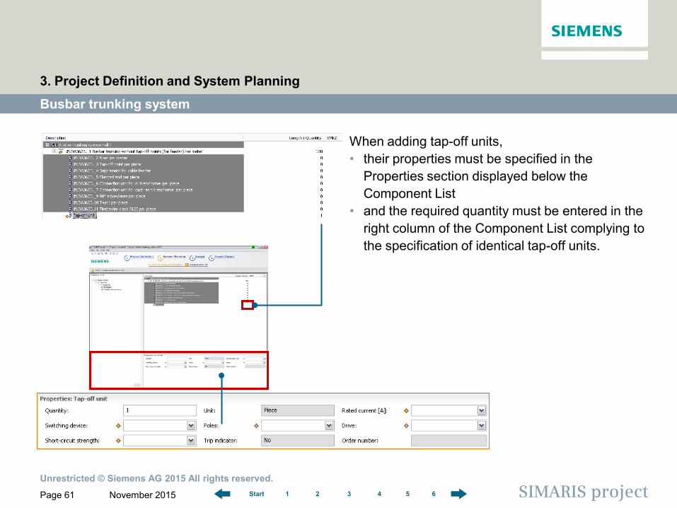
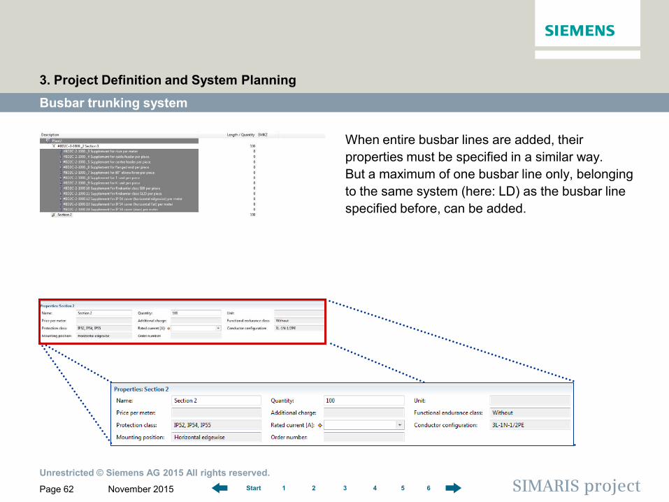
When adding tap-off units, • their properties must be specified in the
Properties section displayed below the Component List
• and the required quantity must be entered in the right column of the Component List complying to the specification of identical tap-off units.
Busbar trunking system
3. Project Definition and System Planning
Unrestricted © Siemens AG 2015 All rights reserved.
November 2015 Page 62 SIMARIS project 1 2 3 4 5 6 Start
When entire busbar lines are added, their properties must be specified in a similar way. But a maximum of one busbar line only, belonging to the same system (here: LD) as the busbar line specified before, can be added.
Busbar trunking system
3. Project Definition and System Planning
Unrestricted © Siemens AG 2015 All rights reserved.
November 2015 Page 63 SIMARIS project 1 2 3 4 5 6 Start
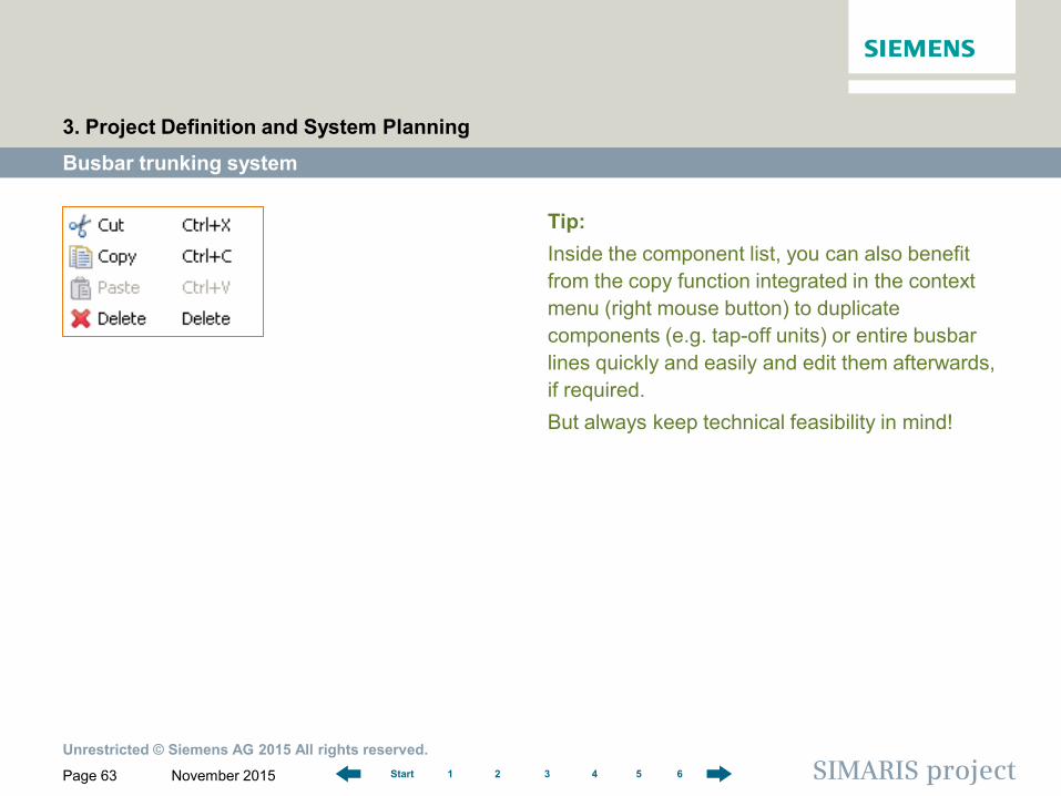
Tip: Inside the component list, you can also benefit from the copy function integrated in the context menu (right mouse button) to duplicate components (e.g. tap-off units) or entire busbar lines quickly and easily and edit them afterwards, if required. But always keep technical feasibility in mind!
Busbar trunking system
3. Project Definition and System Planning
Unrestricted © Siemens AG 2015 All rights reserved.
November 2015 Page 64 SIMARIS project 1 2 3 4 5 6 Start
Tips and tricks for system planning
3. Project Definition and System Planning
In the following, you will find some tips and tricks that ease the work with SIMARIS project and make it even more efficient, such as • copying entire systems/plants • saving typicals as Favourites to reuse them in a new project • importing a complete network designed in SIMARIS design 9 professional to
configure the switchgear cabinets and other components in SIMARIS project which are required for project implementation.
Unrestricted © Siemens AG 2015 All rights reserved.
November 2015 Page 65 SIMARIS project 1 2 3 4 5 6 Start
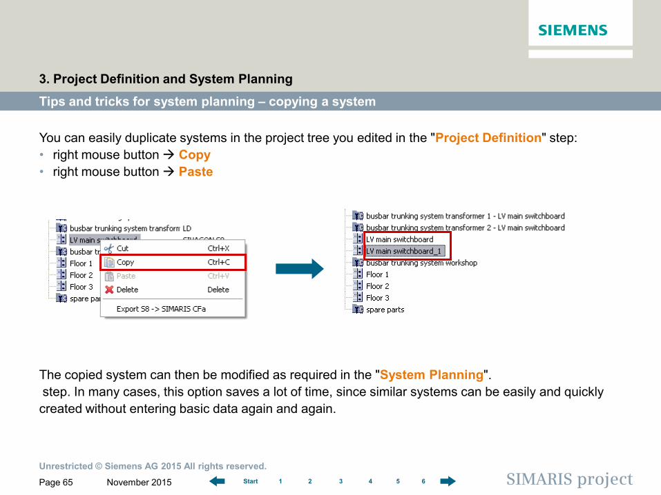
You can easily duplicate systems in the project tree you edited in the "Project Definition" step: • right mouse button Copy • right mouse button Paste
Tips and tricks for system planning – copying a system
3. Project Definition and System Planning
The copied system can then be modified as required in the "System Planning". step. In many cases, this option saves a lot of time, since similar systems can be easily and quickly created without entering basic data again and again.
Unrestricted © Siemens AG 2015 All rights reserved.
November 2015 Page 66 SIMARIS project 1 2 3 4 5 6 Start
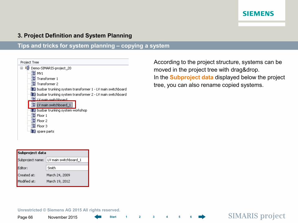
According to the project structure, systems can be moved in the project tree with drag&drop. In the Subproject data displayed below the project tree, you can also rename copied systems.
Tips and tricks for system planning – copying a system
3. Project Definition and System Planning
Unrestricted © Siemens AG 2015 All rights reserved.
November 2015 Page 67 SIMARIS project 1 2 3 4 5 6 Start
Tips and tricks for system planning - favourites library
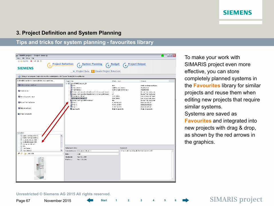
To make your work with SIMARIS project even more effective, you can store completely planned systems in the Favourites library for similar projects and reuse them when editing new projects that require similar systems. Systems are saved as Favourites and integrated into new projects with drag & drop, as shown by the red arrows in the graphics.
3. Project Definition and System Planning
Unrestricted © Siemens AG 2015 All rights reserved.
November 2015 Page 68 SIMARIS project 1 2 3 4 5 6 Start
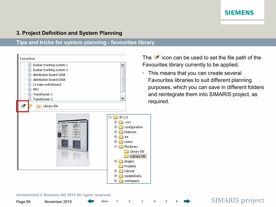
The icon can be used to set the file path of the Favourites library currently to be applied. • This means that you can create several
Favourites libraries to suit different planning purposes, which you can save in different folders and reintegrate them into SIMARIS project, as required.
Tips and tricks for system planning - favourites library
3. Project Definition and System Planning
Unrestricted © Siemens AG 2015 All rights reserved.
November 2015 Page 69 SIMARIS project 1 2 3 4 5 6 Start
Tips and tricks for system planning - favourites library
3. Project Definition and System Planning
• If you want to modify your filing structure, e.g. • move systems from one library to another • or rename Favourites,
you can do this directly in the directory structure of the storage medium (e.g. hard disk). However, you must then update the file path of the currently linked Favourites library in SIMARIS project using the icon.
• This way, you can gradually build up your own Favourites while editing various projects, which you can rely on when you start editing new projects.
• Of course, it is always possible to edit systems copied from the Favourites library in SIMARIS project to adapt these systems to specific project requirements.
Unrestricted © Siemens AG 2015 All rights reserved.
November 2015 Page 70 SIMARIS project 1 2 3 4 5 6 Start
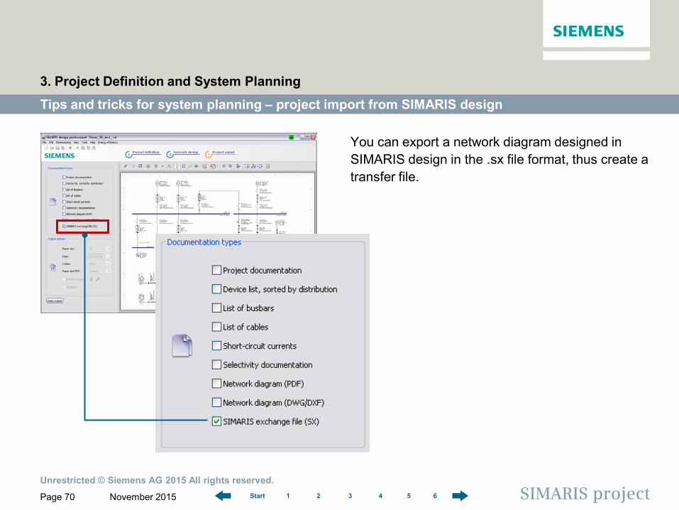
You can export a network diagram designed in SIMARIS design in the .sx file format, thus create a transfer file.
Tips and tricks for system planning – project import from SIMARIS design
3. Project Definition and System Planning
Unrestricted © Siemens AG 2015 All rights reserved.
November 2015 Page 71 SIMARIS project 1 2 3 4 5 6 Start
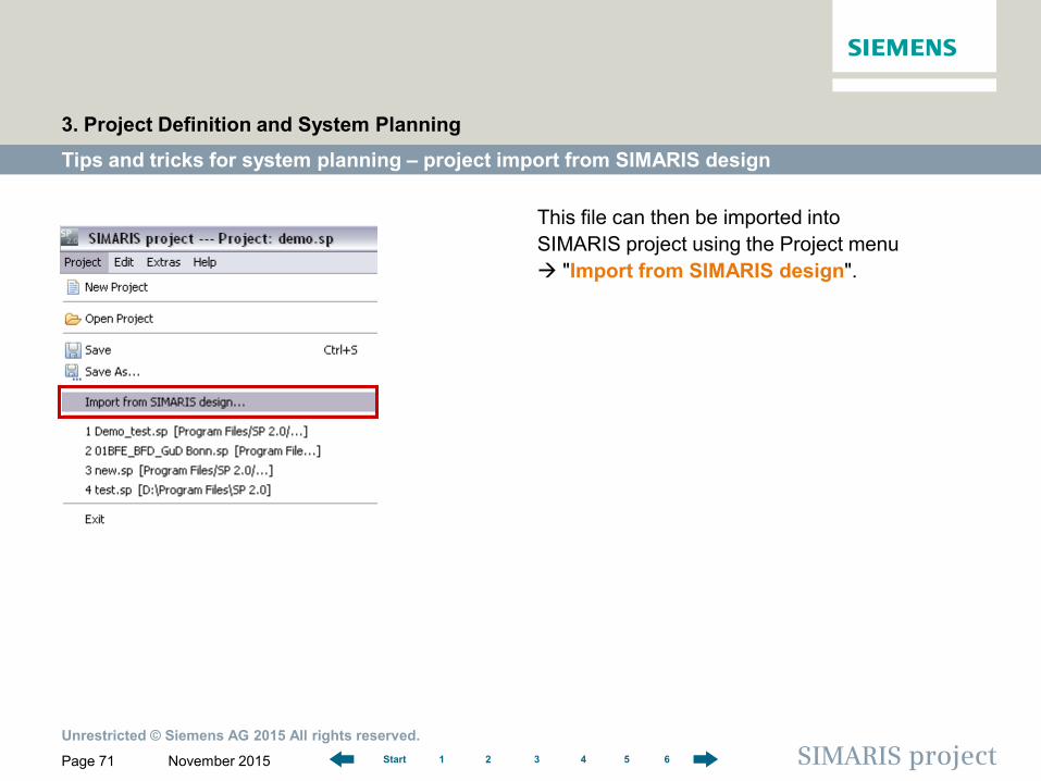
This file can then be imported into SIMARIS project using the Project menu "Import from SIMARIS design".
Tips and tricks for system planning – project import from SIMARIS design
3. Project Definition and System Planning
Unrestricted © Siemens AG 2015 All rights reserved.
November 2015 Page 72 SIMARIS project 1 2 3 4 5 6 Start
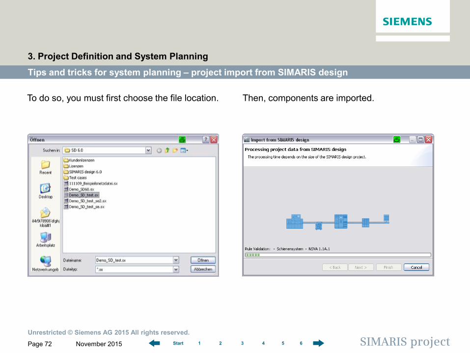
Then, components are imported.
Tips and tricks for system planning – project import from SIMARIS design
3. Project Definition and System Planning
To do so, you must first choose the file location.
Unrestricted © Siemens AG 2015 All rights reserved.
November 2015 Page 73 SIMARIS project 1 2 3 4 5 6 Start
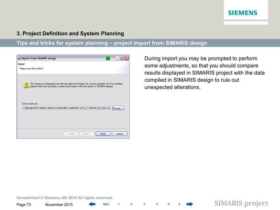
During import you may be prompted to perform some adjustments, so that you should compare results displayed in SIMARIS project with the data compiled in SIMARIS design to rule out unexpected alterations.
Tips and tricks for system planning – project import from SIMARIS design
3. Project Definition and System Planning
Unrestricted © Siemens AG 2015 All rights reserved.
November 2015 Page 74 SIMARIS project 1 2 3 4 5 6 Start
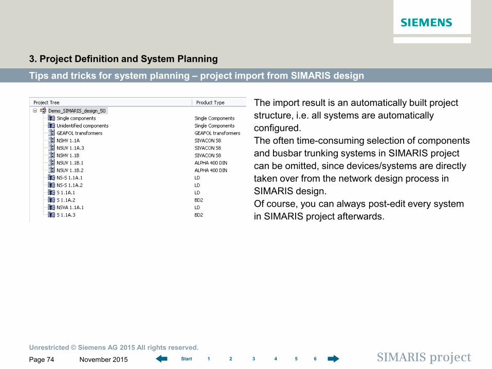
The import result is an automatically built project structure, i.e. all systems are automatically configured. The often time-consuming selection of components and busbar trunking systems in SIMARIS project can be omitted, since devices/systems are directly taken over from the network design process in SIMARIS design. Of course, you can always post-edit every system in SIMARIS project afterwards.
Tips and tricks for system planning – project import from SIMARIS design
3. Project Definition and System Planning
Unrestricted © Siemens AG 2015 All rights reserved.
November 2015 Page 75 SIMARIS project 1 2 3 4 5 6 Start
Tips and tricks for system planning – project import from SIMARIS design
3. Project Definition and System Planning
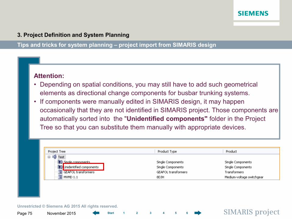
Attention: • Depending on spatial conditions, you may still have to add such geometrical
elements as directional change components for busbar trunking systems. • If components were manually edited in SIMARIS design, it may happen
occasionally that they are not identified in SIMARIS project. Those components are automatically sorted into the "Unidentified components" folder in the Project Tree so that you can substitute them manually with appropriate devices.
Page 76
Software for determining the space requirements and budget for electric power distribution
1 2 3 4 5 6 Start SIMARIS project
SIMARIS project Tutorial
1 Introduction
2 Getting Started
3 Project Definition and System Planning
4 Budget
5 Project Output
6 More about SIMARIS
Budget
4 Budget
> Budget on Demand > Budget Summary
Unrestricted © Siemens AG 2015 All rights reserved.
November 2015 Page 77 SIMARIS project 1 2 3 4 5 6 Start
Budget on demand
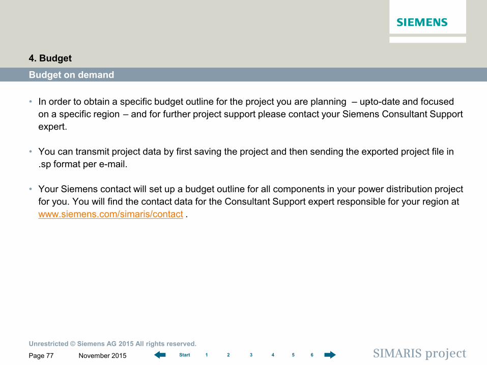
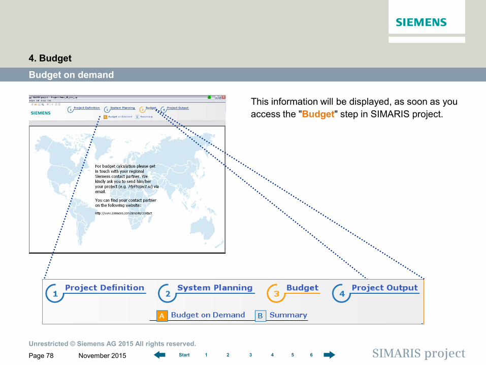
• In order to obtain a specific budget outline for the project you are planning ‒ up-to-date and focused on a specific region ‒ and for further project support please contact your Siemens Consultant Support expert.
• You can transmit project data by first saving the project and then sending the exported project file in .sp format per e-mail.
• Your Siemens contact will set up a budget outline for all components in your power distribution project for you. You will find the contact data for the Consultant Support expert responsible for your region at www.siemens.com/simaris/contact .
4. Budget
Unrestricted © Siemens AG 2015 All rights reserved.
November 2015 Page 78 SIMARIS project 1 2 3 4 5 6 Start
This information will be displayed, as soon as you access the "Budget" step in SIMARIS project.
Budget on demand
4. Budget
Unrestricted © Siemens AG 2015 All rights reserved.
November 2015 Page 79 SIMARIS project 1 2 3 4 5 6 Start
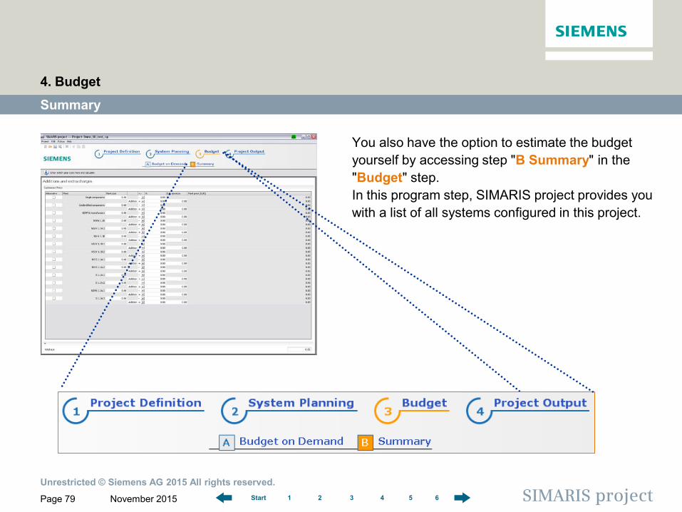
You also have the option to estimate the budget yourself by accessing step "B Summary" in the "Budget" step. In this program step, SIMARIS project provides you with a list of all systems configured in this project.
Summary
4. Budget
Unrestricted © Siemens AG 2015 All rights reserved.
November 2015 Page 80 SIMARIS project 1 2 3 4 5 6 Start
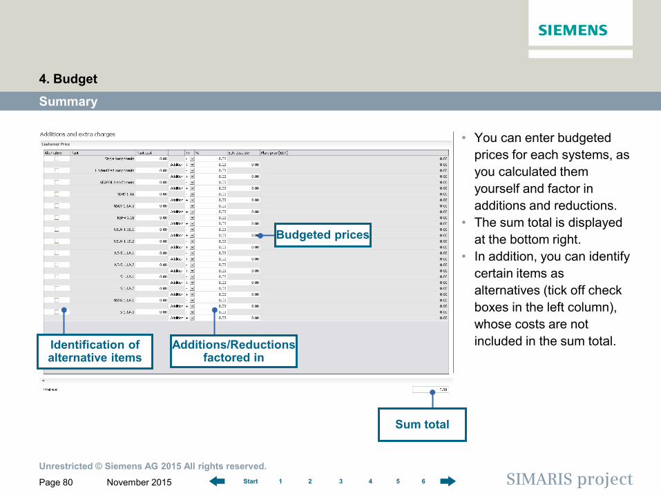
Summary
• You can enter budgeted prices for each systems, as you calculated them yourself and factor in additions and reductions.
• The sum total is displayed at the bottom right.
• In addition, you can identify certain items as alternatives (tick off check boxes in the left column), whose costs are not included in the sum total.
4. Budget
Identification of alternative items
Additions/Reductions factored in
Budgeted prices
Sum total
Page 81
Software for determining the space requirements and budget for electric power distribution
1 2 3 4 5 6 Start SIMARIS project
SIMARIS project Tutorial
1 Introduction
2 Getting Started
3 Project Definition and System Planning
4 Budget
5 Project Output
6 More about SIMARIS
5 Project Output
Overview Project documentation (complete) Views Creation of technical specification

Unrestricted © Siemens AG 2015 All rights reserved.
November 2015 Page 82 SIMARIS project 1 2 3 4 5 6 Start
• In the "Project Output" step, you can easily and quickly create the project documentation.
Overview
5. Project Output
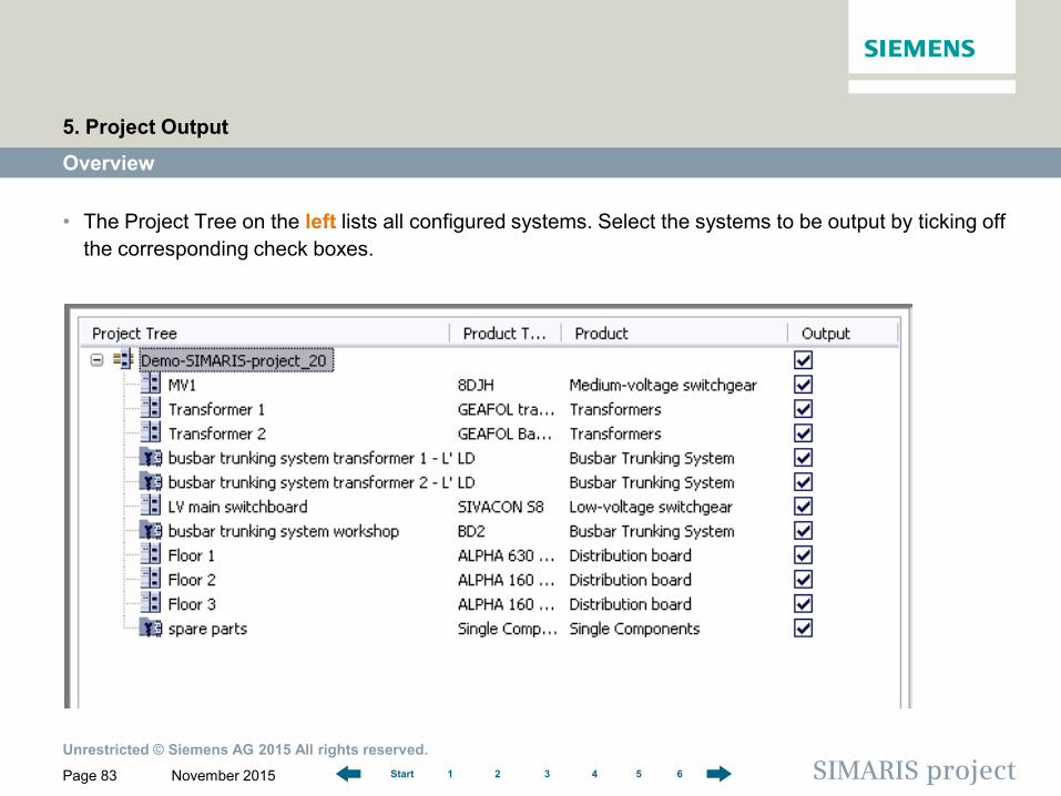
Overview of project output options
Project tree for component/product
selection Selection of the desired
output variants
Unrestricted © Siemens AG 2015 All rights reserved.
November 2015 Page 83 SIMARIS project 1 2 3 4 5 6 Start
Overview
• The Project Tree on the left lists all configured systems. Select the systems to be output by ticking off the corresponding check boxes.
5. Project Output
Unrestricted © Siemens AG 2015 All rights reserved.
November 2015 Page 84 SIMARIS project 1 2 3 4 5 6 Start
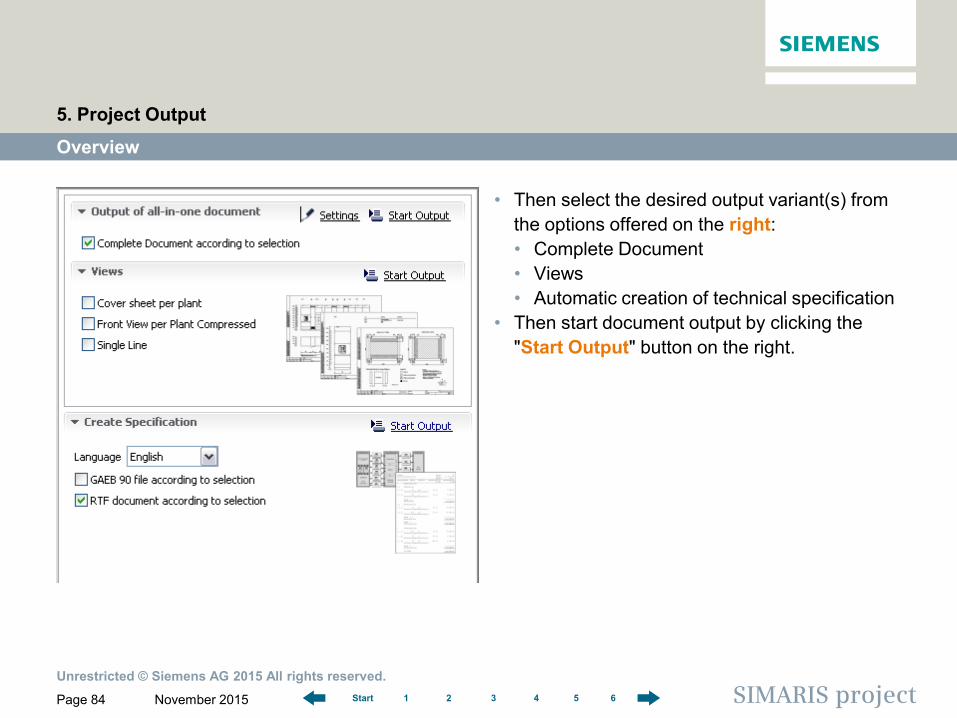
• Then select the desired output variant(s) from the options offered on the right: • Complete Document • Views • Automatic creation of technical specification
• Then start document output by clicking the "Start Output" button on the right.
Overview
5. Project Output
Unrestricted © Siemens AG 2015 All rights reserved.
November 2015 Page 85 SIMARIS project 1 2 3 4 5 6 Start
Overview
5. Project Output
Please note that not all of the output options are available for every system or plant. The output options of "Cover sheet per plant" and "Front view per plant" are only available for • medium-voltage switchgear • transformers • low-voltage switchboards • distribution boards A "Single Line" diagram and "System Drawing" are only available for • medium-voltage switchgear • low-voltage switchboards The output option "System Drawing" is only available within the regionalization for China.
Unrestricted © Siemens AG 2015 All rights reserved.
November 2015 Page 86 SIMARIS project 1 2 3 4 5 6 Start
Project documentation (complete)
5. Project Output
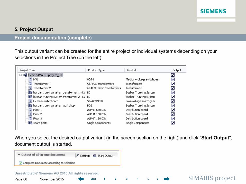
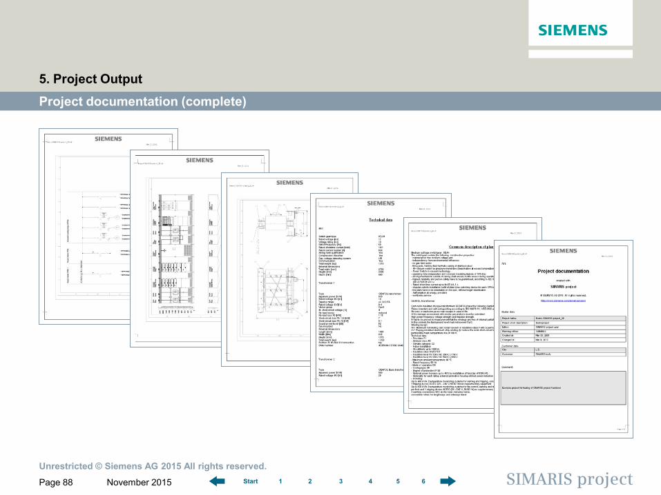
This output variant can be created for the entire project or individual systems depending on your selections in the Project Tree (on the left).
When you select the desired output variant (in the screen section on the right) and click "Start Output", document output is started.
Unrestricted © Siemens AG 2015 All rights reserved.
November 2015 Page 87 SIMARIS project 1 2 3 4 5 6 Start
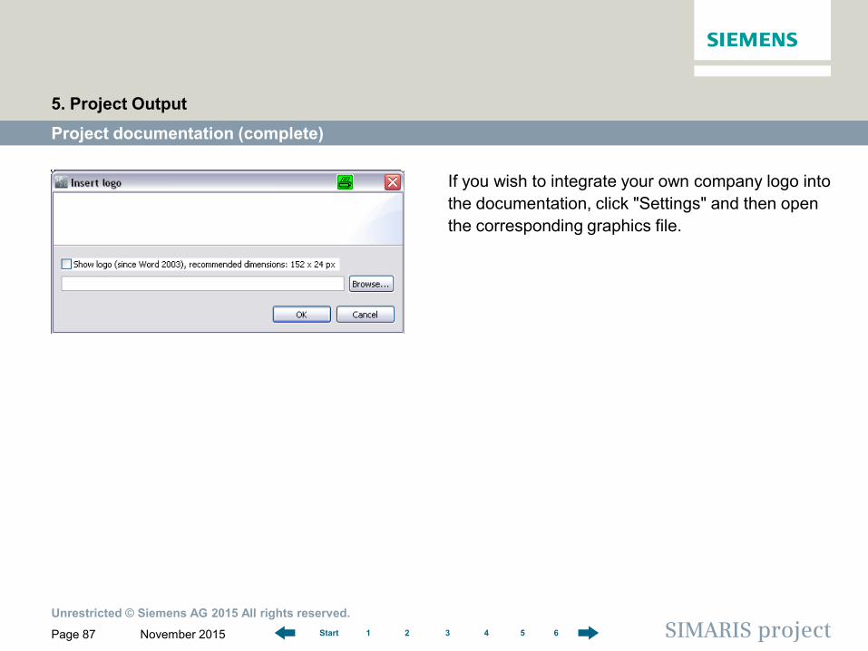
If you wish to integrate your own company logo into the documentation, click "Settings" and then open the corresponding graphics file.
Project documentation (complete)
5. Project Output
Unrestricted © Siemens AG 2015 All rights reserved.
November 2015 Page 88 SIMARIS project 1 2 3 4 5 6 Start
Project documentation (complete)
5. Project Output
Unrestricted © Siemens AG 2015 All rights reserved.
November 2015 Page 89 SIMARIS project 1 2 3 4 5 6 Start
Views
5. Project Output
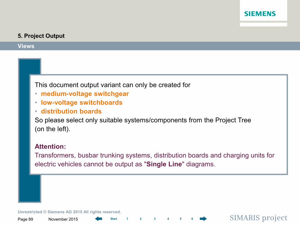
This document output variant can only be created for • medium-voltage switchgear • low-voltage switchboards • distribution boards So please select only suitable systems/components from the Project Tree (on the left). Attention: Transformers, busbar trunking systems, distribution boards and charging units for electric vehicles cannot be output as "Single Line" diagrams.
Unrestricted © Siemens AG 2015 All rights reserved.
November 2015 Page 90 SIMARIS project 1 2 3 4 5 6 Start
Views
5. Project Output
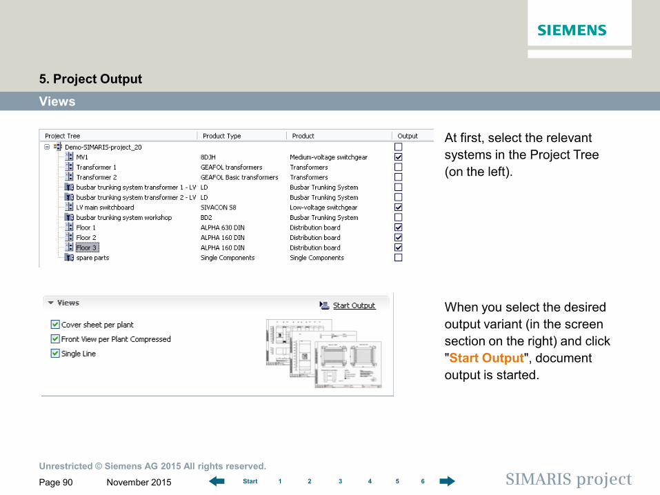
At first, select the relevant systems in the Project Tree (on the left). When you select the desired output variant (in the screen section on the right) and click "Start Output", document output is started.
Unrestricted © Siemens AG 2015 All rights reserved.
November 2015 Page 91 SIMARIS project 1 2 3 4 5 6 Start
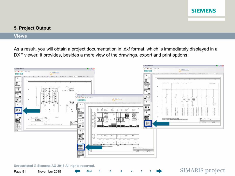
As a result, you will obtain a project documentation in .dxf format, which is immediately displayed in a DXF viewer. It provides, besides a mere view of the drawings, export and print options.
Views
5. Project Output
Unrestricted © Siemens AG 2015 All rights reserved.
November 2015 Page 92 SIMARIS project 1 2 3 4 5 6 Start
Views
5. Project Output
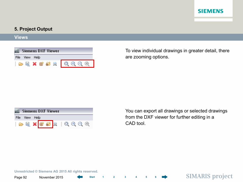
To view individual drawings in greater detail, there are zooming options.
You can export all drawings or selected drawings from the DXF viewer for further editing in a CAD tool.
Unrestricted © Siemens AG 2015 All rights reserved.
November 2015 Page 93 SIMARIS project 1 2 3 4 5 6 Start
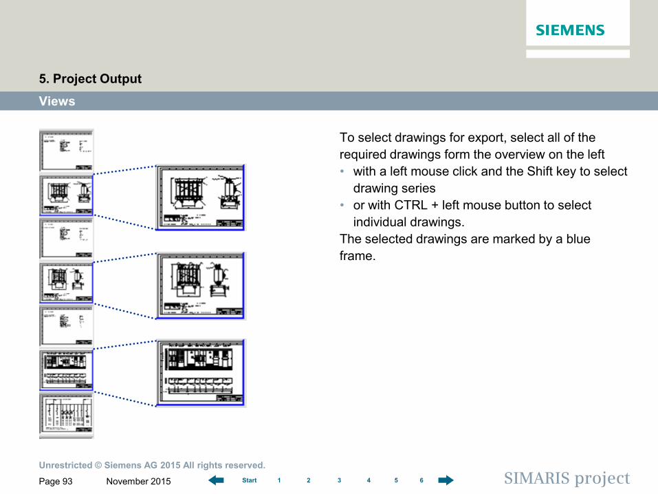
To select drawings for export, select all of the required drawings form the overview on the left • with a left mouse click and the Shift key to select
drawing series • or with CTRL + left mouse button to select
individual drawings. The selected drawings are marked by a blue frame.
Views
5. Project Output
Unrestricted © Siemens AG 2015 All rights reserved.
November 2015 Page 94 SIMARIS project 1 2 3 4 5 6 Start
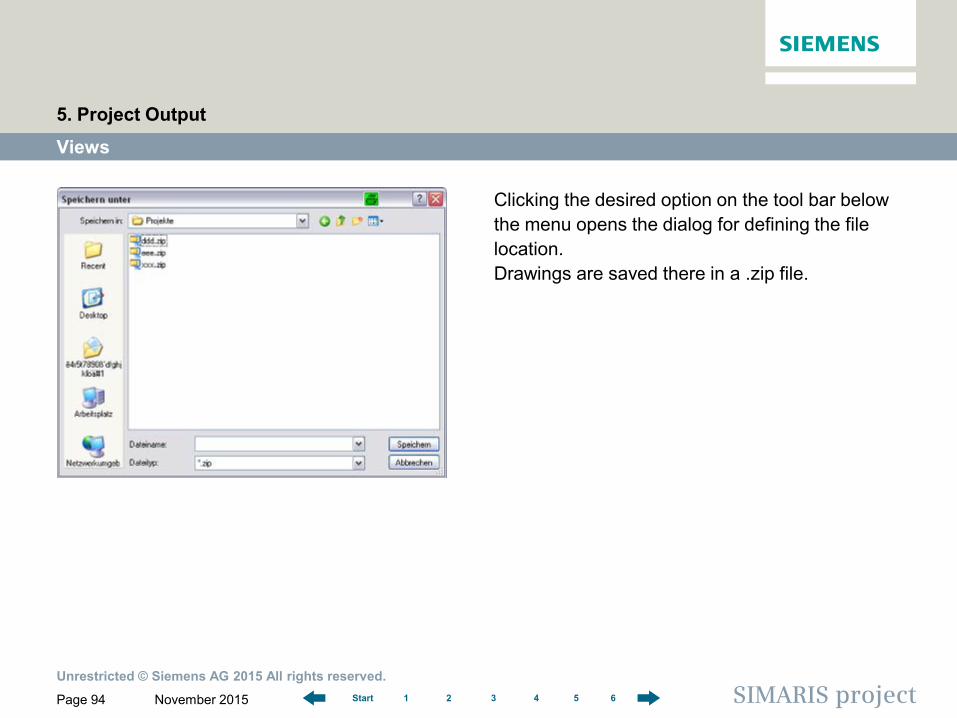
Clicking the desired option on the tool bar below the menu opens the dialog for defining the file location. Drawings are saved there in a .zip file.
Views
5. Project Output
Unrestricted © Siemens AG 2015 All rights reserved.
November 2015 Page 95 SIMARIS project 1 2 3 4 5 6 Start
Creation of technical specification
5. Project Output
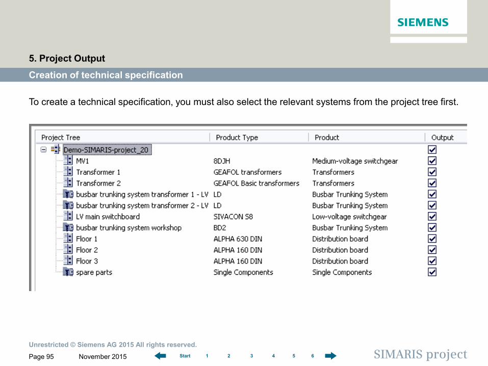
To create a technical specification, you must also select the relevant systems from the project tree first.
Unrestricted © Siemens AG 2015 All rights reserved.
November 2015 Page 96 SIMARIS project 1 2 3 4 5 6 Start
Creation of technical specification
5. Project Output
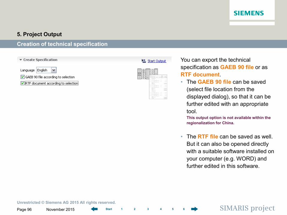
You can export the technical specification as GAEB 90 file or as RTF document. • The GAEB 90 file can be saved
(select file location from the displayed dialog), so that it can be further edited with an appropriate tool. This output option is not available within the regionalization for China.
• The RTF file can be saved as well. But it can also be opened directly with a suitable software installed on your computer (e.g. WORD) and further edited in this software.
Unrestricted © Siemens AG 2015 All rights reserved.
November 2015 Page 97 SIMARIS project 1 2 3 4 5 6 Start
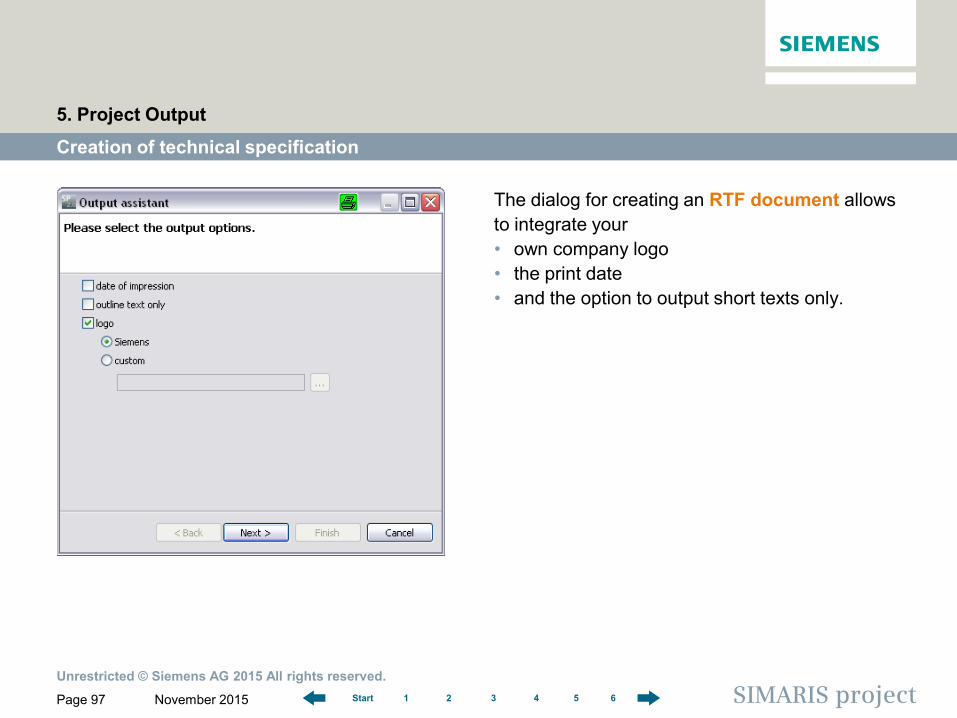
The dialog for creating an RTF document allows to integrate your • own company logo • the print date • and the option to output short texts only.
Creation of technical specification
5. Project Output
Unrestricted © Siemens AG 2015 All rights reserved.
November 2015 Page 98 SIMARIS project 1 2 3 4 5 6 Start
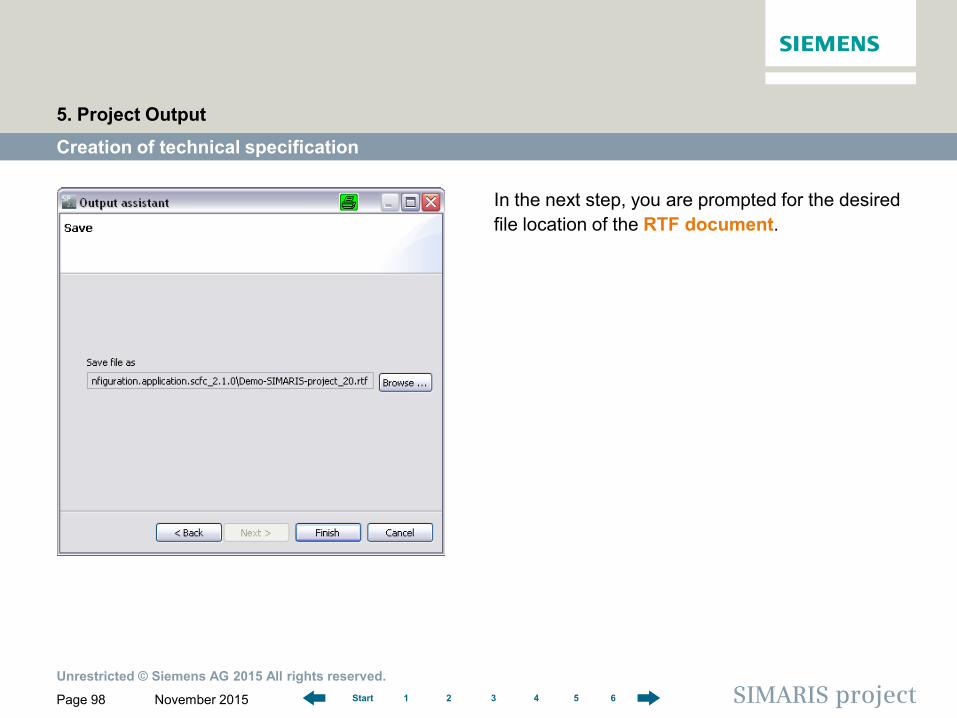
In the next step, you are prompted for the desired file location of the RTF document.
Creation of technical specification
5. Project Output
Unrestricted © Siemens AG 2015 All rights reserved.
November 2015 Page 99 SIMARIS project 1 2 3 4 5 6 Start
Creation of technical specification
5. Project Output
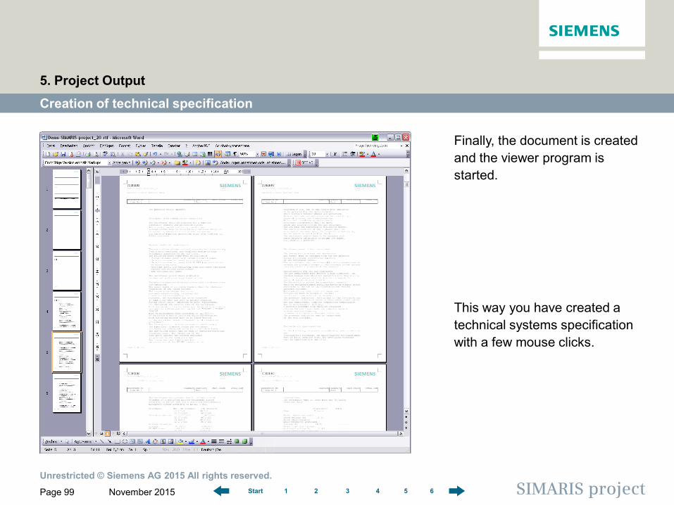
Finally, the document is created and the viewer program is started.
This way you have created a technical systems specification with a few mouse clicks.
Page 100
Software for determining the space requirements and budget for electric power distribution
1 2 3 4 5 6 Start SIMARIS project
SIMARIS project Tutorial
1 Introduction
2 Getting Started
3 Project Definition and System Planning
4 Budget
5 Project Output
6 More about SIMARIS 6 More about SIMARIS
Unrestricted © Siemens AG 2015 All rights reserved.
November 2015 Page 101 SIMARIS project 1 2 3 4 5 6 Start
In the SIMARIS project software, you will find more useful information about how to familiarize with the program and how to handle it efficiently. Click the menu item "Help" to access • the Help file • the Technical Manual for SIMARIS design and SIMARIS project. More info about the SIMARIS project and the other tools of the SIMARIS family, • SIMARIS design for network calculation and dimensioning, • SIMARIS curves for the representation of characteristic device curves and the visualisation of
parameter settings, can be obtained at www.siemens.com/simaris. On this website, you will find a whole lot of other interesting information about the SIMARIS planning tools. The contact site where you can find all local contact partners for the SIMARIS planning tools you can reach at the short link www.siemens.com/simaris/contact .
6. More about SIMARIS
Unrestricted © Siemens AG 2015 All rights reserved.
November 2015 Page 102 SIMARIS project 1 2 3 4 5 6 Start
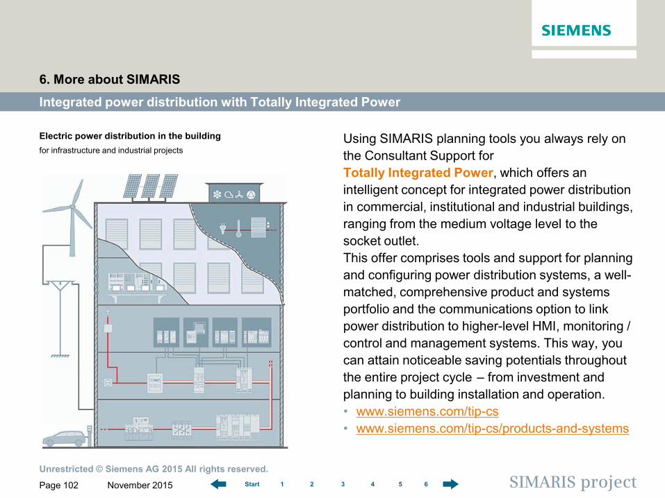
Using SIMARIS planning tools you always rely on the Consultant Support for Totally Integrated Power, which offers an intelligent concept for integrated power distribution in commercial, institutional and industrial buildings, ranging from the medium voltage level to the socket outlet. This offer comprises tools and support for planning and configuring power distribution systems, a well-matched, comprehensive product and systems portfolio and the communications option to link power distribution to higher-level HMI, monitoring / control and management systems. This way, you can attain noticeable saving potentials throughout the entire project cycle ‒ from investment and planning to building installation and operation. • www.siemens.com/tip-cs • www.siemens.com/tip-cs/products-and-systems
Integrated power distribution with Totally Integrated Power
6. More about SIMARIS
Electric power distribution in the building for infrastructure and industrial projects