silencers panels-engineering-guide
TRANSCRIPT

S E C T I O N M
Engineering GuideNoise Control
Please refer to the Price Engineer’s HVAC Handbook for more information on Noise Control.
EN
GIN
EE
RIN
G G
UID
E -
NO
ISE
CO
NT
RO
L
M-2 For more information on additional imperial and metric sizes, © Copyright Price Industries Limited 2014. please visit www.priceindustries.com or contact your local Price representative.
Noise ControlEngineering Guide
Terminology
Near FieldThe sound field immediately surrounding the source where the sound pressure is influenced by the radiation characteristics of the sound source. In this field the sound pressure and the particle velocity are out of phase. Negative Air FlowSee Reverse Air Flow.
NoiseAny unwanted sound or meaningless sound of greater than usual volume.
NR (Noise Reduction)A value that represents the difference in sound pressure level between any two points along the path of sound propagation. The unit of measurement is decibels (dB).
NRC (Noise Reduction Coefficient)A measure of the acoustical absorption performance of a material, expressed as a single value. This value is calculated by averaging the material’s sound absorption coefficients at 250, 500, 1000 and 2000 Hz and rounding to the nearest multiple of 0.05.
OctaveThe interval between two sounds having a frequency ratio of 2. There are 8 octaves on the keyboard of a standard piano.
Octave BandA segment of the frequency spectrum separated by an octave.
Pascal (Pa)A metric unit of measurement for pressure that is equivalent to one Newton per square meter (N/m2).
Pink NoiseA sound with a frequency spectrum that is flat in logarithmic scale, and has equal power in bands that are proportionally wide. When compared with white noise, the power density decreases by 3 dB per octave.
PitchA subjective sound quality that is determined by the frequency of a sound wave, or a combination of waves, that is placed on a scale extending from low to high.
Positive Air FlowSee Forward Air Flow.
Pressure Attenuation (Pa) CodeA code used to define the % of free area of a silencer cross-section. A decrease in free area typically results in an increased insertion loss and increased pressure drop across the silencer.
Pressure DropThe difference in static pressure from the inlet to the outlet of a system component.
AcousticsThe science that is related to the production, control, transmission, reception, and effects of sound.
Acoustic MediaThe sound-absorbing material used inside absorptive type silencers and plenum walls.
Ambient NoiseAn all-encompassing noise that is present in a given environment and is comprised of many sounds from many sources, with no particular sound being dominant. Also known as background noise.
A-WeightingA weighting network that is widely used, often abbreviated dBA, dB(a). It has a prescribed frequency response that bears a close relationship to loudness judgments of the human ear.
Background NoiseNoise sources other than the noise source that is of interest or being measured. Also known as ambient noise.
Breakout NoiseNoise that travels through the wall of an enclosure or duct work into an occupied space.
Broadband Noise Noise with components over a wide range of frequencies.
Decibel (dB)A unit for expressing the ratio of two amounts of acoustic signal power equal to 10 times the common logarithm (to the base 10) of this ratio.
Dynamic Insertion LossThe insertion loss at a given air flow direction and velocity. The insertion loss of a silencer varies depending on whether the sound is traveling in the same or opposite direction as the air flow. Silencer performance changes with the absolute duct velocity. The unit of measurement is dB.
FlankingIs when the walls of the ductwork on the upstream side of a silencer are readily excited into vibration, which is then transmitted through the silencer walls and internal components and re-enters the downstream duct path as noise.
Forward Air FlowA condition that exists when airborne sound and air flow are moving in the same direction. Also known as positive air flow or supply air flow.
Free FieldThe sound field where only directly radiated sound waves moving away from the sound source are present. This condition exists
when a sound source is located a large distance from reflecting surfaces, or when nearby surfaces are highly absorbent.
FrequencyThe number of times in one second that a passing wave repeats itself. The unit of frequency is Hertz ( Hz), which corresponds to 1 cycle per second.
Fundamental FrequencyThe lowest frequency in a harmonic series.
Generated NoiseThe sound power produced by air flowing through a silencer at a given velocity and direction (forward or reverse). The unit of measurement is decibels (dB).
HarmonicAn integer multiple of the fundamental frequency.
Hertz ( Hz)The unit of measurement for frequency, or the number or cycles per second.
High Transmission Loss (HTL)Occurs when a heavier material or combination of materials create a higher resistance to sound transmitting through them.
Insertion Loss (IL)The decrease in sound pressure level or sound intensity level measured at a receiver when the silencer or a sound-attenuating element is inserted into the path between the source and the receiver. The unit of measurement is decibels (dB).
IntensitySee Sound Intensity.
Intensity LevelSee Sound Intensity Level.
Media ProtectionA liner that is applied between the fiberglass media and the air stream of the silencer to protect the media from erosion due to high velocity air flow and airborne contaminates.
Module FactorA value that is used to define the width of a single module.
NC (Noise Criteria) A weighted value obtained from a series of curves that covers a spectrum of octave bands with center frequencies ranging from 63 Hz to 8000 Hz. Sound levels are plotted at each of these frequency bands, with the highest point on the NC curve, regardless of frequency, being the NC rating for the piece of equipment. These values are commonly used by manufactures to rate equipment because this system factors in the human sensitivity to each of the frequency bands. The single number value is known as the NC level.

EN
GIN
EE
RIN
G G
UID
E -
NO
ISE
CO
NT
RO
L
M-3 © Copyright Price Industries Limited 2014. For more information on additional imperial and metric sizes, please visit www.priceindustries.com or contact your local Price representative.
Terminology
Noise ControlEngineering Guide
Pure ToneA single frequency sound. A sound for which the sound pressure is a simple sinusoidal function of the time.
Random NoiseAn oscillation whose instantaneous magnitude is not specified for any given instant of time.
RC (Room Criteria)A value obtained from a series of curves that cover a spectrum of octave bands with center frequencies ranging from 16 Hz to 4000 Hz. This rating system was specifically created to establish design goals for HVAC systems, as it provides guidance for maintaining a certain level of background sound for masking. The curves are used to provide a rating of an occupied indoor space with a single number value indicated as the RC level.
Return Air FlowSee Reverse Air Flow.
Reverberant FieldThe sound field that consists of both directly radiated and reflected sound waves.
Reverse Air FlowA condition that exists when airborne sound and air flow are moving in the opposite direction. Also known as return air flow or negative air flow.
SabinA unit of measurement for acoustic absorption in relation to the absorption by one square foot of a perfect absorptive material.
SIL (Speech Interference Level)The arithmetic average of sound levels (dB) in the 500 Hz, 1000 Hz, 2000 Hz, and 4000 Hz octave bands. This rating deals with the ability of speech to be heard and understood.
Silencer BaffleA silencer component that is comprised of perforated metal and acoustic media or resonant chambers.
Silencer BankA complete silencer assembly that can contain one or multiple silencer components. The bank dimensions are the overall dimensions of the complete silencer, and typically match the duct dimensions.
Silencer ComponentA factory assembly that contains one or more baffles and may or may not be coupled with other components in the field to create a larger silencer bank.
Silencer ModuleA portion of the silencer that consists of one air path located between two acoustic
baffles. A silencer can have multiple modules within one component.
SoneA subjective unit of measurement for loudness for an average listener that is equal to the loudness of a 1000 Hz sound that has an intensity 40 dB above the listener’s threshold of hearing.
Sound(A) An oscillation in pressure, stress, particle displacement, particle velocity, etc. in an elastic or partially elastic medium, or the superposition of such propagated alterations.
(B) An auditory sensation evoked by the oscillation described above.
Sound IntensityThe amount and direction of flow of acoustic energy at a given position (W/m2).
Sound Intensity LevelThe ratio of sound intensity, which is obtained by taking ten times the common logarithm of a given sound intensity in reference to 10-12 W/m2. The unit of measurement is dB re 10-12 W/m2.
Sound PowerThe total sound energy radiated by a source per unit time. The unit of measurement is the watt (W).
Sound Power LevelAlgebraically defined as LW=10log(W/Wref) where typically Wref = 10-12 watts. This equation indicates that sound power level is ten times the logarithm (to the base 10) of the ratio of a given sound power to a reference power (typically 10-12 watts). The unit used to express sound power level is decibels in respect to the reference sound power (e.g. 84 dB re 10-12 watts).
Sound PressureThe instantaneous difference between the actual pressure produced by a sound wave and the average or barometric pressure at a given point in space. The unit of measure is typically Pascals (Pa).
Sound Pressure Level (LP)Algebraically defined as LP=20log(P/Pref) where typically Pref = 20 x 10-6 Pascal. This equation indicates that sound pressure level is twenty times the logarithm (to the base 10) of the ratio of a given sound pressure to a reference pressure (typically 20 x 10-6
Pascal). The unit used to express sound pressure level is decibels in respect to the reference sound pressure (e.g. 87 dB re 20 x 10-6 Pascal).
Sound Transmission Class (STC)A single figure rating system designed to give an estimate of the sound insulation
properties of floors, walls, ceilings, windows, doors, etc.
Static Pressure (Ps)The pressure exerted equally in all directions on a system, regardless of air flow. This can also be defined as the difference between Total Pressure (Pt) and the Velocity Pressure (Pv), expressed as Ps = Pt-Pv.
Static Pressure LossThe difference in static pressure from the inlet to the discharge of a duct element.
Static RegainAn increase in system static pressure that occurs in correlation with a decrease in velocity pressure caused by an increase in the cross-sectional area of the ductwork.
Supply Air FlowSee Forward Air Flow.
System EffectA deviation from the cataloged performance for a piece of equipment. This is caused by the difference between how the product was tested and how the product is actually installed in the system.
ToneAn intense sound that is concentrated at a single frequency and typically contains harmonics at multiples (2x, 3x, 4x, etc.) of the fundamental frequency.
Total Pressure (Pt)The combined effect of velocity pressure and the static pressure. This can also be defined as the algebraic sum of Static Pressure (Ps) and Velocity Pressure (Pv), Pt = Ps + Pv.
Transmission Loss (TL)A reduction of sound levels as a result of passage through an obstruction such as a wall, partition, or ductwork. These values are expressed with a unit of decibels (dB).
VibrationA periodic motion or displacement in a solid elastic medium.
Velocity Pressure (Pv)The pressure exerted by a moving fluid which acts only in the direction of fluid flow. This can also be defined as Pv = Pt - Ps.
WavelengthThe linear distance between two successive points of a sound wave which are separated by one period.
White NoiseA sound with a flat frequency spectrum in linear scale. It has equal power in any linear band and at any center frequency having a given bandwidth.

EN
GIN
EE
RIN
G G
UID
E -
NO
ISE
CO
NT
RO
L
M-4 For more information on additional imperial and metric sizes, © Copyright Price Industries Limited 2014. please visit www.priceindustries.com or contact your local Price representative.
Wavelength
Comparision of Wavelengths for Different Frequencies
Fundamental Concepts
What is Sound?Sound is a propagating vibrational disturbance or wave in an elastic medium (solid, liquid or gas). Sound is most commonly thought of as being transmitted in air and detected by a person’s ears.
What is Noise?Noise is defined as any unwanted or undesirable sound. While sound in general is not necessarily a problem and may even be desired in certain situations, when it is unwanted or annoying, we refer to it as noise. The proper application of Noise Control Products such as silencers and panels are discussed in this engineering guide.
FrequencyFrequency refers to the number of cycles per second of an oscillation. For example, middle C on a piano represents a pure tone at 250 Hz.
The audible frequency range for humans is about 20 Hz to 20000 Hz. This large frequency range is broken down into octave bands to make measurement and analysis more manageable. Each octave band is identified by the center frequency. The eight commonly used octave bands for HVAC noise are 63 Hz, 125 Hz, 250 Hz, 500 Hz, 1000 Hz, 2000 Hz, 4000 Hz, and 8000 Hz. For more detailed analysis, octave bands can be sub-divided into 1/3 octave bands.
Sound Pressure LevelsSound is propagated as a pressure fluctuation above and below the ambient atmospheric pressure. The amplitude of these fluctuations is proportional to how loud something is perceived to be.
The range of pressure fluctuations that can be detected by the human ear is extremely large. The decibel (dB) scale is used to describe sound pressure levels in acoustics because it reduces the scale of values to a more manageable range. Refer to the Sound Pressure Level chart (right) to see corresponding dB levels of common noises. Decibel level is defined as:
Eq.1
where:
LP = Sound pressure level p = Root mean square value of
acoustic pressure fluctuation, Pa
pref = Reference quantity defined as the threshold of hearing, 20uPa
Subjective and Objective Sound Changes
Subjective Change Objective Change
Much Louder More than 10 dB
Twice as Loud 10 dB
Louder 5 dB
Just Perceptibly Louder 3 dB
10 20 30 40 50 60 70
dB Level
80 90 100 110 120 1300
THRESH
OLD
OF H
EARIN
G
THRESH
OLD
OF PA
IN
140
200 2,000 20,000 200,000 2,000,000 20,000,000 200,000,000
µPa Level
20
Forest
Library
Office
Heavy Truck
Jack Ham
mer
Jet Take-Off
Sound Pressure Levels
Noise ControlEngineering Guide
EN
GIN
EE
RIN
G G
UID
E -
NO
ISE
CO
NT
RO
L
M-5 © Copyright Price Industries Limited 2014. For more information on additional imperial and metric sizes, please visit www.priceindustries.com or contact your local Price representative.
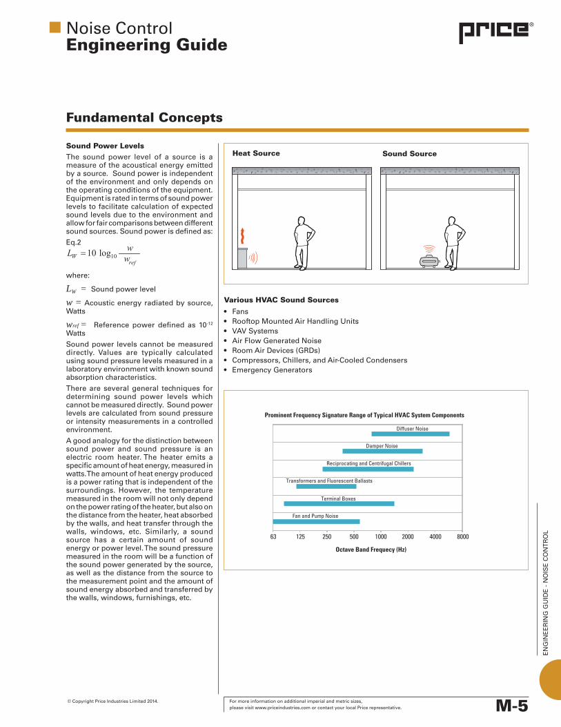
Heat Source Sound SourceSound Power LevelsThe sound power level of a source is a measure of the acoustical energy emitted by a source. Sound power is independent of the environment and only depends on the operating conditions of the equipment. Equipment is rated in terms of sound power levels to facilitate calculation of expected sound levels due to the environment and allow for fair comparisons between different sound sources. Sound power is defined as:
Eq.2
where:
LW = Sound power level w = Acoustic energy radiated by source, Watts
wref = Reference power defined as 10-12 Watts
Sound power levels cannot be measured directly. Values are typically calculated using sound pressure levels measured in a laboratory environment with known sound absorption characteristics.
There are several general techniques for determining sound power levels which cannot be measured directly. Sound power levels are calculated from sound pressure or intensity measurements in a controlled environment.
A good analogy for the distinction between sound power and sound pressure is an electric room heater. The heater emits a specific amount of heat energy, measured in watts. The amount of heat energy produced is a power rating that is independent of the surroundings. However, the temperature measured in the room will not only depend on the power rating of the heater, but also on the distance from the heater, heat absorbed by the walls, and heat transfer through the walls, windows, etc. Similarly, a sound source has a certain amount of sound energy or power level. The sound pressure measured in the room will be a function of the sound power generated by the source, as well as the distance from the source to the measurement point and the amount of sound energy absorbed and transferred by the walls, windows, furnishings, etc.
Various HVAC Sound Sources
• Fans• RooftopMountedAirHandlingUnits• VAVSystems• AirFlowGeneratedNoise• RoomAirDevices(GRDs)• Compressors,Chillers,andAir-CooledCondensers• EmergencyGenerators
Noise ControlEngineering Guide
Fundamental Concepts
EN
GIN
EE
RIN
G G
UID
E -
NO
ISE
CO
NT
RO
L
M-6 For more information on additional imperial and metric sizes, © Copyright Price Industries Limited 2014. please visit www.priceindustries.com or contact your local Price representative.
Source, Path, ReceiverA key approach to noise control is to break each problem into its fundamental components. This is the Source – Path – Receiver concept. Every noise control problem can be broken down into a source creating the noise, a path transmitting the noise, and a receiver hearing the noise. There are different options available for reducing the noise at each component. The most desirable and effective option is to treat the noise at the source. Selection of quieter equipment can eliminate many noise problems before they even begin. Treatment options along the path are the next best option and can include silencers, barriers, absorption, lagging, or other options. The last resort is typically treatment at the receiver, with hearing protection for loud occupational exposure.
Sound SourcesWherever possible, it is important to obtain source sound power levels from the supplier. The sound power levels should be derived from tested performance according to a recognized standard applicable to that equipment. Fans are commonly tested per AMCA 300 or 320, Air Handling units according to AHRI 260, terminal units per ASHRAE 130. Testing according to a recognized standard ensures that the results can be compared and evaluated between manufacturers. Estimates of power levels should only be used as a last resort where manufacturer supplied data is not available. Common sound sources in an HVAC system are fans, element generated flow noise, VAV components, and mechanical equipment.
Path Once the sources are known, the position in relation to the receiver can be determined. This will allow the path by which the noise is transmitted to be identified. It is important to note that noise typically travels through multiple paths, both airborne and structural, so possible paths must be acknowledged and evaluated appropriately. Additionally, once one path is treated, another path may become dominant and any further treatment to the first path will not be effective.
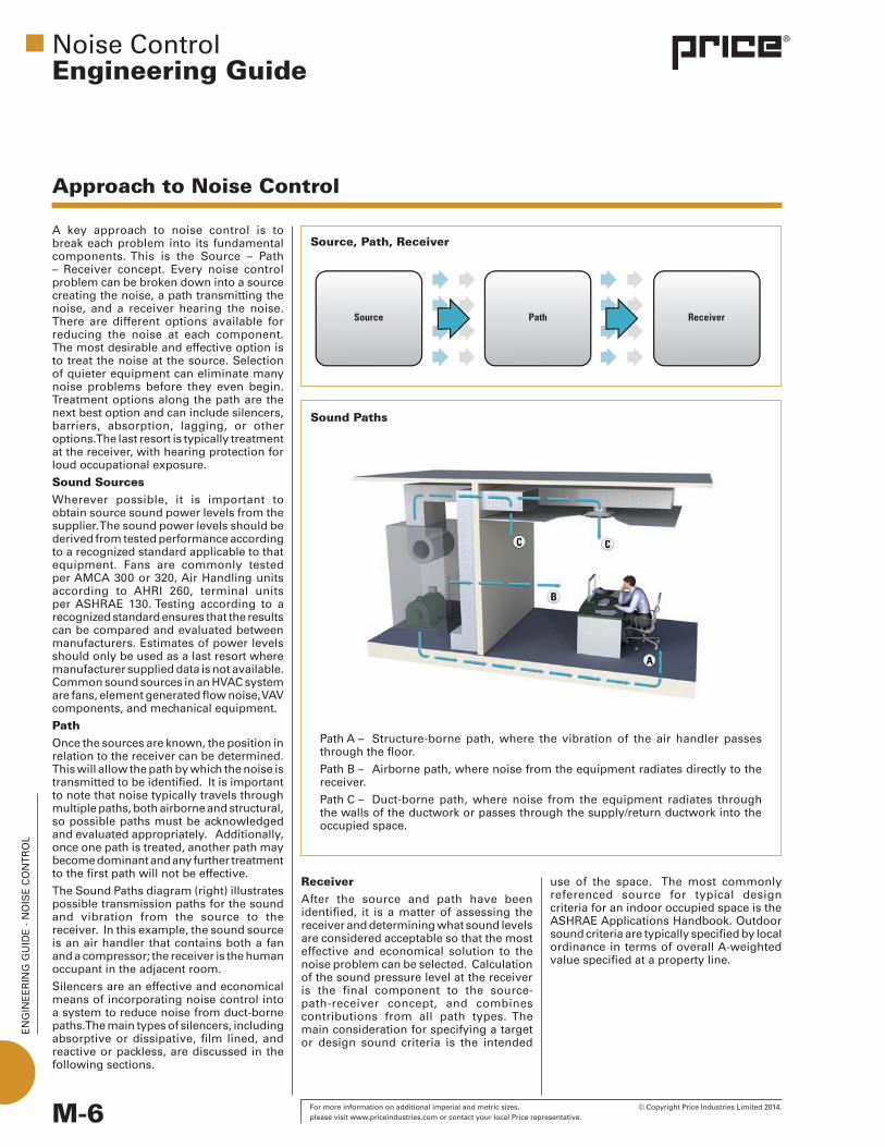
The Sound Paths diagram (right) illustrates possible transmission paths for the sound and vibration from the source to the receiver. In this example, the sound source is an air handler that contains both a fan and a compressor; the receiver is the human occupant in the adjacent room.
Silencers are an effective and economical means of incorporating noise control into a system to reduce noise from duct-borne paths. The main types of silencers, including absorptive or dissipative, film lined, and reactive or packless, are discussed in the following sections.
Noise ControlEngineering Guide
Sound Paths
Path A – Structure-borne path, where the vibration of the air handler passes through the floor.
Path B – Airborne path, where noise from the equipment radiates directly to the receiver.
Path C – Duct-borne path, where noise from the equipment radiates through the walls of the ductwork or passes through the supply/return ductwork into the occupied space.
ReceiverAfter the source and path have been identified, it is a matter of assessing the receiver and determining what sound levels are considered acceptable so that the most effective and economical solution to the noise problem can be selected. Calculation of the sound pressure level at the receiver is the final component to the source-path-receiver concept, and combines contributions from all path types. The main consideration for specifying a target or design sound criteria is the intended
Approach to Noise Control
use of the space. The most commonly referenced source for typical design criteria for an indoor occupied space is the ASHRAE Applications Handbook. Outdoor sound criteria are typically specified by local ordinance in terms of overall A-weighted value specified at a property line.
EN
GIN
EE
RIN
G G
UID
E -
NO
ISE
CO
NT
RO
L
M-7 © Copyright Price Industries Limited 2014. For more information on additional imperial and metric sizes, please visit www.priceindustries.com or contact your local Price representative.
Noise ControlEngineering Guide
Silencer Types and Applications
Absorptive Packless
Film Lined Absorptive
AbsorptiveAcoustic silencers, which are also known as dissipative silencers, utilize sound-absorbing media to attenuate sound levels. As the noise inside the duct passes through the silencer, the acoustic energy enters the baffles through the holes in the internal perforated metal liner. This perforated metal liner protects the acoustic media from being eroded by the air at high velocities, but has a large enough free area to be acoustically transparent. Once inside the baffle, the acoustic energy interacts with the absorptive media, which typically consists of strands of glass fiber. The friction between the acoustic energy and the glass fibers converts the acoustic energy into heat, thereby reducing the amount of acoustic energy and decreasing sound levels at the discharge of the silencer. For silencers that will experience high gap velocities when installed, a sheet of fiberglass cloth can be placed between the perforated metal and the glass fiber media for protection against erosion with no effect on the acoustic performance of the silencer. Typical absorptive applications include rectangular, elbow, and circular ductwork, air handling units, generator silencers, ventilation, fan plenums, and general HVAC supply, return and exhaust.
Film Lined AbsorptiveFilm lined absorptive silencers work on the same principle as the standard absorptive silencers. However, these silencers have a thin polymer film liner wrapped around the acoustic media to protect the media from airborne contaminants and moisture that may be present in the air stream of some systems. It is important to note that the addition of the film liner will negatively affect the sound absorbing capabilities of the acoustic media. To minimize these effects, a thin acoustic standoff liner is placed between the film and the perforated metal. Typical film lined silencer applications include laboratories, cleanrooms, and hospitals where contaminants and moisture in the air stream may be of concern.
PacklessPackless silencers, sometimes referred to as reactive silencers, contain no absorptive material and are constructed solely of solid and perforated sheet metal. Attenuation of sound is achieved by using multiple resonant chambers of varying size located behind the perforated metal liner. As sound passes through the silencer, the acoustic energy dissipates in a manner similar to the Helmholtz resonator concept, which results in decreased sound levels at the discharge of the silencer. Since these silencers are tuned to a narrow band of frequencies, it is more difficult to achieve significant attenuation over broadband frequencies. Packless silencers are typically specified when glass fiber media is not acceptable or when it is necessary to sterilize the entire duct system. This may include laboratories, cleanrooms, hospitals, or electronics manufacturing.
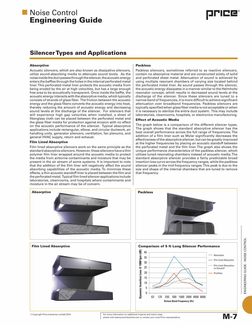
Effect of Acoustic MediaThe graph below is a comparison of the different silencer types. The graph shows that the standard absorptive silencer has the best overall performance across the full range of frequencies. The addition of a film liner such as Mylar significantly decreases the effectiveness of the absorptive silencer, but can be greatly improved at the higher frequencies by placing an acoustic standoff between the perforated metal and the film liner. The graph also shows the unique performance characteristics of the packless silencer, which utilizes tuned resonating chambers instead of acoustic media. The standard absorptive silencer provides a fairly predictable broad insertion loss curve across the frequency ranges, while the packless silencer peaks in the mid frequency ranges. This peak is due to the size and shape of the internal chambers that are tuned to remove that frequency.
Comparison of 5 ft Long Silencer Performance

EN
GIN
EE
RIN
G G
UID
E -
NO
ISE
CO
NT
RO
L
M-8 For more information on additional imperial and metric sizes, © Copyright Price Industries Limited 2014. please visit www.priceindustries.com or contact your local Price representative.
Silencer Types and Applications
RectangularRectangular silencers are the standard for silencing noise transmitted through ductwork. Their straightforward design and relative low cost make them the first choice for the highest sound attenuation and lowest pressure drop on the air distribution system. They are available with a number of options that allow them to be integrated into any HVAC system with ease. A wide range of designs with low to high pressure drop and a large selection of media types can be applied to systems ranging from 0-2500 fpm.
ElbowElbow silencers have many of the same performance characteristics of rectangular silencers, but are extremely versatile and an excellent choice for systems where straight lengths of ductwork are not available. Elbow silencers perform at or above the levels of rectangular silencers with a small increase in pressure drop on the system, and can be configured to suit most duct sizes without the use of transitions.
CircularCircular silencers are an excellent solution when round ductwork is utilized in the system. They eliminate the need for square-to-round transitions that cause undesirable pressure drops and system effects. Circular silencers are available in a wide range of sizes which allow for varying ranges of attenuation and pressure drop.
Axial FanAxial fan silencers are designed to be close coupled to an axial fan. These silencers are engineered to provide noise attenuation at the source and improve aerodynamic performance at the inlet and discharge of the fan. The axial fan silencer’s center pod is properly sized to help reduce the pressure loss over the fan hub. A discharge axial fan silencer decelerates the air to maximize the static pressure regain.
CustomA standard silencer configuration cannot always be adapted to work in every situation. In these cases it is necessary to develop a unique silencer that meets the requirements of the application. When noise control products must be applied to a system with limited space or when the silencer is directly coupled to a fan, a custom silencer can be designed to provide the required performance. Typical custom designs include transitional silencers, T or Z shaped silencers, and silencers that require a size that is not available in the standard model line.
Noise ControlEngineering Guide
Rectangular
Elbow
Circular
Axial Fan
Custom

EN
GIN
EE
RIN
G G
UID
E -
NO
ISE
CO
NT
RO
L
M-9 © Copyright Price Industries Limited 2014. For more information on additional imperial and metric sizes, please visit www.priceindustries.com or contact your local Price representative.
Silencer Types and Applications
Noise ControlEngineering Guide
Air Transfer ProductsAir transfer silencers allow air to move from one area to another without compromising the acoustic integrity of the wall. These silencers are typically not ducted and are part of the wall construction.
Cross-TalkCross-talk silencers are used to transfer air to adjacent areas while providing the necessary attenuation to prevent transferring unwanted noise. They are commonly used to prevent speech intrusion into adjacent rooms. Cross-talk silencers are manufactured in a variety of configurations that can be used to solve many different acoustic air transfer problems.
Thin Line Return DissipaterThin line return dissipaters utilize multiple baffles filled with acoustic media that are staggered in a frame that is only 4 in. thick. They are great for applications in place of standard transfer grilles to reduce sound transmission between adjacent spaces or to attenuate return air noise.
Acoustic LouversAcoustic louvers can be used for allowing air to flow through an opening while providing the necessary sound attenuation. Acoustic louvers use acoustic media to absorb the sound energy and a perforated metal to protect the media from erosion by the air flow. Acoustic louvers are designed to be aerodynamic to help minimize the pressure drop.
Acoustic Panels and EnclosuresUsedforcontrollingexcessivenoisefromequipment, Price acoustic panels and enclosures are available in many shapes and sizes to meet specific noise reduction requirements. Typical applications include barrier systems, custom enclosures, and inlet and exhaust plenums; with applications ranging from large units for gas turbines to smaller units for pumps, motors, compressors or any other unwanted HVAC or industrial noise source.
Cross-Talk
Thin Line Return Dissipater
Acoustic Louvers
Acoustic Panels and Enclosures

EN
GIN
EE
RIN
G G
UID
E -
NO
ISE
CO
NT
RO
L
M-10 For more information on additional imperial and metric sizes, © Copyright Price Industries Limited 2014. please visit www.priceindustries.com or contact your local Price representative.
Noise ControlEngineering Guide
CasingThe outer shell of the silencer is constructed of solid sheet metal. This shell can be fabricated from various materials and range in thickness from 24 gauge to 10 gauge. A heavier gauge casing is often used to improve the transmission loss properties of the silencer, which reduces the amount of noise that can breakout through the walls of the silencer and enter into the occupied space. A heavier gauge material will also make the silencer more robust to provide resistance to the elements or other sources. Standard silencer casings are manufactured from hot-dipped galvanized steel with a coatingweightofG-90 (G-90designatesa zinc coating of .90 oz/ft2). Additional available casing materials are 304 and 316 stainless steel and aluminum.
Perforated LinerThe perforated material on the interior of the silencer is specially designed to provide protection to the internal acoustic media, but is acoustically transparent, allowing sound energy to penetrate the acoustic media.
Acoustic Media In absorptive silencers the acoustic media is the internal fibrous material that absorbs energy from the sound waves as they pass through the silencer. The selection of this material may be based on requirements including local and international standards, the application parameters, and the customer’s preference.
LinerVarious silencer liner materials can be installed depending on the application. Liners like fiberglass cloth are used to protect the internal acoustic media from erosion in applications with high velocity air flow. Polymer film liners such as Mylar or Tedlar can be used to protect against moisture or other contaminants that may be found in the air. It should be noted that a fiberglass cloth liner will not affect the acoustic performance of the media, while liners such as Mylar will cause decreased insertion loss levels.
Acoustic StandoffAcoustic standoff is required in silencers with film liners in order to improve the performance of the unit. By providing a gap between the perforated liner and the film liner, the acoustic standoff greatly increases the absorptive characteristics of film lined silencers.
Construction StandardsAll components used in the construction of Price acoustical products conform to ASTME84,UL723,andNFPA255foraflamespread classification of 25 and a smoke development rating of 50.
Silencer Construction
Casing
Perforated Liner
AcousticMedia
AcousticStandoff
Liner
EN
GIN
EE
RIN
G G
UID
E -
NO
ISE
CO
NT
RO
L
M-11 © Copyright Price Industries Limited 2014. For more information on additional imperial and metric sizes, please visit www.priceindustries.com or contact your local Price representative.
Silencer Dimensional Considerations
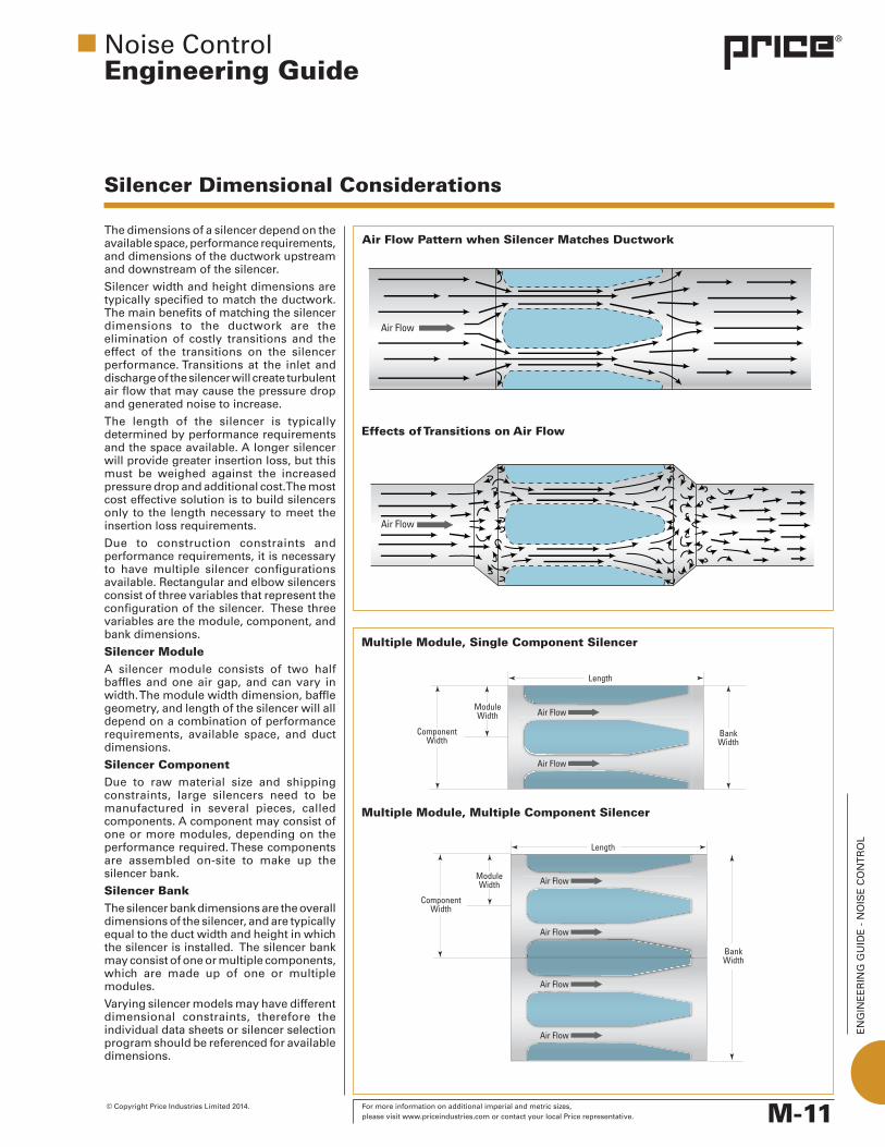
The dimensions of a silencer depend on the available space, performance requirements, and dimensions of the ductwork upstream and downstream of the silencer.
Silencer width and height dimensions are typically specified to match the ductwork. The main benefits of matching the silencer dimensions to the ductwork are the elimination of costly transitions and the effect of the transitions on the silencer performance. Transitions at the inlet and discharge of the silencer will create turbulent air flow that may cause the pressure drop and generated noise to increase.
The length of the silencer is typically determined by performance requirements and the space available. A longer silencer will provide greater insertion loss, but this must be weighed against the increased pressure drop and additional cost. The most cost effective solution is to build silencers only to the length necessary to meet the insertion loss requirements.
Due to construction constraints and performance requirements, it is necessary to have multiple silencer configurations available. Rectangular and elbow silencers consist of three variables that represent the configuration of the silencer. These three variables are the module, component, and bank dimensions.
Silencer ModuleA silencer module consists of two half baffles and one air gap, and can vary in width. The module width dimension, baffle geometry, and length of the silencer will all depend on a combination of performance requirements, available space, and duct dimensions.
Silencer Component Due to raw material size and shipping constraints, large silencers need to be manufactured in several pieces, called components. A component may consist of one or more modules, depending on the performance required. These components are assembled on-site to make up the silencer bank.
Silencer Bank The silencer bank dimensions are the overall dimensions of the silencer, and are typically equal to the duct width and height in which the silencer is installed. The silencer bank may consist of one or multiple components, which are made up of one or multiple modules.
Varying silencer models may have different dimensional constraints, therefore the individual data sheets or silencer selection program should be referenced for available dimensions.
Air Flow Pattern when Silencer Matches Ductwork
Noise ControlEngineering Guide
Multiple Module, Single Component Silencer
Multiple Module, Multiple Component Silencer
Effects of Transitions on Air Flow
EN
GIN
EE
RIN
G G
UID
E -
NO
ISE
CO
NT
RO
L
M-12 For more information on additional imperial and metric sizes, © Copyright Price Industries Limited 2014. please visit www.priceindustries.com or contact your local Price representative.
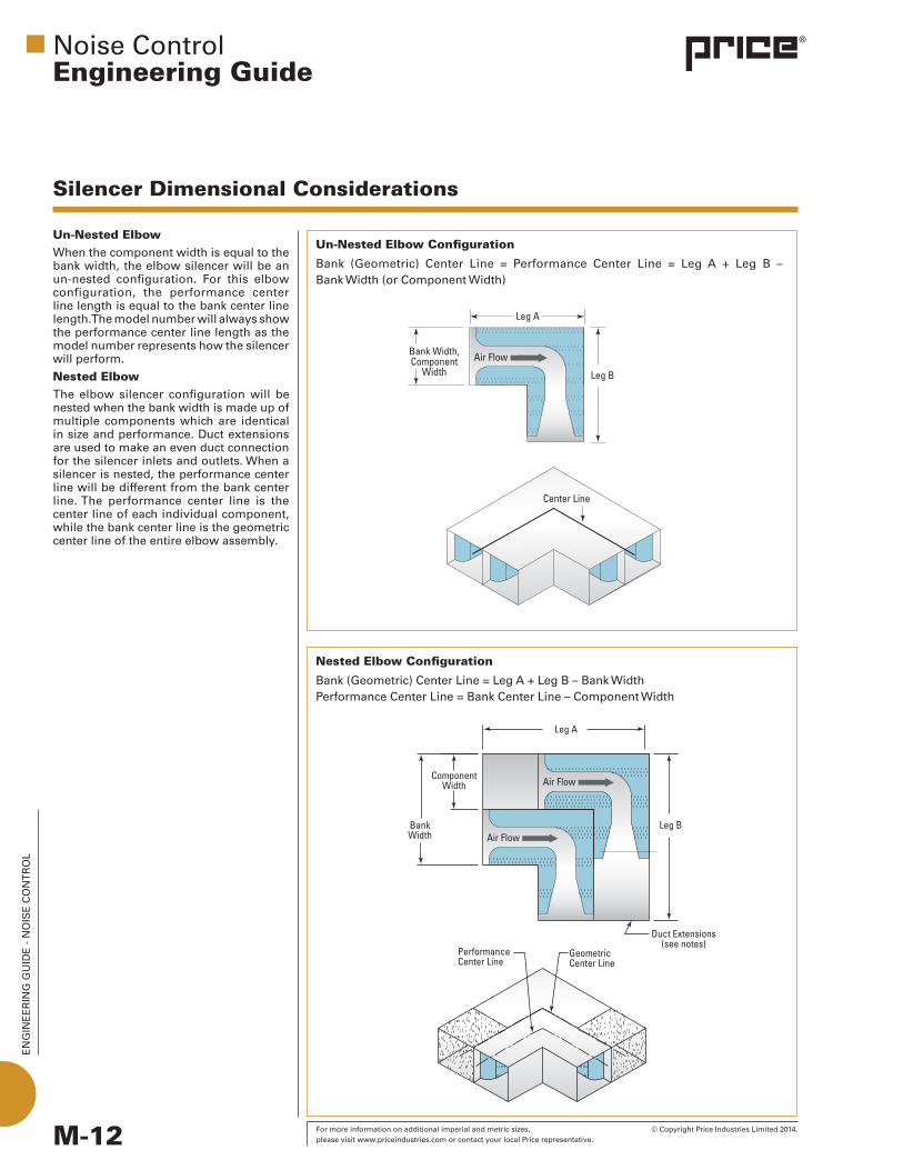
Un-Nested Elbow When the component width is equal to the bank width, the elbow silencer will be an un-nested configuration. For this elbow configuration, the performance center line length is equal to the bank center line length. The model number will always show the performance center line length as the model number represents how the silencer will perform.
Nested Elbow The elbow silencer configuration will be nested when the bank width is made up of multiple components which are identical in size and performance. Duct extensions are used to make an even duct connection for the silencer inlets and outlets. When a silencer is nested, the performance center line will be different from the bank center line. The performance center line is the center line of each individual component, while the bank center line is the geometric center line of the entire elbow assembly.
Un-Nested Elbow Configuration
Bank (Geometric) Center Line = Performance Center Line = Leg A + Leg B – Bank Width (or Component Width)
Nested Elbow Configuration
Bank(Geometric)CenterLine=LegA+LegB–BankWidth Performance Center Line = Bank Center Line – Component Width
Noise ControlEngineering Guide
Silencer Dimensional Considerations
EN
GIN
EE
RIN
G G
UID
E -
NO
ISE
CO
NT
RO
L
M-13 © Copyright Price Industries Limited 2014. For more information on additional imperial and metric sizes, please visit www.priceindustries.com or contact your local Price representative.
Testing Noise Control Products
Noise ControlEngineering Guide
Test standards are published procedures and requirements for performing a specific measurement or procedure. These are consensus based documents developed and typically written by a committee formed by people who are familiar with and interested in the specific measurement procedure. These documents are typically administered by independent, not-for-profit groups such as ASTM International, ASHRAE, ANSI, SAE, ISO, and others. Many of these groups are open to any interested party who would like to participate in the standards development process.
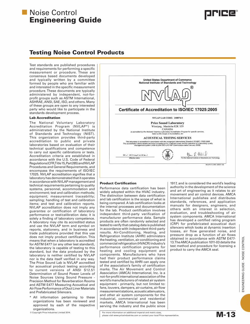
Lab AccreditationThe National Voluntary Laboratory Accreditation Program (NVLAP*) is administrated by the National Institute of Standards and Technology (NIST). This organization provides third-party accreditation to public and private laboratories based on evaluation of their technical qualifications and competence to carry out specific calibrations or tests. Accreditation criteria are established in accordancewiththeU.S.CodeofFederalRegulations (CFR, Title 15, Part 285) and NVLAP ProceduresandGeneralRequirements,andencompass the requirements of ISO/IEC 17025. NVLAP accreditation signifies that a laboratory has demonstrated that it operates in accordance with NVLAP management and technical requirements pertaining to quality systems, personnel, accommodation and environment; test and calibration methods; equipment; measurement traceability; sampling; handling of test and calibration items; and test and calibration reports. NVLAP accreditation does not imply any guarantee or certification of laboratory performance or test/calibration data; it is solely a finding of laboratory competence. A laboratory may cite its accredited status and use the NVLAP term and symbol on reports, stationery, and in business and trade publications provided that this use does not imply product certification. This means that when a laboratory is accredited for ASTM E477 (or any other test standard), the laboratory is capable of testing to this standard, but the data produced by the laboratory is neither certified by NVLAP nor is the data itself verified in any way. The Price Sound Lab is NVLAP accredited for acoustical product testing according to current versions of ANSI S12.51 Determination of Sound Power Levels of Noise Sources Using Sound Pressure -Precision Method for Reverberation Rooms and ASTM E477 Measuring Acoustical and Air Flow Performance of Duct Liner Materials and Prefabricated Silencers.
* All information pertaining to these organizations has been reviewed and approved by each of the respective organizations.
Product Certification Performance data certification has been widely adopted within the HVAC industry. The distinction between data certification and lab certification is the scope of what is being compared. A lab certification looks at the internal processes and documentation for the lab. Product certification involves independent third-party verification of manufacturer performance data. Sample products are often randomly selected and tested to verify that catalog data is published in accordance with independent third-party results. Air-Conditioning, Heating, and Refrigeration Institute (AHRI) administers the heating, ventilation, air conditioning and commercial refrigeration (HVACR) industry’s performance certification programs for heating and cooling equipment and components. Manufacturers who have had their product performance claims tested and certified by AHRI can apply one of the association’s family of certification marks. The Air Movement and Control Association (AMCA) International, Inc. is a not-for-profit international association of the world’s manufacturers of related air system equipment - primarily, but not limited to: fans, louvers, dampers, air curtains, air flow measurement stations, acoustic attenuators, and other air system components for the industrial, commercial and residential markets. AMCA International has been serving the industry and the public since
1917,andisconsideredtheworld’sleadingauthority in the development of the science and art of engineering as it relates to air movement and air control devices. AMCA International publishes and distributes standards, references, and application manuals for designers, engineers, and others with an interest in selection, evaluation, and troubleshooting of air system components. AMCA International has developed a certified rating program (CRP) for prefabricated acoustical duct silencers which looks at dynamic insertion losses, air flow generated noise, and pressure drop as a function of air flows obtained in accordance with ASTM E477-13. The AMCA publication 1011-03 details the test method and procedure for licensing a product to carry the AMCA seal.
EN
GIN
EE
RIN
G G
UID
E -
NO
ISE
CO
NT
RO
L
M-14 For more information on additional imperial and metric sizes, © Copyright Price Industries Limited 2014. please visit www.priceindustries.com or contact your local Price representative.
1
2
3
Air Transfer Silencer Test MethodThere is currently no test method established for air transfer silencers. The performance data for these products is typically reported as noise reduction or transmission loss. These silencers are installed as part of a larger assembly, with the percentage of the transfer opening determining the effect on the overall transmission loss of the installed wall.
Acoustic louvers are typically tested and rated by AMCA according to AMCA 500L for air leakage, pressure drop, and water penetration. Acoustical louvers are typically testedaccording toASTME90 forsoundtransmission loss. The performance is often reported as a noise reduction to account for the louver being installed in a free field environment versus a reverberant test environment.
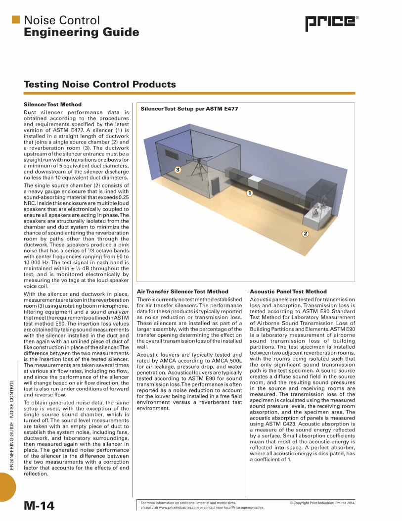
Silencer Test MethodDuct silencer performance data is obtained according to the procedures and requirements specified by the latest version of ASTM E477. A silencer (1) is installed in a straight length of ductwork that joins a single source chamber (2) and a reverberation room (3). The ductwork upstream of the silencer entrance must be a straight run with no transitions or elbows for a minimum of 5 equivalent duct diameters, and downstream of the silencer discharge no less than 10 equivalent duct diameters.
The single source chamber (2) consists of a heavy gauge enclosure that is lined with sound-absorbing material that exceeds 0.25 NRC. Inside this enclosure are multiple loud speakers that are electronically coupled to ensure all speakers are acting in phase. The speakers are structurally isolated from the chamber and duct system to minimize the chance of sound entering the reverberation room by paths other than through the ductwork. These speakers produce a pink noise that has a series of 1/3 octave bands with center frequencies ranging from 50 to 10 000 Hz. The test signal in each band is maintained within ± ½ dB throughout the test, and is monitored electronically by measuring the voltage at the loud speaker voice coil.
With the silencer and ductwork in place, measurements are taken in the reverberation room (3) using a rotating boom microphone, filtering equipment and a sound analyzer that meet the requirements outlined in ASTM testmethodE90.Theinsertionlossvaluesare obtained by taking sound measurements with the silencer installed in the duct and then again with an unlined piece of duct of like construction in place of the silencer. The difference between the two measurements is the insertion loss of the tested silencer. The measurements are taken several times at various air flow rates, including no flow, and since the performance of the silencer will change based on air flow direction, the test is also run under conditions of forward and reverse flow.
To obtain generated noise data, the same setup is used, with the exception of the single source sound chamber, which is turned off. The sound level measurements are taken with an empty piece of duct to establish the system noise, including fans, ductwork, and laboratory surroundings, then measured again with the silencer in place. The generated noise performance of the silencer is the difference between the two measurements with a correction factor that accounts for the effects of end reflection.
Testing Noise Control Products
Noise ControlEngineering Guide
Acoustic Panel Test MethodAcoustic panels are tested for transmission loss and absorption. Transmission loss is tested according toASTME90StandardTest Method for Laboratory Measurement of Airborne Sound Transmission Loss of BuildingPartitionsandElements.ASTME90is a laboratory measurement of airborne sound transmission loss of building partitions. The test specimen is installed between two adjacent reverberation rooms, with the rooms being isolated such that the only significant sound transmission path is the test specimen. A sound source creates a diffuse sound field in the source room, and the resulting sound pressures in the source and receiving rooms are measured. The transmission loss of the specimen is calculated using the measured sound pressure levels, the receiving room absorption, and the specimen area. The acoustic absorption of panels is measured using ASTM C423. Acoustic absorption is a measure of the sound energy reflected by a surface. Small absorption coefficients mean that most of the acoustic energy is reflected into space. A perfect absorber, where all acoustic energy is dissipated, has a coefficient of 1.
Silencer Test Setup per ASTM E477
EN
GIN
EE
RIN
G G
UID
E -
NO
ISE
CO
NT
RO
L
M-15 © Copyright Price Industries Limited 2014. For more information on additional imperial and metric sizes, please visit www.priceindustries.com or contact your local Price representative.
Testing Noise Control Products
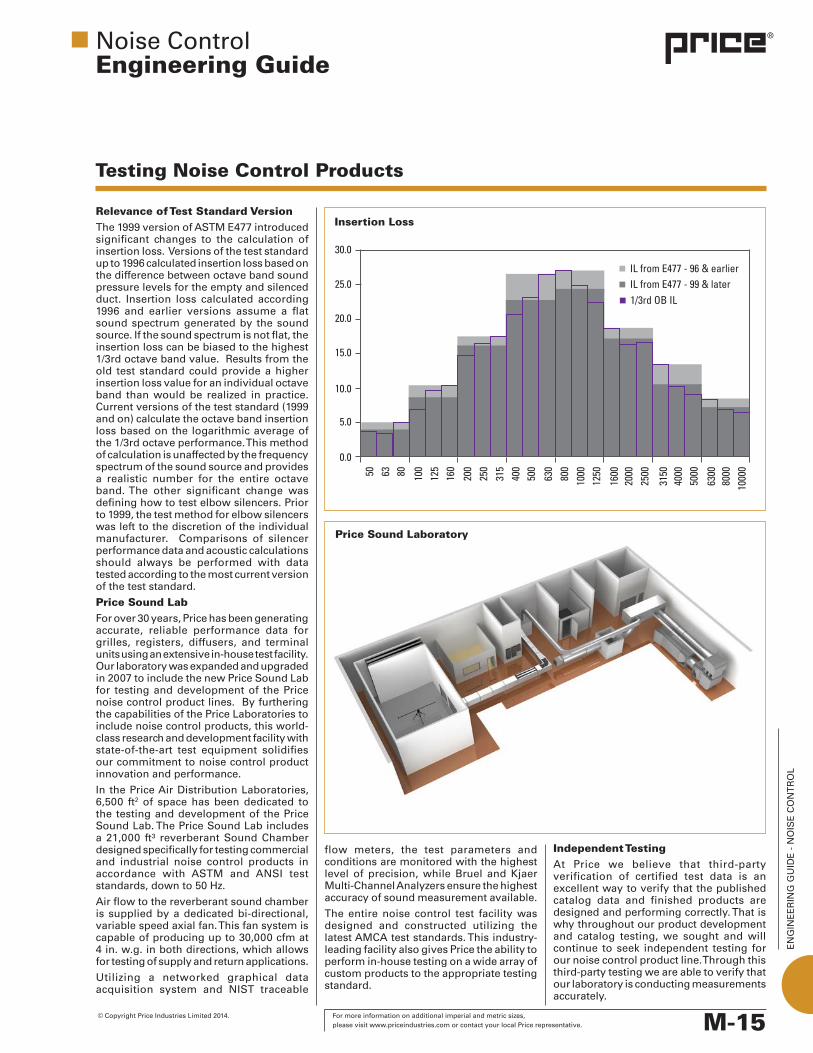
Relevance of Test Standard VersionThe1999versionofASTME477introducedsignificant changes to the calculation of insertion loss. Versions of the test standard upto1996calculatedinsertionlossbasedonthe difference between octave band sound pressure levels for the empty and silenced duct. Insertion loss calculated according 1996 and earlier versions assume a flatsound spectrum generated by the sound source. If the sound spectrum is not flat, the insertion loss can be biased to the highest 1/3rd octave band value. Results from the old test standard could provide a higher insertion loss value for an individual octave band than would be realized in practice. Currentversionsoftheteststandard(1999and on) calculate the octave band insertion loss based on the logarithmic average of the 1/3rd octave performance. This method of calculation is unaffected by the frequency spectrum of the sound source and provides a realistic number for the entire octave band. The other significant change was defining how to test elbow silencers. Prior to1999,thetestmethodforelbowsilencerswas left to the discretion of the individual manufacturer. Comparisons of silencer performance data and acoustic calculations should always be performed with data tested according to the most current version of the test standard.
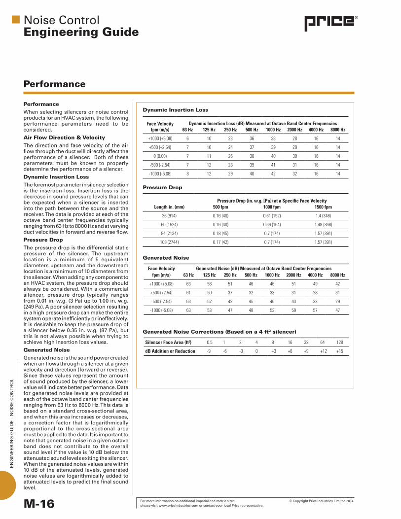
Price Sound Lab For over 30 years, Price has been generating accurate, reliable performance data for grilles, registers, diffusers, and terminal units using an extensive in-house test facility. Our laboratory was expanded and upgraded in 2007 to include the new Price Sound Lab for testing and development of the Price noise control product lines. By furthering the capabilities of the Price Laboratories to include noise control products, this world-class research and development facility with state-of-the-art test equipment solidifies our commitment to noise control product innovation and performance.
In the Price Air Distribution Laboratories, 6,500 ft2 of space has been dedicated to the testing and development of the Price Sound Lab. The Price Sound Lab includes a 21,000 ft³ reverberant Sound Chamber designed specifically for testing commercial and industrial noise control products in accordance with ASTM and ANSI test standards, down to 50 Hz.
Air flow to the reverberant sound chamber is supplied by a dedicated bi-directional, variable speed axial fan. This fan system is capable of producing up to 30,000 cfm at 4 in. w.g. in both directions, which allows for testing of supply and return applications.
Utilizing a networked graphical dataacquisition system and NIST traceable
flow meters, the test parameters and conditions are monitored with the highest level of precision, while Bruel and Kjaer Multi-Channel Analyzers ensure the highest accuracy of sound measurement available.
The entire noise control test facility was designed and constructed utilizing the latest AMCA test standards. This industry-leading facility also gives Price the ability to perform in-house testing on a wide array of custom products to the appropriate testing standard.
Noise ControlEngineering Guide
Price Sound Laboratory
Independent TestingAt Price we believe that third-party verification of certified test data is an excellent way to verify that the published catalog data and finished products are designed and performing correctly. That is why throughout our product development and catalog testing, we sought and will continue to seek independent testing for our noise control product line. Through this third-party testing we are able to verify that our laboratory is conducting measurements accurately.
Insertion Loss
EN
GIN
EE
RIN
G G
UID
E -
NO
ISE
CO
NT
RO
L
M-16 For more information on additional imperial and metric sizes, © Copyright Price Industries Limited 2014. please visit www.priceindustries.com or contact your local Price representative.
PerformanceWhen selecting silencers or noise control products for an HVAC system, the following performance parameters need to be considered.
Air Flow Direction & VelocityThe direction and face velocity of the air flow through the duct will directly affect the performance of a silencer. Both of these parameters must be known to properly determine the performance of a silencer.
Dynamic Insertion LossThe foremost parameter in silencer selection is the insertion loss. Insertion loss is the decrease in sound pressure levels that can be expected when a silencer is inserted into the path between the source and the receiver. The data is provided at each of the octave band center frequencies typically ranging from 63 Hz to 8000 Hz and at varying duct velocities in forward and reverse flow.
Pressure DropThe pressure drop is the differential static pressure of the silencer. The upstream location is a minimum of 5 equivalent diameters upstream and the downstream location is a minimum of 10 diameters from the silencer. When adding any component to an HVAC system, the pressure drop should always be considered. With a commercial silencer, pressure drop typically ranges from 0.01 in. w.g. (3 Pa) up to 1.00 in. w.g. (249Pa).Apoorsilencerselectionresultingin a high pressure drop can make the entire system operate inefficiently or ineffectively. It is desirable to keep the pressure drop of a silencer below 0.35 in. w.g. (87 Pa), but this is not always possible when trying to achieve high insertion loss values.
Generated Noise Generatednoiseisthesoundpowercreatedwhen air flows through a silencer at a given velocity and direction (forward or reverse). Since these values represent the amount of sound produced by the silencer, a lower value will indicate better performance. Data for generated noise levels are provided at each of the octave band center frequencies ranging from 63 Hz to 8000 Hz. This data is based on a standard cross-sectional area, and when this area increases or decreases, a correction factor that is logarithmically proportional to the cross-sectional area must be applied to the data. It is important to note that generated noise in a given octave band does not contribute to the overall sound level if the value is 10 dB below the attenuated sound levels exiting the silencer. When the generated noise values are within 10 dB of the attenuated levels, generated noise values are logarithmically added to attenuated levels to predict the final sound level.
Performance
Generated Noise
Dynamic Insertion Loss
Pressure Drop
Generated Noise Corrections (Based on a 4 ft2 silencer)
Noise ControlEngineering Guide
Face Velocity fpm (m/s)
Dynamic Insertion Loss (dB) Measured at Octave Band Center Frequencies63 Hz 125 Hz 250 Hz 500 Hz 1000 Hz 2000 Hz 4000 Hz 8000 Hz
+1000 (+5.08) 6 10 23 36 38 28 16 14
+500 (+2.54) 7 10 24 37 39 29 16 14
0 (0.00) 7 11 26 38 40 30 16 14
-500 (-2.54) 7 12 28 39 41 31 16 14
-1000 (-5.08) 8 12 29 40 42 32 16 14
Length in. (mm)Pressure Drop (in. w.g. [Pa]) at a Specific Face Velocity
500 fpm 1000 fpm 1500 fpm
36 (914) 0.16 (40) 0.61 (152) 1.4 (348)
60 (1524) 0.16 (40) 0.66 (164) 1.48 (368)
84 (2134) 0.18 (45) 0.7 (174) 1.57 (391)
108 (2744) 0.17 (42) 0.7 (174) 1.57 (391)
Face Velocity fpm (m/s)
Generated Noise (dB) Measured at Octave Band Center Frequencies63 Hz 125 Hz 250 Hz 500 Hz 1000 Hz 2000 Hz 4000 Hz 8000 Hz
+1000 (+5.08) 63 56 51 46 46 51 49 42
+500 (+2.54) 61 50 37 32 33 31 28 31
-500 (-2.54) 63 52 42 45 46 43 33 29
-1000 (-5.08) 63 53 47 48 53 59 57 47
Silencer Face Area (ft2) 0.5 1 2 4 8 16 32 64 128
dB Addition or Reduction -9 -6 -3 0 +3 +6 +9 +12 +15

EN
GIN
EE
RIN
G G
UID
E -
NO
ISE
CO
NT
RO
L
M-17 © Copyright Price Industries Limited 2014. For more information on additional imperial and metric sizes, please visit www.priceindustries.com or contact your local Price representative.
Factors Affecting Performance
Noise ControlEngineering Guide
Effect of Flow on Silencer Attenuation The direction and velocity of air flow through a silencer in reference to the direction sound is traveling will have an affect on the insertion loss performance that a silencer will provide. When insertion loss values include the effects of air flow direction and velocity it is known as dynamic insertion loss.
The terms forward flow or positive (+) flow indicate that the air is flowing through the silencer in the same direction the sound is traveling. These conditions occur in a supply air system or on the outlet of a fan.
The terms reverse flow or negative (-) flow indicate that the air is flowing through the silencer in the opposite direction of the noise. Examples of these conditions include a return air system or an exhaust application.
In reverse flow conditions, when the air flows in the opposite direction of the sound wave the effective speed of sound decreases slightly,causing the sound to take a longer period of time to travel the silencer passages. This results in improved low frequency insertion loss performance. At high frequencies, however, the attenuation decreases as the velocity profile in the silencer passage tends to focus the sound toward the center of the passage and away from the acoustic media.
The opposite is true of forward flow applications. When the air is flowing in the direction of sound propagation the result is decreased acoustic performance at low frequencies and increased performance at high frequencies.
The direction of air flow and air flow velocity can be important factors in making the best decision for the selection of a silencer. For critical noise control applications, selection software like Price All-In-One, which allows the exact air velocity to be entered and corrects the insertion loss values for the direction of flow, should always be used.
Forward Flow
Reverse Flow
Standard Ductwork
Exhaust Applications
Inside Air Handler
EN
GIN
EE
RIN
G G
UID
E -
NO
ISE
CO
NT
RO
L
M-18 For more information on additional imperial and metric sizes, © Copyright Price Industries Limited 2014. please visit www.priceindustries.com or contact your local Price representative.
Factors Affecting Performance
Noise ControlEngineering Guide
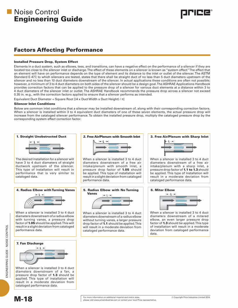
1. Straight Unobstructed Duct 2. Free Air/Plenum with Smooth Inlet
The desired installation for a silencer will have 3 to 4 duct diameters of straight ductwork upstream of the silencer. This type of installation will result in performance that is very similar to cataloged data.
When a silencer is installed 3 to 4 duct diameters downstream of a free air intake/plenum with smooth inlet, a pressure drop factor of 1.05 should be applied. This type of installation will result in a slight deviation from cataloged performance data.
3. Free Air/Plenum with Sharp Inlet
When a silencer is installed 3 to 4 duct diameters downstream of a free air intake/plenum with a sharp inlet, a pressure drop factor of 1.1 to 1.3 should be applied. This type of installation will result in a moderate deviation from cataloged performance data.
5. Radius Elbow with No Turning Vanes
When a silencer is installed 3 to 4 duct diameters downstream of a radius elbow with turning vanes, a pressure drop factor of 1.05 should be applied. This will result in a slight deviation from cataloged performance data.
When a silencer is installed 3 to 4 duct diameters downstream of a radius elbow without turning vanes, a larger pressure drop factor of 1.1 should be applied. This will result in a moderate deviation from cataloged performance data.
When a silencer is installed 3 to 4 duct diameters downstream of a mitered elbow, an even larger pressure drop factor of 1.3 should be applied. This type of installation will result in a moderate deviation from cataloged performance data.
4. Radius Elbow with Turning Vanes 6. Miter Elbow
When a silencer is installed 3 to 4 duct diameters downstream of a fan, a pressure drop factor of 1.3 should be applied. This type of installation will result in a moderate deviation from cataloged performance data.
7. Fan Discharge
Installed Pressure Drop, System Effect Elements in a duct system, such as elbows, tees, and transitions, can have a negative effect on the performance of a silencer if they are located too close to the silencer inlet or discharge. The effect of these elements on a silencer is known as “system effect.” The effect that an element will have on performance depends on the type of element and its distance to the inlet or outlet of the silencer. The ASTM Standard E-477, to which silencers are tested, states that there shall be straight duct of no less than 5 duct diameters upstream of the silencer and no less than 10 duct diameters downstream of the silencer. In actual applications these conditions are often not possible; however, a minimum of 3 to 4 duct diameters on both sides of the silencer should be a design goal. The ASHRAE Applications Handbook provides correction factors that can be applied to the pressure drop of a silencer for various duct elements at a distance within 3 to 4 duct diameters of the silencer inlet or outlet. The ASHRAE Handbook recommends the pressure drop across a silencer not exceed 0.35 in. w.g., with the correction factors applied to ensure that a silencer performs as intended.
Equivalent Duct Diameter = Square Root [(4 x Duct Width x Duct Height) / π]
Silencer Inlet ConditionsBelow are common inlet conditions that a silencer may be installed downstream of, along with their corresponding correction factors. When a silencer is installed within 3 to 4 equivalent duct diameters of one of these seven elements, the actual pressure drop will increase from the cataloged silencer performance. To obtain the installed pressure drop, multiply the cataloged pressure drop by the corresponding system effect correction factor.

EN
GIN
EE
RIN
G G
UID
E -
NO
ISE
CO
NT
RO
L
M-19 © Copyright Price Industries Limited 2014. For more information on additional imperial and metric sizes, please visit www.priceindustries.com or contact your local Price representative.
Silencer Outlet ConditionsBelow are common outlet conditions that a silencer may be installed upstream of, along with their corresponding corrections factors. When a silencer is installed within 3 to 4 equivalent duct diameters of one of these seven elements, the actual pressure drop will increase from the cataloged silencer performance. To obtain the installed pressure drop, multiply the cataloged pressure drop by the corresponding system effect correction factor.
ExampleDetermine the actual pressure drop for a rectangular silencer installed with a mitered elbow 4 duct diameters upstream and an abrupt doubling of the duct area 2 duct diameters downstream. From the catalog or software selection program, a rectangular silencer model shows a pressure drop of 0.21 in. w.g. at 2000 fpm. To determine the installed pressure drop of the silencer including the system effect, multiply the pressure drop by the corresponding correction factors.
Installed Pressure Drop = Cataloged Pressure Drop x Inlet Pressure Drop Factor x Outlet Pressure Drop Factor
Pressure drop of the rectangular Silencer = 0.21 in. w.g.
Inlet correction factor for a miter elbow = 1.3
Outlet correction factor for an abrupt doubling of duct area = 1.4
Therefore:
Installed pressure drop = 0.21 x 1.3 x 1.4 = 0.38 in. w.g.
Factors Affecting Performance
Noise ControlEngineering Guide
8. Straight Unobstructed Duct 9. Duct Doubles Area Abruptly
The desired installation for a silencer will have 3 to 4 duct diameters of straight ductwork downstream of the silencer. This type of installation will result in performance that is very similar to cataloged data.
When a silencer is installed 3 to 4 duct diameters upstream of a duct transition that abruptly doubles the cross sectional area of the duct work, a pressure drop factor of 1.4 should be applied. This type of installation will cause a large deviation from cataloged performance data.
10. Abrupt Expansion/Plenum
When a silencer is installed 3 to 4 duct diameters upstream of an abrupt expansion/plenum, a pressure drop factor of 2.0 should be applied. This type of installation will result in a large deviation from cataloged performance data.
12. Radius Elbow with No Turning Vanes
When a silencer is installed 3 to 4 duct diameters upstream of a radius elbow with turning vanes, a pressure drop factor of 1.5 should be applied. This will result in a large deviation from cataloged performance data.
When a silencer is installed 3 to 4 duct diameters upstream of a radius elbow without turning vanes, a larger pressure drop factor of 1.9 should be applied. This will result in a large deviation from cataloged performance data.
When a silencer is installed 3 to 4 duct diameters upstream of a mitered elbow, an even larger pressure drop factor of 2.0 should be applied. This will result in a large deviation from cataloged performance data.
11. Radius Elbow with Turning Vanes 13. Miter Elbow
When a silencer is installed 3 to 4 duct diameters upstream of a fan, a pressure drop factor of 1.2 to 1.4 should be applied. This type of installation will result in a moderate deviation from cataloged performance data.
14. Fan Inlet
EN
GIN
EE
RIN
G G
UID
E -
NO
ISE
CO
NT
RO
L
M-20 For more information on additional imperial and metric sizes, © Copyright Price Industries Limited 2014. please visit www.priceindustries.com or contact your local Price representative.
Noise ControlEngineering Guide
1. Inlet/Discharge of Air Handler
3. Duct Terminations
5. Close Coupled to Fan
2. Riser Branches
Location in System
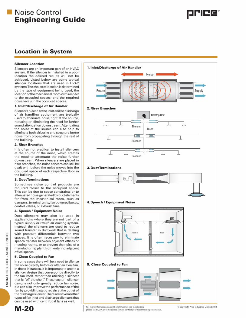
Silencer LocationSilencers are an important part of an HVAC system. If the silencer is installed in a poor location the desired results will not be achieved. Listed below are some typical silencer locations that are used in HVAC systems. The choice of location is determined by the type of equipment being used, the location of the mechanical room with respect to the occupied spaces, and the required noise levels in the occupied spaces.
1. Inlet/Discharge of Air HandlerSilencers placed at the inlet and/or discharge of air handling equipment are typically used to attenuate noise right at the source, reducing or eliminating the need for further sound attenuation downstream. Attenuating the noise at the source can also help to eliminate both airborne and structure borne noise from propagating through the rest of the building.
2. Riser BranchesIt is often not practical to install silencers at the source of the noise, which creates the need to attenuate the noise further downstream. When silencers are placed in riser branches, the noise concern can still be dealt with before the noise moves into the occupied space of each respective floor in the building.
3. Duct TerminationsSometimes noise control products are required closer to the occupied space. This can be due to space constraints or to attenuated noise generated by duct elements far from the mechanical room, such as dampers, terminal units, fan powered boxes, control valves, or exhaust fans.
4. Speech / Equipment NoiseDuct silencers may also be used in applications where they are not part of a typical supply or return air ducting system. Instead, the silencers are used to reduce sound transfer in ductwork that is dealing with pressure differentials between two spaces. It is often necessary to eliminate speech transfer between adjacent offices or meeting rooms, or to prevent the noise of a manufacturing plant from entering adjacent office spaces.
5. Close Coupled to FanIn some cases there will be a need to silence fan noise directly before or after an axial fan. In these instances, it is important to create a silencer design that corresponds directly to the fan itself, rather than utilizing a silencer that is “off the shelf.” These custom silencer designs not only greatly reduce fan noise, but can also improve the performance of the fan by providing static regain at the outlet of the discharge silencer. There are several other types of fan inlet and discharge silencers that can be used with centrifugal fans as well.
4. Speech / Equipment Noise

EN
GIN
EE
RIN
G G
UID
E -
NO
ISE
CO
NT
RO
L
M-21 © Copyright Price Industries Limited 2014. For more information on additional imperial and metric sizes, please visit www.priceindustries.com or contact your local Price representative.
Location in System
Noise ControlEngineering Guide
Breakout NoiseSound that is allowed to pass through the walls of the ductwork and the silencer casing is called breakout noise. Many things will contribute to the amount of sound that is able to break out of the silencer casing, including the shape and size of the silencer, the gauge of material used to construct the casing, and the amount of acoustic media in the walls. The transmission loss table to the right shows the transmission loss values of different rectangular silencer casing construction classes. The HTL2 casing has the highest transmission loss performance, therefore less noise will break out of the casing of a HTL2 silencer as compared to a CL1 silencer.
When trying to limit breakout noise in an HVAC system the silencer should be located as close as possible to the noise source. This will allow the silencer to attenuate the sound before it has a chance to travel through the duct system to an area where noise breakout through the duct walls will be a concern.
Mechanical Room When removing airborne sound created by fans and other equipment located in a mechanical room, the ideal location for the silencer is straddling the mechanical room wall. This location removes the unwanted sound created by the equipment as it leaves the mechanical room, which eliminates the concerns of breakout noise in occupied spaces. However, fire dampers are typically located at the wall of the mechanical room. When this is the case, the best location for the silencer is inside the mechanical room, just before the mechanical room wall. If adequate space inside the mechanical room is not available, the silencer may need to be located outside the room. In this situation the silencer should again be located at the mechanical room wall, but a heavier gauge material may be required to prevent noise from breaking out of the silencer before it is fully attenuated.
Transmission Loss
Construction Transmission Loss (Rectangular Silencers)Class Gauge 63 Hz 125 Hz 250 Hz 500 Hz 1K Hz 2K Hz 4K Hz 8K Hz
CL1 22 25 26 28 30 33 37 40 40
CL2 18 27 28 30 32 35 38 41 41
HTL1 16 28 29 31 33 36 39 42 42
HTL2 10 31 33 34 36 38 42 45 45