signaling, tdm hierarchies/sonet and switching #11 · signaling, tdm hierarchies/sonet and...
TRANSCRIPT
1Signaling ….
Signaling, TDM Hierarchies/SONET
and Switching #11
2Signaling ….
Overview
� Signaling & VoIP
� TDM Hierarchies and SONET
� Switching
� “Crossbar”
� Time division switching
� Packet switching
� Optical switching
3Signaling ….
Signaling
� Exchange of messages related to call setup, monitoring, teardown, and network management information.
� Provides command and control infrastructure for communications networks.
� End device (e.g., Telephone)-to-Switch and Between Switches
� Signaling enables the advanced features of modern communications (e.g., telephone) systems
4Signaling ….
Signaling� In-band� Out-of-band� Common channel signaling
� Reduces connect time� Increases signaling capacity� Increases flexibility� Enhanced customer services� Common Channel Interoffice Signaling (CCIS)� Common Signaling protocols
– SS #7,– RSVP,– SIP, – H.323
5Signaling ….
Requirements for signaling
� STRICT performance and reliability requirements� Fast call set up
� Always available
� To grow and provide more services signaling code must be:� Extensible
� Maintainable
� Interoperability
6Signaling ….
SS7
� Signaling System 7
�Predominant control signaling network for PSTN.
�Signaling Point: use signaling to transmit and receive control information .
�Signaling Link: interconnect signaling points.
�Signaling Transfer Point (STP): transfer signaling messages from one link to another.
�Signaling Control Point (SCP): database for SS7 network.
7Signaling ….
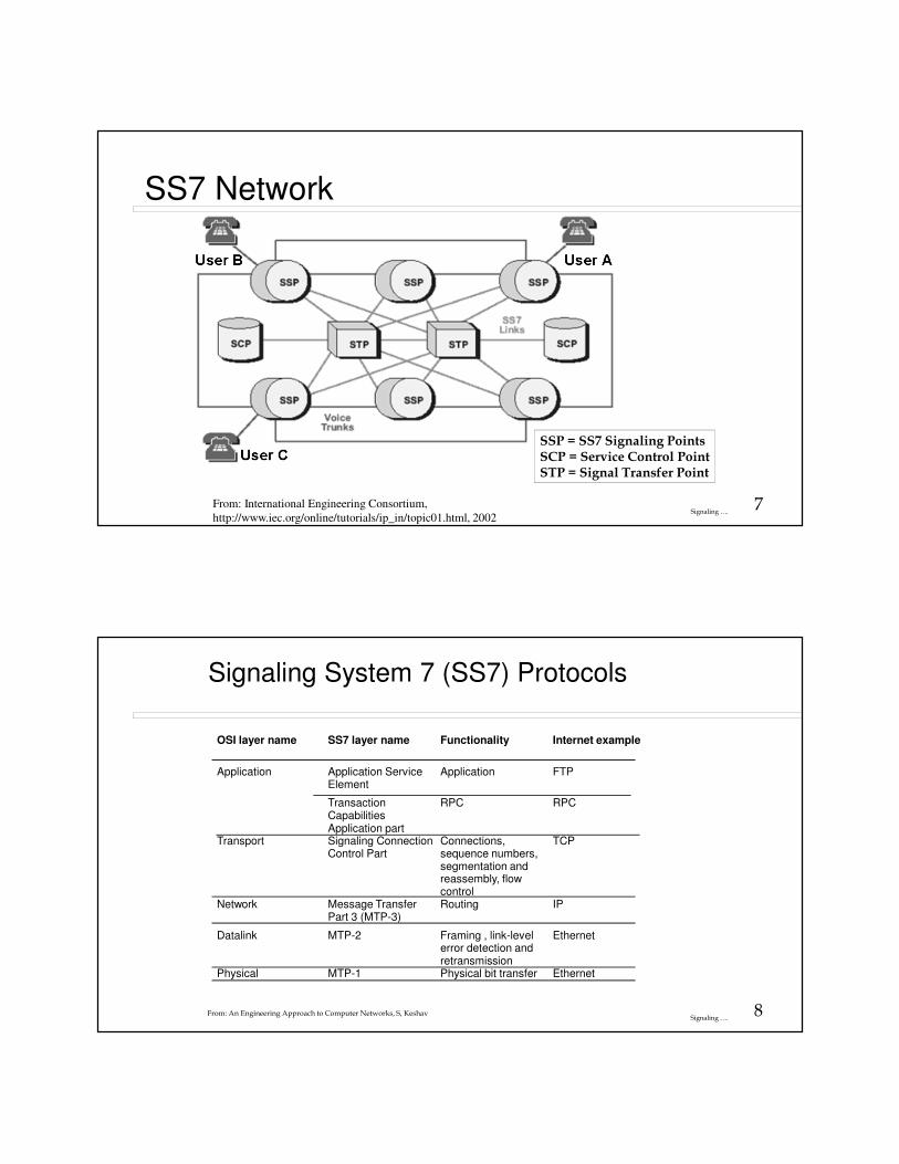
SS7 Network
From: International Engineering Consortium,
http://www.iec.org/online/tutorials/ip_in/topic01.html, 2002
SSP = SS7 Signaling PointsSCP = Service Control PointSTP = Signal Transfer Point
8Signaling ….
OSI layer name SS7 layer name Functionality Internet example
Application Application ServiceElement
Application FTP
TransactionCapabilitiesApplication part
RPC RPC
Transport Signaling ConnectionControl Part
Connections,sequence numbers,segmentation andreassembly, flowcontrol
TCP
Network Message TransferPart 3 (MTP-3)
Routing IP
Datalink MTP-2 Framing , link-levelerror detection andretransmission
Ethernet
Physical MTP-1 Physical bit transfer Ethernet
Signaling System 7 (SS7) Protocols
From: An Engineering Approach to Computer Networks, S, Keshav
9Signaling ….
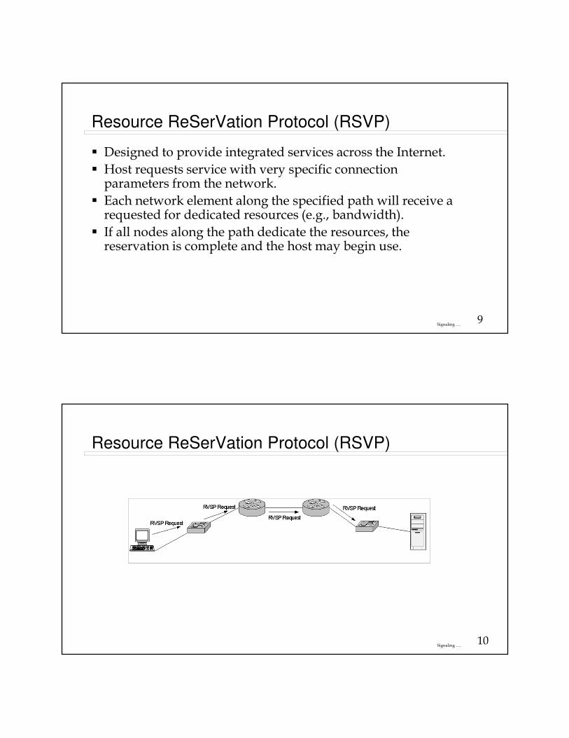
Resource ReSerVation Protocol (RSVP)
� Designed to provide integrated services across the Internet.
� Host requests service with very specific connection parameters from the network.
� Each network element along the specified path will receive a requested for dedicated resources (e.g., bandwidth).
� If all nodes along the path dedicate the resources, the reservation is complete and the host may begin use.
10Signaling ….
Resource ReSerVation Protocol (RSVP)
11Signaling ….
Voice over IP (VoIP)
� A network that transmits voice packets over IP.
� Specialized signaling protocols are used to set up and tear down calls, carry information required to locate users and negotiate capabilities.
� Voice signal is digitized, compressed and converted to IP packets.
12Signaling ….
Voice over the Internet:
Benefits
� Can place a phone call to any other internet telephony user anywhere in the world and only pay for call to local ISP
� Simplifies voice/data conferencing
� Enhanced helpdesks
� Enhanced on-line order placement
� Integration offers potential to reduce administrative cost
13Signaling ….
Voice over the Internet:
Problems
� Quality of Service� The internet is currently “best effort”
� The internet is unreliable
� Lack of standards ~~> plethora of proprietary solutions� Lack of Interoperatability
� Lack of high volume call processing capability
� 911
14Signaling ….
Session Initiation Protocol (SIP)
� Session Initiation Protocol
� Comes from IETF
� All telephone calls and video conference calls take place over the Internet
� People are identified by names or e-mail addresses, rather than by phone numbers.
� You can reach the callee, no matter where the callee roams, no matter what IP device the callee is currently using.
From Computer Networking: A Top Down Approach Featuring the Internet, 2nd edition. Jim Kurose, Keith Ross, Addison-Wesley, Copyright 1996-2002, J .F Kurose and K.W. Ross, All Rights Reserved
15Signaling ….
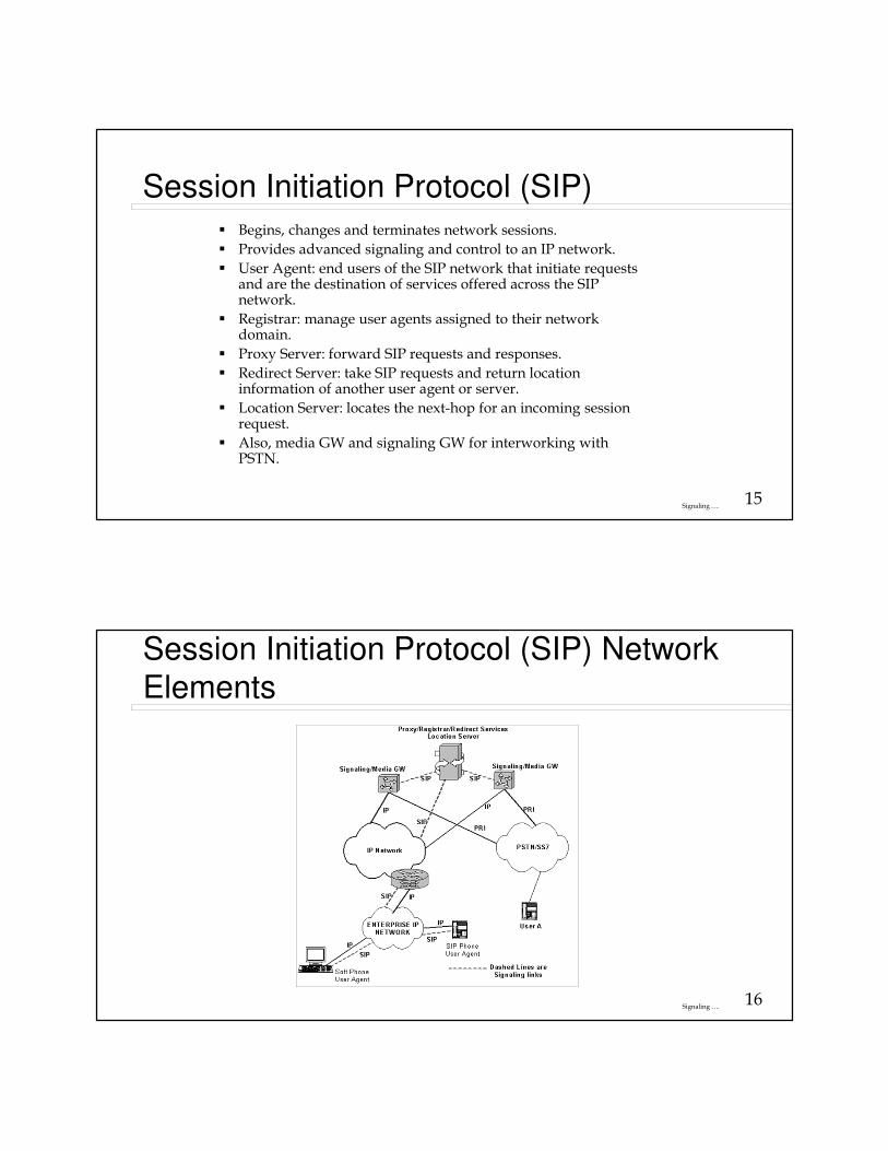
Session Initiation Protocol (SIP)� Begins, changes and terminates network sessions.
� Provides advanced signaling and control to an IP network.
� User Agent: end users of the SIP network that initiate requests and are the destination of services offered across the SIP network.
� Registrar: manage user agents assigned to their network domain.
� Proxy Server: forward SIP requests and responses.
� Redirect Server: take SIP requests and return location information of another user agent or server.
� Location Server: locates the next-hop for an incoming session request.
� Also, media GW and signaling GW for interworking with PSTN.
16Signaling ….
Session Initiation Protocol (SIP) Network
Elements
17Signaling ….
SIP Services
� Setting up a call� Provides mechanisms for
caller to let callee know she wants to establish a call
� Provides mechanisms so that caller and callee can agree on media type and encoding.
� Provides mechanisms to end call.
� Determine current IP address of callee.� Maps mnemonic
identifier to current IP address
� Call management� Add new media streams
during call
� Change encoding during call
� Invite others
� Transfer and hold calls
From Computer Networking: A Top Down Approach Featuring the Internet, 2nd edition. Jim Kurose, Keith Ross, Addison-Wesley, Copyright 1996-2002, J .F Kurose and K.W. Ross, All Rights Reserved
18Signaling ….
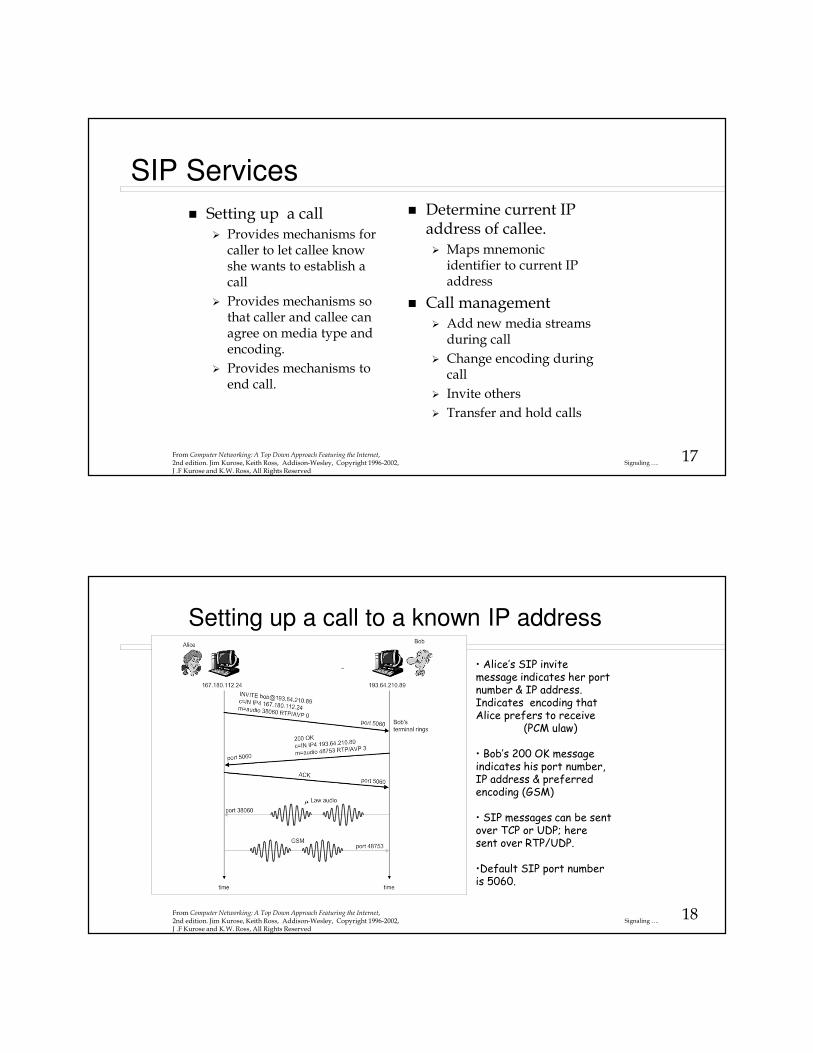
Setting up a call to a known IP address
• Alice’s SIP invite message indicates her port number & IP address. Indicates encoding that Alice prefers to receive
(PCM ulaw)
• Bob’s 200 OK message indicates his port number, IP address & preferred encoding (GSM)
• SIP messages can be sent over TCP or UDP; here sent over RTP/UDP.
•Default SIP port number is 5060.
From Computer Networking: A Top Down Approach Featuring the Internet, 2nd edition. Jim Kurose, Keith Ross, Addison-Wesley, Copyright 1996-2002, J .F Kurose and K.W. Ross, All Rights Reserved
19Signaling ….
Setting up a call (more)� Codec negotiation:
� Suppose Bob doesn’t have PCM ulaw encoder.
� Bob will instead reply with 606 Not Acceptable Reply and list encoders he can use.
� Alice can then send a new INVITE message, advertising an appropriate encoder.
� Rejecting the call
� Bob can reject with replies “busy,” “gone,” “payment required,” “forbidden”.
� Media can be sent over RTP or some other protocol.
� Signaling and media can go over different paths
From Computer Networking: A Top Down Approach Featuring the Internet, 2nd edition. Jim Kurose, Keith Ross, Addison-Wesley, Copyright 1996-2002, J .F Kurose and K.W. Ross, All Rights Reserved
20Signaling ….
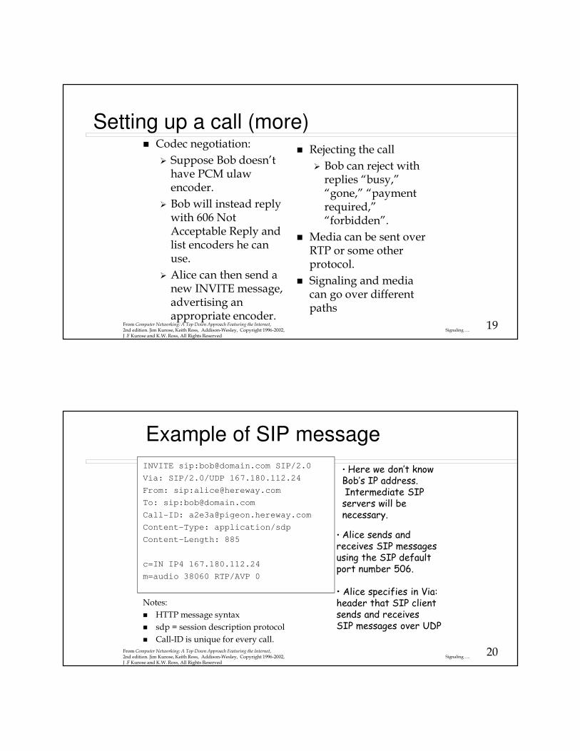
Example of SIP message
INVITE sip:[email protected] SIP/2.0
Via: SIP/2.0/UDP 167.180.112.24
From: sip:[email protected]
To: sip:[email protected]
Call-ID: [email protected]
Content-Type: application/sdp
Content-Length: 885
c=IN IP4 167.180.112.24
m=audio 38060 RTP/AVP 0
Notes:
� HTTP message syntax
� sdp = session description protocol
� Call-ID is unique for every call.
• Here we don’t know Bob’s IP address. Intermediate SIPservers will be necessary.
• Alice sends and receives SIP messages using the SIP default port number 506.
• Alice specifies in Via:header that SIP client sends and receives SIP messages over UDP
From Computer Networking: A Top Down Approach Featuring the Internet, 2nd edition. Jim Kurose, Keith Ross, Addison-Wesley, Copyright 1996-2002, J .F Kurose and K.W. Ross, All Rights Reserved
21Signaling ….
Name translation and user location
� Caller wants to call callee, but only has callee’s name or e-mail address.
� Need to get IP address of callee’s current host:� user moves around
� DNS protocol
� user has different IP devices (PC, PDA, car device)
� Result can be based on:� time of day (work, home)
� caller (don’t want boss to call you at home)
� status of callee (calls sent to voicemail when callee is already talking to someone)
Service provided by SIP servers:
� SIP registrar server
� SIP proxy server
From Computer Networking: A Top Down Approach Featuring the Internet, 2nd edition. Jim Kurose, Keith Ross, Addison-Wesley, Copyright 1996-2002, J .F Kurose and K.W. Ross, All Rights Reserved
22Signaling ….
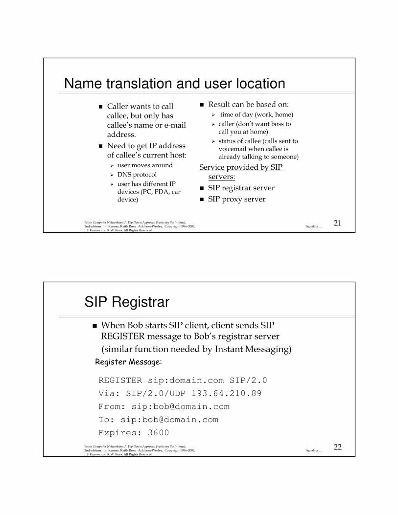
SIP Registrar
REGISTER sip:domain.com SIP/2.0
Via: SIP/2.0/UDP 193.64.210.89
From: sip:[email protected]
To: sip:[email protected]
Expires: 3600
� When Bob starts SIP client, client sends SIP REGISTER message to Bob’s registrar server
(similar function needed by Instant Messaging)
Register Message:
From Computer Networking: A Top Down Approach Featuring the Internet, 2nd edition. Jim Kurose, Keith Ross, Addison-Wesley, Copyright 1996-2002, J .F Kurose and K.W. Ross, All Rights Reserved
23Signaling ….
SIP Proxy
� Alice send’s invite message to her proxy server� contains address sip:[email protected]
� Proxy responsible for routing SIP messages to callee� possibly through multiple proxies.
� Callee sends response back through the same set of proxies.
� Proxy returns SIP response message to Alice � contains Bob’s IP address
� Note: proxy is analogous to local DNS server
From Computer Networking: A Top Down Approach Featuring the Internet, 2nd edition. Jim Kurose, Keith Ross, Addison-Wesley, Copyright 1996-2002, J .F Kurose and K.W. Ross, All Rights Reserved
24Signaling ….
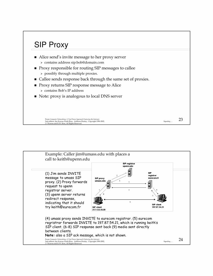
(1) Jim sends INVITEmessage to umass SIPproxy. (2) Proxy forwardsrequest to upenn registrar server. (3) upenn server returnsredirect response,indicating that it should try [email protected]
(4) umass proxy sends INVITE to eurecom registrar. (5) eurecom regristrar forwards INVITE to 197.87.54.21, which is running keith’s SIP client. (6-8) SIP response sent back (9) media sent directly between clients. Note: also a SIP ack message, which is not shown.From Computer Networking: A Top Down Approach Featuring the Internet, 2nd edition. Jim Kurose, Keith Ross, Addison-Wesley, Copyright 1996-2002, J .F Kurose and K.W. Ross, All Rights Reserved
Example: Caller [email protected] with places a call to [email protected]
25Signaling ….
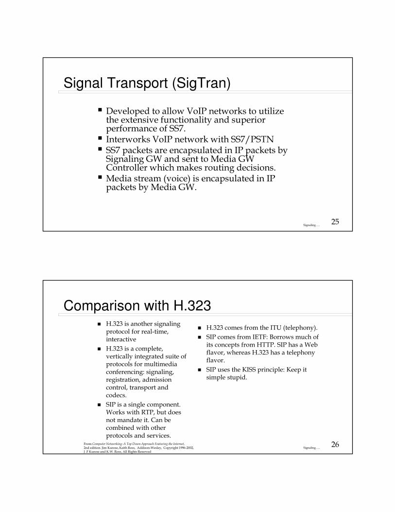
Signal Transport (SigTran)
� Developed to allow VoIP networks to utilize the extensive functionality and superior performance of SS7.
� Interworks VoIP network with SS7/PSTN� SS7 packets are encapsulated in IP packets by
Signaling GW and sent to Media GW Controller which makes routing decisions.
� Media stream (voice) is encapsulated in IP packets by Media GW.
26Signaling ….
Comparison with H.323� H.323 is another signaling
protocol for real-time, interactive
� H.323 is a complete, vertically integrated suite of protocols for multimedia conferencing: signaling, registration, admission control, transport and codecs.
� SIP is a single component. Works with RTP, but does not mandate it. Can be combined with other protocols and services.
� H.323 comes from the ITU (telephony).
� SIP comes from IETF: Borrows much of its concepts from HTTP. SIP has a Web flavor, whereas H.323 has a telephony flavor.
� SIP uses the KISS principle: Keep it simple stupid.
From Computer Networking: A Top Down Approach Featuring the Internet, 2nd edition. Jim Kurose, Keith Ross, Addison-Wesley, Copyright 1996-2002, J .F Kurose and K.W. Ross, All Rights Reserved
27Signaling ….
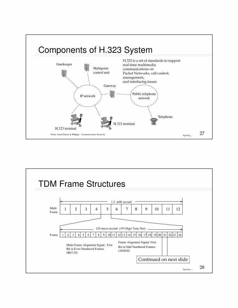
Components of H.323 System
IP networkPublic telephone
network
Gatekeeper
Gateway
H.323 terminal
H.323 terminal
Telephone
Multipoint
control unit
From: Leon-Garcia & Widjaja: Communication Networks
H.323 is a set of standards to supportreal-time multimedia communications on Packet Networks, call control, management,and interfacing issues
28Signaling ….
TDM Frame Structures
Continued on next slide
29Signaling ….
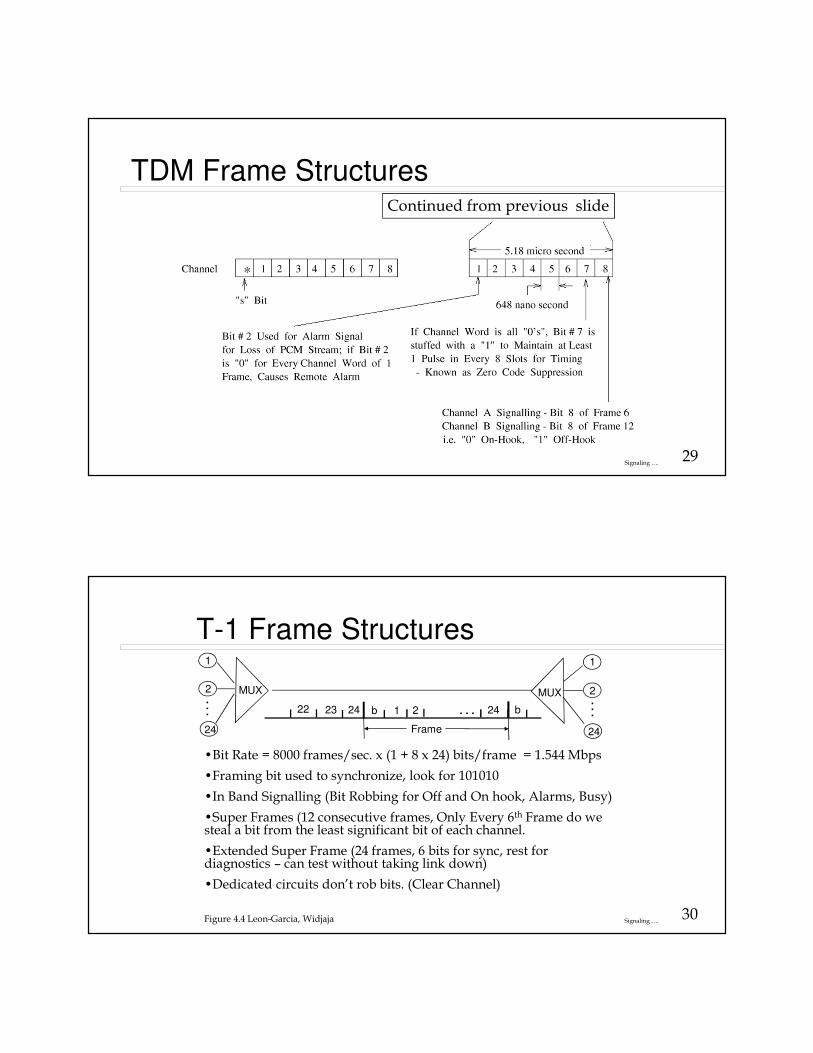
TDM Frame StructuresContinued from previous slide
30Signaling ….
T-1 Frame Structures
2
24
1 1
2
24
24 b1 2 . . .b2322
Frame
24 . . .
. . .
MUX MUX
•Bit Rate = 8000 frames/sec. x (1 + 8 x 24) bits/frame = 1.544 Mbps
•Framing bit used to synchronize, look for 101010
•In Band Signalling (Bit Robbing for Off and On hook, Alarms, Busy)
•Super Frames (12 consecutive frames, Only Every 6th Frame do we steal a bit from the least significant bit of each channel.
•Extended Super Frame (24 frames, 6 bits for sync, rest for diagnostics – can test without taking link down)
•Dedicated circuits don’t rob bits. (Clear Channel)
Figure 4.4 Leon-Garcia, Widjaja
31Signaling ….
T-Carrier Framing Cont.� Timing
� Bit Sync – recover the clock from received bit stream
� Requires minimum one’s density – can’t flatline.
� Voice coding schemes never encode a sample as all zeros
� But data could so ..– AMI – Alternate Mark Inversion - Steal a bit per byte and
set it to 1 – Zero Code Suppression (ZCS) – 56K per DS0. AMI alternates the polarity of a “1” being transmitted.
– Or use B8ZS – substitution, along with line encoding trick. Perform a deliberate AMI violation, I.e. don’t alternate on 4th and 7th bit of the substitution pattern. The pattern is 00011011. - Can transmit full 64K data –Clear Channel
32Signaling ….
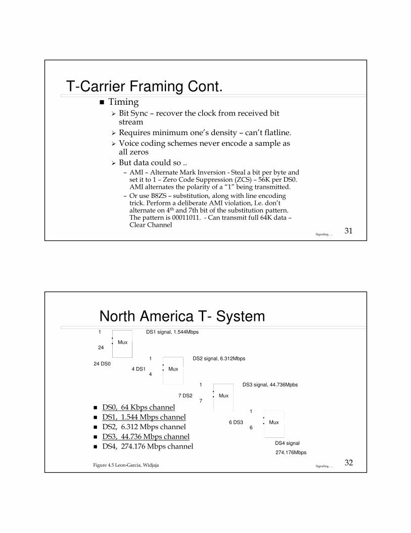
North America T- System1
24
1
4
1
7
1
6
.
.
.
.
.
.
.
.
Mux
Mux
Mux
Mux
DS1 signal, 1.544Mbps
DS2 signal, 6.312Mbps
DS3 signal, 44.736Mpbs
DS4 signal
274.176Mbps
24 DS04 DS1
7 DS2
6 DS3
� DS0, 64 Kbps channel
� DS1, 1.544 Mbps channel
� DS2, 6.312 Mbps channel
� DS3, 44.736 Mbps channel
� DS4, 274.176 Mbps channel
Figure 4.5 Leon-Garcia, Widjaja
33Signaling ….
TDM Frame Structures
�E1 System
�32 time slots
�8 bits/slot
�2.048 Mb/s
�2 time slots (128 kb/s) used for signaling
34Signaling ….
SONET(Synchronous Optical Network)
� Open standard for optical transmission and interfaces
� It defines standard optical signals, a synchronous frame structure for multiplexed digital traffic, and operations procedures
� SONET (Synchronous Optical Network) is an specification developed by Bellcore in 1985 for optical transmission networks
35Signaling ….
SONET(Synchronous Optical Network)
� ITU-T (CCITT) also adopted a set of SONET interface standards
� By the end of the 1980s, ITU-T (CCITT) adopted SONET as one of the physical layer standards for BISDN
� Framing overhead not in the cell structure
� Transport overhead distributed throughout the frame
� Frame time = 125us
36Signaling ….
SONET
� Extensive management, performance monitoring, and fault detection
� Operations, Administration, and Maintenance (OAM) functions
� Synchronous multiplexing
� Compatible with DS0, DS1, and DS3 transport mechanism as well as ATM
� Software control and access to DS0, DS1, and DS3, Add/Drop multiplexers
� Transport of advanced services
37Signaling ….
Low-speed
mapping
function
DS1
DS2
E1 STS-1
51.84 Mbps
Medium
speed
mapping
function
DS3
44.736
STS-1
High-
speed
mapping
function
E4
139.264
STS-1STS-1STS-1
STS-3cMUX
OC-n
Scrambler E/O
STS-n
ATM or POS
STS-3c
High-
speed
mapping
function
STS-1STS-1STS-1
. . .
. . .
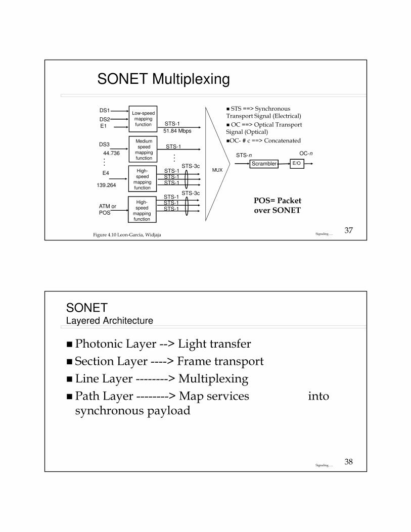
SONET Multiplexing
Figure 4.10 Leon-Garcia, Widjaja
� STS ==> Synchronous Transport Signal (Electrical)
� OC ==> Optical Transport Signal (Optical)
�OC- # c ==> Concatenated
POS= Packet over SONET
38Signaling ….
SONETLayered Architecture
� Photonic Layer --> Light transfer
� Section Layer ----> Frame transport
� Line Layer --------> Multiplexing
� Path Layer --------> Map services into synchronous payload

39Signaling ….
SONET: Physical Hierarchy
� Section: Basic building block, a single run of optical cable between transmitter/receiver
� Line: Sequence of sections connected by repeaters; line end points are muxers or switches
� Path: Sequence of lines connecting the end terminals
40Signaling ….
SONET Layered Architecture
� By Signaling between elements
� Section Terminating Equipment (STE): span of fiber between adjacent devices, e.g. regenerators – Frame Transport
� Line Terminating Equipment (LTE): span between adjacent multiplexers, encompasses multiple sections - Multiplexing
� Path Terminating Equipment (PTE): span between SONET terminals at end of network, encompasses multiple lines – Map services into payload
� By Functionality
� ADMs: dropping & inserting tributaries
� Regenerators: digital signal regeneration
� Cross-Connects: interconnecting SONET streams
41Signaling ….
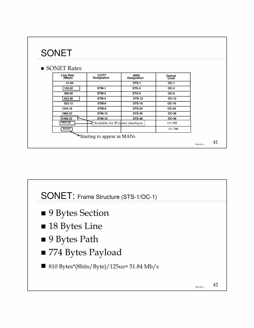
SONET
� SONET Rates
51.84
155.52
466.56
622.08
933.12
1244.16
1866.24
2488.32
STM-1
STM-3
STM-4
STM-6
STM-8
STM-12
STM-16
STS-1
STS-3
STS-9
STS-12
STS-18
STS-24
STS-36
STS-48
OC-1
OC-3
OC-9
OC-12
OC-18
OC-24
OC-36
OC-48
Line Rate (Mbps)
CCITTDesignation
ANSIDesignation
OpticalLevel
9953.28 OC-192
39,813 OC-768
Starting to appear in MANs
Available for IP router interfaces
42Signaling ….
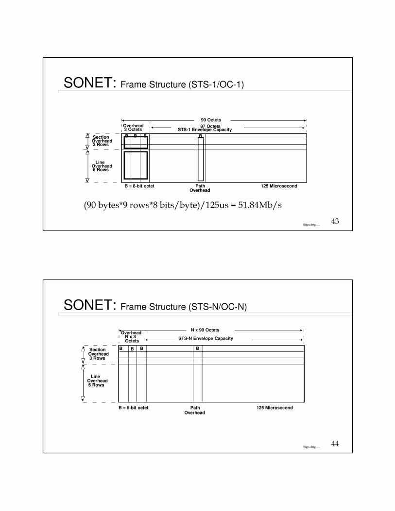
SONET: Frame Structure (STS-1/OC-1)
� 9 Bytes Section
� 18 Bytes Line
� 9 Bytes Path
� 774 Bytes Payload
� 810 Bytes*(8bits/Byte)/125us= 51.84 Mb/s
43Signaling ….
SONET: Frame Structure (STS-1/OC-1)
Overhead3 Octets
90 Octets
87 Octets
B B B BSectionOverhead3 Rows
LineOverhead6 Rows
PathOverhead
125 MicrosecondB = 8-bit octet
STS-1 Envelope Capacity
(90 bytes*9 rows*8 bits/byte)/125us = 51.84Mb/s
44Signaling ….
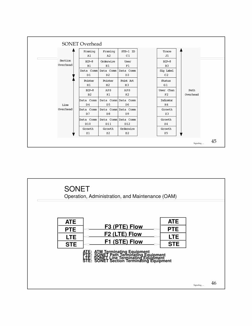
SONET: Frame Structure (STS-N/OC-N)
N x 3 Octets
OverheadN x 90 Octets
SectionOverhead3 Rows
LineOverhead6 Rows
B B B B
STS-N Envelope Capacity
PathOverhead
125 MicrosecondB = 8-bit octet
45Signaling ….
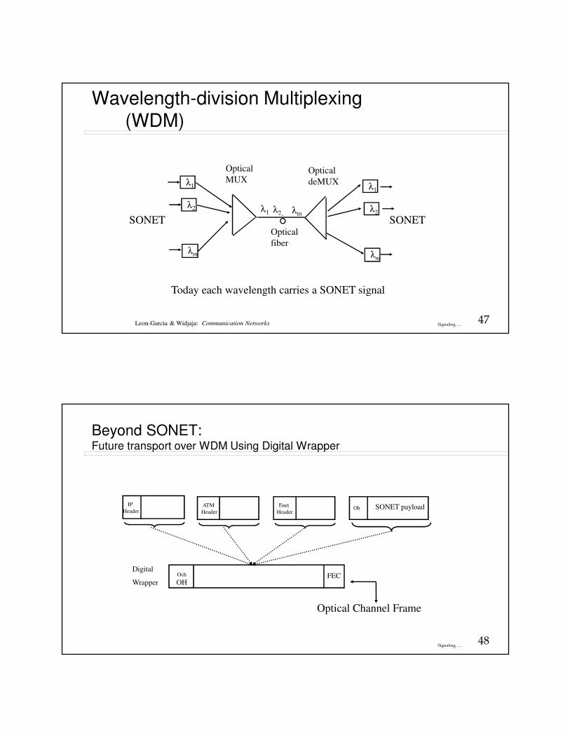
SONET Overhead
46Signaling ….
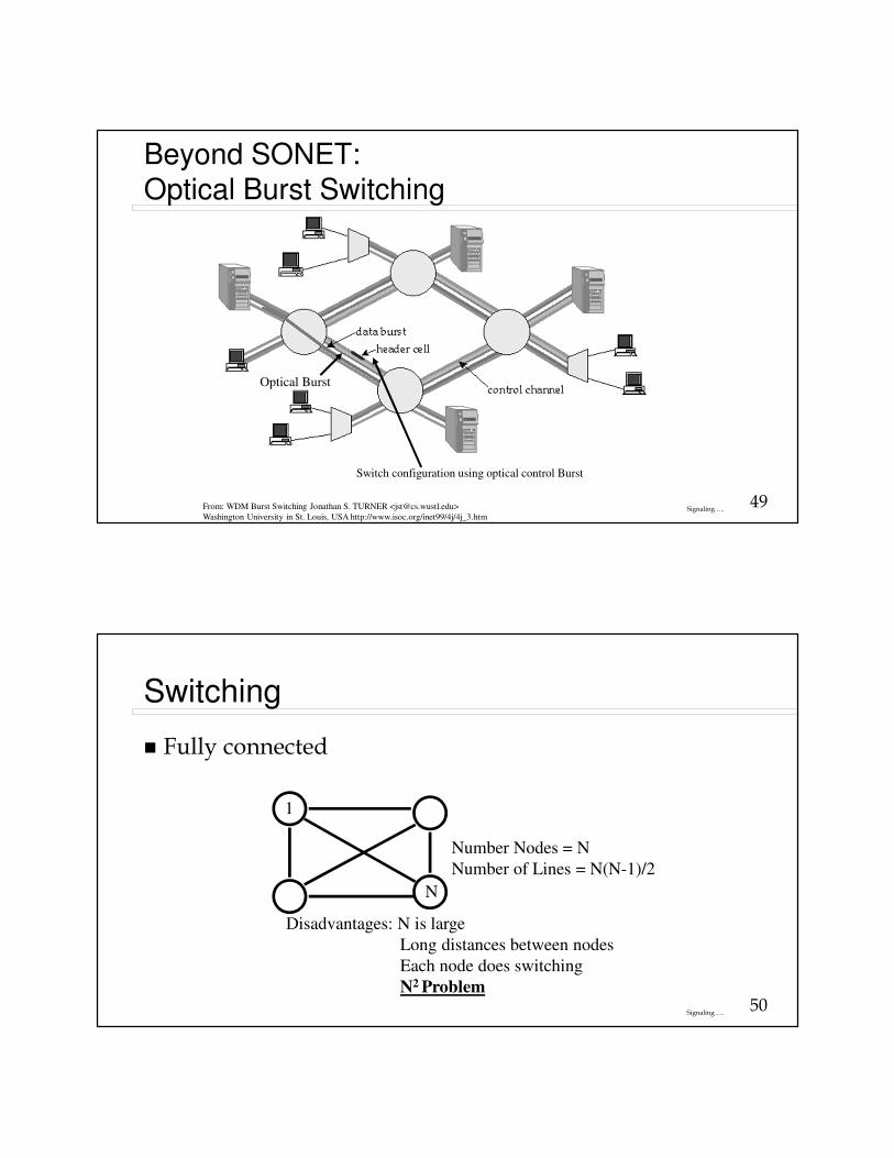
SONETOperation, Administration, and Maintenance (OAM)
ATE
PTE
LTE
STE
ATE
PTE
LTE
STE
F3 (PTE) Flow
F2 (LTE) Flow
F1 (STE) Flow
ATE: ATM Terminating EquipmentPTE: SONET Path Terminating EquipmentLTE: SONET Line Terminating EquipmentSTE: SONET Section Terminating Equipment
47Signaling ….
Wavelength-division Multiplexing (WDM)
λ1
λ2
λm
Optical
MUXλ1
λ2
λm
Optical
deMUX
λ1 λ2. λm
Optical
fiber
Leon-Garcia & Widjaja: Communication Networks
Today each wavelength carries a SONET signal
SONET SONET
48Signaling ….
Beyond SONET: Future transport over WDM Using Digital Wrapper
ATM
Header
Digital
Wrapper
Och
OHFEC
Optical Channel Frame
IP
HeaderEnet
HeaderOh SONET payload
49Signaling ….
Beyond SONET:Optical Burst Switching
From: WDM Burst Switching Jonathan S. TURNER <[email protected]>
Washington University in St. Louis, USA http://www.isoc.org/inet99/4j/4j_3.htm
Optical Burst
Switch configuration using optical control Burst
50Signaling ….
Switching
� Fully connected
Number Nodes = N
Number of Lines = N(N-1)/2
1
N
Disadvantages: N is large
Long distances between nodes
Each node does switching
N2 Problem

51Signaling ….
Switching
� Centralized switching
Connections
Control to operate
connections
Number of Lines = N
Maybe off-board
To other switches
52Signaling ….
Switch Architectures
� Crossbar
� Time division multiplex
53Signaling ….
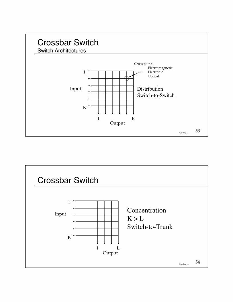
Crossbar SwitchSwitch Architectures
1
K
1 K
Distribution
Switch-to-Switch
Cross point:ElectromagneticElectronicOptical
Output
Input
54Signaling ….
Crossbar Switch
1
K
1 L
Concentration
K > L
Switch-to-Trunk
Input
Output
55Signaling ….
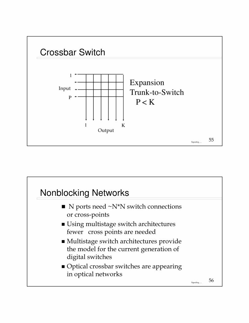
Crossbar Switch
1
P
1 K
Expansion
Trunk-to-Switch
P < K
Output
Input
56Signaling ….
Nonblocking Networks
� N ports need ~N*N switch connections or cross-points
� Using multistage switch architectures fewer cross points are needed
� Multistage switch architectures provide the model for the current generation of digital switches
� Optical crossbar switches are appearing in optical networks
57Signaling ….
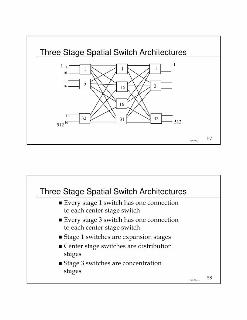
Three Stage Spatial Switch Architectures
512
1
16
1
16
1
1
1632
1
2
1
15
16
31
1
2
32512
1
58Signaling ….
Three Stage Spatial Switch Architectures
� Every stage 1 switch has one connection to each center stage switch
� Every stage 3 switch has one connection to each center stage switch
� Stage 1 switches are expansion stages
� Center stage switches are distribution stages
� Stage 3 switches are concentration stages
59Signaling ….
Three Stage Spatial Switch Architectures
�N input ports
�N output ports
�k center stage switches
�n input ports/first stage switch
�n output ports/last stage switch
�N/n first(last) stage switches
60Signaling ….
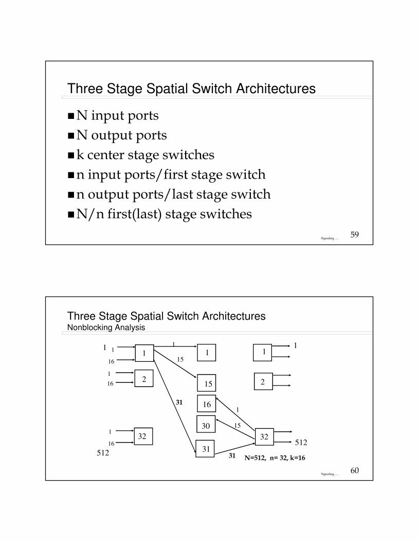
Three Stage Spatial Switch ArchitecturesNonblocking Analysis
512
1
16
1
16
1
1
1632
1
2
1
15
16
31
1
2
32512
1
30
1
15
1
15
31
31 N=512, n= 32, k=16
61Signaling ….
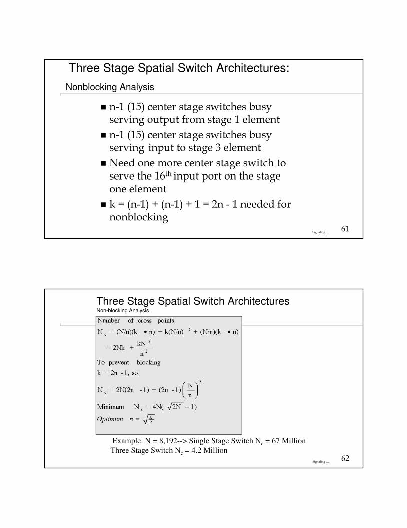
Three Stage Spatial Switch Architectures:
Nonblocking Analysis
� n-1 (15) center stage switches busy serving output from stage 1 element
� n-1 (15) center stage switches busy serving input to stage 3 element
� Need one more center stage switch to serve the 16th input port on the stage one element
� k = (n-1) + (n-1) + 1 = 2n - 1 needed for nonblocking
62Signaling ….
Three Stage Spatial Switch ArchitecturesNon-blocking Analysis
Example: N = 8,192--> Single Stage Switch Nc = 67 Million
Three Stage Switch Nc = 4.2 Million
63Signaling ….
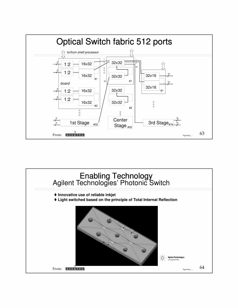
3rd Stage1st Stage
16x32
16x32
1:28
#1
1:28
32x32
32x32#1
32x16
32x16#1
16
16
16x32
16x32
1:28
#2
1:28
32x32
32x32
#2
#32
8
8Center
Stage #32#16
16
16
64
2
1 1
32
2
board
to/from shelf processor
Optical Switch fabric 512 portsOptical Switch fabric 512 ports
From:
64Signaling ….
Enabling TechnologyEnabling TechnologyAgilent Technologies’ Photonic Switch
� Innovative use of reliable inkjet
� Light switched based on the principle of Total Internal Reflection
PLC
crosspoint
waveguide
Matrix Controller
Substrate
fill hole
trench
From:

65Signaling ….
Reflecting when“bubble” is present
waveguide
Diagonal Cross Section
Transmitting when“bubble” is absent
index-matching fluid
Top-Down View
Out
In
Agilent Optical Switch ConceptAgilent Optical Switch Concept
From:
66Signaling ….
Index-matching fluid
Opticalfibers
Actuator off
(Transmitting)Silicaplanar
lightwavechip
Silicaplanar
lightwavechip
Silicon matrixcontroller chip
waveguide
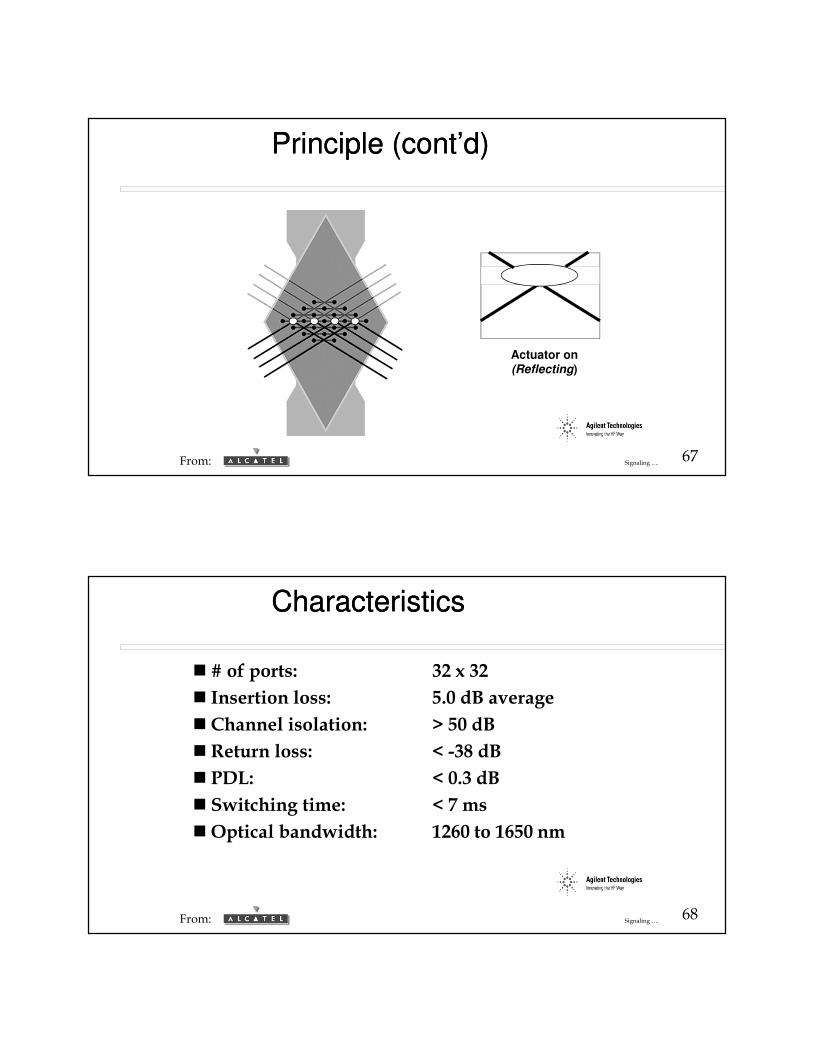
Principle (cont’d)Principle (cont’d)
From:
67Signaling ….
Actuator on(Reflecting)
Principle (cont’d)Principle (cont’d)
From:
68Signaling ….
CharacteristicsCharacteristics
� # of ports: 32 x 32
� Insertion loss: 5.0 dB average
� Channel isolation: > 50 dB
� Return loss: < -38 dB
� PDL: < 0.3 dB
� Switching time: < 7 ms
�Optical bandwidth: 1260 to 1650 nm
From:
69Signaling ….
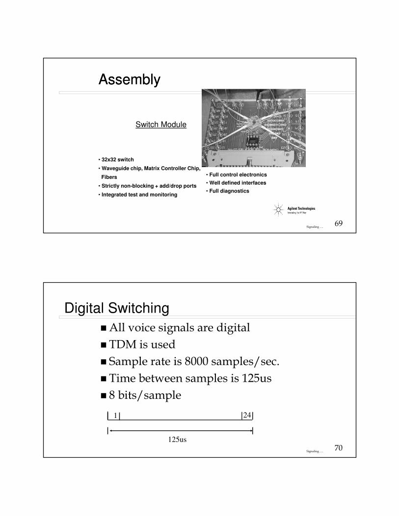
AssemblyAssembly
Switch Module
• Full control electronics
• Well defined interfaces
• Full diagnostics
• 32x32 switch
• Waveguide chip, Matrix Controller Chip,
Fibers
• Strictly non-blocking + add/drop ports
• Integrated test and monitoring
70Signaling ….
Digital Switching
� All voice signals are digital
� TDM is used
� Sample rate is 8000 samples/sec.
� Time between samples is 125us
� 8 bits/sample
1 24
125us
71Signaling ….
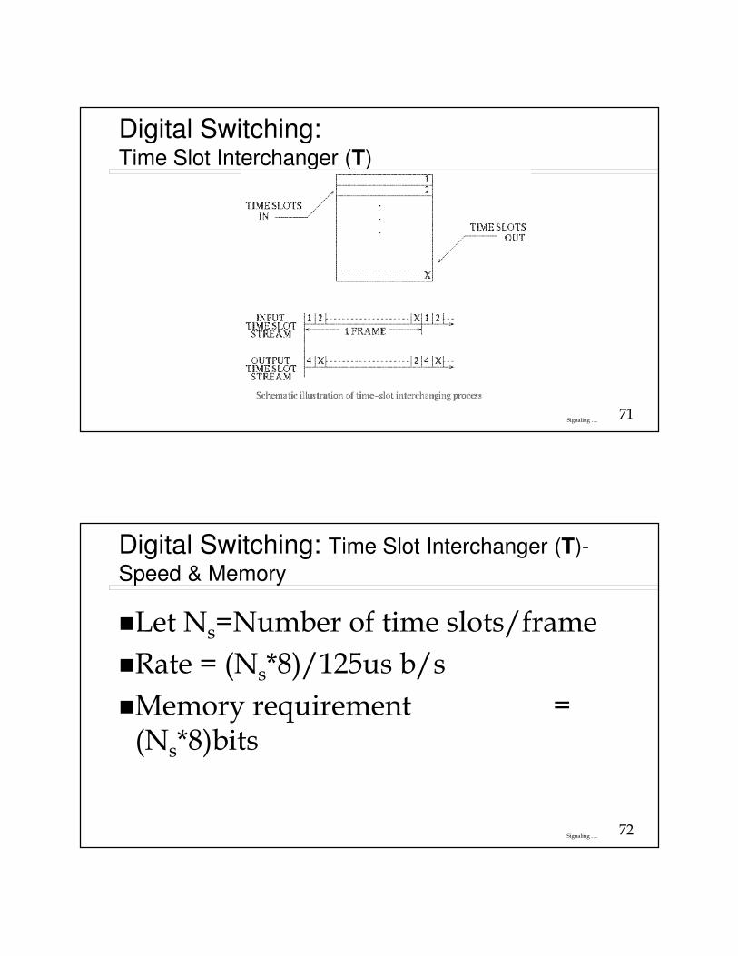
Digital Switching: Time Slot Interchanger (T)
72Signaling ….
Digital Switching: Time Slot Interchanger (T)-
Speed & Memory
�Let Ns=Number of time slots/frame
�Rate = (Ns*8)/125us b/s
�Memory requirement = (Ns*8)bits
73Signaling ….
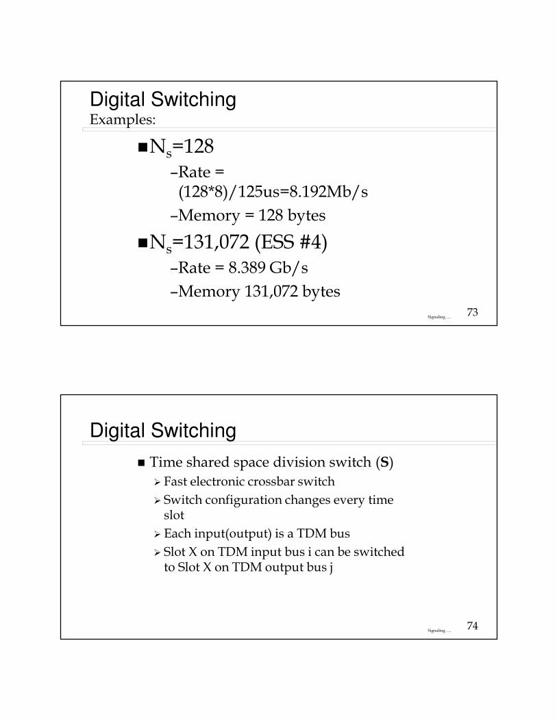
Digital SwitchingExamples:
�Ns=128–Rate = (128*8)/125us=8.192Mb/s
–Memory = 128 bytes
�Ns=131,072 (ESS #4)–Rate = 8.389 Gb/s
–Memory 131,072 bytes
74Signaling ….
Digital Switching
� Time shared space division switch (S)
� Fast electronic crossbar switch
� Switch configuration changes every time slot
� Each input(output) is a TDM bus
� Slot X on TDM input bus i can be switched to Slot X on TDM output bus j
75Signaling ….
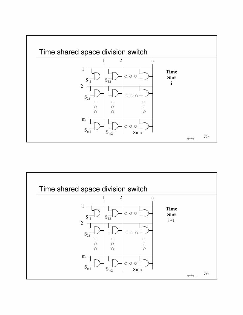
Time shared space division switch
S11
S21
Sm1 Sm2 Smn
1
1 2 n
2
m
S12
TimeSloti
76Signaling ….
Time shared space division switch
S11
S21
Sm1 Sm2 Smn
1
1 2 n
2
m
S12
TimeSloti+1
77Signaling ….
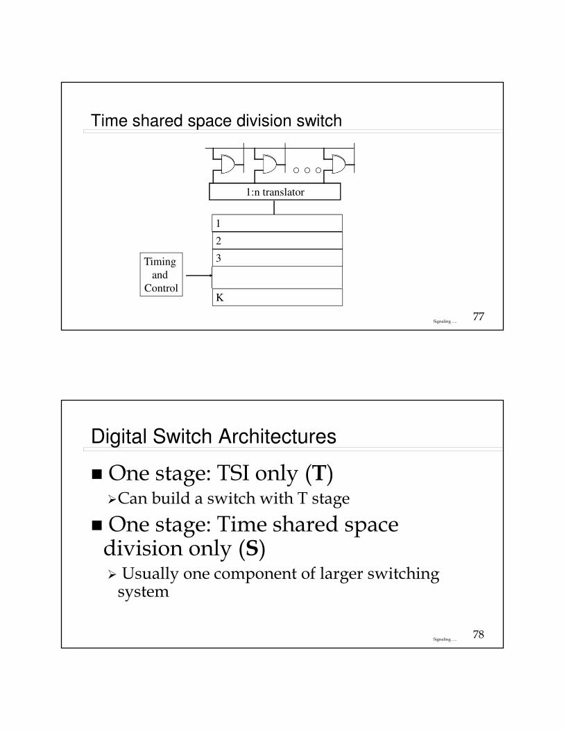
Time shared space division switch
1:n translator
1
2
3
K
Timing
and
Control
78Signaling ….
Digital Switch Architectures
� One stage: TSI only (T)�Can build a switch with T stage
� One stage: Time shared space division only (S)� Usually one component of larger switching system
79Signaling ….
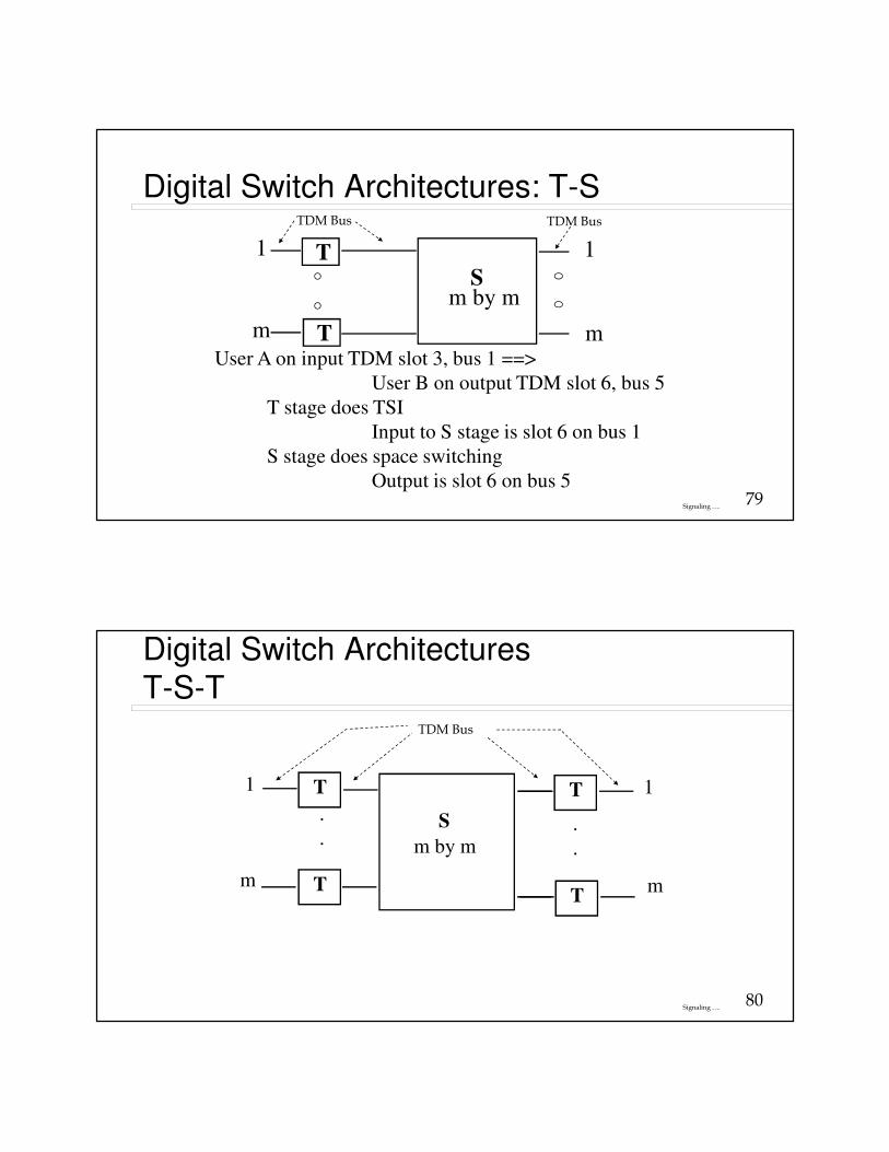
Digital Switch Architectures: T-S
T
T
S
1
m
1
m
m by m
User A on input TDM slot 3, bus 1 ==>
User B on output TDM slot 6, bus 5
T stage does TSI
Input to S stage is slot 6 on bus 1
S stage does space switching
Output is slot 6 on bus 5
TDM Bus TDM Bus
80Signaling ….
Digital Switch Architectures
T-S-T
T
T
.
.S
1
m
1
m
m by m
T
T
.
.
TDM Bus
81Signaling ….
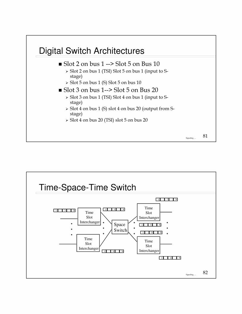
Digital Switch Architectures
� Slot 2 on bus 1 --> Slot 5 on Bus 10� Slot 2 on bus 1 (TSI) Slot 5 on bus 1 (input to S-
stage)
� Slot 5 on bus 1 (S) Slot 5 on bus 10
� Slot 3 on bus 1--> Slot 5 on Bus 20� Slot 3 on bus 1 (TSI) Slot 4 on bus 1 (input to S-
stage)
� Slot 4 on bus 1 (S) slot 4 on bus 20 (output from S-stage)
� Slot 4 on bus 20 (TSI) slot 5 on bus 20
82Signaling ….
Time-Space-Time Switch
1 3 NTime
Slot
Interchanger
Time
Slot
Interchanger
Time
Slot
Interchanger
Time
Slot
Interchanger
Space
Switch
1 5 N
1 9 N
1 5 N
1 7 N
1 9 N
1 4 N
83Signaling ….
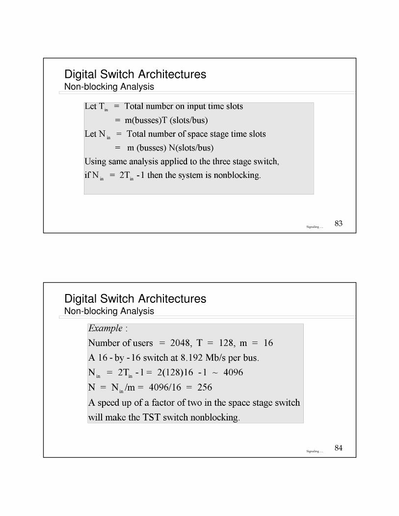
Digital Switch ArchitecturesNon-blocking Analysis
84Signaling ….
Digital Switch ArchitecturesNon-blocking Analysis
85Signaling ….
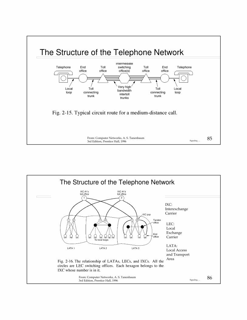
The Structure of the Telephone Network
From: Computer Networks, A. S. Tanenbaum3rd Edition, Prentice Hall, 1996
86Signaling ….
The Structure of the Telephone Network
From: Computer Networks, A. S. Tanenbaum3rd Edition, Prentice Hall, 1996
IXC:InterexchangeCarrier
LEC:Local Exchange Carrier
LATA:Local Access and Transport Area
87Signaling ….
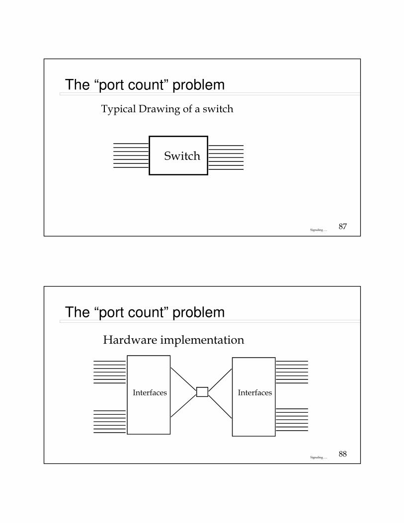
The “port count” problem
Typical Drawing of a switch
Switch
88Signaling ….
The “port count” problem
Hardware implementation
Interfaces Interfaces