signal processing engine (spe) programming environments manual€¦ · signal processing engine...
TRANSCRIPT
Signal Processing Engine (SPE)Programming Environments Manual:
A Supplement to the EREF
SPEPEMRev. 0
01/2008

Freescale™ and the Freescale logo are trademarks of Freescale Semiconductor, Inc. The Power Architecture and Power.org word marks and the Power and Power.org logos and related marks are trademarks and service marks licensed by Power.org. The PowerPC name is a trademark of IBM Corp. and is used under license. IEEE 754 is a registered trademark of the Institute of Electrical and Electronics Engineers, Inc. (IEEE). This product is not endorsed or approved by the IEEE. All other product or service names are the property of their respective owners.
© Freescale Semiconductor, Inc., 2008. Printed in the United States of America. All rights reserved.
Information in this document is provided solely to enable system and software
implementers to use Freescale Semiconductor products. There are no express or
implied copyright licenses granted hereunder to design or fabricate any integrated
circuits or integrated circuits based on the information in this document.
Freescale Semiconductor reserves the right to make changes without further notice to
any products herein. Freescale Semiconductor makes no warranty, representation or
guarantee regarding the suitability of its products for any particular purpose, nor does
Freescale Semiconductor assume any liability arising out of the application or use of
any product or circuit, and specifically disclaims any and all liability, including without
limitation consequential or incidental damages. “Typical” parameters which may be
provided in Freescale Semiconductor data sheets and/or specifications can and do
vary in different applications and actual performance may vary over time. All operating
parameters, including “Typicals” must be validated for each customer application by
customer’s technical experts. Freescale Semiconductor does not convey any license
under its patent rights nor the rights of others. Freescale Semiconductor products are
not designed, intended, or authorized for use as components in systems intended for
surgical implant into the body, or other applications intended to support or sustain life,
or for any other application in which the failure of the Freescale Semiconductor product
could create a situation where personal injury or death may occur. Should Buyer
purchase or use Freescale Semiconductor products for any such unintended or
unauthorized application, Buyer shall indemnify and hold Freescale Semiconductor
and its officers, employees, subsidiaries, affiliates, and distributors harmless against all
claims, costs, damages, and expenses, and reasonable attorney fees arising out of,
directly or indirectly, any claim of personal injury or death associated with such
unintended or unauthorized use, even if such claim alleges that Freescale
Semiconductor was negligent regarding the design or manufacture of the part.
Document Number: SPEPEMRev. 0, 01/2008
How to Reach Us:
Home Page: www.freescale.com
Web Support: http://www.freescale.com/support
USA/Europe or Locations Not Listed: Freescale Semiconductor, Inc.Technical Information Center, EL5162100 East Elliot Road Tempe, Arizona 85284 +1-800-521-6274 or+1-480-768-2130www.freescale.com/support
Europe, Middle East, and Africa:Freescale Halbleiter Deutschland GmbHTechnical Information CenterSchatzbogen 781829 Muenchen, Germany+44 1296 380 456 (English) +46 8 52200080 (English)+49 89 92103 559 (German)+33 1 69 35 48 48 (French) www.freescale.com/support
Japan: Freescale Semiconductor Japan Ltd. HeadquartersARCO Tower 15F1-8-1, Shimo-Meguro, Meguro-ku Tokyo 153-0064Japan 0120 191014 or+81 3 5437 [email protected]
Asia/Pacific: Freescale Semiconductor Hong Kong Ltd. Technical Information Center2 Dai King Street Tai Po Industrial Estate Tai Po, N.T., Hong Kong +800 2666 [email protected]
For Literature Requests Only:Freescale Semiconductor
Literature Distribution Center P.O. Box 5405Denver, Colorado 80217 +1-800 441-2447 or+1-303-675-2140Fax: +1-303-675-2150LDCForFreescaleSemiconductor
@hibbertgroup.com
Signal Processing Engine (SPE) Programming Environments Manual, Rev. 0
Freescale Semiconductor iii
ContentsParagraphNumber Title
PageNumber
Contents
About This Book
Chapter 1 Overview
1.1 Overview.......................................................................................................................... 1-11.2 Register Model................................................................................................................. 1-21.2.1 SPE Instructions........................................................................................................... 1-31.2.1.1 Embedded Vector and Scalar Floating-Point Instructions ....................................... 1-61.3 SPE and Embedded Floating-Point Exceptions and Interrupts ....................................... 1-6
Chapter 2 SPE Register Model
2.1 Overview.......................................................................................................................... 2-12.2 Register Model................................................................................................................. 2-12.2.1 General-Purpose Registers (GPRs).............................................................................. 2-32.2.2 Accumulator Register (ACC) ...................................................................................... 2-42.2.3 Signal Processing Embedded Floating-Point Status and
Control Register (SPEFSCR) .................................................................................. 2-52.2.3.1 Interrupt Vector Offset Registers (IVORs) .............................................................. 2-82.2.3.2 Exception Bit in the Exception Syndrome Register (ESR) ..................................... 2-82.2.3.3 Condition Register (CR) .......................................................................................... 2-82.2.3.4 SPE Available Bit in the Machine State Register (MSR)........................................ 2-9
Chapter 3 SPE and Embedded Floating-Point Instruction Model
3.1 Overview.......................................................................................................................... 3-13.2 SPE Instruction Set .......................................................................................................... 3-13.2.1 SPE Data Formats........................................................................................................ 3-23.2.1.1 Integer Format ......................................................................................................... 3-23.2.1.2 Fractional Format..................................................................................................... 3-23.2.2 Computational Operations ........................................................................................... 3-23.2.2.1 Data Formats and Register Usage............................................................................ 3-43.2.2.1.1 Signed Fractions .................................................................................................. 3-43.2.2.1.2 SPE Integer and Fractional Operations ............................................................... 3-43.2.2.1.3 SPE Instructions .................................................................................................. 3-53.2.3 SPE Simplified Mnemonics....................................................................................... 3-113.3 Embedded Floating-Point Instruction Set...................................................................... 3-113.3.1 Embedded Floating-Point Operations........................................................................ 3-12
Signal Processing Engine (SPE) Programming Environments Manual, Rev. 0
iv Freescale Semiconductor
ContentsParagraphNumber Title
PageNumber
3.3.1.1 Operational Modes................................................................................................. 3-123.3.1.2 Floating-Point Data Formats.................................................................................. 3-123.3.1.3 Overflow and Underflow....................................................................................... 3-133.3.1.4 IEEE Std 754™ Compliance ................................................................................. 3-143.3.1.5 Sticky Bit Handling for Exception Conditions ...................................................... 3-153.3.1.6 Implementation Options Summary........................................................................ 3-153.3.1.7 Saturation, Shift, and Bit Reverse Models............................................................. 3-153.3.1.7.1 Saturation........................................................................................................... 3-163.3.1.7.2 Shift Left............................................................................................................ 3-163.3.1.7.3 Bit Reverse ........................................................................................................ 3-163.3.2 Embedded Vector and Scalar Floating-Point Instructions ......................................... 3-163.3.3 Load/Store Instructions.............................................................................................. 3-183.3.3.1 Floating-Point Conversion Models........................................................................ 3-18
Chapter 4 SPE/Embedded Floating-Point Interrupt Model
4.1 Overview.......................................................................................................................... 4-14.2 SPE Interrupts .................................................................................................................. 4-14.2.1 Interrupt-Related Registers .......................................................................................... 4-14.2.2 Alignment Interrupt ..................................................................................................... 4-24.2.3 SPE/Embedded Floating-Point Unavailable Interrupt ................................................. 4-24.2.4 SPE Embedded Floating-Point Interrupts.................................................................... 4-34.2.4.1 Embedded Floating-Point Data Interrupt................................................................. 4-34.2.4.2 Embedded Floating-Point Round Interrupt ............................................................. 4-34.3 Interrupt Priorities............................................................................................................ 4-44.4 Exception Conditions....................................................................................................... 4-44.4.1 Floating-Point Exception Conditions .......................................................................... 4-54.4.1.1 Denormalized Values on Input................................................................................. 4-54.4.1.2 Embedded Floating-Point Overflow and Underflow............................................... 4-54.4.1.3 Embedded Floating-Point Invalid Operation/Input Errors ...................................... 4-54.4.1.4 Embedded Floating-Point Round (Inexact) ............................................................. 4-64.4.1.5 Embedded Floating-Point Divide by Zero............................................................... 4-64.4.1.6 Default Results......................................................................................................... 4-6
Chapter 5 Instruction Set
5.1 Notation ........................................................................................................................... 5-15.2 Instruction Fields ............................................................................................................. 5-25.3 Description of Instruction Operations.............................................................................. 5-2
Signal Processing Engine (SPE) Programming Environments Manual, Rev. 0
Freescale Semiconductor v
ContentsParagraphNumber Title
PageNumber
5.3.1 SPE Saturation and Bit-Reverse Models ..................................................................... 5-45.3.1.1 Saturation................................................................................................................. 5-45.3.1.2 Bit Reverse............................................................................................................... 5-55.3.2 Embedded Floating-Point Conversion Models............................................................ 5-55.3.2.1 Common Embedded Floating-Point Functions ....................................................... 5-65.3.2.1.1 32-Bit NaN or Infinity Test.................................................................................. 5-65.3.2.1.2 Signal Floating-Point Error ................................................................................. 5-65.3.2.1.3 Round a 32-Bit Value .......................................................................................... 5-65.3.2.1.4 Round a 64-Bit Value .......................................................................................... 5-75.3.2.2 Convert from Single-Precision Floating-Point to Integer Word with Saturation .... 5-75.3.2.3 Convert from Double-Precision Floating-Point to Integer Word with Saturation... 5-95.3.2.4 Convert from Double-Precision Floating-Point to Integer Double
Word with Saturation......................................................................................... 5-105.3.2.5 Convert to Single-Precision Floating-Point from Integer Word with Saturation .. 5-115.3.2.6 Convert to Double-Precision Floating-Point from Integer Word with Saturation. 5-125.3.2.7 Convert to Double-Precision Floating-Point from Integer Double
Word with Saturation......................................................................................... 5-135.3.3 Integer Saturation Models.......................................................................................... 5-145.3.4 Embedded Floating-Point Results ............................................................................. 5-145.4 Instruction Set ................................................................................................................ 5-15
Appendix A Embedded Floating-Point Results Summary
Appendix B SPE and Embedded Floating-Point Opcode Listings
B.1 Instructions (Binary) by Mnemonic.................................................................................B-1B.2 Instructions (Decimal and Hexadecimal) by Opcode ......................................................B-9B.3 Instructions by Form......................................................................................................B-16

Signal Processing Engine (SPE) Programming Environments Manual, Rev. 0
vi Freescale Semiconductor
ContentsParagraphNumber Title
PageNumber
Signal Processing Engine (SPE) Programming Environments Manual, Rev. 0
Freescale Semiconductor vii
FiguresFigureNumber Title
PageNumber
Figures
1-1 SPE Register Model ................................................................................................................ 1-21-2 Two-Element Vector Operations ............................................................................................. 1-32-1 SPE Register Model ................................................................................................................ 2-12-2 Integer, Fractional, and Floating-Point Data Formats and GPR Usage .................................. 2-22-3 32- and 64-Bit Register Elements and Bit-Numbering Conventions...................................... 2-32-4 General Purpose Registers (GPR0–GRP31) ........................................................................... 2-42-5 Accumulator (ACC)................................................................................................................ 2-42-6 Signal Processing and Embedded Floating-Point Status and Control
Register (SPEFSCR) .......................................................................................................... 2-53-1 Two-Element Vector Operations ............................................................................................. 3-33-2 Integer and Fractional Operations........................................................................................... 3-53-3 Floating-Point Data Format .................................................................................................. 3-124-1 SPE Interrupt-Related Registers ............................................................................................. 4-15-1 Instruction Description.......................................................................................................... 5-155-2 Vector Absolute Value (evabs) ............................................................................................. 5-685-3 Vector Add Immediate Word (evaddiw)............................................................................... 5-690-1 Vector Add Signed, Modulo, Integer to Accumulator Word (evaddsmiaaw)...................... 5-705-4 Vector Add Signed, Saturate, Integer to Accumulator Word (evaddssiaaw) ....................... 5-715-5 Vector Add Unsigned, Modulo, Integer to Accumulator Word (evaddumiaaw)................. 5-725-6 Vector Add Unsigned, Saturate, Integer to Accumulator Word (evaddusiaaw) .................. 5-735-7 Vector Add Word (evaddw).................................................................................................. 5-745-8 Vector AND (evand)............................................................................................................. 5-755-9 Vector AND with Complement (evandc) ............................................................................. 5-765-10 Vector Compare Equal (evcmpeq) ....................................................................................... 5-775-11 Vector Compare Greater Than Signed (evcmpgts)............................................................... 5-785-12 Vector Compare Greater Than Unsigned (evcmpgtu).......................................................... 5-795-13 Vector Compare Less Than Signed (evcmplts) .................................................................... 5-805-14 Vector Compare Less Than Unsigned (evcmpltu) ............................................................... 5-815-15 Vector Count Leading Signed Bits Word (evcntlsw)............................................................ 5-825-16 Vector Count Leading Zeros Word (evcntlzw) ..................................................................... 5-835-17 Vector Divide Word Signed (evdivws) ................................................................................. 5-845-18 Vector Divide Word Unsigned (evdivwu) ............................................................................ 5-855-19 Vector Equivalent (eveqv) .................................................................................................... 5-865-20 Vector Extend Sign Byte (evextsb)....................................................................................... 5-875-21 Vector Extend Sign Half Word (evextsh) ............................................................................. 5-885-22 evldd Results in Big- and Little-Endian Modes ................................................................. 5-1125-23 evlddx Results in Big- and Little-Endian Modes ............................................................... 5-1135-24 evldh Results in Big- and Little-Endian Modes ................................................................. 5-1145-25 evldhx Results in Big- and Little-Endian Modes ............................................................... 5-1155-26 evldw Results in Big- and Little-Endian Modes................................................................. 5-1165-27 evldwx Results in Big- and Little-Endian Modes............................................................... 5-117
Signal Processing Engine (SPE) Programming Environments Manual, Rev. 0
viii Freescale Semiconductor
FiguresFigureNumber Title
PageNumber
5-28 evlhhesplat Results in Big- and Little-Endian Modes ....................................................... 5-1185-29 evlhhesplatx Results in Big- and Little-Endian Modes ..................................................... 5-1195-30 evlhhossplat Results in Big- and Little-Endian Modes...................................................... 5-1205-31 evlhhossplatx Results in Big- and Little-Endian Modes.................................................... 5-1215-32 evlhhousplat Results in Big- and Little-Endian Modes ..................................................... 5-1225-33 evlhhousplatx Results in Big- and Little-Endian Modes ................................................... 5-1235-34 evlwhe Results in Big- and Little-Endian Modes ............................................................... 5-1245-35 evlwhex Results in Big- and Little-Endian Modes ............................................................. 5-1255-36 evlwhos Results in Big- and Little-Endian Modes ............................................................. 5-1265-37 evlwhosx Results in Big- and Little-Endian Modes ........................................................... 5-1275-38 evlwhou Results in Big- and Little-Endian Modes ............................................................ 5-1285-39 evlwhoux Results in Big- and Little-Endian Modes .......................................................... 5-1295-40 evlwhsplat Results in Big- and Little-Endian Modes ........................................................ 5-1305-41 evlwhsplatx Results in Big- and Little-Endian Modes ...................................................... 5-1315-42 evlwwsplat Results in Big- and Little-Endian Modes........................................................ 5-1325-43 evlwwsplatx Results in Big- and Little-Endian Modes...................................................... 5-1335-44 High Order Element Merging (evmergehi)........................................................................ 5-1345-45 High Order Element Merging (evmergehilo)..................................................................... 5-1355-46 Low Order Element Merging (evmergelo)......................................................................... 5-1365-47 Low Order Element Merging (evmergelohi) ..................................................................... 5-1375-48 evmhegsmfaa (Even Form)................................................................................................ 5-1385-49 evmhegsmfan (Even Form)................................................................................................ 5-1395-50 evmhegsmiaa (Even Form) ................................................................................................ 5-1405-51 evmhegsmian (Even Form)................................................................................................ 5-1415-52 evmhegumiaa (Even Form) ............................................................................................... 5-1425-53 evmhegumian (Even Form) ............................................................................................... 5-1435-54 Even Multiply of Two Signed Modulo Fractional
Elements (to Accumulator) (evmhesmf) ....................................................................... 5-1445-55 Even Form of Vector Half-Word Multiply (evmhesmfaaw) .............................................. 5-1455-56 Even Form of Vector Half-Word Multiply (evmhesmfanw).............................................. 5-1465-57 Even Form for Vector Multiply (to Accumulator) (evmhesmi) ......................................... 5-1475-58 Even Form of Vector Half-Word Multiply (evmhesmiaaw) .............................................. 5-1485-59 Even Form of Vector Half-Word Multiply (evmhesmianw) .............................................. 5-1495-60 Even Multiply of Two Signed Saturate Fractional
Elements (to Accumulator) (evmhessf) ........................................................................ 5-1505-61 Even Form of Vector Half-Word Multiply (evmhessfaaw)................................................ 5-1515-62 Even Form of Vector Half-Word Multiply (evmhessfanw) ............................................... 5-1525-63 Even Form of Vector Half-Word Multiply (evmhessiaaw) ................................................ 5-1535-64 Even Form of Vector Half-Word Multiply (evmhessianw)................................................ 5-1545-65 Vector Multiply Half Words, Even, Unsigned, Modulo,
Integer (to Accumulator) (evmheumi) .......................................................................... 5-155
Signal Processing Engine (SPE) Programming Environments Manual, Rev. 0
Freescale Semiconductor ix
FiguresFigureNumber Title
PageNumber
5-66 Even Form of Vector Half-Word Multiply (evmheumiaaw) ............................................. 5-1565-67 Even Form of Vector Half-Word Multiply (evmheumianw) ............................................. 5-1575-68 Even Form of Vector Half-Word Multiply (evmheusiaaw) ............................................... 5-1585-69 Even Form of Vector Half-Word Multiply (evmheusianw) ............................................... 5-1595-70 evmhogsmfaa (Odd Form) ................................................................................................. 5-1605-71 evmhogsmfan (Odd Form)................................................................................................. 5-1615-72 evmhogsmiaa (Odd Form) ................................................................................................. 5-1625-73 evmhogsmian (Odd Form) ................................................................................................. 5-1635-74 evmhogumiaa (Odd Form) ................................................................................................ 5-1645-75 evmhogumian (Odd Form) ................................................................................................ 5-1655-76 Vector Multiply Half Words, Odd, Signed, Modulo,
Fractional (to Accumulator) (evmhosmf)...................................................................... 5-1665-77 Odd Form of Vector Half-Word Multiply (evmhosmfaaw) ............................................... 5-1675-78 Odd Form of Vector Half-Word Multiply (evmhosmfanw)............................................... 5-1685-79 Vector Multiply Half Words, Odd, Signed, Modulo,
Integer (to Accumulator) (evmhosmi) ........................................................................... 5-1695-80 Odd Form of Vector Half-Word Multiply (evmhosmiaaw) ............................................... 5-1705-81 Odd Form of Vector Half-Word Multiply (evmhosmianw) ............................................... 5-1715-82 Vector Multiply Half Words, Odd, Signed, Saturate,
Fractional (to Accumulator) (evmhossf)........................................................................ 5-1735-83 Odd Form of Vector Half-Word Multiply (evmhossfaaw)................................................. 5-1745-84 Odd Form of Vector Half-Word Multiply (evmhossfanw)................................................. 5-1755-85 Odd Form of Vector Half-Word Multiply (evmhossiaaw) ................................................. 5-1765-86 Odd Form of Vector Half-Word Multiply (evmhossianw)................................................. 5-1775-87 Vector Multiply Half Words, Odd, Unsigned, Modulo,
Integer (to Accumulator) (evmhoumi) .......................................................................... 5-1785-88 Odd Form of Vector Half-Word Multiply (evmhoumiaaw)............................................... 5-1795-89 Odd Form of Vector Half-Word Multiply (evmhoumianw) .............................................. 5-1805-90 Odd Form of Vector Half-Word Multiply (evmhousiaaw) ................................................ 5-1815-91 Odd Form of Vector Half-Word Multiply (evmhousianw) ................................................ 5-1825-92 Initialize Accumulator (evmra) .......................................................................................... 5-1835-93 Vector Multiply Word High Signed, Modulo,
Fractional (to Accumulator) (evmwhsmf) ..................................................................... 5-1845-94 Vector Multiply Word High Signed, Modulo,
Integer (to Accumulator) (evmwhsm) ........................................................................... 5-1855-95 Vector Multiply Word High Signed, Saturate,
Fractional (to Accumulator) (evmwhssf)....................................................................... 5-1875-96 Vector Multiply Word High Unsigned, Modulo,
Integer (to Accumulator) (evmwhumi) ......................................................................... 5-1885-97 Vector Multiply Word Low Signed, Modulo, Integer and
Accumulate in Words (evmwlsmiaaw) ......................................................................... 5-189
Signal Processing Engine (SPE) Programming Environments Manual, Rev. 0
x Freescale Semiconductor
FiguresFigureNumber Title
PageNumber
5-98 Vector Multiply Word Low Signed, Modulo, Integer andAccumulate Negative in Words (evmwlsmianw).......................................................... 5-190
5-99 Vector Multiply Word Low Signed, Saturate, Integer andAccumulate in Words (evmwlssiaaw) ........................................................................... 5-192
5-100 Vector Multiply Word Low Signed, Saturate, Integer andAccumulate Negative in Words (evmwlssianw ............................................................. 5-193
5-101 Vector Multiply Word Low Unsigned, Modulo, Integer (evmwlumi) ............................... 5-1945-102 Vector Multiply Word Low Unsigned, Modulo, Integer and
Accumulate in Words (evmwlumiaaw)......................................................................... 5-1955-103 Vector Multiply Word Low Unsigned, Modulo, Integer and
Accumulate Negative in Words (evmwlumianw) ......................................................... 5-1965-104 Vector Multiply Word Low Unsigned, Saturate, Integer and
Accumulate in Words (evmwlusiaaw)........................................................................... 5-1975-105 Vector Multiply Word Low Unsigned, Saturate, Integer and
Accumulate Negative in Words (evmwlusianw) ........................................................... 5-1985-106 Vector Multiply Word Signed, Modulo,
Fractional (to Accumulator) (evmwsmf) ....................................................................... 5-1995-107 Vector Multiply Word Signed, Modulo, Fractional and
Accumulate (evmwsmfaa)............................................................................................. 5-2005-108 Vector Multiply Word Signed, Modulo, Fractional and
Accumulate Negative (evmwsmfan) ............................................................................. 5-2015-109 Vector Multiply Word Signed, Modulo,
Integer (to Accumulator) (evmwsmi) ............................................................................ 5-2025-110 Vector Multiply Word Signed, Modulo, Integer and
Accumulate (evmwsmiaa) ............................................................................................. 5-2035-111 Vector Multiply Word Signed, Modulo, Integer and
Accumulate Negative (evmwsmian) ............................................................................. 5-2045-112 Vector Multiply Word Signed, Saturate,
Fractional (to Accumulator) (evmwssf) ......................................................................... 5-2055-113 Vector Multiply Word Signed, Saturate, Fractional, and
Accumulate (evmwssfaa) .............................................................................................. 5-2065-114 Vector Multiply Word Signed, Saturate, Fractional and
Accumulate Negative (evmwssfan)............................................................................... 5-2075-115 Vector Multiply Word Unsigned, Modulo,
Integer (to Accumulator) (evmwumi)............................................................................ 5-2085-116 Vector Multiply Word Unsigned, Modulo, Integer and
Accumulate (evmwumiaa) ............................................................................................ 5-2095-117 Vector Multiply Word Unsigned, Modulo, Integer and
Accumulate Negative (evmwumian)............................................................................. 5-2105-118 Vector NAND (evnand)...................................................................................................... 5-2115-119 Vector Negate (evneg) ........................................................................................................ 5-212
Signal Processing Engine (SPE) Programming Environments Manual, Rev. 0
Freescale Semiconductor xi
FiguresFigureNumber Title
PageNumber
5-120 Vector NOR (evnor) ........................................................................................................... 5-2135-121 Vector OR (evor) ................................................................................................................ 5-2145-122 Vector OR with Complement (evorc) ................................................................................. 5-2155-123 Vector Rotate Left Word (evrlw) ........................................................................................ 5-2165-124 Vector Rotate Left Word Immediate (evrlwi) ..................................................................... 5-2175-125 Vector Round Word (evrndw) ............................................................................................ 5-2185-126 Vector Select (evsel)............................................................................................................ 5-2195-127 Vector Shift Left Word (evslw) ........................................................................................... 5-2205-128 Vector Shift Left Word Immediate (evslwi)........................................................................ 5-2215-129 Vector Splat Fractional Immediate (evsplatfi).................................................................... 5-2225-130 evsplati Sign Extend........................................................................................................... 5-2235-131 Vector Shift Right Word Immediate Signed (evsrwis) ....................................................... 5-2245-132 Vector Shift Right Word Immediate Unsigned (evsrwiu) .................................................. 5-2255-133 Vector Shift Right Word Signed (evsrws) .......................................................................... 5-2265-134 Vector Shift Right Word Unsigned (evsrwu)...................................................................... 5-2275-135 evstdd Results in Big- and Little-Endian Modes................................................................ 5-2285-136 evstddx Results in Big- and Little-Endian Modes.............................................................. 5-2295-137 evstdh Results in Big- and Little-Endian Modes................................................................ 5-2305-138 evstdhx Results in Big- and Little-Endian Modes.............................................................. 5-2315-139 evstdw Results in Big- and Little-Endian Modes ............................................................... 5-2325-140 evstdwx Results in Big- and Little-Endian Modes ............................................................. 5-2335-141 evstwhe Results in Big- and Little-Endian Modes ............................................................. 5-2345-142 evstwhex Results in Big- and Little-Endian Modes ........................................................... 5-2355-143 evstwho Results in Big- and Little-Endian Modes ............................................................. 5-2365-144 evstwhox Results in Big- and Little-Endian Modes ........................................................... 5-2375-145 evstwwe Results in Big- and Little-Endian Modes ............................................................ 5-2385-146 evstwwex Results in Big- and Little-Endian Modes .......................................................... 5-2395-147 evstwwo Results in Big- and Little-Endian Modes ............................................................ 5-2405-148 evstwwox Results in Big- and Little-Endian Modes .......................................................... 5-2415-149 Vector Subtract Signed, Modulo, Integer to
Accumulator Word (evsubfsmiaaw).............................................................................. 5-2425-150 Vector Subtract Signed, Saturate, Integer to
Accumulator Word (evsubfssiaaw) ............................................................................... 5-2435-151 Vector Subtract Unsigned, Modulo, Integer to
Accumulator Word (evsubfumiaaw) ............................................................................. 5-2445-152 Vector Subtract Unsigned, Saturate, Integer to
Accumulator Word (evsubfusiaaw)............................................................................... 5-2455-153 Vector Subtract from Word (evsubfw)................................................................................ 5-2465-154 Vector Subtract Immediate from Word (evsubifw) ............................................................ 5-2475-155 Vector XOR (evxor)............................................................................................................ 5-248

Signal Processing Engine (SPE) Programming Environments Manual, Rev. 0
xii Freescale Semiconductor
FiguresFigureNumber Title
PageNumber
Signal Processing Engine (SPE) Programming Environments Manual, Rev. 0
Freescale Semiconductor xiii
TablesTableNumber Title
PageNumber
Tables
1-1 SPE Vector Multiply Instruction Mnemonic Structure ........................................................... 1-11-2 Mnemonic Extensions for Multiply Accumulate Instructions ................................................ 1-41-3 SPE Vector Multiply Instruction Mnemonic Structure ........................................................... 1-51-4 Mnemonic Extensions for Multiply-Accumulate Instructions................................................ 1-52-1 SPEFSCR Field Descriptions ................................................................................................. 2-52-2 SPE Instructions that Use the CR ........................................................................................... 2-82-3 Embedded Floating-Point Instructions that Use the CR ......................................................... 2-83-1 Mnemonic Extensions for Multiply Accumulate Instructions ................................................ 3-33-2 SPE Vector Multiply Instruction Mnemonic Structure ........................................................... 3-53-3 Mnemonic Extensions for Multiply-Accumulate Instructions................................................ 3-53-4 SPE Instructions ...................................................................................................................... 3-63-5 SPE Simplified Mnemonics .................................................................................................. 3-113-6 Vector and Scalar Floating-Point Instructions ...................................................................... 3-174-1 SPE/SPE Embedded Floating-Point Interrupt and Exception Types ...................................... 4-15-1 Notation Conventions ............................................................................................................. 5-15-2 Instruction Field Descriptions ................................................................................................. 5-25-3 RTL Notation .......................................................................................................................... 5-25-4 Operator Precedence ............................................................................................................... 5-45-5 Conversion Models ................................................................................................................. 5-55-6 Data Samples and Sizes ........................................................................................................ 5-16A-1 Embedded Floating-Point Results Summary—Add, Sub, Mul, Div ..................................... A-1A-2 Embedded Floating-Point Results Summary—Single Convert from Double ....................... A-5A-3 Embedded Floating-Point Results Summary—Double Convert from Single ....................... A-5A-4 Embedded Floating-Point Results Summary—Convert to Unsigned.................................... A-6A-5 Embedded Floating-Point Results Summary—Convert to Signed ........................................ A-6A-6 Results Summary—Convert from Unsigned ......................................................................... A-6A-7 Embedded Floating-Point Results Summary—Convert from Signed ................................... A-7A-8 Embedded Floating-Point Results Summary—*abs, *nabs, *neg......................................... A-7B-1 Instructions (Binary) by Mnemonic........................................................................................B-1B-2 Instructions (Decimal and Hexadecimal) by Opcode .............................................................B-9B-3 Instructions (Binary) by Form...............................................................................................B-16

Signal Processing Engine (SPE) Programming Environments Manual, Rev. 0
xiv Freescale Semiconductor
TablesTableNumber Title
PageNumber
Signal Processing Engine (SPE) Programming Environments Manual, Rev. 0
Freescale Semiconductor xv
About This BookThe primary objective of this manual is to help programmers provide software compatible with processors that implement the signal processing engine (SPE) and embedded floating-point instruction sets.
To locate any published errata or updates for this document, refer to the web at http://www.freescale.com.
This book is used as a reference guide for assembler programmers. It uses a standardized format instruction to describe each instruction, showing syntax, instruction format, register translation language (RTL) code that describes how the instruction works, and a listing of which, if any, registers are affected. At the bottom of each instruction entry is a figure that shows the operations on elements within source operands and where the results of those operations are placed in the destination operand.
The SPE Programming Interface Manual (SPEPIM) is a reference guide for high-level programmers. The VLEPIM describes how programmers can access SPE functionality from programming languages such as C and C++. It defines a programming model for use with the SPE instruction set. Processors that implement the Power ISA™ (instruction set architecture) use the SPE instruction set as an extension to the base and embedded categories of the Power ISA.
Because it is important to distinguish among the categories of the Power ISA to ensure compatibility across multiple platforms, those distinctions are shown clearly throughout this book. This document stays consistent with the Power ISA in referring to three levels, or programming environments, which are as follows:
• User instruction set architecture (UISA)—The UISA defines the level of the architecture to which user-level software should conform. The UISA defines the base user-level instruction set, user-level registers, data types, memory conventions, and the memory and programming models seen by application programmers.
• Virtual environment architecture (VEA)—The VEA, which is the smallest component of the architecture, defines additional user-level functionality that falls outside typical user-level software requirements. The VEA describes the memory model for an environment in which multiple processors or other devices can access external memory and defines aspects of the cache model and cache control instructions from a user-level perspective. VEA resources are particularly useful for optimizing memory accesses and for managing resources in an environment in which other processors and other devices can access external memory.
Implementations that conform to the VEA also conform to the UISA but may not necessarily adhere to the OEA.
• Operating environment architecture (OEA)—The OEA defines supervisor-level resources typically required by an operating system. It defines the memory management model, supervisor-level registers, and the exception model.
Implementations that conform to the OEA also conform to the UISA and VEA.

Signal Processing Engine (SPE) Programming Environments Manual, Rev. 0
xvi Freescale Semiconductor
Most of the discussions on the SPE are at the UISA level. For ease in reference, this book and the processor reference manuals have arranged the architecture information into topics that build on one another, beginning with a description and complete summary of registers and instructions (for all three environments) and progressing to more specialized topics such as the cache, exception, and memory management models. As such, chapters may include information from multiple levels of the architecture, but when discussing OEA and VEA, the level is noted in the text.
It is beyond the scope of this manual to describe individual devices that implement SPE. It must be kept in mind that each processor that implements the Power ISA is unique in its implementation.
The information in this book is subject to change without notice, as described in the disclaimers on the title page of this book. As with any technical documentation, it is the readers’ responsibility to be sure they are using the most recent version of the documentation. For more information, contact your sales representative or visit our web site at http://www.freescale.com.
AudienceThis manual is intended for system software and hardware developers, and for application programmers who want to develop products using the SPE. It is assumed that the reader understands operating systems, microprocessor system design, the basic principles of RISC processing, and details of the Power ISA.
This book describes how SPE interacts with the other components of the architecture.
OrganizationFollowing is a summary and a brief description of the major sections of this manual:
• Chapter 1, “Overview,” is useful for those who want a general understanding of the features and functions of the SPE. This chapter provides an overview of how the VLE defines the register set, operand conventions, addressing modes, instruction set, and interrupt model.
• Chapter 2, “SPE Register Model,” lists the register resources defined by the SPE and embedded floating-point ISAs. It also lists base category resources that are accessed by SPE and embedded floating-point instructions.
• Chapter 3, “SPE and Embedded Floating-Point Instruction Model,” describes the SPE and embedded floating-point instruction set, including operand conventions, addressing modes, and instruction syntax. It also provides a brief description of instructions grouped by category.
• Chapter 5, “Instruction Set,” functions as a handbook for the SPE and embedded floating-point instruction set. Instructions are sorted by mnemonic. Each instruction description includes the instruction formats and figures where it helps in understanding what the instruction does.
• Appendix A, “Embedded Floating-Point Results Summary,” summarizes the results of various types of embedded floating-point operations on various combinations of input operands.
• Appendix B, “SPE and Embedded Floating-Point Opcode Listings,” lists all SPE and embedded-floating point instructions, grouped according to mnemonic and opcode.
This manual also includes an index.
Signal Processing Engine (SPE) Programming Environments Manual, Rev. 0
Freescale Semiconductor xvii
Suggested ReadingThis section lists additional reading that provides background for the information in this manual as well as general information about the VLE and the Power ISA.
General Information
The following documentation provides useful information about the Power Architecture™ technology and computer architecture in general:
• Computer Architecture: A Quantitative Approach, Third Edition, by John L. Hennessy and David A. Patterson.
• Computer Organization and Design: The Hardware/Software Interface, Third Edition, David A. Patterson and John L. Hennessy.
Related Documentation
Freescale documentation is available from the sources listed on the back of the title page; the document order numbers, when applicable, are included in parentheses for ease in ordering:
• EREF: A Programmer's Reference Manual for Freescale Embedded Processors (EREFRM). Describes the programming, memory management, cache, and interrupt models defined by the Power ISA for embedded environment processors.
• Power ISA™. The latest version of the Power ISA can be downloaded from the website www.power.org.
• Variable-Length Encoding (VLE) Extension Programming Interface Manual (VLEPIM). Provides the VLE-specific extensions to the e500 application binary interface.
• e500 Application Binary Interface User's Guide (E500ABIUG). Establishes a standard binary interface for application programs on systems that implement the interfaces defined in the System V Interface Definition, Issue 3. This includes systems that have implemented UNIX System V Release 4.
• Reference manuals. The following reference manuals provide details information about processor cores and integrated devices:
— Core reference manuals—These books describe the features and behavior of individual microprocessor cores and provide specific information about how functionality described in the EREF is implemented by a particular core. They also describe implementation-specific features and microarchitectural details, such as instruction timing and cache hardware details, that lie outside the architecture specification.
— Integrated device reference manuals—These manuals describe the features and behavior of integrated devices that implement a Power ISA processor core. It is important to understand that some features defined for a core may not be supported on all devices that implement that core.
Also, some features are defined in a general way at the core level and have meaning only in the context of how the core is implemented. For example, any implementation-specific behavior of register fields can be described only in the reference manual for the integrated device.
Signal Processing Engine (SPE) Programming Environments Manual, Rev. 0
xviii Freescale Semiconductor
Each of these documents include the following two chapters that are pertinent to the core:
– A core overview. This chapter provides a general overview of how the core works and indicates which of a core’s features are implemented on the integrated device.
– A register summary chapter. This chapter gives the most specific information about how register fields can be interpreted in the context of the implementation.
These reference manuals also describe how the core interacts with other blocks on the integrated device, especially regarding topics such as reset, interrupt controllers, memory and cache management, debug, and global utilities.
• Addenda/errata to reference manuals—Errata documents are provided to address errors in published documents.
Because some processors have follow-on parts, often an addendum is provided that describes the additional features and functionality changes. These addenda, which may also contain errata, are intended for use with the corresponding reference manuals.
Always check the Freescale website for updates to reference manuals.
• Hardware specifications—Hardware specifications provide specific data regarding bus timing; signal behavior; AC, DC, and thermal characteristics; and other design considerations.
• Product brief—Each integrated device has a product brief that provides an overview of its features. This document is roughly the equivalent to the overview (Chapter 1) of the device’s reference manual.
• Application notes—These short documents address specific design issues useful to programmers and engineers working with Freescale processors.
Additional literature is published as new processors become available. For current documentation, refer to http://www.freescale.com.
ConventionsThis document uses the following notational conventions:
cleared/set When a bit takes the value zero, it is said to be cleared; when it takes a value of one, it is said to be set.
mnemonics Instruction mnemonics are shown in lowercase bold
italics Italics indicate variable command parameters, for example, bcctrx
Book titles in text are set in italics
0x0 Prefix to denote hexadecimal number
0b0 Prefix to denote binary number
rA, rB Instruction syntax used to identify a source general-purpose register (GPR)
rD Instruction syntax used to identify a destination GPR
frA, frB, frC Instruction syntax used to identify a source floating-point register (FPR)
frD Instruction syntax used to identify a destination FPR
REG[FIELD] Abbreviations for registers are shown in uppercase text. Specific bits, fields, or ranges appear in brackets.
Signal Processing Engine (SPE) Programming Environments Manual, Rev. 0
Freescale Semiconductor xix
x In some contexts, such as signal encodings, an unitalicized x indicates a don’t care.
x An italicized x indicates an alphanumeric variable
n An italicized n indicates a numeric variable
¬ NOT logical operator
& AND logical operator
| OR logical operator
Indicates reserved bits or bit fields in a register. Although these bits may be written to as ones or zeros, they are always read as zeros.
Additional conventions used with instruction encodings are described in Section 5.1, “Notation.”
Acronyms and AbbreviationsTable i contains acronyms and abbreviations that are used in this document. Note that the meanings for some acronyms (such as XER) are historical, and the words for which an acronym stands may not be intuitively obvious.
Table i. Acronyms and Abbreviated Terms
Term Meaning
CR Condition register
CTR Count register
DEC Decrementer register
EA Effective address
EREF A Programmer's Reference Manual for Freescale Embedded Processors (Including the e200 and e500 Families)
GPR General-purpose register
IEEE Institute of Electrical and Electronics Engineers
IU Integer unit
LR Link register
LRU Least recently used
LSB Least significant byte
lsb Least significant bit
LSU Load/store unit
MMU Memory management unit
MSB Most significant byte
msb Most significant bit
MSR Machine state register
NaN Not a number
No-op No operation
OEA Operating environment architecture
0 0 0 0

Signal Processing Engine (SPE) Programming Environments Manual, Rev. 0
xx Freescale Semiconductor
Terminology ConventionsTable ii lists certain terms used in this manual that differ from the architecture terminology conventions.
PMCn Performance monitor counter register
PVR Processor version register
RISC Reduced instruction set computing
RTL Register transfer language
SIMM Signed immediate value
SPR Special-purpose register
SRR0 Machine status save/restore register 0
SRR1 Machine status save/restore register 1
TB Time base facility
TBL Time base lower register
TBU Time base upper register
TLB Translation lookaside buffer
UIMM Unsigned immediate value
UISA User instruction set architecture
VA Virtual address
VEA Virtual environment architecture
VLEPEM Variable-Length Encoding (VLE) Programming Environments Manual
VLEPIM Variable-Length Encoding (VLE) Extension Programming Interface Manual (VLEPIM)
XER Register used for indicating conditions such as carries and overflows for integer operations
Table ii. Terminology Conventions
The Architecture Specification This Manual
Extended mnemonics Simplified mnemonics
Fixed-point unit (FXU) Integer unit (IU)
Privileged mode (or privileged state) Supervisor-level privilege
Problem mode (or problem state) User-level privilege
Real address Physical address
Relocation Translation
Storage (locations) Memory
Storage (the act of) Access
Store in Write back
Store through Write through
Table i. Acronyms and Abbreviated Terms (continued)
Term Meaning
Signal Processing Engine (SPE) Programming Environments Manual, Rev. 0
Freescale Semiconductor xxi
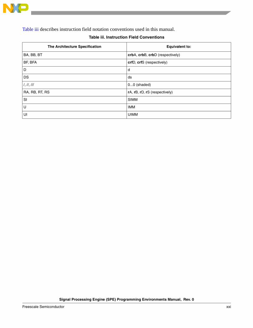
Table iii describes instruction field notation conventions used in this manual.
Table iii. Instruction Field Conventions
The Architecture Specification Equivalent to:
BA, BB, BT crbA, crbB, crbD (respectively)
BF, BFA crfD, crfS (respectively)
D d
DS ds
/, //, /// 0...0 (shaded)
RA, RB, RT, RS rA, rB, rD, rS (respectively)
SI SIMM
U IMM
UI UIMM

Signal Processing Engine (SPE) Programming Environments Manual, Rev. 0
xxii Freescale Semiconductor
Signal Processing Engine (SPE) Programming Environments Manual, Rev. 0
Freescale Semiconductor 1-1
Chapter 1 OverviewThis chapter provides a general description of the signal processing engine (SPE) and the SPE embedded floating-point resources defined as part of the Power ISA™ (instruction set architecture).
1.1 OverviewThe SPE is a 64-bit, two-element, single-instruction multiple-data (SIMD) ISA, originally designed to accelerate signal processing applications normally suited to DSP operation. The two-element vectors fit within GPRs extended to 64 bits. SPE also defines an accumulator register (ACC) to allow for back-to-back operations without loop unrolling. Like the VEC category, SPE is primarily an extension of Book I but identifies some resources for interrupt handling in Book III-E.
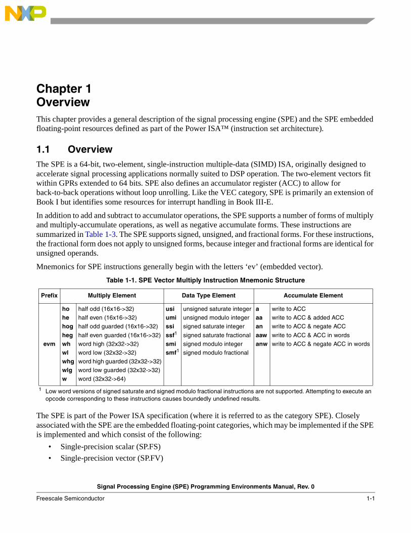
In addition to add and subtract to accumulator operations, the SPE supports a number of forms of multiply and multiply-accumulate operations, as well as negative accumulate forms. These instructions are summarized in Table 1-3. The SPE supports signed, unsigned, and fractional forms. For these instructions, the fractional form does not apply to unsigned forms, because integer and fractional forms are identical for unsigned operands.
Mnemonics for SPE instructions generally begin with the letters ‘ev’ (embedded vector).
The SPE is part of the Power ISA specification (where it is referred to as the category SPE). Closely associated with the SPE are the embedded floating-point categories, which may be implemented if the SPE is implemented and which consist of the following:
• Single-precision scalar (SP.FS)
• Single-precision vector (SP.FV)
Table 1-1. SPE Vector Multiply Instruction Mnemonic Structure
Prefix Multiply Element Data Type Element Accumulate Element
evm
ho he hoghegwh wl whgwlgw
half odd (16x16->32)
half even (16x16->32)
half odd guarded (16x16->32)
half even guarded (16x16->32)
word high (32x32->32)
word low (32x32->32)
word high guarded (32x32->32)
word low guarded (32x32->32)
word (32x32->64)
usiumississf1
smismf1
1 Low word versions of signed saturate and signed modulo fractional instructions are not supported. Attempting to execute an opcode corresponding to these instructions causes boundedly undefined results.
unsigned saturate integer
unsigned modulo integer
signed saturate integer
signed saturate fractional
signed modulo integer
signed modulo fractional
aaaanaawanw
write to ACC
write to ACC & added ACC
write to ACC & negate ACC
write to ACC & ACC in words
write to ACC & negate ACC in words
Overview
Signal Processing Engine (SPE) Programming Environments Manual, Rev. 0
1-2 Freescale Semiconductor
• Double-precision scalar (SP.FD)
The embedded floating-point categories provide floating-point operations compatible with IEEE Std 754™ to power- and space-sensitive embedded applications. As is true for all SPE categories, rather than implementing separate register floating-point registers (FPRs), these categories share the GPRs used for integer operations, extending them to 64 bits to support the vector single-precision and scalar double-precision categories. These extended GPRs are described in Section 2.2.1, “General-Purpose Registers (GPRs).”
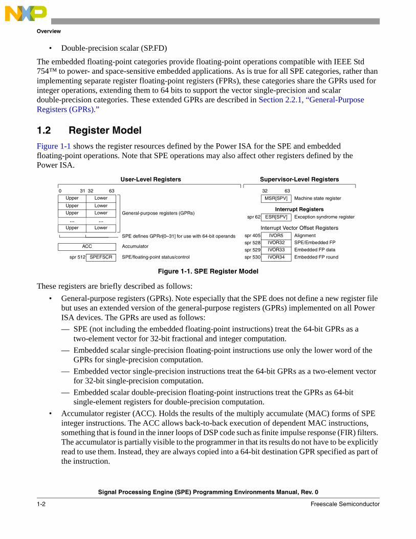
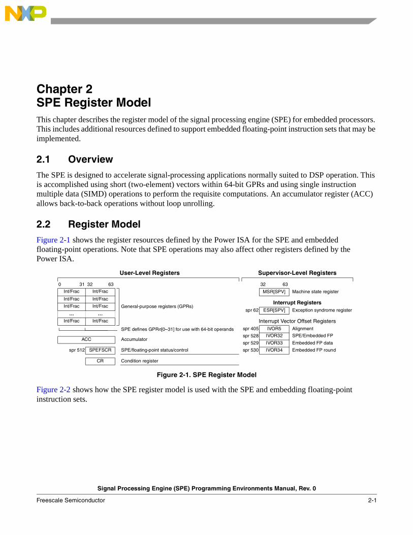
1.2 Register ModelFigure 1-1 shows the register resources defined by the Power ISA for the SPE and embedded floating-point operations. Note that SPE operations may also affect other registers defined by the Power ISA.
These registers are briefly described as follows:
• General-purpose registers (GPRs). Note especially that the SPE does not define a new register file but uses an extended version of the general-purpose registers (GPRs) implemented on all Power ISA devices. The GPRs are used as follows:
— SPE (not including the embedded floating-point instructions) treat the 64-bit GPRs as a two-element vector for 32-bit fractional and integer computation.
— Embedded scalar single-precision floating-point instructions use only the lower word of the GPRs for single-precision computation.
— Embedded vector single-precision instructions treat the 64-bit GPRs as a two-element vector for 32-bit single-precision computation.
— Embedded scalar double-precision floating-point instructions treat the GPRs as 64-bit single-element registers for double-precision computation.
• Accumulator register (ACC). Holds the results of the multiply accumulate (MAC) forms of SPE integer instructions. The ACC allows back-to-back execution of dependent MAC instructions, something that is found in the inner loops of DSP code such as finite impulse response (FIR) filters. The accumulator is partially visible to the programmer in that its results do not have to be explicitly read to use them. Instead, they are always copied into a 64-bit destination GPR specified as part of the instruction.
User-Level Registers Supervisor-Level Registers
0 31 32 63 32 63
Upper Lower
General-purpose registers (GPRs)
MSR[SPV] Machine state register
Upper LowerInterrupt Registers
Upper Lower spr 62 ESR[SPV] Exception syndrome register
… …
Upper Lower Interrupt Vector Offset Registers
SPE defines GPRn[0–31] for use with 64-bit operands spr 405 IVOR5 Alignment
spr 528 IVOR32 SPE/Embedded FPACC Accumulator
spr 529 IVOR33 Embedded FP data
SPE/floating-point status/control spr 512 SPEFSCR spr 530 IVOR34 Embedded FP round
Figure 1-1. SPE Register Model
Overview
Signal Processing Engine (SPE) Programming Environments Manual, Rev. 0
Freescale Semiconductor 1-3
• SPE floating-point status and control register (SPEFSCR). Used for status and control of SPE and embedded floating-point instructions. It controls the handling of floating-point exceptions and records status resulting from the floating-point operations.
• Interrupt vector offset registers (IVORs). The SPE uses four IVORs, which together with the interrupt vector prefix register (IVPR) define the vector address for interrupt handler routines. The following IVORs are used:
— IVOR5 (SPR 405)—Defined by the base architecture for alignment exceptions and used with SPE load and store instructions alignment interrupts.
— IVOR32 (SPR 528)—SPE/embedded floating-point unavailable exception (causes the SPE/embedded floating-point unavailable interrupt)
— IVOR33 (SPR 529)—Embedded floating-point data interrupts
— IVOR34 (SPR 530)—Embedded floating-point round interrupts
• SPE/embedded floating-point available bit in the machine state register (MSR[SPV], formerly called MSR[SPE]). If this bit is zero and software attempts to execute an SPE/embedded floating-point instruction, an SPE unavailable interrupt is taken.
• Exception bit in the exception syndrome register (ESR[SPV], formerly called ESR[SPE). This bit is set whenever the processor takes an interrupt related to the execution of SPE vector or floating-point instructions.
Chapter 2, “SPE Register Model,” provides detailed descriptions of these register resources.
1.2.1 SPE Instructions
.Instructions are provided for the instruction types:
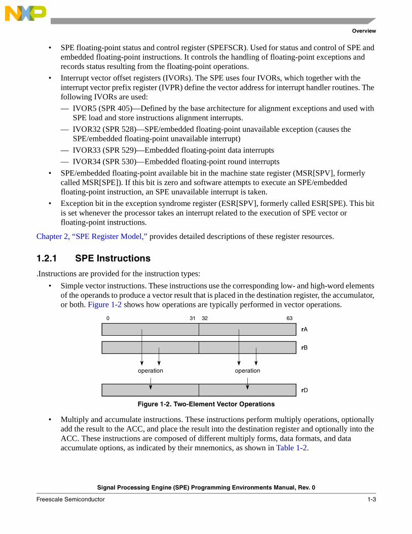
• Simple vector instructions. These instructions use the corresponding low- and high-word elements of the operands to produce a vector result that is placed in the destination register, the accumulator, or both. Figure 1-2 shows how operations are typically performed in vector operations.
Figure 1-2. Two-Element Vector Operations
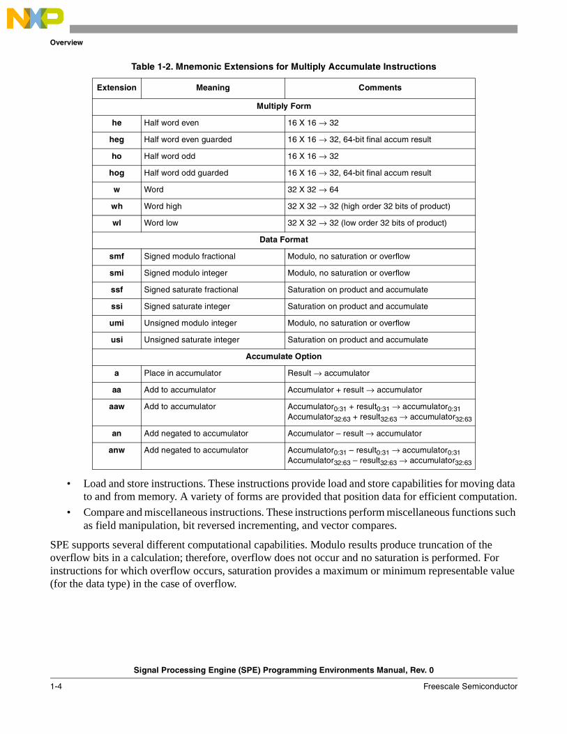
• Multiply and accumulate instructions. These instructions perform multiply operations, optionally add the result to the ACC, and place the result into the destination register and optionally into the ACC. These instructions are composed of different multiply forms, data formats, and data accumulate options, as indicated by their mnemonics, as shown in Table 1-2.
0 31 32 63
rA
rB
operation operation
rD
Overview
Signal Processing Engine (SPE) Programming Environments Manual, Rev. 0
1-4 Freescale Semiconductor
• Load and store instructions. These instructions provide load and store capabilities for moving data to and from memory. A variety of forms are provided that position data for efficient computation.
• Compare and miscellaneous instructions. These instructions perform miscellaneous functions such as field manipulation, bit reversed incrementing, and vector compares.
SPE supports several different computational capabilities. Modulo results produce truncation of the overflow bits in a calculation; therefore, overflow does not occur and no saturation is performed. For instructions for which overflow occurs, saturation provides a maximum or minimum representable value (for the data type) in the case of overflow.
Table 1-2. Mnemonic Extensions for Multiply Accumulate Instructions
Extension Meaning Comments
Multiply Form
he Half word even 16 X 16 → 32
heg Half word even guarded 16 X 16 → 32, 64-bit final accum result
ho Half word odd 16 X 16 → 32
hog Half word odd guarded 16 X 16 → 32, 64-bit final accum result
w Word 32 X 32 → 64
wh Word high 32 X 32 → 32 (high order 32 bits of product)
wl Word low 32 X 32 → 32 (low order 32 bits of product)
Data Format
smf Signed modulo fractional Modulo, no saturation or overflow
smi Signed modulo integer Modulo, no saturation or overflow
ssf Signed saturate fractional Saturation on product and accumulate
ssi Signed saturate integer Saturation on product and accumulate
umi Unsigned modulo integer Modulo, no saturation or overflow
usi Unsigned saturate integer Saturation on product and accumulate
Accumulate Option
a Place in accumulator Result → accumulator
aa Add to accumulator Accumulator + result → accumulator
aaw Add to accumulator Accumulator0:31 + result0:31 → accumulator0:31Accumulator32:63 + result32:63 → accumulator32:63
an Add negated to accumulator Accumulator – result → accumulator
anw Add negated to accumulator Accumulator0:31 – result0:31 → accumulator0:31Accumulator32:63 – result32:63 → accumulator32:63
Overview
Signal Processing Engine (SPE) Programming Environments Manual, Rev. 0
Freescale Semiconductor 1-5
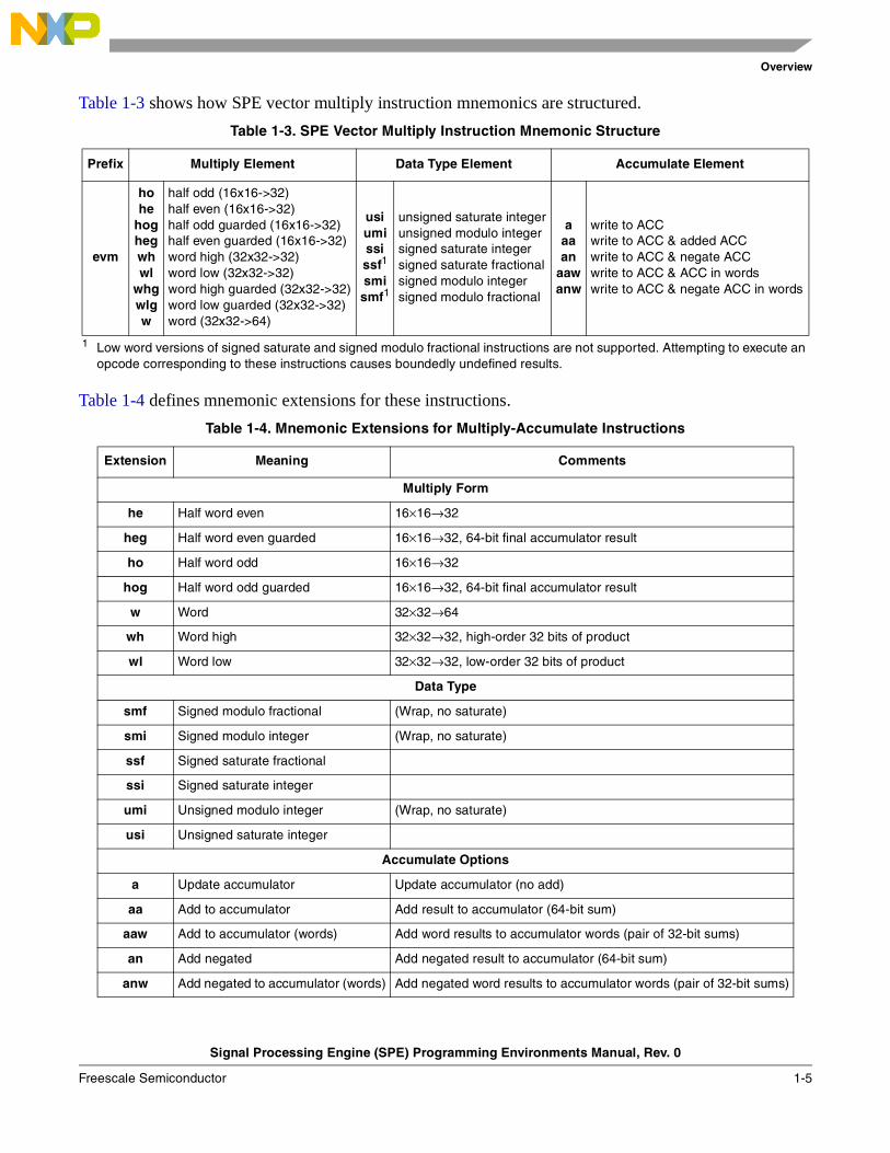
Table 1-3 shows how SPE vector multiply instruction mnemonics are structured.
Table 1-4 defines mnemonic extensions for these instructions.
Table 1-3. SPE Vector Multiply Instruction Mnemonic Structure
Prefix Multiply Element Data Type Element Accumulate Element
evm
ho he
hoghegwh wl
whgwlgw
half odd (16x16->32)half even (16x16->32)half odd guarded (16x16->32)half even guarded (16x16->32)word high (32x32->32)word low (32x32->32)word high guarded (32x32->32)word low guarded (32x32->32)word (32x32->64)
usiumississf1
smismf1
1 Low word versions of signed saturate and signed modulo fractional instructions are not supported. Attempting to execute an opcode corresponding to these instructions causes boundedly undefined results.
unsigned saturate integerunsigned modulo integersigned saturate integersigned saturate fractionalsigned modulo integersigned modulo fractional
aaaan
aawanw
write to ACCwrite to ACC & added ACCwrite to ACC & negate ACCwrite to ACC & ACC in wordswrite to ACC & negate ACC in words
Table 1-4. Mnemonic Extensions for Multiply-Accumulate Instructions
Extension Meaning Comments
Multiply Form
he Half word even 16×16→32
heg Half word even guarded 16×16→32, 64-bit final accumulator result
ho Half word odd 16×16→32
hog Half word odd guarded 16×16→32, 64-bit final accumulator result
w Word 32×32→64
wh Word high 32×32→32, high-order 32 bits of product
wl Word low 32×32→32, low-order 32 bits of product
Data Type
smf Signed modulo fractional (Wrap, no saturate)
smi Signed modulo integer (Wrap, no saturate)
ssf Signed saturate fractional
ssi Signed saturate integer
umi Unsigned modulo integer (Wrap, no saturate)
usi Unsigned saturate integer
Accumulate Options
a Update accumulator Update accumulator (no add)
aa Add to accumulator Add result to accumulator (64-bit sum)
aaw Add to accumulator (words) Add word results to accumulator words (pair of 32-bit sums)
an Add negated Add negated result to accumulator (64-bit sum)
anw Add negated to accumulator (words) Add negated word results to accumulator words (pair of 32-bit sums)
Overview
Signal Processing Engine (SPE) Programming Environments Manual, Rev. 0
1-6 Freescale Semiconductor
1.2.1.1 Embedded Vector and Scalar Floating-Point Instructions
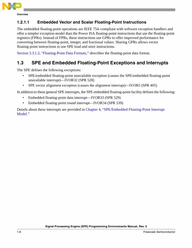
The embedded floating-point operations are IEEE 754–compliant with software exception handlers and offer a simpler exception model than the Power ISA floating-point instructions that use the floating-point registers (FPRs). Instead of FPRs, these instructions use GPRs to offer improved performance for converting between floating-point, integer, and fractional values. Sharing GPRs allows vector floating-point instructions to use SPE load and store instructions.
Section 3.3.1.2, “Floating-Point Data Formats,” describes the floating-point data format.
1.3 SPE and Embedded Floating-Point Exceptions and InterruptsThe SPE defines the following exceptions:
• SPE/embedded floating-point unavailable exception (causes the SPE/embedded floating-point unavailable interrupt)—IVOR32 (SPR 528)
• SPE vector alignment exception (causes the alignment interrupt)—IVOR5 (SPR 405)
In addition to these general SPE interrupts, the SPE embedded floating-point facility defines the following:
• Embedded floating-point data interrupt—IVOR33 (SPR 529)
• Embedded floating-point round interrupt—IVOR34 (SPR 539)
Details about these interrupts are provided in Chapter 4, “SPE/Embedded Floating-Point Interrupt Model.”
Signal Processing Engine (SPE) Programming Environments Manual, Rev. 0
Freescale Semiconductor 2-1
Chapter 2 SPE Register ModelThis chapter describes the register model of the signal processing engine (SPE) for embedded processors. This includes additional resources defined to support embedded floating-point instruction sets that may be implemented.
2.1 OverviewThe SPE is designed to accelerate signal-processing applications normally suited to DSP operation. This is accomplished using short (two-element) vectors within 64-bit GPRs and using single instruction multiple data (SIMD) operations to perform the requisite computations. An accumulator register (ACC) allows back-to-back operations without loop unrolling.
2.2 Register ModelFigure 2-1 shows the register resources defined by the Power ISA for the SPE and embedded floating-point operations. Note that SPE operations may also affect other registers defined by the Power ISA.
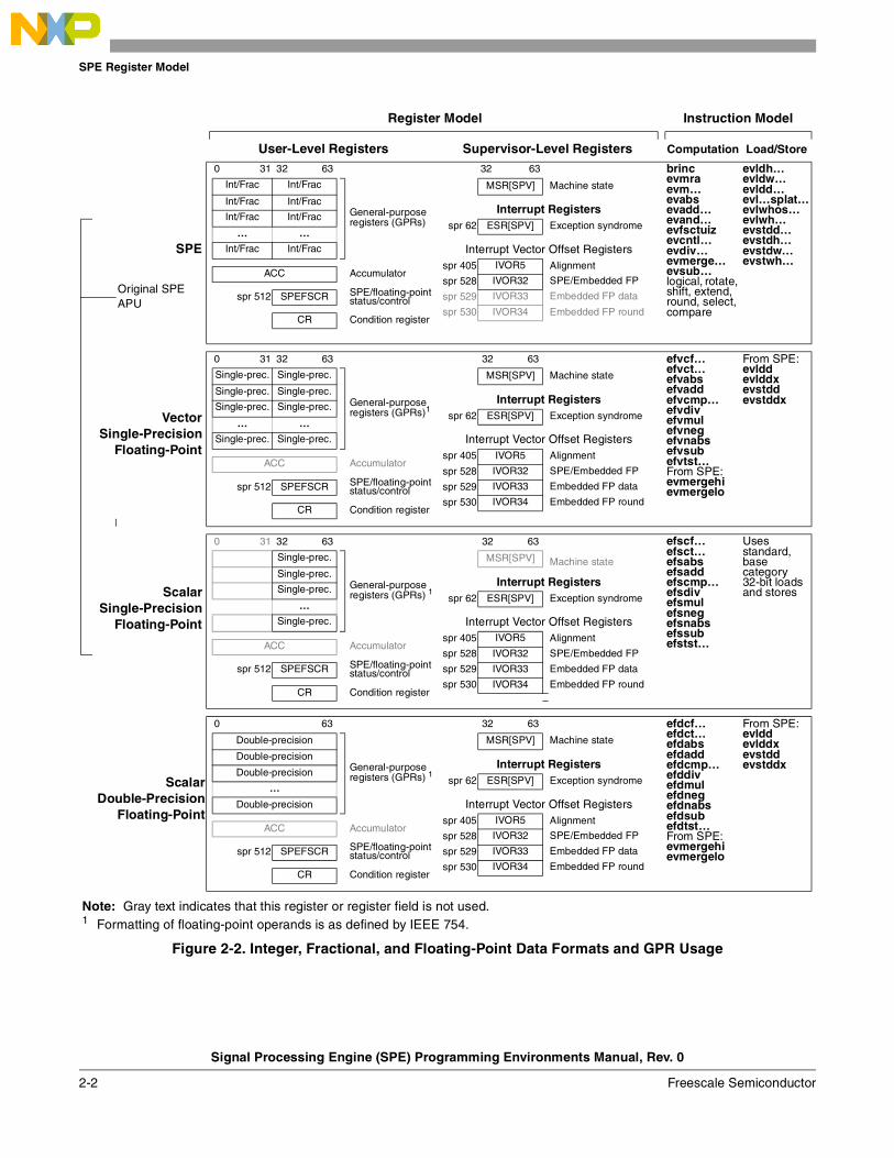
Figure 2-2 shows how the SPE register model is used with the SPE and embedding floating-point instruction sets.
User-Level Registers Supervisor-Level Registers
0 31 32 63 32 63
Int/Frac Int/Frac
General-purpose registers (GPRs)
MSR[SPV] Machine state register
Int/Frac Int/FracInterrupt Registers
Int/Frac Int/Frac spr 62 ESR[SPV] Exception syndrome register
… …
Int/Frac Int/Frac Interrupt Vector Offset Registers
SPE defines GPRn[0–31] for use with 64-bit operands spr 405 IVOR5 Alignment
spr 528 IVOR32 SPE/Embedded FPACC Accumulator
spr 529 IVOR33 Embedded FP data
spr 512 SPEFSCR SPE/floating-point status/control spr 530 IVOR34 Embedded FP round
CR Condition register
Figure 2-1. SPE Register Model
SPE Register Model
Signal Processing Engine (SPE) Programming Environments Manual, Rev. 0
2-2 Freescale Semiconductor
Register Model Instruction Model
User-Level Registers Supervisor-Level Registers Computation Load/Store
0 31 32 63 32 63 brinc evmraevm…evabs evadd…evand…evfsctuizevcntl…evdiv…evmerge…evsub… logical, rotate, shift, extend, round, select, compare
evldh…evldw…evldd…evl…splat…evlwhos…evlwh…evstdd…evstdh…evstdw…evstwh…
Int/Frac Int/Frac
General-purpose registers (GPRs)
MSR[SPV] Machine state
Int/Frac Int/FracInterrupt Registers
Int/Frac Int/Frac spr 62 ESR[SPV] Exception syndrome
SPE… …
Int/Frac Int/Frac Interrupt Vector Offset Registersspr 405 IVOR5 Alignment
ACC Accumulatorspr 528 IVOR32 SPE/Embedded FP
Original SPE APU
SPE/floating-pointstatus/control spr 512 SPEFSCR spr 529 IVOR33 Embedded FP data
spr 530 IVOR34 Embedded FP roundCR Condition register
VectorSingle-Precision
Floating-Point
0 31 32 63 32 63 efvcf… efvct…efvabs efvadd efvcmp… efvdiv efvmulefvneg efvnabsefvsubefvtst…From SPE: evmergehi evmergelo
From SPE: evlddevlddxevstddevstddx
Single-prec. Single-prec.
General-purpose registers (GPRs)1
MSR[SPV] Machine state
Single-prec. Single-prec.Interrupt Registers
Single-prec. Single-prec. spr 62 ESR[SPV] Exception syndrome
… …
Single-prec. Single-prec. Interrupt Vector Offset Registersspr 405 IVOR5 Alignment
ACC Accumulatorspr 528 IVOR32 SPE/Embedded FP
SPE/floating-pointstatus/control spr 512 SPEFSCR spr 529 IVOR33 Embedded FP data
spr 530 IVOR34 Embedded FP roundCR Condition register
ScalarSingle-Precision
Floating-Point
0 31 32 63 32 63 efscf… efsct…efsabs efsadd efscmp… efsdiv efsmulefsneg efsnabsefssubefstst…
Uses standard, base category 32-bit loads and stores
Single-prec.
General-purpose registers (GPRs) 1
MSR[SPV] Machine state Single-prec.
Interrupt RegistersSingle-prec.
spr 62 ESR[SPV] Exception syndrome…
Single-prec. Interrupt Vector Offset Registersspr 405 IVOR5 Alignment
ACC Accumulatorspr 528 IVOR32 SPE/Embedded FP
SPE/floating-pointstatus/control spr 512 SPEFSCR spr 529 IVOR33 Embedded FP data
spr 530 IVOR34 Embedded FP roundCR Condition register
ScalarDouble-Precision
Floating-Point
0 31 32 63 32 63 efdcf… efdct…efdabs efdadd efdcmp… efddiv efdmulefdneg efdnabsefdsubefdtst…From SPE: evmergehi evmergelo
From SPE:evlddevlddxevstddevstddx
Double-precision
General-purpose registers (GPRs) 1
MSR[SPV] Machine state
Double-precisionInterrupt Registers
Double-precision spr 62 ESR[SPV] Exception syndrome
…
Double-precision Interrupt Vector Offset Registersspr 405 IVOR5 Alignment
ACC Accumulatorspr 528 IVOR32 SPE/Embedded FP
SPE/floating-pointstatus/control spr 512 SPEFSCR spr 529 IVOR33 Embedded FP data
spr 530 IVOR34 Embedded FP roundCR Condition register
Note: Gray text indicates that this register or register field is not used. 1 Formatting of floating-point operands is as defined by IEEE 754.
Figure 2-2. Integer, Fractional, and Floating-Point Data Formats and GPR Usage
SPE Register Model
Signal Processing Engine (SPE) Programming Environments Manual, Rev. 0
Freescale Semiconductor 2-3
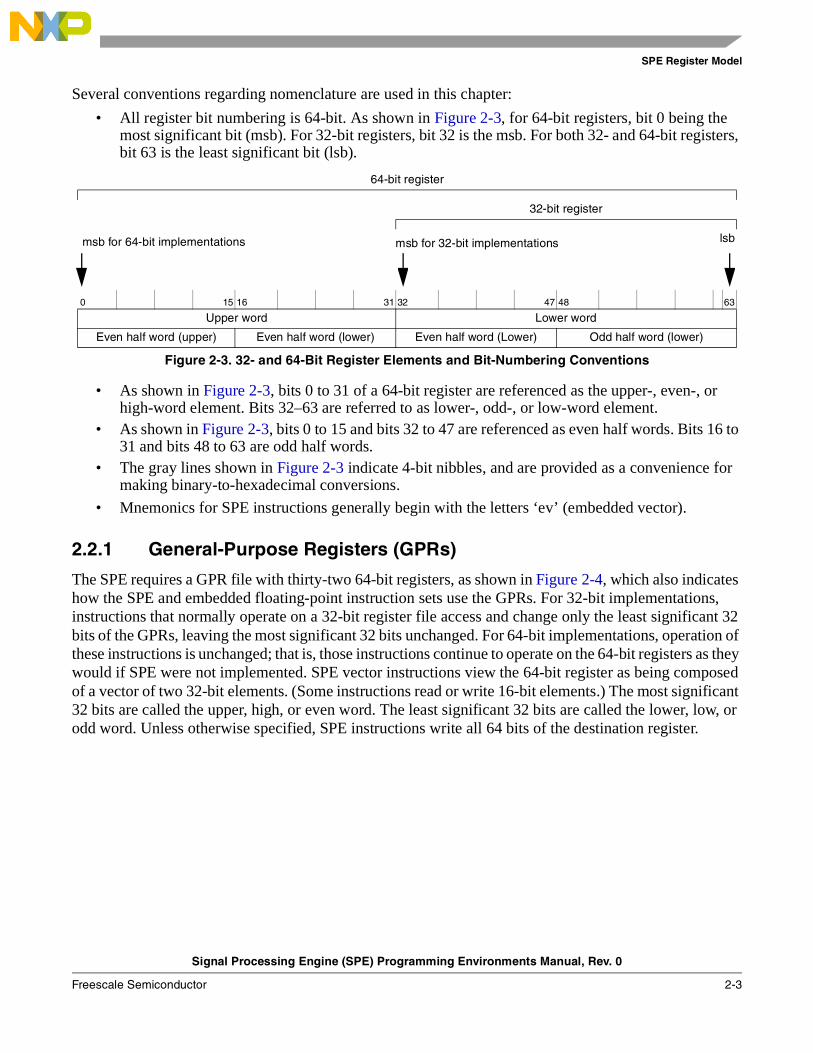
Several conventions regarding nomenclature are used in this chapter:
• All register bit numbering is 64-bit. As shown in Figure 2-3, for 64-bit registers, bit 0 being the most significant bit (msb). For 32-bit registers, bit 32 is the msb. For both 32- and 64-bit registers, bit 63 is the least significant bit (lsb).
• As shown in Figure 2-3, bits 0 to 31 of a 64-bit register are referenced as the upper-, even-, or high-word element. Bits 32–63 are referred to as lower-, odd-, or low-word element.
• As shown in Figure 2-3, bits 0 to 15 and bits 32 to 47 are referenced as even half words. Bits 16 to 31 and bits 48 to 63 are odd half words.
• The gray lines shown in Figure 2-3 indicate 4-bit nibbles, and are provided as a convenience for making binary-to-hexadecimal conversions.
• Mnemonics for SPE instructions generally begin with the letters ‘ev’ (embedded vector).
2.2.1 General-Purpose Registers (GPRs)
The SPE requires a GPR file with thirty-two 64-bit registers, as shown in Figure 2-4, which also indicates how the SPE and embedded floating-point instruction sets use the GPRs. For 32-bit implementations, instructions that normally operate on a 32-bit register file access and change only the least significant 32 bits of the GPRs, leaving the most significant 32 bits unchanged. For 64-bit implementations, operation of these instructions is unchanged; that is, those instructions continue to operate on the 64-bit registers as they would if SPE were not implemented. SPE vector instructions view the 64-bit register as being composed of a vector of two 32-bit elements. (Some instructions read or write 16-bit elements.) The most significant 32 bits are called the upper, high, or even word. The least significant 32 bits are called the lower, low, or odd word. Unless otherwise specified, SPE instructions write all 64 bits of the destination register.
64-bit register
32-bit register
msb for 64-bit implementations msb for 32-bit implementations lsb
0 15 16 31 32 47 48 63
Upper word Lower word
Even half word (upper) Even half word (lower) Even half word (Lower) Odd half word (lower)
Figure 2-3. 32- and 64-Bit Register Elements and Bit-Numbering Conventions
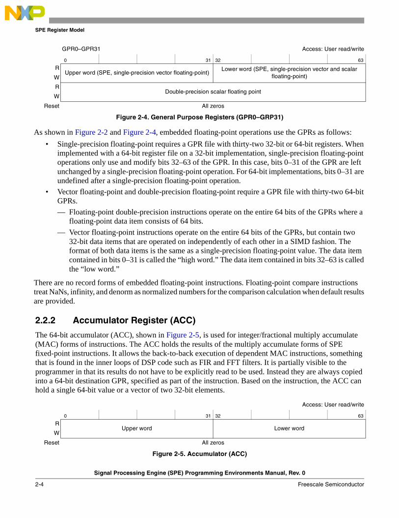
SPE Register Model
Signal Processing Engine (SPE) Programming Environments Manual, Rev. 0
2-4 Freescale Semiconductor
2.2.2 Accumulator Register (ACC)
The 64-bit accumulator (ACC), shown in Figure 2-5, is used for integer/fractional multiply accumulate (MAC) forms of instructions. The ACC holds the results of the multiply accumulate forms of SPE fixed-point instructions. It allows the back-to-back execution of dependent MAC instructions, something that is found in the inner loops of DSP code such as FIR and FFT filters. It is partially visible to the programmer in that its results do not have to be explicitly read to be used. Instead they are always copied into a 64-bit destination GPR, specified as part of the instruction. Based on the instruction, the ACC can hold a single 64-bit value or a vector of two 32-bit elements.
GPR0–GPR31 Access: User read/write
0 31 32 63
RUpper word (SPE, single-precision vector floating-point)
Lower word (SPE, single-precision vector and scalar floating-point)W
RDouble-precision scalar floating point
W
Reset All zeros
Figure 2-4. General Purpose Registers (GPR0–GRP31)
As shown in Figure 2-2 and Figure 2-4, embedded floating-point operations use the GPRs as follows:
• Single-precision floating-point requires a GPR file with thirty-two 32-bit or 64-bit registers. When implemented with a 64-bit register file on a 32-bit implementation, single-precision floating-point operations only use and modify bits 32–63 of the GPR. In this case, bits 0–31 of the GPR are left unchanged by a single-precision floating-point operation. For 64-bit implementations, bits 0–31 are undefined after a single-precision floating-point operation.
• Vector floating-point and double-precision floating-point require a GPR file with thirty-two 64-bit GPRs.
— Floating-point double-precision instructions operate on the entire 64 bits of the GPRs where a floating-point data item consists of 64 bits.
— Vector floating-point instructions operate on the entire 64 bits of the GPRs, but contain two 32-bit data items that are operated on independently of each other in a SIMD fashion. The format of both data items is the same as a single-precision floating-point value. The data item contained in bits 0–31 is called the “high word.” The data item contained in bits 32–63 is called the “low word.”
There are no record forms of embedded floating-point instructions. Floating-point compare instructions treat NaNs, infinity, and denorm as normalized numbers for the comparison calculation when default results are provided.
Access: User read/write
0 31 32 63
RUpper word Lower word
W
Reset All zeros
Figure 2-5. Accumulator (ACC)

SPE Register Model
Signal Processing Engine (SPE) Programming Environments Manual, Rev. 0
Freescale Semiconductor 2-5
2.2.3 Signal Processing Embedded Floating-Point Status andControl Register (SPEFSCR)
The SPEFSCR, shown in Figure 2-6, is used with SPE and embedded floating-point instructions. Vector floating-point instructions affect both the high element (bits 34–39) and low element floating-point status flags (bits 50–55). Double- and single-precision scalar floating-point instructions affect only the low-element floating-point status flags and leave the high-element floating-point status flags undefined.
Table 2-1 describes SPEFSCR bits.
SPR 512 Access: Supervisor-only
32 33 34 35 36 37 38 39 40 41 42 43 44 45 46 47
RSOVH OVH FGH FXH FINVH FDBZH FUNFH FOVFH — FINXS FINVS FDBZS FUNFS FOVFS —
W
Reset 0 0 undefined 0 0 0 0 0 0 0 0 0 0 0 0
48 49 50 51 52 53 54 55 56 57 58 59 60 61 62 63
RSOV OV FG FX FINV FDBZ FUNF FOVF — FINXE FINVE FDBZE FUNFE FOVFE FRMC
W
Reset 0 0 0 0 0 0 0 0 0 0 0 0 0 0 0 0
Figure 2-6. Signal Processing and Embedded Floating-Point Status and ControlRegister (SPEFSCR)
Table 2-1. SPEFSCR Field Descriptions
Bits Name Description
32 SOVH Summary integer overflow high. Set when an SPE instruction sets OVH. This is a sticky bit that remains set until it is cleared by an mtspr instruction.
33 OVH Integer overflow high. OVH is set to indicate that an overflow occurred in the upper element during execution of an SPE instruction. It is set if a result of an operation performed by the instruction cannot be represented in the number of bits into which the result is to be placed and is cleared otherwise. OVH is not altered by modulo instructions or by other instructions that cannot overflow.
34 FGH Embedded floating-point guard bit high. Used by the floating-point round interrupt handler. FGH is an extension of the low-order bits of the fractional result produced from a floating-point operation on the high word. FGH is zeroed if an overflow, underflow, or invalid input error is detected on the high element of a vector floating-point instruction. Execution of a scalar floating-point instruction leaves FGH undefined.
35 FXH Embedded floating-point inexact bit high. Used by the floating-point round interrupt handler. FXH is an extension of the low-order bits of the fractional result produced from a floating-point operation on the high word. FXH represents the logical OR of all of the bits shifted right from the guard bit when the fractional result is normalized. FXH is zeroed if an overflow, underflow, or invalid input error is detected on the high element of a vector floating-point instruction. Execution of a scalar floating-point instruction leaves FXH undefined.
High-Word Error Bits Status Bits
Enable Bits

SPE Register Model
Signal Processing Engine (SPE) Programming Environments Manual, Rev. 0
2-6 Freescale Semiconductor
36 FINVH Embedded floating-point invalid operation/input error high. Set under any of the following conditions: • Any operand of a high word vector floating-point instruction is infinity, NaN, or denorm • The operation is a divide and the dividend and divisor are both 0 • A conversion to integer or fractional value overflows.Execution of a scalar floating-point instruction leaves FINVH undefined.
37 FDBZH Embedded floating-point divide by zero high. Set when a vector floating-point divide instruction is executed with a divisor of 0 in the high word operand and the dividend is a finite non-zero number.Execution of a scalar floating-point instruction leaves FDBZH undefined.
38 FUNFH Embedded floating-point underflow high. Set when execution of a vector floating-point instruction results in an underflow on the high word operation.Execution of a scalar floating-point instruction leaves FUNFH undefined.
39 FOVFH Embedded floating-point overflow high. Set when the execution of a vector floating-point instruction results in an overflow on the high word operation.Execution of a scalar floating-point instruction leaves FOVFH undefined.
40–41 — Reserved, should be cleared.
42 FINXS Embedded floating-point inexact sticky flag. Set under the following conditions: • Execution of any scalar or vector floating-point instruction delivers an inexact result for either the low or high
element ,and no floating-point data interrupt is taken for either element. • A floating-point instruction results in overflow (FOVF=1 or FOVFH=1), but floating-point overflow exceptions
are disabled (FOVFE=0). • A floating-point instruction results in underflow (FUNF=1 or FUNFH=1), but floating-point underflow
exceptions are disabled (FUNFE=0), and no floating-point data interrupt occurs. FINXS is a sticky bit; it remains set until it is cleared by software.
43 FINVS Embedded floating-point invalid operation sticky flag. The sticky result of any floating-point instruction that causes FINVH or FINV to be set. That is, FINVS <- FINVS | FINV | FINVH. FINVS remains set until it is cleared by software. 1
44 FDBZS Embedded floating-point divide by zero sticky flag. Set when a floating-point divide instruction sets FDBZH or FDBZ. That is, FDBZS <- FDBZS | FDBZH | FDBZ. FDBZS remains set until it is cleared by software.
45 FUNFS Embedded floating-point underflow sticky flag. Defined to be the sticky result of any floating-point instruction that causes FUNFH or FUNF to be set. That is, FUNFS <- FUNFS | FUNF | FUNFH. FUNFS remains set until it is cleared by software. 1
46 FOVFS Embedded floating-point overflow sticky flag. defined to be the sticky result of any floating-point instruction that causes FOVH or FOVF to be set. That is, FOVFS <- FOVFS | FOVF | FOVFH. FOVFS remains set until it is cleared by software. 1
47 — Reserved, should be cleared.
48 SOV Summary integer overflow low. Set when an SPE instruction sets OV. This sticky bit remains set until an mtspr writes a 0 to this bit.
49 OV Integer overflow. Set to indicate that an overflow occurred in the lower element during instruction execution. OV is set if a result of an operation cannot be represented in the designated number of bits; otherwise, it is cleared. OV is unaffected by modulo instructions and other instructions that cannot overflow.
50 FG Embedded floating-point guard bit (low/scalar). Used by the embedded floating-point round interrupt handler. FG is an extension of the low-order bits of the fractional result produced from an embedded floating-point instruction on the low word. FG is zeroed if an overflow, underflow, or invalid input error is detected on the low element of an embedded floating-point instruction.
Table 2-1. SPEFSCR Field Descriptions (continued)
Bits Name Description
SPE Register Model
Signal Processing Engine (SPE) Programming Environments Manual, Rev. 0
Freescale Semiconductor 2-7
51 FX Embedded floating-point inexact bit (low/scalar). Used by the embedded floating-point round interrupt handler. FX is an extension of the low-order bits of the fractional result produced from an embedded floating-point instruction on the low word. FX represents the logical OR of all the bits shifted right from the guard bit when the fractional result is normalized. FX is zeroed if an overflow, underflow, or invalid input error is detected on embedded floating-point instruction.
52 FINV Embedded floating-point invalid operation/input error (low/scalar). Set by one of the following: • Any operand of a low-word vector or scalar floating-point operation is infinity, NaN, or denorm. • The dividend and divisor are both 0 for a divide operation. • A conversion to integer or fractional value overflows.
53 FDBZ Embedded floating-point divide by zero (low/scalar). Set when an embedded floating-point divide instruction is executed with a divisor of 0 in the low word operand, and the dividend is a finite nonzero number.
54 FUNF Embedded floating-point underflow (low/scalar). Set when the execution of an embedded floating-point instruction results in an underflow on the low word operation.
55 FOVF Embedded floating-point overflow (Low/scalar). Set when the execution of an embedded floating-point instruction results in an overflow on the low word operation.
56 — Reserved, should be cleared.
57 FINXE Embedded floating-point round (inexact) exception enable0 Exception disabled1 Exception enabled. A floating-point round interrupt is taken if no other interrupt is taken, and if FG | FGH |
FX | FXH (signifying an inexact result) is set as a result of a floating-point operation. If a floating-point instruction operation results in overflow or underflow and the corresponding underflow or overflow exception is disabled, a floating-point round interrupt is taken.
58 FINVE Embedded floating-point invalid operation/input error exception enable0 Exception disabled1 Exception enabled. A floating-point data interrupt is taken if a floating-point instruction sets FINV or FINVH.
59 FDBZE Embedded floating-point divide by zero exception enable0 Exception disabled1 Exception enabled. A floating-point data interrupt is taken if a floating-point instruction sets FDBZ or FDBZH.
60 FUNFE Embedded floating-point underflow exception enable0 Exception disabled1 Exception enabled. A floating-point data interrupt is taken if a floating-point instruction sets FUNF or FUNFH.
61 FOVFE Embedded floating-point overflow exception enable0 Exception disabled1 Exception enabled. A floating-point data interrupt is taken if a floating-point instruction sets FOVF or FOVFH.
62–63 FRMC Embedded floating-point rounding mode control00 Round to nearest01 Round toward zero10 Round toward +infinity. If this mode is not implemented, embedded floating-point round interrupts are
generated for every floating-point instruction for which rounding is indicated.11 Round toward -infinity. If this mode is not implemented, embedded floating-point round interrupts are generated for every floating-point instruction for which rounding is indicated.
1 Software note: Software can detect the hardware that manages this bit by performing an operation on a NaN and observing whether hardware sets this sticky bit. Alternatively, if it desired that software work on all processors supporting embedded floating-point, software should check the appropriate status bits and set the sticky bit. If hardware also performs this operation, the action is redundant.
Table 2-1. SPEFSCR Field Descriptions (continued)
Bits Name Description
SPE Register Model
Signal Processing Engine (SPE) Programming Environments Manual, Rev. 0
2-8 Freescale Semiconductor
2.2.3.1 Interrupt Vector Offset Registers (IVORs)
The SPE uses four IVORs which, together with the interrupt vector prefix register (IVPR), define the vector address for interrupt handler routines. The following IVORs are used:
• IVOR5 (SPR 405)—Defined by the base architecture for alignment interrupts and used for SPE load and store instructions alignment interrupts
• IVOR32 (SPR 528)—SPE/embedded floating-point unavailable exception (causes the SPE/embedded floating-point unavailable interrupt)
• IVOR33 (SPR 529)—Embedded floating-point data interrupts
• IVOR34 (SPR 530)—Embedded floating-point round interrupts
For more information, see Chapter 4, “SPE/Embedded Floating-Point Interrupt Model.”
2.2.3.2 Exception Bit in the Exception Syndrome Register (ESR)
ESR[SPV] (ESR[56]), formerly called ESR[SPE], is set whenever the processor takes an interrupt related to the execution of SPE vector or floating-point instructions.
2.2.3.3 Condition Register (CR)
The CR is used to record results for compare and test instructions. It also provides a source operand for the Vector Select (evsel) instruction. Table 2-2 lists SPE instructions that explicitly access CR bits (crS or crD).
Table 2-2 lists embedded floating-point instructions that explicitly access CR bits (crD).
Table 2-2. SPE Instructions that Use the CR
Instruction Mnemonic Syntax
Vector Compare Equal evcmpeq crD,rA,rB
Vector Compare Greater Than Signed evcmpgts crD,rA,rB
Vector Compare Greater Than Unsigned evcmpgtu crD,rA,rB
Vector Compare Less Than Signed evcmplts crD,rA,rB
Vector Compare Less Than Unsigned evcmpltu crD,rA,rB
Vector Select evsel rD,rA,rB,crS
Table 2-3. Embedded Floating-Point Instructions that Use the CR
InstructionSingle-Precision
Double- Precision Scalar SyntaxScalar Vector
Floating-Point Compare Equal efscmpeq evfscmpeq efdcmpeq crD,rA,rB
Floating-Point Compare Greater Than efscmpgt evfscmpgt efdcmpgt crD,rA,rB
Floating-Point Compare Less Than efscmplt evfscmplt efdcmplt crD,rA,rB
Floating-Point Test Equal efststeq evfststeq efdtsteq crD,rA,rB
Floating-Point Test Greater Than efststgt evfststgt efdtstgt crD,rA,rB
Floating-Point Test Less Than efststlt evfststlt efdtstlt crD,rA,rB
SPE Register Model
Signal Processing Engine (SPE) Programming Environments Manual, Rev. 0
Freescale Semiconductor 2-9
2.2.3.4 SPE Available Bit in the Machine State Register (MSR)
MSR[SPV] (MSR[38]), formerly called MSR[SPE], is the SPE/embedded floating-point available bit. If this bit is zero and software attempts to execute an SPE instruction, an SPE unavailable interrupt is taken.
NOTE (Software)Software can use MSR[SPV] to detect when a process uses the upper 32 bits of a 64-bit register on a 32-bit implementation and thus save them on context switch.

SPE Register Model
Signal Processing Engine (SPE) Programming Environments Manual, Rev. 0
2-10 Freescale Semiconductor
Signal Processing Engine (SPE) Programming Environments Manual, Rev. 0
Freescale Semiconductor 3-1
Chapter 3 SPE and Embedded Floating-Point Instruction ModelThis chapter describes the instruction model of the signal processing engine (SPE) for embedded processors. This includes additional resources defined to support embedded floating-point instruction sets that may be implemented.
Chapter 5, “Instruction Set,” gives complete descriptions of individual SPE and embedded floating-point instructions. Section 5.3.1, “SPE Saturation and Bit-Reverse Models,” provides pseudo-RTL for saturation and bit reversal to more accurately describe those functions that are referenced in the instruction pseudo-RTL.
3.1 OverviewThe SPE is designed to accelerate signal-processing applications normally suited to DSP operation. This is accomplished using short (two-element) vectors within 64-bit GPRs and using single instruction multiple data (SIMD) operations to perform the requisite computations. An accumulator register (ACC) allows back-to-back operations without loop unrolling.
The SPE defines both computational and load store instructions. SPE load store instructions are necessary for 32-bit implementation to access 64-bit operands.
Embedded floating-point instructions, which may be implemented if the SPE is implemented, include the following computational instructions:
• Embedded vector single-precision floating-point, which use extended 64-bit GPRs
• Embedded scalar single-precision floating-point, which use extended 32-bit GPRs
• Embedded scalar double-precision floating-point, which use extended 64-bit GPRs
Note that for 32-bit implementations, the SPE load and store instructions must be used for accessing 64-bit embedded floating-point operands.
3.2 SPE Instruction SetThis section describes the data formats and instruction syntax, and provides an overview of computational operations of the SPE instructions.
Chapter 5, “Instruction Set,” gives complete descriptions of individual SPE and embedded floating-point instructions.
Opcodes are listed in Appendix B, “SPE and Embedded Floating-Point Opcode Listings.”
SPE and Embedded Floating-Point Instruction Model
Signal Processing Engine (SPE) Programming Environments Manual, Rev. 0
3-2 Freescale Semiconductor
3.2.1 SPE Data Formats
SPE provides integer and fractional data formats, which can be treated as signed or unsigned quantities.
3.2.1.1 Integer Format
Unsigned integers consist of 16-, 32-, or 64-bit binary integer values. The largest representable value is 2n – 1, where n represents the number of bits in the value. The smallest representable value is 0. Computations that produce values larger than 2n – 1 or smaller than 0 set OV or OVH in SPEFSCR.
Signed integers consist of 16-, 32-, or 64-bit binary values in two’s-complement form. The largest representable value is 2n–1 – 1, where n represents the number of bits in the value. The smallest representable value is –2n–1. Computations that produce values larger than 2n–1 – 1 or smaller than –2n–1 set OV or OVH in SPEFSCR.
3.2.1.2 Fractional Format
Fractional data is useful for representing data converted from analog devices and is conventionally used for DSP fractional arithmetic.
Unsigned fractions consist of 16-, 32-, or 64-bit binary fractional values that range from 0 to less than 1. Unsigned fractions place the radix point immediately to the left of the msb. The msb of the value represents the value 2-1, the next msb represents the value 2-2, and so on. The largest representable value is 1-2-n where n represents the number of bits in the value. The smallest representable value is 0. Computations that produce values larger than 1-2-n or smaller than 0 may set OV or OVH in the SPEFSCR. SPE does not define unsigned fractional forms of instructions to manipulate unsigned fractional data because the unsigned integer forms of the instructions produce the same results as unsigned fractional forms.
Guarded unsigned fractions are 64-bit binary fractional values. Guarded unsigned fractions place the decimal point immediately to the left of bit 32. The largest representable value is 232-2-32; the smallest is 0. Guarded unsigned fractional computations are always modulo and do not set OV or OVH.
Signed fractions consist of 16-, 32-, or 64-bit binary fractional values in two’s-complement form that range from -1 to less than 1. Signed fractions place the decimal point immediately to the right of the msb. The largest representable value is 1-2-(n-1) where n represents the number of bits in the value. The smallest representable value is -1. Computations that produce values larger than 1-2-(n-1) or smaller than -1 may set OV or OVH. Multiplication of two signed fractional values causes the result to be shifted left one bit to remove the resultant redundant sign bit in the product. In this case, a 0 bit is concatenated as the lsb of the shifted result.
Guarded signed fractions are 64-bit binary fractional values that place the decimal point immediately to the left of bit 33. The largest representable value is 232-2-31; the smallest is -232-1+2-31. Guarded signed fractional computations are always modulo and do not set OV or OVH.
3.2.2 Computational Operations
SPE supports several different computational capabilities. Modulo results produce truncation of the overflow bits in a calculation; therefore, overflow does not occur and no saturation is performed. For instructions for which overflow occurs, saturation provides a maximum or minimum representable value
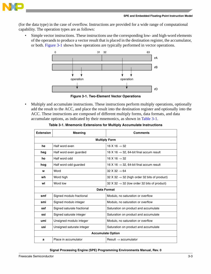
SPE and Embedded Floating-Point Instruction Model
Signal Processing Engine (SPE) Programming Environments Manual, Rev. 0
Freescale Semiconductor 3-3
(for the data type) in the case of overflow. Instructions are provided for a wide range of computational capability. The operation types are as follows:
• Simple vector instructions. These instructions use the corresponding low- and high-word elements of the operands to produce a vector result that is placed in the destination register, the accumulator, or both. Figure 3-1 shows how operations are typically performed in vector operations.
Figure 3-1. Two-Element Vector Operations
• Multiply and accumulate instructions. These instructions perform multiply operations, optionally add the result to the ACC, and place the result into the destination register and optionally into the ACC. These instructions are composed of different multiply forms, data formats, and data accumulate options, as indicated by their mnemonics, as shown in Table 3-1.
Table 3-1. Mnemonic Extensions for Multiply Accumulate Instructions
Extension Meaning Comments
Multiply Form
he Half word even 16 X 16 → 32
heg Half word even guarded 16 X 16 → 32, 64-bit final accum result
ho Half word odd 16 X 16 → 32
hog Half word odd guarded 16 X 16 → 32, 64-bit final accum result
w Word 32 X 32 → 64
wh Word high 32 X 32 → 32 (high order 32 bits of product)
wl Word low 32 X 32 → 32 (low order 32 bits of product)
Data Format
smf Signed modulo fractional Modulo, no saturation or overflow
smi Signed modulo integer Modulo, no saturation or overflow
ssf Signed saturate fractional Saturation on product and accumulate
ssi Signed saturate integer Saturation on product and accumulate
umi Unsigned modulo integer Modulo, no saturation or overflow
usi Unsigned saturate integer Saturation on product and accumulate
Accumulate Option
a Place in accumulator Result → accumulator
0 31 32 63
rA
rB
operation operation
rD
SPE and Embedded Floating-Point Instruction Model
Signal Processing Engine (SPE) Programming Environments Manual, Rev. 0
3-4 Freescale Semiconductor
• Load and store instructions. These instructions provide load and store capabilities for moving data to and from memory. A variety of forms are provided that position data for efficient computation.
• Compare and miscellaneous instructions. These instructions perform miscellaneous functions such as field manipulation, bit reversed incrementing, and vector compares.
3.2.2.1 Data Formats and Register Usage
Figure 2-4 shows how GPRs are used with integer, fractional, and floating-point data formats.
3.2.2.1.1 Signed Fractions
In signed fractional format, the n-bit operand is represented in a 1.[n–1] format (1 sign bit, n–1 fraction bits). Signed fractional numbers are in the following range:
The real value of the binary operand SF[0:n-1] is as follows:
The most negative and positive numbers representable in fractional format are as follows:
• The most negative number is represented by SF(0) = 1 and SF[1:n–1] = 0 (that is, n=32; 0x8000_0000 = –1.0).
• The most positive number is represented by SF(0) = 0 and SF[1:n–1] = all 1s (that is, n = 32; 0x7FFF_FFFF = 1.0 - 2–(n–1)).
3.2.2.1.2 SPE Integer and Fractional Operations
Figure 3-2 shows data formats for signed integer and fractional multiplication. Note that low word versions of signed saturate and signed modulo fractional instructions are not supported. Attempting to execute an opcode corresponding to these instructions causes boundedly undefined results.
aa Add to accumulator Accumulator + result → accumulator
aaw Add to accumulator Accumulator0:31 + result0:31 → accumulator0:31Accumulator32:63 + result32:63 → accumulator32:63
an Add negated to accumulator Accumulator – result → accumulator
anw Add negated to accumulator Accumulator0:31 – result0:31 → accumulator0:31Accumulator32:63 – result32:63 → accumulator32:63
Table 3-1. Mnemonic Extensions for Multiply Accumulate Instructions (continued)
Extension Meaning Comments
1.0 SF 1.0 2n 1–( )–
–≤ ≤–
SF 1.0 SF 0( )•–= SF i( ) 2i–•
i 1=
n 1–
∑+
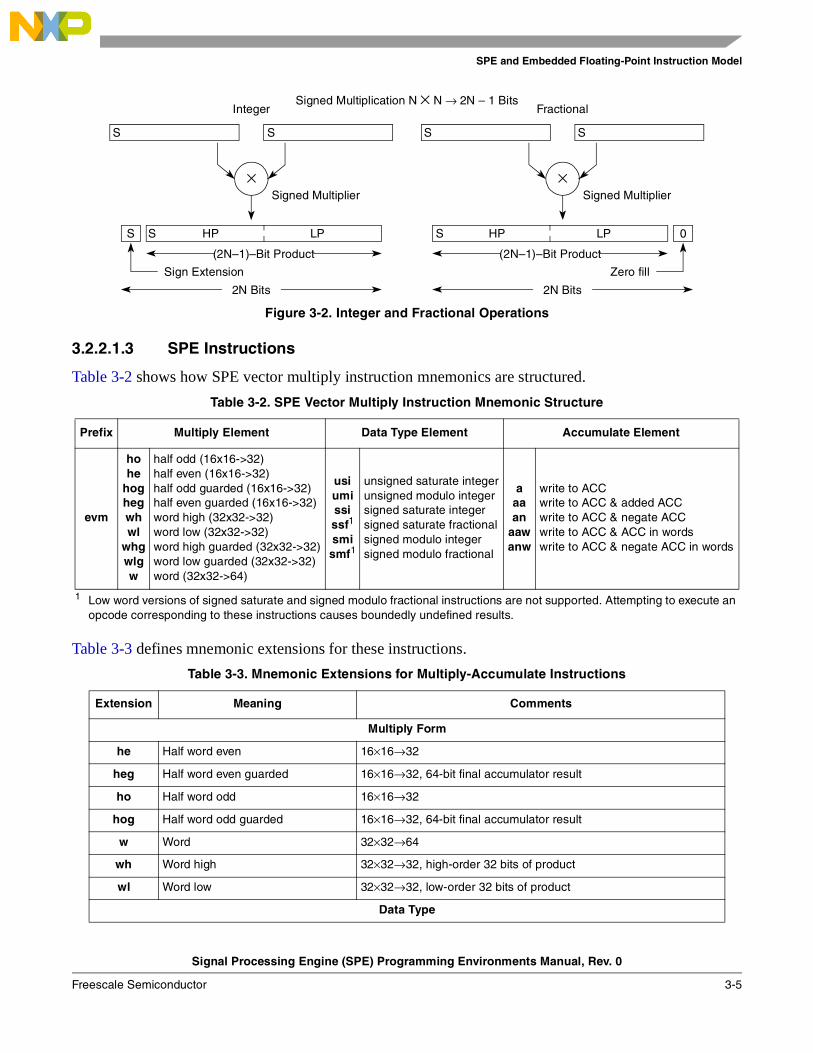
SPE and Embedded Floating-Point Instruction Model
Signal Processing Engine (SPE) Programming Environments Manual, Rev. 0
Freescale Semiconductor 3-5
Figure 3-2. Integer and Fractional Operations
3.2.2.1.3 SPE Instructions
Table 3-2 shows how SPE vector multiply instruction mnemonics are structured.
Table 3-3 defines mnemonic extensions for these instructions.
Table 3-2. SPE Vector Multiply Instruction Mnemonic Structure
Prefix Multiply Element Data Type Element Accumulate Element
evm
ho he
hoghegwh wl
whgwlgw
half odd (16x16->32)half even (16x16->32)half odd guarded (16x16->32)half even guarded (16x16->32)word high (32x32->32)word low (32x32->32)word high guarded (32x32->32)word low guarded (32x32->32)word (32x32->64)
usiumississf1
smismf1
1 Low word versions of signed saturate and signed modulo fractional instructions are not supported. Attempting to execute an opcode corresponding to these instructions causes boundedly undefined results.
unsigned saturate integerunsigned modulo integersigned saturate integersigned saturate fractionalsigned modulo integersigned modulo fractional
aaaan
aawanw
write to ACCwrite to ACC & added ACCwrite to ACC & negate ACCwrite to ACC & ACC in wordswrite to ACC & negate ACC in words
Table 3-3. Mnemonic Extensions for Multiply-Accumulate Instructions
Extension Meaning Comments
Multiply Form
he Half word even 16×16→32
heg Half word even guarded 16×16→32, 64-bit final accumulator result
ho Half word odd 16×16→32
hog Half word odd guarded 16×16→32, 64-bit final accumulator result
w Word 32×32→64
wh Word high 32×32→32, high-order 32 bits of product
wl Word low 32×32→32, low-order 32 bits of product
Data Type
S S
×
S S HP LP
2N Bits
(2N–1)–Bit Product
Signed Multiplier
Sign Extension
S S
×
0S HP LP
2N Bits
(2N–1)–Bit Product
Signed Multiplier
Zero fill
Integer FractionalSigned Multiplication N × N → 2N – 1 Bits
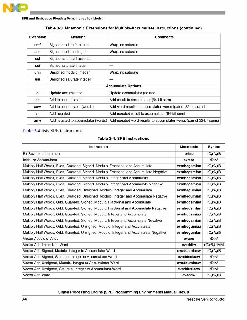
SPE and Embedded Floating-Point Instruction Model
Signal Processing Engine (SPE) Programming Environments Manual, Rev. 0
3-6 Freescale Semiconductor
Table 3-4 lists SPE instructions.
smf Signed modulo fractional Wrap, no saturate
smi Signed modulo integer Wrap, no saturate
ssf Signed saturate fractional —
ssi Signed saturate integer —
umi Unsigned modulo integer Wrap, no saturate
usi Unsigned saturate integer —
Accumulate Options
a Update accumulator Update accumulator (no add)
aa Add to accumulator Add result to accumulator (64-bit sum)
aaw Add to accumulator (words) Add word results to accumulator words (pair of 32-bit sums)
an Add negated Add negated result to accumulator (64-bit sum)
anw Add negated to accumulator (words) Add negated word results to accumulator words (pair of 32-bit sums)
Table 3-4. SPE Instructions
Instruction Mnemonic Syntax
Bit Reversed Increment brinc rD,rA,rB
Initialize Accumulator evmra rD,rA
Multiply Half Words, Even, Guarded, Signed, Modulo, Fractional and Accumulate evmhegsmfaa rD,rA,rB
Multiply Half Words, Even, Guarded, Signed, Modulo, Fractional and Accumulate Negative evmhegsmfan rD,rA,rB
Multiply Half Words, Even, Guarded, Signed, Modulo, Integer and Accumulate evmhegsmiaa rD,rA,rB
Multiply Half Words, Even, Guarded, Signed, Modulo, Integer and Accumulate Negative evmhegsmian rD,rA,rB
Multiply Half Words, Even, Guarded, Unsigned, Modulo, Integer and Accumulate evmhegumiaa rD,rA,rB
Multiply Half Words, Even, Guarded, Unsigned, Modulo, Integer and Accumulate Negative evmhegumian rD,rA,rB
Multiply Half Words, Odd, Guarded, Signed, Modulo, Fractional and Accumulate evmhogsmfaa rD,rA,rB
Multiply Half Words, Odd, Guarded, Signed, Modulo, Fractional and Accumulate Negative evmhogsmfan rD,rA,rB
Multiply Half Words, Odd, Guarded, Signed, Modulo, Integer and Accumulate evmhogsmiaa rD,rA,rB
Multiply Half Words, Odd, Guarded, Signed, Modulo, Integer and Accumulate Negative evmhogsmian rD,rA,rB
Multiply Half Words, Odd, Guarded, Unsigned, Modulo, Integer and Accumulate evmhogumiaa rD,rA,rB
Multiply Half Words, Odd, Guarded, Unsigned, Modulo, Integer and Accumulate Negative evmhogumian rD,rA,rB
Vector Absolute Value evabs rD,rA
Vector Add Immediate Word evaddiw rD,rB,UIMM
Vector Add Signed, Modulo, Integer to Accumulator Word evaddsmiaaw rD,rA,rB
Vector Add Signed, Saturate, Integer to Accumulator Word evaddssiaaw rD,rA
Vector Add Unsigned, Modulo, Integer to Accumulator Word evaddumiaaw rD,rA
Vector Add Unsigned, Saturate, Integer to Accumulator Word evaddusiaaw rD,rA
Vector Add Word evaddw rD,rA,rB
Table 3-3. Mnemonic Extensions for Multiply-Accumulate Instructions (continued)
Extension Meaning Comments

SPE and Embedded Floating-Point Instruction Model
Signal Processing Engine (SPE) Programming Environments Manual, Rev. 0
Freescale Semiconductor 3-7
Vector AND evand rD,rA,rB
Vector AND with Complement evandc rD,rA,rB
Vector Compare Equal evcmpeq crD,rA,rB
Vector Compare Greater Than Signed evcmpgts crD,rA,rB
Vector Compare Greater Than Unsigned evcmpgtu crD,rA,rB
Vector Compare Less Than Signed evcmplts crD,rA,rB
Vector Compare Less Than Unsigned evcmpltu crD,rA,rB
Vector Count Leading Sign Bits Word evcntlsw rD,rA
Vector Count Leading Zeros Word evcntlzw rD,rA
Vector Divide Word Signed evdivws rD,rA,rB
Vector Divide Word Unsigned evdivwu rD,rA,rB
Vector Equivalent eveqv rD,rA,rB
Vector Extend Sign Byte evextsb rD,rA
Vector Extend Sign Half Word evextsh rD,rA
Vector Load Double into Half Words evldh rD,d(rA)
Vector Load Double into Half Words Indexed evldhx rD,rA,rB
Vector Load Double into Two Words evldw rD,d(rA)
Vector Load Double into Two Words Indexed evldwx rD,rA,rB
Vector Load Double Word into Double Word evldd rD,d(rA)
Vector Load Double Word into Double Word Indexed evlddx rD,rA,rB
Vector Load Half Word into Half Word Odd Signed and Splat evlhhossplat rD,d(rA)
Vector Load Half Word into Half Word Odd Signed and Splat Indexed evlhhossplatx rD,rA,rB
Vector Load Half Word into Half Word Odd Unsigned and Splat evlhhousplat rD,d(rA)
Vector Load Half Word into Half Word Odd Unsigned and Splat Indexed evlhhousplatx rD,rA,rB
Vector Load Half Word into Half Words Even and Splat evlhhesplat rD,d(rA)
Vector Load Half Word into Half Words Even and Splat Indexed evlhhesplatx rD,rA,rB
Vector Load Word into Half Words and Splat evlwhsplat rD,d(rA)
Vector Load Word into Half Words and Splat Indexed evlwhsplatx rD,rA,rB
Vector Load Word into Half Words Odd Signed (with sign extension) evlwhos rD,d(rA)
Vector Load Word into Half Words Odd Signed Indexed (with sign extension) evlwhosx rD,rA,rB
Vector Load Word into Two Half Words Even evlwhe rD,d(rA)
Vector Load Word into Two Half Words Even Indexed evlwhex rD,rA,rB
Vector Load Word into Two Half Words Odd Unsigned (zero-extended) evlwhou rD,d(rA)
Vector Load Word into Two Half Words Odd Unsigned Indexed (zero-extended) evlwhoux rD,rA,rB
Vector Load Word into Word and Splat evlwwsplat rD,d(rA)
Vector Load Word into Word and Splat Indexed evlwwsplatx rD,rA,rB
Vector Merge High evmergehi rD,rA,rB
Vector Merge High/Low evmergehilo rD,rA,rB
Vector Merge Low evmergelo rD,rA,rB
Vector Merge Low/High evmergelohi rD,rA,rB
Table 3-4. SPE Instructions (continued)
Instruction Mnemonic Syntax

SPE and Embedded Floating-Point Instruction Model
Signal Processing Engine (SPE) Programming Environments Manual, Rev. 0
3-8 Freescale Semiconductor
Vector Multiply Half Words, Even, Signed, Modulo, Fractional evmhesmf rD,rA,rB
Vector Multiply Half Words, Even, Signed, Modulo, Fractional and Accumulate into Words evmhesmfaaw rD,rA,rB
Vector Multiply Half Words, Even, Signed, Modulo, Fractional and Accumulate Negative into Words
evmhesmfanw rD,rA,rB
Vector Multiply Half Words, Even, Signed, Modulo, Fractional, Accumulate evmhesmfa rD,rA,rB
Vector Multiply Half Words, Even, Signed, Modulo, Integer evmhesmi rD,rA,rB
Vector Multiply Half Words, Even, Signed, Modulo, Integer and Accumulate into Words evmhesmiaaw rD,rA,rB
Vector Multiply Half Words, Even, Signed, Modulo, Integer and Accumulate Negative into Words evmhesmianw rD,rA,rB
Vector Multiply Half Words, Even, Signed, Modulo, Integer, Accumulate evmhesmia rD,rA,rB
Vector Multiply Half Words, Even, Signed, Saturate, Fractional evmhessf rD,rA,rB
Vector Multiply Half Words, Even, Signed, Saturate, Fractional and Accumulate into Words evmhessfaaw rD,rA,rB
Vector Multiply Half Words, Even, Signed, Saturate, Fractional and Accumulate Negative into Words
evmhessfanw rD,rA,rB
Vector Multiply Half Words, Even, Signed, Saturate, Fractional, Accumulate evmhessfa rD,rA,rB
Vector Multiply Half Words, Even, Signed, Saturate, Integer and Accumulate into Words evmhessiaaw rD,rA,rB
Vector Multiply Half Words, Even, Signed, Saturate, Integer and Accumulate Negative into Words
evmhessianw rD,rA,rB
Vector Multiply Half Words, Even, Unsigned, Modulo, Integer evmheumi rD,rA,rB
Vector Multiply Half Words, Even, Unsigned, Modulo, Integer and Accumulate into Words evmheumiaaw rD,rA,rB
Vector Multiply Half Words, Even, Unsigned, Modulo, Integer and Accumulate Negative into Words
evmheumianw rD,rA,rB
Vector Multiply Half Words, Even, Unsigned, Modulo, Integer, Accumulate evmheumia rD,rA,rB
Vector Multiply Half Words, Even, Unsigned, Saturate, Integer and Accumulate into Words evmheusiaaw rD,rA,rB
Vector Multiply Half Words, Even, Unsigned, Saturate, Integer and Accumulate Negative into Words
evmheusianw rD,rA,rB
Vector Multiply Half Words, Odd, Signed, Modulo, Fractional evmhosmf rD,rA,rB
Vector Multiply Half Words, Odd, Signed, Modulo, Fractional and Accumulate into Words evmhosmfaaw rD,rA,rB
Vector Multiply Half Words, Odd, Signed, Modulo, Fractional and Accumulate Negative into Words
evmhosmfanw rD,rA,rB
Vector Multiply Half Words, Odd, Signed, Modulo, Fractional, Accumulate evmhosmfa rD,rA,rB
Vector Multiply Half Words, Odd, Signed, Modulo, Integer evmhosmi rD,rA,rB
Vector Multiply Half Words, Odd, Signed, Modulo, Integer and Accumulate into Words evmhosmiaaw rD,rA,rB
Vector Multiply Half Words, Odd, Signed, Modulo, Integer and Accumulate Negative into Words evmhosmianw rD,rA,rB
Vector Multiply Half Words, Odd, Signed, Modulo, Integer, Accumulate evmhosmia rD,rA,rB
Vector Multiply Half Words, Odd, Signed, Saturate, Fractional evmhossf rD,rA,rB
Vector Multiply Half Words, Odd, Signed, Saturate, Fractional and Accumulate into Words evmhossfaaw rD,rA,rB
Vector Multiply Half Words, Odd, Signed, Saturate, Fractional and Accumulate Negative into Words
evmhossfanw rD,rA,rB
Vector Multiply Half Words, Odd, Signed, Saturate, Fractional, Accumulate evmhossfa rD,rA,rB
Vector Multiply Half Words, Odd, Signed, Saturate, Integer and Accumulate into Words evmhossiaaw rD,rA,rB
Vector Multiply Half Words, Odd, Signed, Saturate, Integer and Accumulate Negative into Words evmhossianw rD,rA,rB
Table 3-4. SPE Instructions (continued)
Instruction Mnemonic Syntax

SPE and Embedded Floating-Point Instruction Model
Signal Processing Engine (SPE) Programming Environments Manual, Rev. 0
Freescale Semiconductor 3-9
Vector Multiply Half Words, Odd, Unsigned, Modulo, Integer evmhoumi rD,rA,rB
Vector Multiply Half Words, Odd, Unsigned, Modulo, Integer and Accumulate into Words evmhoumiaaw rD,rA,rB
Vector Multiply Half Words, Odd, Unsigned, Modulo, Integer and Accumulate Negative into Words
evmhoumianw rD,rA,rB
Vector Multiply Half Words, Odd, Unsigned, Modulo, Integer, Accumulate evmhoumia rD,rA,rB
Vector Multiply Half Words, Odd, Unsigned, Saturate, Integer and Accumulate into Words evmhousiaaw rD,rA,rB
Vector Multiply Half Words, Odd, Unsigned, Saturate, Integer and Accumulate Negative into Words
evmhousianw rD,rA,rB
Vector Multiply Word High Signed, Modulo, Fractional evmwhsmf rD,rA,rB
Vector Multiply Word High Signed, Modulo, Fractional and Accumulate evmwhsmfa rD,rA,rB
Vector Multiply Word High Signed, Modulo, Integer evmwhsmi rD,rA,rB
Vector Multiply Word High Signed, Modulo, Integer and Accumulate evmwhsmia rD,rA,rB
Vector Multiply Word High Signed, Saturate, Fractional evmwhssf rD,rA,rB
Vector Multiply Word High Signed, Saturate, Fractional and Accumulate evmwhssfa rD,rA,rB
Vector Multiply Word High Unsigned, Modulo, Integer evmwhumi rD,rA,rB
Vector Multiply Word High Unsigned, Modulo, Integer and Accumulate evmwhumia rD,rA,rB
Vector Multiply Word Low Signed, Modulo, Integer and Accumulate in Words evmwlsmiaaw rD,rA,rB
Vector Multiply Word Low Signed, Modulo, Integer and Accumulate Negative in Words evmwlsmianw rD,rA,rB
Vector Multiply Word Low Signed, Saturate, Integer and Accumulate in Words evmwlssiaaw rD,rA,rB
Vector Multiply Word Low Signed, Saturate, Integer and Accumulate Negative in Words evmwlssianw rD,rA,rB
Vector Multiply Word Low Unsigned, Modulo, Integer evmwlumi rD,rA,rB
Vector Multiply Word Low Unsigned, Modulo, Integer and Accumulate evmwlumia rD,rA,rB
Vector Multiply Word Low Unsigned, Modulo, Integer and Accumulate in Words evmwlumiaaw rD,rA,rB
Vector Multiply Word Low Unsigned, Modulo, Integer and Accumulate Negative in Words evmwlumianw rD,rA,rB
Vector Multiply Word Low Unsigned, Saturate, Integer and Accumulate in Words evmwlusiaaw rD,rA,rB
Vector Multiply Word Low Unsigned, Saturate, Integer and Accumulate Negative in Words evmwlusianw rD,rA,rB
Vector Multiply Word Signed, Modulo, Fractional evmwsmf rD,rA,rB
Vector Multiply Word Signed, Modulo, Fractional and Accumulate evmwsmfa rD,rA,rB
Vector Multiply Word Signed, Modulo, Fractional and Accumulate evmwsmfaa rD,rA,rB
Vector Multiply Word Signed, Modulo, Fractional and Accumulate Negative evmwsmfan rD,rA,rB
Vector Multiply Word Signed, Modulo, Integer evmwsmi rD,rA,rB
Vector Multiply Word Signed, Modulo, Integer and Accumulate evmwsmia rD,rA,rB
Vector Multiply Word Signed, Modulo, Integer and Accumulate evmwsmiaa rD,rA,rB
Vector Multiply Word Signed, Modulo, Integer and Accumulate Negative evmwsmian rD,rA,rB
Vector Multiply Word Signed, Saturate, Fractional evmwssf rD,rA,rB
Vector Multiply Word Signed, Saturate, Fractional and Accumulate evmwssfa rD,rA,rB
Vector Multiply Word Signed, Saturate, Fractional and Accumulate evmwssfaa rD,rA,rB
Vector Multiply Word Signed, Saturate, Fractional and Accumulate Negative evmwssfan rD,rA,rB
Vector Multiply Word Unsigned, Modulo, Integer evmwumi rD,rA,rB
Vector Multiply Word Unsigned, Modulo, Integer and Accumulate evmwumia rD,rA,rB
Table 3-4. SPE Instructions (continued)
Instruction Mnemonic Syntax

SPE and Embedded Floating-Point Instruction Model
Signal Processing Engine (SPE) Programming Environments Manual, Rev. 0
3-10 Freescale Semiconductor
Vector Multiply Word Unsigned, Modulo, Integer and Accumulate evmwumiaa rD,rA,rB
Vector Multiply Word Unsigned, Modulo, Integer and Accumulate Negative evmwumian rD,rA,rB
Vector NAND evnand rD,rA,rB
Vector Negate evneg rD,rA
Vector NOR 1 evnor rD,rA,rB
Vector OR 2 evor rD,rA,rB
Vector OR with Complement evorc rD,rA,rB
Vector Rotate Left Word evrlw rD,rA,rB
Vector Rotate Left Word Immediate evrlwi rD,rA,UIMM
Vector Round Word evrndw rD,rA
Vector Select evsel rD,rA,rB,crS
Vector Shift Left Word evslw rD,rA,rB
Vector Shift Left Word Immediate evslwi rD,rA,UIMM
Vector Shift Right Word Immediate Signed evsrwis rD,rA,UIMM
Vector Shift Right Word Immediate Unsigned evsrwiu rD,rA,UIMM
Vector Shift Right Word Signed evsrws rD,rA,rB
Vector Shift Right Word Unsigned evsrwu rD,rA,rB
Vector Splat Fractional Immediate evsplatfi rD,SIMM
Vector Splat Immediate evsplati rD,SIMM
Vector Store Double of Double evstdd rS,d(rA)
Vector Store Double of Double Indexed evstddx rS,rA,rB
Vector Store Double of Four Half Words evstdh rS,d(rA)
Vector Store Double of Four Half Words Indexed evstdhx rS,rA,rB
Vector Store Double of Two Words evstdw rS,d(rA)
Vector Store Double of Two Words Indexed evstdwx rS,rA,rB
Vector Store Word of Two Half Words from Even evstwhe rS,d(rA)
Vector Store Word of Two Half Words from Even Indexed evstwhex rS,rA,rB
Vector Store Word of Two Half Words from Odd evstwho rS,d(rA)
Vector Store Word of Two Half Words from Odd Indexed evstwhox rS,rA,rB
Vector Store Word of Word from Even evstwwex rS,d(rA)
Vector Store Word of Word from Even Indexed evstwwex rS,rA,rB
Vector Store Word of Word from Odd evstwwo rS,d(rA)
Vector Store Word of Word from Odd Indexed evstwwox rS,rA,rB
Vector Subtract from Word 3 evsubfw rD,rA,rB
Vector Subtract Immediate from Word 4 evsubifw rD,UIMM,rB
Vector Subtract Signed, Modulo, Integer to Accumulator Word evsubfsmiaaw rD,rA
Vector Subtract Signed, Saturate, Integer to Accumulator Word evsubfssiaaw rD,rA
Vector Subtract Unsigned, Modulo, Integer to Accumulator Word evsubfumiaaw rD,rA
Table 3-4. SPE Instructions (continued)
Instruction Mnemonic Syntax
SPE and Embedded Floating-Point Instruction Model
Signal Processing Engine (SPE) Programming Environments Manual, Rev. 0
Freescale Semiconductor 3-11
3.2.3 SPE Simplified Mnemonics
Table 3-5 lists simplified mnemonics for SPE instructions.
3.3 Embedded Floating-Point Instruction SetThe embedded floating-point categories require the implementation of the signal processing engine (SPE) category and consist of three distinct categories:
• Embedded vector single-precision floating-point
• Embedded scalar single-precision floating-point
• Embedded scalar double-precision floating-point
Although each of these may be implemented independently, they are defined in a single chapter because they may be implemented together.
Load and store instructions for transferring operands to and from memory are described in Section 3.3.3, “Load/Store Instructions.”
References to embedded floating-point categories, embedded floating-point instructions, or embedded floating-point operations apply to all three categories.
Scalar single-precision floating-point operations use 32-bit GPRs as source and destination operands; however, double precision and vector instructions require 64-bit GPRs as described in Section 2.2.1, “General-Purpose Registers (GPRs).”
Opcodes are listed in Appendix B, “SPE and Embedded Floating-Point Opcode Listings.”
Vector Subtract Unsigned, Saturate, Integer to Accumulator Word evsubfusiaaw rD,rA
Vector XOR evxor rD,rA,rB
1 evnot rD,rA is equivalent to evnor rD,rA,rA2 evmr rD,rA is equivalent to evor rD,rA,rA3 evsubw rD,rB,rA is equivalent to evsubfw rD,rA,rB4 evsubiw rD,rB,UIMM is equivalent to evsubifw rD,UIMM,rB
Table 3-5. SPE Simplified Mnemonics
Simplified Mnemonic Equivalent
evmr rD,rA evor rD,rA,rA
evnot rD,rA evnor rD,rA,rA
evsubiw rD,rB,UIMM evsubifw rD,UIMM,rB
evsubw rD,rB,rA evsubfw rD,rA,rB
Table 3-4. SPE Instructions (continued)
Instruction Mnemonic Syntax
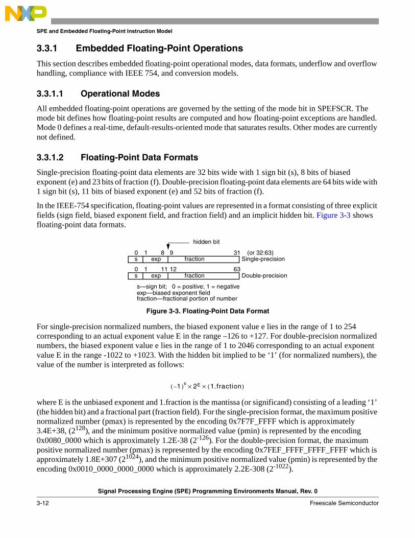
SPE and Embedded Floating-Point Instruction Model
Signal Processing Engine (SPE) Programming Environments Manual, Rev. 0
3-12 Freescale Semiconductor
3.3.1 Embedded Floating-Point Operations
This section describes embedded floating-point operational modes, data formats, underflow and overflow handling, compliance with IEEE 754, and conversion models.
3.3.1.1 Operational Modes
All embedded floating-point operations are governed by the setting of the mode bit in SPEFSCR. The mode bit defines how floating-point results are computed and how floating-point exceptions are handled. Mode 0 defines a real-time, default-results-oriented mode that saturates results. Other modes are currently not defined.
3.3.1.2 Floating-Point Data Formats
Single-precision floating-point data elements are 32 bits wide with 1 sign bit (s), 8 bits of biased exponent (e) and 23 bits of fraction (f). Double-precision floating-point data elements are 64 bits wide with 1 sign bit (s), 11 bits of biased exponent (e) and 52 bits of fraction (f).
In the IEEE-754 specification, floating-point values are represented in a format consisting of three explicit fields (sign field, biased exponent field, and fraction field) and an implicit hidden bit. Figure 3-3 shows floating-point data formats.
Figure 3-3. Floating-Point Data Format
For single-precision normalized numbers, the biased exponent value e lies in the range of 1 to 254 corresponding to an actual exponent value E in the range –126 to +127. For double-precision normalized numbers, the biased exponent value e lies in the range of 1 to 2046 corresponding to an actual exponent value E in the range -1022 to +1023. With the hidden bit implied to be ‘1’ (for normalized numbers), the value of the number is interpreted as follows:
where E is the unbiased exponent and 1.fraction is the mantissa (or significand) consisting of a leading ‘1’ (the hidden bit) and a fractional part (fraction field). For the single-precision format, the maximum positive normalized number (pmax) is represented by the encoding 0x7F7F_FFFF which is approximately 3.4E+38, (2128), and the minimum positive normalized value (pmin) is represented by the encoding 0x0080_0000 which is approximately 1.2E-38 (2-126). For the double-precision format, the maximum positive normalized number (pmax) is represented by the encoding 0x7FEF_FFFF_FFFF_FFFF which is approximately 1.8E+307 (21024), and the minimum positive normalized value (pmin) is represented by the encoding 0x0010_0000_0000_0000 which is approximately 2.2E-308 (2-1022).
fraction0
exp31 (or 32:63)8
s
s—sign bit; 0 = positive; 1 = negativeexp—biased exponent fieldfraction—fractional portion of number
1 9
fraction0
exp6311
s1 12
hidden bit
Double-precision
Single-precision
1–( )s 2E× 1.fraction( )×
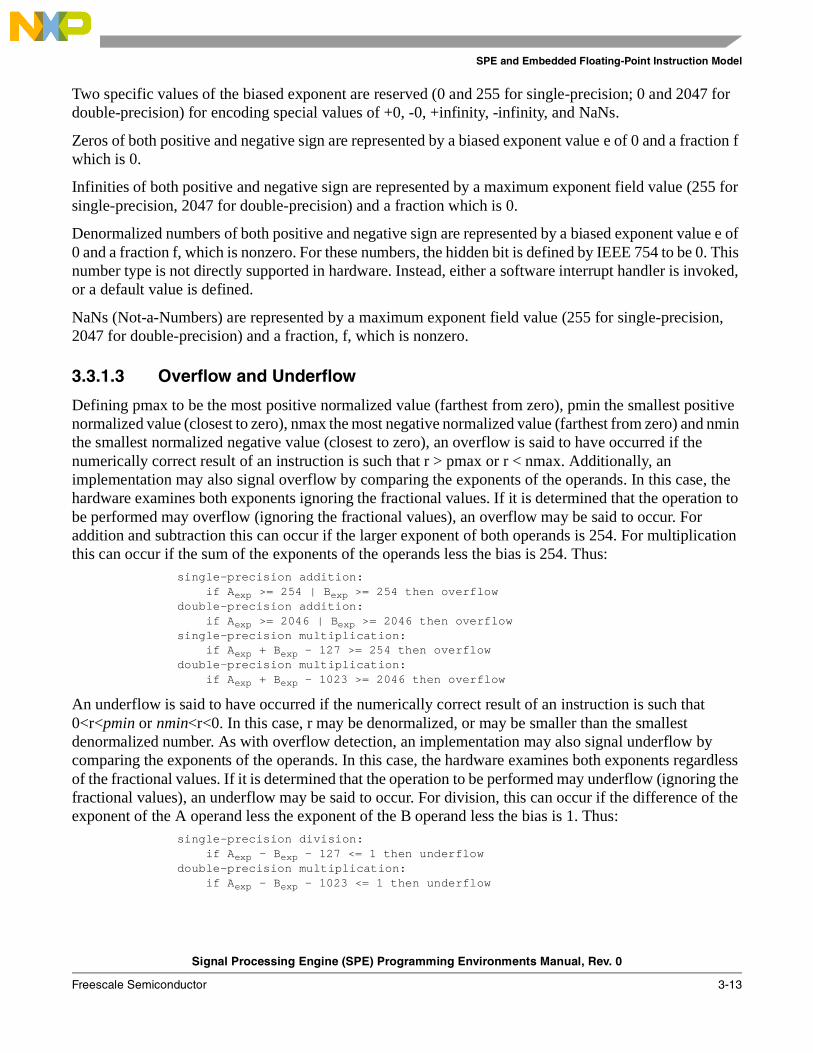
SPE and Embedded Floating-Point Instruction Model
Signal Processing Engine (SPE) Programming Environments Manual, Rev. 0
Freescale Semiconductor 3-13
Two specific values of the biased exponent are reserved (0 and 255 for single-precision; 0 and 2047 for double-precision) for encoding special values of +0, -0, +infinity, -infinity, and NaNs.
Zeros of both positive and negative sign are represented by a biased exponent value e of 0 and a fraction f which is 0.
Infinities of both positive and negative sign are represented by a maximum exponent field value (255 for single-precision, 2047 for double-precision) and a fraction which is 0.
Denormalized numbers of both positive and negative sign are represented by a biased exponent value e of 0 and a fraction f, which is nonzero. For these numbers, the hidden bit is defined by IEEE 754 to be 0. This number type is not directly supported in hardware. Instead, either a software interrupt handler is invoked, or a default value is defined.
NaNs (Not-a-Numbers) are represented by a maximum exponent field value (255 for single-precision, 2047 for double-precision) and a fraction, f, which is nonzero.
3.3.1.3 Overflow and Underflow
Defining pmax to be the most positive normalized value (farthest from zero), pmin the smallest positive normalized value (closest to zero), nmax the most negative normalized value (farthest from zero) and nmin the smallest normalized negative value (closest to zero), an overflow is said to have occurred if the numerically correct result of an instruction is such that r > pmax or r < nmax. Additionally, an implementation may also signal overflow by comparing the exponents of the operands. In this case, the hardware examines both exponents ignoring the fractional values. If it is determined that the operation to be performed may overflow (ignoring the fractional values), an overflow may be said to occur. For addition and subtraction this can occur if the larger exponent of both operands is 254. For multiplication this can occur if the sum of the exponents of the operands less the bias is 254. Thus:
single-precision addition:if Aexp >= 254 | Bexp >= 254 then overflow
double-precision addition:if Aexp >= 2046 | Bexp >= 2046 then overflow
single-precision multiplication:if Aexp + Bexp - 127 >= 254 then overflow
double-precision multiplication:if Aexp + Bexp - 1023 >= 2046 then overflow
An underflow is said to have occurred if the numerically correct result of an instruction is such that 0<r<pmin or nmin<r<0. In this case, r may be denormalized, or may be smaller than the smallest denormalized number. As with overflow detection, an implementation may also signal underflow by comparing the exponents of the operands. In this case, the hardware examines both exponents regardless of the fractional values. If it is determined that the operation to be performed may underflow (ignoring the fractional values), an underflow may be said to occur. For division, this can occur if the difference of the exponent of the A operand less the exponent of the B operand less the bias is 1. Thus:
single-precision division:if Aexp - Bexp - 127 <= 1 then underflow
double-precision multiplication:if Aexp - Bexp - 1023 <= 1 then underflow

SPE and Embedded Floating-Point Instruction Model
Signal Processing Engine (SPE) Programming Environments Manual, Rev. 0
3-14 Freescale Semiconductor
Embedded floating-point operations do not produce +Inf, –Inf, NaN, or a denormalized number. If the result of an instruction overflows and floating-point overflow exceptions are disabled (SPEFSCR[FOVFE] is cleared), pmax or nmax is generated as the result of that instruction depending on the sign of the result. If the result of an instruction underflows and floating-point underflow exceptions are disabled (SPEFSCR[FUNFE] is cleared), +0 or -0 is generated as the result of that instruction based upon the sign of the result.
3.3.1.4 IEEE Std 754™ Compliance
The embedded floating-point categories require a floating-point system as defined in IEEE 754 but may rely on software support in order to conform fully with the standard. Thus, whenever an input operand of the embedded floating-point instruction has data values that are +infinity, -infinity, alized, NaN, or when the result of an operation produces an overflow or an underflow, an embedded floating-point data interrupt may be taken and the interrupt handler is responsible for delivering IEEE 754–compliant behavior if desired.
When embedded floating-point invalid operation/input error exceptions are disabled (SPEFSCR[FINVE] = 0), default results are provided by the hardware when an infinity, denormalized, or NaN input is received, or for the operation 0/0. When embedded floating-point underflow exceptions are disabled (SPEFSCR[FUNFE] = 0) and the result of a floating-point operation underflows, a signed zero result is produced. The embedded floating-point round (inexact) exception is also signaled for this condition. When embedded floating-point overflow exceptions are disabled (SPEFSCR[FOVFE] = 0) and the result of a floating-point operation overflows, a pmax or nmax result is produced. The embedded floating-point round (inexact) exception is also signaled for this condition. An exception enable flag (SPEFSCR[FINXE]) is also provided for generating an embedded floating-point round interrupt when an inexact result is produced, to allow a software handler to conform to IEEE 754. An embedded floating-point divide by zero exception enable flag (SPEFSCR[FDBZE]) is provided for generating an embedded floating-point data interrupt when a divide by zero operation is attempted to allow a software handler to conform to IEEE 754. All of these exceptions may be disabled, and the hardware will then deliver an appropriate default result.
The sign of the result of an addition operation is the sign of the source operand having the larger absolute value. If both operands have the same sign, the sign of the result is the same as the sign of the operands. This includes subtraction which is addition with the negation of the sign of the second operand. The sign of the result of an addition operation with operands of differing signs for which the result is zero is positive except when rounding to negative infinity. Thus -0 + -0 = -0, and all other cases which result in a zero value give +0 unless the rounding mode is rounded to negative infinity.
NOTE (Programming)When exceptions are disabled and default results computed, operations having input values that are denormalized may provide different results on different implementations. An implementation may choose to use the denormalized value or a zero value for any computation. Thus a computational operation involving a denormalized value and a normal value may return different results depending on the implementation.
SPE and Embedded Floating-Point Instruction Model
Signal Processing Engine (SPE) Programming Environments Manual, Rev. 0
Freescale Semiconductor 3-15
3.3.1.5 Sticky Bit Handling for Exception Conditions
The SPEFSCR defines sticky bits for retaining information about exception conditions that are detected. These sticky bits (FINXS, FINVS, FDBZS, FUNFS, and FOVFS) can be used to help provide IEEE-754 compliance. The sticky bits represent the combined OR of all previous status bits produced from any embedded floating-point operation before the last time software zeroed the sticky bit. Only software can zero a sticky bit; hardware can only set sticky bits.
The SPEFSCR is described in Section 2.2.3, “Signal Processing Embedded Floating-Point Status and Control Register (SPEFSCR).” Interrupts are described in Chapter 4, “SPE/Embedded Floating-Point Interrupt Model.”
3.3.1.6 Implementation Options Summary
There are several options that may be chosen for a given implementation. This section summarizes implementation-dependent functionality and should be used with the processor core documentation to determine behavior of individual implementations.
• Floating-point instruction sets can be implemented independently of one another.
• Overflow and underflow conditions may be signaled by evaluating the exponent. If the evaluaton indicates an overflow or underflow could occur, the implementation may choose to signal an overflow or underflow. It is recommended that future implementations not use this estimation and that they signal overflow or underflow when they actually occur.
• If an operand for a calculation or conversion is denormalized, the implementation may choose to use a same-signed zero value in place of the denormalized operand.
• The rounding modes of +infinity and -infinity are not required to be handled by an implementation. If an implementation does not support ±infinity rounding modes and the rounding mode is set to be +infinity or -infinity, an embedded floating-point round interrupt occurs after every floating-point instruction for which rounding may occur, regardless of the value of FINXE, unless an embedded floating-point data interrupt also occurs and is taken.
• For absolute value, negate, and negative absolute value operations, an implementation may choose either to simply perform the sign bit operation, ignoring exceptions, or to compute the operation and handle exceptions and saturation where appropriate.
• SPEFSCR[FGH,FXH] are undefined on completion of a scalar floating-point operation. An implementation may choose to zero them or leave them unchanged.
• An implementation may choose to only implement sticky bit setting by hardware for FDBZS and FINXS, allowing software to manage the other sticky bits. It is recommended that all future implementations implement all sticky bit setting in hardware.
• For 64-bit implementations, the upper 32 bits of the destination register are undefined when the result of a scalar floating-point operation is a 32-bit result. It is recommended that future 64-bit implementations produce 64-bit results for the results of 64-bit convert-to-integer values.
3.3.1.7 Saturation, Shift, and Bit Reverse Models
For saturation, left shifts, and bit reversal, the pseudo-RTL is provided here to more accurately describe those functions referenced in the instruction pseudo-RTL.
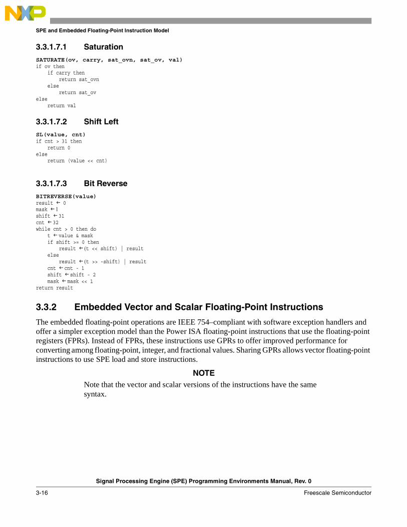
SPE and Embedded Floating-Point Instruction Model
Signal Processing Engine (SPE) Programming Environments Manual, Rev. 0
3-16 Freescale Semiconductor
3.3.1.7.1 Saturation
SATURATE(ov, carry, sat_ovn, sat_ov, val)if ov then
if carry thenreturn sat_ovn
elsereturn sat_ov
elsereturn val
3.3.1.7.2 Shift Left
SL(value, cnt)if cnt > 31 then
return 0else
return (value << cnt)
3.3.1.7.3 Bit Reverse
BITREVERSE(value)result 0mask 1shift 31cnt 32while cnt > 0 then do
t value & maskif shift >= 0 then
result (t << shift) | resultelse
result (t >> -shift) | resultcnt cnt - 1shift shift - 2mask mask << 1
return result
3.3.2 Embedded Vector and Scalar Floating-Point Instructions
The embedded floating-point operations are IEEE 754–compliant with software exception handlers and offer a simpler exception model than the Power ISA floating-point instructions that use the floating-point registers (FPRs). Instead of FPRs, these instructions use GPRs to offer improved performance for converting among floating-point, integer, and fractional values. Sharing GPRs allows vector floating-point instructions to use SPE load and store instructions.
NOTENote that the vector and scalar versions of the instructions have the same syntax.

SPE and Embedded Floating-Point Instruction Model
Signal Processing Engine (SPE) Programming Environments Manual, Rev. 0
Freescale Semiconductor 3-17
Table 3-6 lists the vector and scalar floating-point instructions.
Table 3-6. Vector and Scalar Floating-Point Instructions
InstructionSingle-Precision Double-
Precision Scalar
SyntaxScalar Vector
Convert Floating-Point Double- from Single-Precision — — efdcfs rD,rB
Convert Floating-Point from Signed Fraction efscfsf evfscfsf efdcfsf rD,rB
Convert Floating-Point from Signed Integer efscfsi evfscfsi efdcfsi rD,rB
Convert Floating-Point from Unsigned Fraction efscfuf evfscfuf efdcfuf rD,rB
Convert Floating-Point from Unsigned Integer efscfui evfscfui efdcfui rD,rB
Convert Floating-Point Single- from Double-Precision — — efscfd rD,rB
Convert Floating-Point to Signed Fraction efsctsf evfsctsf efdctsf rD,rB
Convert Floating-Point to Signed Integer efsctsi evfsctsi efdctsi rD,rB
Convert Floating-Point to Signed Integer with Round toward Zero efsctsiz evfsctsiz efdctsiz rD,rB
Convert Floating-Point to Unsigned Fraction efsctuf evfsctuf efdctuf rD,rB
Convert Floating-Point to Unsigned Integer efsctui evfsctui efdctui rD,rB
Convert Floating-Point to Unsigned Integer with Round toward Zero efsctuiz evfsctuiz efdctuiz rD,rB
Floating-Point Absolute Value efsabs 1
1 Exception detection for these instructions is implementation dependent. On some devices, infinities, NaNs, and denorms are always be treated as Norms. No exceptions are taken if SPEFSCR[FINVE] = 1.
evfsabs efdabs rD,rA
Floating-Point Add efsadd evfsadd efdadd rD,rA,rB
Floating-Point Compare Equal efscmpeq evfscmpeq efdcmpeq crD,rA,rB
Floating-Point Compare Greater Than efscmpgt evfscmpgt efdcmpgt crD,rA,rB
Floating-Point Compare Less Than efscmplt evfscmplt efdcmplt crD,rA,rB
Floating-Point Divide efsdiv evfsdiv efddiv rD,rA,rB
Floating-Point Multiply efsmul evfsmul efdmul rD,rA,rB
Floating-Point Negate efsneg 1 evfsneg efdneg rD,rA
Floating-Point Negative Absolute Value efsnabs 1 evfsnabs efdnabs rD,rA
Floating-Point Subtract efssub evfssub efdsub rD,rA,rB
Floating-Point Test Equal efststeq evfststeq efdtsteq crD,rA,rB
Floating-Point Test Greater Than efststgt evfststgt efdtstgt crD,rA,rB
Floating-Point Test Less Than efststlt evfststlt efdtstlt crD,rA,rB
SPE Double Word Load/Store Instructions
Vector Load Double Word into Double Word — evldd evldd rD,d(rA)
Vector Load Double Word into Double Word Indexed — evlddx evlddx rD,rA,rB
Vector Merge High — evmergehi evmergehi rD,rA,rB
Vector Merge Low — evmergelo evmergelo rD,rA,rB
Vector Store Double of Double — evstdd evstdd rS,d(rA)
Vector Store Double of Double Indexed — evstddx evstddx rS,rA,rB
Note: On some cores, floating-point operations that produce a result of zero may generate an incorrect sign.

SPE and Embedded Floating-Point Instruction Model
Signal Processing Engine (SPE) Programming Environments Manual, Rev. 0
3-18 Freescale Semiconductor
3.3.3 Load/Store Instructions
Embedded floating-point instructions use GPRs to hold and operate on floating-point values. Standard load and store instructions are used to move the data to and from memory. If vector single-precision or scalar double-precision embedded floating-point instructions are implemented on a 32-bit implementation, the GPRs are 64 bits wide. Because a 32-bit implementation contains no load or store instructions that operate on 64-bit data, the following SPE load/store instructions are used:
• evldd—Vector Load Doubleword into Doubleword
• evlddx—Vector Load Doubleword into Doubleword Indexed
• evstdd—Vector Store Doubleword of Doubleword
• evstddx—Vector Store Doubleword of Doubleword
• evmergehi—Vector Merge High
• evmergelo—Vector Merge Low
3.3.3.1 Floating-Point Conversion Models
Pseudo-RTL models for converting floating-point to and from non–floating-point is provided in Section 5.3.2, “Embedded Floating-Point Conversion Models,” as a group of functions called from the individual instruction pseudo-RTL descriptions, which are included in the instruction descriptions in Chapter 5, “Instruction Set.”
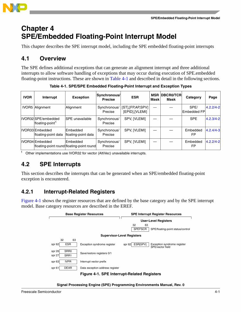
SPE/Embedded Floating-Point Interrupt Model
Signal Processing Engine (SPE) Programming Environments Manual, Rev. 0
Freescale Semiconductor 4-1
Chapter 4 SPE/Embedded Floating-Point Interrupt ModelThis chapter describes the SPE interrupt model, including the SPE embedded floating-point interrupts
4.1 OverviewThe SPE defines additional exceptions that can generate an alignment interrupt and three additional interrupts to allow software handling of exceptions that may occur during execution of SPE.embedded floating-point instructions. These are shown in Table 4-1 and described in detail in the following sections.
4.2 SPE InterruptsThis section describes the interrupts that can be generated when an SPE/embedded floating-point exception is encountered.
4.2.1 Interrupt-Related Registers
Figure 4-1 shows the register resources that are defined by the base category and by the SPE interrupt model. Base category resources are described in the EREF.
Table 4-1. SPE/SPE Embedded Floating-Point Interrupt and Exception Types
IVOR Interrupt ExceptionSynchronous/
PreciseESR
MSR Mask
DBCR0/TCRMask
Category Page
IVOR5 Alignment Alignment Synchronous/Precise
[ST],[FP,AP,SPV][EPID],[VLEMI]
— — SPE/Embedded FP
4.2.2/4-2
IVOR32 SPE/embedded floating-point1
1 Other implementations use IVOR32 for vector (AltiVec) unavailable interrupts.
SPE unavailable Synchronous/Precise
SPV, [VLEMI] — — SPE 4.2.3/4-2
IVOR33 Embedded floating-point data
Embedded floating-point data
Synchronous/Precise
SPV, [VLEMI] — — EmbeddedFP
4.2.4/4-3
IVOR34 Embedded floating-point round
Embedded floating-point round
Synchronous/Precise
SPV, [VLEMI] — — EmbeddedFP
4.2.2/4-2
Base Register Resources SPE Interrupt Register Resources
User-Level Registers32 63
SPEFSCR SPE/floating-point status/control
Supervisor-Level Registers32 63
spr 62 ESR Exception syndrome register spr 62 ESR[SPV] Exception syndrome register SPE/vector field
spr 26 SRR0Save/restore registers 0/1
spr 27 SRR1
spr 63 IVPR Interrupt vector prefix
spr 61 DEAR Data exception address register
Figure 4-1. SPE Interrupt-Related Registers

SPE/Embedded Floating-Point Interrupt Model
Signal Processing Engine (SPE) Programming Environments Manual, Rev. 0
4-2 Freescale Semiconductor
4.2.2 Alignment Interrupt
An SPE vector alignment exception occurs if the EA of any of the following instructions in not aligned to a 64-bit boundary: evldd, evlddx, evldw, evldwx, evldh, evldhx, evstdd, evstddx, evstdw, evstdwx, evstdh, or evstdhx. When an SPE vector alignment exception occurs, an alignment interrupt is taken and the processor suppresses execution of the instruction causing the exception. SRR0, SRR1, MSR, ESR, and DEAR are modified as follows:
• SRR0 is set to the EA of the instruction causing the interrupt.
• SRR1 is set to the contents of the MSR at the time of the interrupt.
• MSR bits CE, ME, and DE are unchanged. All other bits are cleared.
• ESR[SPV] is set. ESR[ST] is set if the instruction causing the interrupt is a store. All other ESR bits are cleared.
• DEAR is updated with the EA of the access that caused the exception. This is generally the EA of the instruction, except for some instructions that are misaligned or that reference multiple storage element.
Instruction execution resumes at address IVPR[0–47]||IVOR5[48–59]||0b0000.
4.2.3 SPE/Embedded Floating-Point Unavailable Interrupt
An SPE/embedded floating-point unavailable exception occurs on an attempt to execute any of the following instructions and MSR[SPV] is not set:
• SPE instruction (except brinc)
• An embedded scalar double-precision instruction
• A vector single-precision floating-point instructions
It is not used by embedded scalar single-precision floating-point instructions.
If this exception occurs, an SPE/embedded floating-point unavailable interrupt is taken and the processor suppresses execution of the instruction causing the exception. Registers are modified as follows:
The SRR0, SRR1, MSR, and ESR registers are modified as follows:
• SRR0 is set to the EA of the instruction causing the interrupt.
• SRR1 is set to the contents of the MSR at the time of the interrupt.
• MSR bits CE, ME, and DE are unchanged. All other bits are cleared.
• ESR bits SPV (and VLEMI if VLE is implemented and the instruction causing the interrupt resides in VLE storage) are set. All other ESR bits are cleared.
Instruction execution resumes at address IVPR[0–47]||IVOR32[48–59]||0b0000.
Interrupt Vector Offset Registers
spr 405 IVOR5 Alignment spr 528 IVOR32 SPE/Embedded FP
spr 529 IVOR33 Embedded FP data
spr 530 IVOR34 Embedded FP round
Figure 4-1. SPE Interrupt-Related Registers
SPE/Embedded Floating-Point Interrupt Model
Signal Processing Engine (SPE) Programming Environments Manual, Rev. 0
Freescale Semiconductor 4-3
NOTE (Software) Software should use this interrupt to determine if the application is using the upper 32 bits of the GPRs and thus is required to save and restore them on a context switch.
4.2.4 SPE Embedded Floating-Point Interrupts
The following sections describe SPE embedded floating-point interrupts:
• Section 4.2.4.1, “Embedded Floating-Point Data Interrupt”
• Section 4.2.4.2, “Embedded Floating-Point Round Interrupt”
4.2.4.1 Embedded Floating-Point Data Interrupt
The embedded floating-point data interrupt vector is used for enabled floating-point invalid operation/input error, underflow, overflow, and divide-by-zero exceptions (collectively called floating-point data exceptions). When one of these enabled exceptions occurs, the processor suppresses execution of the instruction causing the exception. The SRR0, SRR1, MSR, ESR, and SPEFSCR are modified as follows:
• SRR0 is set to the EA of the instruction causing the interrupt.
• SRR1 is set to the contents of the MSR at the time of the interrupt.
• MSR bits CE, ME, and DE are unchanged. All other bits are cleared.
• ESR[SPV] is set. All other ESR bits are cleared.
• One or more SPEFSCR status bits are set to indicate the type of exception. The affected bits are FINVH, FINV, FDBZH, FDBZ, FOVFH, FOVF, FUNFH, and FUNF. SPEFSCR[FG,FGH, FX, FXH] are cleared.
Instruction execution resumes at address IVPR[0–47]||IVOR33[48–59]||0b0000.
4.2.4.2 Embedded Floating-Point Round Interrupt
The embedded floating-point round interrupt occurs if no other floating-point data interrupt is taken and one of the following conditions is met:
• SPEFSCR[FINXE] is set and the unrounded result of an operation is not exact
• SPEFSCR[FINXE] is set, an overflow occurs, and overflow exceptions are disabled (FOVF or FOVFH set with FOVFE cleared)
• An underflow occurs and underflow exceptions are disabled (FUNF set with FUNFE cleared)
The embedded floating-point round interrupt does not occur if an enabled embedded floating-point data interrupt occurs.
SPE/Embedded Floating-Point Interrupt Model
Signal Processing Engine (SPE) Programming Environments Manual, Rev. 0
4-4 Freescale Semiconductor
NOTE (Programming)If an implementation does not support ±infinity rounding modes and the rounding mode is set to be +infinity or -infinity, an embedded floating-point round interrupt occurs after every embedded floating-point instruction for which rounding might occur regardless of the FINXE value, if no higher priority exception exists.
When an embedded floating-point round interrupt occurs, the unrounded (truncated) result of an inexact high or low element is placed in the target register. If only a single element is inexact, the other exact element is updated with the correctly rounded result, and the FG and FX bits corresponding to the other exact element are be 0.
FG (FGH) and FX (FXH) are provided so an interrupt handler can round the result as it desires. FG (FGH) is the value of the bit immediately to the right of the lsb of the destination format mantissa from the infinitely precise intermediate calculation before rounding. FX (FXH) is the value of the OR of all bits to the right of the FG (FGH) of the destination format mantissa from the infinitely precise intermediate calculation before rounding.
The SRR0, SRR1, MSR, ESR, and SPEFSCR are modified as follows:
• SRR0 is set to the EA of the instruction following the instruction causing the interrupt.
• SRR1 is set to the contents of the MSR at the time of the interrupt.
• MSR bits CE, ME, and DE are unchanged. All other bits are cleared.
• ESR[SPV] is set. All other ESR bits are cleared.
• SPEFSCR[FGH,FG,FXH,FX] are set appropriately. SPEFSCR[FINXS] is set.
Instruction execution resumes at address IVPR[0–47]||IVOR34[48–59]||0b0000.
4.3 Interrupt PrioritiesThe priority order among the SPE and embedded floating-point interrupts is as follows:
1. SPE/embedded floating-point unavailable interrupt
2. SPE vector alignment interrupt
3. Embedded floating-point data interrupt
4. Embedded floating-point round interrupt
The EREF describes how these interrupts are prioritized among the other Power ISA interrupts. Only one of the above types of synchronous interrupts may have an existing exception generating it at any given time. This is guaranteed by the exception priority mechanism and the requirements of the sequential execution model.
4.4 Exception ConditionsThe following sections describe the exception conditions that can generate the interrupts described in Section 4.2, “SPE Interrupts.” Enable and status bits associated with these programming exceptions can
SPE/Embedded Floating-Point Interrupt Model
Signal Processing Engine (SPE) Programming Environments Manual, Rev. 0
Freescale Semiconductor 4-5
be found in the SPEFSCR, described in Section 2.2.3, “Signal Processing Embedded Floating-Point Status and Control Register (SPEFSCR).”
4.4.1 Floating-Point Exception Conditions
This section describes the conditions that generate exceptions that, depending on how the processor is configured, may generate an interrupt.
4.4.1.1 Denormalized Values on Input
Any denormalized value used as an operand may be truncated by the implementation to a properly signed zero value.
4.4.1.2 Embedded Floating-Point Overflow and Underflow
Defining pmax to be the most positive normalized value (farthest from zero), pmin the smallest positive normalized value (closest to zero), nmax the most negative normalized value (farthest from zero) and nmin the smallest normalized negative value (closest to zero), an overflow is said to have occurred if the numerically correct result (r) of an instruction is such that r>pmax or r<nmax. An underflow is said to have occurred if the numerically correct result of an instruction is such that 0<r<pmin or nmin<r<0. In this case, r may be denormalized, or may be smaller than the smallest denormalized number.
The embedded floating-point categories do not produce +infinity, -infinity, NaN, or denormalized numbers. If the result of an instruction overflows and embedded floating-point overflow exceptions are disabled (SPEFSCR[FOVFE]=0), pmax or nmax is generated as the result of that instruction depending upon the sign of the result. If the result of an instruction underflows and embedded floating-point underflow exceptions are disabled (SPEFSCR[FUNFE]=0), +0 or -0 is generated as the result of that instruction based upon the sign of the result.
If an overflow occurs, SPEFSCR[FOVF FOVFH] are set appropriately, or if an underflow occurs, SPEFSCR[FUNF FUNFH] are set appropriately. If either embedded floating-point underflow or embedded floating-point overflow exceptions are enabled and a corresponding status bit is 1, an embedded floating-point data interrupt is taken and the destination register is not updated.
NOTE (Programming)On some implementations, operations that result in overflow or underflow are likely to take significantly longer than those that do not. For example, these operations may cause a system error handler to be invoked; on such implementations, the system error handler updates overflow bits appropriately.
4.4.1.3 Embedded Floating-Point Invalid Operation/Input Errors
Embedded floating-point invalid operation/input errors occur when an operand to an operation contains an invalid input value. If any of the input values are infinity, denorm, or NaN, or for an embedded floating-point divide instruction both operands are +/-0, SPEFSCR[FINV FINVH] are set appropriately,
SPE/Embedded Floating-Point Interrupt Model
Signal Processing Engine (SPE) Programming Environments Manual, Rev. 0
4-6 Freescale Semiconductor
and SPEFSCR[FGH FXH FG FX] are cleared appropriately. If SPEFSCR[FINVE]=1, an embedded floating-point data interrupt is taken and the destination register is not updated.
4.4.1.4 Embedded Floating-Point Round (Inexact)
If any result element of an embedded floating-point instruction is inexact, or overflows but embedded floating-point overflow exceptions are disabled, or underflows but embedded floating-point underflow exceptions are disabled, and no higher priority interrupt occurs, SPEFSCR[FINXS] is set. If the embedded floating-point round (inexact) exception is enabled, an embedded floating-point round interrupt occurs. In this case, the destination register is updated with the truncated results. SPEFSCR[FGH FXH FG FX] are properly updated to allow rounding to be performed in the interrupt handler.
SPEFSCR[FG FX] (SPEFSCR[FGH FXH]) are cleared if an embedded floating-point data interrupt is taken due to overflow or underflow, or if an embedded floating-point invalid operation/input error is signaled for the low (high) element (regardless of SPEFSCR[FINVE]).
4.4.1.5 Embedded Floating-Point Divide by Zero
If an embedded floating-point divide instruction executes and an embedded floating-point invalid operation/input error does not occur and the instruction is executed with a +/-0 divisor value and a finite normalized nonzero dividend value, an embedded floating-point divide by zero exception occurs and SPEFSCR[FDBZ FDBZH] are set appropriately. If embedded floating-point divide by zero exceptions are enabled, an embedded floating-point data interrupt is then taken and the destination register is not updated.
4.4.1.6 Default Results
Default results are generated when an embedded floating-point invalid operation/input error, embedded floating-point overflow, embedded floating-point underflow, or embedded floating-point divide by zero occurs on an embedded floating-point operation. Default results provide a normalized value as a result of the operation. In general, denormalized results and underflows are cleared and overflows are saturated to the maximum representable number.
Default results for each operation are described in Section 5.3.4, “Embedded Floating-Point Results.”

Signal Processing Engine (SPE) Programming Environments Manual, Rev. 0
Freescale Semiconductor 5-1
Chapter 5 Instruction SetThis chapter describes the SPE instructions and the embedded floating-point instructions, which are as follows:
• Single-precision scalar floating-point (SPE FS)
• Single-precision vector floating-point (SPE FV)
• Double-precision scalar floating-point (SPE FD)
5.1 NotationThe definitions and notation listed in Table 5-1 are used throughout this chapter in the instruction descriptions.
Table 5-1. Notation Conventions
Symbol Meaning
Xp Bit p of register/field X
Xfield The bits composing a defined field of X. For example, Xsign, Xexp, and Xfrac represent the sign, exponent, and fractional value of a floating-point number X
Xp:q Bits p through q of register/field X
Xp q ... Bits p, q,... of register/field X
¬X The one’s complement of the contents of X
Field i Bits 4× i through 4× i+3 of a register
|| Describes the concatenation of two values. For example, 010 || 111 is the same as 010111.
xn x raised to the nth power
nx The replication of x, n times (i.e., x concatenated to itself n–1 times). n0 and n1 are special cases: n0 means a field of n bits with each bit equal to 0. Thus 50 is equivalent to 0b0_0000.n1 means a field of n bits with each bit equal to 1. Thus 51 is equivalent to 0b1_1111.
/, //, ///, A reserved field in an instruction or in a register.
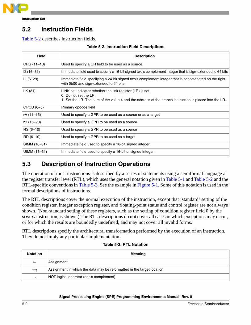
Instruction Set
Signal Processing Engine (SPE) Programming Environments Manual, Rev. 0
5-2 Freescale Semiconductor
5.2 Instruction FieldsTable 5-2 describes instruction fields.
5.3 Description of Instruction OperationsThe operation of most instructions is described by a series of statements using a semiformal language at the register transfer level (RTL), which uses the general notation given in Table 5-1 and Table 5-2 and the RTL-specific conventions in Table 5-3. See the example in Figure 5-1. Some of this notation is used in the formal descriptions of instructions.
The RTL descriptions cover the normal execution of the instruction, except that ‘standard’ setting of the condition register, integer exception register, and floating-point status and control register are not always shown. (Non-standard setting of these registers, such as the setting of condition register field 0 by the stwcx. instruction, is shown.) The RTL descriptions do not cover all cases in which exceptions may occur, or for which the results are boundedly undefined, and may not cover all invalid forms.
RTL descriptions specify the architectural transformation performed by the execution of an instruction. They do not imply any particular implementation.
Table 5-2. Instruction Field Descriptions
Field Description
CRS (11–13) Used to specify a CR field to be used as a source
D (16–31) Immediate field used to specify a 16-bit signed two’s complement integer that is sign-extended to 64 bits
LI (6–29) Immediate field specifying a 24-bit signed two’s complement integer that is concatenated on the right with 0b00 and sign-extended to 64 bits
LK (31) LINK bit. Indicates whether the link register (LR) is set. 0 Do not set the LR.1 Set the LR. The sum of the value 4 and the address of the branch instruction is placed into the LR.
OPCD (0–5) Primary opcode field
rA (11–15) Used to specify a GPR to be used as a source or as a target
rB (16–20) Used to specify a GPR to be used as a source
RS (6–10) Used to specify a GPR to be used as a source
RD (6–10) Used to specify a GPR to be used as a target
SIMM (16–31) Immediate field used to specify a 16-bit signed integer
UIMM (16–31) Immediate field used to specify a 16-bit unsigned integer
Table 5-3. RTL Notation
Notation Meaning
← Assignment
←f Assignment in which the data may be reformatted in the target location
¬ NOT logical operator (one’s complement)
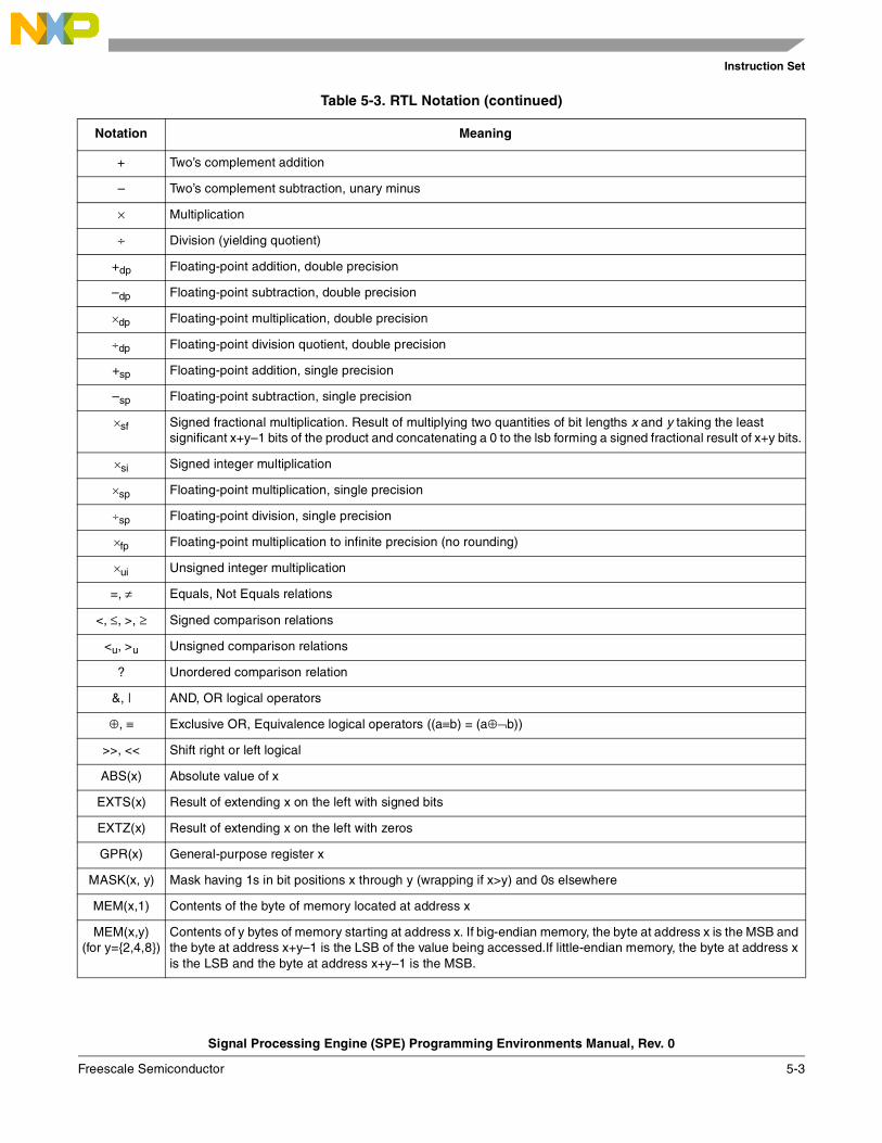
Instruction Set
Signal Processing Engine (SPE) Programming Environments Manual, Rev. 0
Freescale Semiconductor 5-3
+ Two’s complement addition
– Two’s complement subtraction, unary minus
× Multiplication
÷ Division (yielding quotient)
+dp Floating-point addition, double precision
–dp Floating-point subtraction, double precision
×dp Floating-point multiplication, double precision
÷dp Floating-point division quotient, double precision
+sp Floating-point addition, single precision
–sp Floating-point subtraction, single precision
×sf Signed fractional multiplication. Result of multiplying two quantities of bit lengths x and y taking the least significant x+y–1 bits of the product and concatenating a 0 to the lsb forming a signed fractional result of x+y bits.
×si Signed integer multiplication
×sp Floating-point multiplication, single precision
÷sp Floating-point division, single precision
×fp Floating-point multiplication to infinite precision (no rounding)
×ui Unsigned integer multiplication
=, ≠ Equals, Not Equals relations
<, ≤, >, ≥ Signed comparison relations
<u, >u Unsigned comparison relations
? Unordered comparison relation
&, | AND, OR logical operators
⊕, ≡ Exclusive OR, Equivalence logical operators ((a≡b) = (a⊕¬b))
>>, << Shift right or left logical
ABS(x) Absolute value of x
EXTS(x) Result of extending x on the left with signed bits
EXTZ(x) Result of extending x on the left with zeros
GPR(x) General-purpose register x
MASK(x, y) Mask having 1s in bit positions x through y (wrapping if x>y) and 0s elsewhere
MEM(x,1) Contents of the byte of memory located at address x
MEM(x,y)(for y={2,4,8})
Contents of y bytes of memory starting at address x. If big-endian memory, the byte at address x is the MSB and the byte at address x+y–1 is the LSB of the value being accessed.If little-endian memory, the byte at address x is the LSB and the byte at address x+y–1 is the MSB.
Table 5-3. RTL Notation (continued)
Notation Meaning
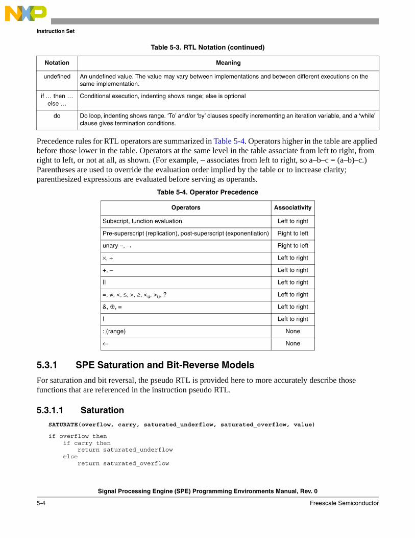
Instruction Set
Signal Processing Engine (SPE) Programming Environments Manual, Rev. 0
5-4 Freescale Semiconductor
Precedence rules for RTL operators are summarized in Table 5-4. Operators higher in the table are applied before those lower in the table. Operators at the same level in the table associate from left to right, from right to left, or not at all, as shown. (For example, – associates from left to right, so a–b–c = (a–b)–c.) Parentheses are used to override the evaluation order implied by the table or to increase clarity; parenthesized expressions are evaluated before serving as operands.
5.3.1 SPE Saturation and Bit-Reverse Models
For saturation and bit reversal, the pseudo RTL is provided here to more accurately describe those functions that are referenced in the instruction pseudo RTL.
5.3.1.1 Saturation
SATURATE(overflow, carry, saturated_underflow, saturated_overflow, value)
if overflow thenif carry then
return saturated_underflowelse
return saturated_overflow
undefined An undefined value. The value may vary between implementations and between different executions on the same implementation.
if … then … else …
Conditional execution, indenting shows range; else is optional
do Do loop, indenting shows range. ‘To’ and/or ‘by’ clauses specify incrementing an iteration variable, and a ‘while’ clause gives termination conditions.
Table 5-4. Operator Precedence
Operators Associativity
Subscript, function evaluation Left to right
Pre-superscript (replication), post-superscript (exponentiation) Right to left
unary –, ¬ Right to left
×, ÷ Left to right
+, – Left to right
|| Left to right
=, ≠, <, ≤, >, ≥, <u, >u, ? Left to right
&, ⊕, ≡ Left to right
| Left to right
: (range) None
← None
Table 5-3. RTL Notation (continued)
Notation Meaning
Instruction Set
Signal Processing Engine (SPE) Programming Environments Manual, Rev. 0
Freescale Semiconductor 5-5
elsereturn value
5.3.1.2 Bit ReverseBITREVERSE(value)
result ← 0mask ← 1shift ← 31cnt ← 32while cnt > 0 then do
t ← data & maskif shift >= 0 then
result ← (t << shift) | resultelse
result ← (t >> -shift) | resultcnt ← cnt - 1shift ← shift - 2mask ← mask << 1
return result
5.3.2 Embedded Floating-Point Conversion Models
The embedded floating-point instructions defined by the signal processing engine (SPE) contain floating-point conversion to and from integer and fractional type instructions. The floating-point to-and-from non–floating-point conversion model pseudo-RTL is provided in Table 5-5 as a group of functions that is called from the individual instruction pseudo-RTL descriptions.
Table 5-5. Conversion Models
Function Name Reference
Common Functions
Round a 32-bit value Round32(fp,guard,sticky) 5.3.2.1.3/5-6
Round a 64-bit value Round64(fp,guard,sticky) 5.3.2.1.4/5-7
Signal floating-point error SignalFPError 5.3.2.1.2/5-6
Is a 32-bit value a NaN or infinity? Isa32NaNorinfinity(fp) 5.3.2.1.1/5-6
Floating-Point Conversions
Convert from single-precision floating-point to integer word with saturation
CnvtFP32ToI32Sat(fp,signed,upper_lower,round,fractional) 5.3.2.2/5-7
Convert from double-precision floating-point to integer word with saturation
CnvtFP64ToI32Sat(fp,signed,round,fractional) 5.3.2.3/5-9
Convert from double-precision floating-point to integer double word with saturation
CnvtFP64ToI64Sat(fp,signed,round) 5.3.2.4/5-10
Convert to single-precision floating-point from integer word with saturation
CnvtI32ToFP32Sat(v,signed,upper_lower,fractional) 5.3.2.5/5-11
Convert to double-precision floating-point from integer double word with saturation
CnvtI64ToFP64Sat(v,signed) 5.3.2.7/5-13
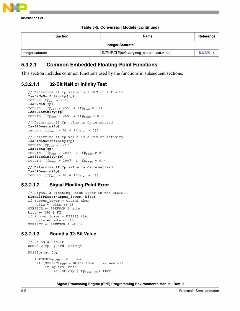
Instruction Set
Signal Processing Engine (SPE) Programming Environments Manual, Rev. 0
5-6 Freescale Semiconductor
5.3.2.1 Common Embedded Floating-Point Functions
This section includes common functions used by the functions in subsequent sections.
5.3.2.1.1 32-Bit NaN or Infinity Test
// Determine if fp value is a NaN or infinityIsa32NaNorInfinity(fp)return (fpexp = 255)Isa32NaN(fp)return ((fpexp = 255) & (fpfrac ≠ 0))Isa32Infinity(fp)return ((fpexp = 255) & (fpfrac = 0))
// Determine if fp value is denormalizedIsa32Denorm(fp)return ((fpexp = 0) & (fpfrac ≠ 0))
// Determine if fp value is a NaN or InfinityIsa64NaNorInfinity(fp)return (fpexp = 2047)Isa64NaN(fp)return ((fpexp = 2047) & (fpfrac ≠ 0))Isa64Infinity(fp)return ((fpexp = 2047) & (fpfrac = 0))
// Determine if fp value is denormalizedIsa64Denorm(fp)return ((fpexp = 0) & (fpfrac ≠ 0))
5.3.2.1.2 Signal Floating-Point Error
// Signal a Floating-Point Error in the SPEFSCRSignalFPError(upper_lower, bits)if (upper_lower = UPPER) then
bits ← bits << 15SPEFSCR ← SPEFSCR | bitsbits ← (FG | FX)if (upper_lower = UPPER) then
bits ← bits << 15SPEFSCR ← SPEFSCR & ¬bits
5.3.2.1.3 Round a 32-Bit Value
// Round a resultRound32(fp, guard, sticky)
FP32format fp;
if (SPEFSCRFINXE = 0) thenif (SPEFSCRFRMC = 0b00) then // nearest
if (guard) thenif (sticky | fpfrac[22]) then
Integer Saturate
Integer saturate SATURATE(ovf,carry,neg_sat,pos_sat,value) 5.3.3/5-14
Table 5-5. Conversion Models (continued)
Function Name Reference
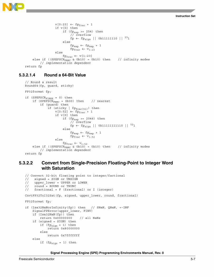
Instruction Set
Signal Processing Engine (SPE) Programming Environments Manual, Rev. 0
Freescale Semiconductor 5-7
v[0:23] ← fpfrac + 1if v[0] then
if (fpexp >= 254) then// overflowfp ← fpsign || 0b11111110 ||
231else
fpexp ← fpexp + 1fpfrac ← v1:23
elsefpfrac ← v[1:23]
else if ((SPEFSCRFRMC & 0b10) = 0b10) then // infinity modes// implementation dependent
return fp
5.3.2.1.4 Round a 64-Bit Value
// Round a resultRound64(fp, guard, sticky)
FP32format fp;
if (SPEFSCRFINXE = 0) thenif (SPEFSCRFRMC = 0b00) then // nearest
if (guard) thenif (sticky | fpfrac[51]) then
v[0:52] ← fpfrac + 1if v[0] then
if (fpexp >= 2046) then// overflowfp ← fpsign || 0b11111111110 ||
521else
fpexp ← fpexp + 1fpfrac ← v1:52
elsefpfrac ← v1:52
else if ((SPEFSCRFRMC & 0b10) = 0b10) then // infinity modes// implementation dependent
return fp
5.3.2.2 Convert from Single-Precision Floating-Point to Integer Word with Saturation
// Convert 32-bit floating point to integer/factional// signed = SIGN or UNSIGN// upper_lower = UPPER or LOWER// round = ROUND or TRUNC// fractional = F (fractional) or I (integer)
CnvtFP32ToI32Sat(fp, signed, upper_lower, round, fractional)
FP32format fp;
if (Isa32NaNorInfinity(fp)) then // SNaN, QNaN, +-INFSignalFPError(upper_lower, FINV)if (Isa32NaN(fp)) then
return 0x00000000 // all NaNsif (signed = SIGN) then
if (fpsign = 1) thenreturn 0x80000000
elsereturn 0x7fffffff
elseif (fpsign = 1) then
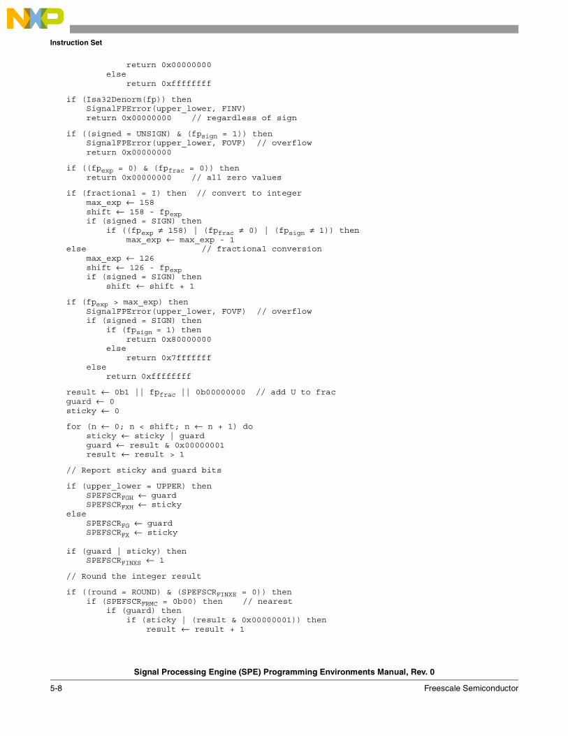
Instruction Set
Signal Processing Engine (SPE) Programming Environments Manual, Rev. 0
5-8 Freescale Semiconductor
return 0x00000000else
return 0xffffffff
if (Isa32Denorm(fp)) thenSignalFPError(upper_lower, FINV)return 0x00000000 // regardless of sign
if ((signed = UNSIGN) & (fpsign = 1)) thenSignalFPError(upper_lower, FOVF) // overflowreturn 0x00000000
if ((fpexp = 0) & (fpfrac = 0)) thenreturn 0x00000000 // all zero values
if (fractional = I) then // convert to integermax_exp ← 158shift ← 158 - fpexpif (signed = SIGN) then
if ((fpexp ≠ 158) | (fpfrac ≠ 0) | (fpsign ≠ 1)) thenmax_exp ← max_exp - 1
else // fractional conversionmax_exp ← 126shift ← 126 - fpexpif (signed = SIGN) then
shift ← shift + 1
if (fpexp > max_exp) thenSignalFPError(upper_lower, FOVF) // overflowif (signed = SIGN) then
if (fpsign = 1) thenreturn 0x80000000
elsereturn 0x7fffffff
elsereturn 0xffffffff
result ← 0b1 || fpfrac || 0b00000000 // add U to fracguard ← 0sticky ← 0
for (n ← 0; n < shift; n ← n + 1) dosticky ← sticky | guardguard ← result & 0x00000001result ← result > 1
// Report sticky and guard bits
if (upper_lower = UPPER) thenSPEFSCRFGH ← guardSPEFSCRFXH ← sticky
elseSPEFSCRFG ← guardSPEFSCRFX ← sticky
if (guard | sticky) thenSPEFSCRFINXS ← 1
// Round the integer result
if ((round = ROUND) & (SPEFSCRFINXE = 0)) thenif (SPEFSCRFRMC = 0b00) then // nearest
if (guard) thenif (sticky | (result & 0x00000001)) then
result ← result + 1
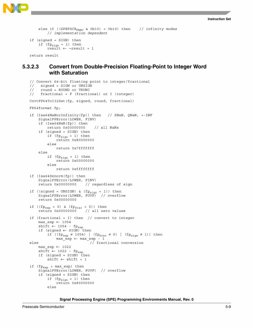
Instruction Set
Signal Processing Engine (SPE) Programming Environments Manual, Rev. 0
Freescale Semiconductor 5-9
else if ((SPEFSCRFRMC & 0b10) = 0b10) then // infinity modes// implementation dependent
if (signed = SIGN) thenif (fpsign = 1) then
result ← ¬result + 1
return result
5.3.2.3 Convert from Double-Precision Floating-Point to Integer Word with Saturation
// Convert 64-bit floating point to integer/fractional// signed = SIGN or UNSIGN// round = ROUND or TRUNC// fractional = F (fractional) or I (integer)
CnvtFP64ToI32Sat(fp, signed, round, fractional)
FP64format fp;
if (Isa64NaNorInfinity(fp)) then // SNaN, QNaN, +-INFSignalFPError(LOWER, FINV)if (Isa64NaN(fp)) then
return 0x00000000 // all NaNsif (signed = SIGN) then
if (fpsign = 1) thenreturn 0x80000000
elsereturn 0x7fffffff
elseif (fpsign = 1) then
return 0x00000000else
return 0xffffffff
if (Isa64Denorm(fp)) thenSignalFPError(LOWER, FINV)return 0x00000000 // regardless of sign
if ((signed = UNSIGN) & (fpsign = 1)) thenSignalFPError(LOWER, FOVF) // overflowreturn 0x00000000
if ((fpexp = 0) & (fpfrac = 0)) thenreturn 0x00000000 // all zero values
if (fractional = I) then // convert to integermax_exp ← 1054shift ← 1054 - fpexpif (signed ← SIGN) then
if ((fpexp ≠ 1054) | (fpfrac ≠ 0) | (fpsign ≠ 1)) thenmax_exp ← max_exp - 1
else // fractional conversionmax_exp ← 1022shift ← 1022 - fpexpif (signed = SIGN) then
shift ← shift + 1
if (fpexp > max_exp) thenSignalFPError(LOWER, FOVF) // overflowif (signed = SIGN) then
if (fpsign = 1) thenreturn 0x80000000
else
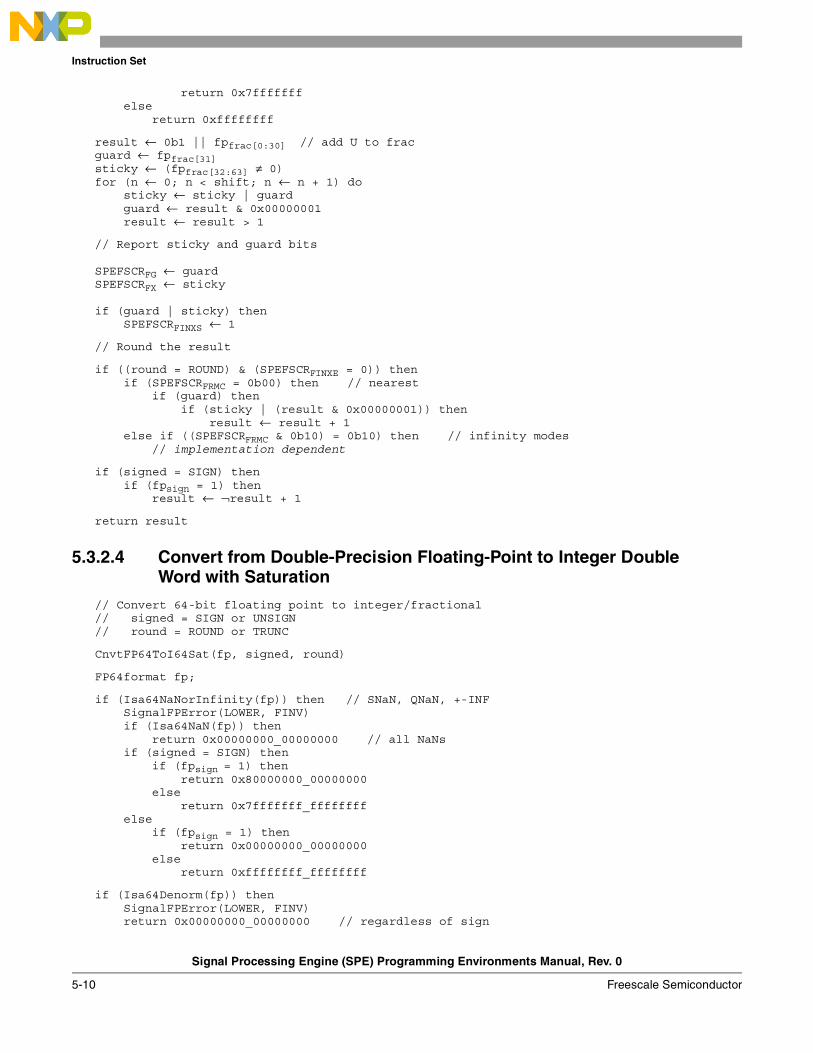
Instruction Set
Signal Processing Engine (SPE) Programming Environments Manual, Rev. 0
5-10 Freescale Semiconductor
return 0x7fffffffelse
return 0xffffffff
result ← 0b1 || fpfrac[0:30] // add U to fracguard ← fpfrac[31]sticky ← (fpfrac[32:63] ≠ 0)for (n ← 0; n < shift; n ← n + 1) do
sticky ← sticky | guardguard ← result & 0x00000001result ← result > 1
// Report sticky and guard bits
SPEFSCRFG ← guardSPEFSCRFX ← sticky
if (guard | sticky) thenSPEFSCRFINXS ← 1
// Round the result
if ((round = ROUND) & (SPEFSCRFINXE = 0)) thenif (SPEFSCRFRMC = 0b00) then // nearest
if (guard) thenif (sticky | (result & 0x00000001)) then
result ← result + 1else if ((SPEFSCRFRMC & 0b10) = 0b10) then // infinity modes
// implementation dependent
if (signed = SIGN) thenif (fpsign = 1) then
result ← ¬result + 1
return result
5.3.2.4 Convert from Double-Precision Floating-Point to Integer Double Word with Saturation
// Convert 64-bit floating point to integer/fractional// signed = SIGN or UNSIGN// round = ROUND or TRUNC
CnvtFP64ToI64Sat(fp, signed, round)
FP64format fp;
if (Isa64NaNorInfinity(fp)) then // SNaN, QNaN, +-INFSignalFPError(LOWER, FINV)if (Isa64NaN(fp)) then
return 0x00000000_00000000 // all NaNsif (signed = SIGN) then
if (fpsign = 1) thenreturn 0x80000000_00000000
elsereturn 0x7fffffff_ffffffff
elseif (fpsign = 1) then
return 0x00000000_00000000else
return 0xffffffff_ffffffff
if (Isa64Denorm(fp)) thenSignalFPError(LOWER, FINV)return 0x00000000_00000000 // regardless of sign
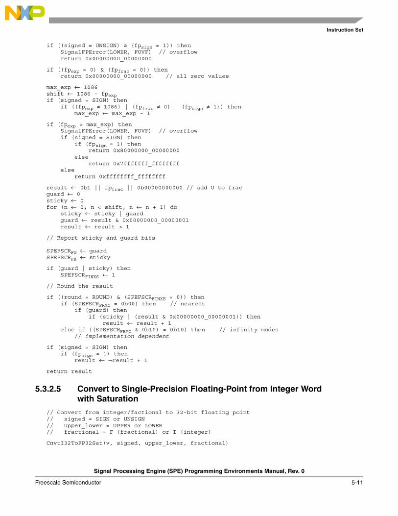
Instruction Set
Signal Processing Engine (SPE) Programming Environments Manual, Rev. 0
Freescale Semiconductor 5-11
if ((signed = UNSIGN) & (fpsign = 1)) thenSignalFPError(LOWER, FOVF) // overflowreturn 0x00000000_00000000
if ((fpexp = 0) & (fpfrac = 0)) thenreturn 0x00000000_00000000 // all zero values
max_exp ← 1086shift ← 1086 - fpexpif (signed = SIGN) then
if ((fpexp ≠ 1086) | (fpfrac ≠ 0) | (fpsign ≠ 1)) thenmax_exp ← max_exp - 1
if (fpexp > max_exp) thenSignalFPError(LOWER, FOVF) // overflowif (signed = SIGN) then
if (fpsign = 1) thenreturn 0x80000000_00000000
elsereturn 0x7fffffff_ffffffff
elsereturn 0xffffffff_ffffffff
result ← 0b1 || fpfrac || 0b00000000000 // add U to fracguard ← 0sticky ← 0for (n ← 0; n < shift; n ← n + 1) do
sticky ← sticky | guardguard ← result & 0x00000000_00000001result ← result > 1
// Report sticky and guard bits
SPEFSCRFG ← guardSPEFSCRFX ← sticky
if (guard | sticky) thenSPEFSCRFINXS ← 1
// Round the result
if ((round = ROUND) & (SPEFSCRFINXE = 0)) thenif (SPEFSCRFRMC = 0b00) then // nearest
if (guard) thenif (sticky | (result & 0x00000000_00000001)) then
result ← result + 1else if ((SPEFSCRFRMC & 0b10) = 0b10) then // infinity modes
// implementation dependent
if (signed = SIGN) thenif (fpsign = 1) then
result ← ¬result + 1
return result
5.3.2.5 Convert to Single-Precision Floating-Point from Integer Word with Saturation
// Convert from integer/factional to 32-bit floating point// signed = SIGN or UNSIGN// upper_lower = UPPER or LOWER// fractional = F (fractional) or I (integer)
CnvtI32ToFP32Sat(v, signed, upper_lower, fractional)
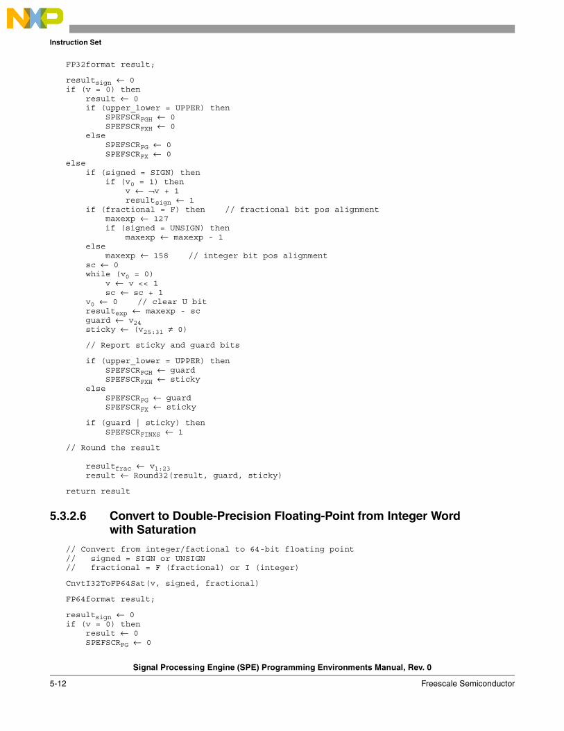
Instruction Set
Signal Processing Engine (SPE) Programming Environments Manual, Rev. 0
5-12 Freescale Semiconductor
FP32format result;
resultsign ← 0if (v = 0) then
result ← 0if (upper_lower = UPPER) then
SPEFSCRFGH ← 0SPEFSCRFXH ← 0
elseSPEFSCRFG ← 0SPEFSCRFX ← 0
elseif (signed = SIGN) then
if (v0 = 1) thenv ← ¬v + 1resultsign ← 1
if (fractional = F) then // fractional bit pos alignmentmaxexp ← 127if (signed = UNSIGN) then
maxexp ← maxexp - 1else
maxexp ← 158 // integer bit pos alignmentsc ← 0while (v0 = 0)
v ← v << 1sc ← sc + 1
v0 ← 0 // clear U bitresultexp ← maxexp - scguard ← v24sticky ← (v25:31 ≠ 0)
// Report sticky and guard bits
if (upper_lower = UPPER) thenSPEFSCRFGH ← guardSPEFSCRFXH ← sticky
elseSPEFSCRFG ← guardSPEFSCRFX ← sticky
if (guard | sticky) thenSPEFSCRFINXS ← 1
// Round the result
resultfrac ← v1:23result ← Round32(result, guard, sticky)
return result
5.3.2.6 Convert to Double-Precision Floating-Point from Integer Word with Saturation
// Convert from integer/factional to 64-bit floating point// signed = SIGN or UNSIGN// fractional = F (fractional) or I (integer)
CnvtI32ToFP64Sat(v, signed, fractional)
FP64format result;
resultsign ← 0if (v = 0) then
result ← 0SPEFSCRFG ← 0
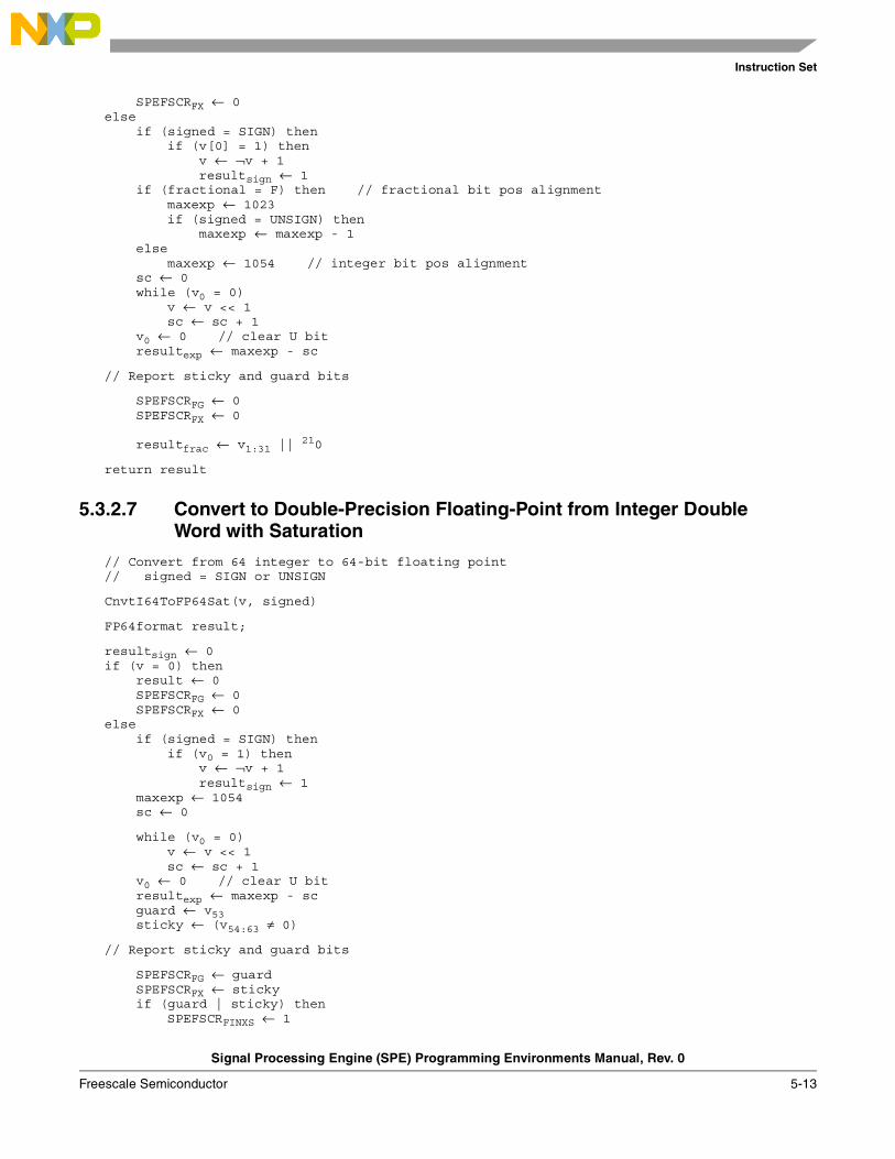
Instruction Set
Signal Processing Engine (SPE) Programming Environments Manual, Rev. 0
Freescale Semiconductor 5-13
SPEFSCRFX ← 0else
if (signed = SIGN) thenif (v[0] = 1) then
v ← ¬v + 1resultsign ← 1
if (fractional = F) then // fractional bit pos alignmentmaxexp ← 1023if (signed = UNSIGN) then
maxexp ← maxexp - 1else
maxexp ← 1054 // integer bit pos alignmentsc ← 0while (v0 = 0)
v ← v << 1sc ← sc + 1
v0 ← 0 // clear U bitresultexp ← maxexp - sc
// Report sticky and guard bits
SPEFSCRFG ← 0SPEFSCRFX ← 0
resultfrac ← v1:31 || 210
return result
5.3.2.7 Convert to Double-Precision Floating-Point from Integer Double Word with Saturation
// Convert from 64 integer to 64-bit floating point// signed = SIGN or UNSIGN
CnvtI64ToFP64Sat(v, signed)
FP64format result;
resultsign ← 0if (v = 0) then
result ← 0SPEFSCRFG ← 0SPEFSCRFX ← 0
elseif (signed = SIGN) then
if (v0 = 1) thenv ← ¬v + 1resultsign ← 1
maxexp ← 1054sc ← 0
while (v0 = 0)v ← v << 1sc ← sc + 1
v0 ← 0 // clear U bitresultexp ← maxexp - scguard ← v53sticky ← (v54:63 ≠ 0)
// Report sticky and guard bits
SPEFSCRFG ← guardSPEFSCRFX ← stickyif (guard | sticky) then
SPEFSCRFINXS ← 1
Instruction Set
Signal Processing Engine (SPE) Programming Environments Manual, Rev. 0
5-14 Freescale Semiconductor
// Round the result
resultfrac ← v1:52result ← Round64(result, guard, sticky)
return result
5.3.3 Integer Saturation Models// Saturate after addition
SATURATE(ovf, carry, neg_sat, pos_sat, value)
if ovf thenif carry then
return neg_satelse
return pos_satelse
return value
5.3.4 Embedded Floating-Point Results
Section 5.3.4, “Embedded Floating-Point Results,” summarizes results of various types of SPE and embedded floating-point operations on various combinations of input operands.
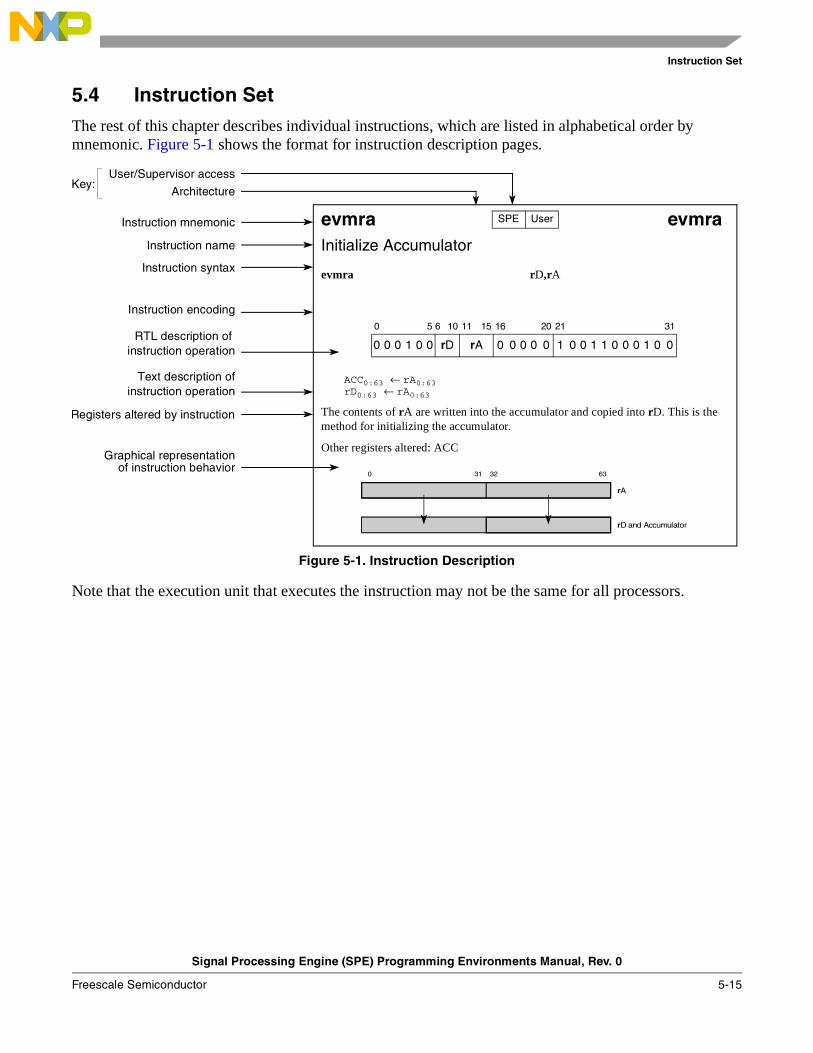
Instruction Set
Signal Processing Engine (SPE) Programming Environments Manual, Rev. 0
Freescale Semiconductor 5-15
5.4 Instruction SetThe rest of this chapter describes individual instructions, which are listed in alphabetical order by mnemonic. Figure 5-1 shows the format for instruction description pages.
Figure 5-1. Instruction Description
Note that the execution unit that executes the instruction may not be the same for all processors.
evmra evmraInitialize Accumulator
evmra rD,rA
ACC0:63 ← rA0:63rD0:63 ← rA0:63
The contents of rA are written into the accumulator and copied into rD. This is the method for initializing the accumulator.
Other registers altered: ACC
0 5 6 10 11 15 16 20 21 31
0 0 0 1 0 0 rD rA 0 0 0 0 0 1 0 0 1 1 0 0 0 1 0 0
SPE User
0 31 32 63
rA
rD and Accumulator
Instruction mnemonic
Instruction name
Instruction syntax
Instruction encoding
RTL description of
Text description of
Registers altered by instruction
instruction operation
instruction operation
User/Supervisor access
ArchitectureKey:
Graphical representationof instruction behavior
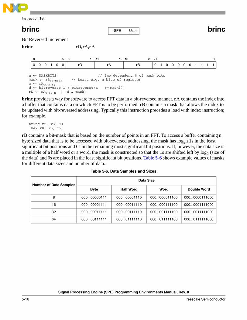
Instruction Set
Signal Processing Engine (SPE) Programming Environments Manual, Rev. 0
5-16 Freescale Semiconductor
brinc brincBit Reversed Increment
brinc rD,rA,rB
n ← MASKBITS // Imp dependent # of mask bitsmask ← rB64-n:63 // Least sig. n bits of registera ← rA64-n:63d ← bitreverse(1 + bitreverse(a | (¬ mask)))rD ← rA0:63-n || (d & mask)
brinc provides a way for software to access FFT data in a bit-reversed manner. rA contains the index into a buffer that contains data on which FFT is to be performed. rB contains a mask that allows the index to be updated with bit-reversed addressing. Typically this instruction precedes a load with index instruction; for example,
brinc r2, r3, r4lhax r8, r5, r2
rB contains a bit-mask that is based on the number of points in an FFT. To access a buffer containing n byte sized data that is to be accessed with bit-reversed addressing, the mask has log2n 1s in the least significant bit positions and 0s in the remaining most significant bit positions. If, however, the data size is a multiple of a half word or a word, the mask is constructed so that the 1s are shifted left by log2 (size of the data) and 0s are placed in the least significant bit positions. Table 5-6 shows example values of masks for different data sizes and number of data.
0 5 6 10 11 15 16 20 21 31
0 0 0 1 0 0 rD rA rB 0 1 0 0 0 0 0 1 1 1 1
Table 5-6. Data Samples and Sizes
Number of Data SamplesData Size
Byte Half Word Word Double Word
8 000...00000111 000...00001110 000...000011100 000...0000111000
16 000...00001111 000...00011110 000...000111100 000...0001111000
32 000...00011111 000...00111110 000...001111100 000...0011111000
64 000...00111111 000...01111110 000...011111100 000...0111111000
SPE User

Instruction Set
Signal Processing Engine (SPE) Programming Environments Manual, Rev. 0
Freescale Semiconductor 5-17
efdabs efdabsFloating-Point Double-Precision Absolute Value
efdabs rD,rA
rD0:63 ← 0b0 || rA1:63
The sign bit of rA is set to 0 and the result is placed into rD.
Exceptions:
Exception detection for embedded floating-point absolute value operations is implementation dependent. An implementation may choose to not detect exceptions and carry out the sign bit operation. If the implementation does not detect exceptions, or if exception detection is disabled, the computation can be carried out in one of two ways, as a sign bit operation ignoring the rest of the contents of the source register, or by examining the input and appropriately saturating the input prior to performing the operation.
If an implementation chooses to handle exceptions, the exception is handled as follows: If rA is infinity, denorm, or NaN, SPEFSCR[FINV] is set, and FG and FX are cleared. If floating-point invalid input exceptions are enabled, an interrupt is taken and the destination register is not updated.
0 5 6 10 11 15 16 20 21 31
0 0 0 1 0 0 rD rA 0 0 0 0 0 0 1 0 1 1 1 0 0 1 0 0
SPE FD User
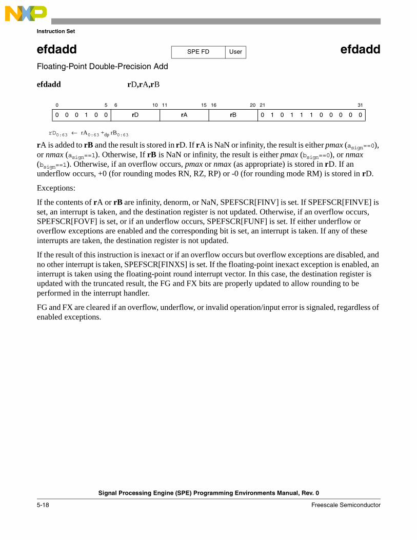
Instruction Set
Signal Processing Engine (SPE) Programming Environments Manual, Rev. 0
5-18 Freescale Semiconductor
efdadd efdaddFloating-Point Double-Precision Add
efdadd rD,rA,rB
rD0:63 ← rA0:63 +dp rB0:63
rA is added to rB and the result is stored in rD. If rA is NaN or infinity, the result is either pmax (asign==0), or nmax (asign==1). Otherwise, If rB is NaN or infinity, the result is either pmax (bsign==0), or nmax (bsign==1). Otherwise, if an overflow occurs, pmax or nmax (as appropriate) is stored in rD. If an underflow occurs, +0 (for rounding modes RN, RZ, RP) or -0 (for rounding mode RM) is stored in rD.
Exceptions:
If the contents of rA or rB are infinity, denorm, or NaN, SPEFSCR[FINV] is set. If SPEFSCR[FINVE] is set, an interrupt is taken, and the destination register is not updated. Otherwise, if an overflow occurs, SPEFSCR[FOVF] is set, or if an underflow occurs, SPEFSCR[FUNF] is set. If either underflow or overflow exceptions are enabled and the corresponding bit is set, an interrupt is taken. If any of these interrupts are taken, the destination register is not updated.
If the result of this instruction is inexact or if an overflow occurs but overflow exceptions are disabled, and no other interrupt is taken, SPEFSCR[FINXS] is set. If the floating-point inexact exception is enabled, an interrupt is taken using the floating-point round interrupt vector. In this case, the destination register is updated with the truncated result, the FG and FX bits are properly updated to allow rounding to be performed in the interrupt handler.
FG and FX are cleared if an overflow, underflow, or invalid operation/input error is signaled, regardless of enabled exceptions.
0 5 6 10 11 15 16 20 21 31
0 0 0 1 0 0 rD rA rB 0 1 0 1 1 1 0 0 0 0 0
SPE FD User
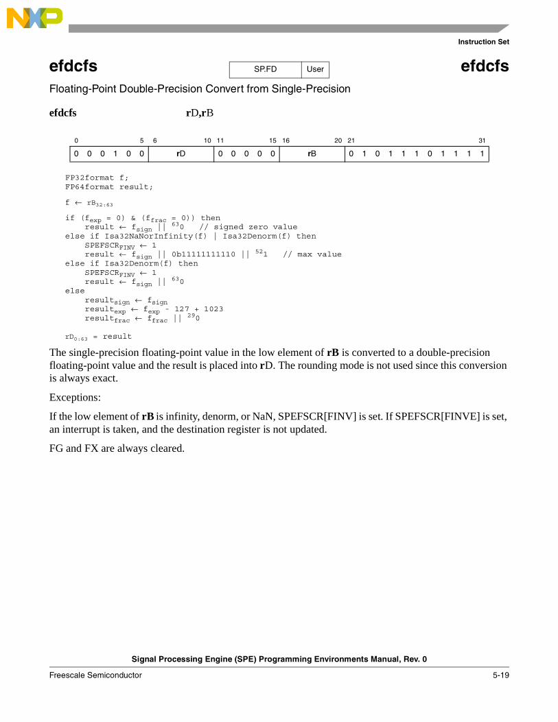
Instruction Set
Signal Processing Engine (SPE) Programming Environments Manual, Rev. 0
Freescale Semiconductor 5-19
efdcfs efdcfsFloating-Point Double-Precision Convert from Single-Precision
efdcfs rD,rB
FP32format f;FP64format result;
f ← rB32:63
if (fexp = 0) & (ffrac = 0)) thenresult ← fsign ||
630 // signed zero valueelse if Isa32NaNorInfinity(f) | Isa32Denorm(f) then
SPEFSCRFINV ← 1result ← fsign || 0b11111111110 ||
521 // max valueelse if Isa32Denorm(f) then
SPEFSCRFINV ← 1result ← fsign ||
630else
resultsign ← fsignresultexp ← fexp - 127 + 1023resultfrac ← ffrac ||
290
rD0:63 = result
The single-precision floating-point value in the low element of rB is converted to a double-precision floating-point value and the result is placed into rD. The rounding mode is not used since this conversion is always exact.
Exceptions:
If the low element of rB is infinity, denorm, or NaN, SPEFSCR[FINV] is set. If SPEFSCR[FINVE] is set, an interrupt is taken, and the destination register is not updated.
FG and FX are always cleared.
0 5 6 10 11 15 16 20 21 31
0 0 0 1 0 0 rD 0 0 0 0 0 rB 0 1 0 1 1 1 0 1 1 1 1
SP.FD User

Instruction Set
Signal Processing Engine (SPE) Programming Environments Manual, Rev. 0
5-20 Freescale Semiconductor
efdcfsf efdcfsfConvert Floating-Point Double-Precision from Signed Fraction
efdcfsf rD,rB
rD0:63 ← CnvtI32ToFP64(rB32:63, SIGN, F)
The signed fractional low element in rB is converted to a double-precision floating-point value using the current rounding mode and the result is placed into rD.
Exceptions:
None.
0 5 6 10 11 15 16 20 21 31
0 0 0 1 0 0 rD 0 0 0 0 0 rB 0 1 0 1 1 1 1 0 0 1 1
SPE FD User

Instruction Set
Signal Processing Engine (SPE) Programming Environments Manual, Rev. 0
Freescale Semiconductor 5-21
efdcfsi efdcfsi Convert Floating-Point Double-Precision from Signed Integer
efdcfsi rD,rB
rD0:63 ← CnvtSI32ToFP64(rB32:63, SIGN, I)
The signed integer low element in rB is converted to a double-precision floating-point value using the current rounding mode and the result is placed into rD.
Exceptions:
None.
0 5 6 10 11 15 16 20 21 31
0 0 0 1 0 0 rD 0 0 0 0 0 rB 0 1 0 1 1 1 1 0 0 0 1
SPE FD User

Instruction Set
Signal Processing Engine (SPE) Programming Environments Manual, Rev. 0
5-22 Freescale Semiconductor
efdcfsid efdcfsid Convert Floating-Point Double-Precision from Signed Integer Doubleword
efdcfsid rD,rB
rD0:63 ← CnvtI64ToFP64(rB0:63, SIGN)
The signed integer doubleword in rB is converted to a double-precision floating-point value using the current rounding mode and the result is placed into rD.
Exceptions:
This instruction can signal an inexact status and set SPEFSCR[FINXS] if the conversion is not exact. If the floating-point inexact exception is enabled, an interrupt is taken using the floating-point round interrupt vector. In this case, the destination register is updated with the truncated result, the FG and FX bits are properly updated to allow rounding to be performed in the interrupt handler.
This instruction may only be implemented for 64-bit implementations.
0 5 6 10 11 15 16 20 21 31
0 0 0 1 0 0 rD 0 0 0 0 0 rB 0 1 0 1 1 1 0 0 0 1 1
SPE FD User

Instruction Set
Signal Processing Engine (SPE) Programming Environments Manual, Rev. 0
Freescale Semiconductor 5-23
efdcfuf efdcfufConvert Floating-Point Double-Precision from Unsigned Fraction
efdcfuf rD,rB
rD0:63 ← CnvtI32ToFP64(rB32:63, UNSIGN, F)
The unsigned fractional low element in rB is converted to a double-precision floating-point value using the current rounding mode and the result is placed into rD.
Exceptions:
None.
0 5 6 10 11 15 16 20 21 31
0 0 0 1 0 0 rD 0 0 0 0 0 rB 0 1 0 1 1 1 1 0 0 1 0
SPE FD User

Instruction Set
Signal Processing Engine (SPE) Programming Environments Manual, Rev. 0
5-24 Freescale Semiconductor
efdcfui efdcfui Convert Floating-Point Double-Precision from Unsigned Integer
efdcfui rD,rB
rD0:63 ← CnvtSI32ToFP64(rB32:63, UNSIGN, I)
The unsigned integer low element in rB is converted to a double-precision floating-point value using the current rounding mode and the result is placed into rD.
Exceptions:
None.
0 5 6 10 11 15 16 20 21 31
0 0 0 1 0 0 rD 0 0 0 0 0 rB 0 1 0 1 1 1 1 0 0 0 0
SPE FD User

Instruction Set
Signal Processing Engine (SPE) Programming Environments Manual, Rev. 0
Freescale Semiconductor 5-25
efdcfuid efdcfuid Convert Floating-Point Double-Precision from Unsigned Integer Doubleword
efdcfuid rD,rB
rD0:63 ← CnvtI64ToFP64(rB0:63, UNSIGN)
The unsigned integer doubleword in rB is converted to a double-precision floating-point value using the current rounding mode and the result is placed into rD.
Exceptions:
This instruction can signal an inexact status and set SPEFSCR[FINXS] if the conversion is not exact. If the floating-point inexact exception is enabled, an interrupt is taken using the floating-point round interrupt vector. In this case, the destination register is updated with the truncated result, the FG and FX bits are properly updated to allow rounding to be performed in the interrupt handler.
This instruction may only be implemented for 64-bit implementations.
0 5 6 10 11 15 16 20 21 31
0 0 0 1 0 0 rD 0 0 0 0 0 rB 0 1 0 1 1 1 0 0 0 1 0
SPE FD User
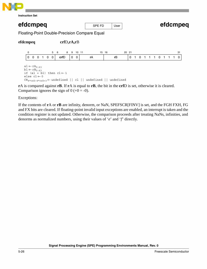
Instruction Set
Signal Processing Engine (SPE) Programming Environments Manual, Rev. 0
5-26 Freescale Semiconductor
efdcmpeq efdcmpeqFloating-Point Double-Precision Compare Equal
efdcmpeq crfD,rA,rB
al ← rA0:63bl ← rB0:63if (al = bl) then cl ← 1else cl ← 0CR4*crD:4*crD+3 ← undefined || cl || undefined || undefined
rA is compared against rB. If rA is equal to rB, the bit in the crfD is set, otherwise it is cleared. Comparison ignores the sign of 0 (+0 = -0).
Exceptions:
If the contents of rA or rB are infinity, denorm, or NaN, SPEFSCR[FINV] is set, and the FGH FXH, FG and FX bits are cleared. If floating-point invalid input exceptions are enabled, an interrupt is taken and the condition register is not updated. Otherwise, the comparison proceeds after treating NaNs, infinities, and denorms as normalized numbers, using their values of ‘e’ and ‘f’ directly.
0 5 6 8 9 10 11 15 16 20 21 31
0 0 0 1 0 0 crfD 0 0 rA rB 0 1 0 1 1 1 0 1 1 1 0
SPE FD User
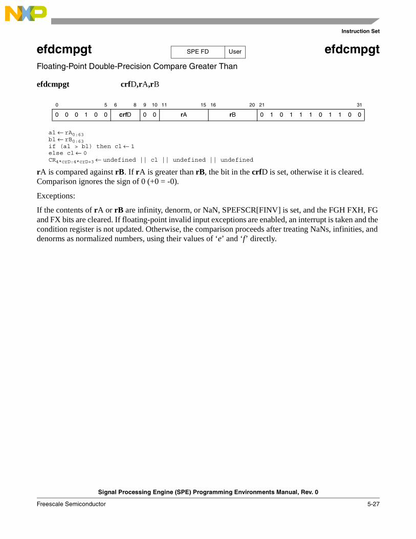
Instruction Set
Signal Processing Engine (SPE) Programming Environments Manual, Rev. 0
Freescale Semiconductor 5-27
efdcmpgt efdcmpgtFloating-Point Double-Precision Compare Greater Than
efdcmpgt crfD,rA,rB
al ← rA0:63bl ← rB0:63if (al > bl) then cl ← 1else cl ← 0CR4*crD:4*crD+3 ← undefined || cl || undefined || undefined
rA is compared against rB. If rA is greater than rB, the bit in the crfD is set, otherwise it is cleared. Comparison ignores the sign of 0 (+0 = -0).
Exceptions:
If the contents of rA or rB are infinity, denorm, or NaN, SPEFSCR[FINV] is set, and the FGH FXH, FG and FX bits are cleared. If floating-point invalid input exceptions are enabled, an interrupt is taken and the condition register is not updated. Otherwise, the comparison proceeds after treating NaNs, infinities, and denorms as normalized numbers, using their values of ‘e’ and ‘f’ directly.
0 5 6 8 9 10 11 15 16 20 21 31
0 0 0 1 0 0 crfD 0 0 rA rB 0 1 0 1 1 1 0 1 1 0 0
SPE FD User
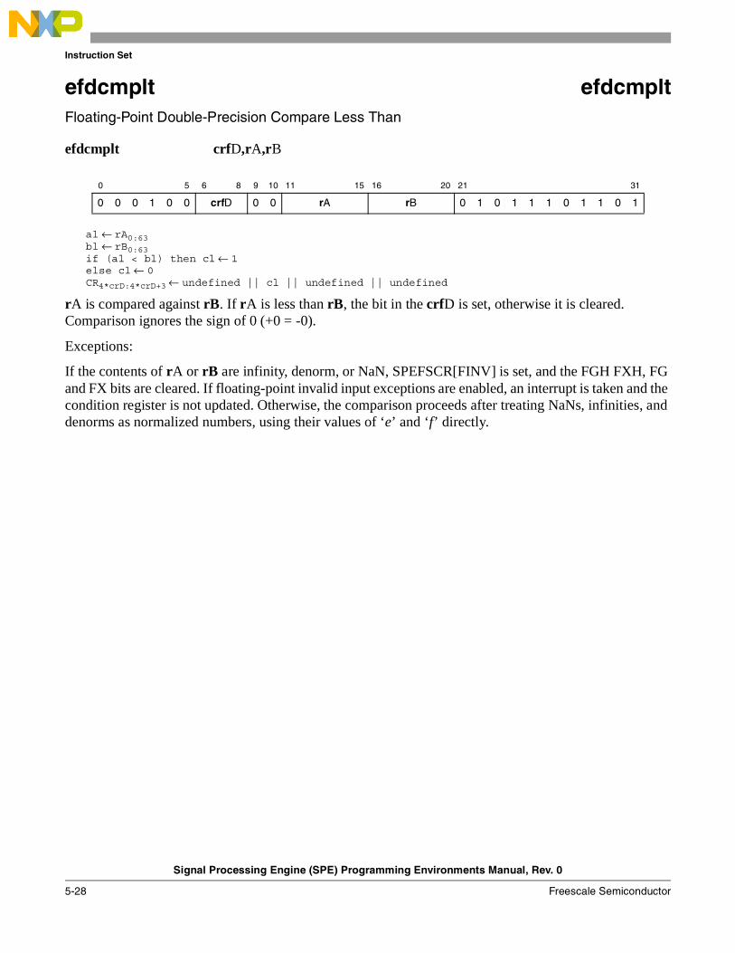
Instruction Set
Signal Processing Engine (SPE) Programming Environments Manual, Rev. 0
5-28 Freescale Semiconductor
efdcmplt efdcmpltFloating-Point Double-Precision Compare Less Than
efdcmplt crfD,rA,rB
al ← rA0:63bl ← rB0:63if (al < bl) then cl ← 1else cl ← 0CR4*crD:4*crD+3 ← undefined || cl || undefined || undefined
rA is compared against rB. If rA is less than rB, the bit in the crfD is set, otherwise it is cleared. Comparison ignores the sign of 0 (+0 = -0).
Exceptions:
If the contents of rA or rB are infinity, denorm, or NaN, SPEFSCR[FINV] is set, and the FGH FXH, FG and FX bits are cleared. If floating-point invalid input exceptions are enabled, an interrupt is taken and the condition register is not updated. Otherwise, the comparison proceeds after treating NaNs, infinities, and denorms as normalized numbers, using their values of ‘e’ and ‘f’ directly.
0 5 6 8 9 10 11 15 16 20 21 31
0 0 0 1 0 0 crfD 0 0 rA rB 0 1 0 1 1 1 0 1 1 0 1
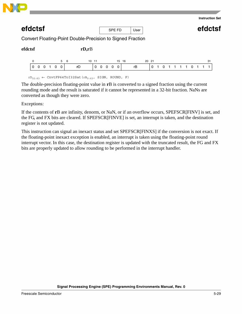
Instruction Set
Signal Processing Engine (SPE) Programming Environments Manual, Rev. 0
Freescale Semiconductor 5-29
efdctsf efdctsfConvert Floating-Point Double-Precision to Signed Fraction
efdctsf rD,rB
rD32:63 ← CnvtFP64ToI32Sat(rB0:63, SIGN, ROUND, F)
The double-precision floating-point value in rB is converted to a signed fraction using the current rounding mode and the result is saturated if it cannot be represented in a 32-bit fraction. NaNs are converted as though they were zero.
Exceptions:
If the contents of rB are infinity, denorm, or NaN, or if an overflow occurs, SPEFSCR[FINV] is set, and the FG, and FX bits are cleared. If SPEFSCR[FINVE] is set, an interrupt is taken, and the destination register is not updated.
This instruction can signal an inexact status and set SPEFSCR[FINXS] if the conversion is not exact. If the floating-point inexact exception is enabled, an interrupt is taken using the floating-point round interrupt vector. In this case, the destination register is updated with the truncated result, the FG and FX bits are properly updated to allow rounding to be performed in the interrupt handler.
0 5 6 10 11 15 16 20 21 31
0 0 0 1 0 0 rD 0 0 0 0 0 rB 0 1 0 1 1 1 1 0 1 1 1
SPE FD User
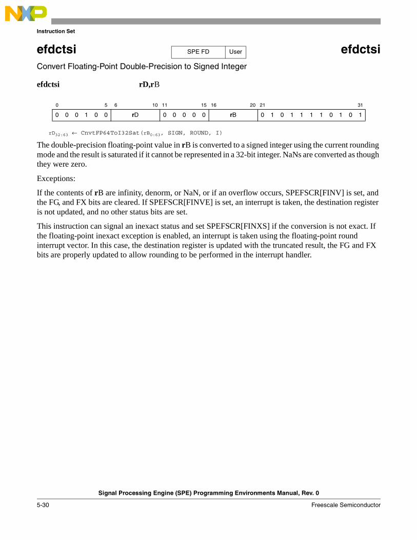
Instruction Set
Signal Processing Engine (SPE) Programming Environments Manual, Rev. 0
5-30 Freescale Semiconductor
efdctsi efdctsi Convert Floating-Point Double-Precision to Signed Integer
efdctsi rD,rB
rD32:63 ← CnvtFP64ToI32Sat(rB0:63, SIGN, ROUND, I)
The double-precision floating-point value in rB is converted to a signed integer using the current rounding mode and the result is saturated if it cannot be represented in a 32-bit integer. NaNs are converted as though they were zero.
Exceptions:
If the contents of rB are infinity, denorm, or NaN, or if an overflow occurs, SPEFSCR[FINV] is set, and the FG, and FX bits are cleared. If SPEFSCR[FINVE] is set, an interrupt is taken, the destination register is not updated, and no other status bits are set.
This instruction can signal an inexact status and set SPEFSCR[FINXS] if the conversion is not exact. If the floating-point inexact exception is enabled, an interrupt is taken using the floating-point round interrupt vector. In this case, the destination register is updated with the truncated result, the FG and FX bits are properly updated to allow rounding to be performed in the interrupt handler.
0 5 6 10 11 15 16 20 21 31
0 0 0 1 0 0 rD 0 0 0 0 0 rB 0 1 0 1 1 1 1 0 1 0 1
SPE FD User
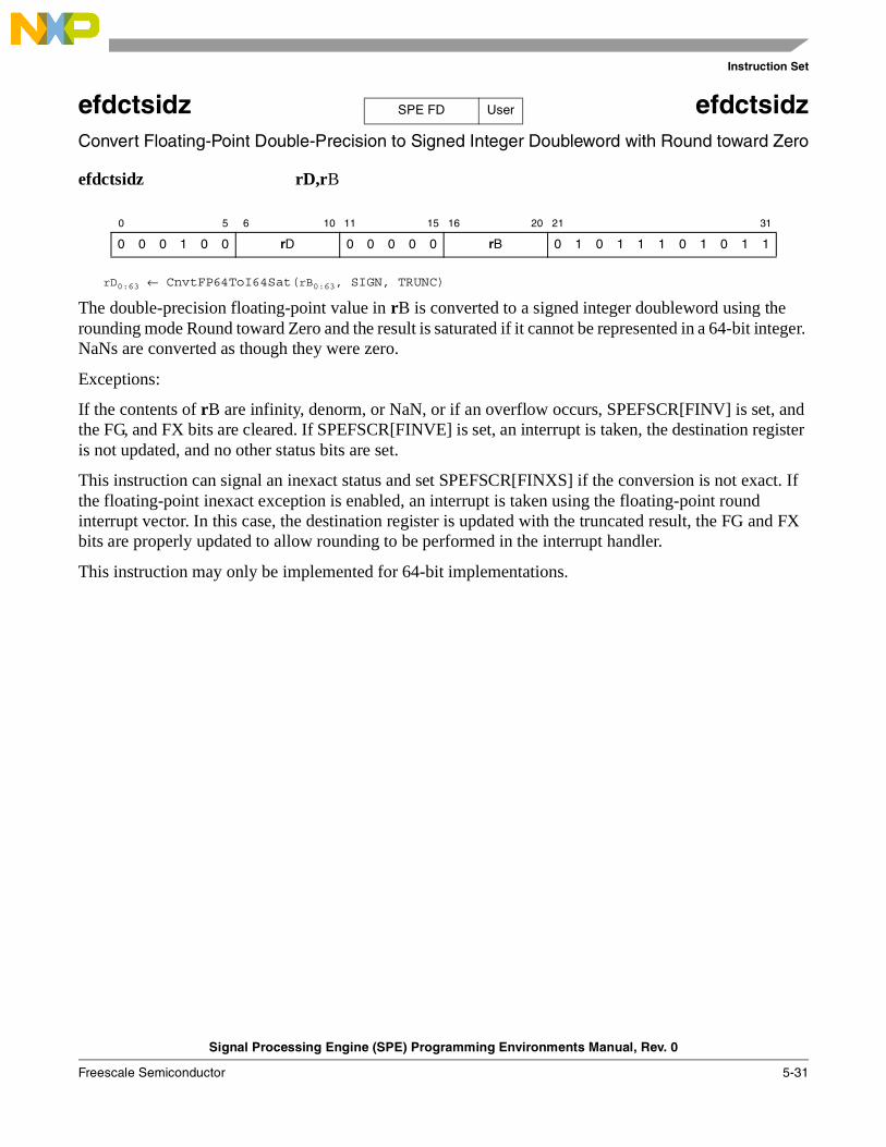
Instruction Set
Signal Processing Engine (SPE) Programming Environments Manual, Rev. 0
Freescale Semiconductor 5-31
efdctsidz efdctsidz Convert Floating-Point Double-Precision to Signed Integer Doubleword with Round toward Zero
efdctsidz rD,rB
rD0:63 ← CnvtFP64ToI64Sat(rB0:63, SIGN, TRUNC)
The double-precision floating-point value in rB is converted to a signed integer doubleword using the rounding mode Round toward Zero and the result is saturated if it cannot be represented in a 64-bit integer. NaNs are converted as though they were zero.
Exceptions:
If the contents of rB are infinity, denorm, or NaN, or if an overflow occurs, SPEFSCR[FINV] is set, and the FG, and FX bits are cleared. If SPEFSCR[FINVE] is set, an interrupt is taken, the destination register is not updated, and no other status bits are set.
This instruction can signal an inexact status and set SPEFSCR[FINXS] if the conversion is not exact. If the floating-point inexact exception is enabled, an interrupt is taken using the floating-point round interrupt vector. In this case, the destination register is updated with the truncated result, the FG and FX bits are properly updated to allow rounding to be performed in the interrupt handler.
This instruction may only be implemented for 64-bit implementations.
0 5 6 10 11 15 16 20 21 31
0 0 0 1 0 0 rD 0 0 0 0 0 rB 0 1 0 1 1 1 0 1 0 1 1
SPE FD User
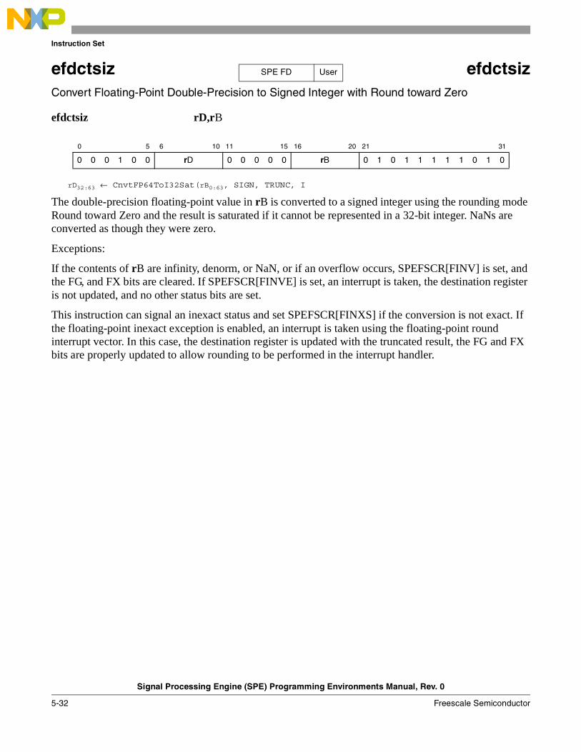
Instruction Set
Signal Processing Engine (SPE) Programming Environments Manual, Rev. 0
5-32 Freescale Semiconductor
efdctsiz efdctsiz Convert Floating-Point Double-Precision to Signed Integer with Round toward Zero
efdctsiz rD,rB
rD32:63 ← CnvtFP64ToI32Sat(rB0:63, SIGN, TRUNC, I
The double-precision floating-point value in rB is converted to a signed integer using the rounding mode Round toward Zero and the result is saturated if it cannot be represented in a 32-bit integer. NaNs are converted as though they were zero.
Exceptions:
If the contents of rB are infinity, denorm, or NaN, or if an overflow occurs, SPEFSCR[FINV] is set, and the FG, and FX bits are cleared. If SPEFSCR[FINVE] is set, an interrupt is taken, the destination register is not updated, and no other status bits are set.
This instruction can signal an inexact status and set SPEFSCR[FINXS] if the conversion is not exact. If the floating-point inexact exception is enabled, an interrupt is taken using the floating-point round interrupt vector. In this case, the destination register is updated with the truncated result, the FG and FX bits are properly updated to allow rounding to be performed in the interrupt handler.
0 5 6 10 11 15 16 20 21 31
0 0 0 1 0 0 rD 0 0 0 0 0 rB 0 1 0 1 1 1 1 1 0 1 0
SPE FD User
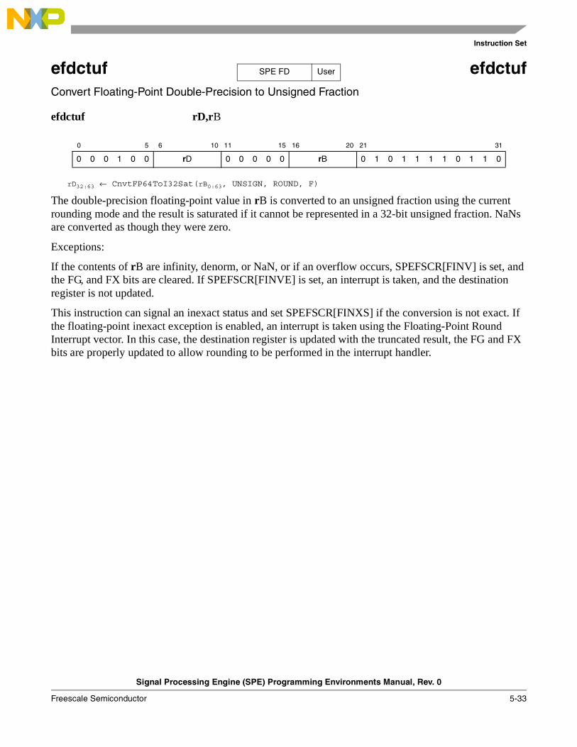
Instruction Set
Signal Processing Engine (SPE) Programming Environments Manual, Rev. 0
Freescale Semiconductor 5-33
efdctuf efdctufConvert Floating-Point Double-Precision to Unsigned Fraction
efdctuf rD,rB
rD32:63 ← CnvtFP64ToI32Sat(rB0:63, UNSIGN, ROUND, F)
The double-precision floating-point value in rB is converted to an unsigned fraction using the current rounding mode and the result is saturated if it cannot be represented in a 32-bit unsigned fraction. NaNs are converted as though they were zero.
Exceptions:
If the contents of rB are infinity, denorm, or NaN, or if an overflow occurs, SPEFSCR[FINV] is set, and the FG, and FX bits are cleared. If SPEFSCR[FINVE] is set, an interrupt is taken, and the destination register is not updated.
This instruction can signal an inexact status and set SPEFSCR[FINXS] if the conversion is not exact. If the floating-point inexact exception is enabled, an interrupt is taken using the Floating-Point Round Interrupt vector. In this case, the destination register is updated with the truncated result, the FG and FX bits are properly updated to allow rounding to be performed in the interrupt handler.
0 5 6 10 11 15 16 20 21 31
0 0 0 1 0 0 rD 0 0 0 0 0 rB 0 1 0 1 1 1 1 0 1 1 0
SPE FD User
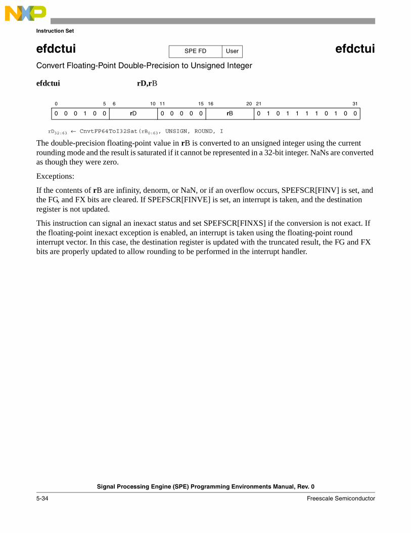
Instruction Set
Signal Processing Engine (SPE) Programming Environments Manual, Rev. 0
5-34 Freescale Semiconductor
efdctui efdctui Convert Floating-Point Double-Precision to Unsigned Integer
efdctui rD,rB
rD32:63 ← CnvtFP64ToI32Sat(rB0:63, UNSIGN, ROUND, I
The double-precision floating-point value in rB is converted to an unsigned integer using the current rounding mode and the result is saturated if it cannot be represented in a 32-bit integer. NaNs are converted as though they were zero.
Exceptions:
If the contents of rB are infinity, denorm, or NaN, or if an overflow occurs, SPEFSCR[FINV] is set, and the FG, and FX bits are cleared. If SPEFSCR[FINVE] is set, an interrupt is taken, and the destination register is not updated.
This instruction can signal an inexact status and set SPEFSCR[FINXS] if the conversion is not exact. If the floating-point inexact exception is enabled, an interrupt is taken using the floating-point round interrupt vector. In this case, the destination register is updated with the truncated result, the FG and FX bits are properly updated to allow rounding to be performed in the interrupt handler.
0 5 6 10 11 15 16 20 21 31
0 0 0 1 0 0 rD 0 0 0 0 0 rB 0 1 0 1 1 1 1 0 1 0 0
SPE FD User
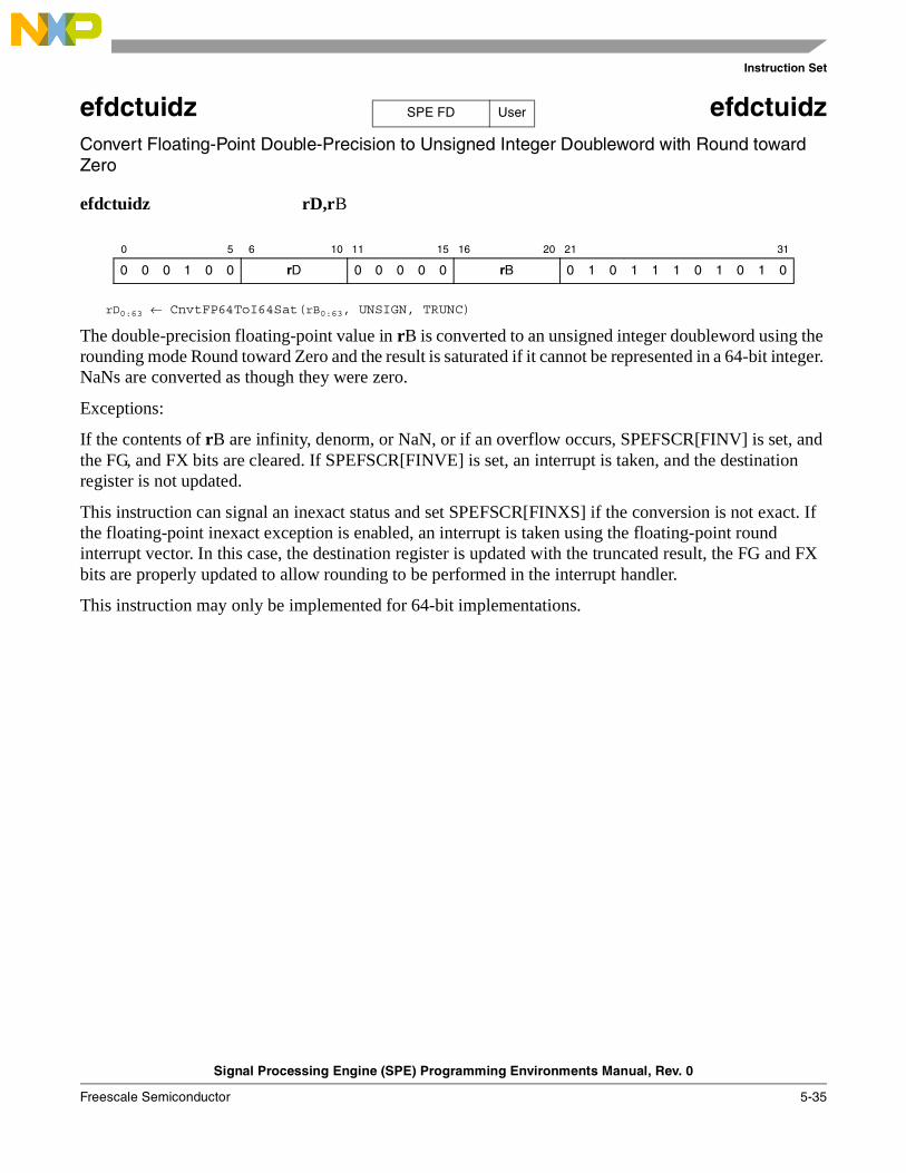
Instruction Set
Signal Processing Engine (SPE) Programming Environments Manual, Rev. 0
Freescale Semiconductor 5-35
efdctuidz efdctuidz Convert Floating-Point Double-Precision to Unsigned Integer Doubleword with Round toward Zero
efdctuidz rD,rB
rD0:63 ← CnvtFP64ToI64Sat(rB0:63, UNSIGN, TRUNC)
The double-precision floating-point value in rB is converted to an unsigned integer doubleword using the rounding mode Round toward Zero and the result is saturated if it cannot be represented in a 64-bit integer. NaNs are converted as though they were zero.
Exceptions:
If the contents of rB are infinity, denorm, or NaN, or if an overflow occurs, SPEFSCR[FINV] is set, and the FG, and FX bits are cleared. If SPEFSCR[FINVE] is set, an interrupt is taken, and the destination register is not updated.
This instruction can signal an inexact status and set SPEFSCR[FINXS] if the conversion is not exact. If the floating-point inexact exception is enabled, an interrupt is taken using the floating-point round interrupt vector. In this case, the destination register is updated with the truncated result, the FG and FX bits are properly updated to allow rounding to be performed in the interrupt handler.
This instruction may only be implemented for 64-bit implementations.
0 5 6 10 11 15 16 20 21 31
0 0 0 1 0 0 rD 0 0 0 0 0 rB 0 1 0 1 1 1 0 1 0 1 0
SPE FD User
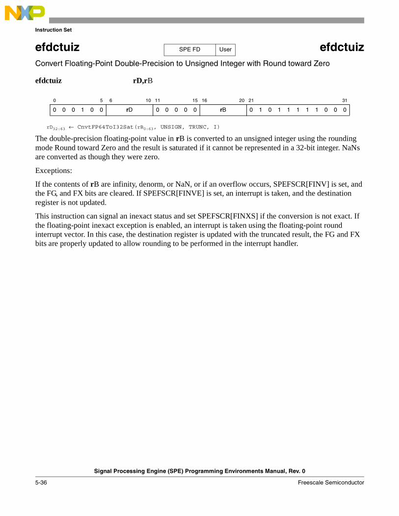
Instruction Set
Signal Processing Engine (SPE) Programming Environments Manual, Rev. 0
5-36 Freescale Semiconductor
efdctuiz efdctuiz Convert Floating-Point Double-Precision to Unsigned Integer with Round toward Zero
efdctuiz rD,rB
rD32:63 ← CnvtFP64ToI32Sat(rB0:63, UNSIGN, TRUNC, I)
The double-precision floating-point value in rB is converted to an unsigned integer using the rounding mode Round toward Zero and the result is saturated if it cannot be represented in a 32-bit integer. NaNs are converted as though they were zero.
Exceptions:
If the contents of rB are infinity, denorm, or NaN, or if an overflow occurs, SPEFSCR[FINV] is set, and the FG, and FX bits are cleared. If SPEFSCR[FINVE] is set, an interrupt is taken, and the destination register is not updated.
This instruction can signal an inexact status and set SPEFSCR[FINXS] if the conversion is not exact. If the floating-point inexact exception is enabled, an interrupt is taken using the floating-point round interrupt vector. In this case, the destination register is updated with the truncated result, the FG and FX bits are properly updated to allow rounding to be performed in the interrupt handler.
0 5 6 10 11 15 16 20 21 31
0 0 0 1 0 0 rD 0 0 0 0 0 rB 0 1 0 1 1 1 1 1 0 0 0
SPE FD User
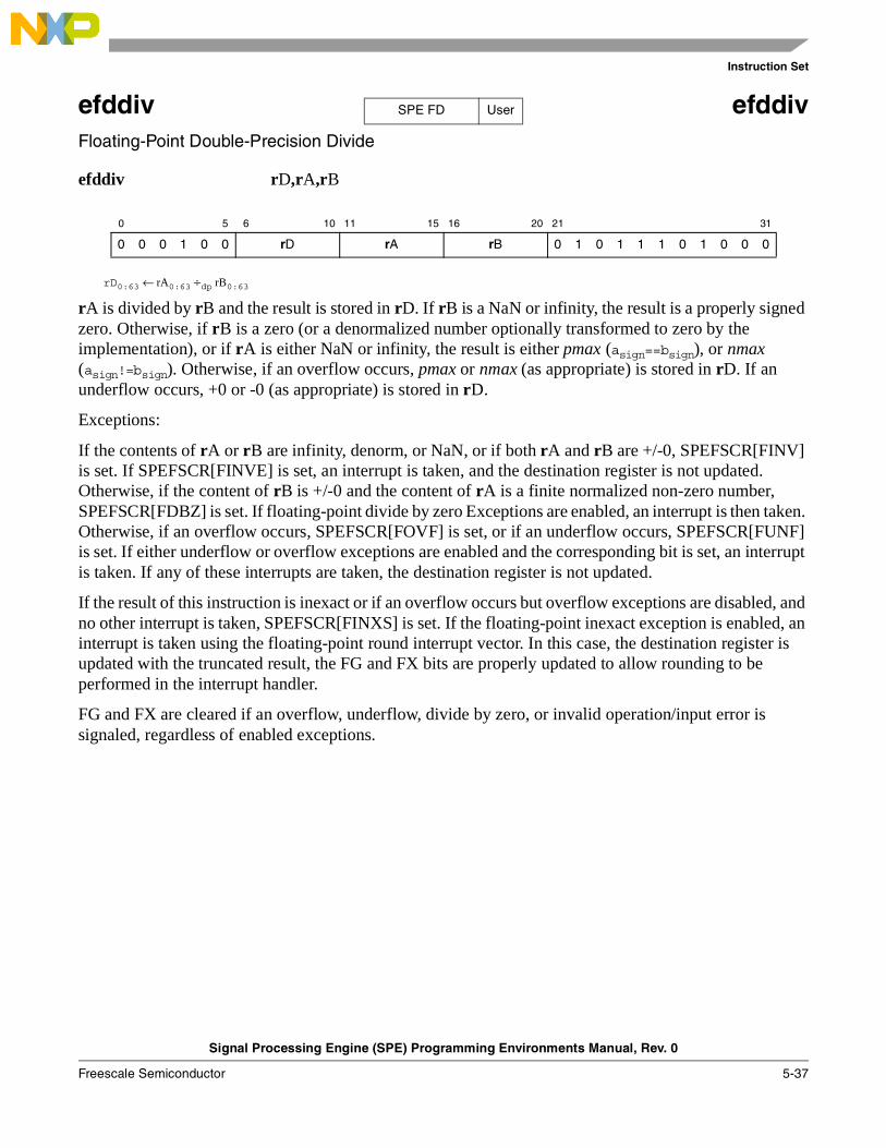
Instruction Set
Signal Processing Engine (SPE) Programming Environments Manual, Rev. 0
Freescale Semiconductor 5-37
efddiv efddivFloating-Point Double-Precision Divide
efddiv rD,rA,rB
rD0:63 ← rA0:63 ÷dp rB0:63
rA is divided by rB and the result is stored in rD. If rB is a NaN or infinity, the result is a properly signed zero. Otherwise, if rB is a zero (or a denormalized number optionally transformed to zero by the implementation), or if rA is either NaN or infinity, the result is either pmax (asign==bsign), or nmax (asign!=bsign). Otherwise, if an overflow occurs, pmax or nmax (as appropriate) is stored in rD. If an underflow occurs, +0 or -0 (as appropriate) is stored in rD.
Exceptions:
If the contents of rA or rB are infinity, denorm, or NaN, or if both rA and rB are +/-0, SPEFSCR[FINV] is set. If SPEFSCR[FINVE] is set, an interrupt is taken, and the destination register is not updated. Otherwise, if the content of rB is +/-0 and the content of rA is a finite normalized non-zero number, SPEFSCR[FDBZ] is set. If floating-point divide by zero Exceptions are enabled, an interrupt is then taken. Otherwise, if an overflow occurs, SPEFSCR[FOVF] is set, or if an underflow occurs, SPEFSCR[FUNF] is set. If either underflow or overflow exceptions are enabled and the corresponding bit is set, an interrupt is taken. If any of these interrupts are taken, the destination register is not updated.
If the result of this instruction is inexact or if an overflow occurs but overflow exceptions are disabled, and no other interrupt is taken, SPEFSCR[FINXS] is set. If the floating-point inexact exception is enabled, an interrupt is taken using the floating-point round interrupt vector. In this case, the destination register is updated with the truncated result, the FG and FX bits are properly updated to allow rounding to be performed in the interrupt handler.
FG and FX are cleared if an overflow, underflow, divide by zero, or invalid operation/input error is signaled, regardless of enabled exceptions.
0 5 6 10 11 15 16 20 21 31
0 0 0 1 0 0 rD rA rB 0 1 0 1 1 1 0 1 0 0 0
SPE FD User
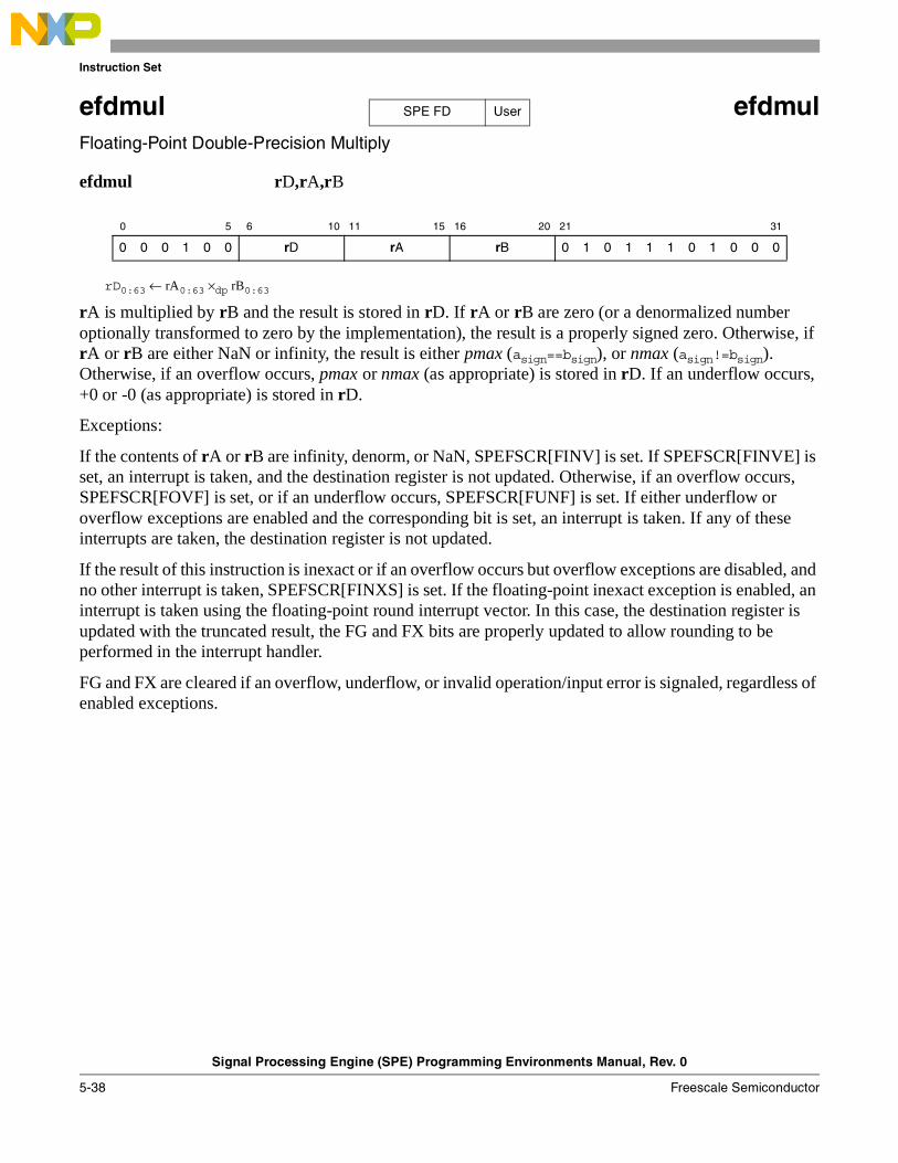
Instruction Set
Signal Processing Engine (SPE) Programming Environments Manual, Rev. 0
5-38 Freescale Semiconductor
efdmul efdmulFloating-Point Double-Precision Multiply
efdmul rD,rA,rB
rD0:63 ← rA0:63 ×dp rB0:63
rA is multiplied by rB and the result is stored in rD. If rA or rB are zero (or a denormalized number optionally transformed to zero by the implementation), the result is a properly signed zero. Otherwise, if rA or rB are either NaN or infinity, the result is either pmax (asign==bsign), or nmax (asign!=bsign). Otherwise, if an overflow occurs, pmax or nmax (as appropriate) is stored in rD. If an underflow occurs, +0 or -0 (as appropriate) is stored in rD.
Exceptions:
If the contents of rA or rB are infinity, denorm, or NaN, SPEFSCR[FINV] is set. If SPEFSCR[FINVE] is set, an interrupt is taken, and the destination register is not updated. Otherwise, if an overflow occurs, SPEFSCR[FOVF] is set, or if an underflow occurs, SPEFSCR[FUNF] is set. If either underflow or overflow exceptions are enabled and the corresponding bit is set, an interrupt is taken. If any of these interrupts are taken, the destination register is not updated.
If the result of this instruction is inexact or if an overflow occurs but overflow exceptions are disabled, and no other interrupt is taken, SPEFSCR[FINXS] is set. If the floating-point inexact exception is enabled, an interrupt is taken using the floating-point round interrupt vector. In this case, the destination register is updated with the truncated result, the FG and FX bits are properly updated to allow rounding to be performed in the interrupt handler.
FG and FX are cleared if an overflow, underflow, or invalid operation/input error is signaled, regardless of enabled exceptions.
0 5 6 10 11 15 16 20 21 31
0 0 0 1 0 0 rD rA rB 0 1 0 1 1 1 0 1 0 0 0
SPE FD User
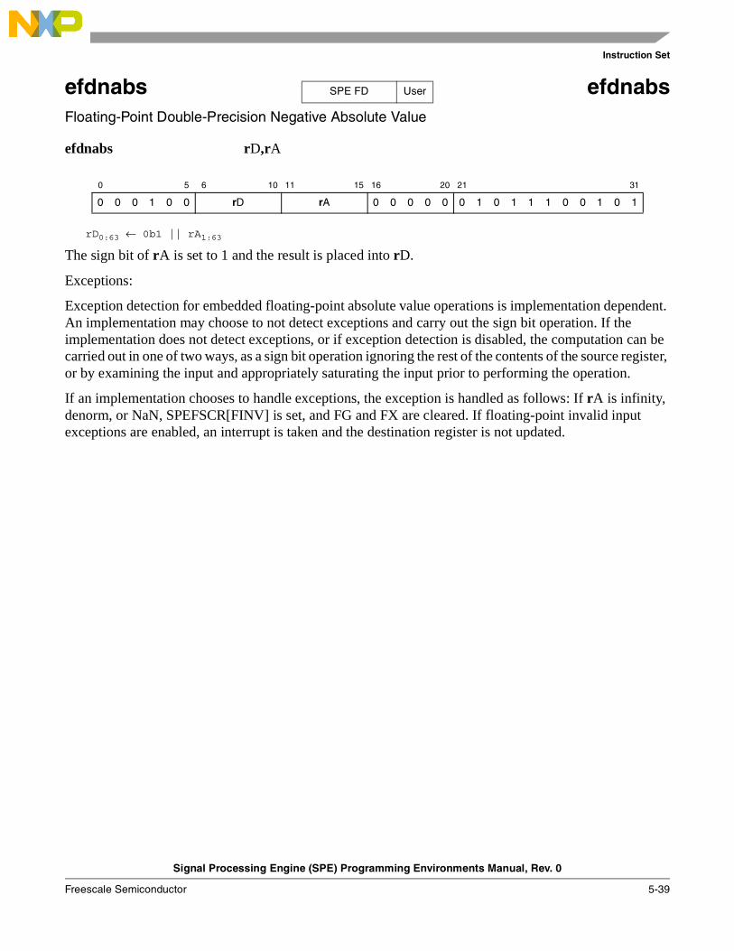
Instruction Set
Signal Processing Engine (SPE) Programming Environments Manual, Rev. 0
Freescale Semiconductor 5-39
efdnabs efdnabsFloating-Point Double-Precision Negative Absolute Value
efdnabs rD,rA
rD0:63 ← 0b1 || rA1:63
The sign bit of rA is set to 1 and the result is placed into rD.
Exceptions:
Exception detection for embedded floating-point absolute value operations is implementation dependent. An implementation may choose to not detect exceptions and carry out the sign bit operation. If the implementation does not detect exceptions, or if exception detection is disabled, the computation can be carried out in one of two ways, as a sign bit operation ignoring the rest of the contents of the source register, or by examining the input and appropriately saturating the input prior to performing the operation.
If an implementation chooses to handle exceptions, the exception is handled as follows: If rA is infinity, denorm, or NaN, SPEFSCR[FINV] is set, and FG and FX are cleared. If floating-point invalid input exceptions are enabled, an interrupt is taken and the destination register is not updated.
0 5 6 10 11 15 16 20 21 31
0 0 0 1 0 0 rD rA 0 0 0 0 0 0 1 0 1 1 1 0 0 1 0 1
SPE FD User
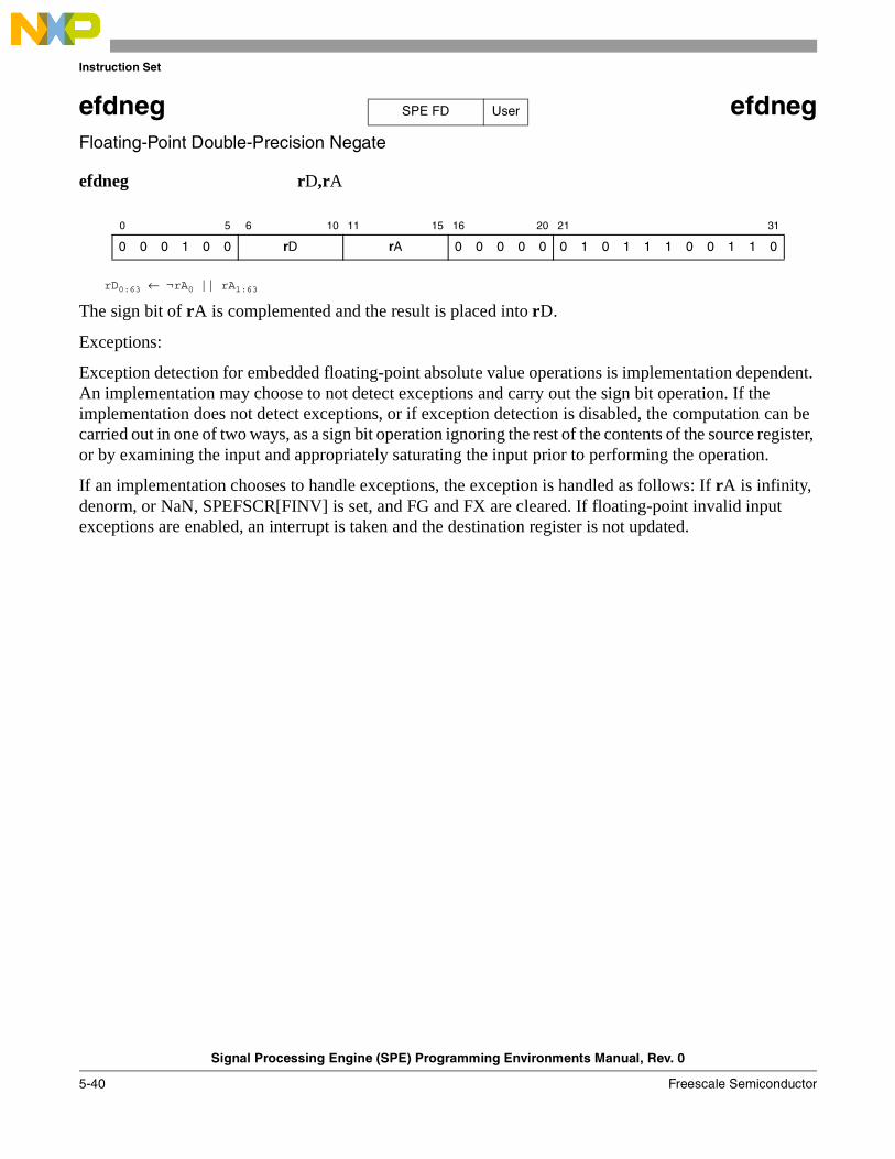
Instruction Set
Signal Processing Engine (SPE) Programming Environments Manual, Rev. 0
5-40 Freescale Semiconductor
efdneg efdnegFloating-Point Double-Precision Negate
efdneg rD,rA
rD0:63 ← ¬rA0 || rA1:63
The sign bit of rA is complemented and the result is placed into rD.
Exceptions:
Exception detection for embedded floating-point absolute value operations is implementation dependent. An implementation may choose to not detect exceptions and carry out the sign bit operation. If the implementation does not detect exceptions, or if exception detection is disabled, the computation can be carried out in one of two ways, as a sign bit operation ignoring the rest of the contents of the source register, or by examining the input and appropriately saturating the input prior to performing the operation.
If an implementation chooses to handle exceptions, the exception is handled as follows: If rA is infinity, denorm, or NaN, SPEFSCR[FINV] is set, and FG and FX are cleared. If floating-point invalid input exceptions are enabled, an interrupt is taken and the destination register is not updated.
0 5 6 10 11 15 16 20 21 31
0 0 0 1 0 0 rD rA 0 0 0 0 0 0 1 0 1 1 1 0 0 1 1 0
SPE FD User
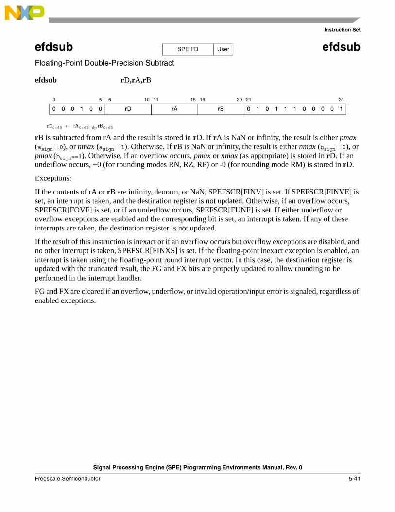
Instruction Set
Signal Processing Engine (SPE) Programming Environments Manual, Rev. 0
Freescale Semiconductor 5-41
efdsub efdsubFloating-Point Double-Precision Subtract
efdsub rD,rA,rB
rD0:63 ← rA0:63 -dp rB0:63
rB is subtracted from rA and the result is stored in rD. If rA is NaN or infinity, the result is either pmax (asign==0), or nmax (asign==1). Otherwise, If rB is NaN or infinity, the result is either nmax (bsign==0), or pmax (bsign==1). Otherwise, if an overflow occurs, pmax or nmax (as appropriate) is stored in rD. If an underflow occurs, +0 (for rounding modes RN, RZ, RP) or -0 (for rounding mode RM) is stored in rD.
Exceptions:
If the contents of rA or rB are infinity, denorm, or NaN, SPEFSCR[FINV] is set. If SPEFSCR[FINVE] is set, an interrupt is taken, and the destination register is not updated. Otherwise, if an overflow occurs, SPEFSCR[FOVF] is set, or if an underflow occurs, SPEFSCR[FUNF] is set. If either underflow or overflow exceptions are enabled and the corresponding bit is set, an interrupt is taken. If any of these interrupts are taken, the destination register is not updated.
If the result of this instruction is inexact or if an overflow occurs but overflow exceptions are disabled, and no other interrupt is taken, SPEFSCR[FINXS] is set. If the floating-point inexact exception is enabled, an interrupt is taken using the floating-point round interrupt vector. In this case, the destination register is updated with the truncated result, the FG and FX bits are properly updated to allow rounding to be performed in the interrupt handler.
FG and FX are cleared if an overflow, underflow, or invalid operation/input error is signaled, regardless of enabled exceptions.
0 5 6 10 11 15 16 20 21 31
0 0 0 1 0 0 rD rA rB 0 1 0 1 1 1 0 0 0 0 1
SPE FD User
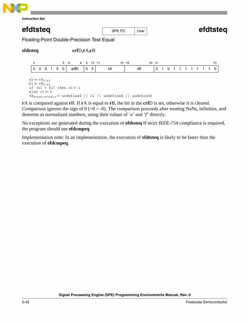
Instruction Set
Signal Processing Engine (SPE) Programming Environments Manual, Rev. 0
5-42 Freescale Semiconductor
efdtsteq efdtsteqFloating-Point Double-Precision Test Equal
efdtsteq crfD,rA,rB
al ← rA0:63bl ← rB0:63if (al = bl) then cl ← 1else cl ← 0CR4*crD:4*crD+3 ← undefined || cl || undefined || undefined
rA is compared against rB. If rA is equal to rB, the bit in the crfD is set, otherwise it is cleared. Comparison ignores the sign of 0 (+0 = -0). The comparison proceeds after treating NaNs, infinities, and denorms as normalized numbers, using their values of ‘e’ and ‘f’ directly.
No exceptions are generated during the execution of efdtsteq If strict IEEE-754 compliance is required, the program should use efdcmpeq.
Implementation note: In an implementation, the execution of efdtsteq is likely to be faster than the execution of efdcmpeq.
0 5 6 8 9 10 11 15 16 20 21 31
0 0 0 1 0 0 crfD 0 0 rA rB 0 1 0 1 1 1 1 1 1 1 0
SPE FD User
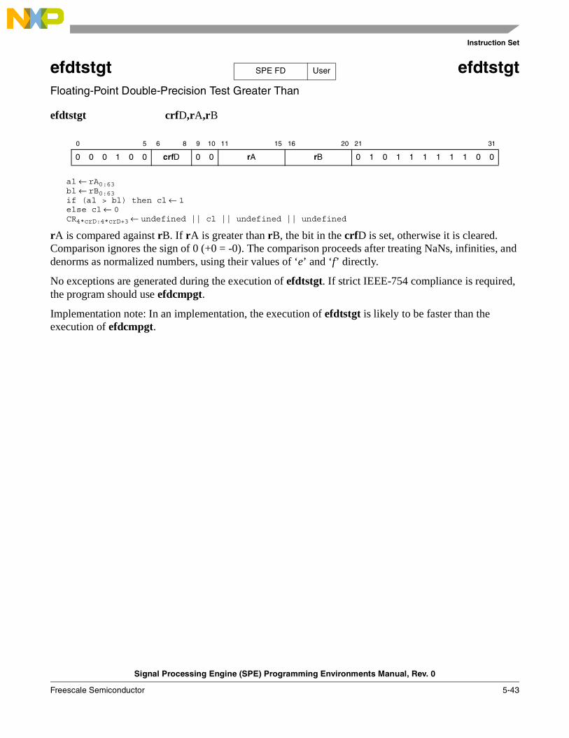
Instruction Set
Signal Processing Engine (SPE) Programming Environments Manual, Rev. 0
Freescale Semiconductor 5-43
efdtstgt efdtstgtFloating-Point Double-Precision Test Greater Than
efdtstgt crfD,rA,rB
al ← rA0:63bl ← rB0:63if (al > bl) then cl ← 1else cl ← 0CR4*crD:4*crD+3 ← undefined || cl || undefined || undefined
rA is compared against rB. If rA is greater than rB, the bit in the crfD is set, otherwise it is cleared. Comparison ignores the sign of 0 (+0 = -0). The comparison proceeds after treating NaNs, infinities, and denorms as normalized numbers, using their values of ‘e’ and ‘f’ directly.
No exceptions are generated during the execution of efdtstgt. If strict IEEE-754 compliance is required, the program should use efdcmpgt.
Implementation note: In an implementation, the execution of efdtstgt is likely to be faster than the execution of efdcmpgt.
0 5 6 8 9 10 11 15 16 20 21 31
0 0 0 1 0 0 crfD 0 0 rA rB 0 1 0 1 1 1 1 1 1 0 0
SPE FD User
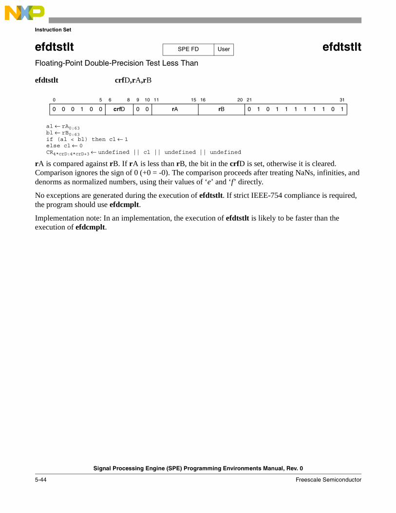
Instruction Set
Signal Processing Engine (SPE) Programming Environments Manual, Rev. 0
5-44 Freescale Semiconductor
efdtstlt efdtstltFloating-Point Double-Precision Test Less Than
efdtstlt crfD,rA,rB
al ← rA0:63bl ← rB0:63if (al < bl) then cl ← 1else cl ← 0CR4*crD:4*crD+3 ← undefined || cl || undefined || undefined
rA is compared against rB. If rA is less than rB, the bit in the crfD is set, otherwise it is cleared. Comparison ignores the sign of 0 (+0 = -0). The comparison proceeds after treating NaNs, infinities, and denorms as normalized numbers, using their values of ‘e’ and ‘f’ directly.
No exceptions are generated during the execution of efdtstlt. If strict IEEE-754 compliance is required, the program should use efdcmplt.
Implementation note: In an implementation, the execution of efdtstlt is likely to be faster than the execution of efdcmplt.
0 5 6 8 9 10 11 15 16 20 21 31
0 0 0 1 0 0 crfD 0 0 rA rB 0 1 0 1 1 1 1 1 1 0 1
SPE FD User
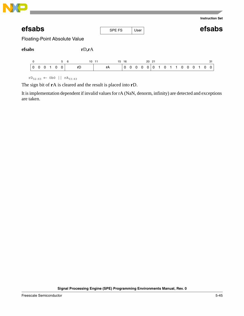
Instruction Set
Signal Processing Engine (SPE) Programming Environments Manual, Rev. 0
Freescale Semiconductor 5-45
efsabs efsabsFloating-Point Absolute Value
efsabs rD,rA
rD32:63 ← 0b0 || rA33:63
The sign bit of rA is cleared and the result is placed into rD.
It is implementation dependent if invalid values for rA (NaN, denorm, infinity) are detected and exceptions are taken.
0 5 6 10 11 15 16 20 21 31
0 0 0 1 0 0 rD rA 0 0 0 0 0 0 1 0 1 1 0 0 0 1 0 0
SPE FS User
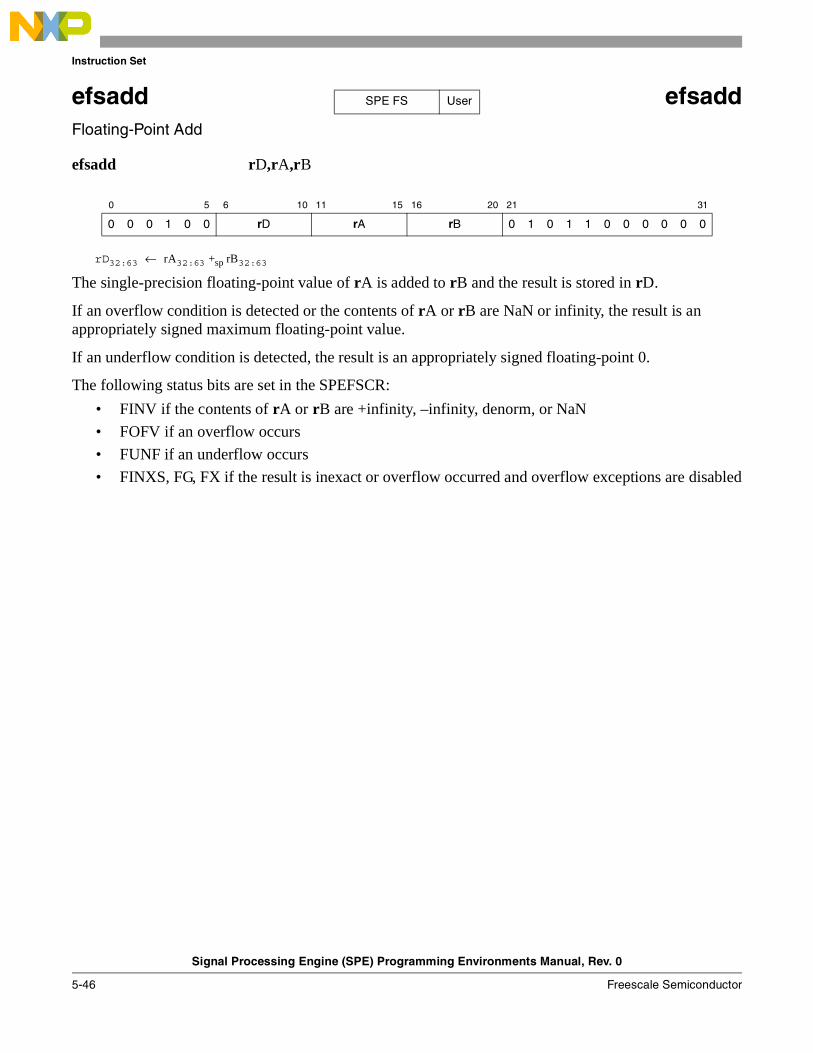
Instruction Set
Signal Processing Engine (SPE) Programming Environments Manual, Rev. 0
5-46 Freescale Semiconductor
efsadd efsaddFloating-Point Add
efsadd rD,rA,rB
rD32:63 ← rA32:63 +sp rB32:63
The single-precision floating-point value of rA is added to rB and the result is stored in rD.
If an overflow condition is detected or the contents of rA or rB are NaN or infinity, the result is an appropriately signed maximum floating-point value.
If an underflow condition is detected, the result is an appropriately signed floating-point 0.
The following status bits are set in the SPEFSCR:
• FINV if the contents of rA or rB are +infinity, –infinity, denorm, or NaN
• FOFV if an overflow occurs
• FUNF if an underflow occurs
• FINXS, FG, FX if the result is inexact or overflow occurred and overflow exceptions are disabled
0 5 6 10 11 15 16 20 21 31
0 0 0 1 0 0 rD rA rB 0 1 0 1 1 0 0 0 0 0 0
SPE FS User

Instruction Set
Signal Processing Engine (SPE) Programming Environments Manual, Rev. 0
Freescale Semiconductor 5-47
efscfsf efscfsfConvert Floating-Point from Signed Fraction
efscfsf rD,rB
rD32:63 ← CnvtI32ToFP32Sat(rB32:63, SIGN, LOWER, F)
The signed fractional value in rB is converted to the nearest single-precision floating-point value using the current rounding mode and placed into rD.
The following status bits are set in the SPEFSCR:
• FINXS, FG, FX if the result is inexact
0 5 6 10 11 15 16 20 21 31
0 0 0 1 0 0 rD 0 0 0 0 0 rB 0 1 0 1 1 0 1 0 0 1 1
SPE FS User

Instruction Set
Signal Processing Engine (SPE) Programming Environments Manual, Rev. 0
5-48 Freescale Semiconductor
efscfsi efscfsi Convert Floating-Point from Signed Integer
efscfsi rD,rB
rD32:63 ← CnvtSI32ToFP32Sat(rB32:63, SIGN, LOWER, I)
The signed integer value in rB is converted to the nearest single-precision floating-point value using the current rounding mode and placed into rD.
The following status bits are set in the SPEFSCR:
• FINXS, FG, FX if the result is inexact
0 5 6 10 11 15 16 20 21 31
0 0 0 1 0 0 rD 0 0 0 0 0 rB 0 1 0 1 1 0 1 0 0 0 1
SPE FS User

Instruction Set
Signal Processing Engine (SPE) Programming Environments Manual, Rev. 0
Freescale Semiconductor 5-49
efscfuf efscfufConvert Floating-Point from Unsigned Fraction
efscfuf rD,rB
rD32:63 ← CnvtI32ToFP32Sat(rB32:63, UNSIGN, LOWER, F)
The unsigned fractional value in rB is converted to the nearest single-precision floating-point value using the current rounding mode and placed into rD.
The following status bits are set in the SPEFSCR:
• FINXS, FG, FX if the result is inexact
0 5 6 10 11 15 16 20 21 31
0 0 0 1 0 0 rD 0 0 0 0 0 rB 0 1 0 1 1 0 1 0 0 1 0
SPE FS User

Instruction Set
Signal Processing Engine (SPE) Programming Environments Manual, Rev. 0
5-50 Freescale Semiconductor
efscfui efscfui Convert Floating-Point from Unsigned Integer
efscfui rD,rB
rD32:63 ← CnvtI32ToFP32Sat(rB32:63, UNSIGN, LOWER, I)
The unsigned integer value in rB is converted to the nearest single-precision floating-point value using the current rounding mode and placed into rD.
The following status bits are set in the SPEFSCR:
• FINXS, FG, FX if the result is inexact
0 5 6 10 11 15 16 20 21 31
0 0 0 1 0 0 rD 0 0 0 0 0 rB 0 1 0 1 1 0 1 0 0 0 0
SPE FS User
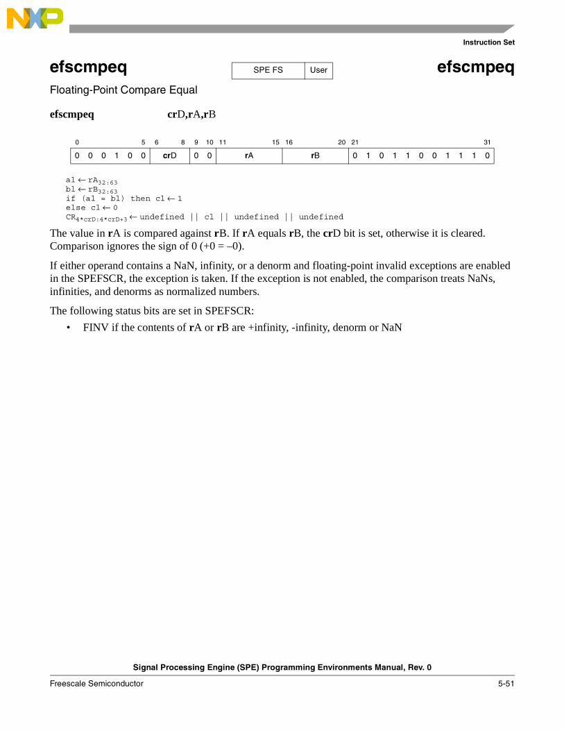
Instruction Set
Signal Processing Engine (SPE) Programming Environments Manual, Rev. 0
Freescale Semiconductor 5-51
efscmpeq efscmpeqFloating-Point Compare Equal
efscmpeq crD,rA,rB
al ← rA32:63bl ← rB32:63if (al = bl) then cl ← 1else cl ← 0CR4*crD:4*crD+3 ← undefined || cl || undefined || undefined
The value in rA is compared against rB. If rA equals rB, the crD bit is set, otherwise it is cleared. Comparison ignores the sign of 0 (+0 = –0).
If either operand contains a NaN, infinity, or a denorm and floating-point invalid exceptions are enabled in the SPEFSCR, the exception is taken. If the exception is not enabled, the comparison treats NaNs, infinities, and denorms as normalized numbers.
The following status bits are set in SPEFSCR:
• FINV if the contents of rA or rB are +infinity, -infinity, denorm or NaN
0 5 6 8 9 10 11 15 16 20 21 31
0 0 0 1 0 0 crD 0 0 rA rB 0 1 0 1 1 0 0 1 1 1 0
SPE FS User
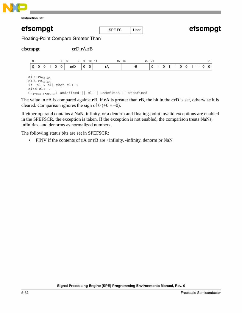
Instruction Set
Signal Processing Engine (SPE) Programming Environments Manual, Rev. 0
5-52 Freescale Semiconductor
efscmpgt efscmpgtFloating-Point Compare Greater Than
efscmpgt crD,rA,rB
al ← rA32:63bl ← rB32:63if (al > bl) then cl ← 1else cl ← 0CR4*crD:4*crD+3 ← undefined || cl || undefined || undefined
The value in rA is compared against rB. If rA is greater than rB, the bit in the crD is set, otherwise it is cleared. Comparison ignores the sign of 0 (+0 = –0).
If either operand contains a NaN, infinity, or a denorm and floating-point invalid exceptions are enabled in the SPEFSCR, the exception is taken. If the exception is not enabled, the comparison treats NaNs, infinities, and denorms as normalized numbers.
The following status bits are set in SPEFSCR:
• FINV if the contents of rA or rB are +infinity, -infinity, denorm or NaN
0 5 6 8 9 10 11 15 16 20 21 31
0 0 0 1 0 0 crD 0 0 rA rB 0 1 0 1 1 0 0 1 1 0 0
SPE FS User
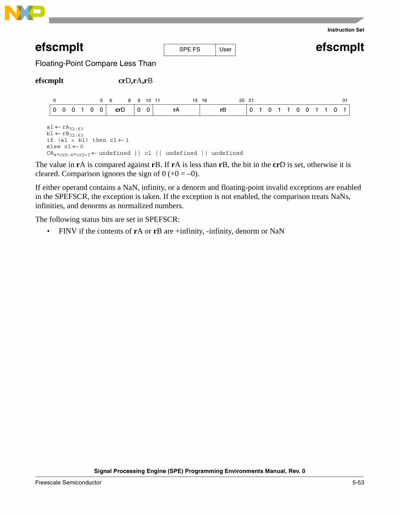
Instruction Set
Signal Processing Engine (SPE) Programming Environments Manual, Rev. 0
Freescale Semiconductor 5-53
efscmplt efscmpltFloating-Point Compare Less Than
efscmplt crD,rA,rB
al ← rA32:63bl ← rB32:63if (al < bl) then cl ← 1else cl ← 0CR4*crD:4*crD+3 ← undefined || cl || undefined || undefined
The value in rA is compared against rB. If rA is less than rB, the bit in the crD is set, otherwise it is cleared. Comparison ignores the sign of 0 (+0 = –0).
If either operand contains a NaN, infinity, or a denorm and floating-point invalid exceptions are enabled in the SPEFSCR, the exception is taken. If the exception is not enabled, the comparison treats NaNs, infinities, and denorms as normalized numbers.
The following status bits are set in SPEFSCR:
• FINV if the contents of rA or rB are +infinity, -infinity, denorm or NaN
0 5 6 8 9 10 11 15 16 20 21 31
0 0 0 1 0 0 crD 0 0 rA rB 0 1 0 1 1 0 0 1 1 0 1
SPE FS User

Instruction Set
Signal Processing Engine (SPE) Programming Environments Manual, Rev. 0
5-54 Freescale Semiconductor
efsctsf efsctsfConvert Floating-Point to Signed Fraction
efsctsf rD,rB
rD32:63 ← CnvtFP32ToISat(rB32:63, SIGN, LOWER, ROUND, F)
The single-precision floating-point value in rB is converted to a signed fraction using the current rounding mode. The result saturates if it cannot be represented in a 32-bit fraction. NaNs are converted to 0.
The following status bits are set in the SPEFSCR:
• FINV if the contents of rB are +infinity., –infinity, denorm, or NaN, or rB cannot be represented in the target format
• FINXS, FG, FX if the result is inexact
0 5 6 10 11 15 16 20 21 31
0 0 0 1 0 0 rD 0 0 0 0 0 rB 0 1 0 1 1 0 1 0 1 1 1
SPE FS User

Instruction Set
Signal Processing Engine (SPE) Programming Environments Manual, Rev. 0
Freescale Semiconductor 5-55
efsctsi efsctsi Convert Floating-Point to Signed Integer
efsctsi rD,rB
rD32:63 ← CnvtFP32ToISat(rB32:63, SIGN, LOWER, ROUND, I)
The single-precision floating-point value in rB is converted to a signed integer using the current rounding mode. The result saturates if it cannot be represented in a 32-bit integer. NaNs are converted to 0.
The following status bits are set in the SPEFSCR:
• FINV if the contents of rB are +infinity, -infinity, denorm, or NaN, or rB cannot be represented in the target format
• FINXS, FG, FX if the result is inexact
0 5 6 10 11 15 16 20 21 31
0 0 0 1 0 0 rD 0 0 0 0 0 rB 0 1 0 1 1 0 1 0 1 0 1
SPE FS User

Instruction Set
Signal Processing Engine (SPE) Programming Environments Manual, Rev. 0
5-56 Freescale Semiconductor
efsctsiz efsctsiz Convert Floating-Point to Signed Integer with Round toward Zero
efsctsiz rD,rB
rD32–63 ← CnvtFP32ToISat(rB32:63, SIGN, LOWER, TRUNC, I)
The single-precision floating-point value in rB is converted to a signed integer using the rounding mode Round towards Zero. The result saturates if it cannot be represented in a 32-bit integer. NaNs are converted to 0.
0 5 6 10 11 15 16 20 21 31
0 0 0 1 0 0 rD 0 0 0 0 0 rB 0 1 0 1 1 0 1 1 0 1 0
SPE FS User

Instruction Set
Signal Processing Engine (SPE) Programming Environments Manual, Rev. 0
Freescale Semiconductor 5-57
efsctuf efsctufConvert Floating-Point to Unsigned Fraction
efsctuf rD,rB
rD32:63 ← CnvtFP32ToISat(rB32:63, UNSIGN, LOWER, ROUND, F)
The single-precision floating-point value in rB is converted to an unsigned fraction using the current rounding mode. The result saturates if it cannot be represented in a 32-bit unsigned fraction. NaNs are converted to 0.
The following status bits are set in the SPEFSCR:
• FINV if the contents of rB are +infinity, –infinity, denorm, or NaN, or rB cannot be represented in the target format
• FINXS, FG, FX if the result is inexact
0 5 6 10 11 15 16 20 21 31
0 0 0 1 0 0 rD 0 0 0 0 0 rB 0 1 0 1 1 0 1 0 1 1 0
SPE FS User

Instruction Set
Signal Processing Engine (SPE) Programming Environments Manual, Rev. 0
5-58 Freescale Semiconductor
efsctui efsctui Convert Floating-Point to Unsigned Integer
efsctui rD,rB
rD32:63 ← CnvtFP32ToISat(rB32:63, UNSIGN, LOWER, ROUND, I)
The single-precision floating-point value in rB is converted to an unsigned integer using the current rounding mode. The result saturates if it cannot be represented in a 32-bit unsigned integer. NaNs are converted to 0.
The following status bits are set in the SPEFSCR:
• FINV if the contents of rB are +infinity, –infinity, denorm, or NaN, or rB cannot be represented in the target format
• FINXS, FG, FX if the result is inexact
0 5 6 10 11 15 16 20 21 31
0 0 0 1 0 0 rD 0 0 0 0 0 rB 0 1 0 1 1 0 1 0 1 0 0
SPE FS User

Instruction Set
Signal Processing Engine (SPE) Programming Environments Manual, Rev. 0
Freescale Semiconductor 5-59
efsctuiz efsctuiz Convert Floating-Point to Unsigned Integer with Round toward Zero
efsctuiz rD,rB
rD32:63 ← CnvtFP32ToISat(rB32:63, UNSIGN, LOWER, TRUNC, I)
The single-precision floating-point value in rB is converted to an unsigned integer using the rounding mode Round toward Zero. The result saturates if it cannot be represented in a 32-bit unsigned integer. NaNs are converted to 0.
The following status bits are set in the SPEFSCR:
• FINV if the contents of rB are +infinity, –infinity, denorm, or NaN, or rB cannot be represented in the target format
• FINXS, FG, FX if the result is inexact
0 5 6 10 11 15 16 20 21 31
0 0 0 1 0 0 rD 0 0 0 0 0 rB 0 1 0 1 1 0 1 1 0 0 0
SPE FS User

Instruction Set
Signal Processing Engine (SPE) Programming Environments Manual, Rev. 0
5-60 Freescale Semiconductor
efsdiv efsdivFloating-Point Divide
efsdiv rD,rA,rB
rD32:63 ← rA32:63 ÷sp rB32:63
The single-precision floating-point value in rA is divided by rB and the result is stored in rD.
If an overflow is detected, or rB is a denorm (or 0 value), or rA is a NaN or infinity and rB is a normalized number, the result is an appropriately signed maximum floating-point value.
If an underflow is detected or rB is a NaN or infinity, the result is an appropriately signed floating-point 0.
The following status bits are set in the SPEFSCR:
• FINV if the contents of rA or rB are +infinity, –infinity, denorm, or NaN
• FOFV if an overflow occurs
• FUNV if an underflow occurs
• FDBZS, FDBZ if a divide by zero occurs
• FINXS, FG, FX if the result is inexact or overflow occurred and overflow exceptions are disabled
0 5 6 10 11 15 16 20 21 31
0 0 0 1 0 0 rD rA rB 0 1 0 1 1 0 0 1 0 0 1
SPE FS User

Instruction Set
Signal Processing Engine (SPE) Programming Environments Manual, Rev. 0
Freescale Semiconductor 5-61
efsmul efsmulFloating-Point Multiply
efsmul rD,rA,rB
rD32:63 ← rA32:63 ×sp rB32:63
The single-precision floating-point value in rA is multiplied by rB and the result is stored in rD.
If an overflow is detected the result is an appropriately signed maximum floating-point value.
If one of rA or rB is a NaN or an infinity and the other is not a denorm or zero, the result is an appropriately signed maximum floating-point value.
If an underflow is detected, or rA or rB is a denorm, the result is an appropriately signed floating-point 0.
The following status bits are set in the SPEFSCR:
• FINV if the contents of rA or rB are +infinity, –infinity, denorm, or NaN
• FOFV if an overflow occurs
• FUNV if an underflow occurs
• FINXS, FG, FX if the result is inexact or overflow occurred and overflow exceptions are disabled
0 5 6 10 11 15 16 20 21 31
0 0 0 1 0 0 rD rA rB 0 1 0 1 1 0 0 1 0 0 0
SPE FS User
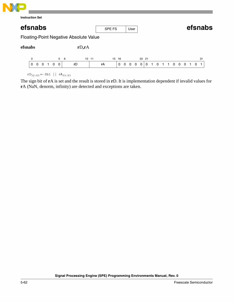
Instruction Set
Signal Processing Engine (SPE) Programming Environments Manual, Rev. 0
5-62 Freescale Semiconductor
efsnabs efsnabsFloating-Point Negative Absolute Value
efsnabs rD,rA
rD32:63 ← 0b1 || rA33:63
The sign bit of rA is set and the result is stored in rD. It is implementation dependent if invalid values for rA (NaN, denorm, infinity) are detected and exceptions are taken.
0 5 6 10 11 15 16 20 21 31
0 0 0 1 0 0 rD rA 0 0 0 0 0 0 1 0 1 1 0 0 0 1 0 1
SPE FS User

Instruction Set
Signal Processing Engine (SPE) Programming Environments Manual, Rev. 0
Freescale Semiconductor 5-63
efsneg efsnegFloating-Point Negate
efsneg rD,rA
rD32:63 ← ¬rA32 || rA33:63
The sign bit of rA is complemented and the result is stored in rD. It is implementation dependent if invalid values for rA (NaN, denorm, infinity) are detected and exceptions are taken.
0 5 6 10 11 15 16 20 21 31
0 0 0 1 0 0 rD rA 0 0 0 0 0 0 1 0 1 1 0 0 0 1 1 0
SPE FS User

Instruction Set
Signal Processing Engine (SPE) Programming Environments Manual, Rev. 0
5-64 Freescale Semiconductor
efssub efssubFloating-Point Subtract
efssub rD,rA,rB
rD32:63 ← rA32:63 -sp rB32:63
The single-precision floating-point value in rB is subtracted from that in rA and the result is stored in rD.
If an overflow condition is detected or the contents of rA or rB are NaN or infinity, the result is an appropriately signed maximum floating-point value.
If an underflow condition is detected, the result is an appropriately signed floating-point 0.
The following status bits are set in the SPEFSCR:
• FINV if the contents of rA or rB are +infinity, –infinity, denorm, or NaN
• FOFV if an overflow occurs
• FUNF if an underflow occurs
• FINXS, FG, FX if the result is inexact or overflow occurred and overflow exceptions are disabled
0 5 6 10 11 15 16 20 21 31
0 0 0 1 0 0 rD rA rB 0 1 0 1 1 0 0 0 0 0 1
SPE FS User
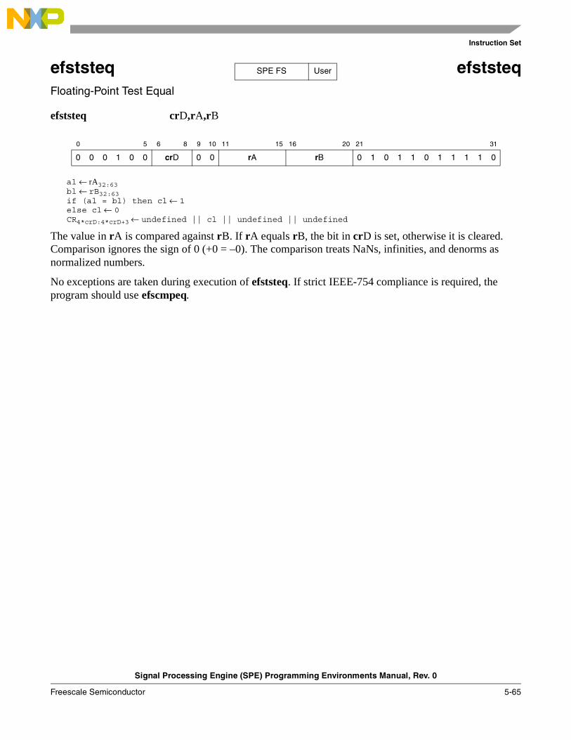
Instruction Set
Signal Processing Engine (SPE) Programming Environments Manual, Rev. 0
Freescale Semiconductor 5-65
efststeq efststeqFloating-Point Test Equal
efststeq crD,rA,rB
al ← rA32:63bl ← rB32:63if (al = bl) then cl ← 1else cl ← 0CR4*crD:4*crD+3 ← undefined || cl || undefined || undefined
The value in rA is compared against rB. If rA equals rB, the bit in crD is set, otherwise it is cleared. Comparison ignores the sign of 0 (+0 = –0). The comparison treats NaNs, infinities, and denorms as normalized numbers.
No exceptions are taken during execution of efststeq. If strict IEEE-754 compliance is required, the program should use efscmpeq.
0 5 6 8 9 10 11 15 16 20 21 31
0 0 0 1 0 0 crD 0 0 rA rB 0 1 0 1 1 0 1 1 1 1 0
SPE FS User
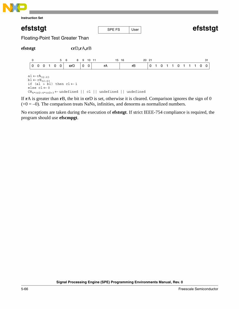
Instruction Set
Signal Processing Engine (SPE) Programming Environments Manual, Rev. 0
5-66 Freescale Semiconductor
efststgt efststgtFloating-Point Test Greater Than
efststgt crD,rA,rB
al ← rA32:63bl ← rB32:63if (al > bl) then cl ← 1else cl ← 0CR4*crD:4*crD+3 ← undefined || cl || undefined || undefined
If rA is greater than rB, the bit in crD is set, otherwise it is cleared. Comparison ignores the sign of 0 (+0 = –0). The comparison treats NaNs, infinities, and denorms as normalized numbers.
No exceptions are taken during the execution of efststgt. If strict IEEE-754 compliance is required, the program should use efscmpgt.
0 5 6 8 9 10 11 15 16 20 21 31
0 0 0 1 0 0 crD 0 0 rA rB 0 1 0 1 1 0 1 1 1 0 0
SPE FS User
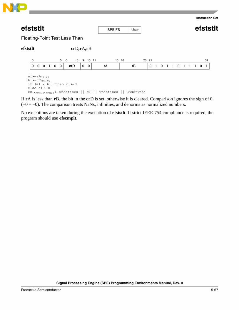
Instruction Set
Signal Processing Engine (SPE) Programming Environments Manual, Rev. 0
Freescale Semiconductor 5-67
efststlt efststltFloating-Point Test Less Than
efststlt crD,rA,rB
al ← rA32:63bl ← rB32:63if (al < bl) then cl ← 1else cl ← 0CR4*crD:4*crD+3 ← undefined || cl || undefined || undefined
If rA is less than rB, the bit in the crD is set, otherwise it is cleared. Comparison ignores the sign of 0 (+0 = –0). The comparison treats NaNs, infinities, and denorms as normalized numbers.
No exceptions are taken during the execution of efststlt. If strict IEEE-754 compliance is required, the program should use efscmplt.
0 5 6 8 9 10 11 15 16 20 21 31
0 0 0 1 0 0 crD 0 0 rA rB 0 1 0 1 1 0 1 1 1 0 1
SPE FS User
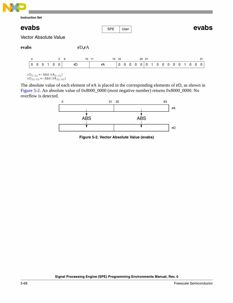
Instruction Set
Signal Processing Engine (SPE) Programming Environments Manual, Rev. 0
5-68 Freescale Semiconductor
evabs evabsVector Absolute Value
evabs rD,rA
rD0:31 ← ABS(rA0:31)rD32:63 ← ABS(rA32:63)
The absolute value of each element of rA is placed in the corresponding elements of rD, as shown in Figure 5-2. An absolute value of 0x8000_0000 (most negative number) returns 0x8000_0000. No overflow is detected.
Figure 5-2. Vector Absolute Value (evabs)
0 5 6 10 11 15 16 20 21 31
0 0 0 1 0 0 rD rA 0 0 0 0 0 0 1 0 0 0 0 0 1 0 0 0
SPE User
0 31 32 63
rA
rD
ABS ABS
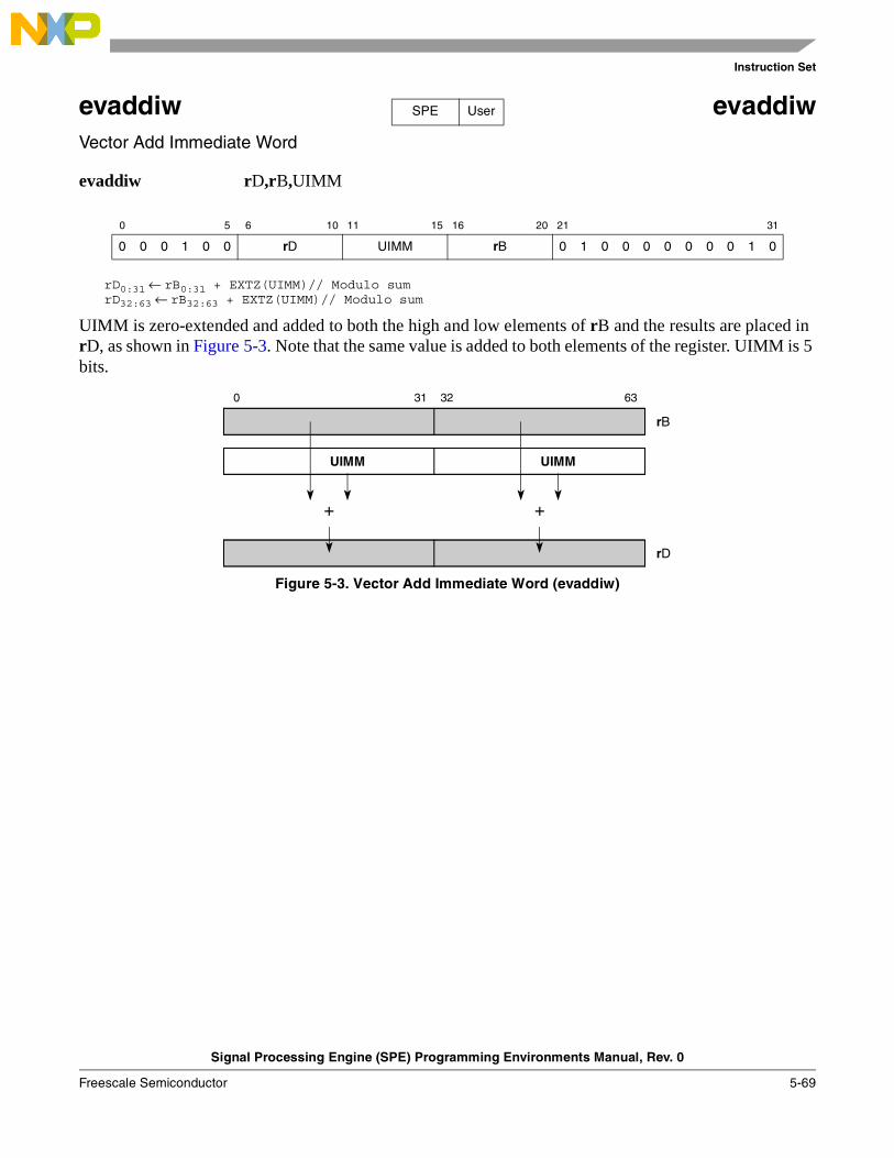
Instruction Set
Signal Processing Engine (SPE) Programming Environments Manual, Rev. 0
Freescale Semiconductor 5-69
evaddiw evaddiwVector Add Immediate Word
evaddiw rD,rB,UIMM
rD0:31 ← rB0:31 + EXTZ(UIMM)// Modulo sumrD32:63 ← rB32:63 + EXTZ(UIMM)// Modulo sum
UIMM is zero-extended and added to both the high and low elements of rB and the results are placed in rD, as shown in Figure 5-3. Note that the same value is added to both elements of the register. UIMM is 5 bits.
Figure 5-3. Vector Add Immediate Word (evaddiw)
0 5 6 10 11 15 16 20 21 31
0 0 0 1 0 0 rD UIMM rB 0 1 0 0 0 0 0 0 0 1 0
SPE User
0 31 32 63
rB
UIMM
+ +
rD
UIMM
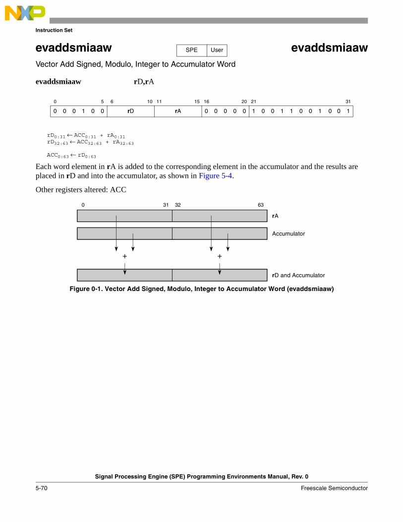
Instruction Set
Signal Processing Engine (SPE) Programming Environments Manual, Rev. 0
5-70 Freescale Semiconductor
evaddsmiaaw evaddsmiaawVector Add Signed, Modulo, Integer to Accumulator Word
evaddsmiaaw rD,rA
rD0:31 ← ACC0:31 + rA0:31rD32:63 ← ACC32:63 + rA32:63
ACC0:63 ← rD0:63
Each word element in rA is added to the corresponding element in the accumulator and the results are placed in rD and into the accumulator, as shown in Figure 5-4.
Other registers altered: ACC
Figure 0-1. Vector Add Signed, Modulo, Integer to Accumulator Word (evaddsmiaaw)
0 5 6 10 11 15 16 20 21 31
0 0 0 1 0 0 rD rA 0 0 0 0 0 1 0 0 1 1 0 0 1 0 0 1
SPE User
0 31 32 63
rA
Accumulator
+ +
rD and Accumulator
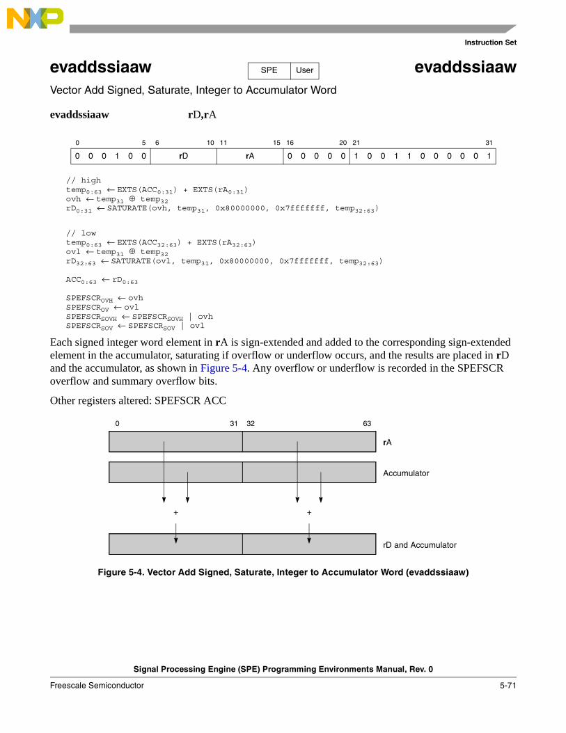
Instruction Set
Signal Processing Engine (SPE) Programming Environments Manual, Rev. 0
Freescale Semiconductor 5-71
evaddssiaaw evaddssiaawVector Add Signed, Saturate, Integer to Accumulator Word
evaddssiaaw rD,rA
// hightemp0:63 ← EXTS(ACC0:31) + EXTS(rA0:31)ovh ← temp31 ⊕ temp32rD0:31 ← SATURATE(ovh, temp31, 0x80000000, 0x7fffffff, temp32:63)
// lowtemp0:63 ← EXTS(ACC32:63) + EXTS(rA32:63)ovl ← temp31 ⊕ temp32rD32:63 ← SATURATE(ovl, temp31, 0x80000000, 0x7fffffff, temp32:63)
ACC0:63 ← rD0:63
SPEFSCROVH ← ovhSPEFSCROV ← ovlSPEFSCRSOVH ← SPEFSCRSOVH | ovhSPEFSCRSOV ← SPEFSCRSOV | ovl
Each signed integer word element in rA is sign-extended and added to the corresponding sign-extended element in the accumulator, saturating if overflow or underflow occurs, and the results are placed in rD and the accumulator, as shown in Figure 5-4. Any overflow or underflow is recorded in the SPEFSCR overflow and summary overflow bits.
Other registers altered: SPEFSCR ACC
Figure 5-4. Vector Add Signed, Saturate, Integer to Accumulator Word (evaddssiaaw)
0 5 6 10 11 15 16 20 21 31
0 0 0 1 0 0 rD rA 0 0 0 0 0 1 0 0 1 1 0 0 0 0 0 1
SPE User
0 31 32 63
rA
Accumulator
+ +
rD and Accumulator
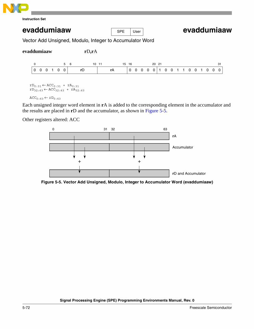
Instruction Set
Signal Processing Engine (SPE) Programming Environments Manual, Rev. 0
5-72 Freescale Semiconductor
evaddumiaaw evaddumiaawVector Add Unsigned, Modulo, Integer to Accumulator Word
evaddumiaaw rD,rA
rD0:31 ← ACC0:31 + rA0:31rD32:63 ← ACC32:63 + rA32:63
ACC0:63 ← rD0:63
Each unsigned integer word element in rA is added to the corresponding element in the accumulator and the results are placed in rD and the accumulator, as shown in Figure 5-5.
Other registers altered: ACC
Figure 5-5. Vector Add Unsigned, Modulo, Integer to Accumulator Word (evaddumiaaw)
0 5 6 10 11 15 16 20 21 31
0 0 0 1 0 0 rD rA 0 0 0 0 0 1 0 0 1 1 0 0 1 0 0 0
SPE User
0 31 32 63
rA
Accumulator
+ +
rD and Accumulator
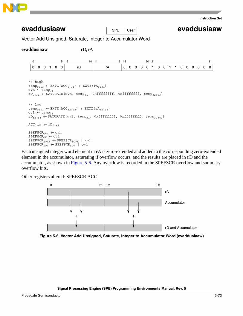
Instruction Set
Signal Processing Engine (SPE) Programming Environments Manual, Rev. 0
Freescale Semiconductor 5-73
evaddusiaaw evaddusiaawVector Add Unsigned, Saturate, Integer to Accumulator Word
evaddusiaaw rD,rA
// hightemp0:63 ← EXTZ(ACC0:31) + EXTZ(rA0:31)ovh ← temp31rD0:31 ← SATURATE(ovh, temp31, 0xffffffff, 0xffffffff, temp32:63)
// lowtemp0:63 ← EXTZ(ACC32:63) + EXTZ(rA32:63)ovl ← temp31rD32:63 ← SATURATE(ovl, temp31, 0xffffffff, 0xffffffff, temp32:63)
ACC0:63 ← rD0:63
SPEFSCROVH ← ovhSPEFSCROV ← ovlSPEFSCRSOVH ← SPEFSCRSOVH | ovhSPEFSCRSOV ← SPEFSCRSOV | ovl
Each unsigned integer word element in rA is zero-extended and added to the corresponding zero-extended element in the accumulator, saturating if overflow occurs, and the results are placed in rD and the accumulator, as shown in Figure 5-6. Any overflow is recorded in the SPEFSCR overflow and summary overflow bits.
Other registers altered: SPEFSCR ACC
Figure 5-6. Vector Add Unsigned, Saturate, Integer to Accumulator Word (evaddusiaaw)
0 5 6 10 11 15 16 20 21 31
0 0 0 1 0 0 rD rA 0 0 0 0 0 1 0 0 1 1 0 0 0 0 0 0
SPE User
0 31 32 63
rA
Accumulator
+ +
rD and Accumulator
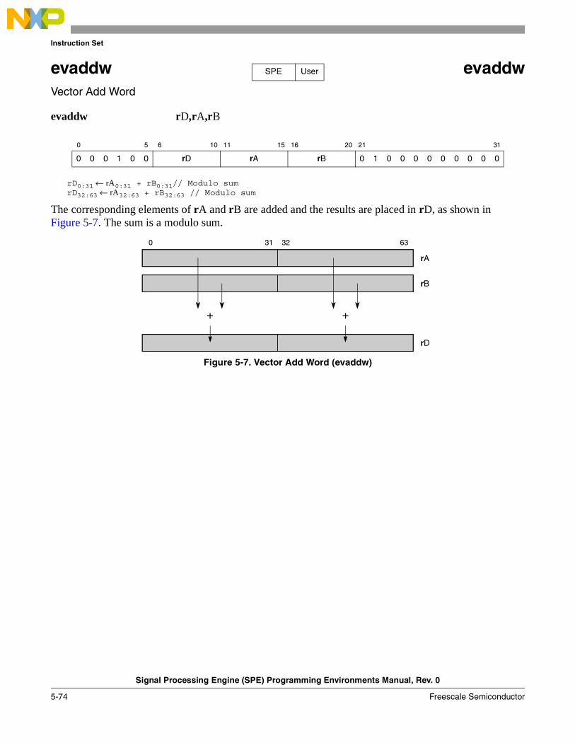
Instruction Set
Signal Processing Engine (SPE) Programming Environments Manual, Rev. 0
5-74 Freescale Semiconductor
evaddw evaddwVector Add Word
evaddw rD,rA,rB
rD0:31 ← rA0:31 + rB0:31// Modulo sumrD32:63 ← rA32:63 + rB32:63 // Modulo sum
The corresponding elements of rA and rB are added and the results are placed in rD, as shown in Figure 5-7. The sum is a modulo sum.
Figure 5-7. Vector Add Word (evaddw)
0 5 6 10 11 15 16 20 21 31
0 0 0 1 0 0 rD rA rB 0 1 0 0 0 0 0 0 0 0 0
SPE User
0 31 32 63
rA
rB
+ +
rD
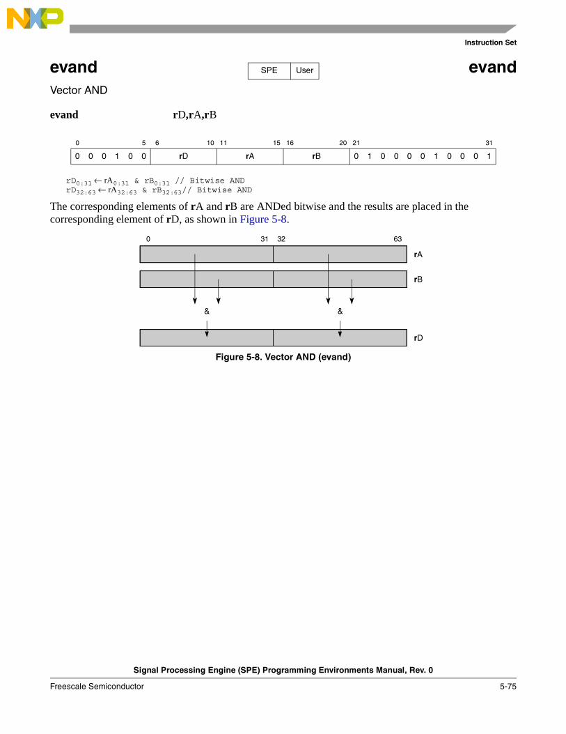
Instruction Set
Signal Processing Engine (SPE) Programming Environments Manual, Rev. 0
Freescale Semiconductor 5-75
evand evandVector AND
evand rD,rA,rB
rD0:31 ← rA0:31 & rB0:31 // Bitwise ANDrD32:63 ← rA32:63 & rB32:63// Bitwise AND
The corresponding elements of rA and rB are ANDed bitwise and the results are placed in the corresponding element of rD, as shown in Figure 5-8.
Figure 5-8. Vector AND (evand)
0 5 6 10 11 15 16 20 21 31
0 0 0 1 0 0 rD rA rB 0 1 0 0 0 0 1 0 0 0 1
SPE User
0 31 32 63
rA
rB
& &
rD
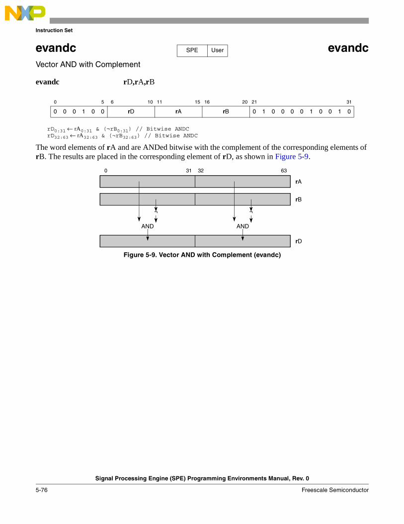
Instruction Set
Signal Processing Engine (SPE) Programming Environments Manual, Rev. 0
5-76 Freescale Semiconductor
evandc evandcVector AND with Complement
evandc rD,rA,rB
rD0:31 ← rA0:31 & (¬rB0:31) // Bitwise ANDCrD32:63 ← rA32:63 & (¬rB32:63) // Bitwise ANDC
The word elements of rA and are ANDed bitwise with the complement of the corresponding elements of rB. The results are placed in the corresponding element of rD, as shown in Figure 5-9.
Figure 5-9. Vector AND with Complement (evandc)
0 5 6 10 11 15 16 20 21 31
0 0 0 1 0 0 rD rA rB 0 1 0 0 0 0 1 0 0 1 0
SPE User
0 31 32 63
rA
rB
AND AND
rD
¬¬
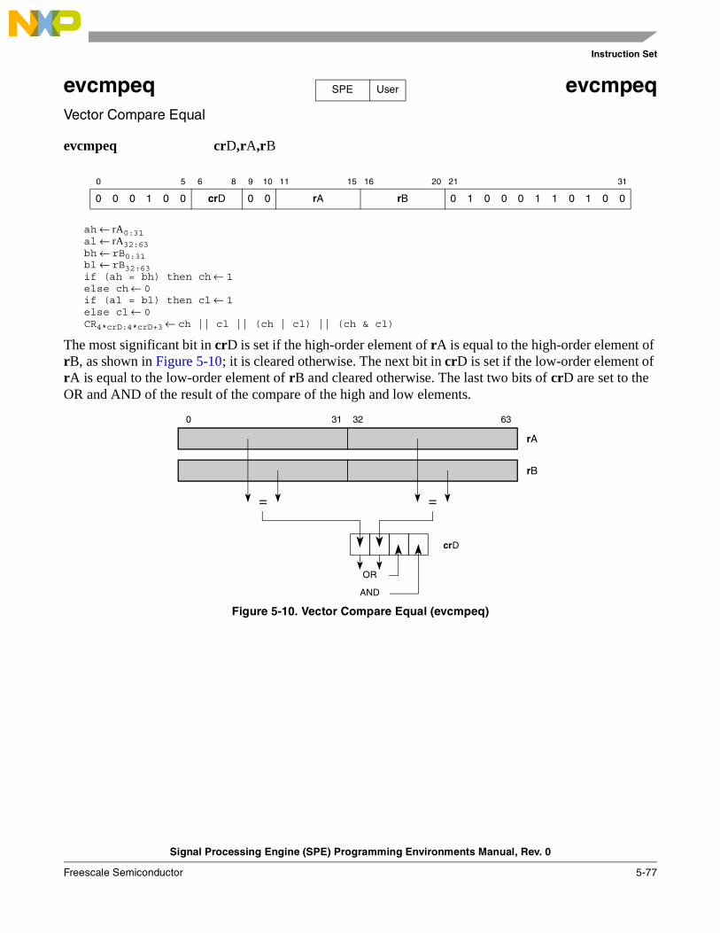
Instruction Set
Signal Processing Engine (SPE) Programming Environments Manual, Rev. 0
Freescale Semiconductor 5-77
evcmpeq evcmpeqVector Compare Equal
evcmpeq crD,rA,rB
ah ← rA0:31al ← rA32:63bh ← rB0:31bl ← rB32:63if (ah = bh) then ch ← 1else ch ← 0if (al = bl) then cl ← 1else cl ← 0CR4*crD:4*crD+3 ← ch || cl || (ch | cl) || (ch & cl)
The most significant bit in crD is set if the high-order element of rA is equal to the high-order element of rB, as shown in Figure 5-10; it is cleared otherwise. The next bit in crD is set if the low-order element of rA is equal to the low-order element of rB and cleared otherwise. The last two bits of crD are set to the OR and AND of the result of the compare of the high and low elements.
Figure 5-10. Vector Compare Equal (evcmpeq)
0 5 6 8 9 10 11 15 16 20 21 31
0 0 0 1 0 0 crD 0 0 rA rB 0 1 0 0 0 1 1 0 1 0 0
SPE User
0 31 32 63
rA
rB
= =
crD
OR
AND
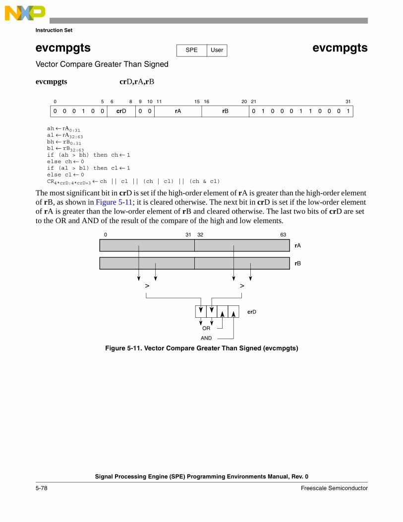
Instruction Set
Signal Processing Engine (SPE) Programming Environments Manual, Rev. 0
5-78 Freescale Semiconductor
evcmpgts evcmpgtsVector Compare Greater Than Signed
evcmpgts crD,rA,rB
ah ← rA0:31al ← rA32:63bh ← rB0:31bl ← rB32:63if (ah > bh) then ch ← 1else ch ← 0if (al > bl) then cl ← 1else cl ← 0CR4*crD:4*crD+3 ← ch || cl || (ch | cl) || (ch & cl)
The most significant bit in crD is set if the high-order element of rA is greater than the high-order element of rB, as shown in Figure 5-11; it is cleared otherwise. The next bit in crD is set if the low-order element of rA is greater than the low-order element of rB and cleared otherwise. The last two bits of crD are set to the OR and AND of the result of the compare of the high and low elements.
Figure 5-11. Vector Compare Greater Than Signed (evcmpgts)
0 5 6 8 9 10 11 15 16 20 21 31
0 0 0 1 0 0 crD 0 0 rA rB 0 1 0 0 0 1 1 0 0 0 1
SPE User
0 31 32 63
rA
rB
> >
crD
OR
AND
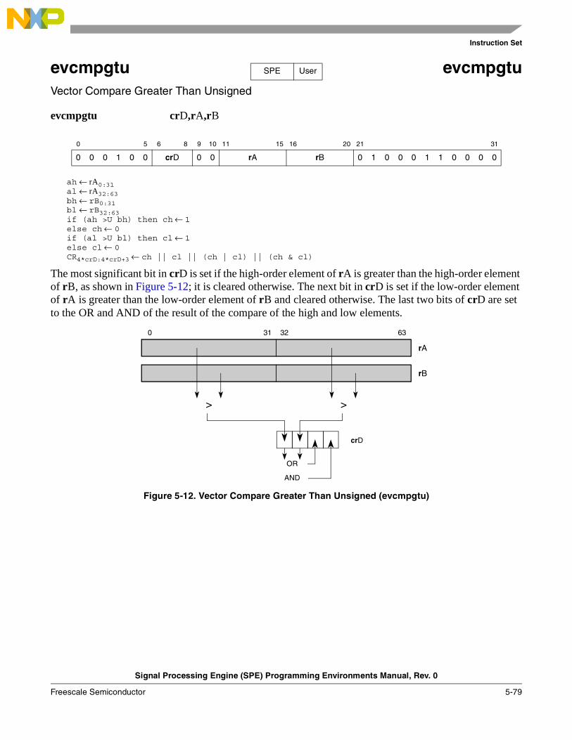
Instruction Set
Signal Processing Engine (SPE) Programming Environments Manual, Rev. 0
Freescale Semiconductor 5-79
evcmpgtu evcmpgtuVector Compare Greater Than Unsigned
evcmpgtu crD,rA,rB
ah ← rA0:31al ← rA32:63bh ← rB0:31bl ← rB32:63if (ah >U bh) then ch ← 1else ch ← 0if (al >U bl) then cl ← 1else cl ← 0CR4*crD:4*crD+3 ← ch || cl || (ch | cl) || (ch & cl)
The most significant bit in crD is set if the high-order element of rA is greater than the high-order element of rB, as shown in Figure 5-12; it is cleared otherwise. The next bit in crD is set if the low-order element of rA is greater than the low-order element of rB and cleared otherwise. The last two bits of crD are set to the OR and AND of the result of the compare of the high and low elements.
Figure 5-12. Vector Compare Greater Than Unsigned (evcmpgtu)
0 5 6 8 9 10 11 15 16 20 21 31
0 0 0 1 0 0 crD 0 0 rA rB 0 1 0 0 0 1 1 0 0 0 0
SPE User
0 31 32 63
rA
rB
> >
crD
OR
AND
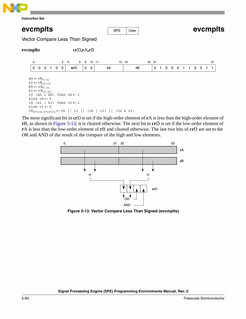
Instruction Set
Signal Processing Engine (SPE) Programming Environments Manual, Rev. 0
5-80 Freescale Semiconductor
evcmplts evcmpltsVector Compare Less Than Signed
evcmplts crD,rA,rB
ah ← rA0:31al ← rA32:63bh ← rB0:31bl ← rB32:63if (ah < bh) then ch ← 1else ch ← 0if (al < bl) then cl ← 1else cl ← 0CR4*crD:4*crD+3 ← ch || cl || (ch | cl) || (ch & cl)
The most significant bit in crD is set if the high-order element of rA is less than the high-order element of rB, as shown in Figure 5-13; it is cleared otherwise. The next bit in crD is set if the low-order element of rA is less than the low-order element of rB and cleared otherwise. The last two bits of crD are set to the OR and AND of the result of the compare of the high and low elements.
Figure 5-13. Vector Compare Less Than Signed (evcmplts)
0 5 6 8 9 10 11 15 16 20 21 31
0 0 0 1 0 0 crD 0 0 rA rB 0 1 0 0 0 1 1 0 0 1 1
SPE User
0 31 32 63
rA
rB
< <
crD
OR
AND
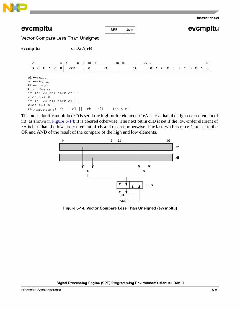
Instruction Set
Signal Processing Engine (SPE) Programming Environments Manual, Rev. 0
Freescale Semiconductor 5-81
evcmpltu evcmpltuVector Compare Less Than Unsigned
evcmpltu crD,rA,rB
ah ← rA0:31al ← rA32:63bh ← rB0:31bl ← rB32:63if (ah <U bh) then ch ← 1else ch ← 0if (al <U bl) then cl ← 1else cl ← 0CR4*crD:4*crD+3 ← ch || cl || (ch | cl) || (ch & cl)
The most significant bit in crD is set if the high-order element of rA is less than the high-order element of rB, as shown in Figure 5-14; it is cleared otherwise. The next bit in crD is set if the low-order element of rA is less than the low-order element of rB and cleared otherwise. The last two bits of crD are set to the OR and AND of the result of the compare of the high and low elements.
Figure 5-14. Vector Compare Less Than Unsigned (evcmpltu)
0 5 6 8 9 10 11 15 16 20 21 31
0 0 0 1 0 0 crD 0 0 rA rB 0 1 0 0 0 1 1 0 0 1 0
SPE User
0 31 32 63
rA
rB
< <
crD
OR
AND
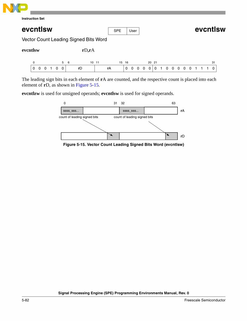
Instruction Set
Signal Processing Engine (SPE) Programming Environments Manual, Rev. 0
5-82 Freescale Semiconductor
evcntlsw evcntlswVector Count Leading Signed Bits Word
evcntlsw rD,rA
The leading sign bits in each element of rA are counted, and the respective count is placed into each element of rD, as shown in Figure 5-15.
evcntlzw is used for unsigned operands; evcntlsw is used for signed operands.
Figure 5-15. Vector Count Leading Signed Bits Word (evcntlsw)
0 5 6 10 11 15 16 20 21 31
0 0 0 1 0 0 rD rA 0 0 0 0 0 0 1 0 0 0 0 0 1 1 1 0
SPE User
0 31 32 63
rA
rD
ssss_sss... ssss_sss...
count of leading signed bits count of leading signed bits
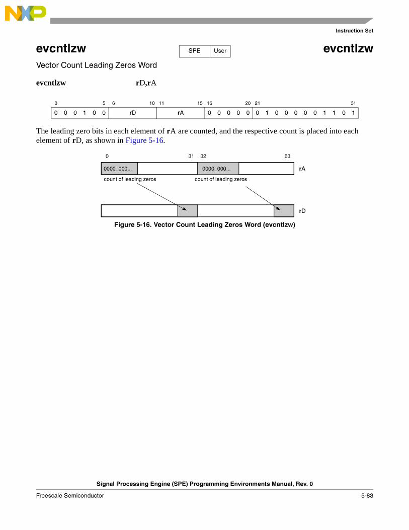
Instruction Set
Signal Processing Engine (SPE) Programming Environments Manual, Rev. 0
Freescale Semiconductor 5-83
evcntlzw evcntlzwVector Count Leading Zeros Word
evcntlzw rD,rA
The leading zero bits in each element of rA are counted, and the respective count is placed into each element of rD, as shown in Figure 5-16.
Figure 5-16. Vector Count Leading Zeros Word (evcntlzw)
0 5 6 10 11 15 16 20 21 31
0 0 0 1 0 0 rD rA 0 0 0 0 0 0 1 0 0 0 0 0 1 1 0 1
SPE User
0 31 32 63
rA
rD
0000_000... 0000_000...
count of leading zeros count of leading zeros
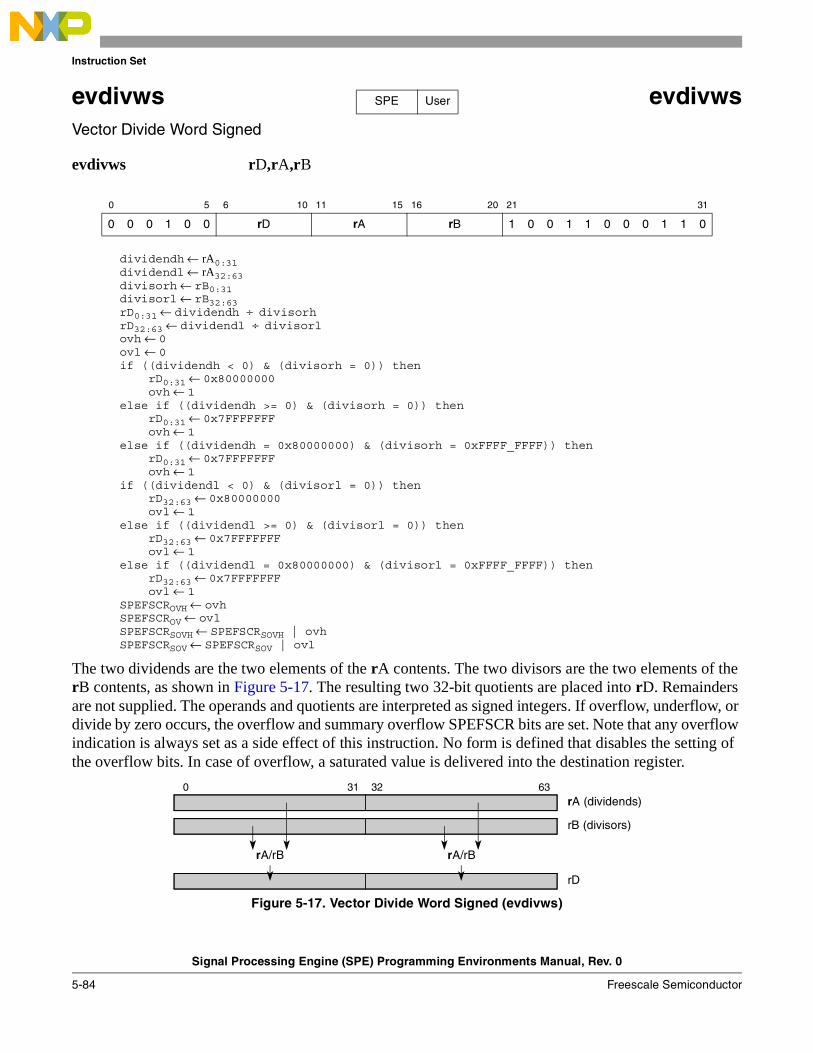
Instruction Set
Signal Processing Engine (SPE) Programming Environments Manual, Rev. 0
5-84 Freescale Semiconductor
evdivws evdivwsVector Divide Word Signed
evdivws rD,rA,rB
dividendh ← rA0:31dividendl ← rA32:63divisorh ← rB0:31divisorl ← rB32:63rD0:31 ← dividendh ÷ divisorhrD32:63 ← dividendl ÷ divisorlovh ← 0ovl ← 0if ((dividendh < 0) & (divisorh = 0)) then
rD0:31 ← 0x80000000ovh ← 1
else if ((dividendh >= 0) & (divisorh = 0)) thenrD0:31 ← 0x7FFFFFFFovh ← 1
else if ((dividendh = 0x80000000) & (divisorh = 0xFFFF_FFFF)) thenrD0:31 ← 0x7FFFFFFFovh ← 1
if ((dividendl < 0) & (divisorl = 0)) thenrD32:63 ← 0x80000000ovl ← 1
else if ((dividendl >= 0) & (divisorl = 0)) thenrD32:63 ← 0x7FFFFFFFovl ← 1
else if ((dividendl = 0x80000000) & (divisorl = 0xFFFF_FFFF)) thenrD32:63 ← 0x7FFFFFFFovl ← 1
SPEFSCROVH ← ovhSPEFSCROV ← ovlSPEFSCRSOVH ← SPEFSCRSOVH | ovhSPEFSCRSOV ← SPEFSCRSOV | ovl
The two dividends are the two elements of the rA contents. The two divisors are the two elements of the rB contents, as shown in Figure 5-17. The resulting two 32-bit quotients are placed into rD. Remainders are not supplied. The operands and quotients are interpreted as signed integers. If overflow, underflow, or divide by zero occurs, the overflow and summary overflow SPEFSCR bits are set. Note that any overflow indication is always set as a side effect of this instruction. No form is defined that disables the setting of the overflow bits. In case of overflow, a saturated value is delivered into the destination register.
Figure 5-17. Vector Divide Word Signed (evdivws)
0 5 6 10 11 15 16 20 21 31
0 0 0 1 0 0 rD rA rB 1 0 0 1 1 0 0 0 1 1 0
SPE User
0 31 32 63rA (dividends)
rB (divisors)
rA/rB rA/rB
rD
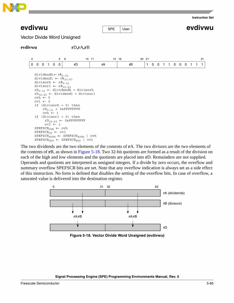
Instruction Set
Signal Processing Engine (SPE) Programming Environments Manual, Rev. 0
Freescale Semiconductor 5-85
evdivwu evdivwuVector Divide Word Unsigned
evdivwu rD,rA,rB
dividendh ← rA0:31dividendl ← rA32:63divisorh ← rB0:31divisorl ← rB32:63rD0:31 ← dividendh ÷ divisorhrD32:63 ← dividendl ÷ divisorlovh ← 0ovl ← 0if (divisorh = 0) then
rD0:31 = 0xFFFFFFFFovh ← 1
if (divisorl = 0) thenrD32:63 ← 0xFFFFFFFFovl ← 1
SPEFSCROVH ← ovhSPEFSCROV ← ovlSPEFSCRSOVH ← SPEFSCRSOVH | ovhSPEFSCRSOV ← SPEFSCRSOV | ovl
The two dividends are the two elements of the contents of rA. The two divisors are the two elements of the contents of rB, as shown in Figure 5-18. Two 32-bit quotients are formed as a result of the division on each of the high and low elements and the quotients are placed into rD. Remainders are not supplied. Operands and quotients are interpreted as unsigned integers. If a divide by zero occurs, the overflow and summary overflow SPEFSCR bits are set. Note that any overflow indication is always set as a side effect of this instruction. No form is defined that disables the setting of the overflow bits. In case of overflow, a saturated value is delivered into the destination register.
Figure 5-18. Vector Divide Word Unsigned (evdivwu)
0 5 6 10 11 15 16 20 21 31
0 0 0 1 0 0 rD rA rB 1 0 0 1 1 0 0 0 1 1 1
SPE User
0 31 32 63
rA (dividends)
rB (divisors)
rA/rB rA/rB
rD
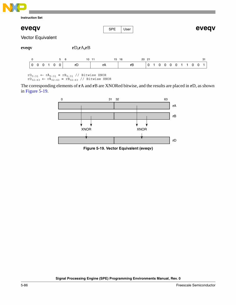
Instruction Set
Signal Processing Engine (SPE) Programming Environments Manual, Rev. 0
5-86 Freescale Semiconductor
eveqv eveqvVector Equivalent
eveqv rD,rA,rB
rD0:31 ← rA0:31 ≡ rB0:31 // Bitwise XNORrD32:63 ← rA32:63 ≡ rB32:63 // Bitwise XNOR
The corresponding elements of rA and rB are XNORed bitwise, and the results are placed in rD, as shown in Figure 5-19.
Figure 5-19. Vector Equivalent (eveqv)
0 5 6 10 11 15 16 20 21 31
0 0 0 1 0 0 rD rA rB 0 1 0 0 0 0 1 1 0 0 1
SPE User
0 31 32 63
rA
rB
XNOR XNOR
rD
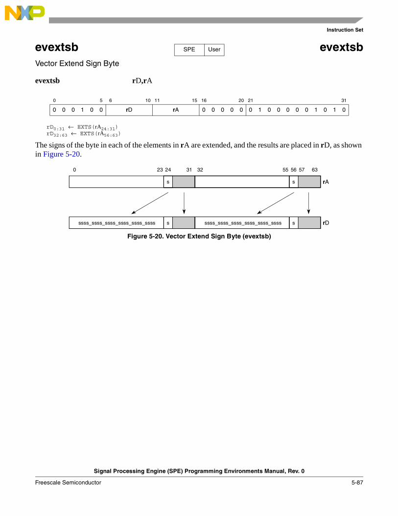
Instruction Set
Signal Processing Engine (SPE) Programming Environments Manual, Rev. 0
Freescale Semiconductor 5-87
evextsb evextsbVector Extend Sign Byte
evextsb rD,rA
rD0:31 ← EXTS(rA24:31)rD32:63 ← EXTS(rA56:63)
The signs of the byte in each of the elements in rA are extended, and the results are placed in rD, as shown in Figure 5-20.
Figure 5-20. Vector Extend Sign Byte (evextsb)
0 5 6 10 11 15 16 20 21 31
0 0 0 1 0 0 rD rA 0 0 0 0 0 0 1 0 0 0 0 0 1 0 1 0
SPE User
0 31 32 63
rA
rD
s
23 24 55 56 57
s
s sssss_ssss_ssss_ssss_ssss_ssss ssss_ssss_ssss_ssss_ssss_ssss
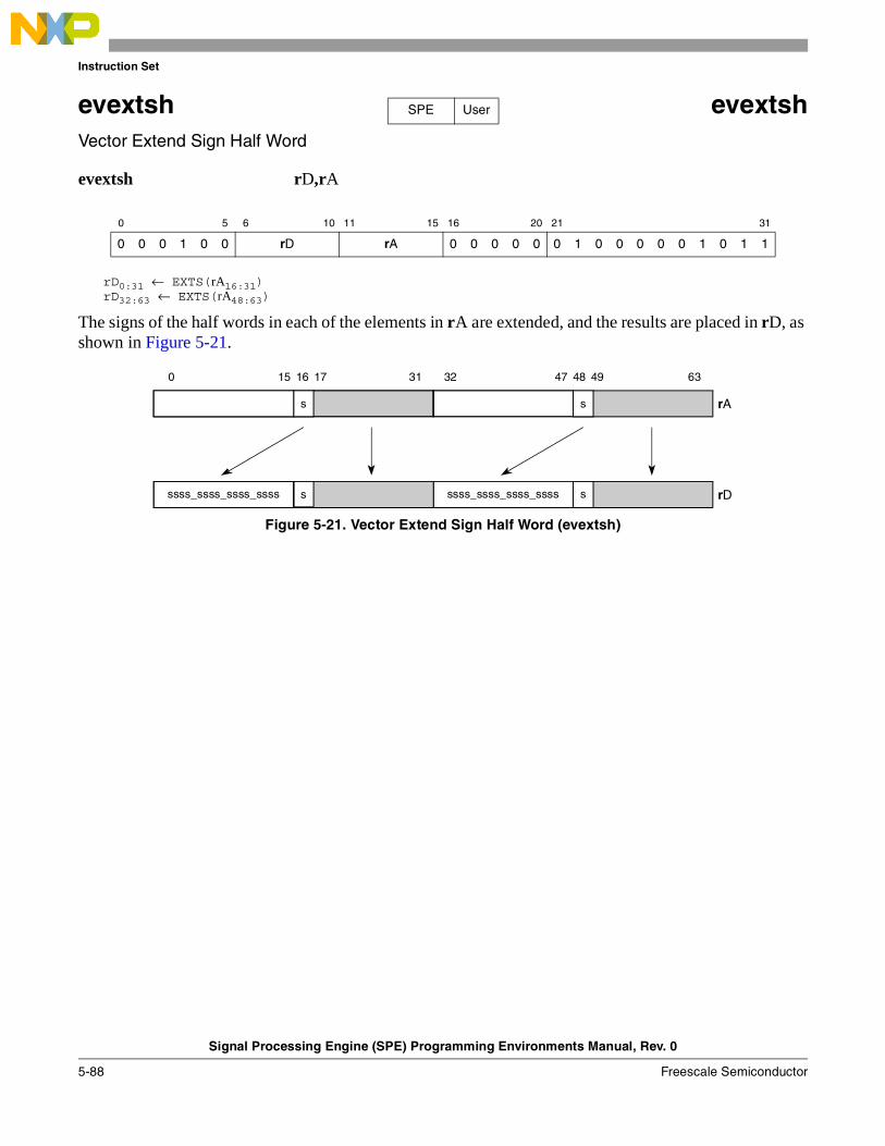
Instruction Set
Signal Processing Engine (SPE) Programming Environments Manual, Rev. 0
5-88 Freescale Semiconductor
evextsh evextshVector Extend Sign Half Word
evextsh rD,rA
rD0:31 ← EXTS(rA16:31)rD32:63 ← EXTS(rA48:63)
The signs of the half words in each of the elements in rA are extended, and the results are placed in rD, as shown in Figure 5-21.
Figure 5-21. Vector Extend Sign Half Word (evextsh)
0 5 6 10 11 15 16 20 21 31
0 0 0 1 0 0 rD rA 0 0 0 0 0 0 1 0 0 0 0 0 1 0 1 1
SPE User
0 31 32 63
rA
rD
ss
ss ssss_ssss_ssss_ssssssss_ssss_ssss_ssss
15 16 17 47 48 49
Instruction Set
Signal Processing Engine (SPE) Programming Environments Manual, Rev. 0
Freescale Semiconductor 5-89
evfsabs evfsabsVector Floating-Point Single-Precision Absolute Value
evfsabs rD,rA
rD0:31 ← 0b0 || rA1:31rD32:63 ← 0b0 || rA33:63
The sign bit of each element in rA is set to 0 and the results are placed into rD.
Exceptions:
Exception detection for embedded floating-point absolute value operations is implementation dependent. An implementation may choose to not detect exceptions and carry out the computation. If the implementation does not detect exceptions, or if exception detection is disabled, the computation can be carried out in one of two ways, as a sign bit operation ignoring the rest of the contents of the source register, or by examining the input and appropriately saturating the input prior to performing the operation.
If an implementation chooses to handle exceptions, the exception is handled as follows: if the contents of either element of rA are infinity, denorm, or NaN, SPEFSCR[FINV,FINVH] are set appropriately, and SPEFSCR[FGH,FXH,FG,FX] are cleared appropriately. If floating-point invalid input exceptions are enabled, an interrupt is taken and the destination register is not updated.
0 5 6 10 11 15 16 20 21 31
0 0 0 1 0 0 rD rA 0 0 0 0 0 0 1 0 1 0 0 0 0 1 0 0
SPE FV User
Instruction Set
Signal Processing Engine (SPE) Programming Environments Manual, Rev. 0
5-90 Freescale Semiconductor
evfsadd evfsaddVector Floating-Point Single-Precision Add
evfsadd rD,rA,rB
rD0:31 ← rA0:31 +sp rB0:31rD32:63 ← rA32:63 +sp rB32:63
Each single-precision floating-point element of rA is added to the corresponding element of rB and the results are stored in rD. If an element of rA is NaN or infinity, the corresponding result is either pmax (asign==0), or nmax (asign==1). Otherwise, if an element of rB is NaN or infinity, the corresponding result is either pmax (bsign==0), or nmax (bsign==1). Otherwise, if an overflow occurs, pmax or nmax (as appropriate) is stored in the corresponding element of rD. If an underflow occurs, +0 (for rounding modes RN, RZ, RP) or –0 (for rounding mode RM) is stored in the corresponding element of rD.
Exceptions:
If the contents of either element of rA or rB are infinity, denorm, or NaN, SPEFSCR[FINV,FINVH] are set appropriately, and SPEFSCR[FGH,FXH,FG,FX] are cleared appropriately. If SPEFSCR[FINVE] is set, an interrupt is taken and the destination register is not updated. Otherwise, if an overflow occurs, SPEFSCR[FOVF,FOVFH] are set appropriately, or if an underflow occurs, SPEFSCR[FUNF,FUNFH] are set appropriately. If either underflow or overflow exceptions are enabled and a corresponding status bit is set, an interrupt is taken. If any of these interrupts are taken, the destination register is not updated.
If either result element of this instruction is inexact, or overflows but overflow exceptions are disabled, and no other interrupt is taken, or underflows but underflow exceptions are disabled, and no other interrupt is taken, SPEFSCR[FINXS,FINXSH] is set. If the floating-point inexact exception is enabled, an interrupt is taken using the floating-point round interrupt vector. In this case, the destination register is updated with the truncated result(s). The FG and FX bits are properly updated to allow rounding to be performed in the interrupt handler.
FG and FX (FGH and FXH) are cleared if an overflow or underflow interrupt is taken, or if an invalid operation/input error is signaled for the low (high) element (regardless of FINVE).
0 5 6 10 11 15 16 20 21 31
0 0 0 1 0 0 rD rA rB 0 1 0 1 0 0 0 0 0 0 0
SPE FV User
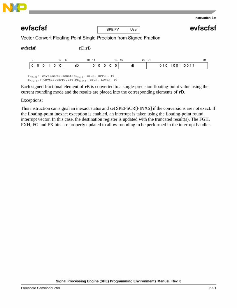
Instruction Set
Signal Processing Engine (SPE) Programming Environments Manual, Rev. 0
Freescale Semiconductor 5-91
evfscfsf evfscfsfVector Convert Floating-Point Single-Precision from Signed Fraction
evfscfsf rD,rB
rD0:31 ← CnvtI32ToFP32Sat(rB0:31, SIGN, UPPER, F)rD32:63 ← CnvtI32ToFP32Sat(rB32:63, SIGN, LOWER, F)
Each signed fractional element of rB is converted to a single-precision floating-point value using the current rounding mode and the results are placed into the corresponding elements of rD.
Exceptions:
This instruction can signal an inexact status and set SPEFSCR[FINXS] if the conversions are not exact. If the floating-point inexact exception is enabled, an interrupt is taken using the floating-point round interrupt vector. In this case, the destination register is updated with the truncated result(s). The FGH, FXH, FG and FX bits are properly updated to allow rounding to be performed in the interrupt handler.
0 5 6 10 11 15 16 20 21 31
0 0 0 1 0 0 rD 0 0 0 0 0 rB 0 1 0 1 0 0 1 0 0 1 1
SPE FV User
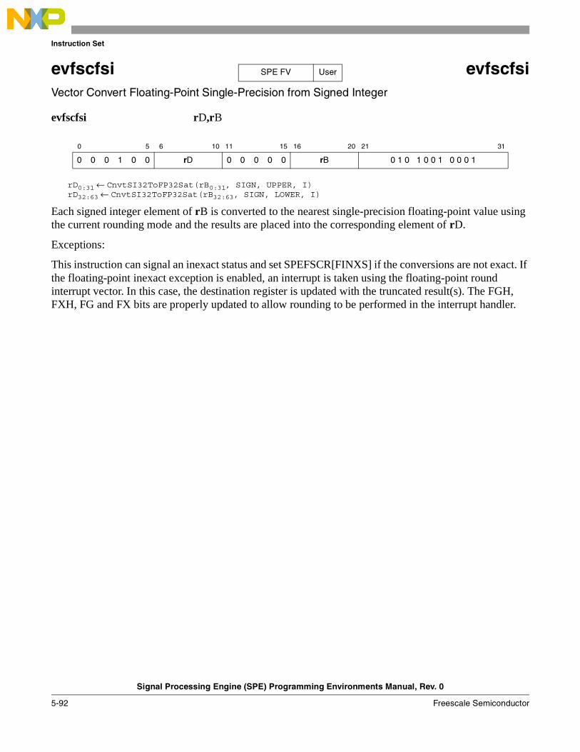
Instruction Set
Signal Processing Engine (SPE) Programming Environments Manual, Rev. 0
5-92 Freescale Semiconductor
evfscfsi evfscfsi Vector Convert Floating-Point Single-Precision from Signed Integer
evfscfsi rD,rB
rD0:31 ← CnvtSI32ToFP32Sat(rB0:31, SIGN, UPPER, I)rD32:63 ← CnvtSI32ToFP32Sat(rB32:63, SIGN, LOWER, I)
Each signed integer element of rB is converted to the nearest single-precision floating-point value using the current rounding mode and the results are placed into the corresponding element of rD.
Exceptions:
This instruction can signal an inexact status and set SPEFSCR[FINXS] if the conversions are not exact. If the floating-point inexact exception is enabled, an interrupt is taken using the floating-point round interrupt vector. In this case, the destination register is updated with the truncated result(s). The FGH, FXH, FG and FX bits are properly updated to allow rounding to be performed in the interrupt handler.
0 5 6 10 11 15 16 20 21 31
0 0 0 1 0 0 rD 0 0 0 0 0 rB 0 1 0 1 0 0 1 0 0 0 1
SPE FV User

Instruction Set
Signal Processing Engine (SPE) Programming Environments Manual, Rev. 0
Freescale Semiconductor 5-93
evfscfuf evfscfufVector Convert Floating-Point Single-Precision from Unsigned Fraction
evfscfuf rD,rB
rD0:31 ← CnvtI32ToFP32Sat(rB0:31, UNSIGN, UPPER, F)rD32:63 ← CnvtI32ToFP32Sat(rB32:63, UNSIGN, LOWER, F)
Each unsigned fractional element of rB is converted to a single-precision floating-point value using the current rounding mode and the results are placed into the corresponding elements of rD.
Exceptions:
This instruction can signal an inexact status and set SPEFSCR[FINXS] if the conversions are not exact. If the floating-point inexact exception is enabled, an interrupt is taken using the floating-point round interrupt vector. In this case, the destination register is updated with the truncated result(s). The FGH, FXH, FG and FX bits are properly updated to allow rounding to be performed in the interrupt handler.
0 5 6 10 11 15 16 20 21 31
0 0 0 1 0 0 rD 0 0 0 0 0 rB 0 1 0 1 0 0 1 0 0 1 0
SPE FV User

Instruction Set
Signal Processing Engine (SPE) Programming Environments Manual, Rev. 0
5-94 Freescale Semiconductor
evfscfui evfscfui Vector Convert Floating-Point Single-Precision from Unsigned Integer
evfscfui rD,rB
rD0:31 ← CnvtI32ToFP32Sat(rB031, UNSIGN, UPPER, I)rD32:63 ← CnvtI32ToFP32Sat(rB32:63, UNSIGN, LOWER, I)
Each unsigned integer element of rB is converted to the nearest single-precision floating-point value using the current rounding mode and the results are placed into the corresponding elements of rD.
Exceptions:
This instruction can signal an inexact status and set SPEFSCR[FINXS] if the conversions are not exact. If the floating-point inexact exception is enabled, an interrupt is taken using the floating-point round interrupt vector. In this case, the destination register is updated with the truncated result(s). The FGH, FXH, FG and FX bits are properly updated to allow rounding to be performed in the interrupt handler.
0 5 6 10 11 15 16 20 21 31
0 0 0 1 0 0 rD 0 0 0 0 0 rB 0 1 0 1 0 0 1 0 0 0 0
SPE FV User
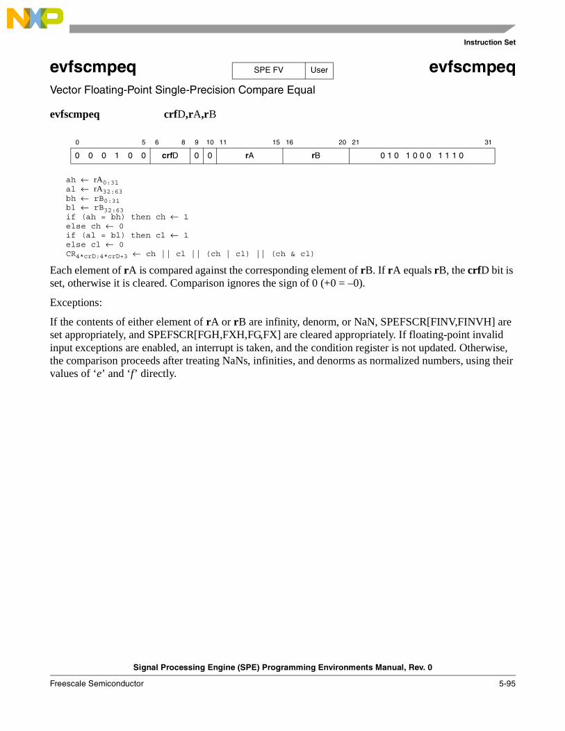
Instruction Set
Signal Processing Engine (SPE) Programming Environments Manual, Rev. 0
Freescale Semiconductor 5-95
evfscmpeq evfscmpeqVector Floating-Point Single-Precision Compare Equal
evfscmpeq crfD,rA,rB
ah ← rA0:31al ← rA32:63bh ← rB0:31bl ← rB32:63if (ah = bh) then ch ← 1else ch ← 0if (al = bl) then cl ← 1else cl ← 0CR4*crD:4*crD+3 ← ch || cl || (ch | cl) || (ch & cl)
Each element of rA is compared against the corresponding element of rB. If rA equals rB, the crfD bit is set, otherwise it is cleared. Comparison ignores the sign of 0 (+0 = –0).
Exceptions:
If the contents of either element of rA or rB are infinity, denorm, or NaN, SPEFSCR[FINV,FINVH] are set appropriately, and SPEFSCR[FGH,FXH,FG,FX] are cleared appropriately. If floating-point invalid input exceptions are enabled, an interrupt is taken, and the condition register is not updated. Otherwise, the comparison proceeds after treating NaNs, infinities, and denorms as normalized numbers, using their values of ‘e’ and ‘f’ directly.
0 5 6 8 9 10 11 15 16 20 21 31
0 0 0 1 0 0 crfD 0 0 rA rB 0 1 0 1 0 0 0 1 1 1 0
SPE FV User
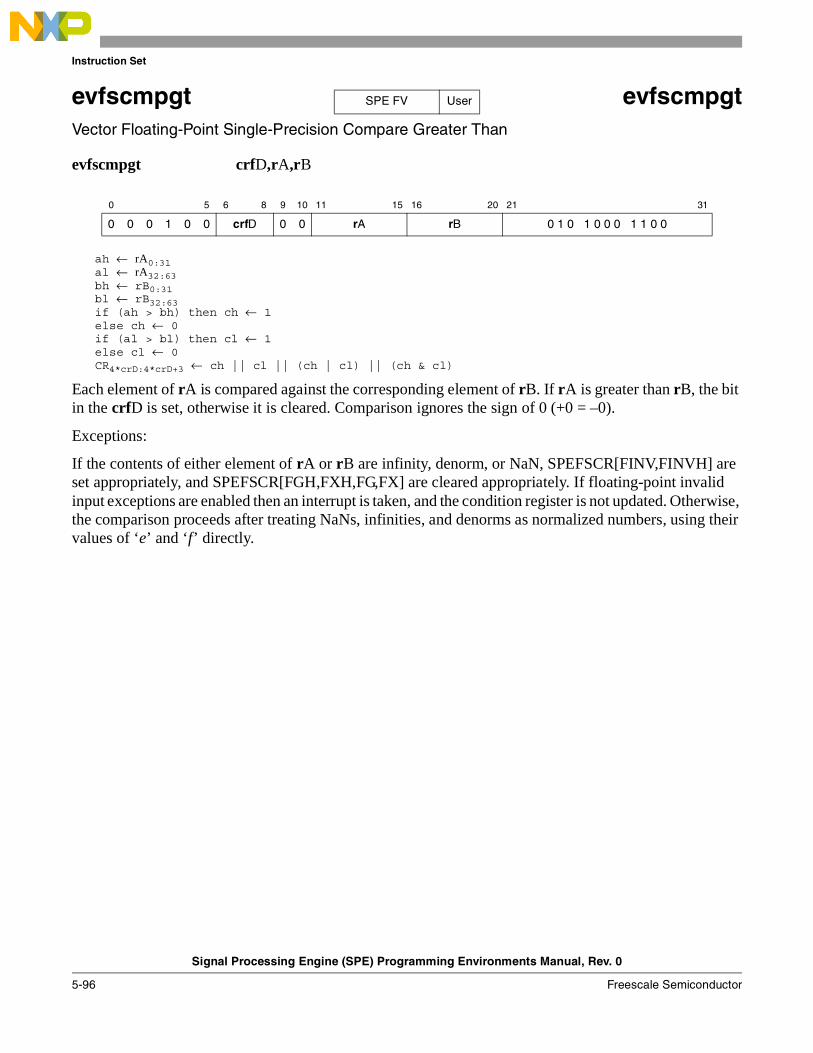
Instruction Set
Signal Processing Engine (SPE) Programming Environments Manual, Rev. 0
5-96 Freescale Semiconductor
evfscmpgt evfscmpgtVector Floating-Point Single-Precision Compare Greater Than
evfscmpgt crfD,rA,rB
ah ← rA0:31al ← rA32:63bh ← rB0:31bl ← rB32:63if (ah > bh) then ch ← 1else ch ← 0if (al > bl) then cl ← 1else cl ← 0CR4*crD:4*crD+3 ← ch || cl || (ch | cl) || (ch & cl)
Each element of rA is compared against the corresponding element of rB. If rA is greater than rB, the bit in the crfD is set, otherwise it is cleared. Comparison ignores the sign of 0 (+0 = –0).
Exceptions:
If the contents of either element of rA or rB are infinity, denorm, or NaN, SPEFSCR[FINV,FINVH] are set appropriately, and SPEFSCR[FGH,FXH,FG,FX] are cleared appropriately. If floating-point invalid input exceptions are enabled then an interrupt is taken, and the condition register is not updated. Otherwise, the comparison proceeds after treating NaNs, infinities, and denorms as normalized numbers, using their values of ‘e’ and ‘f’ directly.
0 5 6 8 9 10 11 15 16 20 21 31
0 0 0 1 0 0 crfD 0 0 rA rB 0 1 0 1 0 0 0 1 1 0 0
SPE FV User

Instruction Set
Signal Processing Engine (SPE) Programming Environments Manual, Rev. 0
Freescale Semiconductor 5-97
evfscmplt evfscmpltVector Floating-Point Single-Precision Compare Less Than
evfscmplt crfD,rA,rB
ah ← rA0:31al ← rA32:63bh ← rB0:31bl ← rB32:63if (ah < bh) then ch ← 1else ch ← 0if (al < bl) then cl ← 1else cl ← 0CR4*crD:4*crD+3 ← ch || cl || (ch | cl) || (ch & cl)
Each element of rA is compared against the corresponding element of rB. If rA is less than rB, the bit in the crfD is set, otherwise it is cleared. Comparison ignores the sign of 0 (+0 = –0).
Exceptions:
If the contents of either element of rA or rB are infinity, denorm, or NaN, SPEFSCR[FINV,FINVH] are set appropriately, and SPEFSCR[FGH,FXH,FG,FX] are cleared appropriately. If floating-point invalid input exceptions are enabled then an interrupt is taken, and the condition register is not updated. Otherwise, the comparison proceeds after treating NaNs, infinities, and denorms as normalized numbers, using their values of ‘e’ and ‘f’ directly.
0 5 6 8 9 10 11 15 16 20 21 31
0 0 0 1 0 0 crfD 0 0 rA rB 0 1 0 1 0 0 0 1 1 0 1
SPE FV User

Instruction Set
Signal Processing Engine (SPE) Programming Environments Manual, Rev. 0
5-98 Freescale Semiconductor
evfsctsf evfsctsfVector Convert Floating-Point Single-Precision to Signed Fraction
evfsctsf rD,rB
rD0:31 ← CnvtFP32ToISat(rB0:31, SIGN, UPPER, ROUND, F)rD32:63 ← CnvtFP32ToISat(rB32:63, SIGN, LOWER, ROUND, F)
Each single-precision floating-point element in rB is converted to a signed fraction using the current rounding mode and the result is saturated if it cannot be represented in a 32-bit signed fraction. NaNs are converted as though they were zero.
Exceptions:
If either element of rB is infinity, denorm, or NaN, or if an overflow occurs, SPEFSCR[FINV,FINVH] are set appropriately and SPEFSCR[FGH,FXH,FG,FX] are cleared appropriately. If SPEFSCR[FINVE] is set, an interrupt is taken, the destination register is not updated, and no other status bits are set.
If either result element of this instruction is inexact and no other interrupt is taken, SPEFSCR[FINXS] is set. If the floating-point inexact exception is enabled, an interrupt is taken using the floating-point round interrupt vector. In this case, the destination register is updated with the truncated result. The FGH, FXH, FG and FX bits are properly updated to allow rounding to be performed in the interrupt handler.
0 5 6 10 11 15 16 20 21 31
0 0 0 1 0 0 rD 0 0 0 0 0 rB 0 1 0 1 0 0 1 0 1 1 1
SPE FV User

Instruction Set
Signal Processing Engine (SPE) Programming Environments Manual, Rev. 0
Freescale Semiconductor 5-99
evfsctsi evfsctsi Vector Convert Floating-Point Single-Precision to Signed Integer
evfsctsi rD,rB
rD0:31 ← CnvtFP32ToISat(rB0:31, SIGN, UPPER, ROUND, I)rD32:63 ← CnvtFP32ToISat(rB32:63, SIGN, LOWER, ROUND, I)
Each single-precision floating-point element in rB is converted to a signed integer using the current rounding mode and the result is saturated if it cannot be represented in a 32-bit integer. NaNs are converted as though they were zero.
Exceptions:
If the contents of either element of rB are infinity, denorm, or NaN, or if an overflow occurs on conversion, SPEFSCR[FINV,FINVH] are set appropriately, and SPEFSCR[FGH,FXH,FG,FX] are cleared appropriately. If SPEFSCR[FINVE] is set, an interrupt is taken, the destination register is not updated, and no other status bits are set.
If either result element of this instruction is inexact and no other interrupt is taken, SPEFSCR[FINXS] is set. If the floating-point inexact exception is enabled, an interrupt is taken using the floating-point round interrupt vector. In this case, the destination register is updated with the truncated result. The FGH, FXH, FG and FX bits are properly updated to allow rounding to be performed in the interrupt handler.
0 5 6 10 11 15 16 20 21 31
0 0 0 1 0 0 rD 0 0 0 0 0 rB 0 1 0 1 0 0 1 0 1 0 1
SPE FV User

Instruction Set
Signal Processing Engine (SPE) Programming Environments Manual, Rev. 0
5-100 Freescale Semiconductor
evfsctsiz evfsctsiz Vector Convert Floating-Point Single-Precision to Signed Integer with Round toward Zero
evfsctsiz rD,rB
rD0:31 ← CnvtFP32ToISat(rB0:31, SIGN, UPPER, TRUNC, I)rD32:63 ← CnvtFP32ToISat(rB32:63, SIGN, LOWER, TRUNC, I)
Each single-precision floating-point element in rB is converted to a signed integer using the rounding mode Round toward Zero and the result is saturated if it cannot be represented in a 32-bit integer. NaNs are converted as though they were zero.
Exceptions:
If either element of rB is infinity, denorm, or NaN, or if an overflow occurs, SPEFSCR[FINV,FINVH] are set appropriately, and SPEFSCR[FGH,FXH,FG,FX] are cleared appropriately. If SPEFSCR[FINVE] is set, an interrupt is taken, the destination register is not updated, and no other status bits are set.
If either result element of this instruction is inexact and no other interrupt is taken, SPEFSCR[FINXS] is set. If the floating-point inexact exception is enabled, an interrupt is taken using the floating-point round interrupt vector. In this case, the destination register is updated with the truncated result. The FGH, FXH, FG and FX bits are properly updated to allow rounding to be performed in the interrupt handler.
0 5 6 10 11 15 16 20 21 31
0 0 0 1 0 0 rD 0 0 0 0 0 rB 0 1 0 1 0 0 1 1 0 1 0
SPE FV User

Instruction Set
Signal Processing Engine (SPE) Programming Environments Manual, Rev. 0
Freescale Semiconductor 5-101
evfsctuf evfsctufVector Convert Floating-Point Single-Precision to Unsigned Fraction
evfsctuf rD,rB
rD0:31 ← CnvtFP32ToISat(rB0:31, UNSIGN, UPPER, ROUND, F)rD32:63 ← CnvtFP32ToISat(rB32:63, UNSIGN, LOWER, ROUND, F)
Each single-precision floating-point element in rB is converted to an unsigned fraction using the current rounding mode and the result is saturated if it cannot be represented in a 32-bit fraction. NaNs are converted as though they were zero.
Exceptions:
If either element of rB is infinity, denorm, or NaN, or if an overflow occurs, SPEFSCR[FINV,FINVH] are set appropriately, and SPEFSCR[FGH,FXH,FG,FX] are cleared appropriately. If SPEFSCR[FINVE] is set, an interrupt is taken, the destination register is not updated, and no other status bits are set.
If either result element of this instruction is inexact and no other interrupt is taken, SPEFSCR[FINXS] is set. If the floating-point inexact exception is enabled, an interrupt is taken using the floating-point round interrupt vector. In this case, the destination register is updated with the truncated result. The FGH, FXH, FG and FX bits are properly updated to allow rounding to be performed in the interrupt handler.
0 5 6 10 11 15 16 20 21 31
0 0 0 1 0 0 rD 0 0 0 0 0 rB 0 1 0 1 0 0 1 0 1 1 0
SPE FV User
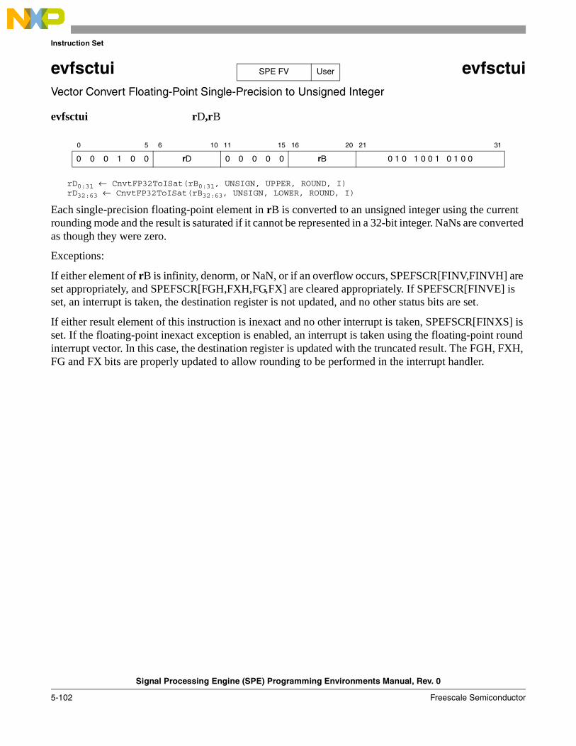
Instruction Set
Signal Processing Engine (SPE) Programming Environments Manual, Rev. 0
5-102 Freescale Semiconductor
evfsctui evfsctui Vector Convert Floating-Point Single-Precision to Unsigned Integer
evfsctui rD,rB
rD0:31 ← CnvtFP32ToISat(rB0:31, UNSIGN, UPPER, ROUND, I)rD32:63 ← CnvtFP32ToISat(rB32:63, UNSIGN, LOWER, ROUND, I)
Each single-precision floating-point element in rB is converted to an unsigned integer using the current rounding mode and the result is saturated if it cannot be represented in a 32-bit integer. NaNs are converted as though they were zero.
Exceptions:
If either element of rB is infinity, denorm, or NaN, or if an overflow occurs, SPEFSCR[FINV,FINVH] are set appropriately, and SPEFSCR[FGH,FXH,FG,FX] are cleared appropriately. If SPEFSCR[FINVE] is set, an interrupt is taken, the destination register is not updated, and no other status bits are set.
If either result element of this instruction is inexact and no other interrupt is taken, SPEFSCR[FINXS] is set. If the floating-point inexact exception is enabled, an interrupt is taken using the floating-point round interrupt vector. In this case, the destination register is updated with the truncated result. The FGH, FXH, FG and FX bits are properly updated to allow rounding to be performed in the interrupt handler.
0 5 6 10 11 15 16 20 21 31
0 0 0 1 0 0 rD 0 0 0 0 0 rB 0 1 0 1 0 0 1 0 1 0 0
SPE FV User

Instruction Set
Signal Processing Engine (SPE) Programming Environments Manual, Rev. 0
Freescale Semiconductor 5-103
evfsctuiz evfsctuiz Vector Convert Floating-Point Single-Precision to Unsigned Integer with Round toward Zero
evfsctuiz rD,rB
rD0:31 ← CnvtFP32ToISat(rB0:31, UNSIGN, UPPER, TRUNC, I)rD32:63 ← CnvtFP32ToISat(rB32:63, UNSIGN, LOWER, TRUNC, I)
Each single-precision floating-point element in rB is converted to an unsigned integer using the rounding mode Round toward Zero and the result is saturated if it cannot be represented in a 32-bit integer. NaNs are converted as though they were zero.
Exceptions:
If either element of rB is infinity, denorm, or NaN, or if an overflow occurs, SPEFSCR[FINV,FINVH] are set appropriately, and SPEFSCR[FGH,FXH,FG,FX] are cleared appropriately. If SPEFSCR[FINVE] is set, an interrupt is taken, the destination register is not updated, and no other status bits are set.
If either result element of this instruction is inexact and no other interrupt is taken, SPEFSCR[FINXS] is set. If the floating-point inexact exception is enabled, an interrupt is taken using the floating-point round interrupt vector. In this case, the destination register is updated with the truncated result. The FGH, FXH, FG and FX bits are properly updated to allow rounding to be performed in the interrupt handler.
0 5 6 10 11 15 16 20 21 31
0 0 0 1 0 0 rD 0 0 0 0 0 rB 0 1 0 1 0 0 1 1 0 0 0
SPE FV User
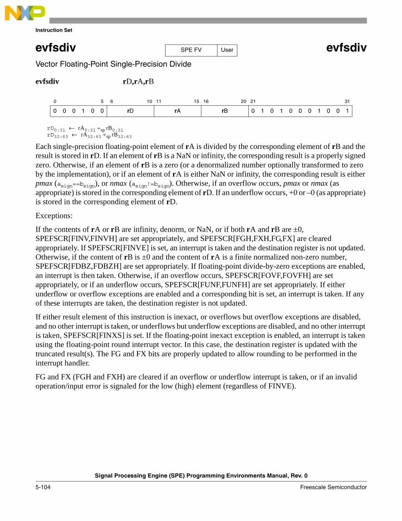
Instruction Set
Signal Processing Engine (SPE) Programming Environments Manual, Rev. 0
5-104 Freescale Semiconductor
evfsdiv evfsdivVector Floating-Point Single-Precision Divide
evfsdiv rD,rA,rB
rD0:31 ← rA0:31 ÷sp rB0:31rD32:63 ← rA32:63 ÷sp rB32:63
Each single-precision floating-point element of rA is divided by the corresponding element of rB and the result is stored in rD. If an element of rB is a NaN or infinity, the corresponding result is a properly signed zero. Otherwise, if an element of rB is a zero (or a denormalized number optionally transformed to zero by the implementation), or if an element of rA is either NaN or infinity, the corresponding result is either pmax (asign==bsign), or nmax (asign!=bsign). Otherwise, if an overflow occurs, pmax or nmax (as appropriate) is stored in the corresponding element of rD. If an underflow occurs, +0 or –0 (as appropriate) is stored in the corresponding element of rD.
Exceptions:
If the contents of rA or rB are infinity, denorm, or NaN, or if both rA and rB are ±0, SPEFSCR[FINV,FINVH] are set appropriately, and SPEFSCR[FGH,FXH,FG,FX] are cleared appropriately. If SPEFSCR[FINVE] is set, an interrupt is taken and the destination register is not updated. Otherwise, if the content of rB is ±0 and the content of rA is a finite normalized non-zero number, SPEFSCR[FDBZ,FDBZH] are set appropriately. If floating-point divide-by-zero exceptions are enabled, an interrupt is then taken. Otherwise, if an overflow occurs, SPEFSCR[FOVF,FOVFH] are set appropriately, or if an underflow occurs, SPEFSCR[FUNF,FUNFH] are set appropriately. If either underflow or overflow exceptions are enabled and a corresponding bit is set, an interrupt is taken. If any of these interrupts are taken, the destination register is not updated.
If either result element of this instruction is inexact, or overflows but overflow exceptions are disabled, and no other interrupt is taken, or underflows but underflow exceptions are disabled, and no other interrupt is taken, SPEFSCR[FINXS] is set. If the floating-point inexact exception is enabled, an interrupt is taken using the floating-point round interrupt vector. In this case, the destination register is updated with the truncated result(s). The FG and FX bits are properly updated to allow rounding to be performed in the interrupt handler.
FG and FX (FGH and FXH) are cleared if an overflow or underflow interrupt is taken, or if an invalid operation/input error is signaled for the low (high) element (regardless of FINVE).
0 5 6 10 11 15 16 20 21 31
0 0 0 1 0 0 rD rA rB 0 1 0 1 0 0 0 1 0 0 1
SPE FV User
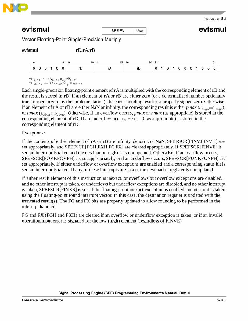
Instruction Set
Signal Processing Engine (SPE) Programming Environments Manual, Rev. 0
Freescale Semiconductor 5-105
evfsmul evfsmulVector Floating-Point Single-Precision Multiply
evfsmul rD,rA,rB
rD0:31 ← rA0:31 ×sp rB0:31rD32:63 ← rA32:63 ×sp rB32:63
Each single-precision floating-point element of rA is multiplied with the corresponding element of rB and the result is stored in rD. If an element of rA or rB are either zero (or a denormalized number optionally transformed to zero by the implementation), the corresponding result is a properly signed zero. Otherwise, if an element of rA or rB are either NaN or infinity, the corresponding result is either pmax (asign==bsign), or nmax (asign!=bsign). Otherwise, if an overflow occurs, pmax or nmax (as appropriate) is stored in the corresponding element of rD. If an underflow occurs, +0 or –0 (as appropriate) is stored in the corresponding element of rD.
Exceptions:
If the contents of either element of rA or rB are infinity, denorm, or NaN, SPEFSCR[FINV,FINVH] are set appropriately, and SPEFSCR[FGH,FXH,FG,FX] are cleared appropriately. If SPEFSCR[FINVE] is set, an interrupt is taken and the destination register is not updated. Otherwise, if an overflow occurs, SPEFSCR[FOVF,FOVFH] are set appropriately, or if an underflow occurs, SPEFSCR[FUNF,FUNFH] are set appropriately. If either underflow or overflow exceptions are enabled and a corresponding status bit is set, an interrupt is taken. If any of these interrupts are taken, the destination register is not updated.
If either result element of this instruction is inexact, or overflows but overflow exceptions are disabled, and no other interrupt is taken, or underflows but underflow exceptions are disabled, and no other interrupt is taken, SPEFSCR[FINXS] is set. If the floating-point inexact exception is enabled, an interrupt is taken using the floating-point round interrupt vector. In this case, the destination register is updated with the truncated result(s). The FG and FX bits are properly updated to allow rounding to be performed in the interrupt handler.
FG and FX (FGH and FXH) are cleared if an overflow or underflow exception is taken, or if an invalid operation/input error is signaled for the low (high) element (regardless of FINVE).
0 5 6 10 11 15 16 20 21 31
0 0 0 1 0 0 rD rA rB 0 1 0 1 0 0 0 1 0 0 0
SPE FV User
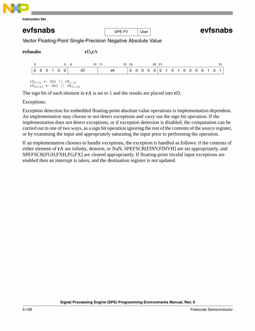
Instruction Set
Signal Processing Engine (SPE) Programming Environments Manual, Rev. 0
5-106 Freescale Semiconductor
evfsnabs evfsnabsVector Floating-Point Single-Precision Negative Absolute Value
evfsnabs rD,rA
rD0:31 ← 0b1 || rA1:31rD32:63 ← 0b1 || rA33:63
The sign bit of each element in rA is set to 1 and the results are placed into rD.
Exceptions:
Exception detection for embedded floating-point absolute value operations is implementation dependent. An implementation may choose to not detect exceptions and carry out the sign bit operation. If the implementation does not detect exceptions, or if exception detection is disabled, the computation can be carried out in one of two ways, as a sign bit operation ignoring the rest of the contents of the source register, or by examining the input and appropriately saturating the input prior to performing the operation.
If an implementation chooses to handle exceptions, the exception is handled as follows: if the contents of either element of rA are infinity, denorm, or NaN, SPEFSCR[FINV,FINVH] are set appropriately, and SPEFSCR[FGH,FXH,FG,FX] are cleared appropriately. If floating-point invalid input exceptions are enabled then an interrupt is taken, and the destination register is not updated.
0 5 6 10 11 15 16 20 21 31
0 0 0 1 0 0 rD rA 0 0 0 0 0 0 1 0 1 0 0 0 0 1 0 1
SPE FV User
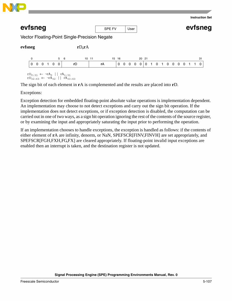
Instruction Set
Signal Processing Engine (SPE) Programming Environments Manual, Rev. 0
Freescale Semiconductor 5-107
evfsneg evfsnegVector Floating-Point Single-Precision Negate
evfsneg rD,rA
rD0:31 ← ¬rA0 || rA1:31rD32:63 ← ¬rA32 || rA33:63
The sign bit of each element in rA is complemented and the results are placed into rD.
Exceptions:
Exception detection for embedded floating-point absolute value operations is implementation dependent. An implementation may choose to not detect exceptions and carry out the sign bit operation. If the implementation does not detect exceptions, or if exception detection is disabled, the computation can be carried out in one of two ways, as a sign bit operation ignoring the rest of the contents of the source register, or by examining the input and appropriately saturating the input prior to performing the operation.
If an implementation chooses to handle exceptions, the exception is handled as follows: if the contents of either element of rA are infinity, denorm, or NaN, SPEFSCR[FINV,FINVH] are set appropriately, and SPEFSCR[FGH,FXH,FG,FX] are cleared appropriately. If floating-point invalid input exceptions are enabled then an interrupt is taken, and the destination register is not updated.
0 5 6 10 11 15 16 20 21 31
0 0 0 1 0 0 rD rA 0 0 0 0 0 0 1 0 1 0 0 0 0 1 1 0
SPE FV User
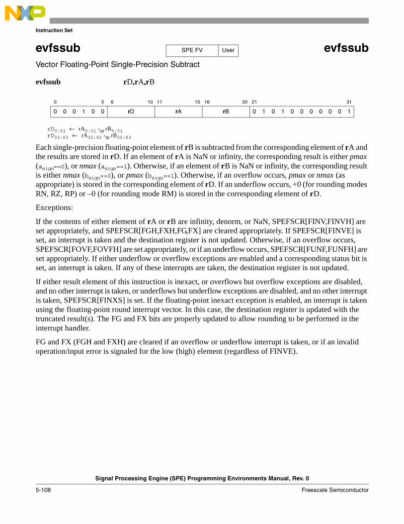
Instruction Set
Signal Processing Engine (SPE) Programming Environments Manual, Rev. 0
5-108 Freescale Semiconductor
evfssub evfssubVector Floating-Point Single-Precision Subtract
evfssub rD,rA,rB
rD0:31 ← rA0:31 -sp rB0:31rD32:63 ← rA32:63 -sp rB32:63
Each single-precision floating-point element of rB is subtracted from the corresponding element of rA and the results are stored in rD. If an element of rA is NaN or infinity, the corresponding result is either pmax (asign==0), or nmax (asign==1). Otherwise, if an element of rB is NaN or infinity, the corresponding result is either nmax (bsign==0), or pmax (bsign==1). Otherwise, if an overflow occurs, pmax or nmax (as appropriate) is stored in the corresponding element of rD. If an underflow occurs, +0 (for rounding modes RN, RZ, RP) or –0 (for rounding mode RM) is stored in the corresponding element of rD.
Exceptions:
If the contents of either element of rA or rB are infinity, denorm, or NaN, SPEFSCR[FINV,FINVH] are set appropriately, and SPEFSCR[FGH,FXH,FG,FX] are cleared appropriately. If SPEFSCR[FINVE] is set, an interrupt is taken and the destination register is not updated. Otherwise, if an overflow occurs, SPEFSCR[FOVF,FOVFH] are set appropriately, or if an underflow occurs, SPEFSCR[FUNF,FUNFH] are set appropriately. If either underflow or overflow exceptions are enabled and a corresponding status bit is set, an interrupt is taken. If any of these interrupts are taken, the destination register is not updated.
If either result element of this instruction is inexact, or overflows but overflow exceptions are disabled, and no other interrupt is taken, or underflows but underflow exceptions are disabled, and no other interrupt is taken, SPEFSCR[FINXS] is set. If the floating-point inexact exception is enabled, an interrupt is taken using the floating-point round interrupt vector. In this case, the destination register is updated with the truncated result(s). The FG and FX bits are properly updated to allow rounding to be performed in the interrupt handler.
FG and FX (FGH and FXH) are cleared if an overflow or underflow interrupt is taken, or if an invalid operation/input error is signaled for the low (high) element (regardless of FINVE).
0 5 6 10 11 15 16 20 21 31
0 0 0 1 0 0 rD rA rB 0 1 0 1 0 0 0 0 0 0 1
SPE FV User
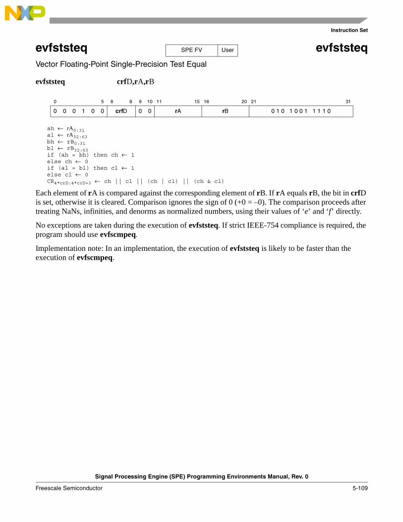
Instruction Set
Signal Processing Engine (SPE) Programming Environments Manual, Rev. 0
Freescale Semiconductor 5-109
evfststeq evfststeqVector Floating-Point Single-Precision Test Equal
evfststeq crfD,rA,rB
ah ← rA0:31al ← rA32:63bh ← rB0:31bl ← rB32:63if (ah = bh) then ch ← 1else ch ← 0if (al = bl) then cl ← 1else cl ← 0CR4*crD:4*crD+3 ← ch || cl || (ch | cl) || (ch & cl)
Each element of rA is compared against the corresponding element of rB. If rA equals rB, the bit in crfD is set, otherwise it is cleared. Comparison ignores the sign of 0 (+0 = –0). The comparison proceeds after treating NaNs, infinities, and denorms as normalized numbers, using their values of ‘e’ and ‘f’ directly.
No exceptions are taken during the execution of evfststeq. If strict IEEE-754 compliance is required, the program should use evfscmpeq.
Implementation note: In an implementation, the execution of evfststeq is likely to be faster than the execution of evfscmpeq.
0 5 6 8 9 10 11 15 16 20 21 31
0 0 0 1 0 0 crfD 0 0 rA rB 0 1 0 1 0 0 1 1 1 1 0
SPE FV User
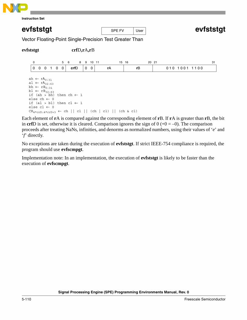
Instruction Set
Signal Processing Engine (SPE) Programming Environments Manual, Rev. 0
5-110 Freescale Semiconductor
evfststgt evfststgtVector Floating-Point Single-Precision Test Greater Than
evfststgt crfD,rA,rB
ah ← rA0:31al ← rA32:63bh ← rB0:31bl ← rB32:63if (ah > bh) then ch ← 1else ch ← 0if (al > bl) then cl ← 1else cl ← 0CR4*crD:4*crD+3 ← ch || cl || (ch | cl) || (ch & cl)
Each element of rA is compared against the corresponding element of rB. If rA is greater than rB, the bit in crfD is set, otherwise it is cleared. Comparison ignores the sign of 0 (+0 = –0). The comparison proceeds after treating NaNs, infinities, and denorms as normalized numbers, using their values of ‘e’ and ‘f’ directly.
No exceptions are taken during the execution of evfststgt. If strict IEEE-754 compliance is required, the program should use evfscmpgt.
Implementation note: In an implementation, the execution of evfststgt is likely to be faster than the execution of evfscmpgt.
0 5 6 8 9 10 11 15 16 20 21 31
0 0 0 1 0 0 crfD 0 0 rA rB 0 1 0 1 0 0 1 1 1 0 0
SPE FV User
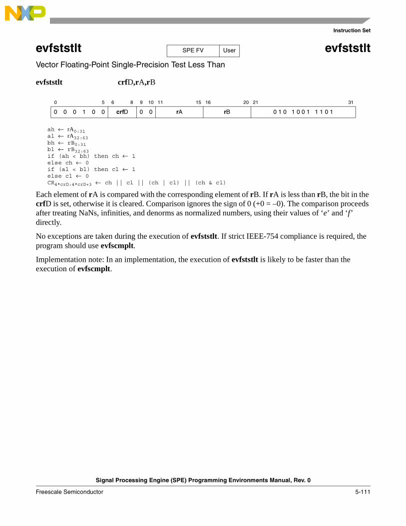
Instruction Set
Signal Processing Engine (SPE) Programming Environments Manual, Rev. 0
Freescale Semiconductor 5-111
evfststlt evfststltVector Floating-Point Single-Precision Test Less Than
evfststlt crfD,rA,rB
ah ← rA0:31al ← rA32:63bh ← rB0:31bl ← rB32:63if (ah < bh) then ch ← 1else ch ← 0if (al < bl) then cl ← 1else cl ← 0CR4*crD:4*crD+3 ← ch || cl || (ch | cl) || (ch & cl)
Each element of rA is compared with the corresponding element of rB. If rA is less than rB, the bit in the crfD is set, otherwise it is cleared. Comparison ignores the sign of 0 (+0 = –0). The comparison proceeds after treating NaNs, infinities, and denorms as normalized numbers, using their values of ‘e’ and ‘f’ directly.
No exceptions are taken during the execution of evfststlt. If strict IEEE-754 compliance is required, the program should use evfscmplt.
Implementation note: In an implementation, the execution of evfststlt is likely to be faster than the execution of evfscmplt.
0 5 6 8 9 10 11 15 16 20 21 31
0 0 0 1 0 0 crfD 0 0 rA rB 0 1 0 1 0 0 1 1 1 0 1
SPE FV User
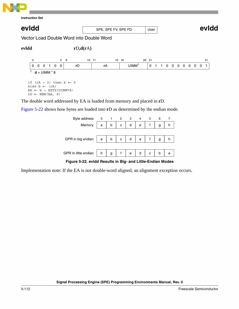
Instruction Set
Signal Processing Engine (SPE) Programming Environments Manual, Rev. 0
5-112 Freescale Semiconductor
evldd evlddVector Load Double Word into Double Word
evldd rD,d(rA)
if (rA = 0) then b ← 0else b ← (rA)EA ← b + EXTZ(UIMM*8)rD ← MEM(EA, 8)
The double word addressed by EA is loaded from memory and placed in rD.
Figure 5-22 shows how bytes are loaded into rD as determined by the endian mode.
Figure 5-22. evldd Results in Big- and Little-Endian Modes
Implementation note: If the EA is not double-word aligned, an alignment exception occurs.
0 5 6 10 11 15 16 20 21 31
0 0 0 1 0 0 rD rA UIMM1
1 d = UIMM * 8
0 1 1 0 0 0 0 0 0 0 1
SPE, SPE FV, SPE FD User
c d e f h
0 1 2 3 4 5 6 7
a b g
c d e f ha b g
f e d c ah g b
Memory
GPR in big endian
GPR in little endian
Byte address

Instruction Set
Signal Processing Engine (SPE) Programming Environments Manual, Rev. 0
Freescale Semiconductor 5-113
evlddx evlddxVector Load Double Word into Double Word Indexed
evlddx rD,rA,rB
if (rA = 0) then b ← 0else b ← (rA)EA ← b + (rB)rD ← MEM(EA, 8)
The double word addressed by EA is loaded from memory and placed in rD.
Figure 5-23 shows how bytes are loaded into rD as determined by the endian mode.
Figure 5-23. evlddx Results in Big- and Little-Endian Modes
Implementation note: If the EA is not double-word aligned, an alignment exception occurs.
0 5 6 10 11 15 16 20 21 31
0 0 0 1 0 0 rD rA rB 0 1 1 0 0 0 0 0 0 0 0
SPE, SPE FV, SPE FD User
c d e f h
0 1 2 3 4 5 6 7
a b g
c d e f ha b g
f e d c ah g b
Memory
GPR in big endian
GPR in little endian
Byte address
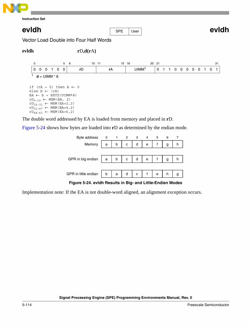
Instruction Set
Signal Processing Engine (SPE) Programming Environments Manual, Rev. 0
5-114 Freescale Semiconductor
evldh evldhVector Load Double into Four Half Words
evldh rD,d(rA)
if (rA = 0) then b ← 0else b ← (rA)EA ← b + EXTZ(UIMM*8)rD0:15 ← MEM(EA, 2)rD16:31 ← MEM(EA+2,2)rD32:47 ← MEM(EA+4,2)rD48:63 ← MEM(EA+6,2)
The double word addressed by EA is loaded from memory and placed in rD.
Figure 5-24 shows how bytes are loaded into rD as determined by the endian mode.
Figure 5-24. evldh Results in Big- and Little-Endian Modes
Implementation note: If the EA is not double-word aligned, an alignment exception occurs.
0 5 6 10 11 15 16 20 21 31
0 0 0 1 0 0 rD rA UIMM1
1 d = UIMM * 8
0 1 1 0 0 0 0 0 1 0 1
SPE User
c d e f h
0 1 2 3 4 5 6 7
a b g
c d e f ha b g
d c f e gb a h
Memory
GPR in big endian
GPR in little endian
Byte address
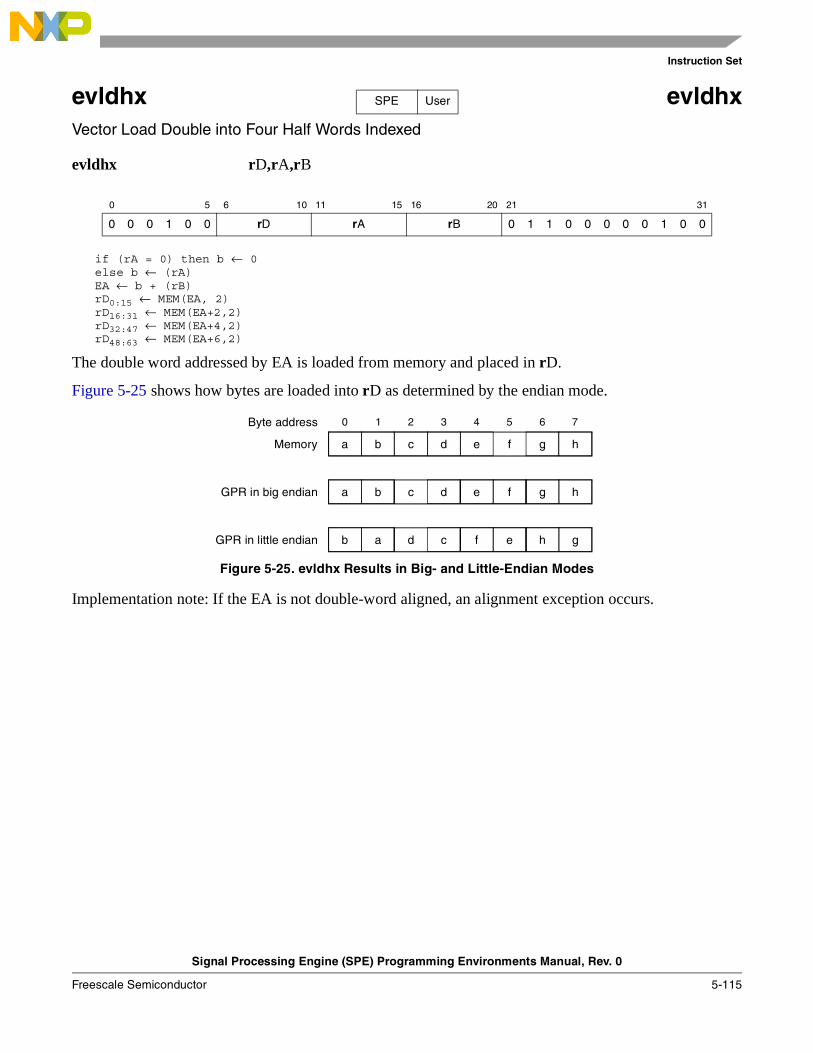
Instruction Set
Signal Processing Engine (SPE) Programming Environments Manual, Rev. 0
Freescale Semiconductor 5-115
evldhx evldhxVector Load Double into Four Half Words Indexed
evldhx rD,rA,rB
if (rA = 0) then b ← 0else b ← (rA)EA ← b + (rB)rD0:15 ← MEM(EA, 2)rD16:31 ← MEM(EA+2,2)rD32:47 ← MEM(EA+4,2)rD48:63 ← MEM(EA+6,2)
The double word addressed by EA is loaded from memory and placed in rD.
Figure 5-25 shows how bytes are loaded into rD as determined by the endian mode.
Figure 5-25. evldhx Results in Big- and Little-Endian Modes
Implementation note: If the EA is not double-word aligned, an alignment exception occurs.
0 5 6 10 11 15 16 20 21 31
0 0 0 1 0 0 rD rA rB 0 1 1 0 0 0 0 0 1 0 0
SPE User
c d e f h
0 1 2 3 4 5 6 7
a b g
c d e f ha b g
d c f e gb a h
Memory
GPR in big endian
GPR in little endian
Byte address
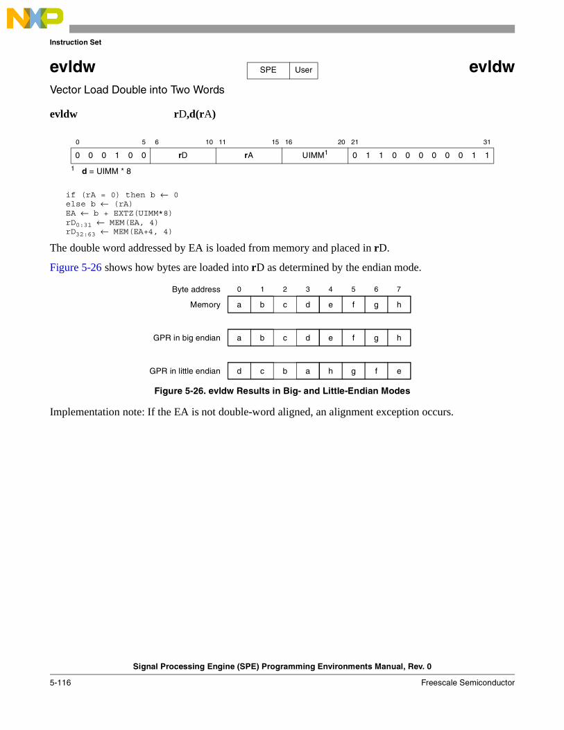
Instruction Set
Signal Processing Engine (SPE) Programming Environments Manual, Rev. 0
5-116 Freescale Semiconductor
evldw evldwVector Load Double into Two Words
evldw rD,d(rA)
if (rA = 0) then b ← 0else b ← (rA)EA ← b + EXTZ(UIMM*8)rD0:31 ← MEM(EA, 4)rD32:63 ← MEM(EA+4, 4)
The double word addressed by EA is loaded from memory and placed in rD.
Figure 5-26 shows how bytes are loaded into rD as determined by the endian mode.
Figure 5-26. evldw Results in Big- and Little-Endian Modes
Implementation note: If the EA is not double-word aligned, an alignment exception occurs.
0 5 6 10 11 15 16 20 21 31
0 0 0 1 0 0 rD rA UIMM1
1 d = UIMM * 8
0 1 1 0 0 0 0 0 0 1 1
SPE User
c d e f h
0 1 2 3 4 5 6 7
a b g
c d e f ha b g
b a h g ed c f
Memory
GPR in big endian
GPR in little endian
Byte address
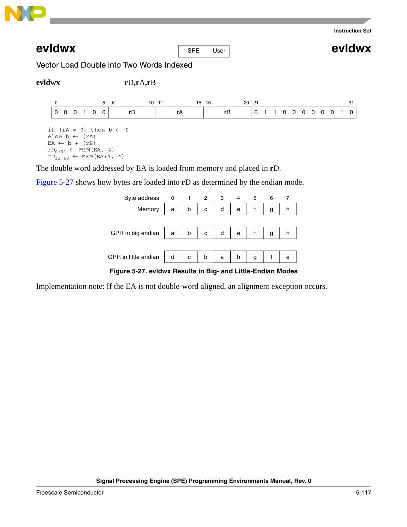
Instruction Set
Signal Processing Engine (SPE) Programming Environments Manual, Rev. 0
Freescale Semiconductor 5-117
evldwx evldwxVector Load Double into Two Words Indexed
evldwx rD,rA,rB
if (rA = 0) then b ← 0else b ← (rA)EA ← b + (rB)rD0:31 ← MEM(EA, 4)rD32:63 ← MEM(EA+4, 4)
The double word addressed by EA is loaded from memory and placed in rD.
Figure 5-27 shows how bytes are loaded into rD as determined by the endian mode.
Figure 5-27. evldwx Results in Big- and Little-Endian Modes
Implementation note: If the EA is not double-word aligned, an alignment exception occurs.
0 5 6 10 11 15 16 20 21 31
0 0 0 1 0 0 rD rA rB 0 1 1 0 0 0 0 0 0 1 0
SPE User
c d e f h
0 1 2 3 4 5 6 7
a b g
c d e f ha b g
b a h g ed c f
Memory
GPR in big endian
GPR in little endian
Byte address
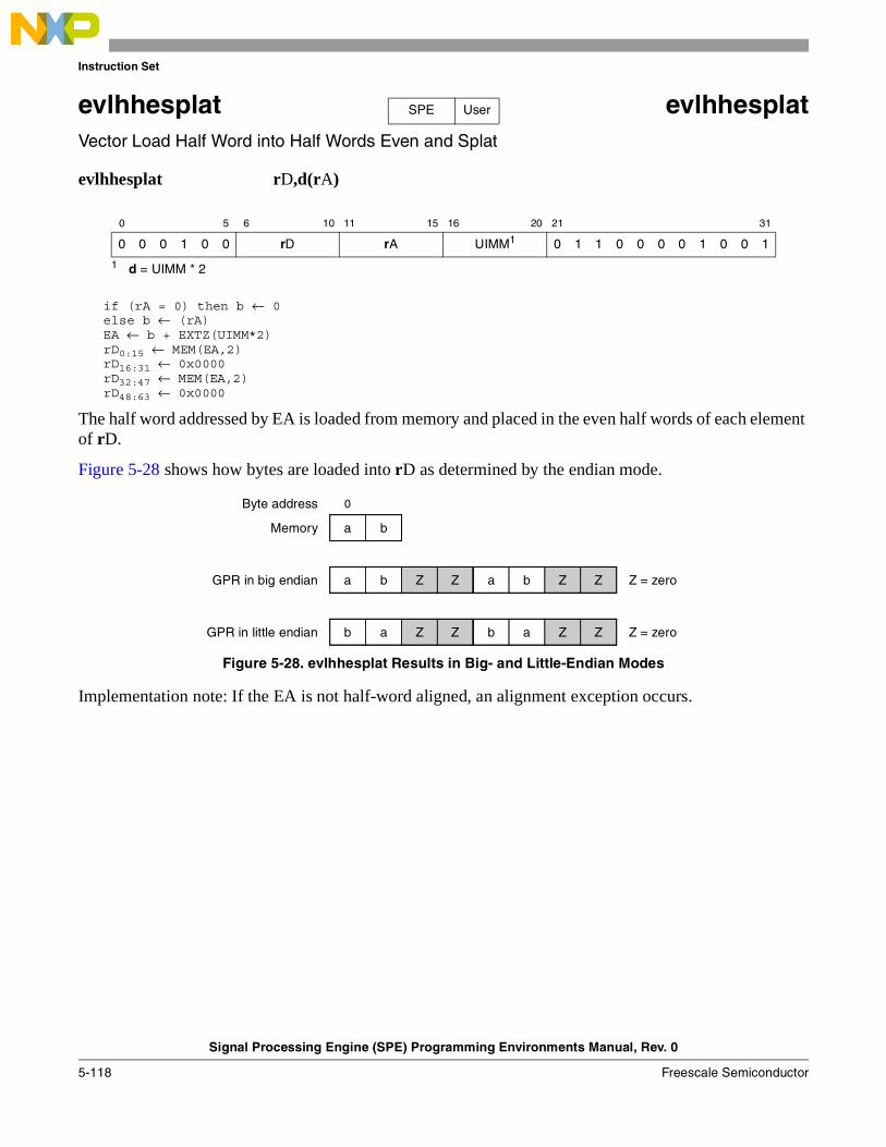
Instruction Set
Signal Processing Engine (SPE) Programming Environments Manual, Rev. 0
5-118 Freescale Semiconductor
evlhhesplat evlhhesplatVector Load Half Word into Half Words Even and Splat
evlhhesplat rD,d(rA)
if (rA = 0) then b ← 0else b ← (rA)EA ← b + EXTZ(UIMM*2)rD0:15 ← MEM(EA,2)rD16:31 ← 0x0000rD32:47 ← MEM(EA,2)rD48:63 ← 0x0000
The half word addressed by EA is loaded from memory and placed in the even half words of each element of rD.
Figure 5-28 shows how bytes are loaded into rD as determined by the endian mode.
Figure 5-28. evlhhesplat Results in Big- and Little-Endian Modes
Implementation note: If the EA is not half-word aligned, an alignment exception occurs.
0 5 6 10 11 15 16 20 21 31
0 0 0 1 0 0 rD rA UIMM1
1 d = UIMM * 2
0 1 1 0 0 0 0 1 0 0 1
SPE User
0
a b
Z Z a b Za b Z
Z Z b a Zb a Z
Memory
GPR in big endian
GPR in little endian
Byte address
Z = zero
Z = zero
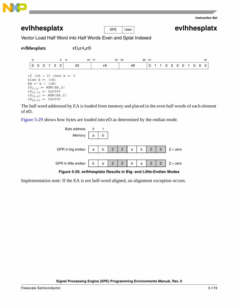
Instruction Set
Signal Processing Engine (SPE) Programming Environments Manual, Rev. 0
Freescale Semiconductor 5-119
evlhhesplatx evlhhesplatxVector Load Half Word into Half Words Even and Splat Indexed
evlhhesplatx rD,rA,rB
if (rA = 0) then b ← 0else b ← (rA)EA ← b + (rB)rD0:15 ← MEM(EA,2)rD16:31 ← 0x0000rD32:47 ← MEM(EA,2)rD48:63 ← 0x0000
The half word addressed by EA is loaded from memory and placed in the even half words of each element of rD.
Figure 5-29 shows how bytes are loaded into rD as determined by the endian mode.
Figure 5-29. evlhhesplatx Results in Big- and Little-Endian Modes
Implementation note: If the EA is not half-word aligned, an alignment exception occurs.
0 5 6 10 11 15 16 20 21 31
0 0 0 1 0 0 rD rA rB 0 1 1 0 0 0 0 1 0 0 0
SPE User
0 1
a b
Z Z a b Za b Z
Z Z b a Zb a Z
Memory
GPR in big endian
GPR in little endian
Byte address
Z = zero
Z = zero
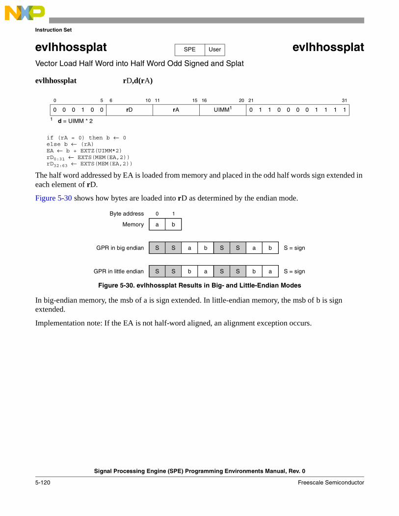
Instruction Set
Signal Processing Engine (SPE) Programming Environments Manual, Rev. 0
5-120 Freescale Semiconductor
evlhhossplat evlhhossplatVector Load Half Word into Half Word Odd Signed and Splat
evlhhossplat rD,d(rA)
if (rA = 0) then b ← 0else b ← (rA)EA ← b + EXTZ(UIMM*2)rD0:31 ← EXTS(MEM(EA,2))rD32:63 ← EXTS(MEM(EA,2))
The half word addressed by EA is loaded from memory and placed in the odd half words sign extended in each element of rD.
Figure 5-30 shows how bytes are loaded into rD as determined by the endian mode.
Figure 5-30. evlhhossplat Results in Big- and Little-Endian Modes
In big-endian memory, the msb of a is sign extended. In little-endian memory, the msb of b is sign extended.
Implementation note: If the EA is not half-word aligned, an alignment exception occurs.
0 5 6 10 11 15 16 20 21 31
0 0 0 1 0 0 rD rA UIMM1
1 d = UIMM * 2
0 1 1 0 0 0 0 1 1 1 1
SPE User
0 1
a b
a b S S bS S a
b a S S aS S b
Memory
GPR in big endian
GPR in little endian
Byte address
S = sign
S = sign
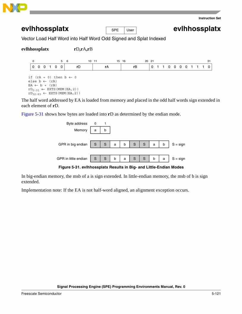
Instruction Set
Signal Processing Engine (SPE) Programming Environments Manual, Rev. 0
Freescale Semiconductor 5-121
evlhhossplatx evlhhossplatxVector Load Half Word into Half Word Odd Signed and Splat Indexed
evlhhossplatx rD,rA,rB
if (rA = 0) then b ← 0else b ← (rA)EA ← b + (rB)rD0:31 ← EXTS(MEM(EA,2))rD32:63 ← EXTS(MEM(EA,2))
The half word addressed by EA is loaded from memory and placed in the odd half words sign extended in each element of rD.
Figure 5-31 shows how bytes are loaded into rD as determined by the endian mode.
Figure 5-31. evlhhossplatx Results in Big- and Little-Endian Modes
In big-endian memory, the msb of a is sign extended. In little-endian memory, the msb of b is sign extended.
Implementation note: If the EA is not half-word aligned, an alignment exception occurs.
0 5 6 10 11 15 16 20 21 31
0 0 0 1 0 0 rD rA rB 0 1 1 0 0 0 0 1 1 1 0
SPE User
0 1
a b
a b S S bS S a
b a S S aS S b
Memory
GPR in big endian
GPR in little endian
Byte address
S = sign
S = sign
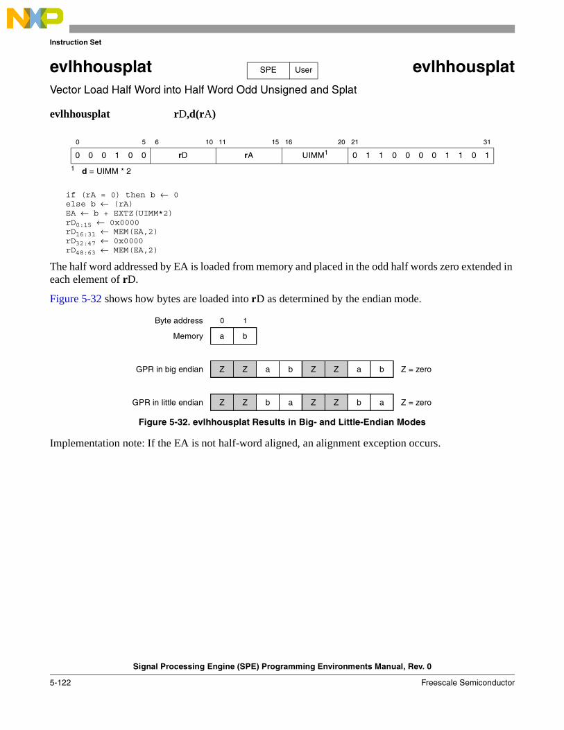
Instruction Set
Signal Processing Engine (SPE) Programming Environments Manual, Rev. 0
5-122 Freescale Semiconductor
evlhhousplat evlhhousplatVector Load Half Word into Half Word Odd Unsigned and Splat
evlhhousplat rD,d(rA)
if (rA = 0) then b ← 0else b ← (rA)EA ← b + EXTZ(UIMM*2)rD0:15 ← 0x0000rD16:31 ← MEM(EA,2)rD32:47 ← 0x0000rD48:63 ← MEM(EA,2)
The half word addressed by EA is loaded from memory and placed in the odd half words zero extended in each element of rD.
Figure 5-32 shows how bytes are loaded into rD as determined by the endian mode.
Figure 5-32. evlhhousplat Results in Big- and Little-Endian Modes
Implementation note: If the EA is not half-word aligned, an alignment exception occurs.
0 5 6 10 11 15 16 20 21 31
0 0 0 1 0 0 rD rA UIMM1
1 d = UIMM * 2
0 1 1 0 0 0 0 1 1 0 1
SPE User
0 1
a b
a b Z Z bZ Z a
b a Z Z aZ Z b
Memory
GPR in big endian
GPR in little endian
Byte address
Z = zero
Z = zero

Instruction Set
Signal Processing Engine (SPE) Programming Environments Manual, Rev. 0
Freescale Semiconductor 5-123
evlhhousplatx evlhhousplatxVector Load Half Word into Half Word Odd Unsigned and Splat Indexed
evlhhousplatx rD,rA,rB
if (rA = 0) then b ← 0else b ← (rA)EA ← b + (rB)rD0:15 ← 0x0000rD16:31 ← MEM(EA,2)rD32:47 ← 0x0000rD48:63 ← MEM(EA,2)
The half word addressed by EA is loaded from memory and placed in the odd half words zero extended in each element of rD.
Figure 5-33 shows how bytes are loaded into rD as determined by the endian mode.
Figure 5-33. evlhhousplatx Results in Big- and Little-Endian Modes
Implementation note: If the EA is not half-word aligned, an alignment exception occurs.
0 5 6 10 11 15 16 20 21 31
0 0 0 1 0 0 rD rA rB 0 1 1 0 0 0 0 1 1 0 0
SPE User
0 1
a b
a b Z Z bZ Z a
b a Z Z aZ Z b
Memory
GPR in big endian
GPR in little endian
Byte address
Z = zero
Z = zero
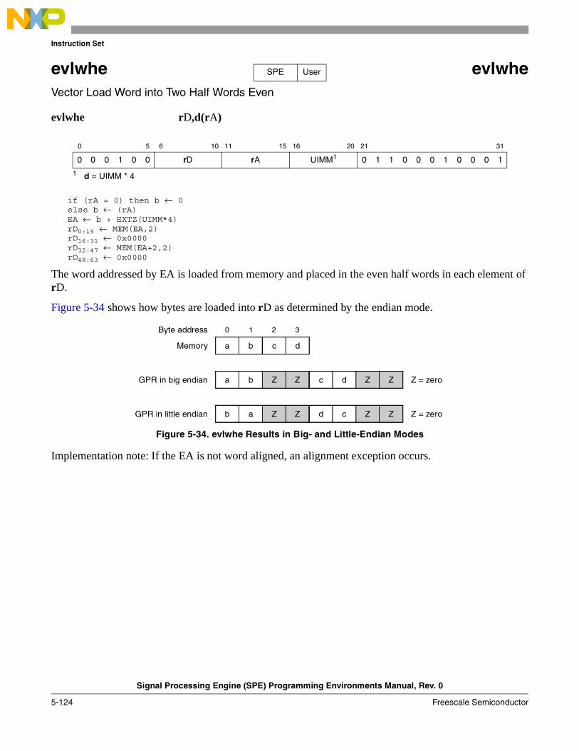
Instruction Set
Signal Processing Engine (SPE) Programming Environments Manual, Rev. 0
5-124 Freescale Semiconductor
evlwhe evlwheVector Load Word into Two Half Words Even
evlwhe rD,d(rA)
if (rA = 0) then b ← 0else b ← (rA)EA ← b + EXTZ(UIMM*4)rD0:15 ← MEM(EA,2)rD16:31 ← 0x0000rD32:47 ← MEM(EA+2,2)rD48:63 ← 0x0000
The word addressed by EA is loaded from memory and placed in the even half words in each element of rD.
Figure 5-34 shows how bytes are loaded into rD as determined by the endian mode.
Figure 5-34. evlwhe Results in Big- and Little-Endian Modes
Implementation note: If the EA is not word aligned, an alignment exception occurs.
0 5 6 10 11 15 16 20 21 31
0 0 0 1 0 0 rD rA UIMM1
1 d = UIMM * 4
0 1 1 0 0 0 1 0 0 0 1
SPE User
c d
0 1 2 3
a b
Z Z c d Za b Z
Z Z d c Zb a Z
Memory
GPR in big endian
GPR in little endian
Byte address
Z = zero
Z = zero
Instruction Set
Signal Processing Engine (SPE) Programming Environments Manual, Rev. 0
Freescale Semiconductor 5-125
evlwhex evlwhexVector Load Word into Two Half Words Even Indexed
evlwhex rD,rA,rB
if (rA = 0) then b ← 0else b ← (rA)EA ← b + (rB)rD0:15 ← MEM(EA,2)rD16:31 ← 0x0000rD32:47 ← MEM(EA+2,2)rD48:63 ← 0x0000
The word addressed by EA is loaded from memory and placed in the even half words in each element of rD.
Figure 5-35 shows how bytes are loaded into rD as determined by the endian mode.
Figure 5-35. evlwhex Results in Big- and Little-Endian Modes
Implementation note: If the EA is not word aligned, an alignment exception occurs.
0 5 6 10 11 15 16 20 21 31
0 0 0 1 0 0 rD rA rB 0 1 1 0 0 0 1 0 0 0 0
SPE User
c d
0 1 2 3
a b
Z Z c d Za b Z
Z Z d c Zb a Z
Memory
GPR in big endian
GPR in little endian
Byte address
Z = zero
Z = zero
Instruction Set
Signal Processing Engine (SPE) Programming Environments Manual, Rev. 0
5-126 Freescale Semiconductor
evlwhos evlwhosVector Load Word into Two Half Words Odd Signed (with sign extension)
evlwhos rD,d(rA)
if (rA = 0) then b ← 0else b ← (rA)EA ← b + EXTZ(UIMM*4)rD0:31 ← EXTS(MEM(EA,2))rD32:63 ← EXTS(MEM(EA+2,2))
The word addressed by EA is loaded from memory and placed in the odd half words sign extended in each element of rD.
Figure 5-36 shows how bytes are loaded into rD as determined by the endian mode.
Figure 5-36. evlwhos Results in Big- and Little-Endian Modes
In big-endian memory, the most significant bits of a and c are sign extended. In little-endian memory, the most significant bits of b and d are sign extended.
Implementation note: If the EA is not word aligned, an alignment exception occurs.
0 5 6 10 11 15 16 20 21 31
0 0 0 1 0 0 rD rA UIMM1
1 d = UIMM * 4
0 1 1 0 0 0 1 0 1 1 1
SPE User
c d
0 1 2 3
a b
a b S S dS S c
b a S S cS S d
Memory
GPR in big endian
GPR in little endian
Byte address
S = sign
S = sign
Instruction Set
Signal Processing Engine (SPE) Programming Environments Manual, Rev. 0
Freescale Semiconductor 5-127
evlwhosx evlwhosxVector Load Word into Two Half Words Odd Signed Indexed (with sign extension)
evlwhosx rD,rA,rB
if (rA = 0) then b ← 0else b ← (rA)EA ← b + (rB)rD0:31 ← EXTS(MEM(EA,2))rD32:63 ← EXTS(MEM(EA+2,2))
The word addressed by EA is loaded from memory and placed in the odd half words sign extended in each element of rD.
Figure 5-37 shows how bytes are loaded into rD as determined by the endian mode.
Figure 5-37. evlwhosx Results in Big- and Little-Endian Modes
In big-endian memory, the most significant bits of a and c are sign extended. In little-endian memory, the most significant bits of b and d are sign extended.
Implementation note: If the EA is not word aligned, an alignment exception occurs.
0 5 6 10 11 15 16 20 21 31
0 0 0 1 0 0 rD rA rB 0 1 1 0 0 0 1 0 1 1 0
SPE User
c d
0 1 2 3
a b
a b S S dS S c
b a S S cS S d
Memory
GPR in big endian
GPR in little endian
Byte address
S = sign
S = sign
Instruction Set
Signal Processing Engine (SPE) Programming Environments Manual, Rev. 0
5-128 Freescale Semiconductor
evlwhou evlwhouVector Load Word into Two Half Words Odd Unsigned (zero-extended)
evlwhou rD,d(rA)
if (rA = 0) then b ← 0else b ← (rA)EA ← b + EXTZ(UIMM*4)rD0:15 ← 0x0000rD16:31 ← MEM(EA,2)rD32:47 ← 0x0000rD48:63 ← MEM(EA+2,2)
The word addressed by EA is loaded from memory and placed in the odd half words zero extended in each element of rD.
Figure 5-38 shows how bytes are loaded into rD as determined by the endian mode.
Figure 5-38. evlwhou Results in Big- and Little-Endian Modes
Implementation note: If the EA is not word aligned, an alignment exception occurs.
0 5 6 10 11 15 16 20 21 31
0 0 0 1 0 0 rD rA UIMM1
1 d = UIMM * 4
0 1 1 0 0 0 1 0 1 0 1
SPE User
c d
0 1 2 3
a b
a b Z Z dZ Z c
b a Z Z cZ Z d
Memory
GPR in big endian
GPR in little endian
Byte address
Z = zero
Z = zero
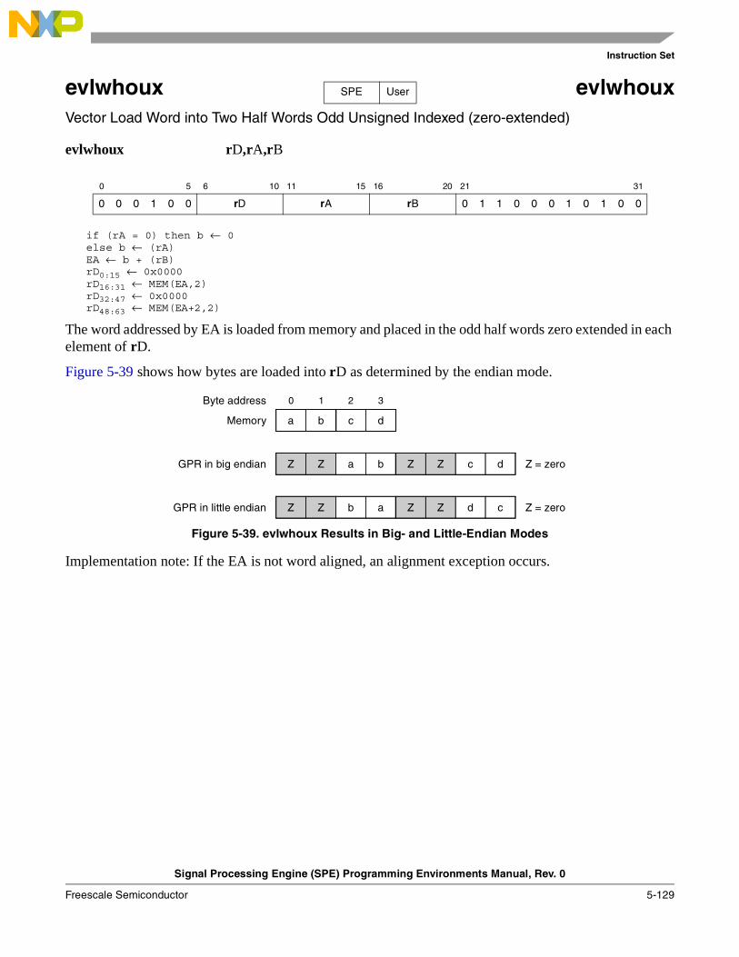
Instruction Set
Signal Processing Engine (SPE) Programming Environments Manual, Rev. 0
Freescale Semiconductor 5-129
evlwhoux evlwhouxVector Load Word into Two Half Words Odd Unsigned Indexed (zero-extended)
evlwhoux rD,rA,rB
if (rA = 0) then b ← 0else b ← (rA)EA ← b + (rB)rD0:15 ← 0x0000rD16:31 ← MEM(EA,2)rD32:47 ← 0x0000rD48:63 ← MEM(EA+2,2)
The word addressed by EA is loaded from memory and placed in the odd half words zero extended in each element of rD.
Figure 5-39 shows how bytes are loaded into rD as determined by the endian mode.
Figure 5-39. evlwhoux Results in Big- and Little-Endian Modes
Implementation note: If the EA is not word aligned, an alignment exception occurs.
0 5 6 10 11 15 16 20 21 31
0 0 0 1 0 0 rD rA rB 0 1 1 0 0 0 1 0 1 0 0
SPE User
c d
0 1 2 3
a b
a b Z Z dZ Z c
b a Z Z cZ Z d
Memory
GPR in big endian
GPR in little endian
Byte address
Z = zero
Z = zero
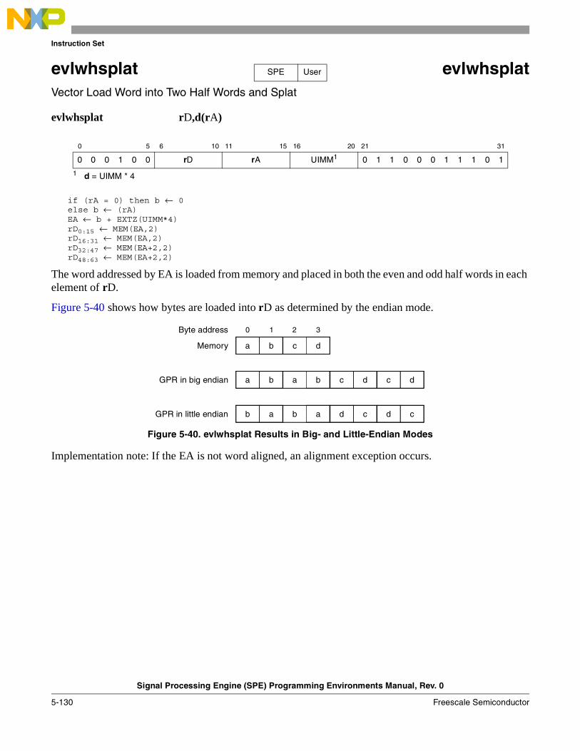
Instruction Set
Signal Processing Engine (SPE) Programming Environments Manual, Rev. 0
5-130 Freescale Semiconductor
evlwhsplat evlwhsplatVector Load Word into Two Half Words and Splat
evlwhsplat rD,d(rA)
if (rA = 0) then b ← 0else b ← (rA)EA ← b + EXTZ(UIMM*4)rD0:15 ← MEM(EA,2)rD16:31 ← MEM(EA,2)rD32:47 ← MEM(EA+2,2)rD48:63 ← MEM(EA+2,2)
The word addressed by EA is loaded from memory and placed in both the even and odd half words in each element of rD.
Figure 5-40 shows how bytes are loaded into rD as determined by the endian mode.
Figure 5-40. evlwhsplat Results in Big- and Little-Endian Modes
Implementation note: If the EA is not word aligned, an alignment exception occurs.
0 5 6 10 11 15 16 20 21 31
0 0 0 1 0 0 rD rA UIMM1
1 d = UIMM * 4
0 1 1 0 0 0 1 1 1 0 1
SPE User
c d
0 1 2 3
a b
a b c d da b c
b a d c cb a d
Memory
GPR in big endian
GPR in little endian
Byte address
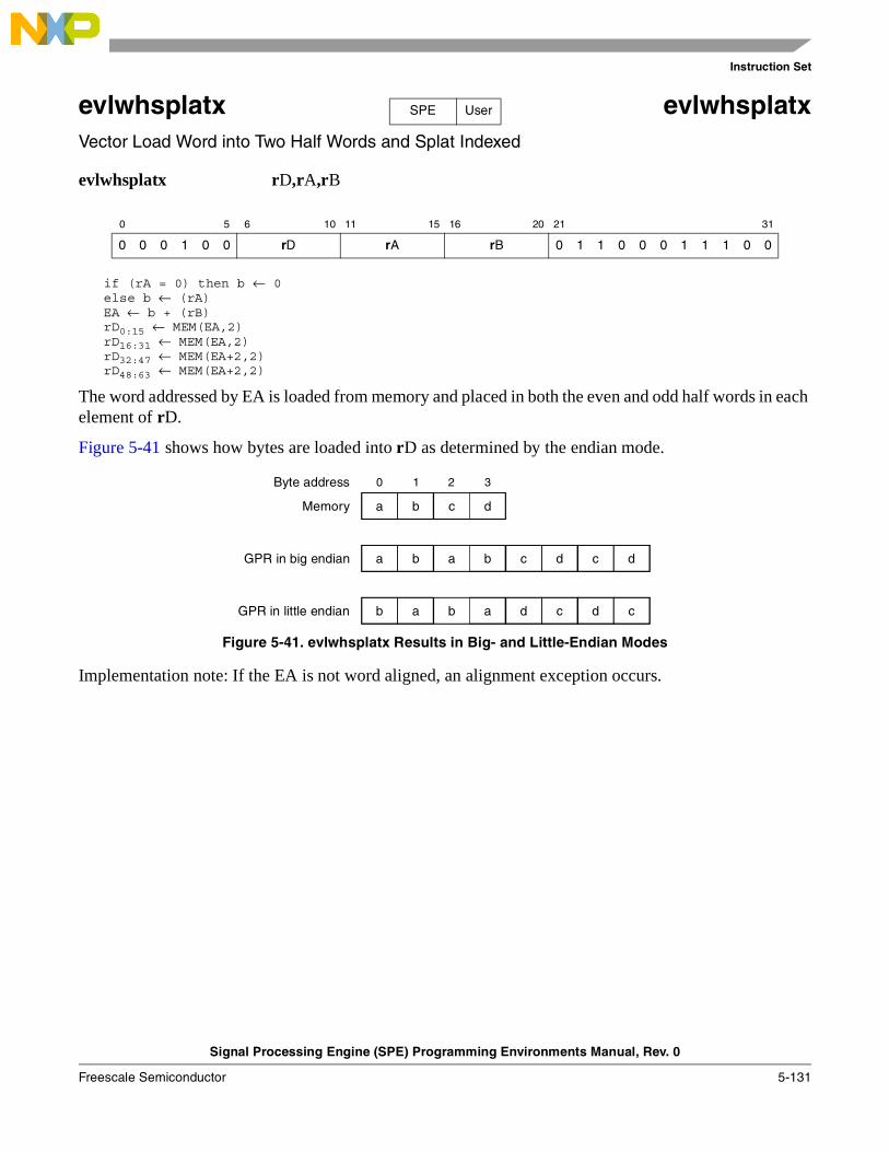
Instruction Set
Signal Processing Engine (SPE) Programming Environments Manual, Rev. 0
Freescale Semiconductor 5-131
evlwhsplatx evlwhsplatxVector Load Word into Two Half Words and Splat Indexed
evlwhsplatx rD,rA,rB
if (rA = 0) then b ← 0else b ← (rA)EA ← b + (rB)rD0:15 ← MEM(EA,2)rD16:31 ← MEM(EA,2)rD32:47 ← MEM(EA+2,2)rD48:63 ← MEM(EA+2,2)
The word addressed by EA is loaded from memory and placed in both the even and odd half words in each element of rD.
Figure 5-41 shows how bytes are loaded into rD as determined by the endian mode.
Figure 5-41. evlwhsplatx Results in Big- and Little-Endian Modes
Implementation note: If the EA is not word aligned, an alignment exception occurs.
0 5 6 10 11 15 16 20 21 31
0 0 0 1 0 0 rD rA rB 0 1 1 0 0 0 1 1 1 0 0
SPE User
c d
0 1 2 3
a b
a b c d da b c
b a d c cb a d
Memory
GPR in big endian
GPR in little endian
Byte address
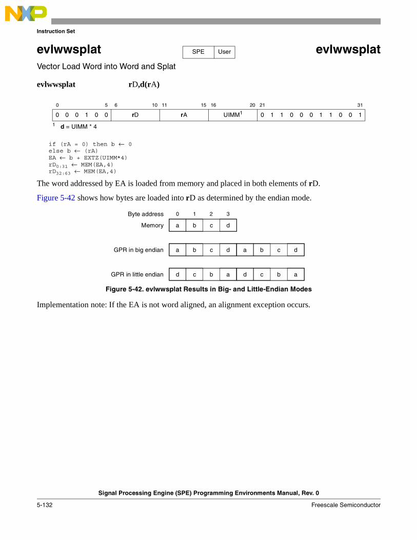
Instruction Set
Signal Processing Engine (SPE) Programming Environments Manual, Rev. 0
5-132 Freescale Semiconductor
evlwwsplat evlwwsplatVector Load Word into Word and Splat
evlwwsplat rD,d(rA)
if (rA = 0) then b ← 0else b ← (rA)EA ← b + EXTZ(UIMM*4)rD0:31 ← MEM(EA,4)rD32:63 ← MEM(EA,4)
The word addressed by EA is loaded from memory and placed in both elements of rD.
Figure 5-42 shows how bytes are loaded into rD as determined by the endian mode.
Figure 5-42. evlwwsplat Results in Big- and Little-Endian Modes
Implementation note: If the EA is not word aligned, an alignment exception occurs.
0 5 6 10 11 15 16 20 21 31
0 0 0 1 0 0 rD rA UIMM1
1 d = UIMM * 4
0 1 1 0 0 0 1 1 0 0 1
SPE User
c d
0 1 2 3
a b
c d a b da b c
b a d c ad c b
Memory
GPR in big endian
GPR in little endian
Byte address
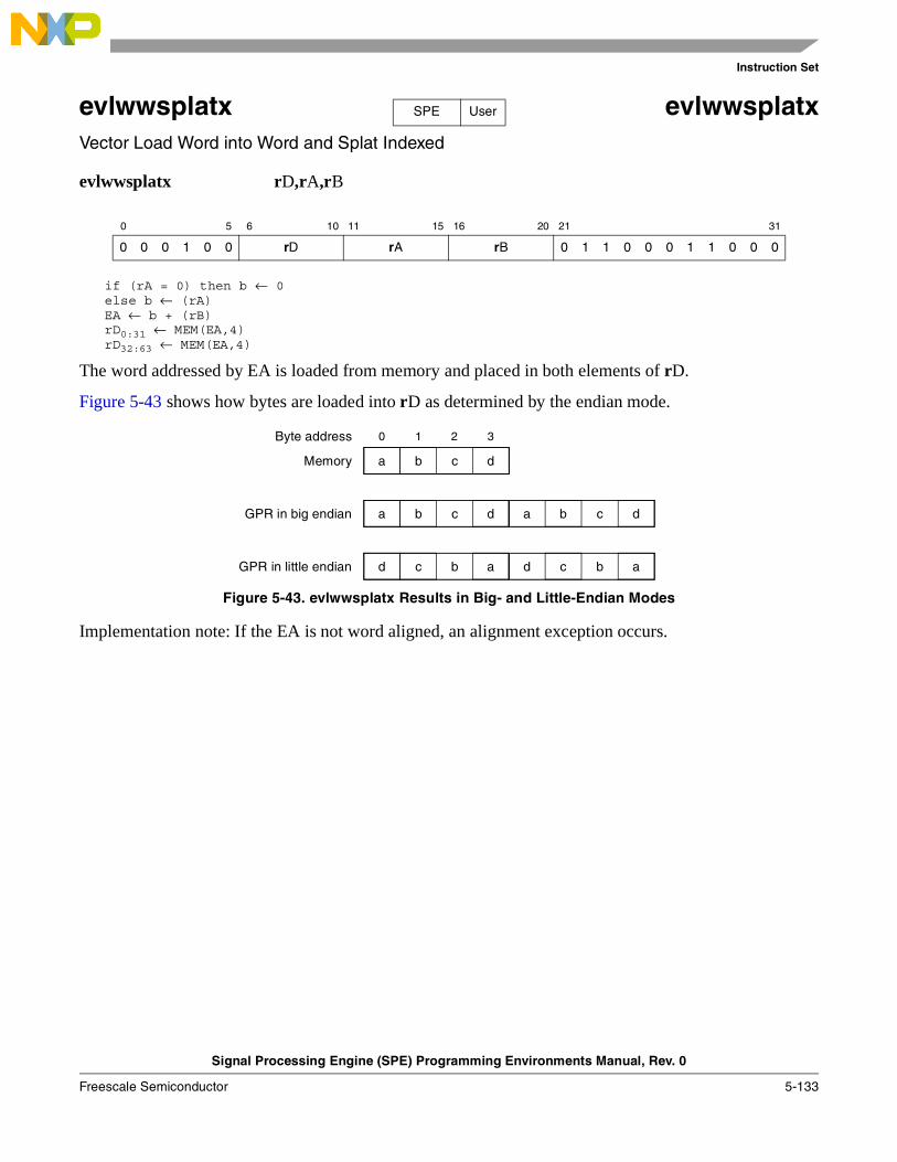
Instruction Set
Signal Processing Engine (SPE) Programming Environments Manual, Rev. 0
Freescale Semiconductor 5-133
evlwwsplatx evlwwsplatxVector Load Word into Word and Splat Indexed
evlwwsplatx rD,rA,rB
if (rA = 0) then b ← 0else b ← (rA)EA ← b + (rB)rD0:31 ← MEM(EA,4)rD32:63 ← MEM(EA,4)
The word addressed by EA is loaded from memory and placed in both elements of rD.
Figure 5-43 shows how bytes are loaded into rD as determined by the endian mode.
Figure 5-43. evlwwsplatx Results in Big- and Little-Endian Modes
Implementation note: If the EA is not word aligned, an alignment exception occurs.
0 5 6 10 11 15 16 20 21 31
0 0 0 1 0 0 rD rA rB 0 1 1 0 0 0 1 1 0 0 0
SPE User
c d
0 1 2 3
a b
c d a b da b c
b a d c ad c b
Memory
GPR in big endian
GPR in little endian
Byte address
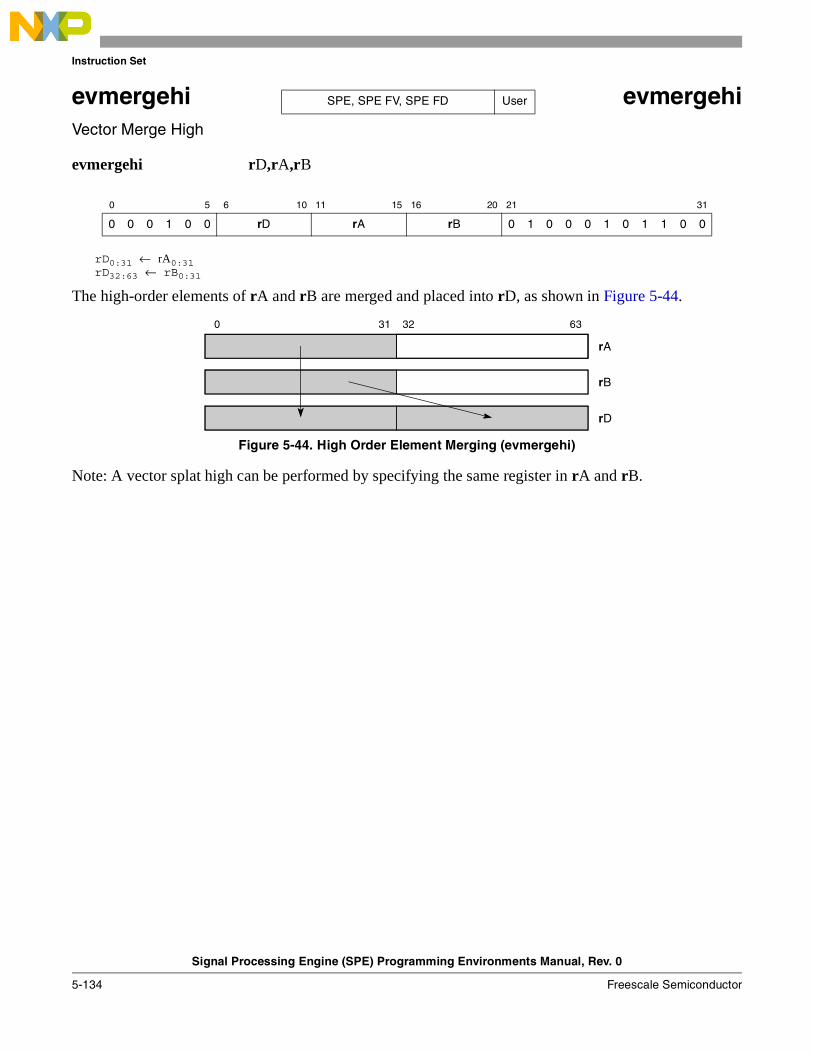
Instruction Set
Signal Processing Engine (SPE) Programming Environments Manual, Rev. 0
5-134 Freescale Semiconductor
evmergehi evmergehiVector Merge High
evmergehi rD,rA,rB
rD0:31 ← rA0:31rD32:63 ← rB0:31
The high-order elements of rA and rB are merged and placed into rD, as shown in Figure 5-44.
Figure 5-44. High Order Element Merging (evmergehi)
Note: A vector splat high can be performed by specifying the same register in rA and rB.
0 5 6 10 11 15 16 20 21 31
0 0 0 1 0 0 rD rA rB 0 1 0 0 0 1 0 1 1 0 0
SPE, SPE FV, SPE FD User
0 31 32 63
rA
rB
rD
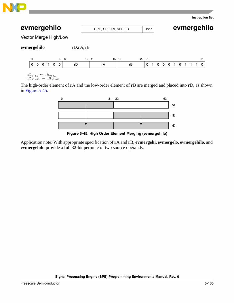
Instruction Set
Signal Processing Engine (SPE) Programming Environments Manual, Rev. 0
Freescale Semiconductor 5-135
evmergehilo evmergehiloVector Merge High/Low
evmergehilo rD,rA,rB
rD0:31 ← rA0:31rD32:63 ← rB32:63
The high-order element of rA and the low-order element of rB are merged and placed into rD, as shown in Figure 5-45.
Figure 5-45. High Order Element Merging (evmergehilo)
Application note: With appropriate specification of rA and rB, evmergehi, evmergelo, evmergehilo, and evmergelohi provide a full 32-bit permute of two source operands.
0 5 6 10 11 15 16 20 21 31
0 0 0 1 0 0 rD rA rB 0 1 0 0 0 1 0 1 1 1 0
SPE, SPE FV, SPE FD User
0 31 32 63
rA
rB
rD
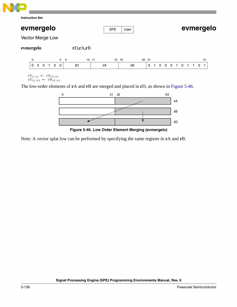
Instruction Set
Signal Processing Engine (SPE) Programming Environments Manual, Rev. 0
5-136 Freescale Semiconductor
evmergelo evmergeloVector Merge Low
evmergelo rD,rA,rB
rD0:31 ← rA32:63rD32:63 ← rB32:63
The low-order elements of rA and rB are merged and placed in rD, as shown in Figure 5-46.
Figure 5-46. Low Order Element Merging (evmergelo)
Note: A vector splat low can be performed by specifying the same register in rA and rB.
0 5 6 10 11 15 16 20 21 31
0 0 0 1 0 0 rD rA rB 0 1 0 0 0 1 0 1 1 0 1
SPE User
0 31 32 63
rA
rB
rD
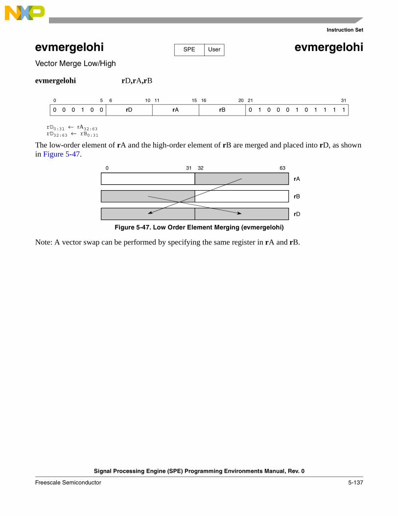
Instruction Set
Signal Processing Engine (SPE) Programming Environments Manual, Rev. 0
Freescale Semiconductor 5-137
evmergelohi evmergelohiVector Merge Low/High
evmergelohi rD,rA,rB
rD0:31 ← rA32:63rD32:63 ← rB0:31
The low-order element of rA and the high-order element of rB are merged and placed into rD, as shown in Figure 5-47.
Figure 5-47. Low Order Element Merging (evmergelohi)
Note: A vector swap can be performed by specifying the same register in rA and rB.
0 5 6 10 11 15 16 20 21 31
0 0 0 1 0 0 rD rA rB 0 1 0 0 0 1 0 1 1 1 1
SPE User
0 31 32 63
rA
rB
rD
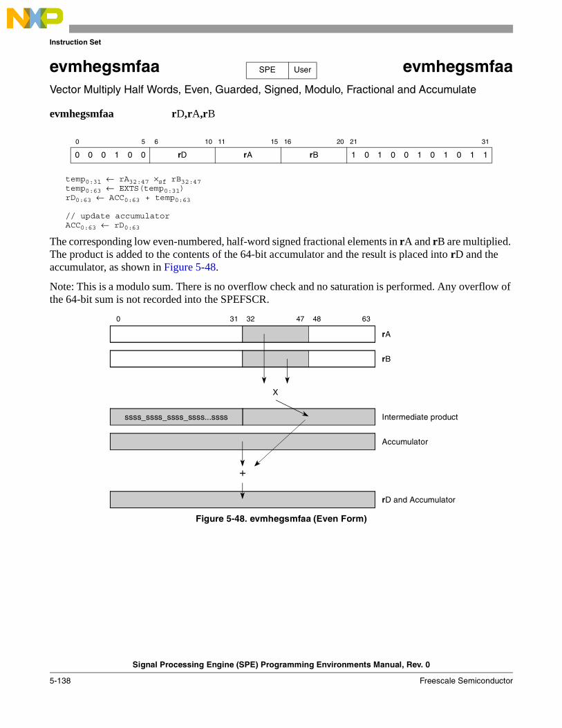
Instruction Set
Signal Processing Engine (SPE) Programming Environments Manual, Rev. 0
5-138 Freescale Semiconductor
evmhegsmfaa evmhegsmfaaVector Multiply Half Words, Even, Guarded, Signed, Modulo, Fractional and Accumulate
evmhegsmfaa rD,rA,rB
temp0:31 ← rA32:47 ×sf rB32:47temp0:63 ← EXTS(temp0:31) rD0:63 ← ACC0:63 + temp0:63
// update accumulatorACC0:63 ← rD0:63
The corresponding low even-numbered, half-word signed fractional elements in rA and rB are multiplied. The product is added to the contents of the 64-bit accumulator and the result is placed into rD and the accumulator, as shown in Figure 5-48.
Note: This is a modulo sum. There is no overflow check and no saturation is performed. Any overflow of the 64-bit sum is not recorded into the SPEFSCR.
Figure 5-48. evmhegsmfaa (Even Form)
0 5 6 10 11 15 16 20 21 31
0 0 0 1 0 0 rD rA rB 1 0 1 0 0 1 0 1 0 1 1
SPE User
47 480 31 32 63
Intermediate product
Accumulator
rB
X
+
rD and Accumulator
rA
ssss_ssss_ssss_ssss...ssss
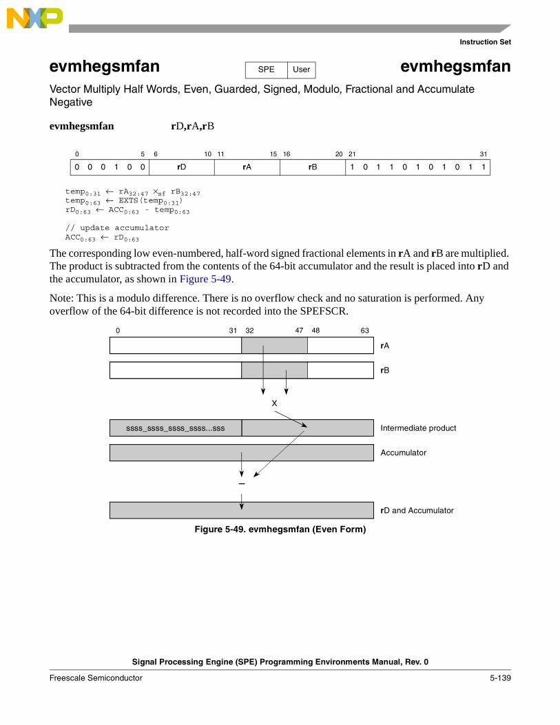
Instruction Set
Signal Processing Engine (SPE) Programming Environments Manual, Rev. 0
Freescale Semiconductor 5-139
evmhegsmfan evmhegsmfanVector Multiply Half Words, Even, Guarded, Signed, Modulo, Fractional and Accumulate Negative
evmhegsmfan rD,rA,rB
temp0:31 ← rA32:47 ×sf rB32:47temp0:63 ← EXTS(temp0:31)rD0:63 ← ACC0:63 - temp0:63
// update accumulatorACC0:63 ← rD0:63
The corresponding low even-numbered, half-word signed fractional elements in rA and rB are multiplied. The product is subtracted from the contents of the 64-bit accumulator and the result is placed into rD and the accumulator, as shown in Figure 5-49.
Note: This is a modulo difference. There is no overflow check and no saturation is performed. Any overflow of the 64-bit difference is not recorded into the SPEFSCR.
Figure 5-49. evmhegsmfan (Even Form)
0 5 6 10 11 15 16 20 21 31
0 0 0 1 0 0 rD rA rB 1 0 1 1 0 1 0 1 0 1 1
SPE User
47 480 31 32 63
Intermediate product
Accumulator
rB
X
–
rD and Accumulator
rA
ssss_ssss_ssss_ssss...sss
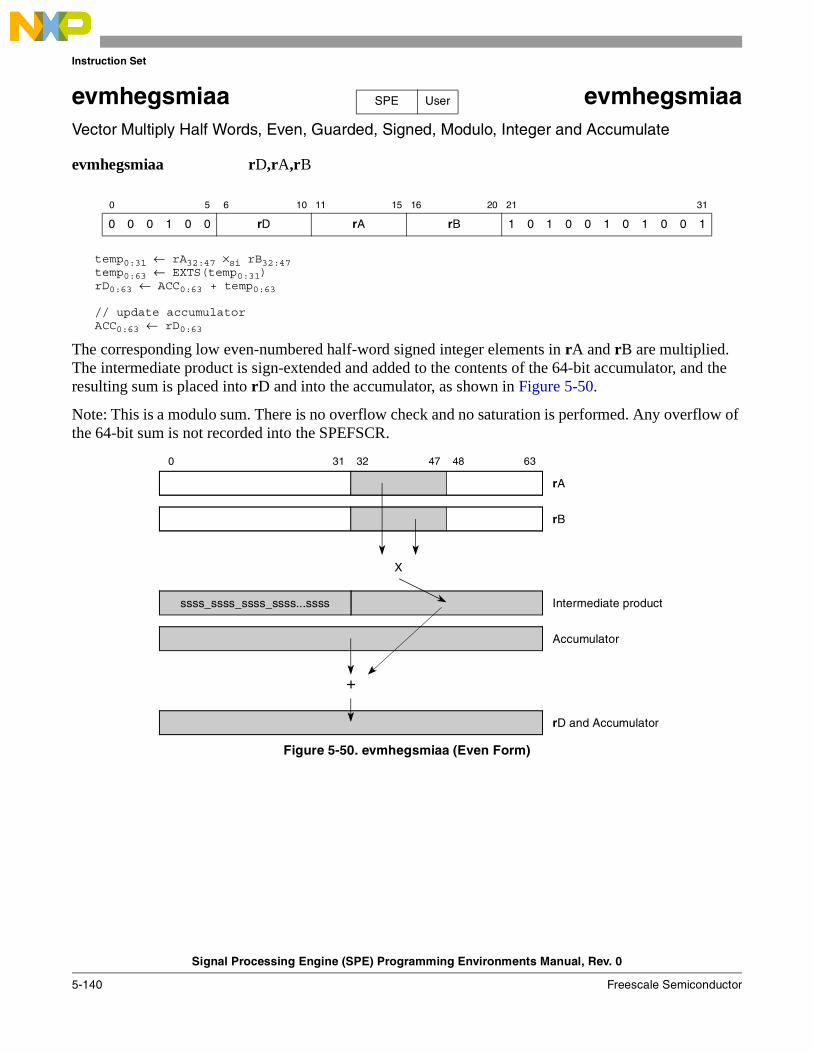
Instruction Set
Signal Processing Engine (SPE) Programming Environments Manual, Rev. 0
5-140 Freescale Semiconductor
evmhegsmiaa evmhegsmiaaVector Multiply Half Words, Even, Guarded, Signed, Modulo, Integer and Accumulate
evmhegsmiaa rD,rA,rB
temp0:31 ← rA32:47 ×si rB32:47temp0:63 ← EXTS(temp0:31)rD0:63 ← ACC0:63 + temp0:63
// update accumulatorACC0:63 ← rD0:63
The corresponding low even-numbered half-word signed integer elements in rA and rB are multiplied. The intermediate product is sign-extended and added to the contents of the 64-bit accumulator, and the resulting sum is placed into rD and into the accumulator, as shown in Figure 5-50.
Note: This is a modulo sum. There is no overflow check and no saturation is performed. Any overflow of the 64-bit sum is not recorded into the SPEFSCR.
Figure 5-50. evmhegsmiaa (Even Form)
0 5 6 10 11 15 16 20 21 31
0 0 0 1 0 0 rD rA rB 1 0 1 0 0 1 0 1 0 0 1
SPE User
47 480 31 32 63
Intermediate product
Accumulator
rB
X
+
rD and Accumulator
rA
ssss_ssss_ssss_ssss...ssss
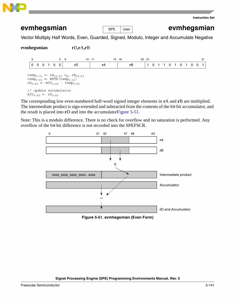
Instruction Set
Signal Processing Engine (SPE) Programming Environments Manual, Rev. 0
Freescale Semiconductor 5-141
evmhegsmian evmhegsmianVector Multiply Half Words, Even, Guarded, Signed, Modulo, Integer and Accumulate Negative
evmhegsmian rD,rA,rB
temp0:31 ← rA32:47 ×si rB32:47temp0:63 ← EXTS(temp0:31)rD0:63 ← ACC0:63 - temp0:63
// update accumulatorACC0:63 ← rD0:63
The corresponding low even-numbered half-word signed integer elements in rA and rB are multiplied. The intermediate product is sign-extended and subtracted from the contents of the 64-bit accumulator, and the result is placed into rD and into the accumulatorFigure 5-51.
Note: This is a modulo difference. There is no check for overflow and no saturation is performed. Any overflow of the 64-bit difference is not recorded into the SPEFSCR.
Figure 5-51. evmhegsmian (Even Form)
0 5 6 10 11 15 16 20 21 31
0 0 0 1 0 0 rD rA rB 1 0 1 1 0 1 0 1 0 0 1
SPE User
47 480 31 32 63
Intermediate product
Accumulator
rB
X
–
rD and Accumulator
rA
ssss_ssss_ssss_ssss...ssss
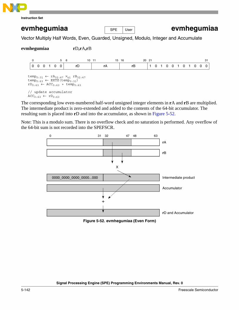
Instruction Set
Signal Processing Engine (SPE) Programming Environments Manual, Rev. 0
5-142 Freescale Semiconductor
evmhegumiaa evmhegumiaaVector Multiply Half Words, Even, Guarded, Unsigned, Modulo, Integer and Accumulate
evmhegumiaa rD,rA,rB
temp0:31 ← rA32:47 ×ui rB32:47temp0:63 ← EXTZ(temp0:31)rD0:63 ← ACC0:63 + temp0:63
// update accumulatorACC0:63 ← rD0:63
The corresponding low even-numbered half-word unsigned integer elements in rA and rB are multiplied. The intermediate product is zero-extended and added to the contents of the 64-bit accumulator. The resulting sum is placed into rD and into the accumulator, as shown in Figure 5-52.
Note: This is a modulo sum. There is no overflow check and no saturation is performed. Any overflow of the 64-bit sum is not recorded into the SPEFSCR.
Figure 5-52. evmhegumiaa (Even Form)
0 5 6 10 11 15 16 20 21 31
0 0 0 1 0 0 rD rA rB 1 0 1 0 0 1 0 1 0 0 0
SPE User
47 480 31 32 63
Intermediate product
Accumulator
rB
X
+
rD and Accumulator
rA
0000_0000_0000_0000...000
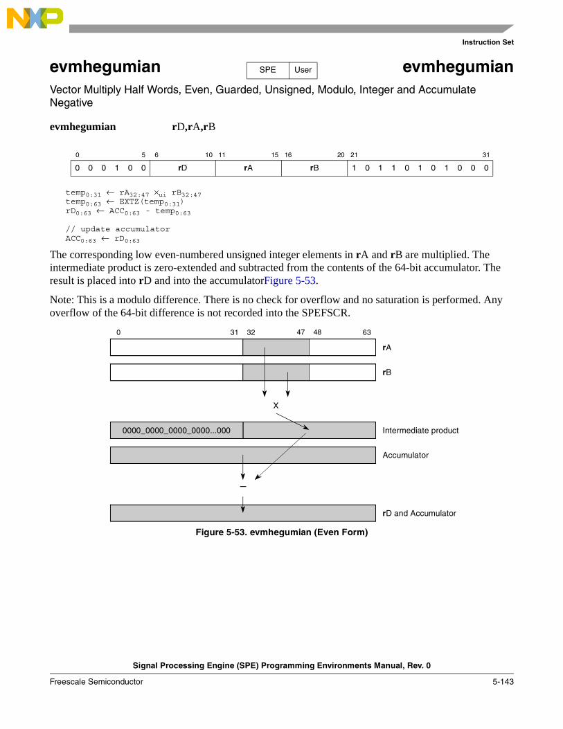
Instruction Set
Signal Processing Engine (SPE) Programming Environments Manual, Rev. 0
Freescale Semiconductor 5-143
evmhegumian evmhegumianVector Multiply Half Words, Even, Guarded, Unsigned, Modulo, Integer and Accumulate Negative
evmhegumian rD,rA,rB
temp0:31 ← rA32:47 ×ui rB32:47temp0:63 ← EXTZ(temp0:31)rD0:63 ← ACC0:63 - temp0:63
// update accumulatorACC0:63 ← rD0:63
The corresponding low even-numbered unsigned integer elements in rA and rB are multiplied. The intermediate product is zero-extended and subtracted from the contents of the 64-bit accumulator. The result is placed into rD and into the accumulatorFigure 5-53.
Note: This is a modulo difference. There is no check for overflow and no saturation is performed. Any overflow of the 64-bit difference is not recorded into the SPEFSCR.
Figure 5-53. evmhegumian (Even Form)
0 5 6 10 11 15 16 20 21 31
0 0 0 1 0 0 rD rA rB 1 0 1 1 0 1 0 1 0 0 0
SPE User
47 480 31 32 63
Intermediate product
Accumulator
rB
X
–
rD and Accumulator
rA
0000_0000_0000_0000...000
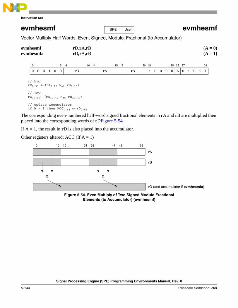
Instruction Set
Signal Processing Engine (SPE) Programming Environments Manual, Rev. 0
5-144 Freescale Semiconductor
evmhesmf evmhesmfVector Multiply Half Words, Even, Signed, Modulo, Fractional (to Accumulator)
evmhesmf rD,rA,rB (A = 0)evmhesmfa rD,rA,rB (A = 1)
// highrD0:31 ← (rA0:15 ×sf rB0:15)
// lowrD32:63← (rA32:47 ×sf rB32:47)
// update accumulatorif A = 1 then ACC0:63 ← rD0:63
The corresponding even-numbered half-word signed fractional elements in rA and rB are multiplied then placed into the corresponding words of rDFigure 5-54.
If A = 1, the result in rD is also placed into the accumulator.
Other registers altered: ACC (If A = 1)
Figure 5-54. Even Multiply of Two Signed Modulo FractionalElements (to Accumulator) (evmhesmf)
0 5 6 10 11 15 16 20 21 25 26 27 31
0 0 0 1 0 0 rD rA rB 1 0 0 0 0 A 0 1 0 1 1
SPE User
15 16 47 480 31 32 63
rA
rB
rD (and accumulator if evmhesmfa)
XX
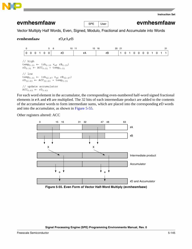
Instruction Set
Signal Processing Engine (SPE) Programming Environments Manual, Rev. 0
Freescale Semiconductor 5-145
evmhesmfaaw evmhesmfaawVector Multiply Half Words, Even, Signed, Modulo, Fractional and Accumulate into Words
evmhesmfaaw rD,rA,rB
// hightemp0:31 ← (rA0:15 ×sf rB0:15) rD0:31 ← ACC0:31 + temp0:31
// lowtemp0:31 ← (rA32:47 ×sf rB32:47) rD32:63 ← ACC32:63 + temp0:31
// update accumulatorACC0:63 ← rD0:63
For each word element in the accumulator, the corresponding even-numbered half-word signed fractional elements in rA and rB are multiplied. The 32 bits of each intermediate product are added to the contents of the accumulator words to form intermediate sums, which are placed into the corresponding rD words and into the accumulator, as shown in Figure 5-55.
Other registers altered: ACC
Figure 5-55. Even Form of Vector Half-Word Multiply (evmhesmfaaw)
0 5 6 10 11 15 16 20 21 31
0 0 0 1 0 0 rD rA rB 1 0 1 0 0 0 0 1 0 1 1
SPE User
15 16 47 480 31 32 63
Intermediate product
Accumulator
rB
XX
++
rD and Accumulator
rA
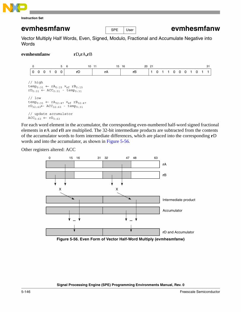
Instruction Set
Signal Processing Engine (SPE) Programming Environments Manual, Rev. 0
5-146 Freescale Semiconductor
evmhesmfanw evmhesmfanwVector Multiply Half Words, Even, Signed, Modulo, Fractional and Accumulate Negative into Words
evmhesmfanw rD,rA,rB
// hightemp0:31 ← rA0:15 ×sf rB0:15 rD0:31 ← ACC0:31 - temp0:31
// lowtemp0:31 ← rA32:47 ×sf rB32:47 rD32:63← ACC32:63 - temp0:31
// update accumulatorACC0:63 ← rD0:63
For each word element in the accumulator, the corresponding even-numbered half-word signed fractional elements in rA and rB are multiplied. The 32-bit intermediate products are subtracted from the contents of the accumulator words to form intermediate differences, which are placed into the corresponding rD words and into the accumulator, as shown in Figure 5-56.
Other registers altered: ACC
Figure 5-56. Even Form of Vector Half-Word Multiply (evmhesmfanw)
0 5 6 10 11 15 16 20 21 31
0 0 0 1 0 0 rD rA rB 1 0 1 1 0 0 0 1 0 1 1
SPE User
15 16 47 480 31 32 63
Intermediate product
Accumulator
rB
XX
––
rD and Accumulator
rA
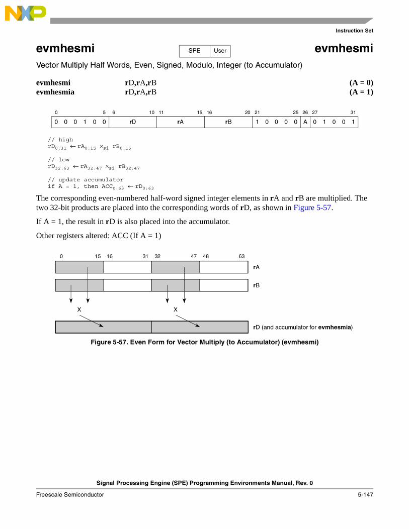
Instruction Set
Signal Processing Engine (SPE) Programming Environments Manual, Rev. 0
Freescale Semiconductor 5-147
evmhesmi evmhesmiVector Multiply Half Words, Even, Signed, Modulo, Integer (to Accumulator)
evmhesmi rD,rA,rB (A = 0)evmhesmia rD,rA,rB (A = 1)
// highrD0:31 ← rA0:15 ×si rB0:15
// lowrD32:63 ← rA32:47 ×si rB32:47
// update accumulatorif A = 1, then ACC0:63 ← rD0:63
The corresponding even-numbered half-word signed integer elements in rA and rB are multiplied. The two 32-bit products are placed into the corresponding words of rD, as shown in Figure 5-57.
If A = 1, the result in rD is also placed into the accumulator.
Other registers altered: ACC (If A = 1)
Figure 5-57. Even Form for Vector Multiply (to Accumulator) (evmhesmi)
0 5 6 10 11 15 16 20 21 25 26 27 31
0 0 0 1 0 0 rD rA rB 1 0 0 0 0 A 0 1 0 0 1
SPE User
15 16 47 480 31 32 63
rA
rB
rD (and accumulator for evmhesmia)
XX
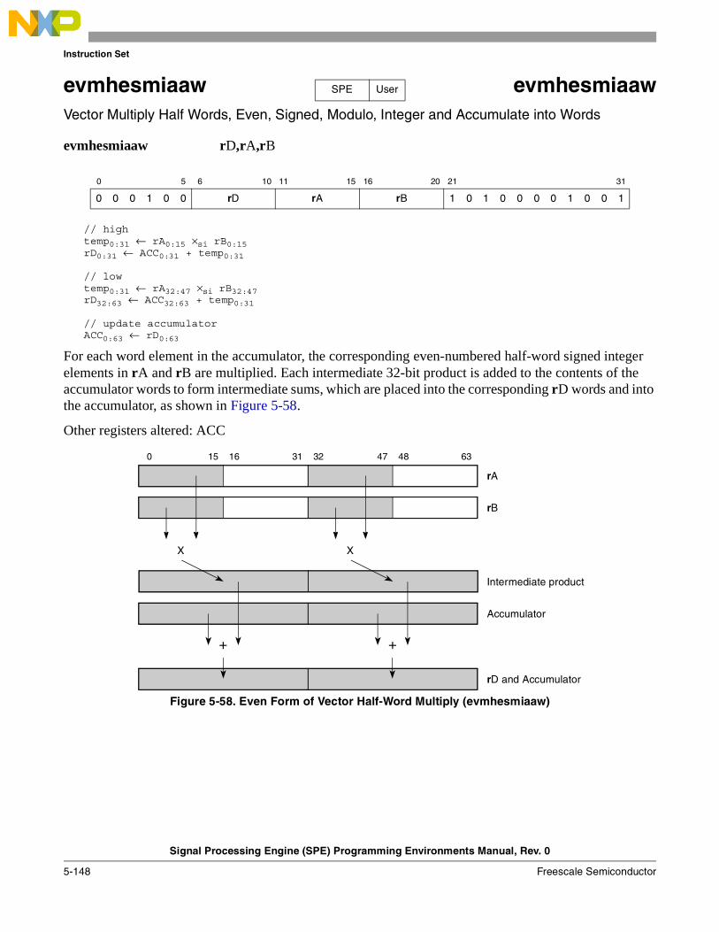
Instruction Set
Signal Processing Engine (SPE) Programming Environments Manual, Rev. 0
5-148 Freescale Semiconductor
evmhesmiaaw evmhesmiaawVector Multiply Half Words, Even, Signed, Modulo, Integer and Accumulate into Words
evmhesmiaaw rD,rA,rB
// hightemp0:31 ← rA0:15 ×si rB0:15 rD0:31 ← ACC0:31 + temp0:31
// lowtemp0:31 ← rA32:47 ×si rB32:47 rD32:63 ← ACC32:63 + temp0:31
// update accumulatorACC0:63 ← rD0:63
For each word element in the accumulator, the corresponding even-numbered half-word signed integer elements in rA and rB are multiplied. Each intermediate 32-bit product is added to the contents of the accumulator words to form intermediate sums, which are placed into the corresponding rD words and into the accumulator, as shown in Figure 5-58.
Other registers altered: ACC
Figure 5-58. Even Form of Vector Half-Word Multiply (evmhesmiaaw)
0 5 6 10 11 15 16 20 21 31
0 0 0 1 0 0 rD rA rB 1 0 1 0 0 0 0 1 0 0 1
SPE User
15 16 47 480 31 32 63
Intermediate product
Accumulator
rB
XX
++
rD and Accumulator
rA
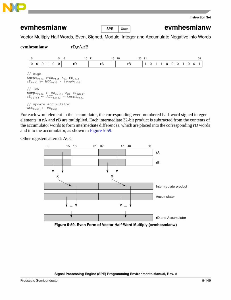
Instruction Set
Signal Processing Engine (SPE) Programming Environments Manual, Rev. 0
Freescale Semiconductor 5-149
evmhesmianw evmhesmianwVector Multiply Half Words, Even, Signed, Modulo, Integer and Accumulate Negative into Words
evmhesmianw rD,rA,rB
// hightemp00:31 ←rA0:15 ×si rB0:15 rD0:31 ← ACC0:31 - temp00:31
// lowtemp10:31 ← rA32:47 ×si rB32:47 rD32:63 ← ACC32:63 - temp10:31
// update accumulatorACC0:63 ← rD0:63
For each word element in the accumulator, the corresponding even-numbered half-word signed integer elements in rA and rB are multiplied. Each intermediate 32-bit product is subtracted from the contents of the accumulator words to form intermediate differences, which are placed into the corresponding rD words and into the accumulator, as shown in Figure 5-59.
Other registers altered: ACC
Figure 5-59. Even Form of Vector Half-Word Multiply (evmhesmianw)
0 5 6 10 11 15 16 20 21 31
0 0 0 1 0 0 rD rA rB 1 0 1 1 0 0 0 1 0 0 1
SPE User
15 16 47 480 31 32 63
Intermediate product
Accumulator
rB
XX
––
rD and Accumulator
rA
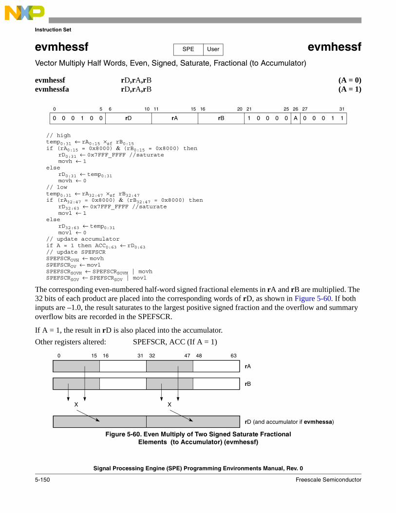
Instruction Set
Signal Processing Engine (SPE) Programming Environments Manual, Rev. 0
5-150 Freescale Semiconductor
evmhessf evmhessfVector Multiply Half Words, Even, Signed, Saturate, Fractional (to Accumulator)
evmhessf rD,rA,rB (A = 0)evmhessfa rD,rA,rB (A = 1)
// hightemp0:31 ← rA0:15 ×sf rB0:15 if (rA0:15 = 0x8000) & (rB0:15 = 0x8000) then
rD0:31 ← 0x7FFF_FFFF //saturate movh ← 1
elserD0:31 ← temp0:31movh ← 0
// lowtemp0:31 ← rA32:47 ×sf rB32:47 if (rA32:47 = 0x8000) & (rB32:47 = 0x8000) then
rD32:63 ← 0x7FFF_FFFF //saturatemovl ← 1
elserD32:63 ← temp0:31movl ← 0
// update accumulatorif A = 1 then ACC0:63 ← rD0:63// update SPEFSCRSPEFSCROVH ← movhSPEFSCROV ← movlSPEFSCRSOVH ← SPEFSCRSOVH | movhSPEFSCRSOV ← SPEFSCRSOV | movl
The corresponding even-numbered half-word signed fractional elements in rA and rB are multiplied. The 32 bits of each product are placed into the corresponding words of rD, as shown in Figure 5-60. If both inputs are –1.0, the result saturates to the largest positive signed fraction and the overflow and summary overflow bits are recorded in the SPEFSCR.
If A = 1, the result in rD is also placed into the accumulator.
Other registers altered: SPEFSCR, ACC (If A = 1)
Figure 5-60. Even Multiply of Two Signed Saturate FractionalElements (to Accumulator) (evmhessf)
0 5 6 10 11 15 16 20 21 25 26 27 31
0 0 0 1 0 0 rD rA rB 1 0 0 0 0 A 0 0 0 1 1
SPE User
15 16 47 480 31 32 63
rA
rB
rD (and accumulator if evmhessa)
XX

Instruction Set
Signal Processing Engine (SPE) Programming Environments Manual, Rev. 0
Freescale Semiconductor 5-151
evmhessfaaw evmhessfaawVector Multiply Half Words, Even, Signed, Saturate, Fractional and Accumulate into Words
evmhessfaaw rD,rA,rB
// hightemp0:31 ← rA0:15 ×sf rB0:15 if (rA0:15 = 0x8000) & (rB0:15 = 0x8000) then
temp0:31 ← 0x7FFF_FFFF //saturate movh ← 1
elsemovh ← 0
temp0:63 ← EXTS(ACC0:31) + EXTS(temp0:31)ovh ← (temp31 ⊕ temp32)rD0:31 ← SATURATE(ovh, temp31, 0x8000_0000, 0x7FFF_FFFF, temp32:63) // lowtemp0:31 ← rA32:47 ×sf rB32:47 if (rA32:47 = 0x8000) & (rB32:47 = 0x8000) then
temp0:31 ← 0x7FFF_FFFF //saturate movl ← 1
elsemovl ← 0
temp0:63 ← EXTS(ACC32:63) + EXTS(temp0:31)ovl ← (temp31 ⊕ temp32)rD32:63 ← SATURATE(ovl, temp31, 0x8000_0000, 0x7FFF_FFFF, temp32:63) // update accumulatorACC0:63 ← rD0:63// update SPEFSCRSPEFSCROVH ← movhSPEFSCROV ← movlSPEFSCRSOVH ← SPEFSCRSOVH | ovh | movhSPEFSCRSOV ← SPEFSCRSOV | ovl| movl
The corresponding even-numbered half-word signed fractional elements in rA and rB are multiplied producing a 32-bit product. If both inputs are –1.0, the result saturates to 0x7FFF_FFFF. Each 32-bit product is then added to the corresponding word in the accumulator, saturating if overflow or underflow occurs, and the result is placed in rD and the accumulator, as shown in Figure 5-61.
If there is an overflow or underflow from either the multiply or the addition, the overflow and summary overflow bits are recorded in the SPEFSCR.
Other registers altered: SPEFSCR ACC
Figure 5-61. Even Form of Vector Half-Word Multiply (evmhessfaaw)
0 5 6 10 11 15 16 20 21 31
0 0 0 1 0 0 rD rA rB 1 0 1 0 0 0 0 0 0 1 1
SPE User
15 16 47 480 31 32 63
Intermediate productAccumulator
rBXX
++
rD and Accumulator
rA
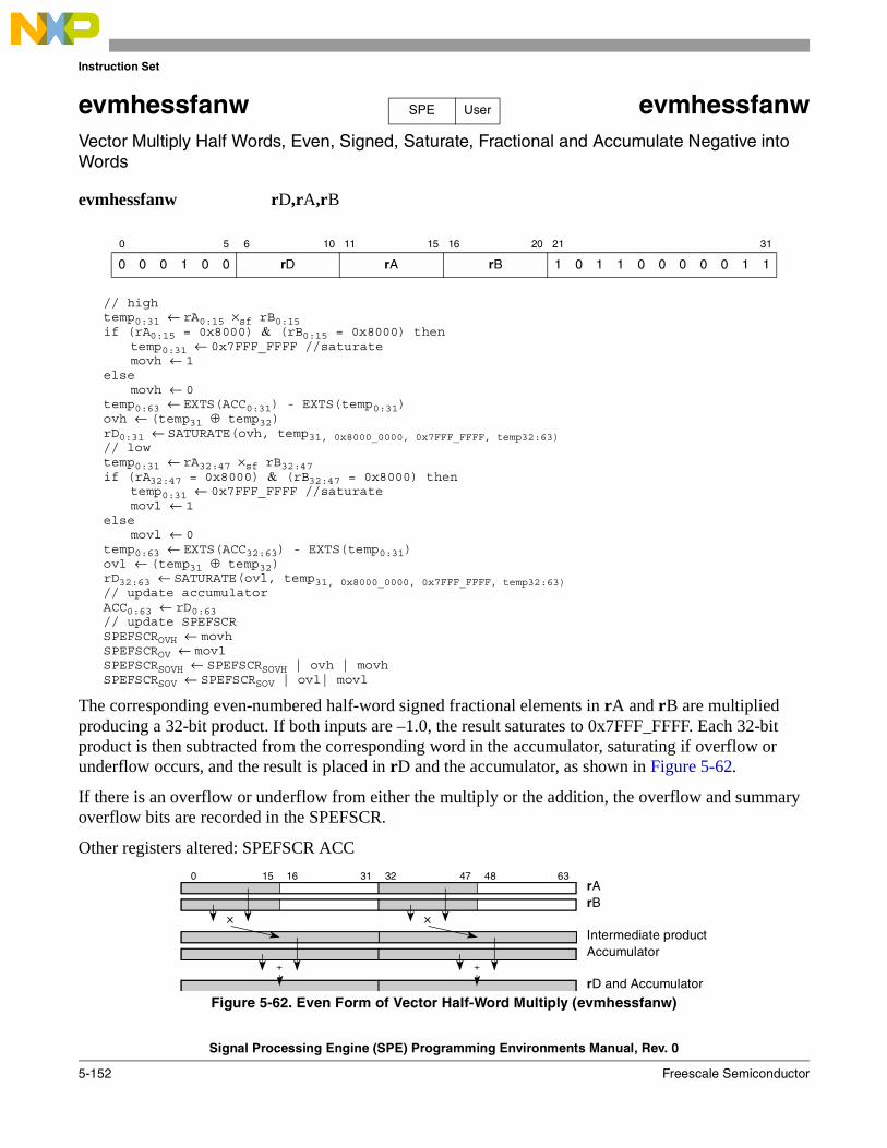
Instruction Set
Signal Processing Engine (SPE) Programming Environments Manual, Rev. 0
5-152 Freescale Semiconductor
evmhessfanw evmhessfanwVector Multiply Half Words, Even, Signed, Saturate, Fractional and Accumulate Negative into Words
evmhessfanw rD,rA,rB
// hightemp0:31 ← rA0:15 ×sf rB0:15 if (rA0:15 = 0x8000) & (rB0:15 = 0x8000) then
temp0:31 ← 0x7FFF_FFFF //saturate movh ← 1
elsemovh ← 0
temp0:63 ← EXTS(ACC0:31) - EXTS(temp0:31)ovh ← (temp31 ⊕ temp32)rD0:31 ← SATURATE(ovh, temp31, 0x8000_0000, 0x7FFF_FFFF, temp32:63) // lowtemp0:31 ← rA32:47 ×sf rB32:47 if (rA32:47 = 0x8000) & (rB32:47 = 0x8000) then
temp0:31 ← 0x7FFF_FFFF //saturate movl ← 1
elsemovl ← 0
temp0:63 ← EXTS(ACC32:63) - EXTS(temp0:31)ovl ← (temp31 ⊕ temp32)rD32:63 ← SATURATE(ovl, temp31, 0x8000_0000, 0x7FFF_FFFF, temp32:63) // update accumulatorACC0:63 ← rD0:63// update SPEFSCRSPEFSCROVH ← movhSPEFSCROV ← movlSPEFSCRSOVH ← SPEFSCRSOVH | ovh | movhSPEFSCRSOV ← SPEFSCRSOV | ovl| movl
The corresponding even-numbered half-word signed fractional elements in rA and rB are multiplied producing a 32-bit product. If both inputs are –1.0, the result saturates to 0x7FFF_FFFF. Each 32-bit product is then subtracted from the corresponding word in the accumulator, saturating if overflow or underflow occurs, and the result is placed in rD and the accumulator, as shown in Figure 5-62.
If there is an overflow or underflow from either the multiply or the addition, the overflow and summary overflow bits are recorded in the SPEFSCR.
Other registers altered: SPEFSCR ACC
Figure 5-62. Even Form of Vector Half-Word Multiply (evmhessfanw)
0 5 6 10 11 15 16 20 21 31
0 0 0 1 0 0 rD rA rB 1 0 1 1 0 0 0 0 0 1 1
SPE User
15 16 47 480 31 32 63
Intermediate productAccumulator
rBXX
++
rD and Accumulator
rA
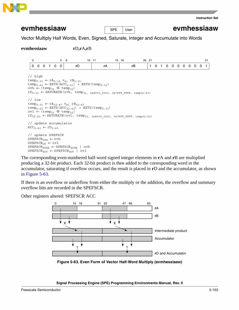
Instruction Set
Signal Processing Engine (SPE) Programming Environments Manual, Rev. 0
Freescale Semiconductor 5-153
evmhessiaaw evmhessiaawVector Multiply Half Words, Even, Signed, Saturate, Integer and Accumulate into Words
evmhessiaaw rD,rA,rB
// hightemp0:31 ← rA0:15 ×si rB0:15 temp0:63 ← EXTS(ACC0:31) + EXTS(temp0:31)ovh ← (temp31 ⊕ temp32)rD0:31 ← SATURATE(ovh, temp31, 0x8000_0000, 0x7FFF_FFFF, temp32:63)
// lowtemp0:31 ← rA32:47 ×si rB32:47 temp0:63 ← EXTS(ACC32:63) + EXTS(temp0:31)ovl ← (temp31 ⊕ temp32)rD32:63 ← SATURATE(ovl, temp31, 0x8000_0000, 0x7FFF_FFFF, temp32:63)
// update accumulatorACC0:63 ← rD0:63
// update SPEFSCRSPEFSCROVH ← ovhSPEFSCROV ← ovlSPEFSCRSOVH ← SPEFSCRSOVH | ovhSPEFSCRSOV ← SPEFSCRSOV | ovl
The corresponding even-numbered half-word signed integer elements in rA and rB are multiplied producing a 32-bit product. Each 32-bit product is then added to the corresponding word in the accumulator, saturating if overflow occurs, and the result is placed in rD and the accumulator, as shown in Figure 5-63.
If there is an overflow or underflow from either the multiply or the addition, the overflow and summary overflow bits are recorded in the SPEFSCR.
Other registers altered: SPEFSCR ACC
Figure 5-63. Even Form of Vector Half-Word Multiply (evmhessiaaw)
0 5 6 10 11 15 16 20 21 31
0 0 0 1 0 0 rD rA rB 1 0 1 0 0 0 0 0 0 0 1
SPE User
15 16 47 480 31 32 63
Intermediate product
Accumulator
rB
XX
++
rD and Accumulator
rA
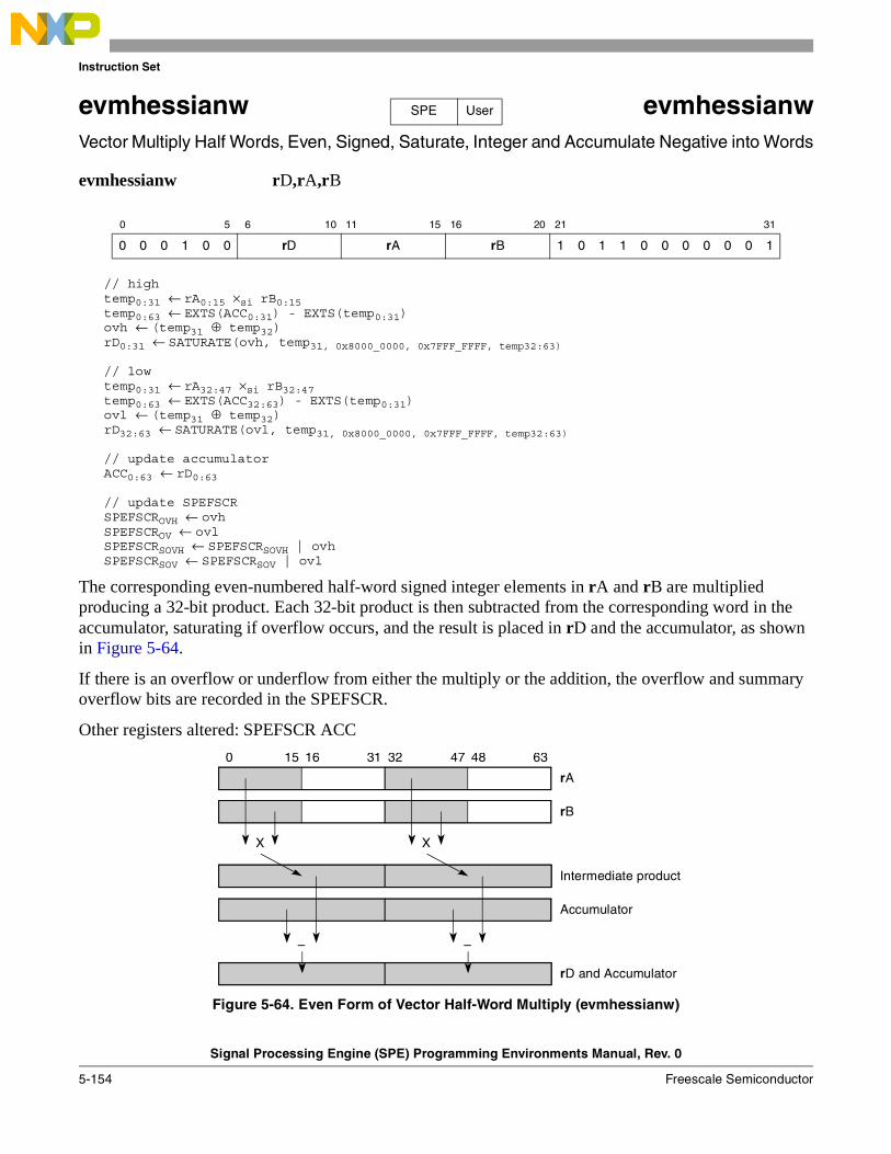
Instruction Set
Signal Processing Engine (SPE) Programming Environments Manual, Rev. 0
5-154 Freescale Semiconductor
evmhessianw evmhessianwVector Multiply Half Words, Even, Signed, Saturate, Integer and Accumulate Negative into Words
evmhessianw rD,rA,rB
// hightemp0:31 ← rA0:15 ×si rB0:15 temp0:63 ← EXTS(ACC0:31) - EXTS(temp0:31)ovh ← (temp31 ⊕ temp32)rD0:31 ← SATURATE(ovh, temp31, 0x8000_0000, 0x7FFF_FFFF, temp32:63)
// lowtemp0:31 ← rA32:47 ×si rB32:47 temp0:63 ← EXTS(ACC32:63) - EXTS(temp0:31)ovl ← (temp31 ⊕ temp32)rD32:63 ← SATURATE(ovl, temp31, 0x8000_0000, 0x7FFF_FFFF, temp32:63)
// update accumulatorACC0:63 ← rD0:63
// update SPEFSCRSPEFSCROVH ← ovhSPEFSCROV ← ovlSPEFSCRSOVH ← SPEFSCRSOVH | ovhSPEFSCRSOV ← SPEFSCRSOV | ovl
The corresponding even-numbered half-word signed integer elements in rA and rB are multiplied producing a 32-bit product. Each 32-bit product is then subtracted from the corresponding word in the accumulator, saturating if overflow occurs, and the result is placed in rD and the accumulator, as shown in Figure 5-64.
If there is an overflow or underflow from either the multiply or the addition, the overflow and summary overflow bits are recorded in the SPEFSCR.
Other registers altered: SPEFSCR ACC
Figure 5-64. Even Form of Vector Half-Word Multiply (evmhessianw)
0 5 6 10 11 15 16 20 21 31
0 0 0 1 0 0 rD rA rB 1 0 1 1 0 0 0 0 0 0 1
SPE User
15 16 47 480 31 32 63
Intermediate product
Accumulator
rB
XX
––
rD and Accumulator
rA
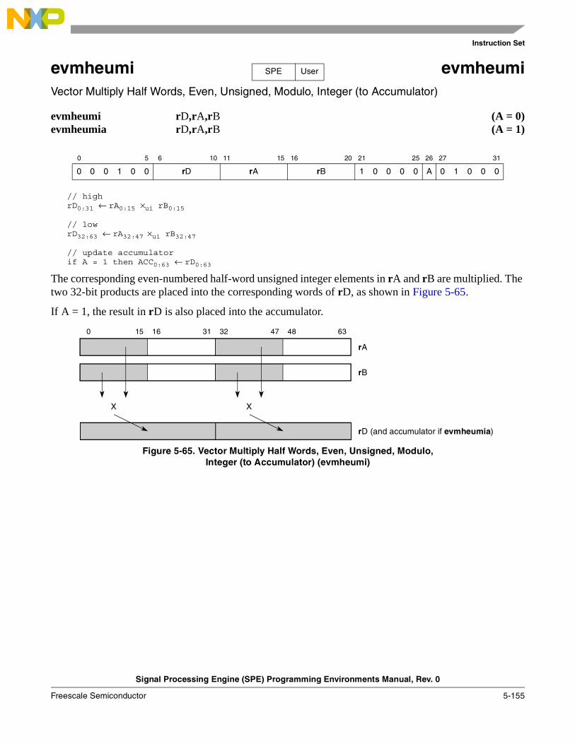
Instruction Set
Signal Processing Engine (SPE) Programming Environments Manual, Rev. 0
Freescale Semiconductor 5-155
evmheumi evmheumiVector Multiply Half Words, Even, Unsigned, Modulo, Integer (to Accumulator)
evmheumi rD,rA,rB (A = 0)evmheumia rD,rA,rB (A = 1)
// highrD0:31 ← rA0:15 ×ui rB0:15
// lowrD32:63 ← rA32:47 ×ui rB32:47
// update accumulatorif A = 1 then ACC0:63 ← rD0:63
The corresponding even-numbered half-word unsigned integer elements in rA and rB are multiplied. The two 32-bit products are placed into the corresponding words of rD, as shown in Figure 5-65.
If A = 1, the result in rD is also placed into the accumulator.
Figure 5-65. Vector Multiply Half Words, Even, Unsigned, Modulo,Integer (to Accumulator) (evmheumi)
0 5 6 10 11 15 16 20 21 25 26 27 31
0 0 0 1 0 0 rD rA rB 1 0 0 0 0 A 0 1 0 0 0
SPE User
15 16 47 480 31 32 63
rA
rB
rD (and accumulator if evmheumia)
XX
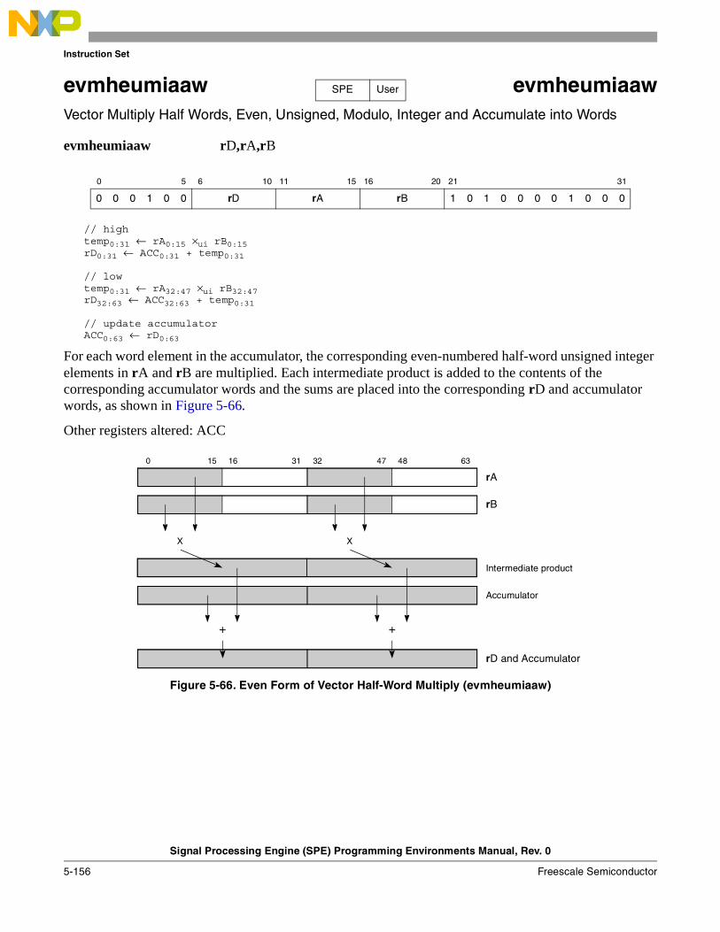
Instruction Set
Signal Processing Engine (SPE) Programming Environments Manual, Rev. 0
5-156 Freescale Semiconductor
evmheumiaaw evmheumiaawVector Multiply Half Words, Even, Unsigned, Modulo, Integer and Accumulate into Words
evmheumiaaw rD,rA,rB
// hightemp0:31 ← rA0:15 ×ui rB0:15rD0:31 ← ACC0:31 + temp0:31
// lowtemp0:31 ← rA32:47 ×ui rB32:47rD32:63 ← ACC32:63 + temp0:31
// update accumulatorACC0:63 ← rD0:63
For each word element in the accumulator, the corresponding even-numbered half-word unsigned integer elements in rA and rB are multiplied. Each intermediate product is added to the contents of the corresponding accumulator words and the sums are placed into the corresponding rD and accumulator words, as shown in Figure 5-66.
Other registers altered: ACC
Figure 5-66. Even Form of Vector Half-Word Multiply (evmheumiaaw)
0 5 6 10 11 15 16 20 21 31
0 0 0 1 0 0 rD rA rB 1 0 1 0 0 0 0 1 0 0 0
SPE User
15 16 47 480 31 32 63
Intermediate product
Accumulator
rB
XX
+ +
rD and Accumulator
rA
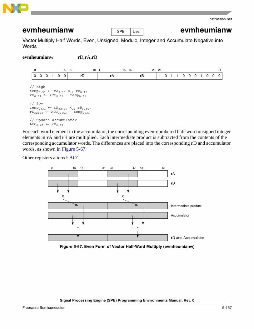
Instruction Set
Signal Processing Engine (SPE) Programming Environments Manual, Rev. 0
Freescale Semiconductor 5-157
evmheumianw evmheumianwVector Multiply Half Words, Even, Unsigned, Modulo, Integer and Accumulate Negative into Words
evmheumianw rD,rA,rB
// hightemp0:31 ← rA0:15 ×ui rB0:15rD0:31 ← ACC0:31 - temp0:31
// lowtemp0:31 ← rA32:47 ×ui rB32:47rD32:63 ← ACC32:63 - temp0:31
// update accumulatorACC0:63 ← rD0:63
For each word element in the accumulator, the corresponding even-numbered half-word unsigned integer elements in rA and rB are multiplied. Each intermediate product is subtracted from the contents of the corresponding accumulator words. The differences are placed into the corresponding rD and accumulator words, as shown in Figure 5-67.
Other registers altered: ACC
Figure 5-67. Even Form of Vector Half-Word Multiply (evmheumianw)
0 5 6 10 11 15 16 20 21 31
0 0 0 1 0 0 rD rA rB 1 0 1 1 0 0 0 1 0 0 0
SPE User
15 16 47 480 31 32 63
Intermediate product
Accumulator
rB
XX
- -
rD and Accumulator
rA
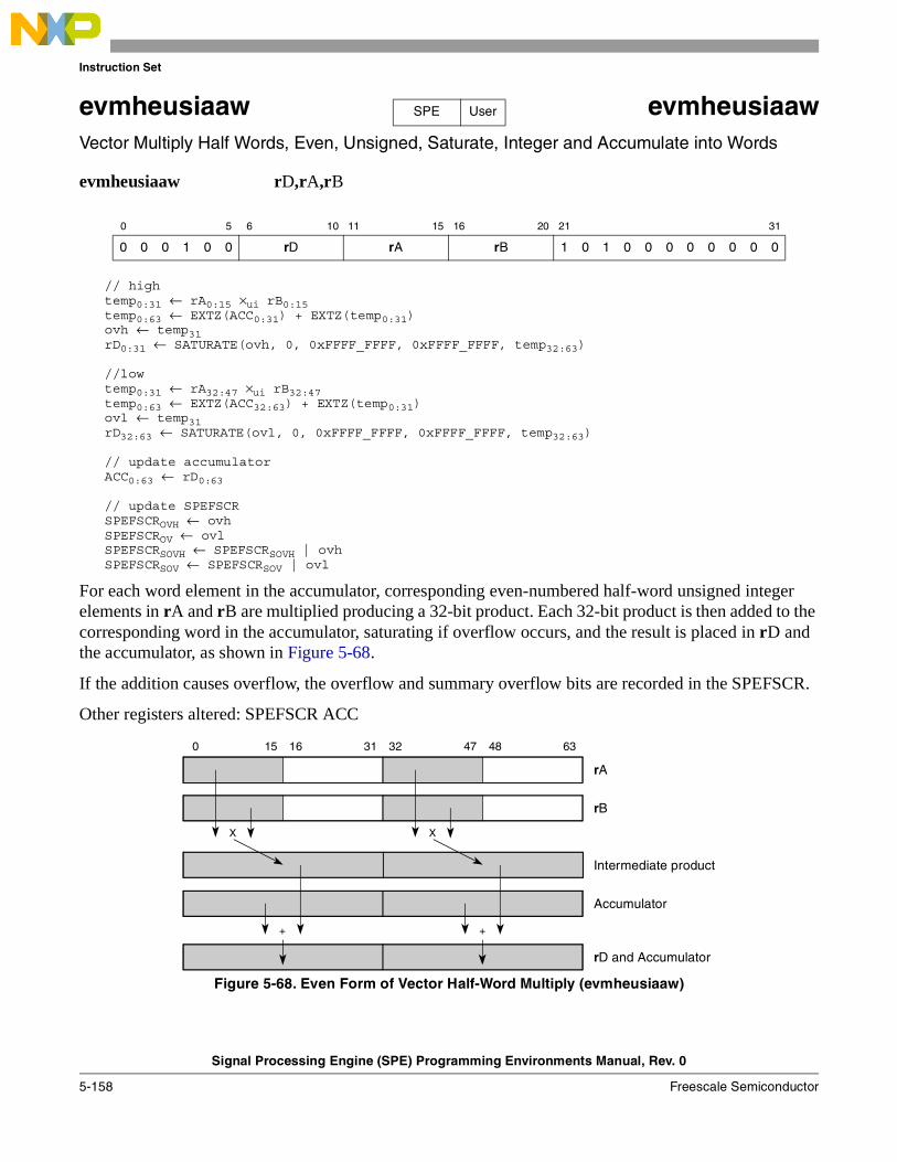
Instruction Set
Signal Processing Engine (SPE) Programming Environments Manual, Rev. 0
5-158 Freescale Semiconductor
evmheusiaaw evmheusiaawVector Multiply Half Words, Even, Unsigned, Saturate, Integer and Accumulate into Words
evmheusiaaw rD,rA,rB
// hightemp0:31 ← rA0:15 ×ui rB0:15 temp0:63 ← EXTZ(ACC0:31) + EXTZ(temp0:31)ovh ← temp31rD0:31 ← SATURATE(ovh, 0, 0xFFFF_FFFF, 0xFFFF_FFFF, temp32:63)
//lowtemp0:31 ← rA32:47 ×ui rB32:47 temp0:63 ← EXTZ(ACC32:63) + EXTZ(temp0:31)ovl ← temp31rD32:63 ← SATURATE(ovl, 0, 0xFFFF_FFFF, 0xFFFF_FFFF, temp32:63)
// update accumulatorACC0:63 ← rD0:63
// update SPEFSCRSPEFSCROVH ← ovhSPEFSCROV ← ovlSPEFSCRSOVH ← SPEFSCRSOVH | ovhSPEFSCRSOV ← SPEFSCRSOV | ovl
For each word element in the accumulator, corresponding even-numbered half-word unsigned integer elements in rA and rB are multiplied producing a 32-bit product. Each 32-bit product is then added to the corresponding word in the accumulator, saturating if overflow occurs, and the result is placed in rD and the accumulator, as shown in Figure 5-68.
If the addition causes overflow, the overflow and summary overflow bits are recorded in the SPEFSCR.
Other registers altered: SPEFSCR ACC
Figure 5-68. Even Form of Vector Half-Word Multiply (evmheusiaaw)
0 5 6 10 11 15 16 20 21 31
0 0 0 1 0 0 rD rA rB 1 0 1 0 0 0 0 0 0 0 0
SPE User
15 16 47 480 31 32 63
Intermediate product
Accumulator
rB
XX
++
rD and Accumulator
rA
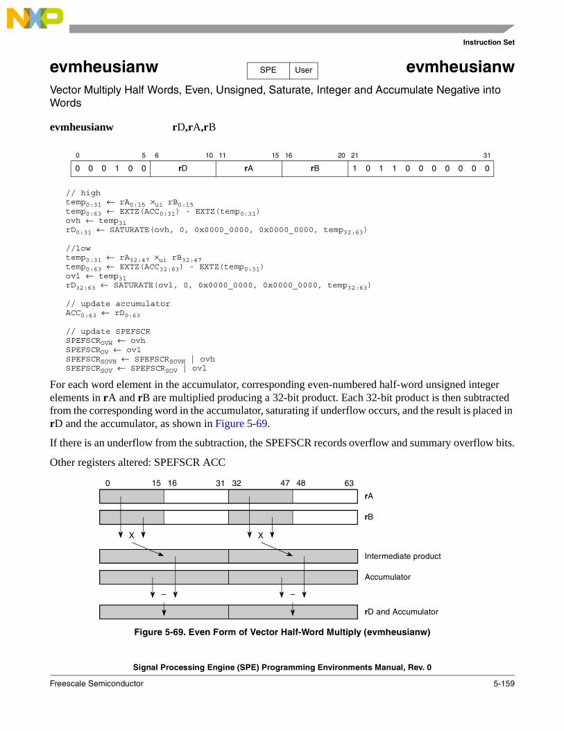
Instruction Set
Signal Processing Engine (SPE) Programming Environments Manual, Rev. 0
Freescale Semiconductor 5-159
evmheusianw evmheusianwVector Multiply Half Words, Even, Unsigned, Saturate, Integer and Accumulate Negative into Words
evmheusianw rD,rA,rB
// hightemp0:31 ← rA0:15 ×ui rB0:15 temp0:63 ← EXTZ(ACC0:31) - EXTZ(temp0:31)ovh ← temp31rD0:31 ← SATURATE(ovh, 0, 0x0000_0000, 0x0000_0000, temp32:63)
//lowtemp0:31 ← rA32:47 ×ui rB32:47 temp0:63 ← EXTZ(ACC32:63) - EXTZ(temp0:31)ovl ← temp31rD32:63 ← SATURATE(ovl, 0, 0x0000_0000, 0x0000_0000, temp32:63)
// update accumulatorACC0:63 ← rD0:63
// update SPEFSCRSPEFSCROVH ← ovhSPEFSCROV ← ovlSPEFSCRSOVH ← SPEFSCRSOVH | ovhSPEFSCRSOV ← SPEFSCRSOV | ovl
For each word element in the accumulator, corresponding even-numbered half-word unsigned integer elements in rA and rB are multiplied producing a 32-bit product. Each 32-bit product is then subtracted from the corresponding word in the accumulator, saturating if underflow occurs, and the result is placed in rD and the accumulator, as shown in Figure 5-69.
If there is an underflow from the subtraction, the SPEFSCR records overflow and summary overflow bits.
Other registers altered: SPEFSCR ACC
Figure 5-69. Even Form of Vector Half-Word Multiply (evmheusianw)
0 5 6 10 11 15 16 20 21 31
0 0 0 1 0 0 rD rA rB 1 0 1 1 0 0 0 0 0 0 0
SPE User
15 16 47 480 31 32 63
Intermediate product
Accumulator
rB
XX
––
rD and Accumulator
rA

Instruction Set
Signal Processing Engine (SPE) Programming Environments Manual, Rev. 0
5-160 Freescale Semiconductor
evmhogsmfaa evmhogsmfaaVector Multiply Half Words, Odd, Guarded, Signed, Modulo, Fractional and Accumulate
evmhogsmfaa rD,rA,rB
temp0:31 ← rA48:63 ×sf rB48:63temp0:63 ← EXTS(temp0:31) rD0:63 ← ACC0:63 + temp0:63
// update accumulatorACC0:63 ← rD0:63
The corresponding low odd-numbered half-word signed fractional elements in rA and rB are multiplied. The intermediate product is sign-extended to 64 bits then added to the contents of the 64-bit accumulator, and the result is placed into rD and into the accumulator, as shown in Figure 5-70.
Note: This is a modulo sum. There is no check for overflow and no saturation is performed. An overflow from the 64-bit sum, if one occurs, is not recorded into the SPEFSCR.
Figure 5-70. evmhogsmfaa (Odd Form)
0 5 6 10 11 15 16 20 21 31
0 0 0 1 0 0 rD rA rB 1 0 1 0 0 1 0 1 1 1 1
SPE User
47 480 31 32 63
Intermediate product
Accumulator
rB
X
+
rD and Accumulator
rA
ssss_ssss_ssss_ssss...ssss
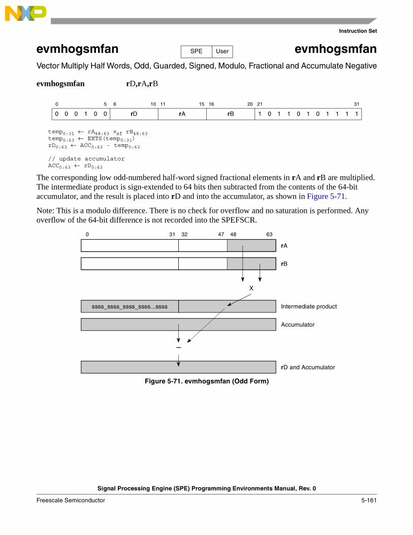
Instruction Set
Signal Processing Engine (SPE) Programming Environments Manual, Rev. 0
Freescale Semiconductor 5-161
evmhogsmfan evmhogsmfanVector Multiply Half Words, Odd, Guarded, Signed, Modulo, Fractional and Accumulate Negative
evmhogsmfan rD,rA,rB
temp0:31 ← rA48:63 ×sf rB48:63temp0:63 ← EXTS(temp0:31)rD0:63 ← ACC0:63 - temp0:63
// update accumulatorACC0:63 ← rD0:63
The corresponding low odd-numbered half-word signed fractional elements in rA and rB are multiplied. The intermediate product is sign-extended to 64 bits then subtracted from the contents of the 64-bit accumulator, and the result is placed into rD and into the accumulator, as shown in Figure 5-71.
Note: This is a modulo difference. There is no check for overflow and no saturation is performed. Any overflow of the 64-bit difference is not recorded into the SPEFSCR.
Figure 5-71. evmhogsmfan (Odd Form)
0 5 6 10 11 15 16 20 21 31
0 0 0 1 0 0 rD rA rB 1 0 1 1 0 1 0 1 1 1 1
SPE User
47 480 31 32 63
Intermediate product
Accumulator
rB
X
–
rD and Accumulator
rA
ssss_ssss_ssss_ssss...ssss

Instruction Set
Signal Processing Engine (SPE) Programming Environments Manual, Rev. 0
5-162 Freescale Semiconductor
evmhogsmiaa evmhogsmiaaVector Multiply Half Words, Odd, Guarded, Signed, Modulo, Integer, and Accumulate
evmhogsmiaa rD,rA,rB
temp0:31 ← rA48:63 ×si rB48:63temp0:63 ← EXTS(temp0:31)rD0:63 ← ACC0:63 + temp0:63
// update accumulatorACC0:63 ← rD0:63
The corresponding low odd-numbered half-word signed integer elements in rA and rB are multiplied. The intermediate product is sign-extended to 64 bits then added to the contents of the 64-bit accumulator, and the result is placed into rD and into the accumulator, as shown in Figure 5-72.
Note: This is a modulo sum. There is no check for overflow and no saturation is performed. An overflow from the 64-bit sum, if one occurs, is not recorded into the SPEFSCR.
Figure 5-72. evmhogsmiaa (Odd Form)
0 5 6 10 11 15 16 20 21 31
0 0 0 1 0 0 rD rA rB 1 0 1 0 0 1 0 1 1 0 1
SPE User
47 480 31 32 63
Intermediate product
Accumulator
rB
X
+
rD and Accumulator
rA
ssss_ssss_ssss_ssss...ssss

Instruction Set
Signal Processing Engine (SPE) Programming Environments Manual, Rev. 0
Freescale Semiconductor 5-163
evmhogsmian evmhogsmianVector Multiply Half Words, Odd, Guarded, Signed, Modulo, Integer and Accumulate Negative
evmhogsmian rD,rA,rB
temp0:31 ← rA48:63 ×si rB48:63temp0:63 ← EXTS(temp0:31)rD0:63 ← ACC0:63 - temp0:63
// update accumulatorACC0:63 ← rD0:63
The corresponding low odd-numbered half-word signed integer elements in rA and rB are multiplied. The intermediate product is sign-extended to 64 bits then subtracted from the contents of the 64-bit accumulator, and the result is placed into rD and into the accumulator, as shown in Figure 5-73.
Note: This is a modulo difference. There is no check for overflow and no saturation is performed. Any overflow of the 64-bit difference is not recorded into the SPEFSCR.
Figure 5-73. evmhogsmian (Odd Form)
0 5 6 10 11 15 16 20 21 31
0 0 0 1 0 0 rD rA rB 1 0 1 1 0 1 0 1 1 0 1
SPE User
47 480 31 32 63
Intermediate product
Accumulator
rB
X
–
rD and Accumulator
rA
ssss_ssss_ssss_ssss...ssss
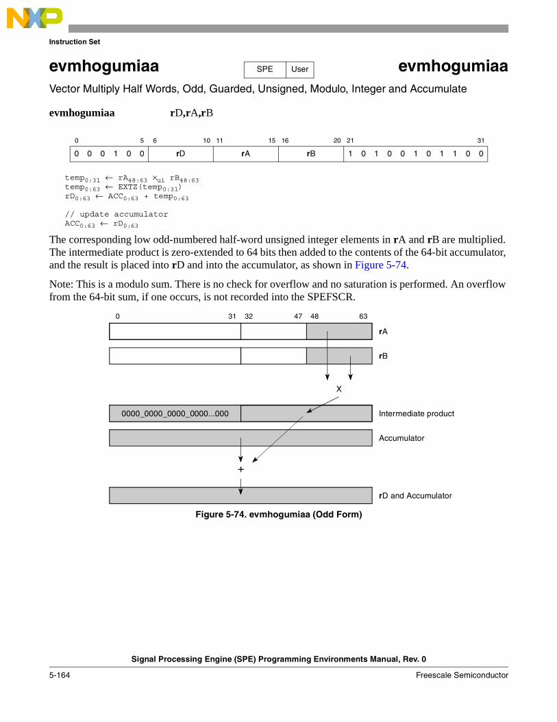
Instruction Set
Signal Processing Engine (SPE) Programming Environments Manual, Rev. 0
5-164 Freescale Semiconductor
evmhogumiaa evmhogumiaaVector Multiply Half Words, Odd, Guarded, Unsigned, Modulo, Integer and Accumulate
evmhogumiaa rD,rA,rB
temp0:31 ← rA48:63 ×ui rB48:63temp0:63 ← EXTZ(temp0:31)rD0:63 ← ACC0:63 + temp0:63
// update accumulatorACC0:63 ← rD0:63
The corresponding low odd-numbered half-word unsigned integer elements in rA and rB are multiplied. The intermediate product is zero-extended to 64 bits then added to the contents of the 64-bit accumulator, and the result is placed into rD and into the accumulator, as shown in Figure 5-74.
Note: This is a modulo sum. There is no check for overflow and no saturation is performed. An overflow from the 64-bit sum, if one occurs, is not recorded into the SPEFSCR.
Figure 5-74. evmhogumiaa (Odd Form)
0 5 6 10 11 15 16 20 21 31
0 0 0 1 0 0 rD rA rB 1 0 1 0 0 1 0 1 1 0 0
SPE User
47 480 31 32 63
Intermediate product
Accumulator
rB
X
+
rD and Accumulator
rA
0000_0000_0000_0000...000
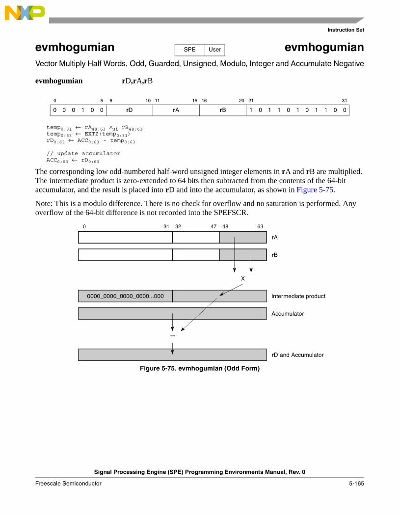
Instruction Set
Signal Processing Engine (SPE) Programming Environments Manual, Rev. 0
Freescale Semiconductor 5-165
evmhogumian evmhogumianVector Multiply Half Words, Odd, Guarded, Unsigned, Modulo, Integer and Accumulate Negative
evmhogumian rD,rA,rB
temp0:31 ← rA48:63 ×ui rB48:63temp0:63 ← EXTZ(temp0:31)rD0:63 ← ACC0:63 - temp0:63
// update accumulatorACC0:63 ← rD0:63
The corresponding low odd-numbered half-word unsigned integer elements in rA and rB are multiplied. The intermediate product is zero-extended to 64 bits then subtracted from the contents of the 64-bit accumulator, and the result is placed into rD and into the accumulator, as shown in Figure 5-75.
Note: This is a modulo difference. There is no check for overflow and no saturation is performed. Any overflow of the 64-bit difference is not recorded into the SPEFSCR.
Figure 5-75. evmhogumian (Odd Form)
0 5 6 10 11 15 16 20 21 31
0 0 0 1 0 0 rD rA rB 1 0 1 1 0 1 0 1 1 0 0
SPE User
47 480 31 32 63
Intermediate product
Accumulator
rB
X
–
rD and Accumulator
rA
0000_0000_0000_0000...000
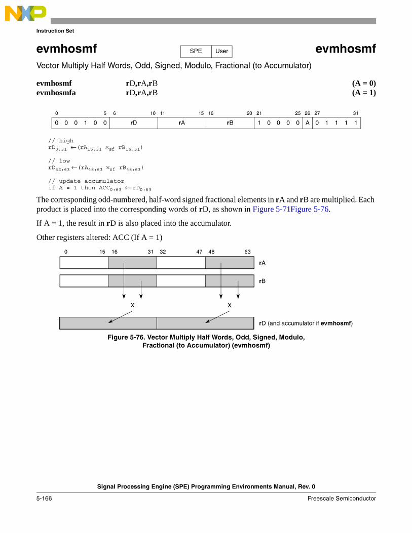
Instruction Set
Signal Processing Engine (SPE) Programming Environments Manual, Rev. 0
5-166 Freescale Semiconductor
evmhosmf evmhosmfVector Multiply Half Words, Odd, Signed, Modulo, Fractional (to Accumulator)
evmhosmf rD,rA,rB (A = 0)evmhosmfa rD,rA,rB (A = 1)
// highrD0:31 ← (rA16:31 ×sf rB16:31)
// lowrD32:63 ← (rA48:63 ×sf rB48:63)
// update accumulatorif A = 1 then ACC0:63 ← rD0:63
The corresponding odd-numbered, half-word signed fractional elements in rA and rB are multiplied. Each product is placed into the corresponding words of rD, as shown in Figure 5-71Figure 5-76.
If A = 1, the result in rD is also placed into the accumulator.
Other registers altered: ACC (If A = 1)
Figure 5-76. Vector Multiply Half Words, Odd, Signed, Modulo,Fractional (to Accumulator) (evmhosmf)
0 5 6 10 11 15 16 20 21 25 26 27 31
0 0 0 1 0 0 rD rA rB 1 0 0 0 0 A 0 1 1 1 1
SPE User
15 16 47 480 31 32 63
rA
rB
rD (and accumulator if evmhosmf)
X X

Instruction Set
Signal Processing Engine (SPE) Programming Environments Manual, Rev. 0
Freescale Semiconductor 5-167
evmhosmfaaw evmhosmfaawVector Multiply Half Words, Odd, Signed, Modulo, Fractional and Accumulate into Words
evmhosmfaaw rD,rA,rB
// hightemp0:31 ← rA16:31 ×sf rB16:31 rD0:31 ← ACC0:31 + temp0:31
// lowtemp0:31 ← rA48:63 ×sf rB48:63 rD32:63 ← ACC32:63 + temp0:31
// update accumulatorACC0:63 ← rD0:63
For each word element in the accumulator, the corresponding odd-numbered half-word signed fractional elements in rA and rB are multiplied. The 32 bits of each intermediate product is added to the contents of the corresponding accumulator word and the results are placed into the corresponding rD words and into the accumulator, as shown in Figure 5-77.
Other registers altered: ACC
Figure 5-77. Odd Form of Vector Half-Word Multiply (evmhosmfaaw)
0 5 6 10 11 15 16 20 21 31
0 0 0 1 0 0 rD rA rB 1 0 1 0 0 0 0 1 1 1 1
SPE User
15 16 47 480 31 32 63
Intermediate product
Accumulator
rB
X X
+ +
rD and Accumulator
rA
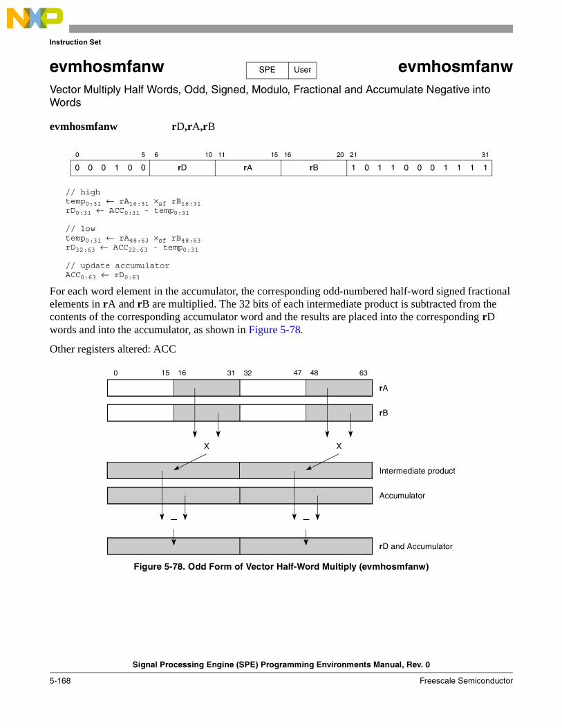
Instruction Set
Signal Processing Engine (SPE) Programming Environments Manual, Rev. 0
5-168 Freescale Semiconductor
evmhosmfanw evmhosmfanwVector Multiply Half Words, Odd, Signed, Modulo, Fractional and Accumulate Negative into Words
evmhosmfanw rD,rA,rB
// hightemp0:31 ← rA16:31 ×sf rB16:31 rD0:31 ← ACC0:31 - temp0:31
// lowtemp0:31 ← rA48:63 ×sf rB48:63 rD32:63 ← ACC32:63 - temp0:31
// update accumulatorACC0:63 ← rD0:63
For each word element in the accumulator, the corresponding odd-numbered half-word signed fractional elements in rA and rB are multiplied. The 32 bits of each intermediate product is subtracted from the contents of the corresponding accumulator word and the results are placed into the corresponding rD words and into the accumulator, as shown in Figure 5-78.
Other registers altered: ACC
Figure 5-78. Odd Form of Vector Half-Word Multiply (evmhosmfanw)
0 5 6 10 11 15 16 20 21 31
0 0 0 1 0 0 rD rA rB 1 0 1 1 0 0 0 1 1 1 1
SPE User
15 16 47 480 31 32 63
Intermediate product
Accumulator
rB
X X
– –
rD and Accumulator
rA
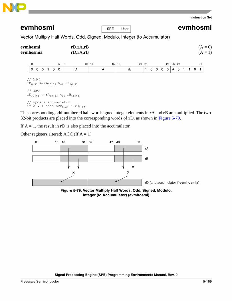
Instruction Set
Signal Processing Engine (SPE) Programming Environments Manual, Rev. 0
Freescale Semiconductor 5-169
evmhosmi evmhosmiVector Multiply Half Words, Odd, Signed, Modulo, Integer (to Accumulator)
evmhosmi rD,rA,rB (A = 0)evmhosmia rD,rA,rB (A = 1)
// highrD0:31 ← rA16:31 ×si rB16:31
// lowrD32:63 ← rA48:63 ×si rB48:63
// update accumulatorif A = 1 then ACC0:63 ← rD0:63
The corresponding odd-numbered half-word signed integer elements in rA and rB are multiplied. The two 32-bit products are placed into the corresponding words of rD, as shown in Figure 5-79.
If A = 1, the result in rD is also placed into the accumulator.
Other registers altered: ACC (If A = 1)
Figure 5-79. Vector Multiply Half Words, Odd, Signed, Modulo,Integer (to Accumulator) (evmhosmi)
0 5 6 10 11 15 16 20 21 25 26 27 31
0 0 0 1 0 0 rD rA rB 1 0 0 0 0 A 0 1 1 0 1
SPE User
15 16 47 480 31 32 63
rA
rB
rD (and accumulator if evmhosmia)
X X
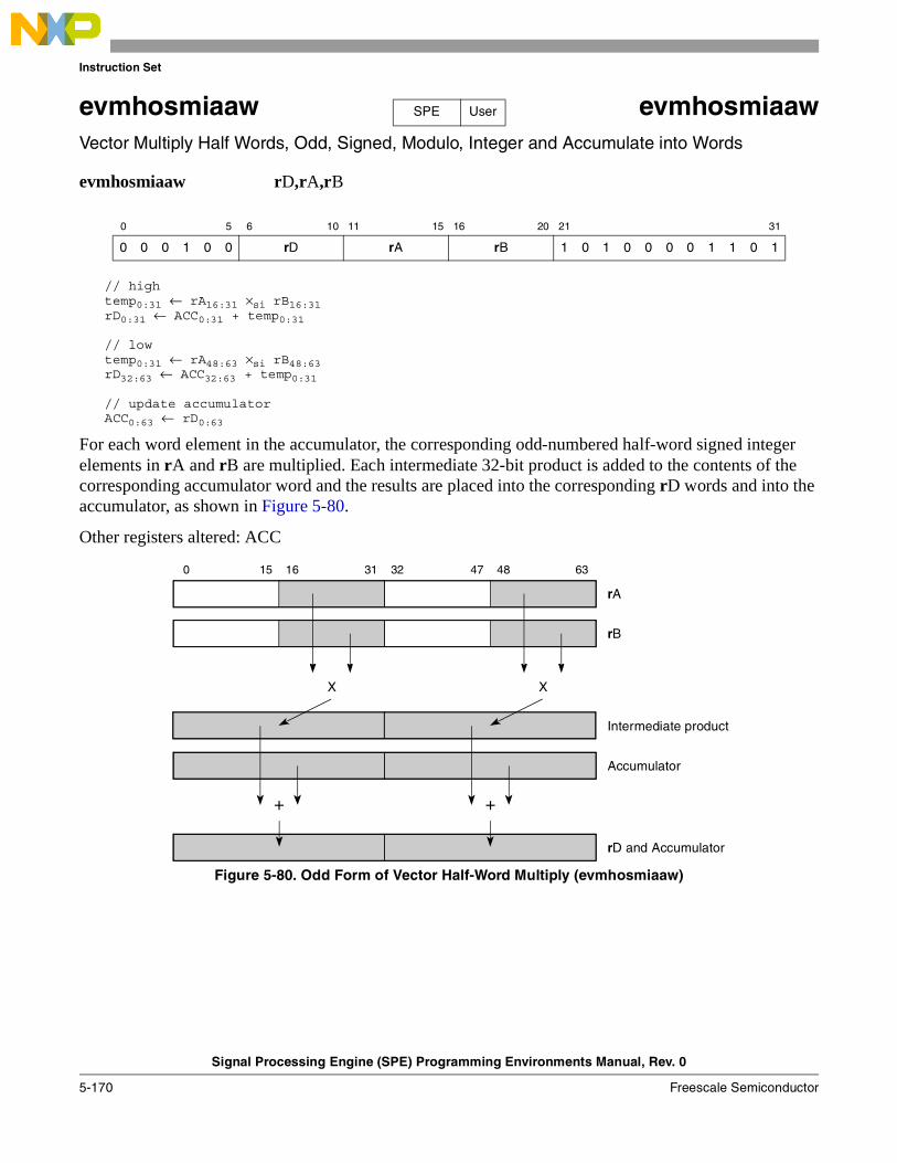
Instruction Set
Signal Processing Engine (SPE) Programming Environments Manual, Rev. 0
5-170 Freescale Semiconductor
evmhosmiaaw evmhosmiaawVector Multiply Half Words, Odd, Signed, Modulo, Integer and Accumulate into Words
evmhosmiaaw rD,rA,rB
// hightemp0:31 ← rA16:31 ×si rB16:31 rD0:31 ← ACC0:31 + temp0:31
// lowtemp0:31 ← rA48:63 ×si rB48:63 rD32:63 ← ACC32:63 + temp0:31
// update accumulatorACC0:63 ← rD0:63
For each word element in the accumulator, the corresponding odd-numbered half-word signed integer elements in rA and rB are multiplied. Each intermediate 32-bit product is added to the contents of the corresponding accumulator word and the results are placed into the corresponding rD words and into the accumulator, as shown in Figure 5-80.
Other registers altered: ACC
Figure 5-80. Odd Form of Vector Half-Word Multiply (evmhosmiaaw)
0 5 6 10 11 15 16 20 21 31
0 0 0 1 0 0 rD rA rB 1 0 1 0 0 0 0 1 1 0 1
SPE User
15 16 47 480 31 32 63
Intermediate product
Accumulator
rB
X X
+ +
rD and Accumulator
rA
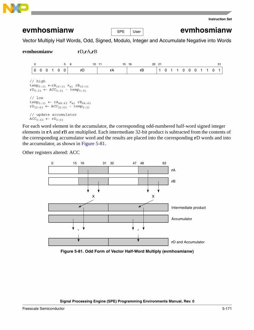
Instruction Set
Signal Processing Engine (SPE) Programming Environments Manual, Rev. 0
Freescale Semiconductor 5-171
evmhosmianw evmhosmianwVector Multiply Half Words, Odd, Signed, Modulo, Integer and Accumulate Negative into Words
evmhosmianw rD,rA,rB
// hightemp0:31 ←rA16:31 ×si rB16:31 rD0:31 ← ACC0:31 - temp0:31
// lowtemp0:31 ← rA48:63 ×si rB48:63 rD32:63 ← ACC32:63 - temp0:31
// update accumulatorACC0:63 ← rD0:63
For each word element in the accumulator, the corresponding odd-numbered half-word signed integer elements in rA and rB are multiplied. Each intermediate 32-bit product is subtracted from the contents of the corresponding accumulator word and the results are placed into the corresponding rD words and into the accumulator, as shown in Figure 5-81.
Other registers altered: ACC
Figure 5-81. Odd Form of Vector Half-Word Multiply (evmhosmianw)
0 5 6 10 11 15 16 20 21 31
0 0 0 1 0 0 rD rA rB 1 0 1 1 0 0 0 1 1 0 1
SPE User
15 16 47 480 31 32 63
Intermediate product
Accumulator
rB
X X
--
rD and Accumulator
rA
Instruction Set
Signal Processing Engine (SPE) Programming Environments Manual, Rev. 0
5-172 Freescale Semiconductor
evmhossf evmhossfVector Multiply Half Words, Odd, Signed, Saturate, Fractional (to Accumulator)
evmhossf rD,rA,rB (A = 0)evmhossfa rD,rA,rB (A = 1)
// hightemp0:31 ← rA16:31 ×sf rB16:31 if (rA16:31 = 0x8000) & (rB16:31 = 0x8000) then
rD0:31 ← 0x7FFF_FFFF //saturate movh ← 1
elserD0:31 ← temp0:31movh ← 0
// lowtemp0:31 ← rA48:63 ×sf rB48:63 if (rA48:63 = 0x8000) & (rB48:63 = 0x8000) then
rD32:63 ← 0x7FFF_FFFF //saturatemovl ← 1
elserD32:63 ← temp0:31movl ← 0
// update accumulatorif A = 1 then ACC0:63 ← rD0:63
// update SPEFSCRSPEFSCROVH ← movhSPEFSCROV ← movlSPEFSCRSOVH ← SPEFSCRSOVH | movhSPEFSCRSOV ← SPEFSCRSOV | movl
The corresponding odd-numbered half-word signed fractional elements in rA and rB are multiplied. The 32 bits of each product are placed into the corresponding words of rD, as shown in Figure 5-82. If both inputs are –1.0, the result saturates to the largest positive signed fraction and the overflow and summary overflow bits are recorded in the SPEFSCR.
If A = 1, the result in rD is also placed into the accumulator.
Other registers altered: SPEFSCR ACC (If A = 1)
0 5 6 10 11 15 16 20 21 25 26 27 31
0 0 0 1 0 0 rD rA rB 1 0 0 0 0 A 0 0 1 1 1
SPE User
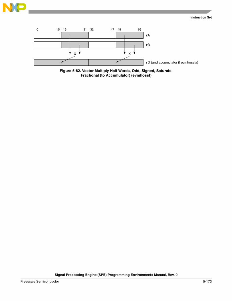
Instruction Set
Signal Processing Engine (SPE) Programming Environments Manual, Rev. 0
Freescale Semiconductor 5-173
Figure 5-82. Vector Multiply Half Words, Odd, Signed, Saturate,Fractional (to Accumulator) (evmhossf)
15 16 47 480 31 32 63
rA
rB
rD (and accumulator if evmhossfa)
X X
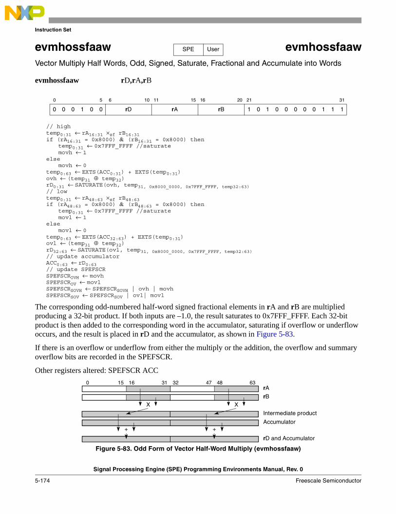
Instruction Set
Signal Processing Engine (SPE) Programming Environments Manual, Rev. 0
5-174 Freescale Semiconductor
evmhossfaaw evmhossfaawVector Multiply Half Words, Odd, Signed, Saturate, Fractional and Accumulate into Words
evmhossfaaw rD,rA,rB
// hightemp0:31 ← rA16:31 ×sf rB16:31 if (rA16:31 = 0x8000) & (rB16:31 = 0x8000) then
temp0:31 ← 0x7FFF_FFFF //saturate movh ← 1
elsemovh ← 0
temp0:63 ← EXTS(ACC0:31) + EXTS(temp0:31)ovh ← (temp31 ⊕ temp32)rD0:31 ← SATURATE(ovh, temp31, 0x8000_0000, 0x7FFF_FFFF, temp32:63) // lowtemp0:31 ← rA48:63 ×sf rB48:63 if (rA48:63 = 0x8000) & (rB48:63 = 0x8000) then
temp0:31 ← 0x7FFF_FFFF //saturate movl ← 1
elsemovl ← 0
temp0:63 ← EXTS(ACC32:63) + EXTS(temp0:31)ovl ← (temp31 ⊕ temp32)rD32:63 ← SATURATE(ovl, temp31, 0x8000_0000, 0x7FFF_FFFF, temp32:63) // update accumulatorACC0:63 ← rD0:63// update SPEFSCRSPEFSCROVH ← movhSPEFSCROV ← movlSPEFSCRSOVH ← SPEFSCRSOVH | ovh | movhSPEFSCRSOV ← SPEFSCRSOV | ovl| movl
The corresponding odd-numbered half-word signed fractional elements in rA and rB are multiplied producing a 32-bit product. If both inputs are –1.0, the result saturates to 0x7FFF_FFFF. Each 32-bit product is then added to the corresponding word in the accumulator, saturating if overflow or underflow occurs, and the result is placed in rD and the accumulator, as shown in Figure 5-83.
If there is an overflow or underflow from either the multiply or the addition, the overflow and summary overflow bits are recorded in the SPEFSCR.
Other registers altered: SPEFSCR ACC
Figure 5-83. Odd Form of Vector Half-Word Multiply (evmhossfaaw)
0 5 6 10 11 15 16 20 21 31
0 0 0 1 0 0 rD rA rB 1 0 1 0 0 0 0 0 1 1 1
SPE User
15 16 47 480 31 32 63
Intermediate product
Accumulator
rBX X
+ +
rD and Accumulator
rA
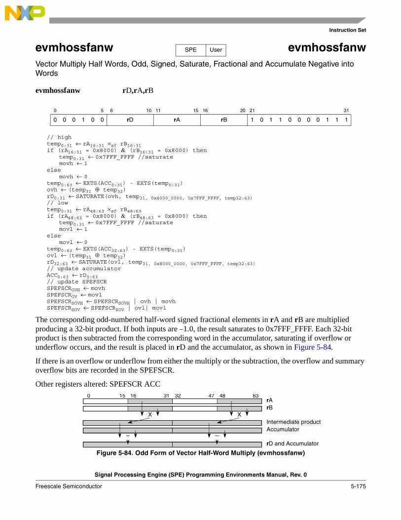
Instruction Set
Signal Processing Engine (SPE) Programming Environments Manual, Rev. 0
Freescale Semiconductor 5-175
evmhossfanw evmhossfanwVector Multiply Half Words, Odd, Signed, Saturate, Fractional and Accumulate Negative into Words
evmhossfanw rD,rA,rB
// hightemp0:31 ← rA16:31 ×sf rB16:31 if (rA16:31 = 0x8000) & (rB16:31 = 0x8000) then
temp0:31 ← 0x7FFF_FFFF //saturate movh ← 1
elsemovh ← 0
temp0:63 ← EXTS(ACC0:31) - EXTS(temp0:31)ovh ← (temp31 ⊕ temp32)rD0:31 ← SATURATE(ovh, temp31, 0x8000_0000, 0x7FFF_FFFF, temp32:63) // lowtemp0:31 ← rA48:63 ×sf rB48:63 if (rA48:63 = 0x8000) & (rB48:63 = 0x8000) then
temp0:31 ← 0x7FFF_FFFF //saturate movl ← 1
elsemovl ← 0
temp0:63 ← EXTS(ACC32:63) - EXTS(temp0:31)ovl ← (temp31 ⊕ temp32)rD32:63 ← SATURATE(ovl, temp31, 0x8000_0000, 0x7FFF_FFFF, temp32:63) // update accumulatorACC0:63 ← rD0:63// update SPEFSCRSPEFSCROVH ← movhSPEFSCROV ← movlSPEFSCRSOVH ← SPEFSCRSOVH | ovh | movhSPEFSCRSOV ← SPEFSCRSOV | ovl| movl
The corresponding odd-numbered half-word signed fractional elements in rA and rB are multiplied producing a 32-bit product. If both inputs are –1.0, the result saturates to 0x7FFF_FFFF. Each 32-bit product is then subtracted from the corresponding word in the accumulator, saturating if overflow or underflow occurs, and the result is placed in rD and the accumulator, as shown in Figure 5-84.
If there is an overflow or underflow from either the multiply or the subtraction, the overflow and summary overflow bits are recorded in the SPEFSCR.
Other registers altered: SPEFSCR ACC
Figure 5-84. Odd Form of Vector Half-Word Multiply (evmhossfanw)
0 5 6 10 11 15 16 20 21 31
0 0 0 1 0 0 rD rA rB 1 0 1 1 0 0 0 0 1 1 1
SPE User
15 16 47 480 31 32 63
Intermediate productAccumulator
rBX X
– --rD and Accumulator
rA
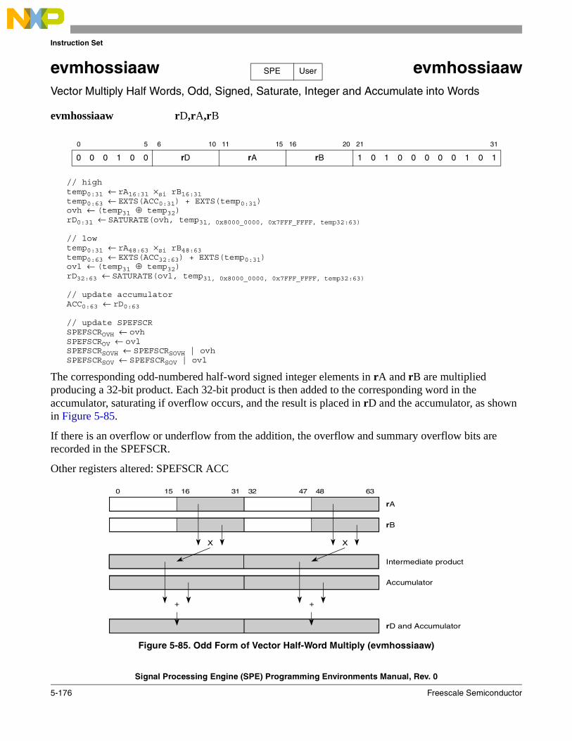
Instruction Set
Signal Processing Engine (SPE) Programming Environments Manual, Rev. 0
5-176 Freescale Semiconductor
evmhossiaaw evmhossiaawVector Multiply Half Words, Odd, Signed, Saturate, Integer and Accumulate into Words
evmhossiaaw rD,rA,rB
// hightemp0:31 ← rA16:31 ×si rB16:31 temp0:63 ← EXTS(ACC0:31) + EXTS(temp0:31)ovh ← (temp31 ⊕ temp32)rD0:31 ← SATURATE(ovh, temp31, 0x8000_0000, 0x7FFF_FFFF, temp32:63)
// lowtemp0:31 ← rA48:63 ×si rB48:63temp0:63 ← EXTS(ACC32:63) + EXTS(temp0:31)ovl ← (temp31 ⊕ temp32)rD32:63 ← SATURATE(ovl, temp31, 0x8000_0000, 0x7FFF_FFFF, temp32:63)
// update accumulatorACC0:63 ← rD0:63
// update SPEFSCRSPEFSCROVH ← ovhSPEFSCROV ← ovlSPEFSCRSOVH ← SPEFSCRSOVH | ovhSPEFSCRSOV ← SPEFSCRSOV | ovl
The corresponding odd-numbered half-word signed integer elements in rA and rB are multiplied producing a 32-bit product. Each 32-bit product is then added to the corresponding word in the accumulator, saturating if overflow occurs, and the result is placed in rD and the accumulator, as shown in Figure 5-85.
If there is an overflow or underflow from the addition, the overflow and summary overflow bits are recorded in the SPEFSCR.
Other registers altered: SPEFSCR ACC
Figure 5-85. Odd Form of Vector Half-Word Multiply (evmhossiaaw)
0 5 6 10 11 15 16 20 21 31
0 0 0 1 0 0 rD rA rB 1 0 1 0 0 0 0 0 1 0 1
SPE User
15 16 47 480 31 32 63
Intermediate product
Accumulator
rB
X X
+ +
rD and Accumulator
rA
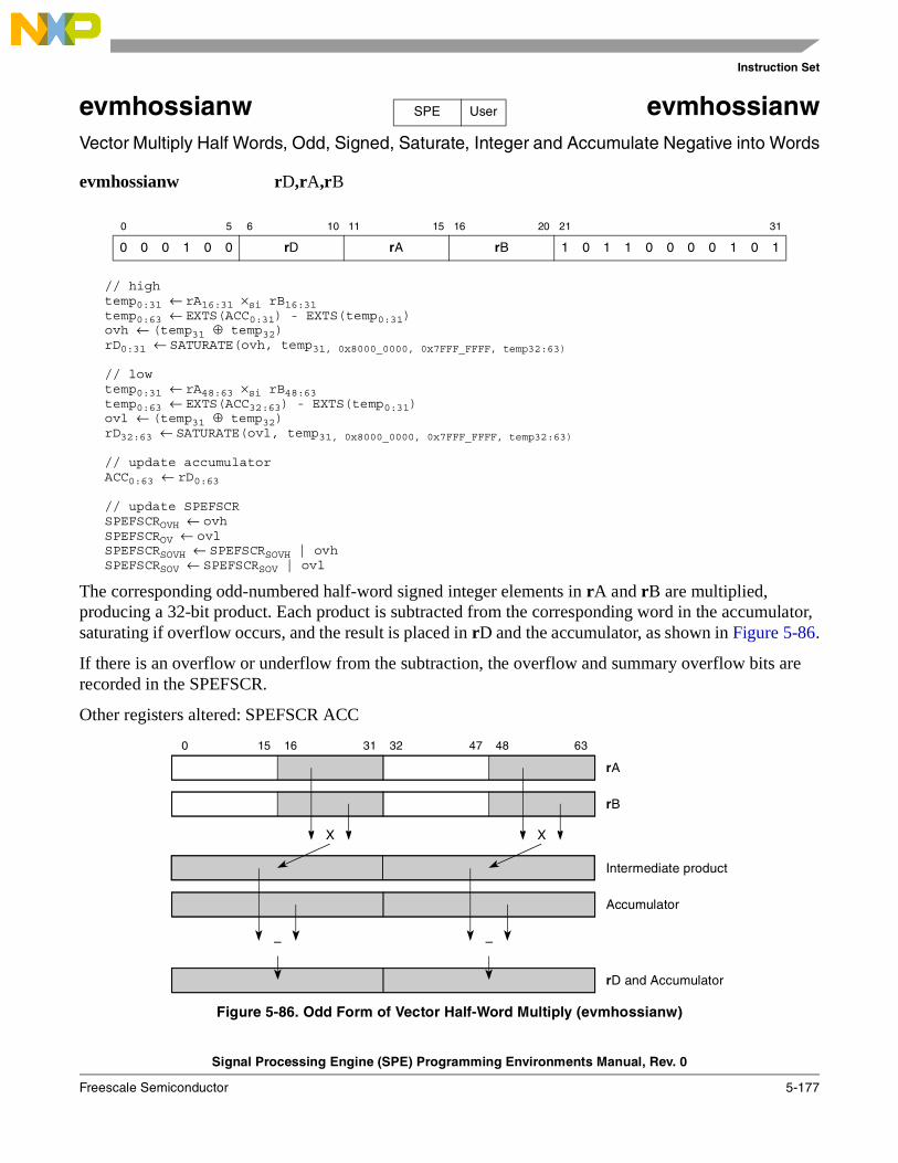
Instruction Set
Signal Processing Engine (SPE) Programming Environments Manual, Rev. 0
Freescale Semiconductor 5-177
evmhossianw evmhossianwVector Multiply Half Words, Odd, Signed, Saturate, Integer and Accumulate Negative into Words
evmhossianw rD,rA,rB
// hightemp0:31 ← rA16:31 ×si rB16:31 temp0:63 ← EXTS(ACC0:31) - EXTS(temp0:31)ovh ← (temp31 ⊕ temp32)rD0:31 ← SATURATE(ovh, temp31, 0x8000_0000, 0x7FFF_FFFF, temp32:63)
// lowtemp0:31 ← rA48:63 ×si rB48:63temp0:63 ← EXTS(ACC32:63) - EXTS(temp0:31)ovl ← (temp31 ⊕ temp32)rD32:63 ← SATURATE(ovl, temp31, 0x8000_0000, 0x7FFF_FFFF, temp32:63)
// update accumulatorACC0:63 ← rD0:63
// update SPEFSCRSPEFSCROVH ← ovhSPEFSCROV ← ovlSPEFSCRSOVH ← SPEFSCRSOVH | ovhSPEFSCRSOV ← SPEFSCRSOV | ovl
The corresponding odd-numbered half-word signed integer elements in rA and rB are multiplied, producing a 32-bit product. Each product is subtracted from the corresponding word in the accumulator, saturating if overflow occurs, and the result is placed in rD and the accumulator, as shown in Figure 5-86.
If there is an overflow or underflow from the subtraction, the overflow and summary overflow bits are recorded in the SPEFSCR.
Other registers altered: SPEFSCR ACC
Figure 5-86. Odd Form of Vector Half-Word Multiply (evmhossianw)
0 5 6 10 11 15 16 20 21 31
0 0 0 1 0 0 rD rA rB 1 0 1 1 0 0 0 0 1 0 1
SPE User
15 16 47 480 31 32 63
Intermediate product
Accumulator
rB
X X
– –
rD and Accumulator
rA
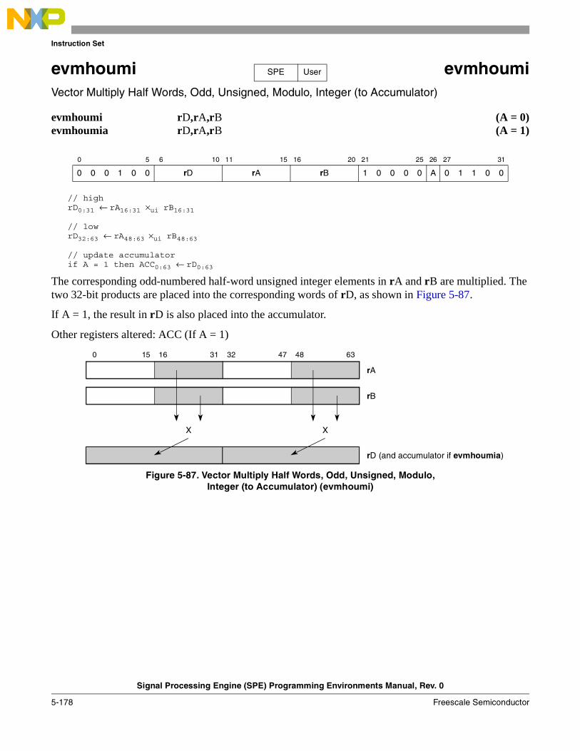
Instruction Set
Signal Processing Engine (SPE) Programming Environments Manual, Rev. 0
5-178 Freescale Semiconductor
evmhoumi evmhoumiVector Multiply Half Words, Odd, Unsigned, Modulo, Integer (to Accumulator)
evmhoumi rD,rA,rB (A = 0)evmhoumia rD,rA,rB (A = 1)
// highrD0:31 ← rA16:31 ×ui rB16:31
// lowrD32:63 ← rA48:63 ×ui rB48:63
// update accumulatorif A = 1 then ACC0:63 ← rD0:63
The corresponding odd-numbered half-word unsigned integer elements in rA and rB are multiplied. The two 32-bit products are placed into the corresponding words of rD, as shown in Figure 5-87.
If A = 1, the result in rD is also placed into the accumulator.
Other registers altered: ACC (If A = 1)
Figure 5-87. Vector Multiply Half Words, Odd, Unsigned, Modulo,Integer (to Accumulator) (evmhoumi)
0 5 6 10 11 15 16 20 21 25 26 27 31
0 0 0 1 0 0 rD rA rB 1 0 0 0 0 A 0 1 1 0 0
SPE User
15 16 47 480 31 32 63
rA
rB
rD (and accumulator if evmhoumia)
X X
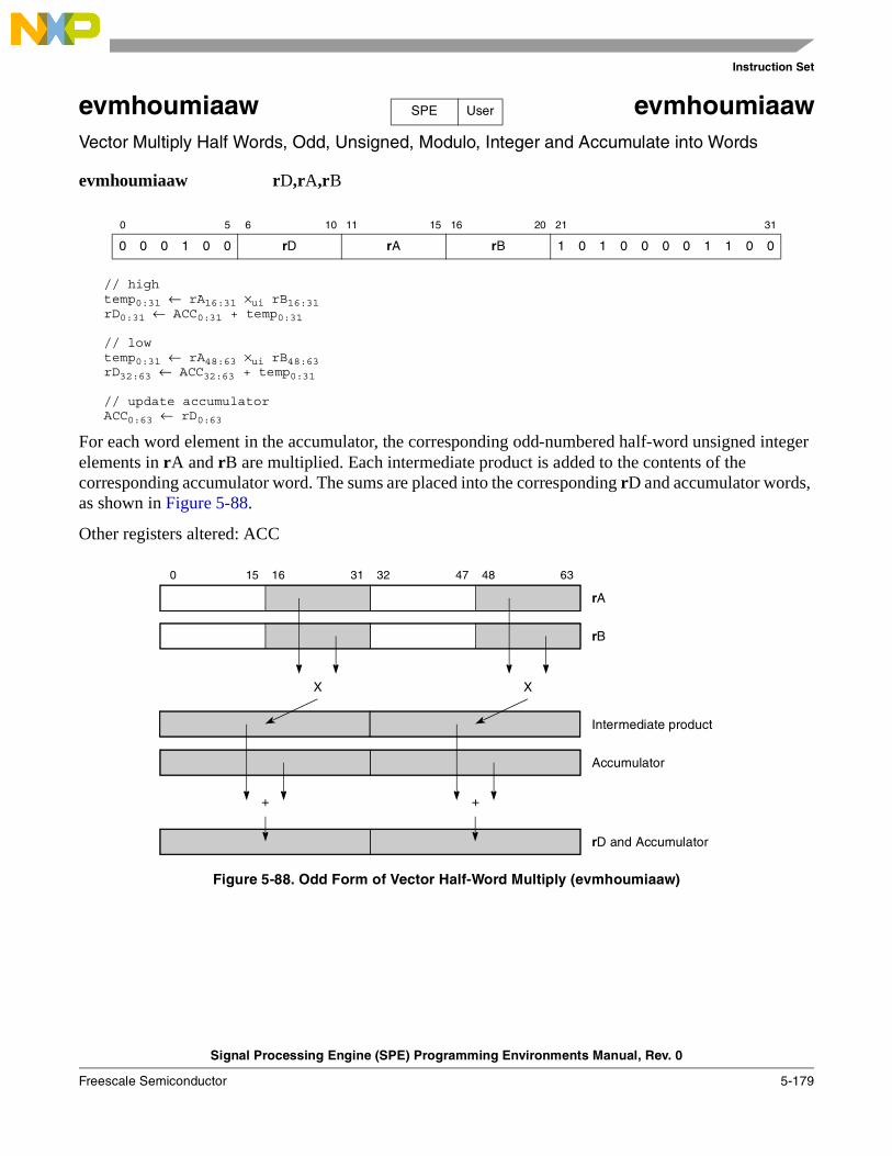
Instruction Set
Signal Processing Engine (SPE) Programming Environments Manual, Rev. 0
Freescale Semiconductor 5-179
evmhoumiaaw evmhoumiaawVector Multiply Half Words, Odd, Unsigned, Modulo, Integer and Accumulate into Words
evmhoumiaaw rD,rA,rB
// hightemp0:31 ← rA16:31 ×ui rB16:31rD0:31 ← ACC0:31 + temp0:31
// lowtemp0:31 ← rA48:63 ×ui rB48:63rD32:63 ← ACC32:63 + temp0:31
// update accumulatorACC0:63 ← rD0:63
For each word element in the accumulator, the corresponding odd-numbered half-word unsigned integer elements in rA and rB are multiplied. Each intermediate product is added to the contents of the corresponding accumulator word. The sums are placed into the corresponding rD and accumulator words, as shown in Figure 5-88.
Other registers altered: ACC
Figure 5-88. Odd Form of Vector Half-Word Multiply (evmhoumiaaw)
0 5 6 10 11 15 16 20 21 31
0 0 0 1 0 0 rD rA rB 1 0 1 0 0 0 0 1 1 0 0
SPE User
15 16 47 480 31 32 63
Intermediate product
Accumulator
rB
X X
+ +
rD and Accumulator
rA
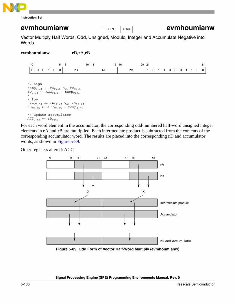
Instruction Set
Signal Processing Engine (SPE) Programming Environments Manual, Rev. 0
5-180 Freescale Semiconductor
evmhoumianw evmhoumianwVector Multiply Half Words, Odd, Unsigned, Modulo, Integer and Accumulate Negative into Words
evmhoumianw rD,rA,rB
// hightemp0:31 ← rA0:15 ×ui rB0:15rD0:31 ← ACC0:31 - temp0:31// lowtemp0:31 ← rA32:47 ×ui rB32:47rD32:63 ← ACC32:63 - temp0:31
// update accumulatorACC0:63 ← rD0:63
For each word element in the accumulator, the corresponding odd-numbered half-word unsigned integer elements in rA and rB are multiplied. Each intermediate product is subtracted from the contents of the corresponding accumulator word. The results are placed into the corresponding rD and accumulator words, as shown in Figure 5-89.
Other registers altered: ACC
Figure 5-89. Odd Form of Vector Half-Word Multiply (evmhoumianw)
0 5 6 10 11 15 16 20 21 31
0 0 0 1 0 0 rD rA rB 1 0 1 1 0 0 0 1 1 0 0
SPE User
15 16 47 480 31 32 63
Intermediate product
Accumulator
rB
X X
––
rD and Accumulator
rA
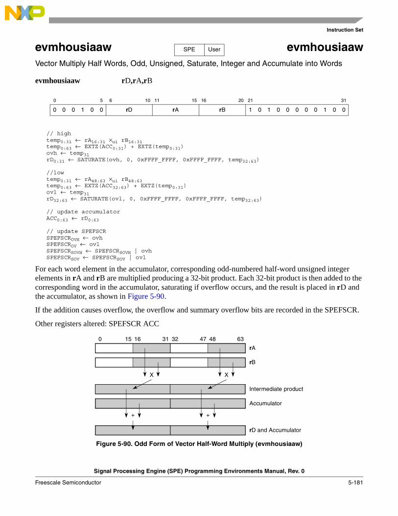
Instruction Set
Signal Processing Engine (SPE) Programming Environments Manual, Rev. 0
Freescale Semiconductor 5-181
evmhousiaaw evmhousiaawVector Multiply Half Words, Odd, Unsigned, Saturate, Integer and Accumulate into Words
evmhousiaaw rD,rA,rB
// hightemp0:31 ← rA16:31 ×ui rB16:31 temp0:63 ← EXTZ(ACC0:31) + EXTZ(temp0:31)ovh ← temp31rD0:31 ← SATURATE(ovh, 0, 0xFFFF_FFFF, 0xFFFF_FFFF, temp32:63)
//lowtemp0:31 ← rA48:63 ×ui rB48:63 temp0:63 ← EXTZ(ACC32:63) + EXTZ(temp0:31)ovl ← temp31rD32:63 ← SATURATE(ovl, 0, 0xFFFF_FFFF, 0xFFFF_FFFF, temp32:63)
// update accumulatorACC0:63 ← rD0:63
// update SPEFSCRSPEFSCROVH ← ovhSPEFSCROV ← ovlSPEFSCRSOVH ← SPEFSCRSOVH | ovhSPEFSCRSOV ← SPEFSCRSOV | ovl
For each word element in the accumulator, corresponding odd-numbered half-word unsigned integer elements in rA and rB are multiplied producing a 32-bit product. Each 32-bit product is then added to the corresponding word in the accumulator, saturating if overflow occurs, and the result is placed in rD and the accumulator, as shown in Figure 5-90.
If the addition causes overflow, the overflow and summary overflow bits are recorded in the SPEFSCR.
Other registers altered: SPEFSCR ACC
Figure 5-90. Odd Form of Vector Half-Word Multiply (evmhousiaaw)
0 5 6 10 11 15 16 20 21 31
0 0 0 1 0 0 rD rA rB 1 0 1 0 0 0 0 0 1 0 0
SPE User
15 16 47 480 31 32 63
Intermediate product
Accumulator
rB
X X
+ +
rD and Accumulator
rA
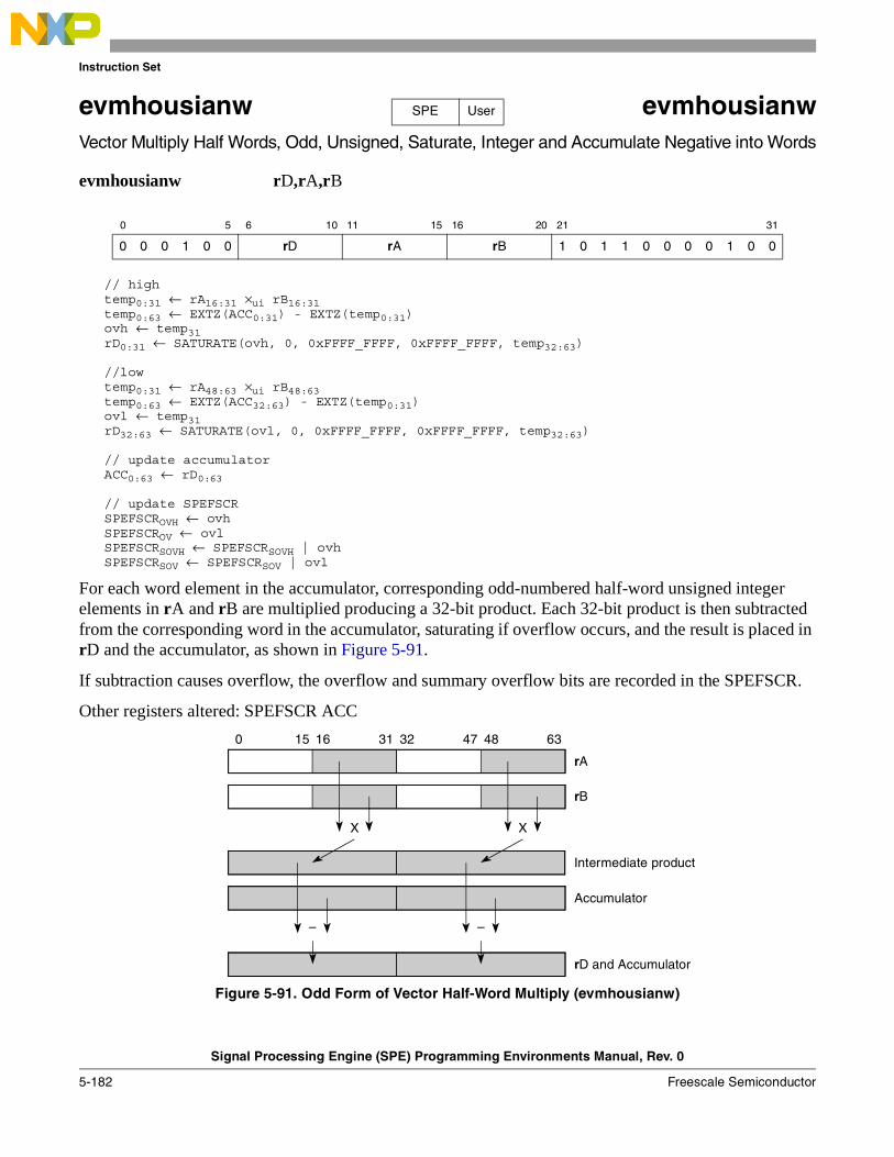
Instruction Set
Signal Processing Engine (SPE) Programming Environments Manual, Rev. 0
5-182 Freescale Semiconductor
evmhousianw evmhousianwVector Multiply Half Words, Odd, Unsigned, Saturate, Integer and Accumulate Negative into Words
evmhousianw rD,rA,rB
// hightemp0:31 ← rA16:31 ×ui rB16:31 temp0:63 ← EXTZ(ACC0:31) - EXTZ(temp0:31)ovh ← temp31rD0:31 ← SATURATE(ovh, 0, 0xFFFF_FFFF, 0xFFFF_FFFF, temp32:63)
//lowtemp0:31 ← rA48:63 ×ui rB48:63 temp0:63 ← EXTZ(ACC32:63) - EXTZ(temp0:31)ovl ← temp31rD32:63 ← SATURATE(ovl, 0, 0xFFFF_FFFF, 0xFFFF_FFFF, temp32:63)
// update accumulatorACC0:63 ← rD0:63
// update SPEFSCRSPEFSCROVH ← ovhSPEFSCROV ← ovlSPEFSCRSOVH ← SPEFSCRSOVH | ovhSPEFSCRSOV ← SPEFSCRSOV | ovl
For each word element in the accumulator, corresponding odd-numbered half-word unsigned integer elements in rA and rB are multiplied producing a 32-bit product. Each 32-bit product is then subtracted from the corresponding word in the accumulator, saturating if overflow occurs, and the result is placed in rD and the accumulator, as shown in Figure 5-91.
If subtraction causes overflow, the overflow and summary overflow bits are recorded in the SPEFSCR.
Other registers altered: SPEFSCR ACC
Figure 5-91. Odd Form of Vector Half-Word Multiply (evmhousianw)
0 5 6 10 11 15 16 20 21 31
0 0 0 1 0 0 rD rA rB 1 0 1 1 0 0 0 0 1 0 0
SPE User
15 16 47 480 31 32 63
Intermediate product
Accumulator
rB
X X
– –
rD and Accumulator
rA
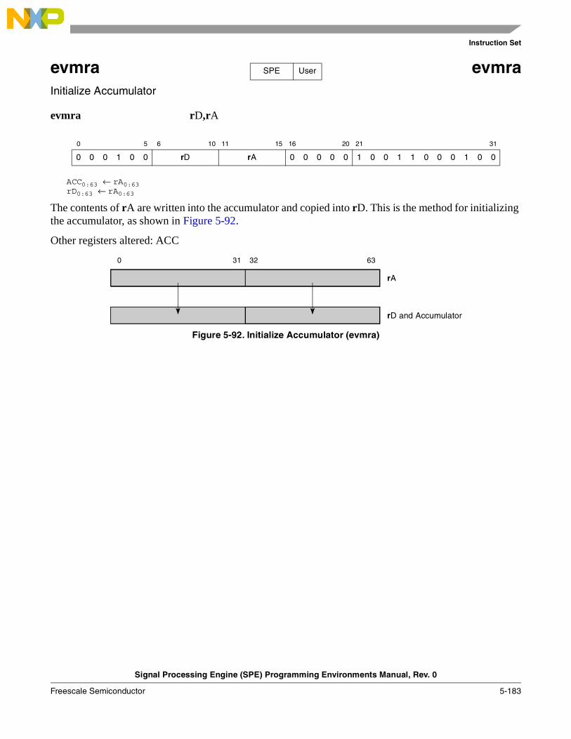
Instruction Set
Signal Processing Engine (SPE) Programming Environments Manual, Rev. 0
Freescale Semiconductor 5-183
evmra evmraInitialize Accumulator
evmra rD,rA
ACC0:63 ← rA0:63rD0:63 ← rA0:63
The contents of rA are written into the accumulator and copied into rD. This is the method for initializing the accumulator, as shown in Figure 5-92.
Other registers altered: ACC
Figure 5-92. Initialize Accumulator (evmra)
0 5 6 10 11 15 16 20 21 31
0 0 0 1 0 0 rD rA 0 0 0 0 0 1 0 0 1 1 0 0 0 1 0 0
SPE User
0 31 32 63
rA
rD and Accumulator
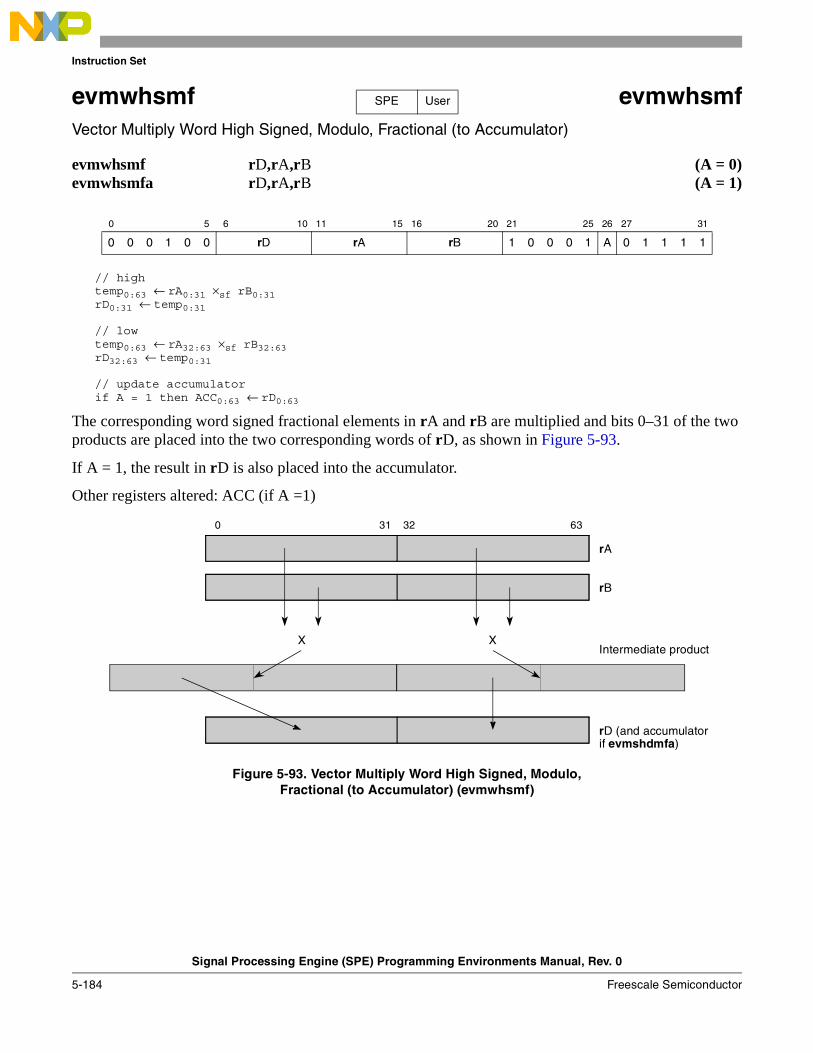
Instruction Set
Signal Processing Engine (SPE) Programming Environments Manual, Rev. 0
5-184 Freescale Semiconductor
evmwhsmf evmwhsmfVector Multiply Word High Signed, Modulo, Fractional (to Accumulator)
evmwhsmf rD,rA,rB (A = 0)evmwhsmfa rD,rA,rB (A = 1)
// hightemp0:63 ← rA0:31 ×sf rB0:31 rD0:31 ← temp0:31
// lowtemp0:63 ← rA32:63 ×sf rB32:63rD32:63 ← temp0:31
// update accumulatorif A = 1 then ACC0:63 ← rD0:63
The corresponding word signed fractional elements in rA and rB are multiplied and bits 0–31 of the two products are placed into the two corresponding words of rD, as shown in Figure 5-93.
If A = 1, the result in rD is also placed into the accumulator.
Other registers altered: ACC (if A =1)
Figure 5-93. Vector Multiply Word High Signed, Modulo,Fractional (to Accumulator) (evmwhsmf)
0 5 6 10 11 15 16 20 21 25 26 27 31
0 0 0 1 0 0 rD rA rB 1 0 0 0 1 A 0 1 1 1 1
SPE User
0 31 32 63
Intermediate product
rB
X
rD (and accumulator
rA
X
if evmshdmfa)
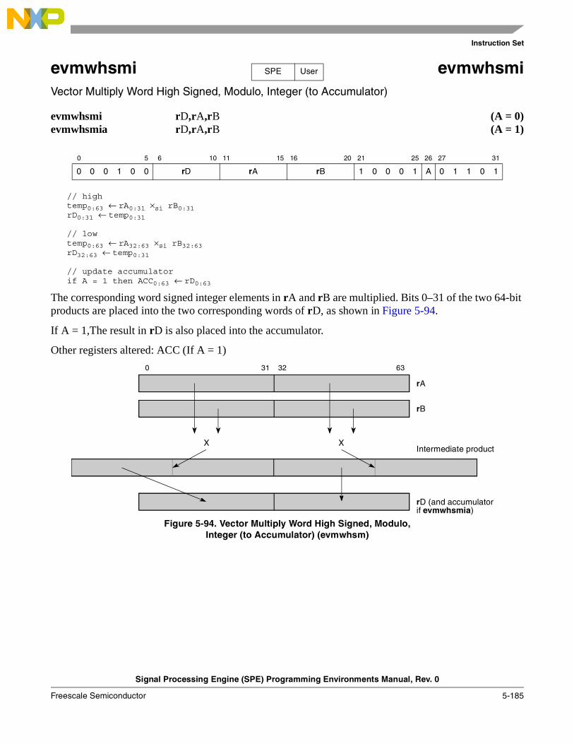
Instruction Set
Signal Processing Engine (SPE) Programming Environments Manual, Rev. 0
Freescale Semiconductor 5-185
evmwhsmi evmwhsmiVector Multiply Word High Signed, Modulo, Integer (to Accumulator)
evmwhsmi rD,rA,rB (A = 0)evmwhsmia rD,rA,rB (A = 1)
// hightemp0:63 ← rA0:31 ×si rB0:31rD0:31 ← temp0:31
// lowtemp0:63 ← rA32:63 ×si rB32:63rD32:63 ← temp0:31
// update accumulatorif A = 1 then ACC0:63 ← rD0:63
The corresponding word signed integer elements in rA and rB are multiplied. Bits 0–31 of the two 64-bit products are placed into the two corresponding words of rD, as shown in Figure 5-94.
If A = 1,The result in rD is also placed into the accumulator.
Other registers altered: ACC (If A = 1)
Figure 5-94. Vector Multiply Word High Signed, Modulo,Integer (to Accumulator) (evmwhsm)
0 5 6 10 11 15 16 20 21 25 26 27 31
0 0 0 1 0 0 rD rA rB 1 0 0 0 1 A 0 1 1 0 1
SPE User
0 31 32 63
Intermediate product
rB
X
rD (and accumulator
rA
X
if evmwhsmia)
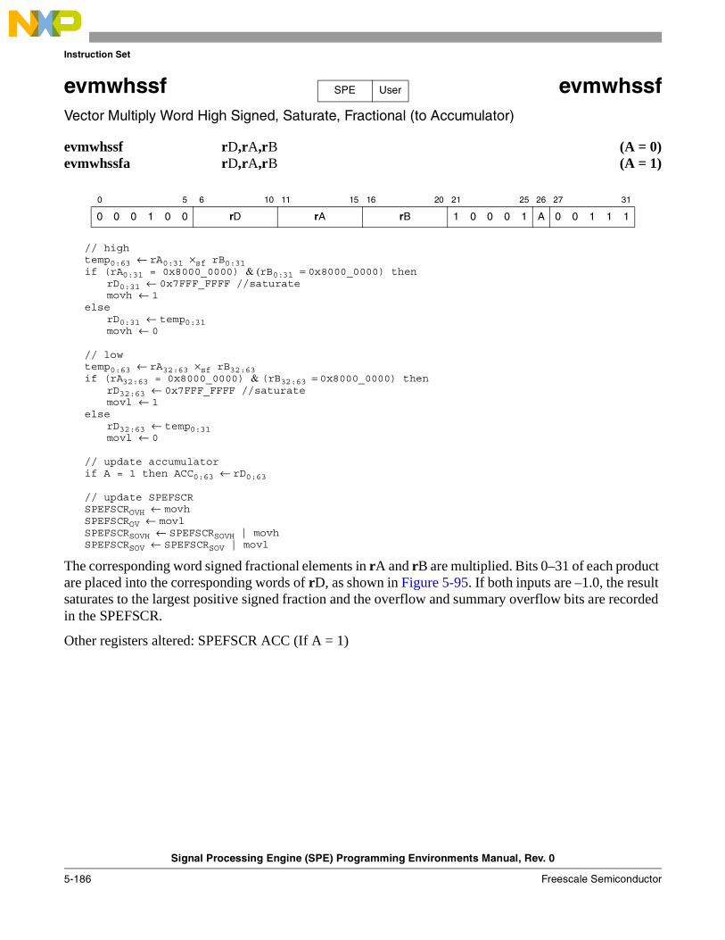
Instruction Set
Signal Processing Engine (SPE) Programming Environments Manual, Rev. 0
5-186 Freescale Semiconductor
evmwhssf evmwhssfVector Multiply Word High Signed, Saturate, Fractional (to Accumulator)
evmwhssf rD,rA,rB (A = 0)evmwhssfa rD,rA,rB (A = 1)
// hightemp0:63 ← rA0:31 ×sf rB0:31 if (rA0:31 = 0x8000_0000) & (rB0:31 = 0x8000_0000) then
rD0:31 ← 0x7FFF_FFFF //saturate movh ← 1
elserD0:31 ← temp0:31movh ← 0
// lowtemp0:63 ← rA32:63 ×sf rB32:63 if (rA32:63 = 0x8000_0000) & (rB32:63 = 0x8000_0000) then
rD32:63 ← 0x7FFF_FFFF //saturatemovl ← 1
elserD32:63 ← temp0:31movl ← 0
// update accumulatorif A = 1 then ACC0:63 ← rD0:63
// update SPEFSCRSPEFSCROVH ← movhSPEFSCROV ← movlSPEFSCRSOVH ← SPEFSCRSOVH | movhSPEFSCRSOV ← SPEFSCRSOV | movl
The corresponding word signed fractional elements in rA and rB are multiplied. Bits 0–31 of each product are placed into the corresponding words of rD, as shown in Figure 5-95. If both inputs are –1.0, the result saturates to the largest positive signed fraction and the overflow and summary overflow bits are recorded in the SPEFSCR.
Other registers altered: SPEFSCR ACC (If A = 1)
0 5 6 10 11 15 16 20 21 25 26 27 31
0 0 0 1 0 0 rD rA rB 1 0 0 0 1 A 0 0 1 1 1
SPE User
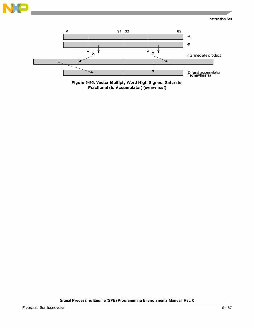
Instruction Set
Signal Processing Engine (SPE) Programming Environments Manual, Rev. 0
Freescale Semiconductor 5-187
Figure 5-95. Vector Multiply Word High Signed, Saturate,Fractional (to Accumulator) (evmwhssf)
0 31 32 63
Intermediate product
rB
X
rD (and accumulator
rA
X
if evmwhssfa)
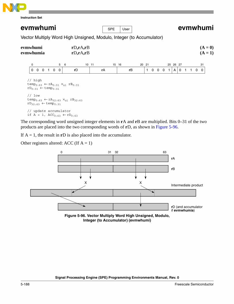
Instruction Set
Signal Processing Engine (SPE) Programming Environments Manual, Rev. 0
5-188 Freescale Semiconductor
evmwhumi evmwhumiVector Multiply Word High Unsigned, Modulo, Integer (to Accumulator)
evmwhumi rD,rA,rB (A = 0)evmwhumia rD,rA,rB (A = 1)
// hightemp0:63 ← rA0:31 ×ui rB0:31rD0:31 ← temp0:31
// lowtemp0:63 ← rA32:63 ×ui rB32:63rD32:63 ← temp0:31
// update accumulatorif A = 1, ACC0:63 ← rD0:63
The corresponding word unsigned integer elements in rA and rB are multiplied. Bits 0–31 of the two products are placed into the two corresponding words of rD, as shown in Figure 5-96.
If A = 1, the result in rD is also placed into the accumulator.
Other registers altered: ACC (If A = 1)
Figure 5-96. Vector Multiply Word High Unsigned, Modulo,Integer (to Accumulator) (evmwhumi)
0 5 6 10 11 15 16 20 21 25 26 27 31
0 0 0 1 0 0 rD rA rB 1 0 0 0 1 A 0 1 1 0 0
SPE User
0 31 32 63
Intermediate product
rB
X
rD (and accumulator
rA
X
if evmwhumia)
Instruction Set
Signal Processing Engine (SPE) Programming Environments Manual, Rev. 0
Freescale Semiconductor 5-189
evmwlsmiaaw evmwlsmiaawVector Multiply Word Low Signed, Modulo, Integer and Accumulate in Words
evmwlsmiaaw rD,rA,rB
// hightemp0:63 ← rA0:31 ×si rB0:31rD0:31 ← ACC0:31 + temp32:63
// lowtemp0:63 ← rA32:63 ×si rB32:63rD32:63 ← ACC32:63 + temp32:63
// update accumulatorACC0:63 ← rD0:63
For each word element in the accumulator, the corresponding word signed integer elements in rA and rB are multiplied. The least significant 32 bits of each intermediate product is added to the contents of the corresponding accumulator words, and the result is placed into rD and the accumulator, as shown in Figure 5-97.
NOTECare should be taken if the intermediate product cannot be represented in 32 bits as some implementations produce an undefined final result. Status bits are set that indicate that such an overflow occurred.
Other registers altered: ACC
Figure 5-97. Vector Multiply Word Low Signed, Modulo, Integer andAccumulate in Words (evmwlsmiaaw)
0 5 6 10 11 15 16 20 21 31
0 0 0 1 0 0 rD rA rB 1 0 1 0 1 0 0 1 0 0 1
SPE User
0 31 32 63
Intermediate product
rB
X
Accumulator
rA
X
++
rD and Accumulator
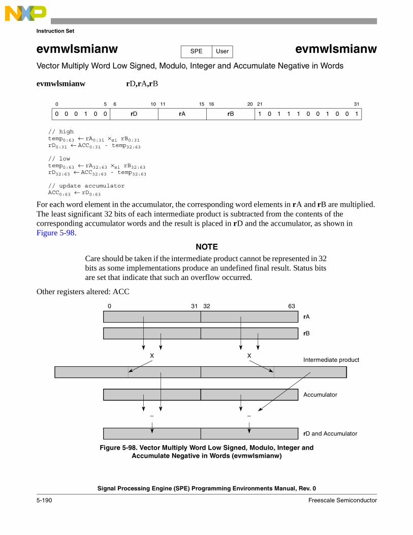
Instruction Set
Signal Processing Engine (SPE) Programming Environments Manual, Rev. 0
5-190 Freescale Semiconductor
evmwlsmianw evmwlsmianwVector Multiply Word Low Signed, Modulo, Integer and Accumulate Negative in Words
evmwlsmianw rD,rA,rB
// hightemp0:63 ← rA0:31 ×si rB0:31rD0:31 ← ACC0:31 - temp32:63
// lowtemp0:63 ← rA32:63 ×si rB32:63rD32:63 ← ACC32:63 - temp32:63
// update accumulatorACC0:63 ← rD0:63
For each word element in the accumulator, the corresponding word elements in rA and rB are multiplied. The least significant 32 bits of each intermediate product is subtracted from the contents of the corresponding accumulator words and the result is placed in rD and the accumulator, as shown in Figure 5-98.
NOTECare should be taken if the intermediate product cannot be represented in 32 bits as some implementations produce an undefined final result. Status bits are set that indicate that such an overflow occurred.
Other registers altered: ACC
Figure 5-98. Vector Multiply Word Low Signed, Modulo, Integer andAccumulate Negative in Words (evmwlsmianw)
0 5 6 10 11 15 16 20 21 31
0 0 0 1 0 0 rD rA rB 1 0 1 1 1 0 0 1 0 0 1
SPE User
0 31 32 63
Intermediate product
rB
X
Accumulator
rA
X
––
rD and Accumulator
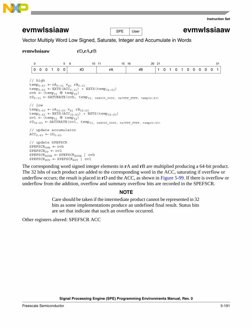
Instruction Set
Signal Processing Engine (SPE) Programming Environments Manual, Rev. 0
Freescale Semiconductor 5-191
evmwlssiaaw evmwlssiaawVector Multiply Word Low Signed, Saturate, Integer and Accumulate in Words
evmwlssiaaw rD,rA,rB
// hightemp0:63 ← rA0:31 ×si rB0:31 temp0:63 ← EXTS(ACC0:31) + EXTS(temp32:63)ovh ← (temp31 ⊕ temp32)rD0:31 ← SATURATE(ovh, temp31, 0x8000_0000, 0x7FFF_FFFF, temp32:63)
// lowtemp0:63 ← rA32:63 ×si rB32:63 temp0:63 ← EXTS(ACC32:63) + EXTS(temp32:63)ovl ← (temp31 ⊕ temp32)rD32:63 ← SATURATE(ovl, temp31, 0x8000_0000, 0x7FFF_FFFF, temp32:63)
// update accumulatorACC0:63 ← rD0:63
// update SPEFSCRSPEFSCROVH ← ovhSPEFSCROV ← ovlSPEFSCRSOVH ← SPEFSCRSOVH | ovhSPEFSCRSOV ← SPEFSCRSOV | ovl
The corresponding word signed integer elements in rA and rB are multiplied producing a 64-bit product. The 32 lsbs of each product are added to the corresponding word in the ACC, saturating if overflow or underflow occurs; the result is placed in rD and the ACC, as shown in Figure 5-99. If there is overflow or underflow from the addition, overflow and summary overflow bits are recorded in the SPEFSCR.
NOTECare should be taken if the intermediate product cannot be represented in 32 bits as some implementations produce an undefined final result. Status bits are set that indicate that such an overflow occurred.
Other registers altered: SPEFSCR ACC
0 5 6 10 11 15 16 20 21 31
0 0 0 1 0 0 rD rA rB 1 0 1 0 1 0 0 0 0 0 1
SPE User
Instruction Set
Signal Processing Engine (SPE) Programming Environments Manual, Rev. 0
5-192 Freescale Semiconductor
Figure 5-99. Vector Multiply Word Low Signed, Saturate, Integer andAccumulate in Words (evmwlssiaaw)
0 31 32 63
Intermediate product
rB
X
Accumulator
rA
X
++
rD and Accumulator
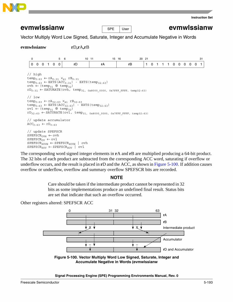
Instruction Set
Signal Processing Engine (SPE) Programming Environments Manual, Rev. 0
Freescale Semiconductor 5-193
evmwlssianw evmwlssianwVector Multiply Word Low Signed, Saturate, Integer and Accumulate Negative in Words
evmwlssianw rD,rA,rB
// hightemp0:63 ← rA0:31 ×si rB0:31 temp0:63 ← EXTS(ACC0:31) - EXTS(temp32:63)ovh ← (temp31 ⊕ temp32)rD0:31 ← SATURATE(ovh, temp31, 0x8000_0000, 0x7FFF_FFFF, temp32:63)
// lowtemp0:63 ← rA32:63 ×si rB32:63 temp0:63 ← EXTS(ACC32:63) - EXTS(temp32:63)ovl ← (temp31 ⊕ temp32)rD32:63 ← SATURATE(ovl, temp31, 0x8000_0000, 0x7FFF_FFFF, temp32:63)
// update accumulatorACC0:63 ← rD0:63
// update SPEFSCRSPEFSCROVH ← ovhSPEFSCROV ← ovlSPEFSCRSOVH ← SPEFSCRSOVH | ovhSPEFSCRSOV ← SPEFSCRSOV | ovl
The corresponding word signed integer elements in rA and rB are multiplied producing a 64-bit product. The 32 lsbs of each product are subtracted from the corresponding ACC word, saturating if overflow or underflow occurs, and the result is placed in rD and the ACC, as shown in Figure 5-100. If addition causes overflow or underflow, overflow and summary overflow SPEFSCR bits are recorded.
NOTECare should be taken if the intermediate product cannot be represented in 32 bits as some implementations produce an undefined final result. Status bits are set that indicate that such an overflow occurred.
Other registers altered: SPEFSCR ACC
Figure 5-100. Vector Multiply Word Low Signed, Saturate, Integer andAccumulate Negative in Words (evmwlssianw
0 5 6 10 11 15 16 20 21 31
0 0 0 1 0 0 rD rA rB 1 0 1 1 1 0 0 0 0 0 1
SPE User
0 31 32 63
Intermediate product
rB
X
Accumulator
rA
X
––rD and Accumulator
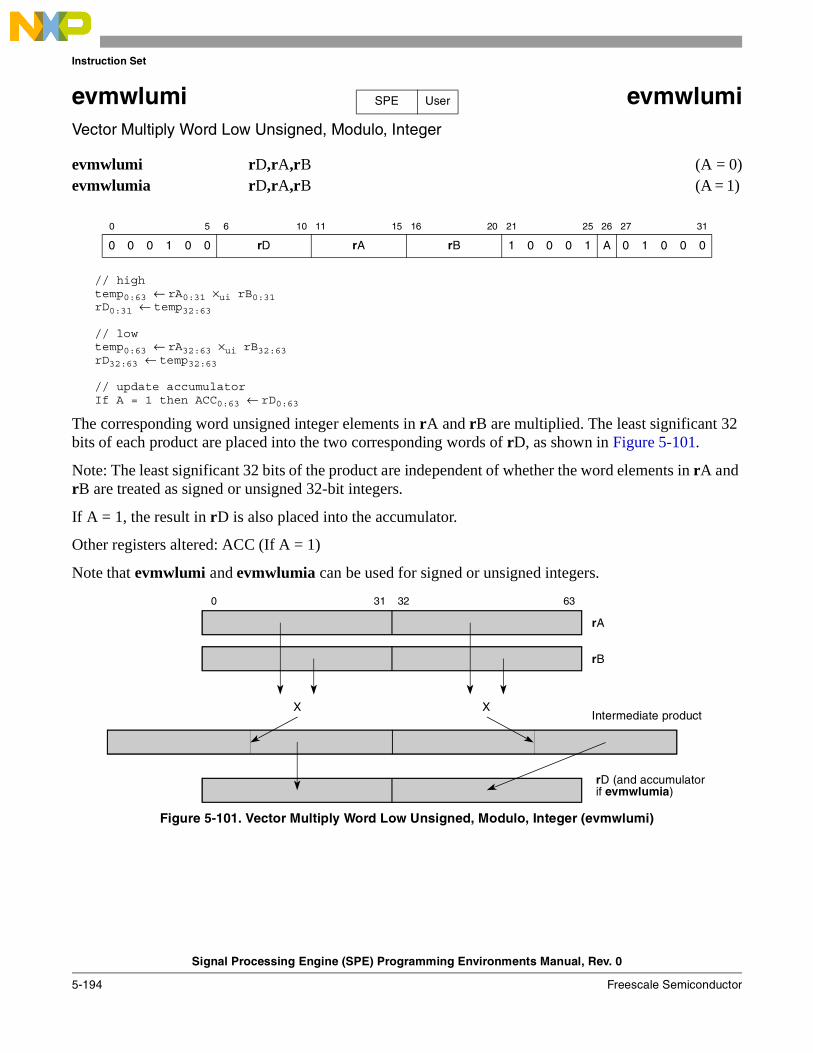
Instruction Set
Signal Processing Engine (SPE) Programming Environments Manual, Rev. 0
5-194 Freescale Semiconductor
evmwlumi evmwlumiVector Multiply Word Low Unsigned, Modulo, Integer
evmwlumi rD,rA,rB (A = 0)evmwlumia rD,rA,rB (A = 1)
// hightemp0:63 ← rA0:31 ×ui rB0:31rD0:31 ← temp32:63
// lowtemp0:63 ← rA32:63 ×ui rB32:63rD32:63 ← temp32:63
// update accumulatorIf A = 1 then ACC0:63 ← rD0:63
The corresponding word unsigned integer elements in rA and rB are multiplied. The least significant 32 bits of each product are placed into the two corresponding words of rD, as shown in Figure 5-101.
Note: The least significant 32 bits of the product are independent of whether the word elements in rA and rB are treated as signed or unsigned 32-bit integers.
If A = 1, the result in rD is also placed into the accumulator.
Other registers altered: ACC (If A = 1)
Note that evmwlumi and evmwlumia can be used for signed or unsigned integers.
Figure 5-101. Vector Multiply Word Low Unsigned, Modulo, Integer (evmwlumi)
0 5 6 10 11 15 16 20 21 25 26 27 31
0 0 0 1 0 0 rD rA rB 1 0 0 0 1 A 0 1 0 0 0
SPE User
0 31 32 63
Intermediate product
rB
X
rA
X
rD (and accumulator if evmwlumia)
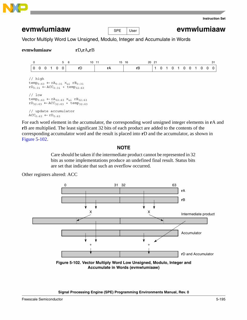
Instruction Set
Signal Processing Engine (SPE) Programming Environments Manual, Rev. 0
Freescale Semiconductor 5-195
evmwlumiaaw evmwlumiaawVector Multiply Word Low Unsigned, Modulo, Integer and Accumulate in Words
evmwlumiaaw rD,rA,rB
// hightemp0:63 ← rA0:31 ×ui rB0:31rD0:31 ← ACC0:31 + temp32:63
// lowtemp0:63 ← rA32:63 ×ui rB32:63rD32:63 ← ACC32:63 + temp32:63
// update accumulatorACC0:63 ← rD0:63
For each word element in the accumulator, the corresponding word unsigned integer elements in rA and rB are multiplied. The least significant 32 bits of each product are added to the contents of the corresponding accumulator word and the result is placed into rD and the accumulator, as shown in Figure 5-102.
NOTECare should be taken if the intermediate product cannot be represented in 32 bits as some implementations produce an undefined final result. Status bits are set that indicate that such an overflow occurred.
Other registers altered: ACC
Figure 5-102. Vector Multiply Word Low Unsigned, Modulo, Integer andAccumulate in Words (evmwlumiaaw)
0 5 6 10 11 15 16 20 21 31
0 0 0 1 0 0 rD rA rB 1 0 1 0 1 0 0 1 0 0 0
SPE User
0 31 32 63
Intermediate product
rB
X
Accumulator
rA
X
++
rD and Accumulator
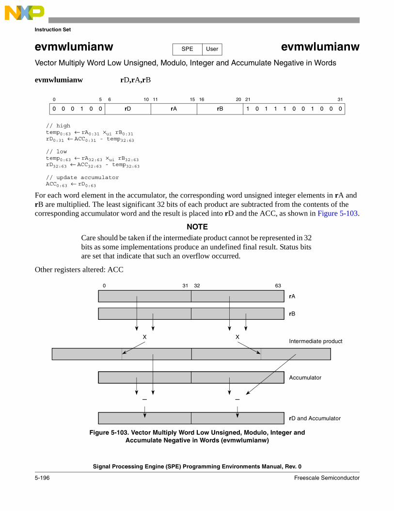
Instruction Set
Signal Processing Engine (SPE) Programming Environments Manual, Rev. 0
5-196 Freescale Semiconductor
evmwlumianw evmwlumianwVector Multiply Word Low Unsigned, Modulo, Integer and Accumulate Negative in Words
evmwlumianw rD,rA,rB
// hightemp0:63 ← rA0:31 ×ui rB0:31rD0:31 ← ACC0:31 - temp32:63
// lowtemp0:63 ← rA32:63 ×ui rB32:63rD32:63 ← ACC32:63 - temp32:63
// update accumulatorACC0:63 ← rD0:63
For each word element in the accumulator, the corresponding word unsigned integer elements in rA and rB are multiplied. The least significant 32 bits of each product are subtracted from the contents of the corresponding accumulator word and the result is placed into rD and the ACC, as shown in Figure 5-103.
NOTECare should be taken if the intermediate product cannot be represented in 32 bits as some implementations produce an undefined final result. Status bits are set that indicate that such an overflow occurred.
Other registers altered: ACC
Figure 5-103. Vector Multiply Word Low Unsigned, Modulo, Integer andAccumulate Negative in Words (evmwlumianw)
0 5 6 10 11 15 16 20 21 31
0 0 0 1 0 0 rD rA rB 1 0 1 1 1 0 0 1 0 0 0
SPE User
0 31 32 63
Intermediate product
rB
X
Accumulator
rA
X
––
rD and Accumulator
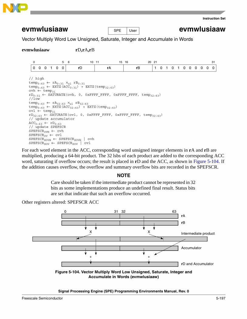
Instruction Set
Signal Processing Engine (SPE) Programming Environments Manual, Rev. 0
Freescale Semiconductor 5-197
evmwlusiaaw evmwlusiaawVector Multiply Word Low Unsigned, Saturate, Integer and Accumulate in Words
evmwlusiaaw rD,rA,rB
// hightemp0:63 ← rA0:31 ×ui rB0:31 temp0:63 ← EXTZ(ACC0:31) + EXTZ(temp32:63)ovh ← temp31rD0:31 ← SATURATE(ovh, 0, 0xFFFF_FFFF, 0xFFFF_FFFF, temp32:63) //lowtemp0:63 ← rA32:63 ×ui rB32:63 temp0:63 ← EXTZ(ACC32:63) + EXTZ(temp32:63)ovl ← temp31rD32:63 ← SATURATE(ovl, 0, 0xFFFF_FFFF, 0xFFFF_FFFF, temp32:63)// update accumulatorACC0:63 ← rD0:63// update SPEFSCRSPEFSCROVH ← ovhSPEFSCROV ← ovlSPEFSCRSOVH ← SPEFSCRSOVH | ovhSPEFSCRSOV ← SPEFSCRSOV | ovl
For each word element in the ACC, corresponding word unsigned integer elements in rA and rB are multiplied, producing a 64-bit product. The 32 lsbs of each product are added to the corresponding ACC word, saturating if overflow occurs; the result is placed in rD and the ACC, as shown in Figure 5-104. If the addition causes overflow, the overflow and summary overflow bits are recorded in the SPEFSCR.
NOTECare should be taken if the intermediate product cannot be represented in 32 bits as some implementations produce an undefined final result. Status bits are set that indicate that such an overflow occurred.
Other registers altered: SPEFSCR ACC
Figure 5-104. Vector Multiply Word Low Unsigned, Saturate, Integer andAccumulate in Words (evmwlusiaaw)
0 5 6 10 11 15 16 20 21 31
0 0 0 1 0 0 rD rA rB 1 0 1 0 1 0 0 0 0 0 0
SPE User
0 31 32 63
Intermediate product
rB
X
Accumulator
rA
X
++
rD and Accumulator
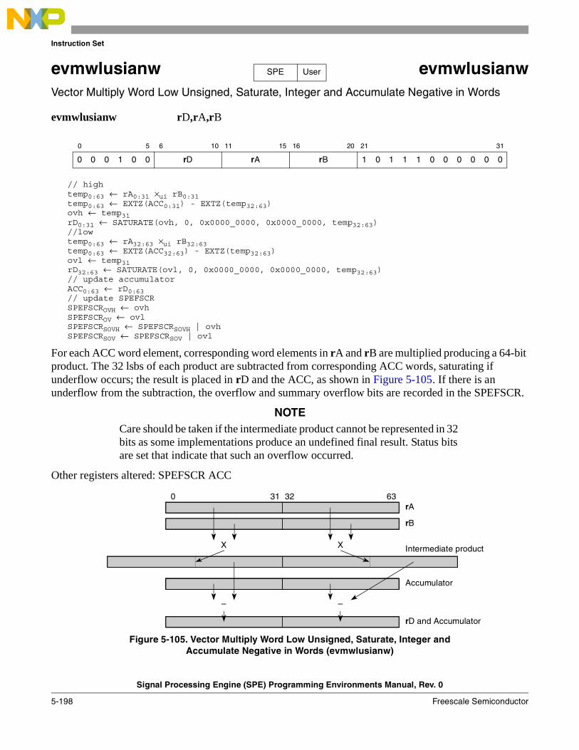
Instruction Set
Signal Processing Engine (SPE) Programming Environments Manual, Rev. 0
5-198 Freescale Semiconductor
evmwlusianw evmwlusianwVector Multiply Word Low Unsigned, Saturate, Integer and Accumulate Negative in Words
evmwlusianw rD,rA,rB
// hightemp0:63 ← rA0:31 ×ui rB0:31 temp0:63 ← EXTZ(ACC0:31) - EXTZ(temp32:63)ovh ← temp31rD0:31 ← SATURATE(ovh, 0, 0x0000_0000, 0x0000_0000, temp32:63) //lowtemp0:63 ← rA32:63 ×ui rB32:63 temp0:63 ← EXTZ(ACC32:63) - EXTZ(temp32:63)ovl ← temp31rD32:63 ← SATURATE(ovl, 0, 0x0000_0000, 0x0000_0000, temp32:63)// update accumulatorACC0:63 ← rD0:63// update SPEFSCRSPEFSCROVH ← ovhSPEFSCROV ← ovlSPEFSCRSOVH ← SPEFSCRSOVH | ovhSPEFSCRSOV ← SPEFSCRSOV | ovl
For each ACC word element, corresponding word elements in rA and rB are multiplied producing a 64-bit product. The 32 lsbs of each product are subtracted from corresponding ACC words, saturating if underflow occurs; the result is placed in rD and the ACC, as shown in Figure 5-105. If there is an underflow from the subtraction, the overflow and summary overflow bits are recorded in the SPEFSCR.
NOTECare should be taken if the intermediate product cannot be represented in 32 bits as some implementations produce an undefined final result. Status bits are set that indicate that such an overflow occurred.
Other registers altered: SPEFSCR ACC
Figure 5-105. Vector Multiply Word Low Unsigned, Saturate, Integer andAccumulate Negative in Words (evmwlusianw)
0 5 6 10 11 15 16 20 21 31
0 0 0 1 0 0 rD rA rB 1 0 1 1 1 0 0 0 0 0 0
SPE User
0 31 32 63
Intermediate product
rB
X
Accumulator
rA
X
––
rD and Accumulator
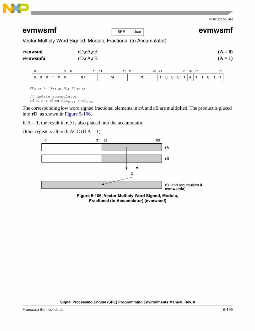
Instruction Set
Signal Processing Engine (SPE) Programming Environments Manual, Rev. 0
Freescale Semiconductor 5-199
evmwsmf evmwsmfVector Multiply Word Signed, Modulo, Fractional (to Accumulator)
evmwsmf rD,rA,rB (A = 0)evmwsmfa rD,rA,rB (A = 1)
rD0:63 ← rA32:63 ×sf rB32:63
// update accumulatorif A = 1 then ACC0:63 ← rD0:63
The corresponding low word signed fractional elements in rA and rB are multiplied. The product is placed into rD, as shown in Figure 5-106.
If A = 1, the result in rD is also placed into the accumulator.
Other registers altered: ACC (If A = 1)
Figure 5-106. Vector Multiply Word Signed, Modulo,Fractional (to Accumulator) (evmwsmf)
0 5 6 10 11 15 16 20 21 25 26 27 31
0 0 0 1 0 0 rD rA rB 1 0 0 0 1 A 1 1 0 1 1
SPE User
0 31 32 63
rD (and accumulator if
rB
X
rA
evmwsmfa)
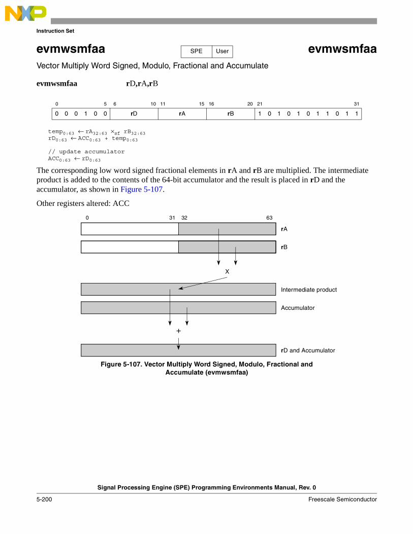
Instruction Set
Signal Processing Engine (SPE) Programming Environments Manual, Rev. 0
5-200 Freescale Semiconductor
evmwsmfaa evmwsmfaaVector Multiply Word Signed, Modulo, Fractional and Accumulate
evmwsmfaa rD,rA,rB
temp0:63 ← rA32:63 ×sf rB32:63rD0:63 ← ACC0:63 + temp0:63
// update accumulatorACC0:63 ← rD0:63
The corresponding low word signed fractional elements in rA and rB are multiplied. The intermediate product is added to the contents of the 64-bit accumulator and the result is placed in rD and the accumulator, as shown in Figure 5-107.
Other registers altered: ACC
Figure 5-107. Vector Multiply Word Signed, Modulo, Fractional andAccumulate (evmwsmfaa)
0 5 6 10 11 15 16 20 21 31
0 0 0 1 0 0 rD rA rB 1 0 1 0 1 0 1 1 0 1 1
SPE User
0 31 32 63
Intermediate product
Accumulator
rB
X
+
rD and Accumulator
rA
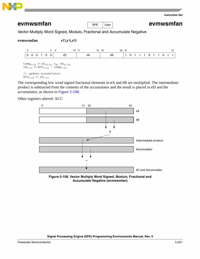
Instruction Set
Signal Processing Engine (SPE) Programming Environments Manual, Rev. 0
Freescale Semiconductor 5-201
evmwsmfan evmwsmfanVector Multiply Word Signed, Modulo, Fractional and Accumulate Negative
evmwsmfan rD,rA,rB
temp0:63 ← rA32:63 ×sf rB32:63rD0:63 ← ACC0:63 - temp0:63
// update accumulatorACC0:63 ← rD0:63
The corresponding low word signed fractional elements in rA and rB are multiplied. The intermediate product is subtracted from the contents of the accumulator and the result is placed in rD and the accumulator, as shown in Figure 5-108.
Other registers altered: ACC
Figure 5-108. Vector Multiply Word Signed, Modulo, Fractional andAccumulate Negative (evmwsmfan)
0 5 6 10 11 15 16 20 21 31
0 0 0 1 0 0 rD rA rB 1 0 1 1 1 0 1 1 0 1 1
SPE User
0 31 32 63
Intermediate product
Accumulator
rB
X
–
rD and Accumulator
rA
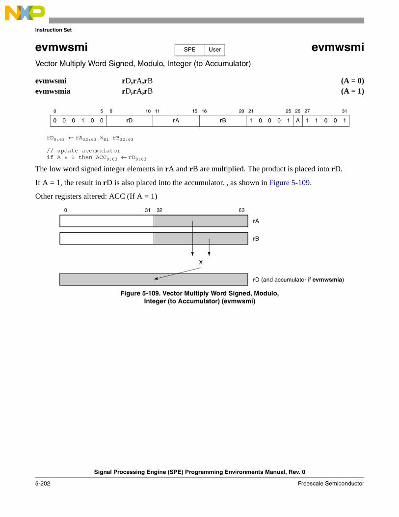
Instruction Set
Signal Processing Engine (SPE) Programming Environments Manual, Rev. 0
5-202 Freescale Semiconductor
evmwsmi evmwsmiVector Multiply Word Signed, Modulo, Integer (to Accumulator)
evmwsmi rD,rA,rB (A = 0)evmwsmia rD,rA,rB (A = 1)
rD0:63 ← rA32:63 ×si rB32:63
// update accumulatorif A = 1 then ACC0:63 ← rD0:63
The low word signed integer elements in rA and rB are multiplied. The product is placed into rD.
If A = 1, the result in rD is also placed into the accumulator. , as shown in Figure 5-109.
Other registers altered: ACC (If A = 1)
Figure 5-109. Vector Multiply Word Signed, Modulo,Integer (to Accumulator) (evmwsmi)
0 5 6 10 11 15 16 20 21 25 26 27 31
0 0 0 1 0 0 rD rA rB 1 0 0 0 1 A 1 1 0 0 1
SPE User
0 31 32 63
rD (and accumulator if evmwsmia)
rB
X
rA
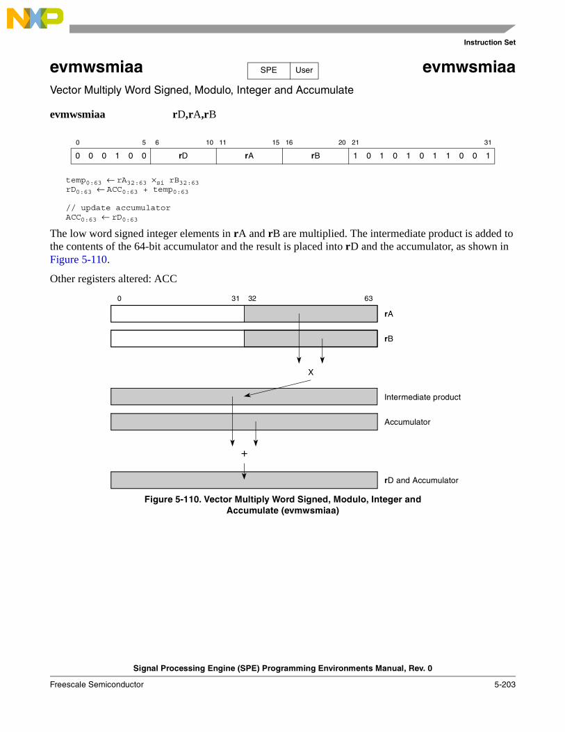
Instruction Set
Signal Processing Engine (SPE) Programming Environments Manual, Rev. 0
Freescale Semiconductor 5-203
evmwsmiaa evmwsmiaaVector Multiply Word Signed, Modulo, Integer and Accumulate
evmwsmiaa rD,rA,rB
temp0:63 ← rA32:63 ×si rB32:63rD0:63 ← ACC0:63 + temp0:63
// update accumulatorACC0:63 ← rD0:63
The low word signed integer elements in rA and rB are multiplied. The intermediate product is added to the contents of the 64-bit accumulator and the result is placed into rD and the accumulator, as shown in Figure 5-110.
Other registers altered: ACC
Figure 5-110. Vector Multiply Word Signed, Modulo, Integer andAccumulate (evmwsmiaa)
0 5 6 10 11 15 16 20 21 31
0 0 0 1 0 0 rD rA rB 1 0 1 0 1 0 1 1 0 0 1
SPE User
0 31 32 63
Intermediate product
Accumulator
rB
X
+
rD and Accumulator
rA
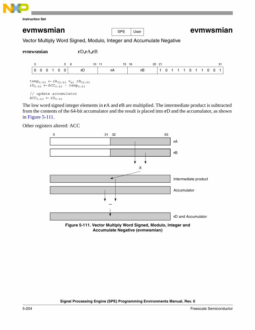
Instruction Set
Signal Processing Engine (SPE) Programming Environments Manual, Rev. 0
5-204 Freescale Semiconductor
evmwsmian evmwsmianVector Multiply Word Signed, Modulo, Integer and Accumulate Negative
evmwsmian rD,rA,rB
temp0:63 ← rA32:63 ×si rB32:63rD0:63 ← ACC0:63 - temp0:63
// update accumulatorACC0:63 ← rD0:63
The low word signed integer elements in rA and rB are multiplied. The intermediate product is subtracted from the contents of the 64-bit accumulator and the result is placed into rD and the accumulator, as shown in Figure 5-111.
Other registers altered: ACC
Figure 5-111. Vector Multiply Word Signed, Modulo, Integer andAccumulate Negative (evmwsmian)
0 5 6 10 11 15 16 20 21 31
0 0 0 1 0 0 rD rA rB 1 0 1 1 1 0 1 1 0 0 1
SPE User
0 31 32 63
Intermediate product
Accumulator
rB
X
–
rD and Accumulator
rA
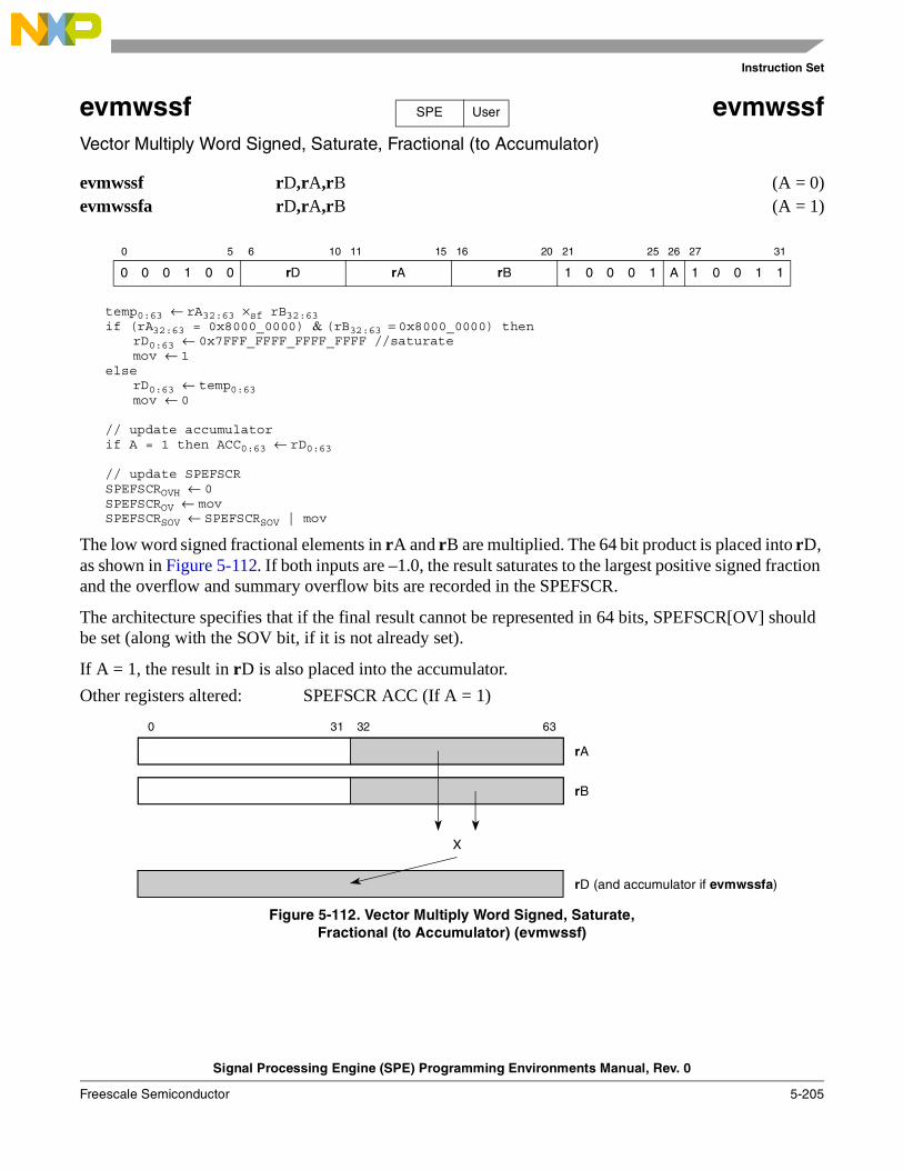
Instruction Set
Signal Processing Engine (SPE) Programming Environments Manual, Rev. 0
Freescale Semiconductor 5-205
evmwssf evmwssfVector Multiply Word Signed, Saturate, Fractional (to Accumulator)
evmwssf rD,rA,rB (A = 0)evmwssfa rD,rA,rB (A = 1)
temp0:63 ← rA32:63 ×sf rB32:63 if (rA32:63 = 0x8000_0000) & (rB32:63 = 0x8000_0000) then
rD0:63 ← 0x7FFF_FFFF_FFFF_FFFF //saturatemov ← 1
elserD0:63 ← temp0:63mov ← 0
// update accumulatorif A = 1 then ACC0:63 ← rD0:63
// update SPEFSCRSPEFSCROVH ← 0SPEFSCROV ← movSPEFSCRSOV ← SPEFSCRSOV | mov
The low word signed fractional elements in rA and rB are multiplied. The 64 bit product is placed into rD, as shown in Figure 5-112. If both inputs are –1.0, the result saturates to the largest positive signed fraction and the overflow and summary overflow bits are recorded in the SPEFSCR.
The architecture specifies that if the final result cannot be represented in 64 bits, SPEFSCR[OV] should be set (along with the SOV bit, if it is not already set).
If A = 1, the result in rD is also placed into the accumulator.
Other registers altered: SPEFSCR ACC (If A = 1)
Figure 5-112. Vector Multiply Word Signed, Saturate,Fractional (to Accumulator) (evmwssf)
0 5 6 10 11 15 16 20 21 25 26 27 31
0 0 0 1 0 0 rD rA rB 1 0 0 0 1 A 1 0 0 1 1
SPE User
0 31 32 63
rD (and accumulator if evmwssfa)
rB
X
rA
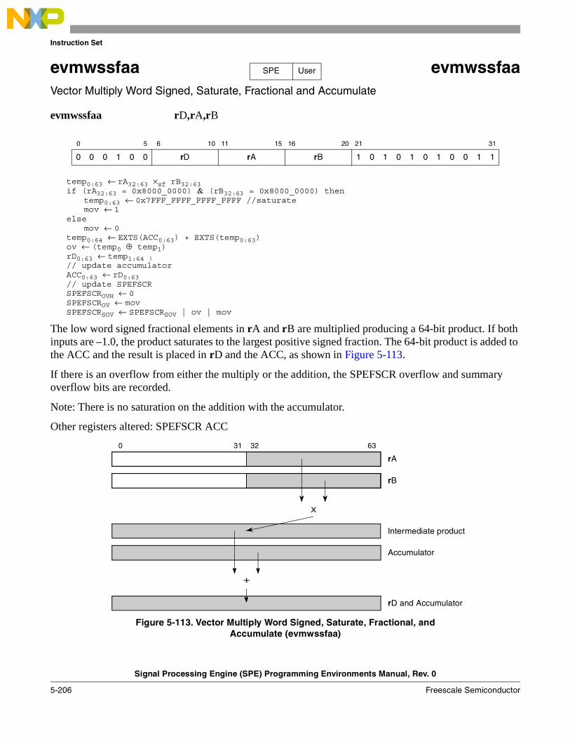
Instruction Set
Signal Processing Engine (SPE) Programming Environments Manual, Rev. 0
5-206 Freescale Semiconductor
evmwssfaa evmwssfaaVector Multiply Word Signed, Saturate, Fractional and Accumulate
evmwssfaa rD,rA,rB
temp0:63 ← rA32:63 ×sf rB32:63 if (rA32:63 = 0x8000_0000) & (rB32:63 = 0x8000_0000) then
temp0:63 ← 0x7FFF_FFFF_FFFF_FFFF //saturate mov ← 1
elsemov ← 0
temp0:64 ← EXTS(ACC0:63) + EXTS(temp0:63)ov ← (temp0 ⊕ temp1)rD0:63 ← temp1:64 ) // update accumulatorACC0:63 ← rD0:63// update SPEFSCRSPEFSCROVH ← 0SPEFSCROV ← movSPEFSCRSOV ← SPEFSCRSOV | ov | mov
The low word signed fractional elements in rA and rB are multiplied producing a 64-bit product. If both inputs are –1.0, the product saturates to the largest positive signed fraction. The 64-bit product is added to the ACC and the result is placed in rD and the ACC, as shown in Figure 5-113.
If there is an overflow from either the multiply or the addition, the SPEFSCR overflow and summary overflow bits are recorded.
Note: There is no saturation on the addition with the accumulator.
Other registers altered: SPEFSCR ACC
Figure 5-113. Vector Multiply Word Signed, Saturate, Fractional, andAccumulate (evmwssfaa)
0 5 6 10 11 15 16 20 21 31
0 0 0 1 0 0 rD rA rB 1 0 1 0 1 0 1 0 0 1 1
SPE User
0 31 32 63
Intermediate product
Accumulator
rB
X
+
rD and Accumulator
rA
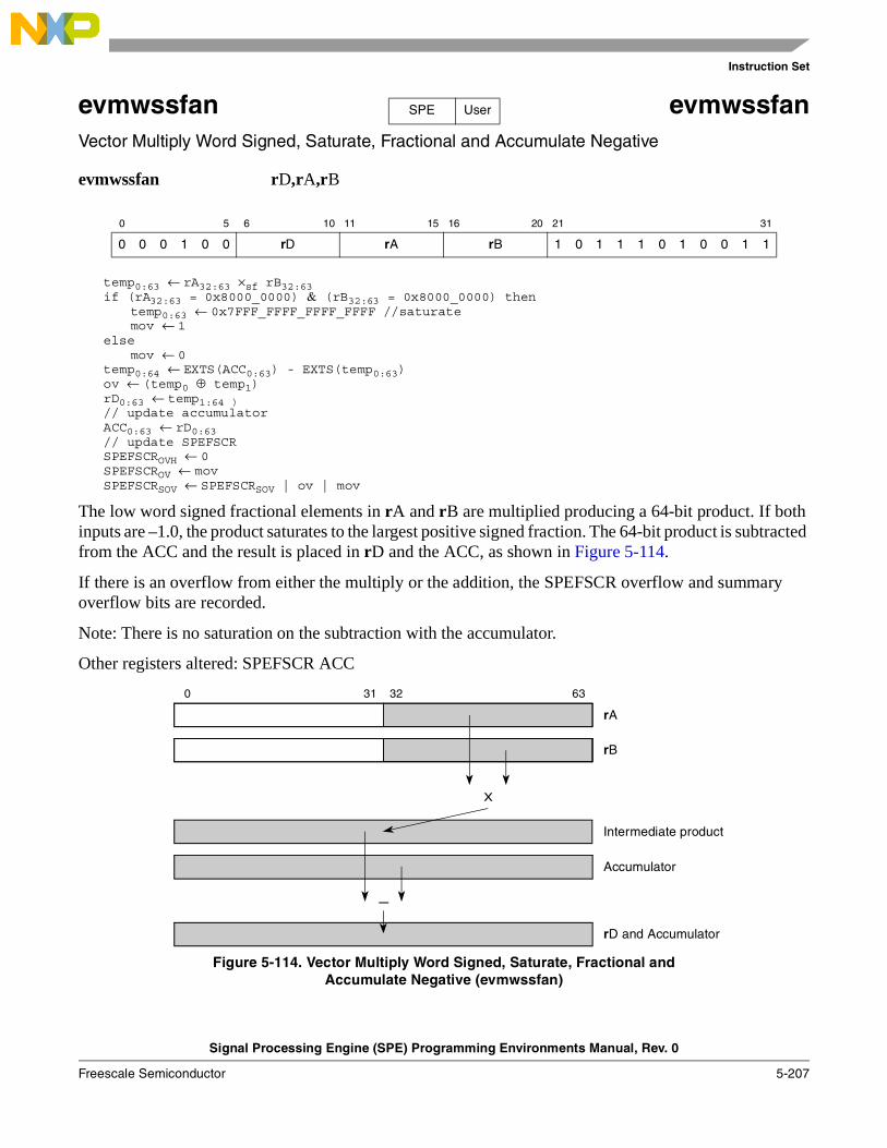
Instruction Set
Signal Processing Engine (SPE) Programming Environments Manual, Rev. 0
Freescale Semiconductor 5-207
evmwssfan evmwssfanVector Multiply Word Signed, Saturate, Fractional and Accumulate Negative
evmwssfan rD,rA,rB
temp0:63 ← rA32:63 ×sf rB32:63 if (rA32:63 = 0x8000_0000) & (rB32:63 = 0x8000_0000) then
temp0:63 ← 0x7FFF_FFFF_FFFF_FFFF //saturate mov ← 1
elsemov ← 0
temp0:64 ← EXTS(ACC0:63) - EXTS(temp0:63)ov ← (temp0 ⊕ temp1)rD0:63 ← temp1:64 ) // update accumulatorACC0:63 ← rD0:63// update SPEFSCRSPEFSCROVH ← 0SPEFSCROV ← movSPEFSCRSOV ← SPEFSCRSOV | ov | mov
The low word signed fractional elements in rA and rB are multiplied producing a 64-bit product. If both inputs are –1.0, the product saturates to the largest positive signed fraction. The 64-bit product is subtracted from the ACC and the result is placed in rD and the ACC, as shown in Figure 5-114.
If there is an overflow from either the multiply or the addition, the SPEFSCR overflow and summary overflow bits are recorded.
Note: There is no saturation on the subtraction with the accumulator.
Other registers altered: SPEFSCR ACC
Figure 5-114. Vector Multiply Word Signed, Saturate, Fractional andAccumulate Negative (evmwssfan)
0 5 6 10 11 15 16 20 21 31
0 0 0 1 0 0 rD rA rB 1 0 1 1 1 0 1 0 0 1 1
SPE User
0 31 32 63
Intermediate product
Accumulator
rB
X
–
rD and Accumulator
rA
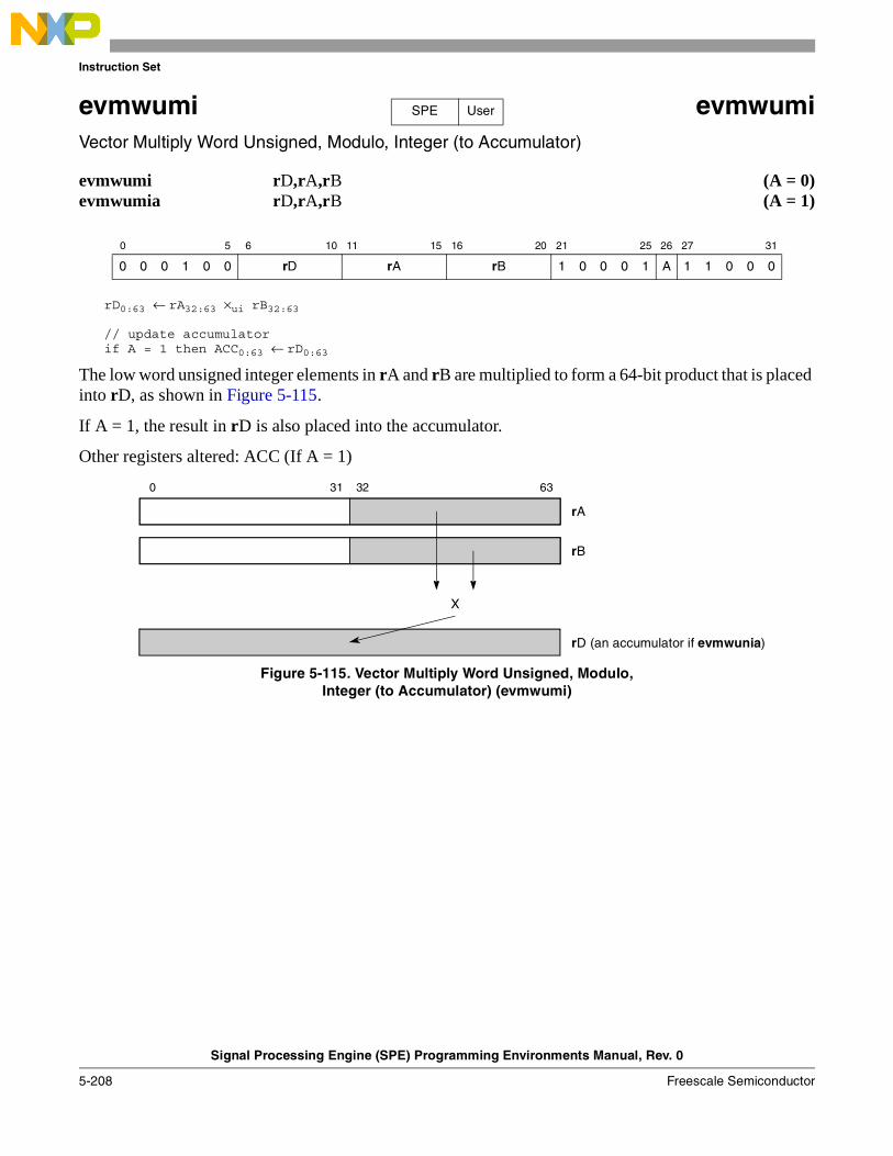
Instruction Set
Signal Processing Engine (SPE) Programming Environments Manual, Rev. 0
5-208 Freescale Semiconductor
evmwumi evmwumiVector Multiply Word Unsigned, Modulo, Integer (to Accumulator)
evmwumi rD,rA,rB (A = 0)evmwumia rD,rA,rB (A = 1)
rD0:63 ← rA32:63 ×ui rB32:63
// update accumulatorif A = 1 then ACC0:63 ← rD0:63
The low word unsigned integer elements in rA and rB are multiplied to form a 64-bit product that is placed into rD, as shown in Figure 5-115.
If A = 1, the result in rD is also placed into the accumulator.
Other registers altered: ACC (If A = 1)
Figure 5-115. Vector Multiply Word Unsigned, Modulo,Integer (to Accumulator) (evmwumi)
0 5 6 10 11 15 16 20 21 25 26 27 31
0 0 0 1 0 0 rD rA rB 1 0 0 0 1 A 1 1 0 0 0
SPE User
0 31 32 63
rD (an accumulator if evmwunia)
rB
X
rA
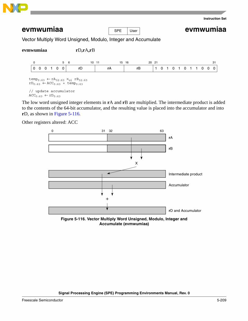
Instruction Set
Signal Processing Engine (SPE) Programming Environments Manual, Rev. 0
Freescale Semiconductor 5-209
evmwumiaa evmwumiaaVector Multiply Word Unsigned, Modulo, Integer and Accumulate
evmwumiaa rD,rA,rB
temp0:63 ← rA32:63 ×ui rB32:63rD0:63 ← ACC0:63 + temp0:63
// update accumulatorACC0:63 ← rD0:63
The low word unsigned integer elements in rA and rB are multiplied. The intermediate product is added to the contents of the 64-bit accumulator, and the resulting value is placed into the accumulator and into rD, as shown in Figure 5-116.
Other registers altered: ACC
Figure 5-116. Vector Multiply Word Unsigned, Modulo, Integer andAccumulate (evmwumiaa)
0 5 6 10 11 15 16 20 21 31
0 0 0 1 0 0 rD rA rB 1 0 1 0 1 0 1 1 0 0 0
SPE User
0 31 32 63
Intermediate product
Accumulator
rB
X
+
rD and Accumulator
rA
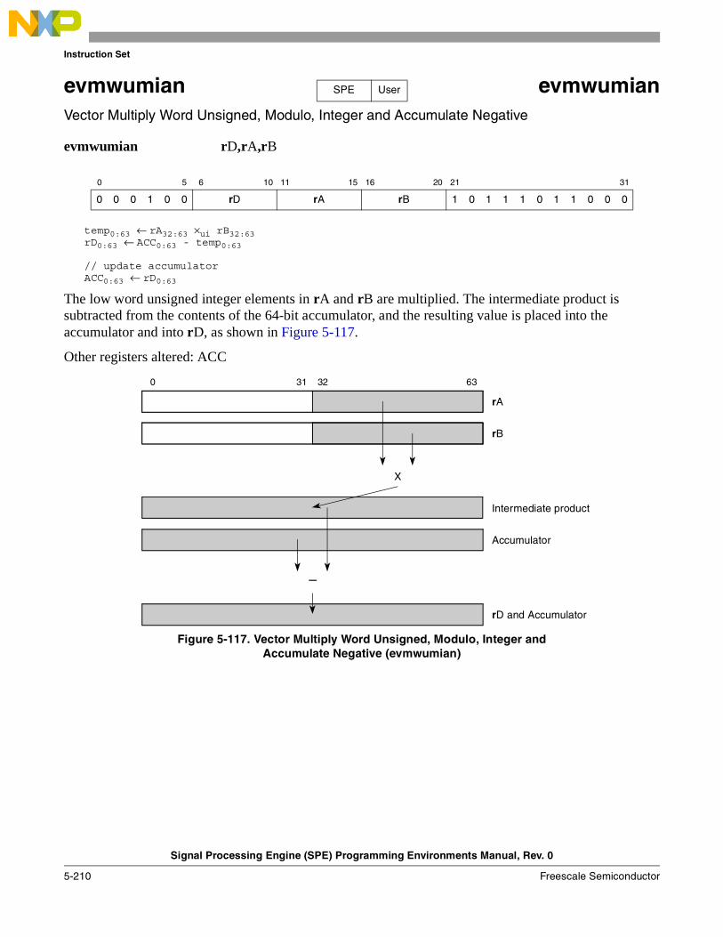
Instruction Set
Signal Processing Engine (SPE) Programming Environments Manual, Rev. 0
5-210 Freescale Semiconductor
evmwumian evmwumianVector Multiply Word Unsigned, Modulo, Integer and Accumulate Negative
evmwumian rD,rA,rB
temp0:63 ← rA32:63 ×ui rB32:63rD0:63 ← ACC0:63 - temp0:63
// update accumulatorACC0:63 ← rD0:63
The low word unsigned integer elements in rA and rB are multiplied. The intermediate product is subtracted from the contents of the 64-bit accumulator, and the resulting value is placed into the accumulator and into rD, as shown in Figure 5-117.
Other registers altered: ACC
Figure 5-117. Vector Multiply Word Unsigned, Modulo, Integer andAccumulate Negative (evmwumian)
0 5 6 10 11 15 16 20 21 31
0 0 0 1 0 0 rD rA rB 1 0 1 1 1 0 1 1 0 0 0
SPE User
0 31 32 63
Intermediate product
Accumulator
rB
X
–
rD and Accumulator
rA
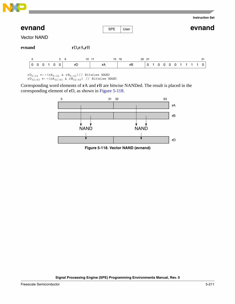
Instruction Set
Signal Processing Engine (SPE) Programming Environments Manual, Rev. 0
Freescale Semiconductor 5-211
evnand evnandVector NAND
evnand rD,rA,rB
rD0:31 ← ¬(rA0:31 & rB0:31)// Bitwise NANDrD32:63 ← ¬(rA32:63 & rB32:63) // Bitwise NAND
Corresponding word elements of rA and rB are bitwise NANDed. The result is placed in the corresponding element of rD, as shown in Figure 5-118.
Figure 5-118. Vector NAND (evnand)
0 5 6 10 11 15 16 20 21 31
0 0 0 1 0 0 rD rA rB 0 1 0 0 0 0 1 1 1 1 0
SPE User
0 31 32 63
rA
rB
NAND NAND
rD
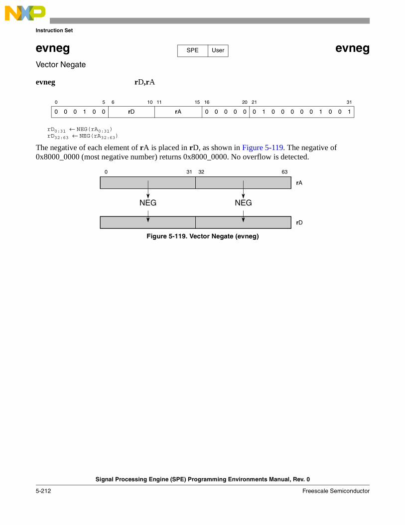
Instruction Set
Signal Processing Engine (SPE) Programming Environments Manual, Rev. 0
5-212 Freescale Semiconductor
evneg evnegVector Negate
evneg rD,rA
rD0:31 ← NEG(rA0:31)rD32:63 ← NEG(rA32:63)
The negative of each element of rA is placed in rD, as shown in Figure 5-119. The negative of 0x8000_0000 (most negative number) returns 0x8000_0000. No overflow is detected.
Figure 5-119. Vector Negate (evneg)
0 5 6 10 11 15 16 20 21 31
0 0 0 1 0 0 rD rA 0 0 0 0 0 0 1 0 0 0 0 0 1 0 0 1
SPE User
0 31 32 63
rA
NEG NEG
rD
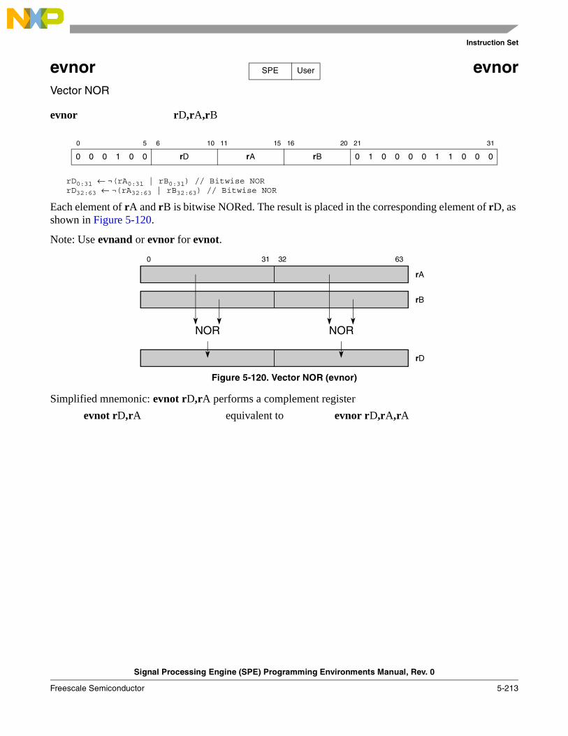
Instruction Set
Signal Processing Engine (SPE) Programming Environments Manual, Rev. 0
Freescale Semiconductor 5-213
evnor evnorVector NOR
evnor rD,rA,rB
rD0:31 ← ¬(rA0:31 | rB0:31) // Bitwise NORrD32:63 ← ¬(rA32:63 | rB32:63) // Bitwise NOR
Each element of rA and rB is bitwise NORed. The result is placed in the corresponding element of rD, as shown in Figure 5-120.
Note: Use evnand or evnor for evnot.
Figure 5-120. Vector NOR (evnor)
Simplified mnemonic: evnot rD,rA performs a complement register
evnot rD,rA equivalent to evnor rD,rA,rA
0 5 6 10 11 15 16 20 21 31
0 0 0 1 0 0 rD rA rB 0 1 0 0 0 0 1 1 0 0 0
SPE User
0 31 32 63
rA
rB
NOR NOR
rD
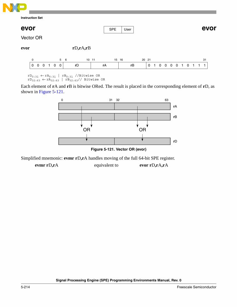
Instruction Set
Signal Processing Engine (SPE) Programming Environments Manual, Rev. 0
5-214 Freescale Semiconductor
evor evorVector OR
evor rD,rA,rB
rD0:31 ← rA0:31 | rB0:31 //Bitwise ORrD32:63 ← rA32:63 | rB32:63// Bitwise OR
Each element of rA and rB is bitwise ORed. The result is placed in the corresponding element of rD, as shown in Figure 5-121.
Figure 5-121. Vector OR (evor)
Simplified mnemonic: evmr rD,rA handles moving of the full 64-bit SPE register.
evmr rD,rA equivalent to evor rD,rA,rA
0 5 6 10 11 15 16 20 21 31
0 0 0 1 0 0 rD rA rB 0 1 0 0 0 0 1 0 1 1 1
SPE User
0 31 32 63
rA
rB
OR OR
rD
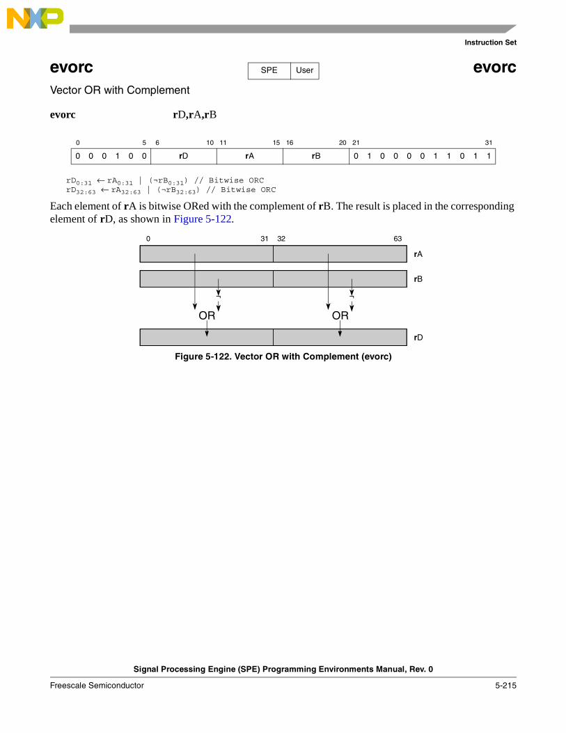
Instruction Set
Signal Processing Engine (SPE) Programming Environments Manual, Rev. 0
Freescale Semiconductor 5-215
evorc evorcVector OR with Complement
evorc rD,rA,rB
rD0:31 ← rA0:31 | (¬rB0:31) // Bitwise ORCrD32:63 ← rA32:63 | (¬rB32:63) // Bitwise ORC
Each element of rA is bitwise ORed with the complement of rB. The result is placed in the corresponding element of rD, as shown in Figure 5-122.
Figure 5-122. Vector OR with Complement (evorc)
0 5 6 10 11 15 16 20 21 31
0 0 0 1 0 0 rD rA rB 0 1 0 0 0 0 1 1 0 1 1
SPE User
0 31 32 63
rA
rB
OR OR
rD
¬¬
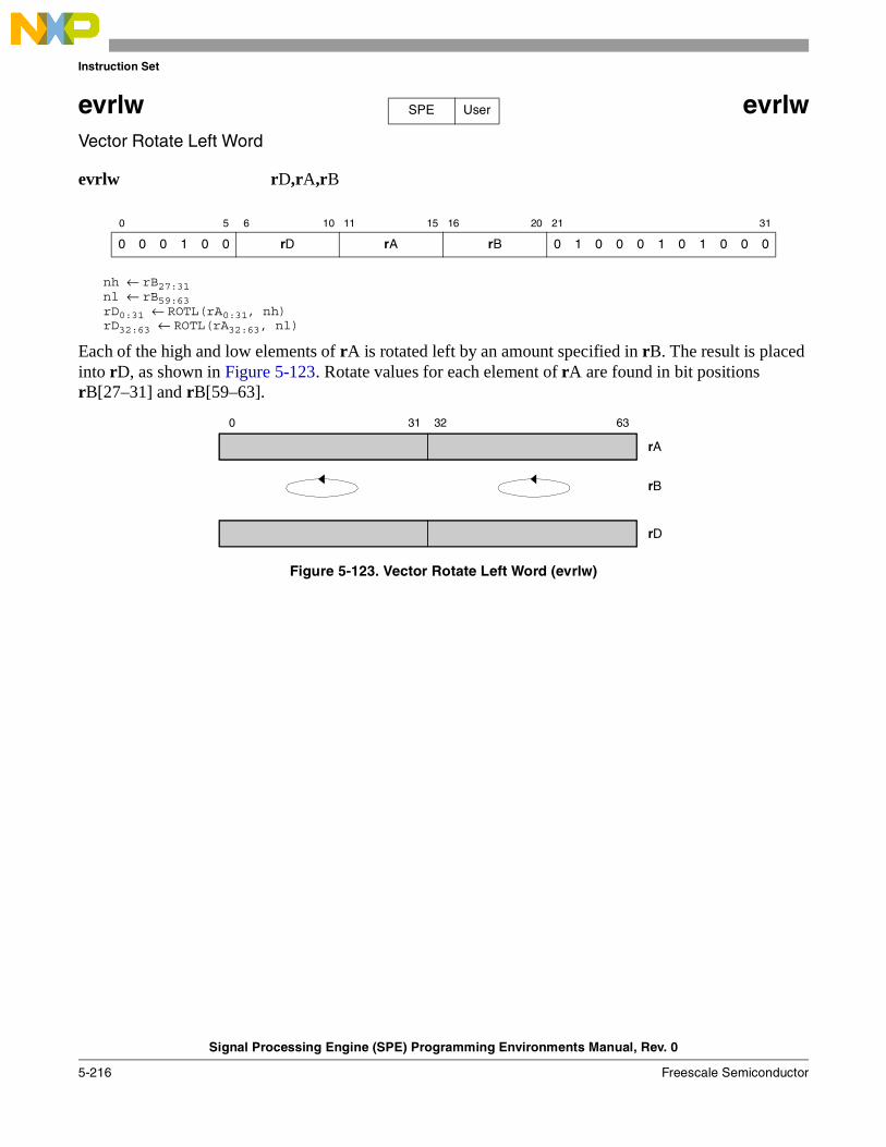
Instruction Set
Signal Processing Engine (SPE) Programming Environments Manual, Rev. 0
5-216 Freescale Semiconductor
evrlw evrlwVector Rotate Left Word
evrlw rD,rA,rB
nh ← rB27:31nl ← rB59:63rD0:31 ← ROTL(rA0:31, nh)rD32:63 ← ROTL(rA32:63, nl)
Each of the high and low elements of rA is rotated left by an amount specified in rB. The result is placed into rD, as shown in Figure 5-123. Rotate values for each element of rA are found in bit positions rB[27–31] and rB[59–63].
Figure 5-123. Vector Rotate Left Word (evrlw)
0 5 6 10 11 15 16 20 21 31
0 0 0 1 0 0 rD rA rB 0 1 0 0 0 1 0 1 0 0 0
SPE User
0 31 32 63
rA
rB
rD
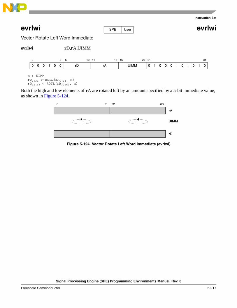
Instruction Set
Signal Processing Engine (SPE) Programming Environments Manual, Rev. 0
Freescale Semiconductor 5-217
evrlwi evrlwiVector Rotate Left Word Immediate
evrlwi rD,rA,UIMM
n ← UIMMrD0:31 ← ROTL(rA0:31, n)rD32:63 ← ROTL(rA32:63, n)
Both the high and low elements of rA are rotated left by an amount specified by a 5-bit immediate value, as shown in Figure 5-124.
Figure 5-124. Vector Rotate Left Word Immediate (evrlwi)
0 5 6 10 11 15 16 20 21 31
0 0 0 1 0 0 rD rA UIMM 0 1 0 0 0 1 0 1 0 1 0
SPE User
0 31 32 63
rA
UIMM
rD
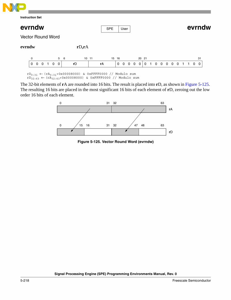
Instruction Set
Signal Processing Engine (SPE) Programming Environments Manual, Rev. 0
5-218 Freescale Semiconductor
evrndw evrndwVector Round Word
evrndw rD,rA
rD0:31 ← (rA0:31+0x00008000) & 0xFFFF0000 // Modulo sumrD32:63 ← (rA32:63+0x00008000) & 0xFFFF0000 // Modulo sum
The 32-bit elements of rA are rounded into 16 bits. The result is placed into rD, as shown in Figure 5-125. The resulting 16 bits are placed in the most significant 16 bits of each element of rD, zeroing out the low order 16 bits of each element.
Figure 5-125. Vector Round Word (evrndw)
0 5 6 10 11 15 16 20 21 31
0 0 0 1 0 0 rD rA 0 0 0 0 0 0 1 0 0 0 0 0 1 1 0 0
SPE User
0 31 32 63
rA
rD
0 31 32 6315 16 47 48
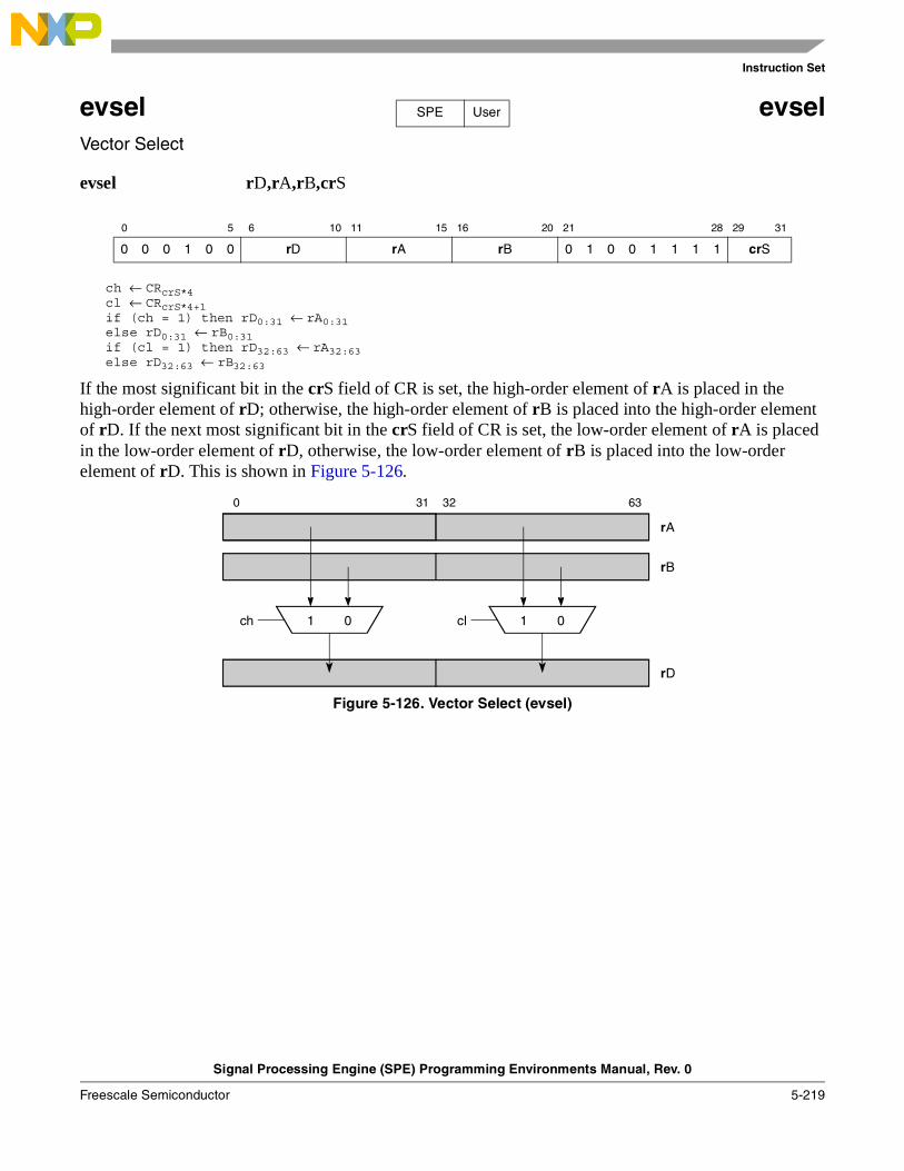
Instruction Set
Signal Processing Engine (SPE) Programming Environments Manual, Rev. 0
Freescale Semiconductor 5-219
evsel evselVector Select
evsel rD,rA,rB,crS
ch ← CRcrS*4cl ← CRcrS*4+1if (ch = 1) then rD0:31 ← rA0:31else rD0:31 ← rB0:31if (cl = 1) then rD32:63 ← rA32:63else rD32:63 ← rB32:63
If the most significant bit in the crS field of CR is set, the high-order element of rA is placed in the high-order element of rD; otherwise, the high-order element of rB is placed into the high-order element of rD. If the next most significant bit in the crS field of CR is set, the low-order element of rA is placed in the low-order element of rD, otherwise, the low-order element of rB is placed into the low-order element of rD. This is shown in Figure 5-126.
Figure 5-126. Vector Select (evsel)
0 5 6 10 11 15 16 20 21 28 29 31
0 0 0 1 0 0 rD rA rB 0 1 0 0 1 1 1 1 crS
SPE User
0 31 32 63
rA
rB
rD
clch 1 0 01
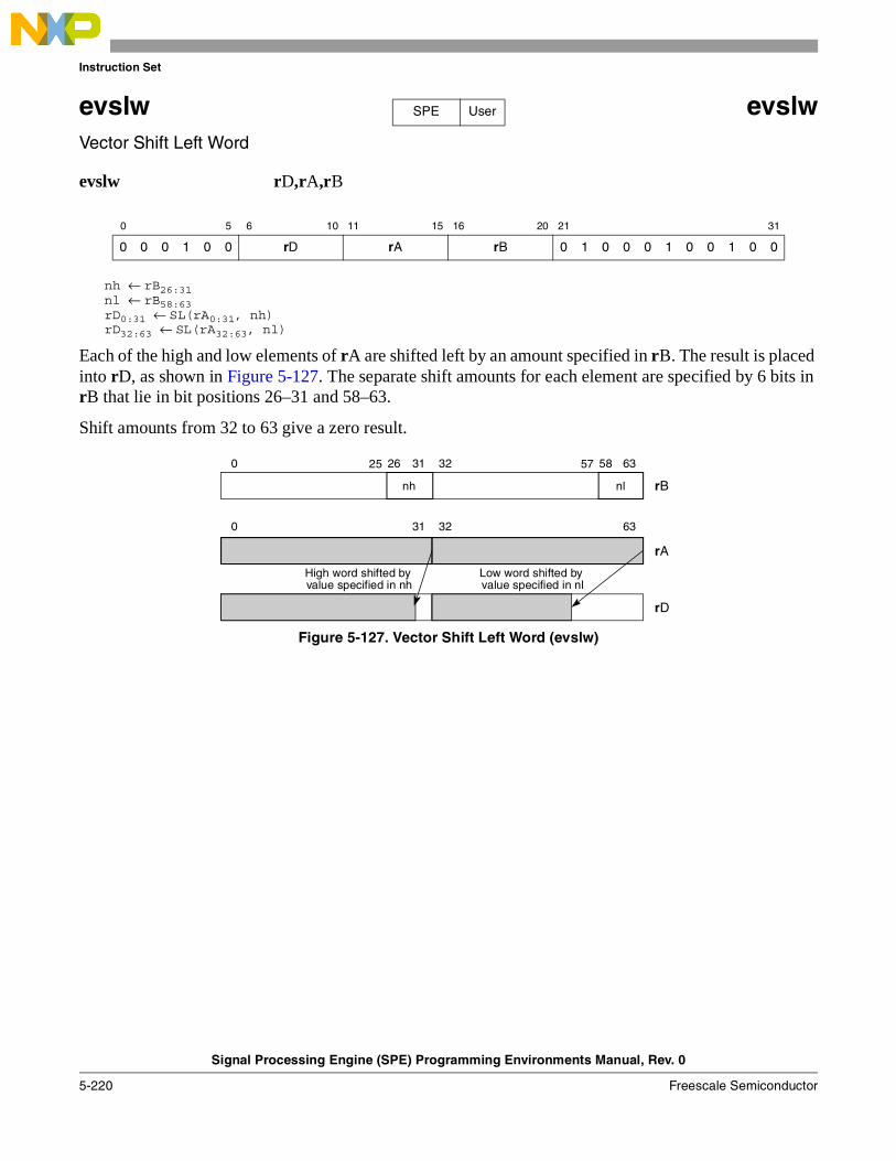
Instruction Set
Signal Processing Engine (SPE) Programming Environments Manual, Rev. 0
5-220 Freescale Semiconductor
evslw evslwVector Shift Left Word
evslw rD,rA,rB
nh ← rB26:31nl ← rB58:63rD0:31 ← SL(rA0:31, nh)rD32:63 ← SL(rA32:63, nl)
Each of the high and low elements of rA are shifted left by an amount specified in rB. The result is placed into rD, as shown in Figure 5-127. The separate shift amounts for each element are specified by 6 bits in rB that lie in bit positions 26–31 and 58–63.
Shift amounts from 32 to 63 give a zero result.
Figure 5-127. Vector Shift Left Word (evslw)
0 5 6 10 11 15 16 20 21 31
0 0 0 1 0 0 rD rA rB 0 1 0 0 0 1 0 0 1 0 0
SPE User
0 31 32 63
rA
rB
rD
nh nl
0 31 32 6326 58
High word shifted by value specified in nh
Low word shifted by value specified in nl
25 57
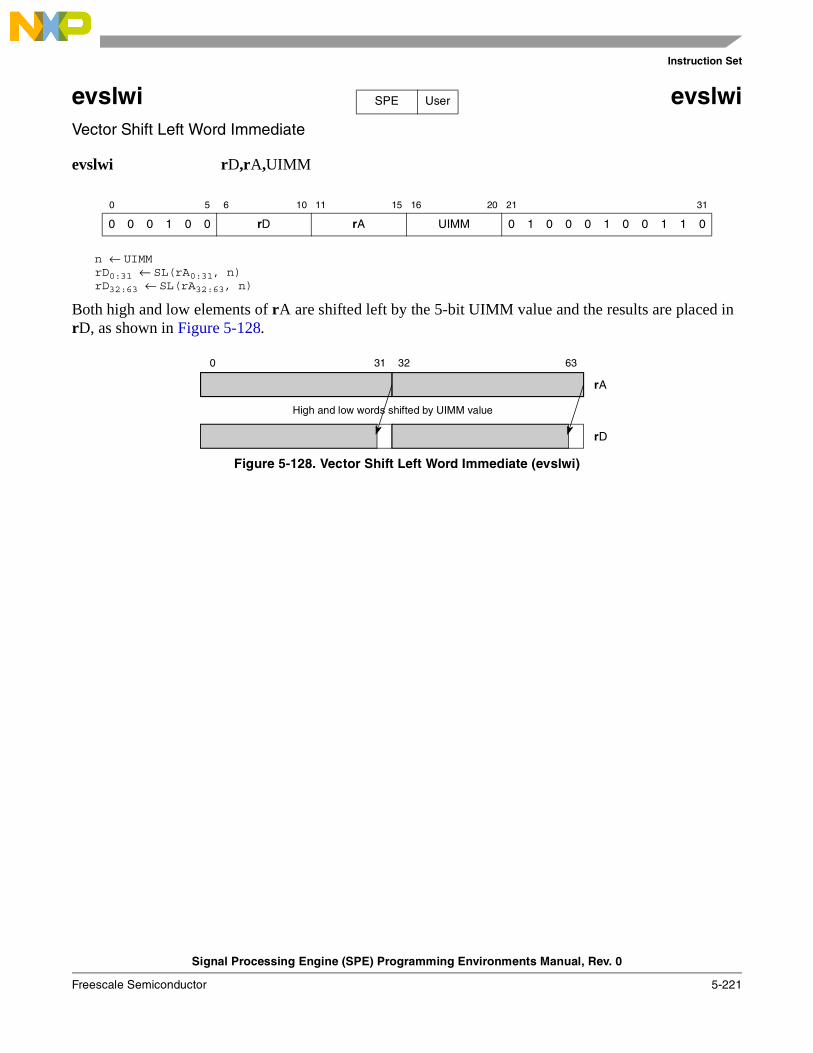
Instruction Set
Signal Processing Engine (SPE) Programming Environments Manual, Rev. 0
Freescale Semiconductor 5-221
evslwi evslwiVector Shift Left Word Immediate
evslwi rD,rA,UIMM
n ← UIMMrD0:31 ← SL(rA0:31, n)rD32:63 ← SL(rA32:63, n)
Both high and low elements of rA are shifted left by the 5-bit UIMM value and the results are placed in rD, as shown in Figure 5-128.
Figure 5-128. Vector Shift Left Word Immediate (evslwi)
0 5 6 10 11 15 16 20 21 31
0 0 0 1 0 0 rD rA UIMM 0 1 0 0 0 1 0 0 1 1 0
SPE User
0 31 32 63
rA
rD
High and low words shifted by UIMM value
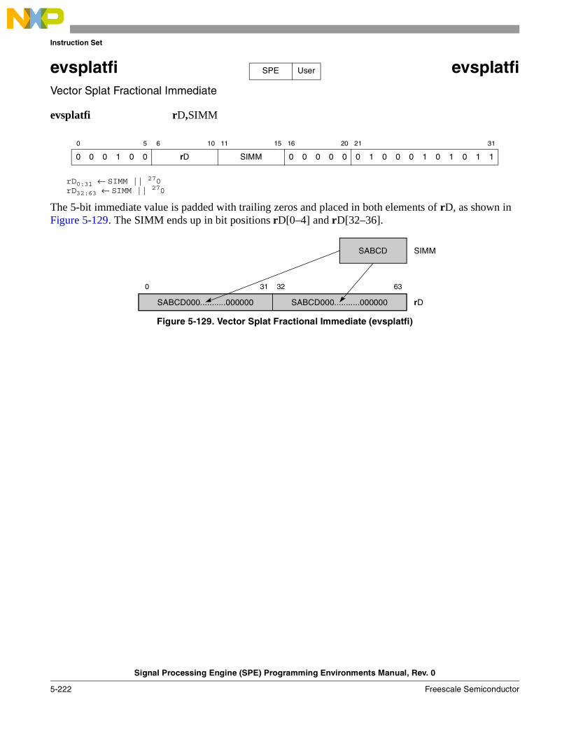
Instruction Set
Signal Processing Engine (SPE) Programming Environments Manual, Rev. 0
5-222 Freescale Semiconductor
evsplatfi evsplatfiVector Splat Fractional Immediate
evsplatfi rD,SIMM
rD0:31 ← SIMM || 270rD32:63 ← SIMM || 270
The 5-bit immediate value is padded with trailing zeros and placed in both elements of rD, as shown in Figure 5-129. The SIMM ends up in bit positions rD[0–4] and rD[32–36].
Figure 5-129. Vector Splat Fractional Immediate (evsplatfi)
0 5 6 10 11 15 16 20 21 31
0 0 0 1 0 0 rD SIMM 0 0 0 0 0 0 1 0 0 0 1 0 1 0 1 1
SPE User
SIMM
rD
0 31 32 63
SABCD
SABCD000...........000000 SABCD000...........000000
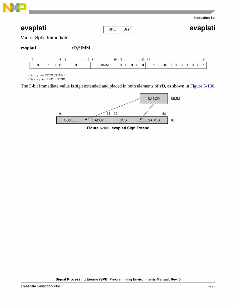
Instruction Set
Signal Processing Engine (SPE) Programming Environments Manual, Rev. 0
Freescale Semiconductor 5-223
evsplati evsplatiVector Splat Immediate
evsplati rD,SIMM
rD0:31 ← EXTS(SIMM)rD32:63 ← EXTS(SIMM)
The 5-bit immediate value is sign extended and placed in both elements of rD, as shown in Figure 5-130.
Figure 5-130. evsplati Sign Extend
0 5 6 10 11 15 16 20 21 31
0 0 0 1 0 0 rD SIMM 0 0 0 0 0 0 1 0 0 0 1 0 1 0 0 1
SPE User
SIMM
rD
0 31 32 63
SABCD
SSS......................SABCDSSS......................SABCD
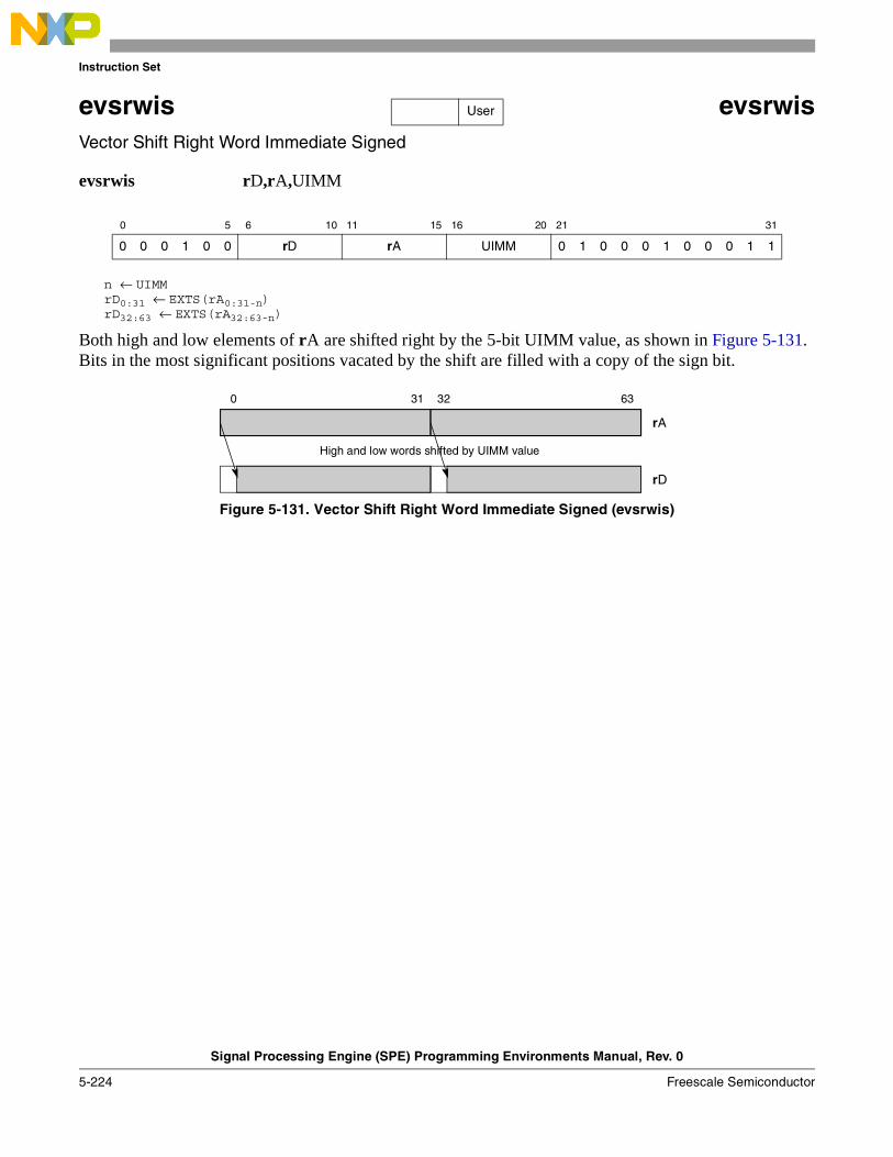
Instruction Set
Signal Processing Engine (SPE) Programming Environments Manual, Rev. 0
5-224 Freescale Semiconductor
evsrwis evsrwisVector Shift Right Word Immediate Signed
evsrwis rD,rA,UIMM
n ← UIMMrD0:31 ← EXTS(rA0:31-n)rD32:63 ← EXTS(rA32:63-n)
Both high and low elements of rA are shifted right by the 5-bit UIMM value, as shown in Figure 5-131. Bits in the most significant positions vacated by the shift are filled with a copy of the sign bit.
Figure 5-131. Vector Shift Right Word Immediate Signed (evsrwis)
0 5 6 10 11 15 16 20 21 31
0 0 0 1 0 0 rD rA UIMM 0 1 0 0 0 1 0 0 0 1 1
User
0 31 32 63
rA
rD
High and low words shifted by UIMM value
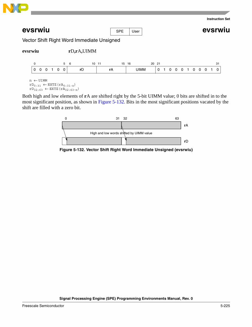
Instruction Set
Signal Processing Engine (SPE) Programming Environments Manual, Rev. 0
Freescale Semiconductor 5-225
evsrwiu evsrwiuVector Shift Right Word Immediate Unsigned
evsrwiu rD,rA,UIMM
n ← UIMMrD0:31 ← EXTZ(rA0:31-n)rD32:63 ← EXTZ(rA32:63-n)
Both high and low elements of rA are shifted right by the 5-bit UIMM value; 0 bits are shifted in to the most significant position, as shown in Figure 5-132. Bits in the most significant positions vacated by the shift are filled with a zero bit.
Figure 5-132. Vector Shift Right Word Immediate Unsigned (evsrwiu)
0 5 6 10 11 15 16 20 21 31
0 0 0 1 0 0 rD rA UIMM 0 1 0 0 0 1 0 0 0 1 0
SPE User
0 31 32 63
rA
rD
High and low words shifted by UIMM value
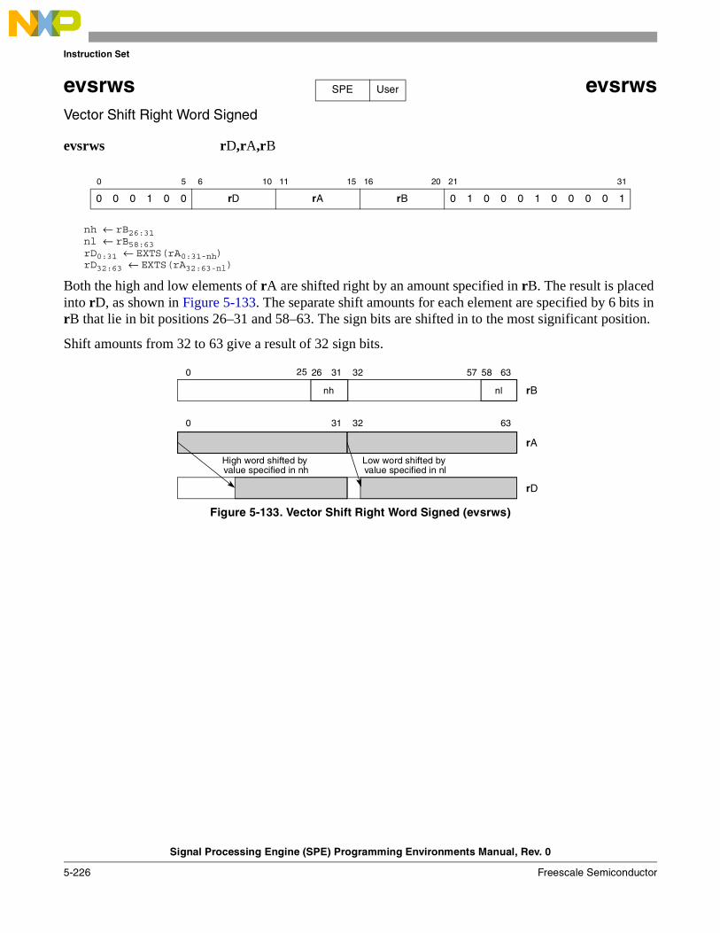
Instruction Set
Signal Processing Engine (SPE) Programming Environments Manual, Rev. 0
5-226 Freescale Semiconductor
evsrws evsrwsVector Shift Right Word Signed
evsrws rD,rA,rB
nh ← rB26:31nl ← rB58:63rD0:31 ← EXTS(rA0:31-nh)rD32:63 ← EXTS(rA32:63-nl)
Both the high and low elements of rA are shifted right by an amount specified in rB. The result is placed into rD, as shown in Figure 5-133. The separate shift amounts for each element are specified by 6 bits in rB that lie in bit positions 26–31 and 58–63. The sign bits are shifted in to the most significant position.
Shift amounts from 32 to 63 give a result of 32 sign bits.
Figure 5-133. Vector Shift Right Word Signed (evsrws)
0 5 6 10 11 15 16 20 21 31
0 0 0 1 0 0 rD rA rB 0 1 0 0 0 1 0 0 0 0 1
SPE User
0 31 32 63
rA
rB
rD
nh nl
0 31 32 6326 58
Low word shifted by value specified in nl
High word shifted by value specified in nh
25 57
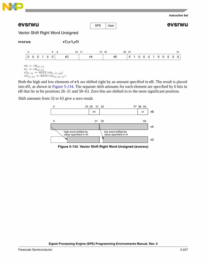
Instruction Set
Signal Processing Engine (SPE) Programming Environments Manual, Rev. 0
Freescale Semiconductor 5-227
evsrwu evsrwuVector Shift Right Word Unsigned
evsrwu rD,rA,rB
nh ← rB26:31nl ← rB58:63rD0:31 ← EXTZ(rA0:31-nh)rD32:63 ← EXTZ(rA32:63-nl)
Both the high and low elements of rA are shifted right by an amount specified in rB. The result is placed into rD, as shown in Figure 5-134. The separate shift amounts for each element are specified by 6 bits in rB that lie in bit positions 26–31 and 58–63. Zero bits are shifted in to the most significant position.
Shift amounts from 32 to 63 give a zero result.
Figure 5-134. Vector Shift Right Word Unsigned (evsrwu)
0 5 6 10 11 15 16 20 21 31
0 0 0 1 0 0 rD rA rB 0 1 0 0 0 1 0 0 0 0 0
SPE User
0 31 32 63
rA
rB
rD
nh nl
0 31 32 6326 58
low word shifted by value specified in nl
high word shifted by value specified in nh
5725
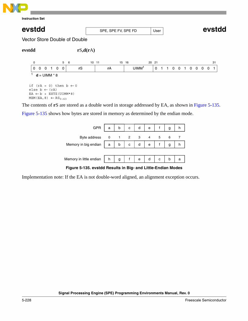
Instruction Set
Signal Processing Engine (SPE) Programming Environments Manual, Rev. 0
5-228 Freescale Semiconductor
evstdd evstddVector Store Double of Double
evstdd rS,d(rA)
if (rA = 0) then b ← 0else b ← (rA)EA ← b + EXTZ(UIMM*8)MEM(EA,8) ← RS0:63
The contents of rS are stored as a double word in storage addressed by EA, as shown in Figure 5-135.
Figure 5-135 shows how bytes are stored in memory as determined by the endian mode.
Figure 5-135. evstdd Results in Big- and Little-Endian Modes
Implementation note: If the EA is not double-word aligned, an alignment exception occurs.
0 5 6 10 11 15 16 20 21 31
0 0 0 1 0 0 rS rA UIMM1
1 d = UIMM * 8
0 1 1 0 0 1 0 0 0 0 1
SPE, SPE FV, SPE FD User
c d e f ha b g
0 1 2 3 4 5 6 7
c d e f ha b g
f e d c ah g b
GPR
Memory in big endian
Memory in little endian
Byte address
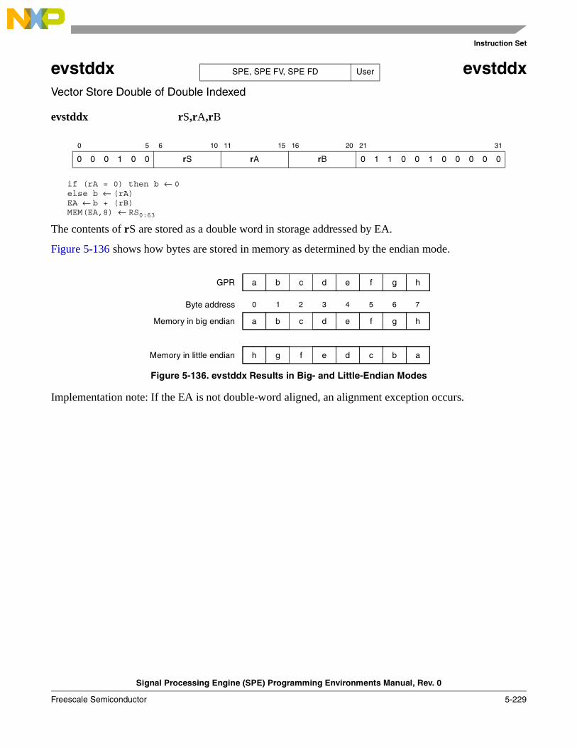
Instruction Set
Signal Processing Engine (SPE) Programming Environments Manual, Rev. 0
Freescale Semiconductor 5-229
evstddx evstddxVector Store Double of Double Indexed
evstddx rS,rA,rB
if (rA = 0) then b ← 0else b ← (rA)EA ← b + (rB)MEM(EA,8) ← RS0:63
The contents of rS are stored as a double word in storage addressed by EA.
Figure 5-136 shows how bytes are stored in memory as determined by the endian mode.
Figure 5-136. evstddx Results in Big- and Little-Endian Modes
Implementation note: If the EA is not double-word aligned, an alignment exception occurs.
0 5 6 10 11 15 16 20 21 31
0 0 0 1 0 0 rS rA rB 0 1 1 0 0 1 0 0 0 0 0
SPE, SPE FV, SPE FD User
c d e f ha b g
c d e f ha b g
f e d c ah g b
GPR
Memory in big endian
Memory in little endian
0 1 2 3 4 5 6 7Byte address
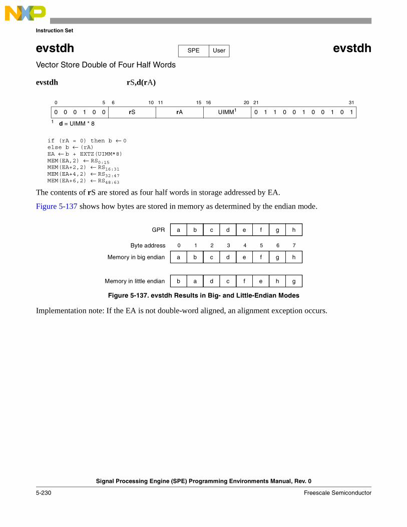
Instruction Set
Signal Processing Engine (SPE) Programming Environments Manual, Rev. 0
5-230 Freescale Semiconductor
evstdh evstdhVector Store Double of Four Half Words
evstdh rS,d(rA)
if (rA = 0) then b ← 0else b ← (rA)EA ← b + EXTZ(UIMM*8)MEM(EA,2) ← RS0:15MEM(EA+2,2) ← RS16:31MEM(EA+4,2) ← RS32:47MEM(EA+6,2) ← RS48:63
The contents of rS are stored as four half words in storage addressed by EA.
Figure 5-137 shows how bytes are stored in memory as determined by the endian mode.
Figure 5-137. evstdh Results in Big- and Little-Endian Modes
Implementation note: If the EA is not double-word aligned, an alignment exception occurs.
0 5 6 10 11 15 16 20 21 31
0 0 0 1 0 0 rS rA UIMM1
1 d = UIMM * 8
0 1 1 0 0 1 0 0 1 0 1
SPE User
c d e f ha b g
c d e f ha b g
d c f e gb a h
GPR
Memory in big endian
Memory in little endian
0 1 2 3 4 5 6 7Byte address
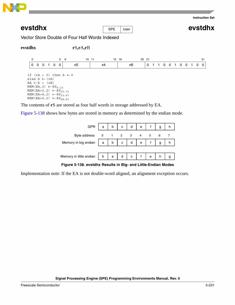
Instruction Set
Signal Processing Engine (SPE) Programming Environments Manual, Rev. 0
Freescale Semiconductor 5-231
evstdhx evstdhxVector Store Double of Four Half Words Indexed
evstdhx rS,rA,rB
if (rA = 0) then b ← 0else b ← (rA)EA ← b + (rB)MEM(EA,2) ← RS0:15MEM(EA+2,2) ← RS16:31MEM(EA+4,2) ← RS32:47MEM(EA+6,2) ← RS48:63
The contents of rS are stored as four half words in storage addressed by EA.
Figure 5-138 shows how bytes are stored in memory as determined by the endian mode.
Figure 5-138. evstdhx Results in Big- and Little-Endian Modes
Implementation note: If the EA is not double-word aligned, an alignment exception occurs.
0 5 6 10 11 15 16 20 21 31
0 0 0 1 0 0 rS rA rB 0 1 1 0 0 1 0 0 1 0 0
SPE User
c d e f ha b g
c d e f ha b g
d c f e gb a h
GPR
Memory in big endian
Memory in little endian
0 1 2 3 4 5 6 7Byte address
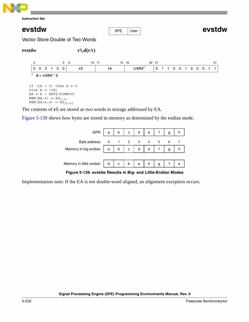
Instruction Set
Signal Processing Engine (SPE) Programming Environments Manual, Rev. 0
5-232 Freescale Semiconductor
evstdw evstdwVector Store Double of Two Words
evstdw rS,d(rA)
if (rA = 0) then b ← 0else b ← (rA)EA ← b + EXTZ(UIMM*8)MEM(EA,4) ← RS0:31MEM(EA+4,4) ← RS32:63
The contents of rS are stored as two words in storage addressed by EA.
Figure 5-139 shows how bytes are stored in memory as determined by the endian mode.
Figure 5-139. evstdw Results in Big- and Little-Endian Modes
Implementation note: If the EA is not double-word aligned, an alignment exception occurs.
0 5 6 10 11 15 16 20 21 31
0 0 0 1 0 0 rS rA UIMM1
1 d = UIMM * 8
0 1 1 0 0 1 0 0 0 1 1
SPE User
c d e f ha b g
0 1 2 3 4 5 6 7
c d e f ha b g
b a h g ed c f
GPR
Memory in big endian
Memory in little endian
Byte address
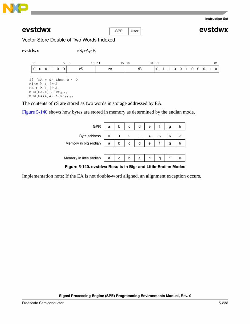
Instruction Set
Signal Processing Engine (SPE) Programming Environments Manual, Rev. 0
Freescale Semiconductor 5-233
evstdwx evstdwxVector Store Double of Two Words Indexed
evstdwx rS,rA,rB
if (rA = 0) then b ← 0else b ← (rA)EA ← b + (rB)MEM(EA,4) ← RS0:31MEM(EA+4,4) ← RS32:63
The contents of rS are stored as two words in storage addressed by EA.
Figure 5-140 shows how bytes are stored in memory as determined by the endian mode.
Figure 5-140. evstdwx Results in Big- and Little-Endian Modes
Implementation note: If the EA is not double-word aligned, an alignment exception occurs.
0 5 6 10 11 15 16 20 21 31
0 0 0 1 0 0 rS rA rB 0 1 1 0 0 1 0 0 0 1 0
SPE User
c d e f ha b g
0 1 2 3 4 5 6 7
c d e f ha b g
b a h g ed c f
GPR
Memory in big endian
Memory in little endian
Byte address
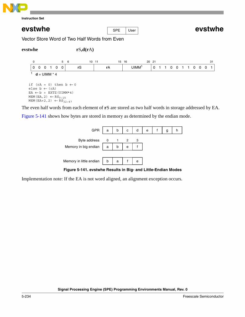
Instruction Set
Signal Processing Engine (SPE) Programming Environments Manual, Rev. 0
5-234 Freescale Semiconductor
evstwhe evstwheVector Store Word of Two Half Words from Even
evstwhe rS,d(rA)
if (rA = 0) then b ← 0else b ← (rA)EA ← b + EXTZ(UIMM*4)MEM(EA,2) ← RS0:15MEM(EA+2,2) ← RS32:47
The even half words from each element of rS are stored as two half words in storage addressed by EA.
Figure 5-141 shows how bytes are stored in memory as determined by the endian mode.
Figure 5-141. evstwhe Results in Big- and Little-Endian Modes
Implementation note: If the EA is not word aligned, an alignment exception occurs.
0 5 6 10 11 15 16 20 21 31
0 0 0 1 0 0 rS rA UIMM1
1 d = UIMM * 4
0 1 1 0 0 1 1 0 0 0 1
SPE User
c d e f ha b g
e fa b
f eb a
GPR
Memory in big endian
Memory in little endian
0 1 2 3Byte address
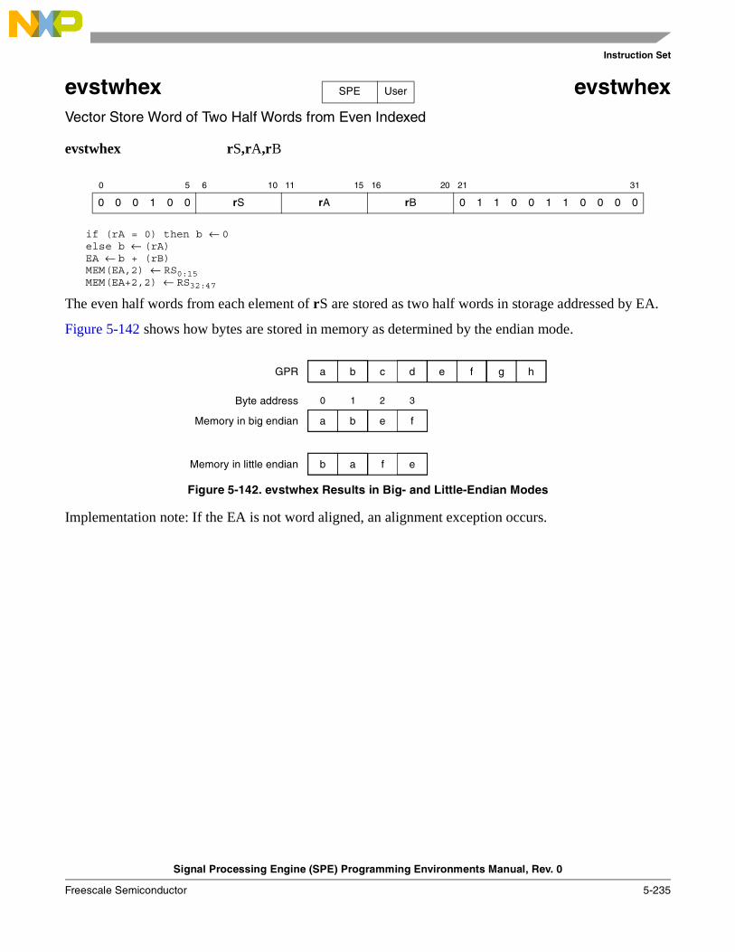
Instruction Set
Signal Processing Engine (SPE) Programming Environments Manual, Rev. 0
Freescale Semiconductor 5-235
evstwhex evstwhexVector Store Word of Two Half Words from Even Indexed
evstwhex rS,rA,rB
if (rA = 0) then b ← 0else b ← (rA)EA ← b + (rB)MEM(EA,2) ← RS0:15MEM(EA+2,2) ← RS32:47
The even half words from each element of rS are stored as two half words in storage addressed by EA.
Figure 5-142 shows how bytes are stored in memory as determined by the endian mode.
Figure 5-142. evstwhex Results in Big- and Little-Endian Modes
Implementation note: If the EA is not word aligned, an alignment exception occurs.
0 5 6 10 11 15 16 20 21 31
0 0 0 1 0 0 rS rA rB 0 1 1 0 0 1 1 0 0 0 0
SPE User
c d e f ha b g
e fa b
f eb a
GPR
Memory in big endian
Memory in little endian
0 1 2 3Byte address
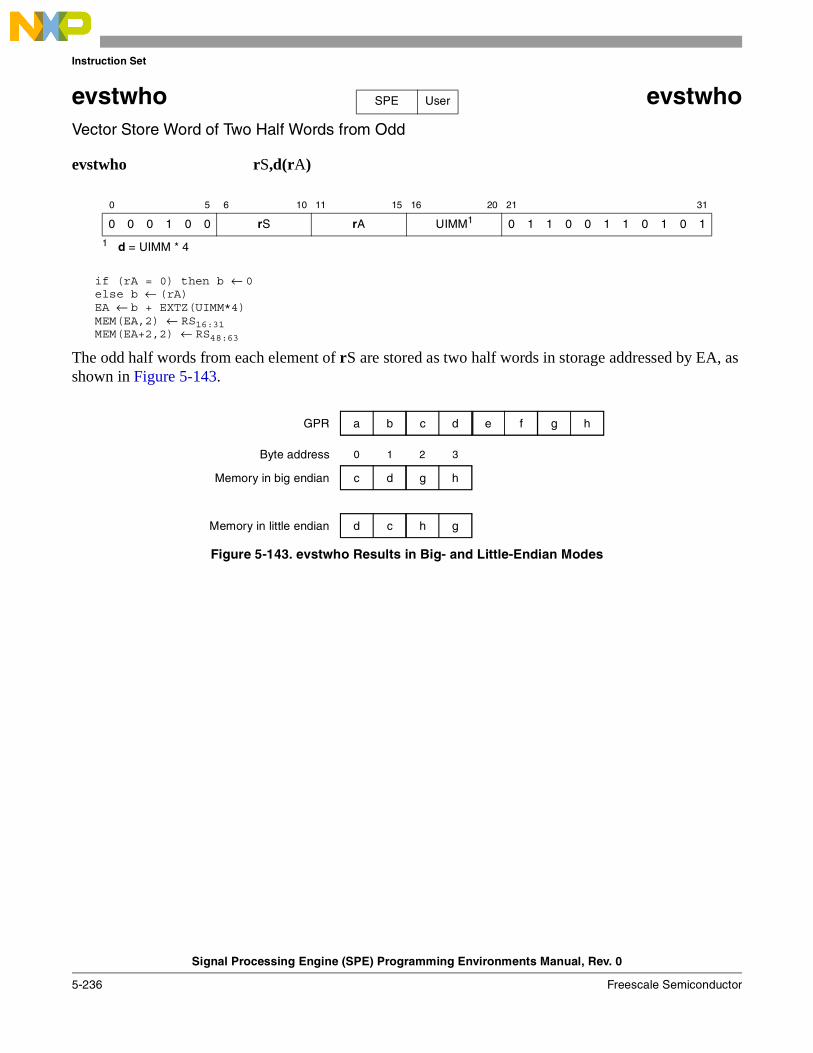
Instruction Set
Signal Processing Engine (SPE) Programming Environments Manual, Rev. 0
5-236 Freescale Semiconductor
evstwho evstwhoVector Store Word of Two Half Words from Odd
evstwho rS,d(rA)
if (rA = 0) then b ← 0else b ← (rA)EA ← b + EXTZ(UIMM*4)MEM(EA,2) ← RS16:31MEM(EA+2,2) ← RS48:63
The odd half words from each element of rS are stored as two half words in storage addressed by EA, as shown in Figure 5-143.
Figure 5-143. evstwho Results in Big- and Little-Endian Modes
0 5 6 10 11 15 16 20 21 31
0 0 0 1 0 0 rS rA UIMM1
1 d = UIMM * 4
0 1 1 0 0 1 1 0 1 0 1
SPE User
c d e f ha b g
0 1 2 3
g hc d
h gd c
GPR
Memory in big endian
Memory in little endian
Byte address
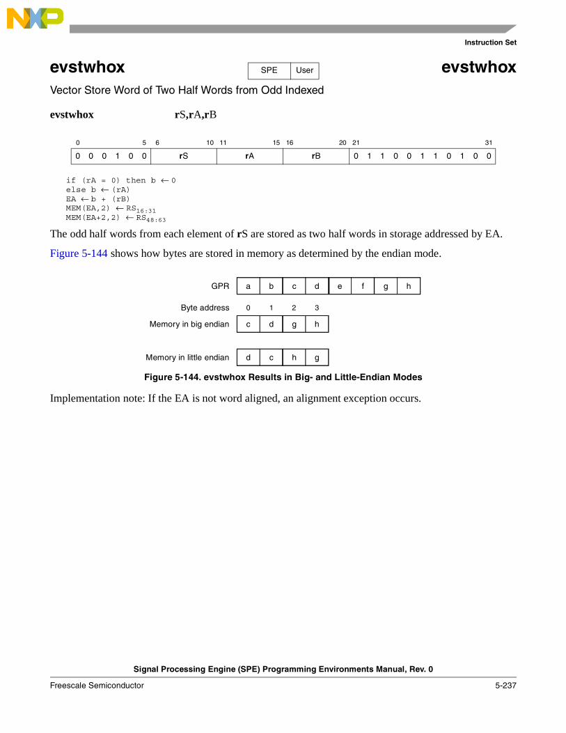
Instruction Set
Signal Processing Engine (SPE) Programming Environments Manual, Rev. 0
Freescale Semiconductor 5-237
evstwhox evstwhoxVector Store Word of Two Half Words from Odd Indexed
evstwhox rS,rA,rB
if (rA = 0) then b ← 0else b ← (rA)EA ← b + (rB)MEM(EA,2) ← RS16:31MEM(EA+2,2) ← RS48:63
The odd half words from each element of rS are stored as two half words in storage addressed by EA.
Figure 5-144 shows how bytes are stored in memory as determined by the endian mode.
Figure 5-144. evstwhox Results in Big- and Little-Endian Modes
Implementation note: If the EA is not word aligned, an alignment exception occurs.
0 5 6 10 11 15 16 20 21 31
0 0 0 1 0 0 rS rA rB 0 1 1 0 0 1 1 0 1 0 0
SPE User
c d e f ha b g
g hc d
h gd c
GPR
Memory in big endian
Memory in little endian
0 1 2 3Byte address
Instruction Set
Signal Processing Engine (SPE) Programming Environments Manual, Rev. 0
5-238 Freescale Semiconductor
evstwwe evstwweVector Store Word of Word from Even
evstwwe rS,d(rA)
if (rA = 0) then b ← 0else b ← (rA)EA ← b + EXTZ(UIMM*4)MEM(EA,4) ← RS0:31
The even word of rS is stored in storage addressed by EA.
Figure 5-145 shows how bytes are stored in memory as determined by the endian mode.
Figure 5-145. evstwwe Results in Big- and Little-Endian Modes
Implementation note: If the EA is not word aligned, an alignment exception occurs.
0 5 6 10 11 15 16 20 21 31
0 0 0 1 0 0 rS rA UIMM1
1 d = UIMM * 4
0 1 1 0 0 1 1 1 0 0 1
SPE User
c d e f ha b g
c da b
b ad c
GPR
Memory in big endian
Memory in little endian
0 1 2 3Byte address

Instruction Set
Signal Processing Engine (SPE) Programming Environments Manual, Rev. 0
Freescale Semiconductor 5-239
evstwwex evstwwexVector Store Word of Word from Even Indexed
evstwwex rS,rA,rB
if (rA = 0) then b ← 0else b ← (rA)EA ← b + (rB)MEM(EA,4) ← RS0:31
The even word of rS is stored in storage addressed by EA.
Figure 5-146 shows how bytes are stored in memory as determined by the endian mode.
Figure 5-146. evstwwex Results in Big- and Little-Endian Modes
Implementation note: If the EA is not word aligned, an alignment exception occurs.
0 5 6 10 11 15 16 20 21 31
0 0 0 1 0 0 rS rA rB 0 1 1 0 0 1 1 1 0 0 0
SPE User
c d e f ha b g
c da b
b ad c
GPR
Memory in big endian
Memory in little endian
0 1 2 3Byte address
Instruction Set
Signal Processing Engine (SPE) Programming Environments Manual, Rev. 0
5-240 Freescale Semiconductor
evstwwo evstwwoVector Store Word of Word from Odd
evstwwo rS,d(rA)
if (rA = 0) then b ← 0else b ← (rA)EA ← b + EXTZ(UIMM*4)MEM(EA,4) ← rS32:63
The odd word of rS is stored in storage addressed by EA.
Figure 5-147 shows how bytes are stored in memory as determined by the endian mode.
Figure 5-147. evstwwo Results in Big- and Little-Endian Modes
Implementation note: If the EA is not word aligned, an alignment exception occurs.
0 5 6 10 11 15 16 20 21 31
0 0 0 1 0 0 rS rA UIMM1
1 d = UIMM * 4
0 1 1 0 0 1 1 1 1 0 1
SPE User
c d e f ha b g
g he f
f eh g
GPR
Memory in big endian
Memory in little endian
0 1 2 3Byte address
Instruction Set
Signal Processing Engine (SPE) Programming Environments Manual, Rev. 0
Freescale Semiconductor 5-241
evstwwox evstwwoxVector Store Word of Word from Odd Indexed
evstwwox rS,rA,rB
if (rA = 0) then b ← 0else b ← (rA)EA ← b + (rB)MEM(EA,4) ← rS32:63
The odd word of rS is stored in storage addressed by EA.
Figure 5-148 shows how bytes are stored in memory as determined by the endian mode.
Figure 5-148. evstwwox Results in Big- and Little-Endian Modes
Implementation note: If the EA is not word aligned, an alignment exception occurs.
0 5 6 10 11 15 16 20 21 31
0 0 0 1 0 0 rS rA rB 0 1 1 0 0 1 1 1 1 0 0
SPE User
c d e f ha b g
g he f
f eh g
GPR
Memory in big endian
Memory in little endian
0 1 2 3Byte address
Instruction Set
Signal Processing Engine (SPE) Programming Environments Manual, Rev. 0
5-242 Freescale Semiconductor
evsubfsmiaaw evsubfsmiaawVector Subtract Signed, Modulo, Integer to Accumulator Word
evsubfsmiaaw rD,rA
// highrD0:31 ← ACC0:31 - rA0:31
// lowrD32:63 ← ACC32:63 - rA32:63
// update accumulatorACC0:63 ← rD0:63
Each word element in rA is subtracted from the corresponding element in the accumulator and the difference is placed into the corresponding rD word and into the accumulator, as shown in Figure 5-149.
Other registers altered: ACC
Figure 5-149. Vector Subtract Signed, Modulo, Integer toAccumulator Word (evsubfsmiaaw)
0 5 6 10 11 15 16 20 21 31
0 0 0 1 0 0 rD rA 0 0 0 0 0 1 0 0 1 1 0 0 1 0 1 1
SPE User
0 31 32 63
Accumulator
rA
– –
rD and Accumulator
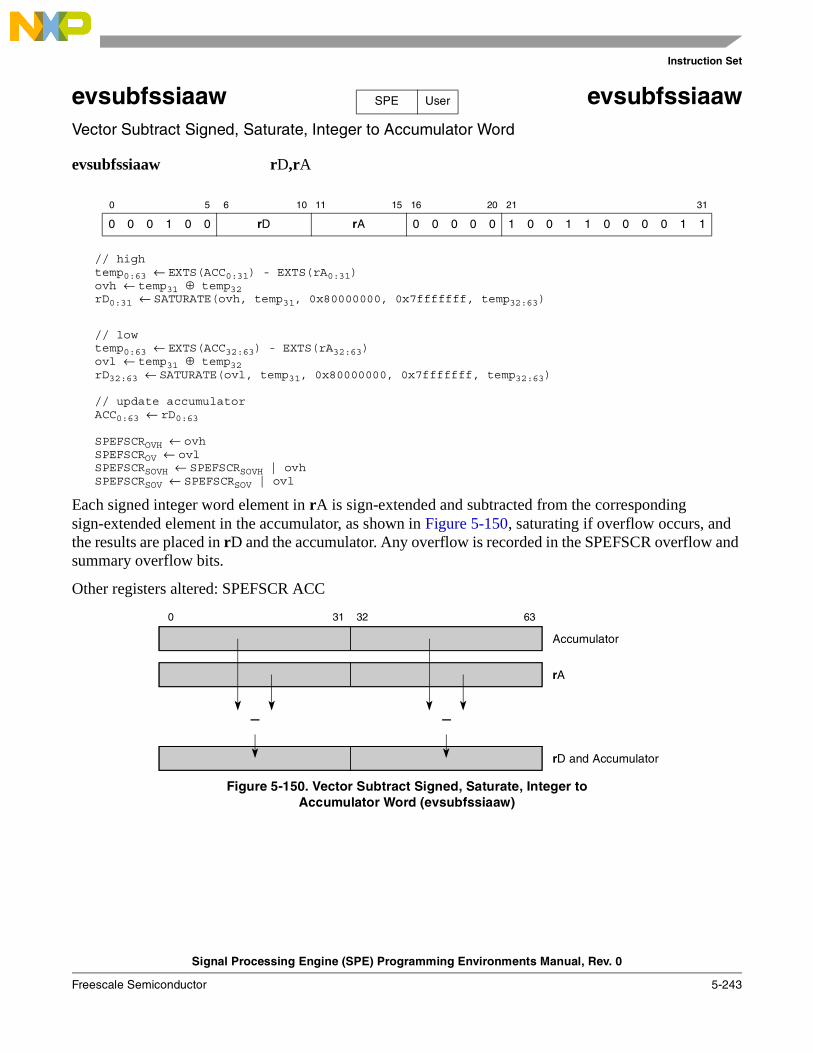
Instruction Set
Signal Processing Engine (SPE) Programming Environments Manual, Rev. 0
Freescale Semiconductor 5-243
evsubfssiaaw evsubfssiaawVector Subtract Signed, Saturate, Integer to Accumulator Word
evsubfssiaaw rD,rA
// hightemp0:63 ← EXTS(ACC0:31) - EXTS(rA0:31)ovh ← temp31 ⊕ temp32rD0:31 ← SATURATE(ovh, temp31, 0x80000000, 0x7fffffff, temp32:63)
// lowtemp0:63 ← EXTS(ACC32:63) - EXTS(rA32:63)ovl ← temp31 ⊕ temp32rD32:63 ← SATURATE(ovl, temp31, 0x80000000, 0x7fffffff, temp32:63)
// update accumulatorACC0:63 ← rD0:63
SPEFSCROVH ← ovhSPEFSCROV ← ovlSPEFSCRSOVH ← SPEFSCRSOVH | ovhSPEFSCRSOV ← SPEFSCRSOV | ovl
Each signed integer word element in rA is sign-extended and subtracted from the corresponding sign-extended element in the accumulator, as shown in Figure 5-150, saturating if overflow occurs, and the results are placed in rD and the accumulator. Any overflow is recorded in the SPEFSCR overflow and summary overflow bits.
Other registers altered: SPEFSCR ACC
Figure 5-150. Vector Subtract Signed, Saturate, Integer toAccumulator Word (evsubfssiaaw)
0 5 6 10 11 15 16 20 21 31
0 0 0 1 0 0 rD rA 0 0 0 0 0 1 0 0 1 1 0 0 0 0 1 1
SPE User
0 31 32 63
Accumulator
rA
– –
rD and Accumulator
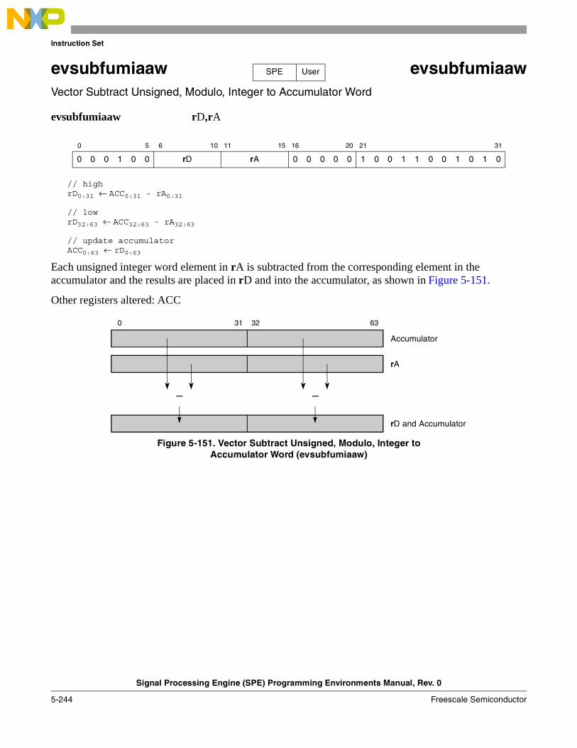
Instruction Set
Signal Processing Engine (SPE) Programming Environments Manual, Rev. 0
5-244 Freescale Semiconductor
evsubfumiaaw evsubfumiaawVector Subtract Unsigned, Modulo, Integer to Accumulator Word
evsubfumiaaw rD,rA
// highrD0:31 ← ACC0:31 - rA0:31
// lowrD32:63 ← ACC32:63 - rA32:63
// update accumulatorACC0:63 ← rD0:63
Each unsigned integer word element in rA is subtracted from the corresponding element in the accumulator and the results are placed in rD and into the accumulator, as shown in Figure 5-151.
Other registers altered: ACC
Figure 5-151. Vector Subtract Unsigned, Modulo, Integer toAccumulator Word (evsubfumiaaw)
0 5 6 10 11 15 16 20 21 31
0 0 0 1 0 0 rD rA 0 0 0 0 0 1 0 0 1 1 0 0 1 0 1 0
SPE User
0 31 32 63
Accumulator
rA
– –
rD and Accumulator
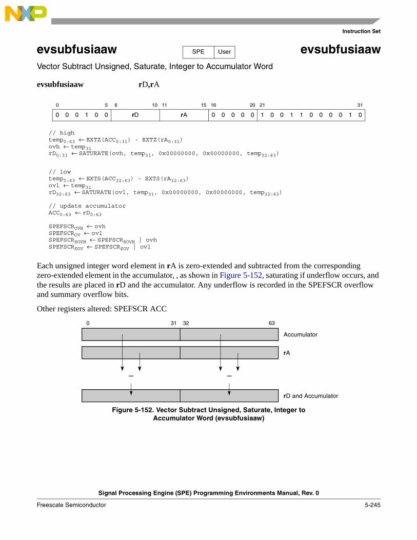
Instruction Set
Signal Processing Engine (SPE) Programming Environments Manual, Rev. 0
Freescale Semiconductor 5-245
evsubfusiaaw evsubfusiaawVector Subtract Unsigned, Saturate, Integer to Accumulator Word
evsubfusiaaw rD,rA
// hightemp0:63 ← EXTZ(ACC0:31) - EXTZ(rA0:31)ovh ← temp31 rD0:31 ← SATURATE(ovh, temp31, 0x00000000, 0x00000000, temp32:63)
// lowtemp0:63 ← EXTS(ACC32:63) - EXTS(rA32:63)ovl ← temp31 rD32:63 ← SATURATE(ovl, temp31, 0x00000000, 0x00000000, temp32:63)
// update accumulatorACC0:63 ← rD0:63
SPEFSCROVH ← ovhSPEFSCROV ← ovlSPEFSCRSOVH ← SPEFSCRSOVH | ovhSPEFSCRSOV ← SPEFSCRSOV | ovl
Each unsigned integer word element in rA is zero-extended and subtracted from the corresponding zero-extended element in the accumulator, , as shown in Figure 5-152, saturating if underflow occurs, and the results are placed in rD and the accumulator. Any underflow is recorded in the SPEFSCR overflow and summary overflow bits.
Other registers altered: SPEFSCR ACC
Figure 5-152. Vector Subtract Unsigned, Saturate, Integer toAccumulator Word (evsubfusiaaw)
0 5 6 10 11 15 16 20 21 31
0 0 0 1 0 0 rD rA 0 0 0 0 0 1 0 0 1 1 0 0 0 0 1 0
SPE User
0 31 32 63
Accumulator
rA
– –
rD and Accumulator
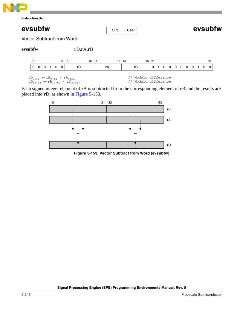
Instruction Set
Signal Processing Engine (SPE) Programming Environments Manual, Rev. 0
5-246 Freescale Semiconductor
evsubfw evsubfwVector Subtract from Word
evsubfw rD,rA,rB
rD0:31 ← rB0:31 - rA0:31 // Modulo differencerD32:63 ← rB32:63 - rA32:63 // Modulo difference
Each signed integer element of rA is subtracted from the corresponding element of rB and the results are placed into rD, as shown in Figure 5-153.
Figure 5-153. Vector Subtract from Word (evsubfw)
0 5 6 10 11 15 16 20 21 31
0 0 0 1 0 0 rD rA rB 0 1 0 0 0 0 0 0 1 0 0
SPE User
0 31 32 63
rB
rA
– –
rD
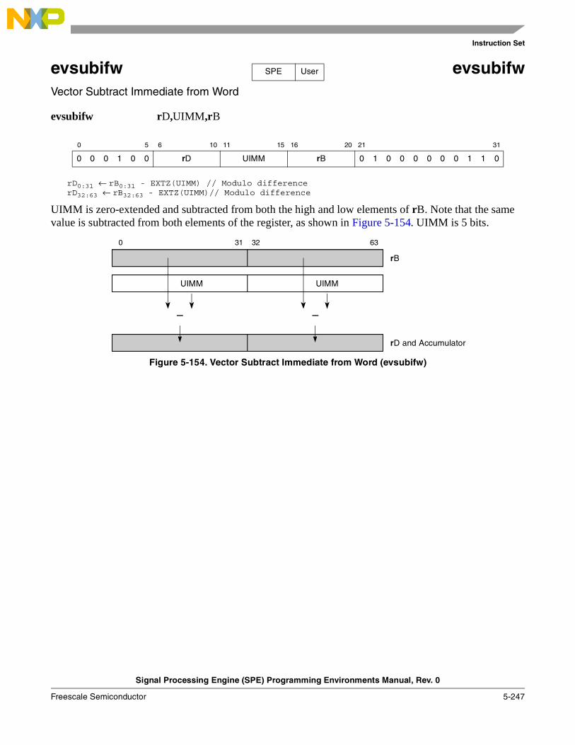
Instruction Set
Signal Processing Engine (SPE) Programming Environments Manual, Rev. 0
Freescale Semiconductor 5-247
evsubifw evsubifw Vector Subtract Immediate from Word
evsubifw rD,UIMM,rB
rD0:31 ← rB0:31 - EXTZ(UIMM) // Modulo differencerD32:63 ← rB32:63 - EXTZ(UIMM)// Modulo difference
UIMM is zero-extended and subtracted from both the high and low elements of rB. Note that the same value is subtracted from both elements of the register, as shown in Figure 5-154. UIMM is 5 bits.
Figure 5-154. Vector Subtract Immediate from Word (evsubifw)
0 5 6 10 11 15 16 20 21 31
0 0 0 1 0 0 rD UIMM rB 0 1 0 0 0 0 0 0 1 1 0
SPE User
0 31 32 63
rB
UIMM
– –
rD and Accumulator
UIMM
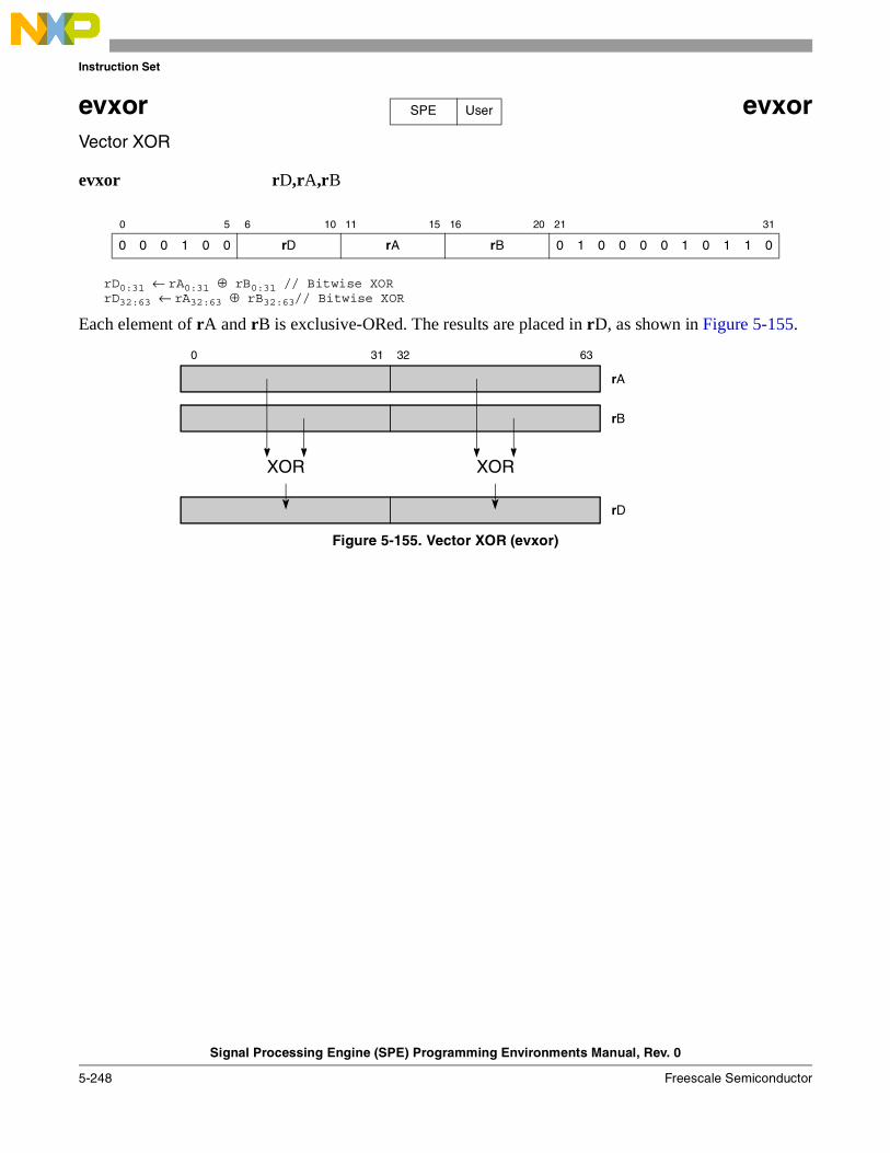
Instruction Set
Signal Processing Engine (SPE) Programming Environments Manual, Rev. 0
5-248 Freescale Semiconductor
evxor evxorVector XOR
evxor rD,rA,rB
rD0:31 ← rA0:31 ⊕ rB0:31 // Bitwise XORrD32:63 ← rA32:63 ⊕ rB32:63// Bitwise XOR
Each element of rA and rB is exclusive-ORed. The results are placed in rD, as shown in Figure 5-155.
Figure 5-155. Vector XOR (evxor)
0 5 6 10 11 15 16 20 21 31
0 0 0 1 0 0 rD rA rB 0 1 0 0 0 0 1 0 1 1 0
SPE User
0 31 32 63
rA
rB
XOR XOR
rD

Embedded Floating-Point Results Summary
Signal Processing Engine (SPE) Programming Environments Manual, Rev. 0
Freescale Semiconductor A-1
Appendix A Embedded Floating-Point Results SummaryTable A-1 through Table A-8 summarize the results of various types of embedded floating-point operations on various combinations of input operands. Flag settings are performed on appropriate element flags. For all the tables the following annotation and general rules apply:
• * denotes that this status flag is set based on the results of the calculation.
• _Calc_ denotes that the result is updated with the results of the computation.
• max denotes the maximum normalized number with the sign set to the computation [sign(operand A) XOR sign(operand B)].
• amax denotes the maximum normalized number with the sign set to the sign of Operand A.
• bmax denotes the maximum normalized number with the sign set to the sign of Operand B.
• pmax denotes the maximum normalized positive number. The encoding for single-precision is: 0x7F7FFFFF. The encoding for double-precision is: 0x7FEFFFFF_FFFFFFFF.
• nmax denotes the maximum normalized negative number. The encoding for single-precision is: 0xFF7FFFFF. The encoding for double-precision is: 0xFFEFFFFF_FFFFFFFF.
• pmin denotes the minimum normalized positive number. The encoding for single-precision is: 0x00800000. The encoding for double-precision is: 0x00100000_00000000.
• nmin denotes the minimum normalized negative number. The encoding for single-precision is: 0x80800000. The encoding for double-precision is: 0x80100000_00000000.
• Calculations that overflow or underflow saturate. Overflow for operations that have a floating-point result force the result to max. Underflow for operations that have a floating-point result force the result to zero. Overflow for operations that have a signed integer result force the result to 0x7FFFFFFF (positive) or 0x80000000 (negative). Overflow for operations that have an unsigned integer result force the result to 0xFFFFFFFF (positive) or 0x00000000 (negative).
• 1 (superscript) denotes that the sign of the result is positive when the sign of Operand A and the sign of Operand B are different, for all rounding modes except round to minus infinity, where the sign of the result is then negative.
• 2 (superscript) denotes that the sign of the result is positive when the sign of Operand A and the sign of Operand B are the same, for all rounding modes except round to minus infinity, where the sign of the result is then negative.
• 3 (superscript) denotes that the sign for any multiply or divide is always the result of the operation [sign(Operand A) XOR sign(Operand B)].
• 4 (superscript) denotes that if an overflow is detected, the result may be saturated.
Table A-1. Embedded Floating-Point Results Summary—Add, Sub, Mul, Div
Operation Operand A Operand B Result FINV FOVF FUNF FDBZ FINX
Add
Add ∞ ∞ amax 1 0 0 0 0
Add ∞ NaN amax 1 0 0 0 0
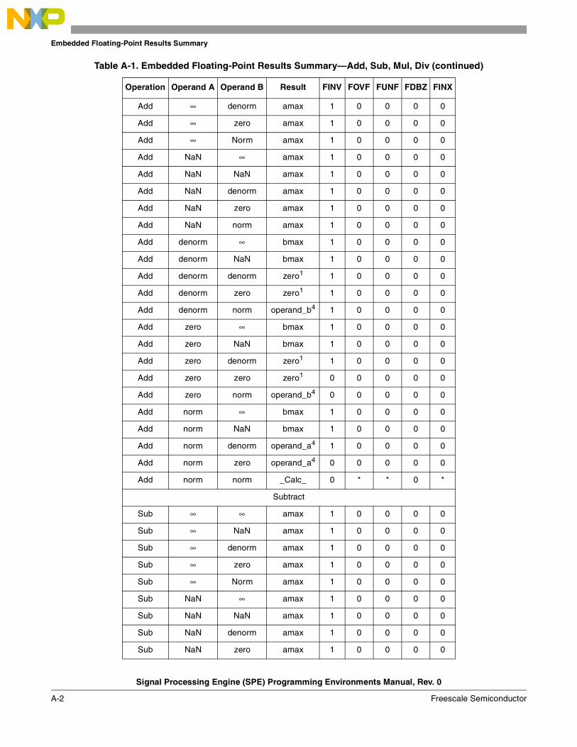
Embedded Floating-Point Results Summary
Signal Processing Engine (SPE) Programming Environments Manual, Rev. 0
A-2 Freescale Semiconductor
Add ∞ denorm amax 1 0 0 0 0
Add ∞ zero amax 1 0 0 0 0
Add ∞ Norm amax 1 0 0 0 0
Add NaN ∞ amax 1 0 0 0 0
Add NaN NaN amax 1 0 0 0 0
Add NaN denorm amax 1 0 0 0 0
Add NaN zero amax 1 0 0 0 0
Add NaN norm amax 1 0 0 0 0
Add denorm ∞ bmax 1 0 0 0 0
Add denorm NaN bmax 1 0 0 0 0
Add denorm denorm zero1 1 0 0 0 0
Add denorm zero zero1 1 0 0 0 0
Add denorm norm operand_b4 1 0 0 0 0
Add zero ∞ bmax 1 0 0 0 0
Add zero NaN bmax 1 0 0 0 0
Add zero denorm zero1 1 0 0 0 0
Add zero zero zero1 0 0 0 0 0
Add zero norm operand_b4 0 0 0 0 0
Add norm ∞ bmax 1 0 0 0 0
Add norm NaN bmax 1 0 0 0 0
Add norm denorm operand_a4 1 0 0 0 0
Add norm zero operand_a4 0 0 0 0 0
Add norm norm _Calc_ 0 * * 0 *
Subtract
Sub ∞ ∞ amax 1 0 0 0 0
Sub ∞ NaN amax 1 0 0 0 0
Sub ∞ denorm amax 1 0 0 0 0
Sub ∞ zero amax 1 0 0 0 0
Sub ∞ Norm amax 1 0 0 0 0
Sub NaN ∞ amax 1 0 0 0 0
Sub NaN NaN amax 1 0 0 0 0
Sub NaN denorm amax 1 0 0 0 0
Sub NaN zero amax 1 0 0 0 0
Table A-1. Embedded Floating-Point Results Summary—Add, Sub, Mul, Div (continued)
Operation Operand A Operand B Result FINV FOVF FUNF FDBZ FINX
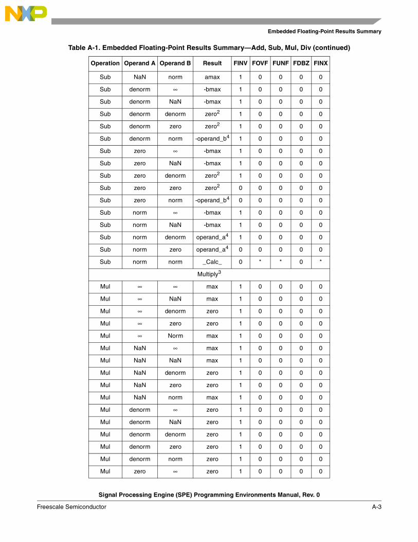
Embedded Floating-Point Results Summary
Signal Processing Engine (SPE) Programming Environments Manual, Rev. 0
Freescale Semiconductor A-3
Sub NaN norm amax 1 0 0 0 0
Sub denorm ∞ -bmax 1 0 0 0 0
Sub denorm NaN -bmax 1 0 0 0 0
Sub denorm denorm zero2 1 0 0 0 0
Sub denorm zero zero2 1 0 0 0 0
Sub denorm norm -operand_b4 1 0 0 0 0
Sub zero ∞ -bmax 1 0 0 0 0
Sub zero NaN -bmax 1 0 0 0 0
Sub zero denorm zero2 1 0 0 0 0
Sub zero zero zero2 0 0 0 0 0
Sub zero norm -operand_b4 0 0 0 0 0
Sub norm ∞ -bmax 1 0 0 0 0
Sub norm NaN -bmax 1 0 0 0 0
Sub norm denorm operand_a4 1 0 0 0 0
Sub norm zero operand_a4 0 0 0 0 0
Sub norm norm _Calc_ 0 * * 0 *
Multiply3
Mul ∞ ∞ max 1 0 0 0 0
Mul ∞ NaN max 1 0 0 0 0
Mul ∞ denorm zero 1 0 0 0 0
Mul ∞ zero zero 1 0 0 0 0
Mul ∞ Norm max 1 0 0 0 0
Mul NaN ∞ max 1 0 0 0 0
Mul NaN NaN max 1 0 0 0 0
Mul NaN denorm zero 1 0 0 0 0
Mul NaN zero zero 1 0 0 0 0
Mul NaN norm max 1 0 0 0 0
Mul denorm ∞ zero 1 0 0 0 0
Mul denorm NaN zero 1 0 0 0 0
Mul denorm denorm zero 1 0 0 0 0
Mul denorm zero zero 1 0 0 0 0
Mul denorm norm zero 1 0 0 0 0
Mul zero ∞ zero 1 0 0 0 0
Table A-1. Embedded Floating-Point Results Summary—Add, Sub, Mul, Div (continued)
Operation Operand A Operand B Result FINV FOVF FUNF FDBZ FINX
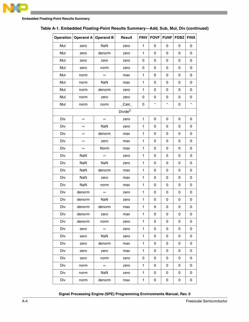
Embedded Floating-Point Results Summary
Signal Processing Engine (SPE) Programming Environments Manual, Rev. 0
A-4 Freescale Semiconductor
Mul zero NaN zero 1 0 0 0 0
Mul zero denorm zero 1 0 0 0 0
Mul zero zero zero 0 0 0 0 0
Mul zero norm zero 0 0 0 0 0
Mul norm ∞ max 1 0 0 0 0
Mul norm NaN max 1 0 0 0 0
Mul norm denorm zero 1 0 0 0 0
Mul norm zero zero 0 0 0 0 0
Mul norm norm _Calc_ 0 * * 0 *
Divide3
Div ∞ ∞ zero 1 0 0 0 0
Div ∞ NaN zero 1 0 0 0 0
Div ∞ denorm max 1 0 0 0 0
Div ∞ zero max 1 0 0 0 0
Div ∞ Norm max 1 0 0 0 0
Div NaN ∞ zero 1 0 0 0 0
Div NaN NaN zero 1 0 0 0 0
Div NaN denorm max 1 0 0 0 0
Div NaN zero max 1 0 0 0 0
Div NaN norm max 1 0 0 0 0
Div denorm ∞ zero 1 0 0 0 0
Div denorm NaN zero 1 0 0 0 0
Div denorm denorm max 1 0 0 0 0
Div denorm zero max 1 0 0 0 0
Div denorm norm zero 1 0 0 0 0
Div zero ∞ zero 1 0 0 0 0
Div zero NaN zero 1 0 0 0 0
Div zero denorm max 1 0 0 0 0
Div zero zero max 1 0 0 0 0
Div zero norm zero 0 0 0 0 0
Div norm ∞ zero 1 0 0 0 0
Div norm NaN zero 1 0 0 0 0
Div norm denorm max 1 0 0 0 0
Table A-1. Embedded Floating-Point Results Summary—Add, Sub, Mul, Div (continued)
Operation Operand A Operand B Result FINV FOVF FUNF FDBZ FINX
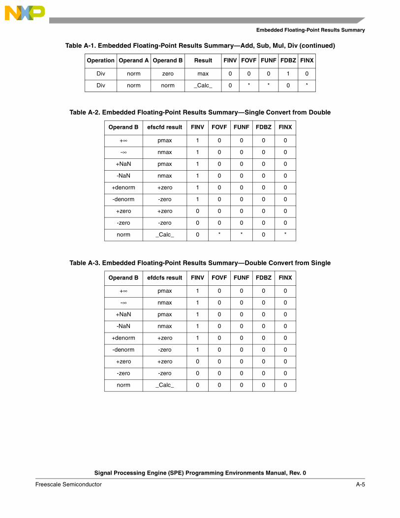
Embedded Floating-Point Results Summary
Signal Processing Engine (SPE) Programming Environments Manual, Rev. 0
Freescale Semiconductor A-5
Div norm zero max 0 0 0 1 0
Div norm norm _Calc_ 0 * * 0 *
Table A-2. Embedded Floating-Point Results Summary—Single Convert from Double
Operand B efscfd result FINV FOVF FUNF FDBZ FINX
+∞ pmax 1 0 0 0 0
-∞ nmax 1 0 0 0 0
+NaN pmax 1 0 0 0 0
-NaN nmax 1 0 0 0 0
+denorm +zero 1 0 0 0 0
-denorm -zero 1 0 0 0 0
+zero +zero 0 0 0 0 0
-zero -zero 0 0 0 0 0
norm _Calc_ 0 * * 0 *
Table A-3. Embedded Floating-Point Results Summary—Double Convert from Single
Operand B efdcfs result FINV FOVF FUNF FDBZ FINX
+∞ pmax 1 0 0 0 0
-∞ nmax 1 0 0 0 0
+NaN pmax 1 0 0 0 0
-NaN nmax 1 0 0 0 0
+denorm +zero 1 0 0 0 0
-denorm -zero 1 0 0 0 0
+zero +zero 0 0 0 0 0
-zero -zero 0 0 0 0 0
norm _Calc_ 0 0 0 0 0
Table A-1. Embedded Floating-Point Results Summary—Add, Sub, Mul, Div (continued)
Operation Operand A Operand B Result FINV FOVF FUNF FDBZ FINX

Embedded Floating-Point Results Summary
Signal Processing Engine (SPE) Programming Environments Manual, Rev. 0
A-6 Freescale Semiconductor
Table A-4. Embedded Floating-Point Results Summary—Convert to Unsigned
Operand B Integer Result:ctui[d][z] Fractional Result: ctuf FINV FOVF FUNF FDBZ FINX
+∞ 0xFFFF_FFFF 0xFFFF_FFFF_FFFF_FFFF
0x7FFF_FFFF 1 0 0 0 0
-∞ 0 0 1 0 0 0 0
+NaN 0 0 1 0 0 0 0
-NaN 0 0 1 0 0 0 0
denorm 0 0 1 0 0 0 0
zero 0 0 0 0 0 0 0
+norm _Calc_ _Calc_ * 0 0 0 *
-norm _Calc_ _Calc_ * 0 0 0 *
Table A-5. Embedded Floating-Point Results Summary—Convert to Signed
Operand BInteger Result
ctsi[d][z]Fractional Result
ctsfFINV FOVF FUNF FDBZ FINX
+∞ 0x7FFF_FFFF0x7FFF_FFFF_FFFF_FFFF
0x7FFF_FFFF 1 0 0 0 0
-∞ 0x8000_00000x8000_0000_0000_0000
0x8000_0000 1 0 0 0 0
+NaN 0 0 1 0 0 0 0
-NaN 0 0 1 0 0 0 0
denorm 0 0 1 0 0 0 0
zero 0 0 0 0 0 0 0
+norm _Calc_ _Calc_ * 0 0 0 *
-norm _Calc_ _Calc_ * 0 0 0 *
Table A-6. Results Summary—Convert from Unsigned
Operand B Integer Source: cfui Fractional Source: cfuf FINV FOVF FUNF FDBZ FINX
zero zero zero 0 0 0 0 0
norm _Calc_ _Calc_ 0 0 0 0 *

Embedded Floating-Point Results Summary
Signal Processing Engine (SPE) Programming Environments Manual, Rev. 0
Freescale Semiconductor A-7
Table A-7. Embedded Floating-Point Results Summary—Convert from Signed
Operand B Integer Source: cfsi Fractional Source: cfsf FINV FOVF FUNF FDBZ FINX
zero zero zero 0 0 0 0 0
norm _Calc_ _Calc_ 0 0 0 0 *
Table A-8. Embedded Floating-Point Results Summary—*abs, *nabs, *neg
Operand A *abs *nabs *neg FINV FOVF FUNF FDBZ FINX
+∞ pmax | +∞ nmax | -∞ -amax | -∞ 1 0 0 0 0
-∞ pmax | +∞ nmax | -∞ -amax | +∞ 1 0 0 0 0
+NaN pmax | NaN nmax | -NaN -amax | -NaN 1 0 0 0 0
-NaN pmax | NaN nmax | -NaN -amax | +NaN 1 0 0 0 0
+denorm +zero | +denorm -zero | -denorm -zero | -denorm 1 0 0 0 0
-denorm +zero | +denorm -zero | -denorm +zero | +denorm 1 0 0 0 0
+zero +zero -zero -zero 0 0 0 0 0
-zero +zero -zero +zero 0 0 0 0 0
+norm +norm -norm -norm 0 0 0 0 0
-norm +norm -norm +norm 0 0 0 0 0

Embedded Floating-Point Results Summary
Signal Processing Engine (SPE) Programming Environments Manual, Rev. 0
A-8 Freescale Semiconductor
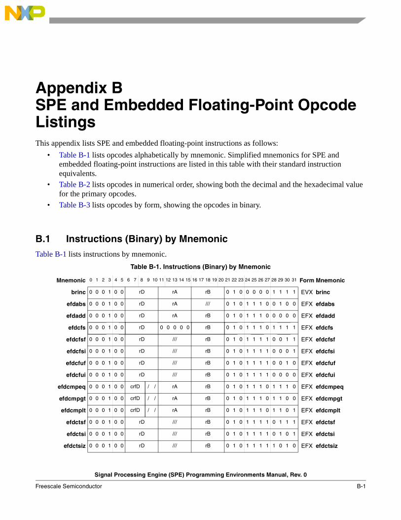
Signal Processing Engine (SPE) Programming Environments Manual, Rev. 0
Freescale Semiconductor B-1
Appendix BSPE and Embedded Floating-Point Opcode ListingsThis appendix lists SPE and embedded floating-point instructions as follows:
• Table B-1 lists opcodes alphabetically by mnemonic. Simplified mnemonics for SPE and embedded floating-point instructions are listed in this table with their standard instruction equivalents.
• Table B-2 lists opcodes in numerical order, showing both the decimal and the hexadecimal value for the primary opcodes.
• Table B-3 lists opcodes by form, showing the opcodes in binary.
B.1 Instructions (Binary) by MnemonicTable B-1 lists instructions by mnemonic.
Table B-1. Instructions (Binary) by Mnemonic
Mnemonic 0 1 2 3 4 5 6 7 8 9 10 11 12 13 14 15 16 17 18 19 20 21 22 23 24 25 26 27 28 29 30 31 Form Mnemonic
brinc 0 0 0 1 0 0 rD rA rB 0 1 0 0 0 0 0 1 1 1 1 EVX brinc
efdabs 0 0 0 1 0 0 rD rA /// 0 1 0 1 1 1 0 0 1 0 0 EFX efdabs
efdadd 0 0 0 1 0 0 rD rA rB 0 1 0 1 1 1 0 0 0 0 0 EFX efdadd
efdcfs 0 0 0 1 0 0 rD 0 0 0 0 0 rB 0 1 0 1 1 1 0 1 1 1 1 EFX efdcfs
efdcfsf 0 0 0 1 0 0 rD /// rB 0 1 0 1 1 1 1 0 0 1 1 EFX efdcfsf
efdcfsi 0 0 0 1 0 0 rD /// rB 0 1 0 1 1 1 1 0 0 0 1 EFX efdcfsi
efdcfuf 0 0 0 1 0 0 rD /// rB 0 1 0 1 1 1 1 0 0 1 0 EFX efdcfuf
efdcfui 0 0 0 1 0 0 rD /// rB 0 1 0 1 1 1 1 0 0 0 0 EFX efdcfui
efdcmpeq 0 0 0 1 0 0 crfD / / rA rB 0 1 0 1 1 1 0 1 1 1 0 EFX efdcmpeq
efdcmpgt 0 0 0 1 0 0 crfD / / rA rB 0 1 0 1 1 1 0 1 1 0 0 EFX efdcmpgt
efdcmplt 0 0 0 1 0 0 crfD / / rA rB 0 1 0 1 1 1 0 1 1 0 1 EFX efdcmplt
efdctsf 0 0 0 1 0 0 rD /// rB 0 1 0 1 1 1 1 0 1 1 1 EFX efdctsf
efdctsi 0 0 0 1 0 0 rD /// rB 0 1 0 1 1 1 1 0 1 0 1 EFX efdctsi
efdctsiz 0 0 0 1 0 0 rD /// rB 0 1 0 1 1 1 1 1 0 1 0 EFX efdctsiz
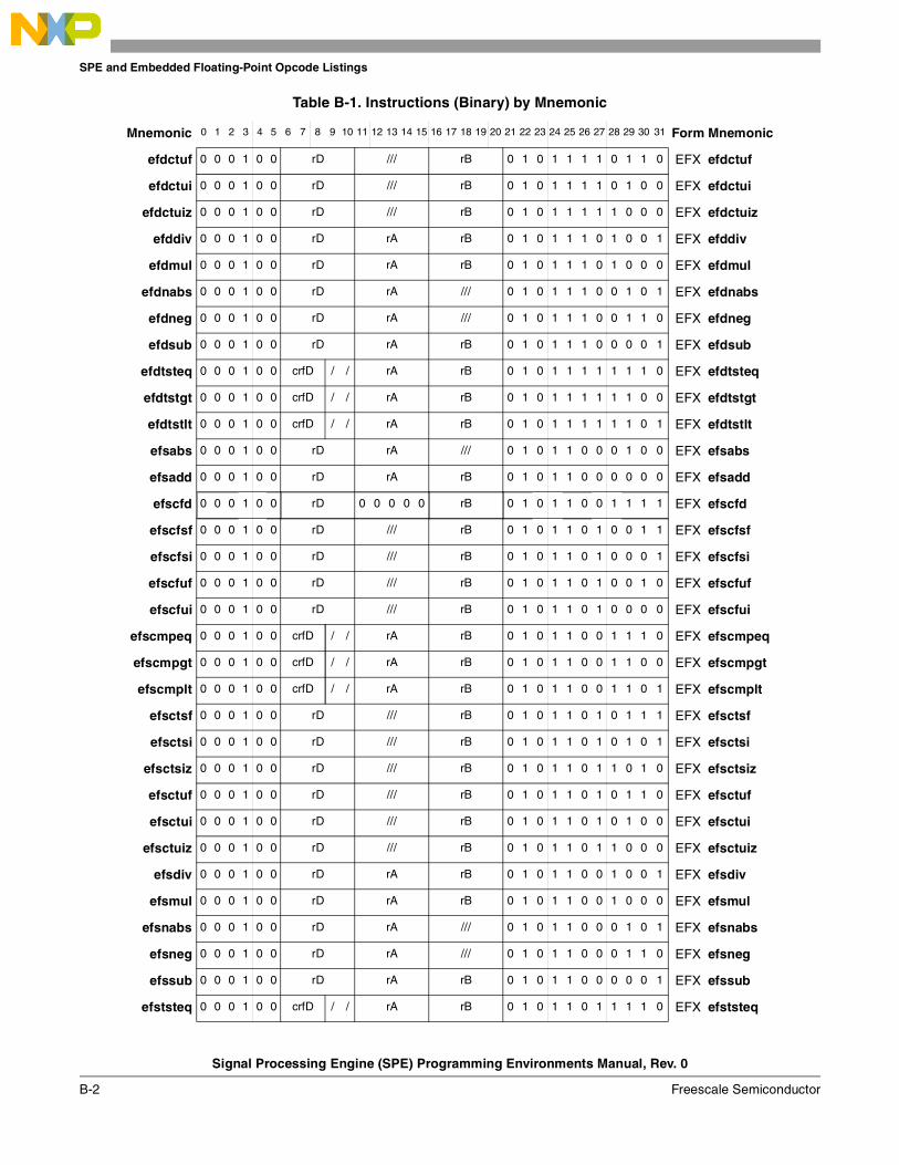
SPE and Embedded Floating-Point Opcode Listings
Signal Processing Engine (SPE) Programming Environments Manual, Rev. 0
B-2 Freescale Semiconductor
efdctuf 0 0 0 1 0 0 rD /// rB 0 1 0 1 1 1 1 0 1 1 0 EFX efdctuf
efdctui 0 0 0 1 0 0 rD /// rB 0 1 0 1 1 1 1 0 1 0 0 EFX efdctui
efdctuiz 0 0 0 1 0 0 rD /// rB 0 1 0 1 1 1 1 1 0 0 0 EFX efdctuiz
efddiv 0 0 0 1 0 0 rD rA rB 0 1 0 1 1 1 0 1 0 0 1 EFX efddiv
efdmul 0 0 0 1 0 0 rD rA rB 0 1 0 1 1 1 0 1 0 0 0 EFX efdmul
efdnabs 0 0 0 1 0 0 rD rA /// 0 1 0 1 1 1 0 0 1 0 1 EFX efdnabs
efdneg 0 0 0 1 0 0 rD rA /// 0 1 0 1 1 1 0 0 1 1 0 EFX efdneg
efdsub 0 0 0 1 0 0 rD rA rB 0 1 0 1 1 1 0 0 0 0 1 EFX efdsub
efdtsteq 0 0 0 1 0 0 crfD / / rA rB 0 1 0 1 1 1 1 1 1 1 0 EFX efdtsteq
efdtstgt 0 0 0 1 0 0 crfD / / rA rB 0 1 0 1 1 1 1 1 1 0 0 EFX efdtstgt
efdtstlt 0 0 0 1 0 0 crfD / / rA rB 0 1 0 1 1 1 1 1 1 0 1 EFX efdtstlt
efsabs 0 0 0 1 0 0 rD rA /// 0 1 0 1 1 0 0 0 1 0 0 EFX efsabs
efsadd 0 0 0 1 0 0 rD rA rB 0 1 0 1 1 0 0 0 0 0 0 EFX efsadd
efscfd 0 0 0 1 0 0 rD 0 0 0 0 0 rB 0 1 0 1 1 0 0 1 1 1 1 EFX efscfd
efscfsf 0 0 0 1 0 0 rD /// rB 0 1 0 1 1 0 1 0 0 1 1 EFX efscfsf
efscfsi 0 0 0 1 0 0 rD /// rB 0 1 0 1 1 0 1 0 0 0 1 EFX efscfsi
efscfuf 0 0 0 1 0 0 rD /// rB 0 1 0 1 1 0 1 0 0 1 0 EFX efscfuf
efscfui 0 0 0 1 0 0 rD /// rB 0 1 0 1 1 0 1 0 0 0 0 EFX efscfui
efscmpeq 0 0 0 1 0 0 crfD / / rA rB 0 1 0 1 1 0 0 1 1 1 0 EFX efscmpeq
efscmpgt 0 0 0 1 0 0 crfD / / rA rB 0 1 0 1 1 0 0 1 1 0 0 EFX efscmpgt
efscmplt 0 0 0 1 0 0 crfD / / rA rB 0 1 0 1 1 0 0 1 1 0 1 EFX efscmplt
efsctsf 0 0 0 1 0 0 rD /// rB 0 1 0 1 1 0 1 0 1 1 1 EFX efsctsf
efsctsi 0 0 0 1 0 0 rD /// rB 0 1 0 1 1 0 1 0 1 0 1 EFX efsctsi
efsctsiz 0 0 0 1 0 0 rD /// rB 0 1 0 1 1 0 1 1 0 1 0 EFX efsctsiz
efsctuf 0 0 0 1 0 0 rD /// rB 0 1 0 1 1 0 1 0 1 1 0 EFX efsctuf
efsctui 0 0 0 1 0 0 rD /// rB 0 1 0 1 1 0 1 0 1 0 0 EFX efsctui
efsctuiz 0 0 0 1 0 0 rD /// rB 0 1 0 1 1 0 1 1 0 0 0 EFX efsctuiz
efsdiv 0 0 0 1 0 0 rD rA rB 0 1 0 1 1 0 0 1 0 0 1 EFX efsdiv
efsmul 0 0 0 1 0 0 rD rA rB 0 1 0 1 1 0 0 1 0 0 0 EFX efsmul
efsnabs 0 0 0 1 0 0 rD rA /// 0 1 0 1 1 0 0 0 1 0 1 EFX efsnabs
efsneg 0 0 0 1 0 0 rD rA /// 0 1 0 1 1 0 0 0 1 1 0 EFX efsneg
efssub 0 0 0 1 0 0 rD rA rB 0 1 0 1 1 0 0 0 0 0 1 EFX efssub
efststeq 0 0 0 1 0 0 crfD / / rA rB 0 1 0 1 1 0 1 1 1 1 0 EFX efststeq
Table B-1. Instructions (Binary) by Mnemonic
Mnemonic 0 1 2 3 4 5 6 7 8 9 10 11 12 13 14 15 16 17 18 19 20 21 22 23 24 25 26 27 28 29 30 31 Form Mnemonic
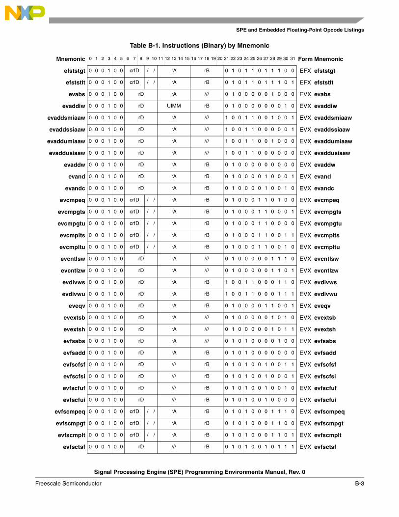
SPE and Embedded Floating-Point Opcode Listings
Signal Processing Engine (SPE) Programming Environments Manual, Rev. 0
Freescale Semiconductor B-3
efststgt 0 0 0 1 0 0 crfD / / rA rB 0 1 0 1 1 0 1 1 1 0 0 EFX efststgt
efststlt 0 0 0 1 0 0 crfD / / rA rB 0 1 0 1 1 0 1 1 1 0 1 EFX efststlt
evabs 0 0 0 1 0 0 rD rA /// 0 1 0 0 0 0 0 1 0 0 0 EVX evabs
evaddiw 0 0 0 1 0 0 rD UIMM rB 0 1 0 0 0 0 0 0 0 1 0 EVX evaddiw
evaddsmiaaw 0 0 0 1 0 0 rD rA /// 1 0 0 1 1 0 0 1 0 0 1 EVX evaddsmiaaw
evaddssiaaw 0 0 0 1 0 0 rD rA /// 1 0 0 1 1 0 0 0 0 0 1 EVX evaddssiaaw
evaddumiaaw 0 0 0 1 0 0 rD rA /// 1 0 0 1 1 0 0 1 0 0 0 EVX evaddumiaaw
evaddusiaaw 0 0 0 1 0 0 rD rA /// 1 0 0 1 1 0 0 0 0 0 0 EVX evaddusiaaw
evaddw 0 0 0 1 0 0 rD rA rB 0 1 0 0 0 0 0 0 0 0 0 EVX evaddw
evand 0 0 0 1 0 0 rD rA rB 0 1 0 0 0 0 1 0 0 0 1 EVX evand
evandc 0 0 0 1 0 0 rD rA rB 0 1 0 0 0 0 1 0 0 1 0 EVX evandc
evcmpeq 0 0 0 1 0 0 crfD / / rA rB 0 1 0 0 0 1 1 0 1 0 0 EVX evcmpeq
evcmpgts 0 0 0 1 0 0 crfD / / rA rB 0 1 0 0 0 1 1 0 0 0 1 EVX evcmpgts
evcmpgtu 0 0 0 1 0 0 crfD / / rA rB 0 1 0 0 0 1 1 0 0 0 0 EVX evcmpgtu
evcmplts 0 0 0 1 0 0 crfD / / rA rB 0 1 0 0 0 1 1 0 0 1 1 EVX evcmplts
evcmpltu 0 0 0 1 0 0 crfD / / rA rB 0 1 0 0 0 1 1 0 0 1 0 EVX evcmpltu
evcntlsw 0 0 0 1 0 0 rD rA /// 0 1 0 0 0 0 0 1 1 1 0 EVX evcntlsw
evcntlzw 0 0 0 1 0 0 rD rA /// 0 1 0 0 0 0 0 1 1 0 1 EVX evcntlzw
evdivws 0 0 0 1 0 0 rD rA rB 1 0 0 1 1 0 0 0 1 1 0 EVX evdivws
evdivwu 0 0 0 1 0 0 rD rA rB 1 0 0 1 1 0 0 0 1 1 1 EVX evdivwu
eveqv 0 0 0 1 0 0 rD rA rB 0 1 0 0 0 0 1 1 0 0 1 EVX eveqv
evextsb 0 0 0 1 0 0 rD rA /// 0 1 0 0 0 0 0 1 0 1 0 EVX evextsb
evextsh 0 0 0 1 0 0 rD rA /// 0 1 0 0 0 0 0 1 0 1 1 EVX evextsh
evfsabs 0 0 0 1 0 0 rD rA /// 0 1 0 1 0 0 0 0 1 0 0 EVX evfsabs
evfsadd 0 0 0 1 0 0 rD rA rB 0 1 0 1 0 0 0 0 0 0 0 EVX evfsadd
evfscfsf 0 0 0 1 0 0 rD /// rB 0 1 0 1 0 0 1 0 0 1 1 EVX evfscfsf
evfscfsi 0 0 0 1 0 0 rD /// rB 0 1 0 1 0 0 1 0 0 0 1 EVX evfscfsi
evfscfuf 0 0 0 1 0 0 rD /// rB 0 1 0 1 0 0 1 0 0 1 0 EVX evfscfuf
evfscfui 0 0 0 1 0 0 rD /// rB 0 1 0 1 0 0 1 0 0 0 0 EVX evfscfui
evfscmpeq 0 0 0 1 0 0 crfD / / rA rB 0 1 0 1 0 0 0 1 1 1 0 EVX evfscmpeq
evfscmpgt 0 0 0 1 0 0 crfD / / rA rB 0 1 0 1 0 0 0 1 1 0 0 EVX evfscmpgt
evfscmplt 0 0 0 1 0 0 crfD / / rA rB 0 1 0 1 0 0 0 1 1 0 1 EVX evfscmplt
evfsctsf 0 0 0 1 0 0 rD /// rB 0 1 0 1 0 0 1 0 1 1 1 EVX evfsctsf
Table B-1. Instructions (Binary) by Mnemonic
Mnemonic 0 1 2 3 4 5 6 7 8 9 10 11 12 13 14 15 16 17 18 19 20 21 22 23 24 25 26 27 28 29 30 31 Form Mnemonic
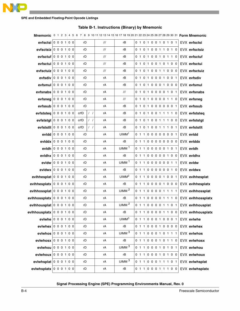
SPE and Embedded Floating-Point Opcode Listings
Signal Processing Engine (SPE) Programming Environments Manual, Rev. 0
B-4 Freescale Semiconductor
evfsctsi 0 0 0 1 0 0 rD /// rB 0 1 0 1 0 0 1 0 1 0 1 EVX evfsctsi
evfsctsiz 0 0 0 1 0 0 rD /// rB 0 1 0 1 0 0 1 1 0 1 0 EVX evfsctsiz
evfsctuf 0 0 0 1 0 0 rD /// rB 0 1 0 1 0 0 1 0 1 1 0 EVX evfsctuf
evfsctui 0 0 0 1 0 0 rD /// rB 0 1 0 1 0 0 1 0 1 0 0 EVX evfsctui
evfsctuiz 0 0 0 1 0 0 rD /// rB 0 1 0 1 0 0 1 1 0 0 0 EVX evfsctuiz
evfsdiv 0 0 0 1 0 0 rD rA rB 0 1 0 1 0 0 0 1 0 0 1 EVX evfsdiv
evfsmul 0 0 0 1 0 0 rD rA rB 0 1 0 1 0 0 0 1 0 0 0 EVX evfsmul
evfsnabs 0 0 0 1 0 0 rD rA /// 0 1 0 1 0 0 0 0 1 0 1 EVX evfsnabs
evfsneg 0 0 0 1 0 0 rD rA /// 0 1 0 1 0 0 0 0 1 1 0 EVX evfsneg
evfssub 0 0 0 1 0 0 rD rA rB 0 1 0 1 0 0 0 0 0 0 1 EVX evfssub
evfststeq 0 0 0 1 0 0 crfD / / rA rB 0 1 0 1 0 0 1 1 1 1 0 EVX evfststeq
evfststgt 0 0 0 1 0 0 crfD / / rA rB 0 1 0 1 0 0 1 1 1 0 0 EVX evfststgt
evfststlt 0 0 0 1 0 0 crfD / / rA rB 0 1 0 1 0 0 1 1 1 0 1 EVX evfststlt
evldd 0 0 0 1 0 0 rD rA UIMM1 0 1 1 0 0 0 0 0 0 0 1 EVX evldd
evlddx 0 0 0 1 0 0 rD rA rB 0 1 1 0 0 0 0 0 0 0 0 EVX evlddx
evldh 0 0 0 1 0 0 rD rA UIMM 1 0 1 1 0 0 0 0 0 1 0 1 EVX evldh
evldhx 0 0 0 1 0 0 rD rA rB 0 1 1 0 0 0 0 0 1 0 0 EVX evldhx
evldw 0 0 0 1 0 0 rD rA UIMM 1 0 1 1 0 0 0 0 0 0 1 1 EVX evldw
evldwx 0 0 0 1 0 0 rD rA rB 0 1 1 0 0 0 0 0 0 1 0 EVX evldwx
evlhhesplat 0 0 0 1 0 0 rD rA UIMM2 0 1 1 0 0 0 0 1 0 0 1 EVX evlhhesplat
evlhhesplatx 0 0 0 1 0 0 rD rA rB 0 1 1 0 0 0 0 1 0 0 0 EVX evlhhesplatx
evlhhossplat 0 0 0 1 0 0 rD rA UIMM 2 0 1 1 0 0 0 0 1 1 1 1 EVX evlhhossplat
evlhhossplatx 0 0 0 1 0 0 rD rA rB 0 1 1 0 0 0 0 1 1 1 0 EVX evlhhossplatx
evlhhousplat 0 0 0 1 0 0 rD rA UIMM 2 0 1 1 0 0 0 0 1 1 0 1 EVX evlhhousplat
evlhhousplatx 0 0 0 1 0 0 rD rA rB 0 1 1 0 0 0 0 1 1 0 0 EVX evlhhousplatx
evlwhe 0 0 0 1 0 0 rD rA UIMM3 0 1 1 0 0 0 1 0 0 0 1 EVX evlwhe
evlwhex 0 0 0 1 0 0 rD rA rB 0 1 1 0 0 0 1 0 0 0 0 EVX evlwhex
evlwhos 0 0 0 1 0 0 rD rA UIMM 3 0 1 1 0 0 0 1 0 1 1 1 EVX evlwhos
evlwhosx 0 0 0 1 0 0 rD rA rB 0 1 1 0 0 0 1 0 1 1 0 EVX evlwhosx
evlwhou 0 0 0 1 0 0 rD rA UIMM 3 0 1 1 0 0 0 1 0 1 0 1 EVX evlwhou
evlwhoux 0 0 0 1 0 0 rD rA rB 0 1 1 0 0 0 1 0 1 0 0 EVX evlwhoux
evlwhsplat 0 0 0 1 0 0 rD rA UIMM 3 0 1 1 0 0 0 1 1 1 0 1 EVX evlwhsplat
evlwhsplatx 0 0 0 1 0 0 rD rA rB 0 1 1 0 0 0 1 1 1 0 0 EVX evlwhsplatx
Table B-1. Instructions (Binary) by Mnemonic
Mnemonic 0 1 2 3 4 5 6 7 8 9 10 11 12 13 14 15 16 17 18 19 20 21 22 23 24 25 26 27 28 29 30 31 Form Mnemonic
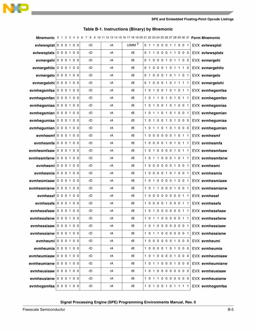
SPE and Embedded Floating-Point Opcode Listings
Signal Processing Engine (SPE) Programming Environments Manual, Rev. 0
Freescale Semiconductor B-5
evlwwsplat 0 0 0 1 0 0 rD rA UIMM 3 0 1 1 0 0 0 1 1 0 0 1 EVX evlwwsplat
evlwwsplatx 0 0 0 1 0 0 rD rA rB 0 1 1 0 0 0 1 1 0 0 0 EVX evlwwsplatx
evmergehi 0 0 0 1 0 0 rD rA rB 0 1 0 0 0 1 0 1 1 0 0 EVX evmergehi
evmergehilo 0 0 0 1 0 0 rD rA rB 0 1 0 0 0 1 0 1 1 1 0 EVX evmergehilo
evmergelo 0 0 0 1 0 0 rD rA rB 0 1 0 0 0 1 0 1 1 0 1 EVX evmergelo
evmergelohi 0 0 0 1 0 0 rD rA rB 0 1 0 0 0 1 0 1 1 1 1 EVX evmergelohi
evmhegsmfaa 0 0 0 1 0 0 rD rA rB 1 0 1 0 0 1 0 1 0 1 1 EVX evmhegsmfaa
evmhegsmfan 0 0 0 1 0 0 rD rA rB 1 0 1 1 0 1 0 1 0 1 1 EVX evmhegsmfan
evmhegsmiaa 0 0 0 1 0 0 rD rA rB 1 0 1 0 0 1 0 1 0 0 1 EVX evmhegsmiaa
evmhegsmian 0 0 0 1 0 0 rD rA rB 1 0 1 1 0 1 0 1 0 0 1 EVX evmhegsmian
evmhegumiaa 0 0 0 1 0 0 rD rA rB 1 0 1 0 0 1 0 1 0 0 0 EVX evmhegumiaa
evmhegumian 0 0 0 1 0 0 rD rA rB 1 0 1 1 0 1 0 1 0 0 0 EVX evmhegumian
evmhesmf 0 0 0 1 0 0 rD rA rB 1 0 0 0 0 0 0 1 0 1 1 EVX evmhesmf
evmhesmfa 0 0 0 1 0 0 rD rA rB 1 0 0 0 0 1 0 1 0 1 1 EVX evmhesmfa
evmhesmfaaw 0 0 0 1 0 0 rD rA rB 1 0 1 0 0 0 0 1 0 1 1 EVX evmhesmfaaw
evmhesmfanw 0 0 0 1 0 0 rD rA rB 1 0 1 1 0 0 0 1 0 1 1 EVX evmhesmfanw
evmhesmi 0 0 0 1 0 0 rD rA rB 1 0 0 0 0 0 0 1 0 0 1 EVX evmhesmi
evmhesmia 0 0 0 1 0 0 rD rA rB 1 0 0 0 0 1 0 1 0 0 1 EVX evmhesmia
evmhesmiaaw 0 0 0 1 0 0 rD rA rB 1 0 1 0 0 0 0 1 0 0 1 EVX evmhesmiaaw
evmhesmianw 0 0 0 1 0 0 rD rA rB 1 0 1 1 0 0 0 1 0 0 1 EVX evmhesmianw
evmhessf 0 0 0 1 0 0 rD rA rB 1 0 0 0 0 0 0 0 0 1 1 EVX evmhessf
evmhessfa 0 0 0 1 0 0 rD rA rB 1 0 0 0 0 1 0 0 0 1 1 EVX evmhessfa
evmhessfaaw 0 0 0 1 0 0 rD rA rB 1 0 1 0 0 0 0 0 0 1 1 EVX evmhessfaaw
evmhessfanw 0 0 0 1 0 0 rD rA rB 1 0 1 1 0 0 0 0 0 1 1 EVX evmhessfanw
evmhessiaaw 0 0 0 1 0 0 rD rA rB 1 0 1 0 0 0 0 0 0 0 1 EVX evmhessiaaw
evmhessianw 0 0 0 1 0 0 rD rA rB 1 0 1 1 0 0 0 0 0 0 1 EVX evmhessianw
evmheumi 0 0 0 1 0 0 rD rA rB 1 0 0 0 0 0 0 1 0 0 0 EVX evmheumi
evmheumia 0 0 0 1 0 0 rD rA rB 1 0 0 0 0 1 0 1 0 0 0 EVX evmheumia
evmheumiaaw 0 0 0 1 0 0 rD rA rB 1 0 1 0 0 0 0 1 0 0 0 EVX evmheumiaaw
evmheumianw 0 0 0 1 0 0 rD rA rB 1 0 1 1 0 0 0 1 0 0 0 EVX evmheumianw
evmheusiaaw 0 0 0 1 0 0 rD rA rB 1 0 1 0 0 0 0 0 0 0 0 EVX evmheusiaaw
evmheusianw 0 0 0 1 0 0 rD rA rB 1 0 1 1 0 0 0 0 0 0 0 EVX evmheusianw
evmhogsmfaa 0 0 0 1 0 0 rD rA rB 1 0 1 0 0 1 0 1 1 1 1 EVX evmhogsmfaa
Table B-1. Instructions (Binary) by Mnemonic
Mnemonic 0 1 2 3 4 5 6 7 8 9 10 11 12 13 14 15 16 17 18 19 20 21 22 23 24 25 26 27 28 29 30 31 Form Mnemonic
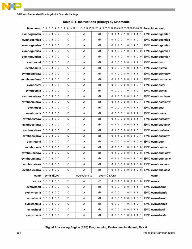
SPE and Embedded Floating-Point Opcode Listings
Signal Processing Engine (SPE) Programming Environments Manual, Rev. 0
B-6 Freescale Semiconductor
evmhogsmfan 0 0 0 1 0 0 rD rA rB 1 0 1 1 0 1 0 1 1 1 1 EVX evmhogsmfan
evmhogsmiaa 0 0 0 1 0 0 rD rA rB 1 0 1 0 0 1 0 1 1 0 1 EVX evmhogsmiaa
evmhogsmian 0 0 0 1 0 0 rD rA rB 1 0 1 1 0 1 0 1 1 0 1 EVX evmhogsmian
evmhogumiaa 0 0 0 1 0 0 rD rA rB 1 0 1 0 0 1 0 1 1 0 0 EVX evmhogumiaa
evmhogumian 0 0 0 1 0 0 rD rA rB 1 0 1 1 0 1 0 1 1 0 0 EVX evmhogumian
evmhosmf 0 0 0 1 0 0 rD rA rB 1 0 0 0 0 0 0 1 1 1 1 EVX evmhosmf
evmhosmfa 0 0 0 1 0 0 rD rA rB 1 0 0 0 0 1 0 1 1 1 1 EVX evmhosmfa
evmhosmfaaw 0 0 0 1 0 0 rD rA rB 1 0 1 0 0 0 0 1 1 1 1 EVX evmhosmfaaw
evmhosmfanw 0 0 0 1 0 0 rD rA rB 1 0 1 1 0 0 0 1 1 1 1 EVX evmhosmfanw
evmhosmi 0 0 0 1 0 0 rD rA rB 1 0 0 0 0 0 0 1 1 0 1 EVX evmhosmi
evmhosmia 0 0 0 1 0 0 rD rA rB 1 0 0 0 0 1 0 1 1 0 1 EVX evmhosmia
evmhosmiaaw 0 0 0 1 0 0 rD rA rB 1 0 1 0 0 0 0 1 1 0 1 EVX evmhosmiaaw
evmhosmianw 0 0 0 1 0 0 rD rA rB 1 0 1 1 0 0 0 1 1 0 1 EVX evmhosmianw
evmhossf 0 0 0 1 0 0 rD rA rB 1 0 0 0 0 0 0 0 1 1 1 EVX evmhossf
evmhossfa 0 0 0 1 0 0 rD rA rB 1 0 0 0 0 1 0 0 1 1 1 EVX evmhossfa
evmhossfaaw 0 0 0 1 0 0 rD rA rB 1 0 1 0 0 0 0 0 1 1 1 EVX evmhossfaaw
evmhossfanw 0 0 0 1 0 0 rD rA rB 1 0 1 1 0 0 0 0 1 1 1 EVX evmhossfanw
evmhossiaaw 0 0 0 1 0 0 rD rA rB 1 0 1 0 0 0 0 0 1 0 1 EVX evmhossiaaw
evmhossianw 0 0 0 1 0 0 rD rA rB 1 0 1 1 0 0 0 0 1 0 1 EVX evmhossianw
evmhoumi 0 0 0 1 0 0 rD rA rB 1 0 0 0 0 0 0 1 1 0 0 EVX evmhoumi
evmhoumia 0 0 0 1 0 0 rD rA rB 1 0 0 0 0 1 0 1 1 0 0 EVX evmhoumia
evmhoumiaaw 0 0 0 1 0 0 rD rA rB 1 0 1 0 0 0 0 1 1 0 0 EVX evmhoumiaaw
evmhoumianw 0 0 0 1 0 0 rD rA rB 1 0 1 1 0 0 0 1 1 0 0 EVX evmhoumianw
evmhousiaaw 0 0 0 1 0 0 rD rA rB 1 0 1 0 0 0 0 0 1 0 0 EVX evmhousiaaw
evmhousianw 0 0 0 1 0 0 rD rA rB 1 0 1 1 0 0 0 0 1 0 0 EVX evmhousianw
evmr evmr rD,rA equivalent to evor rD,rA,rA evmr
evmra 0 0 0 1 0 0 rD rA /// 1 0 0 1 1 0 0 0 1 0 0 EVX evmra
evmwhsmf 0 0 0 1 0 0 rD rA rB 1 0 0 0 1 0 0 1 1 1 1 EVX evmwhsmf
evmwhsmfa 0 0 0 1 0 0 rD rA rB 1 0 0 0 1 1 0 1 1 1 1 EVX evmwhsmfa
evmwhsmi 0 0 0 1 0 0 rD rA rB 1 0 0 0 1 0 0 1 1 0 1 EVX evmwhsmi
evmwhsmia 0 0 0 1 0 0 rD rA rB 1 0 0 0 1 1 0 1 1 0 1 EVX evmwhsmia
evmwhssf 0 0 0 1 0 0 rD rA rB 1 0 0 0 1 0 0 0 1 1 1 EVX evmwhssf
evmwhssfa 0 0 0 1 0 0 rD rA rB 1 0 0 0 1 1 0 0 1 1 1 EVX evmwhssfa
Table B-1. Instructions (Binary) by Mnemonic
Mnemonic 0 1 2 3 4 5 6 7 8 9 10 11 12 13 14 15 16 17 18 19 20 21 22 23 24 25 26 27 28 29 30 31 Form Mnemonic
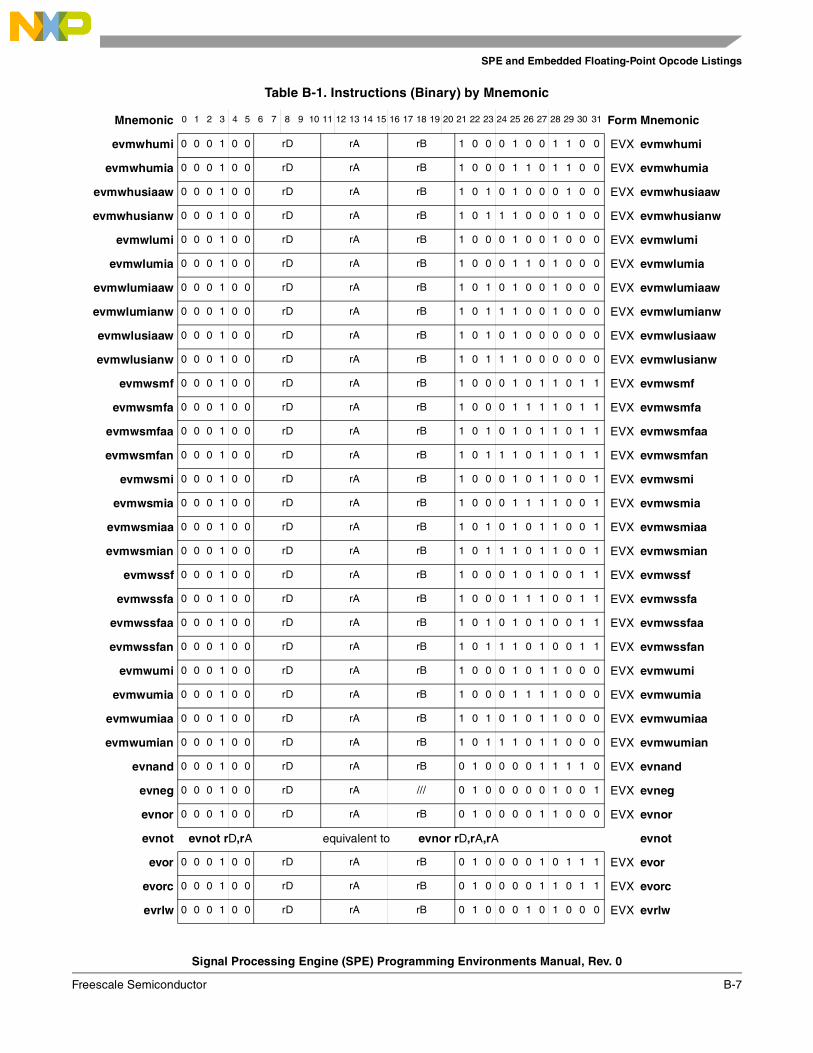
SPE and Embedded Floating-Point Opcode Listings
Signal Processing Engine (SPE) Programming Environments Manual, Rev. 0
Freescale Semiconductor B-7
evmwhumi 0 0 0 1 0 0 rD rA rB 1 0 0 0 1 0 0 1 1 0 0 EVX evmwhumi
evmwhumia 0 0 0 1 0 0 rD rA rB 1 0 0 0 1 1 0 1 1 0 0 EVX evmwhumia
evmwhusiaaw 0 0 0 1 0 0 rD rA rB 1 0 1 0 1 0 0 0 1 0 0 EVX evmwhusiaaw
evmwhusianw 0 0 0 1 0 0 rD rA rB 1 0 1 1 1 0 0 0 1 0 0 EVX evmwhusianw
evmwlumi 0 0 0 1 0 0 rD rA rB 1 0 0 0 1 0 0 1 0 0 0 EVX evmwlumi
evmwlumia 0 0 0 1 0 0 rD rA rB 1 0 0 0 1 1 0 1 0 0 0 EVX evmwlumia
evmwlumiaaw 0 0 0 1 0 0 rD rA rB 1 0 1 0 1 0 0 1 0 0 0 EVX evmwlumiaaw
evmwlumianw 0 0 0 1 0 0 rD rA rB 1 0 1 1 1 0 0 1 0 0 0 EVX evmwlumianw
evmwlusiaaw 0 0 0 1 0 0 rD rA rB 1 0 1 0 1 0 0 0 0 0 0 EVX evmwlusiaaw
evmwlusianw 0 0 0 1 0 0 rD rA rB 1 0 1 1 1 0 0 0 0 0 0 EVX evmwlusianw
evmwsmf 0 0 0 1 0 0 rD rA rB 1 0 0 0 1 0 1 1 0 1 1 EVX evmwsmf
evmwsmfa 0 0 0 1 0 0 rD rA rB 1 0 0 0 1 1 1 1 0 1 1 EVX evmwsmfa
evmwsmfaa 0 0 0 1 0 0 rD rA rB 1 0 1 0 1 0 1 1 0 1 1 EVX evmwsmfaa
evmwsmfan 0 0 0 1 0 0 rD rA rB 1 0 1 1 1 0 1 1 0 1 1 EVX evmwsmfan
evmwsmi 0 0 0 1 0 0 rD rA rB 1 0 0 0 1 0 1 1 0 0 1 EVX evmwsmi
evmwsmia 0 0 0 1 0 0 rD rA rB 1 0 0 0 1 1 1 1 0 0 1 EVX evmwsmia
evmwsmiaa 0 0 0 1 0 0 rD rA rB 1 0 1 0 1 0 1 1 0 0 1 EVX evmwsmiaa
evmwsmian 0 0 0 1 0 0 rD rA rB 1 0 1 1 1 0 1 1 0 0 1 EVX evmwsmian
evmwssf 0 0 0 1 0 0 rD rA rB 1 0 0 0 1 0 1 0 0 1 1 EVX evmwssf
evmwssfa 0 0 0 1 0 0 rD rA rB 1 0 0 0 1 1 1 0 0 1 1 EVX evmwssfa
evmwssfaa 0 0 0 1 0 0 rD rA rB 1 0 1 0 1 0 1 0 0 1 1 EVX evmwssfaa
evmwssfan 0 0 0 1 0 0 rD rA rB 1 0 1 1 1 0 1 0 0 1 1 EVX evmwssfan
evmwumi 0 0 0 1 0 0 rD rA rB 1 0 0 0 1 0 1 1 0 0 0 EVX evmwumi
evmwumia 0 0 0 1 0 0 rD rA rB 1 0 0 0 1 1 1 1 0 0 0 EVX evmwumia
evmwumiaa 0 0 0 1 0 0 rD rA rB 1 0 1 0 1 0 1 1 0 0 0 EVX evmwumiaa
evmwumian 0 0 0 1 0 0 rD rA rB 1 0 1 1 1 0 1 1 0 0 0 EVX evmwumian
evnand 0 0 0 1 0 0 rD rA rB 0 1 0 0 0 0 1 1 1 1 0 EVX evnand
evneg 0 0 0 1 0 0 rD rA /// 0 1 0 0 0 0 0 1 0 0 1 EVX evneg
evnor 0 0 0 1 0 0 rD rA rB 0 1 0 0 0 0 1 1 0 0 0 EVX evnor
evnot evnot rD,rA equivalent to evnor rD,rA,rA evnot
evor 0 0 0 1 0 0 rD rA rB 0 1 0 0 0 0 1 0 1 1 1 EVX evor
evorc 0 0 0 1 0 0 rD rA rB 0 1 0 0 0 0 1 1 0 1 1 EVX evorc
evrlw 0 0 0 1 0 0 rD rA rB 0 1 0 0 0 1 0 1 0 0 0 EVX evrlw
Table B-1. Instructions (Binary) by Mnemonic
Mnemonic 0 1 2 3 4 5 6 7 8 9 10 11 12 13 14 15 16 17 18 19 20 21 22 23 24 25 26 27 28 29 30 31 Form Mnemonic
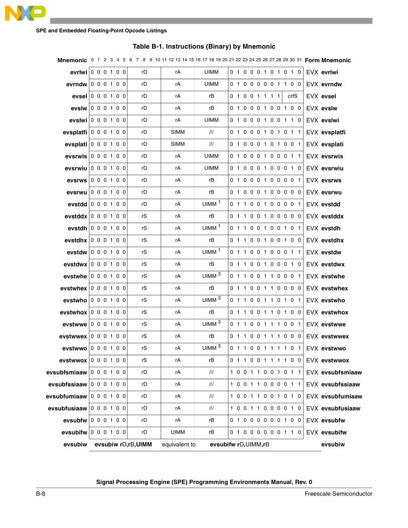
SPE and Embedded Floating-Point Opcode Listings
Signal Processing Engine (SPE) Programming Environments Manual, Rev. 0
B-8 Freescale Semiconductor
evrlwi 0 0 0 1 0 0 rD rA UIMM 0 1 0 0 0 1 0 1 0 1 0 EVX evrlwi
evrndw 0 0 0 1 0 0 rD rA UIMM 0 1 0 0 0 0 0 1 1 0 0 EVX evrndw
evsel 0 0 0 1 0 0 rD rA rB 0 1 0 0 1 1 1 1 crfS EVX evsel
evslw 0 0 0 1 0 0 rD rA rB 0 1 0 0 0 1 0 0 1 0 0 EVX evslw
evslwi 0 0 0 1 0 0 rD rA UIMM 0 1 0 0 0 1 0 0 1 1 0 EVX evslwi
evsplatfi 0 0 0 1 0 0 rD SIMM /// 0 1 0 0 0 1 0 1 0 1 1 EVX evsplatfi
evsplati 0 0 0 1 0 0 rD SIMM /// 0 1 0 0 0 1 0 1 0 0 1 EVX evsplati
evsrwis 0 0 0 1 0 0 rD rA UIMM 0 1 0 0 0 1 0 0 0 1 1 EVX evsrwis
evsrwiu 0 0 0 1 0 0 rD rA UIMM 0 1 0 0 0 1 0 0 0 1 0 EVX evsrwiu
evsrws 0 0 0 1 0 0 rD rA rB 0 1 0 0 0 1 0 0 0 0 1 EVX evsrws
evsrwu 0 0 0 1 0 0 rD rA rB 0 1 0 0 0 1 0 0 0 0 0 EVX evsrwu
evstdd 0 0 0 1 0 0 rD rA UIMM 1 0 1 1 0 0 1 0 0 0 0 1 EVX evstdd
evstddx 0 0 0 1 0 0 rS rA rB 0 1 1 0 0 1 0 0 0 0 0 EVX evstddx
evstdh 0 0 0 1 0 0 rS rA UIMM 1 0 1 1 0 0 1 0 0 1 0 1 EVX evstdh
evstdhx 0 0 0 1 0 0 rS rA rB 0 1 1 0 0 1 0 0 1 0 0 EVX evstdhx
evstdw 0 0 0 1 0 0 rS rA UIMM 1 0 1 1 0 0 1 0 0 0 1 1 EVX evstdw
evstdwx 0 0 0 1 0 0 rS rA rB 0 1 1 0 0 1 0 0 0 1 0 EVX evstdwx
evstwhe 0 0 0 1 0 0 rS rA UIMM 3 0 1 1 0 0 1 1 0 0 0 1 EVX evstwhe
evstwhex 0 0 0 1 0 0 rS rA rB 0 1 1 0 0 1 1 0 0 0 0 EVX evstwhex
evstwho 0 0 0 1 0 0 rS rA UIMM 3 0 1 1 0 0 1 1 0 1 0 1 EVX evstwho
evstwhox 0 0 0 1 0 0 rS rA rB 0 1 1 0 0 1 1 0 1 0 0 EVX evstwhox
evstwwe 0 0 0 1 0 0 rS rA UIMM 3 0 1 1 0 0 1 1 1 0 0 1 EVX evstwwe
evstwwex 0 0 0 1 0 0 rS rA rB 0 1 1 0 0 1 1 1 0 0 0 EVX evstwwex
evstwwo 0 0 0 1 0 0 rS rA UIMM 3 0 1 1 0 0 1 1 1 1 0 1 EVX evstwwo
evstwwox 0 0 0 1 0 0 rS rA rB 0 1 1 0 0 1 1 1 1 0 0 EVX evstwwox
evsubfsmiaaw 0 0 0 1 0 0 rD rA /// 1 0 0 1 1 0 0 1 0 1 1 EVX evsubfsmiaaw
evsubfssiaaw 0 0 0 1 0 0 rD rA /// 1 0 0 1 1 0 0 0 0 1 1 EVX evsubfssiaaw
evsubfumiaaw 0 0 0 1 0 0 rD rA /// 1 0 0 1 1 0 0 1 0 1 0 EVX evsubfumiaaw
evsubfusiaaw 0 0 0 1 0 0 rD rA /// 1 0 0 1 1 0 0 0 0 1 0 EVX evsubfusiaaw
evsubfw 0 0 0 1 0 0 rD rA rB 0 1 0 0 0 0 0 0 1 0 0 EVX evsubfw
evsubifw 0 0 0 1 0 0 rD UIMM rB 0 1 0 0 0 0 0 0 1 1 0 EVX evsubifw
evsubiw evsubiw rD,rB,UIMM equivalent to evsubifw rD,UIMM,rB evsubiw
Table B-1. Instructions (Binary) by Mnemonic
Mnemonic 0 1 2 3 4 5 6 7 8 9 10 11 12 13 14 15 16 17 18 19 20 21 22 23 24 25 26 27 28 29 30 31 Form Mnemonic
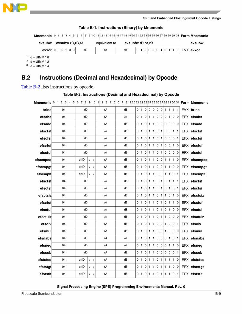
SPE and Embedded Floating-Point Opcode Listings
Signal Processing Engine (SPE) Programming Environments Manual, Rev. 0
Freescale Semiconductor B-9
B.2 Instructions (Decimal and Hexadecimal) by OpcodeTable B-2 lists instructions by opcode.
evsubw evsubw rD,rB,rA equivalent to evsubfw rD,rA,rB evsubw
evxor 0 0 0 1 0 0 rD rA rB 0 1 0 0 0 0 1 0 1 1 0 EVX evxor
1 d = UIMM * 82 d = UIMM * 23 d = UIMM * 4
Table B-2. Instructions (Decimal and Hexadecimal) by Opcode
Mnemonic 0 1 2 3 4 5 6 7 8 9 10 11 12 13 14 15 16 17 18 19 20 21 22 23 24 25 26 27 28 29 30 31 Form Mnemonic
brinc 04 rD rA rB 0 1 0 0 0 0 0 1 1 1 1 EVX brinc
efsabs 04 rD rA /// 0 1 0 1 1 0 0 0 1 0 0 EFX efsabs
efsadd 04 rD rA rB 0 1 0 1 1 0 0 0 0 0 0 EFX efsadd
efscfsf 04 rD /// rB 0 1 0 1 1 0 1 0 0 1 1 EFX efscfsf
efscfsi 04 rD /// rB 0 1 0 1 1 0 1 0 0 0 1 EFX efscfsi
efscfuf 04 rD /// rB 0 1 0 1 1 0 1 0 0 1 0 EFX efscfuf
efscfui 04 rD /// rB 0 1 0 1 1 0 1 0 0 0 0 EFX efscfui
efscmpeq 04 crfD / / rA rB 0 1 0 1 1 0 0 1 1 1 0 EFX efscmpeq
efscmpgt 04 crfD / / rA rB 0 1 0 1 1 0 0 1 1 0 0 EFX efscmpgt
efscmplt 04 crfD / / rA rB 0 1 0 1 1 0 0 1 1 0 1 EFX efscmplt
efsctsf 04 rD /// rB 0 1 0 1 1 0 1 0 1 1 1 EFX efsctsf
efsctsi 04 rD /// rB 0 1 0 1 1 0 1 0 1 0 1 EFX efsctsi
efsctsiz 04 rD /// rB 0 1 0 1 1 0 1 1 0 1 0 EFX efsctsiz
efsctuf 04 rD /// rB 0 1 0 1 1 0 1 0 1 1 0 EFX efsctuf
efsctui 04 rD /// rB 0 1 0 1 1 0 1 0 1 0 0 EFX efsctui
efsctuiz 04 rD /// rB 0 1 0 1 1 0 1 1 0 0 0 EFX efsctuiz
efsdiv 04 rD rA rB 0 1 0 1 1 0 0 1 0 0 1 EFX efsdiv
efsmul 04 rD rA rB 0 1 0 1 1 0 0 1 0 0 0 EFX efsmul
efsnabs 04 rD rA /// 0 1 0 1 1 0 0 0 1 0 1 EFX efsnabs
efsneg 04 rD rA /// 0 1 0 1 1 0 0 0 1 1 0 EFX efsneg
efssub 04 rD rA rB 0 1 0 1 1 0 0 0 0 0 1 EFX efssub
efststeq 04 crfD / / rA rB 0 1 0 1 1 0 1 1 1 1 0 EFX efststeq
efststgt 04 crfD / / rA rB 0 1 0 1 1 0 1 1 1 0 0 EFX efststgt
efststlt 04 crfD / / rA rB 0 1 0 1 1 0 1 1 1 0 1 EFX efststlt
Table B-1. Instructions (Binary) by Mnemonic
Mnemonic 0 1 2 3 4 5 6 7 8 9 10 11 12 13 14 15 16 17 18 19 20 21 22 23 24 25 26 27 28 29 30 31 Form Mnemonic
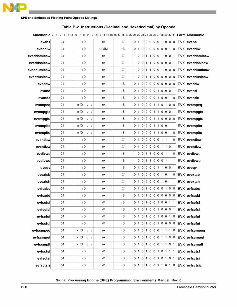
SPE and Embedded Floating-Point Opcode Listings
Signal Processing Engine (SPE) Programming Environments Manual, Rev. 0
B-10 Freescale Semiconductor
evabs 04 rD rA /// 0 1 0 0 0 0 0 1 0 0 0 EVX evabs
evaddiw 04 rD UIMM rB 0 1 0 0 0 0 0 0 0 1 0 EVX evaddiw
evaddsmiaaw 04 rD rA /// 1 0 0 1 1 0 0 1 0 0 1 EVX evaddsmiaaw
evaddssiaaw 04 rD rA /// 1 0 0 1 1 0 0 0 0 0 1 EVX evaddssiaaw
evaddumiaaw 04 rD rA /// 1 0 0 1 1 0 0 1 0 0 0 EVX evaddumiaaw
evaddusiaaw 04 rD rA /// 1 0 0 1 1 0 0 0 0 0 0 EVX evaddusiaaw
evaddw 04 rD rA rB 0 1 0 0 0 0 0 0 0 0 0 EVX evaddw
evand 04 rD rA rB 0 1 0 0 0 0 1 0 0 0 1 EVX evand
evandc 04 rD rA rB 0 1 0 0 0 0 1 0 0 1 0 EVX evandc
evcmpeq 04 crfD / / rA rB 0 1 0 0 0 1 1 0 1 0 0 EVX evcmpeq
evcmpgts 04 crfD / / rA rB 0 1 0 0 0 1 1 0 0 0 1 EVX evcmpgts
evcmpgtu 04 crfD / / rA rB 0 1 0 0 0 1 1 0 0 0 0 EVX evcmpgtu
evcmplts 04 crfD / / rA rB 0 1 0 0 0 1 1 0 0 1 1 EVX evcmplts
evcmpltu 04 crfD / / rA rB 0 1 0 0 0 1 1 0 0 1 0 EVX evcmpltu
evcntlsw 04 rD rA /// 0 1 0 0 0 0 0 1 1 1 0 EVX evcntlsw
evcntlzw 04 rD rA /// 0 1 0 0 0 0 0 1 1 0 1 EVX evcntlzw
evdivws 04 rD rA rB 1 0 0 1 1 0 0 0 1 1 0 EVX evdivws
evdivwu 04 rD rA rB 1 0 0 1 1 0 0 0 1 1 1 EVX evdivwu
eveqv 04 rD rA rB 0 1 0 0 0 0 1 1 0 0 1 EVX eveqv
evextsb 04 rD rA /// 0 1 0 0 0 0 0 1 0 1 0 EVX evextsb
evextsh 04 rD rA /// 0 1 0 0 0 0 0 1 0 1 1 EVX evextsh
evfsabs 04 rD rA /// 0 1 0 1 0 0 0 0 1 0 0 EVX evfsabs
evfsadd 04 rD rA rB 0 1 0 1 0 0 0 0 0 0 0 EVX evfsadd
evfscfsf 04 rD /// rB 0 1 0 1 0 0 1 0 0 1 1 EVX evfscfsf
evfscfsi 04 rD /// rB 0 1 0 1 0 0 1 0 0 0 1 EVX evfscfsi
evfscfuf 04 rD /// rB 0 1 0 1 0 0 1 0 0 1 0 EVX evfscfuf
evfscfui 04 rD /// rB 0 1 0 1 0 0 1 0 0 0 0 EVX evfscfui
evfscmpeq 04 crfD / / rA rB 0 1 0 1 0 0 0 1 1 1 0 EVX evfscmpeq
evfscmpgt 04 crfD / / rA rB 0 1 0 1 0 0 0 1 1 0 0 EVX evfscmpgt
evfscmplt 04 crfD / / rA rB 0 1 0 1 0 0 0 1 1 0 1 EVX evfscmplt
evfsctsf 04 rD /// rB 0 1 0 1 0 0 1 0 1 1 1 EVX evfsctsf
evfsctsi 04 rD /// rB 0 1 0 1 0 0 1 0 1 0 1 EVX evfsctsi
evfsctsiz 04 rD /// rB 0 1 0 1 0 0 1 1 0 1 0 EVX evfsctsiz
Table B-2. Instructions (Decimal and Hexadecimal) by Opcode
Mnemonic 0 1 2 3 4 5 6 7 8 9 10 11 12 13 14 15 16 17 18 19 20 21 22 23 24 25 26 27 28 29 30 31 Form Mnemonic
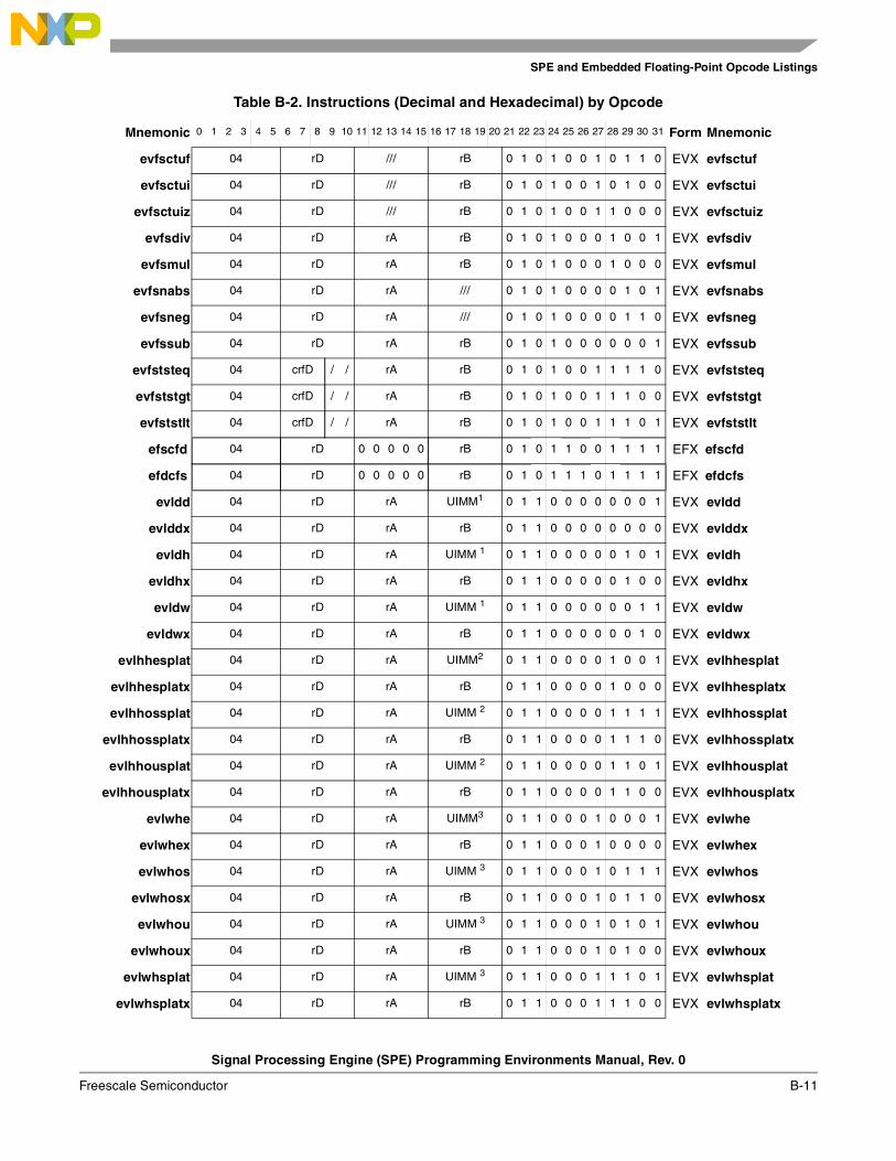
SPE and Embedded Floating-Point Opcode Listings
Signal Processing Engine (SPE) Programming Environments Manual, Rev. 0
Freescale Semiconductor B-11
evfsctuf 04 rD /// rB 0 1 0 1 0 0 1 0 1 1 0 EVX evfsctuf
evfsctui 04 rD /// rB 0 1 0 1 0 0 1 0 1 0 0 EVX evfsctui
evfsctuiz 04 rD /// rB 0 1 0 1 0 0 1 1 0 0 0 EVX evfsctuiz
evfsdiv 04 rD rA rB 0 1 0 1 0 0 0 1 0 0 1 EVX evfsdiv
evfsmul 04 rD rA rB 0 1 0 1 0 0 0 1 0 0 0 EVX evfsmul
evfsnabs 04 rD rA /// 0 1 0 1 0 0 0 0 1 0 1 EVX evfsnabs
evfsneg 04 rD rA /// 0 1 0 1 0 0 0 0 1 1 0 EVX evfsneg
evfssub 04 rD rA rB 0 1 0 1 0 0 0 0 0 0 1 EVX evfssub
evfststeq 04 crfD / / rA rB 0 1 0 1 0 0 1 1 1 1 0 EVX evfststeq
evfststgt 04 crfD / / rA rB 0 1 0 1 0 0 1 1 1 0 0 EVX evfststgt
evfststlt 04 crfD / / rA rB 0 1 0 1 0 0 1 1 1 0 1 EVX evfststlt
efscfd 04 rD 0 0 0 0 0 rB 0 1 0 1 1 0 0 1 1 1 1 EFX efscfd
efdcfs 04 rD 0 0 0 0 0 rB 0 1 0 1 1 1 0 1 1 1 1 EFX efdcfs
evldd 04 rD rA UIMM1 0 1 1 0 0 0 0 0 0 0 1 EVX evldd
evlddx 04 rD rA rB 0 1 1 0 0 0 0 0 0 0 0 EVX evlddx
evldh 04 rD rA UIMM 1 0 1 1 0 0 0 0 0 1 0 1 EVX evldh
evldhx 04 rD rA rB 0 1 1 0 0 0 0 0 1 0 0 EVX evldhx
evldw 04 rD rA UIMM 1 0 1 1 0 0 0 0 0 0 1 1 EVX evldw
evldwx 04 rD rA rB 0 1 1 0 0 0 0 0 0 1 0 EVX evldwx
evlhhesplat 04 rD rA UIMM2 0 1 1 0 0 0 0 1 0 0 1 EVX evlhhesplat
evlhhesplatx 04 rD rA rB 0 1 1 0 0 0 0 1 0 0 0 EVX evlhhesplatx
evlhhossplat 04 rD rA UIMM 2 0 1 1 0 0 0 0 1 1 1 1 EVX evlhhossplat
evlhhossplatx 04 rD rA rB 0 1 1 0 0 0 0 1 1 1 0 EVX evlhhossplatx
evlhhousplat 04 rD rA UIMM 2 0 1 1 0 0 0 0 1 1 0 1 EVX evlhhousplat
evlhhousplatx 04 rD rA rB 0 1 1 0 0 0 0 1 1 0 0 EVX evlhhousplatx
evlwhe 04 rD rA UIMM3 0 1 1 0 0 0 1 0 0 0 1 EVX evlwhe
evlwhex 04 rD rA rB 0 1 1 0 0 0 1 0 0 0 0 EVX evlwhex
evlwhos 04 rD rA UIMM 3 0 1 1 0 0 0 1 0 1 1 1 EVX evlwhos
evlwhosx 04 rD rA rB 0 1 1 0 0 0 1 0 1 1 0 EVX evlwhosx
evlwhou 04 rD rA UIMM 3 0 1 1 0 0 0 1 0 1 0 1 EVX evlwhou
evlwhoux 04 rD rA rB 0 1 1 0 0 0 1 0 1 0 0 EVX evlwhoux
evlwhsplat 04 rD rA UIMM 3 0 1 1 0 0 0 1 1 1 0 1 EVX evlwhsplat
evlwhsplatx 04 rD rA rB 0 1 1 0 0 0 1 1 1 0 0 EVX evlwhsplatx
Table B-2. Instructions (Decimal and Hexadecimal) by Opcode
Mnemonic 0 1 2 3 4 5 6 7 8 9 10 11 12 13 14 15 16 17 18 19 20 21 22 23 24 25 26 27 28 29 30 31 Form Mnemonic
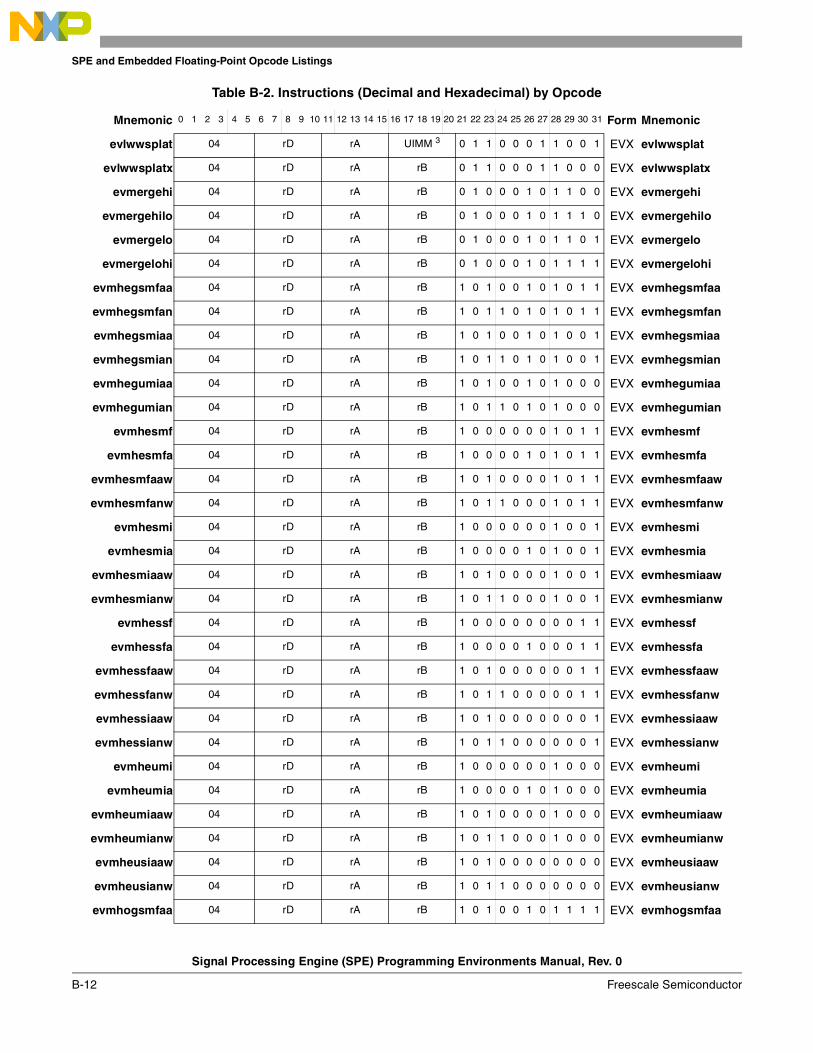
SPE and Embedded Floating-Point Opcode Listings
Signal Processing Engine (SPE) Programming Environments Manual, Rev. 0
B-12 Freescale Semiconductor
evlwwsplat 04 rD rA UIMM 3 0 1 1 0 0 0 1 1 0 0 1 EVX evlwwsplat
evlwwsplatx 04 rD rA rB 0 1 1 0 0 0 1 1 0 0 0 EVX evlwwsplatx
evmergehi 04 rD rA rB 0 1 0 0 0 1 0 1 1 0 0 EVX evmergehi
evmergehilo 04 rD rA rB 0 1 0 0 0 1 0 1 1 1 0 EVX evmergehilo
evmergelo 04 rD rA rB 0 1 0 0 0 1 0 1 1 0 1 EVX evmergelo
evmergelohi 04 rD rA rB 0 1 0 0 0 1 0 1 1 1 1 EVX evmergelohi
evmhegsmfaa 04 rD rA rB 1 0 1 0 0 1 0 1 0 1 1 EVX evmhegsmfaa
evmhegsmfan 04 rD rA rB 1 0 1 1 0 1 0 1 0 1 1 EVX evmhegsmfan
evmhegsmiaa 04 rD rA rB 1 0 1 0 0 1 0 1 0 0 1 EVX evmhegsmiaa
evmhegsmian 04 rD rA rB 1 0 1 1 0 1 0 1 0 0 1 EVX evmhegsmian
evmhegumiaa 04 rD rA rB 1 0 1 0 0 1 0 1 0 0 0 EVX evmhegumiaa
evmhegumian 04 rD rA rB 1 0 1 1 0 1 0 1 0 0 0 EVX evmhegumian
evmhesmf 04 rD rA rB 1 0 0 0 0 0 0 1 0 1 1 EVX evmhesmf
evmhesmfa 04 rD rA rB 1 0 0 0 0 1 0 1 0 1 1 EVX evmhesmfa
evmhesmfaaw 04 rD rA rB 1 0 1 0 0 0 0 1 0 1 1 EVX evmhesmfaaw
evmhesmfanw 04 rD rA rB 1 0 1 1 0 0 0 1 0 1 1 EVX evmhesmfanw
evmhesmi 04 rD rA rB 1 0 0 0 0 0 0 1 0 0 1 EVX evmhesmi
evmhesmia 04 rD rA rB 1 0 0 0 0 1 0 1 0 0 1 EVX evmhesmia
evmhesmiaaw 04 rD rA rB 1 0 1 0 0 0 0 1 0 0 1 EVX evmhesmiaaw
evmhesmianw 04 rD rA rB 1 0 1 1 0 0 0 1 0 0 1 EVX evmhesmianw
evmhessf 04 rD rA rB 1 0 0 0 0 0 0 0 0 1 1 EVX evmhessf
evmhessfa 04 rD rA rB 1 0 0 0 0 1 0 0 0 1 1 EVX evmhessfa
evmhessfaaw 04 rD rA rB 1 0 1 0 0 0 0 0 0 1 1 EVX evmhessfaaw
evmhessfanw 04 rD rA rB 1 0 1 1 0 0 0 0 0 1 1 EVX evmhessfanw
evmhessiaaw 04 rD rA rB 1 0 1 0 0 0 0 0 0 0 1 EVX evmhessiaaw
evmhessianw 04 rD rA rB 1 0 1 1 0 0 0 0 0 0 1 EVX evmhessianw
evmheumi 04 rD rA rB 1 0 0 0 0 0 0 1 0 0 0 EVX evmheumi
evmheumia 04 rD rA rB 1 0 0 0 0 1 0 1 0 0 0 EVX evmheumia
evmheumiaaw 04 rD rA rB 1 0 1 0 0 0 0 1 0 0 0 EVX evmheumiaaw
evmheumianw 04 rD rA rB 1 0 1 1 0 0 0 1 0 0 0 EVX evmheumianw
evmheusiaaw 04 rD rA rB 1 0 1 0 0 0 0 0 0 0 0 EVX evmheusiaaw
evmheusianw 04 rD rA rB 1 0 1 1 0 0 0 0 0 0 0 EVX evmheusianw
evmhogsmfaa 04 rD rA rB 1 0 1 0 0 1 0 1 1 1 1 EVX evmhogsmfaa
Table B-2. Instructions (Decimal and Hexadecimal) by Opcode
Mnemonic 0 1 2 3 4 5 6 7 8 9 10 11 12 13 14 15 16 17 18 19 20 21 22 23 24 25 26 27 28 29 30 31 Form Mnemonic
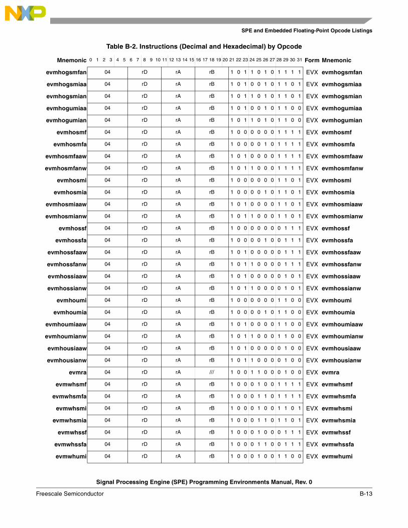
SPE and Embedded Floating-Point Opcode Listings
Signal Processing Engine (SPE) Programming Environments Manual, Rev. 0
Freescale Semiconductor B-13
evmhogsmfan 04 rD rA rB 1 0 1 1 0 1 0 1 1 1 1 EVX evmhogsmfan
evmhogsmiaa 04 rD rA rB 1 0 1 0 0 1 0 1 1 0 1 EVX evmhogsmiaa
evmhogsmian 04 rD rA rB 1 0 1 1 0 1 0 1 1 0 1 EVX evmhogsmian
evmhogumiaa 04 rD rA rB 1 0 1 0 0 1 0 1 1 0 0 EVX evmhogumiaa
evmhogumian 04 rD rA rB 1 0 1 1 0 1 0 1 1 0 0 EVX evmhogumian
evmhosmf 04 rD rA rB 1 0 0 0 0 0 0 1 1 1 1 EVX evmhosmf
evmhosmfa 04 rD rA rB 1 0 0 0 0 1 0 1 1 1 1 EVX evmhosmfa
evmhosmfaaw 04 rD rA rB 1 0 1 0 0 0 0 1 1 1 1 EVX evmhosmfaaw
evmhosmfanw 04 rD rA rB 1 0 1 1 0 0 0 1 1 1 1 EVX evmhosmfanw
evmhosmi 04 rD rA rB 1 0 0 0 0 0 0 1 1 0 1 EVX evmhosmi
evmhosmia 04 rD rA rB 1 0 0 0 0 1 0 1 1 0 1 EVX evmhosmia
evmhosmiaaw 04 rD rA rB 1 0 1 0 0 0 0 1 1 0 1 EVX evmhosmiaaw
evmhosmianw 04 rD rA rB 1 0 1 1 0 0 0 1 1 0 1 EVX evmhosmianw
evmhossf 04 rD rA rB 1 0 0 0 0 0 0 0 1 1 1 EVX evmhossf
evmhossfa 04 rD rA rB 1 0 0 0 0 1 0 0 1 1 1 EVX evmhossfa
evmhossfaaw 04 rD rA rB 1 0 1 0 0 0 0 0 1 1 1 EVX evmhossfaaw
evmhossfanw 04 rD rA rB 1 0 1 1 0 0 0 0 1 1 1 EVX evmhossfanw
evmhossiaaw 04 rD rA rB 1 0 1 0 0 0 0 0 1 0 1 EVX evmhossiaaw
evmhossianw 04 rD rA rB 1 0 1 1 0 0 0 0 1 0 1 EVX evmhossianw
evmhoumi 04 rD rA rB 1 0 0 0 0 0 0 1 1 0 0 EVX evmhoumi
evmhoumia 04 rD rA rB 1 0 0 0 0 1 0 1 1 0 0 EVX evmhoumia
evmhoumiaaw 04 rD rA rB 1 0 1 0 0 0 0 1 1 0 0 EVX evmhoumiaaw
evmhoumianw 04 rD rA rB 1 0 1 1 0 0 0 1 1 0 0 EVX evmhoumianw
evmhousiaaw 04 rD rA rB 1 0 1 0 0 0 0 0 1 0 0 EVX evmhousiaaw
evmhousianw 04 rD rA rB 1 0 1 1 0 0 0 0 1 0 0 EVX evmhousianw
evmra 04 rD rA /// 1 0 0 1 1 0 0 0 1 0 0 EVX evmra
evmwhsmf 04 rD rA rB 1 0 0 0 1 0 0 1 1 1 1 EVX evmwhsmf
evmwhsmfa 04 rD rA rB 1 0 0 0 1 1 0 1 1 1 1 EVX evmwhsmfa
evmwhsmi 04 rD rA rB 1 0 0 0 1 0 0 1 1 0 1 EVX evmwhsmi
evmwhsmia 04 rD rA rB 1 0 0 0 1 1 0 1 1 0 1 EVX evmwhsmia
evmwhssf 04 rD rA rB 1 0 0 0 1 0 0 0 1 1 1 EVX evmwhssf
evmwhssfa 04 rD rA rB 1 0 0 0 1 1 0 0 1 1 1 EVX evmwhssfa
evmwhumi 04 rD rA rB 1 0 0 0 1 0 0 1 1 0 0 EVX evmwhumi
Table B-2. Instructions (Decimal and Hexadecimal) by Opcode
Mnemonic 0 1 2 3 4 5 6 7 8 9 10 11 12 13 14 15 16 17 18 19 20 21 22 23 24 25 26 27 28 29 30 31 Form Mnemonic
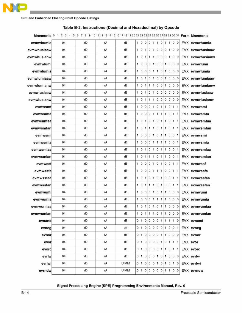
SPE and Embedded Floating-Point Opcode Listings
Signal Processing Engine (SPE) Programming Environments Manual, Rev. 0
B-14 Freescale Semiconductor
evmwhumia 04 rD rA rB 1 0 0 0 1 1 0 1 1 0 0 EVX evmwhumia
evmwhusiaaw 04 rD rA rB 1 0 1 0 1 0 0 0 1 0 0 EVX evmwhusiaaw
evmwhusianw 04 rD rA rB 1 0 1 1 1 0 0 0 1 0 0 EVX evmwhusianw
evmwlumi 04 rD rA rB 1 0 0 0 1 0 0 1 0 0 0 EVX evmwlumi
evmwlumia 04 rD rA rB 1 0 0 0 1 1 0 1 0 0 0 EVX evmwlumia
evmwlumiaaw 04 rD rA rB 1 0 1 0 1 0 0 1 0 0 0 EVX evmwlumiaaw
evmwlumianw 04 rD rA rB 1 0 1 1 1 0 0 1 0 0 0 EVX evmwlumianw
evmwlusiaaw 04 rD rA rB 1 0 1 0 1 0 0 0 0 0 0 EVX evmwlusiaaw
evmwlusianw 04 rD rA rB 1 0 1 1 1 0 0 0 0 0 0 EVX evmwlusianw
evmwsmf 04 rD rA rB 1 0 0 0 1 0 1 1 0 1 1 EVX evmwsmf
evmwsmfa 04 rD rA rB 1 0 0 0 1 1 1 1 0 1 1 EVX evmwsmfa
evmwsmfaa 04 rD rA rB 1 0 1 0 1 0 1 1 0 1 1 EVX evmwsmfaa
evmwsmfan 04 rD rA rB 1 0 1 1 1 0 1 1 0 1 1 EVX evmwsmfan
evmwsmi 04 rD rA rB 1 0 0 0 1 0 1 1 0 0 1 EVX evmwsmi
evmwsmia 04 rD rA rB 1 0 0 0 1 1 1 1 0 0 1 EVX evmwsmia
evmwsmiaa 04 rD rA rB 1 0 1 0 1 0 1 1 0 0 1 EVX evmwsmiaa
evmwsmian 04 rD rA rB 1 0 1 1 1 0 1 1 0 0 1 EVX evmwsmian
evmwssf 04 rD rA rB 1 0 0 0 1 0 1 0 0 1 1 EVX evmwssf
evmwssfa 04 rD rA rB 1 0 0 0 1 1 1 0 0 1 1 EVX evmwssfa
evmwssfaa 04 rD rA rB 1 0 1 0 1 0 1 0 0 1 1 EVX evmwssfaa
evmwssfan 04 rD rA rB 1 0 1 1 1 0 1 0 0 1 1 EVX evmwssfan
evmwumi 04 rD rA rB 1 0 0 0 1 0 1 1 0 0 0 EVX evmwumi
evmwumia 04 rD rA rB 1 0 0 0 1 1 1 1 0 0 0 EVX evmwumia
evmwumiaa 04 rD rA rB 1 0 1 0 1 0 1 1 0 0 0 EVX evmwumiaa
evmwumian 04 rD rA rB 1 0 1 1 1 0 1 1 0 0 0 EVX evmwumian
evnand 04 rD rA rB 0 1 0 0 0 0 1 1 1 1 0 EVX evnand
evneg 04 rD rA /// 0 1 0 0 0 0 0 1 0 0 1 EVX evneg
evnor 04 rD rA rB 0 1 0 0 0 0 1 1 0 0 0 EVX evnor
evor 04 rD rA rB 0 1 0 0 0 0 1 0 1 1 1 EVX evor
evorc 04 rD rA rB 0 1 0 0 0 0 1 1 0 1 1 EVX evorc
evrlw 04 rD rA rB 0 1 0 0 0 1 0 1 0 0 0 EVX evrlw
evrlwi 04 rD rA UIMM 0 1 0 0 0 1 0 1 0 1 0 EVX evrlwi
evrndw 04 rD rA UIMM 0 1 0 0 0 0 0 1 1 0 0 EVX evrndw
Table B-2. Instructions (Decimal and Hexadecimal) by Opcode
Mnemonic 0 1 2 3 4 5 6 7 8 9 10 11 12 13 14 15 16 17 18 19 20 21 22 23 24 25 26 27 28 29 30 31 Form Mnemonic
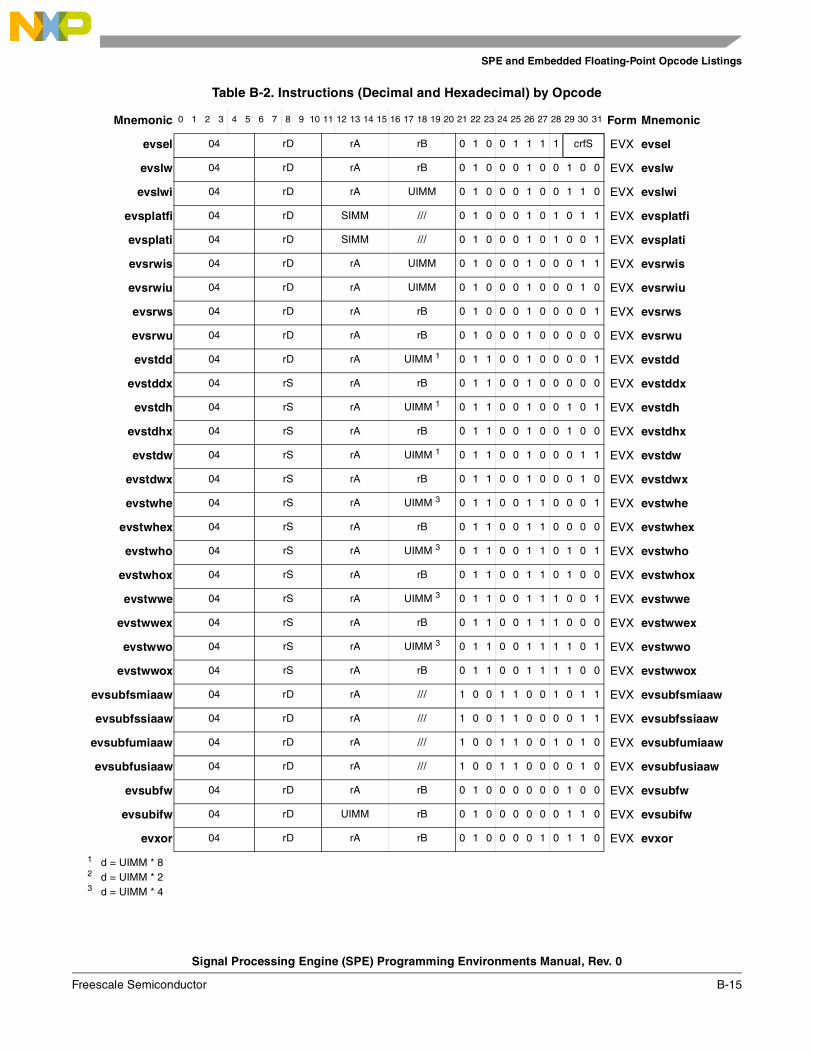
SPE and Embedded Floating-Point Opcode Listings
Signal Processing Engine (SPE) Programming Environments Manual, Rev. 0
Freescale Semiconductor B-15
evsel 04 rD rA rB 0 1 0 0 1 1 1 1 crfS EVX evsel
evslw 04 rD rA rB 0 1 0 0 0 1 0 0 1 0 0 EVX evslw
evslwi 04 rD rA UIMM 0 1 0 0 0 1 0 0 1 1 0 EVX evslwi
evsplatfi 04 rD SIMM /// 0 1 0 0 0 1 0 1 0 1 1 EVX evsplatfi
evsplati 04 rD SIMM /// 0 1 0 0 0 1 0 1 0 0 1 EVX evsplati
evsrwis 04 rD rA UIMM 0 1 0 0 0 1 0 0 0 1 1 EVX evsrwis
evsrwiu 04 rD rA UIMM 0 1 0 0 0 1 0 0 0 1 0 EVX evsrwiu
evsrws 04 rD rA rB 0 1 0 0 0 1 0 0 0 0 1 EVX evsrws
evsrwu 04 rD rA rB 0 1 0 0 0 1 0 0 0 0 0 EVX evsrwu
evstdd 04 rD rA UIMM 1 0 1 1 0 0 1 0 0 0 0 1 EVX evstdd
evstddx 04 rS rA rB 0 1 1 0 0 1 0 0 0 0 0 EVX evstddx
evstdh 04 rS rA UIMM 1 0 1 1 0 0 1 0 0 1 0 1 EVX evstdh
evstdhx 04 rS rA rB 0 1 1 0 0 1 0 0 1 0 0 EVX evstdhx
evstdw 04 rS rA UIMM 1 0 1 1 0 0 1 0 0 0 1 1 EVX evstdw
evstdwx 04 rS rA rB 0 1 1 0 0 1 0 0 0 1 0 EVX evstdwx
evstwhe 04 rS rA UIMM 3 0 1 1 0 0 1 1 0 0 0 1 EVX evstwhe
evstwhex 04 rS rA rB 0 1 1 0 0 1 1 0 0 0 0 EVX evstwhex
evstwho 04 rS rA UIMM 3 0 1 1 0 0 1 1 0 1 0 1 EVX evstwho
evstwhox 04 rS rA rB 0 1 1 0 0 1 1 0 1 0 0 EVX evstwhox
evstwwe 04 rS rA UIMM 3 0 1 1 0 0 1 1 1 0 0 1 EVX evstwwe
evstwwex 04 rS rA rB 0 1 1 0 0 1 1 1 0 0 0 EVX evstwwex
evstwwo 04 rS rA UIMM 3 0 1 1 0 0 1 1 1 1 0 1 EVX evstwwo
evstwwox 04 rS rA rB 0 1 1 0 0 1 1 1 1 0 0 EVX evstwwox
evsubfsmiaaw 04 rD rA /// 1 0 0 1 1 0 0 1 0 1 1 EVX evsubfsmiaaw
evsubfssiaaw 04 rD rA /// 1 0 0 1 1 0 0 0 0 1 1 EVX evsubfssiaaw
evsubfumiaaw 04 rD rA /// 1 0 0 1 1 0 0 1 0 1 0 EVX evsubfumiaaw
evsubfusiaaw 04 rD rA /// 1 0 0 1 1 0 0 0 0 1 0 EVX evsubfusiaaw
evsubfw 04 rD rA rB 0 1 0 0 0 0 0 0 1 0 0 EVX evsubfw
evsubifw 04 rD UIMM rB 0 1 0 0 0 0 0 0 1 1 0 EVX evsubifw
evxor 04 rD rA rB 0 1 0 0 0 0 1 0 1 1 0 EVX evxor
1 d = UIMM * 82 d = UIMM * 23 d = UIMM * 4
Table B-2. Instructions (Decimal and Hexadecimal) by Opcode
Mnemonic 0 1 2 3 4 5 6 7 8 9 10 11 12 13 14 15 16 17 18 19 20 21 22 23 24 25 26 27 28 29 30 31 Form Mnemonic
SPE and Embedded Floating-Point Opcode Listings
Signal Processing Engine (SPE) Programming Environments Manual, Rev. 0
B-16 Freescale Semiconductor
B.3 Instructions by FormTable B-3 lists instructions by form.
Table B-3. Instructions (Binary) by Form
Mnemonic 0 1 2 3 4 5 6 7 8 9 10 11 12 13 14 15 16 17 18 19 20 21 22 23 24 25 26 27 28 29 30 31 Form Mnemonic
efdabs 0 0 0 1 0 0 rD rA /// 0 1 0 1 1 1 0 0 1 0 0 EFX efdabs
efdadd 0 0 0 1 0 0 rD rA rB 0 1 0 1 1 1 0 0 0 0 0 EFX efdadd
efdcfs 0 0 0 1 0 0 rD 0 0 0 0 0 rB 0 1 0 1 1 1 0 1 1 1 1 EFX efdcfs
efdcfsf 0 0 0 1 0 0 rD /// rB 0 1 0 1 1 1 1 0 0 1 1 EFX efdcfsf
efdcfsi 0 0 0 1 0 0 rD /// rB 0 1 0 1 1 1 1 0 0 0 1 EFX efdcfsi
efdcfuf 0 0 0 1 0 0 rD /// rB 0 1 0 1 1 1 1 0 0 1 0 EFX efdcfuf
efdcfui 0 0 0 1 0 0 rD /// rB 0 1 0 1 1 1 1 0 0 0 0 EFX efdcfui
efdcmpeq 0 0 0 1 0 0 crfD / / rA rB 0 1 0 1 1 1 0 1 1 1 0 EFX efdcmpeq
efdcmpgt 0 0 0 1 0 0 crfD / / rA rB 0 1 0 1 1 1 0 1 1 0 0 EFX efdcmpgt
efdcmplt 0 0 0 1 0 0 crfD / / rA rB 0 1 0 1 1 1 0 1 1 0 1 EFX efdcmplt
efdctsf 0 0 0 1 0 0 rD /// rB 0 1 0 1 1 1 1 0 1 1 1 EFX efdctsf
efdctsi 0 0 0 1 0 0 rD /// rB 0 1 0 1 1 1 1 0 1 0 1 EFX efdctsi
efdctsiz 0 0 0 1 0 0 rD /// rB 0 1 0 1 1 1 1 1 0 1 0 EFX efdctsiz
efdctuf 0 0 0 1 0 0 rD /// rB 0 1 0 1 1 1 1 0 1 1 0 EFX efdctuf
efdctui 0 0 0 1 0 0 rD /// rB 0 1 0 1 1 1 1 0 1 0 0 EFX efdctui
efdctuiz 0 0 0 1 0 0 rD /// rB 0 1 0 1 1 1 1 1 0 0 0 EFX efdctuiz
efddiv 0 0 0 1 0 0 rD rA rB 0 1 0 1 1 1 0 1 0 0 1 EFX efddiv
efdmul 0 0 0 1 0 0 rD rA rB 0 1 0 1 1 1 0 1 0 0 0 EFX efdmul
efdnabs 0 0 0 1 0 0 rD rA /// 0 1 0 1 1 1 0 0 1 0 1 EFX efdnabs
efdneg 0 0 0 1 0 0 rD rA /// 0 1 0 1 1 1 0 0 1 1 0 EFX efdneg
efdsub 0 0 0 1 0 0 rD rA rB 0 1 0 1 1 1 0 0 0 0 1 EFX efdsub
efdtsteq 0 0 0 1 0 0 crfD / / rA rB 0 1 0 1 1 1 1 1 1 1 0 EFX efdtsteq
efdtstgt 0 0 0 1 0 0 crfD / / rA rB 0 1 0 1 1 1 1 1 1 0 0 EFX efdtstgt
efdtstlt 0 0 0 1 0 0 crfD / / rA rB 0 1 0 1 1 1 1 1 1 0 1 EFX efdtstlt
efsabs 0 0 0 1 0 0 rD rA /// 0 1 0 1 1 0 0 0 1 0 0 EFX efsabs
efsadd 0 0 0 1 0 0 rD rA rB 0 1 0 1 1 0 0 0 0 0 0 EFX efsadd
efscfd 0 0 0 1 0 0 rD 0 0 0 0 0 rB 0 1 0 1 1 0 0 1 1 1 1 EFX efscfd
efscfsf 0 0 0 1 0 0 rD /// rB 0 1 0 1 1 0 1 0 0 1 1 EFX efscfsf
efscfsi 0 0 0 1 0 0 rD /// rB 0 1 0 1 1 0 1 0 0 0 1 EFX efscfsi
efscfuf 0 0 0 1 0 0 rD /// rB 0 1 0 1 1 0 1 0 0 1 0 EFX efscfuf
SPE and Embedded Floating-Point Opcode Listings
Signal Processing Engine (SPE) Programming Environments Manual, Rev. 0
Freescale Semiconductor B-17
efscfui 0 0 0 1 0 0 rD /// rB 0 1 0 1 1 0 1 0 0 0 0 EFX efscfui
efscmpeq 0 0 0 1 0 0 crfD / / rA rB 0 1 0 1 1 0 0 1 1 1 0 EFX efscmpeq
efscmpgt 0 0 0 1 0 0 crfD / / rA rB 0 1 0 1 1 0 0 1 1 0 0 EFX efscmpgt
efscmplt 0 0 0 1 0 0 crfD / / rA rB 0 1 0 1 1 0 0 1 1 0 1 EFX efscmplt
efsctsf 0 0 0 1 0 0 rD /// rB 0 1 0 1 1 0 1 0 1 1 1 EFX efsctsf
efsctsi 0 0 0 1 0 0 rD /// rB 0 1 0 1 1 0 1 0 1 0 1 EFX efsctsi
efsctsiz 0 0 0 1 0 0 rD /// rB 0 1 0 1 1 0 1 1 0 1 0 EFX efsctsiz
efsctuf 0 0 0 1 0 0 rD /// rB 0 1 0 1 1 0 1 0 1 1 0 EFX efsctuf
efsctui 0 0 0 1 0 0 rD /// rB 0 1 0 1 1 0 1 0 1 0 0 EFX efsctui
efsctuiz 0 0 0 1 0 0 rD /// rB 0 1 0 1 1 0 1 1 0 0 0 EFX efsctuiz
efsdiv 0 0 0 1 0 0 rD rA rB 0 1 0 1 1 0 0 1 0 0 1 EFX efsdiv
efsmul 0 0 0 1 0 0 rD rA rB 0 1 0 1 1 0 0 1 0 0 0 EFX efsmul
efsnabs 0 0 0 1 0 0 rD rA /// 0 1 0 1 1 0 0 0 1 0 1 EFX efsnabs
efsneg 0 0 0 1 0 0 rD rA /// 0 1 0 1 1 0 0 0 1 1 0 EFX efsneg
efssub 0 0 0 1 0 0 rD rA rB 0 1 0 1 1 0 0 0 0 0 1 EFX efssub
efststeq 0 0 0 1 0 0 crfD / / rA rB 0 1 0 1 1 0 1 1 1 1 0 EFX efststeq
efststgt 0 0 0 1 0 0 crfD / / rA rB 0 1 0 1 1 0 1 1 1 0 0 EFX efststgt
efststlt 0 0 0 1 0 0 crfD / / rA rB 0 1 0 1 1 0 1 1 1 0 1 EFX efststlt
brinc1 0 0 0 1 0 0 rD rA rB 0 1 0 0 0 0 0 1 1 1 1 EVX brinc
evabs 0 0 0 1 0 0 rD rA /// 0 1 0 0 0 0 0 1 0 0 0 EVX evabs
evaddiw 0 0 0 1 0 0 rD UIMM rB 0 1 0 0 0 0 0 0 0 1 0 EVX evaddiw
evaddsmiaaw 0 0 0 1 0 0 rD rA /// 1 0 0 1 1 0 0 1 0 0 1 EVX evaddsmiaaw
evaddssiaaw 0 0 0 1 0 0 rD rA /// 1 0 0 1 1 0 0 0 0 0 1 EVX evaddssiaaw
evaddumiaaw 0 0 0 1 0 0 rD rA /// 1 0 0 1 1 0 0 1 0 0 0 EVX evaddumiaaw
evaddusiaaw 0 0 0 1 0 0 rD rA /// 1 0 0 1 1 0 0 0 0 0 0 EVX evaddusiaaw
evaddw 0 0 0 1 0 0 rD rA rB 0 1 0 0 0 0 0 0 0 0 0 EVX evaddw
evand 0 0 0 1 0 0 rD rA rB 0 1 0 0 0 0 1 0 0 0 1 EVX evand
evandc 0 0 0 1 0 0 rD rA rB 0 1 0 0 0 0 1 0 0 1 0 EVX evandc
evcmpeq 0 0 0 1 0 0 crfD / / rA rB 0 1 0 0 0 1 1 0 1 0 0 EVX evcmpeq
evcmpgts 0 0 0 1 0 0 crfD / / rA rB 0 1 0 0 0 1 1 0 0 0 1 EVX evcmpgts
evcmpgtu 0 0 0 1 0 0 crfD / / rA rB 0 1 0 0 0 1 1 0 0 0 0 EVX evcmpgtu
evcmplts 0 0 0 1 0 0 crfD / / rA rB 0 1 0 0 0 1 1 0 0 1 1 EVX evcmplts
evcmpltu 0 0 0 1 0 0 crfD / / rA rB 0 1 0 0 0 1 1 0 0 1 0 EVX evcmpltu
Table B-3. Instructions (Binary) by Form
Mnemonic 0 1 2 3 4 5 6 7 8 9 10 11 12 13 14 15 16 17 18 19 20 21 22 23 24 25 26 27 28 29 30 31 Form Mnemonic
SPE and Embedded Floating-Point Opcode Listings
Signal Processing Engine (SPE) Programming Environments Manual, Rev. 0
B-18 Freescale Semiconductor
evcntlsw 0 0 0 1 0 0 rD rA /// 0 1 0 0 0 0 0 1 1 1 0 EVX evcntlsw
evcntlzw 0 0 0 1 0 0 rD rA /// 0 1 0 0 0 0 0 1 1 0 1 EVX evcntlzw
evdivws 0 0 0 1 0 0 rD rA rB 1 0 0 1 1 0 0 0 1 1 0 EVX evdivws
evdivwu 0 0 0 1 0 0 rD rA rB 1 0 0 1 1 0 0 0 1 1 1 EVX evdivwu
eveqv 0 0 0 1 0 0 rD rA rB 0 1 0 0 0 0 1 1 0 0 1 EVX eveqv
evextsb 0 0 0 1 0 0 rD rA /// 0 1 0 0 0 0 0 1 0 1 0 EVX evextsb
evextsh 0 0 0 1 0 0 rD rA /// 0 1 0 0 0 0 0 1 0 1 1 EVX evextsh
evfsabs 0 0 0 1 0 0 rD rA /// 0 1 0 1 0 0 0 0 1 0 0 EVX evfsabs
evfsadd 0 0 0 1 0 0 rD rA rB 0 1 0 1 0 0 0 0 0 0 0 EVX evfsadd
evfscfsf 0 0 0 1 0 0 rD /// rB 0 1 0 1 0 0 1 0 0 1 1 EVX evfscfsf
evfscfsi 0 0 0 1 0 0 rD /// rB 0 1 0 1 0 0 1 0 0 0 1 EVX evfscfsi
evfscfuf 0 0 0 1 0 0 rD /// rB 0 1 0 1 0 0 1 0 0 1 0 EVX evfscfuf
evfscfui 0 0 0 1 0 0 rD /// rB 0 1 0 1 0 0 1 0 0 0 0 EVX evfscfui
evfscmpeq 0 0 0 1 0 0 crfD / / rA rB 0 1 0 1 0 0 0 1 1 1 0 EVX evfscmpeq
evfscmpgt 0 0 0 1 0 0 crfD / / rA rB 0 1 0 1 0 0 0 1 1 0 0 EVX evfscmpgt
evfscmplt 0 0 0 1 0 0 crfD / / rA rB 0 1 0 1 0 0 0 1 1 0 1 EVX evfscmplt
evfsctsf 0 0 0 1 0 0 rD /// rB 0 1 0 1 0 0 1 0 1 1 1 EVX evfsctsf
evfsctsi 0 0 0 1 0 0 rD /// rB 0 1 0 1 0 0 1 0 1 0 1 EVX evfsctsi
evfsctsiz 0 0 0 1 0 0 rD /// rB 0 1 0 1 0 0 1 1 0 1 0 EVX evfsctsiz
evfsctuf 0 0 0 1 0 0 rD /// rB 0 1 0 1 0 0 1 0 1 1 0 EVX evfsctuf
evfsctui 0 0 0 1 0 0 rD /// rB 0 1 0 1 0 0 1 0 1 0 0 EVX evfsctui
evfsctuiz 0 0 0 1 0 0 rD /// rB 0 1 0 1 0 0 1 1 0 0 0 EVX evfsctuiz
evfsdiv 0 0 0 1 0 0 rD rA rB 0 1 0 1 0 0 0 1 0 0 1 EVX evfsdiv
evfsmul 0 0 0 1 0 0 rD rA rB 0 1 0 1 0 0 0 1 0 0 0 EVX evfsmul
evfsnabs 0 0 0 1 0 0 rD rA /// 0 1 0 1 0 0 0 0 1 0 1 EVX evfsnabs
evfsneg 0 0 0 1 0 0 rD rA /// 0 1 0 1 0 0 0 0 1 1 0 EVX evfsneg
evfssub 0 0 0 1 0 0 rD rA rB 0 1 0 1 0 0 0 0 0 0 1 EVX evfssub
evfststeq 0 0 0 1 0 0 crfD / / rA rB 0 1 0 1 0 0 1 1 1 1 0 EVX evfststeq
evfststgt 0 0 0 1 0 0 crfD / / rA rB 0 1 0 1 0 0 1 1 1 0 0 EVX evfststgt
evfststlt 0 0 0 1 0 0 crfD / / rA rB 0 1 0 1 0 0 1 1 1 0 1 EVX evfststlt
evldd 0 0 0 1 0 0 rD rA UIMM1 0 1 1 0 0 0 0 0 0 0 1 EVX evldd
evlddx 0 0 0 1 0 0 rD rA rB 0 1 1 0 0 0 0 0 0 0 0 EVX evlddx
evldh 0 0 0 1 0 0 rD rA UIMM 1 0 1 1 0 0 0 0 0 1 0 1 EVX evldh
Table B-3. Instructions (Binary) by Form
Mnemonic 0 1 2 3 4 5 6 7 8 9 10 11 12 13 14 15 16 17 18 19 20 21 22 23 24 25 26 27 28 29 30 31 Form Mnemonic
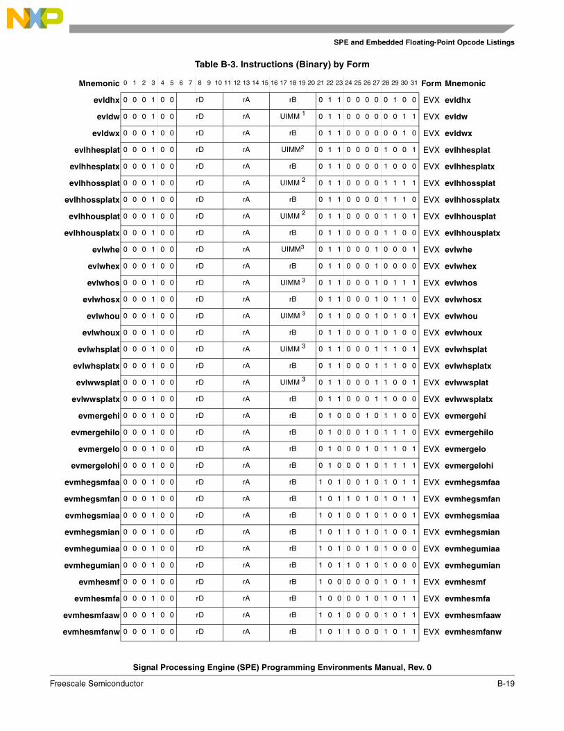
SPE and Embedded Floating-Point Opcode Listings
Signal Processing Engine (SPE) Programming Environments Manual, Rev. 0
Freescale Semiconductor B-19
evldhx 0 0 0 1 0 0 rD rA rB 0 1 1 0 0 0 0 0 1 0 0 EVX evldhx
evldw 0 0 0 1 0 0 rD rA UIMM 1 0 1 1 0 0 0 0 0 0 1 1 EVX evldw
evldwx 0 0 0 1 0 0 rD rA rB 0 1 1 0 0 0 0 0 0 1 0 EVX evldwx
evlhhesplat 0 0 0 1 0 0 rD rA UIMM2 0 1 1 0 0 0 0 1 0 0 1 EVX evlhhesplat
evlhhesplatx 0 0 0 1 0 0 rD rA rB 0 1 1 0 0 0 0 1 0 0 0 EVX evlhhesplatx
evlhhossplat 0 0 0 1 0 0 rD rA UIMM 2 0 1 1 0 0 0 0 1 1 1 1 EVX evlhhossplat
evlhhossplatx 0 0 0 1 0 0 rD rA rB 0 1 1 0 0 0 0 1 1 1 0 EVX evlhhossplatx
evlhhousplat 0 0 0 1 0 0 rD rA UIMM 2 0 1 1 0 0 0 0 1 1 0 1 EVX evlhhousplat
evlhhousplatx 0 0 0 1 0 0 rD rA rB 0 1 1 0 0 0 0 1 1 0 0 EVX evlhhousplatx
evlwhe 0 0 0 1 0 0 rD rA UIMM3 0 1 1 0 0 0 1 0 0 0 1 EVX evlwhe
evlwhex 0 0 0 1 0 0 rD rA rB 0 1 1 0 0 0 1 0 0 0 0 EVX evlwhex
evlwhos 0 0 0 1 0 0 rD rA UIMM 3 0 1 1 0 0 0 1 0 1 1 1 EVX evlwhos
evlwhosx 0 0 0 1 0 0 rD rA rB 0 1 1 0 0 0 1 0 1 1 0 EVX evlwhosx
evlwhou 0 0 0 1 0 0 rD rA UIMM 3 0 1 1 0 0 0 1 0 1 0 1 EVX evlwhou
evlwhoux 0 0 0 1 0 0 rD rA rB 0 1 1 0 0 0 1 0 1 0 0 EVX evlwhoux
evlwhsplat 0 0 0 1 0 0 rD rA UIMM 3 0 1 1 0 0 0 1 1 1 0 1 EVX evlwhsplat
evlwhsplatx 0 0 0 1 0 0 rD rA rB 0 1 1 0 0 0 1 1 1 0 0 EVX evlwhsplatx
evlwwsplat 0 0 0 1 0 0 rD rA UIMM 3 0 1 1 0 0 0 1 1 0 0 1 EVX evlwwsplat
evlwwsplatx 0 0 0 1 0 0 rD rA rB 0 1 1 0 0 0 1 1 0 0 0 EVX evlwwsplatx
evmergehi 0 0 0 1 0 0 rD rA rB 0 1 0 0 0 1 0 1 1 0 0 EVX evmergehi
evmergehilo 0 0 0 1 0 0 rD rA rB 0 1 0 0 0 1 0 1 1 1 0 EVX evmergehilo
evmergelo 0 0 0 1 0 0 rD rA rB 0 1 0 0 0 1 0 1 1 0 1 EVX evmergelo
evmergelohi 0 0 0 1 0 0 rD rA rB 0 1 0 0 0 1 0 1 1 1 1 EVX evmergelohi
evmhegsmfaa 0 0 0 1 0 0 rD rA rB 1 0 1 0 0 1 0 1 0 1 1 EVX evmhegsmfaa
evmhegsmfan 0 0 0 1 0 0 rD rA rB 1 0 1 1 0 1 0 1 0 1 1 EVX evmhegsmfan
evmhegsmiaa 0 0 0 1 0 0 rD rA rB 1 0 1 0 0 1 0 1 0 0 1 EVX evmhegsmiaa
evmhegsmian 0 0 0 1 0 0 rD rA rB 1 0 1 1 0 1 0 1 0 0 1 EVX evmhegsmian
evmhegumiaa 0 0 0 1 0 0 rD rA rB 1 0 1 0 0 1 0 1 0 0 0 EVX evmhegumiaa
evmhegumian 0 0 0 1 0 0 rD rA rB 1 0 1 1 0 1 0 1 0 0 0 EVX evmhegumian
evmhesmf 0 0 0 1 0 0 rD rA rB 1 0 0 0 0 0 0 1 0 1 1 EVX evmhesmf
evmhesmfa 0 0 0 1 0 0 rD rA rB 1 0 0 0 0 1 0 1 0 1 1 EVX evmhesmfa
evmhesmfaaw 0 0 0 1 0 0 rD rA rB 1 0 1 0 0 0 0 1 0 1 1 EVX evmhesmfaaw
evmhesmfanw 0 0 0 1 0 0 rD rA rB 1 0 1 1 0 0 0 1 0 1 1 EVX evmhesmfanw
Table B-3. Instructions (Binary) by Form
Mnemonic 0 1 2 3 4 5 6 7 8 9 10 11 12 13 14 15 16 17 18 19 20 21 22 23 24 25 26 27 28 29 30 31 Form Mnemonic
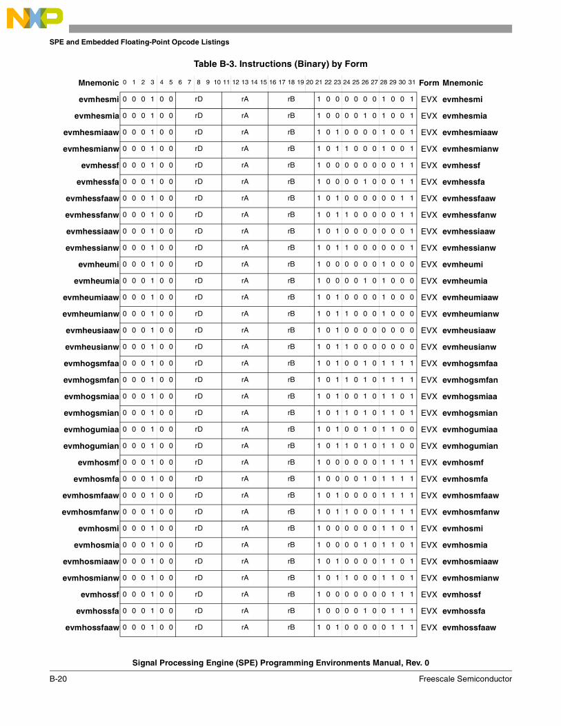
SPE and Embedded Floating-Point Opcode Listings
Signal Processing Engine (SPE) Programming Environments Manual, Rev. 0
B-20 Freescale Semiconductor
evmhesmi 0 0 0 1 0 0 rD rA rB 1 0 0 0 0 0 0 1 0 0 1 EVX evmhesmi
evmhesmia 0 0 0 1 0 0 rD rA rB 1 0 0 0 0 1 0 1 0 0 1 EVX evmhesmia
evmhesmiaaw 0 0 0 1 0 0 rD rA rB 1 0 1 0 0 0 0 1 0 0 1 EVX evmhesmiaaw
evmhesmianw 0 0 0 1 0 0 rD rA rB 1 0 1 1 0 0 0 1 0 0 1 EVX evmhesmianw
evmhessf 0 0 0 1 0 0 rD rA rB 1 0 0 0 0 0 0 0 0 1 1 EVX evmhessf
evmhessfa 0 0 0 1 0 0 rD rA rB 1 0 0 0 0 1 0 0 0 1 1 EVX evmhessfa
evmhessfaaw 0 0 0 1 0 0 rD rA rB 1 0 1 0 0 0 0 0 0 1 1 EVX evmhessfaaw
evmhessfanw 0 0 0 1 0 0 rD rA rB 1 0 1 1 0 0 0 0 0 1 1 EVX evmhessfanw
evmhessiaaw 0 0 0 1 0 0 rD rA rB 1 0 1 0 0 0 0 0 0 0 1 EVX evmhessiaaw
evmhessianw 0 0 0 1 0 0 rD rA rB 1 0 1 1 0 0 0 0 0 0 1 EVX evmhessianw
evmheumi 0 0 0 1 0 0 rD rA rB 1 0 0 0 0 0 0 1 0 0 0 EVX evmheumi
evmheumia 0 0 0 1 0 0 rD rA rB 1 0 0 0 0 1 0 1 0 0 0 EVX evmheumia
evmheumiaaw 0 0 0 1 0 0 rD rA rB 1 0 1 0 0 0 0 1 0 0 0 EVX evmheumiaaw
evmheumianw 0 0 0 1 0 0 rD rA rB 1 0 1 1 0 0 0 1 0 0 0 EVX evmheumianw
evmheusiaaw 0 0 0 1 0 0 rD rA rB 1 0 1 0 0 0 0 0 0 0 0 EVX evmheusiaaw
evmheusianw 0 0 0 1 0 0 rD rA rB 1 0 1 1 0 0 0 0 0 0 0 EVX evmheusianw
evmhogsmfaa 0 0 0 1 0 0 rD rA rB 1 0 1 0 0 1 0 1 1 1 1 EVX evmhogsmfaa
evmhogsmfan 0 0 0 1 0 0 rD rA rB 1 0 1 1 0 1 0 1 1 1 1 EVX evmhogsmfan
evmhogsmiaa 0 0 0 1 0 0 rD rA rB 1 0 1 0 0 1 0 1 1 0 1 EVX evmhogsmiaa
evmhogsmian 0 0 0 1 0 0 rD rA rB 1 0 1 1 0 1 0 1 1 0 1 EVX evmhogsmian
evmhogumiaa 0 0 0 1 0 0 rD rA rB 1 0 1 0 0 1 0 1 1 0 0 EVX evmhogumiaa
evmhogumian 0 0 0 1 0 0 rD rA rB 1 0 1 1 0 1 0 1 1 0 0 EVX evmhogumian
evmhosmf 0 0 0 1 0 0 rD rA rB 1 0 0 0 0 0 0 1 1 1 1 EVX evmhosmf
evmhosmfa 0 0 0 1 0 0 rD rA rB 1 0 0 0 0 1 0 1 1 1 1 EVX evmhosmfa
evmhosmfaaw 0 0 0 1 0 0 rD rA rB 1 0 1 0 0 0 0 1 1 1 1 EVX evmhosmfaaw
evmhosmfanw 0 0 0 1 0 0 rD rA rB 1 0 1 1 0 0 0 1 1 1 1 EVX evmhosmfanw
evmhosmi 0 0 0 1 0 0 rD rA rB 1 0 0 0 0 0 0 1 1 0 1 EVX evmhosmi
evmhosmia 0 0 0 1 0 0 rD rA rB 1 0 0 0 0 1 0 1 1 0 1 EVX evmhosmia
evmhosmiaaw 0 0 0 1 0 0 rD rA rB 1 0 1 0 0 0 0 1 1 0 1 EVX evmhosmiaaw
evmhosmianw 0 0 0 1 0 0 rD rA rB 1 0 1 1 0 0 0 1 1 0 1 EVX evmhosmianw
evmhossf 0 0 0 1 0 0 rD rA rB 1 0 0 0 0 0 0 0 1 1 1 EVX evmhossf
evmhossfa 0 0 0 1 0 0 rD rA rB 1 0 0 0 0 1 0 0 1 1 1 EVX evmhossfa
evmhossfaaw 0 0 0 1 0 0 rD rA rB 1 0 1 0 0 0 0 0 1 1 1 EVX evmhossfaaw
Table B-3. Instructions (Binary) by Form
Mnemonic 0 1 2 3 4 5 6 7 8 9 10 11 12 13 14 15 16 17 18 19 20 21 22 23 24 25 26 27 28 29 30 31 Form Mnemonic
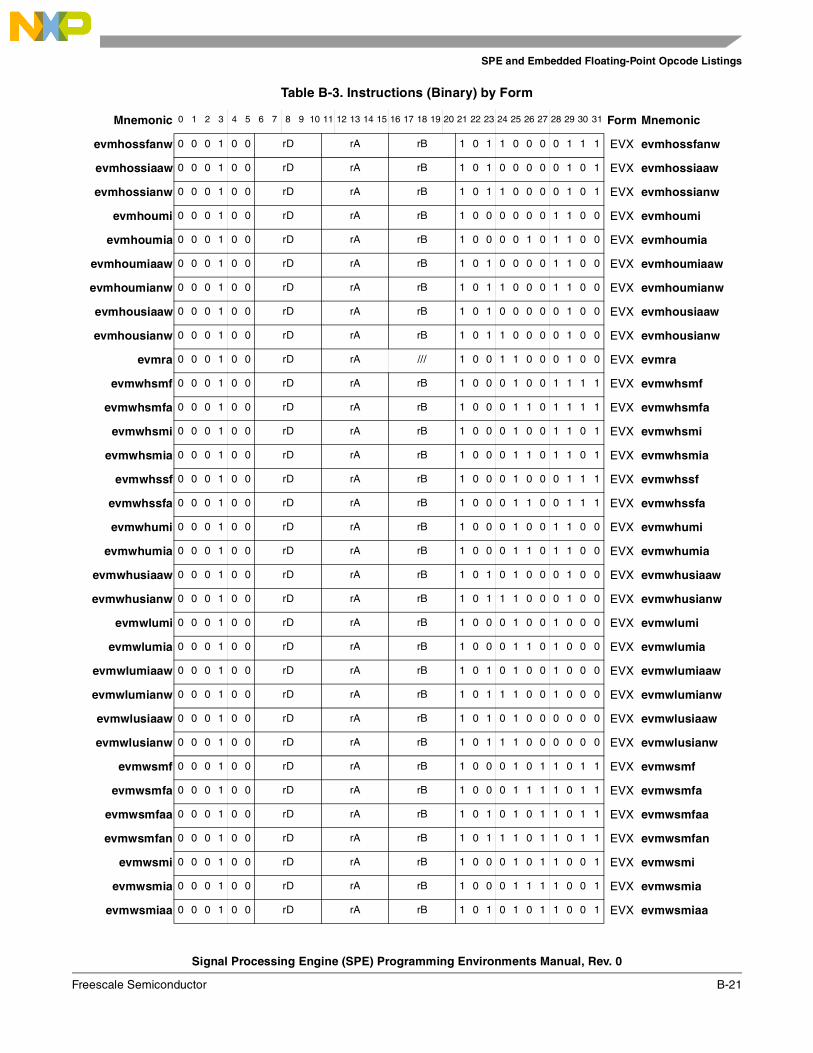
SPE and Embedded Floating-Point Opcode Listings
Signal Processing Engine (SPE) Programming Environments Manual, Rev. 0
Freescale Semiconductor B-21
evmhossfanw 0 0 0 1 0 0 rD rA rB 1 0 1 1 0 0 0 0 1 1 1 EVX evmhossfanw
evmhossiaaw 0 0 0 1 0 0 rD rA rB 1 0 1 0 0 0 0 0 1 0 1 EVX evmhossiaaw
evmhossianw 0 0 0 1 0 0 rD rA rB 1 0 1 1 0 0 0 0 1 0 1 EVX evmhossianw
evmhoumi 0 0 0 1 0 0 rD rA rB 1 0 0 0 0 0 0 1 1 0 0 EVX evmhoumi
evmhoumia 0 0 0 1 0 0 rD rA rB 1 0 0 0 0 1 0 1 1 0 0 EVX evmhoumia
evmhoumiaaw 0 0 0 1 0 0 rD rA rB 1 0 1 0 0 0 0 1 1 0 0 EVX evmhoumiaaw
evmhoumianw 0 0 0 1 0 0 rD rA rB 1 0 1 1 0 0 0 1 1 0 0 EVX evmhoumianw
evmhousiaaw 0 0 0 1 0 0 rD rA rB 1 0 1 0 0 0 0 0 1 0 0 EVX evmhousiaaw
evmhousianw 0 0 0 1 0 0 rD rA rB 1 0 1 1 0 0 0 0 1 0 0 EVX evmhousianw
evmra 0 0 0 1 0 0 rD rA /// 1 0 0 1 1 0 0 0 1 0 0 EVX evmra
evmwhsmf 0 0 0 1 0 0 rD rA rB 1 0 0 0 1 0 0 1 1 1 1 EVX evmwhsmf
evmwhsmfa 0 0 0 1 0 0 rD rA rB 1 0 0 0 1 1 0 1 1 1 1 EVX evmwhsmfa
evmwhsmi 0 0 0 1 0 0 rD rA rB 1 0 0 0 1 0 0 1 1 0 1 EVX evmwhsmi
evmwhsmia 0 0 0 1 0 0 rD rA rB 1 0 0 0 1 1 0 1 1 0 1 EVX evmwhsmia
evmwhssf 0 0 0 1 0 0 rD rA rB 1 0 0 0 1 0 0 0 1 1 1 EVX evmwhssf
evmwhssfa 0 0 0 1 0 0 rD rA rB 1 0 0 0 1 1 0 0 1 1 1 EVX evmwhssfa
evmwhumi 0 0 0 1 0 0 rD rA rB 1 0 0 0 1 0 0 1 1 0 0 EVX evmwhumi
evmwhumia 0 0 0 1 0 0 rD rA rB 1 0 0 0 1 1 0 1 1 0 0 EVX evmwhumia
evmwhusiaaw 0 0 0 1 0 0 rD rA rB 1 0 1 0 1 0 0 0 1 0 0 EVX evmwhusiaaw
evmwhusianw 0 0 0 1 0 0 rD rA rB 1 0 1 1 1 0 0 0 1 0 0 EVX evmwhusianw
evmwlumi 0 0 0 1 0 0 rD rA rB 1 0 0 0 1 0 0 1 0 0 0 EVX evmwlumi
evmwlumia 0 0 0 1 0 0 rD rA rB 1 0 0 0 1 1 0 1 0 0 0 EVX evmwlumia
evmwlumiaaw 0 0 0 1 0 0 rD rA rB 1 0 1 0 1 0 0 1 0 0 0 EVX evmwlumiaaw
evmwlumianw 0 0 0 1 0 0 rD rA rB 1 0 1 1 1 0 0 1 0 0 0 EVX evmwlumianw
evmwlusiaaw 0 0 0 1 0 0 rD rA rB 1 0 1 0 1 0 0 0 0 0 0 EVX evmwlusiaaw
evmwlusianw 0 0 0 1 0 0 rD rA rB 1 0 1 1 1 0 0 0 0 0 0 EVX evmwlusianw
evmwsmf 0 0 0 1 0 0 rD rA rB 1 0 0 0 1 0 1 1 0 1 1 EVX evmwsmf
evmwsmfa 0 0 0 1 0 0 rD rA rB 1 0 0 0 1 1 1 1 0 1 1 EVX evmwsmfa
evmwsmfaa 0 0 0 1 0 0 rD rA rB 1 0 1 0 1 0 1 1 0 1 1 EVX evmwsmfaa
evmwsmfan 0 0 0 1 0 0 rD rA rB 1 0 1 1 1 0 1 1 0 1 1 EVX evmwsmfan
evmwsmi 0 0 0 1 0 0 rD rA rB 1 0 0 0 1 0 1 1 0 0 1 EVX evmwsmi
evmwsmia 0 0 0 1 0 0 rD rA rB 1 0 0 0 1 1 1 1 0 0 1 EVX evmwsmia
evmwsmiaa 0 0 0 1 0 0 rD rA rB 1 0 1 0 1 0 1 1 0 0 1 EVX evmwsmiaa
Table B-3. Instructions (Binary) by Form
Mnemonic 0 1 2 3 4 5 6 7 8 9 10 11 12 13 14 15 16 17 18 19 20 21 22 23 24 25 26 27 28 29 30 31 Form Mnemonic
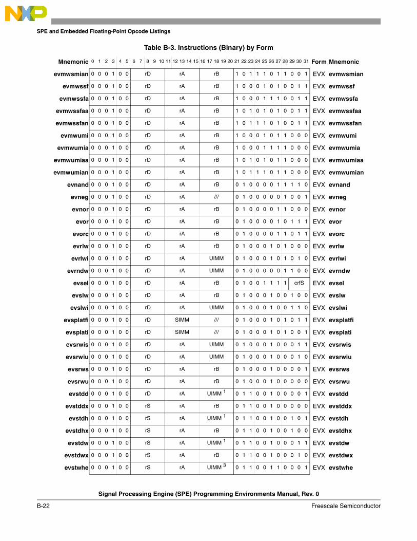
SPE and Embedded Floating-Point Opcode Listings
Signal Processing Engine (SPE) Programming Environments Manual, Rev. 0
B-22 Freescale Semiconductor
evmwsmian 0 0 0 1 0 0 rD rA rB 1 0 1 1 1 0 1 1 0 0 1 EVX evmwsmian
evmwssf 0 0 0 1 0 0 rD rA rB 1 0 0 0 1 0 1 0 0 1 1 EVX evmwssf
evmwssfa 0 0 0 1 0 0 rD rA rB 1 0 0 0 1 1 1 0 0 1 1 EVX evmwssfa
evmwssfaa 0 0 0 1 0 0 rD rA rB 1 0 1 0 1 0 1 0 0 1 1 EVX evmwssfaa
evmwssfan 0 0 0 1 0 0 rD rA rB 1 0 1 1 1 0 1 0 0 1 1 EVX evmwssfan
evmwumi 0 0 0 1 0 0 rD rA rB 1 0 0 0 1 0 1 1 0 0 0 EVX evmwumi
evmwumia 0 0 0 1 0 0 rD rA rB 1 0 0 0 1 1 1 1 0 0 0 EVX evmwumia
evmwumiaa 0 0 0 1 0 0 rD rA rB 1 0 1 0 1 0 1 1 0 0 0 EVX evmwumiaa
evmwumian 0 0 0 1 0 0 rD rA rB 1 0 1 1 1 0 1 1 0 0 0 EVX evmwumian
evnand 0 0 0 1 0 0 rD rA rB 0 1 0 0 0 0 1 1 1 1 0 EVX evnand
evneg 0 0 0 1 0 0 rD rA /// 0 1 0 0 0 0 0 1 0 0 1 EVX evneg
evnor 0 0 0 1 0 0 rD rA rB 0 1 0 0 0 0 1 1 0 0 0 EVX evnor
evor 0 0 0 1 0 0 rD rA rB 0 1 0 0 0 0 1 0 1 1 1 EVX evor
evorc 0 0 0 1 0 0 rD rA rB 0 1 0 0 0 0 1 1 0 1 1 EVX evorc
evrlw 0 0 0 1 0 0 rD rA rB 0 1 0 0 0 1 0 1 0 0 0 EVX evrlw
evrlwi 0 0 0 1 0 0 rD rA UIMM 0 1 0 0 0 1 0 1 0 1 0 EVX evrlwi
evrndw 0 0 0 1 0 0 rD rA UIMM 0 1 0 0 0 0 0 1 1 0 0 EVX evrndw
evsel 0 0 0 1 0 0 rD rA rB 0 1 0 0 1 1 1 1 crfS EVX evsel
evslw 0 0 0 1 0 0 rD rA rB 0 1 0 0 0 1 0 0 1 0 0 EVX evslw
evslwi 0 0 0 1 0 0 rD rA UIMM 0 1 0 0 0 1 0 0 1 1 0 EVX evslwi
evsplatfi 0 0 0 1 0 0 rD SIMM /// 0 1 0 0 0 1 0 1 0 1 1 EVX evsplatfi
evsplati 0 0 0 1 0 0 rD SIMM /// 0 1 0 0 0 1 0 1 0 0 1 EVX evsplati
evsrwis 0 0 0 1 0 0 rD rA UIMM 0 1 0 0 0 1 0 0 0 1 1 EVX evsrwis
evsrwiu 0 0 0 1 0 0 rD rA UIMM 0 1 0 0 0 1 0 0 0 1 0 EVX evsrwiu
evsrws 0 0 0 1 0 0 rD rA rB 0 1 0 0 0 1 0 0 0 0 1 EVX evsrws
evsrwu 0 0 0 1 0 0 rD rA rB 0 1 0 0 0 1 0 0 0 0 0 EVX evsrwu
evstdd 0 0 0 1 0 0 rD rA UIMM 1 0 1 1 0 0 1 0 0 0 0 1 EVX evstdd
evstddx 0 0 0 1 0 0 rS rA rB 0 1 1 0 0 1 0 0 0 0 0 EVX evstddx
evstdh 0 0 0 1 0 0 rS rA UIMM 1 0 1 1 0 0 1 0 0 1 0 1 EVX evstdh
evstdhx 0 0 0 1 0 0 rS rA rB 0 1 1 0 0 1 0 0 1 0 0 EVX evstdhx
evstdw 0 0 0 1 0 0 rS rA UIMM 1 0 1 1 0 0 1 0 0 0 1 1 EVX evstdw
evstdwx 0 0 0 1 0 0 rS rA rB 0 1 1 0 0 1 0 0 0 1 0 EVX evstdwx
evstwhe 0 0 0 1 0 0 rS rA UIMM 3 0 1 1 0 0 1 1 0 0 0 1 EVX evstwhe
Table B-3. Instructions (Binary) by Form
Mnemonic 0 1 2 3 4 5 6 7 8 9 10 11 12 13 14 15 16 17 18 19 20 21 22 23 24 25 26 27 28 29 30 31 Form Mnemonic
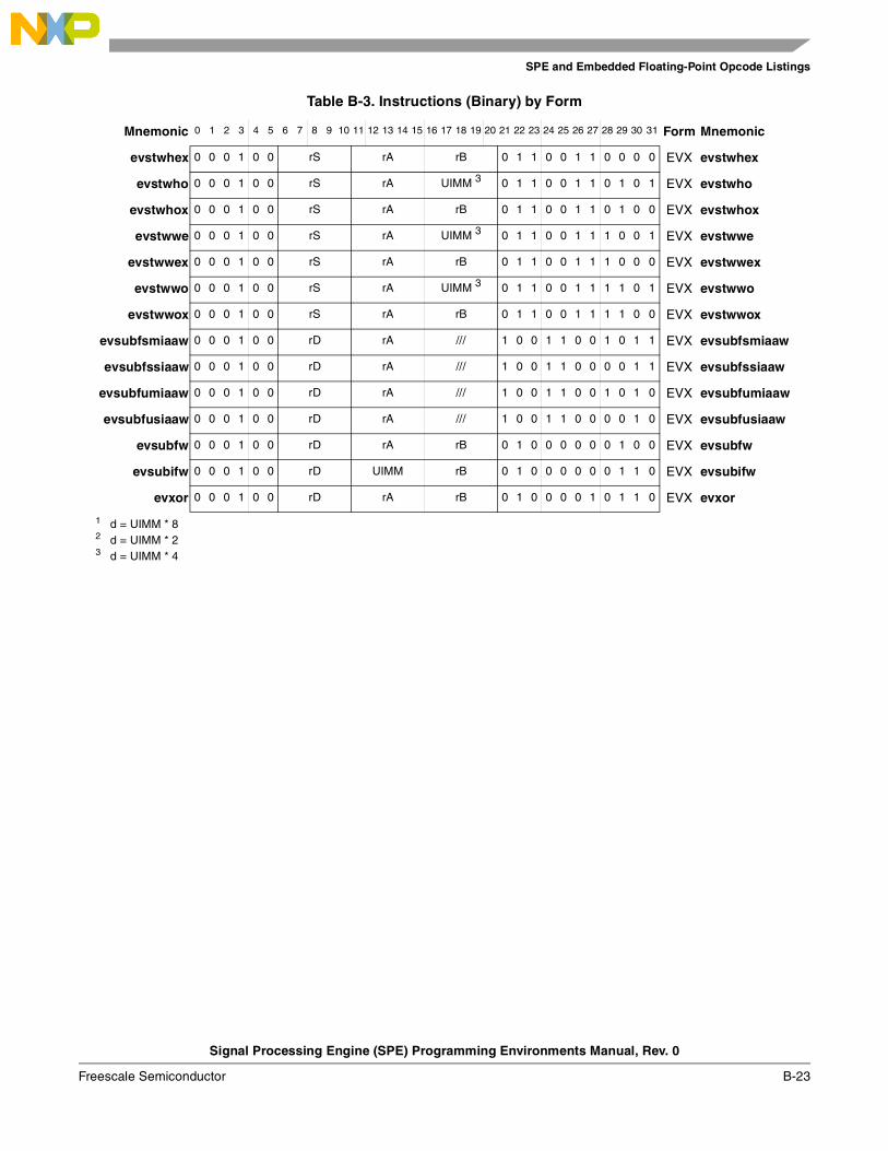
SPE and Embedded Floating-Point Opcode Listings
Signal Processing Engine (SPE) Programming Environments Manual, Rev. 0
Freescale Semiconductor B-23
evstwhex 0 0 0 1 0 0 rS rA rB 0 1 1 0 0 1 1 0 0 0 0 EVX evstwhex
evstwho 0 0 0 1 0 0 rS rA UIMM 3 0 1 1 0 0 1 1 0 1 0 1 EVX evstwho
evstwhox 0 0 0 1 0 0 rS rA rB 0 1 1 0 0 1 1 0 1 0 0 EVX evstwhox
evstwwe 0 0 0 1 0 0 rS rA UIMM 3 0 1 1 0 0 1 1 1 0 0 1 EVX evstwwe
evstwwex 0 0 0 1 0 0 rS rA rB 0 1 1 0 0 1 1 1 0 0 0 EVX evstwwex
evstwwo 0 0 0 1 0 0 rS rA UIMM 3 0 1 1 0 0 1 1 1 1 0 1 EVX evstwwo
evstwwox 0 0 0 1 0 0 rS rA rB 0 1 1 0 0 1 1 1 1 0 0 EVX evstwwox
evsubfsmiaaw 0 0 0 1 0 0 rD rA /// 1 0 0 1 1 0 0 1 0 1 1 EVX evsubfsmiaaw
evsubfssiaaw 0 0 0 1 0 0 rD rA /// 1 0 0 1 1 0 0 0 0 1 1 EVX evsubfssiaaw
evsubfumiaaw 0 0 0 1 0 0 rD rA /// 1 0 0 1 1 0 0 1 0 1 0 EVX evsubfumiaaw
evsubfusiaaw 0 0 0 1 0 0 rD rA /// 1 0 0 1 1 0 0 0 0 1 0 EVX evsubfusiaaw
evsubfw 0 0 0 1 0 0 rD rA rB 0 1 0 0 0 0 0 0 1 0 0 EVX evsubfw
evsubifw 0 0 0 1 0 0 rD UIMM rB 0 1 0 0 0 0 0 0 1 1 0 EVX evsubifw
evxor 0 0 0 1 0 0 rD rA rB 0 1 0 0 0 0 1 0 1 1 0 EVX evxor
1 d = UIMM * 82 d = UIMM * 23 d = UIMM * 4
Table B-3. Instructions (Binary) by Form
Mnemonic 0 1 2 3 4 5 6 7 8 9 10 11 12 13 14 15 16 17 18 19 20 21 22 23 24 25 26 27 28 29 30 31 Form Mnemonic

SPE and Embedded Floating-Point Opcode Listings
Signal Processing Engine (SPE) Programming Environments Manual, Rev. 0
B-24 Freescale Semiconductor