signal design data collection office data collection base
TRANSCRIPT

MARYLAND STATE HIGHWAY ADMINISTRATION
Office of Traffic and Safety Traffic Engineering Design Division
Traffic Control Devices Design Manual
45 July 2006
SIGNAL DESIGN
DATA COLLECTION
Office data collection is the first step in designing a signal. Collecting data, base mapping (obtaining or developing a base plan) and field review apply to both individual intersection design and signal systems. This is the time when the designer gathers information, collects existing data from outside sources, visits the project site and looks at potential design options, .
Office Data Collection Before preparing a design, the Designer should collect preliminary data and research existing records to develop the base plan and subsequently proceed with a conceptual design. For example, the Designer must research SHA files for as-built plans, highway design plans, right-of-way plats and utility plans. Although all of the as-built information may not be available or completely accurate, the Designer shall do this research to gain information on the history of the location. The designer could also check with the District for existing plans.
The District office generally initiates the Design Request (DR) for a traffic signal design project, and thus may have some background information on the project, including a traffic study, traffic counts or recommendations on the proposed operation of the signal. The designer should have a clear understanding of the project and contact the preparer of the DR for further information.
Another element for collecting office data is any proposed work being done. If the project is an insert job to a highway project, then the proposed geometrics and area improvements should be obtained. This may be acquired through the SHA lead division or perhaps a local authority. This information is essential to ensure a constructible design.
Base Plan The base plan is a key to the field work and design of a traffic signal. It must be accurate and able to be used as a base for construction. In order to
properly design a signal, the designer needs a base plan showing existing topography, roadway geometrics, pavement markings, utilities, etc. The base plan should be in electronic format. The best place to start is with the TEDD files (on MDS). Often there may be an existing electronic file with this information that can then be field verified. The designer should verify within TEDD that the obtained plan is the latest version. For an insert job the electronic base plan may be obtained from the lead division, usually Highway Division. Other options may include a professional survey or extensive field work to obtain all of the mapping information.
Information to Collect Initial Site Visit Most of the necessary information should be obtained during the initial site visit. This is the time to collect new information, verify existing information and prepare for the proposed signal design.
1. Collect existing information. This should include at a minimum:
• Existing signal – If there is an existing signal then the configurations, type of cabinet, controller, detection, signal structures, signal heads, etc. should all be gathered to be included with the plans. Determine what may be reused and what needs to be replaced.
• Road geometrics (including lane configuration, turn bay lengths, lane widths, open vs. closed section)
• Drainage elements (structures and ditches) • Roadway alignment, vertical and horizontal • Pavement markings • Signing • Sidewalks and handicap ramps • Driveways and entrances • Utilities (overhead and underground) • On street parking • Buildings and setback • Trees and vegetation
2. Begin to prepare conceptual locations for the proposed signal. Check and see which quadrants may or may not suit the cabinet or signal structures. Locate potential power feeds
MARYLAND STATE HIGHWAY ADMINISTRATION
Office of Traffic and Safety Traffic Engineering Design Division
Traffic Control Devices Design Manual
46 July 2006
and telephone lines for service. Identify if there are any constraints for laying conduit and placing handholes.
3. Locate and measure the heights of overhead utilities, particularly at potential conflict locations. This will allow for meeting the NESC and the Maryland High Voltage-line Act requirements of utility clearance and avoiding any conflicts between the proposed signal and existing utilities. These measurements shall be documented and shown on the signal plan in areas that will have crossings with signal equipment.
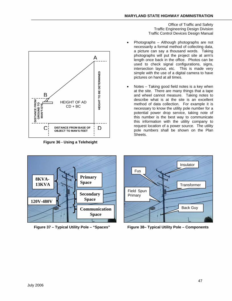
It is important to make note of any fuses, transformers, splice boxes or insulators on the utility pole. This will help in identifying what type of lines are on the pole. For instance, generally fuses are located between primary distribution lines and a transformer. The secondary (power feed) lines are usually located directly below the transformer. Also, a splice box on lower lines is typically an indication of telephone lines. See Figure 36 on the following page.
4. Open and check handholes and conduit if new wiring will be necessary to verify if existing conduits can be used. Make note of existing wire in conduits so the conduit fill capacity is not exceeded with new wire.
5. Always take photographs while in the field. This may save another trip to the site. These should be supplied to SHA with the electronic plan for future use.
Subsequent Site Visits For most projects it will be necessary to do at least one subsequent site visit. This should include the verification of all proposed work. Things may change frequently without prior notice so it is important to verify that the design is constructible and optimal for the given location.
Field Data Collection Methods The limits of the site review on each approach are usually determined by the location of advance signing, placement of detectors, signal system limits and length of turn bays. The methods used to collect field information may vary from a
professional survey to simple tape and wheel techniques. The method will also vary dependent of the information required. Some of the following methodologies are explained further.
• Professional Survey – A professional survey is the hiring of an outside company or SHA survey forces to collect the field information and mapping. A professional topographically survey may be needed on a case-by-case basis. This is the most accurate, all encompassing method to collect field data, but is typically the most expensive and time consuming.
• Tape and Wheel – The designer or designated person does a tape and wheel survey. This is the simple method of visiting the project site and using tape measures, wheels or other measuring devices to collect critical information. Using this method information may be collected on lane widths, lane lengths, pole size, locations and sizes of structures, sign sizes, etc. The data collected shall be documented.
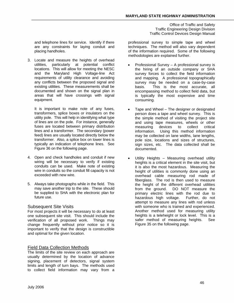
• Utility Heights – Measuring overhead utility heights is a critical element in the site visit, but it is also the most hazardous. Measuring the height of utilities is commonly done using an overhead cable measuring rod made of fiberglass. The rod is then used to measure the height of the different overhead utilities from the ground. DO NOT measure the primary electric lines with the rod due to hazardous high voltage. Further, do not attempt to measure any lines with rod unless with someone who is trained and experienced. Another method used for measuring utility heights is a teleheight or lock level. This is a safer method of measuring heights. See Figure 35 on the following page.
MARYLAND STATE HIGHWAY ADMINISTRATION
Office of Traffic and Safety Traffic Engineering Design Division
Traffic Control Devices Design Manual
47 July 2006
Figure 36 - Using a Teleheight
• Photographs – Although photographs are not necessarily a formal method of collecting data, a picture can say a thousand words. Taking photographs will put the project site at arm's length once back in the office. Photos can be used to check signal configurations, signs, intersection layout, etc. This is made very simple with the use of a digital camera to have pictures on hand at all times.
• Notes – Taking good field notes is a key when at the site. There are many things that a tape and wheel cannot measure. Taking notes to describe what is at the site is an excellent method of data collection. For example it is necessary to know the utility pole number for a potential power drop service, taking note of this number is the best way to communicate this information with the utility company to request location of a power source. The utility pole numbers shall be shown on the Plan Sheets.
Figure 37 – Typical Utility Pole – “Spaces” Figure 38– Typical Utility Pole – Components
A
DDISTANCE FROM BASE OF OBJECT TO MAN’S FEET C
HEI
GH
T TO
BE
DET
ERM
INED
B
DIS
TAN
CE
FRO
M
GR
OU
ND
TO
M
AN
’ S E
YE HEIGHT OF AD
CD + BC
Transformer
Fus
Field Spun Primary
Insulator
Back Guy
Primary Space
Secondary Space
Communication Space
8KVA- 13KVA
120V-480V
MARYLAND STATE HIGHWAY ADMINISTRATION
Office of Traffic and Safety Traffic Engineering Design Division
Traffic Control Devices Design Manual
48 July 2006
CONCEPTUAL PLANS
Developing a Concept The conceptual plan is developed before the final signal plan is designed. A concept shall be developed for both individual signalized intersections and signal systems. The designer will develop what he feels is the desired layout prior to completing a design. This conceptual design sets the foundation for the signal design. It is the first milestone in which input is received from the parties involved including the designer, team leader and district traffic office at a minimum.
The goal of the conceptual plan is to put on paper what the designer feels is the desired configuration of the major signal components including the poles, cabinet and signal heads. The focus should be on the type of signal structures to be used, which quadrant will best suit the cabinet, how the signal heads should be configured, what type of detection should be used and are there any special design considerations such as a hazard identification beacon (HIB), intersection control beacon (ICB), signal preemption, etc. It is also important to ensure that an existing signal will remain operational during all proposed construction.
The Major Signal Components
Book of Standards References
Signal Structure Foundations
Strain Poles, Mast Arm Poles, Pedestal Poles, and Anchor Bolts Details
Pedestal Poles and Transformer Base
Traffic signals are designed to operate as a system with the signing and pavement markings. The major signal components reviewed at the conceptual stage include signal structures (type, configuration and placement), controller cabinet (type and location), signal heads (number and placement) and detection (operation and technology)
Signal Structures
Type of Supports There are several types of signal supports that may be used on a project. The decision of which type of structure to use is based on several factors, including location of overhead utilities, intersection geometrics, proposed location of traffic signal heads, aesthetics and local requirements. Consideration to surrounding signal types shall also be conducted. Overall there are 6 types of signal supports. They are
1. Mast Arm (Preferred option)
2. Strain Pole
3. Pedestal Pole
4. Wood Pole Supports (Temporary signals only)
5. Bridge Mount
6. Special “T” Dimension Mast Arms For Avoiding Utility Conflicts
Mast Arms Mast arm supports are generally preferred because the signal heads are more rigidly held in place. In addition, they may reduce the number of poles and minimize conflicts with overhead utilities. Mast arm supports shall be used for rigid support of optically programmed signal heads, overhead hazard identification beacons (HIB) and overhead advance warning signs, also reference the MD SHA Book of Standards.
Strain Poles At some locations, strain poles with span wires are required for proper signal placements. For example, at wide intersections, mast arms may not be long enough to place signal heads in the proper location for optimum visibility.
Pedestal Poles Pedestal poles are primarily used for mounting pedestrian signal heads, HIBs and left-turn signals in the median of divided highways. Some other situations when pedestal poles may be used for signal heads includes locations where buildings are very close to the road, when overhead utility conflicts exist or for aesthetic purposes in historic areas. Pedestal poles are generally 10 feet long (for pedestrian signals) or 14 or 20 feet long for
MARYLAND STATE HIGHWAY ADMINISTRATION
Office of Traffic and Safety Traffic Engineering Design Division
Traffic Control Devices Design Manual
49 July 2006
other applications. They can typically support two 12-inch, pedestrian signal heads or three-section vehicular heads.
Wood Poles Wood poles are not typically used for permanent signal design. Wood poles are most commonly used for temporary signals to be included with a Maintenance of Traffic Plan.
Bridge Mounted Supports Bridge mounted supports are not typically used for permanent signal design. In order to use this application, SHA Bridge Design Division must approve it.
Special “T” Dimension Mast Arm Special “T” mast arms provide the same benefits as standard mast arms but have a modified design such that the mast arm has a bend and is mounted to the pole at 15 feet rather than 18 feet. These are used to avoid utility conflicts.
MARYLAND STATE HIGHWAY ADMINISTRATION
Office of Traffic and Safety Traffic Engineering Design Division
Traffic Control Devices Design Manual
50 July 2006
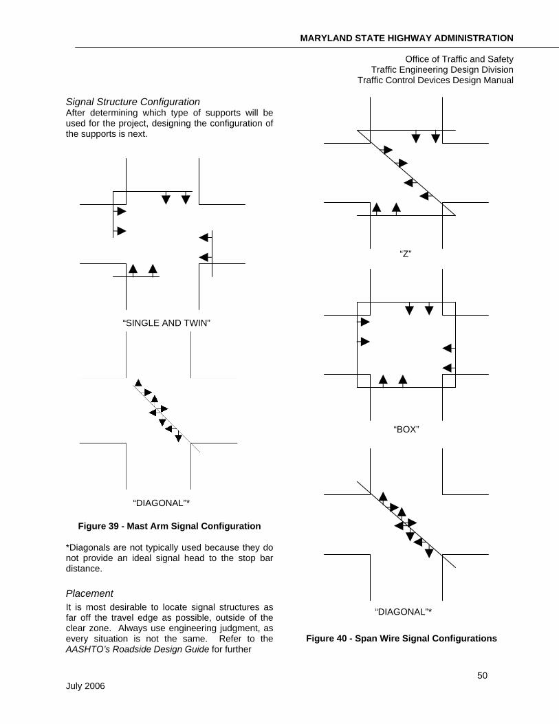
Signal Structure Configuration After determining which type of supports will be used for the project, designing the configuration of the supports is next.
Figure 39 - Mast Arm Signal Configuration
*Diagonals are not typically used because they do not provide an ideal signal head to the stop bar distance.
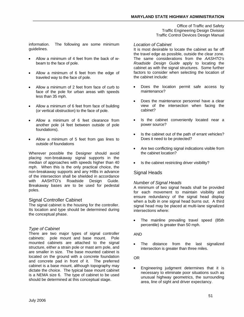
Placement It is most desirable to locate signal structures as far off the travel edge as possible, outside of the clear zone. Always use engineering judgment, as every situation is not the same. Refer to the AASHTO’s Roadside Design Guide for further
Figure 40 - Span Wire Signal Configurations
“Z”
“BOX”
“DIAGONAL”*
“SINGLE AND TWIN”
“DIAGONAL”*
MARYLAND STATE HIGHWAY ADMINISTRATION
Office of Traffic and Safety Traffic Engineering Design Division
Traffic Control Devices Design Manual
51 July 2006
information. The following are some minimum guidelines.
• Allow a minimum of 4 feet from the back of w-beam to the face of pole.
• Allow a minimum of 6 feet from the edge of traveled way to the face of pole.
• Allow a minimum of 2 feet from face of curb to face of the pole for urban areas with speeds less than 35 mph.
• Allow a minimum of 6 feet from face of building (or vertical obstruction) to the face of pole.
• Allow a minimum of 6 feet clearance from another pole (4 feet between outside of pole foundations).
• Allow a minimum of 5 feet from gas lines to outside of foundations
Wherever possible the Designer should avoid placing non-breakaway signal supports in the median of approaches with speeds higher than 40 mph. When this is the only practical choice, the non-breakaway supports and any HIBs in advance of the intersection shall be shielded in accordance with AASHTO’s Roadside Design Guide. Breakaway bases are to be used for pedestal poles.
Signal Controller Cabinet The signal cabinet is the housing for the controller. Its location and type should be determined during the conceptual phase.
Type of Cabinet There are two major types of signal controller cabinets: pole mount and base mount. Pole mounted cabinets are attached to the signal structure, either a strain pole or mast arm pole, and are smaller in size. The base mounted cabinet is located on the ground with a concrete foundation and concrete pad in front of it. The preferred cabinet is a base mount, although topography may dictate the choice. The typical base mount cabinet is a NEMA size 6. The type of cabinet to be used should be determined at this conceptual stage.
Location of Cabinet It is most desirable to locate the cabinet as far off the travel edge as possible, outside the clear zone. The same considerations from the AASHTO’s Roadside Design Guide apply to locating the cabinet as with the signal structures. Some further factors to consider when selecting the location of the cabinet include:
• Does the location permit safe access by maintenance?
• Does the maintenance personnel have a clear view of the intersection when facing the cabinet?
• Is the cabinet conveniently located near a power source?
• Is the cabinet out of the path of errant vehicles? Does it need to be protected?
• Are two conflicting signal indications visible from the cabinet location?
• Is the cabinet restricting driver visibility?
Signal Heads
Number of Signal Heads A minimum of two signal heads shall be provided for each movement to maintain visibility and ensure redundancy of the signal head display when a bulb in one signal head burns out. A third signal head may be placed at multi-lane signalized intersections where:
• The mainline prevailing travel speed (85th percentile) is greater than 50 mph.
AND
• The distance from the last signalized intersection is greater than three miles.
OR
• Engineering judgment determines that it is necessary to eliminate poor situations such as unusual highway geometrics, the surrounding area, line of sight and driver expectancy.
MARYLAND STATE HIGHWAY ADMINISTRATION
Office of Traffic and Safety Traffic Engineering Design Division
Traffic Control Devices Design Manual
52 July 2006
Signal Head Placement The bottom of the signal head housing (overhead signals) should be at least 17 feet and not more than 19 feet above the high point of the roadway.
The horizontal placement may vary with the type of display on the approach. The primary concern when placing signal heads is visibility. Refer to Section 4D.15 in the MUTCD for a complete discussion of this topic. Table 4D-1 from the MUTCD provides minimum visibility distances for signal heads. The Designer should check the roadway horizontal alignment, vertical alignment and any potential obstructions, such as buildings, walls, etc. when selecting the proper placement for traffic signal indications.
The MUTCD lists several criteria that should be considered when locating signal heads. Some of these guidelines that will determine the placement of the signal heads are as follows:
• Two signal heads shall be provided for each phase at an intersection.
• At least one and preferably both of the signal heads shall be placed not less than 40’ nor more than 150’ from the stop line.
• At least one and preferably both of the signal heads shall be placed within 20 degrees to the right or left of the center of the approach lanes.
• A near-side signal head should be provided when the distance from the stop line to one or more far-side signal heads is more than 120’.
• A near-side signal head should be provided when there are unusual roadway geometrics, 3 or more thru lanes, or when the horizontal or vertical alignment of the roadway limits the minimum visibility distance requirements.
• An exclusive movement, with a double left turn lane, shall have two far-side signal heads. A supplemental near-side signal head or far left signal head shall also be used.
• An exclusive or exclusive/permissive left-turn movement, with a single turn lane, requires a near-side and far-side signal head.
• A side street split phase requires a near-side signal.
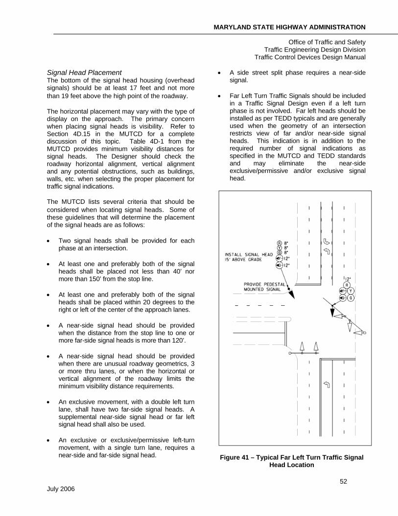
• Far Left Turn Traffic Signals should be included in a Traffic Signal Design even if a left turn phase is not involved. Far left heads should be installed as per TEDD typicals and are generally used when the geometry of an intersection restricts view of far and/or near-side signal heads. This indication is in addition to the required number of signal indications as specified in the MUTCD and TEDD standards and may eliminate the near-side exclusive/permissive and/or exclusive signal head.
Figure 41 – Typical Far Left Turn Traffic Signal Head Location
MARYLAND STATE HIGHWAY ADMINISTRATION
Office of Traffic and Safety Traffic Engineering Design Division
Traffic Control Devices Design Manual
53 July 2006
Signal Detection Detection allows a signal controller to know when vehicles are at an intersection. During the conceptual design the operation and technology to be used for the intersection should be determined. Most intersections in Maryland operate as fully actuated intersections and will receive detection.
Operation of the Detection Signal detection takes on two basic operational functions, presence and passage.
Presence Detection Presence detection indicates that a vehicle is in the detection zone. The presence detection has a setting of “nonlocking”. This means that the controller only knows if a vehicle is in the zone, once a vehicle leaves the detection zone the controller “forgets” it was ever there. These detectors are typically used on side streets and left turn bays at the stop line when it is critical to know if a vehicle is waiting for green. The preferred presence detection is video imaging detection; however, 6 feet x 30 feet inductive loops are also common especially at span signals.
Passage Detection Passage detection, also called point or pulse detection, indicates that a vehicle has gone through a detection zone and the memory of the vehicle is stored in the controller. The passage detection has a setting of “locking” in the controller and extends the green time for that movement. These detectors are typically used on mainlines and as system detection. The preferred passage detection is non-invasive microloop probes. In areas that right-of-way, geometrics, or underground utilities restrict the use of non-invasive probes, microloop probes would be the next choice for passage detection. Another option is to use 6 feet x 6 feet inductive loop detectors or video imaging cameras for passage detection.
Sampling Detection The preferred sampling detection is 6 feet x 6 feet inductive loop detectors. They provide more accurate presence and occupancy readings and shall be placed downstream of an intersection in a location that represents free flow of traffic.
Video Imaging Video imaging camera detectors are the preferred type of presence detection and can also be used for passage detection. Video cameras are placed on the signal mast arm or a lighting bracket arm attached to the signal pole. Their location and mounting height are dependent on the geometry of the intersection and obtaining an unobstructed field of view. Based on the location and distance of the camera from the desired detection area, the Field of View (FOV) can be calculated and the required lens can be determined.
Magneto-inductive Vehicle Sensor Magneto-inductive vehicle sensors are commonly known as Microloop probes. A microloop probe is a small cylindrical, passive transducer, which transforms the earth’s vertical magnetic field intensity into inductance. It transforms changes in magnetic field intensity into inductance changes that can be sensed by detector units. The Microloop probes are intended for passage detection applications and have the same application and placement as a 6’X6’ small area inductive loop. However, a microloop probe acts more like a point detector and provides very good resistance to detecting vehicles in adjacent lanes.
Non-invasive microloop probes are the preferred technology for SHA when using a simple passage detector. When used, the probes are installed in a seamless conduit under the roadway with handholes on each side of the road. They are placed 3 feet apart and 3 probes per lane. This type of detection is not in the pavement and will not be affected with roadway milling. In the event they go bad, the damaged probes can be pulled out and replaced with new ones in the same conduit.
Another method of installing microloop probes beneath the roadway surface is by drilling a 1-inch diameter hole (18-inch to 24-inch deep) in the pavement and inserting the probes. This method has a greater service life over 6’x6’ inductive loops due to the reduced exposure to hazards such as road traffic, pavement movement, pavement deterioration, and roadwork but do not offer the same repair efficiency as the non-invasive microloop probes.
MARYLAND STATE HIGHWAY ADMINISTRATION
Office of Traffic and Safety Traffic Engineering Design Division
Traffic Control Devices Design Manual
54 July 2006
Inductive Loops Inductive loop detectors are used for presence and passage detection. These loops are formed by sawcutting the roadway, placing a #14 AWG wire incased in flexible tubing in the sawcut and then sealing the sawcut. Typically it is carried into a handhole and spliced with an aluminum shielded wire that is carried back to the controller.
When used as a passage detector, typically a 6 feet x 6 feet loop is placed in advance of the intersection. SHA designs these loops by placing one 6’X6’ loop per travel lane. These loops are also used as a means of sampling and in Maryland most commonly used for system detectors.
Inductive loops used as presence detectors, typically 6 feet x 30 feet quadruple, are placed 1 ft behind the stop line on minor approaches and in left-turn lanes to detect and extend green time for the movement being served. These are also placed as one loop per travel lane. Large area “quadruple” type detectors require three sawcuts in the longitudinal direction and the loop wires are wrapped in a figure “8” pattern.
Large area detectors that serve exclusive right and left-turn lanes are timed with a delay output feature. This allows a detector call input to be delayed by the amplifier should a turning vehicle complete a turn within the delayed call timing. The delayed call timing is programmable in length of time by the amplifier.
Other Technologies In addition to video imaging, inductive loops and Microloop probes several other technologies are available for signal detection. Although they are not regularly used within the state of Maryland, some of these technologies include:
• Microwave
• Magnetic
• Magnetometer
• Infrared
• Light Emission
• Sonic
• Radar
These are not typically used on SHA projects unless special situations arise.
Special Design Considerations Some of the elements that may need special attention during the conceptual design are utility clearance, signal preemption, HIB, ICB, bikers, ADA requirements and pedestrians.
Utility Clearance Utility clearance is the required distance between utilities such as power, cable and telephone and signal equipment. The utility clearances also apply to signing and lighting. The utility clearance requirement may have an effect on the configuration of the signal structures and should be looked at from the very beginning.
The clearance distances from utility cables to signal structures and cables must comply with the latest requirements of the MD High Voltage Act, a pole owner (such as BGE) and National Electrical Safety Code (NESC). Typically, traffic signal equipment shall be at least 10 feet away from all primary electric lines, 4 feet from secondary lines and 2 feet away from telephone and cable television lines. The most current version of NESC shall be followed.
Signal Preemption Signal preemption is used to implement a special sequence or phase of signal indications by responding to an external command. Some of these applications include a firehouse, emergency vehicles and trains. The most common application in Maryland is for firehouse preemption.
When or if signal preemption is required should be determined in the conceptual design. This is usually included on the Design Request. The type of preemption to be used should also be determined. Firehouse preemption is usually designed through the use of an optically activated priority control system or hard wiring.
MARYLAND STATE HIGHWAY ADMINISTRATION
Office of Traffic and Safety Traffic Engineering Design Division
Traffic Control Devices Design Manual
55 July 2006
Optically Activated Priority Control System An optically activated priority control system is a system with an emitter and detector used for preemption. The emergency vehicle has an emitter mounted to it that produces pulses of high intensity light that is received by a detector located at the signal. The detector is usually located on top of a signal mast arm. After the detector receives the emission the message is sent back to the controller and the signal is preempted. This option is good for clear lines of visibility when the emergency vehicles travel a straight path to the signal. This eliminates the need for extensive wiring to a firehouse.
Hard Wire Hard wiring is running a direct wire from the signal controller directly into the firehouse. The firehouse is equipped with a pushbutton that is used when signal preemption is needed. This option is good when the firehouse is in close proximity to the signal and visibility may be limited. This is also the common application for rail preemption.
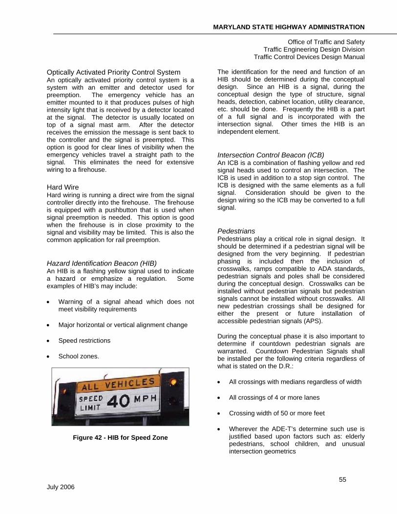
Hazard Identification Beacon (HIB) An HIB is a flashing yellow signal used to indicate a hazard or emphasize a regulation. Some examples of HIB’s may include:
• Warning of a signal ahead which does not meet visibility requirements
• Major horizontal or vertical alignment change
• Speed restrictions
• School zones.
Figure 42 - HIB for Speed Zone
The identification for the need and function of an HIB should be determined during the conceptual design. Since an HIB is a signal, during the conceptual design the type of structure, signal heads, detection, cabinet location, utility clearance, etc. should be done. Frequently the HIB is a part of a full signal and is incorporated with the intersection signal. Other times the HIB is an independent element.
Intersection Control Beacon (ICB) An ICB is a combination of flashing yellow and red signal heads used to control an intersection. The ICB is used in addition to a stop sign control. The ICB is designed with the same elements as a full signal. Consideration should be given to the design wiring so the ICB may be converted to a full signal.
Pedestrians Pedestrians play a critical role in signal design. It should be determined if a pedestrian signal will be designed from the very beginning. If pedestrian phasing is included then the inclusion of crosswalks, ramps compatible to ADA standards, pedestrian signals and poles shall be considered during the conceptual design. Crosswalks can be installed without pedestrian signals but pedestrian signals cannot be installed without crosswalks. All new pedestrian crossings shall be designed for either the present or future installation of accessible pedestrian signals (APS).
During the conceptual phase it is also important to determine if countdown pedestrian signals are warranted. Countdown Pedestrian Signals shall be installed per the following criteria regardless of what is stated on the D.R.:
• All crossings with medians regardless of width
• All crossings of 4 or more lanes
• Crossing width of 50 or more feet
• Wherever the ADE-T’s determine such use is justified based upon factors such as: elderly pedestrians, school children, and unusual intersection geometrics
MARYLAND STATE HIGHWAY ADMINISTRATION
Office of Traffic and Safety Traffic Engineering Design Division
Traffic Control Devices Design Manual
56 July 2006
Note that when emergency vehicle pre-emption is present at the signalized intersection, the use of countdown pedestrian signals should be evaluated and reviewed prior to design. This is to prevent pedestrians from receiving a false impression that they have more time to cross the street than the signal allows once a pre-emption call is placed to the controller.
Accessible Pedestrian Signals (APS) An APS is a device that communicates information about pedestrian timing in nonvisual formats such as audible tones, verbal messages, and/or vibrating surfaces. This also includes detectable warning surfaces or truncated domes. During conceptual design it is necessary to identify the potential demand and/or request for accessible pedestrian signals. In the SHA OHD Accessibility Policy & Guidelines for Pedestrian Facilities along State Highways, it states that “All projects, regardless of who is administering the contract, shall accommodate and provide accessibility for persons with disabilities where it is reasonable, feasible and appropriate to do so…..basically any time we do anything to the roadway that would or could improve pedestrian access.” Further, ADA ramps shall be provided in accordance to the functionality and requirements of the APS.
Signal Interconnect Signal interconnection is the connection of two or more signals to create a system using land-line communication. If a project is included with an existing interconnect or as part of a proposed interconnection, then it should be part of the conceptual design. The type of communication used should be identified as well as identifying the system as a whole. The proposed design with existing interconnect shall be designed to be constructed without causing down time to the interconnected system. This may require some temporary interconnect design to achieve.
Reviewing the Concept The conceptual plan is the time for all interested parties to agree and finalize the major decision making components of the signal design. At this point the designer should receive input from the District Traffic Office, the County Office or Local
Municipality and the OOTS representatives. This conceptual plan will govern the other elements of design to follow. Resolving any conflicts or issues at this point will eliminate the need for change after final design.
A reviewer should consider the following items when viewing a conceptual signal plan:
1. Check that the signal meets the requirements of the Design Request.
2. Check that the signal is not in conflict with any utilities.
3. Check for the power feed source.
4. Check for any special design considerations such as HIBs, pedestrians, preemption or interconnection.
5. Check that the signal will work as a system with the roadway, signing and marking.
6. Check for overall concurrence with Federal, MUTCD and SHA standards.
MARYLAND STATE HIGHWAY ADMINISTRATION
Office of Traffic and Safety Traffic Engineering Design Division
Traffic Control Devices Design Manual
57 July 2006
FINAL DESIGN
After the conceptual plan has been approved the design then moves to final design. Final design is the core of the project. This is finalizing layout, operation, quantities, specifications and estimate.
Cabinet and Controller
Book of Standards References
Base Mounted Cabinets
Metered Service Pedestal
By this point in the design the location and style of cabinet should already be determined and confirmed. The next step is determining what will be housed inside the cabinet.
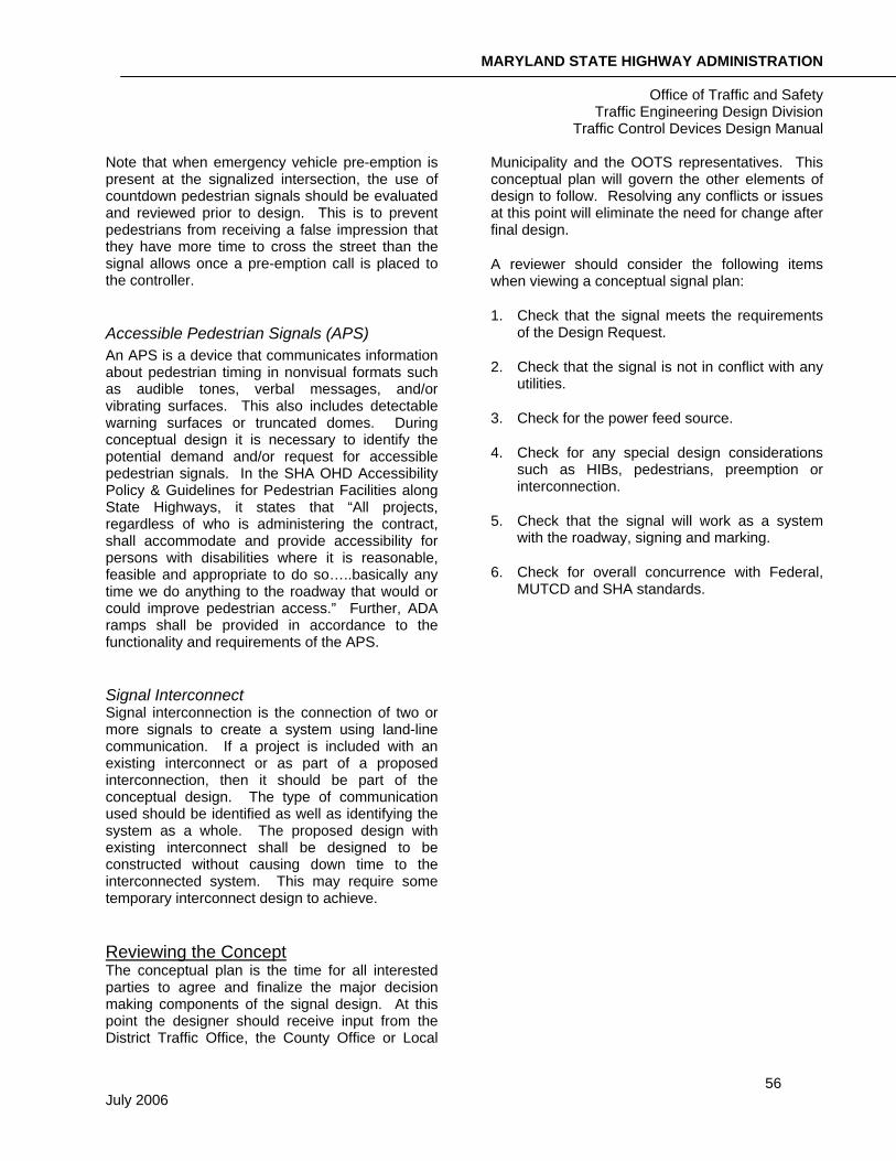
The signal controller is the heart of the signal. It controls, monitors and operates the signal. SHA uses only eight-phase, fully actuated controller units. The controller unit is composed of several elements for optimal performance. SHA uses NEMA TS-2 standards for its controllers and components.
Figure 43 - Signal Controller
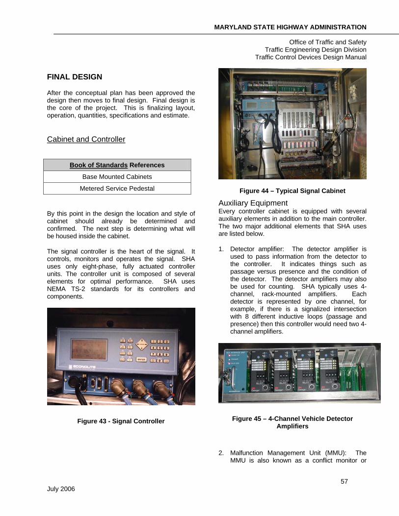
Figure 44 – Typical Signal Cabinet
Auxiliary Equipment Every controller cabinet is equipped with several auxiliary elements in addition to the main controller. The two major additional elements that SHA uses are listed below.
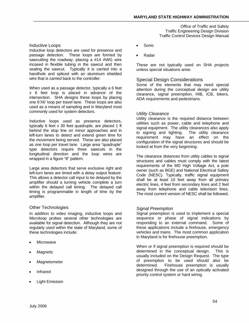
1. Detector amplifier: The detector amplifier is used to pass information from the detector to the controller. It indicates things such as passage versus presence and the condition of the detector. The detector amplifiers may also be used for counting. SHA typically uses 4-channel, rack-mounted amplifiers. Each detector is represented by one channel, for example, if there is a signalized intersection with 8 different inductive loops (passage and presence) then this controller would need two 4-channel amplifiers.
Figure 45 – 4-Channel Vehicle Detector Amplifiers
2. Malfunction Management Unit (MMU): The MMU is also known as a conflict monitor or
MARYLAND STATE HIGHWAY ADMINISTRATION
Office of Traffic and Safety Traffic Engineering Design Division
Traffic Control Devices Design Manual
58 July 2006
intersection monitor. A MMU is designed to detect and respond to improper and/or conflicting signal operation and improper operating voltages. This includes such things as power failures, flashing operation failure, controller timing, detector status, alarms, cycle failure and voltage. SHA includes an MMU with battery back up for most of their projects. Some of these units are now incorporated into the main controller.
Power and Communication Like any other computer or system, the signal controller needs power. A location for a power feed should have been identified during the field work. The requirements for connecting electrical power from the local utility lines to signal equipment may vary among utility companies. Service connections normally consist of a single-phase circuit of 120/240 volts, 60 Hz and 60 ampere (30 ampere for HIB) service connected to the nearest source of power. The service point may be from either an overhead or underground power line. The power source location shall be confirmed with the power company during design, but the final request for service is done during construction. Generally, a metered service pedestal is used between the power source and the cabinet for new power drops.
In addition to power, SHA also uses a telephone line to maintain and operate the signals. This should also be incorporated with the design. The telephone and power sources are identified with conduit running to them, but usually the power and/or phone company installs the actual line.
Special Notes SHA furnishes all of the cabinets and controllers for their signalized intersections except in the case of a developer/other funded project. They are put together and tested by OOTS.
• Montgomery County supplied cabinets are not supplied with an intersection monitor
• Special relay packages are used for two signals that are interconnected as a master/slave operation
Phasing Phasing is assigning the right of way and combination of one or more movements during a cycle. SHA uses the standard National Electrical Manufacturers Association (NEMA) phasing for signal operation.
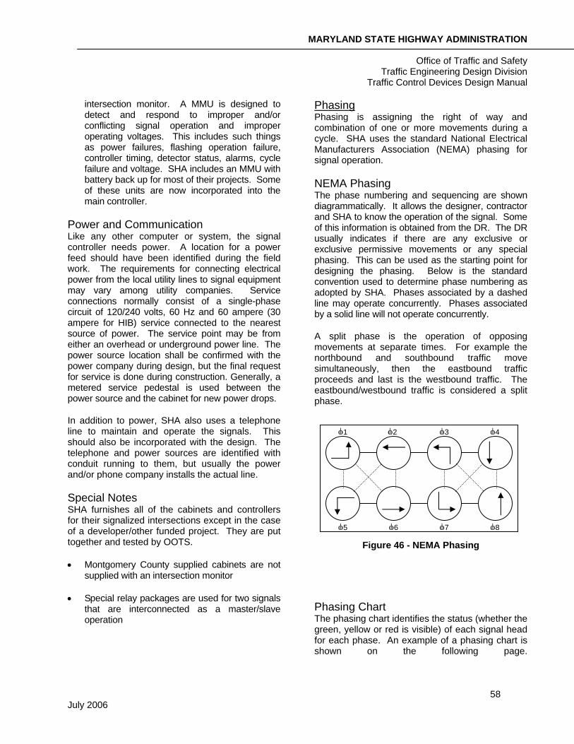
NEMA Phasing The phase numbering and sequencing are shown diagrammatically. It allows the designer, contractor and SHA to know the operation of the signal. Some of this information is obtained from the DR. The DR usually indicates if there are any exclusive or exclusive permissive movements or any special phasing. This can be used as the starting point for designing the phasing. Below is the standard convention used to determine phase numbering as adopted by SHA. Phases associated by a dashed line may operate concurrently. Phases associated by a solid line will not operate concurrently.
A split phase is the operation of opposing movements at separate times. For example the northbound and southbound traffic move simultaneously, then the eastbound traffic proceeds and last is the westbound traffic. The eastbound/westbound traffic is considered a split phase.
Figure 46 - NEMA Phasing
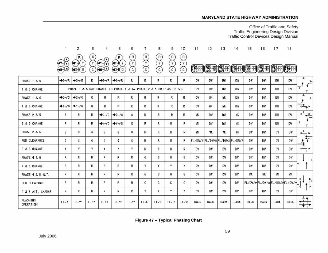
Phasing Chart The phasing chart identifies the status (whether the green, yellow or red is visible) of each signal head for each phase. An example of a phasing chart is shown on the following page.
φ1 φ2 φ3 φ4
φ5 φ6 φ7 φ8
MARYLAND STATE HIGHWAY ADMINISTRATION
Office of Traffic and Safety Traffic Engineering Design Division
Traffic Control Devices Design Manual
59 July 2006
Figure 47 – Typical Phasing Chart
MARYLAND STATE HIGHWAY ADMINISTRATION
Office of Traffic and Safety Traffic Engineering Design Division
Traffic Control Devices Design Manual
60 July 2006
Signal Heads
Book of Standards References
Signal Head Mounting Details
During the conceptual phase of the design the location of the signal heads is determined. By this point the designer is now ready to finalize locations, determine the size of signal heads and the combination of signal sections for each head. All new projects shall require the installation of black-faced, LED signal heads unless otherwise specified.
Size of Signal Heads There are two sizes of signal heads used for intersection control, 8 inches and 12 inches. Twelve-inch indications shall be used when:
• Use 12 inch heads most of the time except in small towns and with nearside combinations.
• The 85th percentile speed along a specific approach to an intersection is greater than 40 mph.
• When signalized intersections are used in conjunction with lane-control signal heads.
• When a driver does not expect a signalized intersection.
• When background lighting may compete with the signal display.
• For ICB and HIB locations
• For all arrow indications.
• See MUTCD for more information.
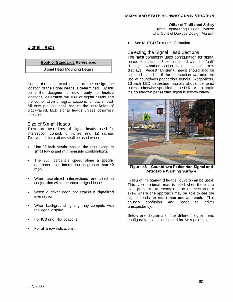
Selecting the Signal Head Sections The most commonly used configuration for signal heads is a simple 3 section head with the “ball” display. Another option is the use of arrow displays. Pedestrian signal heads should also be selected based on if the intersection warrants the use of countdown pedestrian signals. Regardless, 16 inch LED pedestrian signals should be used unless otherwise specified in the D.R. An example if a countdown pedestrian signal is shown below.
Figure 48 – Countdown Pedestrian Signal and Detectable Warning Surface
In lieu of the standard heads, louvers can be used. This type of signal head is used when there is a sight problem. An example is an intersection at a skew where one approach may be able to see the signal heads for more than one approach. This causes confusion and leads to driver unexpectancy.
Below are diagrams of the different signal head configurations and sizes used for SHA projects.
MARYLAND STATE HIGHWAY ADMINISTRATION
Office of Traffic and Safety Traffic Engineering Design Division
Traffic Control Devices Design Manual
61 July 2006
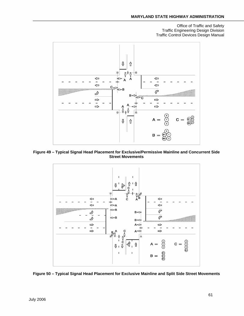
Figure 49 – Typical Signal Head Placement for Exclusive/Permissive Mainline and Concurrent Side Street Movements
Figure 50 – Typical Signal Head Placement for Exclusive Mainline and Split Side Street Movements
MARYLAND STATE HIGHWAY ADMINISTRATION
Office of Traffic and Safety Traffic Engineering Design Division
Traffic Control Devices Design Manual
62 July 2006
Detection
Book of Standards References
Loop Detector Lead In
Loop Detector and Probe Installations
At this point in design, the operation and technology of the detection have been determined.
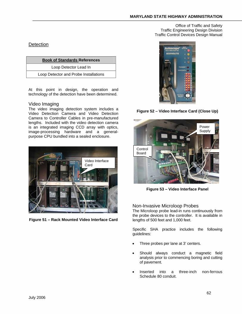
Video Imaging The video imaging detection system includes a Video Detection Camera and Video Detection Camera to Controller Cables in pre-manufactured lengths. Included with the video detection camera is an integrated imaging CCD array with optics, image-processing hardware and a general-purpose CPU bundled into a sealed enclosure.
Figure 51 – Rack Mounted Video Interface Card
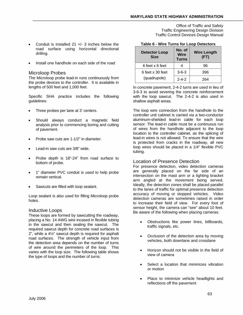
Figure 52 – Video Interface Card (Close Up)
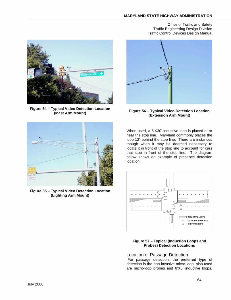
Figure 53 – Video Interface Panel
Non-Invasive Microloop Probes The Microloop probe lead-in runs continuously from the probe devices to the controller. It is available in lengths of 500 feet and 1,000 feet.
Specific SHA practice includes the following guidelines:
• Three probes per lane at 3’ centers.
• Should always conduct a magnetic field analysis prior to commencing boring and cutting of pavement.
• Inserted into a three-inch non-ferrous Schedule 80 conduit.
Video Interface Card
Power Supply
Control Board
MARYLAND STATE HIGHWAY ADMINISTRATION
Office of Traffic and Safety Traffic Engineering Design Division
Traffic Control Devices Design Manual
63 July 2006
• Conduit is installed 21 +/- 3 inches below the road surface using horizontal directional drilling.
• Install one handhole on each side of the road
Microloop Probes The Microloop probe lead-in runs continuously from the probe devices to the controller. It is available in lengths of 500 feet and 1,000 feet.
Specific SHA practice includes the following guidelines:
• Three probes per lane at 3’ centers.
• Should always conduct a magnetic field analysis prior to commencing boring and cutting of pavement.
• Probe saw cuts are 1-1/2” in diameter.
• Lead-in saw cuts are 3/8” wide.
• Probe depth is 18”-24” from road surface to bottom of probe.
• 1” diameter PVC conduit is used to help probe remain vertical.
• Sawcuts are filled with loop sealant.
Loop sealant is also used for filling Microloop probe holes.
Inductive Loops These loops are formed by sawcutting the roadway, placing a No. 14 AWG wire incased in flexible tubing in the sawcut and then sealing the sawcut. The required sawcut depth for concrete road surfaces is 2”, while a 4½” sawcut depth is required for asphalt road surfaces. The strength of vehicle input from the detection area depends on the number of turns of wire around the perimeters of the loop. This varies with the loop size. The following table shows the type of loops and the number of turns:
Table 6 - Wire Turns for Loop Detectors
Detector Loop Size
No. of Wire
Turns Wire Length
(FT)
6 feet x 6 feet 4 96 3-6-3 396 6 feet x 30 feet
(quadrupole) 2-4-2 264
In concrete pavement, 2-4-2 turns are used in lieu of 3-6-3 to avoid severing the concrete reinforcement with the loop sawcut. The 2-4-2 is also used in shallow asphalt areas.
The loop wire connection from the handhole to the controller unit cabinet is carried via a two-conductor aluminum-shielded lead-in cable for each loop sensor. The lead-in cable must be a continuous run of wires from the handhole adjacent to the loop location to the controller cabinet, as the splicing of lead-in wires is not allowed. To ensure that the wire is protected from cracks in the roadway, all new loop wires should be placed in a 1/4” flexible PVC tubing.
Location of Presence Detection For presence detection, video detection cameras are generally placed on the far side of an intersection on the mast arm or a lighting bracket arm angled at the movement being served. Ideally, the detection zones shall be placed parallel to the lanes of traffic for optimal presence detection accuracy of moving or stopped vehicles. Video detection cameras are sometimes raised in order to increase their field of view. For every foot of sensor height, the camera can “see” about 10 feet. Be aware of the following when placing cameras:
• Obstructions like power lines, billboards, traffic signals, etc.
• Occlusion of the detection area by moving vehicles, both downlane and crosslane
• Horizon should not be visible in the field of view of camera
• Select a location that minimizes vibration or motion
• Place to minimize vehicle headlights and reflections off the pavement
MARYLAND STATE HIGHWAY ADMINISTRATION
Office of Traffic and Safety Traffic Engineering Design Division
Traffic Control Devices Design Manual
64 July 2006
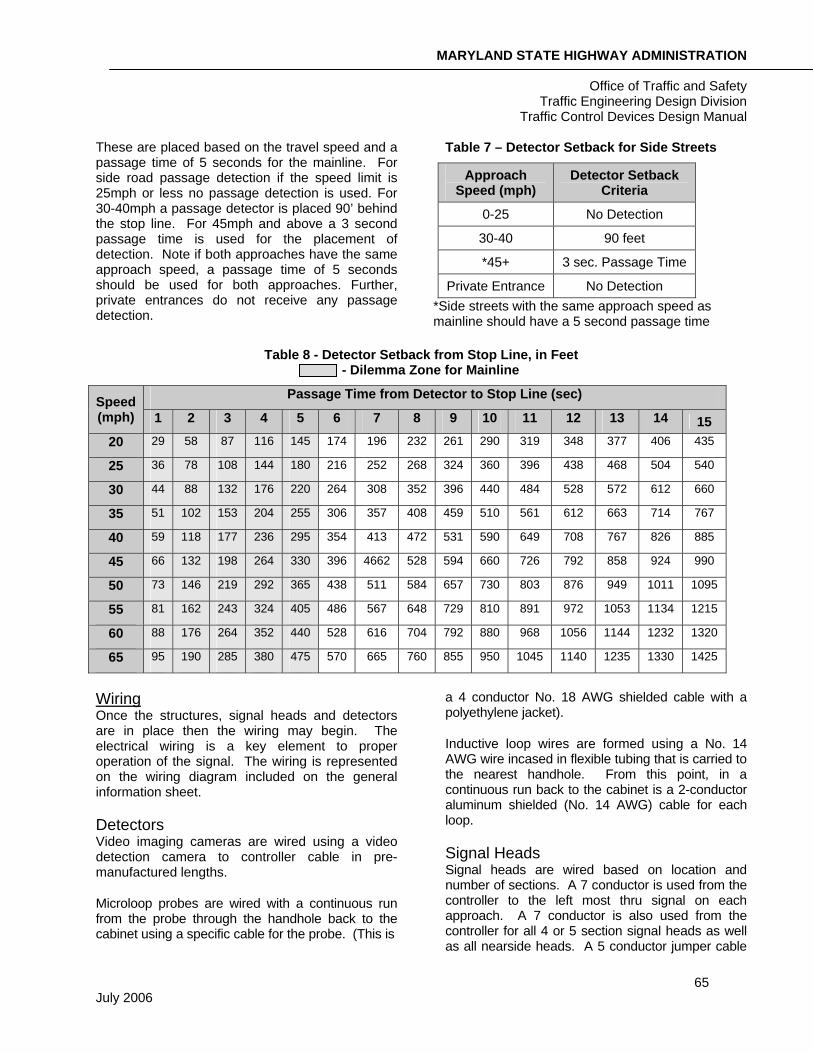
Figure 54 – Typical Video Detection Location
(Mast Arm Mount)
Figure 55 – Typical Video Detection Location
(Lighting Arm Mount)
Figure 56 – Typical Video Detection Location (Extension Arm Mount)
When used, a 6’X30’ inductive loop is placed at or near the stop line. Maryland commonly places the loop 12” behind the stop line. There are instances though when it may be deemed necessary to locate it in front of the stop line to account for cars that stop in front of the stop line. The diagram below shows an example of presence detection location.
Figure 57 – Typical (Induction Loops and Probes) Detection Locations
Location of Passage Detection For passage detection, the preferred type of detection is the non-invasive micro-loop; also used are micro-loop probes and 6’X6’ inductive loops.
MARYLAND STATE HIGHWAY ADMINISTRATION
Office of Traffic and Safety Traffic Engineering Design Division
Traffic Control Devices Design Manual
65 July 2006
These are placed based on the travel speed and a passage time of 5 seconds for the mainline. For side road passage detection if the speed limit is 25mph or less no passage detection is used. For 30-40mph a passage detector is placed 90’ behind the stop line. For 45mph and above a 3 second passage time is used for the placement of detection. Note if both approaches have the same approach speed, a passage time of 5 seconds should be used for both approaches. Further, private entrances do not receive any passage detection.
Table 7 – Detector Setback for Side Streets
Approach Speed (mph)
Detector Setback Criteria
0-25 No Detection
30-40 90 feet
*45+ 3 sec. Passage Time
Private Entrance No Detection *Side streets with the same approach speed as mainline should have a 5 second passage time
Table 8 - Detector Setback from Stop Line, in Feet - Dilemma Zone for Mainline
Passage Time from Detector to Stop Line (sec) Speed (mph) 1 2 3 4 5 6 7 8 9 10 11 12 13 14 15
20 29 58 87 116 145 174 196 232 261 290 319 348 377 406 435
25 36 78 108 144 180 216 252 268 324 360 396 438 468 504 540
30 44 88 132 176 220 264 308 352 396 440 484 528 572 612 660
35 51 102 153 204 255 306 357 408 459 510 561 612 663 714 767
40 59 118 177 236 295 354 413 472 531 590 649 708 767 826 885
45 66 132 198 264 330 396 4662 528 594 660 726 792 858 924 990
50 73 146 219 292 365 438 511 584 657 730 803 876 949 1011 1095
55 81 162 243 324 405 486 567 648 729 810 891 972 1053 1134 1215
60 88 176 264 352 440 528 616 704 792 880 968 1056 1144 1232 1320
65 95 190 285 380 475 570 665 760 855 950 1045 1140 1235 1330 1425
Wiring Once the structures, signal heads and detectors are in place then the wiring may begin. The electrical wiring is a key element to proper operation of the signal. The wiring is represented on the wiring diagram included on the general information sheet.
Detectors Video imaging cameras are wired using a video detection camera to controller cable in pre-manufactured lengths.
Microloop probes are wired with a continuous run from the probe through the handhole back to the cabinet using a specific cable for the probe. (This is
a 4 conductor No. 18 AWG shielded cable with a polyethylene jacket).
Inductive loop wires are formed using a No. 14 AWG wire incased in flexible tubing that is carried to the nearest handhole. From this point, in a continuous run back to the cabinet is a 2-conductor aluminum shielded (No. 14 AWG) cable for each loop.
Signal Heads Signal heads are wired based on location and number of sections. A 7 conductor is used from the controller to the left most thru signal on each approach. A 7 conductor is also used from the controller for all 4 or 5 section signal heads as well as all nearside heads. A 5 conductor jumper cable
MARYLAND STATE HIGHWAY ADMINISTRATION
Office of Traffic and Safety Traffic Engineering Design Division
Traffic Control Devices Design Manual
66 July 2006
is used from the left most head to the adjacent signal head in the same phase. A 5 conductor cable is used for exclusive left-turn phases.
In special cases with 4 or more signal heads, additional cables may be required from the controller to signal heads to allow the signal heads to be monitored separately.
Lighting When intersection lighting is used in conjunction with a signal it requires a 2-conductor No. 12 AWG tray cable.
Signal Preemption An optically activated priority control system requires the wiring of the optical detector back to the signal cabinet. This application also has a special cable that is a 4-conductor No. 20 AWG (7x8) stranded cable.
When using a hard wire and push button for signal preemption, a 3-conductor No. 14 AWG cable is used from the firehouse to the cabinet.
Pedestrian Signals and Pushbuttons Pedestrian signal heads (Walk/Don’t Walk and/or Countdown) are each wired using a 5-conductor No.14 AWG cable. This allows for the installation of APSs now or in the future. The pedestrian pushbutton uses a 2-conductor No. 14 AWG cable. These are all run back to the cabinet.
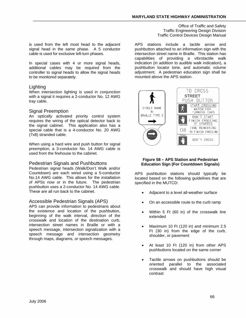
Accessible Pedestrian Signals (APS) APS can provide information to pedestrians about the existence and location of the pushbutton, beginning of the walk interval, direction of the crosswalk and location of the destination curb, intersection street names in Braille or with a speech message, intersection signalization with a speech message and intersection geometry through maps, diagrams, or speech messages.
APS stations include a tactile arrow and pushbutton attached to an information sign with the intersection street name in Braille. This station has capabilities of providing a vibrotactile walk indication (in addition to audible walk indication), a pushbutton locator tone, and automatic volume adjustment. A pedestrian education sign shall be mounted above the APS station.
Figure 58 – APS Station and Pedestrian Education Sign (For Countdown Signals)
APS pushbutton stations should typically be located based on the following guidelines that are specified in the MUTCD:
• Adjacent to a level all-weather surface
• On an accessible route to the curb ramp
• Within 5 Ft (60 in) of the crosswalk line extended
• Maximum 10 Ft (120 in) and minimum 2.5 Ft (30 in) from the edge of the curb, shoulder, or pavement
• At least 10 Ft (120 in) from other APS pushbuttons located on the same corner
• Tactile arrows on pushbuttons should be oriented parallel to the associated crosswalk and should have high visual contrast
STREET
MARYLAND STATE HIGHWAY ADMINISTRATION
Office of Traffic and Safety Traffic Engineering Design Division
Traffic Control Devices Design Manual
67 July 2006
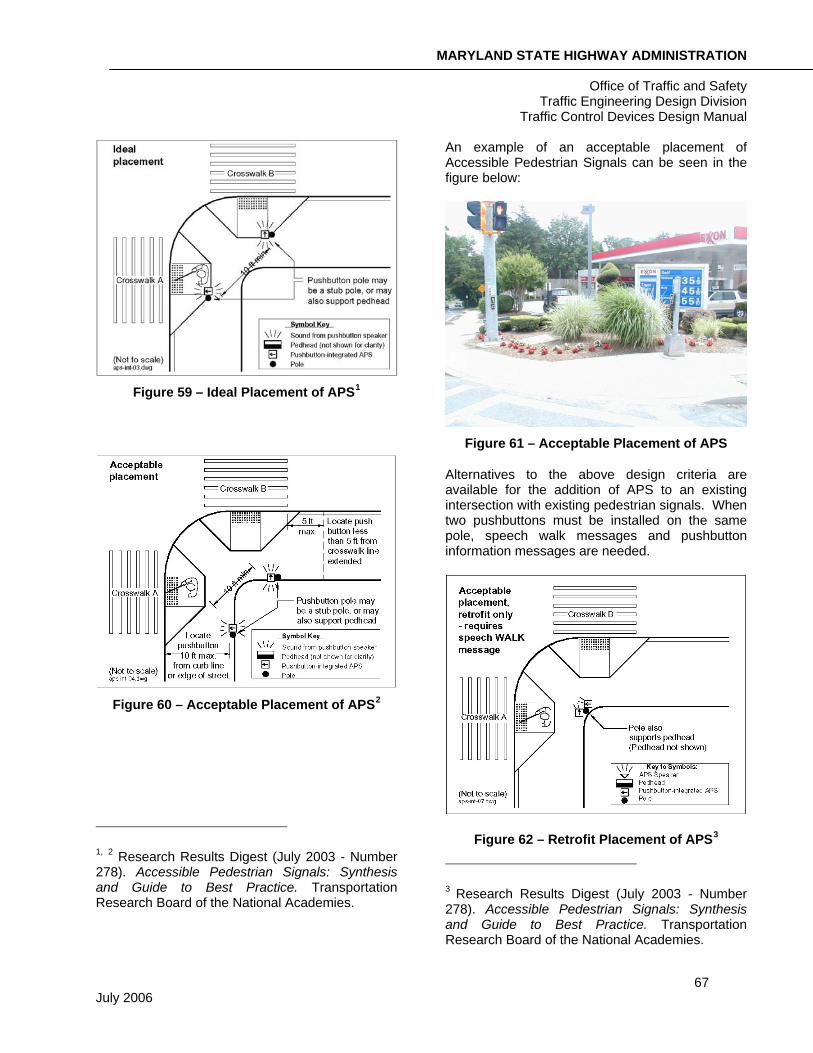
Figure 59 – Ideal Placement of APS1
Figure 60 – Acceptable Placement of APS2
1, 2 Research Results Digest (July 2003 - Number 278). Accessible Pedestrian Signals: Synthesis and Guide to Best Practice. Transportation Research Board of the National Academies.
An example of an acceptable placement of Accessible Pedestrian Signals can be seen in the figure below:
Figure 61 – Acceptable Placement of APS
Alternatives to the above design criteria are available for the addition of APS to an existing intersection with existing pedestrian signals. When two pushbuttons must be installed on the same pole, speech walk messages and pushbutton information messages are needed.
Figure 62 – Retrofit Placement of APS3
3 Research Results Digest (July 2003 - Number 278). Accessible Pedestrian Signals: Synthesis and Guide to Best Practice. Transportation Research Board of the National Academies.
MARYLAND STATE HIGHWAY ADMINISTRATION
Office of Traffic and Safety Traffic Engineering Design Division
Traffic Control Devices Design Manual
68 July 2006
Grounding Grounding is the acting of connecting an electrical circuit to the earth. It prevents the buildup of voltages. This is a key safety step in any design with electrical equipment. In order for mast arm signals and/or pedestal pole foundation(s) to be grounded, a continuous “homerun” ground wire is attached to the steel structure, run to the closest handhole where it is attached to a ground rod and then run back to the cabinet source ground. For span wire designs, ground wire is necessary for each strain pole to a ground rod placed in a nearby handhole. Continuous ground wire is run from the cabinet to the nearest strain pole. For all signals the handhole nearest the cabinet requires one ground rod.
Conduits
Book of Standards References
Signal Structure Foundations
Lighting Structure and Control Cabinet Foundation
Conduit Details
Base Mounted Cabinet Layout
Conduit acts as duct for electrical cables. Conduits come in various materials and sizes. The most common materials are polyvinyl chloride (PVC) and galvanized steel. For most applications with signals, rigid PVC, schedule 80 is used.
Installation There are three methods of installing conduits:
1. Trench: Trenching is the most common and least expensive method. Its application is for along side a roadway to place the conduit in a grassed or dirt area.
2. Slot: Slotting is used to place the conduit in the roadway. The roadway or driveway pavement is cut wide enough to lay the conduit and then the roadway is patched. This method is more expensive than trenching, but typically less expensive than boring.
3. Bore: Boring is a method of placing the conduit under the roadway, driveway or other major feature without disturbance. It is typically the most expensive method and requires major equipment.
Boring is preferred over slotting because interruption to traffic is minimized, damage to the roadway surface/structure is minimal, but the cost is slightly higher. When boring conduits, there must be sufficient room and right-of-way (approximately 10 feet in the direction of the conduit) to place machinery to perform the boring operation. Slotting in pavement is generally acceptable to avoid conflicts with underground utilities.
Bends Bends are used in the signal pole bases and in the base of the controller cabinet. A 3-inch minimum bend is installed in all pole bases with exception to the pole base next to the controller cabinet for an intersection with strain poles; one 2-inch and two 3-inch bends should be installed in this pole base. Pedestal poles require a 2-inch minimum bend and the controller cabinet requires two (2) 4-inch and two (2) 2-inch bends. Additional conduit bends shall be added appropriately if conduit fill exceeds recommended capacity. Further, a 2-inch bend should be installed if proposed overhead service is run to the signal pole.
Sizes The Administration uses four electrical conduit sizes: 1”, 2”, 3” and 4”. The one-inch conduit used is either a liquid-tight flexible non-metallic electrical conduit or a rigid galvanized conduit. The two, three and four-inch conduits used are all schedule 80 rigid PVC conduits. Determining conduit size is based on the conduit fill capacity and the general use of the conduit.
Conduit Fill Capacity The determination of the conduit size should first be based on the capacity of the conduit. The capacity is based on the cross-sectional area of the conduit and the desired percentage of fill. As a general rule of thumb in Maryland, when designing a new signal it is better to design conservatively to allow for future modifications. Using 25% of the cross-sectional area of the conduit is the desirable
MARYLAND STATE HIGHWAY ADMINISTRATION
Office of Traffic and Safety Traffic Engineering Design Division
Traffic Control Devices Design Manual
69 July 2006
maximum for new signals, and 40% is the maximum for rebuilds/modifications. Remember that different conduits have different capacities. For example, the 40% capacity of a 2” schedule 80 rigid PVC conduit is 1.150 sq in. The most current version of the National Electrical Code should always be followed for determining the fill capacity.
Cross-sectional areas of cables are also found in the current version of the National Electrical Code.
General Uses After determining the required capacity of the conduit, some of these general guidelines may be used for deciding on conduit size. Always check the conduit capacity and use it as the final design decision.
• One-inch conduit is used as a detector wire sleeve for the loop wires between the edge of pavement and the nearest handhole. A one-inch liquid-tight flexible non-metallic electrical conduit is used for lengths shorter than 6 feet. For longer lengths, a one-inch rigid galvanized
conduit should be used.
• A minimum two-inch conduit is used between handholes to transport detector lead-in wires and signal cables. A two-inch conduit is also used from the cabinet to the telephone feed.
• Three-inch conduit is used between the signal pole and handhole. For the pole that is closest to the controller cabinet the Administration requires two three-inch conduits in this case for intersections with strain poles and span wire. Three-inch conduits are also used for interconnection, under driveways and non-invasive microloop probes.
• Four-inch conduits are installed between the controller cabinet and the closest handhole. The Administration requires two four-inch conduits in this case. A four inch conduit is also used from the control cabinet to the power feed and all underground road crossings.
Handholes
Book of Standards References
Handhole Installation
Handholes, also known as junction boxes, are small concrete boxes placed underground with a steel lid. They are used as a point for cable to enter where it may be spliced or change direction. The only splice points are when loop wire is spliced to the home run cable. The use of handholes with signal design is critical. Handholes should be placed near each signal pole, at the cabinet, where a change in direction is necessary for the cable and at a point where the detector wire can easily be brought in. On long conduit runs the maximum distance between handholes is 200 feet.
Signs
A signal plan may include some signing when designed independent of a signing and marking plan. Traffic signs installed in conjunction with new or reconstructed signals generally include street name signs, temporary signal ahead warning signs (on mainline only), signal related regulatory signs such as “left-turn yield on green”, lane use control signs and pedestrian push-button signs. The placement of the sign should take into consideration the size of the sign, position over travel lanes and offset from the nearest signal head to the edge of the sign plate. See the Sign Design Section.
Pavement Markings A signal plan may also include some pavement marking design when designed independent of a signing and marking plans. The types of pavement markings to be installed will be indicated in the Design Request. They may include crosswalks, stop lines, message/arrow markings, lane lines, channelizing lines, edge lines and the removal of existing markings. The Designer is responsible for detailing new pavement markings to a point where they can be transitioned into the existing markings. See the Sign Design Section for further information on pavement markings.
Book of Standards References
Pedestrian Push Button Assembly and Sign
MARYLAND STATE HIGHWAY ADMINISTRATION
Office of Traffic and Safety Traffic Engineering Design Division
Traffic Control Devices Design Manual
70 July 2006
Lighting Lighting as part of a signal design is termed intersection lighting. This is lighting typically attached to the signal poles via a bracket arm. See the diagram below for placement of the luminaires at an intersection. The lighting is wired separately and run to the cabinet, but is usually maintained by an independent meter and disconnect. For more information about lighting refer to the Lighting Design Section.
MARYLAND STATE HIGHWAY ADMINISTRATION
Office of Traffic and Safety Traffic Engineering Design Division
Traffic Control Devices Design Manual
71 July 2006
SIGNAL SYSTEMIZATION
A signal system is interconnecting two or more signals along a roadway or network of roadways. There are two basic types of signal systems, open-loop system and closed-loop system.
An open-loop system operates the intersection controller, but does not receive feedback status. It may operate with a master controller that supervises the cycle length, offsets and splits for each signal or it may operate without a master controller as a coordinated system of intersections.
A closed-loop system provides two-way communication between the intersection controller and the master controller. Most systems then have a control center that communicates with the master controller. With a closed-loop system, the master controller operates the intersection controller as well as receiving and responding to diagnostic information such as speed, density, volume and capacity.
A signal system has three major components in the design process.
1. Controller
2. Communication Links
3. System Detection
Cabinet and Controller The controller of a signal system is made of two parts. First is the individual intersection controller, which is designed as part of the intersection signal. Second is the master controller, which is designed as part of the system. The master controller supervises the individual intersection controllers. With the master controller that SHA uses, it may control up to 24 individual intersection controllers.
The master controller is housed in a cabinet like an intersection controller. The master shall be housed in a base mount cabinet, typically a NEMA size 6.
Placement of the cabinet is often defined in the DR. The location of the cabinet is determined
based on location of power source, safe access and availability of right-of-way.
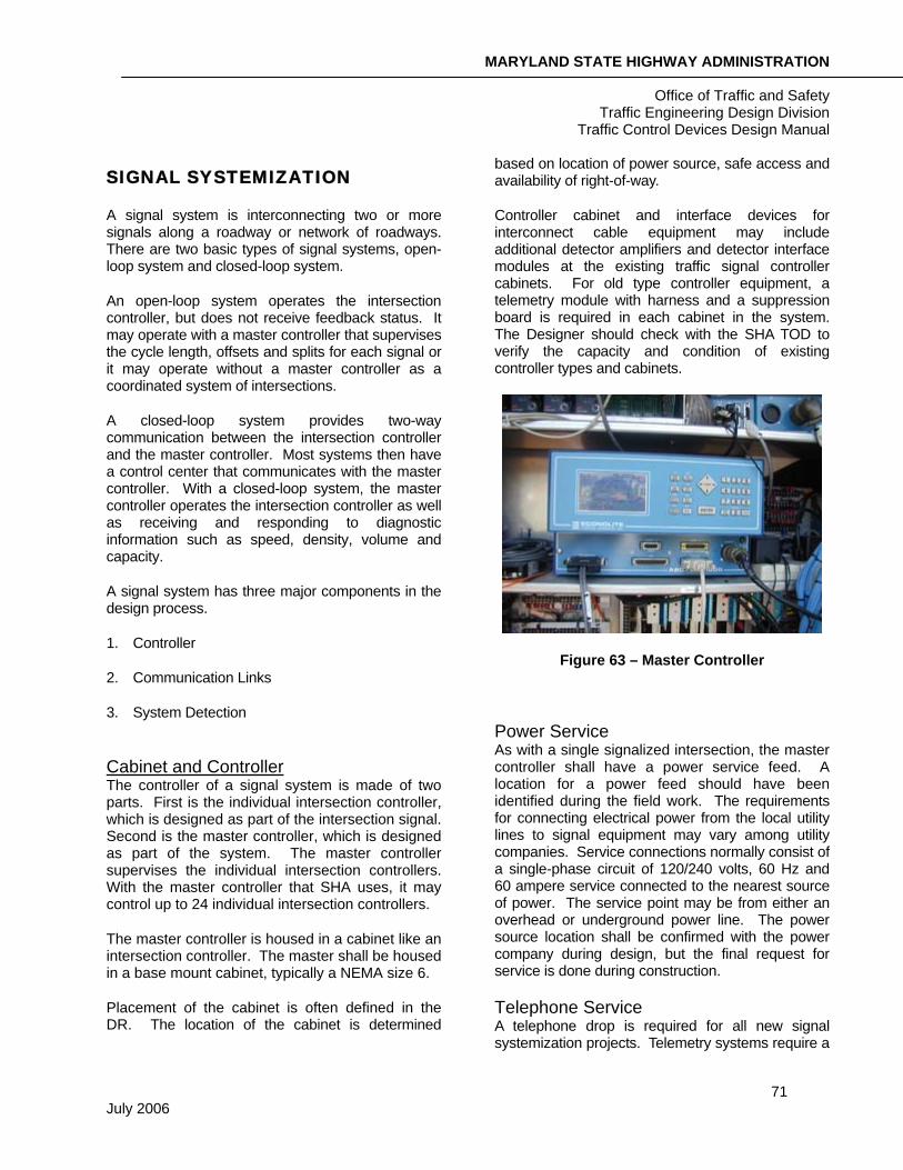
Controller cabinet and interface devices for interconnect cable equipment may include additional detector amplifiers and detector interface modules at the existing traffic signal controller cabinets. For old type controller equipment, a telemetry module with harness and a suppression board is required in each cabinet in the system. The Designer should check with the SHA TOD to verify the capacity and condition of existing controller types and cabinets.
Figure 63 – Master Controller
Power Service As with a single signalized intersection, the master controller shall have a power service feed. A location for a power feed should have been identified during the field work. The requirements for connecting electrical power from the local utility lines to signal equipment may vary among utility companies. Service connections normally consist of a single-phase circuit of 120/240 volts, 60 Hz and 60 ampere service connected to the nearest source of power. The service point may be from either an overhead or underground power line. The power source location shall be confirmed with the power company during design, but the final request for service is done during construction.
Telephone Service A telephone drop is required for all new signal systemization projects. Telemetry systems require a

MARYLAND STATE HIGHWAY ADMINISTRATION
Office of Traffic and Safety Traffic Engineering Design Division
Traffic Control Devices Design Manual
72 July 2006
telephone service directly to the master cabinet. Any existing telephone service at proposed signals, which will be systemized, should be removed. TOD is responsible for the coordination of the new telephone drop with the local telephone company. Once a location has been determined, TEDD will provide, via signal plans, a 2 inch conduit from the cabinet to the nearest utility pole. TOD prepares a letter to the telephone company requesting a new telephone service. TOD should determine the address of the intersection and the address and a telephone number of the closest business or residence to the intersection. A preliminary set of interconnect design plans should be included with the Request Letter to the telephone company.
Normally, SHA installs telephone service in all isolated controllers. Therefore, for projects involving systemization of existing traffic signals, the Designer should verify if existing telephone service at the controller nearest to the on-street master may be extended to the on-street master controller cabinet.
Communication Links In order to implement a signal system, the local intersection controllers and master controller must be interconnected via communication links. Communications links may be designed using several different techniques. Some of these may include:
• Cable
• Wireless
• Leased Local Telephone Services
• Leased CATV Cable Channels
• Switched Telecommunication Service
Wiring Maryland uses cable for its communication links. Three common types of cable are twisted pair, coaxial and fiber optic. Cable may be run overhead or underground.
Interconnect cables are generally 12-pair jelly-filled, No. 19 A.W.G., for underground installations and/or 12-pair self-supporting, No. 19 A.W.G., for overhead installations. The decision to install interconnect
cables underground versus overhead should be based on cost and constructability. If both underground and overhead installation is necessary, a 12-pair self-supporting cable is used throughout the entire run.
Figure 64 – Fiber Optic Cables
Figure 65 – 12-Pair Interconnect Cables
Underground When the design incorporates underground communication links, PVC conduit is used as with signalized intersections.
Fiber Patch Panel
Fiber Optic Cable
Termination Block
I/C Wires
MARYLAND STATE HIGHWAY ADMINISTRATION
Office of Traffic and Safety Traffic Engineering Design Division
Traffic Control Devices Design Manual
73 July 2006
Handholes are also installed at a maximum spacing of 200 feet to accommodate the pulling of under-ground interconnect cables.
Overhead An overhead utility company attachment agreement is required if interconnect cables are to be placed on telephone, electric company or joint use poles.
Overhead attachment details should be shown on the plan to indicate how the interconnect cables should be installed, e.g., face of pole, height, support and clearance from other utilities and overhead clearances over driveway entrances. This element of the design can be the most critical aspect of the project. The Designer is responsible for the coordination of the overhead attachment agreement and any adjustments required with the owners of the overhead utilities.
Detection
Book of Standards References
Detection
Loop Detector Installation
A signal system needs detection to feed information back to the controller. The term “system loops” or “sampling detectors” is often used in reference to this. The operation of system detection is usually passage and presence. It collects data such as occupancy, queues, volumes and speeds and sends it back to the controller. The technologies used are the same as those discussed in the intersection signal design, but most commonly a simple 6’X6’ inductive loop is used for the system detection. System detection runs directly back to the master controller.
The placement of the system detection is designed differently than the placement of the individual intersection detection. The specific location of system detectors depends on the traffic patterns, direction of traffic, distribution of traffic and location of heavily traveled intersections within the arterial system. The goal is to locate the detectors to collect data that is representative of the major traffic flow in the system. In most cases, system detectors are
placed on the upstream and downstream ends of the arterial. One system detector per lane shall be installed.
MARYLAND STATE HIGHWAY ADMINISTRATION
Office of Traffic and Safety Traffic Engineering Design Division
Traffic Control Devices Design Manual
74 July 2006
PREPARATION OF AS-BUILTS
As-Built traffic signal plans document the operational and physical conditions of newly constructed traffic signals. As-Built plans are required for all construction activities that change the functional operation of the intersection.
The physical and operational elements of an As-Built plan should include accurate field verification of the following:
• Location of traffic signal equipment (poles, handholes, cabinet and conduits).
• Location of detectors and lead-in cables.
• Location and type of pavement markings.
• Location of signal heads on mast arms or span wires.
• Location of intersection signing and lighting.
• Clearances to overhead utilities.
With As-Built plans, the Designer may translate the Construction Details symbols from the original signal plan sheet into a labeled text on the As-Built plan. For example, the symbol (E) can be translated on the As-Built plan to “Install Handhole”.
An As-Built plan consists of a single plan sheet and contains the following information:
• NEMA phasing chart.
• Existing signs and signals.
• Wiring diagram and a wiring key (placed on the right-hand side above the title block).
• Legend of geometrics and utilities.