signal constellation design tool - cs.virginia.edurobins/papers/signal_constellation... · signal...
TRANSCRIPT
Signal Constellation Design Tool:A Case study in User Interface Synthesis
Gabriel Robins
Computer Science DepartmentUniversity of California, Los Angeles
Los Angeles, CA 90024, [email protected]
Abstract
Signal constellation design is a major subtask of constructing an efficient communicationsystem; it essentially entails trading-off error frequency against information throughput, a chiefoccupation of modem designers. We propose and implement an interactive tool for designing andsimulating arbitrary signal constellations. 'To construct the user interface we have utilized InterfaceBuilder, a new interactive tool that greatly facilitates the synthesis of arbitrary user interfacesthrough an object-oriented methodology. Using the Interface Builder package and the SignalConstellation Design Tool as the target prototype, we show how an order-of-magnitude improvementcan be achieved in the effort required to produce a complex user interface. Our secondary goal is totry to dispel some of the mystique surrounding user interface synthesis on state-of-the-artworkstations by describing in detail the construction of an interactive tool for computer-assistedlearning.
Keywords: User interfaces, User interface tools, Human computer instruction, Man-machineinteraction, Computer-assisted learning, Simulation tools, Object-oriented systems.
1. Introduction
Signal constellation design is a major part of constructing an efficient communication system.This task essentially entails trading off error frequency against information throughput, a chiefoccupation of modem designers. We propose and implement an interactive tool for designing andsimulating arbitrary signal constellations. While the actual code that simulates signal constellationsis rather trivial in itself, the user interface to this code is quite complex. To design and constructthis user interface we have used Interface Builder, a new interactive tool that greatly facilitates thesynthesis of user interfaces through an object-oriented methodology. Using the Interface Builderpackage and the Signal Constellation Design Tool as the target prototype, we show how an order-of-magnitude improvement can be achieved in the effort required to produce a complex user interface,and then draw some conclusions regarding the synthesis of user interfaces in general.
Our secondary goal is to try to dispel some of the mystique surrounding user interface synthesison state-of-the-art workstations. Many otherwise informed researchers have very little experiencein user-interface design, and consequently view user interface design as some sort of a black art, bestleft to specialized hackers to dabble in. By user interface design I mean a collection of functionality(running on a bit-mapped display workstation with a mouse) that interacts with the user in afriendly manner via menus, scroll bars, control buttons, icons, mouse clicks, and key strokes.
We intend to show that, quite to the contrary of these myths, given the proper tools andmethodology, the synthesis of complex user interfaces could be rather trivial. As a case in point, theuser interface described in this document was implemented on a Macintosh, requiring only severaldays of coding, including the time to read the manuals and learn how to use the software. As a by-product of our inquiry, we have synthesized an interactive tool for computer-assisted learning.
1
The first half of this document explains signal constellation design in general and how InterfaceBuilder was used to synthesis the user interface; numerous examples and illustrations are given. Therest of this document describes and illustrates the functionality and usage of the resulting signalconstellation design tool. The annotated Common LISP source code is available upon request both inhardcopy and on a Macintosh diskette.
2. Signal Constellation Design
In designing an efficient communication scheme for band-limited channels, invariably of chiefconcern are the effects of noise and other kind of interference on the system [Forney, Gallager, Lang,Longstaff, and Qureshi]. To combat such interference, and while still aiming to achieve highthroughput, one must carefully design an appropriate signal constellation [Carlyle] [Schwartz][Sklar].
The task of signal constellation design essentially entails trading off error frequency againstinformation throughput and is a chief occupation of modem designers. We propose and implement aninteractive tool to alleviate the task of designing and simulating arbitrary signal constellations. Wewould like our tool to graphically display the signal constellation in two dimensions, allowing the userto visually observe the progressing simulation under interactive modifications to the interferenceparameters of the system.
2.1. The Desired Functionality
In this section we describe in more detail the functionality that we would like our SignalConstellation Design Tool to exhibit. Later we explain how this functionality was actually achieved inthe implementation.
First, we would like to allow the user to select any of a number of "canned" standard signalconstellations. For example, the user may elect to simulate an N-in-a-circle signal constellation andobserve its performance under various levels of noise and distortion. Such selections should be donevia mouse and menu interaction. Next the user may wish to select a certain probability distributionthat would control the generation of random signal points. For example, the user may wish to select aGaussian distribution with a specified variance.
Once the user has selected a particular constellation to simulate/observe, as well as aprobability distribution, that constellation should be drawn on the screen and the simulation mayproceed. During the simulation, the user may interactively modify a number of system parameters,such as the phase jitter and the additive white Gaussian noise level. This would be accomplished bydragging "scroll-bars" identified with the corresponding parameters, or by directly typing in thedesired values.
Using a random number generator, random signals are generated, according to the probabilitydistribution function specified earlier, and are plotted on the signal constellation diagram. After afew minutes, a cumulative scatter-plot of the received signals will become apparent, giving the useran indication of how that signal constellation is performing under the distortion parameter values setpreviously. A cumulative running total of the number of errors encountered so far should bedisplayed, as is the empirically derived error-probability (the number of errors divided by thenumber of signals transmitted.)
The various commands should be also be accessible via clicking appropriate buttons, andalternatively also via menus and keystrokes. In addition, we wish to provide the user with some on-line help and information.
2
2.2. The Main Panel
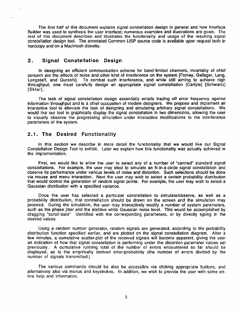
To make the appearance of the user interface more concrete, we give an illustration of how themain panel might appear:
F, El Sina Coselto Deig Too - by 6 e Roin
S
S
SS
US
S
S
Noise Leuel (AWGN)
u •Phase Jitter
SClearD
Simulate)j Suspendi
• IChange Constellation
• IChange Distribution
Signals Sent: 0
Misses: 0
% error: 0
To the left we see the main drawing area where the signal constellation appears; in this case thesignal constellation itself consists of 20 points uniformly distributed on 4 concentric circles. At thetop right we note the interference parameters, as well as the scroll bars and click boxes used tomodify them. Below that we observe several "buttons" each of which will invoke a command if theuser clicks it with the mouse. To the lower right we have the running statistics and error-ratio asthe simulation progresses.
The user may invoke several operations simply by clicking the corresponding buttons. Inaddition, all of these commands are also available from the pull-down menus, as well as throughkeystrokes (i.e. single character keyboard inputs). We may also have at the top a pull-down menubar, representing the various commands the user may invoke; the menu bar is not visible in thisdiagram.
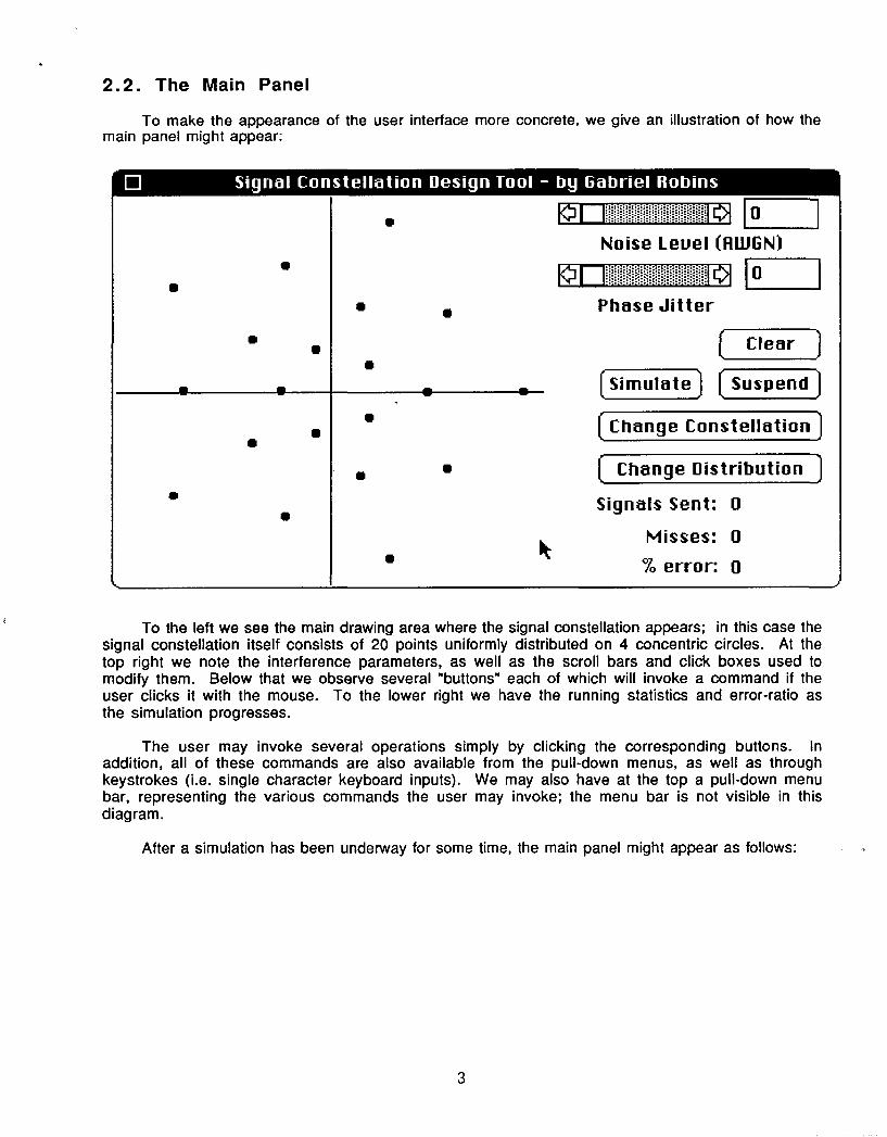
After a simulation has been underway for some time, the main panel might appear as follows:
3
I
[ Sina Coselto Deig Too - by GabrielRobins
The clouds around the signal points represent where the randomly generated signals fell around theactual signal constellation points. In this simulation, given the specified noise parameters, we areobserving an error rate over over one percent, an undesirable situation.
2.3. The Constellation Editor
The panel that allows the user to select and edit a signal constellation is called the ConstellationEditor and may appear as follows:
4
_ _1[li]i~i~i l
Noise Level (fAWGN)
L l! *ii IzHHO-2 I ".. *. 1 1. 1 !!!Phase Jitter
Clear
Simulate Suspend]
Change Constellation)
( Change Distributionj
Signals Sent: 6310
Misses: 70
% error: 1.109350
==E-D Constellation Editor
0 N on a circle
0 N by M rectangle( N on M circles
0 User Specified
R Activate Grid
0 rectangular® Polar
OK
N: I'M:I I
Jot Size:
Circles:
ays: ,Help---
(Redraw ) "
Cancel R [Recompute) Delete 1[ Add
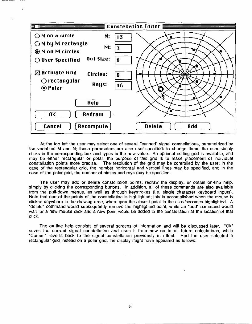
At the top left the user may select one of several "canned" signal constellations, parametrized bythe variables M and N; these parameters are also user-specified: to change them, the user simplyclicks in the corresponding box and types in the new value. An optional editing grid is available, andmay be either rectangular or polar; the purpose of this grid is to make placement of individualconstellation points more precise. The resolution of the grid may be controlled by the user; in thecase of the rectangular grid, the number horizontal and vertical lines may be specified, and in thecase of the polar grid, the number of circles and rays may be specified.
The user may add or delete constellation points, redraw the display, or obtain on-line help,simply by clicking the corresponding buttons. In addition, all of these commands are also availablefrom the pull-down menus, as well as through keystrokes (i.e. single character keyboard inputs).Note that one of the points of the constellation is highlighted; this is accomplished when the mouse isclicked anywhere in the drawing area, whereupon the closest point to the click becomes highlighted. A"delete" command would subsequently remove the highlighted point, while an "add" command wouldwait for a new mouse click and a new point would be added to the constellation at the location of thatclick.
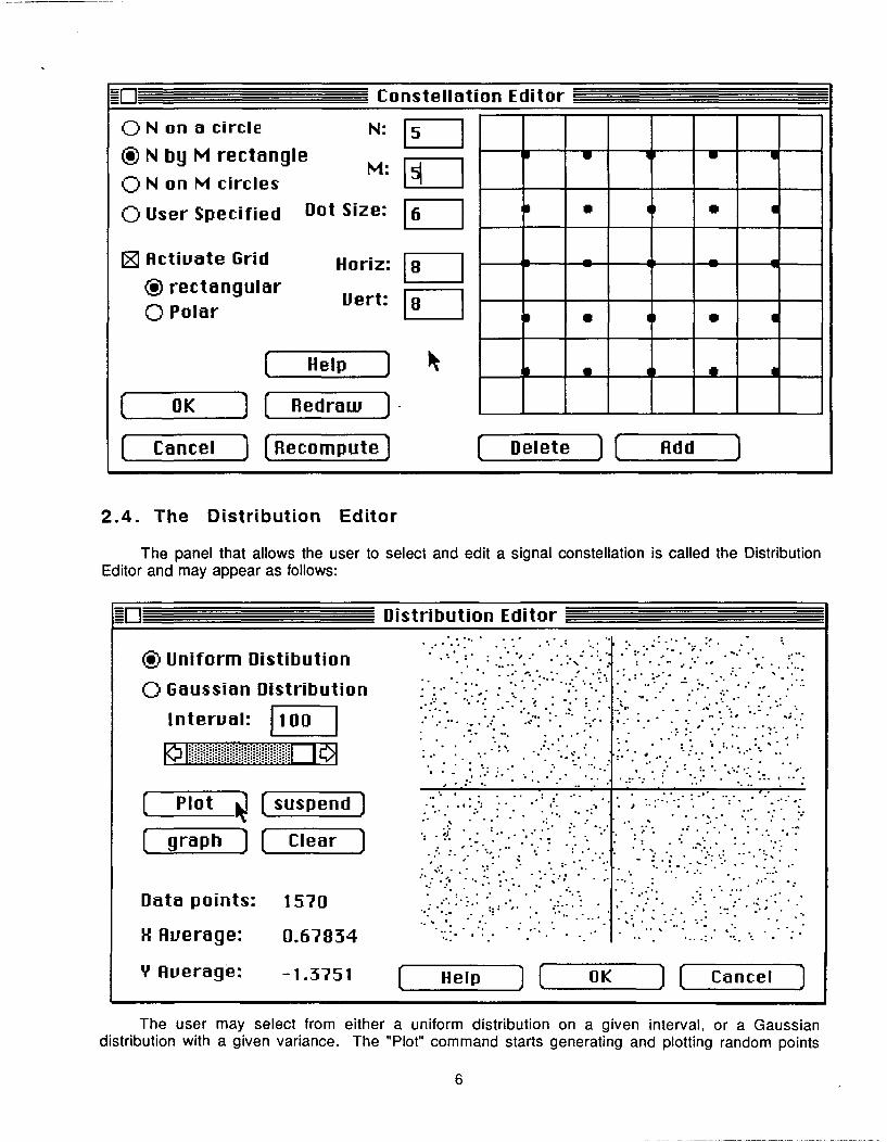
The on-line help consists of several screens of information and will be discussed later. "Ok"saves the current signal constellation and uses it from now on in all future calculations, while"Cancel" reverts back to the signal constellation previously in effect. Had the user selected arectangular grid instead on a polar grid, the display might have appeared as follows:
5
-E-D Constellation Editor
0 N on a circle
(§ N by M rectangle0 N on M circles
O User Specified I
[ Activate Grid
* rectangular0 Polar
OK Re
Cancel =Reci
Dot Si;
Horiz:
Uert:
Helpu]
draw
ompute 1
2.4. The Distribution Editor
The panel that allows the user to select and edit a signal constellation is called the DistributionEditor and may appear as follows:
Uniform Distibution
Gaussian Distribution
Interval: E100
Suspend
-Clear _
1570
0.67834
-1.3751
IPlotigraph
Data points:
H Average:
Y Average: He I p OK Cancel
The user may select from either a uniform distribution on a given interval, or a Gaussiandistribution with a given variance. The "Plot" command starts generating and plotting random points
6
EI"I
"N:
Me':
Delete ] L Add
I0 Distribution Editor
0
ED
• :. • ., :;= " ,:. . -Z
* 0
Distribution Editor
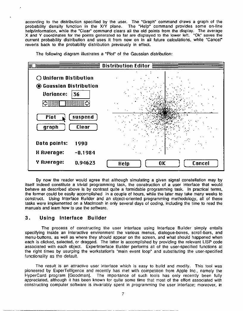
according to the distribution specified by the user. The "Graph" command draws a graph of theprobability density function in the X/Y plane. The "Help" command provides some on-linehelp/information, while the "Clear" command clears all the old points from the display. The averageX and Y coordinates for the points generated so far are displayed to the lower left. "Ok" saves thecurrent probability distribution and uses it from now on in all future calculations, while "Cancel"reverts back to the probability distribution previously in effect.
The following diagram illustrates a "Plot" of the Gaussian distribution:
-0I- Distribution Editor
0 Uniform Distibution
® Gaussian Distribution
Variance:
Z Plot suspend
graph F Clear _
Data points:
H Average:
Y Average:
1990
-0.1984
0.94623
4.. •-
-;A
WH..
Help OK J ( Cancel
By now the reader would agree that although simulating a given signal constellation may byitself indeed constitute a trivial programming task, the construction of a user interface that wouldbehave as described above is by contrast quite a formidable programming task. In practical terms,the former could be easily accomplished in a couple of hours, while the later may take many weeks toconstruct. Using Interface Builder and an object-oriented programming methodology, all of thesetasks were implemented on a Macintosh in only several days of coding, including the time to read themanuals and learn how to use the software.
3. Using Interface Builder
The process of constructing the user interface using Interface Builder simply entailsspecifying inside an interactive environment the various menus, dialogue-boxes, scroll-bars, andmenu-buttons, as well as where they should appear on the screen, and what should happened wheneach is clicked, selected, or dragged. The latter is accomplished by providing the relevant LISP codeassociated with each object. Experlnterface Builder performs all of the user-specified functions atthe right times by usurping the workstation's "main event loop" and substituting the user-specifiedfunctionality as the default.
The result is an attractive user interface which is easy to build and modify. This tool waspioneered by ExperTelligence and recently has met with competition from Apple Inc., namely theHyperCard program [Goodman]. The importance of such tools has only recently been fullyappreciated, although it has been known for quite some time that most of the effort associated withconstructing computer software is invariably spent in programming the user interface; moreover, in
7
. W"t'ýA
many cases the user interface directly determines the utility of a piece of software [Kaczmarek][Robins].
3.1. The Methodology of Interface Builder
Interface Builder uses an object-oriented paradigm to create a user interface. Objects arerather general entities and may include windows, bitmaps, icons, records, scroll bars, buttons, textstrings, regions, points, lines, files, and mouse clicks, among others. Objects communicate bysending messages to one another, and each object has a set of messages that it knows how to respond to;for example, a "redraw" message sent to an icon may cause the icon to redraw itself on the display. Inaddition to various useful default messages (or methods), a user may specify additional customizedmethods to be associated with an object. Messages may contain zero or more arguments and areessentially equivalent to function calls.
An Interface Builder editor is simply a panel consisting of a collection of objects, each with anassociated set of methods. In addition to methods, an object may also have some local variables thatmay store arbitrary values, including other objects. When an object is defined it is specified as achild of some other object, and thus automatically inherits all the methods that apply to its parent; inaddition, new methods may be added to the child, specializing it from its parent. An object may havemultiple parents, in which case it inherits all of their methods. The astute reader will note that thisschema necessitates a conflict-resolution or priority scheme when methods clash throughinheritance, but we do not consider these details particularly relevant and therefore do not pursuethem any further here.
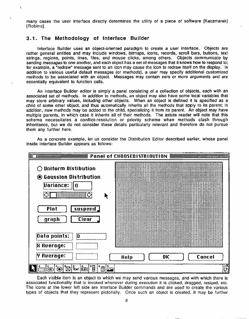
As a concrete example, let us consider the Distribution Editor described earlier, whose panelinside Interface Builder appears as follows:
ED ________ Panel of CHOOSEDISTFIIBUTION __________
0 Uniform Distibution
) Gaussian Distribution
Lariance ~• ~ r a c:................................... O
Plot suspend
graph Clear
Data points: ý0
............... ........ f .............................. ......... .H Average:
:Y fluerage:.. _ _............... .. , ....: :.............
Help 7 OK ) ( Cancel J
Each visible item is an object to which we may send various messages, and with which there isassociated functionality that is invoked whenever during execution it is clicked, dragged, resized, etc.The icons at the lower left side are Interface Builder commands and are used to create the varioustypes of objects that they represent pictorially. Once such an object is created, it may be further
8
il--]• Panel of CHOOSEDISTRIBUTION
modified, resized, and redefined.
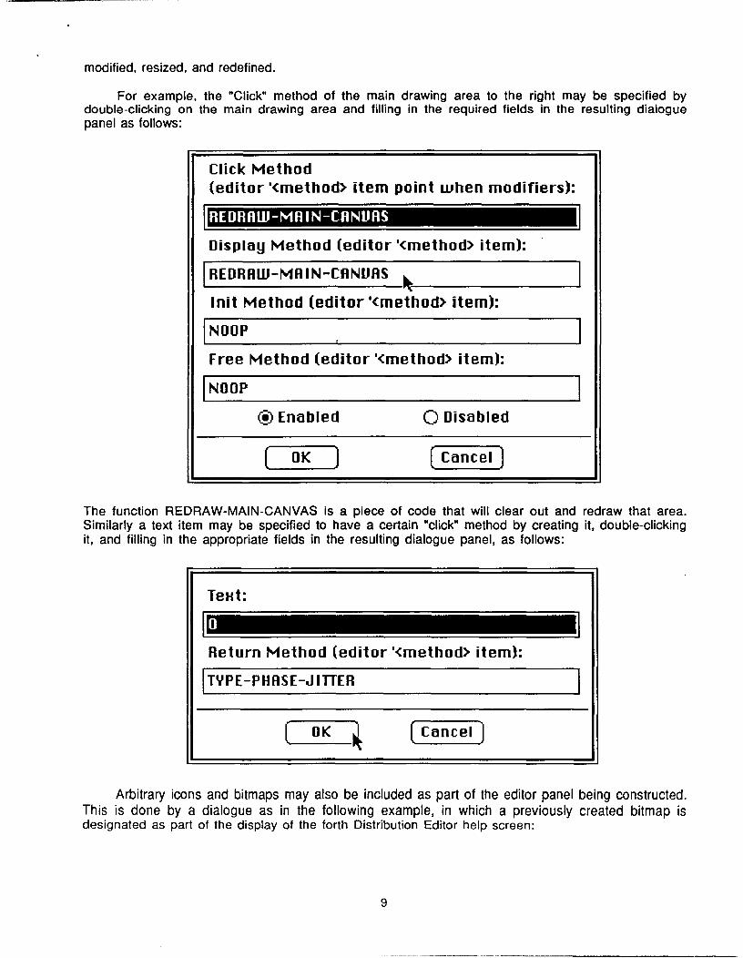
For example, the "Click" method of the main drawing area to the right may be specified bydouble-clicking on the main drawing area and filling in the required fields in the resulting dialoguepanel as follows:
Click Method
(editor '<method> item point when modifiers):
Display Method (editor '<method> item):
IREDRAW-MAIN-CANUAS
Init Method (editor '<method> item):
NOOP
Free Method (editor '<method> item):
NOaP
® En�ibIed 0 Diso bledOK (CancelT
The function REDRAW-MAIN-CANVAS is a piece of code that will clear out and redraw that area.Similarly a text item may be specified to have a certain "click" method by creating it, double-clickingit, and filling in the appropriate fields in the resulting dialogue panel, as follows:
Arbitrary icons and bitmaps may also be included as part of the editor panel being constructed.This is done by a dialogue as in the following example, in which a previously created bitmap isdesignated as part of the display of the forth Distribution Editor help screen:
9
TeHt:
I -Return Method (editor '<method> item):
TYPE-PHASE-JITTER
0IOK Cancel
@ Enabled 0 Disabled
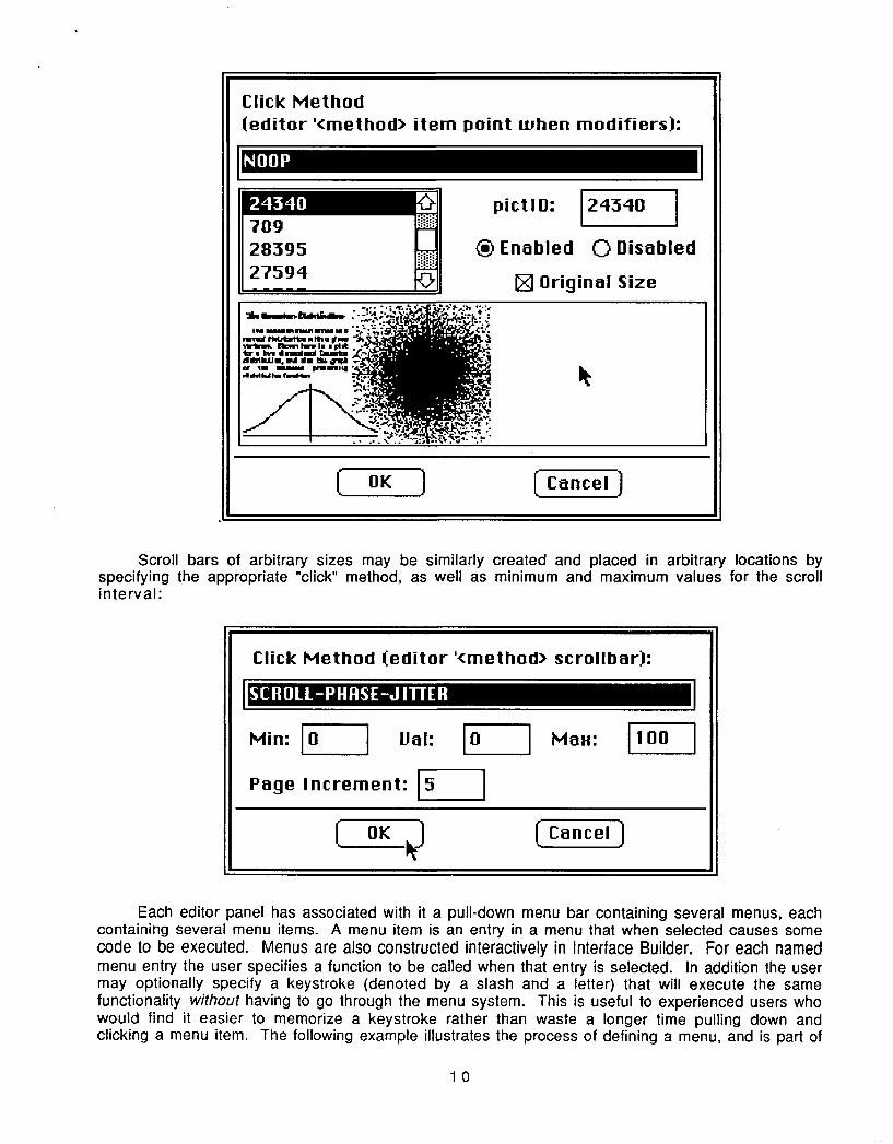
Scroll bars of arbitrary sizes may be similarly created and placed in arbispecifying the appropriate "click" method, as well as minimum and maximum vainterval:
ary locations byes for the scroll
Each editor panel has associated with it a pull-down menu bar containing several menus, eachcontaining several menu items. A menu item is an entry in a menu that when selected causes somecode to be executed. Menus are also constructed interactively in Interface Builder. For each namedmenu entry the user specifies a function to be called when that entry is selected. In addition the usermay optionally specify a keystroke (denoted by a slash and a letter) that will execute the samefunctionality without having to go through the menu system. This is useful to experienced users whowould find it easier to memorize a keystroke rather than waste a longer time pulling down andclicking a menu item. The following example illustrates the process of defining a menu, and is part of
10
Click Method(editor '<method> item point when modifiers):
'IN.
pictID: 124340
28395 M. ® Enabled 0 Disabled27594 l0 Original Size
N•W IN ý N Ui I I,Gd.4hi1 W.ft
Click Method (editor '<method> scrollbar):
IS RLL PH RS- UTE
Min: Val: 0 Ma.: jjooJPage Increment: IJ
L OK Cancel]
I
OK j ( Cancel
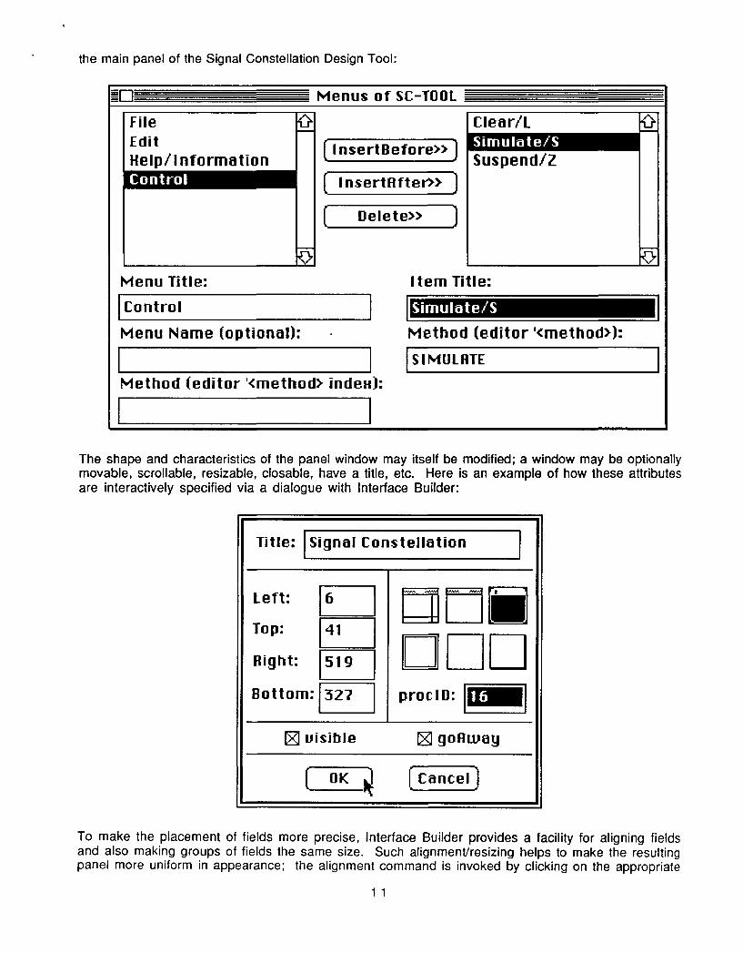
the main panel of the Signal Constellation Design Tool:
FileEditHelp / Information
Menu Title:
Clear/L
InsertBefore»
I nsertFlfter>>
Delete>>
Control
Menu Name (optional):
Method (editor '<method> indeH):
Suspend/Z
Item Title:
Method (editor '<method>):
SI MULATE
The shape and characteristics of the panel window may itself be modified; a window may be optionallymovable, scrollable, resizable, closable, have a title, etc. Here is an example of how these attributesare interactively specified via a dialogue with Interface Builder:
Left: K 1 r flTnn a I
Title: I Signal Constellation I
.1 __ __
IRight: ±519 1 l]Bottom:f327 procID:
v visible ] goRway
L_ OK 1 Cancel]
To make the placement of fields more precise, Interface Builder provides a facility for aligning fieldsand also making groups of fields the same size. Such alignment/resizing helps to make the resultingpanel more uniform in appearance; the alignment command is invoked by clicking on the appropriate
11
MIoS
T
Simulate/SI
Menus of SC-TOOL
I I
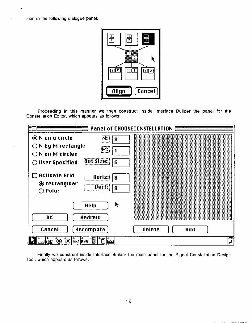
icon in the following dialogue panel:
Proceeding in this manner we then construct inside Interface Builder the panel for theConstellation Editor, which appears as follows:
* N on a circle
o N by M rectangle
o N on M circles
o User Specified
E-] Actiuate Grid* rectangular0 Polar
ot ize: 1 I
Horiz::
Vert:ELEL
Help
Redraw
[-Reompute Delete--- Add
Finally we construct inside Interface Builder the main panel for the Signal Constellation DesignTool, which appears as follows:
12
Cancel
Panel of CHOOSECONSTELLATION
0nK
cancel
fL ED TD Te ED 6ýi1+ 1+(ý)1+01+Xt1+ 1+01+01+ 1 121
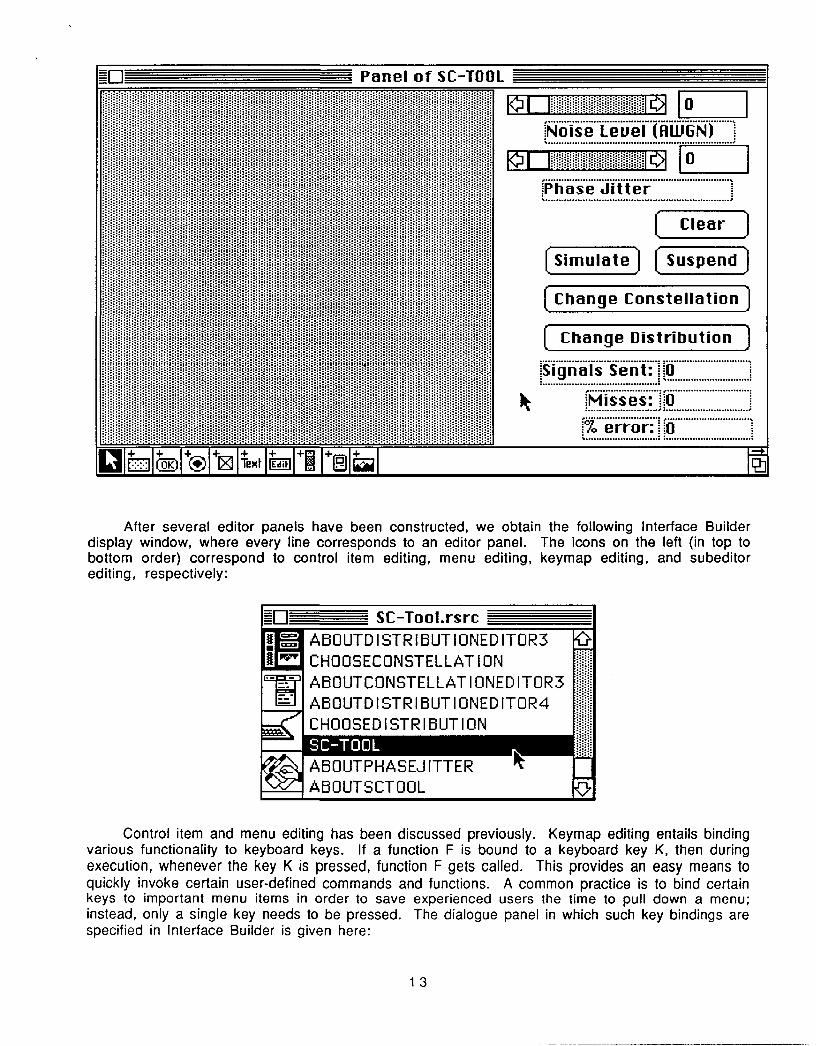
After several editor panels have been constructed, we obtain the following Interface Builderdisplay window, where every line corresponds to an editor panel. The icons on the left (in top tobottom order) correspond to control item editing, menu editing, keymap editing, and subeditorediting, respectively:
=--[ SC-Tool.rsrcif ABOUTD I STR IBUT IONED ITOR3
ti CHOOSECONSTELLATION
SABOUTCONSTELLAT I ONED ITOR3
A BO0UT D ISTR I BUTIO0N ED I TOR 4SCHOOSEDISTRIBUTION M
'S ABOUTSCTOOL }
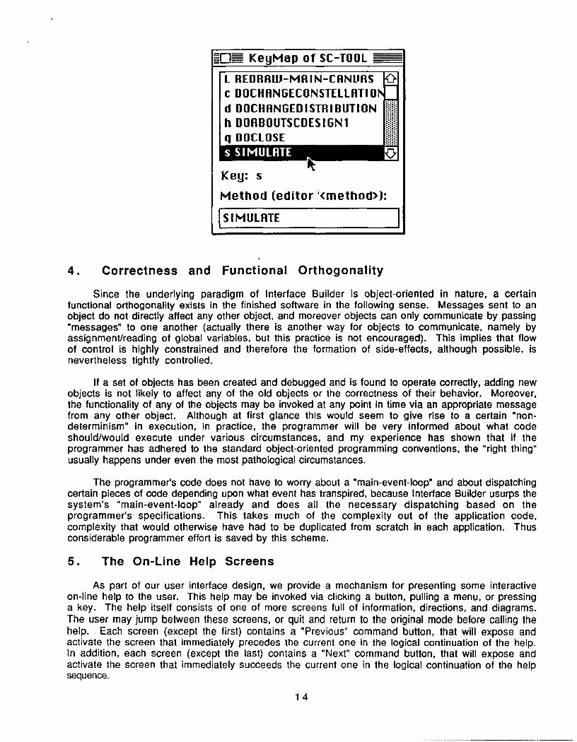
Control item and menu editing has been discussed previously. Keymap editing entails bindingvarious functionality to keyboard keys. If a function F is bound to a keyboard key K, then duringexecution, whenever the key K is pressed, function F gets called. This provides an easy means toquickly invoke certain user-defined commands and functions. A common practice is to bind certainkeys to important menu items in order to save experienced users the time to pull down a menu;instead, only a single key needs to be pressed. The dialogue panel in which such key bindings arespecified in Interface Builder is given here:
13
.. ...........•.
iPhase Jitter
[Clear]
(Sim late Suspend)
Change Constellation
Change Distribution
................ ...............................
Misses 0.M...... ................. ...............................e ri.e rror": O
K=IM KeyMap of SC-TOOL
4. Correctness and Functional Orthogonality
Since the underlying paradigm of Interface Builder is object-oriented in nature, a certainfunctional orthogonality exists in the finished software in the following sense. Messages sent to anobject do not directly affect any other object, and moreover objects can only communicate by passing"messages" to one another (actually there is another way for objects to communicate, namely byassignment/reading of global variables, but this practice is not encouraged). This implies that flowof control is highly constrained and therefore the formation of side-effects, although possible, isnevertheless tightly controlled.
If a set of objects has been created and debugged and is found to operate correctly, adding newobjects is not likely to affect any of the old objects or the correctness of their behavior. Moreover,the functionality of any of the objects may be invoked at any point in time via an appropriate messagefrom any other object. Although at first glance this would seem to give rise to a certain "non-determinism" in execution, in practice, the programmer will be very informed about what codeshould/would execute under various circumstances, and my experience has shown that if theprogrammer has adhered to the standard object-oriented programming conventions, the "right thing"usually happens under even the most pathological circumstances.
The programmer's code does not have to worry about a "main-event-loop" and about dispatchingcertain pieces of code depending upon what event has transpired, because Interface Builder usurps thesystem's "main-event-loop" already and does all the necessary dispatching based on theprogrammer's specifications. This takes much of the complexity out of the application code,complexity that would otherwise have had to be duplicated from scratch in each application. Thusconsiderable programmer effort is saved by this scheme.
5. The On-Line Help Screens
As part of our user interface design, we provide a mechanism for presenting some interactiveon-line help to the user. This help may be invoked via clicking a button, pulling a menu, or pressinga key. The help itself consists of one of more screens full of information, directions, and diagrams.The user may jump between these screens, or quit and return to the original mode before calling thehelp. Each screen (except the first) contains a "Previous" command button, that will expose andactivate the screen that immediately precedes the current one in the logical continuation of the help.In addition, each screen (except the last) contains a "Next" command button, that will expose andactivate the screen that immediately succeeds the current one in the logical continuation of the helpsequence.
14
L REDRAW-MAIN-CANUASc DOCHANGECONSTELLATIO1d DOCHANGEDISTRIBUTIONh DOFIBOUTSCDESIGNIq DOCLOSE
W I1
Key: s
Method (editor '<method>):
SSIMULATE
E-- L --
Having some on-line help is essential in many applications and often saves considerable (manuallook-up) time for the user, especially if the help is also crossed referenced or indexed in somemanner. A good example of useful on-line help facilities is contained in the MicroSoft Word 3.01 textprocessing program.
5.1. On-Line Help Screens for Signal Constellation Design
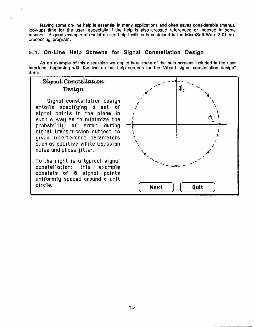
As an example of this discussion we depict here some of the help screens included in the userinterface, beginning with the two on-line help screens for the "About signal constellation design"item:
a a�r"I
Stunoi Lonsteulatton -- ,Dlesig~n
/
Signal constellation designentails specifying a set of /signal points in the plane .insuch a way as to minimize theprobability of error during tosignal transmission subject togiven interference parameterssuch as additive white Gaussiannoise and phase jitter.
To the right is a typical signal N
I-
--
_
II
I-I
15
constellation; this exampleconsists of 8 signal pointsuniformly spaced around a unitcircle. L Next Quit
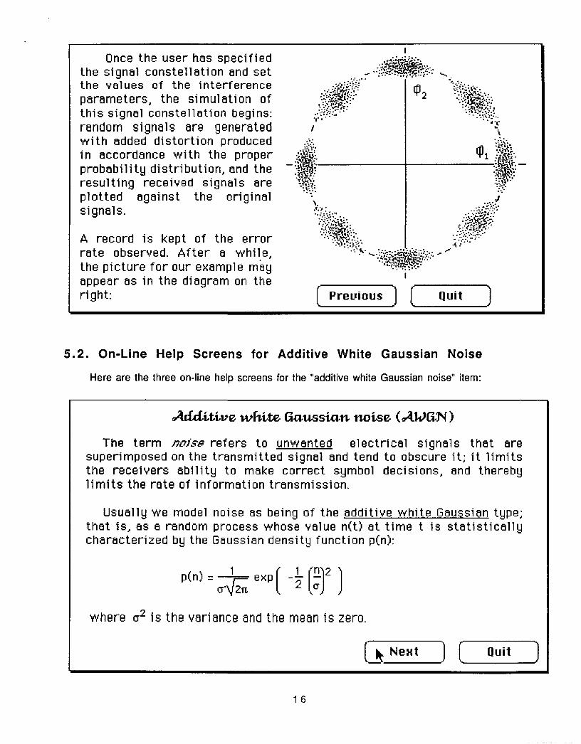
5.2. On-Line Help Screens for Additive White Gaussian Noise
Here are the three on-line help screens for the "additive white Gaussian noise" item:
16
Once the user has specifiedthe signal constellation and setthe values of the interferenceparameters, the simulation ofthis signal constellation begins:random signals are generatedwith added distortion producedin accordance with the properprobability distribution, and theresulting received signals areplotted against the originalsignals.
A record is kept of the errorrate observed. After a while,the picture for our example mayappear as in the diagram on theright:
Acditive white Gaussian noise (AWaN)
The term noise refers to unwanted electrical signals that aresuperimposed on the transmitted signal and tend to obscure it; it limitsthe receivers ability to make correct symbol decisions, and therebylimits the rate of information transmission.
Usually we model noise as being of the additive white Gaussian type;that is, as a random process whose value n(t) at time t is statisticallycharacterized by the Gaussian density function p(n):
p(n) = Qr exp ( __ (9I2J
where y2 is the variance and the mean is zero.
A_ý Nt ( Quith
I
IPrevious Quit
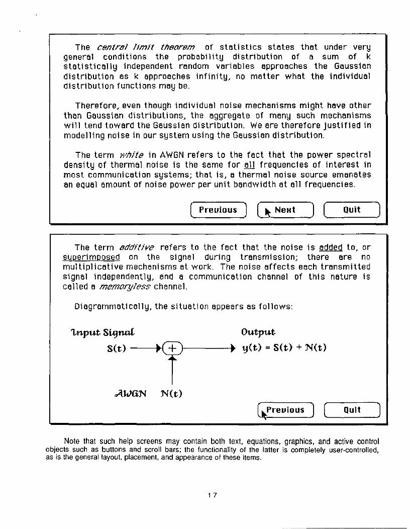
The central limit theorem of statistics states that under verygeneral conditions the probability distribution of a sum of kstatistically independent random variables approaches the Gaussiandistribution as k approaches infinity, no matter what the individualdistribution functions may be.
Therefore, even though individual noise mechanisms might have otherthan Gaussian distributions, the aggregate of many such mechanismswill tend toward the Gaussian distribution. We are therefore justified inmodelling noise in our system using the Gaussian distribution.
The term white in AWGN refers to the fact that the power spectraldensity of thermal noise is the same for all frequencies of interest inmost communication systems; that is, a thermal noise source emanatesan equal amount of noise power per unit bandwidth at all frequencies.
cPrevious Next CZ Quit
The term additive refers to the fact that the noise is added to, orsuperimposed on the signal during transmission; there are nomultiplicative mechanisms at work. The noise affects each transmittedsignal independently, and a communication channel of this nature iscalled a memory/ess channel.
Diagrammatically, the situation appears as follows:
Input Sigýnd
S(t)
Output
y(t) = S(t) + N(t)
AWGN N(t)
•Preuiaus ! = Quit
Note that such help screens may contain both text, equations, graphics, and active controlobjects such as buttons and scroll bars; the functionality of the latter is completely user-controlled,as is the general layout, placement, and appearance of these items.
17
5.3. On-Line Help Screens for Distribution Editor
Here are the four on-line help screens for the Distribution Editor:
The Probbtbility Distribution Eittor
0 Uniform Distibution
® Gaussian Distribution
Dariance: I46
® Uniform Distibution
0 Gaussian Distribution
Interu.a: i
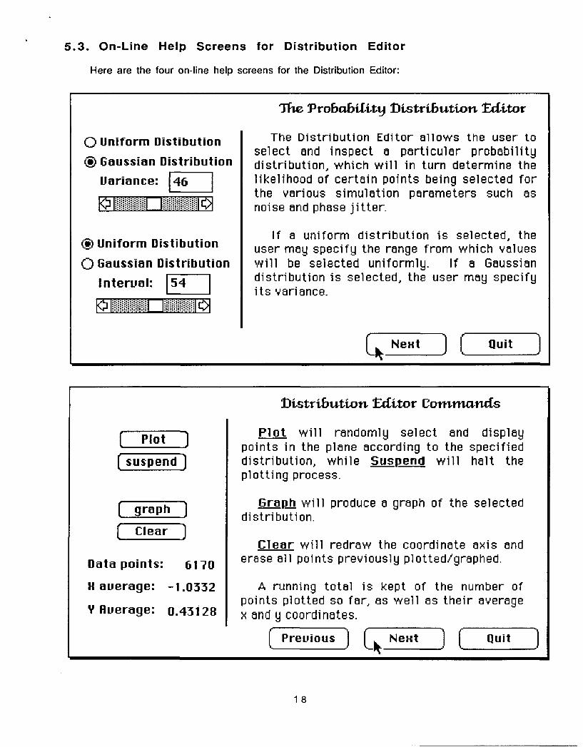
The Distribution Editor allows the user toselect and inspect a particular probabilitydistribution, which will in turn determine thelikelihood of certain points being selected forthe various simulation parameters such asnoise and phase jitter.
If a uniform distribution is selected, theuser may specify the range from which valueswill be selected uniformly. If a Gaussiandistribution is selected, the user may specifyits variance.
C Quit
li-stribuition Editor Commands
Plot :
suspend I
graph J
clear _
Data points:
H average:
6170
-1.0332
V fluerage: 0.43128
Plot willpoints in thedistribution,plotting proce
randomly select andplane according to thewhile Suspend willss.
displayspecifiedhalt the
Graph will produce a graph of the selecteddistribution.
Clear will redraw theerase all points previously
coordinate axis andplotted/graphed.
A running total is kept of the number ofpoints plotted so far, as well as their averagex and y coordinates.
J Previous L 3 Next Quit
18
[1ý Nextit
T1w Gaussian Disi
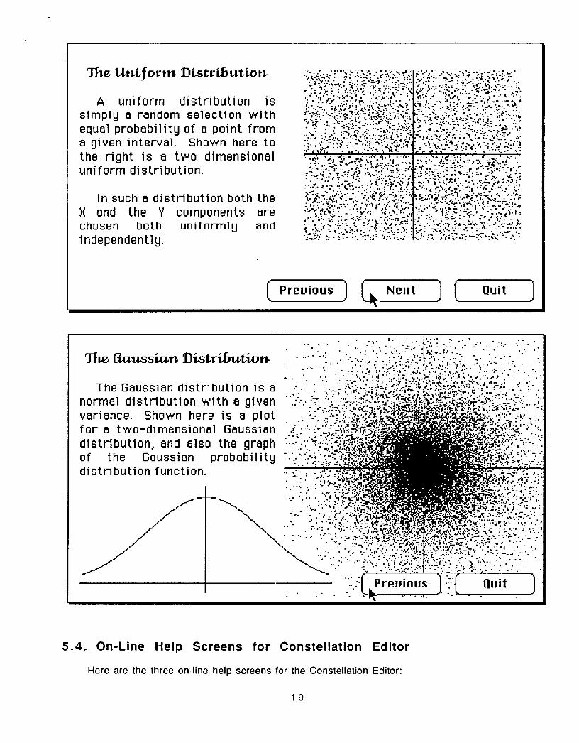
The Gaussian distrnormal distribution vvariance. Shown herfor a two-dimensiondistribution, and alswof the Gaussiandistribution function.
Lribution .... ": " .' . " •• " -" • "". "4." • • ;1 ° _ Z=.t_ .. . ... t:'4 .. .
ibution is aith a given
e is a plotal Gaussiano the graphprobability -
5.4. On-Line Help Screens for Constellation Editor
Here are the three on-line help screens for the Constellation Editor:
19
The UniJorn Distribution
A uniform distribution issimply a random selection withequal probability of a point froma given interval. Shown here tothe right is a two dimensionaluniform distribution.
In such a distribution both theX and the Y components arechosen both uniformly andindependently.
[ -Quit[4 FNext
.o .
.•." "•.
Previous Quit
SPrevious
0 N on a circle
N bu
N on
M rectangleM circles
o User Specified
N:
°: I
Dot Size: fl
I
[KNext
20
0
Constellation Editor Commands
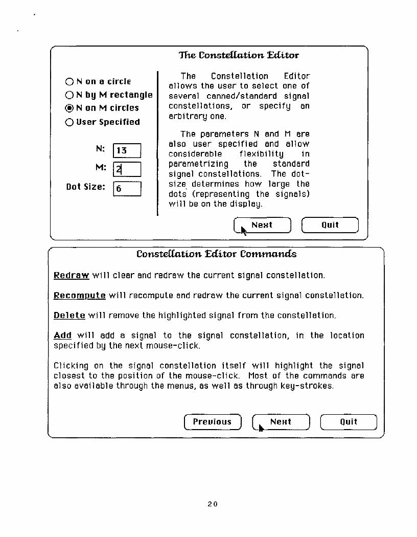
Redraw will clear and redraw the current signal constellation.
Recompute will recompute and redraw the current signal constellation.
Delete will remove the highlighted signal from the constellation.
Add will add a signal to the signal constellation, in the locationspecified by the next mouse-click.
Clicking on the signal constellation itself will highlight the signalclosest to the position of the mouse-click. Most of the commands arealso available through the menus, as well as through key-strokes.
Quit
J
The Constedation Editor
The Constellation Editorallows the user to select one ofseveral canned/standard signalconstellations, or specify anarbitrary one.
The parameters N and M arealso user specified and allowconsiderable flexibility inparametrizing the standardsignal constellations. The dot-size determines how large thedots (representing the signals)will be on the display.
S Quit
SPrevious LbNext )
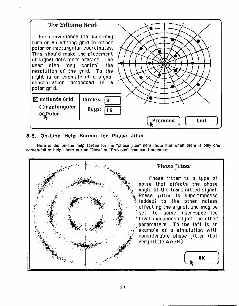
The Editingu arid
For convenience the user mayturn on an editing grid in eitherpolar or rectangular coordinates.This should make the placementof signal dots more precise. Theuser also may control theresolution of the grid. To theright is an example of a signalconstellation embedded in apolar grid.
Circles: _
Rayrs :
5.5. On-Line Help Screen for Phase Jitter
Here is the on-line help screen for the "phase jitter" item (note that when there is only onescreen-full of help, there are no "Next" or "Previous" command buttons):
21
Pfiase Jitter
Phase jitter is a type ofnoise that affects the phaseangle of the transmitted signal.Phase jitter is superimposed(added) to the other noisesaffecting the signal, and may beset to some user-specifiedlevel independently of the otherparameters. To the left is anexample of a simulation withconsiderable phase jitter (butvery little AWGN.)
Liizz
Z fictivate Grid
0 rectangularn, Polar
revious
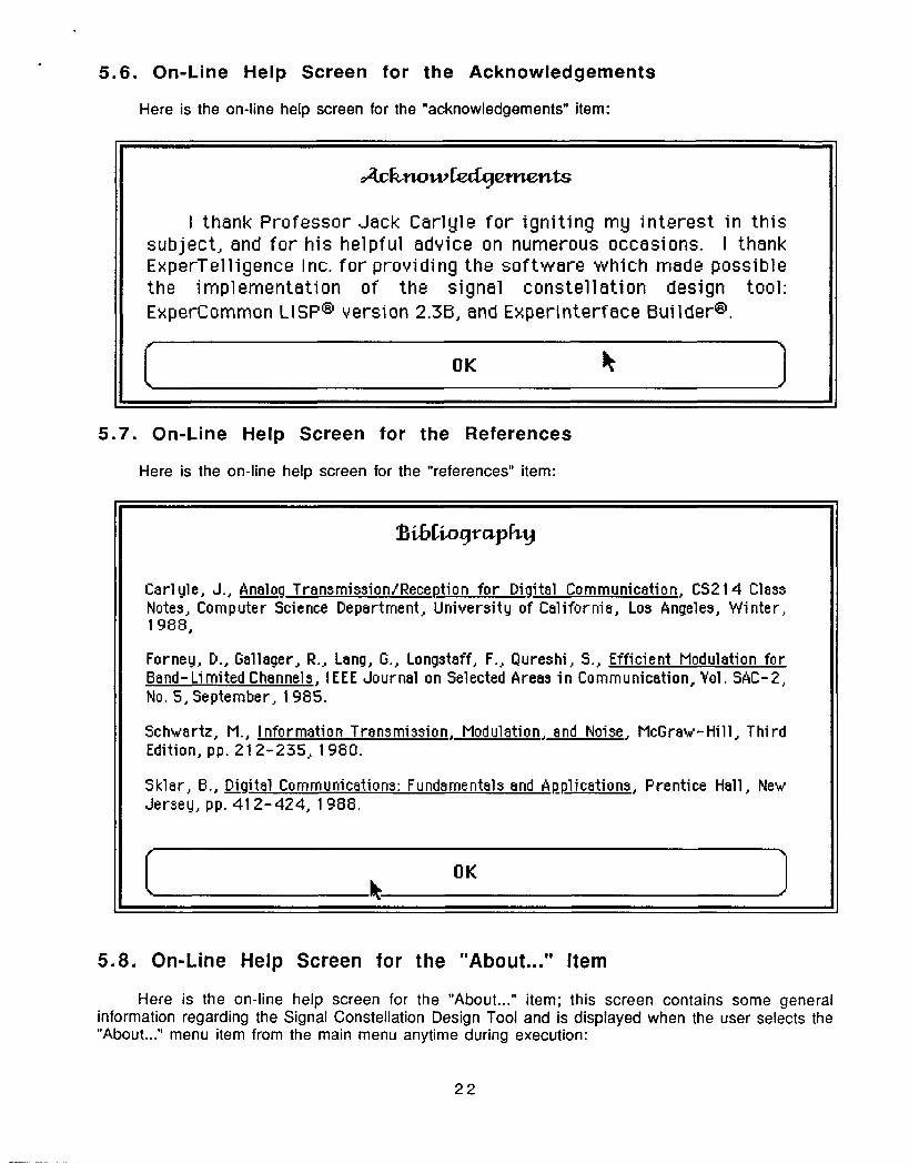
5.6. On-Line Help Screen for the Acknowledgements
Here is the on-line help screen for the "acknowledgements" item:
5.7. On-Line Help Screen for the References
Here is the on-line help screen for the "references" item:
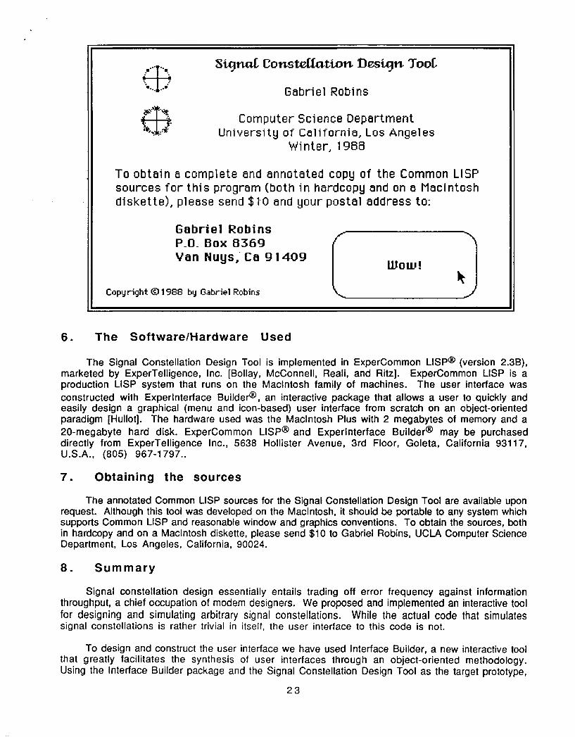
5.8. On-Line Help Screen for the "About..." Item
Here is the on-line help screen for the "About..." item; this screen contains some generalinformation regarding the Signal Constellation Design Tool and is displayed when the user selects the"About..." menu item from the main menu anytime during execution:
22
Acknowledgements
I thank Professor Jack Carlyle for igniting my interest in thissubject, and for his helpful advice on numerous occasions. I thankExperTelligence Inc. for providing the software which made possiblethe implementation of the signal constellation design tool:ExperCommon LISP® version 2.3B, and Experinterface Builder®.
I ~OKk
BibligraphFyJ
Carlyle, J., Lnalog Transmission/Reception for Digital Communication, CS214 ClassNotes, Computer Science Department, University of California, Los Angeles, Winter,1988,
Forney, D., Gallager, R., Lang, G., Longstaff, F., Qureshi, S., Efficient Modulation forBand-Limited Channels, IEEE Journal on Selected Areas in Communication, Yol. SAC-2,No. 5, September, 1985.
Schwartz, M., Information Transmission, Modulation, and Noise, McGraw-Hill, ThirdEdition, pp. 212-235, 1980.
Sklar, B., Digital Communications: Fundamentals and Applications, Prentice Hall, NewJersey, pp. 412-424, 1988.
6. The Software/Hardware Used
The Signal Constellation Design Tool is implemented in ExperCommon LISP® (version 2.3B),marketed by ExperTelligence, Inc. [Bollay, McConnell, Reali, and Ritz]. ExperCommon LISP is aproduction LISP system that runs on the Macintosh family of machines. The user interface wasconstructed with Experlnterface Builder@, an interactive package that allows a user to quickly andeasily design a graphical (menu and icon-based) user interface from scratch on an object-orientedparadigm [Hullot]. The hardware used was the Macintosh Plus with 2 megabytes of memory and a20-megabyte hard disk. ExperCommon LISP@ and Experlnterface Builder@ may be purchaseddirectly from ExperTelligence Inc., 5638 Hollister Avenue, 3rd Floor, Goleta, California 93117,U.S.A., (805) 967-1797..
7. Obtaining the sources
The annotated Common LISP sources for the Signal Constellation Design Tool are available uponrequest. Although this tool was developed on the Macintosh, it should be portable to any system whichsupports Common LISP and reasonable window and graphics conventions. To obtain the sources, bothin hardcopy and on a Macintosh diskette, please send $10 to Gabriel Robins, UCLA Computer ScienceDepartment, Los Angeles, California, 90024.
8. Summary
Signal constellation design essentially entails trading off error frequency against informationthroughput, a chief occupation of modem designers. We proposed and implemented an interactive toolfor designing and simulating arbitrary signal constellations. While the actual code that simulatessignal constellations is rather trivial in itself, the user interface to this code is not.
To design and construct the user interface we have used Interface Builder, a new interactive toolthat greatly facilitates the synthesis of user interfaces through an object-oriented methodology.Using the Interface Builder package and the Signal Constellation Design Tool as the target prototype,
23
Signnl Consteffation Dlesig3n To
Gabriel Robins
Computer Science DepartmentUniversity of California, Los Angeles
Winter, 1988
To obtain a complete and annotated copy of the Common LISPsources for this program (both in hardcopy and on a Macintoshdiskette), please send $10 and your postal address to:
Gabriel RobinsP.O. Box 0369Van Nuys, Ca 91409 Wow!
Copyright (1 1988 by Gabriel Robins
we showed how an order-of-magnitude improvement can be achieved in the effort required to producea complex user interface.
We hope that we have helped to dispel some of the mystique surrounding user interface synthesison state-of-the-art workstations by showing that given the proper tools and methodology, thesynthesis of complex user interfaces could be rather trivial. In particular, designing andimplementing the user interface specified here took only a few days, and that includes the overhead toread the user manuals and learn (from scratch) how to use the software.
9. Acknowledgements
I thank Professor Jack Carlyle for igniting my interest in this subject, and for his helpfuladvice on numerous occasions. I thank ExperTelligence Inc. for providing the software which madepossible the implementation of the Signal Constellation Design Tool.
10. Bibliography
Bollay, D., McConnell, J., Reali, R., Ritz, D., ExperCommon LISP Documentation: Volume I. II. and Ill,The ExperTelligence Press, Santa Barbara, California, 1987.
Carlyle, J., Analoa Transmission/Reception for Digital Communication, CS214 Class Notes, ComputerScience Department, University of California, Los Angeles, Winter, 1988,
Forney, D., Gallager, R., Lang, G., Longstaff, F., Qureshi, S., Efficient Modulation for Band-LimitedChannels, IEEE Journal on Selected Areas in Communication, Vol. SAC-2, No. 5, September, 1985.
Goodman, D., The Complete HyperCard Handbook, Bantham Books, New York, 1987.
Hullot, J., Experlnterface Builder Documentation, The ExperTelligence Press, Santa Barbara,California, 1987.
Kaczmarek, T., Mark, W., & Wilczynski, D., The CUE Proiect, Proceedings of SoftFair, July, 1983.
Robins, G. The ISI Grapher: A Portable Tool for Displaying Graphs Pictorially, Invited Talk inSymboliikka '87, Helsinki, Finland, August, 17-18, 1987. Reprinted in Multicomputer Vision,Levialdi, S., Chapter 12, Academic Press, London, 1988.
Schwartz, M., Information Transmission. Modulation. and Noise, McGraw-Hill, Third Edition, pp.212-235, 1980.
Sklar, B., Digital Communications: Fundamentals and Applications, Prentice Hall, New Jersey, pp.412-424, 1988.
24