siemens ag: simatic s7 ethernetasutp.org/simatic_s7_ethernet_sies7tcp.pdfsiemens ag simatic s7...
TRANSCRIPT

1
Siemens AG
SIMATIC S7 Ethernet Driver
1 System Configuration....................................................................................................... 3
2 External Device Selection ................................................................................................ 6
3 Communication Settings .................................................................................................. 7
4 Setup Items .................................................................................................................... 22
5 Supported Device Addresses......................................................................................... 31
6 Device Code and Address Code.................................................................................... 41
7 Error Messages.............................................................................................................. 42
SIMATIC S7 Ethernet Driver
GP-Pro EX Device/PLC Connection Manual 2
Introduction
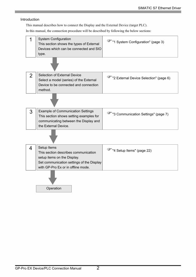
This manual describes how to connect the Display and the External Device (target PLC).
In this manual, the connection procedure will be described by following the below sections:
1 System Configuration
This section shows the types of External
Devices which can be connected and SIO
type.
"1 System Configuration" (page 3)
2 Selection of External Device
Select a model (series) of the External
Device to be connected and connection
method.
"2 External Device Selection" (page 6)
3 Example of Communication Settings
This section shows setting examples for
communicating between the Display and
the External Device.
"3 Communication Settings" (page 7)
4 Setup Items
This section describes communication
setup items on the Display.
Set communication settings of the Display
with GP-Pro Ex or in offline mode.
"4 Setup Items" (page 22)
Operation
SIMATIC S7 Ethernet Driver
GP-Pro EX Device/PLC Connection Manual 3
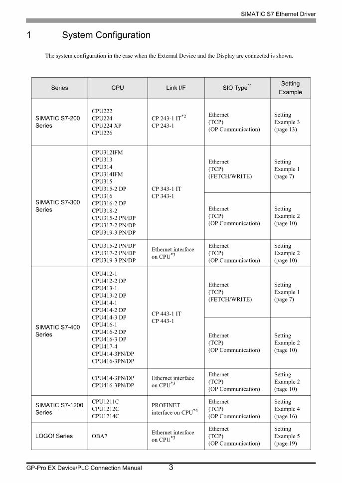
1 System Configuration
The system configuration in the case when the External Device and the Display are connected is shown.
Series CPU Link I/F SIO Type*1 Setting
Example
SIMATIC S7-200Series
CPU222CPU224CPU224 XPCPU226
CP 243-1 IT*2
CP 243-1
Ethernet(TCP)(OP Communication)
Setting Example 3 (page 13)
SIMATIC S7-300Series
CPU312IFMCPU313CPU314CPU314IFMCPU315CPU315-2 DPCPU316CPU316-2 DPCPU318-2CPU315-2 PN/DPCPU317-2 PN/DPCPU319-3 PN/DP
CP 343-1 ITCP 343-1
Ethernet(TCP)(FETCH/WRITE)
Setting Example 1 (page 7)
Ethernet(TCP)(OP Communication)
Setting Example 2 (page 10)
CPU315-2 PN/DPCPU317-2 PN/DPCPU319-3 PN/DP
Ethernet interface on CPU*3
Ethernet(TCP)(OP Communication)
Setting Example 2 (page 10)
SIMATIC S7-400Series
CPU412-1CPU412-2 DPCPU413-1CPU413-2 DPCPU414-1CPU414-2 DPCPU414-3 DPCPU416-1CPU416-2 DPCPU416-3 DPCPU417-4CPU414-3PN/DPCPU416-3PN/DP
CP 443-1 ITCP 443-1
Ethernet(TCP)(FETCH/WRITE)
Setting Example 1 (page 7)
Ethernet(TCP)(OP Communication)
Setting Example 2 (page 10)
CPU414-3PN/DPCPU416-3PN/DP
Ethernet interface on CPU*3
Ethernet(TCP)(OP Communication)
Setting Example 2 (page 10)
SIMATIC S7-1200Series
CPU1211CCPU1212CCPU1214C
PROFINET interface on CPU*4
Ethernet(TCP)(OP Communication)
Setting Example 4 (page 16)
LOGO! Series OBA7Ethernet interface on CPU*3
Ethernet(TCP)(OP Communication)
Setting Example 5 (page 19)

SIMATIC S7 Ethernet Driver
GP-Pro EX Device/PLC Connection Manual 4
*1 OP Communication has a larger address range of usable devices as that of FETCH/WRITE, so we recommend use of OP Communication.
"5 Supported Device Addresses" (page 31)
*2 CP 243-1 IT and CP 243-1 can use the version of CPU above Rel.1.20.
*3 The Ethernet interface in the CPU only supports OP Communication. FETCH/WRITE cannot be used.
*4 The PROFINET interface in the CPU only supports OP Communication. FETCH/WRITE cannot be used.

SIMATIC S7 Ethernet Driver
GP-Pro EX Device/PLC Connection Manual 5
Connection Configuration
• 1:1 Connection
• 1:n Connection
• n:1 Connection
The number of connectable Displays depends on the External Device.
• The number of connectable Display depends on the External Device.
Please refer to the External Device manual for more details.
• The following limitations apply when using the LOGO! series:
• 1:n connections require a network switch.
• n:1 connection is not supported.
• You cannot use the Display if the ladder software is online.
HUB
Display External Device
Display External Device External Device
HUB
Max 16 units
Display Display External Device
HUB
Max 32 units

SIMATIC S7 Ethernet Driver
GP-Pro EX Device/PLC Connection Manual 6
2 External Device Selection
Select the External Device to be connected to the Display.
Setup Items Setup Description
Number of Devices/PLCs
Enter an integer from 1 to 4 for the number of series to set.
Manufacturer Select the manufacturer of the External Device to be connected. Select "Siemens AG".
Series
Select a model (series) of the External Device to be connected and connection method. Select "SIMATIC S7 Ethernet".Check the External Device which can be connected in "SIMATIC S7 Ethernet" in system configuration.
"1 System Configuration" (page 3)
Port Select the Display port to be connected to the External Device.
Use System Area
Check this option when you synchronize the system data area of Display and the device (memory) of External Device. When synchronized, you can use the ladder program of External Device to switch the display or display the window on the display.
Cf. GP-Pro EX Reference Manual "LS Area (Direct Access Method Area)"This can also be set in GP-Pro EX or in the Display's offline mode.
Cf. GP-Pro EX Reference Manual "Display Unit (System Area) Settings Guide"Cf. Maintenance/Troubleshooting Manual "Main Unit - System Area Settings"

SIMATIC S7 Ethernet Driver
GP-Pro EX Device/PLC Connection Manual 7
3 Communication Settings
Examples of communication settings of the Display and the External Device, recommended by Pro-face, are
shown.
3.1 Setting Example 1
GP-Pro EX Settings
Communication Settings
To display the setup screen, from the [Project] menu, point to [System Settings] and select [Device/PLC].
SIMATIC S7 Ethernet Driver
GP-Pro EX Device/PLC Connection Manual 8
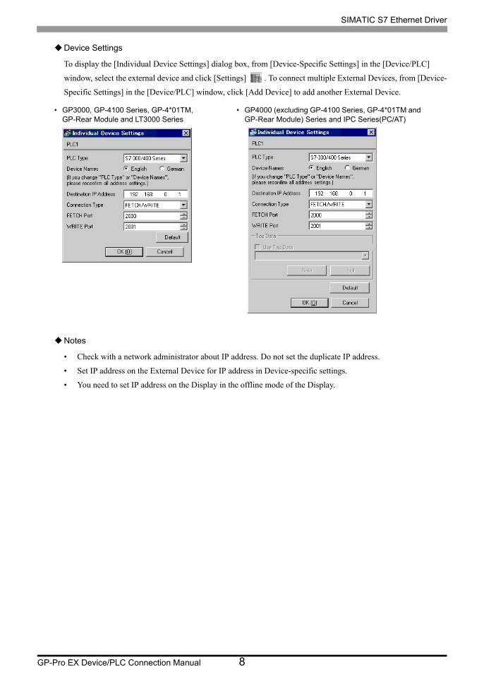
Device Settings
To display the [Individual Device Settings] dialog box, from [Device-Specific Settings] in the [Device/PLC]
window, select the external device and click [Settings] . To connect multiple External Devices, from [Device-
Specific Settings] in the [Device/PLC] window, click [Add Device] to add another External Device.
Notes
• Check with a network administrator about IP address. Do not set the duplicate IP address.
• Set IP address on the External Device for IP address in Device-specific settings.
• You need to set IP address on the Display in the offline mode of the Display.
• GP3000, GP-4100 Series, GP-4*01TM, GP-Rear Module and LT3000 Series
• GP4000 (excluding GP-4100 Series, GP-4*01TM and GP-Rear Module) Series and IPC Series(PC/AT)

SIMATIC S7 Ethernet Driver
GP-Pro EX Device/PLC Connection Manual 9
External Device Settings
Use the FETCH TCP protocol and WRITE TCP protocol so that the Ethernet driver can read and write data for
the External Device. Setting example is shown below. Please refer to the manual of the External Device for more
details.
(1) Select CP343-1/443-1 from hardware configuration menu in the ladder software "STEP 7" by Siemens AG.
When the dialog box is displayed, set [IP address] and [Subnet mask] in the [Parameters] tab.
(2) Start up "NetPro" from "STEP7", and select the CPU to which CP343-1/443-1 is connected. Right-click to
select [Insert New Connection].
(3) Select [TCP connection] for [Type] in the displayed dialog box, and leaving [Unspecified] selected for
[Station], click [OK].
(4) Click the [Options] tab in the displayed dialog box, and select [Fetch passive] in [Mode].
(5) Click the [Address] tab, and enter the port No. (FETCH PORT No. Default 2000) Do not set the duplicate port
No.
(6) Click [OK].
(7) Select the CPU again to which CP343-1/443-1 is connected. Right-click to select [Insert New Connection].
(8) Select [TCP connection] for [Type] in the displayed dialog box, and leaving [Unspecified] selected for
[Station], click [OK].
(9) Click the [Options] tab in the displayed dialog box, and select [Write passive] in [Mode].
(10)Select the [Address] tab and enter the port No. (WRITE PORT No. Default 2001) Do not set the duplicate
port No.
(11)Click [OK].
(12)Save the above setting contents and download to the External Device.
Notes
• The FETCH port’s Partner that is set in the ladder software communication setting dialog box must be the
same as the [Port No. (FETCH)] set in the GP-Pro EX communication settings. Likewise, the WRITE port’s
Partner must be the same as the [Port No. (WRITE)].
If each Partner of the FETCH port and the WRITE port is blank, the [Port No.] can be also set to [Auto].
• Check with a network administrator about IP address. Do not set the duplicate IP address.
• The "Keep Alive" feature of Siemens CP Module is not supported. Please set the "Keep Alive" to 0.
• When the Display is turned off and on again during communication with the External Device or is switched to
offline mode and then back to online mode, it may take several tens of seconds before the communication is
resumed.

SIMATIC S7 Ethernet Driver
GP-Pro EX Device/PLC Connection Manual 10
3.2 Setting Example 2
GP-Pro EX Settings
Communication Settings
To display the setup screen, from the [Project] menu, point to [System Settings] and select [Device/PLC].
• Port No. that is set to [Port No. (FETCH)] performs communication in OP Communication. Port
No. that is set to [Port No. (WRITE)] is not used.

SIMATIC S7 Ethernet Driver
GP-Pro EX Device/PLC Connection Manual 11
Device Settings
To display the [Individual Device Settings] dialog box, from [Device-Specific Settings] in the [Device/PLC]
window, select the external device and click [Settings] . To connect multiple External Devices, from [Device-
Specific Settings] in the [Device/PLC] window, click [Add Device] to add another External Device.
Notes
• Check with a network administrator about IP address. Do not set the duplicate IP address.
• Set IP address on the External Device for IP address in Device-specific settings.
• You need to set IP address on the Display in the offline mode of the Display.
• GP3000, GP-4100 Series, GP-4*01TM, GP-Rear Module and LT3000 Series
• GP4000 (excluding GP-4100 Series, GP-4*01TM and GP-Rear Module) Series and IPC Series(PC/AT)

SIMATIC S7 Ethernet Driver
GP-Pro EX Device/PLC Connection Manual 12
External Device Settings
The Communication setting for the External Device is executed using ladder software (STEP 7).
Please refer to the manual of the External Device for more details.
(1) Start up ladder software.
(2) Select [New Project Wizard] of [File] menu and make a project. Set the CPU, Organization Block, and project
name to be used following the instruction provided by the wizard.
(3) Start up Hardware setting.
(4) Select the module to be used from the catalog view and allocate it to the slot of the mounted module number.
(5) After allocating the module, [Property] dialog box is displayed. Set IP address and subnet mask to [Property]
dialog box of the module to be used for communication.
(6) Select [New] from [Subnet] of [Property] dialog box.
(7) Confirm displayed Subnet property and click [OK].
(8) Select Subnet property displayed in [Subnet] of [Property] dialog box. Click [OK] to close [Property] dialog
box.
(9) Select [Save and Compile] from [Station] menu and save the contents of the settings. After saving, end
Hardware setting.
(10)Start up NetPro and download the contents for setting to the External Device. After the download is
completed, reboot the power of the External Device.
Notes
• Check that the CPU rack number and CPU slot number to be used for communication are the same as the GP-
Pro EX setting. If the setting is not the same, communication cannot be conducted.
• Check with a network administrator about IP address. Do not set the duplicate IP address.
• When the Display is turned off and on again during communication with the External Device or is switched to
offline mode and then back to online mode, it may take several tens of seconds before the communication is
resumed.
SIMATIC S7 Ethernet Driver
GP-Pro EX Device/PLC Connection Manual 13
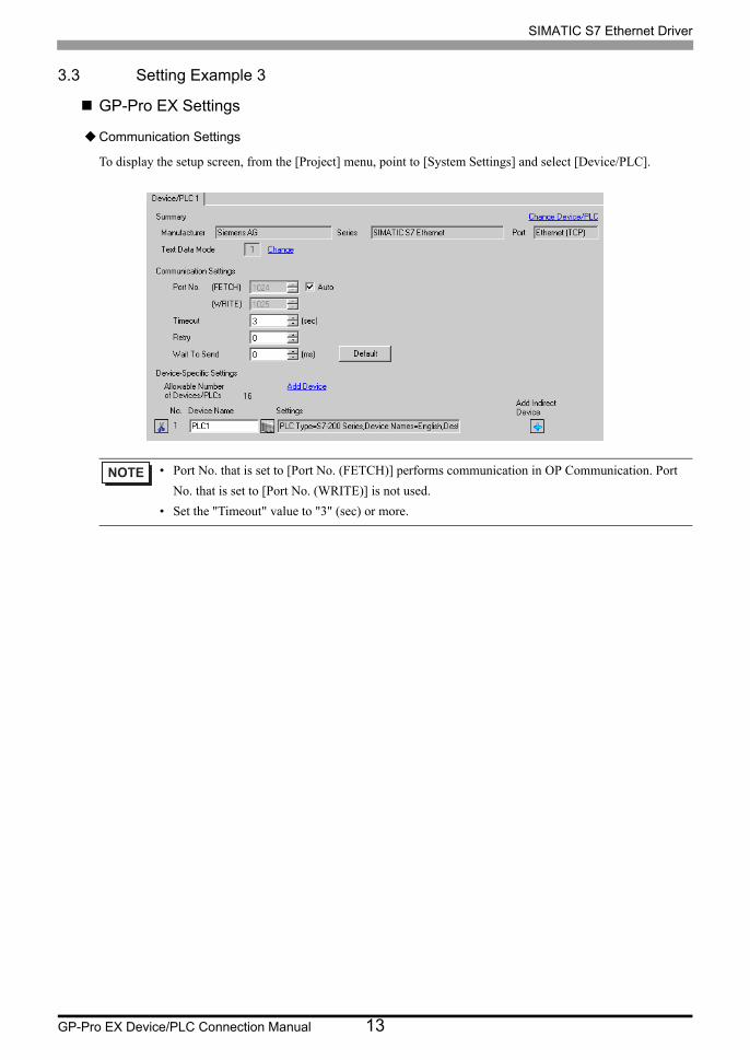
3.3 Setting Example 3
GP-Pro EX Settings
Communication Settings
To display the setup screen, from the [Project] menu, point to [System Settings] and select [Device/PLC].
• Port No. that is set to [Port No. (FETCH)] performs communication in OP Communication. Port
No. that is set to [Port No. (WRITE)] is not used.
• Set the "Timeout" value to "3" (sec) or more.

SIMATIC S7 Ethernet Driver
GP-Pro EX Device/PLC Connection Manual 14
Device Settings
To display the [Individual Device Settings] dialog box, from [Device-Specific Settings] in the [Device/PLC]
window, select the external device and click [Settings] . To connect multiple External Devices, from [Device-
Specific Settings] in the [Device/PLC] window, click [Add Device] to add another External Device.
Notes
• Check with a network administrator about IP address. Do not set the duplicate IP address.
• Set IP address on the External Device for IP address in Device-specific settings.
• You need to set IP address on the Display in the offline mode of the Display.
• GP3000, GP-4100 Series, GP-4*01TM, GP-Rear Module and LT3000 Series
• GP4000 (excluding GP-4100 Series, GP-4*01TM and GP-Rear Module) Series and IPC Series(PC/AT)

SIMATIC S7 Ethernet Driver
GP-Pro EX Device/PLC Connection Manual 15
External Device Settings
Use the ladder software (STEP 7 Micro/Win32) for communication settings of the External Device. Please refer to
the manual of the External Device for details.
(1) Start up the ladder software.
(2) From the [Tool] menu, select [Ethernet Wizard].
(3) Click [Next].
(4) Click [Read Module] to detect the installed Ethernet module.
(5) Enter the [Position] value of the detected module in [Module Position], and then click [Next].
(6) Set [IP Address] and [Subnet Mask], and then click [Next].
(7) Enter "1" (the number of the Display to be connected) in "Number of connections to configure for this
module.", and then click [Next].
(8) Follow the steps below to set the Display, and then click [OK].
• Select "This is a Server Connection" to connect the External Device to the Display.
• In the "Local Properties (Server)" area, select "Accept all connection requests." to allow connections from
all IP addresses.
• In the "Remote Properties (Client)" area, enter "10.00" in "TSAP".
• Clear the "Enable the Keep Alive function for this connection." check box because the Display does not
support KeepAlive.
(9) Click [Next].
(10)To save the module configuration, set the memory address of the External Device, and then click [Next].
(11)Click [Finish].
(12)Click [Yes] for the confirmation message.
(13)Select [Save] from [File], and download the configuration to the External Device.
Notes
• Check with your network administrator about the IP address. Do not duplicate IP addresses.
• The subroutine "ETH0_CTRL" must be called by the ladder program every scan.
• When the Display is turned off and on again during communication with the External Device or is switched to
offline mode and then back to online mode, it may take several tens of seconds before the communication is
resumed.
• The connection number is displayed in this dialog box. If the connection number is "1", for
example, [Connection 1] is displayed.

SIMATIC S7 Ethernet Driver
GP-Pro EX Device/PLC Connection Manual 16
3.4 Setting Example 4
GP-Pro EX Settings
Communication Settings
To display the setup screen, from the [Project] menu, point to [System Settings] and select [Device/PLC].
• Port No. that is set to [Port No. (FETCH)] performs communication in OP Communication. Port
No. that is set to [Port No. (WRITE)] is not used.
• Set the "Timeout" value to "3" (sec) or more.
SIMATIC S7 Ethernet Driver
GP-Pro EX Device/PLC Connection Manual 17
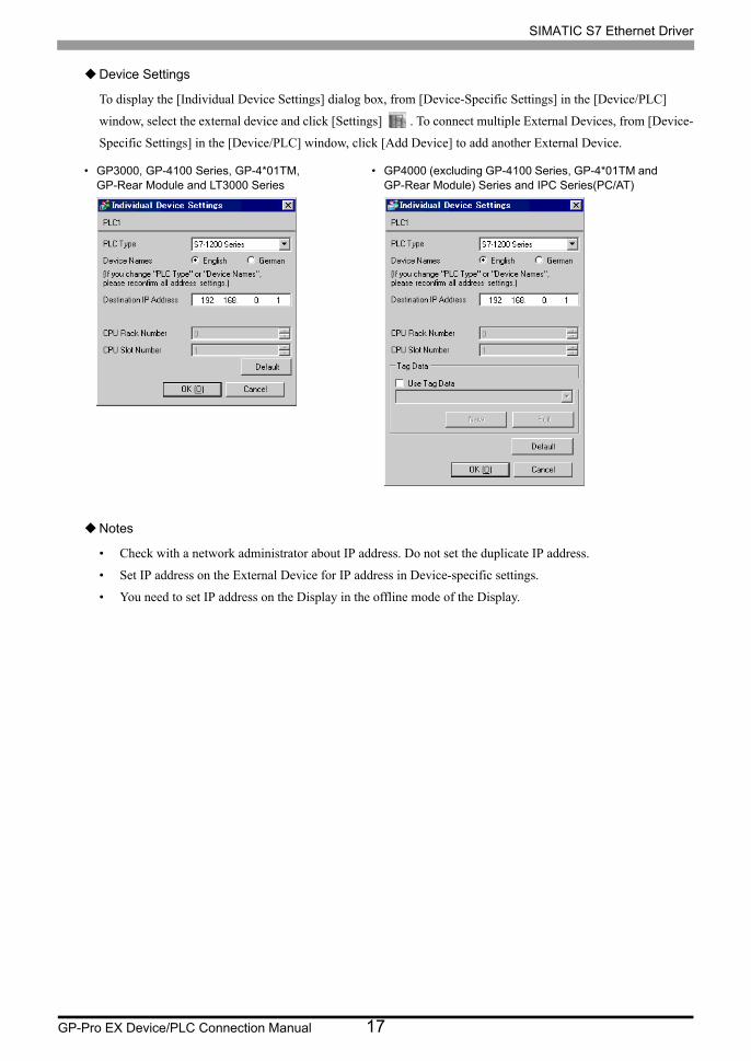
Device Settings
To display the [Individual Device Settings] dialog box, from [Device-Specific Settings] in the [Device/PLC]
window, select the external device and click [Settings] . To connect multiple External Devices, from [Device-
Specific Settings] in the [Device/PLC] window, click [Add Device] to add another External Device.
Notes
• Check with a network administrator about IP address. Do not set the duplicate IP address.
• Set IP address on the External Device for IP address in Device-specific settings.
• You need to set IP address on the Display in the offline mode of the Display.
• GP3000, GP-4100 Series, GP-4*01TM, GP-Rear Module and LT3000 Series
• GP4000 (excluding GP-4100 Series, GP-4*01TM and GP-Rear Module) Series and IPC Series(PC/AT)

SIMATIC S7 Ethernet Driver
GP-Pro EX Device/PLC Connection Manual 18
External Device Settings
Use the ladder software (STEP 7 BASIC) to configure the External Device communication settings. Please refer
to the External Device manual for details.
(1) Start up the ladder software.
(2) Create a project and select the External Device.
(3) Select the PROFINET interface on the CPU and display the setup screen.
(4) Select [Ethernet address] and set up as follows.
(5) Save and transfer the project to the External Device.
Setup Items Setting Value
IP address 192.168.0.1
Subnet mask 255.255.255.0

SIMATIC S7 Ethernet Driver
GP-Pro EX Device/PLC Connection Manual 19
3.5 Setting Example 5
GP-Pro EX Settings
Communication Settings
To display the setup screen, from the [Project] menu, point to [System Settings] and select [Device/PLC].
• Port No. that is set to [Port No. (FETCH)] performs communication in OP Communication. Port
No. that is set to [Port No. (WRITE)] is not used.
• Set the "Timeout" value to "3" (sec) or more.

SIMATIC S7 Ethernet Driver
GP-Pro EX Device/PLC Connection Manual 20
Device Settings
To display the [Individual Device Settings] dialog box, from [Device-Specific Settings] in the [Device/PLC]
window, select the external device and click [Settings] . To connect multiple External Devices, from [Device-
Specific Settings] in the [Device/PLC] window, click [Add Device] to add another External Device.
Notes
• Check with a network administrator about IP address. Do not set the duplicate IP address.
• Set IP address on the External Device for IP address in Device-specific settings.
• You need to set IP address on the Display in the offline mode of the Display.
• GP3000, GP-4100 Series, GP-4*01TM, GP-Rear Module and LT3000 Series
• GP4000 (excluding GP-4100 Series, GP-4*01TM and GP-Rear Module) Series and IPC Series(PC/AT)
SIMATIC S7 Ethernet Driver
GP-Pro EX Device/PLC Connection Manual 21
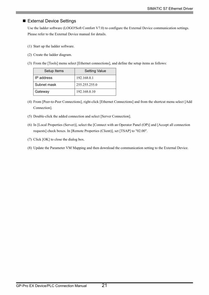
External Device Settings
Use the ladder software (LOGO!Soft Comfort V7.0) to configure the External Device communication settings.
Please refer to the External Device manual for details.
(1) Start up the ladder software.
(2) Create the ladder diagram.
(3) From the [Tools] menu select [Ethernet connections], and define the setup items as follows:
(4) From [Peer-to-Peer Connections], right-click [Ethernet Connections] and from the shortcut menu select [Add
Connection].
(5) Double-click the added connection and select [Server Connection].
(6) In [Local Properties (Server)], select the [Connect with an Operator Panel (OP)] and [Accept all connection
requests] check boxes. In [Remote Properties (Client)], set [TSAP] to "02.00".
(7) Click [OK] to close the dialog box.
(8) Update the Parameter VM Mapping and then download the communication setting to the External Device.
Setup Items Setting Value
IP address 192.168.0.1
Subnet mask 255.255.255.0
Gateway 192.168.0.10
SIMATIC S7 Ethernet Driver
GP-Pro EX Device/PLC Connection Manual 22
4 Setup Items
Set communication settings of the Display with GP-Pro EX or in offline mode of the Display.
The setting of each parameter must be identical to that of External Device.
"3 Communication Settings" (page 7)
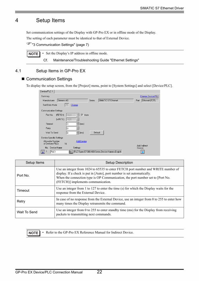
4.1 Setup Items in GP-Pro EX
Communication Settings
To display the setup screen, from the [Project] menu, point to [System Settings] and select [Device/PLC].
• Set the Display’s IP address in offline mode.
Cf. Maintenance/Troubleshooting Guide "Ethernet Settings"
Setup Items Setup Description
Port No.
Use an integer from 1024 to 65535 to enter FETCH port number and WRITE number of display. If a check is put in [Auto], port number is set automatically. When the connection type is OP Communication, the port number set to [Port No. (FETCH)] implements communication.
TimeoutUse an integer from 1 to 127 to enter the time (s) for which the Display waits for the response from the External Device.
RetryIn case of no response from the External Device, use an integer from 0 to 255 to enter how many times the Display retransmits the command.
Wait To SendUse an integer from 0 to 255 to enter standby time (ms) for the Display from receiving packets to transmitting next commands.
• Refer to the GP-Pro EX Reference Manual for Indirect Device.

SIMATIC S7 Ethernet Driver
GP-Pro EX Device/PLC Connection Manual 23
Device Setting
To display the [Individual Device Settings] dialog box, from [Device-Specific Settings] in the [Device/PLC]
window, select the external device and click [Settings] . To connect multiple External Devices, from [Device-
Specific Settings] in the [Device/PLC] window, click [Add Device] to add another External Device.
Setting contents of device setting differs depending on the connection type (SIMATIC S7-300/400 Series only).
<S7-300/400 Series Connection type: FETCH/WRITE>
Setup Items Setup Description
PLC Type Select the External Device series.
Device Names Select the display language of device names, either English or German.
Destination IP Address
Set IP address of the External Device.
• Check with a network administrator about IP address. Do not set the duplicate IP address.
Connection Type Select the connection type.
FETCH Port Use an integer from 1024 to 65535 to enter the FETCH port No. of the External Device.
WRITE Port Use an integer from 1024 to 65535 to enter the WRITE port No. of the External Device.
• GP3000, GP-4100 Series, GP-4*01TM, GP-Rear Module and LT3000 Series
• GP4000 (excluding GP-4100 Series, GP-4*01TM and GP-Rear Module) Series and IPC Series(PC/AT)

SIMATIC S7 Ethernet Driver
GP-Pro EX Device/PLC Connection Manual 24
<S7-300/400 Series Connection type: OP Communication>
Setup Items Setup Description
PLC Type Select the External Device series.
Device Names Select the display language of device names, either English or German.
Destination IP Address
Set IP address of the External Device.
• Check with a network administrator about IP address. Do not set the duplicate IP address.
Connection Type Select the connection type.
CPU Rack Number Use an integer from 0 to 7 to enter the CPU rack number of the External Device.
CPU Slot Number Use an integer from 0 to 31 to enter the CPU slot number of the External Device.
Use Tag DataSelect the check box when using tag data (symbol addresses). This will enable you to select the tags you want to use.
"5.5 When Using a Tag" (page 35)
• GP3000, GP-4100 Series, GP-4*01TM, GP-Rear Module and LT3000 Series
• GP4000 (excluding GP-4100 Series, GP-4*01TM and GP-Rear Module) Series and IPC Series(PC/AT)
SIMATIC S7 Ethernet Driver
GP-Pro EX Device/PLC Connection Manual 25
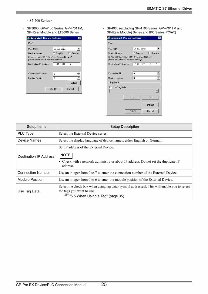
<S7-200 Series>
Setup Items Setup Description
PLC Type Select the External Device series.
Device Names Select the display language of device names, either English or German.
Destination IP Address
Set IP address of the External Device.
• Check with a network administrator about IP address. Do not set the duplicate IP address.
Connection Number Use an integer from 0 to 7 to enter the connection number of the External Device.
Module Position Use an integer from 0 to 6 to enter the module position of the External Device.
Use Tag DataSelect the check box when using tag data (symbol addresses). This will enable you to select the tags you want to use.
"5.5 When Using a Tag" (page 35)
• GP3000, GP-4100 Series, GP-4*01TM, GP-Rear Module and LT3000 Series
• GP4000 (excluding GP-4100 Series, GP-4*01TM and GP-Rear Module) Series and IPC Series(PC/AT)

SIMATIC S7 Ethernet Driver
GP-Pro EX Device/PLC Connection Manual 26
<S7-1200 Series>
Setup Items Setup Description
PLC Type Select the External Device series.
Device Names Select the display language of device names, either English or German.
Destination IP Address
Set IP address of the External Device.
• Check with a network administrator about IP address. Do not set the duplicate IP address.
Use Tag DataSelect the check box when using tag data (symbol addresses). This will enable you to select the tags you want to use.
"5.5 When Using a Tag" (page 35)
• GP3000, GP-4100 Series, GP-4*01TM, GP-Rear Module and LT3000 Series
• GP4000 (excluding GP-4100 Series, GP-4*01TM and GP-Rear Module) Series and IPC Series(PC/AT)

SIMATIC S7 Ethernet Driver
GP-Pro EX Device/PLC Connection Manual 27
<LOGO! Series>
Setup Items Setup Description
PLC Type Select the External Device series.
Device Names Select the display language of device names, either English or German.
Destination IP Address
Set IP address of the External Device.
• Check with a network administrator about IP address. Do not set the duplicate IP address.
Use Tag DataSelect the check box when using tag data (symbol addresses). This will enable you to select the tags you want to use.
"5.5 When Using a Tag" (page 35)
• GP3000, GP-4100 Series, GP-4*01TM, GP-Rear Module and LT3000 Series
• GP4000 (excluding GP-4100 Series, GP-4*01TM and GP-Rear Module) Series and IPC Series(PC/AT)

SIMATIC S7 Ethernet Driver
GP-Pro EX Device/PLC Connection Manual 28
4.2 Setup Items in Offline Mode
Communication Settings
To display the setting screen, touch [Device/PLC Settings] from [Peripheral Settings] in offline mode. Touch the
External Device you want to set from the displayed list.
• Refer to the Maintenance/Troubleshooting guide for information on how to enter offline mode or
about the operation.
Cf. Maintenance/Troubleshooting Guide "Offline Mode"
Setup Items Setup Description
Port No.
Set the FETCH port No. and WRITE port No. of the Display. Select either [Fixed] or [Auto]. When you select [Fixed], use an integer from 1024 to 65535 to enter the port No. of the Display. When you select [Auto], the port No. will be automatically assigned regardless of the entered value. When the connection type is OP Communication, the port number set to [Port No. (FETCH)] implements communication.
Timeout (s)Use an integer from 1 to 127 to enter the time (s) for which the Display waits for the response from the External Device.
RetryIn case of no response from the External Device, use an integer from 0 to 255 to enter how many times the Display retransmits the command.
Wait To Send (ms)Use an integer from 0 to 255 to enter standby time (ms) for the Display from receiving packets to transmitting next commands.

SIMATIC S7 Ethernet Driver
GP-Pro EX Device/PLC Connection Manual 29
Device Setting
To display the setting screen, touch [Device/PLC Settings] from [Peripheral Settings]. Touch the External Device
you want to set from the displayed list, and touch [Device].
Setup Items Setup Description
Device/PLC NameSelect the External Device for device setting. Device name is a title of External Device set with GP-Pro EX.(Initial value [PLC1])
PLC TYPE
Display the PLC type.
• Please make a change of the PLC type by [Device Setting] of GP-Pro EX.
DEST IP ADDR
Set IP address of the External Device.
• Check with a network administrator about IP address. Do not set the duplicate IP address.
CONNECTION TYPE
Display the connection type.
• Please make a change of the connection type by [Device Setting] of GP-Pro EX.
FETCH PORT NO.Use an integer from 1024 to 65535 to enter the FETCH port No. of the External Device. Available only if the PLC type is "S7-300/400 Series". Valid only when the connection type is [FETH/WRITE].
WRITE PORT NO.Use an integer from 1024 to 65535 to enter the WRITE port No. of the External Device. Available only if the PLC type is "S7-300/400 Series". Valid only when the connection type is [FETH/WRITE].
CPU RACK NO.Use an integer from 0 to 7 to enter the rack number that External Device is mounted to. Available only if the PLC type is "S7-300/400 Series". Valid only when the connection type is [OP Communication].

SIMATIC S7 Ethernet Driver
GP-Pro EX Device/PLC Connection Manual 30
CPU SLOT NO.Use an integer from 0 to 31 to enter the slot number that External Device is mounted to. Available only if the PLC type is "S7-300/400 Series". Valid only when the connection type is [OP Communication].
CONNECTION NO.Use an integer from 0 to 7 to enter the connection number of the External Device. Available only if the PLC type is "S7-200 Series".
MODULE POSITIONUse an integer from 0 to 6 to enter the module position of the External Device. Available only if the PLC type is "S7-200 Series".
Setup Items Setup Description

SIMATIC S7 Ethernet Driver
GP-Pro EX Device/PLC Connection Manual 31
5 Supported Device Addresses
Range of supported device address is shown in the table below. Please note that the actually supported range of
the devices varies depending on the External Device to be used. Please check the actual range in the manual of
your External Device.
5.1 S7-300/400 Series
This address can be specified as system data area.
DeviceBit Address Word Address 32
bitsRemarks
English German English German
Data Block (OP Communication)
DB00001.DBX00000.0 -DB65535.DBX65535.7
DB00001.DBW00000 -DB65535.DBW65534
Data Block (FETCH/WRITE)
DB00001.DBX00000.0 -DB00255.DBX16383.7
DB00001.DBW00000 -DB00255.DBW16382
*1
InputI00000.0 -I00127.7
E00000.0 -E00127.7
IW00000 -IW00126
EW00000 -EW00126
*1
*1 When you write the bit address, the Display reads the word address corresponding to that of the External Device first. Change only the target bit address among the word data once read, and write the word data to the External Device.Note that the correct data may not be written if you change the word address value in the ladder program while the Display reads the data of the External Device and writes it to the External Device.
OutputQ00000.0 -Q00127.7
A00000.0 -A00127.7
QW00000 -QW00126
AW00000 -AW00126
*1
Marker M00000.0 - M00255.7 MW00000 - MW00254 *1
Timer ----- T00000 - T00255 *2 *3
*2 Write disable.
*3 Data Type varies depending on the connection type. When the connection type is OP Communication, Data Type is BCD. When it is FETCH/WRITE, Data Type is binary.
Counter -----C00000 -C00255
Z00000 -Z00255
*2 *3
• Please refer to the GP-Pro EX Reference Manual for system data area.
Cf. GP-Pro EX Reference Manual "LS Area (Direct Access Method Area)"• Please refer to the precautions on manual notation for icons in the table.
Supported Devices Symbol and Terms
• Please refer to the precautions on manual notation for icons in the table.
"Manual Symbols and Terminology"
•

SIMATIC S7 Ethernet Driver
GP-Pro EX Device/PLC Connection Manual 32
5.2 S7-200 Series
This address can be specified as system data area.
DeviceBit Address Word Address 32
bitsRemarks
English German English German
Variable V00000.0 - V10239.7 VW00000 - VW10238
InputI00000.0 -I00015.7
E00000.0 -E00015.7
IW00000 -IW00014
EW00000 -EW00014
*1
*1 Writing to the addresses IW0 to IW2 is disabled, depending on the CPU type. These addresses are reserved for onboard I/O.
OutputQ00000.0 -Q00015.7
A00000.0 -A00015.7
QW00000 -QW00014
AW00000 -AW00014
*2
*2 Only when the External Device is in the EXECUTION mode, writing to the output device is enabled. When the External Device switches to the STOP mode, the output device is reset.
Marker M00000.0 - M00031.7 MW00000 - MW00030
Timer ----- T00000 - T00255 *3
*3 Write disable.
Counter -----C00000 -C00255
Z00000 -Z00255
*3
• Please refer to the GP-Pro EX Reference Manual for system data area.
Cf. GP-Pro EX Reference Manual "LS Area (Direct Access Method Area)"• Please refer to the precautions on manual notation for icons in the table.
Supported Devices Symbol and Terms
• Please refer to the precautions on manual notation for icons in the table.
"Manual Symbols and Terminology"
•

SIMATIC S7 Ethernet Driver
GP-Pro EX Device/PLC Connection Manual 33
5.3 S7-1200 Series
This address can be specified as system data area.
DeviceBit Address Word Address 32
bitsRemarks
English German English German
Data BlockDB00001.DBX00000.0 -DB65535.DBX65535.7
DB00001.DBW00000 -DB65535.DBW65534
*1
*1 When you write the bit address, the Display reads the word address corresponding to that of the External Device first. Change only the target bit address among the word data once read, and write the word data to the External Device.Note that the correct data may not be written if you change the word address value in the ladder program while the Display reads the data of the External Device and writes it to the External Device.
InputI00000.0 -I01023.7
E00000.0 -E01023.7
IW00000 -IW01022
EW00000 -EW01022
OutputQ00000.0 -Q01023.7
A00000.0 -A01023.7
QW00000 -QW01022
AW00000 -AW01022
Marker M00000.0 - M08191.7 MW00000 - MW08190
• Please refer to the GP-Pro EX Reference Manual for system data area.
Cf. GP-Pro EX Reference Manual "LS Area (Direct Access Method Area)"• Please refer to the precautions on manual notation for icons in the table.
Supported Devices Symbol and Terms
• Please refer to the precautions on manual notation for icons in the table.
"Manual Symbols and Terminology"
•
SIMATIC S7 Ethernet Driver
GP-Pro EX Device/PLC Connection Manual 34
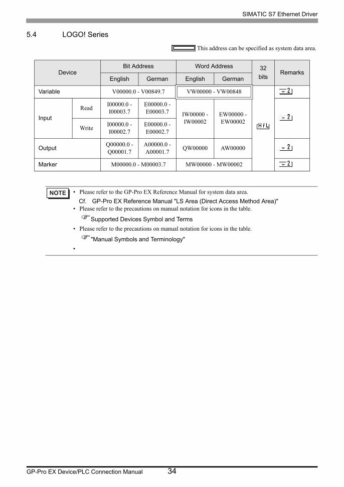
5.4 LOGO! Series
This address can be specified as system data area.
DeviceBit Address Word Address 32
bitsRemarks
English German English German
Variable V00000.0 - V00849.7 VW00000 - VW00848
Input
ReadI00000.0 -I00003.7
E00000.0 -E00003.7 IW00000 -
IW00002EW00000 -EW00002
WriteI00000.0 -I00002.7
E00000.0 -E00002.7
OutputQ00000.0 -Q00001.7
A00000.0 -A00001.7
QW00000 AW00000
Marker M00000.0 - M00003.7 MW00000 - MW00002
• Please refer to the GP-Pro EX Reference Manual for system data area.
Cf. GP-Pro EX Reference Manual "LS Area (Direct Access Method Area)"• Please refer to the precautions on manual notation for icons in the table.
Supported Devices Symbol and Terms
• Please refer to the precautions on manual notation for icons in the table.
"Manual Symbols and Terminology"
•

SIMATIC S7 Ethernet Driver
GP-Pro EX Device/PLC Connection Manual 35
5.5 When Using a Tag
S7-300/400 Series
This address can be specified as system data area.
Device Bit Address Word Address32
bitsRemarks
BOOL
Single Tag
<TAGNAME>
- - *1 *2
1D Array
<TAGNAME>[xl] - <TAGNAME>[xh]
2D Array
<TAGNAME>[xl,yl] - <TAGNAME>[xh,yh]
3D Array
<TAGNAME>[xl,yl,zl] - <TAGNAME>[xh,yh,zh]
4D Array
<TAGNAME>[xl,yl,zl,wl] - <TAGNAME>[xh,yh,zh,wh]
5D Array
<TAGNAME>[xl,yl,zl,vl,wl] - <TAGNAME>[xh,yh,zh,vh,wh]
6D Array
<TAGNAME>[xl,yl,zl,ul,vl,wl] - <TAGNAME>[xh,yh,zh,uh,vh,wh]
BYTE
Single Tag
<TAGNAME>.00 - <TAGNAME>.07
<TAGNAME>
*1 *2
1D Array
<TAGNAME>[xl].00 - <TAGNAME>[xh].07
<TAGNAME>[xl] - <TAGNAME>[xh]
2D Array
<TAGNAME>[xl,yl].00 - <TAGNAME>[xh,yh].07
<TAGNAME>[xl,yl] - <TAGNAME>[xh,yh]
3D Array
<TAGNAME>[xl,yl,zl].00 - <TAGNAME>[xh,yh,zh].07
<TAGNAME>[xl,yl,zl] - <TAGNAME>[xh,yh,zh]
4D Array
<TAGNAME>[xl,yl,zl,wl].00 - <TAGNAME>[xh,yh,zh,wh].07
<TAGNAME>[xl,yl,zl,wl] - <TAGNAME>[xh,yh,zh,wh]
5D Array
<TAGNAME>[xl,yl,zl,vl,wl].00 - <TAGNAME>[xh,yh,zh,vh,wh].07
<TAGNAME>[xl,yl,zl,vl,wl] - <TAGNAME>[xh,yh,zh,vh,wh]
6D Array
<TAGNAME>[xl,yl,zl,ul,vl,wl].00 - <TAGNAME>[xh,yh,zh,uh,vh,wh].07
<TAGNAME>[xl,yl,zl,ul,vl,wl] - <TAGNAME>[xh,yh,zh,uh,vh,wh]
SINTUSINT
Single Tag
<TAGNAME>.00 - <TAGNAME>.07
<TAGNAME> *1
SIMATIC S7 Ethernet Driver
GP-Pro EX Device/PLC Connection Manual 36
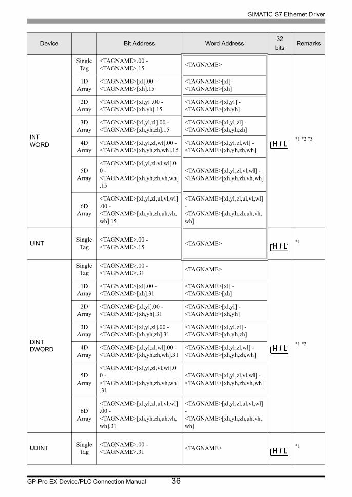
INTWORD
Single Tag
<TAGNAME>.00 - <TAGNAME>.15
<TAGNAME>
*1 *2 *3
1D Array
<TAGNAME>[xl].00 - <TAGNAME>[xh].15
<TAGNAME>[xl] - <TAGNAME>[xh]
2D Array
<TAGNAME>[xl,yl].00 - <TAGNAME>[xh,yh].15
<TAGNAME>[xl,yl] - <TAGNAME>[xh,yh]
3D Array
<TAGNAME>[xl,yl,zl].00 - <TAGNAME>[xh,yh,zh].15
<TAGNAME>[xl,yl,zl] - <TAGNAME>[xh,yh,zh]
4D Array
<TAGNAME>[xl,yl,zl,wl].00 - <TAGNAME>[xh,yh,zh,wh].15
<TAGNAME>[xl,yl,zl,wl] - <TAGNAME>[xh,yh,zh,wh]
5D Array
<TAGNAME>[xl,yl,zl,vl,wl].00 - <TAGNAME>[xh,yh,zh,vh,wh].15
<TAGNAME>[xl,yl,zl,vl,wl] - <TAGNAME>[xh,yh,zh,vh,wh]
6D Array
<TAGNAME>[xl,yl,zl,ul,vl,wl].00 - <TAGNAME>[xh,yh,zh,uh,vh,wh].15
<TAGNAME>[xl,yl,zl,ul,vl,wl] - <TAGNAME>[xh,yh,zh,uh,vh,wh]
UINTSingle
Tag<TAGNAME>.00 - <TAGNAME>.15
<TAGNAME> *1
DINTDWORD
Single Tag
<TAGNAME>.00 - <TAGNAME>.31
<TAGNAME>
*1 *2
1D Array
<TAGNAME>[xl].00 - <TAGNAME>[xh].31
<TAGNAME>[xl] - <TAGNAME>[xh]
2D Array
<TAGNAME>[xl,yl].00 - <TAGNAME>[xh,yh].31
<TAGNAME>[xl,yl] - <TAGNAME>[xh,yh]
3D Array
<TAGNAME>[xl,yl,zl].00 - <TAGNAME>[xh,yh,zh].31
<TAGNAME>[xl,yl,zl] - <TAGNAME>[xh,yh,zh]
4D Array
<TAGNAME>[xl,yl,zl,wl].00 - <TAGNAME>[xh,yh,zh,wh].31
<TAGNAME>[xl,yl,zl,wl] - <TAGNAME>[xh,yh,zh,wh]
5D Array
<TAGNAME>[xl,yl,zl,vl,wl].00 - <TAGNAME>[xh,yh,zh,vh,wh].31
<TAGNAME>[xl,yl,zl,vl,wl] - <TAGNAME>[xh,yh,zh,vh,wh]
6D Array
<TAGNAME>[xl,yl,zl,ul,vl,wl].00 - <TAGNAME>[xh,yh,zh,uh,vh,wh].31
<TAGNAME>[xl,yl,zl,ul,vl,wl] - <TAGNAME>[xh,yh,zh,uh,vh,wh]
UDINTSingle
Tag<TAGNAME>.00 - <TAGNAME>.31
<TAGNAME> *1
Device Bit Address Word Address32
bitsRemarks

SIMATIC S7 Ethernet Driver
GP-Pro EX Device/PLC Connection Manual 37
DATE*4
REALTIMETIME_OF_DAY
Single Tag
-
<TAGNAME>
*1 *2
1D Array
<TAGNAME>[xl] - <TAGNAME>[xh]
2D Array
<TAGNAME>[xl,yl] - <TAGNAME>[xh,yh]
3D Array
<TAGNAME>[xl,yl,zl] - <TAGNAME>[xh,yh,zh]
4D Array
<TAGNAME>[xl,yl,zl,wl] - <TAGNAME>[xh,yh,zh,wh]
5D Array
<TAGNAME>[xl,yl,zl,vl,wl] - <TAGNAME>[xh,yh,zh,vh,wh]
6D Array
<TAGNAME>[xl,yl,zl,ul,vl,wl] - <TAGNAME>[xh,yh,zh,uh,vh,wh]
DATE_AND_TIME
Single Tag
-
<TAGNAME>
- *1 *2 *5
1D Array
<TAGNAME>[xl] - <TAGNAME>[xh]
2D Array
<TAGNAME>[xl,yl] - <TAGNAME>[xh,yh]
3D Array
<TAGNAME>[xl,yl,zl] - <TAGNAME>[xh,yh,zh]
4D Array
<TAGNAME>[xl,yl,zl,wl] - <TAGNAME>[xh,yh,zh,wh]
5D Array
<TAGNAME>[xl,yl,zl,vl,wl] - <TAGNAME>[xh,yh,zh,vh,wh]
6D Array
<TAGNAME>[xl,yl,zl,ul,vl,wl] - <TAGNAME>[xh,yh,zh,uh,vh,wh]
Device Bit Address Word Address32
bitsRemarks

SIMATIC S7 Ethernet Driver
GP-Pro EX Device/PLC Connection Manual 38
STRING
Single Tag
-
<TAGNAME>
- *1 *2
1D Array
<TAGNAME>[xl] - <TAGNAME>[xh]
2D Array
<TAGNAME>[xl,yl] - <TAGNAME>[xh,yh]
3D Array
<TAGNAME>[xl,yl,zl] - <TAGNAME>[xh,yh,zh]
4D Array
<TAGNAME>[xl,yl,zl,wl] - <TAGNAME>[xh,yh,zh,wh]
5D Array
<TAGNAME>[xl,yl,zl,vl,wl] - <TAGNAME>[xh,yh,zh,vh,wh]
6D Array
<TAGNAME>[xl,yl,zl,ul,vl,wl] - <TAGNAME>[xh,yh,zh,uh,vh,wh]
*1 <TAGNAME>: For structures, Tag Name includes the structure name. The maximum length of the Tag Name is 255 characters, which includes delimiters and the element number.
ExampleBOOL type single tag: "BOOLSYMBOL"BOOL type 1D array: "BOOL1D[10]"WORD type 2D array: "WORD2D[10,10]"UDINT type 3D array: "UDINT[0,1,2]"User-defined structure: "STRUCT001.STRINGSYM"
*2 The number of elements for each dimension is shown from "l" (Number of minimum element) to "h" (Number of maximum element).
*3 By default, the system data area is set up with 16 words. Even if you want to use less than 16 words for the system data area, you have to map a 16 word (or larger) array tag and then select the items for the system data area.
*4 Handled as 16-bit devices in the External Device, but as 32-bit devices in GP-Pro EX.
*5 64-bit device
• To use tags, you need to import Tag Data (symbol addresses).For information about how to import, please refer to GP-Pro EX Reference Manual.Cf. GP-Pro EX Reference Manual, "Using Device/PLC Tags"
• When the tag of the "S5TIME" data type is imported, the data type is changed to "WORD". When the tag of the "CHAR" data type is imported, the data type is changed to "STRING (CHAR)".
Device Bit Address Word Address32
bitsRemarks

SIMATIC S7 Ethernet Driver
GP-Pro EX Device/PLC Connection Manual 39
• Please refer to the GP-Pro EX Reference Manual for system data area.
Cf. GP-Pro EX Reference Manual "LS Area (Direct Access Method Area)"• Please refer to the precautions on manual notation for icons in the table.
Supported Devices Symbol and Terms
• Please refer to the precautions on manual notation for icons in the table.
"Manual Symbols and Terminology"
SIMATIC S7 Ethernet Driver
GP-Pro EX Device/PLC Connection Manual 40
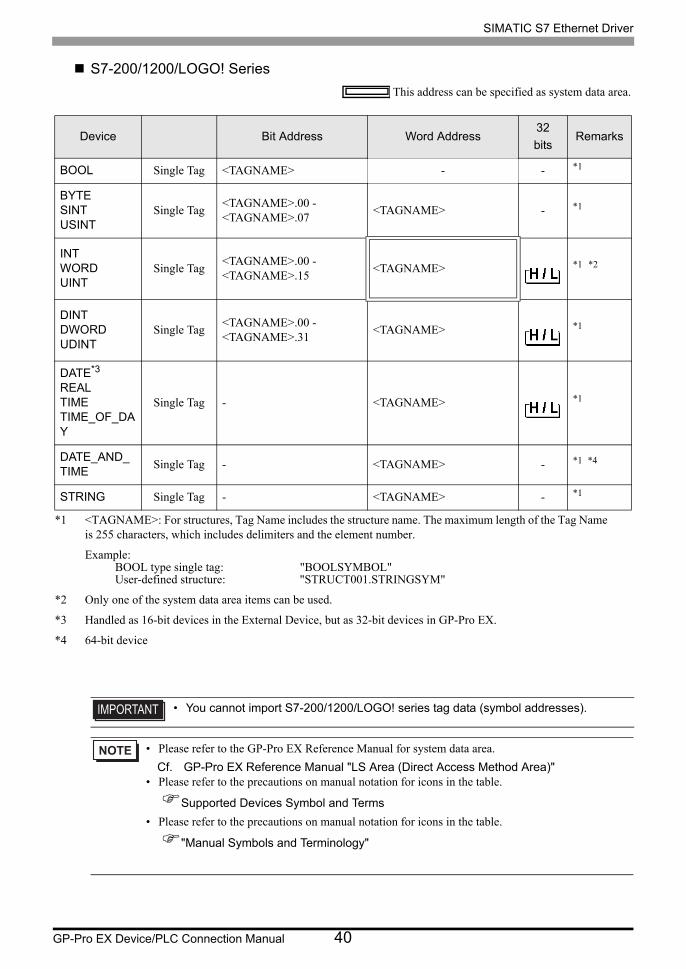
S7-200/1200/LOGO! Series
This address can be specified as system data area.
Device Bit Address Word Address32
bitsRemarks
BOOL Single Tag <TAGNAME> - - *1
*1 <TAGNAME>: For structures, Tag Name includes the structure name. The maximum length of the Tag Name is 255 characters, which includes delimiters and the element number.
Example:BOOL type single tag: "BOOLSYMBOL"User-defined structure: "STRUCT001.STRINGSYM"
BYTESINTUSINT
Single Tag<TAGNAME>.00 - <TAGNAME>.07
<TAGNAME> - *1
INTWORDUINT
Single Tag<TAGNAME>.00 - <TAGNAME>.15
<TAGNAME> *1 *2
*2 Only one of the system data area items can be used.
DINTDWORDUDINT
Single Tag<TAGNAME>.00 - <TAGNAME>.31
<TAGNAME> *1
DATE*3
REALTIMETIME_OF_DAY
*3 Handled as 16-bit devices in the External Device, but as 32-bit devices in GP-Pro EX.
Single Tag - <TAGNAME> *1
DATE_AND_TIME
Single Tag - <TAGNAME> - *1 *4
*4 64-bit device
STRING Single Tag - <TAGNAME> - *1
• You cannot import S7-200/1200/LOGO! series tag data (symbol addresses).
• Please refer to the GP-Pro EX Reference Manual for system data area.
Cf. GP-Pro EX Reference Manual "LS Area (Direct Access Method Area)"• Please refer to the precautions on manual notation for icons in the table.
Supported Devices Symbol and Terms
• Please refer to the precautions on manual notation for icons in the table.
"Manual Symbols and Terminology"

SIMATIC S7 Ethernet Driver
GP-Pro EX Device/PLC Connection Manual 41
6 Device Code and Address Code
Use device code and address code when you select "Device Type & Address" for the address type in data displays.
DeviceDevice Name Device Code
(HEX)Address Code
English German
Data Block DB DB 0000(Data Block No. x 0x10000) + Value of (word address divided by 2)
Input I E 0080Value of word address divided by 2
Output Q A 0081Value of word address divided by 2
Marker M M 0082Value of word address divided by 2
Timer T T 0060 Word Address
Counter C Z 0061 Word Address
Variable V V 0001Value of word address divided by 2

SIMATIC S7 Ethernet Driver
GP-Pro EX Device/PLC Connection Manual 42
7 Error Messages
Error messages are displayed on the Display screen as follows: "No.: Device Name: Error Message (Error
Occurrence Area)". Each description is shown below.
Display Examples of Error Messages
"RHAA035: PLC1: Error has been responded for device write command (Error Code: 2 [02H])"
Error Code Peculiar to External Device
<Connection type: FETCH/WRITE>
<Connection type: OP Communication>
Item Description
No. Error No.
Device NameName of the External Device where error occurs. Device name is a title of the External Device set with GP-Pro EX. (Initial value [PLC1])
Error Message Displays messages related to the error which occurs.
Error Occurrence Area
Displays IP address or device address of the External Device where error occurs, or error codes received from the External Device.
• IP address is displayed such as "IP address (Decimal): MAC address (Hex)".• Device address is displayed such as "Address: Device address".• Received error codes are displayed such as "Decimal [Hex]".
• Refer to your External Device manual for details on received error codes.
• Refer to "Display-related errors" in "Maintenance/Troubleshooting Guide" for details on the error
messages common to the driver.
Error Code Description Comment
0x09Address Error: Trying to access an address that does not exist.
Check the address and correct it. It may be out of the address range, or DB may not be set to the External Device.
Error Code Description Comment
0x05Trying to access an address that does not exist.
Check the address range.
0x0A Trying to access a DB that does not exist. Check that DB is set.