siemens ag: simatic s7 mpi direct · simatic s7 mpi direct driver gp-pro ex device/plc connection...
TRANSCRIPT
1
Siemens AG
SIMATIC S7 MPI Direct Driver
1 System Configuration....................................................................................................... 3
2 Selection of External Device ............................................................................................ 6
3 Example of Communication Setting ................................................................................. 7
4 Setup Items .................................................................................................................... 19
5 Cable Diagram ............................................................................................................... 26
6 Supported Device........................................................................................................... 34
7 Device Code and Address Code.................................................................................... 48
8 Error Messages.............................................................................................................. 49
SIMATIC S7 MPI Direct Driver
GP-Pro EX Device/PLC Connection Manual 2
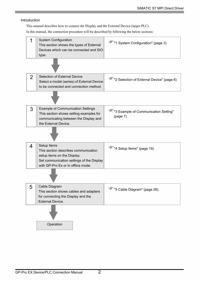
Introduction
This manual describes how to connect the Display and the External Device (target PLC).
In this manual, the connection procedure will be described by following the below sections:
1 System Configuration
This section shows the types of External
Devices which can be connected and SIO
type.
"1 System Configuration" (page 3)
2 Selection of External Device
Select a model (series) of External Device
to be connected and connection method.
"2 Selection of External Device" (page 6)
3 Example of Communication Settings
This section shows setting examples for
communicating between the Display and
the External Device.
"3 Example of Communication Setting" (page 7)
4 Setup Items
This section describes communication
setup items on the Display.
Set communication settings of the Display
with GP-Pro Ex or in offline mode.
"4 Setup Items" (page 19)
5 Cable Diagram
This section shows cables and adapters
for connecting the Display and the
External Device.
"5 Cable Diagram" (page 26)
Operation
SIMATIC S7 MPI Direct Driver
GP-Pro EX Device/PLC Connection Manual 3
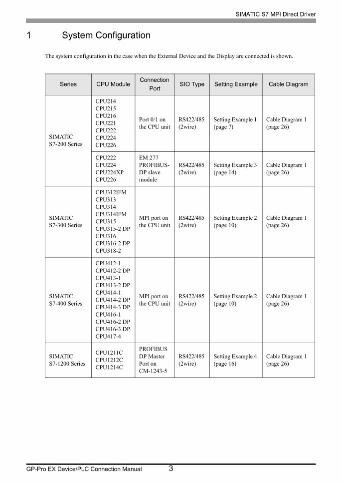
1 System Configuration
The system configuration in the case when the External Device and the Display are connected is shown.
Series CPU ModuleConnection
PortSIO Type Setting Example Cable Diagram
SIMATICS7-200 Series
CPU214CPU215CPU216CPU221CPU222CPU224CPU226
Port 0/1 on the CPU unit
RS422/485 (2wire)
Setting Example 1 (page 7)
Cable Diagram 1 (page 26)
CPU222CPU224CPU224XPCPU226
EM 277 PROFIBUS-DP slave module
RS422/485 (2wire)
Setting Example 3 (page 14)
Cable Diagram 1 (page 26)
SIMATICS7-300 Series
CPU312IFMCPU313CPU314CPU314IFMCPU315CPU315-2 DPCPU316CPU316-2 DPCPU318-2
MPI port on the CPU unit
RS422/485 (2wire)
Setting Example 2 (page 10)
Cable Diagram 1 (page 26)
SIMATICS7-400 Series
CPU412-1CPU412-2 DPCPU413-1CPU413-2 DPCPU414-1CPU414-2 DPCPU414-3 DPCPU416-1CPU416-2 DPCPU416-3 DPCPU417-4
MPI port on the CPU unit
RS422/485 (2wire)
Setting Example 2 (page 10)
Cable Diagram 1 (page 26)
SIMATICS7-1200 Series
CPU1211CCPU1212CCPU1214C
PROFIBUS DP Master Port on CM-1243-5
RS422/485 (2wire)
Setting Example 4 (page 16)
Cable Diagram 1 (page 26)
SIMATIC S7 MPI Direct Driver
GP-Pro EX Device/PLC Connection Manual 4
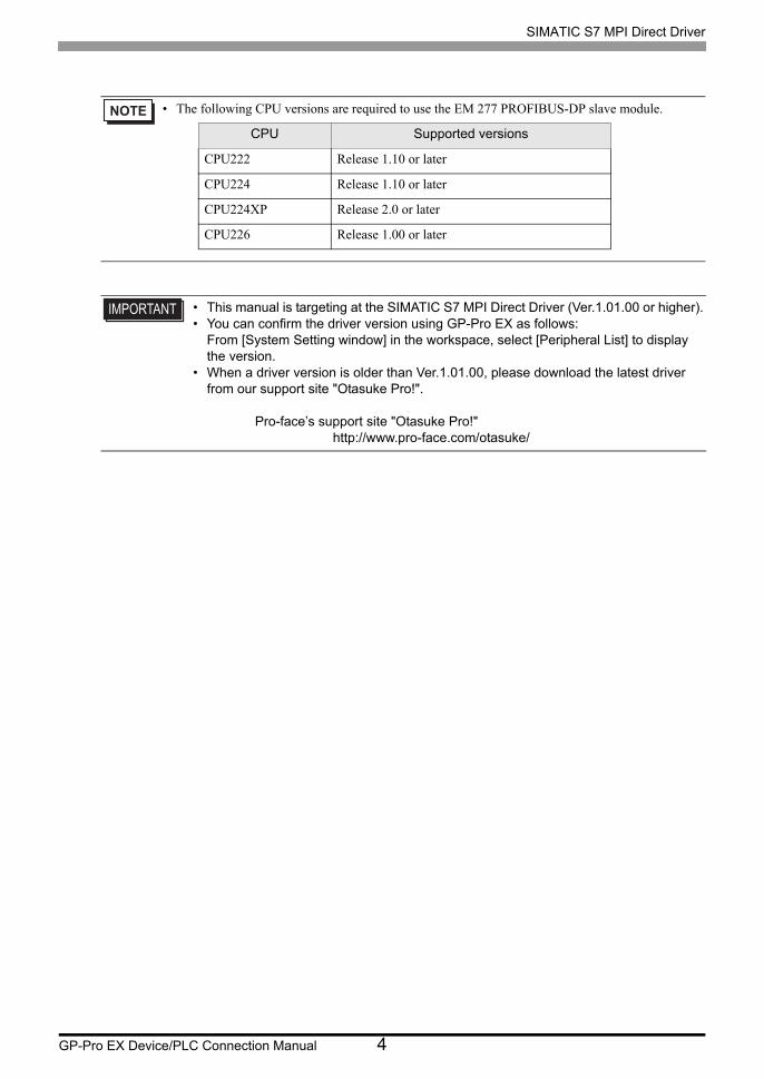
• The following CPU versions are required to use the EM 277 PROFIBUS-DP slave module.
• This manual is targeting at the SIMATIC S7 MPI Direct Driver (Ver.1.01.00 or higher).• You can confirm the driver version using GP-Pro EX as follows:
From [System Setting window] in the workspace, select [Peripheral List] to display the version.
• When a driver version is older than Ver.1.01.00, please download the latest driver from our support site "Otasuke Pro!". Pro-face’s support site "Otasuke Pro!" http://www.pro-face.com/otasuke/
CPU Supported versions
CPU222 Release 1.10 or later
CPU224 Release 1.10 or later
CPU224XP Release 2.0 or later
CPU226 Release 1.00 or later
SIMATIC S7 MPI Direct Driver
GP-Pro EX Device/PLC Connection Manual 5
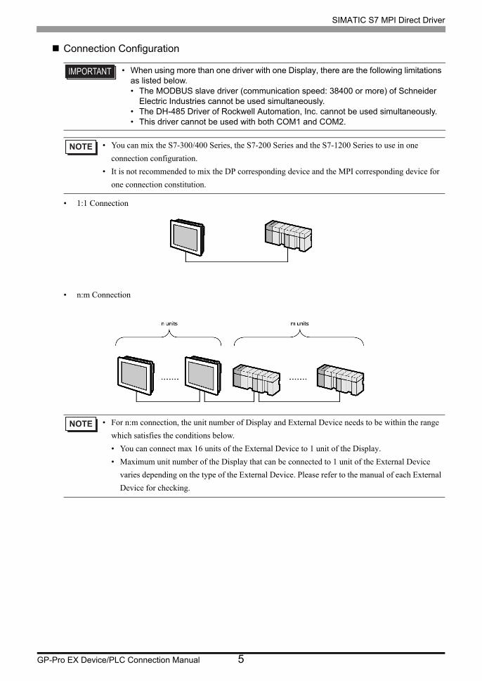
Connection Configuration
• 1:1 Connection
• n:m Connection
• When using more than one driver with one Display, there are the following limitations as listed below.• The MODBUS slave driver (communication speed: 38400 or more) of Schneider
Electric Industries cannot be used simultaneously.• The DH-485 Driver of Rockwell Automation, Inc. cannot be used simultaneously.• This driver cannot be used with both COM1 and COM2.
• You can mix the S7-300/400 Series, the S7-200 Series and the S7-1200 Series to use in one
connection configuration.
• It is not recommended to mix the DP corresponding device and the MPI corresponding device for
one connection constitution.
• For n:m connection, the unit number of Display and External Device needs to be within the range
which satisfies the conditions below.
• You can connect max 16 units of the External Device to 1 unit of the Display.
• Maximum unit number of the Display that can be connected to 1 unit of the External Device
varies depending on the type of the External Device. Please refer to the manual of each External
Device for checking.
SIMATIC S7 MPI Direct Driver
GP-Pro EX Device/PLC Connection Manual 6
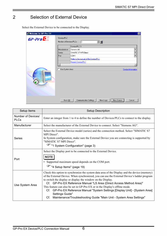
2 Selection of External Device
Select the External Device to be connected to the Display.
Setup Items Setup Description
Number of Devices/PLCs
Enter an integer from 1 to 4 to define the number of Devices/PLCs to connect to the display.
Manufacturer Select the manufacturer of the External Device to connect. Select "Siemens AG".
Series
Select the External Device model (series) and the connection method. Select "SIMATIC S7 MPI Direct".In System configuration, make sure the External Device you are connecting is supported by "SIMATIC S7 MPI Direct".
"1 System Configuration" (page 3)
Port
Select the Display port to be connected to the External Device.
• Supported maximum speed depends on the COM port.
"4 Setup Items" (page 19)
Use System Area
Check this option to synchronize the system data area of the Display and the device (memory) of the External Device. When synchronized, you can use the External Device’s ladder program to switch the display or display the window on the Display.
Cf. GP-Pro EX Reference Manual "LS Area (Direct Access Method Area)"This feature can also be set in GP-Pro EX or in the Display's offline mode.
Cf. GP-Pro EX Reference Manual "System Settings [Display Unit] - [System Area] Settings Guide"
Cf. Maintenance/Troubleshooting Guide "Main Unit - System Area Settings"
SIMATIC S7 MPI Direct Driver
GP-Pro EX Device/PLC Connection Manual 7
3 Example of Communication Setting
Examples of communication settings of the Display and the External Device, recommended by Pro-face, are
shown.
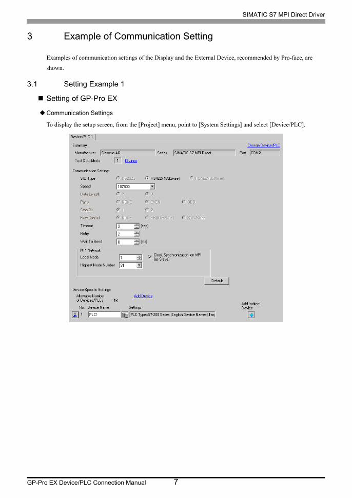
3.1 Setting Example 1
Setting of GP-Pro EX
Communication Settings
To display the setup screen, from the [Project] menu, point to [System Settings] and select [Device/PLC].
SIMATIC S7 MPI Direct Driver
GP-Pro EX Device/PLC Connection Manual 8
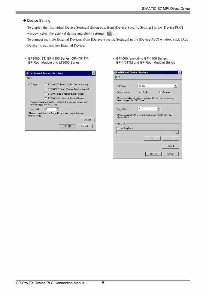
Device Setting
To display the [Individual Device Settings] dialog box, from [Device-Specific Settings] in the [Device/PLC]
window, select the external device and click [Settings] .
To connect multiple External Devices, from [Device-Specific Settings] in the [Device/PLC] window, click [Add
Device] to add another External Device.
• GP3000, ST, GP-4100 Series, GP-4*01TM, GP-Rear Module and LT3000 Series
• GP4000 (excluding GP-4100 Series, GP-4*01TM and GP-Rear Module) Series
SIMATIC S7 MPI Direct Driver
GP-Pro EX Device/PLC Connection Manual 9
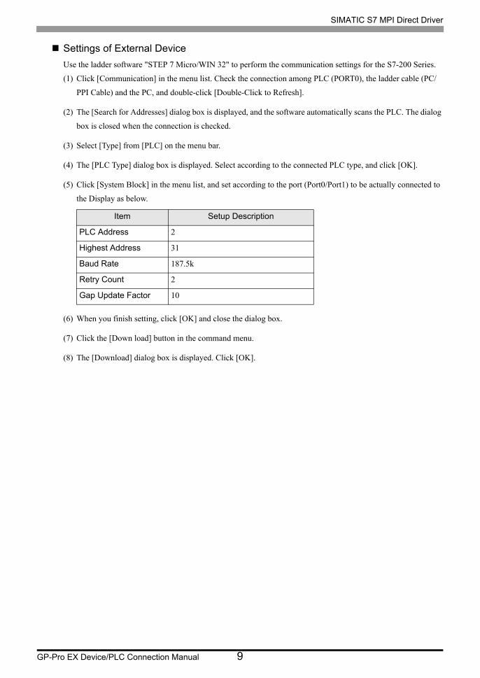
Settings of External Device
Use the ladder software "STEP 7 Micro/WIN 32" to perform the communication settings for the S7-200 Series.
(1) Click [Communication] in the menu list. Check the connection among PLC (PORT0), the ladder cable (PC/
PPI Cable) and the PC, and double-click [Double-Click to Refresh].
(2) The [Search for Addresses] dialog box is displayed, and the software automatically scans the PLC. The dialog
box is closed when the connection is checked.
(3) Select [Type] from [PLC] on the menu bar.
(4) The [PLC Type] dialog box is displayed. Select according to the connected PLC type, and click [OK].
(5) Click [System Block] in the menu list, and set according to the port (Port0/Port1) to be actually connected to
the Display as below.
(6) When you finish setting, click [OK] and close the dialog box.
(7) Click the [Down load] button in the command menu.
(8) The [Download] dialog box is displayed. Click [OK].
Item Setup Description
PLC Address 2
Highest Address 31
Baud Rate 187.5k
Retry Count 2
Gap Update Factor 10

SIMATIC S7 MPI Direct Driver
GP-Pro EX Device/PLC Connection Manual 10
3.2 Setting Example 2
Setting of GP-Pro EX
Communication Settings
To display the setup screen, from the [Project] menu, point to [System Settings] and select [Device/PLC].
SIMATIC S7 MPI Direct Driver
GP-Pro EX Device/PLC Connection Manual 11
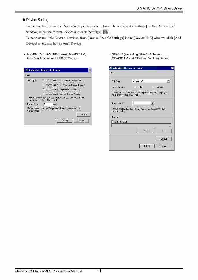
Device Setting
To display the [Individual Device Settings] dialog box, from [Device-Specific Settings] in the [Device/PLC]
window, select the external device and click [Settings] .
To connect multiple External Devices, from [Device-Specific Settings] in the [Device/PLC] window, click [Add
Device] to add another External Device.
• GP3000, ST, GP-4100 Series, GP-4*01TM, GP-Rear Module and LT3000 Series
• GP4000 (excluding GP-4100 Series, GP-4*01TM and GP-Rear Module) Series
SIMATIC S7 MPI Direct Driver
GP-Pro EX Device/PLC Connection Manual 12
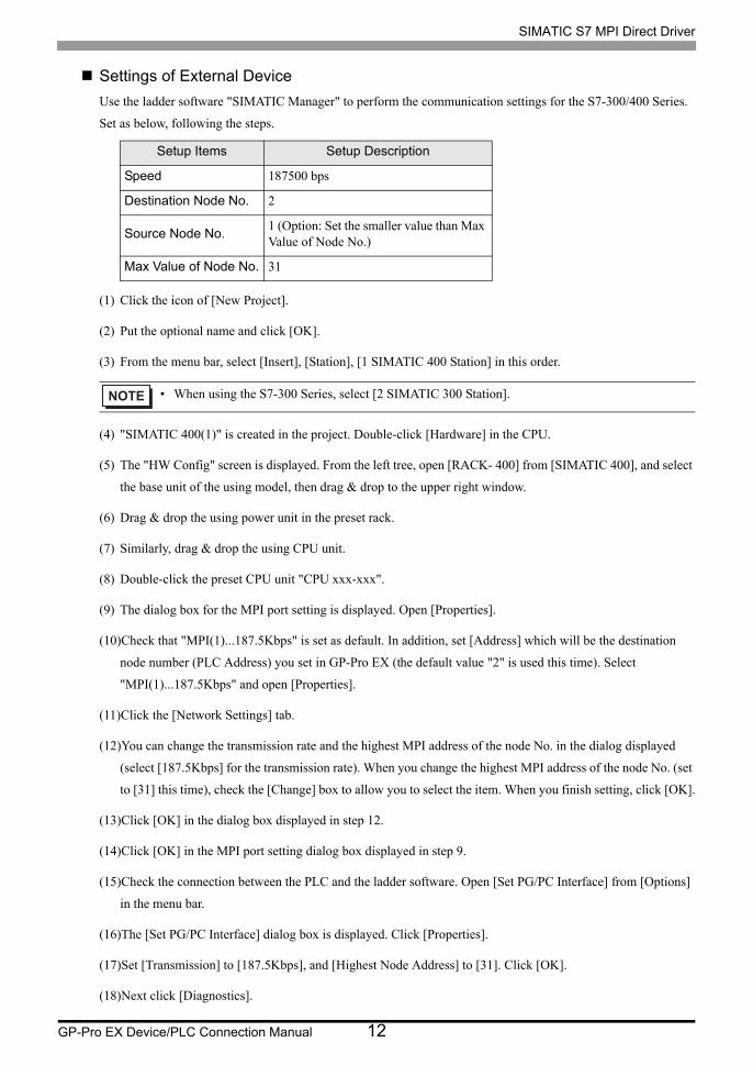
Settings of External Device
Use the ladder software "SIMATIC Manager" to perform the communication settings for the S7-300/400 Series.
Set as below, following the steps.
(1) Click the icon of [New Project].
(2) Put the optional name and click [OK].
(3) From the menu bar, select [Insert], [Station], [1 SIMATIC 400 Station] in this order.
(4) "SIMATIC 400(1)" is created in the project. Double-click [Hardware] in the CPU.
(5) The "HW Config" screen is displayed. From the left tree, open [RACK- 400] from [SIMATIC 400], and select
the base unit of the using model, then drag & drop to the upper right window.
(6) Drag & drop the using power unit in the preset rack.
(7) Similarly, drag & drop the using CPU unit.
(8) Double-click the preset CPU unit "CPU xxx-xxx".
(9) The dialog box for the MPI port setting is displayed. Open [Properties].
(10)Check that "MPI(1)...187.5Kbps" is set as default. In addition, set [Address] which will be the destination
node number (PLC Address) you set in GP-Pro EX (the default value "2" is used this time). Select
"MPI(1)...187.5Kbps" and open [Properties].
(11)Click the [Network Settings] tab.
(12)You can change the transmission rate and the highest MPI address of the node No. in the dialog displayed
(select [187.5Kbps] for the transmission rate). When you change the highest MPI address of the node No. (set
to [31] this time), check the [Change] box to allow you to select the item. When you finish setting, click [OK].
(13)Click [OK] in the dialog box displayed in step 12.
(14)Click [OK] in the MPI port setting dialog box displayed in step 9.
(15)Check the connection between the PLC and the ladder software. Open [Set PG/PC Interface] from [Options]
in the menu bar.
(16)The [Set PG/PC Interface] dialog box is displayed. Click [Properties].
(17)Set [Transmission] to [187.5Kbps], and [Highest Node Address] to [31]. Click [OK].
(18)Next click [Diagnostics].
Setup Items Setup Description
Speed 187500 bps
Destination Node No. 2
Source Node No.1 (Option: Set the smaller value than Max Value of Node No.)
Max Value of Node No. 31
• When using the S7-300 Series, select [2 SIMATIC 300 Station].
SIMATIC S7 MPI Direct Driver
GP-Pro EX Device/PLC Connection Manual 13
(19)Click [Test] and [Read].
(20)If "OK" is displayed and other items than [0-0] of [Bus Nodes] are checked, the connection with the PLC is
established. Click [OK] and close the dialog box.
(21)Open "Configure Network". Select the using CPU unit and click the [Download] button.
(22)When the "PLC Download Selected Stations" is displayed, click "Yes" and continue to download.
(23)When you finish downloading, the dialog box is closed.
(24)Close the [Configure Network] window. When the [Network Save and Compile] dialog box is displayed,
click [Yes].
(25)When the [Save and Compile] dialog box is displayed, click [OK].
PLC setting is completed at above.
SIMATIC S7 MPI Direct Driver
GP-Pro EX Device/PLC Connection Manual 14
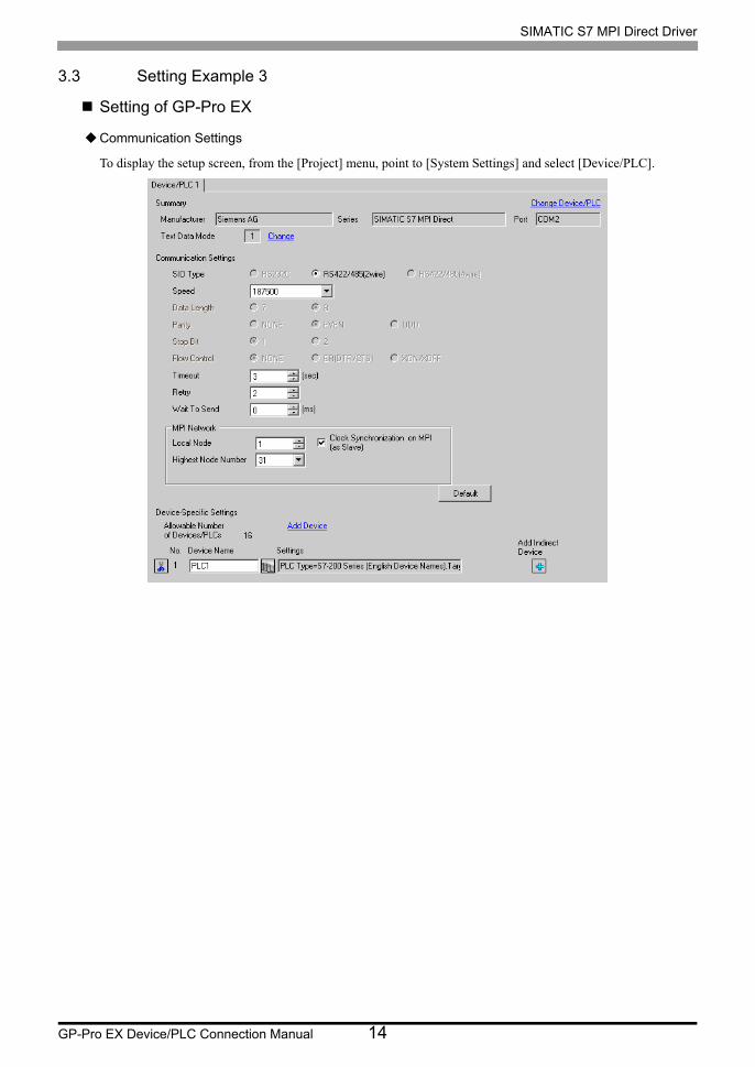
3.3 Setting Example 3
Setting of GP-Pro EX
Communication Settings
To display the setup screen, from the [Project] menu, point to [System Settings] and select [Device/PLC].
SIMATIC S7 MPI Direct Driver
GP-Pro EX Device/PLC Connection Manual 15
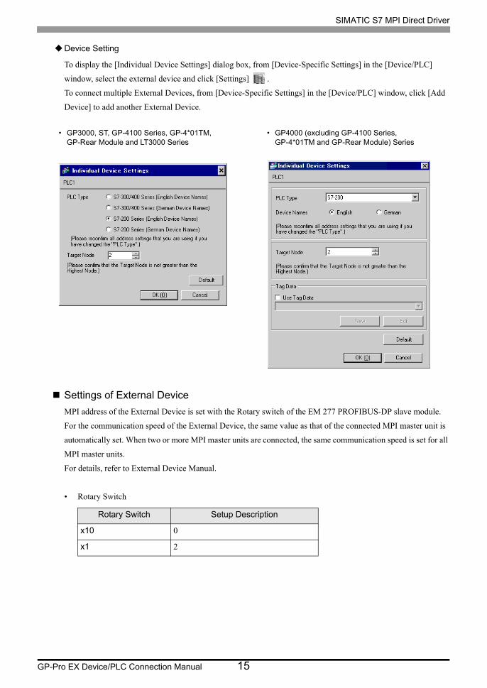
Device Setting
To display the [Individual Device Settings] dialog box, from [Device-Specific Settings] in the [Device/PLC]
window, select the external device and click [Settings] .
To connect multiple External Devices, from [Device-Specific Settings] in the [Device/PLC] window, click [Add
Device] to add another External Device.
Settings of External Device
MPI address of the External Device is set with the Rotary switch of the EM 277 PROFIBUS-DP slave module.
For the communication speed of the External Device, the same value as that of the connected MPI master unit is
automatically set. When two or more MPI master units are connected, the same communication speed is set for all
MPI master units.
For details, refer to External Device Manual.
• Rotary Switch
Rotary Switch Setup Description
x10 0
x1 2
• GP3000, ST, GP-4100 Series, GP-4*01TM, GP-Rear Module and LT3000 Series
• GP4000 (excluding GP-4100 Series, GP-4*01TM and GP-Rear Module) Series
SIMATIC S7 MPI Direct Driver
GP-Pro EX Device/PLC Connection Manual 16
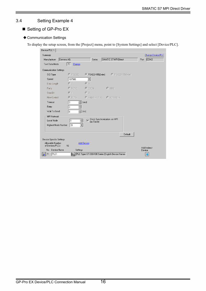
3.4 Setting Example 4
Setting of GP-Pro EX
Communication Settings
To display the setup screen, from the [Project] menu, point to [System Settings] and select [Device/PLC].

SIMATIC S7 MPI Direct Driver
GP-Pro EX Device/PLC Connection Manual 17
Device Setting
To display the [Individual Device Settings] dialog box, from [Device-Specific Settings] in the [Device/PLC]
window, select the external device and click [Settings] .
To connect multiple External Devices, from [Device-Specific Settings] in the [Device/PLC] window, click [Add
Device] to add another External Device.
Note
• If you are using a S7-1200 Series device, from the [PLC Type] list select [S7-300/400].
• GP3000, ST, GP-4100 Series, GP-4*01TM, GP-Rear Module and LT3000 Series
• GP4000 (excluding GP-4100 Series, GP-4*01TM and GP-Rear Module) Series
SIMATIC S7 MPI Direct Driver
GP-Pro EX Device/PLC Connection Manual 18
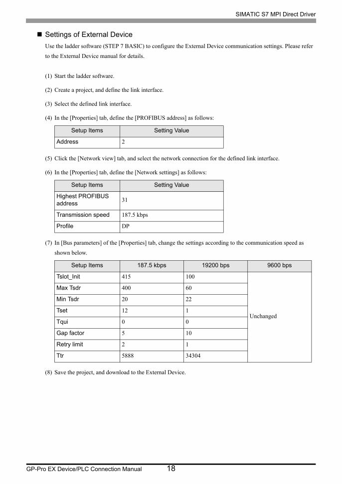
Settings of External Device
Use the ladder software (STEP 7 BASIC) to configure the External Device communication settings. Please refer
to the External Device manual for details.
(1) Start the ladder software.
(2) Create a project, and define the link interface.
(3) Select the defined link interface.
(4) In the [Properties] tab, define the [PROFIBUS address] as follows:
(5) Click the [Network view] tab, and select the network connection for the defined link interface.
(6) In the [Properties] tab, define the [Network settings] as follows:
(7) In [Bus parameters] of the [Properties] tab, change the settings according to the communication speed as
shown below.
(8) Save the project, and download to the External Device.
Setup Items Setting Value
Address 2
Setup Items Setting Value
Highest PROFIBUS address
31
Transmission speed 187.5 kbps
Profile DP
Setup Items 187.5 kbps 19200 bps 9600 bps
Tslot_Init 415 100
Unchanged
Max Tsdr 400 60
Min Tsdr 20 22
Tset 12 1
Tqui 0 0
Gap factor 5 10
Retry limit 2 1
Ttr 5888 34304
SIMATIC S7 MPI Direct Driver
GP-Pro EX Device/PLC Connection Manual 19
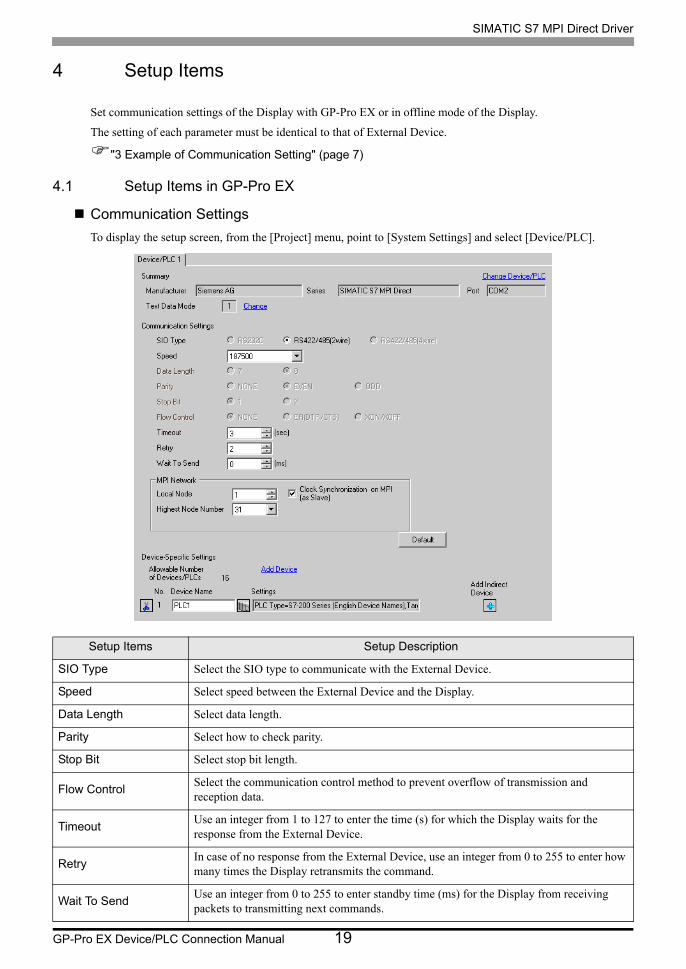
4 Setup Items
Set communication settings of the Display with GP-Pro EX or in offline mode of the Display.
The setting of each parameter must be identical to that of External Device.
"3 Example of Communication Setting" (page 7)
4.1 Setup Items in GP-Pro EX
Communication Settings
To display the setup screen, from the [Project] menu, point to [System Settings] and select [Device/PLC].
Setup Items Setup Description
SIO Type Select the SIO type to communicate with the External Device.
Speed Select speed between the External Device and the Display.
Data Length Select data length.
Parity Select how to check parity.
Stop Bit Select stop bit length.
Flow ControlSelect the communication control method to prevent overflow of transmission and reception data.
TimeoutUse an integer from 1 to 127 to enter the time (s) for which the Display waits for the response from the External Device.
RetryIn case of no response from the External Device, use an integer from 0 to 255 to enter how many times the Display retransmits the command.
Wait To SendUse an integer from 0 to 255 to enter standby time (ms) for the Display from receiving packets to transmitting next commands.
SIMATIC S7 MPI Direct Driver
GP-Pro EX Device/PLC Connection Manual 20
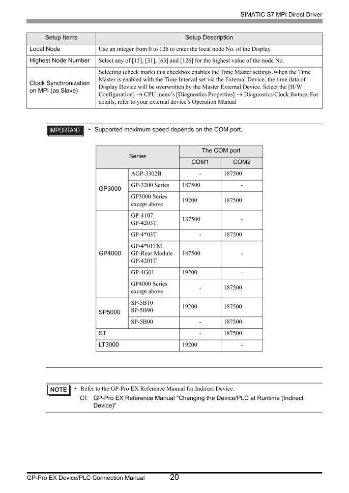
Local Node Use an integer from 0 to 126 to enter the local node No. of the Display.
Highest Node Number Select any of [15], [31], [63] and [126] for the highest value of the node No.
Clock Synchronization on MPI (as Slave)
Selecting (check mark) this checkbox enables the Time Master settings.When the Time Master is enabled with the Time Interval set via the External Device, the time data of Display Device will be overwritten by the Master External Device. Select the [H/W Configuration] CPU menu’s [Diagnostics Properties] Diagnostics/Clock feature. For details, refer to your external device’s Operation Manual
• Supported maximum speed depends on the COM port.
• Refer to the GP-Pro EX Reference Manual for Indirect Device.
Cf. GP-Pro EX Reference Manual "Changing the Device/PLC at Runtime (Indirect Device)"
Setup Items Setup Description
SeriesThe COM port
COM1 COM2
GP3000
AGP-3302B - 187500
GP-3200 Series 187500 -
GP3000 Series except above
19200 187500
GP4000
GP-4107GP-4203T
187500 -
GP-4*03T - 187500
GP-4*01TMGP-Rear ModuleGP-4201T
187500 -
GP-4G01 19200 -
GP4000 Series except above
- 187500
SP5000
SP-5B10SP-5B90
19200 187500
SP-5B00 - 187500
ST - 187500
LT3000 19200 -
SIMATIC S7 MPI Direct Driver
GP-Pro EX Device/PLC Connection Manual 21
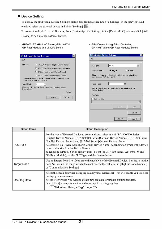
Device Setting
To display the [Individual Device Settings] dialog box, from [Device-Specific Settings] in the [Device/PLC]
window, select the external device and click [Settings] .
To connect multiple External Devices, from [Device-Specific Settings] in the [Device/PLC] window, click [Add
Device] to add another External Device.
Setup Items Setup Description
PLC Type
For the type of External Device to communicate, select any of [S-7-300/400 Series [English Device Names]], [S-7-300/400 Series [German Device Names]], [S-7-200 Series [English Device Names]] and [S-7-200 Series [German Device Names]].Select [English Device Name] or [German Device Name] depending on whether the device name is described in English or German.When using GP4000 Series display units (except for GP-4100 Series, GP-4*01TM and GP-Rear Module), set the PLC Type and the Device Name.
Target NodeUse an integer from 0 to 126 to enter the node No. of the External Device. Be sure to set the node No. within the range which does not exceed the value set in [Highest Node Number] of [Communication Settings].
Use Tag Data
Select the check box when using tag data (symbol addresses). This will enable you to select the tags you want to use.Select [New] when you want to create new tag data, or update existing tag data.Select [Edit] when you want to add new tags to existing tag data.
"6.4 When Using a Tag" (page 37)
• GP3000, ST, GP-4100 Series, GP-4*01TM, GP-Rear Module and LT3000 Series
• GP4000 (excluding GP-4100 Series, GP-4*01TM and GP-Rear Module) Series
SIMATIC S7 MPI Direct Driver
GP-Pro EX Device/PLC Connection Manual 22
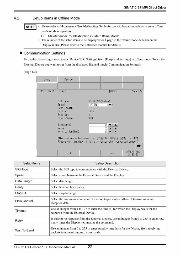
4.2 Setup Items in Offline Mode
Communication Settings
To display the setting screen, touch [Device/PLC Settings] from [Peripheral Settings] in offline mode. Touch the
External Device you want to set from the displayed list, and touch [Communication Settings].
(Page 1/2)
• Please refer to Maintenance/Troubleshooting Guide for more information on how to enter offline
mode or about operation.
Cf. Maintenance/Troubleshooting Guide "Offline Mode"• The number of the setup items to be displayed for 1 page in the offline mode depends on the
Display in use. Please refer to the Reference manual for details.
Setup Items Setup Description
SIO Type Select the SIO type to communicate with the External Device.
Speed Select speed between the External Device and the Display.
Data Length Select data length.
Parity Select how to check parity.
Stop Bit Select stop bit length.
Flow ControlSelect the communication control method to prevent overflow of transmission and reception data.
TimeoutUse an integer from 1 to 127 to enter the time (s) for which the Display waits for the response from the External Device.
RetryIn case of no response from the External Device, use an integer from 0 to 255 to enter how many times the Display retransmits the command.
Wait To SendUse an integer from 0 to 255 to enter standby time (ms) for the Display from receiving packets to transmitting next commands.
SIMATIC S7 MPI Direct Driver
GP-Pro EX Device/PLC Connection Manual 23
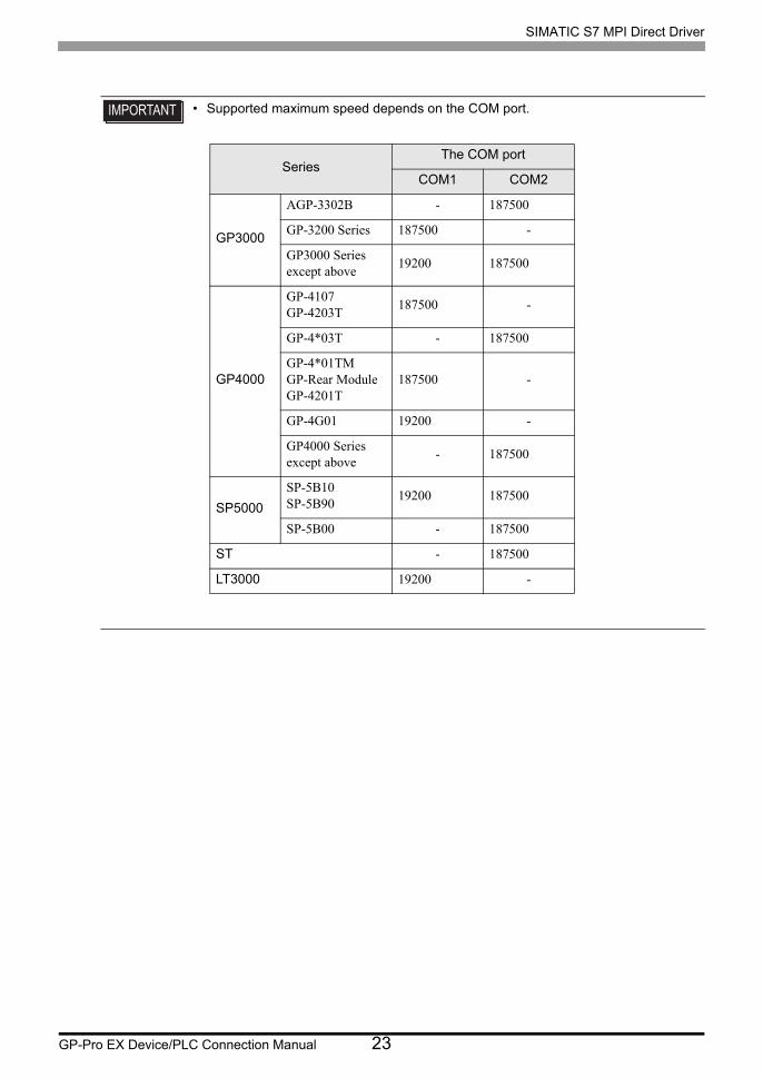
• Supported maximum speed depends on the COM port.
SeriesThe COM port
COM1 COM2
GP3000
AGP-3302B - 187500
GP-3200 Series 187500 -
GP3000 Series except above
19200 187500
GP4000
GP-4107GP-4203T
187500 -
GP-4*03T - 187500
GP-4*01TMGP-Rear ModuleGP-4201T
187500 -
GP-4G01 19200 -
GP4000 Series except above
- 187500
SP5000
SP-5B10SP-5B90
19200 187500
SP-5B00 - 187500
ST - 187500
LT3000 19200 -
SIMATIC S7 MPI Direct Driver
GP-Pro EX Device/PLC Connection Manual 24
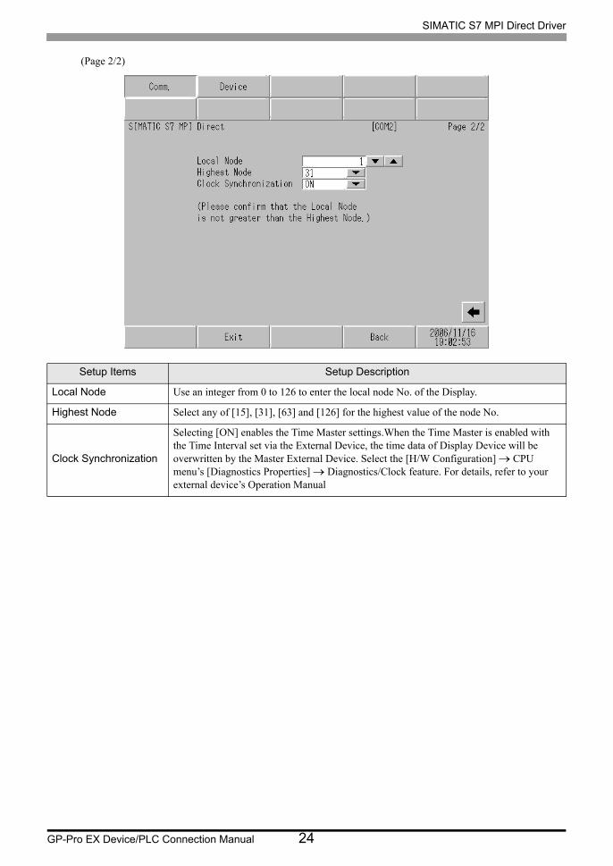
(Page 2/2)
Setup Items Setup Description
Local Node Use an integer from 0 to 126 to enter the local node No. of the Display.
Highest Node Select any of [15], [31], [63] and [126] for the highest value of the node No.
Clock Synchronization
Selecting [ON] enables the Time Master settings.When the Time Master is enabled with the Time Interval set via the External Device, the time data of Display Device will be overwritten by the Master External Device. Select the [H/W Configuration] CPU menu’s [Diagnostics Properties] Diagnostics/Clock feature. For details, refer to your external device’s Operation Manual
SIMATIC S7 MPI Direct Driver
GP-Pro EX Device/PLC Connection Manual 25
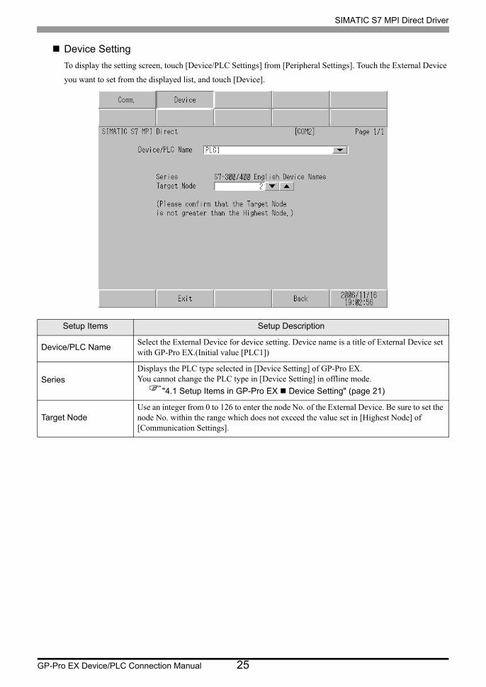
Device Setting
To display the setting screen, touch [Device/PLC Settings] from [Peripheral Settings]. Touch the External Device
you want to set from the displayed list, and touch [Device].
Setup Items Setup Description
Device/PLC NameSelect the External Device for device setting. Device name is a title of External Device set with GP-Pro EX.(Initial value [PLC1])
SeriesDisplays the PLC type selected in [Device Setting] of GP-Pro EX.You cannot change the PLC type in [Device Setting] in offline mode.
"4.1 Setup Items in GP-Pro EX Device Setting" (page 21)
Target NodeUse an integer from 0 to 126 to enter the node No. of the External Device. Be sure to set the node No. within the range which does not exceed the value set in [Highest Node] of [Communication Settings].
SIMATIC S7 MPI Direct Driver
GP-Pro EX Device/PLC Connection Manual 26
5 Cable Diagram
The following cable diagrams may be different from cable diagrams recommended by External Device
Manufacturer.
Please be assured there is no operational problem in applying the cable diagram shown in this manual.
• The FG pin of the External Device body must be grounded according to your country’s applicable standard.
Refer to your External Device manual for details.
• SG and FG are connected inside the Display. When connecting the External Device to SG, design your system
to avoid short-circuit loops.
• Connect an isolation unit if the communication is not stable due to noise or other factors.
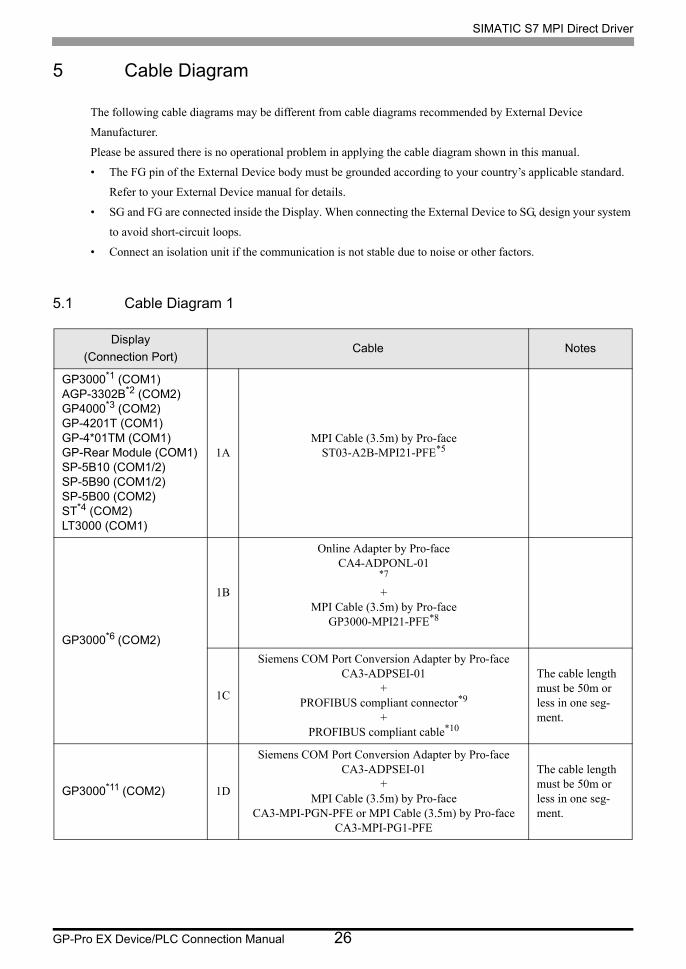
5.1 Cable Diagram 1
Display
(Connection Port)Cable Notes
GP3000*1 (COM1)AGP-3302B*2 (COM2)GP4000*3 (COM2)GP-4201T (COM1)GP-4*01TM (COM1)GP-Rear Module (COM1)SP-5B10 (COM1/2)SP-5B90 (COM1/2)SP-5B00 (COM2)ST*4 (COM2)LT3000 (COM1)
1AMPI Cable (3.5m) by Pro-face
ST03-A2B-MPI21-PFE*5
GP3000*6 (COM2)
1B
Online Adapter by Pro-faceCA4-ADPONL-01
*7
+MPI Cable (3.5m) by Pro-face
GP3000-MPI21-PFE*8
1C
Siemens COM Port Conversion Adapter by Pro-faceCA3-ADPSEI-01
+PROFIBUS compliant connector*9
+PROFIBUS compliant cable*10
The cable length must be 50m or less in one seg-ment.
GP3000*11 (COM2) 1D
Siemens COM Port Conversion Adapter by Pro-faceCA3-ADPSEI-01
+MPI Cable (3.5m) by Pro-face
CA3-MPI-PGN-PFE or MPI Cable (3.5m) by Pro-faceCA3-MPI-PG1-PFE
The cable length must be 50m or less in one seg-ment.
SIMATIC S7 MPI Direct Driver
GP-Pro EX Device/PLC Connection Manual 27
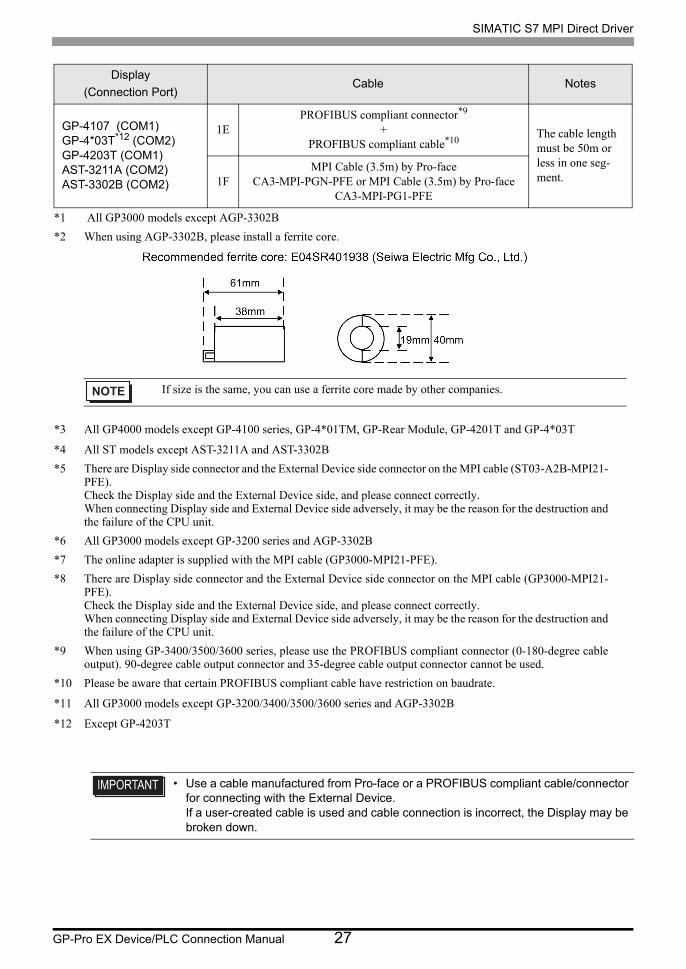
GP-4107 (COM1)GP-4*03T*12 (COM2)GP-4203T (COM1)AST-3211A (COM2)AST-3302B (COM2)
1EPROFIBUS compliant connector*9
+PROFIBUS compliant cable*10
The cable length must be 50m or less in one seg-ment.1F
MPI Cable (3.5m) by Pro-faceCA3-MPI-PGN-PFE or MPI Cable (3.5m) by Pro-face
CA3-MPI-PG1-PFE
*1 All GP3000 models except AGP-3302B
*2 When using AGP-3302B, please install a ferrite core.
*3 All GP4000 models except GP-4100 series, GP-4*01TM, GP-Rear Module, GP-4201T and GP-4*03T
*4 All ST models except AST-3211A and AST-3302B
*5 There are Display side connector and the External Device side connector on the MPI cable (ST03-A2B-MPI21- PFE).Check the Display side and the External Device side, and please connect correctly.When connecting Display side and External Device side adversely, it may be the reason for the destruction and the failure of the CPU unit.
*6 All GP3000 models except GP-3200 series and AGP-3302B
*7 The online adapter is supplied with the MPI cable (GP3000-MPI21-PFE).
*8 There are Display side connector and the External Device side connector on the MPI cable (GP3000-MPI21- PFE).Check the Display side and the External Device side, and please connect correctly.When connecting Display side and External Device side adversely, it may be the reason for the destruction and the failure of the CPU unit.
*9 When using GP-3400/3500/3600 series, please use the PROFIBUS compliant connector (0-180-degree cable output). 90-degree cable output connector and 35-degree cable output connector cannot be used.
*10 Please be aware that certain PROFIBUS compliant cable have restriction on baudrate.
*11 All GP3000 models except GP-3200/3400/3500/3600 series and AGP-3302B
*12 Except GP-4203T
• Use a cable manufactured from Pro-face or a PROFIBUS compliant cable/connector for connecting with the External Device.If a user-created cable is used and cable connection is incorrect, the Display may be broken down.
Display
(Connection Port)Cable Notes
If size is the same, you can use a ferrite core made by other companies.
SIMATIC S7 MPI Direct Driver
GP-Pro EX Device/PLC Connection Manual 28
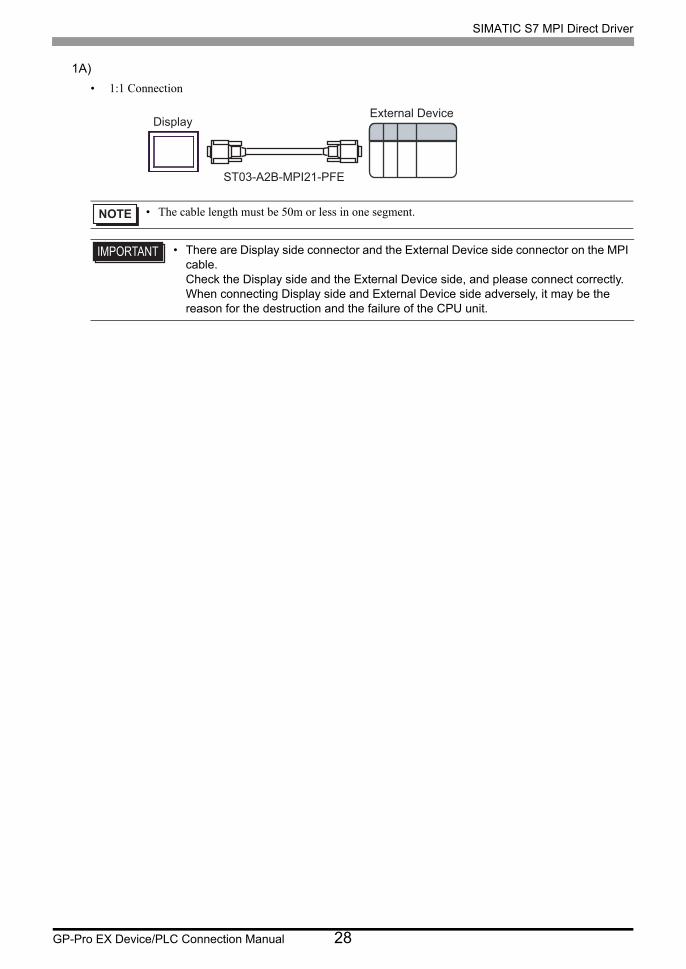
1A)
• 1:1 Connection
• The cable length must be 50m or less in one segment.
• There are Display side connector and the External Device side connector on the MPI cable.Check the Display side and the External Device side, and please connect correctly.When connecting Display side and External Device side adversely, it may be the reason for the destruction and the failure of the CPU unit.
DisplayExternal Device
ST03-A2B-MPI21-PFE
SIMATIC S7 MPI Direct Driver
GP-Pro EX Device/PLC Connection Manual 29
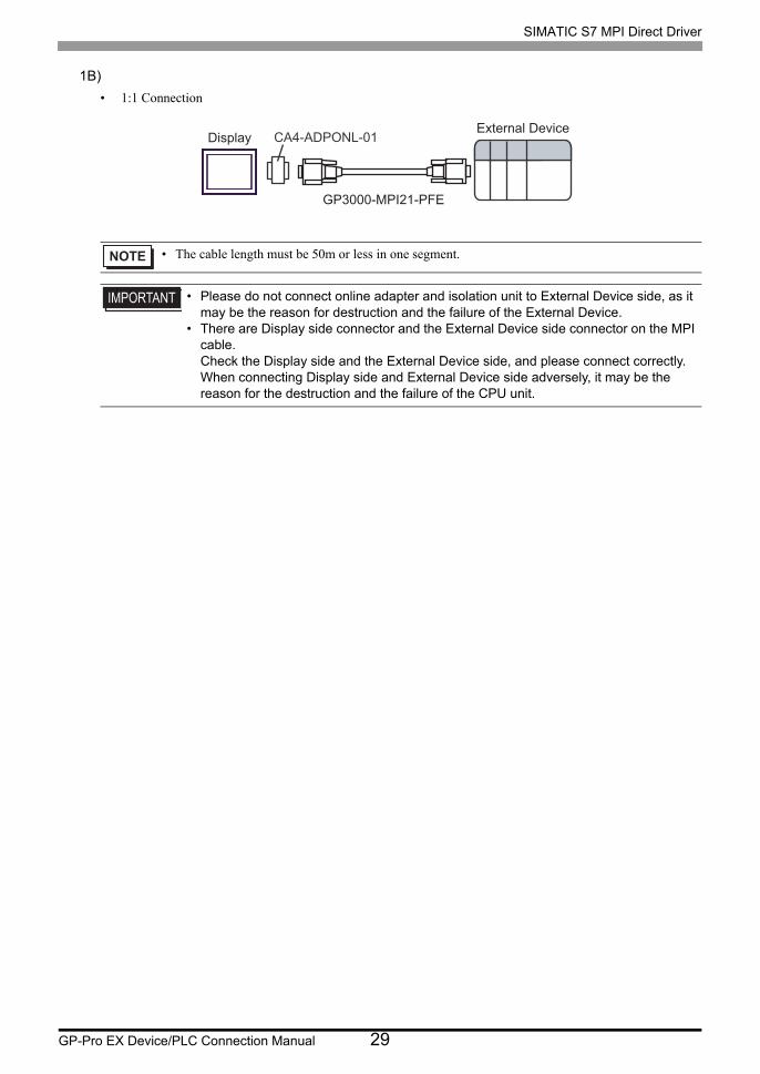
1B)
• 1:1 Connection
• The cable length must be 50m or less in one segment.
• Please do not connect online adapter and isolation unit to External Device side, as it may be the reason for destruction and the failure of the External Device.
• There are Display side connector and the External Device side connector on the MPI cable.Check the Display side and the External Device side, and please connect correctly.When connecting Display side and External Device side adversely, it may be the reason for the destruction and the failure of the CPU unit.
GP3000-MPI21-PFE
CA4-ADPONL-01DisplayExternal Device
SIMATIC S7 MPI Direct Driver
GP-Pro EX Device/PLC Connection Manual 30
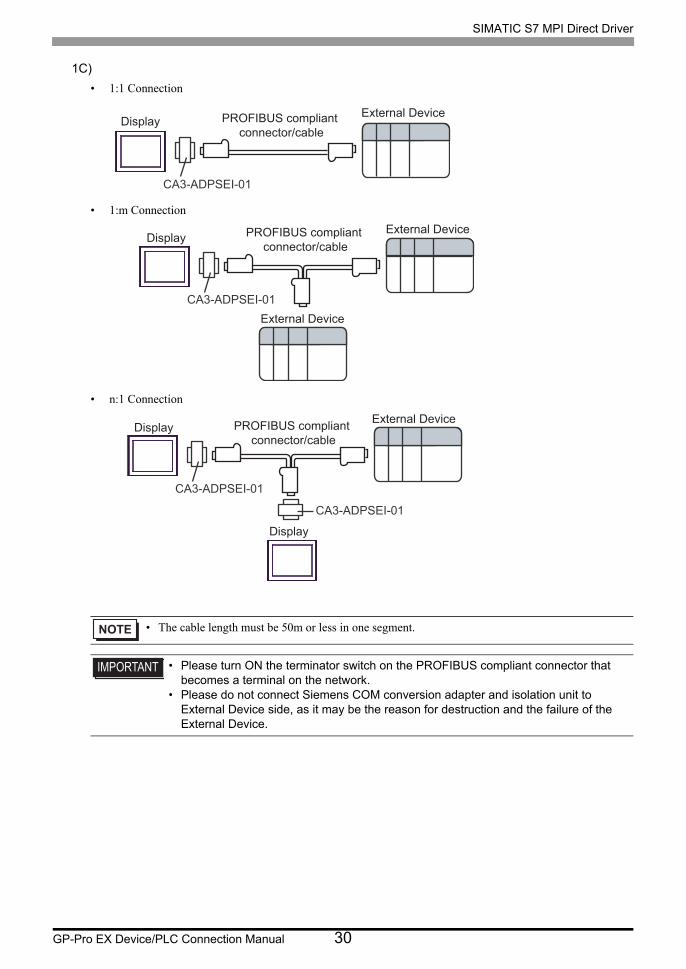
1C)
• 1:1 Connection
• 1:m Connection
• n:1 Connection
• The cable length must be 50m or less in one segment.
• Please turn ON the terminator switch on the PROFIBUS compliant connector that becomes a terminal on the network.
• Please do not connect Siemens COM conversion adapter and isolation unit to External Device side, as it may be the reason for destruction and the failure of the External Device.
PROFIBUS compliant connector/cable
CA3-ADPSEI-01
DisplayExternal Device
CA3-ADPSEI-01
DisplayExternal Device
External Device
PROFIBUS compliant connector/cable
CA3-ADPSEI-01
CA3-ADPSEI-01
Display
Display
External DevicePROFIBUS compliant connector/cable
SIMATIC S7 MPI Direct Driver
GP-Pro EX Device/PLC Connection Manual 31
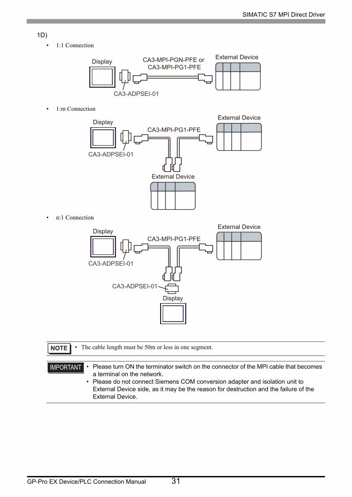
1D)
• 1:1 Connection
• 1:m Connection
• n:1 Connection
• The cable length must be 50m or less in one segment.
• Please turn ON the terminator switch on the connector of the MPI cable that becomes a terminal on the network.
• Please do not connect Siemens COM conversion adapter and isolation unit to External Device side, as it may be the reason for destruction and the failure of the External Device.
CA3-MPI-PGN-PFE or CA3-MPI-PG1-PFE
CA3-ADPSEI-01
DisplayExternal Device
CA3-MPI-PG1-PFE
CA3-ADPSEI-01
DisplayExternal Device
External Device
CA3-MPI-PG1-PFE
CA3-ADPSEI-01
CA3-ADPSEI-01
Display
Display
External Device
SIMATIC S7 MPI Direct Driver
GP-Pro EX Device/PLC Connection Manual 32
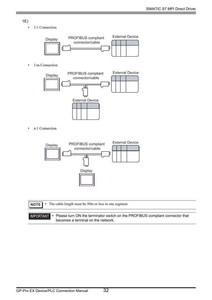
1E)
• 1:1 Connection
• 1:m Connection
• n:1 Connection
• The cable length must be 50m or less in one segment.
• Please turn ON the terminator switch on the PROFIBUS compliant connector that becomes a terminal on the network.
DisplayExternal DevicePROFIBUS compliant
connector/cable
DisplayExternal Device
External Device
PROFIBUS compliant connector/cable
Display
Display
External DevicePROFIBUS compliant connector/cable
SIMATIC S7 MPI Direct Driver
GP-Pro EX Device/PLC Connection Manual 33
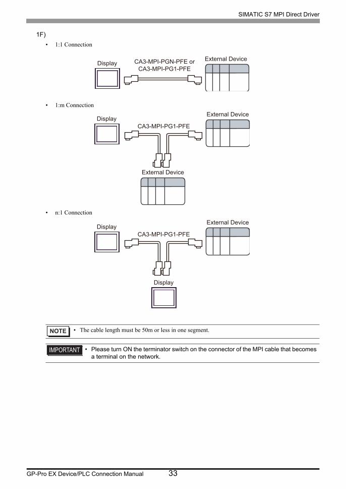
1F)
• 1:1 Connection
• 1:m Connection
• n:1 Connection
• The cable length must be 50m or less in one segment.
• Please turn ON the terminator switch on the connector of the MPI cable that becomes a terminal on the network.
CA3-MPI-PGN-PFE orCA3-MPI-PG1-PFE
DisplayExternal Device
CA3-MPI-PG1-PFEDisplay
External Device
External Device
CA3-MPI-PG1-PFEDisplay
Display
External Device
SIMATIC S7 MPI Direct Driver
GP-Pro EX Device/PLC Connection Manual 34
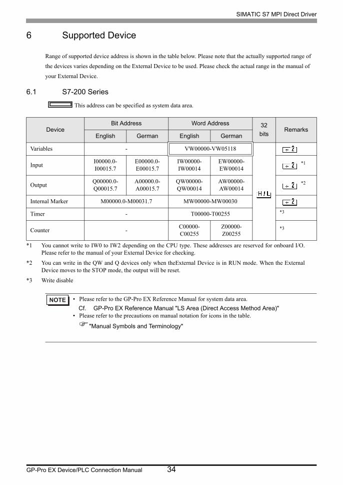
6 Supported Device
Range of supported device address is shown in the table below. Please note that the actually supported range of
the devices varies depending on the External Device to be used. Please check the actual range in the manual of
your External Device.
6.1 S7-200 Series
This address can be specified as system data area.
DeviceBit Address Word Address 32
bitsRemarks
English German English German
Variables - VW00000-VW05118
InputI00000.0-I00015.7
E00000.0-E00015.7
IW00000-IW00014
EW00000-EW00014
*1
*1 You cannot write to IW0 to IW2 depending on the CPU type. These addresses are reserved for onboard I/O. Please refer to the manual of your External Device for checking.
OutputQ00000.0-Q00015.7
A00000.0-A00015.7
QW00000-QW00014
AW00000-AW00014
*2
*2 You can write in the QW and Q devices only when theExternal Device is in RUN mode. When the External Device moves to the STOP mode, the output will be reset.
Internal Marker M00000.0-M00031.7 MW00000-MW00030
Timer - T00000-T00255 *3
*3 Write disable
Counter -C00000-C00255
Z00000-Z00255
*3
• Please refer to the GP-Pro EX Reference Manual for system data area.
Cf. GP-Pro EX Reference Manual "LS Area (Direct Access Method Area)"• Please refer to the precautions on manual notation for icons in the table.
"Manual Symbols and Terminology"
SIMATIC S7 MPI Direct Driver
GP-Pro EX Device/PLC Connection Manual 35
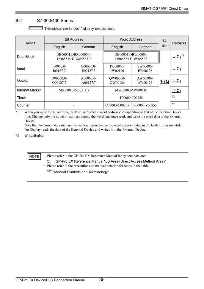
6.2 S7-300/400 Series
This address can be specified as system data area.
DeviceBit Address Word Address 32
bitsRemarks
English German English German
Data BlockDB00001.DBX00000.0-DB65535.DBX65533.7
DB00001.DBW00000-DB65535.DBW65532
*1
*1 When you write the bit address, the Display reads the word address corresponding to that of the External Devicefirst. Change only the target bit address among the word data once read, and write the word data to the External Device.Note that the correct data may not be written if you change the word address value in the ladder program while the Display reads the data of the External Device and writes it to the External Device.
InputI00000.0-I00127.7
E00000.0-E00127.7
IW00000-IW00126
EW00000-EW00126
OutputQ00000.0-Q00127.7
A00000.0-A00127.7
QW00000-QW00126
AW00000-AW00126
Internal Marker M00000.0-M00511.7 MW00000-MW00510
Timer - T00000-T00255 *2
*2 Write disable
Counter - C00000-C00255 Z00000-Z00255 *2
• Please refer to the GP-Pro EX Reference Manual for system data area.
Cf. GP-Pro EX Reference Manual "LS Area (Direct Access Method Area)"• Please refer to the precautions on manual notation for icons in the table.
"Manual Symbols and Terminology"
SIMATIC S7 MPI Direct Driver
GP-Pro EX Device/PLC Connection Manual 36
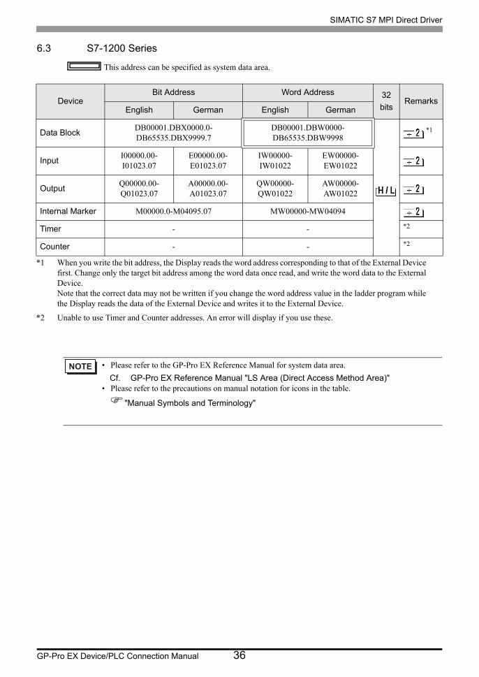
6.3 S7-1200 Series
This address can be specified as system data area.
DeviceBit Address Word Address 32
bitsRemarks
English German English German
Data BlockDB00001.DBX0000.0-DB65535.DBX9999.7
DB00001.DBW0000-DB65535.DBW9998
*1
*1 When you write the bit address, the Display reads the word address corresponding to that of the External Devicefirst. Change only the target bit address among the word data once read, and write the word data to the External Device.Note that the correct data may not be written if you change the word address value in the ladder program while the Display reads the data of the External Device and writes it to the External Device.
InputI00000.00-I01023.07
E00000.00-E01023.07
IW00000-IW01022
EW00000-EW01022
OutputQ00000.00-Q01023.07
A00000.00-A01023.07
QW00000-QW01022
AW00000-AW01022
Internal Marker M00000.0-M04095.07 MW00000-MW04094
Timer - - *2
*2 Unable to use Timer and Counter addresses. An error will display if you use these.
Counter - - *2
• Please refer to the GP-Pro EX Reference Manual for system data area.
Cf. GP-Pro EX Reference Manual "LS Area (Direct Access Method Area)"• Please refer to the precautions on manual notation for icons in the table.
"Manual Symbols and Terminology"
SIMATIC S7 MPI Direct Driver
GP-Pro EX Device/PLC Connection Manual 37
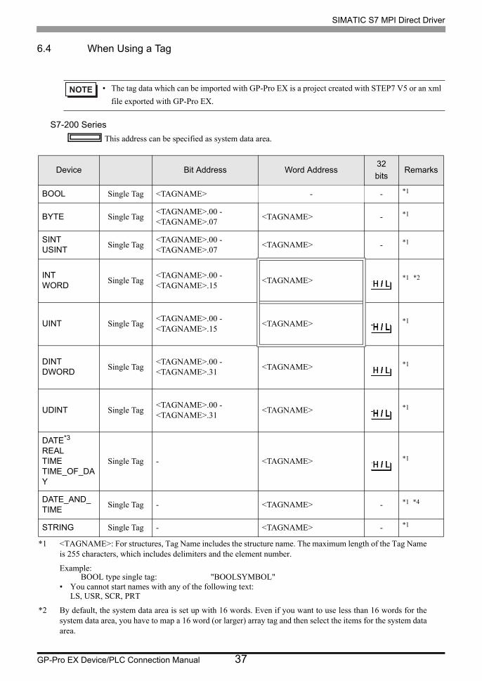
6.4 When Using a Tag
S7-200 Series
This address can be specified as system data area.
• The tag data which can be imported with GP-Pro EX is a project created with STEP7 V5 or an xml
file exported with GP-Pro EX.
Device Bit Address Word Address32
bitsRemarks
BOOL Single Tag <TAGNAME> - - *1
*1 <TAGNAME>: For structures, Tag Name includes the structure name. The maximum length of the Tag Name is 255 characters, which includes delimiters and the element number.
Example:BOOL type single tag: "BOOLSYMBOL"
• You cannot start names with any of the following text:LS, USR, SCR, PRT
BYTE Single Tag<TAGNAME>.00 - <TAGNAME>.07
<TAGNAME> - *1
SINTUSINT
Single Tag<TAGNAME>.00 - <TAGNAME>.07
<TAGNAME> - *1
INTWORD
Single Tag<TAGNAME>.00 - <TAGNAME>.15
<TAGNAME> *1 *2
*2 By default, the system data area is set up with 16 words. Even if you want to use less than 16 words for the system data area, you have to map a 16 word (or larger) array tag and then select the items for the system data area.
UINT Single Tag<TAGNAME>.00 - <TAGNAME>.15
<TAGNAME> *1
DINTDWORD
Single Tag<TAGNAME>.00 - <TAGNAME>.31
<TAGNAME> *1
UDINT Single Tag<TAGNAME>.00 - <TAGNAME>.31
<TAGNAME> *1
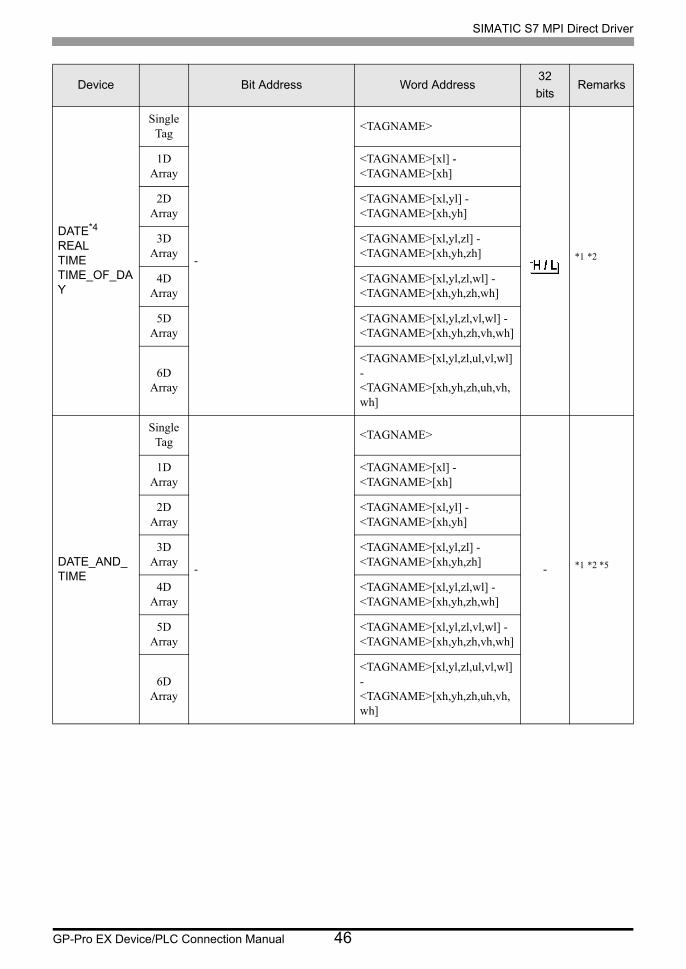
DATE*3
REALTIMETIME_OF_DAY
Single Tag - <TAGNAME> *1
DATE_AND_TIME
Single Tag - <TAGNAME> - *1 *4
STRING Single Tag - <TAGNAME> - *1
SIMATIC S7 MPI Direct Driver
GP-Pro EX Device/PLC Connection Manual 38
*3 Handled as 16-bit devices in the External Device, but as 32-bit devices in GP-Pro EX.
*4 64-bit device
• You cannot import S7-200 series tag data (symbol addresses).• The tag import feature is supported in GP-Pro EX V3.01.000 or later (or in the case
of GP-4*01TM, V3.10.000 or later).
• Please refer to the GP-Pro EX Reference Manual for system data area.
Cf. GP-Pro EX Reference Manual "LS Area (Direct Access Method Area)"• Please refer to the precautions on manual notation for icons in the table.
"Manual Symbols and Terminology"
SIMATIC S7 MPI Direct Driver
GP-Pro EX Device/PLC Connection Manual 39
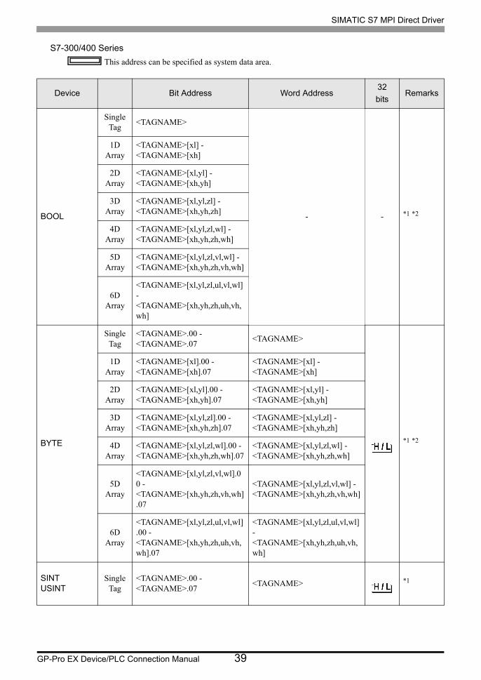
S7-300/400 Series
This address can be specified as system data area.
Device Bit Address Word Address32
bitsRemarks
BOOL
Single Tag
<TAGNAME>
- - *1 *2
1D Array
<TAGNAME>[xl] - <TAGNAME>[xh]
2D Array
<TAGNAME>[xl,yl] - <TAGNAME>[xh,yh]
3D Array
<TAGNAME>[xl,yl,zl] - <TAGNAME>[xh,yh,zh]
4D Array
<TAGNAME>[xl,yl,zl,wl] - <TAGNAME>[xh,yh,zh,wh]
5D Array
<TAGNAME>[xl,yl,zl,vl,wl] - <TAGNAME>[xh,yh,zh,vh,wh]
6D Array
<TAGNAME>[xl,yl,zl,ul,vl,wl] - <TAGNAME>[xh,yh,zh,uh,vh,wh]
BYTE
Single Tag
<TAGNAME>.00 - <TAGNAME>.07
<TAGNAME>
*1 *2
1D Array
<TAGNAME>[xl].00 - <TAGNAME>[xh].07
<TAGNAME>[xl] - <TAGNAME>[xh]
2D Array
<TAGNAME>[xl,yl].00 - <TAGNAME>[xh,yh].07
<TAGNAME>[xl,yl] - <TAGNAME>[xh,yh]
3D Array
<TAGNAME>[xl,yl,zl].00 - <TAGNAME>[xh,yh,zh].07
<TAGNAME>[xl,yl,zl] - <TAGNAME>[xh,yh,zh]
4D Array
<TAGNAME>[xl,yl,zl,wl].00 - <TAGNAME>[xh,yh,zh,wh].07
<TAGNAME>[xl,yl,zl,wl] - <TAGNAME>[xh,yh,zh,wh]
5D Array
<TAGNAME>[xl,yl,zl,vl,wl].00 - <TAGNAME>[xh,yh,zh,vh,wh].07
<TAGNAME>[xl,yl,zl,vl,wl] - <TAGNAME>[xh,yh,zh,vh,wh]
6D Array
<TAGNAME>[xl,yl,zl,ul,vl,wl].00 - <TAGNAME>[xh,yh,zh,uh,vh,wh].07
<TAGNAME>[xl,yl,zl,ul,vl,wl] - <TAGNAME>[xh,yh,zh,uh,vh,wh]
SINTUSINT
Single Tag
<TAGNAME>.00 - <TAGNAME>.07
<TAGNAME> *1

SIMATIC S7 MPI Direct Driver
GP-Pro EX Device/PLC Connection Manual 40
INTWORD
Single Tag
<TAGNAME>.00 - <TAGNAME>.15
<TAGNAME>
*1 *2 *3
1D Array
<TAGNAME>[xl].00 - <TAGNAME>[xh].15
<TAGNAME>[xl] - <TAGNAME>[xh]
2D Array
<TAGNAME>[xl,yl].00 - <TAGNAME>[xh,yh].15
<TAGNAME>[xl,yl] - <TAGNAME>[xh,yh]
3D Array
<TAGNAME>[xl,yl,zl].00 - <TAGNAME>[xh,yh,zh].15
<TAGNAME>[xl,yl,zl] - <TAGNAME>[xh,yh,zh]
4D Array
<TAGNAME>[xl,yl,zl,wl].00 - <TAGNAME>[xh,yh,zh,wh].15
<TAGNAME>[xl,yl,zl,wl] - <TAGNAME>[xh,yh,zh,wh]
5D Array
<TAGNAME>[xl,yl,zl,vl,wl].00 - <TAGNAME>[xh,yh,zh,vh,wh].15
<TAGNAME>[xl,yl,zl,vl,wl] - <TAGNAME>[xh,yh,zh,vh,wh]
6D Array
<TAGNAME>[xl,yl,zl,ul,vl,wl].00 - <TAGNAME>[xh,yh,zh,uh,vh,wh].15
<TAGNAME>[xl,yl,zl,ul,vl,wl] - <TAGNAME>[xh,yh,zh,uh,vh,wh]
UINTSingle
Tag<TAGNAME>.00 - <TAGNAME>.15
<TAGNAME> *1
DINTDWORD
Single Tag
<TAGNAME>.00 - <TAGNAME>.31
<TAGNAME>
*1 *2
1D Array
<TAGNAME>[xl].00 - <TAGNAME>[xh].31
<TAGNAME>[xl] - <TAGNAME>[xh]
2D Array
<TAGNAME>[xl,yl].00 - <TAGNAME>[xh,yh].31
<TAGNAME>[xl,yl] - <TAGNAME>[xh,yh]
3D Array
<TAGNAME>[xl,yl,zl].00 - <TAGNAME>[xh,yh,zh].31
<TAGNAME>[xl,yl,zl] - <TAGNAME>[xh,yh,zh]
4D Array
<TAGNAME>[xl,yl,zl,wl].00 - <TAGNAME>[xh,yh,zh,wh].31
<TAGNAME>[xl,yl,zl,wl] - <TAGNAME>[xh,yh,zh,wh]
5D Array
<TAGNAME>[xl,yl,zl,vl,wl].00 - <TAGNAME>[xh,yh,zh,vh,wh].31
<TAGNAME>[xl,yl,zl,vl,wl] - <TAGNAME>[xh,yh,zh,vh,wh]
6D Array
<TAGNAME>[xl,yl,zl,ul,vl,wl].00 - <TAGNAME>[xh,yh,zh,uh,vh,wh].31
<TAGNAME>[xl,yl,zl,ul,vl,wl] - <TAGNAME>[xh,yh,zh,uh,vh,wh]
UDINTSingle
Tag<TAGNAME>.00 - <TAGNAME>.31
<TAGNAME> *1
Device Bit Address Word Address32
bitsRemarks

SIMATIC S7 MPI Direct Driver
GP-Pro EX Device/PLC Connection Manual 41
DATE*4
REALTIMETIME_OF_DAY
Single Tag
-
<TAGNAME>
*1 *2
1D Array
<TAGNAME>[xl] - <TAGNAME>[xh]
2D Array
<TAGNAME>[xl,yl] - <TAGNAME>[xh,yh]
3D Array
<TAGNAME>[xl,yl,zl] - <TAGNAME>[xh,yh,zh]
4D Array
<TAGNAME>[xl,yl,zl,wl] - <TAGNAME>[xh,yh,zh,wh]
5D Array
<TAGNAME>[xl,yl,zl,vl,wl] - <TAGNAME>[xh,yh,zh,vh,wh]
6D Array
<TAGNAME>[xl,yl,zl,ul,vl,wl] - <TAGNAME>[xh,yh,zh,uh,vh,wh]
DATE_AND_TIME
Single Tag
-
<TAGNAME>
- *1 *2 *5
1D Array
<TAGNAME>[xl] - <TAGNAME>[xh]
2D Array
<TAGNAME>[xl,yl] - <TAGNAME>[xh,yh]
3D Array
<TAGNAME>[xl,yl,zl] - <TAGNAME>[xh,yh,zh]
4D Array
<TAGNAME>[xl,yl,zl,wl] - <TAGNAME>[xh,yh,zh,wh]
5D Array
<TAGNAME>[xl,yl,zl,vl,wl] - <TAGNAME>[xh,yh,zh,vh,wh]
6D Array
<TAGNAME>[xl,yl,zl,ul,vl,wl] - <TAGNAME>[xh,yh,zh,uh,vh,wh]
Device Bit Address Word Address32
bitsRemarks
SIMATIC S7 MPI Direct Driver
GP-Pro EX Device/PLC Connection Manual 42
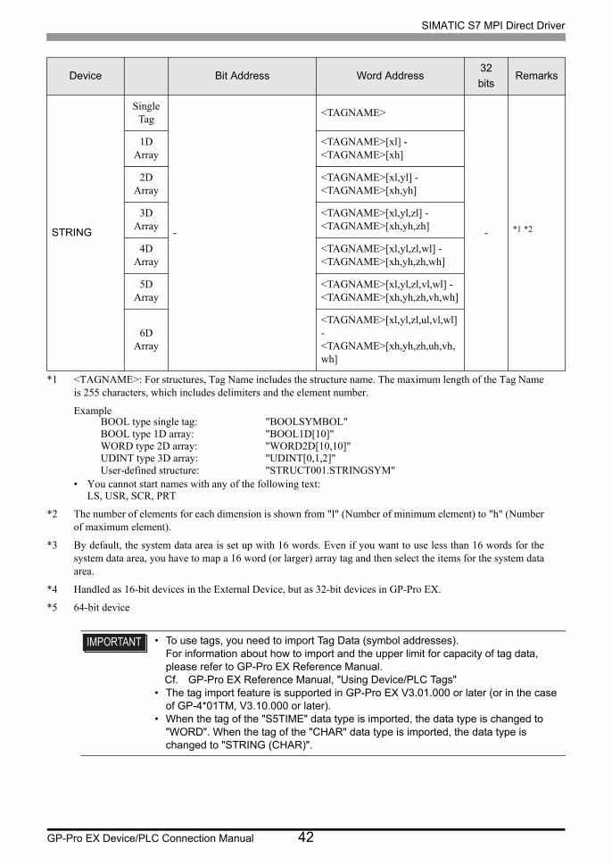
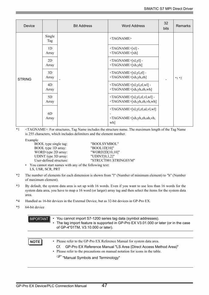
STRING
Single Tag
-
<TAGNAME>
- *1 *2
1D Array
<TAGNAME>[xl] - <TAGNAME>[xh]
2D Array
<TAGNAME>[xl,yl] - <TAGNAME>[xh,yh]
3D Array
<TAGNAME>[xl,yl,zl] - <TAGNAME>[xh,yh,zh]
4D Array
<TAGNAME>[xl,yl,zl,wl] - <TAGNAME>[xh,yh,zh,wh]
5D Array
<TAGNAME>[xl,yl,zl,vl,wl] - <TAGNAME>[xh,yh,zh,vh,wh]
6D Array
<TAGNAME>[xl,yl,zl,ul,vl,wl] - <TAGNAME>[xh,yh,zh,uh,vh,wh]
*1 <TAGNAME>: For structures, Tag Name includes the structure name. The maximum length of the Tag Name is 255 characters, which includes delimiters and the element number.
ExampleBOOL type single tag: "BOOLSYMBOL"BOOL type 1D array: "BOOL1D[10]"WORD type 2D array: "WORD2D[10,10]"UDINT type 3D array: "UDINT[0,1,2]"User-defined structure: "STRUCT001.STRINGSYM"
• You cannot start names with any of the following text:LS, USR, SCR, PRT
*2 The number of elements for each dimension is shown from "l" (Number of minimum element) to "h" (Number of maximum element).
*3 By default, the system data area is set up with 16 words. Even if you want to use less than 16 words for the system data area, you have to map a 16 word (or larger) array tag and then select the items for the system data area.
*4 Handled as 16-bit devices in the External Device, but as 32-bit devices in GP-Pro EX.
*5 64-bit device
• To use tags, you need to import Tag Data (symbol addresses).For information about how to import and the upper limit for capacity of tag data, please refer to GP-Pro EX Reference Manual.Cf. GP-Pro EX Reference Manual, "Using Device/PLC Tags"
• The tag import feature is supported in GP-Pro EX V3.01.000 or later (or in the case of GP-4*01TM, V3.10.000 or later).
• When the tag of the "S5TIME" data type is imported, the data type is changed to "WORD". When the tag of the "CHAR" data type is imported, the data type is changed to "STRING (CHAR)".
Device Bit Address Word Address32
bitsRemarks
SIMATIC S7 MPI Direct Driver
GP-Pro EX Device/PLC Connection Manual 43
• Please refer to the GP-Pro EX Reference Manual for system data area.
Cf. GP-Pro EX Reference Manual "LS Area (Direct Access Method Area)"• Please refer to the precautions on manual notation for icons in the table.
"Manual Symbols and Terminology"

SIMATIC S7 MPI Direct Driver
GP-Pro EX Device/PLC Connection Manual 44
S7-1200 Series
This address can be specified as system data area.
Device Bit Address Word Address32
bitsRemarks
BOOL
Single Tag
<TAGNAME>
- - *1 *2
1D Array
<TAGNAME>[xl] - <TAGNAME>[xh]
2D Array
<TAGNAME>[xl,yl] - <TAGNAME>[xh,yh]
3D Array
<TAGNAME>[xl,yl,zl] - <TAGNAME>[xh,yh,zh]
4D Array
<TAGNAME>[xl,yl,zl,wl] - <TAGNAME>[xh,yh,zh,wh]
5D Array
<TAGNAME>[xl,yl,zl,vl,wl] - <TAGNAME>[xh,yh,zh,vh,wh]
6D Array
<TAGNAME>[xl,yl,zl,ul,vl,wl] - <TAGNAME>[xh,yh,zh,uh,vh,wh]
BYTE
Single Tag
<TAGNAME>.00 - <TAGNAME>.07
<TAGNAME>
*1 *2
1D Array
<TAGNAME>[xl].00 - <TAGNAME>[xh].07
<TAGNAME>[xl] - <TAGNAME>[xh]
2D Array
<TAGNAME>[xl,yl].00 - <TAGNAME>[xh,yh].07
<TAGNAME>[xl,yl] - <TAGNAME>[xh,yh]
3D Array
<TAGNAME>[xl,yl,zl].00 - <TAGNAME>[xh,yh,zh].07
<TAGNAME>[xl,yl,zl] - <TAGNAME>[xh,yh,zh]
4D Array
<TAGNAME>[xl,yl,zl,wl].00 - <TAGNAME>[xh,yh,zh,wh].07
<TAGNAME>[xl,yl,zl,wl] - <TAGNAME>[xh,yh,zh,wh]
5D Array
<TAGNAME>[xl,yl,zl,vl,wl].00 - <TAGNAME>[xh,yh,zh,vh,wh].07
<TAGNAME>[xl,yl,zl,vl,wl] - <TAGNAME>[xh,yh,zh,vh,wh]
6D Array
<TAGNAME>[xl,yl,zl,ul,vl,wl].00 - <TAGNAME>[xh,yh,zh,uh,vh,wh].07
<TAGNAME>[xl,yl,zl,ul,vl,wl] - <TAGNAME>[xh,yh,zh,uh,vh,wh]
SINTUSINT
Single Tag
<TAGNAME>.00 - <TAGNAME>.07
<TAGNAME> *1
SIMATIC S7 MPI Direct Driver
GP-Pro EX Device/PLC Connection Manual 45
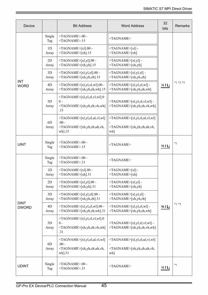
INTWORD
Single Tag
<TAGNAME>.00 - <TAGNAME>.15
<TAGNAME>
*1 *2 *3
1D Array
<TAGNAME>[xl].00 - <TAGNAME>[xh].15
<TAGNAME>[xl] - <TAGNAME>[xh]
2D Array
<TAGNAME>[xl,yl].00 - <TAGNAME>[xh,yh].15
<TAGNAME>[xl,yl] - <TAGNAME>[xh,yh]
3D Array
<TAGNAME>[xl,yl,zl].00 - <TAGNAME>[xh,yh,zh].15
<TAGNAME>[xl,yl,zl] - <TAGNAME>[xh,yh,zh]
4D Array
<TAGNAME>[xl,yl,zl,wl].00 - <TAGNAME>[xh,yh,zh,wh].15
<TAGNAME>[xl,yl,zl,wl] - <TAGNAME>[xh,yh,zh,wh]
5D Array
<TAGNAME>[xl,yl,zl,vl,wl].00 - <TAGNAME>[xh,yh,zh,vh,wh].15
<TAGNAME>[xl,yl,zl,vl,wl] - <TAGNAME>[xh,yh,zh,vh,wh]
6D Array
<TAGNAME>[xl,yl,zl,ul,vl,wl].00 - <TAGNAME>[xh,yh,zh,uh,vh,wh].15
<TAGNAME>[xl,yl,zl,ul,vl,wl] - <TAGNAME>[xh,yh,zh,uh,vh,wh]
UINTSingle
Tag<TAGNAME>.00 - <TAGNAME>.15
<TAGNAME> *1
DINTDWORD
Single Tag
<TAGNAME>.00 - <TAGNAME>.31
<TAGNAME>
*1 *2
1D Array
<TAGNAME>[xl].00 - <TAGNAME>[xh].31
<TAGNAME>[xl] - <TAGNAME>[xh]
2D Array
<TAGNAME>[xl,yl].00 - <TAGNAME>[xh,yh].31
<TAGNAME>[xl,yl] - <TAGNAME>[xh,yh]
3D Array
<TAGNAME>[xl,yl,zl].00 - <TAGNAME>[xh,yh,zh].31
<TAGNAME>[xl,yl,zl] - <TAGNAME>[xh,yh,zh]
4D Array
<TAGNAME>[xl,yl,zl,wl].00 - <TAGNAME>[xh,yh,zh,wh].31
<TAGNAME>[xl,yl,zl,wl] - <TAGNAME>[xh,yh,zh,wh]
5D Array
<TAGNAME>[xl,yl,zl,vl,wl].00 - <TAGNAME>[xh,yh,zh,vh,wh].31
<TAGNAME>[xl,yl,zl,vl,wl] - <TAGNAME>[xh,yh,zh,vh,wh]
6D Array
<TAGNAME>[xl,yl,zl,ul,vl,wl].00 - <TAGNAME>[xh,yh,zh,uh,vh,wh].31
<TAGNAME>[xl,yl,zl,ul,vl,wl] - <TAGNAME>[xh,yh,zh,uh,vh,wh]
UDINTSingle
Tag<TAGNAME>.00 - <TAGNAME>.31
<TAGNAME> *1
Device Bit Address Word Address32
bitsRemarks
SIMATIC S7 MPI Direct Driver
GP-Pro EX Device/PLC Connection Manual 46
DATE*4
REALTIMETIME_OF_DAY
Single Tag
-
<TAGNAME>
*1 *2
1D Array
<TAGNAME>[xl] - <TAGNAME>[xh]
2D Array
<TAGNAME>[xl,yl] - <TAGNAME>[xh,yh]
3D Array
<TAGNAME>[xl,yl,zl] - <TAGNAME>[xh,yh,zh]
4D Array
<TAGNAME>[xl,yl,zl,wl] - <TAGNAME>[xh,yh,zh,wh]
5D Array
<TAGNAME>[xl,yl,zl,vl,wl] - <TAGNAME>[xh,yh,zh,vh,wh]
6D Array
<TAGNAME>[xl,yl,zl,ul,vl,wl] - <TAGNAME>[xh,yh,zh,uh,vh,wh]
DATE_AND_TIME
Single Tag
-
<TAGNAME>
- *1 *2 *5
1D Array
<TAGNAME>[xl] - <TAGNAME>[xh]
2D Array
<TAGNAME>[xl,yl] - <TAGNAME>[xh,yh]
3D Array
<TAGNAME>[xl,yl,zl] - <TAGNAME>[xh,yh,zh]
4D Array
<TAGNAME>[xl,yl,zl,wl] - <TAGNAME>[xh,yh,zh,wh]
5D Array
<TAGNAME>[xl,yl,zl,vl,wl] - <TAGNAME>[xh,yh,zh,vh,wh]
6D Array
<TAGNAME>[xl,yl,zl,ul,vl,wl] - <TAGNAME>[xh,yh,zh,uh,vh,wh]
Device Bit Address Word Address32
bitsRemarks
SIMATIC S7 MPI Direct Driver
GP-Pro EX Device/PLC Connection Manual 47
STRING
Single Tag
-
<TAGNAME>
- *1 *2
1D Array
<TAGNAME>[xl] - <TAGNAME>[xh]
2D Array
<TAGNAME>[xl,yl] - <TAGNAME>[xh,yh]
3D Array
<TAGNAME>[xl,yl,zl] - <TAGNAME>[xh,yh,zh]
4D Array
<TAGNAME>[xl,yl,zl,wl] - <TAGNAME>[xh,yh,zh,wh]
5D Array
<TAGNAME>[xl,yl,zl,vl,wl] - <TAGNAME>[xh,yh,zh,vh,wh]
6D Array
<TAGNAME>[xl,yl,zl,ul,vl,wl] - <TAGNAME>[xh,yh,zh,uh,vh,wh]
*1 <TAGNAME>: For structures, Tag Name includes the structure name. The maximum length of the Tag Name is 255 characters, which includes delimiters and the element number.
ExampleBOOL type single tag: "BOOLSYMBOL"BOOL type 1D array: "BOOL1D[10]"WORD type 2D array: "WORD2D[10,10]"UDINT type 3D array: "UDINT[0,1,2]"User-defined structure: "STRUCT001.STRINGSYM"
• You cannot start names with any of the following text:LS, USR, SCR, PRT
*2 The number of elements for each dimension is shown from "l" (Number of minimum element) to "h" (Number of maximum element).
*3 By default, the system data area is set up with 16 words. Even if you want to use less than 16 words for the system data area, you have to map a 16 word (or larger) array tag and then select the items for the system data area.
*4 Handled as 16-bit devices in the External Device, but as 32-bit devices in GP-Pro EX.
*5 64-bit device
• You cannot import S7-1200 series tag data (symbol addresses).• The tag import feature is supported in GP-Pro EX V3.01.000 or later (or in the case
of GP-4*01TM, V3.10.000 or later).
• Please refer to the GP-Pro EX Reference Manual for system data area.
Cf. GP-Pro EX Reference Manual "LS Area (Direct Access Method Area)"• Please refer to the precautions on manual notation for icons in the table.
"Manual Symbols and Terminology"
Device Bit Address Word Address32
bitsRemarks
SIMATIC S7 MPI Direct Driver
GP-Pro EX Device/PLC Connection Manual 48
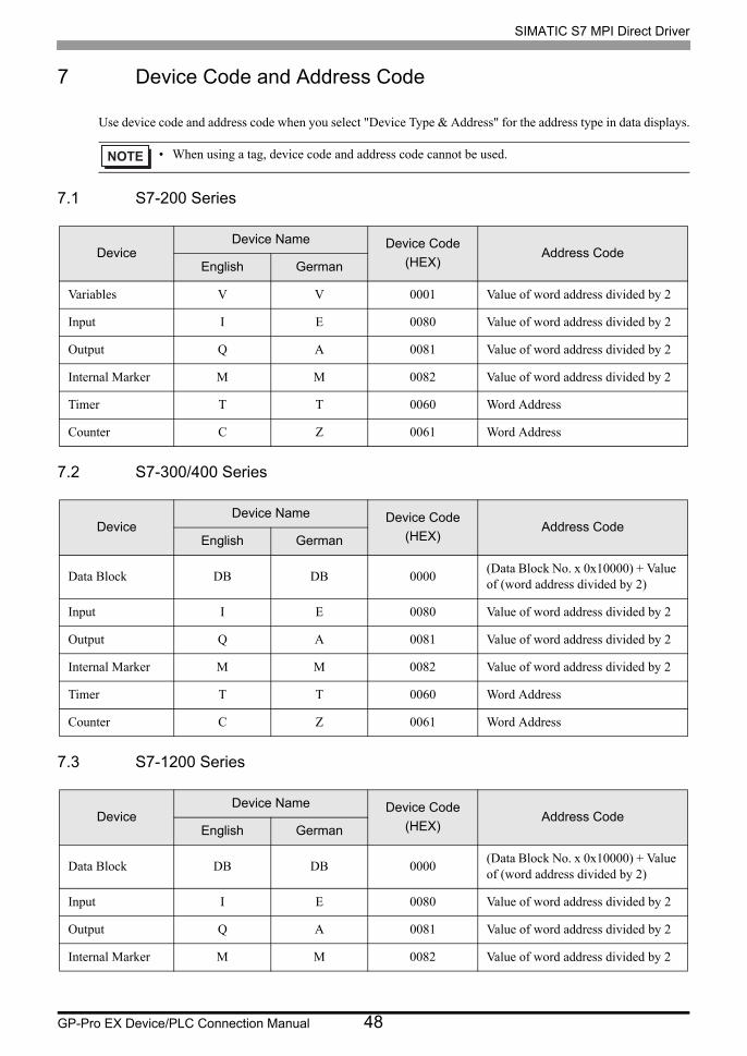
7 Device Code and Address Code
Use device code and address code when you select "Device Type & Address" for the address type in data displays.
7.1 S7-200 Series
7.2 S7-300/400 Series
7.3 S7-1200 Series
• When using a tag, device code and address code cannot be used.
DeviceDevice Name Device Code
(HEX)Address Code
English German
Variables V V 0001 Value of word address divided by 2
Input I E 0080 Value of word address divided by 2
Output Q A 0081 Value of word address divided by 2
Internal Marker M M 0082 Value of word address divided by 2
Timer T T 0060 Word Address
Counter C Z 0061 Word Address
DeviceDevice Name Device Code
(HEX)Address Code
English German
Data Block DB DB 0000(Data Block No. x 0x10000) + Value of (word address divided by 2)
Input I E 0080 Value of word address divided by 2
Output Q A 0081 Value of word address divided by 2
Internal Marker M M 0082 Value of word address divided by 2
SIMATIC S7 MPI Direct Driver
GP-Pro EX Device/PLC Connection Manual 49
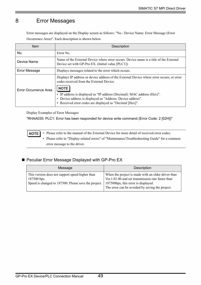
8 Error Messages
Error messages are displayed on the Display screen as follows: "No.: Device Name: Error Message (Error
Occurrence Area)". Each description is shown below.
Display Examples of Error Messages
"RHAA035: PLC1: Error has been responded for device write command (Error Code: 2 [02H])"
Peculiar Error Message Displayed with GP-Pro EX
Item Description
No. Error No.
Device NameName of the External Device where error occurs. Device name is a title of the External Device set with GP-Pro EX. (Initial value [PLC1])
Error Message Displays messages related to the error which occurs.
Error Occurrence Area
Displays IP address or device address of the External Device where error occurs, or error codes received from the External Device.
• IP address is displayed as "IP address (Decimal): MAC address (Hex)".• Device address is displayed as "Address: Device address".• Received error codes are displayed as "Decimal [Hex]".
• Please refer to the manual of the External Device for more detail of received error codes.
• Please refer to "Display-related errors" of "Maintenance/Troubleshooting Guide" for a common
error message to the driver.
Message Description
This version does not support speed higher than 187500 bps.Speed is changed to 187500. Please save the project.
When the project is made with an older driver than Ver.1.01.00 and set transmission rate faster than 187500bps, this error is displayed.The error can be avoided by saving the project.
SIMATIC S7 MPI Direct Driver
GP-Pro EX Device/PLC Connection Manual 50
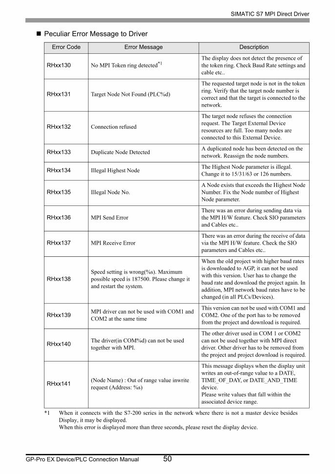
Peculiar Error Message to Driver
Error Code Error Message Description
RHxx130 No MPI Token ring detected*1
*1 When it connects with the S7-200 series in the network where there is not a master device besides Display, it may be displayed. When this error is displayed more than three seconds, please reset the display device.
The display does not detect the presence of the token ring. Check Baud Rate settings and cable etc..
RHxx131 Target Node Not Found (PLC%d)
The requested target node is not in the token ring. Verify that the target node number is correct and that the target is connected to the network.
RHxx132 Connection refused
The target node refuses the connection request. The Target External Device resources are full. Too many nodes are connected to this External Device.
RHxx133 Duplicate Node DetectedA duplicated node has been detected on the network. Reassign the node numbers.
RHxx134 Illegal Highest NodeThe Highest Node parameter is illegal. Change it to 15/31/63 or 126 numbers.
RHxx135 Illegal Node No.A Node exists that exceeds the Highest Node Number. Fix the Node number of Highest Node parameter.
RHxx136 MPI Send ErrorThere was an error during sending data via the MPI H/W feature. Check SIO parameters and Cables etc..
RHxx137 MPI Receive ErrorThere was an error during the receive of data via the MPI H/W feature. Check the SIO parameters and Cables etc..
RHxx138Speed setting is wrong(%s). Maximum possible speed is 187500. Please change it and restart the system.
When the old project with higher baud rates is downloaded to AGP, it can not be used with this version. User has to change the baud rate and download the project again. In addition, MPI network baud rates have to be changed (in all PLCs/Devices).
RHxx139MPI driver can not be used with COM1 and COM2 at the same time
This version can not be used with COM1 and COM2. One of the port has to be removed from the project and download is required.
RHxx140The driver(in COM%d) can not be used together with MPI.
The other driver used in COM 1 or COM2 can not be used together with MPI direct driver. Other driver has to be removed from the project and project download is required.
RHxx141(Node Name) : Out of range value inwrite request (Address: %s)
This message displays when the display unit writes an out-of-range value to a DATE, TIME_OF_DAY, or DATE_AND_TIME device. Please write values that fall within the associated device range.