si real-time system components - seismic instruments
TRANSCRIPT

w w w . s e i s m i c i n s t r u m e n t s . c o m
Page 1
w w w . s e i s m i c i n s t r u m e n t s . c o m
Page 2
Seismic Instruments offers three different configurations of data acquisition system (Cabled, Cable-Free and Mixed) in a wide range of options, and SI also offers two smaller setups (Electromagnetic and Small-Scale Engineering).
Based on our proprietary Smart Geophone (SMG) technology, one of SI's original products is the Cabled edition of the Smart System for use in 2D or 3D seismic data gathering applications. This Real Time Data Acquisition System is available in a variety of configurations, depending on the channel count and intended use.
The Cabled Systems are designed to take advantage of the latest communications and commercial off-the-shelf (COTS) technology. This increases reliability and maintainability, while at the same time helping to make single-sensor recording cost-competitive with older data acquisition techniques.
Based on a modular architecture of intelligent components, the data acquisition system:
Can be scaled from 6 to 100,000+ channels, 2-D or 3-D Is used for Real Time High Resolution Data Acquisition Can easily be tailored and reconfigured to a customer’s individual needs Provides quicker, more accurate troubleshooting Allows fast deployment and higher productivity
List of equipment in a Cabled (Real Time) data acquisition system:
A/ Central recording system
1. Operator Console Computer 2. Central Recording Unit (CRU) 3. Source control system 4. SI Engineering software
B/ Field Equipment
1. Hybrid Smart Line Interface Module (HSLIM) 2. Smart Geophone (SMG) String (2 Strings/HSLIM) 3. Battery Booster Unit (BBU) 4. Line Repeater (LRPTR) 5. Line Cable
w w w . s e i s m i c i n s t r u m e n t s . c o m
Page 3
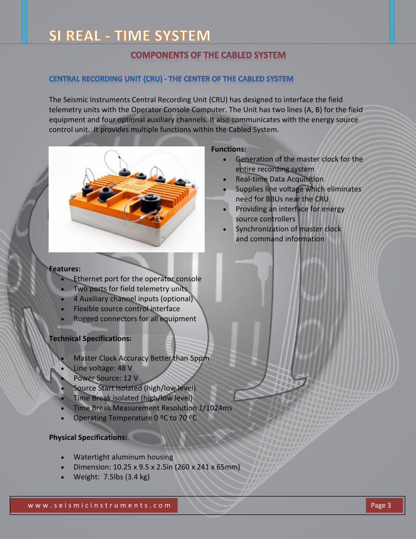
The Seismic Instruments Central Recording Unit (CRU) has designed to interface the field telemetry units with the Operator Console Computer. The Unit has two lines (A, B) for the field equipment and four optional auxiliary channels. It also communicates with the energy source control unit. It provides multiple functions within the Cabled System.
Functions: Generation of the master clock for the
entire recording system Real-time Data Acquisition Supplies line voltage which eliminates
need for BBUs near the CRU Providing an interface for energy
source controllers Synchronization of master clock
and command information
Features: Ethernet port for the operator console Two ports for field telemetry units 4 Auxiliary channel inputs (optional) Flexible source control interface Rugged connectors for all equipment
Technical Specifications:
Master Clock Accuracy Better than 5ppm Line voltage: 48 V Power Source: 12 V Source Start isolated (high/low level) Time Break isolated (high/low level) Time Break Measurement Resolution 1/1024ms Operating Temperature 0 ºC to 70 ºC
Physical Specifications:
Watertight aluminum housing Dimension: 10.25 x 9.5 x 2.5in (260 x 241 x 65mm) Weight: 7.5lbs (3.4 kg)
w w w . s e i s m i c i n s t r u m e n t s . c o m
Page 4
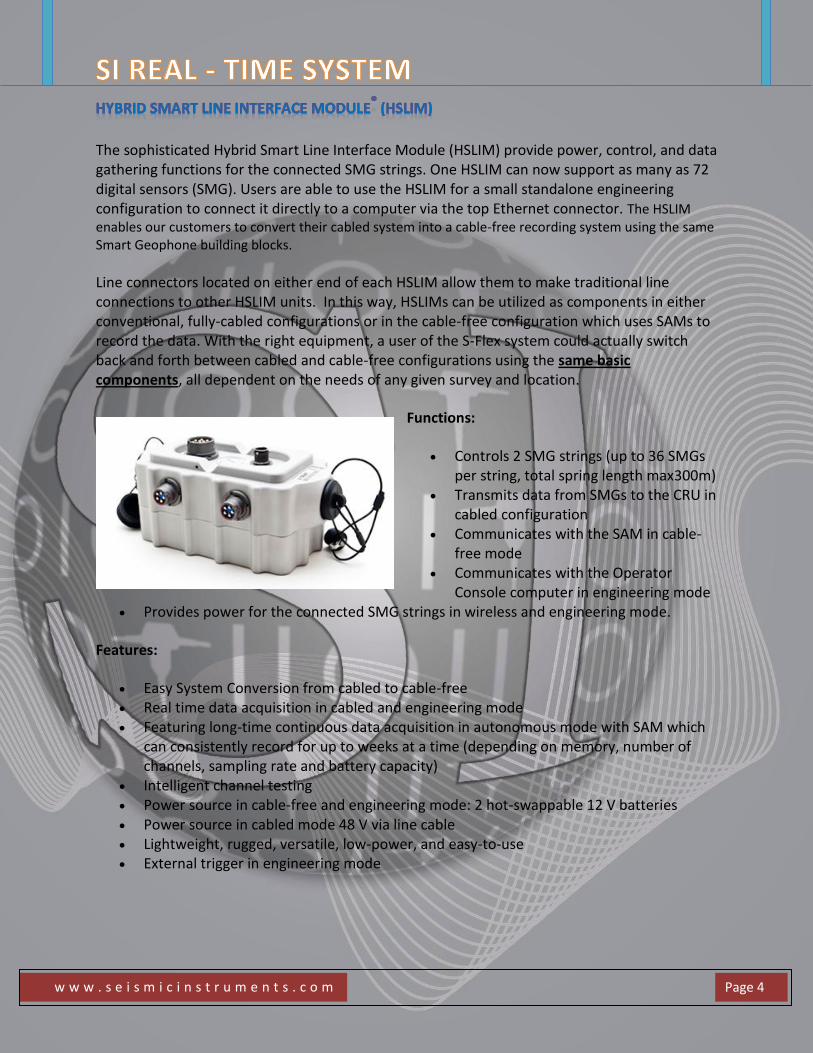
The sophisticated Hybrid Smart Line Interface Module (HSLIM) provide power, control, and data gathering functions for the connected SMG strings. One HSLIM can now support as many as 72 digital sensors (SMG). Users are able to use the HSLIM for a small standalone engineering configuration to connect it directly to a computer via the top Ethernet connector. The HSLIM enables our customers to convert their cabled system into a cable-free recording system using the same Smart Geophone building blocks.
Line connectors located on either end of each HSLIM allow them to make traditional line connections to other HSLIM units. In this way, HSLIMs can be utilized as components in either conventional, fully-cabled configurations or in the cable-free configuration which uses SAMs to record the data. With the right equipment, a user of the S-Flex system could actually switch back and forth between cabled and cable-free configurations using the same basic components, all dependent on the needs of any given survey and location.
Functions:
Controls 2 SMG strings (up to 36 SMGs per string, total spring length max300m)
Transmits data from SMGs to the CRU in cabled configuration
Communicates with the SAM in cable- free mode
Communicates with the Operator Console computer in engineering mode
Provides power for the connected SMG strings in wireless and engineering mode.
Features:
Easy System Conversion from cabled to cable-free Real time data acquisition in cabled and engineering mode Featuring long-time continuous data acquisition in autonomous mode with SAM which
can consistently record for up to weeks at a time (depending on memory, number of channels, sampling rate and battery capacity)
Intelligent channel testing Power source in cable-free and engineering mode: 2 hot-swappable 12 V batteries Power source in cabled mode 48 V via line cable Lightweight, rugged, versatile, low-power, and easy-to-use External trigger in engineering mode
w w w . s e i s m i c i n s t r u m e n t s . c o m
Page 5
Technical Specifications:
Data Transmission Speed 100 Mb/s Up to 72 channels controlled Power consumption: 1.8 W Operating Temperature: -40 ºC to 75 ºC
Physical specifications:
Watertight aluminum housing Dimensions: 4.7 x 2.7 x 2 in (119 x 69 x 50 mm) Weight: 3.3 lbs (1.5 kg)
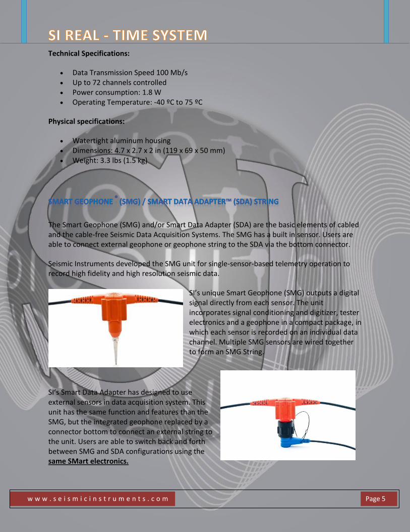
The Smart Geophone (SMG) and/or Smart Data Adapter (SDA) are the basic elements of cabled and the cable-free Seismic Data Acquisition Systems. The SMG has a built in sensor. Users are able to connect external geophone or geophone string to the SDA via the bottom connector.
Seismic Instruments developed the SMG unit for single-sensor-based telemetry operation to record high fidelity and high resolution seismic data.
SI’s unique Smart Geophone (SMG) outputs a digital signal directly from each sensor. The unit incorporates signal conditioning and digitizer, tester electronics and a geophone in a compact package, in which each sensor is recorded on an individual data channel. Multiple SMG sensors are wired together to form an SMG String.
SI’s Smart Data Adapter has designed to use external sensors in data acquisition system. This unit has the same function and features than the SMG, but the integrated geophone replaced by a connector bottom to connect an external string to the unit. Users are able to switch back and forth between SMG and SDA configurations using the same SMart electronics.
w w w . s e i s m i c i n s t r u m e n t s . c o m
Page 6
An SMG string consists of four basic components:
A string connector which plugs into a Smart Line Interface Module (SLIM). SMGs Cable segments which run between SMGs. A string terminator which is located at the end of the string.
The number of SMGs in the digital string is user definable. Thanks to the modular design it is easily reconfigurable based on the proper prospect. Consequently, each sensor in a spread can be individually tested for performance and correct deployment, utilizing SI's innovative and intuitive proprietary software.
The SMG is the smallest and lightest digitizer unit in the seismic data acquisition market.
Functions:
Conditioning and digitalization of incoming seismic signals Interpretation of command, returning status and geophone response in digital format
via a twisted quad wire telemetry bus Built-in performance tests for each geophone and electronics Eliminates noise-prone analog wiring runs Advanced fault and tilt detection
Features:
Optimized for single-sensor recording Modular package for quick string reconfiguration Tower-type flexible sensor board Integrated Geophones (SMG only):
Oyo Geospace GS-30CT Oyo Geospace GS-20DH Omni Other type for customer request
Connector bottom for LCK-series geophone string connector (SDA only) Connector bottom with Low Noise Amplifier for LCK-series geophone string connector
for micro seismic applications (SDA only) Electronic Performance tests: Offset, Noise, Dynamic range, Distortion, Impulse Geophone Performance tests: Natural frequency, Damping, Impulse Environment/Telemetry tests: Offset, Noise, Impulse Eliminates noise-prone analog wiring runs Allows you to upgrade your existing analog geophones, if desired No irreversible changes occur to the data during recording Strings are easily reconfigurable Easy SMG replacement on the field
w w w . s e i s m i c i n s t r u m e n t s . c o m
Page 7
Specifications:
Input Impedance: 1 k Ohm damping (>25 without damping), || 5 nF Preamp Gains: 0 dB, 12 dB, 24 dB, 36 dB Full Scale Input Levels:
0 dB 5 Vpp 12 dB 1.25 Vpp 24 dB 312.5 mVpp 36 dB 78.1 mVpp
Offset digitally zeroed at all gains (switchable) Common to Differential Mode Rejection: 120 dB @ 50Hz, 500mVpp 24-bit analog-to-digital conversion Fourth-order Delta-Sigma architecture Sampling Interval (ms): 0.25, 0.5, 1, 2 Bandwidth (-3 dB): 0.856 Nyquist frequency (428 Hz @ 1 ms) Frequency Range: DC to 1600 Hz @ 0.25 ms Sample Interval Stop Band Attenuation: (above Nyquist measured -6 dB below full scale) > 130 dB Passband Ripple: (below 400 Hz) 0.01 dB digitizer; Passband Phase Characteristic: linear digitizer; Phase accuracy: 15 µs Dynamic Range: 119 dB @ 2 ms Sample Interval, 24 dB Gain Signal to Noise Ratio: (digitizer; 800 Ohm terminated input)
0 dB 123 dB (typ) > 120 dB 12 dB 122 dB (typ) > 118dB 24 dB 115 dB (typ) > 112dB 36 dB 103 dB (typ) > 100 dB
Total Harmonic Distortion: (digitizer; measured -6dB below full scale, 31.25Hz) 0 dB 0.00009 (typ) 0.0002 (max) 12 dB 0.0001 (typ) 24 dB 0.0001 (typ) 36 dB 0.00015 (typ)
Gain Accuracy digitizer;: (absolute) 1% (typical) Gain Accuracy digitizer;: (relative at different gains) 0.4% (typical) Power Consumption: 210 mW (typical) Operating Temperature: -40 ºC to 75 ºC
w w w . s e i s m i c i n s t r u m e n t s . c o m
Page 8
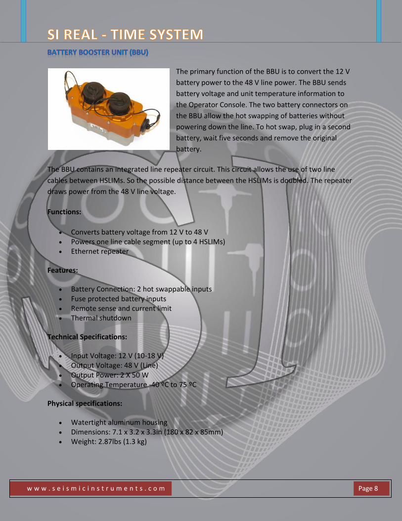
The primary function of the BBU is to convert the 12 V
battery power to the 48 V line power. The BBU sends
battery voltage and unit temperature information to
the Operator Console. The two battery connectors on
the BBU allow the hot swapping of batteries without
powering down the line. To hot swap, plug in a second
battery, wait five seconds and remove the original
battery.
The BBU contains an integrated line repeater circuit. This circuit allows the use of two line
cables between HSLIMs. So the possible distance between the HSLIMs is doubled. The repeater
draws power from the 48 V line voltage.
Functions:
Converts battery voltage from 12 V to 48 V Powers one line cable segment (up to 4 HSLIMs) Ethernet repeater
Features:
Battery Connection: 2 hot swappable inputs Fuse protected battery inputs Remote sense and current limit Thermal shutdown
Technical Specifications:
Input Voltage: 12 V (10-18 V) Output Voltage: 48 V (Line) Output Power: 2 X 50 W Operating Temperature -40 ºC to 75 ºC
Physical specifications:
Watertight aluminum housing Dimensions: 7.1 x 3.2 x 3.3in (180 x 82 x 85mm) Weight: 2.87lbs (1.3 kg)
w w w . s e i s m i c i n s t r u m e n t s . c o m
Page 9
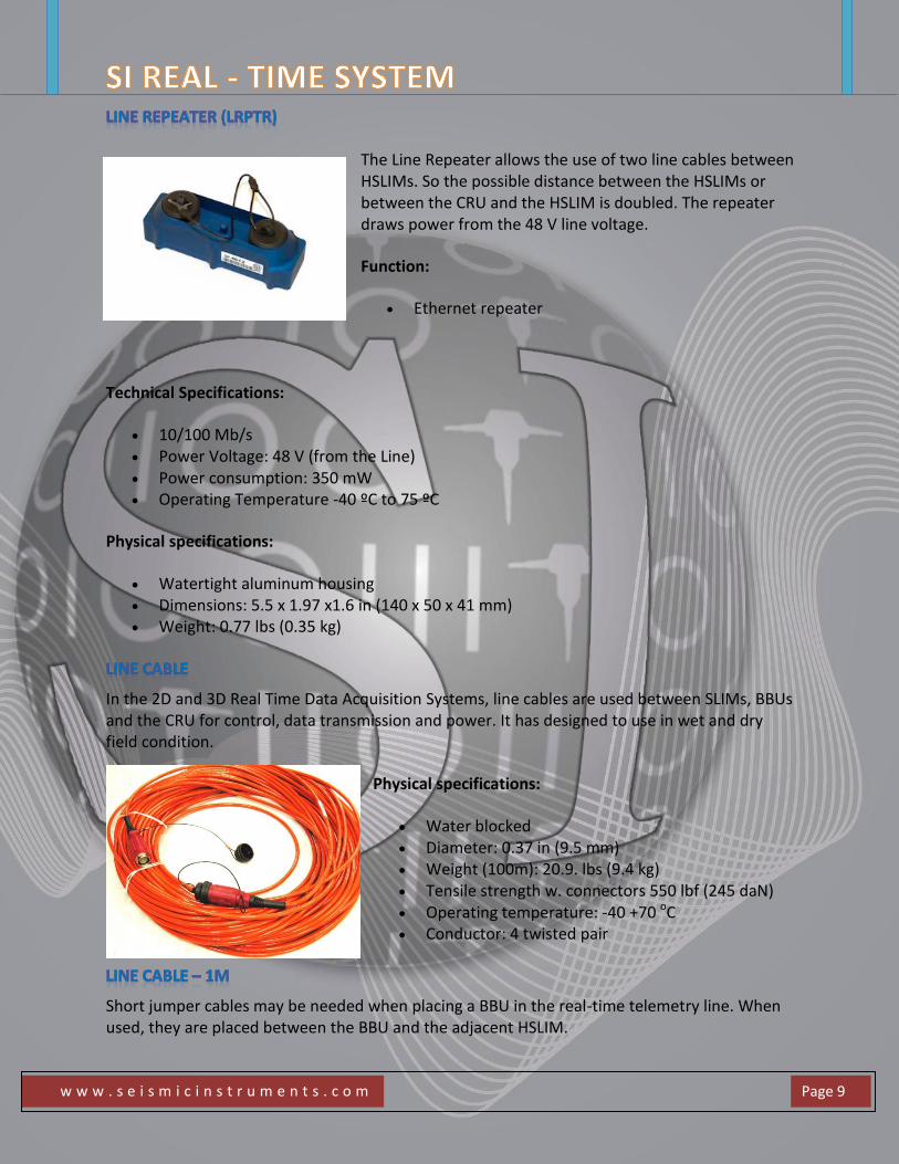
The Line Repeater allows the use of two line cables between HSLIMs. So the possible distance between the HSLIMs or between the CRU and the HSLIM is doubled. The repeater draws power from the 48 V line voltage.
Function:
Ethernet repeater
Technical Specifications:
10/100 Mb/s Power Voltage: 48 V (from the Line) Power consumption: 350 mW Operating Temperature -40 ºC to 75 ºC
Physical specifications:
Watertight aluminum housing Dimensions: 5.5 x 1.97 x1.6 in (140 x 50 x 41 mm) Weight: 0.77 lbs (0.35 kg)
In the 2D and 3D Real Time Data Acquisition Systems, line cables are used between SLIMs, BBUs and the CRU for control, data transmission and power. It has designed to use in wet and dry field condition.
Physical specifications:
Water blocked Diameter: 0.37 in (9.5 mm) Weight (100m): 20.9. lbs (9.4 kg) Tensile strength w. connectors 550 lbf (245 daN) Operating temperature: -40 +70 oC Conductor: 4 twisted pair
Short jumper cables may be needed when placing a BBU in the real-time telemetry line. When used, they are placed between the BBU and the adjacent HSLIM.
w w w . s e i s m i c i n s t r u m e n t s . c o m
Page 10
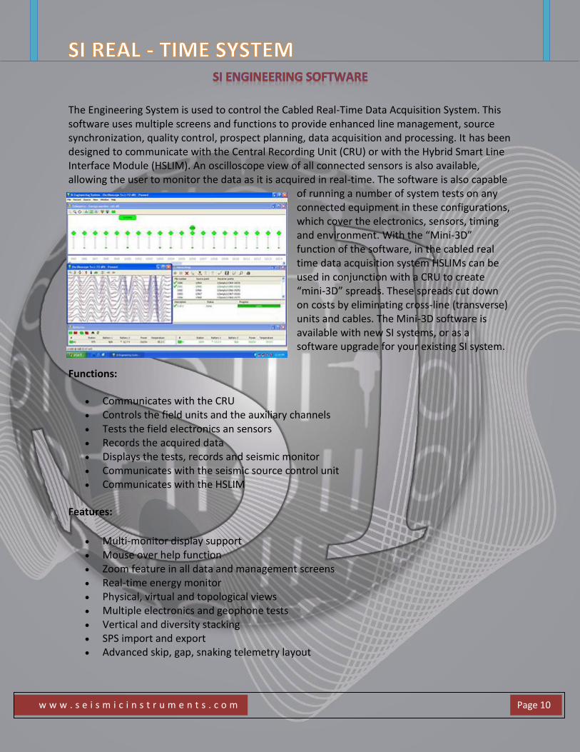
The Engineering System is used to control the Cabled Real-Time Data Acquisition System. This software uses multiple screens and functions to provide enhanced line management, source synchronization, quality control, prospect planning, data acquisition and processing. It has been designed to communicate with the Central Recording Unit (CRU) or with the Hybrid Smart Line Interface Module (HSLIM). An oscilloscope view of all connected sensors is also available, allowing the user to monitor the data as it is acquired in real-time. The software is also capable
of running a number of system tests on any connected equipment in these configurations, which cover the electronics, sensors, timing and environment. With the “Mini-3D” function of the software, in the cabled real time data acquisition system HSLIMs can be used in conjunction with a CRU to create “mini-3D” spreads. These spreads cut down on costs by eliminating cross-line (transverse) units and cables. The Mini-3D software is available with new SI systems, or as a software upgrade for your existing SI system.
Functions:
Communicates with the CRU Controls the field units and the auxiliary channels Tests the field electronics an sensors Records the acquired data Displays the tests, records and seismic monitor Communicates with the seismic source control unit Communicates with the HSLIM
Features:
Multi-monitor display support Mouse over help function Zoom feature in all data and management screens Real-time energy monitor Physical, virtual and topological views Multiple electronics and geophone tests Vertical and diversity stacking SPS import and export Advanced skip, gap, snaking telemetry layout
w w w . s e i s m i c i n s t r u m e n t s . c o m
Page 11
Seismic Instruments, Inc. 7501 North Capital of Texas Hwy Building A, Suite 150 Austin, TX 78731 United States Phone: +1 512 342-1819
General information: [email protected]
Technical Support: [email protected]