sgsn serving radio network subsystem relocation...sgsnservingradionetworksubsystem relocation...
TRANSCRIPT
SGSN Serving Radio Network SubsystemRelocation
This chapter describes the SGSN Serving Radio Network Subsystem Relocation (SRNS) feature.
• Feature Description, on page 1• How it Works, on page 2• Configuring SRNS Relocation on the SGSN, on page 37• Monitoring and Troubleshooting SRNS Relocation, on page 39
Feature DescriptionThe SRNS relocation feature facilitates connectedmode inter-RAT handovers between UTRAN (3G) networksor between UTRAN and EUTRAN (LTE) networks. The advantage of this feature is that the radio bearerestablishment occurs before the actual handover at the target.
The Gn/Gp SGSN and S4-SGSN support inter- and intra-SGSN SRNS relocation to enable:
• Handovers of an MS from one RNC to another RNC• Handovers of an MS from one RNC to an eNodeb
The S4-SGSN supports the optional setup of indirect data forwarding tunnels (IDFT) between the eNodeBand the RNC via the SGW during connected mode handovers. This allows the S4-SGSN to support connectedmode handovers between the UTRAN and E-UTRAN networks across the S3 interface. IDFT is not supportedon the SGSN across the Gn interface.
The SRNS Relocation feature is included with the base SGSN license. It does not require an additional featurelicense.
Relationships to Other FeaturesThis section describes how the SRNS Relocation feature relates to other SGSN features.
• For an SGSN operating via the Gn/Gp interfaces, a 3G service (sgsn-service) must be configured andenabled before SRNS Relocation can be configured.
• For an S4-SGSN, both a 3G service (sgsn-service) and S4-SGSN support (egtp-service)must be configuredbefore SRNS Relocation can be configured.
• If operators are using non-standard LAC ranges, then a network-global-mme-id-mgmt-db must beconfigured and associated with the sgsn-service.
SGSN Serving Radio Network Subsystem Relocation1
For detailed instructions on configuring the above, refer to the appropriate chapters in this guide.
How it Works
SRNS Relocation on the SGSN (Gn/Gp)On the Gn/Gp SGSN, the SRNS relocation feature is triggered by subscribers (MS/UE) moving from oneRNS to another. If the originating RNS and destination RNS are connected to the same SGSN but are indifferent routing areas, the behavior triggers an intra-SGSN Routing Area Update (RAU). If the RNSs areconnected to different SGSNs, the relocation is followed by an inter-SGSN RAU.
The following table describes the interface selection logic for the various types of SRNS relocation that canoccur when the interface used for a subscriber is Gn for PDP contexts. Note that the Gn/Gp SGSN SRNSrelocation selection logic is applicable in the following instances:
• An S4-SGSN is configured (both the S4 license and EGTP service are available), but a given subscriberuses the Gn interface for PDP contexts.
• Only the Gn/Gp interfaces are utilized on the SGSN. S4 support is not configured.
Table 1: Interface Selection Logic for SRNS Relocation on the SGSN Gn/Gp
InterfaceChosen
Interface IPProvided byDNS
DNS QueryType
Peer TypeLAC MSB SetLACConfiguredas MMEGroup ID
Target TypeSent in Rel.Req.
RNC ReleaseCompliance
SI.No
GnGnWhen the Gninterface isused, thesystem mapsthe eNB IDto the RNCID asfollows: TheMSB 12 bitsof the 20 biteNB ID ismapped toRNC ID.DSN Aquery withRNC IDFQDN issent and Gnaddress isselected.
MMEIrrelevantNotApplicable
eNodeBR8+1
SGSN Serving Radio Network Subsystem Relocation2
SGSN Serving Radio Network Subsystem RelocationHow it Works
InterfaceChosen
Interface IPProvided byDNS
DNS QueryType
Peer TypeLAC MSB SetLACConfiguredas MMEGroup ID
Target TypeSent in Rel.Req.
RNC ReleaseCompliance
SI.No
GnGnDNS AQuery withRNC IDFQDN
SGSNIrrelevantNotApplicable
RNCR8+2
GnGnDNS AQuery withRNC IDFQDN
It is notimportant toa Gn SGSNif the peer isan MME oran SGSN.For a GnSGSN, a peerMME istreated justlike anSGSN
IrrelevantIrrelevantRNCPre R83
SGSN (Gn/Gp) SRNS Relocation Call Flow DiagramsThis section provides call flow diagrams and process descriptions for the following SGSN Gn/Gp SRNSRelocation scenarios:
• Inter-SGSN (Gn/Gp) SRNS Relocation Call Flow• Intra-SGSN (Gn/Gp) SRNS Relocation Call Flow
The Inter-SGSN (Gn/Gp) SRNS Relocation procedure is illustrated in the following diagram.
SGSN Serving Radio Network Subsystem Relocation3
SGSN Serving Radio Network Subsystem RelocationSGSN (Gn/Gp) SRNS Relocation Call Flow Diagrams
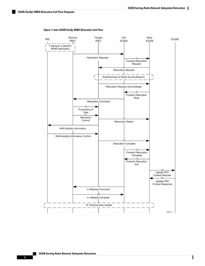
Figure 1: Inter-SGSN Gn/Gp SRNS Relocation Call Flow
SGSN Serving Radio Network Subsystem Relocation4
SGSN Serving Radio Network Subsystem RelocationSGSN (Gn/Gp) SRNS Relocation Call Flow Diagrams
Table 2: Inter-SGSN (Gn/Gp) SRNS Relocation Process Description
DescriptionStep
The source SRNC decides to perform/initiate SRNSrelocation.
1
The source SRNC sends a Relocation Requiredmessage (Relocation Type, Cause, Source ID, TargetID, Source RNC to target RNC transparent container)to the old SGSN.
2
The old SGSN determines from the Target ID that aninter-SGSN SRNS relocation is required. A DNS Aquery is performed for the target RNC ID FQDN toobtain the target SGSN IP address. The old SGSNthen sends a Forward Relocation Request to the newSGSN.
3
The new SGSN sends a Relocation Request messageto the new RNC. At this point, radio access bearershave been established.
4
The new RNC sends a Relocation Request Responsemessage to the new SGSN.
5
When resources for the transmission of user databetween the new RNC and the new SGSN have beenallocated and the new SGSN is ready for relocationof SRNS, the Forward Relocation Response message(Cause, RANAPCause, and RAB Setup Information)is sent from the new SGSN to the old SGSN.
6
The old SGSN continues the relocation of SRNS bysending a Relocation Command message to the oldRNC. The old SGSN sends the RAB setup informationreceived in the Forward Relocation Response in aRelocation Command to the old RNC. This enablesthe old RNC to establish a data path with new RNCso that it can forward the data packets.
7
The old SRNC may, according to the QoS profile,begin the forwarding of data for the RABs to besubject for data forwarding.
8
Before sending the Relocation Commit the uplink anddownlink data transfer in the source, the SRNC shallbe suspended for RABs, which require a deliveryorder. The source RNC starts the data-forwardingtimer. When the old SRNC is ready, the old SRNCtriggers the execution of relocation of SRNS bysending a Relocation Commit message (SRNSContexts) to the new RNC over the Iur interface.
9
SGSN Serving Radio Network Subsystem Relocation5
SGSN Serving Radio Network Subsystem RelocationSGSN (Gn/Gp) SRNS Relocation Call Flow Diagrams
DescriptionStep
The target RNC sends a Relocation Detect messageto the new SGSN when the relocation executiontrigger is received.
10
The new RNC sends a RAN Mobility Informationmessage. This message contains UE informationelements and CN information elements.
11
When the new SRNC receives the RAN MobilityInformation Confirm message, i.e. the new SRNCID+ S-RNTI are successfully exchanged with the MSby the radio protocols, the target SRNC initiates theRelocation Complete procedure by sending theRelocation Complete message to the new SGSN.
12
The old SGSN sends a Forward Relocation Completemessage.
13
The old SGSN sends a Forward RelocationAcknowledgement to the new SGSN. to signal to thenew SGSN the completion of the SRNS relocationprocedure.
14
Upon receipt of the Relocation Complete message,the CN switches the user plane from the old RNC tothe new SRNC. The new SGSN sends Update PDPContext Request messages to the GGSN.
15
The GGSN sends Update PDP Context Responsemessages to the new SGSN.
16
The old SGSN sends an Iu ReleaseCommandmessageto the old RNC.
17
The old RNC sends an Iu Release Complete messageto the old SGSN.
18
After the MS has finished the RNTI reallocationprocedure, and if the new Routing Area Identificationis different from the old one, the MS initiates theRouting Area Update procedure.
19
The intra-SGSN Gn/Gp SRNS Relocation procedure is illustrated in the following figure.
SGSN Serving Radio Network Subsystem Relocation6
SGSN Serving Radio Network Subsystem RelocationSGSN (Gn/Gp) SRNS Relocation Call Flow Diagrams
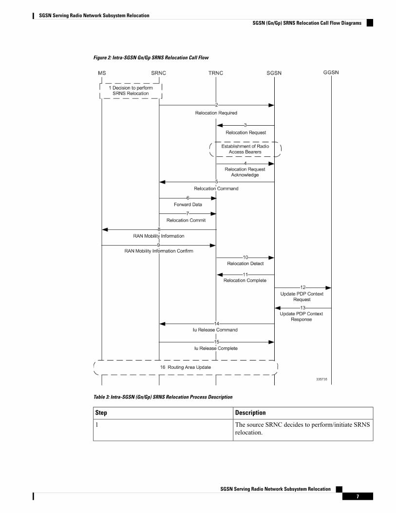
Figure 2: Intra-SGSN Gn/Gp SRNS Relocation Call Flow
Table 3: Intra-SGSN (Gn/Gp) SRNS Relocation Process Description
DescriptionStep
The source SRNC decides to perform/initiate SRNSrelocation.
1
SGSN Serving Radio Network Subsystem Relocation7
SGSN Serving Radio Network Subsystem RelocationSGSN (Gn/Gp) SRNS Relocation Call Flow Diagrams
DescriptionStep
The old RNC sends a Relocation Required messageto the SGSN.
2
The SGSN sends a Relocation Request message tothe newRNC. At this point, radio access bearers havebeen established.
3
The new RNC sends a Relocation RequestAcknowledgement message to the SGSN.
4
The SGSN sends a Relocation Command to the oldRNC and the UE is detached from the old RNC andattached to the new RNC.
5
The old SRNC may, according to the QoS profile,begin the forwarding of data for the RABs to besubject for data forwarding.
6
Before sending the Relocation Commit the uplink anddownlink data transfer in the source, the SRNC shallbe suspended for RABs, which require a deliveryorder. The source RNC starts the data-forwardingtimer. When the old SRNC is ready, the old SRNCtriggers the execution of relocation of SRNS bysending a Relocation Commit message (SRNSContexts) to the new RNC over the Iur interface.
7
The new RNC sends a RAN Mobility Informationmessage. This message contains UE informationelements and CN information elements.
8
When the new SRNC receives the RAN MobilityInformation Confirm message, i.e. the new SRNCID+ S-RNTI are successfully exchanged with the MSby the radio protocols, the target SRNC initiates theRelocation Complete procedure by sending theRelocation Commit message to the new SGSN.
9
The new RNC sends a Relocation Detect message tothe SGSN.
10
The SGSN sends a Relocation Complete message tothe new RNC.
11
If Direct Tunnel was established during intra-SGSNSRNS relocation, the SGSN sends Update PDPContext Request messages to the GGSN.
12
If Direct Tunnel was established during intra-SGSNSRNS relocation, the SGSN sends Update PDPContext Response messages to the GGSN.
13
SGSN Serving Radio Network Subsystem Relocation8
SGSN Serving Radio Network Subsystem RelocationSGSN (Gn/Gp) SRNS Relocation Call Flow Diagrams

DescriptionStep
The SGSN sends an Iu Release Command to the oldRNC.
14
The old RNC releases the Iu connection and sends aRelease Complete message to the SGSN.
15
After the MS has finished the RNTI reallocationprocedure, and if the new Routing Area Identificationis different from the old one, the MS initiates theRouting Area Update procedure.
16
SRNS Relocation on the S4-SGSNOn the S4-SGSN, the SRNS relocation feature is triggered by subscribers (MS/UE) moving between aneNodeB and an RNC or between two RNCs.
If the originating and destination nodes are connected to the same S4-SGSN but are in different routing areas,the behavior triggers an intra-SGSN Routing Area Update (RAU).
If the nodes are connected to different S4-SGSNs, the relocation is followed by an inter-SGSN RAU. ThisRAU occurs over a RANAP direct transfer. As a result, it does not trigger Context Request/ContextResponse/Context Ack procedures with the old SGSN/MME. These procedures are otherwise performedduring a normal SGSN RAU.
The GTPv2 protocol is used for SRNS relocation between two RNCs and between an eNodeB and an RNC.
In addition to supporting Inter-SGSN SRNS relocation across the Gn interface, the S4-SGSN supports SRNSrelocation for the following scenarios across the S3 (S4-SGSN to MME) and S16 (S4-SGSN to S4-SGSN)interfaces:
• Inter-SGSN SRNS relocation over the S16 interface• UTRAN-to-E-UTRAN connected mode Inter-RAT handover over the S3 interface• E-UTRAN-to-UTRAN connected mode Inter-RAT handover over the S3 interface
As part of the SRNS relocation feature implementation on the S4-SGSN, the SGSN application also supportsthe gtpv2 (egtp) protocol for:
• Inter-SGSN SRNS relocations over the S16 interface• MME - SGSN SRNS relocations over the S3 interface
S4-SGSN SRNS relocation interface selection logic is based on the following assumptions:
• If the egtp-service is configured, it is assumed the network is EPC capable and therefore must require aDNS SNAPTR.
• If the egtp-service is configured on the S4-SGSN, then for outbound SRNS relocation, the system alwaysperforms a DNS SNAPTR as follows:
• x-S16 if the peer detected is another S4-GSN, or x-S3 if the peer detected is an MME (based onwhether the target is an eNodeB/the MSB of the target LAC being 1, or, if a local MME group IDis configured).
•
• x-gn if a local configuration for a peer SGSN orMME exists with a Gn address, or, if DNS SNAPTRreturned a GN address.
If both DNS queries fail, the system rejects the SRNS relocation.
SGSN Serving Radio Network Subsystem Relocation9
SGSN Serving Radio Network Subsystem RelocationSRNS Relocation on the S4-SGSN
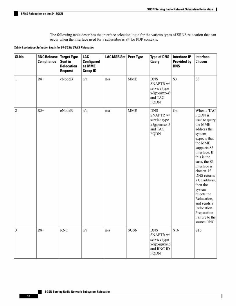
The following table describes the interface selection logic for the various types of SRNS relocation that canoccur when the interface used for a subscriber is S4 for PDP contexts.
Table 4: Interface Selection Logic for S4-SGSN SRNS Relocation
InterfaceChosen
Interface IPProvided byDNS
Type of DNSQuery
Peer TypeLAC MSB SetLACConfiguredas MMEGroup ID
Target TypeSent inRelocationRequest
RNC ReleaseCompliance
SI.No
S3S3DNSSNAPTR w/service typex-3gpp-mme:x-s3and TACFQDN
MMEn/an/aeNodeBR8+1
When a TACFQDN isused to querythe MMEaddress thesystemexpects thatthe MMEsupports S3interface. Ifthis is thecase, the S3interface ischosen. IfDNS returnsa Gn address,then thesystemrejects theRelocation,and sends aRelocationPreparationFailure to thesource RNC.
GnDNSSNAPTR w/service typex-3gpp-mme:x-s3and TACFQDN
MMEn/an/aeNodeBR8+2
S16S16DNSSNAPTR w/service typex-3gpp-sgsn:x-s16and RNC IDFQDN
SGSNn/an/aRNCR8+3
SGSN Serving Radio Network Subsystem Relocation10
SGSN Serving Radio Network Subsystem RelocationSRNS Relocation on the S4-SGSN
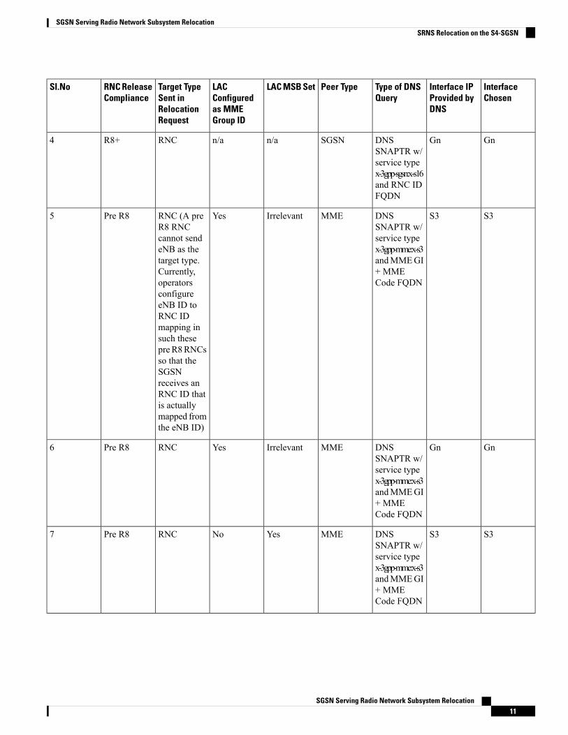
InterfaceChosen
Interface IPProvided byDNS
Type of DNSQuery
Peer TypeLAC MSB SetLACConfiguredas MMEGroup ID
Target TypeSent inRelocationRequest
RNC ReleaseCompliance
SI.No
GnGnDNSSNAPTR w/service typex-3gpp-sgsn:x-s16and RNC IDFQDN
SGSNn/an/aRNCR8+4
S3S3DNSSNAPTR w/service typex-3gpp-mme:x-s3andMMEGI+ MMECode FQDN
MMEIrrelevantYesRNC (A preR8 RNCcannot sendeNB as thetarget type.Currently,operatorsconfigureeNB ID toRNC IDmapping insuch thesepre R8RNCsso that theSGSNreceives anRNC ID thatis actuallymapped fromthe eNB ID)
Pre R85
GnGnDNSSNAPTR w/service typex-3gpp-mme:x-s3andMMEGI+ MMECode FQDN
MMEIrrelevantYesRNCPre R86
S3S3DNSSNAPTR w/service typex-3gpp-mme:x-s3andMMEGI+ MMECode FQDN
MMEYesNoRNCPre R87
SGSN Serving Radio Network Subsystem Relocation11
SGSN Serving Radio Network Subsystem RelocationSRNS Relocation on the S4-SGSN
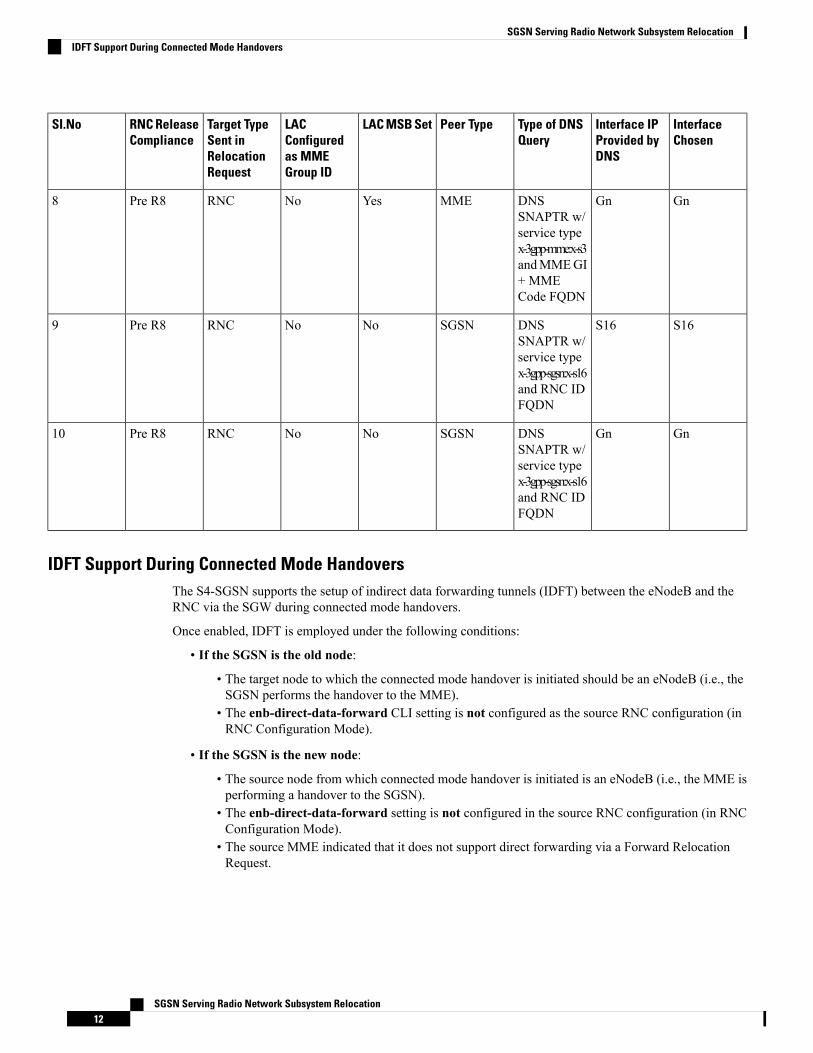
InterfaceChosen
Interface IPProvided byDNS
Type of DNSQuery
Peer TypeLAC MSB SetLACConfiguredas MMEGroup ID
Target TypeSent inRelocationRequest
RNC ReleaseCompliance
SI.No
GnGnDNSSNAPTR w/service typex-3gpp-mme:x-s3andMMEGI+ MMECode FQDN
MMEYesNoRNCPre R88
S16S16DNSSNAPTR w/service typex-3gpp-sgsn:x-s16and RNC IDFQDN
SGSNNoNoRNCPre R89
GnGnDNSSNAPTR w/service typex-3gpp-sgsn:x-s16and RNC IDFQDN
SGSNNoNoRNCPre R810
IDFT Support During Connected Mode HandoversThe S4-SGSN supports the setup of indirect data forwarding tunnels (IDFT) between the eNodeB and theRNC via the SGW during connected mode handovers.
Once enabled, IDFT is employed under the following conditions:
• If the SGSN is the old node:
• The target node to which the connected mode handover is initiated should be an eNodeB (i.e., theSGSN performs the handover to the MME).
• The enb-direct-data-forward CLI setting is not configured as the source RNC configuration (inRNC Configuration Mode).
• If the SGSN is the new node:
• The source node from which connected mode handover is initiated is an eNodeB (i.e., the MME isperforming a handover to the SGSN).
• The enb-direct-data-forward setting is not configured in the source RNC configuration (in RNCConfiguration Mode).
• The source MME indicated that it does not support direct forwarding via a Forward RelocationRequest.
SGSN Serving Radio Network Subsystem Relocation12
SGSN Serving Radio Network Subsystem RelocationIDFT Support During Connected Mode Handovers
If the target SGSN did not relocate to a new SGW, IDFT setup does not apply at the SGSN. The target SGSNsets up an indirect data forwarding tunnel with the SGW only if the SGW is relocated. If the SGW is notrelocated, then it is the source MME that sets up the indirect data forwarding tunnel between source theeNodeB and target RNC through the SGW.
Important
The following diagram illustrates the interface selection logic for S4-SGSN connected mode handovers.
SGSN Serving Radio Network Subsystem Relocation13
SGSN Serving Radio Network Subsystem RelocationIDFT Support During Connected Mode Handovers
Figure 3: Interface Selection Logic for S4-SGSN SRNS Connected Mode Handovers
S4-SGSN SRNS Relocation Call Flow DiagramsThis section provides call flow diagrams for the following S4-SGSN SRNS relocation scenarios:
SGSN Serving Radio Network Subsystem Relocation14
SGSN Serving Radio Network Subsystem RelocationS4-SGSN SRNS Relocation Call Flow Diagrams
• Inter-S4-SGSN SRNS Relocation without SGW Relocation• Inter-S4-SGSN Relocation with SGW Relocation• Intra-S4-SGSN SRNS Relocation without SGW Relocation• Inter-S4-SGSN Relocation with SGW Relocation• S4-SGSN E-UTRAN to UTRAN Connected Mode Handover without SGW Relocation• S4-SGSN UTRAN to E-UTRAN Connected Mode Handover with SGW Relocation Call Flow• S4-SGSN Inter-SGSN SRNS Relocation with Hard Handover and SGW Relocation
SGSN Serving Radio Network Subsystem Relocation15
SGSN Serving Radio Network Subsystem RelocationS4-SGSN SRNS Relocation Call Flow Diagrams
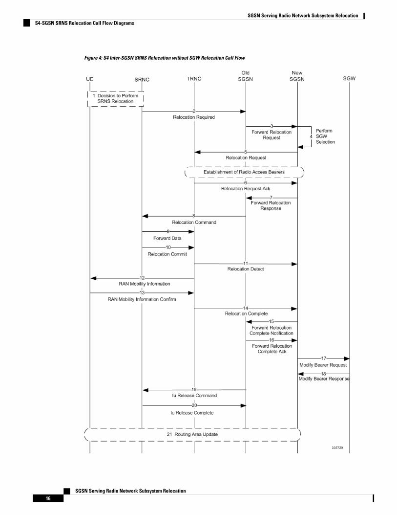
Figure 4: S4 Inter-SGSN SRNS Relocation without SGW Relocation Call Flow
SGSN Serving Radio Network Subsystem Relocation16
SGSN Serving Radio Network Subsystem RelocationS4-SGSN SRNS Relocation Call Flow Diagrams

Table 5: Inter-S4-SGSN SRNS Relocation without SGW Relocation Process Description
DescriptionStep
The decision is made to perform SRNS relocation.1
The old RNC sends a Relocation Required messageto the old SGSN.
2
The old SGSN sends a Forward Relocation Requestto the new SGSN.
3
The new SGSN performs SGW selection, but doesnot select a new SGW, as the subscriber is anchoredat the same SGW as it was previously.
4
The new SGSN sends a Relocation Request messageto the new RNC. At this point, Radio Access Bearersare established.
5
The new RNC sends a Relocation RequestAcknowledgment to the new SGSN.
6
The new SGSN sends a Forward Relocation Responseto the old SGSN. In this message, the old SGSN sendsthe RAB context information of the new RNC, whichwas obtained from the Relocation Request Ackmessage.
7
The old SGSN sends a Relocation Command to theold RNC. The old SGSN sends the new RNC RABcontext information to the old RNC in the RelocationCommand message so that old RNC can forwardpackets to the new RNC.
8
The old SRNC may, according to the QoS profile,begin the forwarding of data for the RABs to besubject for data forwarding.
9
Before sending the Relocation Commit the uplink anddownlink data transfer in the source, the SRNC shallbe suspended for RABs, which require a deliveryorder. The source RNC starts the data-forwardingtimer. When the old SRNC is ready, the old SRNCtriggers the execution of relocation of SRNS bysending a Relocation Commit message (SRNSContexts) to the new RNC over the Iur interface.
10
The new RNC sends a Relocation Detect message tothe new SGSN.
11
The new RNC sends a RAN Mobility Informationmessage. This message contains UE informationelements and CN information elements.
12
SGSN Serving Radio Network Subsystem Relocation17
SGSN Serving Radio Network Subsystem RelocationS4-SGSN SRNS Relocation Call Flow Diagrams
DescriptionStep
When the new SRNC receives the RAN MobilityInformation Confirm message, i.e. the new SRNCID+ S-RNTI are successfully exchanged with the MSby the radio protocols, the target SRNC initiates theRelocation Complete procedure by sending theRelocation Commit message to the new SGSN.
13
The new RNC sends a Relocation Complete messageto the new SGSN.
14
The new SGSN sends a Forward RelocationNotification Complete message to the old SGSN.
15
The new SGSN sends a Forward Relocation CompleteAck message to the old SGSN.
16
The new SGSN sends aModify Bearer Request to theSGW.
17
The SGW sends a Modify Bearer Response to thenew SGSN.
18
The old SGSN sends an Iu ReleaseCommandmessageto the old RNC.
19
The old RNC sends an Iu Release Complete messageto the old SGSN.
20
After the MS has finished the RNTI reallocationprocedure, and if the new Routing Area Identificationis different from the old one, the MS initiates theRouting Area Update procedure.
21
SGSN Serving Radio Network Subsystem Relocation18
SGSN Serving Radio Network Subsystem RelocationS4-SGSN SRNS Relocation Call Flow Diagrams
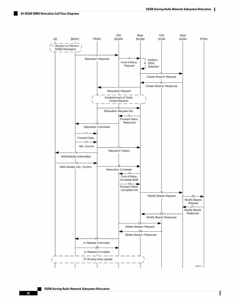
Figure 5: Inter-S4-SGSN Relocation with SGW Relocation
SGSN Serving Radio Network Subsystem Relocation19
SGSN Serving Radio Network Subsystem RelocationS4-SGSN SRNS Relocation Call Flow Diagrams
SGSN Serving Radio Network Subsystem Relocation20
SGSN Serving Radio Network Subsystem RelocationS4-SGSN SRNS Relocation Call Flow Diagrams
Table 6: Inter-S4-SGSN Relocation with SGW Relocation Process Description
DescriptionStep
The decision is made to perform SRNS relocation.1
The old RNC informs the old SGSN that relocationis required by sending a Relocation Requiredmessage.
2
The old SGSN initiates the relocation resourceallocation procedure by sending a Forward RelocationRequest message to the new SGSN.
3
The new SGSN performs SGW selection.4
The new SGSN sends a Create Session Request to thenew SGW with Indication Flags - OperationsIndication bit = 0. The new SGW will not send aModify Bearer Request to the PGW at this time.
5
The new SGW sends a Create Session Response tothe new SGSN.
6
The new SGSN sends a Relocation Request to thenew RNC. At this point radio access bearers are setup between the new RNC and the new SGSN.
7
The new RNC sends a Relocation RequestAcknowledge message to the new SGSN.
8
The new SGSN sends a Forward Relocation Responsemessage to the old SGSN. In this message, the oldSGSN sends the RAB context information of the newRNC, which was obtained from Relocation RequestAcknowledge message.
9
The old SGSN sends a Relocation Command to theold RNC. The old SGSN sends the new RNC RABcontext information to the old RNC in the RelocationCommand so that the old RNC can forward packetsto the new RNC.
10
The old SRNC may, according to the QoS profile,begin the forwarding of data for the RABs to besubject for data forwarding.
11
Before sending the Relocation Commit the uplink anddownlink data transfer in the source, the SRNC shallbe suspended for RABs, which require a deliveryorder. The source RNC starts the data-forwardingtimer. When the old SRNC is ready, the old SRNCtriggers the execution of relocation of SRNS bysending a Relocation Commit message (SRNSContexts) to the new RNC over the Iur interface.
12
SGSN Serving Radio Network Subsystem Relocation21
SGSN Serving Radio Network Subsystem RelocationS4-SGSN SRNS Relocation Call Flow Diagrams
DescriptionStep
The new RNC sends a Relocation Detect message tothe new SGSN.
13
The new RNC sends a RAN Mobility Informationmessage. This message contains UE informationelements and CN information elements.
14
When the new SRNC receives the RAN MobilityInformation Confirm message, i.e. the new SRNCID+ S-RNTI are successfully exchanged with the MSby the radio protocols, the target SRNC initiates theRelocation Complete procedure by sending theRelocation Commit message to the new SGSN.
15
The new RNC sends a Relocation Complete messageto the new SGSN.
16
The new SGSN sends a Forward Relocation CompleteNotification message to the old SGSN.
17
The old SGSN sends a Forward Relocation CompleteAck message to the new SGSN.
18
The new SGSN sends a Modify Bearer Requestmessage to the new SGW.
19
The SGW sends a Modify Bearer Request messageto the PGW.
20
The PGW sends a Modify Bearer Response to thenew SGW.
21
The SGW sends a Modify Bearer Response to thenew SGSN.
22
The old SGSN sends a Delete Session Request to theold SGW.
23
The old SGW sends a Delete Session Response to theold SGSN.
24
The old SGSN sends an Iu ReleaseCommandmessageto the old RNC.
25
The old RNC sends an Iu Release Complete messageto the old SGSN.
26
After the MS has finished the RNTI reallocationprocedure, and if the new Routing Area Identificationis different from the old one, the MS initiates theRouting Area Update procedure.
27
SGSN Serving Radio Network Subsystem Relocation22
SGSN Serving Radio Network Subsystem RelocationS4-SGSN SRNS Relocation Call Flow Diagrams
Figure 6: Intra-S4-SGSN SRNS Relocation without SGW Relocation
Table 7: Intra-S4-SGSN SRNS Relocation without SGW Relocation Process Description
DescriptionStep
The decision is made to perform SRNS relocation.1
The old RNC sends a Relocation Required messageto the SGSN.
2
The SGSN performs SGW selection, but does notselect a new SGW, as the subscriber is anchored atthe same SGW as it was previously.
3
SGSN Serving Radio Network Subsystem Relocation23
SGSN Serving Radio Network Subsystem RelocationS4-SGSN SRNS Relocation Call Flow Diagrams
DescriptionStep
The SGSN sends a Relocation Request message tothe newRNC. At this point, radio access bearers havebeen established.
4
The new RNC sends a Relocation RequestAcknowledgment message to the SGSN.
5
The SGSN sends a Relocation Command to the oldRNC and the UE is detached from the old RNC andattached to the new RNC.
6
The old SRNC may, according to the QoS profile,begin the forwarding of data for the RABs to besubject for data forwarding.
7
Before sending the Relocation Commit the uplink anddownlink data transfer in the source, the SRNC shallbe suspended for RABs, which require a deliveryorder. The source RNC starts the data-forwardingtimer. When the old SRNC is ready, the old SRNCtriggers the execution of relocation of SRNS bysending a Relocation Commit message (SRNSContexts) to the new RNC over the Iur interface.
8
The new RNC sends a RAN Mobility Informationmessage. This message contains UE informationelements and CN information elements.
9
When the new SRNC receives the RAN MobilityInformation Confirm message, i.e. the new SRNCID+ S-RNTI are successfully exchanged with the MSby the radio protocols, the target SRNC initiates theRelocation Complete procedure by sending theRelocation Commit message to the new SGSN.
10
The new RNC sends a Relocation Detect message tothe SGSN.
11
The SGSN sends a Relocation Complete message tothe new RNC.
12
The SGSN sends an Iu Release Command to the oldRNC.
13
The old RNC releases the Iu connection and sends aRelease Complete message to the SGSN.
14
After the MS has finished the RNTI reallocationprocedure, and if the new Routing Area Identificationis different from the old one, the MS initiates theRouting Area Update procedure.
15
SGSN Serving Radio Network Subsystem Relocation24
SGSN Serving Radio Network Subsystem RelocationS4-SGSN SRNS Relocation Call Flow Diagrams
Figure 7: Intra-S4-SGSN Relocation with SGW Relocation
SGSN Serving Radio Network Subsystem Relocation25
SGSN Serving Radio Network Subsystem RelocationS4-SGSN SRNS Relocation Call Flow Diagrams
Table 8: Intra-S4-SGSN Relocation with SGW Relocation Process Description
DescriptionStep
The decision is made to perform SRNS relocation.1
The old RNC sends a Relocation Required messageto the SGSN.
2
The SGSN selects a new SGW for the UE.3
The SGSN sends a Create Session Request to the newSGW with Indication Flags - Operations Indicationbit=0. The new SGW does not send a Modify BeaterRequest to the PGW at this time.
4
The new SGW sends a Create Session Response tothe SGSN.
5
The SGSN sends a Relocation Request to the newRNC. At this point, radio access bearers have beenestablished.
6
The new RNC sends a Relocation RequestAcknowledge message to the SGSN.
7
The SGSN sends a Relocation Command to the oldRNC.
8
The new RNC sends a RAN Mobility Informationmessage. This message contains UE informationelements and CN information elements.
9
When the new SRNC receives the RAN MobilityInformation Confirm message, i.e. the new SRNCID+ S-RNTI are successfully exchanged with the MSby the radio protocols, the target SRNC initiates theRelocation Complete procedure by sending theRelocation Commit message to the new SGSN.
10
The new RNC sends a RAN Mobility Informationmessage. This message contains UE informationelements and CN information elements.
11
When the new SRNC receives the RAN MobilityInformation Confirm message, i.e. the new SRNCID+ S-RNTI are successfully exchanged with the MSby the radio protocols, the target SRNC initiates theRelocation Complete procedure by sending theRelocation Commit message to the new SGSN.
12
The new RNC sends a Relocation Detect message tothe SGSN.
13
SGSN Serving Radio Network Subsystem Relocation26
SGSN Serving Radio Network Subsystem RelocationS4-SGSN SRNS Relocation Call Flow Diagrams
DescriptionStep
The new RNC sends a Relocation Complete messageto the SGSN.
14
The SGSN sends a Modify Bearer Request messageto the new SGW.
15
The new SGW sends a Modify Bearer Request to thePGW.
16
The PGW sends a Modify Bearer Response to thenew SGW.
17
The new SGW sends a Modify Bearer Response tothe SGSN.
18
The SGSN sends a Delete Session Request to the oldSGW.
19
The old SGW sends a Delete Session Response to theSGSN.
20
The SGSN sends an Iu Release Command to the oldRNC.
21
The old RNC sends an Iu Release Complete messageto the SGSN.
22
After the MS has finished the RNTI reallocationprocedure, and if the new Routing Area Identificationis different from the old one, the MS initiates theRouting Area Update procedure.
23
SGSN Serving Radio Network Subsystem Relocation27
SGSN Serving Radio Network Subsystem RelocationS4-SGSN SRNS Relocation Call Flow Diagrams
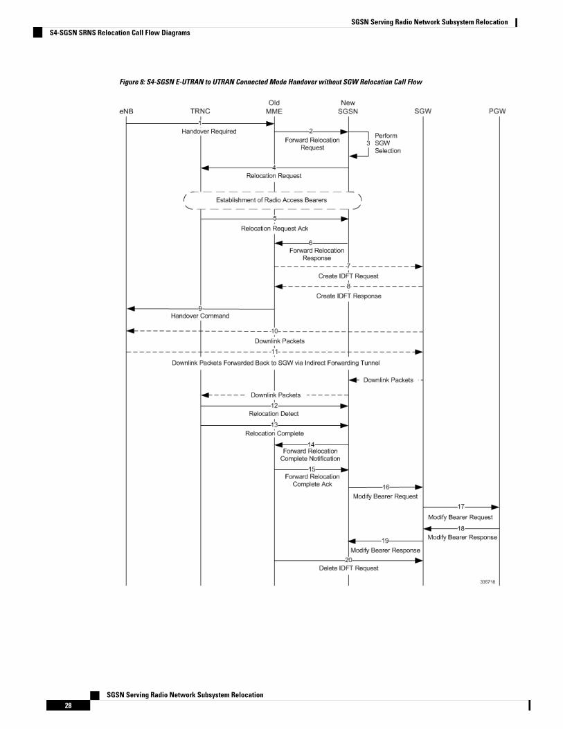
Figure 8: S4-SGSN E-UTRAN to UTRAN Connected Mode Handover without SGW Relocation Call Flow
SGSN Serving Radio Network Subsystem Relocation28
SGSN Serving Radio Network Subsystem RelocationS4-SGSN SRNS Relocation Call Flow Diagrams
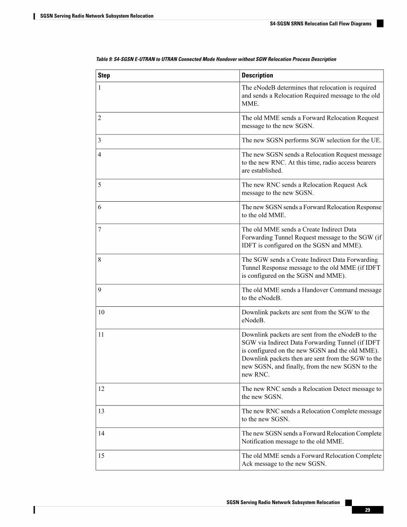
Table 9: S4-SGSN E-UTRAN to UTRAN Connected Mode Handover without SGW Relocation Process Description
DescriptionStep
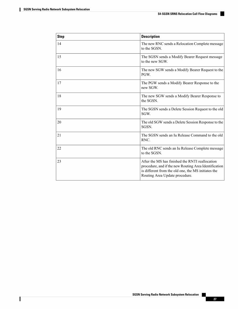
The eNodeB determines that relocation is requiredand sends a Relocation Required message to the oldMME.
1
The old MME sends a Forward Relocation Requestmessage to the new SGSN.
2
The new SGSN performs SGW selection for the UE.3
The new SGSN sends a Relocation Request messageto the new RNC. At this time, radio access bearersare established.
4
The new RNC sends a Relocation Request Ackmessage to the new SGSN.
5
The new SGSN sends a Forward Relocation Responseto the old MME.
6
The old MME sends a Create Indirect DataForwarding Tunnel Request message to the SGW (ifIDFT is configured on the SGSN and MME).
7
The SGW sends a Create Indirect Data ForwardingTunnel Response message to the old MME (if IDFTis configured on the SGSN and MME).
8
The old MME sends a Handover Command messageto the eNodeB.
9
Downlink packets are sent from the SGW to theeNodeB.
10
Downlink packets are sent from the eNodeB to theSGW via Indirect Data Forwarding Tunnel (if IDFTis configured on the new SGSN and the old MME).Downlink packets then are sent from the SGW to thenew SGSN, and finally, from the new SGSN to thenew RNC.
11
The new RNC sends a Relocation Detect message tothe new SGSN.
12
The new RNC sends a Relocation Complete messageto the new SGSN.
13
The new SGSN sends a Forward Relocation CompleteNotification message to the old MME.
14
The old MME sends a Forward Relocation CompleteAck message to the new SGSN.
15
SGSN Serving Radio Network Subsystem Relocation29
SGSN Serving Radio Network Subsystem RelocationS4-SGSN SRNS Relocation Call Flow Diagrams
DescriptionStep
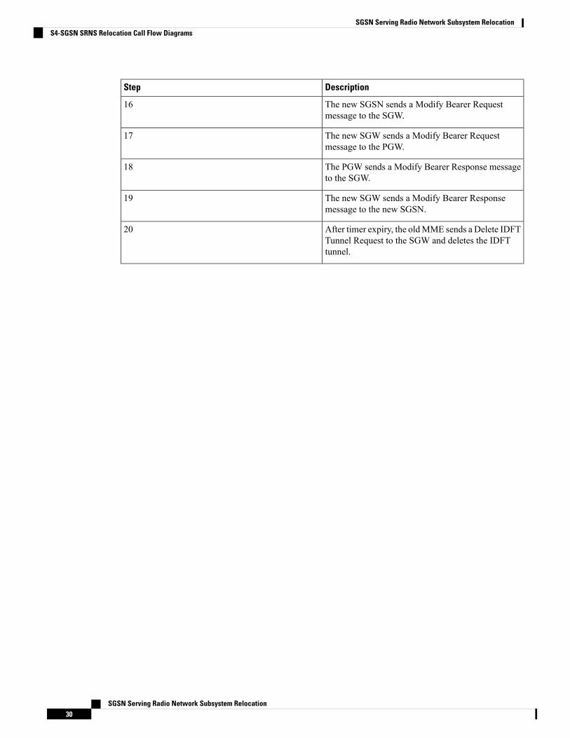
The new SGSN sends a Modify Bearer Requestmessage to the SGW.
16
The new SGW sends a Modify Bearer Requestmessage to the PGW.
17
The PGW sends a Modify Bearer Response messageto the SGW.
18
The new SGW sends a Modify Bearer Responsemessage to the new SGSN.
19
After timer expiry, the oldMME sends a Delete IDFTTunnel Request to the SGW and deletes the IDFTtunnel.
20
SGSN Serving Radio Network Subsystem Relocation30
SGSN Serving Radio Network Subsystem RelocationS4-SGSN SRNS Relocation Call Flow Diagrams
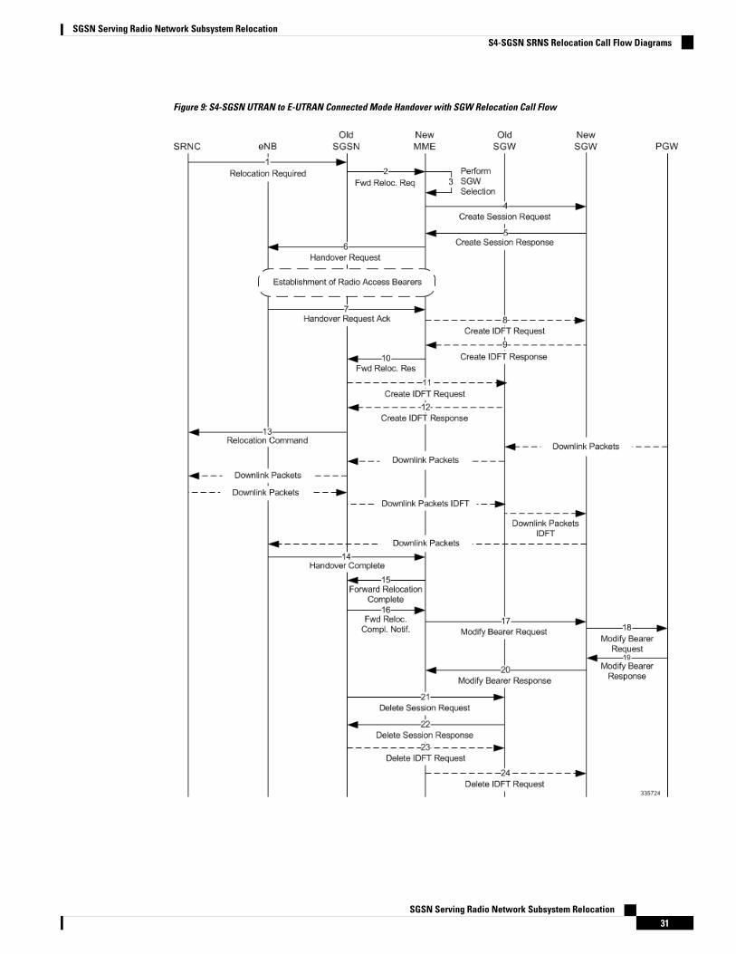
Figure 9: S4-SGSN UTRAN to E-UTRAN Connected Mode Handover with SGW Relocation Call Flow
SGSN Serving Radio Network Subsystem Relocation31
SGSN Serving Radio Network Subsystem RelocationS4-SGSN SRNS Relocation Call Flow Diagrams
Table 10: S4-SGSN UTRAN to E-UTRAN Connected Mode Handover with SGW Relocation Process Description
DescriptionStep
The old RNC determines that relocation is requiredfor a UE and sends a Relocation Required messageto the old SGSN.
1
The old SGSN sends a Forward Relocation Requestmessage to the new MME.
2
The newMME performs the selection of a new SGW.3
The new MME sends a Create Session Requestmessage to the new SGW.
4
The new SGW sends a Create Session Response tothe new MME.
5
The new MME sends a Handover Request messageto the eNobeB. At this point radio access bearers areestablished.
6
The eNodeB sends a Handover Request Ackmessageto the new MME.
7
TheMME sends an Indirect Data Forwarding TunnelRequest to the new SGW.
8
The new SGW sends an Indirect Data ForwardingTunnel Response to the new MME. The new SGWsends the SGWDLdata forwarding TEID to theMMEin this message.
9
The newMME sends a Forward Relocation Responsemessage to the old SGSN. The new MME forwardsthe SGW DL data forwarding TEID received in step9 to the old SGSN in this message.
10
The old SGSN sends a Create IDFT Request to theold SGW. The old SGSN sends the SGW DL dataforwarding TEID received in step 10 to the old SGWin this request. This enables the old SGW to setup anindirect forwarding path towards the new SGW.
11
The old SGW sends a Create IDFT Response to theold SGSN. The old SGW sends the SGW DL dataforwarding TEID to the SGSN in this message. TheSGSNwill forward the re-forwarded downlink packetsback to the old SGW to this TEID.
12
SGSN Serving Radio Network Subsystem Relocation32
SGSN Serving Radio Network Subsystem RelocationS4-SGSN SRNS Relocation Call Flow Diagrams
DescriptionStep
The old SGSN sends a Relocation Command to theold RNC. Downlink packets are then routed throughthe architecture in the following manner:
• PGW to old SGW• Old SGW to old SGSN• Old SGSN to old RNC• Old RNC to old SGSN• Old SGSN to old SGW• Old SGW to new SGW• New SGW to eNodeB
13
The eNodeB sends a Handover Complete message tothe new MME.
14
The newMME sends a Forward Relocation Completemessage to the old SGSN.
15
The old SGSN sends a Forward Relocation CompleteNotification message to the new MME.
16
The newMME sends a Modify Bearer Request to thenew SGW.
17
The new SGW sends a Modify Bearer Request to thePGW.
18
The PGW sends a Modify Bearer Response to thenew SGW.
19
The new SGW sends a Modify Bearer Response tothe new MME.
20
After timer expiry, the old SGSN sends a DeleteSession Request to the old SGW.
21
The old SGW sends a Delete Session Response to theold SGSN.
22
The old SGSN also sends a Delete IDFT Request tothe old SGW.
23
Similar to the timer started at the old SGSN, the newMME also would have started a timer to guard theholding of the IDFT tunnel created there. Upon expiryof this timer, the new MME sends a Delete IDFTRequest to the new SGW.
24
SGSN Serving Radio Network Subsystem Relocation33
SGSN Serving Radio Network Subsystem RelocationS4-SGSN SRNS Relocation Call Flow Diagrams
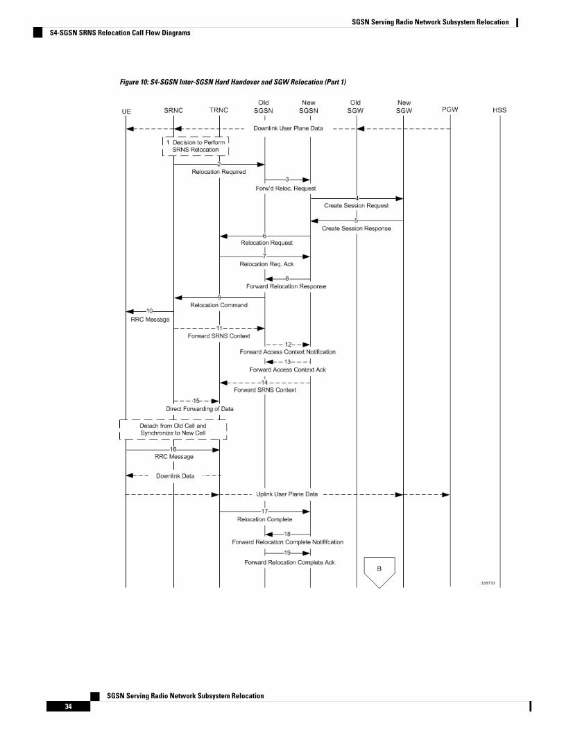
Figure 10: S4-SGSN Inter-SGSN Hard Handover and SGW Relocation (Part 1)
SGSN Serving Radio Network Subsystem Relocation34
SGSN Serving Radio Network Subsystem RelocationS4-SGSN SRNS Relocation Call Flow Diagrams
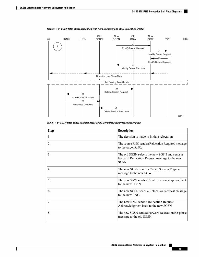
Figure 11: S4-SGSN Inter-SGSN Relocation with Hard Handover and SGW Relocation (Part 2)
Table 11: S4-SGSN Inter-SGSN Hard Handover with SGW Relocation Process Description
DescriptionStep
The decision is made to initiate relocation.1
The source RNC sends a RelocationRequiredmessageto the target RNC.
2
The old SGSN selects the new SGSN and sends aForward Relocation Request message to the newSGSN.
3
The new SGSN sends a Create Session Requestmessage to the new SGW.
4
The new SGW sends a Create Session Response backto the new SGSN.
5
The new SGSN sends a Relocation Request messageto the new RNC.
6
The new RNC sends a Relocation RequestAcknowledgment back to the new SGSN.
7
The new SGSN sends a Forward Relocation Responsemessage to the old SGSN.
8
SGSN Serving Radio Network Subsystem Relocation35
SGSN Serving Radio Network Subsystem RelocationS4-SGSN SRNS Relocation Call Flow Diagrams
DescriptionStep
The old SGSN sends a Relocation Command to theold RNC.
9
The old RNC sends the RRCmessage to the UE. Uponreception of this message the UE will remove anyEPS bearers for which it did not receive thecorresponding EPS radio bearers in the target cell.
10
The old RNC sends a Forward SRNSContextmessageto the old SGSN.
11
The old SGSN sends a Forward Access ContextNotification message to the new SGSN.
12
The new SGSN sends a Forward Access ContextAcknowledge message to the old SGSN
13
The new SGSN sends a Forward SRNS Contextmessage to the new RNC. At this point, the UEdetaches from the old RNC and attaches to the newRNC.
14
The source RNC should start direct forwarding ofdownlink data from the source RNC towards the targetRNC for bearers subject to data forwarding.
15
The UE sends an RRC message to the new RNC.Downlink packets forwarded from the old RNC canbe sent to the UE. In addition, uplink packets can besent from the UE, which are forwarded to the newSGW and then on to the PGW.
16
The new RNC sends a Relocation Complete messageto the new SGSN.
17
The new SGSN then ends a Forward RelocationComplete Notification message to the old SGSN.
18
The old SGSN sends a Forward Relocation CompleteAcknowledgement message to the new SGSN.
19
The new SGSN sends a Modify Bearer Requestmessage to the new SGW for each PDN connection.
20
The new SGW sends a Modify Bearer Requestmessage to the PGW.
21
The PGW sends a Modify Bearer Response messageto the new SGW.
22
SGSN Serving Radio Network Subsystem Relocation36
SGSN Serving Radio Network Subsystem RelocationS4-SGSN SRNS Relocation Call Flow Diagrams
DescriptionStep
The new SGW sends a Modify Bearer Responsemessage to the new SGSN. The PGW begins sendingdownlink packets to the new SGW, which in turnsends them to the new RNC, and then to the UE.
23
The UE initiates a Routing Area Update procedure.This RAU occurs on a RANAP Direct Transfer andtherefore does not involve a Context transfer with thepeer SGSN.
24
The old SGSN sends a Delete Session Request to theold SGW.
25
The old SGSN sends an Iu Release Command to theold RNC.
26
The old RNC then sends a Iu Release Completemessage to the old SGSN.
27
The old SGW sends a Delete Session Responsemessage to the old SGSN.
28
Standards ComplianceThe SGSN SRNS Relocation feature complies with the following standards:
• SGSN Gn/Gp SRNS Relocation: 3GPP TS 23.060 V8.10.0 (2010-09): 3rd Generation PartnershipProject Technical Specification Group Services and System Aspects General Packet Radio Service(GPRS) Service description Stage 2 (Release 8)
• S4-SGSN (S3/S16) SRNS Relocation: 3GPP TS 23.060 V9.8.0 (2011-03): 3rd Generation PartnershipProject Technical Specification Group Services and System Aspects General Packet Radio Service(GPRS) Service description Stage 2 (Release 9)
• MME to 3G SGSN Hard Handover and Relocation: LTE General Packet Radio Service (GPRS)enhancements for Evolved Universal Terrestrial Radio Access Network (E-UTRAN) access (3GPP TS23.401 version 9.8.0 Release 9)
Configuring SRNS Relocation on the SGSNThis section provides examples of how to configure the SRNS relocation feature on the SGSN. An optionalconfiguration example is also provided for enabling IDFT.
Configuring the SRNS Relocation FeatureConfiguring the SRNS Relocation feature includes creating a call-control-profile and then enabling intra-and/or inter-SGSN SRNS relocation via the Command Line Interface (CLI).
configcall-control-profile cc-profile name
SGSN Serving Radio Network Subsystem Relocation37
SGSN Serving Radio Network Subsystem RelocationStandards Compliance
srns-intra all failure-code integer
srns-inter all failure-code integer
endconfig
context context_name
iups-service iups_service_name
inter-rnc-procedures source-rnc-as-target
Notes:
• cc-profile-name is the name assigned to this call-control-profile• srns-intra all enables intra-SGSN SRNS relocations for all location areas.• srns-inter all enables inter-SGSN SRNS relocations for all location areas.• failure-code integer specifies the failure code that applies to SRNS relocations.• Optionally, operators can use the restrict and allow keywords to identify specific location areas whereSRNS relocation will, or will not, occur. For detailed information on these optional keywords, refer tothe Command Line Reference.
• inter-rnc-procedures source-rnc-as-target:Optional. Configures the SGSN to support SRNS relocationfor those scenarios where the source RNC is behaving as the target RNC. The default is not to allowSRNS relocation in those scenarios.
Enabling IDFT (Optional, S4-SGSN Only)To enable support of IDFT between the eNodeB and a specified RNC via the SGW during connected modehandovers on the S4-SGSN:
configcontext context_name
iups-service iups_service_name
rnc id rnc_id
no enb-direct-data-forwardend
Where:
• no enb-direct-data-forward enables the setup of IDFT between the eNodeB and the RNC via the SGWfor connected mode inter RAT handovers. If IDFT is enabled, the SGSN/MME will send the IDFTrequest towards the SGW.
• To disable IDFT, enter the enb-direct-data-forward command.
Verifying the SRNS Feature ConfigurationThis section describes how to verify that SRNS feature configuration.
The following commands provide information on how the SRNS relocation feature is configured:
show call-control-profile full allshow call-control-profile full name cc-profile-name
The output of these commands includes the complete SRNS configuration for the specified Call ControlProfile. For example:
show call-control-profile name cc-profile-name... ... ...SRNS Intra All : Allow
SGSN Serving Radio Network Subsystem Relocation38
SGSN Serving Radio Network Subsystem RelocationEnabling IDFT (Optional, S4-SGSN Only)
SRNS Intra All Failure Code : 10SRNS Inter All : AllowSRNS Inter All Failure Code : 15... ... ...
The following command provides information on how IDFT is configured:
show iups-service name service_name
The output of this command indicates whether IDFT is enabled or disabled for the RNC configuration. If theE-Node Direct Data Forwarding setting reads "Disabled," then IDFT is enabled. If it reads "Enabled," thenIDFT is disabled.
show iups-service name service-name
.. .. ..
Available RNC:
.. .. ..
E-NodeB Direct Data Forwarding : Disabled
.. .. ..
Monitoring and Troubleshooting SRNS RelocationThis section provides information that assists operators in monitoring and troubleshooting the SRSNRelocationfeature.
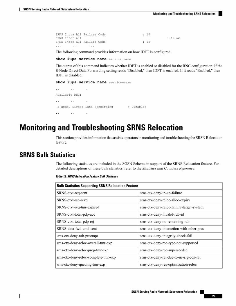
SRNS Bulk StatisticsThe following statistics are included in the SGSN Schema in support of the SRNS Relocation feature. Fordetailed descriptions of these bulk statistics, refer to the Statistics and Counters Reference.
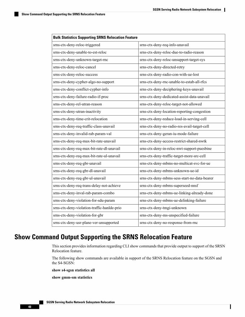
Table 12: SRNS Relocation Feature Bulk Statistics
Bulk Statistics Supporting SRNS Relocation Feature
srns-ctx-deny-ip-up-failureSRNS-ctxt-req-sent
srns-ctx-deny-reloc-alloc-expirySRNS-ctxt-rsp-rcvd
srns-ctx-deny-reloc-failure-target-systemSRNS-ctxt-req-tmr-expired
srns-ctx-deny-invalid-rdb-idSRNS-ctxt-total-pdp-acc
srns-ctx-deny-no-remaining-rabSRNS-ctxt-total-pdp-rej
srns-ctx-deny-interaction-with-other-procSRNS-data-fwd-cmd-sent
srns-ctx-deny-integrity-check-failsrns-ctx-deny-rab-preempt
srns-ctx-deny-req-type-not-supportedsrns-ctx-deny-reloc-overall-tmr-exp
srns-ctx-deny-req-superseededsrns-ctx-deny-reloc-prep-tmr-exp
srns-ctx-deny-rel-due-to-ue-sig-con-relsrns-ctx-deny-reloc-complete-tmr-exp
srns-ctx-deny-res-optimization-relocsrns-ctx-deny-queuing-tmr-exp
SGSN Serving Radio Network Subsystem Relocation39
SGSN Serving Radio Network Subsystem RelocationMonitoring and Troubleshooting SRNS Relocation
Bulk Statistics Supporting SRNS Relocation Feature
srns-ctx-deny-req-info-unavailsrns-ctx-deny-reloc-triggered
srns-ctx-deny-reloc-due-to-radio-reasonsrns-ctx-deny-unable-to-est-reloc
srns-ctx-deny-reloc-unsupport-target-syssrns-ctx-deny-unknown-target-rnc
srns-ctx-deny-directed-retrysrns-ctx-deny-reloc-cancel
srns-ctx-deny-radio-con-with-ue-lostsrns-ctx-deny-reloc-success
srns-ctx-deny-rnc-unable-to-estab-all-rfcssrns-ctx-deny-cypher-algo-no-support
srns-ctx-deny-deciphering-keys-unavailsrns-ctx-deny-conflict-cypher-info
srns-ctx-deny-dedicated-assist-data-unavailsrns-ctx-deny-failure-radio-if-proc
srns-ctx-deny-reloc-target-not-allowedsrns-ctx-deny-rel-utran-reason
srns-ctx-deny-location-reporting-congestionsrns-ctx-deny-utran-inactivity
srns-ctx-deny-reduce-load-in-serving-cellsrns-ctx-deny-time-crit-relocation
srns-ctx-deny-no-radio-res-avail-target-cellsrns-ctx-deny-req-traffic-class-unavail
srns-ctx-deny-geran-iu-mode-failuresrns-ctx-deny-invalid-rab-param-val
srns-ctx-deny-access-restrict-shared-nwtksrns-ctx-deny-req-max-bit-rate-unavail
srns-ctx-deny-in-reloc-nwt-support-puesbinesrns-ctx-deny-req-max-bit-rate-dl-unavail
srns-ctx-deny-traffic-target-more-src-cellsrns-ctx-deny-req-max-bit-rate-ul-unavail
srns-ctx-deny-mbms-no-multicat-svc-for-uesrns-ctx-deny-req-gbr-unavail
srns-ctx-deny-mbms-unknown-ue-idsrns-ctx-deny-req-gbr-dl-unavail
srns-ctx-deny-mbms-sess-start-no-data-bearersrns-ctx-deny-req-gbr-ul-unavail
srns-ctx-deny-mbms-superseed-nnsfsrns-ctx-deny-req-trans-delay-not-achieve
srns-ctx-deny-mbms-ue-linking-already-donesrns-ctx-deny-inval-rab-param-combo
srns-ctx-deny-mbms-ue-delinking-failuresrns-ctx-deny-violation-for-sdu-param
srns-ctx-deny-tmgi-unknownsrns-ctx-deny-violation-traffic-hanlde-prio
srns-ctx-deny-ms-unspecified-failuresrns-ctx-deny-violation-for-gbr
srns-ctx-deny-no-response-from-rncsrns-ctx-deny-usr-plane-ver-unsupported
Show Command Output Supporting the SRNS Relocation FeatureThis section provides information regarding CLI show commands that provide output to support of the SRSNRelocation feature.
The following show commands are available in support of the SRNS Relocation feature on the SGSN andthe S4-SGSN:
show s4-sgsn statistics all
show gmm-sm statistics
SGSN Serving Radio Network Subsystem Relocation40
SGSN Serving Radio Network Subsystem RelocationShow Command Output Supporting the SRNS Relocation Feature
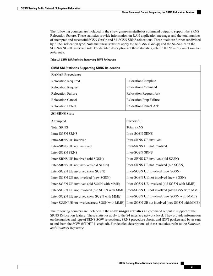
The following counters are included in the show gmm-sm statistics command output to support the SRNSRelocation feature. These statistics provide information on RAN application messages and the total numberof attempted and successful SGSNGn/Gp and S4-SGSN SRNS relocations. These totals are further subdividedby SRNS relocation type. Note that these statistics apply to the SGSN (Gn/Gp) and the S4-SGSN on theSGSN-RNC-UE interface side. For detailed descriptions of these statistics, refer to the Statistics and CountersReference.
Table 13: GMM SM Statistics Supporting SRNS Relocation
GMM SM Statistics Supporting SRNS Relocation
RANAP Procedures
Relocation Complete
Relocation Command
Relocation Request Ack
Relocation Prep Failure
Relocation Cancel Ack
Relocation Required
Relocation Request
Relocation Failure
Relocation Cancel
Relocation Detect
3G-SRNS Stats
Successful
Total SRNS
Intra-SGSN SRNS
Intra-SRNS UE involved
Intra-SRNS UE not involved
Inter-SGSN SRNS
Inter-SRNS UE involved (old SGSN)
Inter-SRNS UE not involved (old SGSN)
Inter-SGSN UE involved (new SGSN)
Inter-SGSN UE not involved (new SGSN)
Inter-SGSN UE involved (old SGSN with MME)
Inter-SGSN UE not involved (old SGSN with MME
Inter-SGSN UE involved (new SGSN with MME)
Inter-SGSNUE not involved (new SGSNwithMME)
Attempted
Total SRNS
Intra-SGSN SRNS
Intra-SRNS UE involved
Intra-SRNS UE not involved
Inter-SGSN SRNS
Inter-SRNS UE involved (old SGSN)
Inter-SRNS UE not involved (old SGSN)
Inter-SGSN UE involved (new SGSN)
Inter-SGSN UE not involved (new SGSN)
Inter-SGSN UE involved (old SGSN with MME)
Inter-SGSN UE not involved (old SGSN with MME
Inter-SGSN UE involved (new SGSN with MME)
Inter-SGSNUE not involved (new SGSNwithMME)
The following counters are included in the show s4-sgsn statistics all command output in support of theSRNS Relocation feature. These statistics apply to the S4 interface network level. They provide informationon the number and type of SRNS SGW relocations, SRNS procedure aborts, and IDFT packets and bytes sentto and from the SGW (if IDFT is enabled). For detailed descriptions of these statistics, refer to the Statisticsand Counters Reference.
SGSN Serving Radio Network Subsystem Relocation41
SGSN Serving Radio Network Subsystem RelocationShow Command Output Supporting the SRNS Relocation Feature
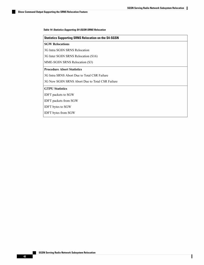
Table 14: Statistics Supporting S4-SGSN SRNS Relocation
Statistics Supporting SRNS Relocation on the S4-SGSN
SGW Relocations
3G Intra SGSN SRNS Relocation
3G Inter SGSN SRNS Relocation (S16)
MME-SGSN SRNS Relocation (S3)
Procedure Abort Statistics
3G Intra SRNS Abort Due to Total CSR Failure
3G New SGSN SRNS Abort Due to Total CSR Failure
GTPU Statistics
IDFT packets to SGW
IDFT packets from SGW
IDFT bytes to SGW
IDFT bytes from SGW
SGSN Serving Radio Network Subsystem Relocation42
SGSN Serving Radio Network Subsystem RelocationShow Command Output Supporting the SRNS Relocation Feature