sfa 5.28 especificacion
TRANSCRIPT
2007 SECTION II, PART C SFA-5.28/SFA-5.28M
SPECIFICATION FOR LOW-ALLOY STEELELECTRODES AND RODS FOR GAS SHIELDED ARC
WELDING
SFA-5.28/SFA-5.28M
(Identical with AWS Specification A5.28/A5.28M:2005. In case of dispute, the original AWS text applies.)
1. Scope1.1 This specification prescribes requirements for the
classification of low-alloy steel electrodes (solid, compos-ite stranded and composite metal cored) and rods (solid)for gas metal arc (GMAW), gas tungsten arc (GTAW),and plasma arc (PAW) welding.
1.2 Safety and health issues and concerns are beyondpthe scope of this standard and therefore are not fullyaddressed herein. Some safety and health information canbe found in the nonmandatory Sections A5 and A10. Safetyand health information is available from other sources,including but not limited to ANSI Z49.1, Safety in Welding,Cutting, and Allied Processes, and applicable federal andstate regulations.
1.3 This specification makes use of both U.S. Custom-ary Units and the International System of Units (SI). Themeasurements are not exact equivalents; therefore, eachsystem must be used independently of the other withoutcombining in any way when referring to weld metal proper-ties. The specification with the designation A5.28 uses U.S.Customary Units. The specification A5.28M uses SI Units.The latter are shown within brackets [ ] or in appropriatecolumns in tables and figures. Standard dimensions basedon either system may be used for sizing of electrodes orpackaging or both under the A5.28 or A5.28M specifica-tions.
PART A — GENERAL REQUIREMENTS
2. Normative References
The following standards contain provisions which,through reference in this text, constitute provisions of thisAWS standard. For dated references, subsequent amend-ments to, or revisions of, any of these publications do not
613
apply. However, parties to agreement based on this AWSstandard are encouraged to investigate the possibility ofapplying the most recent editions of the documents shownbelow. For undated references, the latest edition of thestandard applies.
2.1 ASTM Standards1
(a) A 36/A 36M, Specification for Carbon StructuralSteel
(b) A 203/A 203M, Specification for Pressure VesselPlates, Alloy Steel, Nickel
(c) A 285/A 285M, Specification for Pressure VesselPlates, Carbon Steel, Low- and Intermediate-TensileStrength
(d) A 387/A 387M, Specification for Pressure VesselPlates, Alloy Steel, Chromium-Molybdenum
(e) A 515/A 515M, Specification for Pressure VesselPlates, Carbon Steel, for Intermediate- and Higher-Tem-perature Service
(f) A 516/A 516M, Specification for Pressure VesselPlates, Carbon Steel, for Moderate- and Lower-Tempera-ture Service
(g) A 537/A 537M, Specification for Pressure VesselPlates, Heat-Treated, Carbon-Manganese-Silicon Steel
(h) E 29, Standard Practice for Using Significant Digitsin Test Data to Determine Conformance with Specifications
(i) E 350, Standard Test Method for Chemical Analysisof Carbon Steel, Low Alloy Steel, Silicon Electrical Steel,Ingot Iron and Wrought Iron
(j) E 1032, Standard Test Method for RadiographicExamination of Weldments
1 ASTM standards are published by the American Society for Testingand Materials, 100 Barr Harbor Drive, West Conshohocken, PA 19428.
Copyright ASME International Provided by IHS under license with ASME
Not for ResaleNo reproduction or networking permitted without license from IHS
--`,,```,,,,````-`-`,,`,,`,`,,`---
SFA-5.28/SFA-5.28M 2007 SECTION II, PART C
2.2 AWS Standards2
(a) AWS A5.01, Filler Metal Procurement Guidelines(b) AWS A5.32/A5.32M, Specification for Welding
Shielding Gases(c) AWS A4.3, Standard Methods for Determination of
the Diffusible Hydrogen Content of Martensitic, Bainitic,and Ferritic Steel Weld Metal Produced by Arc Welding
(d) AWS B4.0, Standard Methods for Mechanical Test-ing of Welds
(e) AWS B4.0M, Standard Methods for MechanicalTesting of Welds
2.3 ANSI Standard3
(a) ANSI Z49.1, Safety in Welding, Cutting, and AlliedProcesses
2.4 ISO Specification4
(a) ISO 544, Welding consumables—Technical deliveryconditions for welding filler materials—Type of product,dimensions, tolerances and markings
2.5 Department of Defense Specification5
(a) MIL-S-16216, Military Specification, Steel Plate,Alloy, Structural, High Yield Strength (HY-80 and HY-100)
3. Classification3.1 The solid electrodes (and rods) covered by this
A5.28 specification utilize a classification system basedupon U.S. Customary Units and are classified accordingto the chemical composition of the electrode, as specifiedin Table 1, and the mechanical properties of the weld metal,as specified in Tables 3 and 4. The composite strandedelectrodes and composite metal cored electrodes coveredby this specification also utilize a classification systembased upon U.S. Customary Units and are classifiedaccording to the chemical composition and mechanicalproperties of the weld metal as specified in Tables 2, 3,and 4, and the shielding gas employed.
3.1M The solid electrodes (and rods) covered by thisA5.28M specification utilize a classification system basedupon the International System of Units (SI) and are classi-fied according to the chemical composition of the electrode,as specified in Table 1, and the mechanical properties of theweld metal, as specified in Tables 3 and 4. The compositestranded electrodes and composite metal cored electrodes
2 AWS standards are published by the American Welding Society, 550N.W. LeJeune Road, Miami, FL 33126.
3 ANSI standards are published by the American National StandardsInstitute, 25 West 43rd Street, 4th Floor, New York, NY 10036.
4 ISO standards are published by the International Organization forStandardization, 1, rue de Varembe, Case postale 56, CH-1211 Geneva20, Switzerland.
5 Department of Defense standards are published by DODSSP, Stan-dardization Documents Order Desk, 700 Robbins Avenue, Bldg. 4D,Philadelphia, PA 19111-5094.
614
covered by this specification also utilize a classificationsystem based upon the International System of Units (SI)and are classified according to the chemical compositionand mechanical properties of the weld metal as specifiedin Tables 2, 3, and 4, and the shielding gas employed.
3.2 Electrodes and rods classified under one classifica-tion shall not be classified under any other classificationin this specification, except that ER80S-D2 [ER55S-D2]may also be classified as ER90S-D2 [ER62S-D2] providedthe product meets the requirements of both classifications.However, material may be classified under both A5.28AND A5.28M specifications.
3.3 The welding electrodes and rods classified underthis specification are intended for gas shielded arc welding,but that is not to prohibit their use with any other process(or any other shielding gas, or combination of shieldinggases) for which they are found suitable.
4. Acceptance
Acceptance6 of the electrodes and rods shall be in accor-dance with the provisions of AWS A5.01.
5. Certification
By affixing the AWS specification and classificationdesignations to the packaging, or the classification to theproduct, the manufacturer certifies that the product meetsthe requirements of this specification.7
6. Rounding-Off Procedure
For the purpose of determining conformance with thisspecification, an observed or calculated value shall berounded to the nearest 1000 psi [10 MPa] for tensile andyield strength, and to the “nearest unit” in the last right-hand place of figures used in expressing the limiting valuefor other quantities in accordance with the rounding-offmethod given in ASTM E 29.
PART B — TESTS, PROCEDURES, ANDREQUIREMENTS
7. Summary of Tests7.1 The tests required for each classification are speci-
fied in Table 5. The purpose of these tests is to determinethe chemical composition, the mechanical properties, andsoundness of the weld metal. The base metal for the weldtest assemblies, the welding and testing procedures to be
6 See Section A3, Acceptance, for further information concerningacceptance, testing of the material shipped, and AWS A5.01.
7 See Section A4, Certification, for further information concerningcertification and the testing called for to meet this requirement.
Copyright ASME International Provided by IHS under license with ASME
Not for ResaleNo reproduction or networking permitted without license from IHS
--`,,```,,,,````-`-`,,`,,`,`,,`---

2008a SECTION II, PART C SFA-5.28/SFA-5.28M
07
TA
BL
E1
A08
CH
EM
ICA
LC
OM
PO
SIT
ION
RE
QU
IRE
ME
NT
SF
OR
SO
LID
EL
EC
TR
OD
ES
AN
DR
OD
S
AW
SC
lass
ifica
tion
c
A5.
28A
5.28
MU
NS
Num
berd
Wei
ght
Per
cent
a,b
CM
nS
iP
SN
iC
rM
oV
Ti
Zr
Al
Cue
Oth
erE
lem
ents
Tot
al
Car
bon-
Mol
ybde
num
Ste
elE
lect
rode
san
dR
ods
ER
70S
-A1
ER
49S
-A1
K11
235
0.12
1.30
0.30
–0.7
00.
025
0.02
50.
20—
0.40
–0.6
5—
——
—0.
350.
50
Chr
omiu
m-M
olyb
denu
mS
teel
Ele
ctro
des
and
Rod
s
ER
80S
-B2
ER
55S
-B2
K20
900
0.07
–0.1
20.
40–0
.70
0.40
–0.7
00.
025
0.02
50.
201.
20–1
.50
0.40
–0.6
5—
——
—0.
350.
50E
R70
S-B
2LE
R49
S-B
2LK
2050
00.
050.
40–0
.70
0.40
–0.7
00.
025
0.02
50.
201.
20–1
.50
0.40
–0.6
5—
——
—0.
350.
50E
R90
S-B
3E
R62
S-B
3K
3096
00.
07–0
.12
0.40
–0.7
00.
40–0
.70
0.02
50.
025
0.20
2.30
–2.7
00.
90–1
.20
——
——
0.35
0.50
ER
80S
-B3L
ER
55S
-B3L
K30
560
0.05
0.40
–0.7
00.
40–0
.70
0.02
50.
025
0.20
2.30
–2.7
00.
90–1
.20
——
——
0.35
0.50
ER
80S
-B6
fE
R55
S-B
6fS
5028
00.
100.
40–0
.70
0.50
0.02
50.
025
0.60
4.50
–6.0
00.
45–0
.65
——
——
0.35
0.50
ER
80S
-B8g
ER
55S
-B8g
S50
480
0.10
0.40
–0.7
00.
500.
025
0.02
50.
508.
00–1
0.50
0.80
–1.2
0—
——
—0.
350.
50E
R90
S-B
9h,i,j
ER
62S
-B9h,
i,jS
5048
20.
07–0
.13
1.20
0.15
–0.5
00.
010
0.01
00.
808.
00–1
0.50
0.85
–1.2
00.
15–0
.30
——
0.04
0.20
0.50
Nic
kel
Ste
elE
lect
rode
san
dR
ods
ER
80S
-Ni1
ER
55S
-NI1
K11
260
0.12
1.25
0.40
–0.8
00.
025
0.02
50.
80–1
.10
0.15
0.35
0.05
——
—0.
350.
50E
R80
S-N
i2E
R55
S-N
I2K
2124
00.
121.
250.
40–0
.80
0.02
50.
025
2.00
–2.7
5—
——
——
—0.
350.
50E
R80
S-N
i3E
R55
S-N
I3K
3124
00.
121.
250.
40–0
.80
0.02
50.
025
3.00
–3.7
5—
——
——
—0.
350.
50
Man
gane
se-M
olyb
denu
mS
teel
Ele
ctro
des
and
Rod
s
ER
80S
-D2
ER
55S
-D2
K10
945
0.07
–0.1
21.
60–2
.10
0.50
–0.8
00.
025
0.02
50.
15—
0.40
–0.6
0—
——
—0.
500.
50E
R90
S-D
2E
R62
S-D
2
Oth
erL
ow-A
lloy
Ste
elE
lect
rode
san
dR
ods
ER
100S
-1E
R69
S-1
K10
882
0.08
1.25
–1.8
00.
20–0
.55
0.01
00.
010
1.40
–2.1
00.
300.
25–0
.55
0.05
0.10
0.10
0.10
0.25
0.50
ER
110S
-1E
R76
S-1
K21
015
0.09
1.40
–1.8
00.
20–0
.55
0.01
00.
010
1.90
–2.6
00.
500.
25–0
.55
0.04
0.10
0.10
0.10
0.25
0.50
ER
120S
-1E
R83
S-1
K21
030
0.10
1.40
–1.8
00.
25–0
.60
0.01
00.
010
2.00
–2.8
00.
600.
30–0
.65
0.03
0.10
0.10
0.10
0.25
0.50
ER
XX
S-G
ER
XX
S-G
—N
otS
peci
fiedk
NO
TE
S:
a.T
hefil
ler
met
alsh
all
bean
alyz
edfo
rth
eel
emen
tsfo
rw
hich
valu
esar
esh
own
inth
ista
ble.
Ifth
epr
esen
ceof
othe
rel
emen
tsis
indi
cate
din
the
cour
seof
this
wor
k,th
eam
ount
ofth
ose
elem
ents
shal
lbe
dete
rmin
edto
ensu
reth
atth
eir
tota
l(e
xclu
ding
iron
)do
esno
tex
ceed
the
limit
ssp
ecifi
edfo
r“O
ther
Ele
men
ts,
Tot
al.”
b.S
ingl
eva
lues
are
max
imum
.c.
The
suffi
xes
B2,
Ni1
,et
c.,
desi
gnat
eth
ech
emic
alco
mpo
siti
onof
the
elec
trod
ean
dro
dcl
assi
ficat
ion.
d.S
AE
HS
-108
6/A
ST
MD
S-5
6H,
Met
als
and
Allo
ysin
the
Uni
fied
Num
beri
ngS
yste
m.
e.C
oppe
rdu
eto
any
coat
ing
onth
eel
ectr
ode
orro
dpl
usth
eco
pper
cont
ent
ofth
efil
ler
met
alit
self
,sh
all
not
exce
edth
est
ated
0.50
%m
ax.
f.S
imila
rto
form
ercl
ass
ER
502
inA
WS
Spe
cific
atio
nA
5.9-
93.
g.S
imila
rto
form
ercl
ass
ER
505
inA
WS
Spe
cific
atio
nA
5.9-
93.
h.N
iobi
um(C
olum
bium
)0.
02–0
.10%
i.N
itro
gen
0.03
–0.0
7%j.
The
sum
ofM
nan
dN
ish
all
bele
ssth
anor
equa
lto
1.50
%m
ax.
k.In
orde
rto
mee
tth
ere
quir
emen
tsof
the
“G”
clas
sific
atio
n,th
eel
ectr
ode
mus
tha
vea
min
imum
ofon
eor
mor
eof
the
follo
win
g:0.
50%
Nic
kel,
0.30
%C
hrom
ium
,or
0.20
%M
olyb
denu
m.
The
com
posi
tion
shal
lbe
repo
rted
;th
ere
quir
emen
tsar
eth
ose
agre
edto
byth
epu
rcha
ser
and
supp
lier.
615
Copyright ASME International Provided by IHS under license with ASME
Not for ResaleNo reproduction or networking permitted without license from IHS
--`,,```,,,,````-`-`,,`,,`,`,,`---
SFA-5.28/SFA-5.28M 2008a SECTION II, PART C
TA
BL
E2
CH
EM
ICA
LC
OM
PO
SIT
ION
RE
QU
IRE
ME
NT
SF
OR
WE
LD
ME
TA
LF
RO
MC
OM
PO
SIT
EE
LE
CT
RO
DE
Sa
AW
SC
lass
ifica
tion
d
A5.
28A
5.28
MU
NS
Num
bere
Wei
ght
Per
cent
b,c
CM
nS
iP
SN
iC
rM
oV
Ti
Zr
Al
Cu
Oth
erE
lem
ents
Tot
al
Chr
omiu
m-M
olyb
denu
mW
eld
Met
al
E80
C-B
2E
55C
-B2
W52
030
0.05
–0.1
20.
40–1
.00
0.25
–0.6
00.
025
0.03
00.
201.
00–1
.50
0.40
–0.6
50.
03—
——
—0.
50E
70C
-B2L
E49
C-B
2LW
5213
00.
050.
40–1
.00
0.25
–0.6
00.
025
0.03
00.
201.
00–1
.50
0.40
–0.6
50.
03—
——
0.35
0.50
E90
C-B
3E
62C
-B3
W53
030
0.05
–0.1
20.
40–1
.00
0.25
–0.6
00.
025
0.03
00.
202.
00–2
.50
0.90
–1.2
00.
03—
——
0.35
0.50
E80
C-B
3LE
55C
-B3L
W53
130
0.05
0.40
–1.0
00.
25–0
.60
0.02
50.
030
0.20
2.00
–2.5
00.
90–1
.20
0.03
——
—0.
350.
50E
80C
-B6
E55
C-B
60.
100.
40–1
.00
0.25
–0.6
00.
025
0.02
50.
604.
50–6
.00
0.45
–0.6
50.
03—
——
0.35
0.50
E80
C-B
8E
55C
-B8
0.10
0.40
–1.0
00.
25–0
.60
0.02
50.
025
0.20
8.00
–10.
500.
80–1
.20
0.03
——
—0.
350.
50E
90C
-B9
fE
55C
-B9
0.08
–0.1
31.
20g
0.50
0.02
00.
015
0.80
g8.
00–1
0.50
0.85
–1.2
00.
15–0
.30
——
0.04
0.20
0.50
Nic
kel
Ste
elE
lect
rode
san
dR
ods
E80
C-N
i1E
55C
-Ni1
W21
030
0.12
1.50
0.90
0.02
50.
030
0.80
–1.1
0—
0.30
0.03
——
—0.
350.
50E
70C
-Ni2
E49
C-N
i2W
2203
00.
081.
250.
900.
025
0.03
01.
75–2
.75
——
0.30
——
—0.
350.
50E
80C
-Ni2
E55
C-N
i2W
2203
00.
121.
500.
900.
025
0.03
01.
75–2
.75
——
0.03
——
—0.
350.
50E
80C
-Ni3
E55
C-N
i3W
2303
00.
121.
500.
900.
025
0.03
02.
75–3
.75
——
0.03
——
—0.
350.
50
Man
gane
se-M
olyb
denu
mS
teel
Ele
ctro
des
and
Rod
s
E90
C-D
2E
62C
-D2
W19
230
0.12
1.00
–1.9
00.
900.
025
0.03
0—
—0.
40–0
.60
0.03
——
—0.
350.
50
Oth
erL
ow-A
lloy
Ste
elE
lect
rode
san
dR
ods
E90
C-K
3E
62C
-K3
0.15
0.75
–2.2
50.
800.
025
0.02
50.
50–2
.50
0.15
0.25
–0.6
50.
03—
——
0.35
0.50
E10
0C-K
3E
69C
-K3
0.15
0.75
–2.2
50.
800.
025
0.02
50.
50–2
.50
0.15
0.25
–0.6
50.
03—
——
0.35
0.50
E11
0C-K
3E
76C
-K3
0.15
0.75
–2.2
50.
800.
025
0.02
50.
50–2
.50
0.15
0.25
–0.6
50.
03—
——
0.35
0.50
E11
0C-K
4E
76C
-K4
0.15
0.75
–2.2
50.
800.
025
0.02
50.
50–2
.50
0.15
–0.6
50.
25–0
.65
0.03
——
—0.
350.
50E
120C
-K4
E83
C-K
40.
150.
75–2
.25
0.80
0.02
50.
025
0.50
–2.5
00.
15–0
.65
0.25
–0.6
50.
03—
——
0.35
0.50
E80
C-W
2E
55C
-W2
0.12
0.50
–1.3
00.
35–0
.80
0.02
50.
030
0.40
–0.8
00.
45–0
.70
—0.
03—
——
0.30
–0.7
50.
50E
XX
C-G
EX
XC
-G—
Not
Spe
cifie
dh
NO
TE
S:
a.C
hem
ical
requ
irem
ents
for
com
posi
teel
ectr
odes
are
base
don
anal
ysis
ofth
eir
wel
dm
etal
inth
eas
-wel
ded
cond
itio
nus
ing
the
shie
ldin
gga
ssp
ecifi
edin
Tab
le3.
b.T
hew
eld
met
alsh
all
bean
alyz
edfo
rth
esp
ecifi
cel
emen
tsfo
rw
hich
valu
esar
esh
own
inth
ista
ble.
Ifth
epr
esen
ceof
othe
rel
emen
tsis
indi
cate
din
the
cour
seof
this
wor
k,th
eam
ount
ofth
ose
elem
ents
shal
lbe
dete
rmin
edto
ensu
reth
atth
eir
tota
l(e
xclu
ding
iron
)do
esno
tex
ceed
the
limit
spec
ified
for
“Oth
erE
lem
ents
,T
otal
.”c.
Sin
gle
valu
esar
em
axim
um.
d.S
olid
elec
trod
esar
ege
nera
llyre
com
men
ded
for
gas
tung
sten
arc
wel
ding
(GT
AW
)or
plas
ma
arc
wel
ding
(PA
W).
e.S
AE
/H
S-1
086/
AS
TM
DS
-56H
,M
etal
&A
lloys
inth
eU
nifie
dN
umbe
ring
Sys
tem
.f.
Nio
bium
(Col
umbi
um)
0.02
–0.1
0%,
Nit
roge
n0.
03–0
.07%
.g.
The
sum
ofM
nan
dN
ish
all
be1.
50%
max
.h.
Inor
der
tom
eet
the
requ
irem
ents
ofth
e“G
”cl
assi
ficat
ion,
the
elec
trod
em
ust
have
am
inim
umof
one
orm
ore
ofth
efo
llow
ing:
0.50
%N
icke
l,0.
30%
Chr
omiu
m,
or0.
20%
Mol
ybed
enum
.T
heco
mpo
siti
onsh
all
bere
port
ed;
the
requ
irem
ents
are
thos
eag
reed
toby
the
purc
hase
ran
dsu
pplie
r.
616
Copyright ASME International Provided by IHS under license with ASME
Not for ResaleNo reproduction or networking permitted without license from IHS
--`,,```,,,,````-`-`,,`,,`,`,,`---

2007 SECTION II, PART C SFA-5.28/SFA-5.28M
TABLE 3TENSION TEST REQUIREMENTS
Tensile Strength Yield Strengthb
AWS Classification Elongation(minimuim) (minimum) Percent Testing
A5.28 A5.28M Shielding Gasa psi MPa psi MPa (minimum) Condition
ER70S-B2L ER49S-B2L75,000 515 58,000 400 19ER70C-B2L E49C-B2L
ER70S-A1 ER49S-A1
ER80S-B2 ER55S-B2 80,000 550 68,000 470 19E80C-B2 E55C-B2
Argon/1–5% O2ER80S-B3L ER55S-B3L 80,000 550 68,000 470 17(Classes SG-AO-1E80C-B3L E55C-B3Lthru SG-AO-5)
ER90S-B3 ER62S-B3 90,000 620 78,000 540 17PWHTcE90C-B3 E62C-B3
ER80S-B6 ER55S-B6 80,000 550 68,000 470 17
E80C-B6 E55C-B6 80,000 550 68,000 470 17
ER80S-B8 ER55S-B8 80,000 550 68,000 470 17
E80C-B8 E55C-B8 80,000 550 68,000 470 17
Argon/5% CO2
ER90S-B9 ER62S-B9 (Class SG-AC-5)
90,000 620 60,000 410 16Argon/5-25% CO2
E90C-B9 E62C-B9 (Classes SG-AC-5thru SG-AC-25)
E70C-Ni2 E49C-Ni2 70,000 480 58,000 400 24 PWHTc
ER80S-Ni1 ER55S-Ni1 Argon/1–5% O2 80,000 550 68,000 470 24 As-WeldedE80C-Ni1 E55C-Ni1 (Classes SG-AO-1
thru SG-AO-5)ER80S-Ni2 ER55S-Ni2E80C-Ni2 E55C-Ni2
80,000 550 68,000 470 24 PWHTc
ER80S-Ni3 ER55S-Ni3E80C-Ni3 E55C-Ni3
ER80S-D2 ER55S-D2 CO2 (Class SG-C) 80,000 550 68,000 470 17 As-Welded
Argon/1–5% O2ER90S-D2 ER62S-D2(Classes SG-AO-1 90,000 620 78,000 540 17 As-Welded
E90C-D2 E62C-D2thru SG-AO-5)
ER100S-1 ER69S-1 100,000 690 88,000 610 16
ER110S-1 ER76S-1 Argon/2% O2 110,000 760 95,000 660 15As-Welded
(Class SG-AO-2)ER120S-1 ER83S-1 120,000 830 105,000 730 14
617
Copyright ASME International Provided by IHS under license with ASME
Not for ResaleNo reproduction or networking permitted without license from IHS
--`,,```,,,,````-`-`,,`,,`,`,,`---
SFA-5.28/SFA-5.28M 2007 SECTION II, PART C
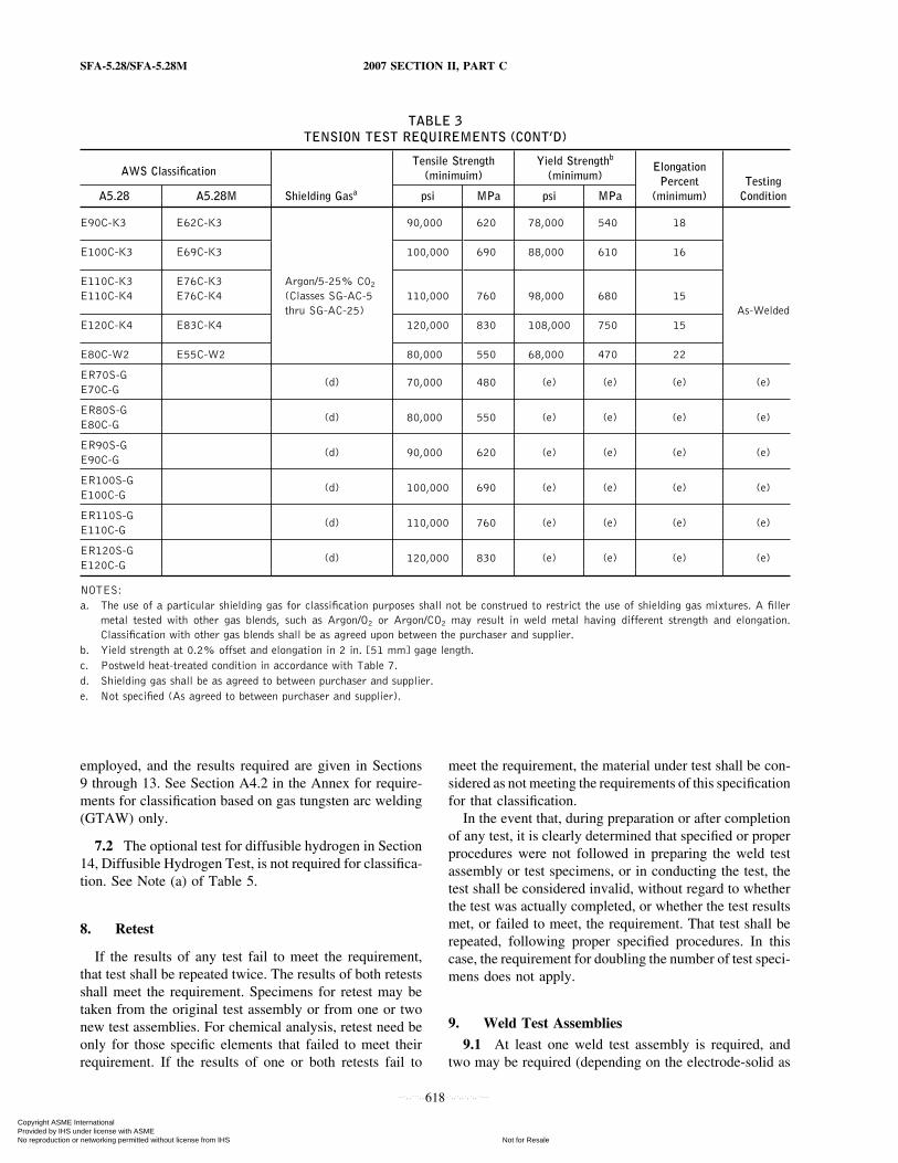
TABLE 3TENSION TEST REQUIREMENTS (CONT’D)
Tensile Strength Yield Strengthb
AWS Classification Elongation(minimuim) (minimum) Percent Testing
A5.28 A5.28M Shielding Gasa psi MPa psi MPa (minimum) Condition
E90C-K3 E62C-K3 90,000 620 78,000 540 18
E100C-K3 E69C-K3 100,000 690 88,000 610 16
E110C-K3 E76C-K3 Argon/5-25% C02
E110C-K4 E76C-K4 (Classes SG-AC-5 110,000 760 98,000 680 15thru SG-AC-25) As-Welded
E120C-K4 E83C-K4 120,000 830 108,000 750 15
E80C-W2 E55C-W2 80,000 550 68,000 470 22
ER70S-G(d) 70,000 480 (e) (e) (e) (e)
E70C-G
ER80S-G(d) 80,000 550 (e) (e) (e) (e)
E80C-G
ER90S-G(d) 90,000 620 (e) (e) (e) (e)
E90C-G
ER100S-G(d) 100,000 690 (e) (e) (e) (e)
E100C-G
ER110S-G(d) 110,000 760 (e) (e) (e) (e)
E110C-G
ER120S-G(d) 120,000 830 (e) (e) (e) (e)
E120C-G
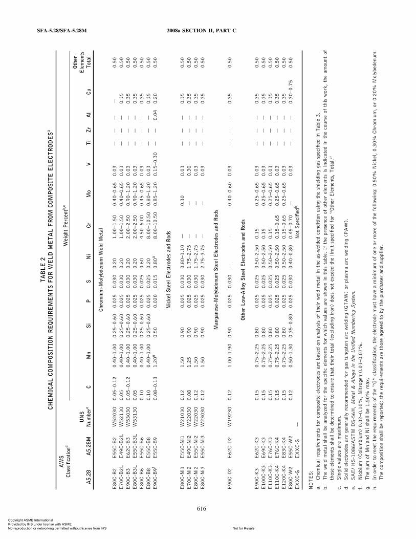
NOTES:a. The use of a particular shielding gas for classification purposes shall not be construed to restrict the use of shielding gas mixtures. A filler
metal tested with other gas blends, such as Argon/O2 or Argon/CO2 may result in weld metal having different strength and elongation.Classification with other gas blends shall be as agreed upon between the purchaser and supplier.
b. Yield strength at 0.2% offset and elongation in 2 in. [51 mm] gage length.c. Postweld heat-treated condition in accordance with Table 7.d. Shielding gas shall be as agreed to between purchaser and supplier.e. Not specified (As agreed to between purchaser and supplier).
employed, and the results required are given in Sections9 through 13. See Section A4.2 in the Annex for require-ments for classification based on gas tungsten arc welding(GTAW) only.
7.2 The optional test for diffusible hydrogen in Section14, Diffusible Hydrogen Test, is not required for classifica-tion. See Note (a) of Table 5.
8. Retest
If the results of any test fail to meet the requirement,that test shall be repeated twice. The results of both retestsshall meet the requirement. Specimens for retest may betaken from the original test assembly or from one or twonew test assemblies. For chemical analysis, retest need beonly for those specific elements that failed to meet theirrequirement. If the results of one or both retests fail to
618
meet the requirement, the material under test shall be con-sidered as not meeting the requirements of this specificationfor that classification.
In the event that, during preparation or after completionof any test, it is clearly determined that specified or properprocedures were not followed in preparing the weld testassembly or test specimens, or in conducting the test, thetest shall be considered invalid, without regard to whetherthe test was actually completed, or whether the test resultsmet, or failed to meet, the requirement. That test shall berepeated, following proper specified procedures. In thiscase, the requirement for doubling the number of test speci-mens does not apply.
9. Weld Test Assemblies
9.1 At least one weld test assembly is required, andtwo may be required (depending on the electrode-solid as
Copyright ASME International Provided by IHS under license with ASME
Not for ResaleNo reproduction or networking permitted without license from IHS
--`,,```,,,,````-`-`,,`,,`,`,,`---

2007 SECTION II, PART C SFA-5.28/SFA-5.28M
TABLE 4IMPACT TEST REQUIREMENTS
AWS Classification Average Impact Energy Absorbeda,b(minimum)
A5.28 A5.28M A5.28 A5.28M Testing Condition
ER70S-A1 ER49S-A1ER70S-B2L ER49S-B2LE70C-B2L E49C-B2LER80S-B2 ER55S-B2E80C-B2 E55C-B2ER80S-B3L ER55S-B3LE80C-B3L E55C-B3LER90S-B3 ER62S-B3 Not Required Not Required —E90C-B3 E62C-B3ER80S-B6 ER55S-B6E380C-B6 E55C-B6ER80S-B8 ER55S-B8E80C-B8 E55C-B8ER90S-B9 ER62S-B9E90C-B9 E62C-B9
ER80S-Ni1 ER55S-Nil20 ft·lbf at −50°F 27 J at −45°C As-Welded
E80C-Ni1 E55C-Nil
E70C-Ni2 E49C-Ni2ER80S-Ni2 ER55S-Ni2 20 ft·lbf at −80°F 27 J at −60°C PWHTb
E80C-Ni2 E55C-Ni2
ER80S-Ni3 ER55S-Ni320 ft·lbf at −100°F 27 J at −75°C PWHTb
E80C-Ni3 E55C-Ni3
ER80S-D2 ER55S-D2ER90S-D2 ER62S-D2 20 ft·lbf at −20°F 27 J at −30°C As-WeldedE90C-D2 E62C-D2
ER100S-1 ER69S-1ER110S-1 ER76S-1 50 ft·lbf at −60°F 68 J at −50°C As-WeldedER120S-1 ER83S-1
E90C-K3 E62C-K3E100C-K3 E69C-K3E110C-K3 E76C-K3 20 ft·lbf at −60°F 27 J at −50°C As-WeldedE110C-K4 E76C-K4E120C-K4 E83C-K4
E80C-W2 E55C-W2 20 ft·lbf at −20°F 27 J at −30°C As-Welded
ERXXS-G ERXXS-G As agreed As agreed—
EXXC-G EXXC-G betweensupplier between supplier—
and purchaser and purchaser
NOTES:a. Both the highest and lowest of the five test values obtained shall be disregarded in computing the average impact energy absorbed.
For classifications requiring 20 ft·lbf [27 J]: Two of the remaining three values shall equal or exceed 20 ft·lbf [27 J]; one of the three remainingvalues may be lower than 20 ft·lbf [27 J], but not lower than 15 ft·lbf [20 J]. The average of the three shall not be less than the 20 ft·lbf [27J] specified.
For classifications requiring 50 ft·lbf [68 J]: Two of the remaining three values shall equal or exceed 50 ft·lbf [68 J]; one of the three remainingvalues may be lower than 50 ft·lbf [68 J], but not lower than 40 ft·lbf [54 J]. The average of the three shall not be less than the 50 ft·lbf [68J] specified.b. Postweld heat treated in accordance with Table 7.
619
Copyright ASME International Provided by IHS under license with ASME
Not for ResaleNo reproduction or networking permitted without license from IHS
--`,,```,,,,````-`-`,,`,,`,`,,`---

SFA-5.28/SFA-5.28M 2007 SECTION II, PART C
TABLE 5REQUIRED TESTS
AWS Classification Chemical Analysis DiffusibleA5.28 A5.28M Electrode Weld Metal Radiographic Test Tension Test Impact Test Hydrogen Test
Solid Electrodes
ER70S-A1 ER49S-A1ER80S-B2 ER55S-B2ER70S-B2L ER49S-B2LER90S-B3 ER62S-B3 Required Not Required Required Required Not Required aER80S-B3L ER55S-B3LER80S-B6 ER55S-B6ER80S-B8 ER55S-B8ER90S-B9 ER62S-B9
ER80S-Ni1 ER55S-Ni1ER80S-Ni2 ER55S-Ni2 Required Not Required Required Required Required aER80S-Ni3 ER55S-Ni3
ER80S-D2 ER55S-D2 Required Not Required Required Required Required aER90S-D2 ER62S-D2
ER100S-1 ER69S-1ER110S-1 ER76S-1 Required Not Required Required Required Required aER120S-1 ER83S-1
ERXXS-G ERXXS-G Requiredb Not Required Required Required Not Required a
Composite Metal Cored Electrodes
E80C-B2 E55C-B2E70C-B2L E49C-B2LE90C-B3 E62C-B3E80C-B3L E55C-B3L Not Required Required Required Required Not Required aE80C-B6 E55C-B6E80C-B8 E55C-B8E90C-B9 E62C-B9
E80C-Ni1 E55C-Ni1E70C-Ni2 E49C-Ni2 Not Required Required Required Required Required aE80C-Ni2 E55C-Ni2E80C-Ni3 E55C-Ni3
E90C-D2 E62C-D2 Not Required Required Required Required Required a
E90C-K3 E62C-K3E100C-K3 E69C-K3E110C-K3 E76C-K3 Not Required Required Required Required Required aE110C-K4 E76C-K4E120C-K4 E83C-K4
E80C-W2 E55C-W2 Not Required Required Required Required Required a
EXXC-G EXXC-G Not Required Requiredb Required Required Not Required a
NOTES:a. Optional diffusible hydrogen test is required only when specified by the puchaser or when the manufacturer puts the diffusible hydrogen
designator on the label (See A2.2 and A8.2).b. To be reported. See A7.19.
620
Copyright ASME International Provided by IHS under license with ASME
Not for ResaleNo reproduction or networking permitted without license from IHS
--`,,```,,,,````-`-`,,`,,`,`,,`---
2007 SECTION II, PART C SFA-5.28/SFA-5.28M
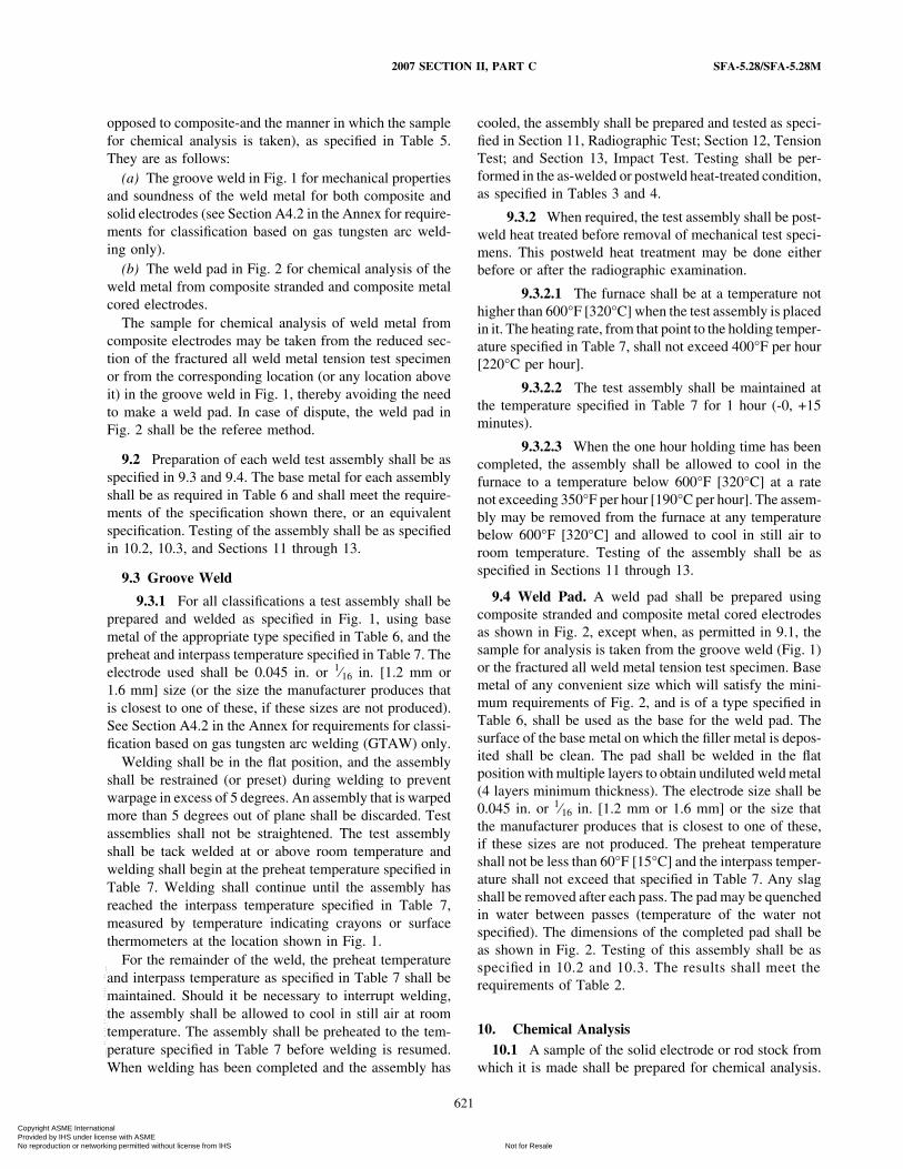
opposed to composite-and the manner in which the samplefor chemical analysis is taken), as specified in Table 5.They are as follows:
(a) The groove weld in Fig. 1 for mechanical propertiesand soundness of the weld metal for both composite andsolid electrodes (see Section A4.2 in the Annex for require-ments for classification based on gas tungsten arc weld-ing only).
(b) The weld pad in Fig. 2 for chemical analysis of theweld metal from composite stranded and composite metalcored electrodes.
The sample for chemical analysis of weld metal fromcomposite electrodes may be taken from the reduced sec-tion of the fractured all weld metal tension test specimenor from the corresponding location (or any location aboveit) in the groove weld in Fig. 1, thereby avoiding the needto make a weld pad. In case of dispute, the weld pad inFig. 2 shall be the referee method.
9.2 Preparation of each weld test assembly shall be asspecified in 9.3 and 9.4. The base metal for each assemblyshall be as required in Table 6 and shall meet the require-ments of the specification shown there, or an equivalentspecification. Testing of the assembly shall be as specifiedin 10.2, 10.3, and Sections 11 through 13.
9.3 Groove Weld
9.3.1 For all classifications a test assembly shall beprepared and welded as specified in Fig. 1, using basemetal of the appropriate type specified in Table 6, and thepreheat and interpass temperature specified in Table 7. Theelectrode used shall be 0.045 in. or 1⁄16 in. [1.2 mm or1.6 mm] size (or the size the manufacturer produces thatis closest to one of these, if these sizes are not produced).See Section A4.2 in the Annex for requirements for classi-fication based on gas tungsten arc welding (GTAW) only.
Welding shall be in the flat position, and the assemblyshall be restrained (or preset) during welding to preventwarpage in excess of 5 degrees. An assembly that is warpedmore than 5 degrees out of plane shall be discarded. Testassemblies shall not be straightened. The test assemblyshall be tack welded at or above room temperature andwelding shall begin at the preheat temperature specified inTable 7. Welding shall continue until the assembly hasreached the interpass temperature specified in Table 7,measured by temperature indicating crayons or surfacethermometers at the location shown in Fig. 1.
For the remainder of the weld, the preheat temperatureand interpass temperature as specified in Table 7 shall bemaintained. Should it be necessary to interrupt welding,the assembly shall be allowed to cool in still air at roomtemperature. The assembly shall be preheated to the tem-perature specified in Table 7 before welding is resumed.When welding has been completed and the assembly has
621
cooled, the assembly shall be prepared and tested as speci-fied in Section 11, Radiographic Test; Section 12, TensionTest; and Section 13, Impact Test. Testing shall be per-formed in the as-welded or postweld heat-treated condition,as specified in Tables 3 and 4.
9.3.2 When required, the test assembly shall be post-weld heat treated before removal of mechanical test speci-mens. This postweld heat treatment may be done eitherbefore or after the radiographic examination.
9.3.2.1 The furnace shall be at a temperature nothigher than 600°F [320°C] when the test assembly is placedin it. The heating rate, from that point to the holding temper-ature specified in Table 7, shall not exceed 400°F per hour[220°C per hour].
9.3.2.2 The test assembly shall be maintained atthe temperature specified in Table 7 for 1 hour (-0, +15minutes).
9.3.2.3 When the one hour holding time has beencompleted, the assembly shall be allowed to cool in thefurnace to a temperature below 600°F [320°C] at a ratenot exceeding 350°F per hour [190°C per hour]. The assem-bly may be removed from the furnace at any temperaturebelow 600°F [320°C] and allowed to cool in still air toroom temperature. Testing of the assembly shall be asspecified in Sections 11 through 13.
9.4 Weld Pad. A weld pad shall be prepared usingcomposite stranded and composite metal cored electrodesas shown in Fig. 2, except when, as permitted in 9.1, thesample for analysis is taken from the groove weld (Fig. 1)or the fractured all weld metal tension test specimen. Basemetal of any convenient size which will satisfy the mini-mum requirements of Fig. 2, and is of a type specified inTable 6, shall be used as the base for the weld pad. Thesurface of the base metal on which the filler metal is depos-ited shall be clean. The pad shall be welded in the flatposition with multiple layers to obtain undiluted weld metal(4 layers minimum thickness). The electrode size shall be0.045 in. or 1⁄16 in. [1.2 mm or 1.6 mm] or the size thatthe manufacturer produces that is closest to one of these,if these sizes are not produced. The preheat temperatureshall not be less than 60°F [15°C] and the interpass temper-ature shall not exceed that specified in Table 7. Any slagshall be removed after each pass. The pad may be quenchedin water between passes (temperature of the water notspecified). The dimensions of the completed pad shall beas shown in Fig. 2. Testing of this assembly shall be asspecified in 10.2 and 10.3. The results shall meet therequirements of Table 2.
10. Chemical Analysis10.1 A sample of the solid electrode or rod stock from
which it is made shall be prepared for chemical analysis.
Copyright ASME International Provided by IHS under license with ASME
Not for ResaleNo reproduction or networking permitted without license from IHS
--`,,```,,,,````-`-`,,`,,`,`,,`---

SFA-5.28/SFA-5.28M 2007 SECTION II, PART C
FIG. 1 GROOVE WELD TEST ASSEMBLY FOR MECHANICAL PROPERTIES AND SOUNDNESS
L1/2 lengthZ
Z
A
A
B
W
W
B
Impact specimens
Point of temperature measurement
P 45� � preset
Preset
X
R
T
VAll-weld-metal tension specimen
(a) Test Plate Showing Location of Test Specimens
(b) Groove Preparation of Test Plate
45�
(c) Orientation of
Impact SpecimenButtered test plate (see footnote “a” of Table 6)
Standard test plate(d) Location of All-Weld-Metal
Tension Specimen
C Specimen Center 3/8 9.5L Length, min. 10 250P Point of Temperature 1 25
MeasurementR Root Opening 1/2 13S Backup Strip Overlap, min. 1/4 6T Thickness 3/4 19V Backup Strip Thickness, min. 3/8 9W Width, min. 5 125X Backup Strip Width, min. 1 25Z Discard, min. 1 25
Dimensions
in. mm
Weld CL Weld
Section B-B
CL
S
C
Section A-A
45�
R R
T T
V
V
See Note (3)
1/8 [3]
1/8 [3]
Test Conditions for Solid Electrodes [Notes (4) and (5)]
Standard size [Note (7)] 0.045 in. [1.2 mm] 1⁄16 in. [1.6 mm]Shielding gas [Note (8)] See Table 3 See Table 3Wire feed speed 450 in./min. [190 mm/sec.] ±5% 240 in./min. [102 mm/sec.] ±5%Nominal arc voltage 27 to 32 V 25 to 30 VResulting current, DCEP [Note (9)]
300 to 360 A [Note (6)] 340 to 420 A [Note (6)](DCEP p electrode positive)
Contact-tip-to-work distance [Note (10)] 7⁄8 ± 1⁄8 in. [22 ± 3 mm] 7⁄8 ± 1⁄8 in. [22 ± 3 mm]Travel speed 13 ± 2 in./min. [5.5 ± 1.0 mm/sec.] 13 ± 2 in./min. [5.5 ± 1.0 mm/sec.]
NOTES:1. Base metal shall be as specified in Table 6. The surfaces to be welded shall be clean.2. Prior to welding, the assembly may be preset as shown so that the welded joint will be sufficiently flat to facilitate test specimen removal. As
an alternative, restraint or a combination of restraint and preset may be used.3. When required, edges of the grooves and the contacting face of the backing shall be buttered as shown. Any size of the electrode being tested
may be used for buttering. See Table 6, Note a.4. Test conditions for composite electrodes shall be as recommended by the manufacturer.5. Preheat and interpass temperatures for both solid and composite electrodes shall be as specified in Table 7.6. For ER80S-D2 [ER55S-D2] classification, the amperage range for 0.045 in. [1.2 mm] shall be 260 to 320 A and for 1/16 in. [1.6 mm],
330 to 410 A.7. If sizes other than 0.045 in. and 1/16 in. [1.2 mm and 1.6 mm] are tested, wire feed speed (and resulting current), arc voltage, and contact-
tip-to work distance shall be changed as needed. This joint configuration is not recommended for electrode sizes smaller than 0.035 in. [0.9 mm].8. If shielding gases or blends other than those shown in Table 3 are used, the wire feed speed (and resulting current), arc voltage, and travel
speed are to be as agreed to between purchaser and supplier.9. The required combination of electrode feed rate, arc voltage, and contact-tip-to-work distance should produce welding currents in the ranges
shown. Currents substantially outside these ranges suggest errors in feed rate, contact-tip-to-work distance, voltage settings, or in instrumentation.10. Distance from the contact tip to the work, not from the shielding gas cup to the work.
622
Copyright ASME International Provided by IHS under license with ASME
Not for ResaleNo reproduction or networking permitted without license from IHS
--`,,```,,,,````-`-`,,`,,`,`,,`---

2007 SECTION II, PART C SFA-5.28/SFA-5.28M
FIG. 2 PAD FOR CHEMICAL ANALYSIS OF WELD METAL FROM COMPOSITE ELECTRODES
Weld metal
H, height[See Note (8)]
L, length[See Note (8)]
Base metal
W, width[See Note (8)]
NOTES:1. Base metal of any convenient size, of the type specified in Table 6, shall be used as the base for the weld pad.2. The surface of the base metal on which the filler metal is to be deposited shall be clean.3. The pad shall be welded in the flat position with successive layers to obtain weld metal of sufficient height4. The number and size of the beads will vary according to the size of the electrode and the width of the weave, as well as with the amperage
employed.5. The preheat temperature shall not be less than 60°F [15°C] and the maximum interpass temperature shall not exceed that specified in Table 76. Any slag shall be removed after each pass.7. The test assembly may be quenched in water between passes to control interpass temperature.8. The minimum completed pad size shall be at least four layers in height (H). The sample for analysis shall be taken at least 3⁄8 in. [9.5 mm]
above the original base metal surface. The length (L), after allowance for start and stop areas, and width (W) shall be sufficient to performanalysis.
Solid filler metal, when analyzed for elements that arepresent in a coating (copper flashing, for example), shallbe analyzed without removing the coating. When the fillermetal is analyzed for elements other than those in thecoating, the coating shall be removed, if its presence affectsthe results of the analysis for the other elements.
10.2 Composite stranded or metal cored electrodes shallbe analyzed in the form of weld metal, not filler metal.The sample for analysis shall be taken from weld metalobtained with the electrode and the shielding gas as speci-fied in Table 3. The sample may be taken from the weldpad prepared in accordance with 9.4, from an area of thegroove weld as specified in 9.1, or from the reduced sectionof the fractured tension test specimen. In case of dispute,the weld pad is the referee method.The top surface of the pad described in 9.4 and shown inFig. 2 shall be removed and discarded. A sample for analy-sis shall be obtained from the underlying metal, no closerthan 3⁄8 in. [9.5 mm] to the surface of the base metal inFig. 2, by any appropriate mechanical means. The sampleshall be free of slag. When the sample is taken from thegroove weld or the reduced section of the fractured tensiontest specimen, that material shall be prepared for analysisby any suitable mechanical means.
623
10.3 The sample obtained as specified in 10.1 or 10.2shall be analyzed by accepted analytical methods. Thereferee method shall be ASTM E 350.
10.4 The results of the analysis shall meet the require-ments of Table 1 for solid electrodes or Table 2 for compos-ite electrodes for the classification of electrode under test.
11. Radiographic Test11.1 The groove weld described in 9.3.1 and shown in
Fig. 1 shall be radiographed to evaluate the soundness ofthe weld metal. In preparation for radiography, the backingshall be removed and both surfaces of the weld shall bemachined or ground smooth. It is permitted on both sidesof the test assembly to remove base metal to a depth of1⁄16 in. [1.5 mm] nominal below the original base metalsurface in order to facilitate backing and/or buildupremoval. Thickness of the weld metal shall not be reducedby more than 1⁄16 in. [1.5 mm] less than the nominal basemetal thickness. Both surfaces of the test assembly, in thearea of the weld, shall be smooth enough to avoid difficultyin interpreting the radiograph.
11.2 The weld shall be radiographed in accordancewith ASTM E 1032. The quality level of inspection shallbe 2-2T.
Copyright ASME International Provided by IHS under license with ASME
Not for ResaleNo reproduction or networking permitted without license from IHS
--`,,```,,,,````-`-`,,`,,`,`,,`---
SFA-5.28/SFA-5.28M 2007 SECTION II, PART C
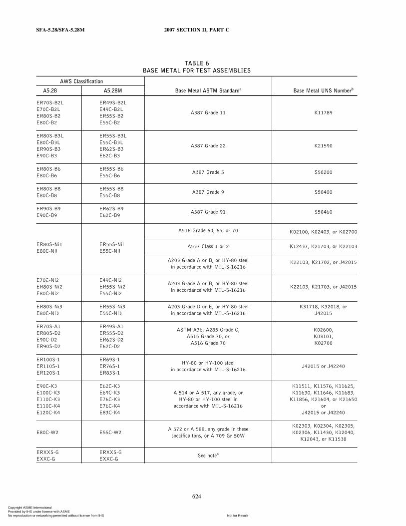
TABLE 6BASE METAL FOR TEST ASSEMBLIES
AWS Classification
A5.28 A5.28M Base Metal ASTM Standarda Base Metal UNS Numberb
ER70S-B2L ER49S-B2LE70C-B2L E49C-B2L
A387 Grade 11 K11789ER80S-B2 ER55S-B2E80C-B2 E55C-B2
ER80S-B3L ER55S-B3LE80C-B3L E55C-B3L
A387 Grade 22 K21590ER90S-B3 ER62S-B3E90C-B3 E62C-B3
ER80S-B6 ER55S-B6A387 Grade 5 S50200
E80C-B6 E55C-B6
ER80S-B8 ER55S-B8A387 Grade 9 S50400
E80C-B8 E55C-B8
ER90S-B9 ER62S-B9A387 Grade 91 S50460
E90C-B9 E62C-B9
A516 Grade 60, 65, or 70 K02100, K02403, or K02700
ER80S-Ni1 ER55S-Nil A537 Class 1 or 2 K12437, K21703, or K22103E80C-Nil E55C-Nil
A203 Grade A or B, or HY-80 steel K22103, K21702, or J42015in accordance with MIL-S-16216
E70C-Ni2 E49C-Ni2A203 Grade A or B, or HY-80 steel
ER80S-Ni2 ER55S-Ni2 K22103, K21703, or J42015in accordance with MIL-S-16216
E80C-Ni2 E55C-Ni2
ER80S-Ni3 ER55S-Ni3 A203 Grade D or E, or HY-80 steel K31718, K32018, orE80C-Ni3 E55C-Ni3 in accordance with MIL-S-16216 J42015
ER70S-A1 ER49S-A1ASTM A36, A285 Grade C, K02600,
ER80S-D2 ER55S-D2A515 Grade 70, or K03101,
E90C-D2 ER62S-D2A516 Grade 70 K02700
ER90S-D2 E62C-D2
ER100S-1 ER69S-1HY-80 or HY-100 steel
ER110S-1 ER76S-1 J42015 or J42240in accordance with MIL-S-16216
ER120S-1 ER83S-1
E90C-K3 E62C-K3 K11511, K11576, K11625,E100C-K3 E69C-K3 A 514 or A 517, any grade, or K11630, K11646, K11683,E110C-K3 E76C-K3 HY-80 or HY-100 steel in K11856, K21604, or K21650E110C-K4 E76C-K4 accordance with MIL-S-16216 orE120C-K4 E83C-K4 J42015 or J42240
K02303, K02304, K02305,A 572 or A 588, any grade in these
E80C-W2 E55C-W2 K02306, K11430, K12040,specificaitons, or A 709 Gr 50W
K12043, or K11538
ERXXS-G ERXXS-GSee notea
EXXC-G EXXC-G
624
Copyright ASME International Provided by IHS under license with ASME
Not for ResaleNo reproduction or networking permitted without license from IHS
--`,,```,,,,````-`-`,,`,,`,`,,`---

2007 SECTION II, PART C SFA-5.28/SFA-5.28M
TABLE 6BASE METAL FOR TEST ASSEMBLIES (CONT’D)
NOTES:a. For any weld metal classification in this specification, ASTM A 36, A 285 Grade C, A 515 Grade 70, or A 516 Grade 70 may be used. In
that case, the groove faces and the contacting face of the backing shall be buttered, as shown in Fig. 1, using the electrode being classifiedor an electrode of the same weld metal composition as that specified for the electrode being tested, or using an electrode of the specifiedcomposition classified in another AWS low-alloy steel filler metal specification. Weld pads for chemical analysis meeting minimum heightrequirements of Fig. 2 are not subject to additional buttering requirements. Alternately, for the indicated weld metal classification, thecorresponding base metals may be used for weld test assemblies without buttering. In case of dispute, buttered A 36 steel shall be the refereematerial.
b. SAE-HS-1086/ASTM DS-58H, Metals & Alloys in the Unified Numbering System.
TABLE 7PREHEAT, INTERPASS, AND POSTWELD HEAT TREATMENT TEMPERATURES
AWS Classification Preheat and Interpass Temperaturea PWHT Temperaturea
A5.28 A5.28M °F °C °F °C
ER70S-A1 ER49S-A1ER80S-B2 ER55S-B2E80C-B2 E55C-B2 275–325 135–165 1150 ± 25 620 ± 15ER70S-B2L ER49S-B2LE70C-B2L E49C-B2L
ER90S-B3 ER62S-B3E90C-B3 E62C-B3 375–425 185–215 1275 ± 25 690 ± 15ER80S-B3L ER55S-B3LE80C-B3L E55C-B3L
ER80S-B6 ER55S-B6 350–450 177–232 1375 ± 25 745 ± 15E80C-B6 E55C-B6
ER80S-B8 ER55S-B8 400–500 205–260 1375 ± 25 745 ± 15E80C-B8 E55C-B8
ER90S-B9 ER62S-B9 400–600 205–320 1400 ± 25c 760 ± 15c
E90C-B9 E62C-B9
E70C-Ni2 E49C-Ni2ER80S-Ni2 ER55S-Ni2E80C-Ni2 E55C-Ni2 275–325 135–165 1150 ± 25 620 ± 15ER80S-Ni3 ER55S-Ni3E80C-Ni3 E55C-Ni3
ER80S-D2 ER55S-D2ER90S-D2 ER62S-D2E90C-D2 E62C-D2ER80S-Ni1 ER55S-Ni1E80C-Ni1 E55C-Ni1ER100S-1 ER69S-1ER110S-1 ER76S-1 275–325 135–165 Noneb Noneb
ER120S-1 ER83S-1E90C-K3 E62C-K3E100C-K3 E69C-K3E110C-K3 E76C-K3E110C-K4 E76C-K4E120C-K4 E83C-K4E80C-W2 E55C-W2
ERXXXS-G ERXXXS-GConditions as agreed upon between supplier and purchaser
EXXC-G EXXC-G
NOTES:a. These temperatures are specified for testing under this specification and are not to be considered as recommendations for preheat, interpass,
and postweld heat treatment in production welding. The requirements for production welding must be determined by the user. They may ormay not differ from those called for here.
b. These classifications are normally used in the as-welded condition.c. Prior to PWHT, allow the weldment to cool in still air to below 200°F [100°C]. Hold at specific temperature for two hours.
625
07
Copyright ASME International Provided by IHS under license with ASME
Not for ResaleNo reproduction or networking permitted without license from IHS
--`,,```,,,,````-`-`,,`,,`,`,,`---
SFA-5.28/SFA-5.28M 2007 SECTION II, PART C
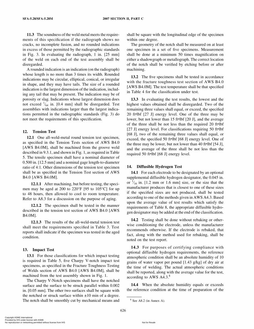
11.3 The soundness of the weld metal meets the require-ments of this specification if the radiograph shows nocracks, no incomplete fusion, and no rounded indicationsin excess of those permitted by the radiographic standardsin Fig. 3. In evaluating the radiograph, 1 in. [25 mm]of the weld on each end of the test assembly shall bedisregarded.
A rounded indication is an indication (on the radiograph)whose length is no more than 3 times its width. Roundedindications may be circular, elliptical, conical, or irregularin shape, and they may have tails. The size of a roundedindication is the largest dimension of the indication, includ-ing any tail that may be present. The indication may be ofporosity or slag. Indications whose largest dimension doesnot exceed 1⁄64 in. [0.4 mm] shall be disregarded. Testassemblies with indications larger than the largest indica-tions permitted in the radiographic standards (Fig. 3) donot meet the requirements of this specification.
12. Tension Test12.1 One all-weld-metal round tension test specimen,
as specified in the Tension Tests section of AWS B4.0[AWS B4.0M], shall be machined from the groove welddescribed in 9.3.1, and shown in Fig. 1, as required in Table5. The tensile specimen shall have a nominal diameter of0.500 in. [12.5 mm] and a nominal gage length-to-diameterratio of 4:1. Other dimensions of the tension test specimenshall be as specified in the Tension Test section of AWSB4.0 [AWS B4.0M].
12.1.1 After machining, but before testing, the speci-men may be aged at 200 to 220°F [95 to 105°C] for upto 48 hours, then allowed to cool to room temperature.Refer to A8.3 for a discussion on the purpose of aging.
12.1.2 The specimen shall be tested in the mannerdescribed in the tension test section of AWS B4.0 [AWSB4.0M].
12.1.3 The results of the all-weld-metal tension testshall meet the requirements specified in Table 3. Testreports shall indicate if the specimen was tested in the agedcondition.
13. Impact Test13.1 For those classifications for which impact testing
is required in Table 5, five Charpy V-notch impact testspecimens, as specified in the Fracture Toughness Testingof Welds section of AWS B4.0 [AWS B4.0M], shall bemachined from the test assembly shown in Fig. 1.
The Charpy V-Notch specimens shall have the notchedsurface and the surface to be struck parallel within 0.002in. [0.05 mm]. The other two surfaces shall be square withthe notched or struck surface within ±10 min of a degree.The notch shall be smoothly cut by mechanical means and
626
shall be square with the longitudinal edge of the specimenwithin one degree.
The geometry of the notch shall be measured on at leastone specimen in a set of five specimens. Measurementshall be done at a minimum 50 times magnification oneither a shadowgraph or metallograph. The correct locationof the notch shall be verified by etching before or aftermachining.
13.2 The five specimens shall be tested in accordancewith the fracture toughness test section of AWS B4.0[AWS B4.0M]. The test temperature shall be that specifiedin Table 4 for the classification under test.
13.3 In evaluating the test results, the lowest and thehighest values obtained shall be disregarded. Two of theremaining three values shall equal, or exceed, the specified20 ftWlbf [27 J] energy level. One of the three may belower, but not lower than 15 ftWlbf [20 J], and the averageof the three shall be not less than the required 20 ftWlbf[27 J] energy level. For classifications requiring 50 ftWlbf[68 J], two of the remaining three values shall equal, orexceed, the specified 50 ftWlbf [68 J] energy level. One ofthe three may be lower, but not lower than 40 ftWlbf [54 J],and the average of the three shall be not less than therequired 50 ftWlbf [68 J] energy level.
14. Diffusible Hydrogen Test14.1 For each electrode to be designated by an optional
supplemental diffusible hydrogen designator, the 0.045 in.or 1⁄16 in. [1.2 mm or 1.6 mm] size, or the size that themanufacturer produces that is closest to one of these sizesif the specified sizes are not produced, shall be testedaccording to one of the methods given in AWS A4.3. Basedupon the average value of test results which satisfy therequirements of Table 8, the appropriate diffusible hydro-gen designator may be added at the end of the classification.
14.2 Testing shall be done without rebaking or other-wise conditioning the electrode, unless the manufacturerrecommends otherwise. If the electrode is rebaked, thatfact, along with the method used for rebaking, shall benoted on the test report.
14.3 For purposes of certifying compliance withoptional diffusible hydrogen requirements, the referenceatmospheric condition shall be an absolute humidity of 10grains of water vapor per pound [1.43 g/kg] of dry air atthe time of welding. The actual atmospheric conditionsshall be reported, along with the average value for the test,according to AWS A4.3.8
14.4 When the absolute humidity equals or exceedsthe reference condition at the time of preparation of the
8 See A8.2 (in Annex A).
Copyright ASME International Provided by IHS under license with ASME
Not for ResaleNo reproduction or networking permitted without license from IHS
--`,,```,,,,````-`-`,,`,,`,`,,`---
2007 SECTION II, PART C SFA-5.28/SFA-5.28M
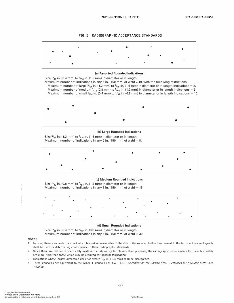
FIG. 3 RADIOGRAPHIC ACCEPTANCE STANDARDS
Size 1/64 in. (0.4 mm) to 1/16 in. (1.6 mm) in diameter or in length.Maximum number of indications in any 6 in. (150 mm) of weld = 18, with the following restrictions: Maximum number of large 3/64 in. (1.2 mm) to 1/16 in. (1.6 mm) in diameter or in length indications � 3. Maximum number of medium 1/32 (0.8 mm) to 3/64 in. (1.2 mm) in diameter or in length indications � 5. Maximum number of small 1/64 in. (0.4 mm) to 1/32 in. (0.8 mm) in diameter or in length indications � 10.
Size 3/64 in. (1.2 mm) to 1/16 in. (1.6 mm) in diameter or in length.Maximum number of indications in any 6 in. (150 mm) of weld � 8.
Size 1/32 in. (0.8 mm) to 3/64 in. (1.2 mm) in diameter or in length.Maximum number of indications in any 6 in. (150 mm) of weld � 15.
Size 1/64 in. (0.4 mm) to 1/32 in. (0.8 mm) in diameter or in length.Maximum number of indications in any 6 in. (150 mm) of weld � 30.
(a) Assorted Rounded Indications
(b) Large Rounded Indications
(c) Medium Rounded Indications
(d) Small Rounded Indications
NOTES:1. In using these standards, the chart which is most representative of the size of the rounded indications present in the test specimen radiograph
shall be used for determining conformance to these radiographic standards.2. Since these are test welds specifically made in the laboratory for classification purposes, the radiographic requirements for these test welds
are more rigid than those which may be required for general fabrication.3. Indications whose largest dimension does not exceed 1⁄64 in. [0.4 mm] shall be disregarded.4. These standards are equivalent to the Grade 1 standards of AWS A5.1, Specification for Carbon Steel Electrodes for Shielded Metal Arc
Welding.
627
Copyright ASME International Provided by IHS under license with ASME
Not for ResaleNo reproduction or networking permitted without license from IHS
--`,,```,,,,````-`-`,,`,,`,`,,`---
SFA-5.28/SFA-5.28M 2007 SECTION II, PART C
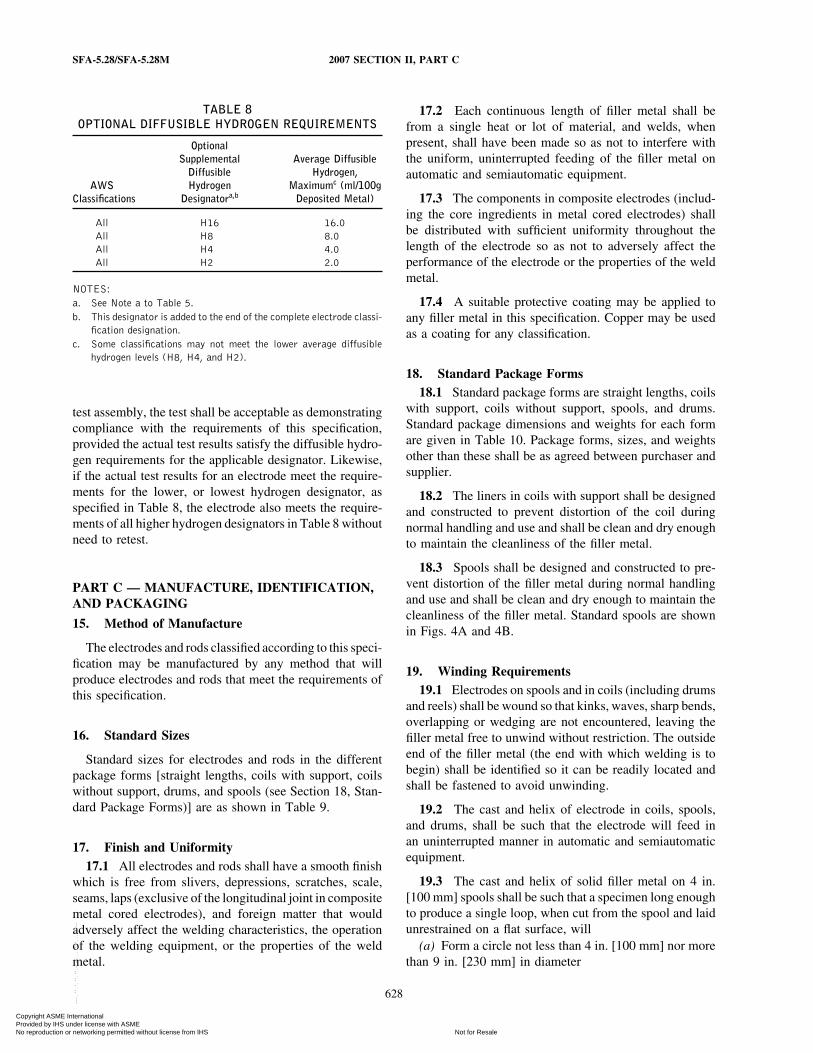
TABLE 8OPTIONAL DIFFUSIBLE HYDROGEN REQUIREMENTS
OptionalSupplemental Average Diffusible
Diffusible Hydrogen,AWS Hydrogen Maximumc (ml/100g
Classifications Designatora,b Deposited Metal)
All H16 16.0All H8 8.0All H4 4.0All H2 2.0
NOTES:a. See Note a to Table 5.b. This designator is added to the end of the complete electrode classi-
fication designation.c. Some classifications may not meet the lower average diffusible
hydrogen levels (H8, H4, and H2).
test assembly, the test shall be acceptable as demonstratingcompliance with the requirements of this specification,provided the actual test results satisfy the diffusible hydro-gen requirements for the applicable designator. Likewise,if the actual test results for an electrode meet the require-ments for the lower, or lowest hydrogen designator, asspecified in Table 8, the electrode also meets the require-ments of all higher hydrogen designators in Table 8 withoutneed to retest.
PART C — MANUFACTURE, IDENTIFICATION,AND PACKAGING
15. Method of Manufacture
The electrodes and rods classified according to this speci-fication may be manufactured by any method that willproduce electrodes and rods that meet the requirements ofthis specification.
16. Standard Sizes
Standard sizes for electrodes and rods in the differentpackage forms [straight lengths, coils with support, coilswithout support, drums, and spools (see Section 18, Stan-dard Package Forms)] are as shown in Table 9.
17. Finish and Uniformity17.1 All electrodes and rods shall have a smooth finish
which is free from slivers, depressions, scratches, scale,seams, laps (exclusive of the longitudinal joint in compositemetal cored electrodes), and foreign matter that wouldadversely affect the welding characteristics, the operationof the welding equipment, or the properties of the weldmetal.
628
17.2 Each continuous length of filler metal shall befrom a single heat or lot of material, and welds, whenpresent, shall have been made so as not to interfere withthe uniform, uninterrupted feeding of the filler metal onautomatic and semiautomatic equipment.
17.3 The components in composite electrodes (includ-ing the core ingredients in metal cored electrodes) shallbe distributed with sufficient uniformity throughout thelength of the electrode so as not to adversely affect theperformance of the electrode or the properties of the weldmetal.
17.4 A suitable protective coating may be applied toany filler metal in this specification. Copper may be usedas a coating for any classification.
18. Standard Package Forms18.1 Standard package forms are straight lengths, coils
with support, coils without support, spools, and drums.Standard package dimensions and weights for each formare given in Table 10. Package forms, sizes, and weightsother than these shall be as agreed between purchaser andsupplier.
18.2 The liners in coils with support shall be designedand constructed to prevent distortion of the coil duringnormal handling and use and shall be clean and dry enoughto maintain the cleanliness of the filler metal.
18.3 Spools shall be designed and constructed to pre-vent distortion of the filler metal during normal handlingand use and shall be clean and dry enough to maintain thecleanliness of the filler metal. Standard spools are shownin Figs. 4A and 4B.
19. Winding Requirements19.1 Electrodes on spools and in coils (including drums
and reels) shall be wound so that kinks, waves, sharp bends,overlapping or wedging are not encountered, leaving thefiller metal free to unwind without restriction. The outsideend of the filler metal (the end with which welding is tobegin) shall be identified so it can be readily located andshall be fastened to avoid unwinding.
19.2 The cast and helix of electrode in coils, spools,and drums, shall be such that the electrode will feed inan uninterrupted manner in automatic and semiautomaticequipment.
19.3 The cast and helix of solid filler metal on 4 in.[100 mm] spools shall be such that a specimen long enoughto produce a single loop, when cut from the spool and laidunrestrained on a flat surface, will
(a) Form a circle not less than 4 in. [100 mm] nor morethan 9 in. [230 mm] in diameter
Copyright ASME International Provided by IHS under license with ASME
Not for ResaleNo reproduction or networking permitted without license from IHS
--`,,```,,,,````-`-`,,`,,`,`,,`---
2007 SECTION II, PART C SFA-5.28/SFA-5.28M
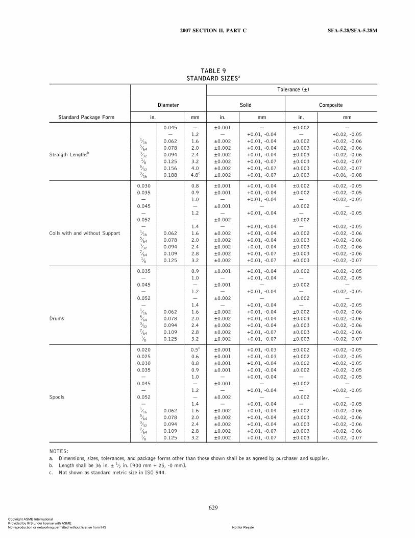
TABLE 9STANDARD SIZESa
Tolerance (±)
Diameter Solid Composite
Standard Package Form in. mm in. mm in. mm
0.045 — ±0.001 — ±0.002 —— 1.2 — +0.01, -0.04 — +0.02, -0.05
1⁄16 0.062 1.6 ±0.002 +0.01, -0.04 ±0.002 +0.02, -0.065⁄64 0.078 2.0 ±0.002 +0.01, -0.04 ±0.003 +0.02, -0.06
Straigth Lengthsb 3⁄32 0.094 2.4 ±0.002 +0.01, -0.04 ±0.003 +0.02, -0.061⁄8 0.125 3.2 ±0.002 +0.01, -0.07 ±0.003 +0.02, -0.07
5⁄32 0.156 4.0 ±0.002 +0.01, -0.07 ±0.003 +0.02, -0.073⁄16 0.188 4.8c ±0.002 +0.01, -0.07 ±0.003 +0.06, -0.08
0.030 0.8 ±0.001 +0.01, -0.04 ±0.002 +0.02, -0.050.035 0.9 ±0.001 +0.01, -0.04 ±0.002 +0.02, -0.05
— 1.0 — +0.01, -0.04 — +0.02, -0.050.045 — ±0.001 — ±0.002 —
— 1.2 — +0.01, -0.04 — +0.02, -0.050.052 — ±0.002 — ±0.002 —
— 1.4 — +0.01, -0.04 — +0.02, -0.05Coils with and without Support 1⁄16 0.062 1.6 ±0.002 +0.01, -0.04 ±0.002 +0.02, -0.06
5⁄64 0.078 2.0 ±0.002 +0.01, -0.04 ±0.003 +0.02, -0.063⁄32 0.094 2.4 ±0.002 +0.01, -0.04 ±0.003 +0.02, -0.067⁄64 0.109 2.8 ±0.002 +0.01, -0.07 ±0.003 +0.02, -0.061⁄8 0.125 3.2 ±0.002 +0.01, -0.07 ±0.003 +0.02, -0.07
0.035 0.9 ±0.001 +0.01, -0.04 ±0.002 +0.02, -0.05— 1.0 — +0.01, -0.04 — +0.02, -0.05
0.045 — ±0.001 — ±0.002 —— 1.2 — +0.01, -0.04 — +0.02, -0.05
0.052 — ±0.002 — ±0.002 —— 1.4 — +0.01, -0.04 — +0.02, -0.051⁄16 0.062 1.6 ±0.002 +0.01, -0.04 ±0.002 +0.02, -0.06
Drums 5⁄64 0.078 2.0 ±0.002 +0.01, -0.04 ±0.003 +0.02, -0.063⁄32 0.094 2.4 ±0.002 +0.01, -0.04 ±0.003 +0.02, -0.067⁄64 0.109 2.8 ±0.002 +0.01, -0.07 ±0.003 +0.02, -0.061⁄8 0.125 3.2 ±0.002 +0.01, -0.07 ±0.003 +0.02, -0.07
0.020 0.5c ±0.001 +0.01, -0.03 ±0.002 +0.02, -0.050.025 0.6 ±0.001 +0.01, -0.03 ±0.002 +0.02, -0.050.030 0.8 ±0.001 +0.01, -0.04 ±0.002 +0.02, -0.050.035 0.9 ±0.001 +0.01, -0.04 ±0.002 +0.02, -0.05
— 1.0 — +0.01, -0.04 — +0.02, -0.050.045 — ±0.001 — ±0.002 —
— 1.2 — +0.01, -0.04 — +0.02, -0.05Spools 0.052 — ±0.002 — ±0.002 —
— 1.4 — +0.01, -0.04 — +0.02, -0.051⁄16 0.062 1.6 ±0.002 +0.01, -0.04 ±0.002 +0.02, -0.065⁄64 0.078 2.0 ±0.002 +0.01, -0.04 ±0.003 +0.02, -0.063⁄32 0.094 2.4 ±0.002 +0.01, -0.04 ±0.003 +0.02, -0.067⁄64 0.109 2.8 ±0.002 +0.01, -0.07 ±0.003 +0.02, -0.061⁄8 0.125 3.2 ±0.002 +0.01, -0.07 ±0.003 +0.02, -0.07
NOTES:a. Dimensions, sizes, tolerances, and package forms other than those shown shall be as agreed by purchaser and supplier.b. Length shall be 36 in. ± 1⁄2 in. [900 mm + 25, -0 mm].c. Not shown as standard metric size in ISO 544.
629
Copyright ASME International Provided by IHS under license with ASME
Not for ResaleNo reproduction or networking permitted without license from IHS
--`,,```,,,,````-`-`,,`,,`,`,,`---
SFA-5.28/SFA-5.28M 2007 SECTION II, PART C
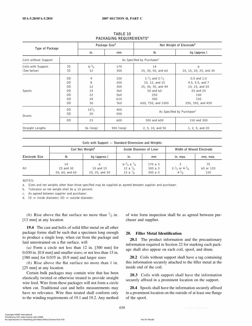
TABLE 10PACKAGING REQUIREMENTSa
Package Sized Net Weight of Electrodeb
Type of Packagein. mm lb kg (approx.)
Coils without Support As Specified by Purchaserc
Coils with Support ID 6-3⁄4 170 14 6(See below) ID 12 300 25, 30, 50, and 60 10, 15, 20, 25, and 30
OD 4 100 1-1⁄2 and 2-1⁄2 0.5 and 1.0OD 8 200 10, 12, and 15 4.5, 5.5, and 7OD 12 300 25, 30, 35, and 44 10, 15, and 20
Spools OD 14 360 50 and 60 20 and 25OD 22 560 250 100OD 24 610 300 150OD 30 760 600, 750, and 1000 250, 350, and 450
OD 151⁄2 400As Specified by Purchaserc
DrumsOD 20 500
OD 23 600 300 and 600 150 and 300
Straight Lengths 36 (long) 900 (long) 2, 5, 10, and 50 1, 2, 5, and 20
Coils with Support — Standard Dimensions and Weights
Coil Net Weightb Inside Diameter of Liner Width of Wound Electrode
Electrode Size lb kg (approx.) in. mm in. max. mm, max.
14 6 6-3⁄4 ± 1⁄8 170 ± 3 3 75All 25 and 30 10 and 15 12 ± 1⁄8 300 ± 3 2-1⁄2 or 4-5⁄8 65 or 120
50, 60, and 65 20, 25, and 30 12 ± 1⁄8 300 ± 3 4-5⁄8 120
NOTES:a. Sizes and net weights other than those specified may be supplied as agreed between supplier and purchaser.b. Tolerance on net weight shall be ± 10 percent.c. As agreed between supplier and purchaser.d. ID p inside diameter; OD p outside diameter.
(b) Rise above the flat surface no more than 1⁄2 in.[13 mm] at any location
19.4 The cast and helix of solid filler metal on all otherpackage forms shall be such that a specimen long enoughto produce a single loop, when cut from the package andlaid unrestrained on a flat surface, will
(a) Form a circle not less than 12 in. [300 mm] for0.030 in. [0.8 mm] and smaller sizes; or not less than 15 in.[380 mm] for 0.035 in. [0.9 mm] and larger sizes
(b) Rise above the flat surface no more than 1 in.[25 mm] at any location
Certain bulk packages may contain wire that has beenelastically twisted or otherwise treated to provide straightwire feed. Wire from these packages will not form a circlewhen cut. Traditional cast and helix measurements mayhave no relevance. Wire thus treated shall conform onlyto the winding requirements of 19.1 and 19.2. Any method
630
of wire form inspection shall be as agreed between pur-chaser and supplier.
20. Filler Metal Identification
20.1 The product information and the precautionaryinformation required in Section 22 for marking each pack-age shall also appear on each coil, spool, and drum.
20.2 Coils without support shall have a tag containingthis information securely attached to the filler metal at theinside end of the coil.
20.3 Coils with support shall have the informationsecurely affixed in a prominent location on the support.
20.4 Spools shall have the information securely affixedin a prominent location on the outside of at least one flangeof the spool.
Copyright ASME International Provided by IHS under license with ASME
Not for ResaleNo reproduction or networking permitted without license from IHS
--`,,```,,,,````-`-`,,`,,`,`,,`---
2007 SECTION II, PART C SFA-5.28/SFA-5.28M
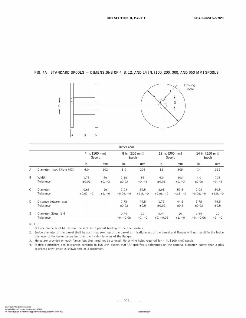
FIG. 4A STANDARD SPOOLS — DIMENSIONS OF 4, 8, 12, AND 14 IN. [100, 200, 300, AND 350 MM] SPOOLS
C
B
A
E
D
Driving hole
Dimensions
4 in. [100 mm] 8 in. [200 mm] 12 in. [300 mm] 14 in. [350 mm]Spools Spools Spools Spools
in. mm in. mm in. mm in. mm
A Diameter, max. [Note (4)] 4.0 102 8.0 203 12 305 14 355
B Width 1.75 46 2.16 56 4.0 103 4.0 103Tolerance ±0.03 +0, −2 ±0.03 +0, −3 ±0.06 +0, −3 ±0.06 +0, −3
C Diameter 0.63 16 2.03 50.5 2.03 50.5 2.03 50.5Tolerance +0.01, −0 +1, −0 +0.06, −0 +2.5, −0 +0.06, −0 +2.5, −0 +0.06, −0 +2.5, −0
D Distance between axes — — 1.75 44.5 1.75 44.5 1.75 44.5Tolerance ±0.02 ±0.5 ±0.02 ±0.5 ±0.02 ±0.5
E Diameter [Note (3)] — — 0.44 10 0.44 10 0.44 10Tolerance +0, −0.06 +1, −0 +0, −0.06 +1, −0 +0, −0.06 +1, −0
NOTES:1. Outside diameter of barrel shall be such as to permit feeding of the filler metals.2. Inside diameter of the barrel shall be such that swelling of the barrel or misalignment of the barrel and flanges will not result in the inside
diameter of the barrel being less than the inside diameter of the flanges.3. Holes are provided on each flange, but they need not be aligned. No driving holes required for 4 in. [100 mm] spools.4. Metric dimensions and tolerances conform to ISO 544 except that "A" specifies ± tolerances on the nominal diameter, rather than a plus
tolerance only, which is shown here as a maximum.
631
Copyright ASME International Provided by IHS under license with ASME
Not for ResaleNo reproduction or networking permitted without license from IHS
--`,,```,,,,````-`-`,,`,,`,`,,`---

SFA-5.28/SFA-5.28M 2007 SECTION II, PART C
FIG. 4B STANDARD SPOOLS — DIMENSIONS OF 22, 24, AND 30 IN. [560, 610, AND 760 MM] SPOOLS
A C
F
B
Section A–AA
E
D
A
Dimensions
22 in. [560 mm] Spools 24 in. [610 mm] Spools 30 in. [760 mm] Spools
in. mm in. mm in. mm
A Diameter, max. 22 560 24 610 30 760
B Width, max. 12 305 13.5 345 13.5 345
C Diameter 1.31 35.0 1.31 35.0 1.31 35.0Tolerance +0.13, −0 ±1.5 +0.13, −0 ±1.5 +0.13, −0 ±1.5
D Distance, Center-to-Center 2.5 63.5 2.5 63.5 2.5 63.5Tolerance ±0.1 ±1.5 ±0.1 ±1.5 ±0.1 ±1.5
E Diameter [Note (3)] 0.69 16.7 0.69 16.7 0.69 16.7Tolerance +0, −0.06 ±0.7 +0, −0.06 ±0.7 +0, −0.06 ±0.7
GENERAL NOTES:1. Outside diameter of barrel, dimension F, shall be such as to permit proper feeding of the electrode.2. Inside diameter of barrel shall be such that swelling of the barrel or misalignment of the barrel and flanges will not result in the inside of the
diameter of the barrel being less than the indside diameter of the flanges.3. Two holes are provided on each flange and shall be aligned on both flanges with the center hole.
632
Copyright ASME International Provided by IHS under license with ASME
Not for ResaleNo reproduction or networking permitted without license from IHS
--`,,```,,,,````-`-`,,`,,`,`,,`---

2007 SECTION II, PART C SFA-5.28/SFA-5.28M
20.5 Drums shall have the information securely affixedin a prominent location on the side of the drum.
21. Packaging
Electrodes and rods shall be suitably packaged to ensureagainst damage during shipment and storage under normalconditions.
22. Marking of Packages22.1 The following product information (as a mini-
mum) shall be legibly marked so as to be visible from theoutside of each unit package:
633
(a) AWS specification (year of issue may be excluded)and AWS classification numbers, along with any optionalsupplemental designators, if applicable
(b) Supplier’s name and trade designation(c) Size and net weight (see 1.3)(d) Lot, control, or heat number
22.2 The appropriate precautionary information9 givenin ANSI Z49.1, latest edition (as a minimum), shall beprominently displayed in legible print on all packages,including individual unit packages within a larger package.
9 Typical examples of “warning labels” are shown in figures in ANSIZ49.1 for some common or specific consumables used with certain pro-cesses.
Copyright ASME International Provided by IHS under license with ASME
Not for ResaleNo reproduction or networking permitted without license from IHS
--`,,```,,,,````-`-`,,`,,`,`,,`---

SFA-5.28/SFA-5.28M 2007 SECTION II, PART C
Annex AGuide to AWS Specification for Low-Alloy Steel Electrodes
and Rods for Gas Shielded Arc Welding(This Annex is not a part of AWS A5.28/A5.28M:2005, Specification for Low-Alloy Steel Electrodes and Rods for Gas Shielded Arc Welding, but
is included for informational purposes only.)
A1. Introduction
The purpose of this guide is to correlate the electrodeand rod classifications with their intended applications sothe specification can be used effectively. Reference toappropriate base metal specifications is made wheneverthat can be done and when it would be helpful. Suchreferences are intended only as examples rather than com-plete listings of the materials for which each filler metalis suitable.
A2. Classification System
A2.1 The system for identifying the electrode classifi-cations in this specification follows the standard patternused in other AWS filler metal specifications as shown inFig. A1.
A2.2 The prefix “E” designates an electrode as in otherspecifications. The letters “ER” indicate that the filler metalmay be used either as an electrode or a rod. For A5.28, thenumber 70, for example, indicates the required minimumtensile strength, as a multiple of 1000 psi, of the weldmetal in a test weld made in accordance with specificationA5.28. Similarly, for A5.28M, the number 49, for example,indicates the required minimum tensile strength, as a multi-ple of 10 MPa, of the weld metal in a test weld made inaccordance with specification A5.28M.
The letter “S” designates a solid electrode or rod.The letter “C” designates a composite electrode The
suffix following the hyphen indicates the chemical compo-sition of the filler metal itself, in the case of solid electrodesand rods, or the weld metal under certain specified testconditions, in the case of composite stranded or metal coredelectrodes.
Optional designators are also used in this specificationin order to identify electrodes and rods that have met man-datory classification requirements and certain supplemen-tary requirements as agreed to between the supplier andpurchaser. An optional supplemental diffusible hydrogendesignator (H16, H8, H4, or H2) may follow the classifica-tion designation, indicating whether the electrode will meet
634
a maximum hydrogen level of 16, 8, 4, or 2 mL/100g ofweld metal when tested as outlined in AWS A4.3. Elec-trodes that are designated as meeting the lower or lowesthydrogen limits, as specified in Table 8, are also understoodto be able to meet any higher hydrogen limits withoutnecessarily being designated as such.
A2.3 “G” ClassificationA2.3.1 These specifications include filler metals clas-
sified as ER80S-G [ER55S-G], E80C-G [E55C-G], etc.The “G” indicates that the filler metal is of a “general”classification. It is general because not all of the particularrequirements specified for each of the other classificationsare specified for this classification. The intent in establish-ing these classifications is to provide a means by whichfiller metals that differ in one respect or another (chemicalcomposition, for example) from all other classifications(meaning that the composition of the filler metal, in the caseof the example, does not meet the composition specified forany of the classifications in the specification) can still beclassified according to the specification. The purpose is toallow a useful filler metal-one that otherwise would haveto await a revision of the specification-to be classifiedimmediately under the existing specification. This means,then, that two filler metals, each bearing the same “G”classification, may be quite different in some particularrespect (chemical composition, again, for example).
A2.3.2 The point of difference (although not neces-sarily the amount of the difference) referred to above willbe readily apparent from the use of the words “not required”and “not specified” in the specification. The use of thesewords is as follows:
(a) “Not Specified” is used in those areas of the specifi-cation that refer to the results of some particular test. Itindicates that the requirements for that test are not specifiedfor that particular classification.
(b) “Not Required” is used in those areas of the specifi-cation that refer to the tests that must be conducted in orderto classify a filler metal. It indicates that the test is notrequired because the requirements (results) for the test havenot been specified for that particular classification.
Copyright ASME International Provided by IHS under license with ASME
Not for ResaleNo reproduction or networking permitted without license from IHS
--`,,```,,,,````-`-`,,`,,`,`,,`---
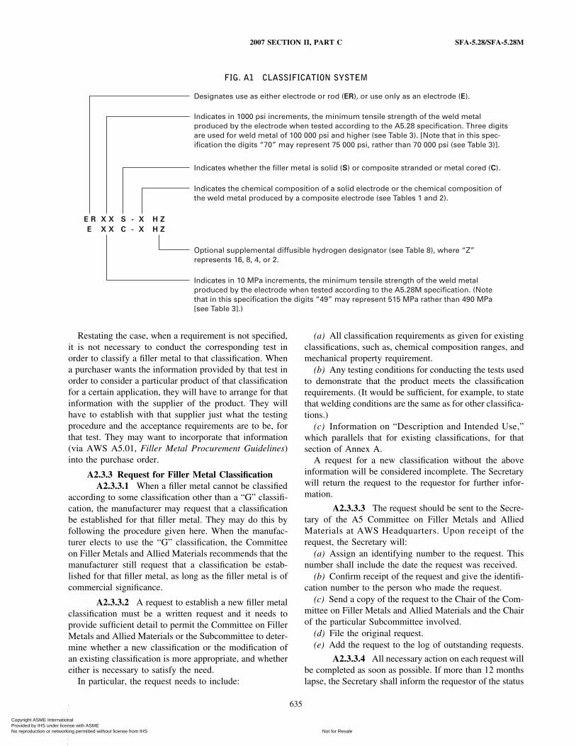
2007 SECTION II, PART C SFA-5.28/SFA-5.28M
FIG. A1 CLASSIFICATION SYSTEM
E R X X S X H Z-
E X X C X H Z-
Designates use as either electrode or rod (ER), or use only as an electrode (E).
Indicates whether the filler metal is solid (S) or composite stranded or metal cored (C).
Indicates the chemical composition of a solid electrode or the chemical composition ofthe weld metal produced by a composite electrode (see Tables 1 and 2).
Optional supplemental diffusible hydrogen designator (see Table 8), where “Z”represents 16, 8, 4, or 2.
Indicates in 10 MPa increments, the minimum tensile strength of the weld metalproduced by the electrode when tested according to the A5.28M specification. (Notethat in this specification the digits “49” may represent 515 MPa rather than 490 MPa[see Table 3].)
Indicates in 1000 psi increments, the minimum tensile strength of the weld metalproduced by the electrode when tested according to the A5.28 specification. Three digitsare used for weld metal of 100 000 psi and higher (see Table 3). [Note that in this spec-ification the digits “70” may represent 75 000 psi, rather than 70 000 psi (see Table 3)].
Restating the case, when a requirement is not specified,it is not necessary to conduct the corresponding test inorder to classify a filler metal to that classification. Whena purchaser wants the information provided by that test inorder to consider a particular product of that classificationfor a certain application, they will have to arrange for thatinformation with the supplier of the product. They willhave to establish with that supplier just what the testingprocedure and the acceptance requirements are to be, forthat test. They may want to incorporate that information(via AWS A5.01, Filler Metal Procurement Guidelines)into the purchase order.
A2.3.3 Request for Filler Metal ClassificationA2.3.3.1 When a filler metal cannot be classified
according to some classification other than a “G” classifi-cation, the manufacturer may request that a classificationbe established for that filler metal. They may do this byfollowing the procedure given here. When the manufac-turer elects to use the “G” classification, the Committeeon Filler Metals and Allied Materials recommends that themanufacturer still request that a classification be estab-lished for that filler metal, as long as the filler metal is ofcommercial significance.
A2.3.3.2 A request to establish a new filler metalclassification must be a written request and it needs toprovide sufficient detail to permit the Committee on FillerMetals and Allied Materials or the Subcommittee to deter-mine whether a new classification or the modification ofan existing classification is more appropriate, and whethereither is necessary to satisfy the need.
In particular, the request needs to include:
635
(a) All classification requirements as given for existingclassifications, such as, chemical composition ranges, andmechanical property requirement.
(b) Any testing conditions for conducting the tests usedto demonstrate that the product meets the classificationrequirements. (It would be sufficient, for example, to statethat welding conditions are the same as for other classifica-tions.)
(c) Information on “Description and Intended Use,”which parallels that for existing classifications, for thatsection of Annex A.
A request for a new classification without the aboveinformation will be considered incomplete. The Secretarywill return the request to the requestor for further infor-mation.
A2.3.3.3 The request should be sent to the Secre-tary of the A5 Committee on Filler Metals and AlliedMaterials at AWS Headquarters. Upon receipt of therequest, the Secretary will:
(a) Assign an identifying number to the request. Thisnumber shall include the date the request was received.
(b) Confirm receipt of the request and give the identifi-cation number to the person who made the request.
(c) Send a copy of the request to the Chair of the Com-mittee on Filler Metals and Allied Materials and the Chairof the particular Subcommittee involved.
(d) File the original request.(e) Add the request to the log of outstanding requests.
A2.3.3.4 All necessary action on each request willbe completed as soon as possible. If more than 12 monthslapse, the Secretary shall inform the requestor of the status
Copyright ASME International Provided by IHS under license with ASME
Not for ResaleNo reproduction or networking permitted without license from IHS
--`,,```,,,,````-`-`,,`,,`,`,,`---

SFA-5.28/SFA-5.28M 2007 SECTION II, PART C
of the request, with copies to the Chairs of the Committeeand of the Subcommittee. Requests still outstanding after18 months shall be considered not to have been answeredin a “timely manner” and the Secretary shall report theseto the Chair of the Committee on Filler Metals and AlliedMaterials, for action.
A2.3.3.5 The Secretary shall include a copy ofthe log of all requests pending and those completed duringthe preceding year with the agenda for each Committeeon Filler Metals and Allied Materials meeting. Any otherpublication of requests that have been completed will beat the option of the American Welding Society, as deemedappropriate.
A3. Acceptance
Acceptance of all welding materials classified under thisspecification is in accordance with AWS A5.01, FillerMetal Procurement Guidelines, as the Specification states.Any testing a purchaser requires of the supplier, for mate-rial shipped in accordance with this specification, shallbe clearly stated in the purchase order, according to theprovisions of AWS A5.01. In the absence of any suchstatement in the purchase order, the supplier may ship thematerial with whatever testing is normally conducted onmaterial of that classification, as specified in Schedule F,Table 1, of AWS A5.01. Testing in accordance with anyother schedule in that table must be specifically requiredby the purchase order. In such cases, acceptance of thematerial shipped will be in accordance with those require-ments.
A4. CertificationA4.1 The act of placing the AWS specification and
classification designations and optional supplemental des-ignators, if applicable, on the packaging enclosing the prod-uct, or the classification on the product itself, constitutes thesupplier’s (manufacturer’s) certification that the productmeets all of the requirements of the specification.
The only testing requirement implicit in this “certifica-tion” is that the manufacturer has actually conducted thetests required by the specification on material that is repre-sentative of that being shipped, and that the material metthe requirements of the specification. Representative mate-rial, in this case, is any production run of that classificationusing the same formulation. “Certification” is not to beconstrued to mean that tests of any kind were necessarilyconducted on samples of the specific material shipped.Tests on such material may or may not have been con-ducted. The basis for the certification required by the speci-fication is the classification test of “representative material”cited above, and the “Manufacturer’s Quality AssuranceSystem” in AWS A5.01, Filler Metal Procurement Guide-lines.
636
A4.2 (Optional) At the option and expense of the pur-chaser, acceptance may be based on the results of any orall of the tests required by this specification made on theGTAW test assembly described in Fig. A2.
One all-weld-metal round tension test specimen, as spec-ified in the Tension Tests section of AWS B4.0 [AWSB4.0M], Standard Methods for Mechanical Testing ofWelds, shall be machined from the groove weld describedin Fig. A2. The tensile specimen shall have a nominaldiameter of 0.350 in. [9.0 mm] and a nominal gage length-to-diameter ratio of 4:1. The specimen shall be tested asspecified in Section 12.1. Other dimensions of the tensiontest specimen shall be as specified in the Tension Testsection of AWS B4.0 [AWS B4.0M].
The Charpy V-Notch specimens shall be as specified inSection 13. Composite electrodes are normally not recom-mended for GTAW or PAW.
A5. Ventilation During Welding
A5.1 Five major factors govern the quantity of fumesin the atmosphere to which welders and welding operatorsare exposed during welding:
(a) Dimensions of the space in which welding is done(with special regard to the height of the ceiling)
(b) Number of welders and welding operators workingin that space
(c) Rate of evolution of fumes, gases, or dust, accordingto the materials and processes used
(d) The proximity of the welders or welding operatorsto the fumes as the fumes issue from the welding zone,and to the gases and dusts in the space in which they areworking
(e) The ventilation provided to the space in which thewelding is done
A5.2 American National Standard Z49.1, Safety inWelding, Cutting, and Allied Processes (published by theAmerican Welding Society), discusses the ventilation thatis required during welding and should be referred to fordetails. Attention is drawn particularly to the Section onHealth Protection and Ventilation in that document.
A6. Welding Considerations
A6.1 Gas metal arc welding (GMAW) can be dividedinto three categories based on the mode of metal transfer.These modes are (1) spray (conventional or pulsed), (2)globular, and (3) short circuiting transfer. In the spray,pulsed spray, and globular modes, transfer occurs as dis-tinct droplets that are detached from the electrode, transfer-ring along the arc column into the weld pool. In the shortcircuiting mode, the metal is deposited during frequentshort circuiting of the electrode in the molten pool.
Copyright ASME International Provided by IHS under license with ASME
Not for ResaleNo reproduction or networking permitted without license from IHS
--`,,```,,,,````-`-`,,`,,`,`,,`---
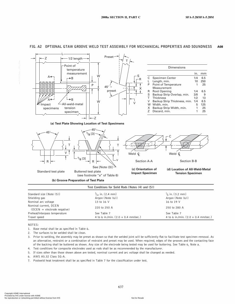
2008a SECTION II, PART C SFA-5.28/SFA-5.28M
FIG. A2 OPTIONAL GTAW GROOVE WELD TEST ASSEMBLY FOR MECHANICAL PROPERTIES AND SOUNDNESS
L1/2 lengthZ
Z
A
A
B
W
W
B
Impact specimens
Point of temperature measurement
P 45� � preset
Preset
X
R
T
VAll-weld-metal tension specimen
(a) Test Plate Showing Location of Test Specimens
(b) Groove Preparation of Test Plate
45�
(c) Orientation of
Impact SpecimenButtered test plate (see footnote “a” of Table 6)
Standard test plate(d) Location of All-Weld-Metal
Tension Specimen
C Specimen Center 1/4 6.5L Length, min. 10 250P Point of Temperature 1 25
MeasurementR Root Opening 1/4 6.5S Backup Strip Overlap, min. 3/8 9T Thickness 1/2 13V Backup Strip Thickness, min. 1/4 6.5W Width, min. 5 125X Backup Strip Width, min. 1 25Z Discard, min. 1 25
Dimensions
in. mm
Weld CL Weld
Section B-B
CL
S
C
Section A-A
45�
R R
T T
V
V
See [Note (3)]
1/8 [3]
1/8 [3]
Test Conditions for Solid Rods [Notes (4) and (5)]
Standard size [Note (5)] 3⁄32 in. [2.4 mm] 1⁄8 in. [3.2 mm]Shielding gas Argon [Note (6)] Argon [Note (6)]Nominal arc voltage 13 to 16 V 16 to 19 VNominal current, DCEN
220 to 250 A 250 to 280 A(DCEN p electrode negative)
Preheat/interpass temperature See Table 7 See Table 7Travel speed 4 to 6 in./min. [2.0 + 0.4 mm/sec.] 4 to 6 in./min. [2.0 + 0.4 mm/sec.]
NOTES:1. Base metal shall be as specified in Table 6.2. The surfaces to be welded shall be clean.3. Prior to welding, the assembly may be preset as shown so that the welded joint will be sufficiently flat to facilitate test specimen removal. As
an alternative, restraint or a combination of restraint and preset may be used. When required, edges of the grooves and the contacting faceof the backing shall be buttered as shown. Any size of the electrode being tested may be used for buttering. See Table 6, Note a.
4. Test conditions for composite electrodes used as rods shall be as recommended by the manufacturer.5. If sizes other than those shown above are tested, nominal current and arc voltage shall be changed as needed.6. AWS A5.32 Class SG-A.7. Postweld heat treatment shall be as specified in Table 7 for the classification under test.
637
A08
Copyright ASME International Provided by IHS under license with ASME
Not for ResaleNo reproduction or networking permitted without license from IHS
--`,,```,,,,````-`-`,,`,,`,`,,`---
SFA-5.28/SFA-5.28M 2008a SECTION II, PART C
A6.2 Spray Transfer
A6.2.1 The spray transfer mode, for carbon steel, ismost commonly obtained with argon shielding gas mix-tures with up to 5% of oxygen (AWS A5.32 Class SG-AO-X, where X is 1 to 5) or up to 15% carbon dioxide(AWS A5.32 Class SG-AC-Y, where Y is 5 to 15). Acharacteristic of these shielding gas mixtures is the smootharc plasma through which hundreds of very fine dropletsare transferred to the weld pool each second.
A6.2.2 Spray transfer with argon-oxygen (AWSA5.32 Class SG-AO-X) or argon-carbon dioxide (AWSA5.32 Class SG-AC-Y) shielding gas is, primarily, a func-tion of current density, polarity, and resistance heating ofthe electrode. The high droplet rate (approximately 250droplets per second) develops suddenly above a criticalcurrent level, commonly referred to as the transition current(for each size of electrode). Below this current, the metalis transferred in drops generally larger in diameter thanthe electrode and at a rate of from 10 to 20 per second(globular transfer). The transition current is also dependent,to some extent, on the chemical composition of the elec-trode. For 1⁄16 in. [1.6 mm] diameter carbon steel electrodes,a transition current of 270 amperes (direct current, elec-trode positive [dcep]) is common. Alternating current isnot recommended for this type of welding because it doesnot produce a stable arc.
A6.2.3 Pulsed Spray. Metal transfer in pulsed spraywelding is similar to that of the spray transfer describedabove, but it occurs at a lower average current. The loweraverage current is made possible by rapid pulsing of thewelding current between a high level, where metal willtransfer rapidly in the spray mode, and a low level, whereno transfer will take place. At a typical rate of 60 to 120pulses per second, a melted drop is formed by the lowcurrent arc, which is then “squeezed off” by the high currentpulse. This permits all-position welding.
A6.3 Globular Transfer. The mode of transfer thatcharacterizes 100% CO2 (AWS A5.32 Class SG-C) as ashielding gas is globular. Common practice with globulartransfer is to use low arc voltage to minimize spatter. Thisshortens the arc length causing the arc to be “buried” andresults in deeper penetration and better containment ofspatter within the weld pool. Electrodes of 0.045 in. through1⁄16 in. [0.2 mm through 1.6 mm] diameter normally areused at welding currents in the range of 275 to 400 amperes(dcep), for this type of transfer. The rate at which droplets(globules) are transferred ranges from 20 to 70 per second,depending on the size of the electrode, the amperage, polar-ity, and arc voltage.
A6.4 Short Circuiting Transfer. This mode of transferis obtained with small diameter electrodes (0.030 to0.045 in. [0.8 to 1.2 mm]) using low arc voltages and
638
amperages, and a power source designed for short circuit-ing transfer. The electrode short-circuits to the weld metal,usually at a rate of from 50 to 200 times per second. Metalis transferred with each short circuit, but not across thearc. Short circuiting gas metal arc welding of carbon steelis done most commonly with mixtures of argon and CO2
(AWS A5.32 Class SG-AC-Y) as the shielding gas or withCO2 (AWS A5.32 Class SG-C) alone. The penetration ofsuch welds is greater with CO2 than it is with argon-CO2
mixtures. Mixtures of 50% to 80% argon with CO2 remain-der (AWS A5.32 Class SG-AC-Y, where Y is 20 to 50)can be advantageous for thin material. However shieldinggas mixtures of 50% to 70% argon with CO2 remainder(AWS A5.32 Class SG-AC-Y, where Y is 30 to 50) areunstable in the gaseous state and must be mixed fromsingle gas components immediately prior to use. Theyprovide low penetration, higher short circuiting rates, andlower minimum currents and voltages than CO2 alone does.This can be an advantage in welding thin plate.
Regardless of gas used, the total heat input limits fusionand penetration. Therefore, many users limit this processto material thickness not exceeding 1⁄2 in. [13 mm].
A7. Description and Intended Use of Electrodes andRods
A7.1 The following is a description of the characteris-tics and intended use of the filler metals classified by thisspecification. The designations and the chemical composi-tion requirements for all classifications are given in Tables1 and 2 of this specification. The mechanical properties ofweld metals from filler metals of the various classificationswill conform to the minimum requirements stated in Tables3 and 4 of the specification.
A7.2 It should be noted that weld properties may varyappreciably depending on filler metal size and current used,plate thickness, joint geometry, preheat and inter-pass tem-peratures, surface conditions, base-metal composition andextent of alloying with the filler metal, and shielding gas.For example, when filler metals having an analysis withinthe range of Table 1 are deposited, the weld metal chemicalcomposition will not vary greatly from the as-manufacturedcomposition of the filler metal when used with argon-oxygen shielding gas. However, they will show a consider-able reduction in the content of manganese, silicon, andother deoxidizers when used with CO2 as the shielding gas.
A7.3 ER70S-A1 [ER49S-A1] Classification (1⁄2 Mo).Filler metal of this classification is similar to many of thecarbon steel filler metals classified in AWS A5.18/A5.18M,except that 0.5 percent molybdenum has been added. Thisaddition increases the strength of the weld metal, especiallyat elevated temperatures, and provides some increase incorrosion resistance; however, it will likely reduce thenotch toughness of the weld metal. Typical applications
Copyright ASME International Provided by IHS under license with ASME
Not for ResaleNo reproduction or networking permitted without license from IHS
--`,,```,,,,````-`-`,,`,,`,`,,`---

2007 SECTION II, PART C SFA-5.28/SFA-5.28M
include the welding of C-Mo base metals such as ASTM204 plate and A335-P1 pipe.
A7.4 ER80S-B2 [ER55S-B2] and E80C-B2[E55C-B2] Classification (1-1⁄4 Cr-1⁄2 Mo). Filler metalsof these classifications are used to weld 1⁄2Cr-1⁄2Mo,1Cr-1⁄2Mo, and 1-1⁄4Cr-1⁄2Mo steels for elevated tempera-tures and corrosive service. They are also used for joiningdissimilar combinations of Cr-Mo and carbon steels. Alltransfer modes of the GMAW process may be used. Carefulcontrol of preheat, interpass temperatures, and postheat isessential to avoid cracking. These electrodes are classifiedafter postweld heat treatment. Special care must be usedwhen using them in the as-welded condition due to higherstrength levels.
A7.5 ER70S-B2L [ER49S-B2L] and E70C-B2L[E49C-B2L] Classifications (1-1⁄4 Cr-1⁄2 Mo). These fillermetals are identical to the types ER80S-B2 [ER55S-B2]and E80C-B2 [E55C-B2] except for the low-carbon content(0.05 percent maximum) and thus the lower strength levels.This also reduces hardness and under some conditionsimproves corrosion resistance. This alloy exhibits greaterresistance to cracking and is more suitable for welds to beleft in the as-welded condition or when the accuracy of thepostweld heat treatment operation is questionable. Theseclassifications were previously ER80S-B2L and E80C-B2Lin the A5.28-79 specification. The strength requirementsand classification designator have been changed to reflectthe true strength capabilities of the chemical composition.
A7.6 ER90S-B3 [ER62S-B3] and E90C-B3[E62C-B3] Classifications (2-1⁄4Cr-1 Mo). Filler metalsof these classifications are used to weld the 2-1⁄4Cr-1Mosteels used for high-temperature/high-pressure piping andpressure vessels. These may also be used for joining combi-nations of Cr-Mo and carbon steel. All GMAW modesmay be used. Careful control of preheat, interpass tempera-tures, and postweld heat treatment is essential to avoidcracking. These electrodes are classified after postweldheat treatment. Special care must be used when using themin the as-welded condition due to higher strength levels.
A7.7 ER80S-B3L [ER55S-B3L] and E80C-B3L[E55C-B3L] Classifications (2-1⁄4 Cr-1 Mo). These fillermetals are identical to the types ER90S-B3 [ER62S-B3]and E90C-B3 [E62C-B3] except for the low-carbon content(0.05 percent maximum) and, therefore, the lower strengthlevels. These alloys exhibit greater resistance to crackingand are more suitable for welds to be left in the as-weldedcondition. These classifications were previously ER90S-B3L and E90C-B3L in the A5.28-79 specification. Thestrength requirements and classification designator havebeen changed to reflect the true strength capabilities of thechemical composition.
639
A7.8 ER80S-Ni1 [ER55S-Ni1] and E80C-Ni1[E55CNi1] Classifications (1.0 Ni). These filler metalsdeposit weld metal similar to E8018-C3 covered electrodes,and are used for welding low-alloy high-strength steelsrequiring good toughness at temperatures as low as −50°F[−45°C].
A7.9 ER80S-Ni2 [ER55S-Ni2], E70C-Ni2[E49C-Ni2], and E80C-Ni2 [E55C-Ni2] Classifications(2-1⁄4 Ni). These filler metals deposit weld metal similarto E8018-C1 electrodes. Typically, they are used for weld-ing 2.5 nickel steels and other materials requiring goodtoughness at temperatures as low as −80°F [−60°C].
A7.10 ER80S-Ni3 [ER55S-Ni3] and E80C-Ni3[E55CNi3] Classifications (3-1⁄4 Ni). These filler metalsdeposit weld metal similar to E8018-C2 electrodes. Typi-cally they are used for welding 3.5 nickel steels for low-temperature service.
A7.11 ER80S-D2 [ER55S-D2], ER90S-D2[ER62SD2], and E90C-D2 [E62C-D2] Classifications(1⁄2 Mo). The ER80S-D2 [ER55S-D2] and ER90S-D2[ER62S-D2] classifications have the same chemicalrequirements as the E70S-1B classification of AWSA5.18-69. The differences between the ER80S-D2[ER55S-D2] and the ER90S-D2 [ER62S-D2] classifica-tions are the change in shielding gas and the mechanicalproperty requirements specified in Table 3. Filler metalsof these classifications contain molybdenum for increasedstrength and a high level of deoxidizers (Mn and Si) tocontrol porosity when welding with CO2 (AWS A5.32Class SG-C) as the shielding gas. They will give radio-graphic quality welds with excellent bead appearance inboth ordinary and difficult-to-weld carbon and low-alloysteels. They exhibit excellent out-of-position welding char-acteristics with the short circuiting and pulsed arc pro-cesses.
The combination of weld soundness and strength makesfiller metals of these classifications suitable for single andmultiple-pass welding of a variety of carbon and low-alloy,higher strength steels in both the as-welded and postweldheat-treated conditions. The chemical composition of theseclassifications differs from those of the “−D2” type elec-trodes in AWS A5.5.
A7.12 ER100S-1 [ER69S-1], ER110S-1 [ER76S-1],and ER120S-1 [ER83S-1] Classifications. These fillermetals deposit high-strength, very tough weld metal forcritical applications. Originally developed for weldingHY-80 and HY-100 steels for military applications, theyare also used for a variety of structural applications wheretensile strength requirements exceed 100 ksi [690 MPa],and excellent toughness is required to temperatures as lowas −60°F [−50°C]. Mechanical properties obtained fromweld deposits made with electrodes of these classificationswill vary depending on the heat input used.
Copyright ASME International Provided by IHS under license with ASME
Not for ResaleNo reproduction or networking permitted without license from IHS
--`,,```,,,,````-`-`,,`,,`,`,,`---
SFA-5.28/SFA-5.28M 2007 SECTION II, PART C
A7.13 ER80S-B6 [ER55S-B6], E80C-B6 [E55C-B6]Classification (5 Cr-1⁄2 Mo). This classification containsabout 4.5 to 6.0 percent chromium and about 0.5 percentmolybdenum. It is used for welding material of similarcomposition, usually in the form of pipe or tubing. Thealloy is an air-hardening material and, therefore, whenwelding with this filler metal, preheat and postweld heattreatment are required. This electrode is similar to thatpreviously classified as ER502 in AWS A5.9-93.
A7.14 ER80S-B8 [ER55S-B8], E80C-B8 [E55C-B8]Classification (9 Cr-1 Mo). This classification contains8.0 to 10.5 percent chromium and about 1.0 percent molyb-denum. Filler metal of this classification is used for weldingbase metal of similar compositions, usually in the form ofpipe or tubing. The alloy is an air-hardening material, andtherefore, when welding with this filler metal, preheatingand postweld heat treatment are required. This electrodeis similar to that previously classified as ER505 in AWSA5.9-93.
A7.15 ER90S-B9 [ER62S-B9], E90C-B9 [E62C-B9]Classification [9 Cr-1 Mo-0.2V-0.07Nb(Cb)]. ER90SB9[ER62S-B9] and E90C-B9 [E62C-B9] are 9Cr-1Mo wiresmodified with niobium (columbium) and vanadiumdesigned to provide strength, toughness, fatigue life, oxida-tion resistance and corrosion resistance at elevated temper-atures. Due to the higher elevated temperature propertiesof this alloy, components that are now fabricated fromstainless and ferritic steels may be fabricated from a singlealloy, eliminating problems associated with dissimilarwelds.
In addition to the classification requirements in this spec-ification, either impact toughness or high-temperaturecreep strength properties should be determined. Due to theinfluence of various levels of carbon and niobium (colum-bium), specific values and testing must be agreed to bythe supplier and purchaser.
Thermal treatment of this alloy is critical and must beclosely controlled. The temperature at which the micro-structure has complete transformation into martensite (Mf)is relatively low; therefore, upon completion of weldingand before post weld heat treatment, it is recommended toallow the weldment to cool to at least 200°F [93°C] tomaximize transformation to martensite. The maximumallowable temperature for post weld heat treatment is alsocritical in that the lower transformation temperature (Ac1)is also comparably low. To aid in allowing for an adequatepost weld heat treatment, the restriction of Mn + Ni hasbeen imposed (see Table 1 footnote j, and Table 2 footnoteg). The combination of Mn and Ni tends to lower the Ac1temperature to the point where the PWHT temperatureapproaches the Ac1, possibly causing partial transforma-tion of the micro-structure. By restricting the Mn + Ni, the
640
PWHT temperature will be sufficiently below the Ac1 toavoid this partial transformation.
A7.16 E90C-K3 [E62C-K3], E100C-K3 [E69C-K3],E110C-K3 [E76C-K3] Classifications. Some electrodesin these classifications produce weld metal with a typicalcomposition of 1.5 percent nickel and up to 0.35 percentmolybdenum. These electrodes are used on many high-strength applications ranging from 80- 110 ksi (550-760 MPa) minimum yield strength and are primarilyintended for as-welded applications. Typical applicationswould include the welding of ships, offshore structures, andmany other structural applications where low-temperaturetoughness is required. Steels welded would include HY-80,HY-100, ASTM A 710, A 514, A 517, and other similarhigh-strength steels. Other electrodes of these types pro-duce weld deposits with higher levels of manganese, nickeland molybdenum and usually have higher strength levels.Typical applications include the welding of HY-100,A 514, and A 517 steels.
A7.17 E110C-K4 [E76C-K4], E120C-K4 [E83C-K4]Classifications. Electrodes of these types produce welddeposits similar to that of the EXXC-K3 electrodes, withthe addition of approximately 0.5 percent chromium. Theadditional alloy provides the higher strength necessary formany applications needing in excess of 120 000 psi[830 MPa] tensile, such as armor plate.
A7.18 E80C-W2 [E55C-W2] Classification (Weath-ering Steel). This classification has been designed to pro-duce weld metal that matches the corrosion resistance andthe coloring of the ASTM weathering-type structural steelssuch as A 242, A 588, and A 709 gr 50W. These specialproperties are achieved by the addition of about 0.5 percentcopper to the weld metal. To meet strength, ductility, andnotch toughness in the weld metal, chromium and nickeladditions are also introduced.
A7.19 ERXXS-G and EXXC-G Classifications. Elec-trodes and rods of the ERXXS-G and electrodes of theEXXC-G classifications are those filler metals not includedin the preceding classes and for which only certain mechan-ical property requirements are specified. The electrodes areintended for single and multiple-pass applications. Thefiller metal supplier should be consulted for the composi-tion, properties, characteristics, and intended use of theseclassifications (see Table 5 and Section A2.3 for furtherinformation).
A8. Special TestsA8.1 It is recognized that supplementary tests may be
required for certain applications. In such cases, additionaltests to determine specific properties such as hardness,corrosion resistance, mechanical properties at higher orlower service temperatures, may be required. AWS A5.01,
Copyright ASME International Provided by IHS under license with ASME
Not for ResaleNo reproduction or networking permitted without license from IHS
--`,,```,,,,````-`-`,,`,,`,`,,`---
2007 SECTION II, PART C SFA-5.28/SFA-5.28M
Filler Metal Procurement Guidelines, contains provisionsfor ordering such tests. This section is included for theguidance of those who desire to specify such special tests.Those tests may be conducted as agreed by supplier andpurchaser.
A8.2 Diffusible Hydrogen
A8.2.1 Hydrogen induced cracking of weld metal orthe heat-affected zone (HAZ) generally is not a problemwith plain carbon steels containing 0.3 percent or lesscarbon, nor with lower strength alloy steels. However, theelectrodes classified in this specification are used to joinhigher carbon steels or low-alloy, high strength steelswhere hydrogen-induced cracking may be a seriousproblem.
A8.2.2 Gas metal arc welding (GMAW) and gastungsten arc welding (GTAW) are generally considered tobe low hydrogen welding processes. However, as the weldmetal or heat-affected zone strength or hardness increases,the concentration of diffusible hydrogen that will causecracking under given conditions of restraint and heat inputbecomes lower. It may be appropriate to evaluate the diffus-ible hydrogen produced during welding with these pro-cesses. This cracking (or its detection) is usually delayedsome hours after cooling. It may appear as transverse weldcracks, longitudinal cracks (especially in root beads), andtoe or underbead cracks in the heat-affected zone.
A8.2.3 Since the available diffusible hydrogen levelstrongly influences the tendency towards hydrogen-induced cracking, it may be desirable to measure the diffus-ible hydrogen content resulting from welding with a partic-ular electrode. This specification has, therefore, includedthe use of optional supplemental designators for diffusiblehydrogen to indicate the maximum average value obtainedunder a clearly defined test condition in AWS A4.3, Stan-dard Methods for Determination of the Diffusible Hydro-gen Content of Martensitic, Bainitic, and Ferritic SteelWeld Metal Produced by Arc Welding.
Electrodes that are designated as meeting the lower orlowest hydrogen limits, as specified in Table 8, are alsounderstood to meet any higher electrode hydrogen limits,even though these are not necessarily designated alongwith the electrode classification. Therefore, for examplean electrode designated as “H4” also meets the “H8” and“H16” requirements without being designated as such.
A8.2.4 The user of this information is cautionedthat actual fabrication conditions may result in differentdiffusible hydrogen values than those indicated by the des-ignator.
A8.2.4.1 Surface Contamination. The weldingconsumable is not the only source of diffusible hydrogenin the process. For example, rust, primer coating, antis-patter compounds, dirt and grease can all contribute to
641
diffusible hydrogen levels in practice. Consequently, stan-dard diffusible hydrogen tests for designation of weldingconsumables require test base material to be free fromcontamination. AWS A4.3 is specific as to the cleaningprocedure for test base material. Surface contamination onthe welding consumable being tested should always berepresentative of the product being delivered.
A8.2.4.2 Moisture in Shielding Gas. Theshielding gas can also be a source of moisture entering thearc. Shielding gases as classified in AWS A5.32/A5.32Mhave a maximum dew point specified which is considered“dry” enough for welding. Utilizing shielding gases witha specified maximum dew point ensures that the shieldinggas does not become a source of moisture contamination.The shielding gas delivery conduit must also be designedand maintained to prevent the ingress of moisture into theshielding gas while the gas is being transported to the arcfrom its source.
A8.2.5 The use of a reference atmospheric conditionduring welding is necessary because the arc is alwaysimperfectly shielded. Moisture from the air, distinct fromthat in the electrode or gas, can enter the arc and subse-quently the weld pool, contributing to the resultingobserved diffusible hydrogen. This effect can be minimizedby maintaining a suitable gas flow rate and as short an arclength as possible consistent with a steady arc. At times,some air will mix with the gas and add its moisture to theother sources of diffusible hydrogen. It is possible forthis extra diffusible hydrogen to significantly affect theoutcome of a diffusible hydrogen test. For this reason, itis appropriate to specify a reference atmospheric condition.The reference atmospheric condition of 10 grains of mois-ture per pound [1.43 grams per kilogram] of dry air isequivalent to 10% relative humidity at 70°F [18°C] at29.92 in. Hg [760 mm Hg] barometric pressure. Actualconditions, measured using a calibrated psychrometer, thatequal or exceed this reference condition provide assurancethat the conditions during welding will not diminish thefinal results of the test.
A8.3 Aging of Tensile Specimens. Weld metals maycontain significant quantities of hydrogen for some timeafter they have been made. Most of this hydrogen graduallyescapes over time. This may take several weeks at roomtemperature or several hours at elevated temperatures. Asa result of this eventual change in hydrogen level, ductilityof the weld metal increases towards its inherent value,while yield, tensile, and impact strengths remain relativelyunchanged. This specification permits the aging of thetensile test specimens at elevated temperatures for up to48 hours before subjecting them to testing. The purposeof this treatment is to facilitate removal of hydrogen fromthe test specimen in order to minimize discrepancies in
Copyright ASME International Provided by IHS under license with ASME
Not for ResaleNo reproduction or networking permitted without license from IHS
--`,,```,,,,````-`-`,,`,,`,`,,`---
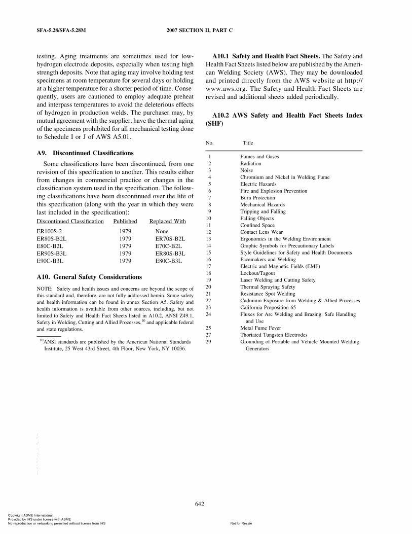
SFA-5.28/SFA-5.28M 2007 SECTION II, PART C
testing. Aging treatments are sometimes used for low-hydrogen electrode deposits, especially when testing highstrength deposits. Note that aging may involve holding testspecimens at room temperature for several days or holdingat a higher temperature for a shorter period of time. Conse-quently, users are cautioned to employ adequate preheatand interpass temperatures to avoid the deleterious effectsof hydrogen in production welds. The purchaser may, bymutual agreement with the supplier, have the thermal agingof the specimens prohibited for all mechanical testing doneto Schedule I or J of AWS A5.01.
A9. Discontinued Classifications
Some classifications have been discontinued, from onerevision of this specification to another. This results eitherfrom changes in commercial practice or changes in theclassification system used in the specification. The follow-ing classifications have been discontinued over the life ofthis specification (along with the year in which they werelast included in the specification):Discontinued Classification Published Replaced With
ER100S-2 1979 NoneER80S-B2L 1979 ER70S-B2LE80C-B2L 1979 E70C-B2LER90S-B3L 1979 ER80S-B3LE90C-B3L 1979 E80C-B3L
A10. General Safety Considerations
NOTE: Safety and health issues and concerns are beyond the scope ofthis standard and, therefore, are not fully addressed herein. Some safetyand health information can be found in annex Section A5. Safety andhealth information is available from other sources, including, but notlimited to Safety and Health Fact Sheets listed in A10.2, ANSI Z49.1,Safety in Welding, Cutting and Allied Processes,10 and applicable federaland state regulations.
10ANSI standards are published by the American National StandardsInstitute, 25 West 43rd Street, 4th Floor, New York, NY 10036.
642
A10.1 Safety and Health Fact Sheets. The Safety andHealth Fact Sheets listed below are published by the Ameri-can Welding Society (AWS). They may be downloadedand printed directly from the AWS website at http://www.aws.org. The Safety and Health Fact Sheets arerevised and additional sheets added periodically.
A10.2 AWS Safety and Health Fact Sheets Index(SHF)
No. Title
1 Fumes and Gases2 Radiation3 Noise4 Chromium and Nickel in Welding Fume5 Electric Hazards6 Fire and Explosion Prevention7 Burn Protection8 Mechanical Hazards9 Tripping and Falling
10 Falling Objects11 Confined Space12 Contact Lens Wear13 Ergonomics in the Welding Environment14 Graphic Symbols for Precautionary Labels15 Style Guidelines for Safety and Health Documents16 Pacemakers and Welding17 Electric and Magnetic Fields (EMF)18 Lockout/Tagout19 Laser Welding and Cutting Safety20 Thermal Spraying Safety21 Resistance Spot Welding22 Cadmium Exposure from Welding & Allied Processes23 California Proposition 6524 Fluxes for Arc Welding and Brazing: Safe Handling
and Use25 Metal Fume Fever27 Thoriated Tungsten Electrodes29 Grounding of Portable and Vehicle Mounted Welding
Generators
Copyright ASME International Provided by IHS under license with ASME
Not for ResaleNo reproduction or networking permitted without license from IHS
--`,,```,,,,````-`-`,,`,,`,`,,`---