setup - mail.rsgc.on.camail.rsgc.on.ca/~cdarcy/pdfs/cnc user guide.docx · web viewthe setup of...
TRANSCRIPT
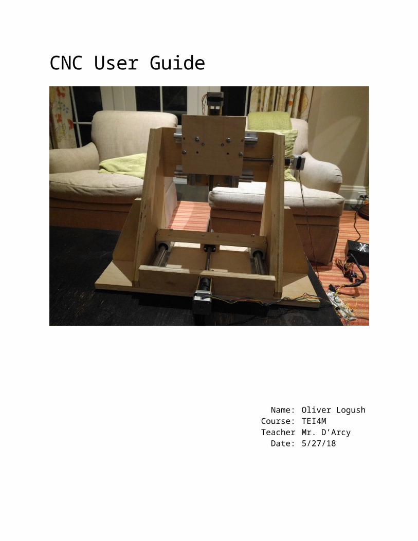
CNC User Guide
Name: Oliver LogushCourse: TEI4MTeacher Mr. D’Arcy
Date: 5/27/18

Oliver Logush CNC User Guide
Table of ContentsSetup.......................................................................................................................................1
Firmware Configuration...........................................................................................................1
Device Configuration Table......................................................................................................1
Debugging...............................................................................................................................4Error Codes......................................................................................................................................4Alarm Codes....................................................................................................................................6
Software..................................................................................................................................7Chilipeppr........................................................................................................................................7GRBL Library....................................................................................................................................8Serial Port JSON Server....................................................................................................................8
Connections............................................................................................................................9
Making GCODE Files..............................................................................................................10
Probing..................................................................................................................................11
Setting Up a Cut.....................................................................................................................12
ii
Oliver Logush CNC User Guide
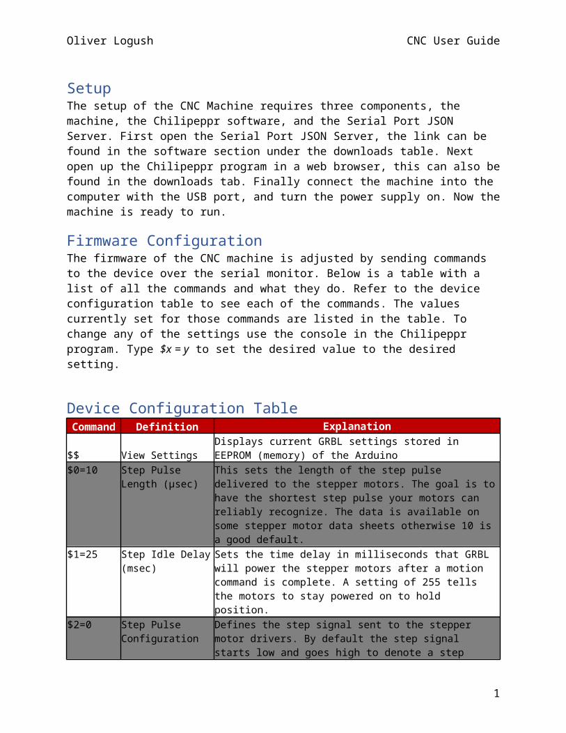
SetupThe setup of the CNC Machine requires three components, the machine, the Chilipeppr software, and the Serial Port JSON Server. First open the Serial Port JSON Server, the link can be found in the software section under the downloads table. Next open up the Chilipeppr program in a web browser, this can also be found in the downloads tab. Finally connect the machine into the computer with the USB port, and turn the power supply on. Now the machine is ready to run.
Firmware ConfigurationThe firmware of the CNC machine is adjusted by sending commands to the device over the serial monitor. Below is a table with a list of all the commands and what they do. Refer to the device configuration table to see each of the commands. The values currently set for those commands are listed in the table. To change any of the settings use the console in the Chilipeppr program. Type $x = y to set the desired value to the desired setting.
Device Configuration TableCommand Definition Explanation
$$ View SettingsDisplays current GRBL settings stored in EEPROM (memory) of the Arduino
$0=10 Step Pulse Length (µsec)
This sets the length of the step pulse delivered to the stepper motors. The goal is to have the shortest step pulse your motors can reliably recognize. The data is available on some stepper motor data sheets otherwise 10 is a good default.
$1=25 Step Idle Delay (msec) Sets the time delay in milliseconds that GRBL will power the stepper motors after a motion command is complete. A setting of 255 tells the motors to stay powered on to hold position.
$2=0 Step Pulse Configuration
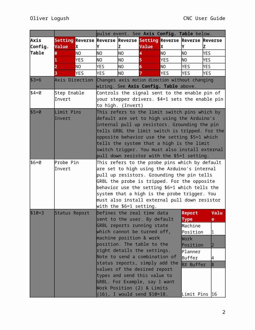
Defines the step signal sent to the stepper motor drivers. By default the step signal starts low and goes high to denote a step pulse event. See Axis Config. Table below.
AxisConfig.Table
Setting Value
Reverse X Reverse Y Reverse Z Setting Value
Reverse X Reverse Y Reverse Z
0 NO NO NO 4 NO NO YES1 YES NO NO 5 YES NO YES2 NO YES NO 6 NO YES YES3 YES YES NO 7 YES YES YES
$3=6 Axis Direction Changes axis motion direction without changing wiring. See Axis Config. Table above.
$4=0 Step Enable Invert Controls the signal sent to the enable pin of your stepper drivers. $4=1 sets the enable pin to high. (Invert)
$5=0 Limit Pins Invert This refers to the limit switch pins which by default are set to high using the Arduino's internal pull up resistors. Grounding the pin tells GRBL the limit switch is tripped. For the opposite behavior use the setting $5=1 which tells the system that a high is the limit switch trigger. You must also install external pull down resistor with the $5=1 setting.
1
Oliver Logush CNC User Guide
$6=0 Probe Pin Invert This refers to the probe pins which by default are set to high using the Arduino's internal pull up resistors. Grounding the pin tells GRBL the probe is tripped. For the opposite behavior use the setting $6=1 which tells the system that a high is the probe trigger. You must also install external pull down resistor with the $6=1 setting.
$10=3 Status Report Defines the real time data sent to the user. By default GRBL reports running state which cannot be turned off, machine position & work position. The table to the right details the settings. Note to send a combination of status reports, simply add the values of the desired report types and send this value to GRBL. For Example, say I want Work Position (2) & Limits (16), I would send $10=18.
Report Type ValueMachine Position 1Work Position 2Planner Buffer 4RX Buffer 8
Limit Pins 16$11=0.020 Junction Deviation
(mm)Think of this as cornering speed. A high values allows for fast motion around corners but increases the risk of missed steps resulting in decreased accuracy. Conversely, lower values reduce the speed around a corner decreasing the risk of missing steps while potentially improving accuracy.
$12=0.002 Arc Tolerance (mm) GRBL treats curves as a collection of small straight lines. This setting defines how smooth the curves will be. The default is .002mm and will not likely need to be changed as this value is below the accuracy of most machines.
$13=0 Feedback UnitsSets position feedback units from mm to inches. $13=1 for inches or $13=0 for mm
$20=0 Soft Limits (Enable/Disable)
Requires "Homing" be enabled and checks to see if gCode commands will exceed the travel limits of the machine. $20=1 Enable $20=0 Disable
$21=0 Hard Limits (Enable/Disable)
Requires limit switches be installed and looks for one of the limit switches to be activated which triggers "Alarm" mode. In this mode, all machine motion, the spindle and coolant are shutdown.
$22=0 Homing Cycle(Enable/Disable)
Requires limit switches be installed. Enabling this will lock out all gCode commands until a "Homing" cycle is run.
$23=1 Homing Cycle Direction
Allows the user to change the direction of the homing cycle us the values from the Axis Config. Table on page 1.
$24=50.000 Homing Feed (mm/min)
Feed rate used in the "Homing" cycle once the limit switches are located. The lower the value the more repeatable the zero position.
$25=635.000
Homing Seek (mm/min)
Feed rate used in the "Homing" cycle to locate the limit switches. Set this to the highest value that does not cause the machine to crash into the limit switches.
$26=250 Homing Debounce (msec)
Length of the software delay in milliseconds that minimizes switch noise. A valuebetween 5 an 25 is typical.
$27=1.000 Homing Pull-off (mm) Tells the machine how far to move away from the limit switches after finding the "Home" position so as not to trigger the hard limits.
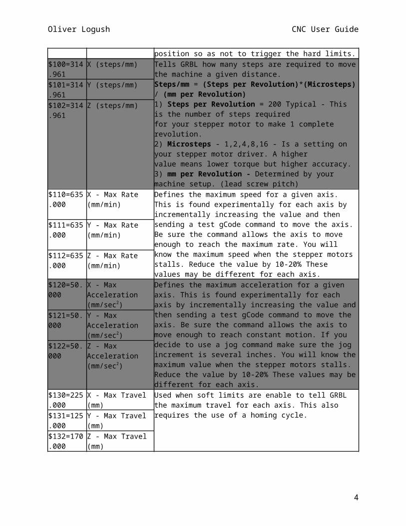
$100=314.961
X (steps/mm) Tells GRBL how many steps are required to move the machine a given distance.
2
Oliver Logush CNC User Guide
Steps/mm = (Steps per Revolution)*(Microsteps) / (mm per Revolution)1) Steps per Revolution = 200 Typical - This is the number of steps requiredfor your stepper motor to make 1 complete revolution.2) Microsteps - 1,2,4,8,16 - Is a setting on your stepper motor driver. A highervalue means lower torque but higher accuracy.3) mm per Revolution - Determined by your machine setup. (lead screw pitch)
$101=314.961
Y (steps/mm)
$102=314.961
Z (steps/mm)
$110=635.000
X - Max Rate (mm/min)
Defines the maximum speed for a given axis. This is found experimentally for each axis by incrementally increasing the value and then sending a test gCode command to move the axis. Be sure the command allows the axis to move enough to reach the maximum rate. You will know the maximum speed when the stepper motors stalls. Reduce the value by 10-20% These values may be different for each axis.
$111=635.000
Y - Max Rate (mm/min)
$112=635.000
Z - Max Rate (mm/min)
$120=50.000
X - Max Acceleration(mm/sec2)
Defines the maximum acceleration for a given axis. This is found experimentally for each axis by incrementally increasing the value and then sending a test gCode command to move the axis. Be sure the command allows the axis to move enough to reach constant motion. If you decide to use a jog command make sure the jog increment is several inches. You will know the maximum value when the stepper motors stalls. Reduce the value by 10-20% These values may be different for each axis.
$121=50.000
Y - Max Acceleration(mm/sec2)
$122=50.000
Z - Max Acceleration(mm/sec2)
$130=225.000
X - Max Travel (mm) Used when soft limits are enable to tell GRBL the maximum travel for each axis. This also requires the use of a homing cycle.
$131=125.000
Y - Max Travel (mm)
$132=170.000
Z - Max Travel (mm)
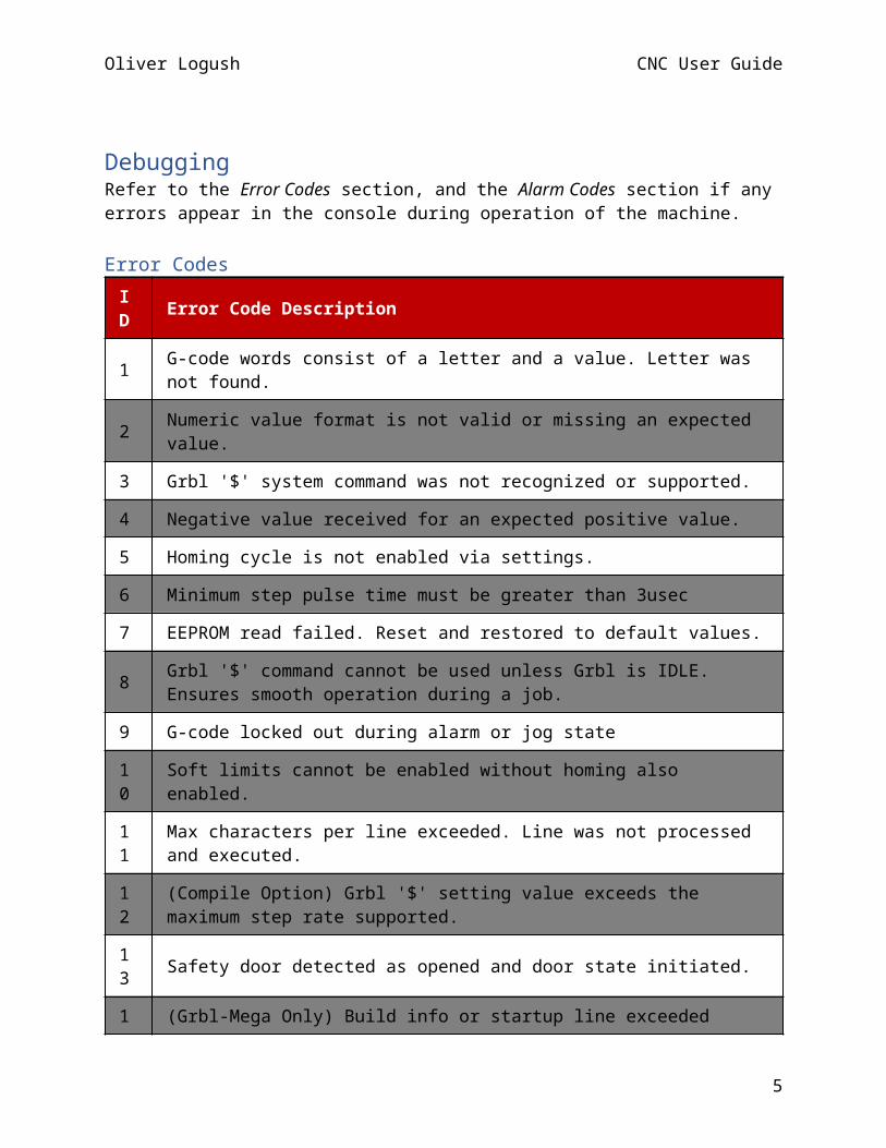
DebuggingRefer to the Error Codes section, and the Alarm Codes section if any errors appear in the console during operation of the machine.
Error CodesID Error Code Description
1 G-code words consist of a letter and a value. Letter was not found.
2 Numeric value format is not valid or missing an expected value.
3 Grbl '$' system command was not recognized or supported.
3

Oliver Logush CNC User Guide
ID Error Code Description
4 Negative value received for an expected positive value.
5 Homing cycle is not enabled via settings.
6 Minimum step pulse time must be greater than 3usec
7 EEPROM read failed. Reset and restored to default values.
8 Grbl '$' command cannot be used unless Grbl is IDLE. Ensures smooth operation during a job.
9 G-code locked out during alarm or jog state
10 Soft limits cannot be enabled without homing also enabled.
11 Max characters per line exceeded. Line was not processed and executed.
12 (Compile Option) Grbl '$' setting value exceeds the maximum step rate supported.
13 Safety door detected as opened and door state initiated.
14 (Grbl-Mega Only) Build info or startup line exceeded EEPROM line length limit.
15 Jog target exceeds machine travel. Command ignored.
16 Jog command with no '=' or contains prohibited g-code.
17 Laser mode requires PWM output.
20 Unsupported or invalid g-code command found in block.
21 More than one g-code command from same modal group found in block.
22 Feed rate has not yet been set or is undefined.
23 G-code command in block requires an integer value.
24 Two G-code commands that both require the use of the XYZ axis words were detected in the block.
25 A G-code word was repeated in the block.
26 A G-code command implicitly or explicitly requires XYZ axis words in the block, but none were detected.
27 N line number value is not within the valid range of 1 - 9,999,999.
28 A G-code command was sent, but is missing some required P or L value words in the line.
29 Grbl supports six work coordinate systems G54-G59. G59.1, G59.2, and G59.3are not
4
Oliver Logush CNC User Guide
ID Error Code Description
supported.
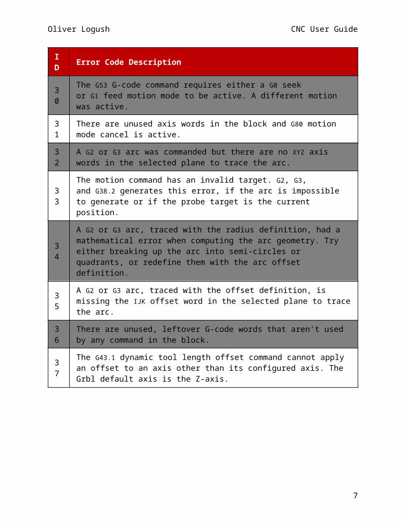
30 The G53 G-code command requires either a G0 seek or G1 feed motion mode to be active. A different motion was active.
31 There are unused axis words in the block and G80 motion mode cancel is active.
32 A G2 or G3 arc was commanded but there are no XYZ axis words in the selected plane to trace the arc.
33 The motion command has an invalid target. G2, G3, and G38.2 generates this error, if the arc is impossible to generate or if the probe target is the current position.
34 A G2 or G3 arc, traced with the radius definition, had a mathematical error when computing the arc geometry. Try either breaking up the arc into semi-circles or quadrants, or redefine them with the arc offset definition.
35 A G2 or G3 arc, traced with the offset definition, is missing the IJK offset word in the selected plane to trace the arc.
36 There are unused, leftover G-code words that aren't used by any command in the block.
37 The G43.1 dynamic tool length offset command cannot apply an offset to an axis other than its configured axis. The Grbl default axis is the Z-axis.
5
Oliver Logush CNC User Guide
Alarm Codes
ID Alarm Code Description
1 Hard limit triggered. Machine position is likely lost due to sudden and immediate halt. Re-homing is highly recommended.
2 G-code motion target exceeds machine travel. Machine position safely retained. Alarm may be unlocked.
3 Reset while in motion. Grbl cannot guarantee position. Lost steps are likely. Re-homing is highly recommended.
4 Probe fail. The probe is not in the expected initial state before starting probe cycle, where G38.2 and G38.3 is not triggered and G38.4 and G38.5 is triggered.
5 Probe fail. Probe did not contact the workpiece within the programmed travel for G38.2 and G38.4.
6 Homing fail. Reset during active homing cycle.
7 Homing fail. Safety door was opened during active homing cycle.
8 Homing fail. Cycle failed to clear limit switch when pulling off. Try increasing pull-off setting or check wiring.
9 Homing fail. Could not find limit switch within search distance. Defined as 1.5 * max_travel on search and 5 * pulloff on locate phases.
6

Oliver Logush CNC User Guide
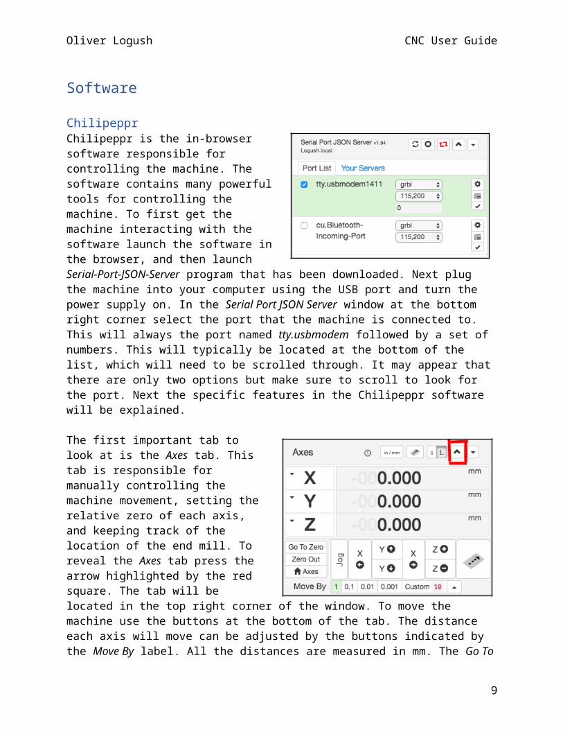
SoftwareChilipepprChilipeppr is the in-browser software responsible for controlling the machine. The software contains many powerful tools for controlling the machine. To first get the machine interacting with the software launch the software in the browser, and then launch Serial-Port-JSON-Server program that has been downloaded. Next plug the machine into your computer using the USB port and turn the power supply on. In the Serial Port JSON Server window at the bottom right corner select the port that the machine is connected to. This will always the port named tty.usbmodem followed by a set of numbers. This will typically be located at the bottom of the list, which will need to be scrolled through. It may appear that there are only two options but make sure to scroll to look for the port. Next the specific features in the Chilipeppr software will be explained.
The first important tab to look at is the Axes tab. This tab is responsible for manually controlling the machine movement, setting the relative zero of each axis, and keeping track of the location of the end mill. To reveal the Axes tab press the arrow highlighted by the red square. The tab will be located in the top right corner of the window. To move the machine use the buttons at the bottom of the tab. The distance each axis will move can be adjusted by the buttons indicated by the Move By label. All the distances are measured in mm. The Go To Zero button will cause each axis to move to its zero position. The Zero Out button will set each axis’ current location as the new zero position. The remaining buttons are not needed for the operation of this machine and should be ignored.
The Console tab located in the bottom left of the window is responsible for sending commands to the machine. This will be used primarily to change the settings of the machine. Changing the settings can be found in the Configuration section of the manual.
7
Oliver Logush CNC User Guide
The Gcode tab can be found in the middle left of the window. This is what is used to send the Gcode to the machine. The play button will begin the cut on the machine. Be warned that the pause button on this tab will not stop a cut. This is because the software buffers many of the instructions to the machine, and it will stop sending, but many instructions have already been sent so the machine will continue operation. If the user desires to immediately stop an operation unplug the machine from the computer. This will stop the cut, but everything will need to be setup again.
The final tab to examine is the GRBL Workspace tab located at the top left of the window. This is used to enable certain widgets, which are additional tabs with functionality to enhance the software. A menu of these can be shown by clicking the Widgets drop down menu. The only two widgets that will be used for this machine is the Auto Level and Eagle BRD Import widget. The Auto Level widget is used for the probing which is discussed in the Probing section. To enable this widget simply click the labelled button in the dropdown menu, and the tab should appear on the left had side of the window. To make it go away simply click that same button again. The Eagle BRD Import widget will automatically appear when an Eagle board file is dragged into the window. The use of this widget is discussed in the Making a Gcode File section.
GRBL LibraryThe GRBL Library contains the code that is loaded onto the Arduino. To get this on the Arduino download the library from the link in the downloads table. Add the library to the Arduino IDE, and then open File>Examples>GRBL>GRBLUpload. Upload this program to the Arduino and it is ready.
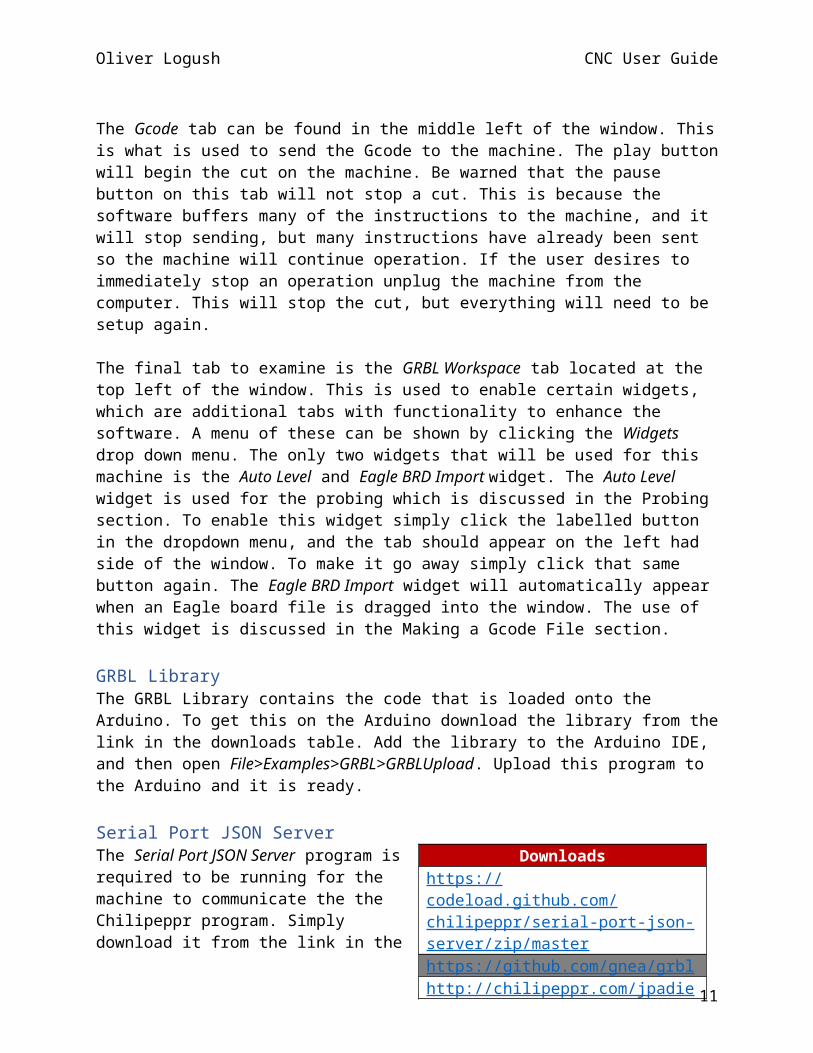
Serial Port JSON ServerThe Serial Port JSON Server program is required to be running for the machine to communicate the the Chilipeppr program. Simply download it from the link in the download table. Unzip the folder and run the Unix Executable file contained in the folder. Each time the machine is being used this program must be running.
ConnectionsThe connections for the machine are all already made. However, if an issue arises where connections become unplugged, follow the image provided for reconnecting wires. When determining which of the motor controllers control which axis, inspect the motor controllers, and a label on each controller will be found
Downloadshttps://codeload.github.com/chilipeppr/serial-port-json-server/zip/masterhttps://github.com/gnea/grblhttp://chilipeppr.com/jpadie
8

Oliver Logush CNC User Guide
indicating which axis each of them are on. Additionally, the pin labelling for the controllers are under the PCB. Instead of removing the PCB to determine which wire is which, there is a label on each wire indicating the pin it is connected to. The two pins that will need to be swapped around are the probing pins. An alligator clip is attached to the probe pin so that the user can clip it onto the mill bit when probing the board. The other pin is one that is connected to the GND pin on the Arduino. This is meant to be soldered onto the board when probing. Simply solder it onto the corner of the board that is being probed. The pins that do not need to be connected is A0 – A4. Pin 0, 1, 11, 13. The limit switches that are connected are meant to prevent the machine from running off of the lead screws. If one of the limit switches is triggered, the operation of the machine will stop completely.
9
Oliver Logush CNC User Guide
Making GCODE FilesThe Chilipeppr software has a built-in tool for turning Eagle board files into GCODE files. When designing a board to be cut on the machine ensure that the board is one sided. To do this first drag your board file into the Chilipeppr window. The first window that appears is the Render>Board window. Select the layer on the board that you want to cut, in this case it is the top layer. Ignore the rest of the options on this tab. Next go to the signals tab and type in .5 mm in the Inflate Milling Path text field. Next go to the Gcode>Traces tab. The Depth of Milling Traces setting will depend on the copper being used. Use the guide in the window to determine your trace depth. Currently, the copper being used is 1oz. Also in that window is the Avoid Tracing Board Dimensions, checkbox. Make sure this is unchecked, as it mistakes traces for board dimensions and avoids cutting these traces. Next move to the Drilling tab. Uncheck all of the boxes in this tab because the machine is only intended for cutting traces, not drilling the holes. Next move to the Milling tab, and uncheck all of the boxes there. The V-Bit on the mill is not meant to cut through the entire board. After this move to the Tabs tab. Uncheck the Tabs (Board Holders) checkbox. These tabs are an alternate way of securing the board to the build plate that are not used by this machine. After this all of the settings have been made and the Gcode can be generated. First press the Refresh 3D Viewer button in the top right corner of the Eagle BRD window. This will show the path the mill will take in the preview window. The blue lines are the path of the mill. Ensure that the path follows your desired cut for the board. After this is confirmed press the Send Gcode to Workspace button. To confirm that the Gcode has been sent look in the Gcode tab. Press the arrow second to the right in the window, it is marked with the number 1 in the included image, to display the contents of the window. The first line of the Gcode should look like what is in the image. There will be a date and time stamp which shows when it was generated. Ensure that this matches when you created it. After this the Gcode can be sent to the machine by pressing the play button at the top of the toolbar.
10

Oliver Logush CNC User Guide
ProbingProbing is one of the most powerful features in the Chilipeppr software. It is used to account for any change in depth on the copper board if it is not perfectly level. To first set up a probe connect the alligator clip onto the bit on the end of the dremel. Next, solder the GND wire onto the copper board that will be probed. After this tape the board down to the center of the build plate. Set up the axes as described in the Setting Up a Cut section. Next open up the Auto Level widget under the Widgets drop down menu in the top left corner of the window. In the Pre-Run tab the Steps Every field will determine the distance between each probe location. The lower the value the more probe points on the board, and the resolution is better. The drawback of this is that it will take longer to probe. An ideal setting is 4mm. The next settings are the X and Y axes bounds for the region to be probed, these are labelled as the Start At, and End At, fields. Adjust these to fit the board that will be probed. A preview of the region that will be probed will show up in the program. This is useful to determine the Start At and End At values. The remaining values that are available to be adjusted are meant to set the Z axis movement. The Clearance Height setting does not need to be adjusted. This is the height above the board that the dremel will travel between probes at. The default setting of 1.5mm is ideal. The next setting is the Start Probing At field. This should be set to 1mm. This determines at which height the machine will begin registering a probe. The Probe Feedrate field is the speed at which the machine lowers the dremel to probe. This should be set to 1. The final setting that needs to be altered is the Max Negative Z. This should be set to -1.5. This is how far below zero the machine will go before it stops probing and sets off an alarm. After these settings have been altered go to the Run tab. Press the play button to start probing. Once the probing is finished, go to the Post Run tab. If the probing is successful, press the Send Auto-Levelled Gcode To Workspace button. This will alter the Z axis movement of the Gcode to account for any imperfections in the height of the copper. If something went wrong with the probing and another probe is required click the arrow at the top right of the tab, and click the Clear Probe Data button.
11
Oliver Logush CNC User Guide
Setting Up a CutTo set up a cut on the machine first refer to the Software section to ensure that the machine is properly connected to the computer. Next place a copper board in the center of the build plate on the machine. Using duct tape secure the board onto the plate. Cover all four sides of the board and crease the duct tape onto the build plate. Make sure that the board does not shift when pushed from the sides. Next move the machine manually using the Axes tab to reach where the machine zero for the cut should be. Make sure that the board has enough space for the cut in the X and Y directions. If probing is being used move the Z-axis to be as close to the board as possible without touching it, after the axes have been set press the Zero Out button. Next refer to the probing section to set that up. If probing is not being used move the end mill to being just barely above the axis. Next turn on the dremel, and lower the dremel until it is barely cutting into the board. Then, press the Zero Out button. After this press the play button in the Gcode tab to begin the cut. Once the cut is finished move the end mill far enough away from the board so that your hand will not be cut by the bit. After this carefully remove the tape surrounding the board and take the board off of the build plate.
12