set-up-software work bench v5 - · pdf fileshort form operations manual set-up-software work...
TRANSCRIPT

Short Form Operations Manual
Set-up-Software Work Bench v5 for SC-610-Series Servo Controllers
No. 900113 01/2003
08.01.2003-FA
®
HARMONIC DRIVE AG has tried to ensure that the information given in this manual is correct at time of going to print. However Harmonic Drive AG may not be held responsible for any typographical mistakes or errors in contents of this manual. The information is subject to change without prior notice. Harmonic Drive AG would appreciate notice of any mistakes in the text. HARMONIC DRIVE AG owns the copyright to this document, which is supplied to customers on the understanding that it will not be reproduced or disclosed in whole or in part, without the express permission of Harmonic Drive AG. Harmonic Drive AG Hoenbergstraße 14 D-65555 Limburg/ Lahn Germany Tel.: +49-6431/ 5008-0 Fax.: +49-6431/ 5008-18 Email: [email protected] Internet: www.harmonicdrive.de
www.supportme.net/harmonicdrive
�2003

Operations Manual Work Bench v5 Page 1
Harmonic Drive AG 900113 01/2003
Contents Page 1 About this Manual 2 2 Introduction of Work Bench 2 3 System Requirements 3 4 Installation Guidelines 3 5 Software Structure 4 5.1 Main Menus 4 5.2 Tool Boxes (Set-up and Application) 5 5.3 Monitoring 6 5.4 Help-Functions 8 5.4.1 Online-Help 8 5.4.2 Support-Me 9 5.4.3 Online-Help for Fine Tuning 9 6 Drive Set-up I (Basic Steps on ex. Velocity Control Mode) 10 7 Drive Set-up II (Position-Table and PLC) 19 7.1 PLC-Set-up for Velocity Control 19 7.2 PLC-Set-up for Position Control 20 7.3 Programming the Pre-set Position Table 21 8 Tuning Guidelines 24 9 Data Backup 26 9.1 Generating a Parameter File 26 9.2 Downloading a Parameter File into the Drive 28 10 Downloading a new Firmware Version 30 11 Programming with ActiveX-Controls 33 11.1 General Description 33 11.2 Example for VBA 34

Page 2 Operations Manual Work Bench v5
Harmonic Drive AG 900113 01/2003
1 About this Manual This manual gives a brief overview of the major functions of the front-end tool named Work Bench v5! The given information should enable the user to set-up and run typical applications like Velocity Control and Position Control Mode. Further more basic tuning guidelines and Help-functions are given as well as recommendations for data backup. More detailed information and advices can be found in the help-file (press F1) of the Work Bench in parallel to this short form manual! If the application requires further specific support please contact your local distributor or Harmonic Drive directly! It is recommended to inquire for support during commissioning the drive system in case you are not familiar with this drive system or if your expertise in terms of the software handling might be limited. Harmonic Drive is prepared to offer this support on special request. Legend:
This is an INFORMATION sign. By observing this information whilst installing the drive future-operating problems may be avoided.
This sign means ATTENTION. Information in an ATTENTION box must always be observed otherwise dangerous situations for equipment and personnel may result.
2 Introduction of Work Bench The front-end tool Work Bench v5 is a software package designed for setting up SC-610-series servo controllers. These servo controllers are prepared to drive the Harmonic Drive AC-servo actuators (ex. FHA-C-series). The software as well as the documentation is supplied on CD-ROM or via the Internet. www.harmonicdrive.de -> for product information www.supportme.net/harmonicdrive -> for downloading the Work Bench and Firmware Major functions are:
- Drive set-up with the help of the commissioning wizard - Auto-tune and fine-tune functions - PLC-programming - Programming of 16 or up to 256 pre-set positions - JOG-Mode - Data-Recording - Parameter-Backup - Extensive Help functions incl. Supportme.txt for Email - ActiveX library available for interfacing to PC-programming environment
Operations Manual Work Bench v5 Page 3
Harmonic Drive AG 900113 01/2003
3 System Requirements Hardware requirements (minimum): Processor: Intel Pentium / 133 MHz RAM: 32MByte Hard Disk Space: 40Mbyte Screen: 800 x 600 (min.) Recommended: Intel Pentium III, 64 MB RAM, 200 MHz, and 60MB hard disk
space free Software requirements: Recommended: Windows 98, Windows ME, Windows NT (Service Pack 6), Windows 2000 or Windows XP 4 Installation Guidelines Please contact your administrator prior to installation in order to check your privileges for executing a new software installation. To install the Work Bench software on your computer's hard disk, please follow the sequence described below: 1.) Start Windows. Make sure, that no other programs are running, while Installation
of Work Bench is done.
2.) Place Installation CD ROM in your computer's CD ROM drive.
3.) Look for your CD ROM drive and double click on Setup_xxxx.exe. (xxxx: Build version)
4.) Please proceed according to the demands from the installation process, given by the install shield.
5.) Reboot your computer after successful installation After installation process is finished, a Work Bench Icon is created on your desktop. Double clicking this icon will start the Work Bench set-up program.
The Internet Explorer 4SP2 or higher must be installed!Explorer 5.5 and Service Pack 6 are recommended toavoid problems with NT4.0!

Page 4 Operations Manual Work Bench v5
Harmonic Drive AG 900113 01/2003
5 Software Structure 5.1 Main Menus
Monitoring
Operating Mode
Actuator Type
Controller Type
Tools-Menu with Control Mode selection and handling of the Parameter Table
Toolboxes forSetup andApplication
Operations Manual Work Bench v5 Page 5
Harmonic Drive AG 900113 01/2003
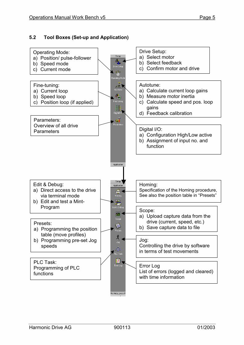
5.2 Tool Boxes (Set-up and Application)
Drive Setup: a) Select motor b) Select feedback c) Confirm motor and drive
Operating Mode: a) Position/ pulse-follower b) Speed mode c) Current mode
Autotune: a) Calculate current loop gains b) Measure motor inertia c) Calculate speed and pos. loop
gains d) Feedback calibration
Fine-tuning: a) Current loop b) Speed loop c) Position loop (if applied)
Digital I/O: a) Configuration High/Low active b) Assignment of input no. and
function
Parameters: Overview of all drive Parameters
Homing: Specification of the Homing procedure,See also the position table in “Presets”
Edit & Debug: a) Direct access to the drive
via terminal mode b) Edit and test a Mint-
Program Scope: a) Upload capture data from the
drive (current, speed, etc.) b) Save capture data to file
Presets: a) Programming the position
table (move profiles) b) Programming pre-set Jog
speeds Jog: Controlling the drive by software in terms of test movements
PLC Task: Programming of PLC functions
Error Log List of errors (logged and cleared) with time information
Page 6 Operations Manual Work Bench v5
Harmonic Drive AG 900113 01/2003
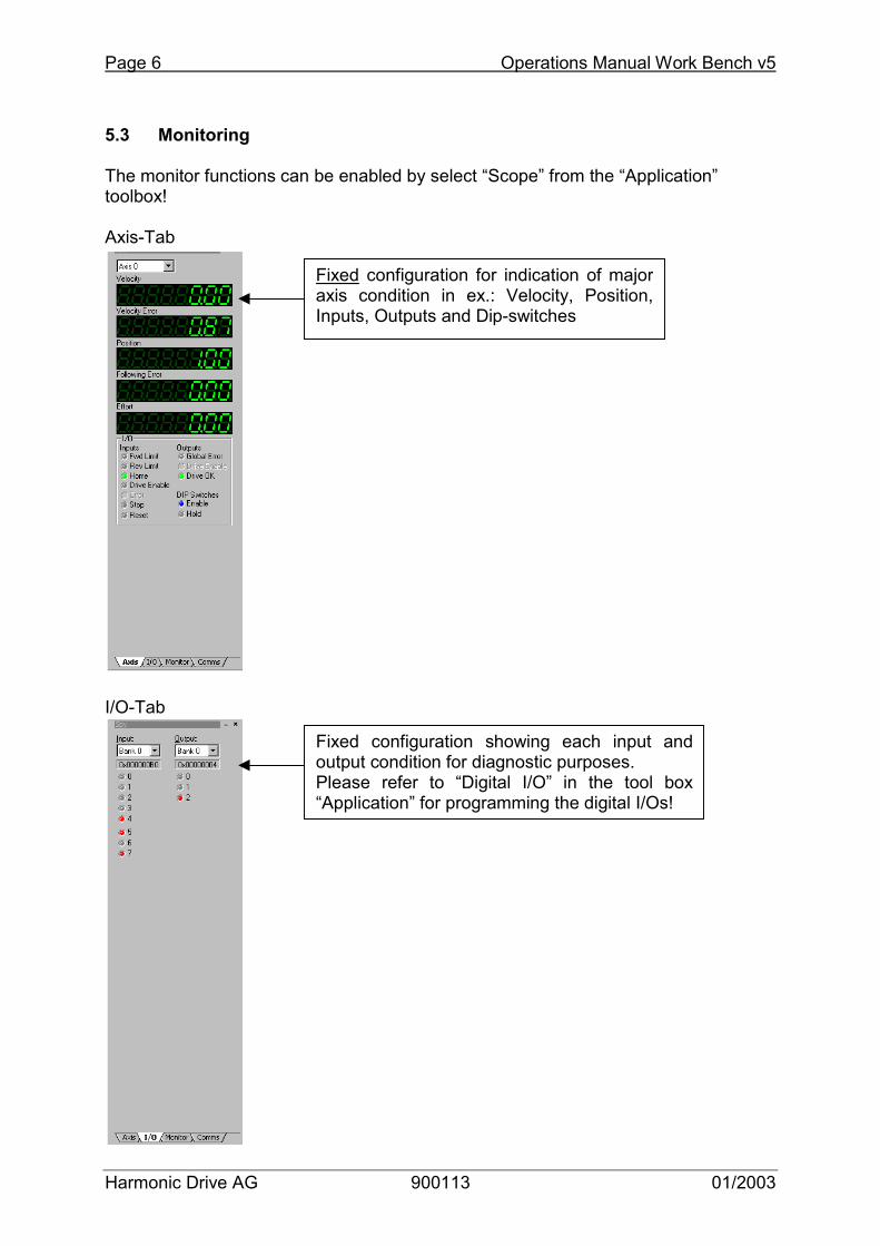
5.3 Monitoring The monitor functions can be enabled by select “Scope” from the “Application” toolbox! Axis-Tab I/O-Tab
Fixed configuration for indication of majoraxis condition in ex.: Velocity, Position,Inputs, Outputs and Dip-switches
Fixed configuration showing each input andoutput condition for diagnostic purposes. Please refer to “Digital I/O” in the tool box“Application” for programming the digital I/Os!
Operations Manual Work Bench v5 Page 7
Harmonic Drive AG 900113 01/2003
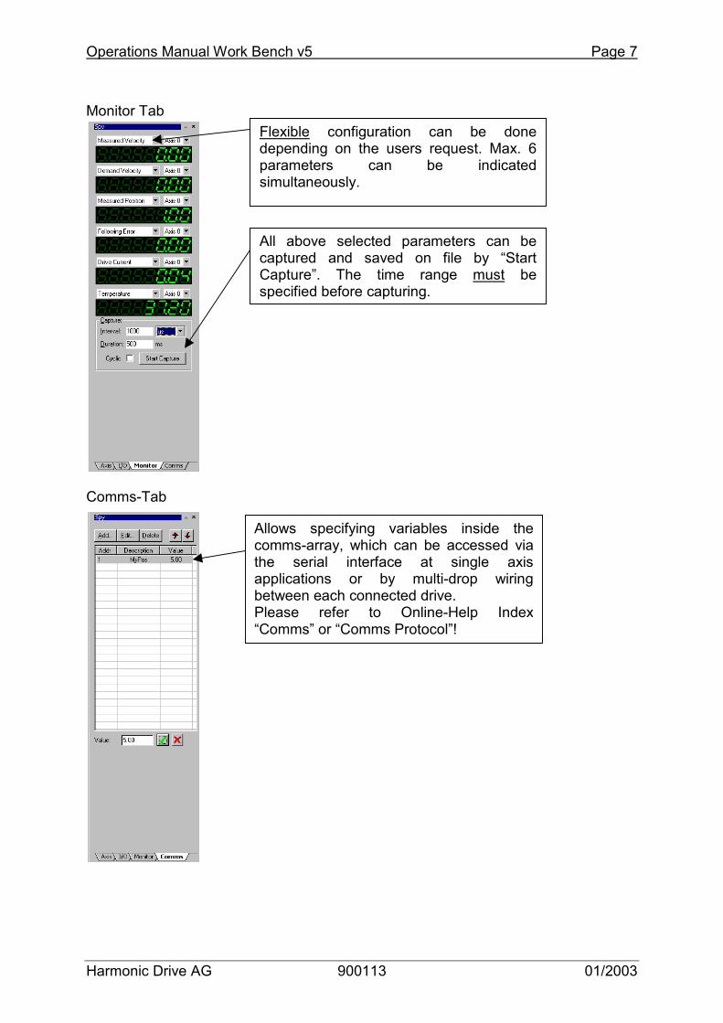
Monitor Tab Comms-Tab
Flexible configuration can be done depending on the users request. Max. 6parameters can be indicatedsimultaneously.
All above selected parameters can be captured and saved on file by “StartCapture”. The time range must be specified before capturing.
Allows specifying variables inside the comms-array, which can be accessed via the serial interface at single axisapplications or by multi-drop wiring between each connected drive. Please refer to Online-Help Index “Comms” or “Comms Protocol”!
Page 8 Operations Manual Work Bench v5
Harmonic Drive AG 900113 01/2003
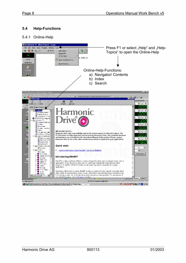
5.4 Help-Functions 5.4.1 Online-Help
Press F1 or select „Help“ and „Help-Topics“ to open the Online-Help
Online-Help-Functions: a) Navigator/ Contents b) Index c) Search
Operations Manual Work Bench v5 Page 9
Harmonic Drive AG 900113 01/2003
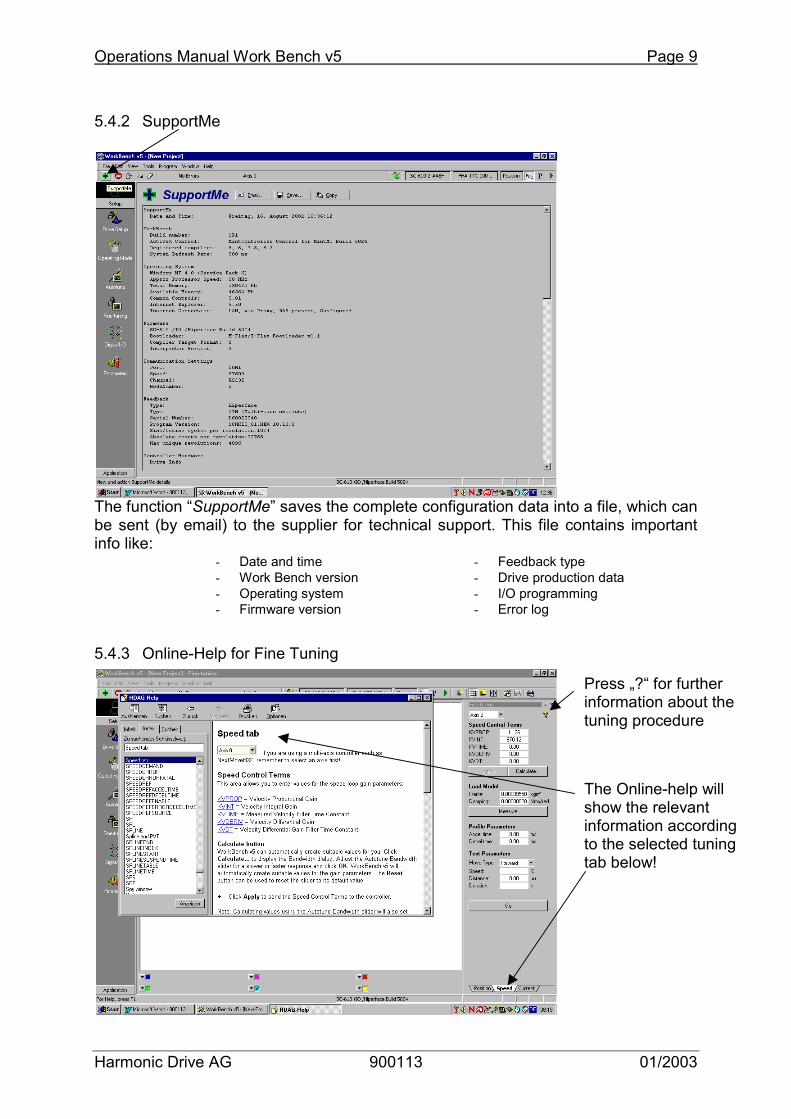
5.4.2 SupportMe The function “SupportMe” saves the complete configuration data into a file, which can be sent (by email) to the supplier for technical support. This file contains important info like: 5.4.3 Online-Help for Fine Tuning
- Feedback type - Drive production data - I/O programming - Error log
- Date and time - Work Bench version - Operating system - Firmware version
Press „?“ for further information about the tuning procedure
The Online-help will show the relevant information according to the selected tuning tab below!

Page 10 Operations Manual Work Bench v5
Harmonic Drive AG 900113 01/2003
6 Drive Set-up I (Example Procedure for Velocity Control Mode) Important Notice:
- This procedure is typically not required since the basic drive set-up is prepared ex factory Harmonic Drive
- This set-up procedure is only recommended in case major changes concerning motor type or operating mode are required or the drive has been set to the initial “factory defaults”!
a) Start Software by double click on icon „Work Bench v5“ at the desktop b) Start Menu Work Bench c) Select Controller Attention: In case communication can not established please check:
�� Is the correct cable applied and properly wired? �� Is the PC-interface working correctly? �� Is the drive powered up? (230V or 24V at units with connector
terminal for X1.9 u. 10)
Click on „Start New Project“
Click on „Scan“ and establish communication with the drive
„Only scan COM1“ in case COM1 on the PC is in use
Wait until SC-610 is indicated
Activate „Launch Commissioning Wizard“ and click on „Select“
Operations Manual Work Bench v5 Page 11
Harmonic Drive AG 900113 01/2003
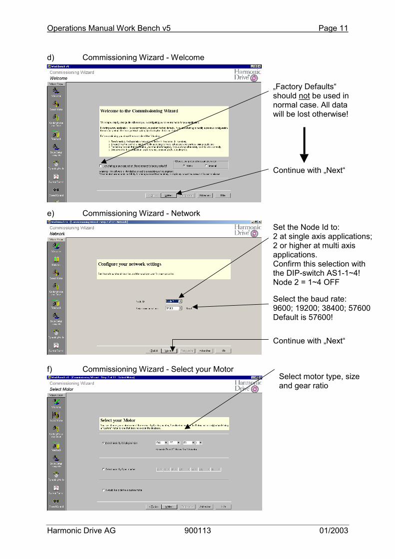
d) Commissioning Wizard - Welcome e) Commissioning Wizard - Network f) Commissioning Wizard - Select your Motor
„Factory Defaults“ should not be used in normal case. All data will be lost otherwise!
Continue with „Next“
Select motor type, size and gear ratio
Continue with „Next“
Set the Node Id to: 2 at single axis applications; 2 or higher at multi axis applications. Confirm this selection with the DIP-switch AS1-1~4! Node 2 = 1~4 OFF
Select the baud rate: 9600; 19200; 38400; 57600 Default is 57600!
Page 12 Operations Manual Work Bench v5
Harmonic Drive AG 900113 01/2003
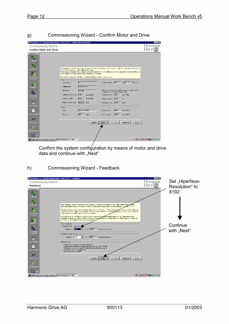
g) Commissioning Wizard - Confirm Motor and Drive h) Commissioning Wizard - Feedback
Confirm the system configuration by means of motor and drive data and continue with „Next“
Set „Hiperface-Resolution“ to 8192
Continue with „Next“
Operations Manual Work Bench v5 Page 13
Harmonic Drive AG 900113 01/2003
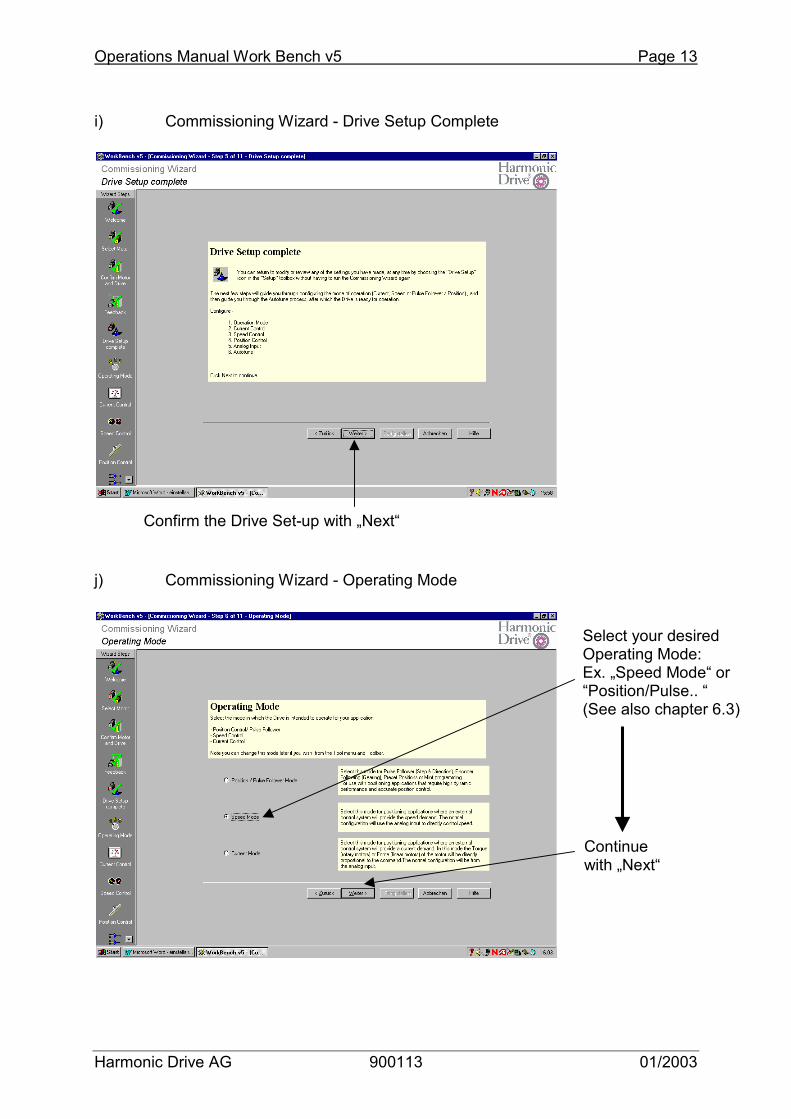
i) Commissioning Wizard - Drive Setup Complete j) Commissioning Wizard - Operating Mode
Confirm the Drive Set-up with „Next“
Select your desired Operating Mode: Ex. „Speed Mode“ or “Position/Pulse.. “ (See also chapter 6.3)
Continue with „Next“
Page 14 Operations Manual Work Bench v5
Harmonic Drive AG 900113 01/2003
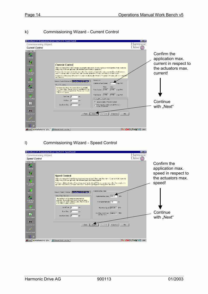
k) Commissioning Wizard - Current Control l) Commissioning Wizard - Speed Control
Confirm the application max. current in respect to the actuators max. current!
Continue with „Next“
Continue with „Next“
Confirm the application max. speed in respect to the actuators max. speed!
Operations Manual Work Bench v5 Page 15
Harmonic Drive AG 900113 01/2003
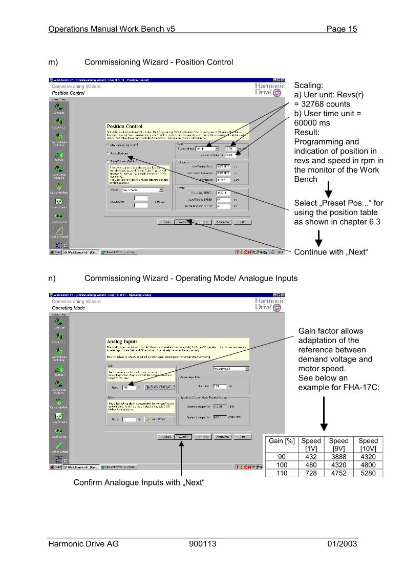
m) Commissioning Wizard - Position Control n) Commissioning Wizard - Operating Mode/ Analogue Inputs
Scaling: a) Uer unit: Revs(r) = 32768 counts b) User time unit = 60000 ms Result: Programming and indication of position in revs and speed in rpm in the monitor of the Work Bench
Continue with „Next“
Confirm Analogue Inputs with „Next“
Gain factor allows adaptation of the reference between demand voltage and motor speed. See below an example for FHA-17C:
Gain [%] Speed [1V]
Speed [9V]
Speed [10V]
90 432 3888 4320 100 480 4320 4800 110 728 4752 5280
Select „Preset Pos...“ for using the position table as shown in chapter 6.3
Page 16 Operations Manual Work Bench v5
Harmonic Drive AG 900113 01/2003
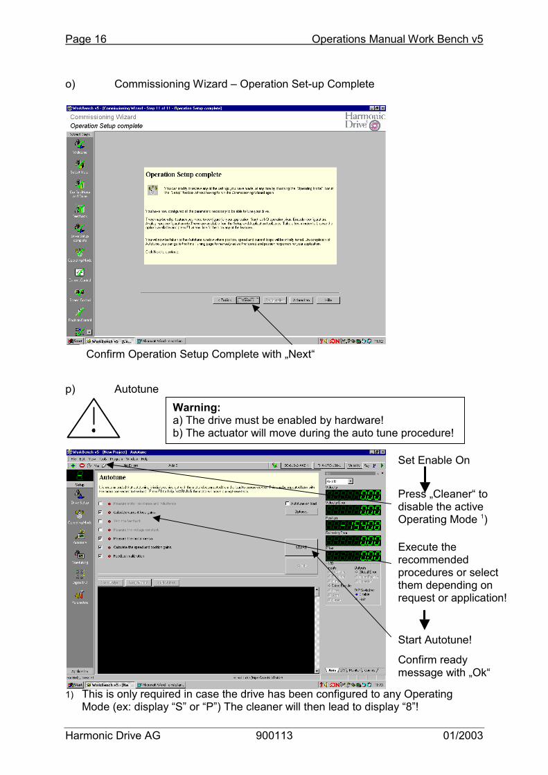
o) Commissioning Wizard – Operation Set-up Complete p) Autotune 1) This is only required in case the drive has been configured to any Operating
Mode (ex: display “S” or “P”) The cleaner will then lead to display “8”!
Confirm Operation Setup Complete with „Next“
Set Enable On
Start Autotune!
Confirm ready message with „Ok“
Warning: a) The drive must be enabled by hardware! b) The actuator will move during the auto tune procedure!
Execute the recommended procedures or select them depending on request or application!
Press „Cleaner“ to disable the active Operating Mode 1)
Operations Manual Work Bench v5 Page 17
Harmonic Drive AG 900113 01/2003
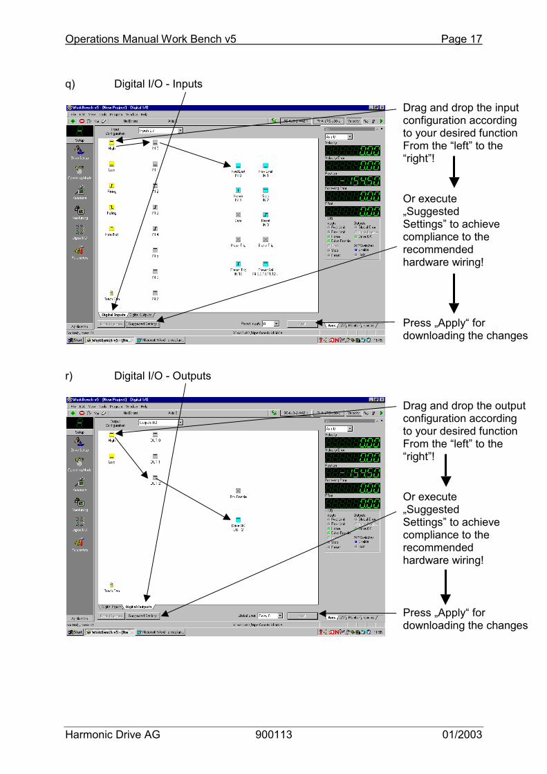
q) Digital I/O - Inputs r) Digital I/O - Outputs
Or execute „Suggested Settings” to achieve compliance to the recommended hardware wiring!
Drag and drop the input configuration according to your desired function From the “left” to the “right”!
Press „Apply“ for downloading the changes
Drag and drop the output configuration according to your desired function From the “left” to the “right”!
Or execute „Suggested Settings” to achieve compliance to the recommended hardware wiring!
Press „Apply“ for downloading the changes
Page 18 Operations Manual Work Bench v5
Harmonic Drive AG 900113 01/2003
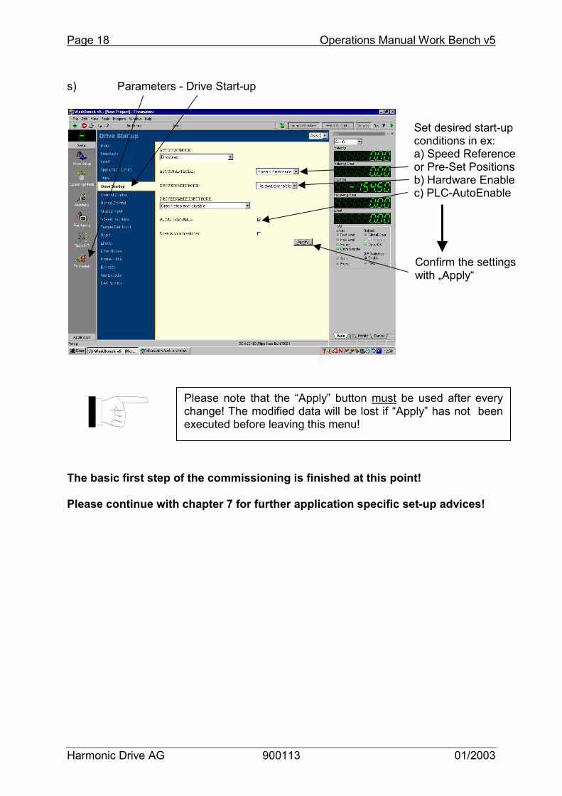
s) Parameters - Drive Start-up The basic first step of the commissioning is finished at this point! Please continue with chapter 7 for further application specific set-up advices!
Set desired start-up conditions in ex: a) Speed Reference or Pre-Set Positions b) Hardware Enable c) PLC-AutoEnable
Confirm the settings with „Apply“
Please note that the “Apply” button must be used after every change! The modified data will be lost if “Apply” has not beenexecuted before leaving this menu!
Operations Manual Work Bench v5 Page 19
Harmonic Drive AG 900113 01/2003
7 Drive Set-up II (PLC and Position-Table) The following procedures are required to be done by the user in order to adapt the drive to the desired application for example:
- Configuration of the PLC-function in case certain drive condition should be watched by the above control system or
- The drive is used as a position controller and position table must be programmed.
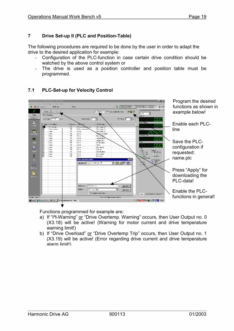
7.1 PLC-Set-up for Velocity Control
Functions programmed for example are: a) If “I²t-Warning” or “Drive Overtemp. Warning” occurs, then User Output no. 0
(X3.18) will be active! (Warning for motor current and drive temperaturewarning limit!)
b) If “Drive Overload” or “Drive Overtemp Trip” occurs, then User Output no. 1(X3.19) will be active! (Error regarding drive current and drive temperature alarm limit!)
Program the desired functions as shown in example below!
Enable the PLC-functions in general!
Enable each PLC-line
Save the PLC-configuration if requested: name.plc
Press “Apply” for downloading the PLC-data!
Page 20 Operations Manual Work Bench v5
Harmonic Drive AG 900113 01/2003
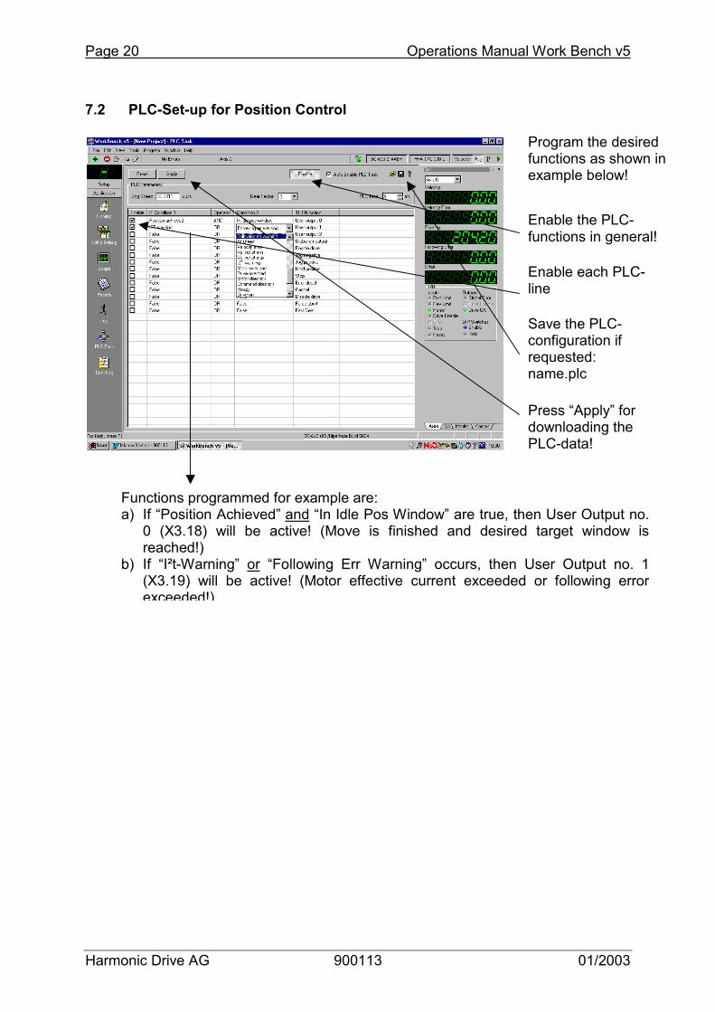
7.2 PLC-Set-up for Position Control
Functions programmed for example are: a) If “Position Achieved” and “In Idle Pos Window” are true, then User Output no.
0 (X3.18) will be active! (Move is finished and desired target window isreached!)
b) If “I²t-Warning” or “Following Err Warning” occurs, then User Output no. 1(X3.19) will be active! (Motor effective current exceeded or following errorexceeded!)
Program the desired functions as shown in example below!
Enable the PLC-functions in general!
Enable each PLC-line
Save the PLC-configuration if requested: name.plc
Press “Apply” for downloading the PLC-data!

Operations Manual Work Bench v5 Page 21
Harmonic Drive AG 900113 01/2003
7.3 Programming the pre-set position table 7.3.1 Example for SC-610-AAAH with max. 16 Position Lines Actuator type: FHA-17C-50-L-S1024 Gear ratio: 50 Hiperface Resolution: 32768 (4 x 8192) Position scaling: 1 Rev = 32768 counts -> programming in Motor revolutions Speed scaling: 60.000ms -> programming in rpm Application example: 10 absolute position steps at gear output, each 36° Step angle in Mot. Revs.: 36°/360°*50 = 5 Revs. on the motor side Homing using proximity switch plus encoder index pulse (Hiperface Pos. 0) Slew Speed: 3000 rpm Accel; Decel. time: 50 ms
Select Time to Slew speed Important Notice:
- For setting the drive into position mode and for executing the programmed position lines please execute steps j), m) and s) from the commissioning wizard in chapter 6!
- 6j will set the drive into “Position Mode”! - 6m will activate the “Preset” position table as programmed above! - 6s will activate the “Preset Mode” at drive start-up!
Enable the Pre-Sets in general!
Press “Apply” for downloading the position table!
Save the Position table if requested:name.pre

Page 22 Operations Manual Work Bench v5
Harmonic Drive AG 900113 01/2003
7.3.2 Example for SC-610-AABH with max. 256 Position Lines Actuator type: FHA-17C-50-L-S1024 Gear ratio: 50 Hiperface Resolution: 32768 (4 x 8192) Position scaling: 1 Rev = 32768 counts -> programming in Motor revolutions Speed scaling: 60.000ms -> programming in rpm Application example: 20 absolute position steps at gear output, each 18° Step angle in Mot. Revs.: 18°/360°*50 = 2.5 Revs. on the motor side Homing using proximity switch plus encoder index pulse (Hiperface Pos. 0) Slew Speed: 3000 rpm Accel; Decel. time: 50 ms
Select Time to Slew speed Important Notice:
- For setting the drive into position mode and for executing the programmed position lines please execute steps j), m) and s) from the commissioning wizard in chapter 6!
- 6j will set the drive into “Position Mode”! - 6m will activate the “Preset” position table as programmed above! - 6s will activate the “Preset Mode” at drive start-up!
For step B (programming the next 5 position lines) please refer to the following page!
Enable the Pre-Sets in general!
Press “Apply” for downloading the position table!
Step A: Programming first 16 standard position lines!
Operations Manual Work Bench v5 Page 23
Harmonic Drive AG 900113 01/2003
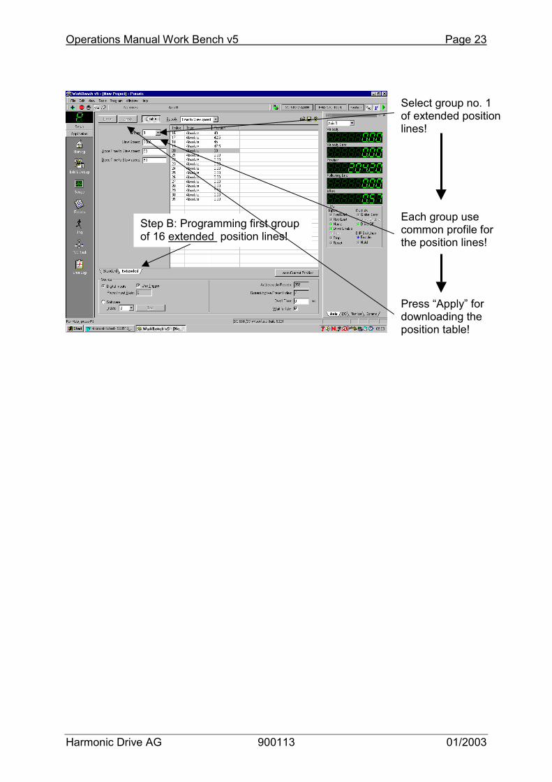
Step B: Programming first group of 16 extended position lines!
Select group no. 1 of extended position lines!
Each group use common profile for the position lines!
Press “Apply” for downloading the position table!
Page 24 Operations Manual Work Bench v5
Harmonic Drive AG 900113 01/2003
8 Tuning Guidelines Tuning philosophy:
- Executing Auto-tune under no load condition as a final step of drive commissioning
- Executing Fine-tune at load condition after having checked the system wiring and mechanical assembly
Tuning rule:
- First: tune the current loop - Second: tune the velocity loop - Third: tune the position loop (only if position mode is applied)
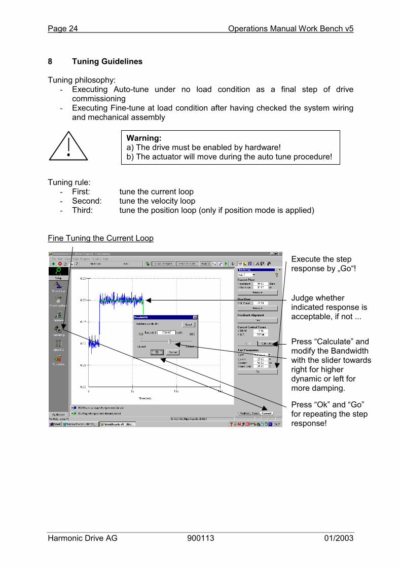
Fine Tuning the Current Loop
Warning: a) The drive must be enabled by hardware! b) The actuator will move during the auto tune procedure!
Execute the step response by „Go“!
Judge whether indicated response is acceptable, if not ...
Press “Calculate” and modify the Bandwidth with the slider towards right for higher dynamic or left for more damping.
Press “Ok” and “Go” for repeating the step response!
Operations Manual Work Bench v5 Page 25
Harmonic Drive AG 900113 01/2003
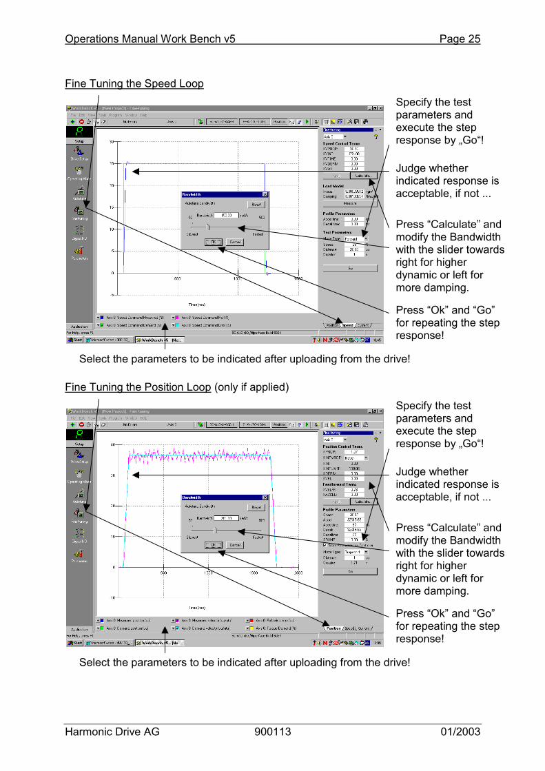
Fine Tuning the Speed Loop Fine Tuning the Position Loop (only if applied)
Specify the test parameters and execute the step response by „Go“!
Judge whether indicated response is acceptable, if not ...
Press “Calculate” and modify the Bandwidth with the slider towards right for higher dynamic or left for more damping.
Press “Ok” and “Go” for repeating the step response!
Specify the test parameters and execute the step response by „Go“!
Judge whether indicated response is acceptable, if not ...
Press “Calculate” and modify the Bandwidth with the slider towards right for higher dynamic or left for more damping.
Press “Ok” and “Go” for repeating the step response!
Select the parameters to be indicated after uploading from the drive!
Select the parameters to be indicated after uploading from the drive!

Page 26 Operations Manual Work Bench v5
Harmonic Drive AG 900113 01/2003
9 Data Backup 9.1 Generating a Parameter File a) Start Software by double click on icon „Work Bench v5“ at the desktop b) Start Menu Work Bench c) Select Controller
Click on „Scan“ and establish communication with the drive
„Only scan COM1“ in case COM1 on the PC is in use
Wait until SC-610 is indicated
Do not activate „Launch Commissioning Wizard“ and click on „Select“
Click on „Start New Project“
The data backup should be done after having done the basic and specific set-up including the fine-tuning!
Operations Manual Work Bench v5 Page 27
Harmonic Drive AG 900113 01/2003
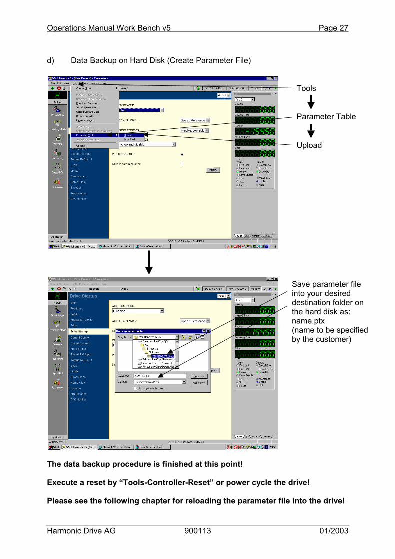
d) Data Backup on Hard Disk (Create Parameter File) The data backup procedure is finished at this point! Execute a reset by “Tools-Controller-Reset” or power cycle the drive! Please see the following chapter for reloading the parameter file into the drive!
Tools
Save parameter file into your desired destination folder on the hard disk as: name.ptx (name to be specified by the customer)
Parameter Table
Upload
Page 28 Operations Manual Work Bench v5
Harmonic Drive AG 900113 01/2003
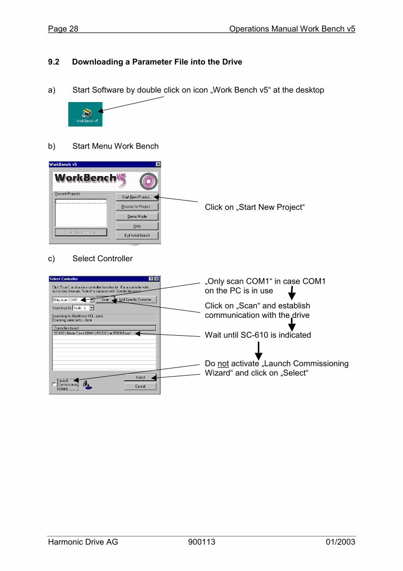
9.2 Downloading a Parameter File into the Drive a) Start Software by double click on icon „Work Bench v5“ at the desktop b) Start Menu Work Bench c) Select Controller
Click on „Scan“ and establish communication with the drive
„Only scan COM1“ in case COM1 on the PC is in use
Wait until SC-610 is indicated
Do not activate „Launch Commissioning Wizard“ and click on „Select“
Click on „Start New Project“
Operations Manual Work Bench v5 Page 29
Harmonic Drive AG 900113 01/2003
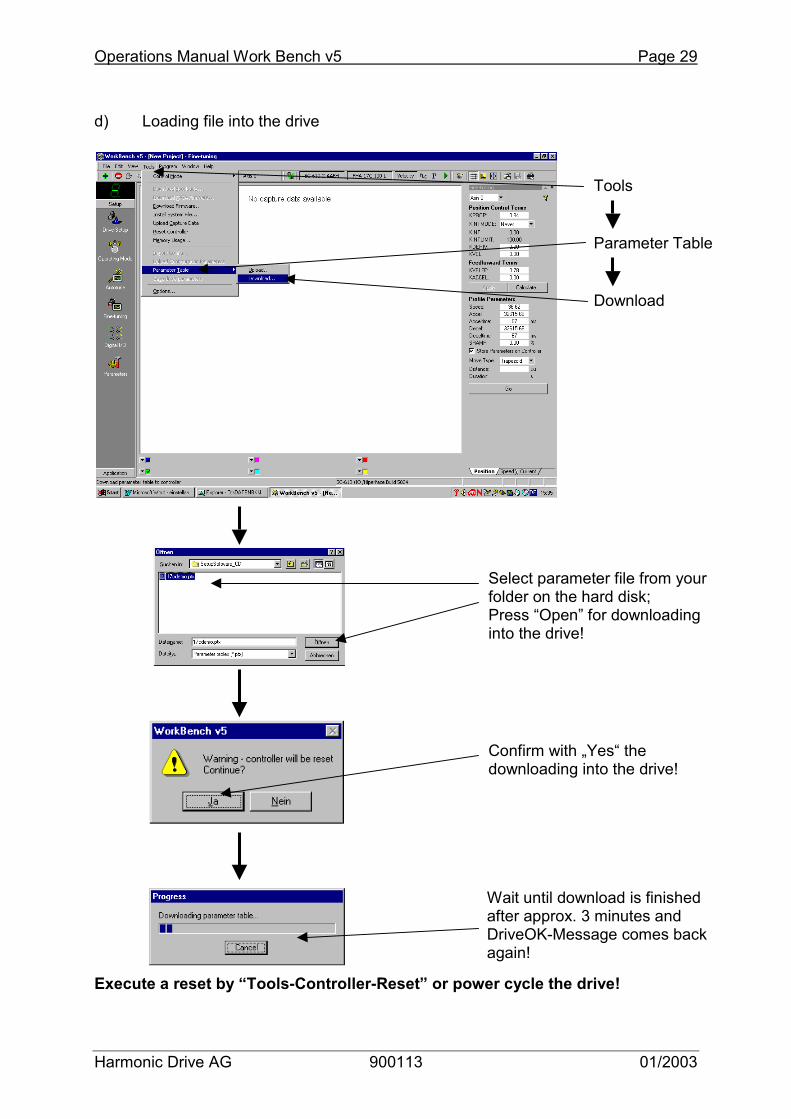
d) Loading file into the drive Execute a reset by “Tools-Controller-Reset” or power cycle the drive!
Tools
Parameter Table
Download
Select parameter file from your folder on the hard disk; Press “Open” for downloading into the drive!
Confirm with „Yes“ the downloading into the drive!
Wait until download is finished after approx. 3 minutes and DriveOK-Message comes back again!

Page 30 Operations Manual Work Bench v5
Harmonic Drive AG 900113 01/2003
10 Downloading a new Firmware Version a) Start Software by double click on icon „Work Bench v5“ at the desktop b) Start Menu Work Bench c) Select Controller
Click on „Scan“ and establish communication with the drive
„Only scan COM1“ in case COM1 on the PC is in use
Wait until SC-610 is indicated
Do not activate „Launch Commissioning Wizard“ and click on „Select“
Click on „Start New Project“

Operations Manual Work Bench v5 Page 31
Harmonic Drive AG 900113 01/2003
d) Proving Firmware and Download only at deviation from table below Actual configuration as per December 2002:
Drive Type Firmware Connector X12
Pins on X8
SC-610-X-XXAH SC-610/Hiperface Build 5104 No 15 SC-610-X-XXBH SC-610/IO/Hiperface Build 5104 Yes 15 SC-610-X-XXAR SC-610/Resolver Build 5104 No 9 SC-610-X-XXBR SC-610/IO/Resolver Build 5104 Yes 9
Select menu „Tools“
Execute „Download Firmware“
Page 32 Operations Manual Work Bench v5
Harmonic Drive AG 900113 01/2003
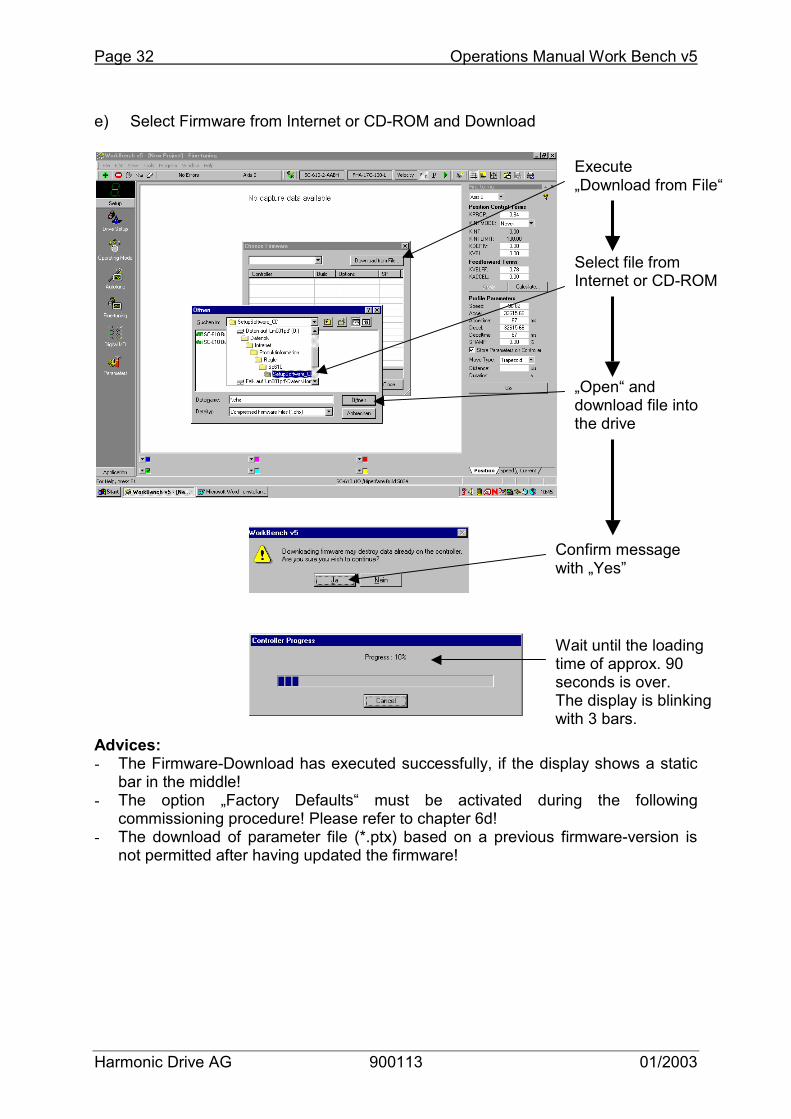
e) Select Firmware from Internet or CD-ROM and Download Advices: - The Firmware-Download has executed successfully, if the display shows a static
bar in the middle! - The option „Factory Defaults“ must be activated during the following
commissioning procedure! Please refer to chapter 6d! - The download of parameter file (*.ptx) based on a previous firmware-version is
not permitted after having updated the firmware!
Execute „Download from File“
Select file from Internet or CD-ROM
„Open“ and download file into the drive
Confirm message with „Yes”
Wait until the loading time of approx. 90 seconds is over. The display is blinking with 3 bars.
Operations Manual Work Bench v5 Page 33
Harmonic Drive AG 900113 01/2003
11 Programming with ActiveX-Controls 11.1 General description
ActiveX controls, formerly known as OLE controls or OCX controls, are components (or objects) that can be inserted into an application to reuse packaged functionality. For example, the ActiveX controls that are included with these servo controllers allow PC applications to communicate with controllers to allow complete machine control from a PC. A key advantage of ActiveX controls is that they can be used in applications written in many programming languages, including development environments such as:
��Microsoft Visual C++ ��Microsoft Visual Basic ��Borland Delphi ��National Instruments Lab View
Any development environment that supports ActiveX controls can use the SC610-ActiveX-control making it a very versatile interface to the controller.
The use of ActiveX-Controls is reserved for qualified engineers who are familiar with this technology! It is upon the user to develop and maintain the code sinceHarmonic Drive does not take over any responsibility in thefinal operation and possible malfunctions!
Page 34 Operations Manual Work Bench v5
Harmonic Drive AG 900113 01/2003
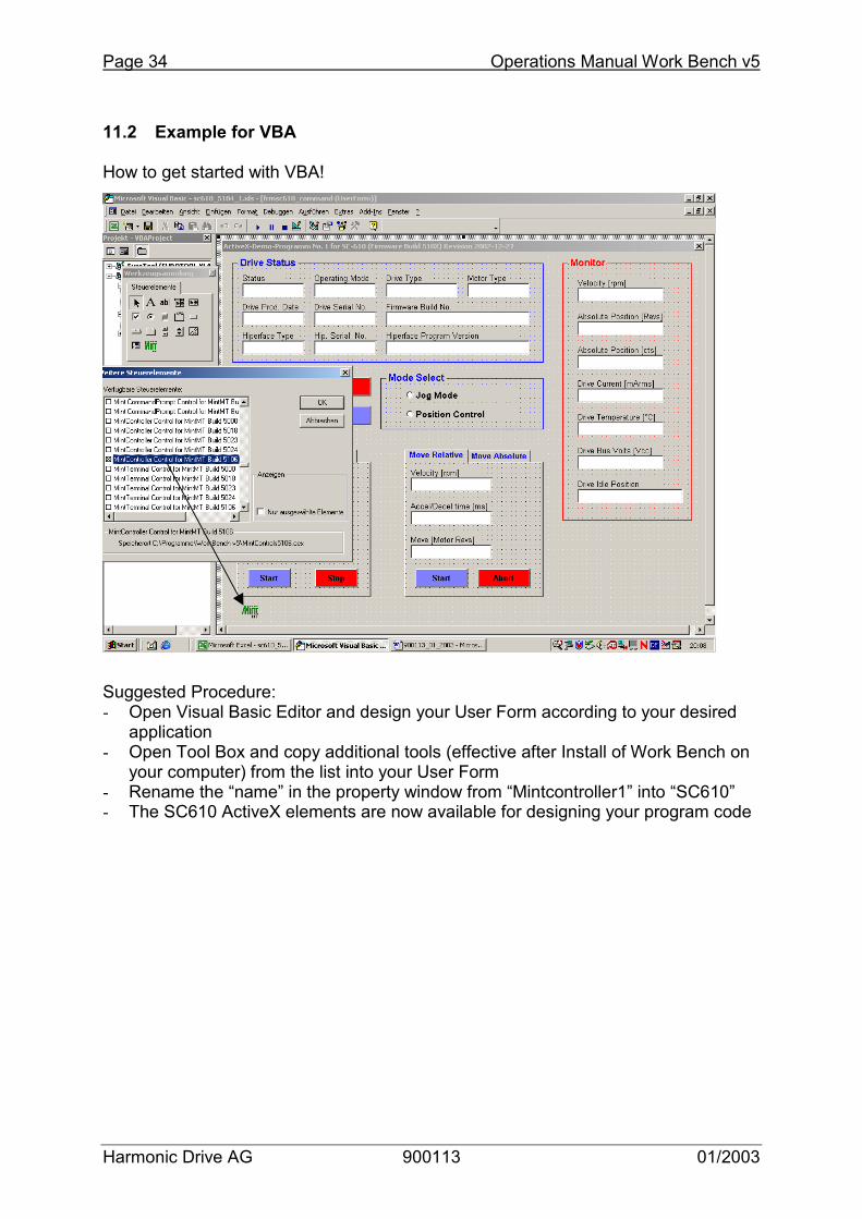
11.2 Example for VBA How to get started with VBA! Suggested Procedure: - Open Visual Basic Editor and design your User Form according to your desired
application - Open Tool Box and copy additional tools (effective after Install of Work Bench on
your computer) from the list into your User Form - Rename the “name” in the property window from “Mintcontroller1” into “SC610” - The SC610 ActiveX elements are now available for designing your program code

Operations Manual Work Bench v5 Page 35
Harmonic Drive AG 900113 01/2003
Example for a User Form in VBA attached to an Excel-file! Example for a VBA-code (extract only) attached to an Excel-file!