service manual - diagramas dediagramasde.com/diagramas/otros2/xerox-m15 samsung-5315.pdfdigital...
TRANSCRIPT
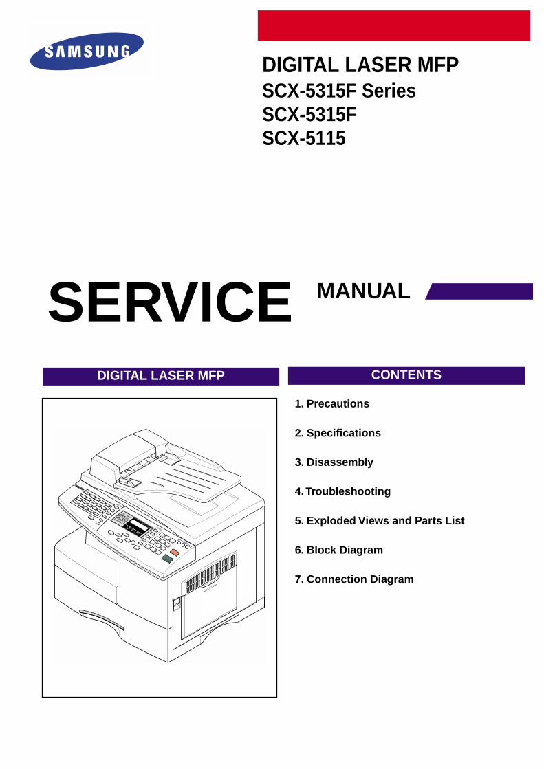
DIGITAL LASER MFPSCX-5315F SeriesSCX-5315FSCX-5115
1. Precautions
2. Specifications
3. Disassembly
4. Troubleshooting
5. Exploded Views and Parts List
6. Block Diagram
7. Connection Diagram
DIGITAL LASER MFP CONTENTS
SERVICE MANUAL
Specification
Samsung Electronics 2-1
2. Specification
Specifications are correct at the time of printing. Product specifications are subject to change without notice. See below for product specifications.
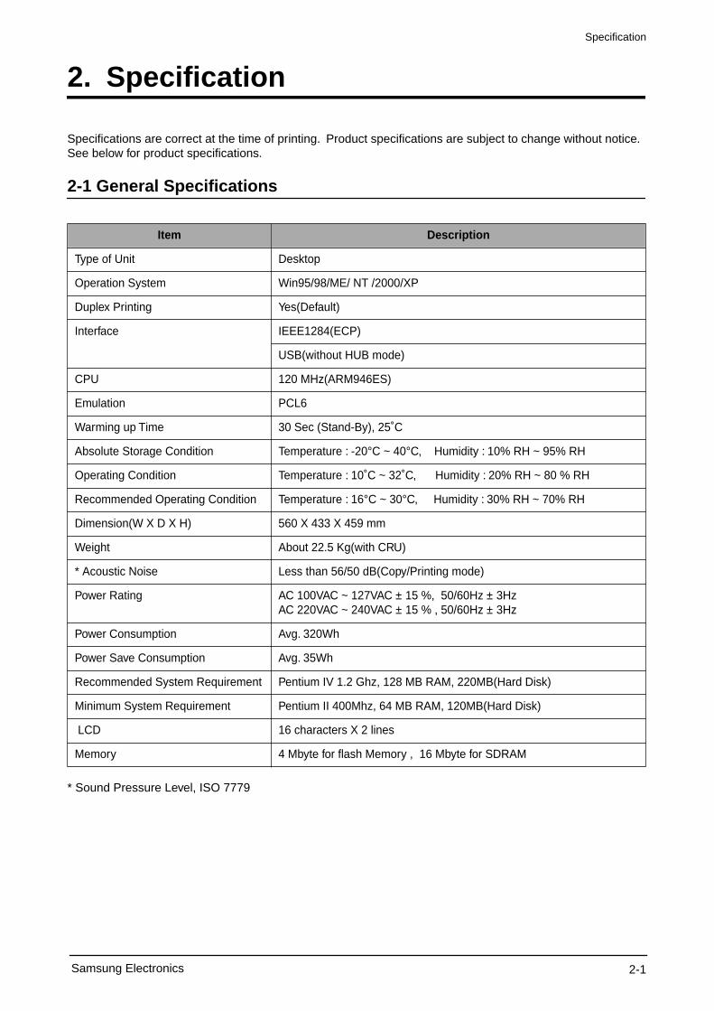
2-1 General Specifications
* Sound Pressure Level, ISO 7779
Item Description
Type of Unit Desktop
Operation System Win95/98/ME/ NT /2000/XP
Duplex Printing Yes(Default)
Interface IEEE1284(ECP)
USB(without HUB mode)
CPU 120 MHz(ARM946ES)
Emulation PCL6
Warming up Time 30 Sec (Stand-By), 25˚C
Absolute Storage Condition Temperature : -20°C ~ 40°C, Humidity : 10% RH ~ 95% RH
Operating Condition Temperature : 10˚C ~ 32˚C, Humidity : 20% RH ~ 80 % RH
Recommended Operating Condition Temperature : 16°C ~ 30°C, Humidity : 30% RH ~ 70% RH
Dimension(W X D X H) 560 X 433 X 459 mm
Weight About 22.5 Kg(with CRU)
* Acoustic Noise Less than 56/50 dB(Copy/Printing mode)
Power Rating AC 100VAC ~ 127VAC ± 15 %, 50/60Hz ± 3HzAC 220VAC ~ 240VAC ± 15 % , 50/60Hz ± 3Hz
Power Consumption Avg. 320Wh
Power Save Consumption Avg. 35Wh
Recommended System Requirement Pentium IV 1.2 Ghz, 128 MB RAM, 220MB(Hard Disk)
Minimum System Requirement Pentium II 400Mhz, 64 MB RAM, 120MB(Hard Disk)
LCD 16 characters X 2 lines
Memory 4 Mbyte for flash Memory , 16 Mbyte for SDRAM
Specification
Samsung Electronics2-2
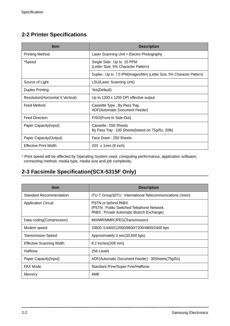
2-2 Printer Specifications
* Print speed will be affected by Operating System used, computing performance, application software, connecting method, media type, media size and job complexity.
2-3 Facsimile Specification(SCX-5315F Only)
Item Description
Printing Method Laser Scanning Unit + Electro Photography
*Speed Single Side : Up to 15 PPM(Letter Size, 5% Character Pattern)
Duplex : Up to 7.5 IPM(Images/Min) (Letter Size, 5% Character Pattern)
Source of Light LSU(Laser Scanning Unit)
Duplex Printing Yes(Default)
Resolution(Horizontal X Vertical) Up to 1200 x 1200 DPI effective output
Feed Method Cassette Type , By Pass Tray, ADF(Automatic Document Feeder)
Feed Direction FISO(Front-In Side-Out)
Paper Capacity(Input) Cassette : 550 SheetsBy Pass Tray : 100 Sheets(based on 75g/ß
≥
, 20lb)
Paper Capacity(Output) Face Down : 250 Sheets
Effective Print Width 203 ± 1mm (8 inch)
Item Description
Standard Recommendation ITU-T Group3(ITU : International Telecommunications Union)
Application Circuit PSTN or behind PABX(PSTN : Public Switched Telephone Network. PABX : Private Automatic Branch Exchange)
Data coding(Compression) MH/MR/MMR/JPEG(Transmission)
Modem speed 33600 /14400/12000/9600/7200/4800/2400 bps
Transmission Speed Approximately 3 sec(33,600 bps)
Effective Scanning Width 8.2 inches(208 mm)
Halftone 256 Levels
Paper Capacity(Input) ADF(Automatic Document Feeder) : 30Sheets(75g/ß
≥
)
FAX Mode Standard /Fine/Super Fine/Halftone
Memory 4MB
Specification
Samsung Electronics 2-3
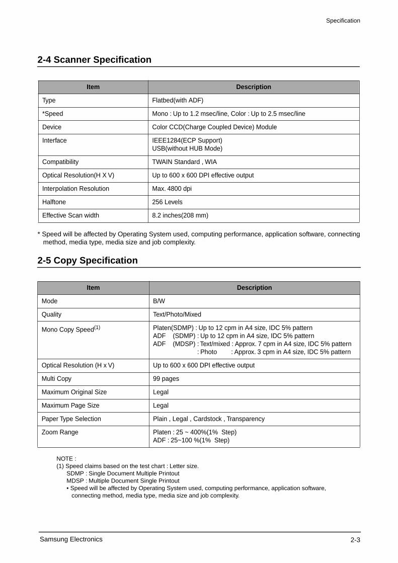
2-4 Scanner Specification
* Speed will be affected by Operating System used, computing performance, application software, connecting method, media type, media size and job complexity.
2-5 Copy Specification
NOTE : (1) Speed claims based on the test chart : Letter size. SDMP : Single Document Multiple Printout MDSP : Multiple Document Single Printout • Speed will be affected by Operating System used, computing performance, application software, connecting method, media type, media size and job complexity.
Item Description
Type Flatbed(with ADF)
*Speed Mono : Up to 1.2 msec/line, Color : Up to 2.5 msec/line
Device Color CCD(Charge Coupled Device) Module
Interface IEEE1284(ECP Support) USB(without HUB Mode)
Compatibility TWAIN Standard , WIA
Optical Resolution(H X V) Up to 600 x 600 DPI effective output
Interpolation Resolution Max. 4800 dpi
Halftone 256 Levels
Effective Scan width 8.2 inches(208 mm)
Item Description
Mode B/W
Quality Text/Photo/Mixed
Mono Copy Speed
(1)
Platen(SDMP) : Up to 12 cpm in A4 size, IDC 5% patternADF (SDMP) : Up to 12 cpm in A4 size, IDC 5% patternADF (MDSP) : Text/mixed : Approx. 7 cpm in A4 size, IDC 5% pattern : Photo : Approx. 3 cpm in A4 size, IDC 5% pattern
Optical Resolution (H x V) Up to 600 x 600 DPI effective output
Multi Copy 99 pages
Maximum Original Size Legal
Maximum Page Size Legal
Paper Type Selection Plain , Legal , Cardstock , Transparency
Zoom Range Platen : 25 ~ 400%(1% Step)ADF : 25~100 %(1% Step)
Specification
Samsung Electronics2-4
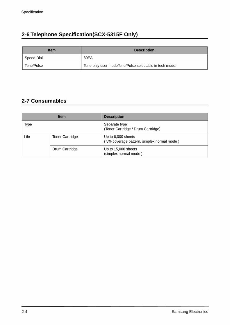
2-6 Telephone Specification(SCX-5315F Only)
2-7 Consumables
Item Description
Speed Dial 80EA
Tone/Pulse Tone only user modeTone/Pulse selectable in tech mode.
Item Description
Type Separate type(Toner Cartridge / Drum Cartridge)
Life Toner Cartridge Up to 6,000 sheets ( 5% coverage pattern, simplex normal mode )
Drum Cartridge Up to 15,000 sheets (simplex normal mode )

T I D I
This service manual is also provided on the web, the ITSELF system Samsung Electronics Co., Ltd.“http://itself.sec.samsung.co.kr”
© Samsung Electronics Co.,Ltd. JULY 2003 Printed in Korea.VERSION NO. : 1.00 CODE : JC-0086A
This Service Manual is a property of Samsung Electronics Co.,Ltd. Any unauthorized use of Manual can be punished under applicable International and/or domestic law.
Disassembly and Reassembly
Samsung Electronics 3-1
3. Disassembly and Reassembly
3-1 General Precautions on Disassembly
When you disassemble and reassemble components, you must use extreme caution. The close proximity of cables to moving parts makes proper routing a must. If components are removed, any cables disturbed by the procedure must be restored as close as possible to their original positions. Before removing any component from the machine, note the cable routing that will be affected.
Whenever servicing the machine, you must carry out the following :
1. Check to verify that documents are not stored in memory.
2. Unplug the power cord.
3. Use a flat and clean surface.
4. Replace only with authorized components.
5. Take care when removing plastic component-do not force.
6. Make sure all components are in their proper position.
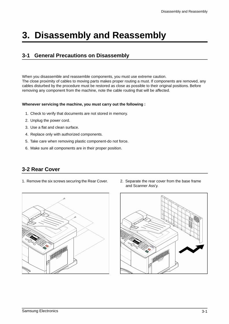
3-2 Rear Cover
1. Remove the six screws securing the Rear Cover.
2. Separate the rear cover from the base frame and Scanner Ass'y.
Disassembly and Reassembly
3-2 Samsung Electronics
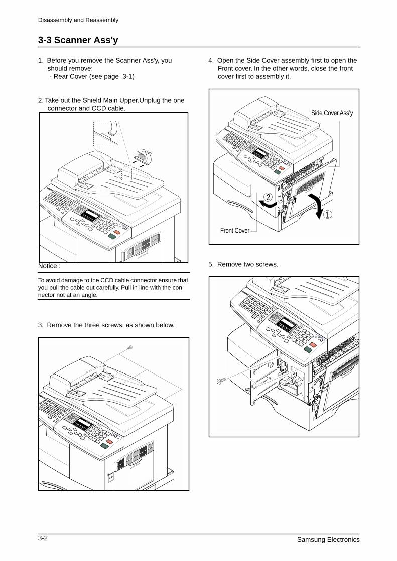
3-3 Scanner Ass'y
1. Before you remove the Scanner Ass'y, you should remove: - Rear Cover (see page 3-1)
2. Take out the Shield Main Upper.Unplug the one connector and CCD cable.
Notice :
To avoid damage to the CCD cable connector ensure that you pull the cable out carefully. Pull in line with the con-
nector not at an angle.
3. Remove the three screws, as shown below.
4. Open the Side Cover assembly first to open the Front cover. In the other words, close the front cover first to assembly it.
5. Remove two screws.
Side Cover Ass’y
Front Cover
1
2
Disassembly and Reassembly
Samsung Electronics 3-3
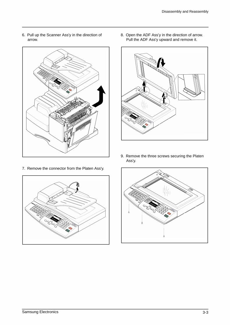
6. Pull up the Scanner Ass'y in the direction of arrow.
7. Remove the connector from the Platen Ass'y.
8. Open the ADF Ass’y in the direction of arrow. Pull the ADF Ass'y upward and remove it.
9. Remove the three screws securing the Platen Ass'y.
Disassembly and Reassembly
3-4 Samsung Electronics
10. Pull the OPE Ass'y and unplug the one connector.
11. Remove the five screws securing the Platen Ass'y.
12. Unlatch the Scan Upper Ass'y securing the glass and remove it.
Notice :
When dismantling the Scan Assy ensure your work area is clean. Dirt or dust on the scan head can lead to a deg-
radation in scanned image quality.
13. Remove the two scews and pull the Dummy Upper Ass’y.
Dummy Upper Ass’y
Disassembly and Reassembly
Samsung Electronics 3-5
14. Remove the four screws and Channel Base Frame.
15. Remove the five screws and Dummy Scan-Lower.
16. Remove the CCD cable.
17. Pull up the Shaft CCD and take out the Scanner Module.
18. Remove three screws and take out the Motor Bracket.
Channel Base Frame
Cover Scan Lower
Cover Dummy Lower
CCD Cable
Scanner Module
Shaft CCD
Belt
Pully
Disassembly and Reassembly
3-6 Samsung Electronics
19. Remove the OPE Harness from the Platen PBA. Remove two screws and take out the Platen PBA.
Notice :
Take special care when reassembling the CCD Moduleonto the Platen Ass'y. The CCD Module is located just tothe right side the Belt Tension Spring as shown below.
Platen PBA
OPE HarnessScanner Module
Belt Tension Spring
Disassembly and Reassembly
Samsung Electronics 3-7
3-4 ADF Ass'y
1. Before you remove the ADF Ass'y, you should remove:
- Rear Cover (see page 3-1) - Scanner Ass'y (see page 3-2)
2. Remove the five screws from the Platen Cover.
3. Open the Cover. Remove Cover Side R. Unlatch the Side Cover L by pushing the catch hooked to the Platen Cover using a sharp tool and remove Side Cover L.
4. Pull the ADF Ass'y upward and remove it.
5. Tack out he Open Cover.
Platen Cover Ass’y
Side Cover L
Cover Open
Side Cover R
Platen Cover Ass’y
Open Cover
Disassembly and Reassembly
3-8 Samsung Electronics
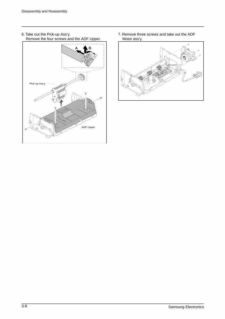
6. Take out the Pick-up Ass’y. Remove the four screws and the ADF Upper.
7. Remove three screws and take out the ADF Motor ass'y.
Pick-up Ass’y
ADF Upper

Disassembly and Reassembly
Samsung Electronics 3-9
3-5 OPE Ass'y
1. Before you remove the OPE Ass'y, you should remove: - Rear Cover (see page 3-1) - Scanner Ass'y (see page 3-2)
2. Remove ten screws securing the OPE PBA and the LCD Module from the OPE Cover.
3. Remove the contact rubbers from the unit.
4. Remove the key pad from the unit.
Caution
The above information is for the SCX-5315F model. For the SCX-5115 model, the OPE Ass’y is slightly differ-
ent, prats maked “a” are not fitted.
Disassembly and Reassembly
3-10 Samsung Electronics
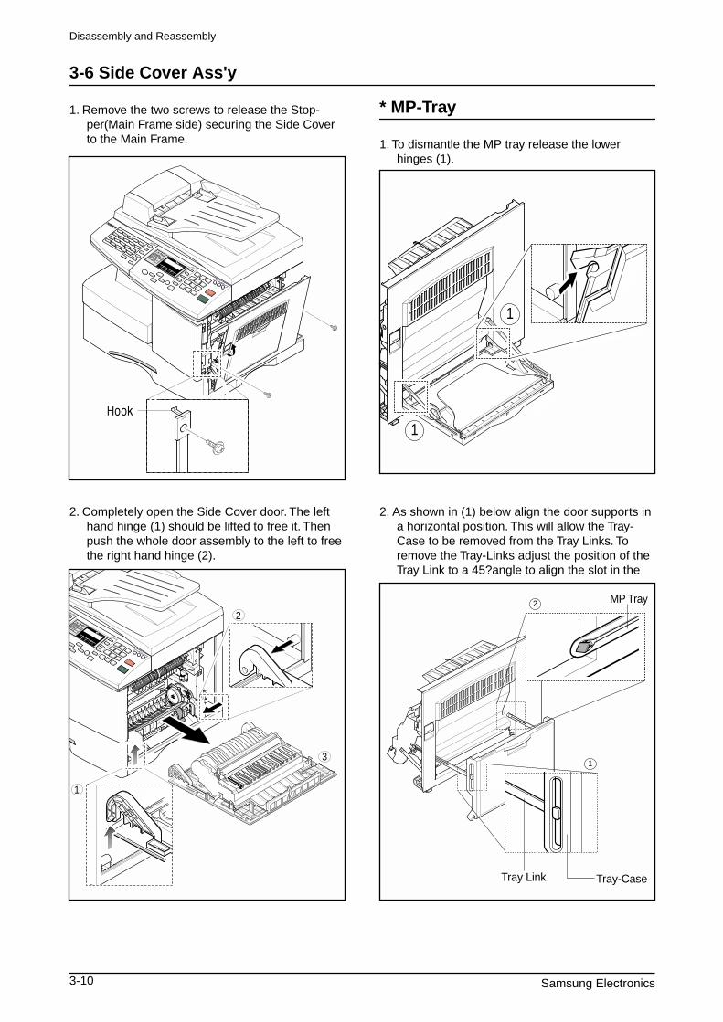
3-6 Side Cover Ass'y
1. Remove the two screws to release the Stop-per(Main Frame side) securing the Side Cover to the Main Frame.
2. Completely open the Side Cover door. The left hand hinge (1) should be lifted to free it. Then push the whole door assembly to the left to free the right hand hinge (2).
* MP-Tray
1. To dismantle the MP tray release the lower hinges (1).
2. As shown in (1) below align the door supports in a horizontal position. This will allow the Tray-Case to be removed from the Tray Links. To remove the Tray-Links adjust the position of the Tray Link to a 45?angle to align the slot in the
Tray Link Tray-Case
MP Tray
1
2
1
1
1
2
3
Disassembly and Reassembly
Samsung Electronics 3-11
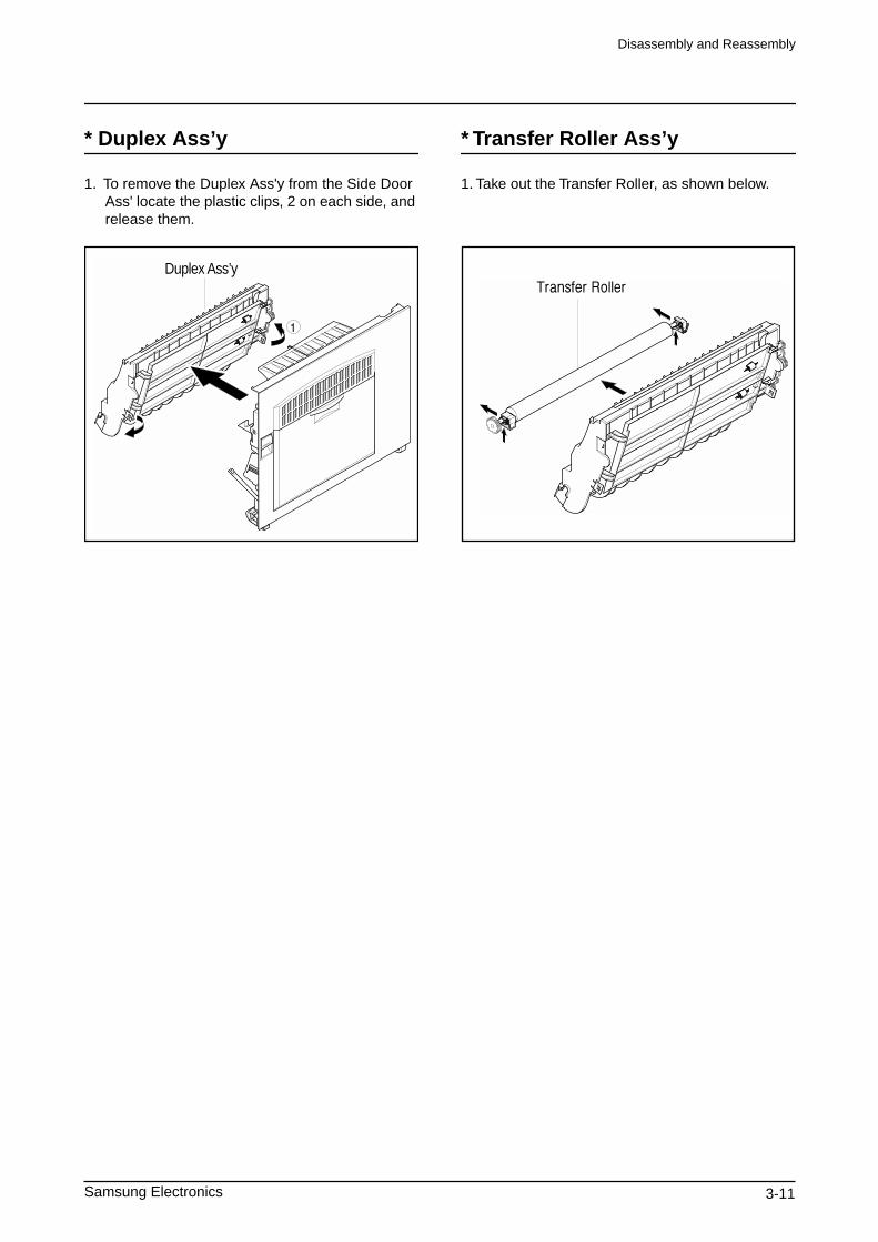
* Duplex Ass’y
1. To remove the Duplex Ass'y from the Side Door Ass' locate the plastic clips, 2 on each side, and release them.
Duplex Ass’y
* Transfer Roller Ass’y
1. Take out the Transfer Roller, as shown below.
Disassembly and Reassembly
3-12 Samsung Electronics
3-7 Fuser Ass'y
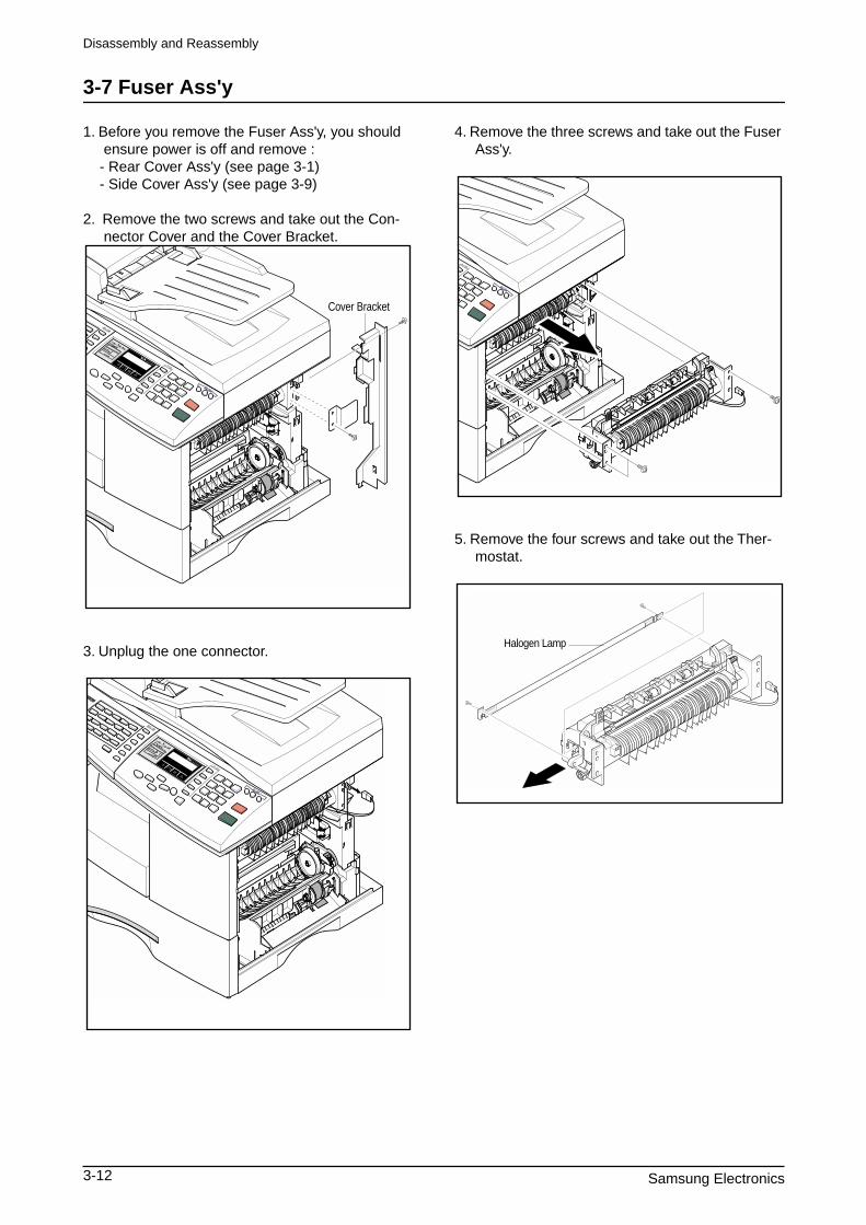
1. Before you remove the Fuser Ass'y, you should ensure power is off and remove :
- Rear Cover Ass'y (see page 3-1) - Side Cover Ass'y (see page 3-9)
2. Remove the two screws and take out the Con-nector Cover and the Cover Bracket.
3. Unplug the one connector.
4. Remove the three screws and take out the Fuser Ass'y.
5. Remove the four screws and take out the Ther-mostat.
Cover Bracket
Halogen Lamp
Disassembly and Reassembly
Samsung Electronics 3-13
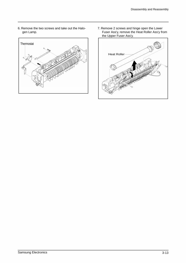
6. Remove the two screws and take out the Halo-gen Lamp.
7. Remove 2 screws and hinge open the Lower Fuser Ass'y, remove the Heat Roller Ass'y from the Upper Fuser Ass'y.
Thermostat
Heat Roller
Disassembly and Reassembly
3-14 Samsung Electronics
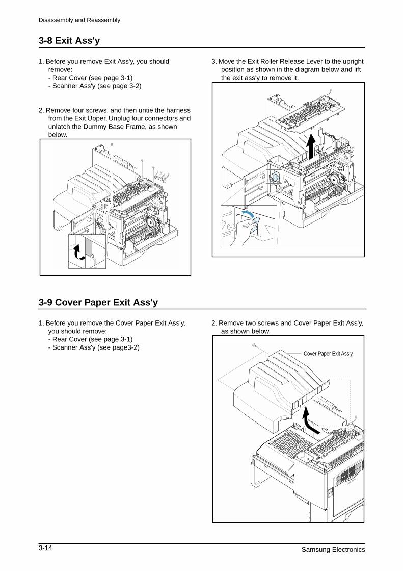
3-8 Exit Ass'y
1. Before you remove Exit Ass'y, you should remove: - Rear Cover (see page 3-1) - Scanner Ass'y (see page 3-2)
2. Remove four screws, and then untie the harness from the Exit Upper. Unplug four connectors and unlatch the Dummy Base Frame, as shown below.
3. Move the Exit Roller Release Lever to the upright position as shown in the diagram below and lift the exit ass'y to remove it.
3-9 Cover Paper Exit Ass'y
1. Before you remove the Cover Paper Exit Ass'y, you should remove: - Rear Cover (see page 3-1) - Scanner Ass'y (see page3-2)
2. Remove two screws and Cover Paper Exit Ass'y, as shown below.
Cover Paper Exit Ass’y
Disassembly and Reassembly
Samsung Electronics 3-15
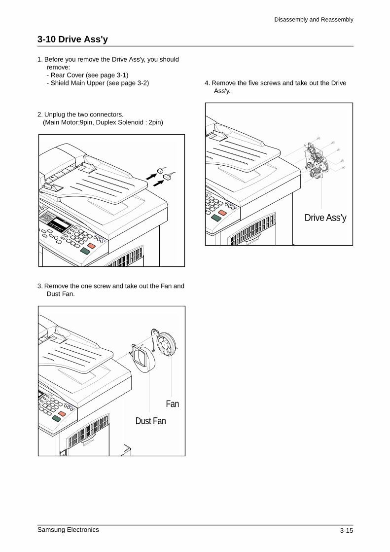
3-10 Drive Ass'y
1. Before you remove the Drive Ass'y, you should remove: - Rear Cover (see page 3-1) - Shield Main Upper (see page 3-2)
2. Unplug the two connectors. (Main Motor:9pin, Duplex Solenoid : 2pin)
3. Remove the one screw and take out the Fan and Dust Fan.
4. Remove the five screws and take out the Drive Ass'y.
Fan
Dust Fan
Drive Ass’y
Troubleshooting
Samsung Electronics 4-1
4. Maintenance & Troubleshooting
This chapter covers product maintenance, problem diagnosis and troubleshooting. It includes instructions for diagnosing and resolving print quality problems.This service manual covers both the SCX5315F and SCX5115 models. SCX5115 has printer, copier and scanner functions. The SCX5315F has all of the features of the SCX5115 and in addition has Fax capabilities.The manual contents are primarily written for the SCX5315F, where there are differences between the two models this is highlighted.
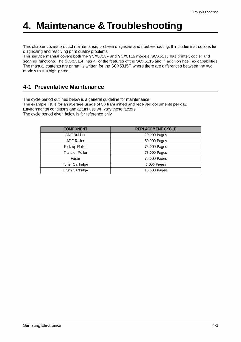
4-1 Preventative Maintenance
The cycle period outlined below is a general guideline for maintenance. The example list is for an average usage of 50 transmitted and received documents per day. Environmental conditions and actual use will vary these factors. The cycle period given below is for reference only.
COMPONENT REPLACEMENT CYCLE
ADF Rubber 20,000 Pages
ADF Roller 50,000 Pages
Pick-up Roller 75,000 Pages
Transfer Roller 75,000 Pages
Fuser 75,000 Pages
Toner Cartridge 6,000 Pages
Drum Cartridge 15,000 Pages
Troubleshooting
4-2 Samsung Electronics
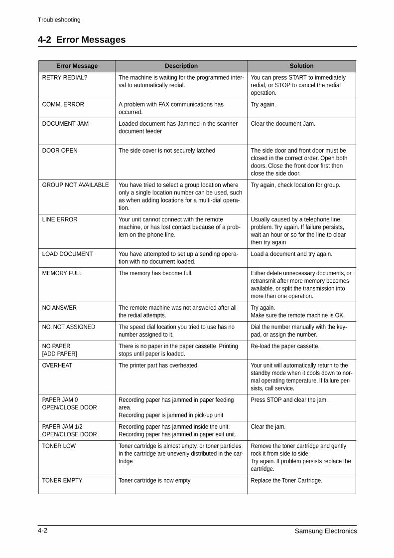
4-2 Error Messages
Error Message Description Solution
RETRY REDIAL? The machine is waiting for the programmed inter-val to automatically redial.
You can press START to immediately redial, or STOP to cancel the redial operation.
COMM. ERROR A problem with FAX communications has occurred.
Try again.
DOCUMENT JAM Loaded document has Jammed in the scanner document feeder
Clear the document Jam.
DOOR OPEN The side cover is not securely latched The side door and front door must beclosed in the correct order. Open bothdoors. Close the front door first thenclose the side door.
GROUP NOT AVAILABLE You have tried to select a group location where only a single location number can be used, such as when adding locations for a multi-dial opera-tion.
Try again, check location for group.
LINE ERROR Your unit cannot connect with the remote machine, or has lost contact because of a prob-lem on the phone line.
Usually caused by a telephone line problem. Try again. If failure persists, wait an hour or so for the line to clear then try again
LOAD DOCUMENT You have attempted to set up a sending opera-tion with no document loaded.
Load a document and try again.
MEMORY FULL The memory has become full. Either delete unnecessary documents, or retransmit after more memory becomes available, or split the transmission into more than one operation.
NO ANSWER The remote machine was not answered after all the redial attempts.
Try again.Make sure the remote machine is OK.
NO. NOT ASSIGNED The speed dial location you tried to use has no number assigned to it.
Dial the number manually with the key-pad, or assign the number.
NO PAPER[ADD PAPER]
There is no paper in the paper cassette. Printing stops until paper is loaded.
Re-load the paper cassette.
OVERHEAT The printer part has overheated. Your unit will automatically return to the standby mode when it cools down to nor-mal operating temperature. If failure per-sists, call service.
PAPER JAM 0OPEN/CLOSE DOOR
Recording paper has jammed in paper feeding area. Recording paper is jammed in pick-up unit
Press STOP and clear the jam.
PAPER JAM 1/2OPEN/CLOSE DOOR
Recording paper has jammed inside the unit.Recording paper has jammed in paper exit unit.
Clear the jam.
TONER LOW Toner cartridge is almost empty, or toner particles in the cartridge are unevenly distributed in the car-tridge
Remove the toner cartridge and gently rock it from side to side.Try again. If problem persists replace the cartridge.
TONER EMPTY Toner cartridge is now empty Replace the Toner Cartridge.
Troubleshooting
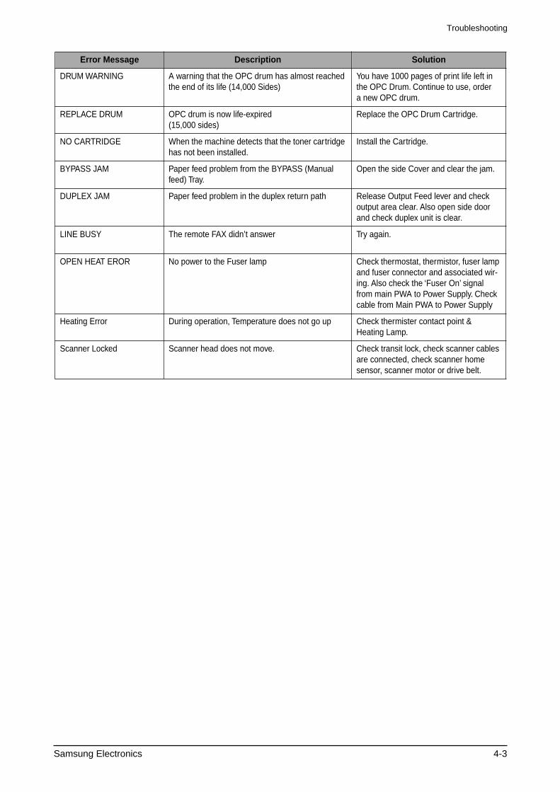
Samsung Electronics 4-3
DRUM WARNING A warning that the OPC drum has almost reached the end of its life (14,000 Sides)
You have 1000 pages of print life left inthe OPC Drum. Continue to use, ordera new OPC drum.
REPLACE DRUM OPC drum is now life-expired(15,000 sides)
Replace the OPC Drum Cartridge.
NO CARTRIDGE When the machine detects that the toner cartridge has not been installed.
Install the Cartridge.
BYPASS JAM Paper feed problem from the BYPASS (Manual feed) Tray.
Open the side Cover and clear the jam.
DUPLEX JAM Paper feed problem in the duplex return path Release Output Feed lever and checkoutput area clear. Also open side doorand check duplex unit is clear.
LINE BUSY The remote FAX didn’t answer Try again.
OPEN HEAT EROR No power to the Fuser lamp Check thermostat, thermistor, fuser lamp and fuser connector and associated wir-ing. Also check the ‘Fuser On’ signal from main PWA to Power Supply. Check cable from Main PWA to Power Supply
Heating Error During operation, Temperature does not go up Check thermister contact point &Heating Lamp.
Scanner Locked Scanner head does not move. Check transit lock, check scanner cables are connected, check scanner home sensor, scanner motor or drive belt.
Error Message Description Solution
Troubleshooting
4-4 Samsung Electronics
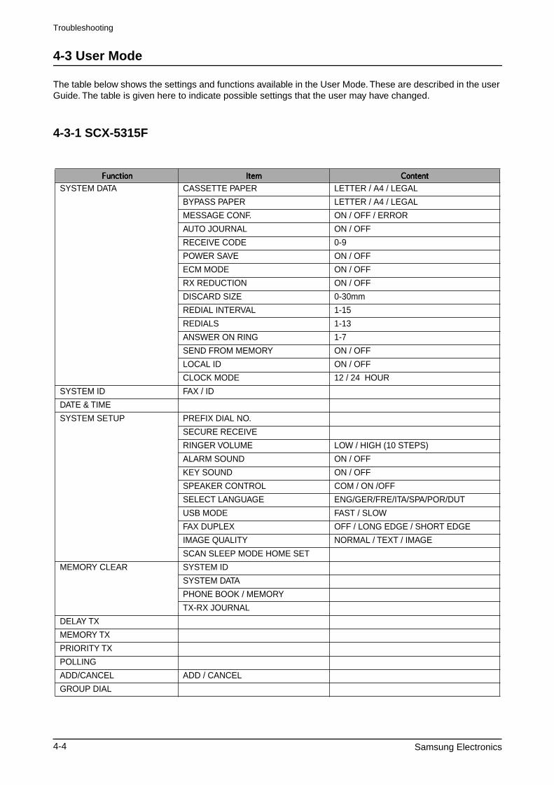
4-3 User Mode
The table below shows the settings and functions available in the User Mode. These are described in the user Guide. The table is given here to indicate possible settings that the user may have changed.
4-3-1 SCX-5315F
✳❑n❄❏❊on✳❑n❄❏❊on✳❑n❄❏❊on✳❑n❄❏❊on ✶❏❆m✶❏❆m✶❏❆m✶❏❆m ✰on❏❆n❏✰on❏❆n❏✰on❏❆n❏✰on❏❆n❏
SYSTEM DATA CASSETTE PAPER LETTER / A4 / LEGAL
BYPASS PAPER LETTER / A4 / LEGAL
MESSAGE CONF. ON / OFF / ERROR
AUTO JOURNAL ON / OFF
RECEIVE CODE 0-9
POWER SAVE ON / OFF
ECM MODE ON / OFF
RX REDUCTION ON / OFF
DISCARD SIZE 0-30mm
REDIAL INTERVAL 1-15
REDIALS 1-13
ANSWER ON RING 1-7
SEND FROM MEMORY ON / OFF
LOCAL ID ON / OFF
CLOCK MODE 12 / 24 HOUR
SYSTEM ID FAX / ID
DATE & TIME
SYSTEM SETUP PREFIX DIAL NO.
SECURE RECEIVE
RINGER VOLUME LOW / HIGH (10 STEPS)
ALARM SOUND ON / OFF
KEY SOUND ON / OFF
SPEAKER CONTROL COM / ON /OFF
SELECT LANGUAGE ENG/GER/FRE/ITA/SPA/POR/DUT
USB MODE FAST / SLOW
FAX DUPLEX OFF / LONG EDGE / SHORT EDGE
IMAGE QUALITY NORMAL / TEXT / IMAGE
SCAN SLEEP MODE HOME SET
MEMORY CLEAR SYSTEM ID
SYSTEM DATA
PHONE BOOK / MEMORY
TX-RX JOURNAL
DELAY TX
MEMORY TX
PRIORITY TX
POLLING
ADD/CANCEL ADD / CANCEL
GROUP DIAL
Troubleshooting
Samsung Electronics 4-5
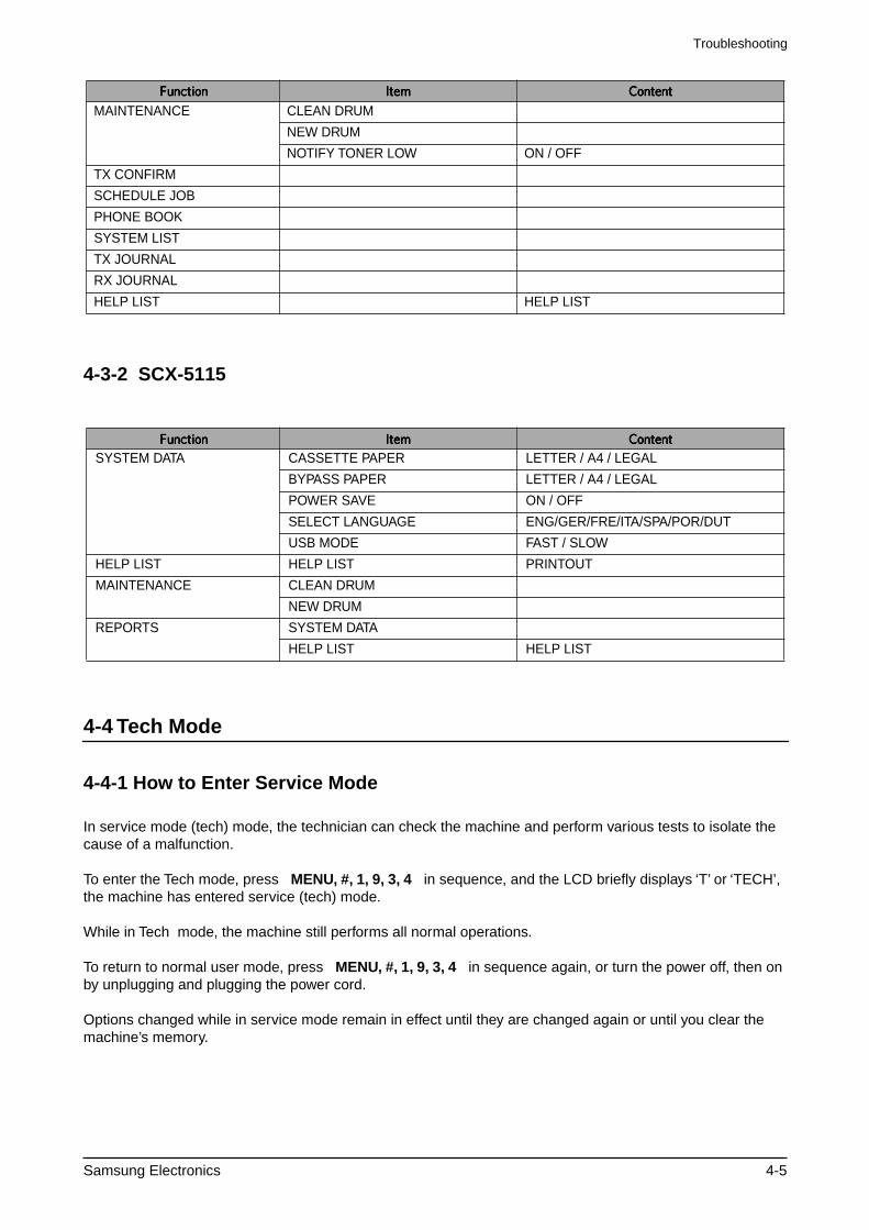
4-3-2 SCX-5115
4-4 Tech Mode
4-4-1 How to Enter Service Mode
In service mode (tech) mode, the technician can check the machine and perform various tests to isolate the cause of a malfunction.
To enter the Tech mode, press
MENU, #, 1, 9, 3, 4
in sequence, and the LCD briefly displays ‘T’ or ‘TECH’, the machine has entered service (tech) mode.
While in Tech mode, the machine still performs all normal operations.
To return to normal user mode, press
MENU, #, 1, 9, 3, 4
in sequence again, or turn the power off, then on by unplugging and plugging the power cord.
Options changed while in service mode remain in effect until they are changed again or until you clear the machine’s memory.
MAINTENANCE CLEAN DRUM
NEW DRUM
NOTIFY TONER LOW ON / OFF
TX CONFIRM
SCHEDULE JOB
PHONE BOOK
SYSTEM LIST
TX JOURNAL
RX JOURNAL
HELP LIST HELP LIST
✳❑n❄❏❊on✳❑n❄❏❊on✳❑n❄❏❊on✳❑n❄❏❊on ✶❏❆m✶❏❆m✶❏❆m✶❏❆m ✰on❏❆n❏✰on❏❆n❏✰on❏❆n❏✰on❏❆n❏
SYSTEM DATA CASSETTE PAPER LETTER / A4 / LEGAL
BYPASS PAPER LETTER / A4 / LEGAL
POWER SAVE ON / OFF
SELECT LANGUAGE ENG/GER/FRE/ITA/SPA/POR/DUT
USB MODE FAST / SLOW
HELP LIST HELP LIST PRINTOUT
MAINTENANCE CLEAN DRUM
NEW DRUM
REPORTS SYSTEM DATA
HELP LIST HELP LIST
✳❑n❄❏❊on✳❑n❄❏❊on✳❑n❄❏❊on✳❑n❄❏❊on ✶❏❆m✶❏❆m✶❏❆m✶❏❆m ✰on❏❆n❏✰on❏❆n❏✰on❏❆n❏✰on❏❆n❏
Troubleshooting
4-6 Samsung Electronics
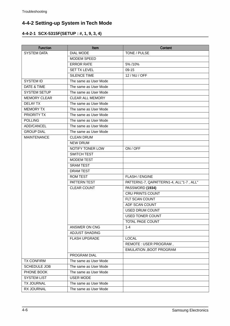
4-4-2 Setting-up System in Tech Mode
4-4-2-1 SCX-5315F(SETUP : #, 1, 9, 3, 4)
✳❑n❄❏❊on✳❑n❄❏❊on✳❑n❄❏❊on✳❑n❄❏❊on ✶❏❆m✶❏❆m✶❏❆m✶❏❆m ✰on❏❆n❏✰on❏❆n❏✰on❏❆n❏✰on❏❆n❏
SYSTEM DATA DIAL MODE TONE / PULSE
MODEM SPEED
ERROR RATE 5% /10%
SET TX LEVEL 09-15
SILENCE TIME 12 / NU / OFF
SYSTEM ID The same as User Mode
DATE & TIME The same as User Mode
SYSTEM SETUP The same as User Mode
MEMORY CLEAR CLEAR ALL MEMORY
DELAY TX The same as User Mode
MEMORY TX The same as User Mode
PRIORITY TX The same as User Mode
POLLING The same as User Mode
ADD/CANCEL The same as User Mode
GROUP DIAL The same as User Mode
MAINTENANCE CLEAN DRUM
NEW DRUM
NOTIFY TONER LOW ON / OFF
SWITCH TEST
MODEM TEST
SRAM TEST
DRAM TEST
ROM TEST FLASH / ENGINE
PATTERN TEST PATTERN1-7, QAPATTERN1-4, ALL"1-7 , ALL"
CLEAR COUNT PASSWORD
(1934)
CRU PRINTS COUNT
FLT SCAN COUNT
ADF SCAN COUNT
USED DRUM COUNT
USED TONER COUNT
TOTAL PAGE COUNT
ANSWER ON CNG 1-4
ADJUST SHADING
FLASH UPGRADE LOCAL
REMOTE : USER PROGRAM ,
EMULATION ,BOOT PROGRAM
PROGRAM DIAL
TX CONFIRM The same as User Mode
SCHEDULE JOB The same as User Mode
PHONE BOOK The same as User Mode
SYSTEM LIST USER MODE
TX JOURNAL The same as User Mode
RX JOURNAL The same as User Mode
Troubleshooting
Samsung Electronics 4-7
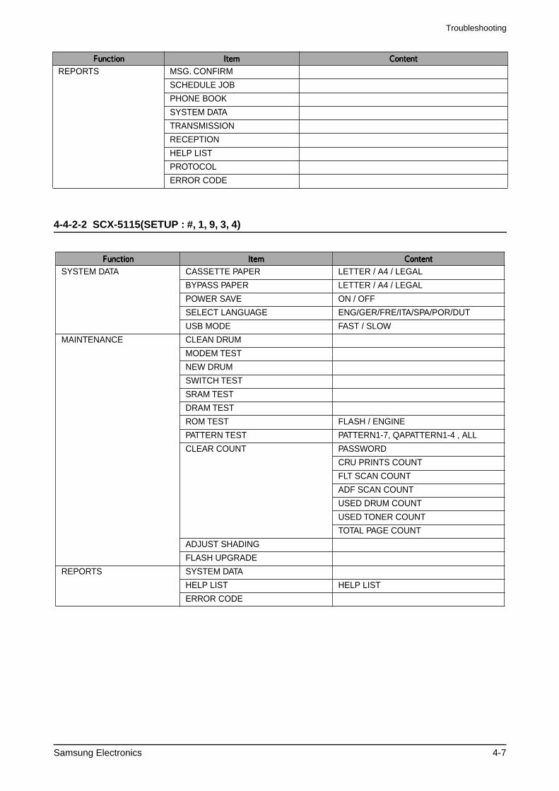
4-4-2-2 SCX-5115(SETUP : #, 1, 9, 3, 4)
REPORTS MSG. CONFIRM
SCHEDULE JOB
PHONE BOOK
SYSTEM DATA
TRANSMISSION
RECEPTION
HELP LIST
PROTOCOL
ERROR CODE
✳❑n❄❏❊on✳❑n❄❏❊on✳❑n❄❏❊on✳❑n❄❏❊on ✶❏❆m✶❏❆m✶❏❆m✶❏❆m ✰on❏❆n❏✰on❏❆n❏✰on❏❆n❏✰on❏❆n❏
SYSTEM DATA CASSETTE PAPER LETTER / A4 / LEGAL
BYPASS PAPER LETTER / A4 / LEGAL
POWER SAVE ON / OFF
SELECT LANGUAGE ENG/GER/FRE/ITA/SPA/POR/DUT
USB MODE FAST / SLOW
MAINTENANCE CLEAN DRUM
MODEM TEST
NEW DRUM
SWITCH TEST
SRAM TEST
DRAM TEST
ROM TEST FLASH / ENGINE
PATTERN TEST PATTERN1-7, QAPATTERN1-4 , ALL
CLEAR COUNT PASSWORD
CRU PRINTS COUNT
FLT SCAN COUNT
ADF SCAN COUNT
USED DRUM COUNT
USED TONER COUNT
TOTAL PAGE COUNT
ADJUST SHADING
FLASH UPGRADE
REPORTS SYSTEM DATA
HELP LIST HELP LIST
ERROR CODE
✳❑n❄❏❊on✳❑n❄❏❊on✳❑n❄❏❊on✳❑n❄❏❊on ✶❏❆m✶❏❆m✶❏❆m✶❏❆m ✰on❏❆n❏✰on❏❆n❏✰on❏❆n❏✰on❏❆n❏
Troubleshooting
4-8 Samsung Electronics
4-4-3 SYSTEM DATA
DIALING MODE
Select the dialing mode according to the user's line status.TONE: Electrical type of dialPULSE: Mechanical type of dial
SILENCE TIME
In ANS/FAX mode, after a call is picked up by the answering machine, the machine monitors the line. If a period of silence is detected on the line at any time, the call will be treated as a fax message and the machine begins receiving. Silence detection time is selectable between limited (about 12 seconds) and unlimited time.When '12 sec' is selected, the machine switches to receiving mode as soon as it detects a period of silence. When 'unlimited'is selected, the machine waits until the answering operation is concluded even though a period of silence is detected. After the answering operation is concluded, the machine switches to receiving mode.
SEND FAX LEVEL
You can set the level of the transmission signal. Typically, the Tx level should be under -12 dBm.
Caution: The Send Fax Level is set at the best condition in the shipment from factory. Never change settings arbitrarily.
ERROR RATE
Tou can set the Error Rate between 5% and 10%. During operation the set monitors the rror rate.When the rror rate approaches the preset value the machine automatically steps down the baude to 2400bps to ensure that the selected error rate is not exceeded.
MODEM SPEED
You can set the maximum modem speed. It is better left set 33.6Kbps (the default setting ).During call setup the baud rate is automatically adjusted to suite the slowest device. Only adjust this where the local line conditions are extremely poor.
4-4-4 MEMORY CLEAR
CLEAR ALL MEMORY
This function resets the system to its original factory settings. All settings entered in User Mode and Tech Mode are reset. This includes any User Phone Book entries, jobs stored in memory or received documents that have not been printed. If possible use the Control Panel software to download customer settings and phone book settings before carrying out a full reset.When diagnosing or testing a faulty unit this function is often useful. Be aware that all error reports are also cleared.
< Method >
1. Select the [MEMORY CLEAR] in TECH MODE.2. Push the ENTER button.3. Select your country.4. Push the ENTER button and all memory will be cleared.
NOTICE : Always perform a memory clear after replacing the main board or updating the firmware. Oth-erwise, the system may not operate properly.
Troubleshooting
Samsung Electronics 4-9
4-4-5 MAINTENANCE
CLEAN DRUM
Use this feature to remove toner particles remaining in the OPC drum unit.Use this feature when print quality falls or when marks or specks appear on the printout.You should perform this feature several times until a clean printout appears.The machine automatically pulls in a sheet of paper and prints out. Excess toner particles on the OPC drum surface are fixed to the paper.
FLASH UPGRADE
This function is used to update the system Firmware. There are 2 methods Local and Remote.More information can be found in the firmware upgrade section.
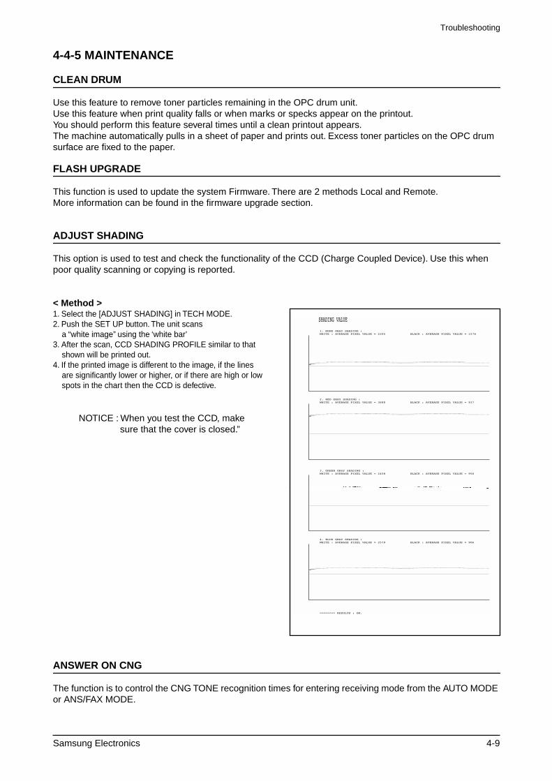
ADJUST SHADING
This option is used to test and check the functionality of the CCD (Charge Coupled Device). Use this when poor quality scanning or copying is reported.
< Method >
1. Select the [ADJUST SHADING] in TECH MODE.2. Push the SET UP button. The unit scans a “white image” using the ‘white bar’3. After the scan, CCD SHADING PROFILE similar to that shown will be printed out.4. If the printed image is different to the image, if the lines are significantly lower or higher, or if there are high or low spots in the chart then the CCD is defective.
NOTICE : When you test the CCD, make sure that the cover is closed.”
ANSWER ON CNG
The function is to control the CNG TONE recognition times for entering receiving mode from the AUTO MODE or ANS/FAX MODE.
Troubleshooting
4-10 Samsung Electronics
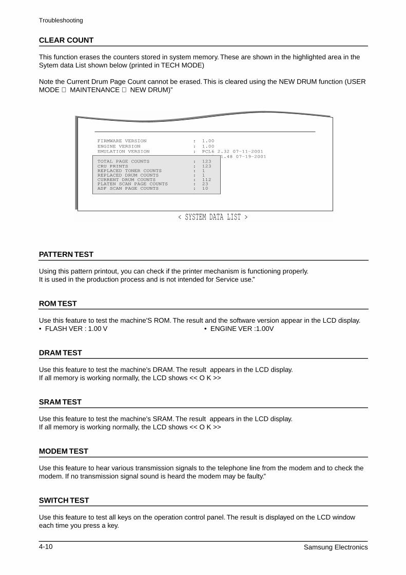
CLEAR COUNT
This function erases the counters stored in system memory. These are shown in the highlighted area in the Sytem data List shown below (printed in TECH MODE)
Note the Current Drum Page Count cannot be erased. This is cleared using the NEW DRUM function (USER MODE
⇒
MAINTENANCE
⇒
NEW DRUM)”
PATTERN TEST
Using this pattern printout, you can check if the printer mechanism is functioning properly.It is used in the production process and is not intended for Service use.”
ROM TEST
Use this feature to test the machine'S ROM. The result and the software version appear in the LCD display.• FLASH VER : 1.00 V • ENGINE VER :1.00V
DRAM TEST
Use this feature to test the machine's DRAM. The result appears in the LCD display.If all memory is working normally, the LCD shows << O K >>
SRAM TEST
Use this feature to test the machine's SRAM. The result appears in the LCD display.If all memory is working normally, the LCD shows << O K >>
MODEM TEST
Use this feature to hear various transmission signals to the telephone line from the modem and to check the modem. If no transmission signal sound is heard the modem may be faulty.”
SWITCH TEST
Use this feature to test all keys on the operation control panel. The result is displayed on the LCD window each time you press a key.
PCL5e 1.48 07-19-2001
FIRMWARE VERSION : 1.00ENGINE VERSION : 1.00
TOTAL PAGE COUNTS : 123
REPLACED TONER COUNTS : 1
EMULATION VERSION : PCL6 2.32 07-11-2001
CRU PRINTS : 123
REPLACED DRUM COUNTS : 1
PLATEN SCAN PAGE COUNTS : 23ADF SCAN PAGE COUNTS : 10
CURRENT DRUM COUNTS : 112
< SYSTEM DATA LIST >
Troubleshooting
Samsung Electronics 4-11
NOTIFY TONER LOW
With this feature enabled, when the toner becomes low, the toner low information will be sent to a specified contact point, for example, the service company. After you access this menu, select ON, and when the LCD-prompts, enter the name and the number of the contact point, the customer's fax number, the model name, and the serial number.”
PROGRAM DIAL
This is a special feature which allows the TECH USER to set parameters for a specific dialed location (which must be in the one touch or speed dial phone books). Parameters can be set to override the normal; default settings to enable the machine to cope with calls to destinations with known line problems”
4-4-6 REPORT/HELP
MSG. CONFIRM
It shows the result of the last send operation.
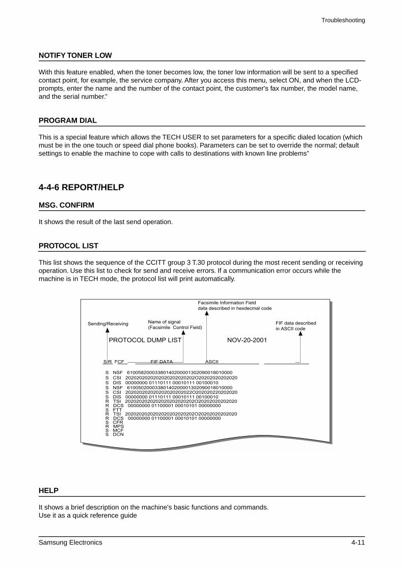
PROTOCOL LIST
This list shows the sequence of the CCITT group 3 T.30 protocol during the most recent sending or receiving operation. Use this list to check for send and receive errors. If a communication error occurs while the machine is in TECH mode, the protocol list will print automatically.
HELP
It shows a brief description on the machine's basic functions and commands.Use it as a quick reference guide
S NSF 61005820003380140200001302090018010000
S/R FCF FIF DATA! ASCII
S CSI 2020202020202020202020202O20202020202020
S CSI 202020202020202020202022O202020220202020
R TSI 2020202020202020202020202O20202020202020
S DIS 00000000 01110111 00010111 00100010
S DIS 00000000 01110111 00010111 00100010
R DCS 00000000 01100001 00010101 00000000
R TSI 2020202020202020202020202O20202020202020R DCS 00000000 01100001 00010101 00000000S CFRR MPSS MCFS DCN
S FTT
S NSF 61005020003380140200001302090018010000
PROTOCOL DUMP LIST NOV-20-2001
Sending/Receiving Name of signal(Facsimile Control Field)
Facsimile Information Fielddata described in hexdecmal code
FIF data describedin ASCII code
Troubleshooting
4-12 Samsung Electronics
RECEPTION
This journal shows information relating to document reception, the time and dates of up to 40 of the most recent documents received are stored.
TRANSMISSION
This journal shows information relating to document transmission, the time and dates of up to 40 of the most recent documents transmitted are stored.
SYSTEM DATA
This list provides a list of the user system data settings and tech mode settings.
PHONEBOOK
It lists all telephone numbers that have been stored in the machine.
SCHEDULE JOB
This list shows information relating to the documents currently stored for delayed transmission. It provides the operation number, starting time, type of operation, etc.
ERROR CODE
This list shows a list of errors that have occurred since the last memory clear.
4-4-7 Firmware UpgradeThis function is used to update the machines Firmwar, there are two Upgrade methods - local and remote.
4-4-7-1 Local Machine
RCP(Remote Control Panel) mode
This method is used with the machine connected using either a Parallel Port or USB Port to a PC and uses the RCP (Remote Control Panel) software to upgrade the Firmware.
< Method >
How to Update Firmware using RCP
1. Connect PC and Printer with Parallel Cable or USB Cable.2. Execute RCP and select Firmware Update. Current Firmware version and Emulation Version are displayed
on Current version window.3. The Firmware file must be stored on the PC, in a path close to the root of C:, ie C:\TEMP. Search for the
firmware file to use to update the machine by using the Browse Icon.4. Click the Update icon, the firmware file is transmitted to the Printer automatically and the printer is initialized
when the update is finished.5. Click the Refresh icon and check that the version number displayed matches the new firmware just loaded.”
Troubleshooting
Samsung Electronics 4-13
DOS Command mode
This method is just for Parallel Port. Connect to PC with Parallel cable and enter DOS Command to upgrade the Firmware.
< Method >a). You will need the following files:- down.bat, down_com.bin, fprt.exe, and “Rom File”: this is the firmware file to be loaded
into the printer. Save the files in the same folder, close to the root of C;, e.g. C\TEMPb). At a DOS prompt, input one of the commands shown below and press the enter key. The file will then be sent automatically to
the printer.c) There are two commands use the correct one depending on the printer status.
* when the printer is in the user mode and is in the normal ready condition: down "rom file"* When the product is been placed in the upgrade mode (TECH MODE → MAINTENANCE → FLASH UPGRADE → LOCAL)
fprt "rom file"d) Do not turn off the power while the upgrade is in process.”
4-4-7-2 Remote FAX
This function uses one fax machine already loaded with the latest firmware to upgrade one or more other remote machines of the same type using the telephone network.
< Method >1. Operate a fax with the latest firmware to prepare it to send the upgrade. (TECH MODE MAINTENANCE
FLASH UPGRADE REMOTE)2. Input the telephone number of the fax machine to be upgraded. (Several faxes can be upgrade at the same
time. In this case, enter the telephone number for each machine.)3. Then press the enter button, this will send the firmware file by calling to the each of the selected fax
machines in turn. (Around 10~15 minutes is needed to send the file to each machine.)
< Caution >1. The sending and receiving fax machines must be the same model.2. A sending fax must be set up as ECM mode, and the receiving machine memory must be set up as 100%.
If not the upgrade will fail.”
4-4-8 Identify Sale Date(Only SCX-5315F)
This function confirms the date that the consumer first uses the product. The date stored is the date of the first scan or first print whichever operation the user carries out first.This information is retained even after a memory delete (Clear All Memory).
< Method >Press MENU, #, 1, 9, 3, # in sequence. The Firmware version is displayed on the LCD. Press 1( in the number keypad) : The LCD display shows "Updated date"Press 2( in the number keypad) : The LCD display shows "Product first use date"
Troubleshooting
4-14 Samsung Electronics
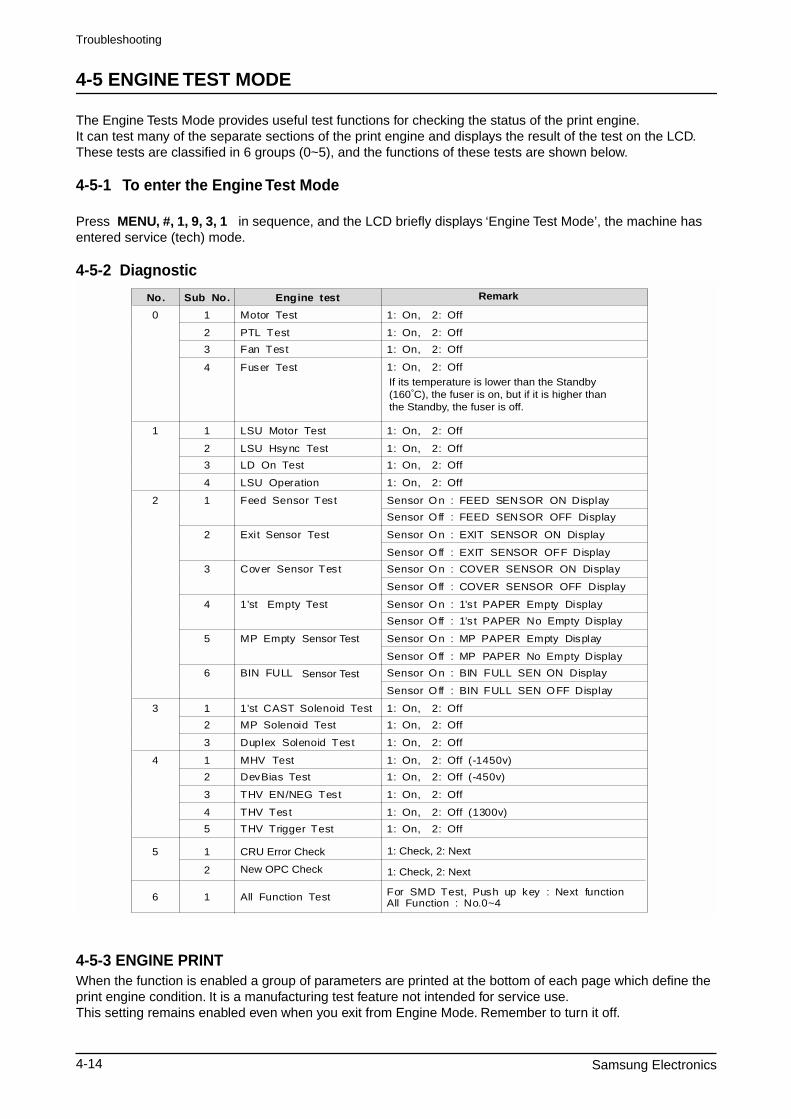
4-5 ENGINE TEST MODE
The Engine Tests Mode provides useful test functions for checking the status of the print engine.It can test many of the separate sections of the print engine and displays the result of the test on the LCD. These tests are classified in 6 groups (0~5), and the functions of these tests are shown below.
4-5-1 To enter the Engine Test Mode
Press MENU, #, 1, 9, 3, 1 in sequence, and the LCD briefly displays ‘Engine Test Mode’, the machine has entered service (tech) mode.
4-5-2 Diagnostic
4-5-3 ENGINE PRINTWhen the function is enabled a group of parameters are printed at the bottom of each page which define the print engine condition. It is a manufacturing test feature not intended for service use.This setting remains enabled even when you exit from Engine Mode. Remember to turn it off.
No. Sub No. Engine test
0 1 Motor Test 1: On, 2: Off
2 PTL Test 1: On, 2: Off
3 Fan Test 1: On, 2: Off
4 Fuser Test 1If its temperature is lower than the Standby (160 C), the fuser is on, but if it is higher than the Standby, the fuser is off.
: On, 2: Off
1 1 LSU Motor Test 1: On, 2: Off
2 LSU Hsync Test 1: On, 2: Off
3 LD On Test 1: On, 2: Off
4 LSU Operation 1: On, 2: Off
2 1 Feed Sensor Test Sensor On : FEED SENSOR ON Display
Sensor Off : FEED SENSOR OFF Display
2 Exit Sensor Test Sensor On : EXIT SENSOR ON Display
Sensor Off : EXIT SENSOR OFF Display
3 Cover Sensor Test Sensor On : COVER SENSOR ON Display
Sensor Off : COVER SENSOR OFF Display
4 1’st Empty Test Sensor On : 1’st PAPER Empty Display
Sensor Off : 1’st PAPER No Empty Display
5 MP Empty Sensor Test
Sensor Test
Sensor On : MP PAPER Empty Display
Sensor Off : MP PAPER No Empty Display
6 BIN FULL Sensor On : BIN FULL SEN ON Display
Sensor Off : BIN FULL SEN OFF Display
3 1 1’st CAST Solenoid Test 1: On, 2: Off
2 MP Solenoid Test 1: On, 2: Off
3 Duplex Solenoid Test 1: On, 2: Off
4 1 MHV Test 1: On, 2: Off (-1450v)
2 DevBias Test 1: On, 2: Off (-450v)
3 THV EN/NEG Test 1: On, 2: Off
4 THV Test 1: On, 2: Off (1300v)
5 THV Trigger Test 1: On, 2: Off
5 1 CRU Error Check
1: Check, 2: Next
1: Check, 2: Next
6 1 All Function Test For SMD Test, Push up key : Next functionAll Function : No.0~4
2 New OPC Check
Remark
Troubleshooting
Samsung Electronics 4-15
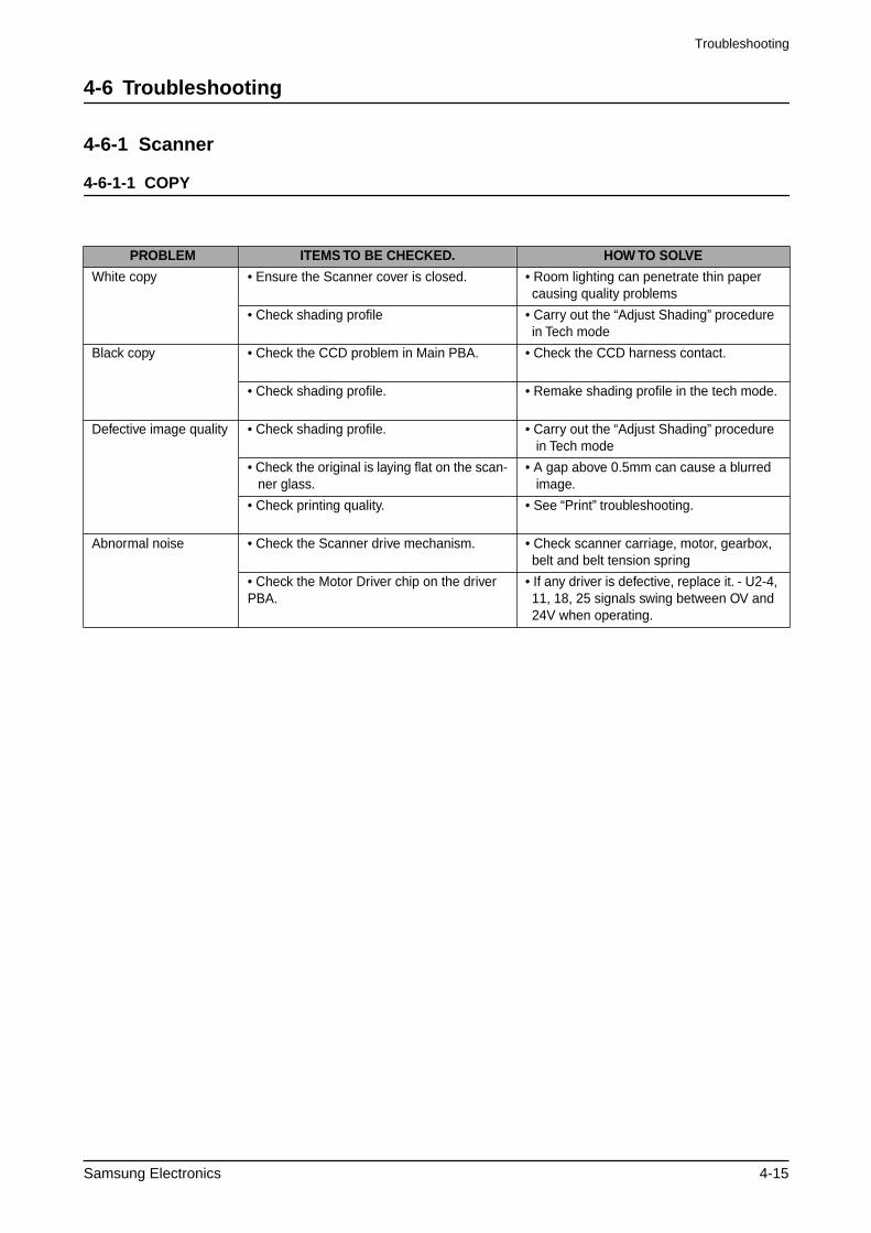
4-6 Troubleshooting
4-6-1 Scanner
4-6-1-1 COPY
PROBLEM ITEMS TO BE CHECKED. HOW TO SOLVE
White copy • Ensure the Scanner cover is closed. • Room lighting can penetrate thin paper causing quality problems
• Check shading profile • Carry out the “Adjust Shading” procedure in Tech mode
Black copy • Check the CCD problem in Main PBA. • Check the CCD harness contact.
• Check shading profile. • Remake shading profile in the tech mode.
Defective image quality • Check shading profile. • Carry out the “Adjust Shading” procedure in Tech mode
• Check the original is laying flat on the scan-ner glass.
• A gap above 0.5mm can cause a blurred image.
• Check printing quality. • See “Print” troubleshooting.
Abnormal noise • Check the Scanner drive mechanism. • Check scanner carriage, motor, gearbox, belt and belt tension spring
• Check the Motor Driver chip on the driver PBA.
• If any driver is defective, replace it. - U2-4, 11, 18, 25 signals swing between OV and 24V when operating.
Troubleshooting
4-16 Samsung Electronics
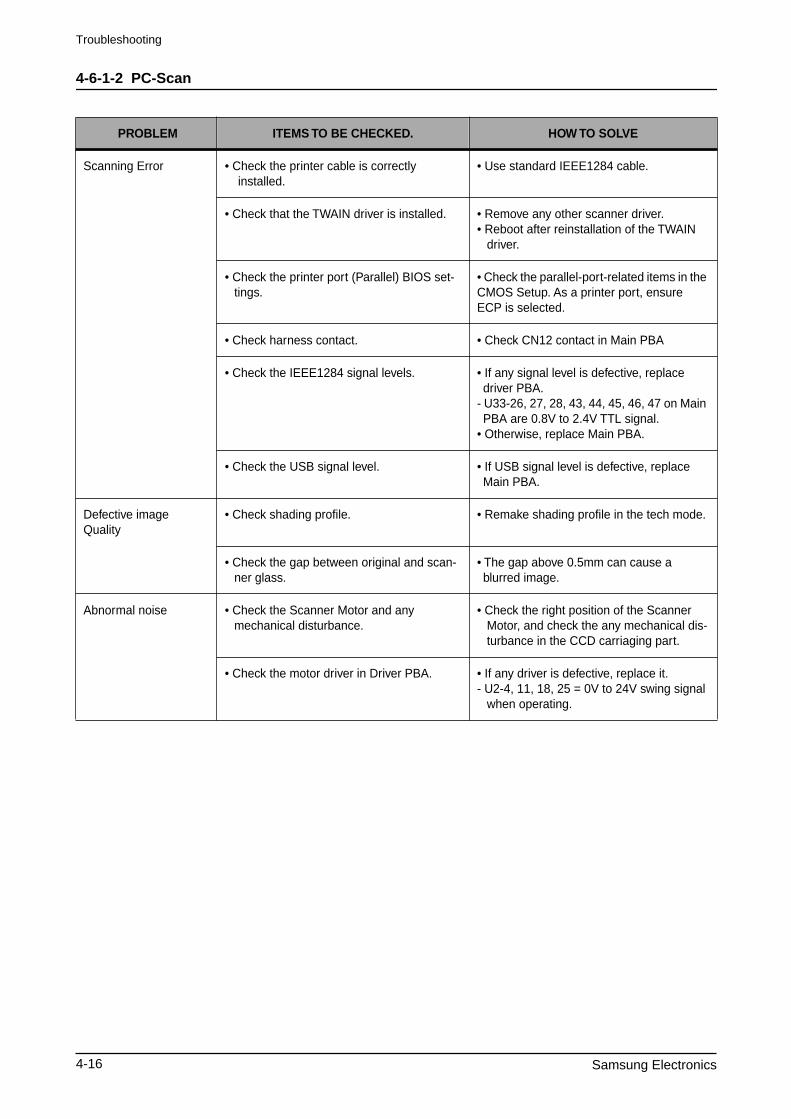
4-6-1-2 PC-Scan
PROBLEM ITEMS TO BE CHECKED. HOW TO SOLVE
Scanning Error • Check the printer cable is correctly installed.
• Use standard IEEE1284 cable.
• Check that the TWAIN driver is installed. • Remove any other scanner driver. • Reboot after reinstallation of the TWAIN
driver.
• Check the printer port (Parallel) BIOS set-tings.
• Check the parallel-port-related items in the CMOS Setup. As a printer port, ensure ECP is selected.
• Check harness contact. • Check CN12 contact in Main PBA
• Check the IEEE1284 signal levels. • If any signal level is defective, replace driver PBA.
- U33-26, 27, 28, 43, 44, 45, 46, 47 on Main PBA are 0.8V to 2.4V TTL signal.
• Otherwise, replace Main PBA.
• Check the USB signal level. • If USB signal level is defective, replace Main PBA.
Defective imageQuality
• Check shading profile. • Remake shading profile in the tech mode.
• Check the gap between original and scan-ner glass.
• The gap above 0.5mm can cause a blurred image.
Abnormal noise • Check the Scanner Motor and any mechanical disturbance.
• Check the right position of the Scanner Motor, and check the any mechanical dis-turbance in the CCD carriaging part.
• Check the motor driver in Driver PBA. • If any driver is defective, replace it. - U2-4, 11, 18, 25 = 0V to 24V swing signal
when operating.
Troubleshooting
Samsung Electronics 4-17
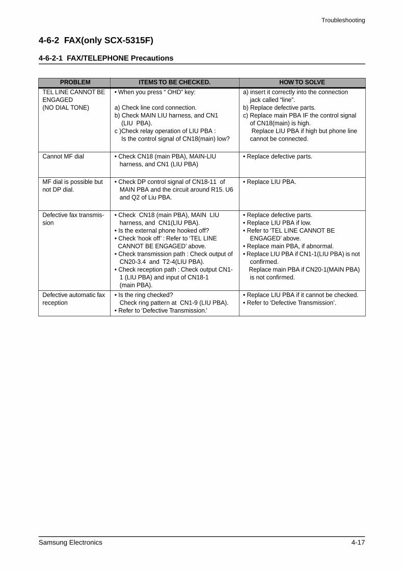
4-6-2 FAX(only SCX-5315F)
4-6-2-1 FAX/TELEPHONE Precautions
PROBLEM ITEMS TO BE CHECKED. HOW TO SOLVE
TEL LINE CANNOT BE ENGAGED (NO DIAL TONE)
• When you press “ OHD” key:
a) Check line cord connection.b) Check MAIN LIU harness, and CN1 (LIU PBA).c )Check relay operation of LIU PBA : Is the control signal of CN18(main) low?
a) insert it correctly into the connection jack called “line”.
b) Replace defective parts.c) Replace main PBA IF the control signal
of CN18(main) is high. Replace LIU PBA if high but phone line
cannot be connected.
Cannot MF dial • Check CN18 (main PBA), MAIN-LIU harness, and CN1 (LIU PBA)
• Replace defective parts.
MF dial is possible but not DP dial.
• Check DP control signal of CN18-11 of MAIN PBA and the circuit around R15. U6 and Q2 of Liu PBA.
• Replace LIU PBA.
Defective fax transmis-sion
• Check CN18 (main PBA), MAIN LIU harness, and CN1(LIU PBA).• Is the external phone hooked off?• Check ‘hook off’ : Refer to ‘TEL LINE CANNOT BE ENGAGED’ above.• Check transmission path : Check output of CN20-3.4 and T2-4(LIU PBA).• Check reception path : Check output CN1- 1 (LIU PBA) and input of CN18-1 (main PBA).
• Replace defective parts.• Replace LIU PBA if low.• Refer to ‘TEL LINE CANNOT BE
ENGAGED’ above.• Replace main PBA, if abnormal. • Replace LIU PBA if CN1-1(LIU PBA) is not
confirmed. Replace main PBA if CN20-1(MAIN PBA)
is not confirmed.
Defective automatic fax reception
• Is the ring checked? Check ring pattern at CN1-9 (LIU PBA).• Refer to ‘Defective Transmission.’
• Replace LIU PBA if it cannot be checked.• Refer to ‘Defective Transmission’.
Troubleshooting
4-18 Samsung Electronics
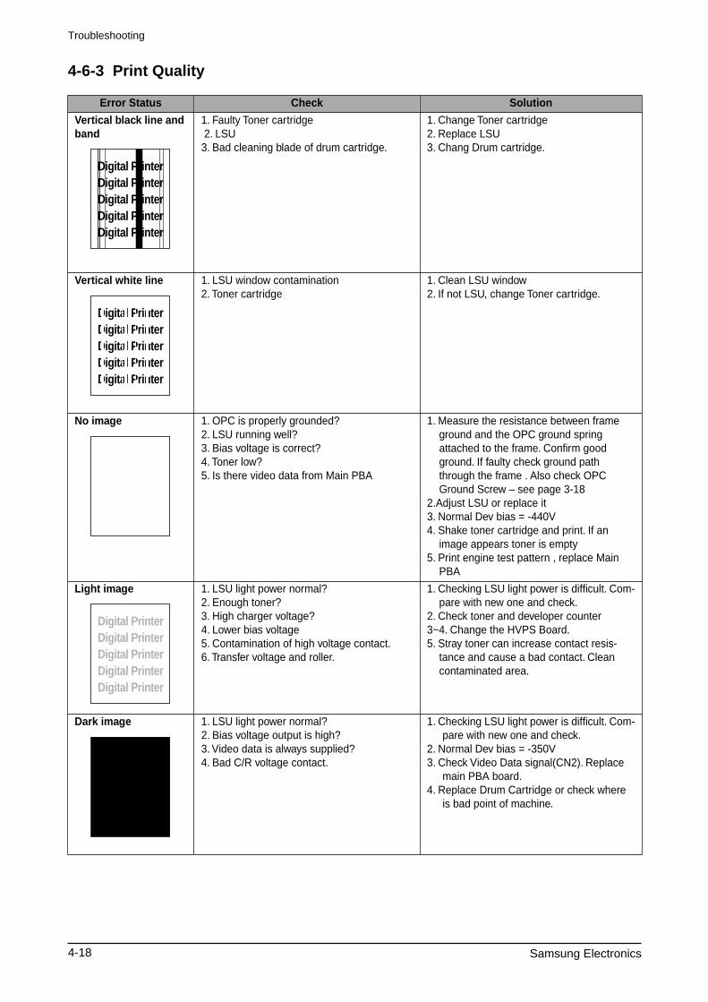
4-6-3 Print Quality
Error Status Check Solution
Vertical black line and band
1. Faulty Toner cartridge 2. LSU3. Bad cleaning blade of drum cartridge.
1. Change Toner cartridge2. Replace LSU3. Chang Drum cartridge.
Vertical white line 1. LSU window contamination2. Toner cartridge
1. Clean LSU window2. If not LSU, change Toner cartridge.
No image 1. OPC is properly grounded?2. LSU running well? 3. Bias voltage is correct? 4. Toner low? 5. Is there video data from Main PBA
1. Measure the resistance between frame ground and the OPC ground spring attached to the frame. Confirm good ground. If faulty check ground path through the frame . Also check OPC Ground Screw – see page 3-18
2.Adjust LSU or replace it3. Normal Dev bias = -440V4. Shake toner cartridge and print. If an
image appears toner is empty5. Print engine test pattern , replace Main
PBA
Light image 1. LSU light power normal? 2. Enough toner? 3. High charger voltage? 4. Lower bias voltage5. Contamination of high voltage contact. 6. Transfer voltage and roller.
1. Checking LSU light power is difficult. Com-pare with new one and check.
2. Check toner and developer counter3~4. Change the HVPS Board.5. Stray toner can increase contact resis-
tance and cause a bad contact. Clean contaminated area.
Dark image 1. LSU light power normal? 2. Bias voltage output is high? 3. Video data is always supplied?4. Bad C/R voltage contact.
1. Checking LSU light power is difficult. Com-pare with new one and check.
2. Normal Dev bias = -350V3. Check Video Data signal(CN2). Replace
main PBA board.4. Replace Drum Cartridge or check where
is bad point of machine.
Digital PrinterDigital PrinterDigital PrinterDigital PrinterDigital Printer
Digital PrinterDigital PrinterDigital PrinterDigital PrinterDigital Printer
Digital PrinterDigital PrinterDigital PrinterDigital PrinterDigital Printer
Digital PrinterDigital PrinterDigital PrinterDigital PrinterDigital Printer
Digital PrinterDigital Printer
Troubleshooting
Samsung Electronics 4-19
Background 1. High voltage output is normal? 2. C/R of Toner cartridge is contaminated?
1. Change the HVPS Board.2. Print a number of “Cleaning” sheets – if
problem persists change the cartridge..
Ghost 1. High voltage output. 2. Pre-Transfer Lamp. 3. Bad high voltage contact.
1. Change the HVPS Board.2. Check PTL lamp comes on –replace if
necessary3. Clean the inside machine or replace toner
cartridge.
Stains on back of paper
1. Contamination of transfer roller. 2. Toner debris in paper path 3. Pressure roller contamination
1. Clean the transfer roller with vacuum cleaner.
2. Clean the paper path with a cloth or air duster.
3. Remove fuser and replace it.
Poor Fusing 1. Paper quality and finish? 2. Check fusing temperature. 3. The machine was kept at a low tempera-
ture for a long time?
1. Should use recommended paper.2. Check engine controller board. If you do
not have a thermometer, measure the thermistor voltage to CPU, If 2.3V±5% when printing is correct therwise disas-semble fthe user and check the thermistor contacts and thermistor.
3. Re-check after allowing the machine to come up to room temperature.
Partial blank image (not periodic)
1. Toner is low?2. The toner cartridge is out of position?
1. Replace Toner cartridge.2. Checkand adjust.
Partial blank image(periodic)
1. repatative white or black marks at regular intervals.
Measure the spacing of the marks and com-pare the spacing to those given in the table below.
• Spacing 1 and 2 – Replace the OPC• Spacing 3 and 4 – replace the toner car
tridge• Spacing 5 – replace the transfer roller • Spacing 6 and 7 – replace the Fuser.
Error Status Check Solution
Digital PrinterDigital PrinterDigital PrinterDigital PrinterDigital Printer
Digital Printer
Digital Printer
Digital Printer
Digital Printer
Digital Printer
Digital Printer
Troubleshooting
4-20 Samsung Electronics
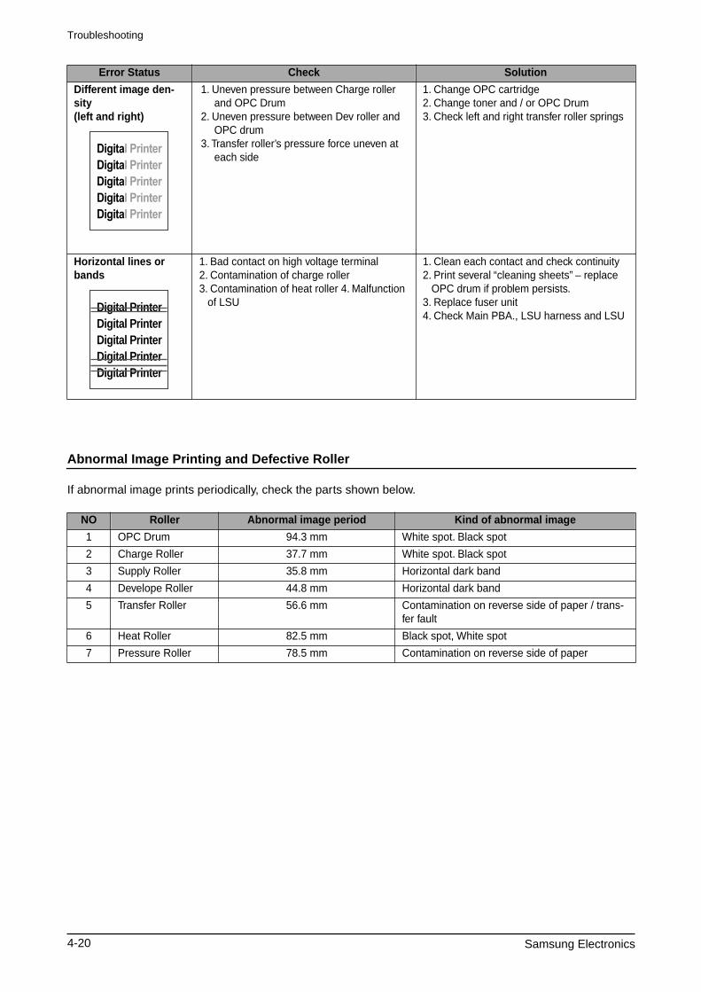
Abnormal Image Printing and Defective Roller
If abnormal image prints periodically, check the parts shown below.
Different image den-sity(left and right)
1. Uneven pressure between Charge roller and OPC Drum
2. Uneven pressure between Dev roller and OPC drum
3. Transfer roller’s pressure force uneven at each side
1. Change OPC cartridge2. Change toner and / or OPC Drum3. Check left and right transfer roller springs
Horizontal lines or bands
1. Bad contact on high voltage terminal 2. Contamination of charge roller3. Contamination of heat roller 4. Malfunction
of LSU
1. Clean each contact and check continuity2. Print several “cleaning sheets” – replace
OPC drum if problem persists.3. Replace fuser unit4. Check Main PBA., LSU harness and LSU
NO Roller Abnormal image period Kind of abnormal image
1 OPC Drum 94.3 mm White spot. Black spot
2 Charge Roller 37.7 mm White spot. Black spot
3 Supply Roller 35.8 mm Horizontal dark band
4 Develope Roller 44.8 mm Horizontal dark band
5 Transfer Roller 56.6 mm Contamination on reverse side of paper / trans-fer fault
6 Heat Roller 82.5 mm Black spot, White spot
7 Pressure Roller 78.5 mm Contamination on reverse side of paper
Error Status Check Solution
Digital PrinterDigital PrinterDigital PrinterDigital PrinterDigital Printer
Troubleshooting
Samsung Electronics 4-21
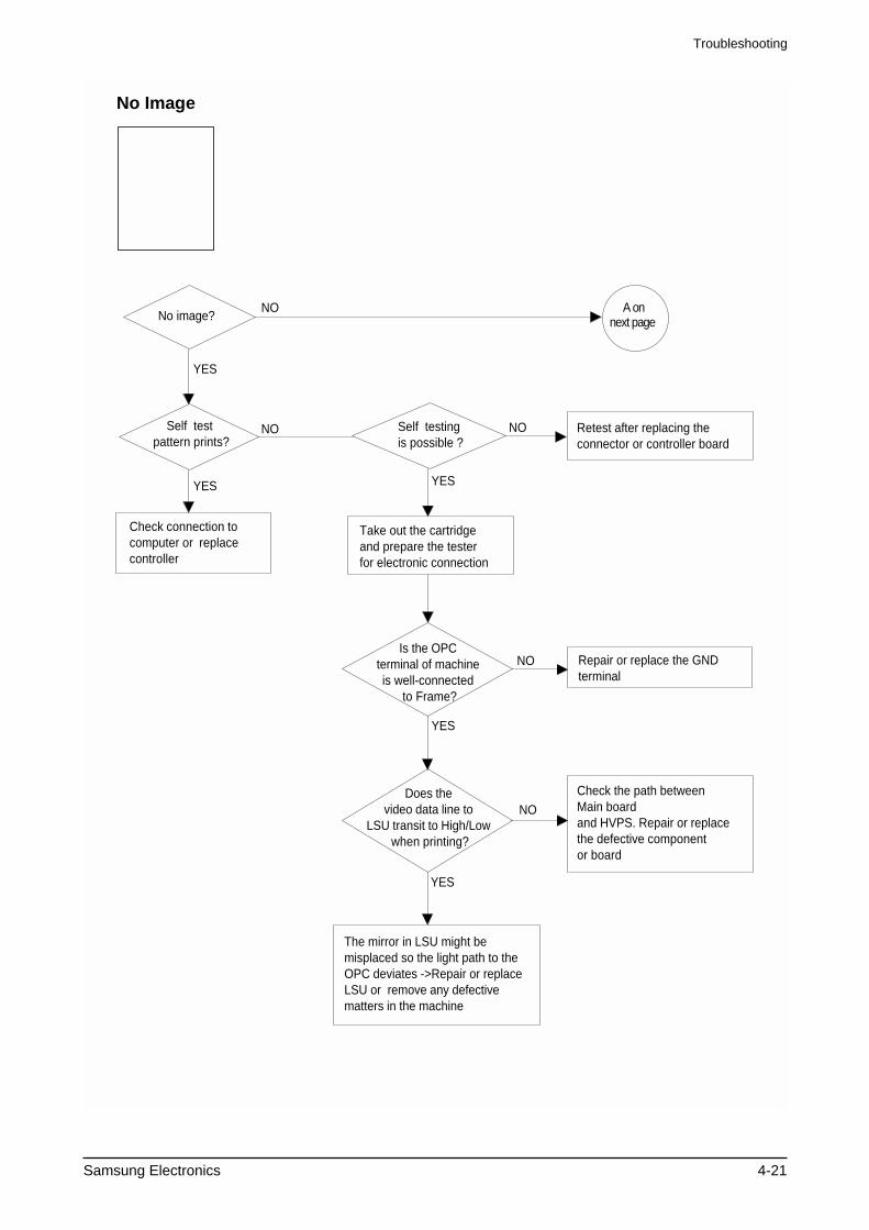
Check connection to computer or replace controller
Take out the cartridge and prepare the tester for electronic connection
Repair or replace the GND terminal
Check the path between Main board and HVPS. Repair or replace the defective component or board
The mirror in LSU might be misplaced so the light path to the OPC deviates ->Repair or replace LSU or remove any defective matters in the machine
Self test pattern prints?
No image?
Self testing is possible ?
Is the OPC terminal of machine is well-connected
to Frame?
Does the video data line to
LSU transit to High/Low when printing?
Retest after replacing the connector or controller board
A onnext page
NO
NO NO
NO
NO
YES
YES YES
YES
YES
No Image
Digital PrinterDigital PrinterDigital PrinterDigital PrinterDigital Printer
Troubleshooting
4-22 Samsung Electronics
Transfer roller might be out of its location -> Locate the roller into its place
This could occurs when he power of LSU is low or the density is low due to the obstacles on the window -> Replace LSU or clean the window
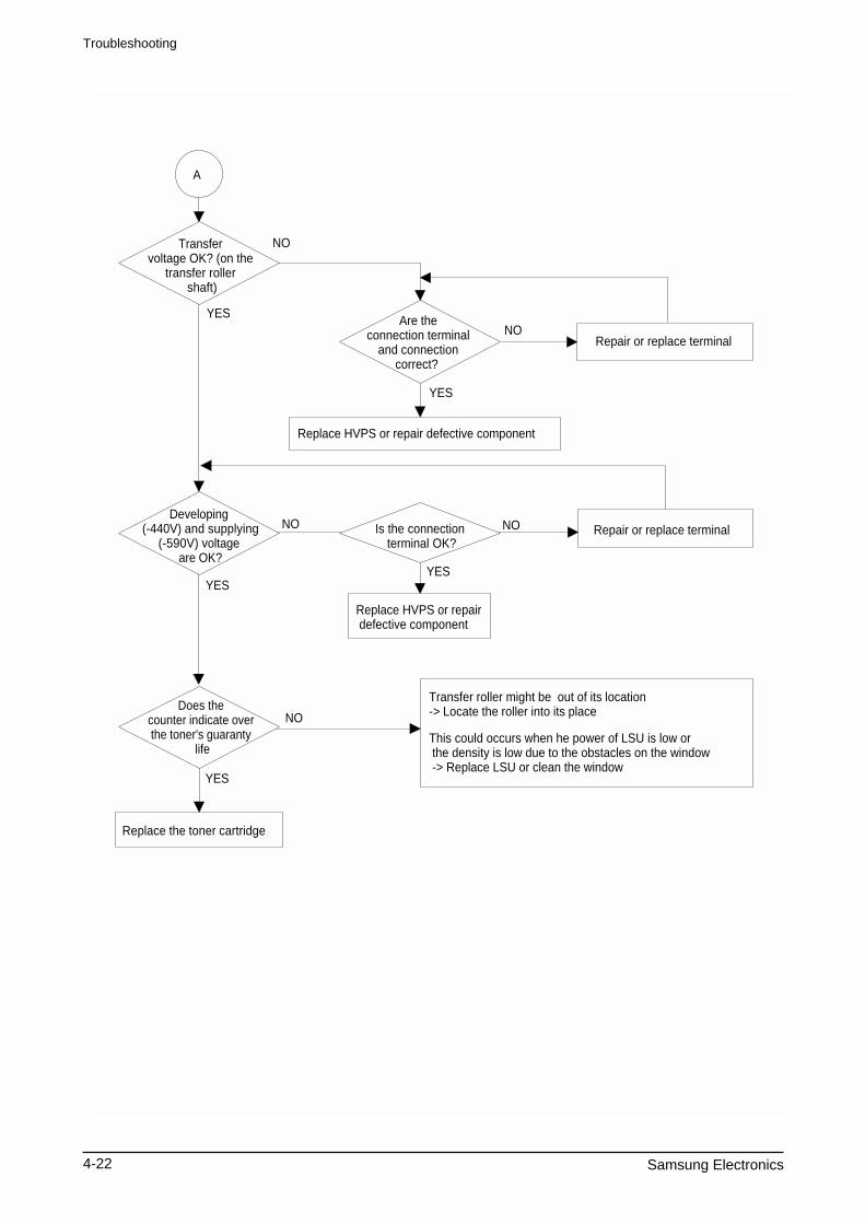
A
Transfer voltage OK? (on the
transfer roller shaft)
Are the connection terminal
and connection correct?
Repair or replace terminal
Replace HVPS or repair defective component
Is the connection terminal OK?
Replace HVPS or repair defective component
Repair or replace terminalDeveloping
(-440V) and supplying(-590V) voltage
are OK?
Does the counter indicate over the toner's guaranty
life
Replace the toner cartridge
NO
NO
NO NO
NO
YES
YES
YES
YES
YES
Troubleshooting
Samsung Electronics 4-23
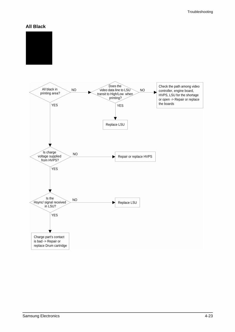
All black in printing area?
Is charge voltage supplied
from HVPS?
Is the Hsync/ signal received
in LSU?
Charge part's contact is bad -> Repair or replace Drum cartridge
Does the video data line to LSU
transit to High/Low when printing?
Replace LSU
Check the path among video controller, engine board, HVPS, LSU for the shortage or open -> Repair or replace the boards
Repair or replace HVPS
Replace LSU
NO
NO
NO
NO
YES
YES
YES
YES
All Black
Digital PrinterDigital PrinterDigital PrinterDigital PrinterDigital Printer
Troubleshooting
4-24 Samsung Electronics
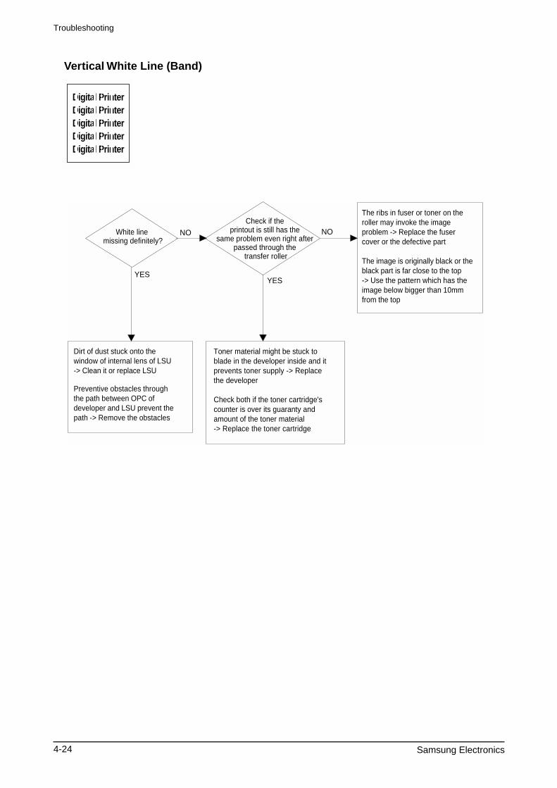
White line missing definitely?
Dirt of dust stuck onto the window of internal lens of LSU -> Clean it or replace LSU
Preventive obstacles through the path between OPC of developer and LSU prevent the path -> Remove the obstacles
Check if the printout is still has the
same problem even right after passed through the
transfer roller
Toner material might be stuck to blade in the developer inside and it prevents toner supply -> Replace the developer
Check both if the toner cartridge's counter is over its guaranty and amount of the toner material -> Replace the toner cartridge
The ribs in fuser or toner on the roller may invoke the image problem -> Replace the fuser cover or the defective part
The image is originally black or the black part is far close to the top-> Use the pattern which has the image below bigger than 10mm from the top
NO NO
YESYES
Vertical White Line (Band)
Digital PrinterDigital PrinterDigital PrinterDigital PrinterDigital Printer
Troubleshooting
Samsung Electronics 4-25
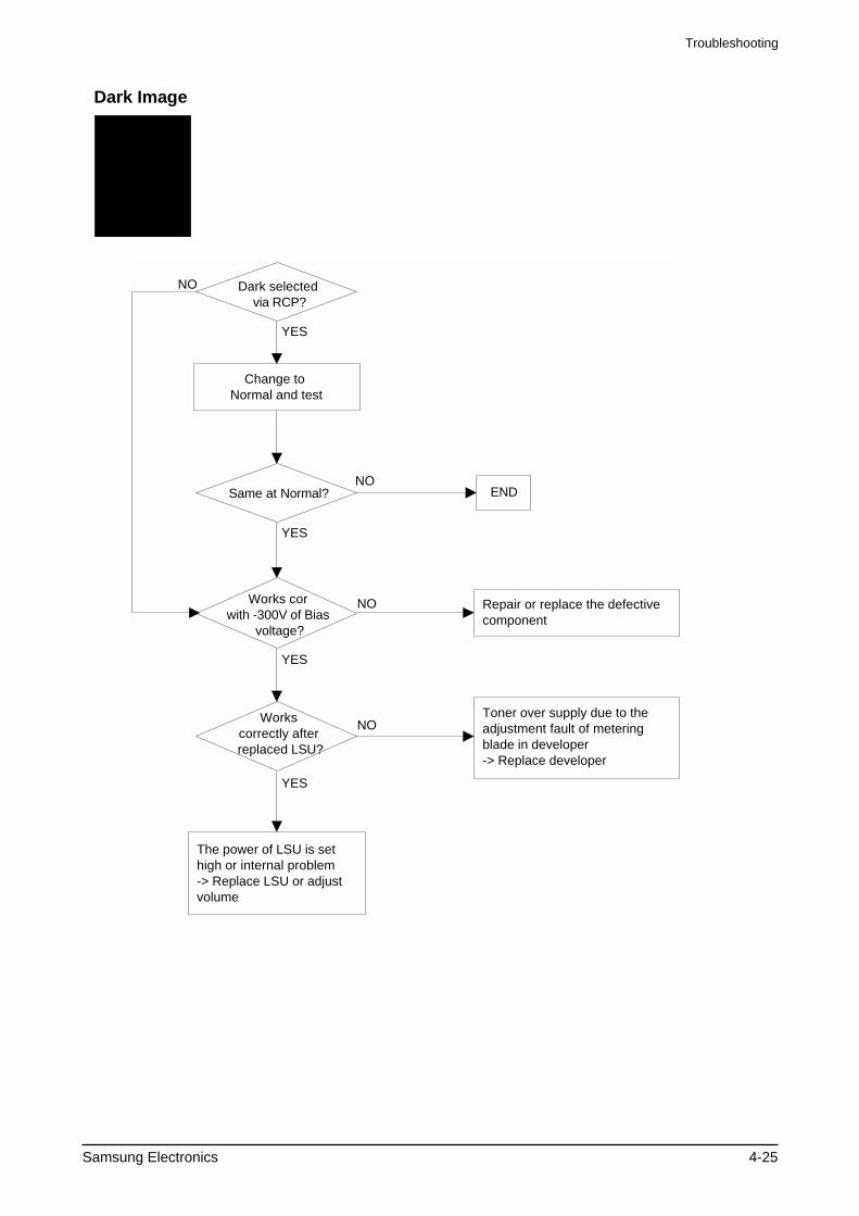
Dark selected via RCP?
Change to Normal and test
Works cor with -300V of Bias
voltage?
Works correctly after replaced LSU?
Repair or replace the defective component
The power of LSU is set high or internal problem -> Replace LSU or adjust volume
Same at Normal? END
NO
NO
NO
Toner over supply due to the adjustment fault of metering blade in developer -> Replace developer
NO
YES
YES
YES
YES
Dark Image
Digital PrinterDigital PrinterDigital PrinterDigital PrinterDigital Printer
Troubleshooting
4-26 Samsung Electronics
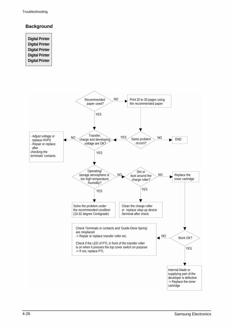
Recommended paper used?
Transfer, charge and developing
voltage are OK?
Operating/storage atmosphere is too high temperature
/humidity?
Solve the problem under the recommended condition (10-32 degree Centigrade)
Dirt or dust around the charge roller?
Clean the charge roller or replace step-up device/terminal after check
Work OK?
Internal blade or supplying part of the developer is defective-> Replace the toner cartridge
Check Terminals or contacts and 'Guide-Deve Spring' are misplaced-> Repair or replace transfer roller etc.
Check if the LED of PTL in front of the transfer roller is on when it presses the top cover switch on purpose -> If not, replace PTL
Print 20 to 30 pages using the recommended paper
Same problemoccurs?
- Adjust voltage or replace HVPS- Repair or replace after checking the terminals' contacts
END
Replace the toner cartridge
NO
NO
NO NO
NO
NO
YES
YES
YES
YES YES
YES
Background
Digital PrinterDigital PrinterDigital PrinterDigital PrinterDigital Printer
Troubleshooting
Samsung Electronics 4-27
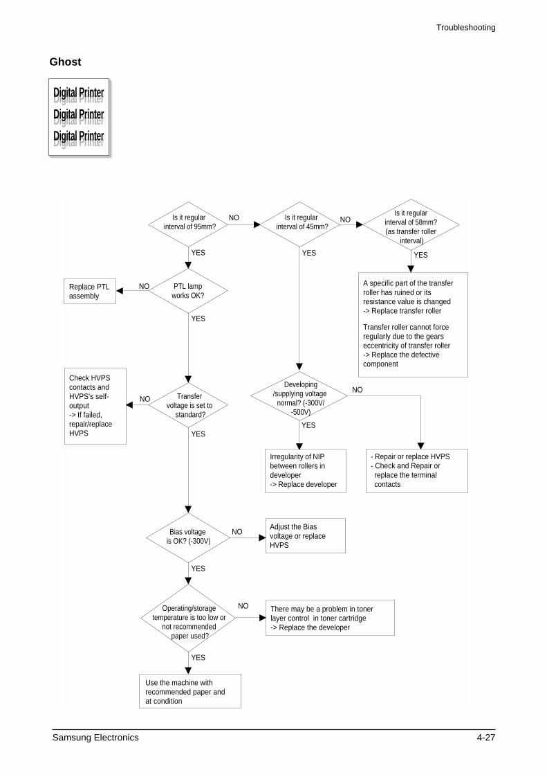
YES
Is it regular interval of 95mm?
PTL lamp works OK?
Transfer voltage is set to
standard?
Is it regular interval of 45mm?
Is it regular interval of 58mm? (as transfer roller
interval)
Developing/supplying voltage
normal? (-300V/-500V)
Check HVPS contacts and HVPS's self-output-> If failed, repair/replace HVPS
Replace PTLassembly
Irregularity of NIP between rollers in developer -> Replace developer
- Repair or replace HVPS - Check and Repair or replace the terminal contacts
A specific part of the transfer roller has ruined or its resistance value is changed -> Replace transfer roller
Transfer roller cannot force regularly due to the gears eccentricity of transfer roller-> Replace the defective component
Bias voltage is OK? (-300V)
Operating/storage temperature is too low or
not recommended paper used?
Adjust the Bias voltage or replace HVPS
There may be a problem in toner layer control in toner cartridge -> Replace the developer
Use the machine with recommended paper and at condition
NO
NO
NO
NO
NO
NO
NO
YES YESYES
YES
YESYES
YES
Ghost
Digital Printer
Digital Printer
Digital Printer
Digital Printer
Digital Printer
Digital Printer
Troubleshooting
4-28 Samsung Electronics
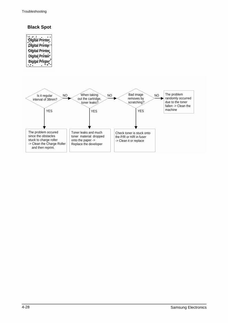
Black Spot
Is it regular interval of 38mm?
The problem occured since the obstacles stuck to charge roller-> Clean the Charge Roller and then reprint.
When taking out the cartridge,
toner leaks?
Toner leaks and much toner material dropped onto the paper -> Replace the developer
Bad image removes by scratching?
Check toner is stuck onto the P/R or H/R in fuser-> Clean it or replace
The problem randomly occurred due to the toner fallen -> Clean the machine
NO NO NO
YES YES YES
Digital PrinterDigital PrinterDigital PrinterDigital PrinterDigital Printer
Troubleshooting
Samsung Electronics 4-29
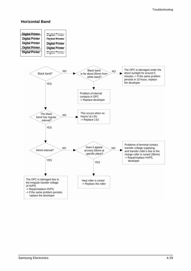
NOBlack band?
The black band has regular
interval?
Black band is far about 95mm from
white band?
Problem of internal contacts in OPC-> Replace developer
The OPC is damaged under the direct sunlight for around 5 minutes -> If the same problem persists in 10 hours, replace the developer
This occurs when no Hsync/ at LSU-> Replace LSU
94mm interval?
Heat roller is ruined -> Replace the roller
The OPC is damaged due to the irregular transfer voltage of HVPS -> Repair/replace HVPS-> If the same problem persists, replace the developer
Does it appear at every 83mm at
specific place?
Problems of terminal contact, transfer voltage supplying, and transfer roller's due to the charge roller is ruined (38mm)-> Repair/replace HVPS, developer
NO
NO NO
NO
YES
YES
YESYES
Horizontal Band
Digital PrinterDigital PrinterDigital PrinterDigital PrinterDigital Printer
Digital PrinterDigital PrinterDigital PrinterDigital PrinterDigital Printer
Troubleshooting
4-30 Samsung Electronics
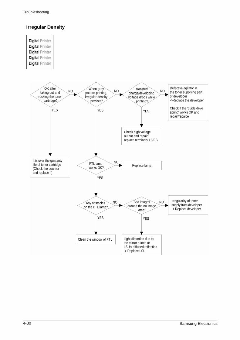
OK after taking out and
rocking the toner cartridge?
It is over the guaranty life of toner cartridge (Check the counter and replace it)
When gray pattern printing, irregular density
persists?
PTL lamp works OK?
Any obstacles on the PTL lamp?
transfer/charge/developing voltage drops while
printing?
Defective agitator in the toner supplying part of developer ->Replace the developer
Check if the 'guide deve spring' works OK and repair/repalce
Check high voltage output and repair/replace terminals, HVPS
Replace lamp
Clean the window of PTL
Bad images around the no image
area?
Irregularity of toner supply from developer-> Replace developer
Light distortion due to the mirror ruined or LSU's diffused reflection -> Replace LSU
NO NO NO
NO
NO NO
YES YES YES
YES
YES
YES
Irregular Density
Troubleshooting
Samsung Electronics 4-31
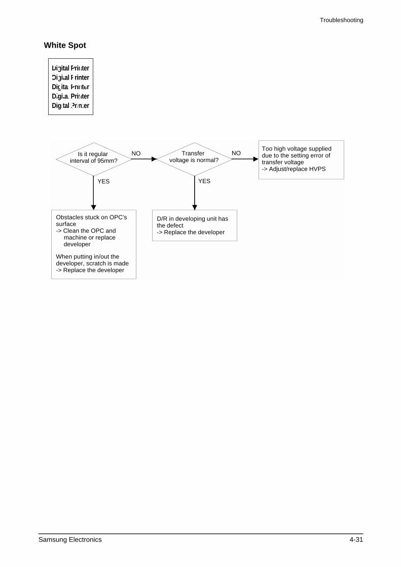
Is it regular interval of 95mm?
Obstacles stuck on OPC's surface -> Clean the OPC and machine or replace developer
When putting in/out the developer, scratch is made -> Replace the developer
Transfer voltage is normal?
D/R in developing unit has the defect -> Replace the developer
Too high voltage supplied due to the setting error of transfer voltage-> Adjust/replace HVPS
NO NO
YES YES
White Spot
Digital PrinterDigital PrinterDigital PrinterDigital PrinterDigital Printer
Troubleshooting
4-32 Samsung Electronics
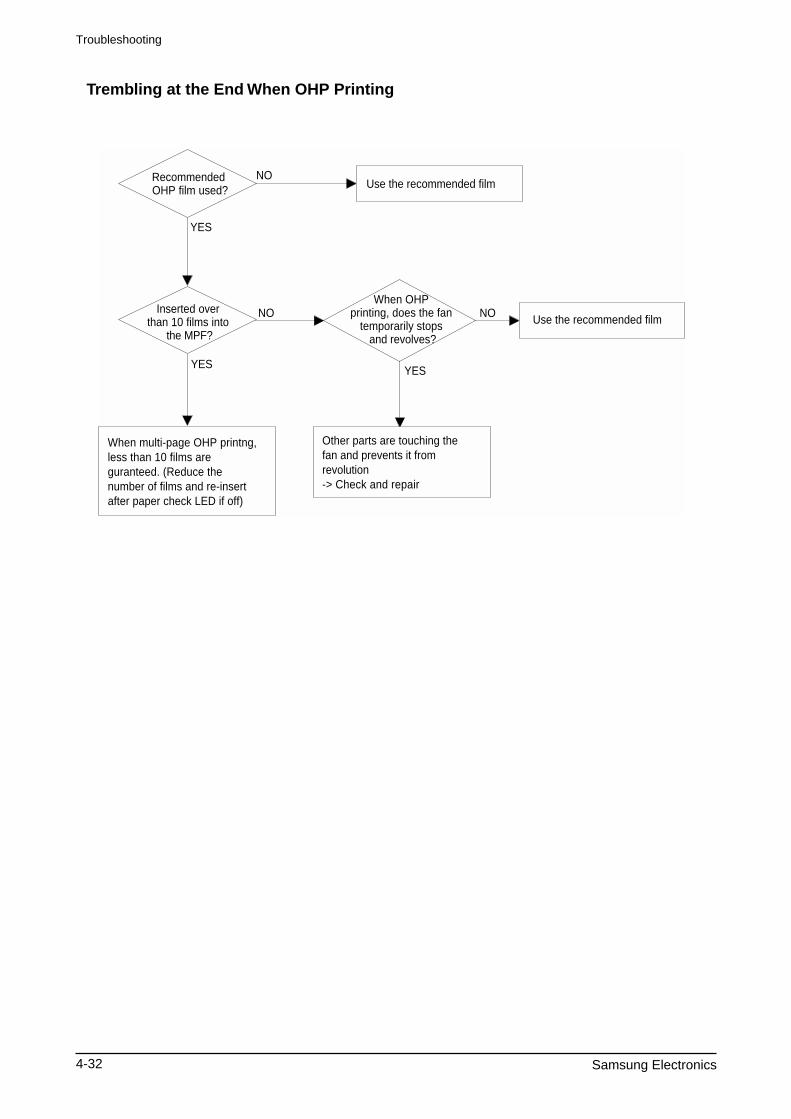
Recommended OHP film used?
Inserted over than 10 films into
the MPF?
When multi-page OHP printng, less than 10 films are guranteed. (Reduce the number of films and re-insert after paper check LED if off)
Use the recommended film
When OHP printing, does the fan
temporarily stops and revolves?
Use the recommended film
Other parts are touching the fan and prevents it from revolution-> Check and repair
NO
NO NO
YES
YES YES
Trembling at the End When OHP Printing
Troubleshooting
Samsung Electronics 4-33
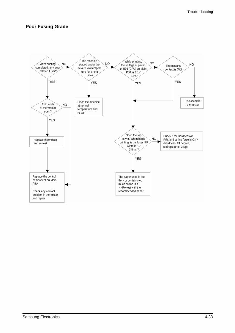
After printing completed, any error
related fuser?
Both ends of thermostat
open?
Replace thermostat and re-test
Replace the control component on MainPBA
Check any contact problem in thermistor and repair
The machine placed under the
severe low temperature for a long
time?
Place the machine at normal temperature and re-test
While printing, the voltage of pin 60
of U36 (CPU) on Main PBA is 2.1V
- 2.6V?
Thermistor's contact is OK?
Open the top cover. When black
printing, is the fuser NIP width is 3.0-
3.5mm?
The paper used is too thick or contains too much cotton in it -> Re-test with the recommended paper
Check if the hardness of P/R, and spring force is OK?(hardness: 24 degree, spring's force: 3 Kg)
Re-assemble thermistor
NO
NO
NO NO
NO
NO
YES
YES
YES
YES YES YES
Poor Fusing Grade
Troubleshooting
4-34 Samsung Electronics
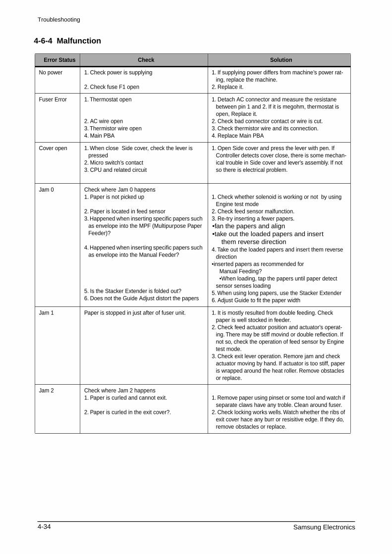
4-6-4 Malfunction
Error Status Check Solution
No power 1. Check power is supplying
2. Check fuse F1 open
1. If supplying power differs from machine’s power rat-ing, replace the machine.
2. Replace it.
Fuser Error 1. Thermostat open
2. AC wire open3. Thermistor wire open4. Main PBA
1. Detach AC connector and measure the resistane between pin 1 and 2. If it is megohm, thermostat is open, Replace it.
2. Check bad connector contact or wire is cut.3. Check thermistor wire and its connection.4. Replace Main PBA
Cover open 1. When close Side cover, check the lever is pressed
2. Micro switch’s contact3. CPU and related circuit
1. Open Side cover and press the lever with pen. If Controller detects cover close, there is some mechan-ical trouble in Side cover and lever’s assembly. If not so there is electrical problem.
Jam 0 Check where Jam 0 happens1. Paper is not picked up
2. Paper is located in feed sensor3. Happened when inserting specific papers such
as envelope into the MPF (Multipurpose Paper Feeder)?
4. Happened when inserting specific papers such as envelope into the Manual Feeder?
5. Is the Stacker Extender is folded out?6. Does not the Guide Adjust distort the papers
1. Check whether solenoid is working or not by using Engine test mode
2. Check feed sensor malfunction.3. Re-try inserting a fewer papers.
•fan the papers and align •take out the loaded papers and insert them reverse direction
4. Take out the loaded papers and insert them reverse direction
•inserted papers as recommended for Manual Feeding? •When loading, tap the papers until paper detect
sensor senses loading5. When using long papers, use the Stacker Extender6. Adjust Guide to fit the paper width
Jam 1 Paper is stopped in just after of fuser unit. 1. It is mostly resulted from double feeding. Check paper is well stocked in feeder.
2. Check feed actuator position and actuator’s operat-ing. There may be stiff movind or double reflection. If not so, check the operation of feed sensor by Engine test mode.
3. Check exit lever operation. Remore jam and check actuator moving by hand. If actuator is too stiff, paper is wrapped around the heat roller. Remove obstacles or replace.
Jam 2 Check where Jam 2 happens1. Paper is curled and cannot exit.
2. Paper is curled in the exit cover?.
1. Remove paper using pinset or some tool and watch if separate claws have any troble. Clean around fuser.
2. Check locking works wells. Watch whether the ribs of exit cover hace any burr or resisitive edge. If they do, remove obstacles or replace.
Troubleshooting
Samsung Electronics 4-35
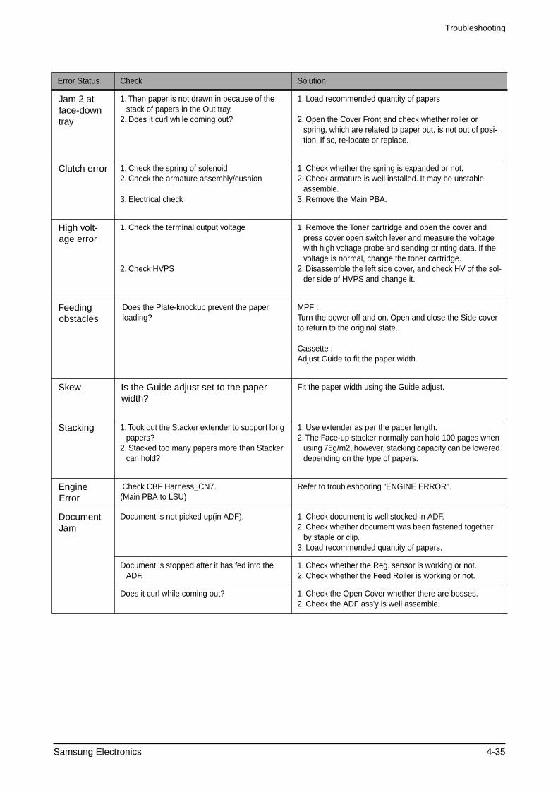
Error Status Check Solution
Jam 2 at face-down tray
1. Then paper is not drawn in because of the stack of papers in the Out tray.
2. Does it curl while coming out?
1. Load recommended quantity of papers
2. Open the Cover Front and check whether roller or spring, which are related to paper out, is not out of posi-tion. If so, re-locate or replace.
Clutch error
1. Check the spring of solenoid2. Check the armature assembly/cushion
3. Electrical check
1. Check whether the spring is expanded or not.2. Check armature is well installed. It may be unstable
assemble.3. Remove the Main PBA.
High volt-age error
1. Check the terminal output voltage
2. Check HVPS
1. Remove the Toner cartridge and open the cover and press cover open switch lever and measure the voltage with high voltage probe and sending printing data. If the voltage is normal, change the toner cartridge.
2. Disassemble the left side cover, and check HV of the sol-der side of HVPS and change it.
Feeding obstacles
Does the Plate-knockup prevent the paper loading?
MPF :Turn the power off and on. Open and close the Side cover to return to the original state.
Cassette :Adjust Guide to fit the paper width.
Skew Is the Guide adjust set to the paper width?
Fit the paper width using the Guide adjust.
Stacking
1. Took out the Stacker extender to support long papers?
2. Stacked too many papers more than Stacker can hold?
1. Use extender as per the paper length.2. The Face-up stacker normally can hold 100 pages when
using 75g/m2, however, stacking capacity can be lowered depending on the type of papers.
Engine Error
Check CBF Harness_CN7.(Main PBA to LSU)
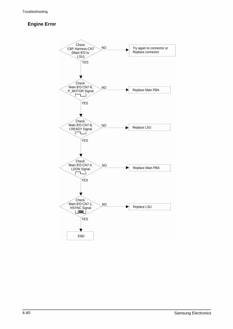
Refer to troubleshooring “ENGINE ERROR”.
Document Jam
Document is not picked up(in ADF). 1. Check document is well stocked in ADF.2. Check whether document was been fastened together
by staple or clip.3. Load recommended quantity of papers.
Document is stopped after it has fed into the ADF.
1. Check whether the Reg. sensor is working or not.2. Check whether the Feed Roller is working or not.
Does it curl while coming out? 1. Check the Open Cover whether there are bosses.2. Check the ADF ass'y is well assemble.
Troubleshooting
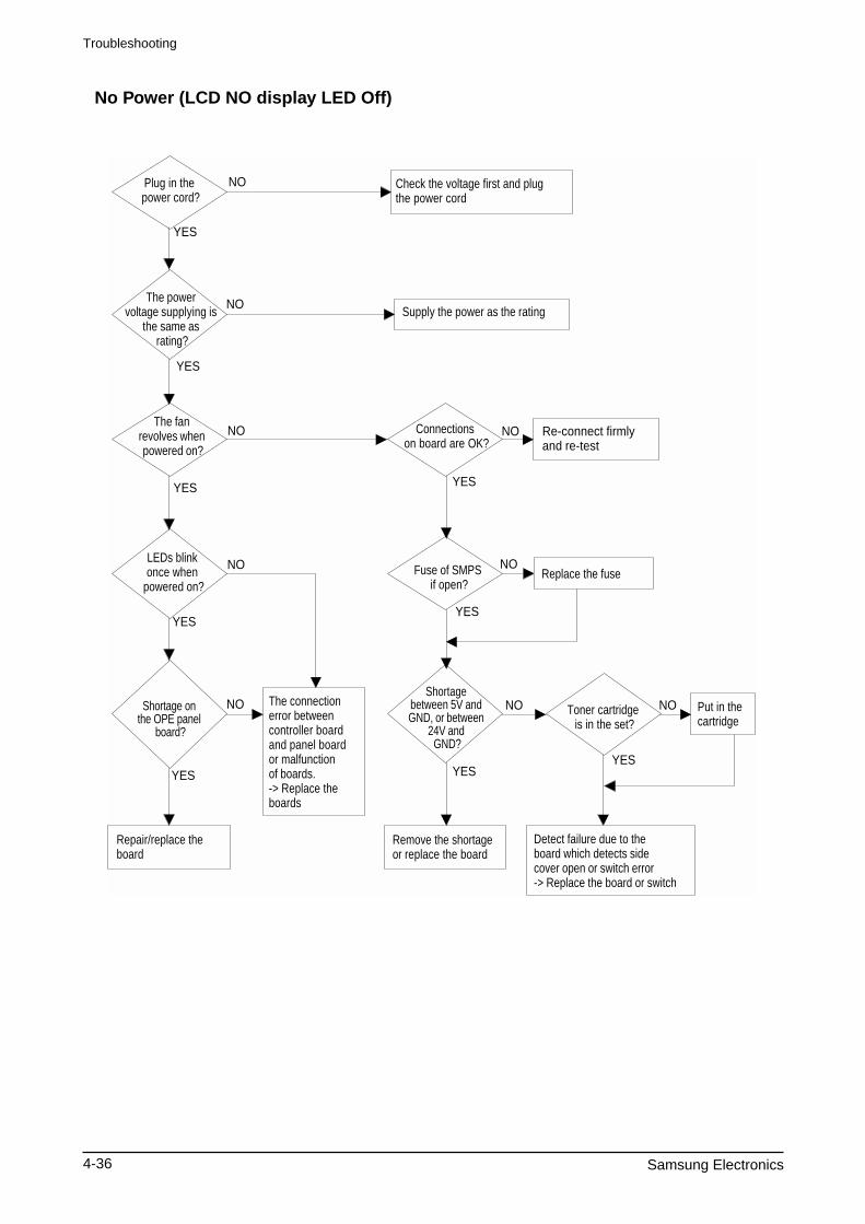
4-36 Samsung Electronics
Plug in the power cord?
The power voltage supplying is
the same as rating?
The fan revolves when powered on?
LEDs blink once when
powered on?
Shortage on the OPE panel
board?
Repair/replace the board
Check the voltage first and plug the power cord
Supply the power as the rating
Connections on board are OK?
Re-connect firmly and re-test
The connection error between controller board and panel board or malfunction of boards. -> Replace the boards
Fuse of SMPS if open?
Shortage between 5V and GND, or between
24V and GND?
Replace the fuse
Toner cartridge is in the set?
Detect failure due to the board which detects side cover open or switch error -> Replace the board or switch
Put in the cartridge
Remove the shortage or replace the board
NO
NO
NO
NO
NO
NO
NO NO
NO
YES
YES
YES YES
YES
YESYES
YES
YES
No Power (LCD NO display LED Off)
Troubleshooting
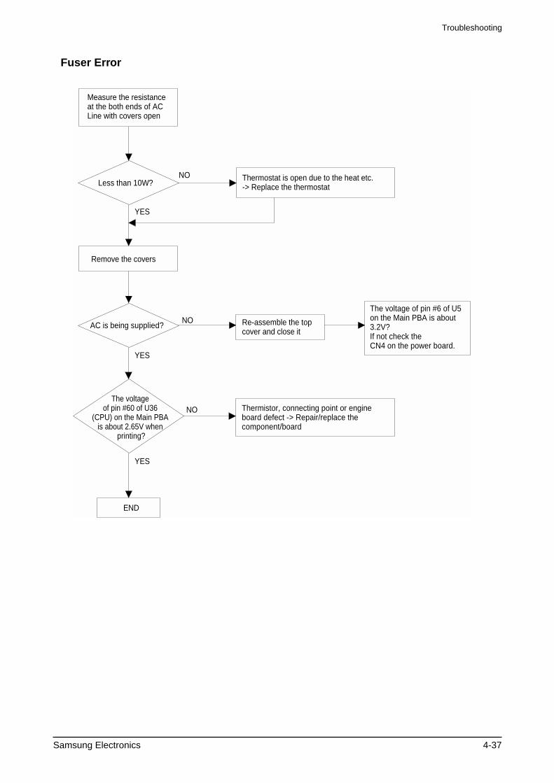
Samsung Electronics 4-37
Less than 10W?
AC is being supplied?
The voltage of pin #60 of U36
(CPU) on the Main PBA is about 2.65V when
printing?
END
Thermostat is open due to the heat etc.-> Replace the thermostat
The voltage of pin #6 of U5 on the Main PBA is about 3.2V?If not check the CN4 on the power board.
Measure the resistance at the both ends of AC Line with covers open
Remove the covers
Re-assemble the top cover and close it
Thermistor, connecting point or engine board defect -> Repair/replace the component/board
NO
NO
NO
YES
YES
YES
Fuser Error
Troubleshooting
4-38 Samsung Electronics
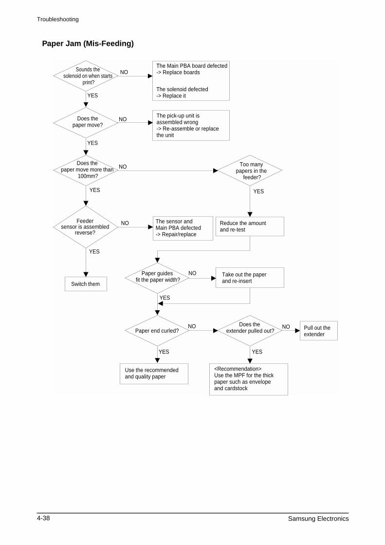
Sounds the solenoid on when starts
print?
Does the paper move?
Does the paper move more than
100mm?
The Main PBA board defected -> Replace boards
The solenoid defected -> Replace it
The pick-up unit is assembled wrong -> Re-assemble or replace the unit
Feeder sensor is assembled
reverse?
Switch them
The sensor and Main PBA defected -> Repair/replace
Too many papers in the
feeder?
Paper guides fit the paper width?
Paper end curled?Does the
extender pulled out?
<Recommendation>Use the MPF for the thick paper such as envelope and cardstock
Reduce the amount and re-test
Take out the paper and re-insert
Use the recommended and quality paper
Pull out the extender
NO
NO
NO
NO
NO
NO NO
YES
YES
YES
YES
YES
YES
YES YES
Paper Jam (Mis-Feeding)
Troubleshooting
Samsung Electronics 4-39
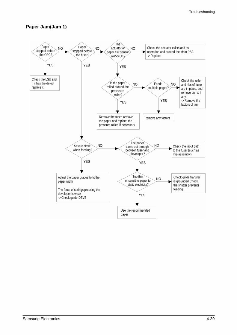
Paper stopped before
the OPC?
Check the LSU and if it has the defect replace it
Paper stopped before
the fuser?
Severe skew when feeding?
Adjust the paper guides to fit the paper width
The force of springs pressing the developer is weak -> Check guide-DEVE
The paper came out through between fuser and
developer?
Too thin or sensitive paper to
static electricity?
Use the recommended paper
Check guide transfer is grounded Check the shutter prevents feeding
Check the input path to the fuser (such as mis-assembly)
The actuator of
paper exit sensor works OK?
Check the actuator exists and its operation and around the Main PBA-> Replace
Is the paper rolled around the
presseure roller?
Remove the fuser, remove the paper and replace the pressure roller, if necessary
Feeds multiple pages?
Remove any factors
Check the roller and ribs of fuser are in place, and remove burrs, if any -> Remove the factors of jam
NO NO NO
NO
NO NO
NO
NO
YES YES YES
YES
YES YES
YES
YES
Paper Jam(Jam 1)
Troubleshooting
4-40 Samsung Electronics
Check CBF Harness-CN7
(Main B'D to LSU)
Check Main B'D CN7-9,P_MOTOR Signal
( )
Check Main B'D CN7-8,LREADY Signal
( )
END
Try again to connector orReplace connector
Replace Main PBA
Replace LSU
Replace Main PBA
Replace LSUNO
NO
NO
NO
NO
YES
YES
YES
YES
YES
Check Main B'D CN7-4,
LDON Signal( )
Check Main B'D CN7-1,HSYNC Signal
( )
Engine Error
Troubleshooting
Samsung Electronics 4-41
4-6-5 Toner Cartridge and Drum Cartridge Service
It is not guaranteed for the default caused by using other toner and Drum Cartridge cartridge other than the cartridge supplied by the Samsung Electronic or caused by non-licensed refill production.
Precautions on Safe-keeping of the Drum Cartridge
Excessive exposure to direct light more than a few minutes may cause damage to the cartridge.
Service for the Life of Toner Cartridge
If the printed image is light due to the life of the toner, you can temporarily improve the print quality by redis-tributing the toner(Shake the toner cartridge), however, you should replace the toner cartridge to solve the problem thoroughly.
Service for Judgement of Inferior Expendables and the Standard of Guarantee
Please refer to User's Manual or Instructions on Fax/Printer Expendables SVC for the judgement of inferior expendables and the standard of guarantee besides this service manual.
Troubleshooting
4-42 Samsung Electronics
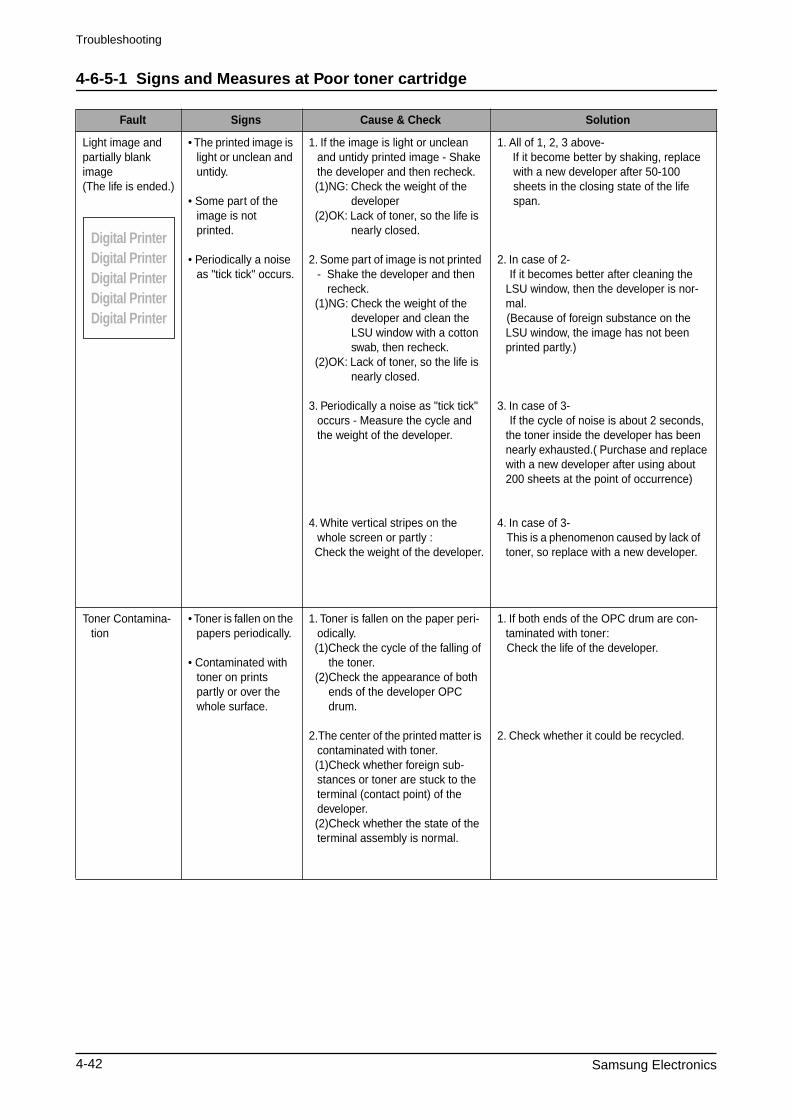
4-6-5-1 Signs and Measures at Poor toner cartridge
Fault Signs Cause & Check Solution
Light image and partially blank image(The life is ended.)
• The printed image is light or unclean and untidy.
• Some part of the image is not printed.
• Periodically a noise as "tick tick" occurs.
1. If the image is light or unclean and untidy printed image - Shake the developer and then recheck.
(1)NG: Check the weight of the developer
(2)OK: Lack of toner, so the life is nearly closed.
2. Some part of image is not printed - Shake the developer and then
recheck. (1)NG: Check the weight of the
developer and clean the LSU window with a cotton swab, then recheck.
(2)OK: Lack of toner, so the life is nearly closed.
3. Periodically a noise as "tick tick" occurs - Measure the cycle and the weight of the developer.
4. White vertical stripes on the whole screen or partly :
Check the weight of the developer.
1. All of 1, 2, 3 above- If it become better by shaking, replace
with a new developer after 50-100 sheets in the closing state of the life span.
2. In case of 2- If it becomes better after cleaning the
LSU window, then the developer is nor-mal.
(Because of foreign substance on the LSU window, the image has not been printed partly.)
3. In case of 3- If the cycle of noise is about 2 seconds,
the toner inside the developer has been nearly exhausted.( Purchase and replace with a new developer after using about 200 sheets at the point of occurrence)
4. In case of 3- This is a phenomenon caused by lack of
toner, so replace with a new developer.
Toner Contamina-tion
• Toner is fallen on the papers periodically.
• Contaminated with toner on prints partly or over the whole surface.
1. Toner is fallen on the paper peri-odically.
(1)Check the cycle of the falling of the toner.
(2)Check the appearance of both ends of the developer OPC drum.
2.The center of the printed matter is contaminated with toner.
(1)Check whether foreign sub-stances or toner are stuck to the terminal (contact point) of the developer.
(2)Check whether the state of the terminal assembly is normal.
1. If both ends of the OPC drum are con-taminated with toner:
Check the life of the developer.
2. Check whether it could be recycled.
Digital PrinterDigital PrinterDigital PrinterDigital PrinterDigital Printer
Troubleshooting
Samsung Electronics 4-43
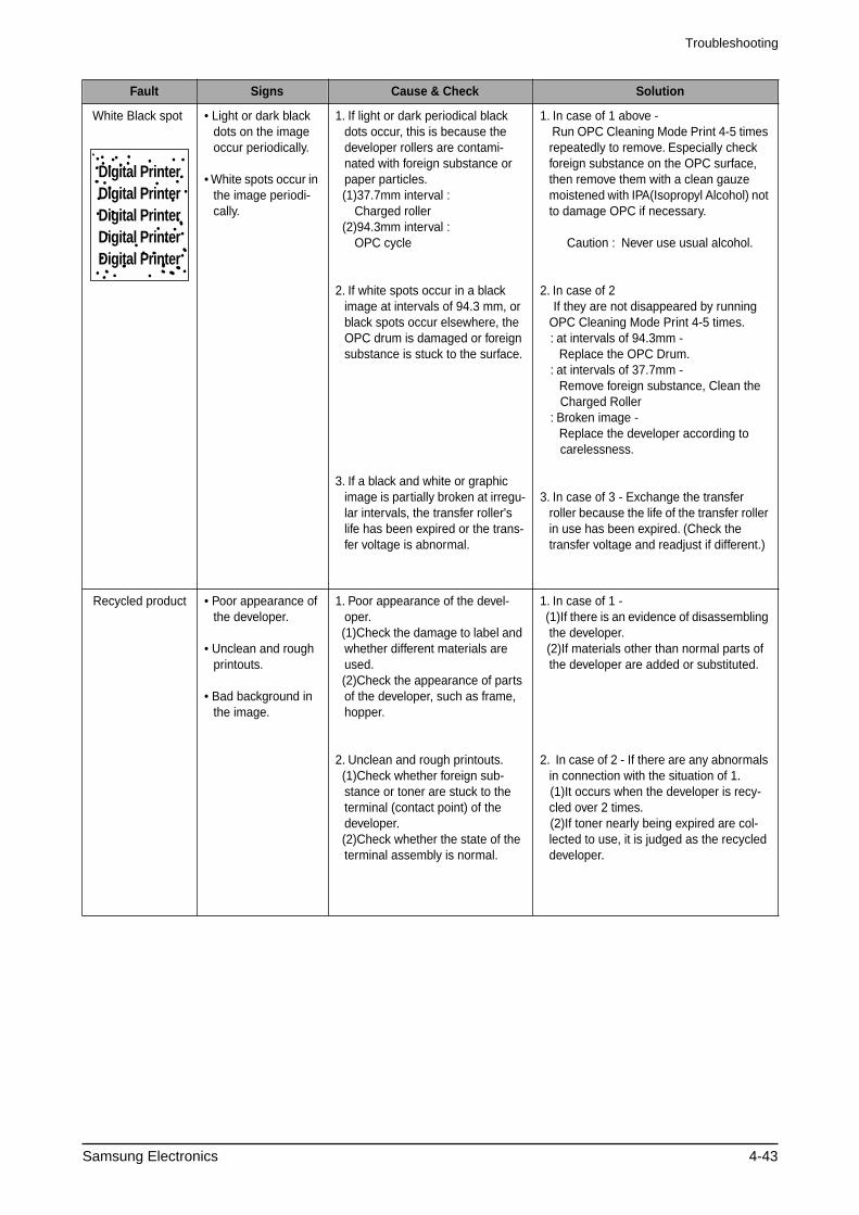
White Black spot • Light or dark black dots on the image occur periodically.
• White spots occur in the image periodi-cally.
1. If light or dark periodical black dots occur, this is because the developer rollers are contami-nated with foreign substance or paper particles.
(1)37.7mm interval : Charged roller
(2)94.3mm interval : OPC cycle
2. If white spots occur in a black image at intervals of 94.3 mm, or black spots occur elsewhere, the OPC drum is damaged or foreign substance is stuck to the surface.
3. If a black and white or graphic image is partially broken at irregu-lar intervals, the transfer roller's life has been expired or the trans-fer voltage is abnormal.
1. In case of 1 above - Run OPC Cleaning Mode Print 4-5 times
repeatedly to remove. Especially check foreign substance on the OPC surface, then remove them with a clean gauze moistened with IPA(Isopropyl Alcohol) not to damage OPC if necessary.
Caution : Never use usual alcohol.
2. In case of 2 If they are not disappeared by running
OPC Cleaning Mode Print 4-5 times. : at intervals of 94.3mm -
Replace the OPC Drum. : at intervals of 37.7mm -
Remove foreign substance, Clean the Charged Roller : Broken image -
Replace the developer according to carelessness.
3. In case of 3 - Exchange the transfer roller because the life of the transfer roller in use has been expired. (Check the transfer voltage and readjust if different.)
Recycled product • Poor appearance of the developer.
• Unclean and rough printouts.
• Bad background in the image.
1. Poor appearance of the devel-oper.
(1)Check the damage to label and whether different materials are used.
(2)Check the appearance of parts of the developer, such as frame, hopper.
2. Unclean and rough printouts. (1)Check whether foreign sub-
stance or toner are stuck to the terminal (contact point) of the developer.
(2)Check whether the state of the terminal assembly is normal.
1. In case of 1 - (1)If there is an evidence of disassembling
the developer. (2)If materials other than normal parts of
the developer are added or substituted.
2. In case of 2 - If there are any abnormals in connection with the situation of 1.
(1)It occurs when the developer is recy-cled over 2 times.
(2)If toner nearly being expired are col-lected to use, it is judged as the recycled developer.
Fault Signs Cause & Check Solution
Digital PrinterDigital PrinterDigital PrinterDigital PrinterDigital Printer
Troubleshooting
4-44 Samsung Electronics
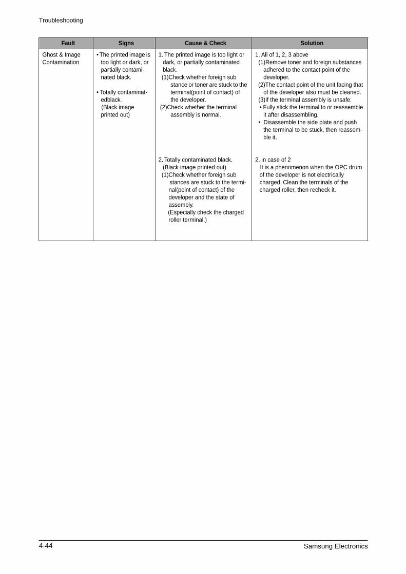
Ghost & Image Contamination
• The printed image is too light or dark, or partially contami-nated black.
• Totally contaminat-edblack.
(Black image printed out)
1. The printed image is too light or dark, or partially contaminated black.
(1)Check whether foreign sub stance or toner are stuck to the terminal(point of contact) of the developer.
(2)Check whether the terminal assembly is normal.
2. Totally contaminated black. (Black image printed out)
(1)Check whether foreign sub stances are stuck to the termi-
nal(point of contact) of the developer and the state of assembly.
(Especially check the charged roller terminal.)
1. All of 1, 2, 3 above (1)Remove toner and foreign substances
adhered to the contact point of the developer.
(2)The contact point of the unit facing that of the developer also must be cleaned.
(3)If the terminal assembly is unsafe: • Fully stick the terminal to or reassemble
it after disassembling. • Disassemble the side plate and push
the terminal to be stuck, then reassem-ble it.
2. In case of 2 It is a phenomenon when the OPC drum
of the developer is not electrically charged. Clean the terminals of the charged roller, then recheck it.
Fault Signs Cause & Check Solution
Troubleshooting
Samsung Electronics 4-45
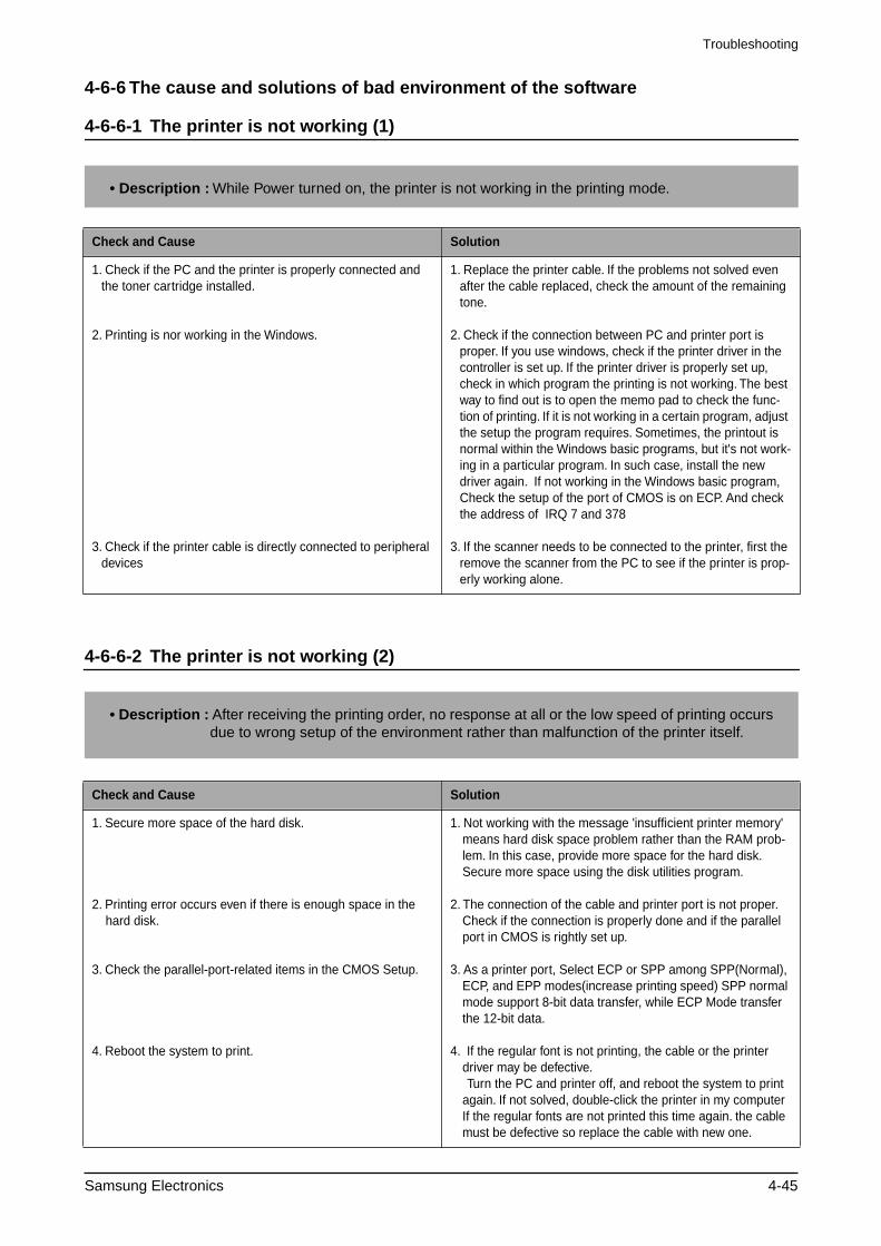
4-6-6 The cause and solutions of bad environment of the software
4-6-6-1 The printer is not working (1)
4-6-6-2 The printer is not working (2)
Check and Cause Solution
1. Check if the PC and the printer is properly connected and the toner cartridge installed.
2. Printing is nor working in the Windows.
3. Check if the printer cable is directly connected to peripheral devices
1. Replace the printer cable. If the problems not solved even after the cable replaced, check the amount of the remaining tone.
2. Check if the connection between PC and printer port is proper. If you use windows, check if the printer driver in the controller is set up. If the printer driver is properly set up, check in which program the printing is not working. The best way to find out is to open the memo pad to check the func-tion of printing. If it is not working in a certain program, adjust the setup the program requires. Sometimes, the printout is normal within the Windows basic programs, but it's not work-ing in a particular program. In such case, install the new driver again. If not working in the Windows basic program, Check the setup of the port of CMOS is on ECP. And check the address of IRQ 7 and 378
3. If the scanner needs to be connected to the printer, first the
remove the scanner from the PC to see if the printer is prop-erly working alone.
Check and Cause Solution
1. Secure more space of the hard disk.
2. Printing error occurs even if there is enough space in the hard disk.
3. Check the parallel-port-related items in the CMOS Setup.
4. Reboot the system to print.
1. Not working with the message 'insufficient printer memory' means hard disk space problem rather than the RAM prob-lem. In this case, provide more space for the hard disk. Secure more space using the disk utilities program.
2. The connection of the cable and printer port is not proper. Check if the connection is properly done and if the parallel port in CMOS is rightly set up.
3. As a printer port, Select ECP or SPP among SPP(Normal), ECP, and EPP modes(increase printing speed) SPP normal mode support 8-bit data transfer, while ECP Mode transfer the 12-bit data.
4. If the regular font is not printing, the cable or the printer driver may be defective.
Turn the PC and printer off, and reboot the system to print again. If not solved, double-click the printer in my computer If the regular fonts are not printed this time again. the cable must be defective so replace the cable with new one.
• Description : After receiving the printing order, no response at all or the low speed of printing occurs due to wrong setup of the environment rather than malfunction of the printer itself.
• Description :
While Power turned on, the printer is not working in the printing mode.
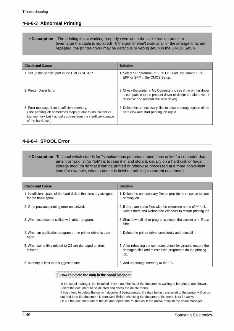
Troubleshooting
4-46 Samsung Electronics
4-6-6-3 Abnormal Printing
4-6-6-4 SPOOL Error
Check and Cause Solution
1. Set up the parallel port in the CMOS SETUP.
2. Printer Driver Error.
3. Error message from insufficient memory. (The printing job sometimes stops or due to insufficient vir-
tual memory, but it actually comes from the insufficient space of the hard disk.)
1. Select SPP(Normal) or ECP LPT Port the among ECP, EPP or SPP in the CMOS Setup.
2. Check the printer in My Computer.(to see if the printer driver is compatible to the present driver or delete the old driver, if defective and reinstall the new driver)
3. Delete the unnecessary files to secure enough space of the hard disk and start printing job again.
Check and Cause Solution
1. Insufficient space of the hard disk in the directory assigned for the basic spool.
2. If the previous printing error not solved.
3. When expected to collide with other program.
4. When an application program or the printer driver is dam-aged.
5. When some files related to OS are damaged or virus
infected.
6. Memory is less than suggested one.
1. Delete the unnecessary files to provide more space to start printing job.
2. If there are some files with the extension name of ****.jnl, Delete them and Reboot the Windows to restart printing job.
3. Shut down all other programs except the current one, if pos-sible.
4. Delete the printer driver completely and reinstall it.
5 After rebooting the computer, check for viruses, restore the damaged files and reinstall the program to do the printing job.
6. Add up enough memory to the PC.
• Description : The printing is not working properly even when the cable has no problem. (even after the cable is replaced) If the printer won't work at all or the strange fonts are repeated, the printer driver may be defective or wrong setup in the CMOS Setup.
• Description : To spool which stands for "simultaneous peripheral operations online" a computer doc-ument or task list (or "job") is to read it in and store it, usually on a hard disk or larger storage medium so that it can be printed or otherwise processed at a more convenient time (for example, when a printer is finished printing its current document).
How to delete the data in the spool manager.
In the spool manager, the installed drivers and the list of the documents waiting to be printed are shown. Select the document to be deleted and check the delete menu. If you intend to delete the current document being printed, the data being transferred to the printer will be put out and then the document is removed. Before choosing the document, the menu is still inactive. Or put the document out of the list and repeat the routine as in the above or finish the spool manager.
Exploded Views and Parts List
Samsung Electronics 5-1
5. Exploded View & Parts List
5-1. Main Exploded View & Parts List....................................... page(5-2)
5-2. Platen Ass’y Exploded View & Parts List
.................... page(5-5)
5-3. ADF ASS’Y Exploded View & Parts List
......................
page(5-9)5-4. Side Cover Ass’y Exploded View & Parts List
...........
page(5-12)5-5. Cassette Ass’y Exploded View & Parts List
...............
page(5-14)
5-6. Exit Ass’y Exploded View & Parts List................................ page(5-16)
5-7. Feeder Ass’y Exploded View & Parts List
..................
page(5-18)5-8. MP Ass’y Exploded View & Parts List
.........................
page(5-20)5-9. Base Frame Exploded View & Parts List
....................
page(5-22)5-10.Pick-up Ass’y Exploded View & Parts List
................
page(5-24)
5-11. Drive Ass’y Exploded View & Parts List........................... page(5-26)5-12. Main Frame Ass’y Exploded View & Parts List................. page(5-28)5-13. FuserAss’y Exploded View & Parts List........................... page(5-30)5-14. Screw.......................... page(5-32)
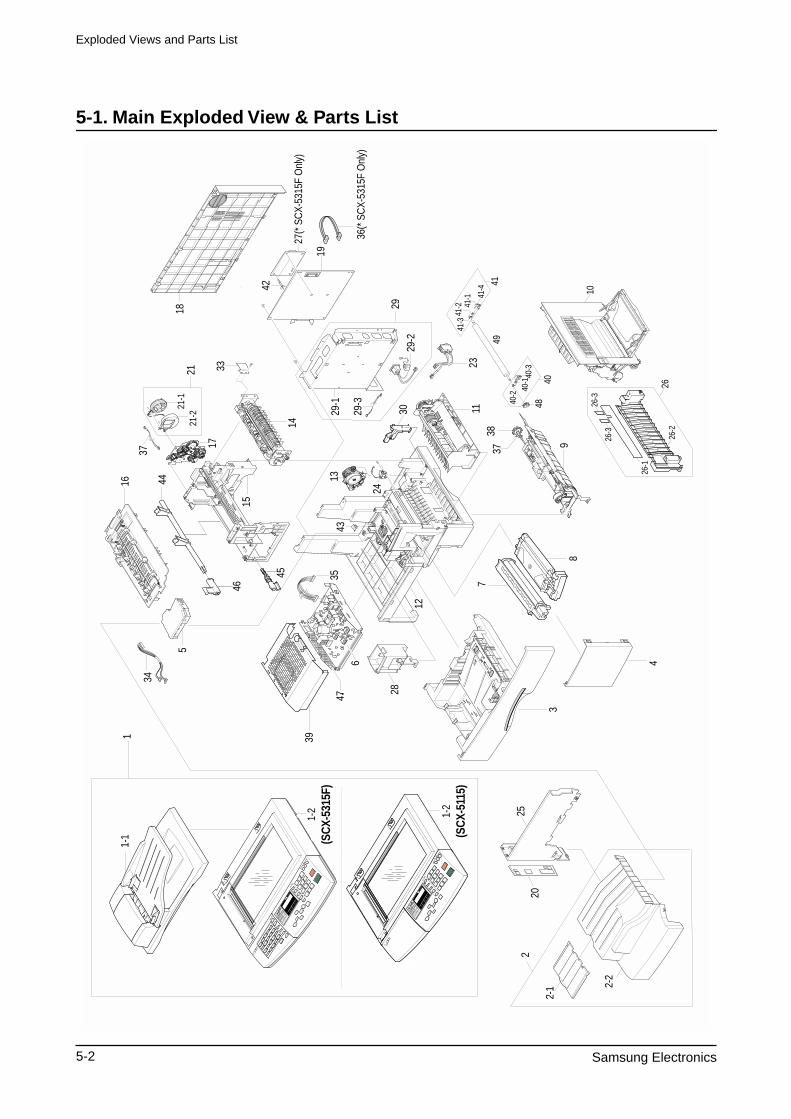
Exploded Views and Parts List
5-2 Samsung Electronics
5-1. Main Exploded View & Parts List
9
3837
1-2
(SC
X-53
15F)
1-2
(SC
X-51
15)
1-1
1
49
4840
41
41-1 41
-4
41-2
41-3
40-2
40-1
40-3
10
26-1
26-3
26-3
26-2
26
2025
28
2
2-1 2-
2
3
4
7
8
11
12
1343
6
35
5
34
16
15
45
46
44
17
21-2
21-1
21
37
14
33
19
36(*
SC
X-53
15F
Onl
y)
23
29-2
29-1
27(*
SC
X-53
15F
Onl
y)
24
3029-3
42
47
29
39
18
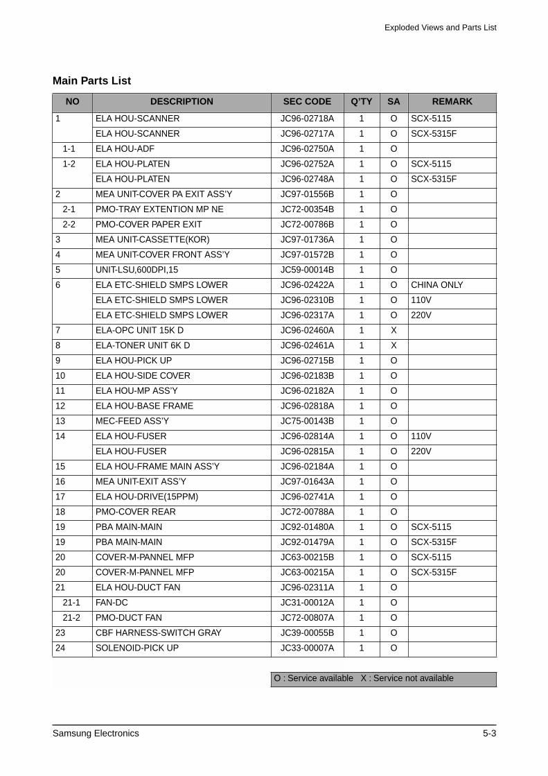
Exploded Views and Parts List
Samsung Electronics 5-3
Main Parts List
NO DESCRIPTION SEC CODE Q’TY SA REMARK
1 ELA HOU-SCANNER JC96-02718A 1 O SCX-5115
ELA HOU-SCANNER JC96-02717A 1 O SCX-5315F
1-1 ELA HOU-ADF JC96-02750A 1 O
1-2
ELA HOU-PLATEN JC96-02752A 1 O SCX-5115
ELA HOU-PLATEN JC96-02748A 1 O SCX-5315F
2 MEA UNIT-COVER PA EXIT ASS’Y JC97-01556B 1 O
2-1 PMO-TRAY EXTENTION MP NE JC72-00354B 1 O
2-2 PMO-COVER PAPER EXIT JC72-00786B 1 O
3 MEA UNIT-CASSETTE(KOR) JC97-01736A 1 O
4 MEA UNIT-COVER FRONT ASS’Y JC97-01572B 1 O
5 UNIT-LSU,600DPI,15 JC59-00014B 1 O
6 ELA ETC-SHIELD SMPS LOWER JC96-02422A 1 O CHINA ONLY
ELA ETC-SHIELD SMPS LOWER JC96-02310B 1 O 110V
ELA ETC-SHIELD SMPS LOWER JC96-02317A 1 O 220V
7 ELA-OPC UNIT 15K D JC96-02460A 1 X
8 ELA-TONER UNIT 6K D JC96-02461A 1 X
9 ELA HOU-PICK UP JC96-02715B 1 O
10 ELA HOU-SIDE COVER JC96-02183B 1 O
11 ELA HOU-MP ASS’Y JC96-02182A 1 O
12 ELA HOU-BASE FRAME JC96-02818A 1 O
13 MEC-FEED ASS’Y JC75-00143B 1 O
14 ELA HOU-FUSER JC96-02814A 1 O 110V
ELA HOU-FUSER JC96-02815A 1 O 220V
15 ELA HOU-FRAME MAIN ASS’Y JC96-02184A 1 O
16 MEA UNIT-EXIT ASS’Y JC97-01643A 1 O
17 ELA HOU-DRIVE(15PPM) JC96-02741A 1 O
18 PMO-COVER REAR JC72-00788A 1 O
19 PBA MAIN-MAIN JC92-01480A 1 O SCX-5115
19 PBA MAIN-MAIN JC92-01479A 1 O SCX-5315F
20 COVER-M-PANNEL MFP JC63-00215B 1 O SCX-5115
20 COVER-M-PANNEL MFP JC63-00215A 1 O SCX-5315F
21 ELA HOU-DUCT FAN JC96-02311A 1 O
21-1 FAN-DC JC31-00012A 1 O
21-2 PMO-DUCT FAN JC72-00807A 1 O
23 CBF HARNESS-SWITCH GRAY JC39-00055B 1 O
24 SOLENOID-PICK UP JC33-00007A 1 O
O : Service available X : Service not available
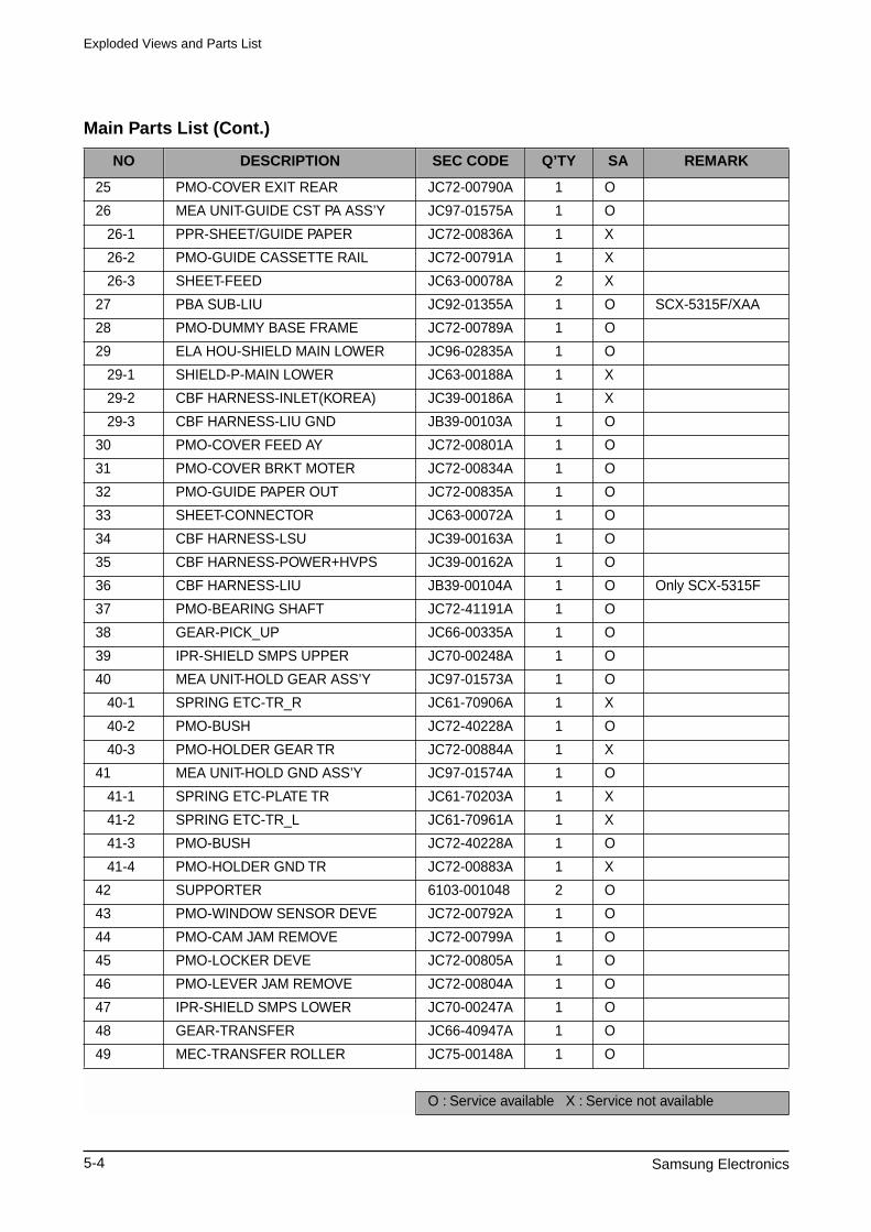
Exploded Views and Parts List
5-4 Samsung Electronics
Main Parts List (Cont.)
NO DESCRIPTION SEC CODE Q’TY SA REMARK
25 PMO-COVER EXIT REAR JC72-00790A 1 O
26 MEA UNIT-GUIDE CST PA ASS’Y JC97-01575A 1 O
26-1 PPR-SHEET/GUIDE PAPER JC72-00836A 1 X
26-2 PMO-GUIDE CASSETTE RAIL JC72-00791A 1 X
26-3 SHEET-FEED JC63-00078A 2 X
27 PBA SUB-LIU JC92-01355A 1 O SCX-5315F/XAA
28 PMO-DUMMY BASE FRAME JC72-00789A 1 O
29 ELA HOU-SHIELD MAIN LOWER JC96-02835A 1 O
29-1 SHIELD-P-MAIN LOWER JC63-00188A 1 X
29-2 CBF HARNESS-INLET(KOREA) JC39-00186A 1 X
29-3 CBF HARNESS-LIU GND JB39-00103A 1 O
30 PMO-COVER FEED AY JC72-00801A 1 O
31 PMO-COVER BRKT MOTER JC72-00834A 1 O
32 PMO-GUIDE PAPER OUT JC72-00835A 1 O
33 SHEET-CONNECTOR JC63-00072A 1 O
34 CBF HARNESS-LSU JC39-00163A 1 O
35 CBF HARNESS-POWER+HVPS JC39-00162A 1 O
36 CBF HARNESS-LIU JB39-00104A 1 O Only SCX-5315F
37 PMO-BEARING SHAFT JC72-41191A 1 O
38 GEAR-PICK_UP JC66-00335A 1 O
39 IPR-SHIELD SMPS UPPER JC70-00248A 1 O
40 MEA UNIT-HOLD GEAR ASS’Y JC97-01573A 1 O
40-1 SPRING ETC-TR_R JC61-70906A 1 X
40-2 PMO-BUSH JC72-40228A 1 O
40-3 PMO-HOLDER GEAR TR JC72-00884A 1 X
41 MEA UNIT-HOLD GND ASS’Y JC97-01574A 1 O
41-1 SPRING ETC-PLATE TR JC61-70203A 1 X
41-2 SPRING ETC-TR_L JC61-70961A 1 X
41-3 PMO-BUSH JC72-40228A 1 O
41-4 PMO-HOLDER GND TR JC72-00883A 1 X
42 SUPPORTER 6103-001048 2 O
43 PMO-WINDOW SENSOR DEVE JC72-00792A 1 O
44 PMO-CAM JAM REMOVE JC72-00799A 1 O
45 PMO-LOCKER DEVE JC72-00805A 1 O
46 PMO-LEVER JAM REMOVE JC72-00804A 1 O
47 IPR-SHIELD SMPS LOWER JC70-00247A 1 O
48 GEAR-TRANSFER JC66-40947A 1 O
49 MEC-TRANSFER ROLLER JC75-00148A 1 O
O : Service available X : Service not available
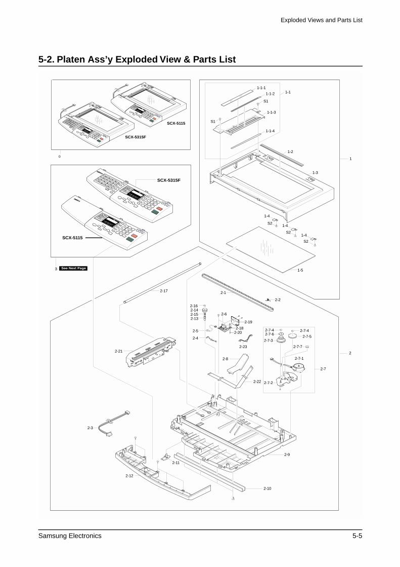
Exploded Views and Parts List
Samsung Electronics 5-5
5-2. Platen Ass’y Exploded View & Parts List
1-1-11-11-1-2
1-1-4
S1
S1
1-1-3
1-2
1-3
1-5
1-4
S2
S2
S2
1-4
1-4
2-17
2-2
2-21
2-22
2-1
2-9
2-11
2-10
2-12
2-16
2-13
2-5
2-4
2-18
2-19
2-142-15
2-20
2-6
2
1
2-7-42-7-4
2-7-5
2-7-7
2-7
2-7-3
2-7-1
2-23
2-7-6
2-7-2
2-8
2-3
3
0
SCX-5315F
SCX-5315F
SCX-5115
SCX-5115
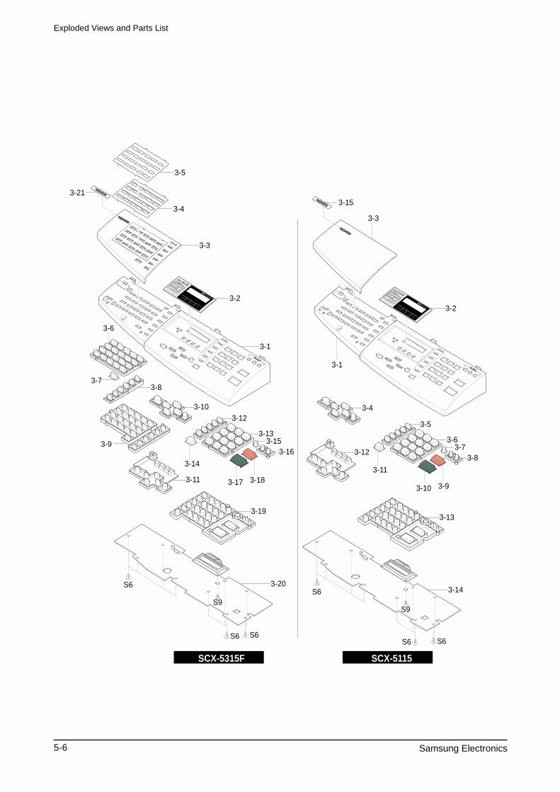
Exploded Views and Parts List
5-6 Samsung Electronics
3-1
3-2
3-3
3-4
3-21
3-5
3-6
3-73-8
3-9
3-10
3-11
3-12
3-13
3-14
3-153-16
3-17 3-18
3-19
3-20
3-1
3-2
3-3
3-4
3-12
3-5
3-6
3-11
3-73-8
3-10 3-9
3-13
3-14
SCX-5115SCX-5315F
3-15
S6
S6 S6
S9
S6S6
S6
S9
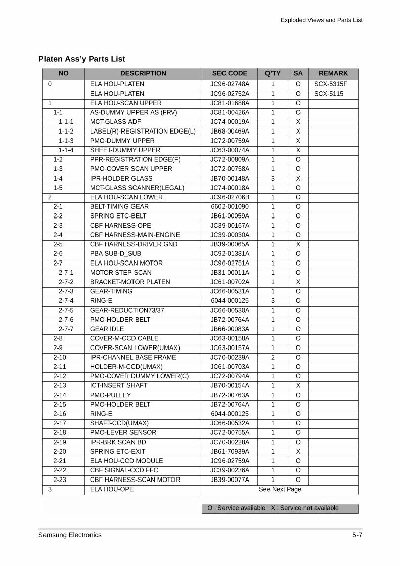
Exploded Views and Parts List
Samsung Electronics 5-7
Platen Ass’y Parts List
NO DESCRIPTION SEC CODE Q’TY SA REMARK
0 ELA HOU-PLATEN JC96-02748A 1 O SCX-5315FELA HOU-PLATEN JC96-02752A 1 O SCX-5115
1 ELA HOU-SCAN UPPER JC81-01688A 1 O 1-1 AS-DUMMY UPPER AS (FRV) JC81-00426A 1 O 1-1-1 MCT-GLASS ADF JC74-00019A 1 X 1-1-2 LABEL(R)-REGISTRATION EDGE(L) JB68-00469A 1 X 1-1-3 PMO-DUMMY UPPER JC72-00759A 1 X 1-1-4 SHEET-DUMMY UPPER JC63-00074A 1 X 1-2 PPR-REGISTRATION EDGE(F) JC72-00809A 1 O 1-3 PMO-COVER SCAN UPPER JC72-00758A 1 O 1-4 IPR-HOLDER GLASS JB70-00148A 3 X 1-5 MCT-GLASS SCANNER(LEGAL) JC74-00018A 1 O2 ELA HOU-SCAN LOWER JC96-02706B 1 O 2-1 BELT-TIMING GEAR 6602-001090 1 O 2-2 SPRING ETC-BELT JB61-00059A 1 O 2-3 CBF HARNESS-OPE JC39-00167A 1 O 2-4 CBF HARNESS-MAIN-ENGINE JC39-00030A 1 O 2-5 CBF HARNESS-DRIVER GND JB39-00065A 1 X 2-6 PBA SUB-D_SUB JC92-01381A 1 O 2-7 ELA HOU-SCAN MOTOR JC96-02751A 1 O 2-7-1 MOTOR STEP-SCAN JB31-00011A 1 O 2-7-2 BRACKET-MOTOR PLATEN JC61-00702A 1 X 2-7-3 GEAR-TIMING JC66-00531A 1 O 2-7-4 RING-E 6044-000125 3 O 2-7-5 GEAR-REDUCTION73/37 JC66-00530A 1 O 2-7-6 PMO-HOLDER BELT JB72-00764A 1 O 2-7-7 GEAR IDLE JB66-00083A 1 O 2-8 COVER-M-CCD CABLE JC63-00158A 1 O 2-9 COVER-SCAN LOWER(UMAX) JC63-00157A 1 O 2-10 IPR-CHANNEL BASE FRAME JC70-00239A 2 O 2-11 HOLDER-M-CCD(UMAX) JC61-00703A 1 O 2-12 PMO-COVER DUMMY LOWER(C) JC72-00794A 1 O 2-13 ICT-INSERT SHAFT JB70-00154A 1 X 2-14 PMO-PULLEY JB72-00763A 1 O 2-15 PMO-HOLDER BELT JB72-00764A 1 O 2-16 RING-E 6044-000125 1 O 2-17 SHAFT-CCD(UMAX) JC66-00532A 1 O 2-18 PMO-LEVER SENSOR JC72-00755A 1 O 2-19 IPR-BRK SCAN BD JC70-00228A 1 O 2-20 SPRING ETC-EXIT JB61-70939A 1 X 2-21 ELA HOU-CCD MODULE JC96-02759A 1 O 2-22 CBF SIGNAL-CCD FFC JC39-00236A 1 O 2-23 CBF HARNESS-SCAN MOTOR JB39-00077A 1 O3 ELA HOU-OPE See Next Page
O : Service available X : Service not available
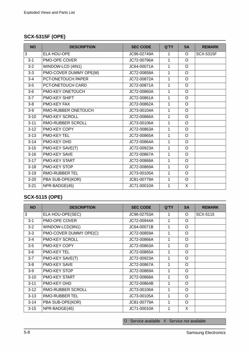
Exploded Views and Parts List
5-8 Samsung Electronics
SCX-5315F (OPE)
SCX-5115 (OPE)
NO DESCRIPTION SEC CODE Q’TY SA REMARK
3 ELA HOU-OPE JC96-02749A 1 O SCX-5315F
3-1 PMO-OPE COVER JC72-00796A 1 O
3-2 WINDOW-LCD (4IN1) JC64-00071A 1 O
3-3 PMO-COVER DUMMY OPE(M) JC72-00858A 1 O
3-4 PCT-ONETOUCH PAPER JC72-00872A 1 O
3-5 PCT-ONETOUCH CARD JC72-00871A 1 O
3-6 PMO-KEY ONETOUCH JC72-00860A 1 O
3-7 PMO-KEY SHIFT JC72-00861A 1 O
3-8 PMO-KEY FAX JC72-00862A 1 O
3-9 RMO-RUBBER ONETOUCH JC73-00104A 1 O
3-10 PMO-KEY SCROLL JC72-00866A 1 O
3-11 RMO-RUBBER SCROLL JC73-00106A 1 O
3-12 PMO-KEY COPY JC72-00863A 1 O
3-13 PMO-KEY TEL JC72-00865A 1 O
3-14 PMO-KEY OHD JC72-00864A 1 O
3-15 PMO-KEY SAVE(T) JC72-00923A 1 O
3-16 PMO-KEY SAVE JC72-00867A 1 O
3-17 PMO-KEY START JC72-00868A 1 O
3-18 PMO-KEY STOP JC72-00869A 1 O
3-19 RMO-RUBBER TEL JC73-00105A 1 O
3-20 PBA SUB-OPE(KOR) JC81-00779A 1 O
3-21 NPR-BADGE(45) JC71-00010A 1 X
NO DESCRIPTION SEC CODE Q’TY SA REMARK
3 ELA HOU-OPE(SEC) JC96-02753A 1 O SCX-5115
3-1 PMO-OPE COVER JC72-00944A 1 O
3-2 WINDOW-LCD(3IN1) JC64-00071B 1 O
3-3 PMO-COVER DUMMY OPE(C) JC72-00859A 1 O
3-4 PMO-KEY SCROLL JC72-00866A 1 O
3-5 PMO-KEY COPY JC72-00863A 1 O
3-6 PMO-KEY TEL JC72-00865A 1 O
3-7 PMO-KEY SAVE(T) JC72-00923A 1 O
3-8 PMO-KEY SAVE JC72-00867A 1 O
3-9 PMO-KEY STOP JC72-00869A 1 O
3-10 PMO-KEY START JC72-00868A 1 O
3-11 PMO-KEY OHD JC72-00864B 1 O
3-12 RMO-RUBBER SCROLL JC73-00106A 1 O
3-13 RMO-RUBBER TEL JC73-00105A 1 O
3-14 PBA SUB-OPE(KOR) JC81-00779A 1 O
3-15 NPR-BADGE(45) JC71-00010A 1 X
O : Service available X : Service not available
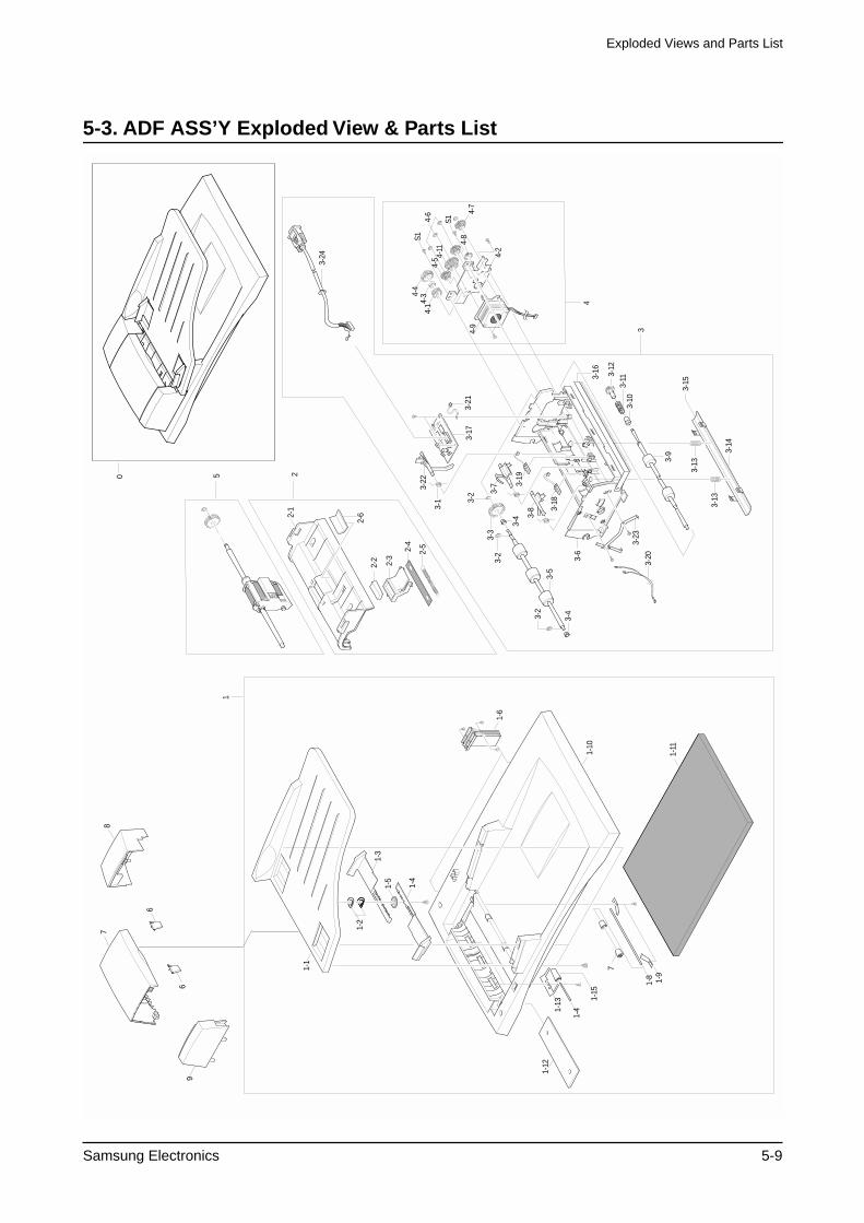
Exploded Views and Parts List
Samsung Electronics 5-9
5-3. ADF ASS’Y Exploded View & Parts List
4-5 4-
11
4-7
4
4-6
3-9
3-10
3-11
3-12
3-16
5 22-
1
2-2
2-6
2-3
2-4
2-5
3-1 3-
2
3-22
3-2
3-2
3
3-4
3-4
3-5
3-3
4-2
S1
S14-
1
4-9
4-34-
4
4-8
3-14
3-13
3-7
3-8 3-
18
3-19
3-6
3-15
3-17
1
3-21
3-24
3-20
3-23
0
1-1
1-2
1-4
1-6
1-3
1-5
1-10
1-11
1-4
1-15
1-13
1-9
1-8
7
1-12
7
6
6
8
9
3-13
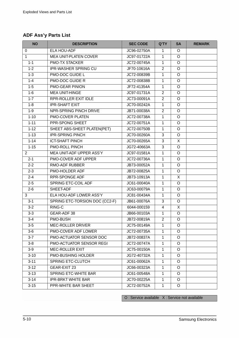
Exploded Views and Parts List
5-10 Samsung Electronics
ADF Ass’y Parts List
NO DESCRIPTION SEC CODE Q’TY SA REMARK
0 ELA HOU-ADF JC96-02750A 1 O
1 MEA UNIT-PLATEN COVER JC97-01722A 1 O
1-1 PMO-TX STACKER JC72-00745A 1 O
1-2 IPR-WASHER SPRING CU JF70-10616A 2 O
1-3 PMO-DOC GUIDE L JC72-00839B 1 O
1-4 PMO-DOC GUIDE R JC72-00838B 1 O
1-5 PMO-GEAR PINION JF72-41354A 1 O
1-6 MEA UNIT-HINGE JC97-01731A 2 O
1-7 RPR-ROLLER EXIT IDLE JC73-00091A 2 O
1-8 IPR-SHAFT EXIT JC70-00242A 1 O
1-9 NPR-SPRING PINCH DRIVE JB71-00038A 2 O
1-10 PMO-COVER PLATEN JC72-00738A 1 O
1-11 PPR-SPONG SHEET JC72-00751A 1 O
1-12 SHEET ABS-SHEET PLATEN(PET) JC72-00750B 1 O
1-13 IPR-SPRING PINCH JC70-00260A 3 O
1-14 ICT-SHAFT PINCH JC70-00265A 3 X
1-15 PMO-ROLL PINCH JG72-40663A 3 O
2 MEA UNIT-ADF UPPER ASS’Y JC97-01581A 1 O
2-1 PMO-COVER ADF UPPER JC72-00736A 1 O
2-2 RMO-ADF RUBBER JB73-00052A 1 O
2-3 PMO-HOLDER ADF JB72-00825A 1 O
2-4 RPR-SPONGE ADF JB73-10913A 1 X
2-5 SPRING ETC-COIL ADF JC61-00040A 1 O
2-6 SHEET-ADF JC63-00079A 1 O
3 ELA HOU-ADF LOWER ASS’Y JC81-00434A 1 O
3-1 SPRING ETC-TORSION DOC (CC2-F) JB61-00076A 3 O
3-2 RING-C 6044-000159 4 X
3-3 GEAR-ADF 38 JB66-00103A 1 O
3-4 PMO-BUSH JB72-00819A 2 O
3-5 MEC-ROLLER DRIVER JC75-00149A 1 O
3-6 PMO-COVER ADF LOWER JC72-00735A 1 O
3-7 PMO-ACTUATOR SENSOR DOC JB72-00837A 1 O
3-8 PMO-ACTUATOR SENSOR REGI JC72-00747A 1 O
3-9 MEC-ROLLER EXIT JC75-00150A 1 O
3-10 PMO-BUSHING HOLDER JG72-40732A 1 O
3-11 SPRING ETC-CLUTCH JC61-00062A 1 O
3-12 GEAR-EXIT 23 JC66-00323A 1 O
3-13 SPRING ETC-WHITE BAR JC61-00548A 1 O
3-14 IPR-BRKT WHITE BAR JC70-00225A 1 O
3-15 PPR-WHITE BAR SHEET JC72-00752A 1 O
O : Service available X : Service not available
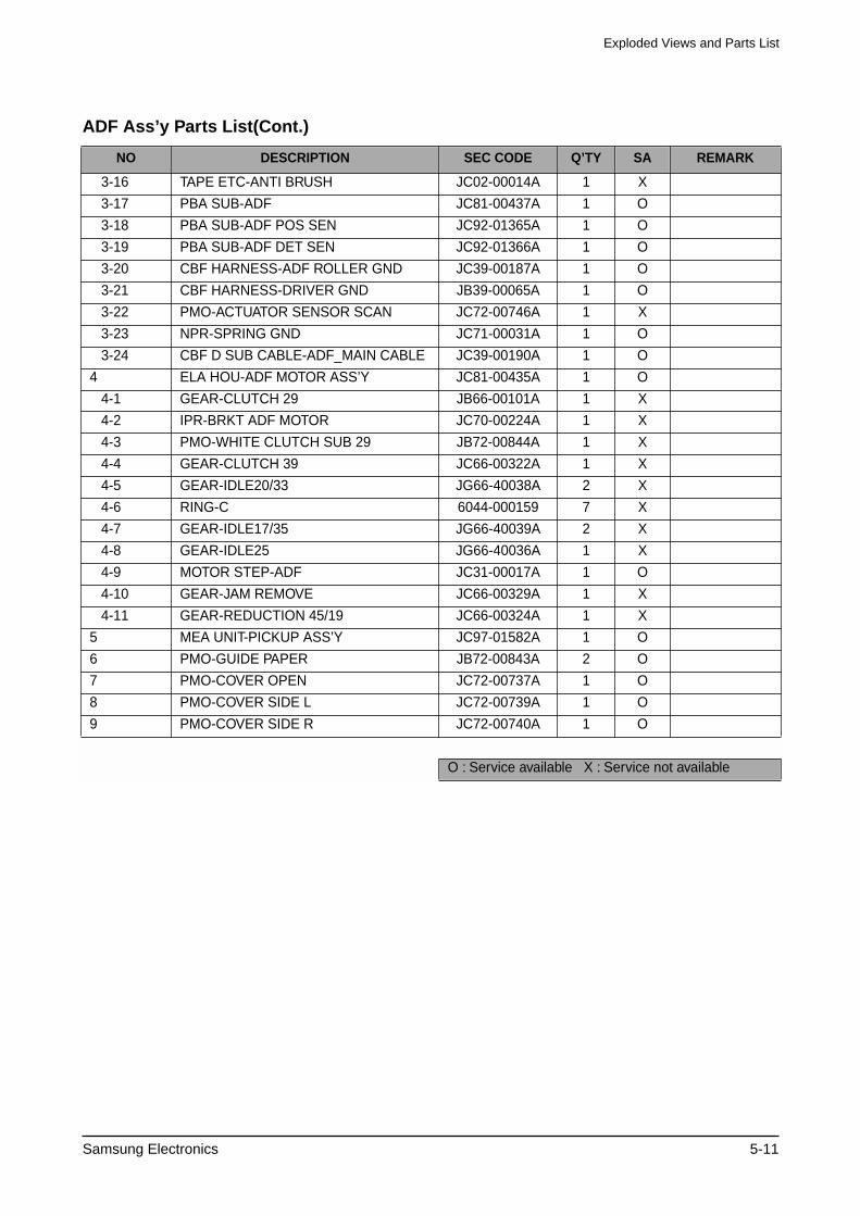
Exploded Views and Parts List
Samsung Electronics 5-11
ADF Ass’y Parts List(Cont.)
NO DESCRIPTION SEC CODE Q’TY SA REMARK
3-16 TAPE ETC-ANTI BRUSH JC02-00014A 1 X
3-17 PBA SUB-ADF JC81-00437A 1 O
3-18 PBA SUB-ADF POS SEN JC92-01365A 1 O
3-19 PBA SUB-ADF DET SEN JC92-01366A 1 O
3-20 CBF HARNESS-ADF ROLLER GND JC39-00187A 1 O
3-21 CBF HARNESS-DRIVER GND JB39-00065A 1 O
3-22 PMO-ACTUATOR SENSOR SCAN JC72-00746A 1 X
3-23 NPR-SPRING GND JC71-00031A 1 O
3-24 CBF D SUB CABLE-ADF_MAIN CABLE JC39-00190A 1 O
4 ELA HOU-ADF MOTOR ASS’Y JC81-00435A 1 O
4-1 GEAR-CLUTCH 29 JB66-00101A 1 X
4-2 IPR-BRKT ADF MOTOR JC70-00224A 1 X
4-3 PMO-WHITE CLUTCH SUB 29 JB72-00844A 1 X
4-4 GEAR-CLUTCH 39 JC66-00322A 1 X
4-5 GEAR-IDLE20/33 JG66-40038A 2 X
4-6 RING-C 6044-000159 7 X
4-7 GEAR-IDLE17/35 JG66-40039A 2 X
4-8 GEAR-IDLE25 JG66-40036A 1 X
4-9 MOTOR STEP-ADF JC31-00017A 1 O
4-10 GEAR-JAM REMOVE JC66-00329A 1 X
4-11 GEAR-REDUCTION 45/19 JC66-00324A 1 X
5 MEA UNIT-PICKUP ASS’Y JC97-01582A 1 O
6 PMO-GUIDE PAPER JB72-00843A 2 O
7 PMO-COVER OPEN JC72-00737A 1 O
8 PMO-COVER SIDE L JC72-00739A 1 O
9 PMO-COVER SIDE R JC72-00740A 1 O
O : Service available X : Service not available
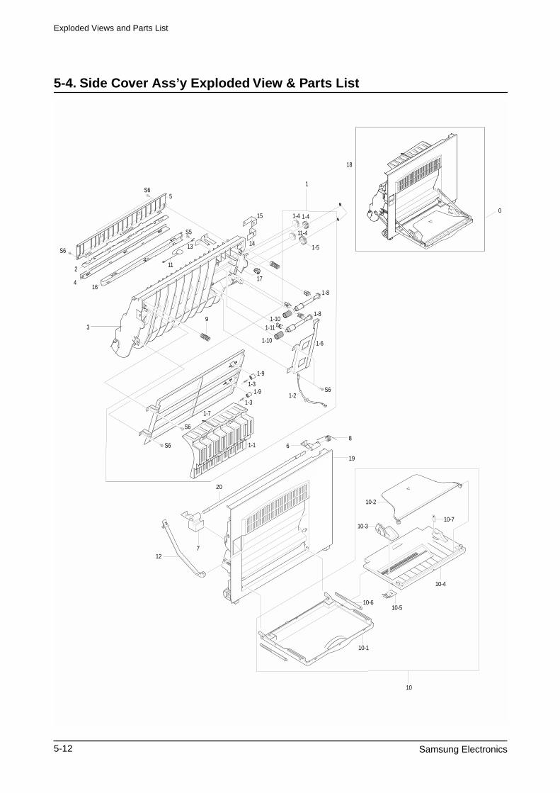
Exploded Views and Parts List
5-12 Samsung Electronics
5-4. Side Cover Ass’y Exploded View & Parts List
10-7
7
20
6
12
10-6
10-1
8
10-2
10-3
10-4
10-5
10
0
5S6
S6
S5
2
4
3
16
13
11
15
14
18
1-5
1-8
1-8
1-6
S6
1-10
1-2
1-10 1-11
1-9
1-91-3
1-3
1-7
S6
S6 1-1
11-4
1-4 1-4
17
1
9
19
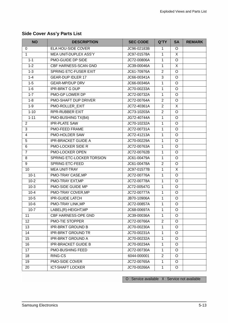
Exploded Views and Parts List
Samsung Electronics 5-13
Side Cover Ass’y Parts List
NO DESCRIPTION SEC CODE Q’TY SA REMARK
0 ELA HOU-SIDE COVER JC96-02183B 1 O
1 MEA UNIT-DUPLEX ASS’Y JC97-01578A 1 X
1-1 PMO-GUIDE DP SIDE JC72-00806A 1 O
1-2 CBF HARNESS-SCAN GND JC39-00046A 1 X
1-3 SPRING ETC-FUSER EXIT JC61-70976A 2 O
1-4 GEAR-DUP IDLER 17 JC66-00341A 3 O
1-5 GEAR-MP/DUP DRV JC66-00346A 1 O
1-6 IPR-BRKT G DUP JC70-00233A 1 O
1-7 PMO-GP LOWER DP JC72-00732A 1 O
1-8 PMO-SHAFT DUP DRIVER JC72-00764A 2 O
1-9 PMO-ROLLER_EXIT JC72-40361A 2 X
1-10 RPR-RUBBER EXIT JC73-10203A 2 O
1-11 PMO-BUSHING TX(B4) JG72-40744A 1 O
2 IPR-PLATE SAW JC70-10232A 1 O
3 PMO-FEED FRAME JC72-00731A 1 O
4 PMO-HOLDER SAW JC72-41213A 1 O
5 IPR-BRACKET GUIDE A JC70-00229A 1 O
6 PMO-LOCKER SIDE R JC72-00763A 1 O
7 PMO-LOCKER OPEN JC72-00762B 1 O
8 SPRING ETC-LOCKER TORSION JC61-00479A 1 O
9 SPRING ETC-FEED JC61-00478A 2 O
10 MEA UNIT-TRAY JC97-01577B 1 X
10-1 PMO-TRAY CASE,MP JC72-00776A 1 O
10-2 PMO-TRAY EXT,MP JC72-00778A 1 O
10-3 PMO-SIDE GUIDE MP JC72-00547G 1 O
10-4 PMO-TRAY COVER,MP JC72-00777A 1 O
10-5 IPR-GUIDE LATCH JB70-10906A 1 O
10-6 PMO-TRAY LINK,MP JC72-00857A 1 O
10-7 LABEL(R)-HEIGHT,MP JC68-00697A 1 O
11 CBF HARNESS-OPE GND JC39-00036A 1 O
12 PMO-TIE STOPPER JC72-00766A 2 O
13 IPR-BRKT GROUND B JC70-00230A 1 O
14 IPR-BRKT GROUND TR JC70-00231A 1 O
15 IPR-BRKT GROUND A JC70-00232A 1 O
16 IPR-BRACKET GUIDE B JC70-00234A 1 O
17 PMO-BUSHING FEED JC72-00730A 1 O
18 RING-CS 6044-000001 2 O
19 PMO-SIDE COVER JC72-00765A 1 O
20 ICT-SHAFT LOCKER JC70-00266A 1 O
O : Service available X : Service not available
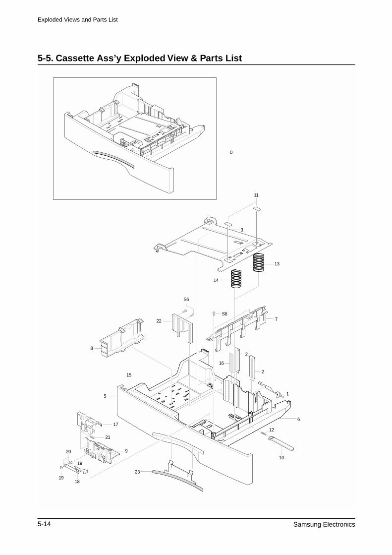
Exploded Views and Parts List
5-14 Samsung Electronics
5-5. Cassette Ass’y Exploded View & Parts List
0
3
11
14
13
7S6
S6
8
16
1
6
10
23
12
5
152
22
2
9
21
17
19
20
19
18
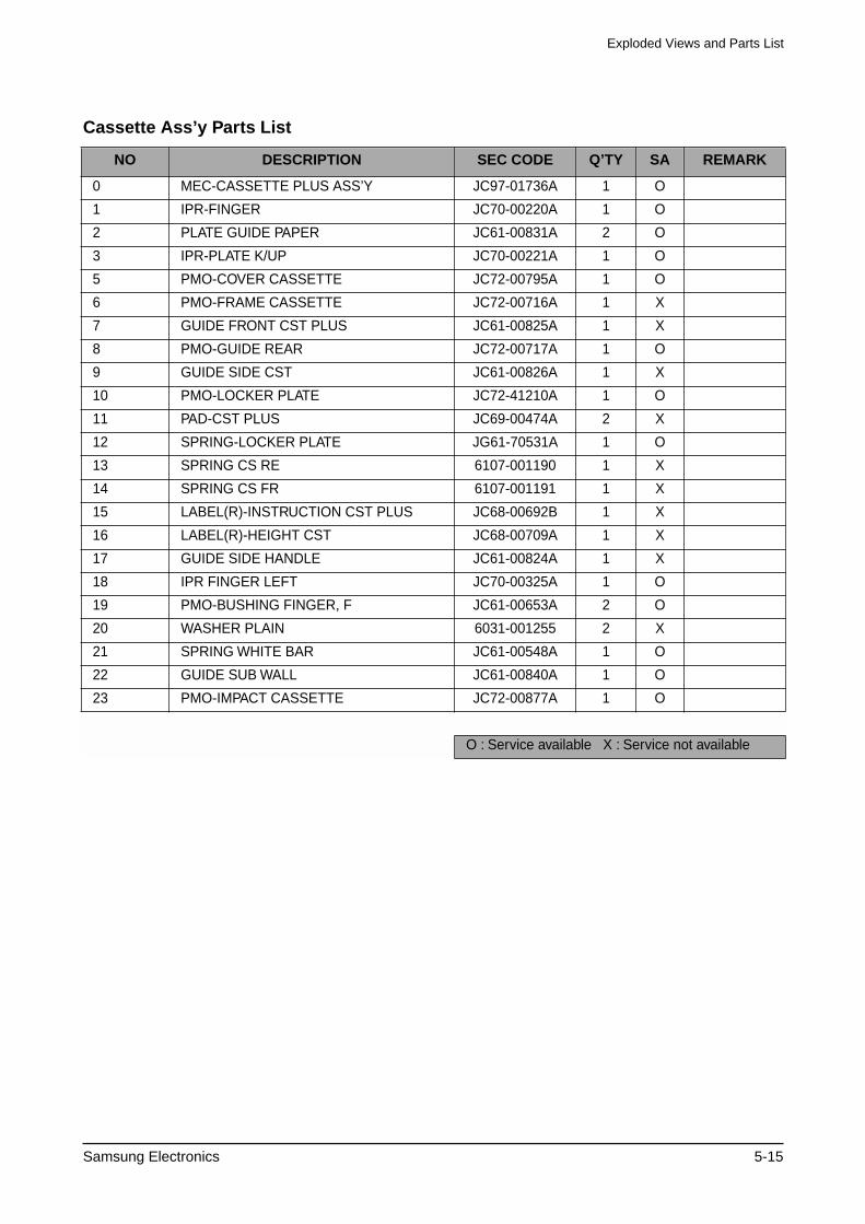
Exploded Views and Parts List
Samsung Electronics 5-15
Cassette Ass’y Parts List
NO DESCRIPTION SEC CODE Q’TY SA REMARK
0 MEC-CASSETTE PLUS ASS’Y JC97-01736A 1 O
1 IPR-FINGER JC70-00220A 1 O
2 PLATE GUIDE PAPER JC61-00831A 2 O
3 IPR-PLATE K/UP JC70-00221A 1 O
5 PMO-COVER CASSETTE JC72-00795A 1 O
6 PMO-FRAME CASSETTE JC72-00716A 1 X
7 GUIDE FRONT CST PLUS JC61-00825A 1 X
8 PMO-GUIDE REAR JC72-00717A 1 O
9 GUIDE SIDE CST JC61-00826A 1 X
10 PMO-LOCKER PLATE JC72-41210A 1 O
11 PAD-CST PLUS JC69-00474A 2 X
12 SPRING-LOCKER PLATE JG61-70531A 1 O
13 SPRING CS RE 6107-001190 1 X
14 SPRING CS FR 6107-001191 1 X
15 LABEL(R)-INSTRUCTION CST PLUS JC68-00692B 1 X
16 LABEL(R)-HEIGHT CST JC68-00709A 1 X
17 GUIDE SIDE HANDLE JC61-00824A 1 X
18 IPR FINGER LEFT JC70-00325A 1 O
19 PMO-BUSHING FINGER, F JC61-00653A 2 O
20 WASHER PLAIN 6031-001255 2 X
21 SPRING WHITE BAR JC61-00548A 1 O
22 GUIDE SUB WALL JC61-00840A 1 O
23 PMO-IMPACT CASSETTE JC72-00877A 1 O
O : Service available X : Service not available
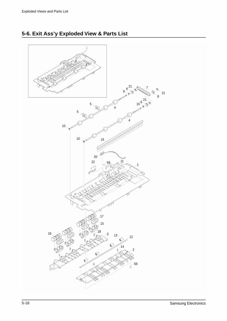
Exploded Views and Parts List
5-16 Samsung Electronics
5-6. Exit Ass’y Exploded View & Parts List
7
8
5
5
10
S6
20
22
4
6
610
10
4
9
21
21
21
111
16
17
15
183 13
19
12
142
S6
Exploded Views and Parts List
Samsung Electronics 5-17
Exit Ass’y Parts List
NO DESCRIPTION SEC CODE Q’TY SA REMARK
0 MEA UNIT-EXIT ASS’Y JC97-01643A 1 O
1 PMO-GUIDE-EXIT UPPER JC72-00708A 1 O
2 PMO-GUIDE-EXIT LOWER JC72-00710A 1 O
3 PMO-GUIDE-JAM REMOVE JC72-00712A 1 X
4 MEC-ROLLER EXIT DRV JC75-00127A 2 O
5 PMO-ROLLER DECURL JC72-00833A 4 O
6 PMO-PULLEY DUPLEX JC72-40980A 2 O
7 BELT-TIMING GEAR 6602-001084 1 O
8 GEAR-DUPLEX JC66-40912A 1 O
9 PMO-BEARING LARGE DP JC72-00885A 3 O
10 PMO-BEARING LARGE DP JC72-40978A 1 O
11 IPR-GROUND-EXIT JC70-00252A 1 X
12 ICT-SHAFT-EXIT LOWER ID JC70-00274A 1 X
13 PMO-ROLLER_EXIT JC72-40361A 4 X
14 SPRING ETC-EXIT ROLL FD JC61-70911A 2 X
15 HOLDER-EXIT(MC) JC61-00547A 4 X
16 PMO-ROLLER FD F JC72-41007A 4 O
17 PMO-ROLLER FD R JC72-41008A 4 O
18 SPRING ETC-EXIT LOWER IDLE JC61-00484A 4 X
19 MEC-BRUSH ANTISTATIC JC75-00095A 1 O
20 PBA SUB-BIN_FULL_SEN. JC92-01400A 1 O
21 RING-C 6044-000159 3 X
22 PMO-LEVER-STACKING JC72-00709A 1 O
O : Service available X : Service not available
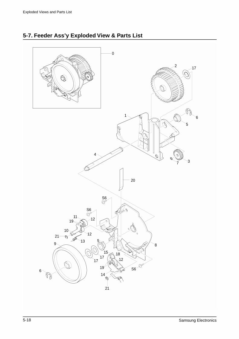
Exploded Views and Parts List
5-18 Samsung Electronics
5-7. Feeder Ass’y Exploded View & Parts List
2 17
6
5
37
1
0
4
20
8
S6
1112
S6
S6
12
13
1717
5
19
19
15 1812
14
21
6
9
2110
Exploded Views and Parts List
Samsung Electronics 5-19
Feeder Ass’y Parts List
NO DESCRIPTION SEC CODE Q’TY SA REMARK
0 MEA-FEED ASS’Y JC75-00143B 1 O
1 PMO-FRAME FEED JC72-00821A 1 X
2 GEAR-FEED JC66-00332A 1 O
3 GEAR-MP/DUP DRV JC66-00346A 1 X
4 ICT-SHAFT FEED JC70-00267A 1 X
5 BEARING-PICKUP JC66-10202A 2 X
6 RING-E 6044-000125 2 X
7 RING-CS 6044-000001 1 X
8 PMO-BRKT FEED JC72-00720A 1 X
9 PMO-ROLLER FEED JC72-00727A 1 O
10 PMO-HOLDER PINCH C JC72-00723A 1 X
11 PMO-HOLDER PINCH SUB JC72-00725A 1 X
12 PMO-ROLLER FEED L JC72-40261A 3 O
13 SPRING-FEED CAST JC61-00480A 1 X
14 PMO-HOLDER PINCH M JC72-00724A 1 X
15 PMO-SUB HOLDER FEED JC72-40266A 1 X
16 SPRING-FEED MP JC61-00481A 1 X
17 WASHER-PLAIN 6031-000021 3 X
18 PMO-ROLLER FEED S JC72-40262A 1 X
19 IPR-SHAFT FEED IDLER JC70-10230A 4 X
20 SHEET FEEDER JC63-00259A 1 X
21 E-RING 6044-000159 2 X Ø3
O : Service available X : Service not available
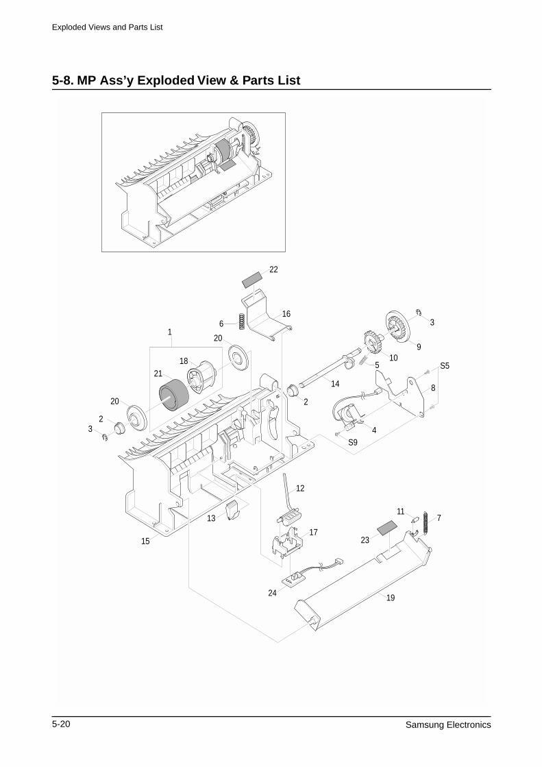
Exploded Views and Parts List
5-20 Samsung Electronics
5-8. MP Ass’y Exploded View & Parts List
18
1
21
22
166
20
20
23
2
14
510
9
3
S5
8
4S9
12
17
24
13
23
117
19
15
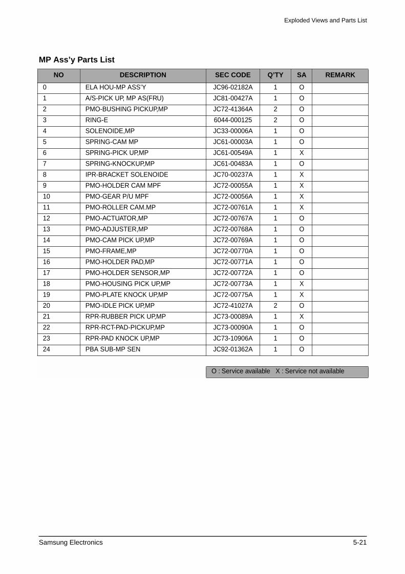
Exploded Views and Parts List
Samsung Electronics 5-21
MP Ass’y Parts List
NO DESCRIPTION SEC CODE Q’TY SA REMARK
0 ELA HOU-MP ASS’Y JC96-02182A 1 O
1 A/S-PICK UP, MP AS(FRU) JC81-00427A 1 O
2 PMO-BUSHING PICKUP,MP JC72-41364A 2 O
3 RING-E 6044-000125 2 O
4 SOLENOIDE,MP JC33-00006A 1 O
5 SPRING-CAM MP JC61-00003A 1 O
6 SPRING-PICK UP,MP JC61-00549A 1 X
7 SPRING-KNOCKUP,MP JC61-00483A 1 O
8 IPR-BRACKET SOLENOIDE JC70-00237A 1 X
9 PMO-HOLDER CAM MPF JC72-00055A 1 X
10 PMO-GEAR P/U MPF JC72-00056A 1 X
11 PMO-ROLLER CAM.MP JC72-00761A 1 X
12 PMO-ACTUATOR,MP JC72-00767A 1 O
13 PMO-ADJUSTER,MP JC72-00768A 1 O
14 PMO-CAM PICK UP,MP JC72-00769A 1 O
15 PMO-FRAME,MP JC72-00770A 1 O
16 PMO-HOLDER PAD,MP JC72-00771A 1 O
17 PMO-HOLDER SENSOR,MP JC72-00772A 1 O
18 PMO-HOUSING PICK UP,MP JC72-00773A 1 X
19 PMO-PLATE KNOCK UP,MP JC72-00775A 1 X
20 PMO-IDLE PICK UP,MP JC72-41027A 2 O
21 RPR-RUBBER PICK UP,MP JC73-00089A 1 X
22 RPR-RCT-PAD-PICKUP,MP JC73-00090A 1 O
23 RPR-PAD KNOCK UP,MP JC73-10906A 1 O
24 PBA SUB-MP SEN JC92-01362A 1 O
O : Service available X : Service not available
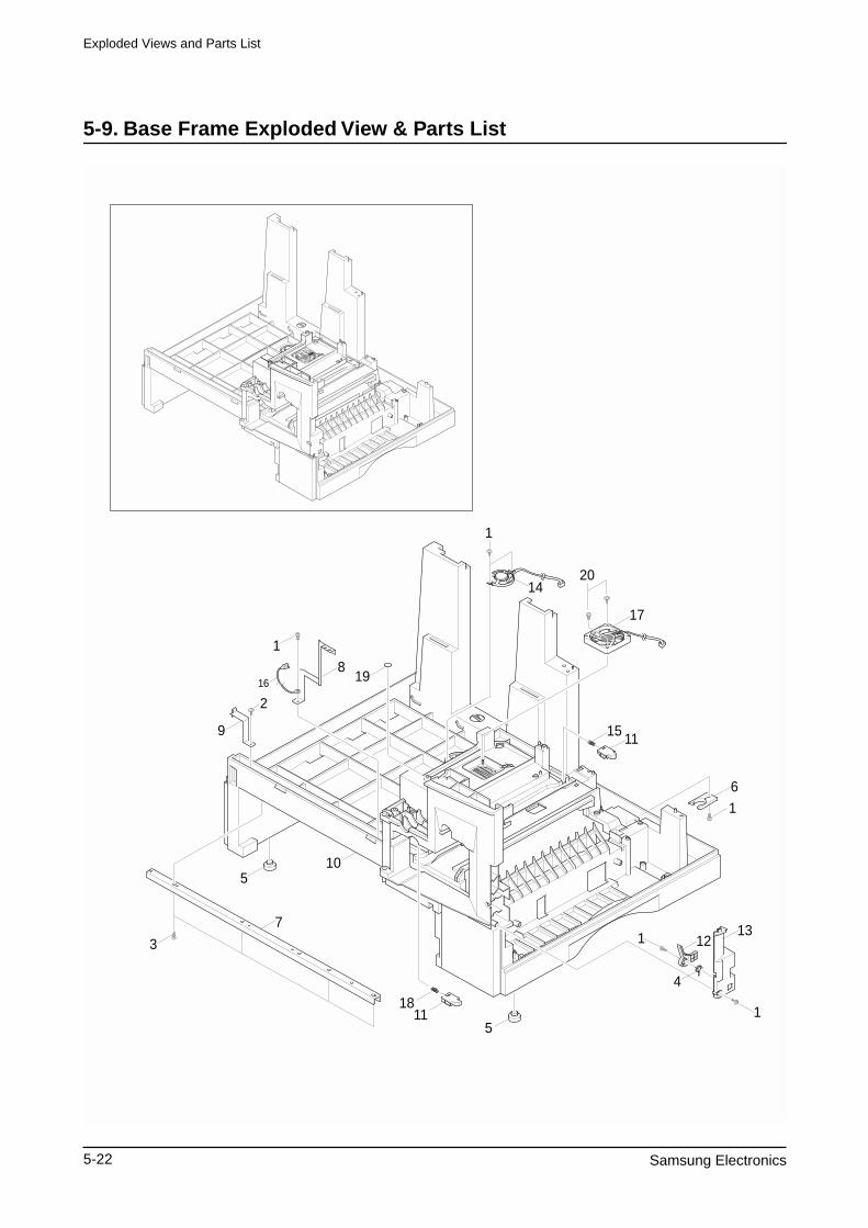
Exploded Views and Parts List
5-22 Samsung Electronics
5-9. Base Frame Exploded View & Parts List
1811
1
2014
15
17
11
6
1
4
1213
1
1
5
510
7
3
1
819
2
9
16
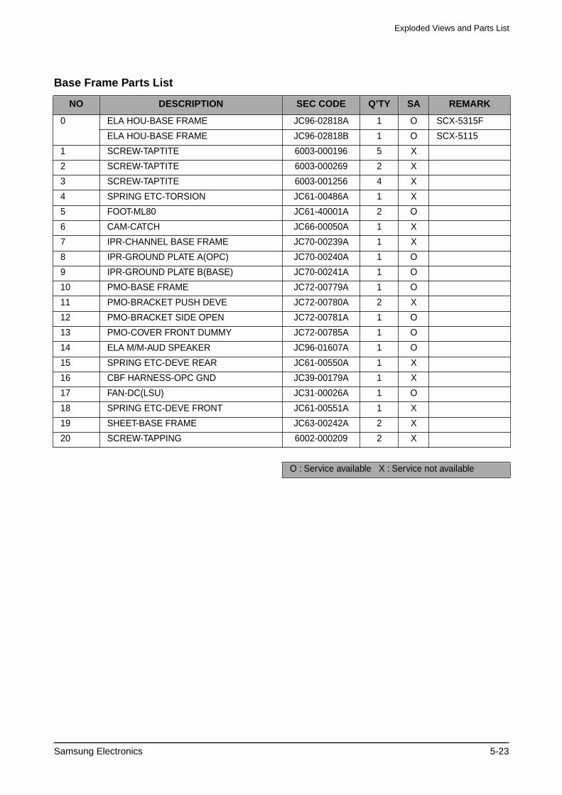
Exploded Views and Parts List
Samsung Electronics 5-23
Base Frame Parts List
NO DESCRIPTION SEC CODE Q’TY SA REMARK
0 ELA HOU-BASE FRAME JC96-02818A 1 O SCX-5315F
ELA HOU-BASE FRAME JC96-02818B 1 O SCX-5115
1 SCREW-TAPTITE 6003-000196 5 X
2 SCREW-TAPTITE 6003-000269 2 X
3 SCREW-TAPTITE 6003-001256 4 X
4 SPRING ETC-TORSION JC61-00486A 1 X
5 FOOT-ML80 JC61-40001A 2 O
6 CAM-CATCH JC66-00050A 1 X
7 IPR-CHANNEL BASE FRAME JC70-00239A 1 X
8 IPR-GROUND PLATE A(OPC) JC70-00240A 1 O
9 IPR-GROUND PLATE B(BASE) JC70-00241A 1 O
10 PMO-BASE FRAME JC72-00779A 1 O
11 PMO-BRACKET PUSH DEVE JC72-00780A 2 X
12 PMO-BRACKET SIDE OPEN JC72-00781A 1 O
13 PMO-COVER FRONT DUMMY JC72-00785A 1 O
14 ELA M/M-AUD SPEAKER JC96-01607A 1 O
15 SPRING ETC-DEVE REAR JC61-00550A 1 X
16 CBF HARNESS-OPC GND JC39-00179A 1 X
17 FAN-DC(LSU) JC31-00026A 1 O
18 SPRING ETC-DEVE FRONT JC61-00551A 1 X
19 SHEET-BASE FRAME JC63-00242A 2 X
20 SCREW-TAPPING 6002-000209 2 X
O : Service available X : Service not available
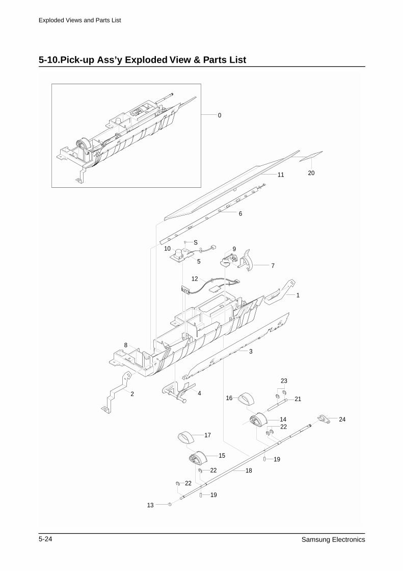
Exploded Views and Parts List
5-24 Samsung Electronics
5-10.Pick-up Ass’y Exploded View & Parts List
6
11 20
5
S10
42
12
9
7
3
1
8
0
13
2422
22
14
23
15
18
17
16 21
19
22
19
Exploded Views and Parts List
Samsung Electronics 5-25
Pick-up Ass’y Parts List
NO DESCRIPTION SEC CODE Q’TY SA REMARK
0 ELA HOU-PICKUP PLUS ASS’Y JC96-02715B 1 O
1 IPR-GND FEED JC70-00238A 1 X
2 IPR-GND INPUT JC70-00235A 1 O
3 IPR-GUIDE INPUT JC70-00222A 1 O
4 PMO-ACTUATOR NO PAPER JC72-01313A 1 X
5 PBA SUB-TONER_TX JC92-01359A 1 O
6 PBA SUB-PTL JC92-01361A 1 O
7 PMO-FEED SENSOR JC72-00721A 1 X
8 PMO-GUIDE PAPER JC72-00722A 1 O
9 PMO-HOLDER SENSOR FEED JC72-00726A 1 X
10 PMO-LENS TONER SENSOR JC72-00803A 1 X
11 PMO-PTL PATH JC72-00822A 1 X
12 PBA SUB-FEED+P.EMP SEN. JC92-01363A 1 O
13 PMO-BUSHING_P/U,MP JC72-41364A 1 O
14 HOUSING-PICKUP LARGE JC61-00822A 1 X
15 HOUSING-PICKUP SMALL JC61-00823A 1 X
16 RPR RUBBER PICKUP JC73-00145A 1 X
17 RUBBER PICKUP SMALL JC73-00163A 1 O
18 SHAFT-PICKUP CST JC66-00672A 1 X
19 SHAFT PIN ADF JB70-00168A 1 X
20 SHEET-PTL PATH JC63-00083A 1 X
21 SHAFT-SUB-PICKUP JC66-00596A 1 X
22 RING-E ID4 6044-000125 4 O
23 RING-E ID5 6044-000231 2 O
24 PMO-BEARING SHAFT JC72-41191A 1 O
S SCREW-TAPTITE 6003-000119 1 X
O : Service available X : Service not available
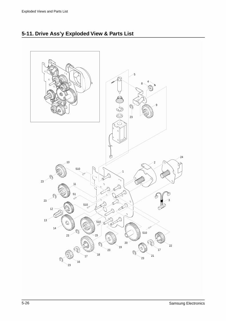
Exploded Views and Parts List
5-26 Samsung Electronics
5-11. Drive Ass’y Exploded View & Parts List
S101
2
24
10
23
23
11
S1
S10
S10
12
13
14
23 15
23
1817
1623
19
20
2321
1722
S10
5
84
9
23
3
Exploded Views and Parts List
Samsung Electronics 5-27
Drive Ass’y Parts List
NO DESCRIPTION SEC CODE Q’TY SA REMARK
0 ELA HOU-DRIVE(15PPM) JC96-02741A 1 O
1 IPR-BRKT MOTOR JC70-00257A 1 X
2 MOTOR STEP-MAIN JC31-00020B 2 O M49SP-2K
3 CBF HARNESS-MOTOR JC39-00165A 1 O
4 RING-C 6044-000159 1 O
5 SOLENOID-DUPLEX JC33-00008A 1 O
6 SPRING ETC-SOLENOID DP JC61-70915A 1 X
7 IPR-LINK SOLENOID JC70-00258A 1 X
8 GEAR-EXIT/U,ID JC66-40211B 1 O
9 GEAR-SWING DRV JC66-00349A 1 X
10 GEAR-35/19 JC66-00350A 1 X
11 GEAR-71/23 JC66-00345A 1 X
12 GEAR-DEVE DRV JC66-00338A 1 X
13 PMO-DEV/COUPLING JC72-00743A 1 X
14 GEAR-RDCN,OPC JC66-00351A 1 X
15 GEAR-86/23 JC66-00337A 1 X
16 GEAR-RDCN FEED OUTER JC66-00343A 1 X
17 GEAR-HUB CLUTCH JC66-00340A 2 X
18 GEAR-RDCN FEED INNER JC66-00342A 1 X
19 GEAR-FEED DRV JC66-00348A 1 X
20 GEAR-OPC DRV JC66-00347A 1 X
21 GEAR-GEAR FUSER DRV OUTER JC66-00334A 1 X
22 GEAR-FUSER DRV INNER JC66-00333A 1 X
23 RING-E 6044-000231 7 O
24 MOTOR STEP-MAIN JC31-00028B 1 O M4PSP-2NK
O : Service available X : Service not available
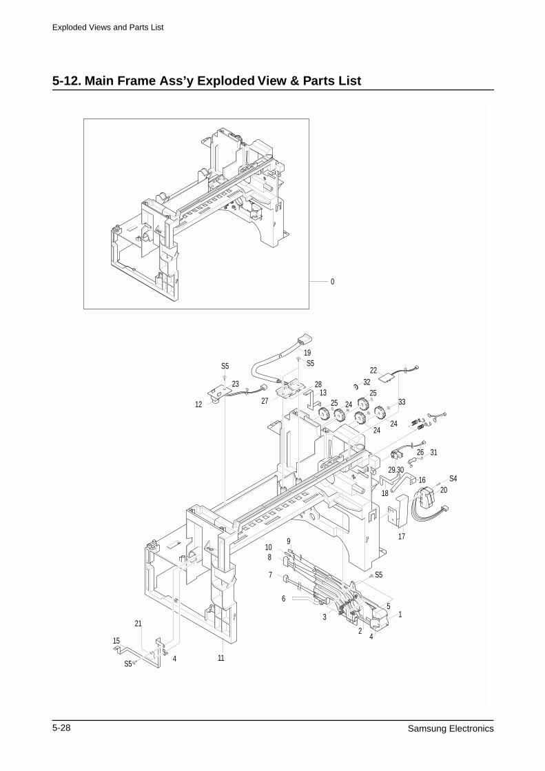
Exploded Views and Parts List
5-28 Samsung Electronics
5-12. Main Frame Ass’y Exploded View & Parts List
31
32
12
23
S5
15
S5
21
4 11
109
8
6
7
3
2
5
S5
1
4
17
20S4
18
16
26
19S5
0
27
2813
2424
33
22
2525
24
29.30
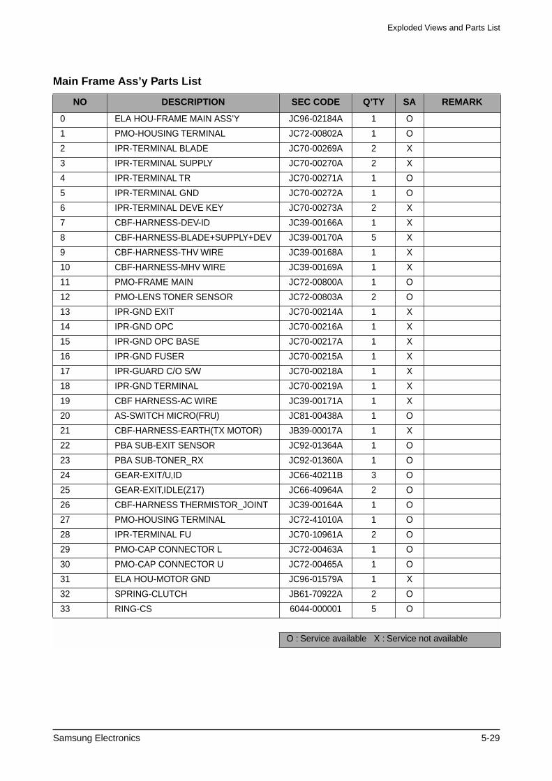
Exploded Views and Parts List
Samsung Electronics 5-29
Main Frame Ass’y Parts List
NO DESCRIPTION SEC CODE Q’TY SA REMARK
0 ELA HOU-FRAME MAIN ASS’Y JC96-02184A 1 O
1 PMO-HOUSING TERMINAL JC72-00802A 1 O
2 IPR-TERMINAL BLADE JC70-00269A 2 X
3 IPR-TERMINAL SUPPLY JC70-00270A 2 X
4 IPR-TERMINAL TR JC70-00271A 1 O
5 IPR-TERMINAL GND JC70-00272A 1 O
6 IPR-TERMINAL DEVE KEY JC70-00273A 2 X
7 CBF-HARNESS-DEV-ID JC39-00166A 1 X
8 CBF-HARNESS-BLADE+SUPPLY+DEV JC39-00170A 5 X
9 CBF-HARNESS-THV WIRE JC39-00168A 1 X
10 CBF-HARNESS-MHV WIRE JC39-00169A 1 X
11 PMO-FRAME MAIN JC72-00800A 1 O
12 PMO-LENS TONER SENSOR JC72-00803A 2 O
13 IPR-GND EXIT JC70-00214A 1 X
14 IPR-GND OPC JC70-00216A 1 X
15 IPR-GND OPC BASE JC70-00217A 1 X
16 IPR-GND FUSER JC70-00215A 1 X
17 IPR-GUARD C/O S/W JC70-00218A 1 X
18 IPR-GND TERMINAL JC70-00219A 1 X
19 CBF HARNESS-AC WIRE JC39-00171A 1 X
20 AS-SWITCH MICRO(FRU) JC81-00438A 1 O
21 CBF-HARNESS-EARTH(TX MOTOR) JB39-00017A 1 X
22 PBA SUB-EXIT SENSOR JC92-01364A 1 O
23 PBA SUB-TONER_RX JC92-01360A 1 O
24 GEAR-EXIT/U,ID JC66-40211B 3 O
25 GEAR-EXIT,IDLE(Z17) JC66-40964A 2 O
26 CBF-HARNESS THERMISTOR_JOINT JC39-00164A 1 O
27 PMO-HOUSING TERMINAL JC72-41010A 1 O
28 IPR-TERMINAL FU JC70-10961A 2 O
29 PMO-CAP CONNECTOR L JC72-00463A 1 O
30 PMO-CAP CONNECTOR U JC72-00465A 1 O
31 ELA HOU-MOTOR GND JC96-01579A 1 X
32 SPRING-CLUTCH JB61-70922A 2 O
33 RING-CS 6044-000001 5 O
O : Service available X : Service not available
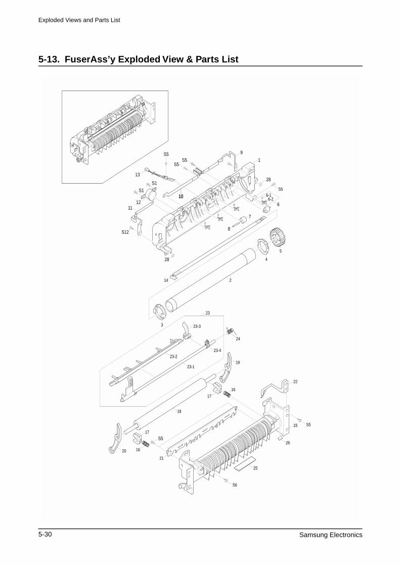
Exploded Views and Parts List
5-30 Samsung Electronics
5-13. FuserAss’y Exploded View & Parts List
24
23
23-1
23-423-2
18
19
1617
17
22
15
25
26
S6
S5
21
1620
S5
S5
13
11
S12
28
S5S5
S5
10
9
1
28
6
7
8
6-16-2
14
5
4
2
3 23-3
S1
S1
1012
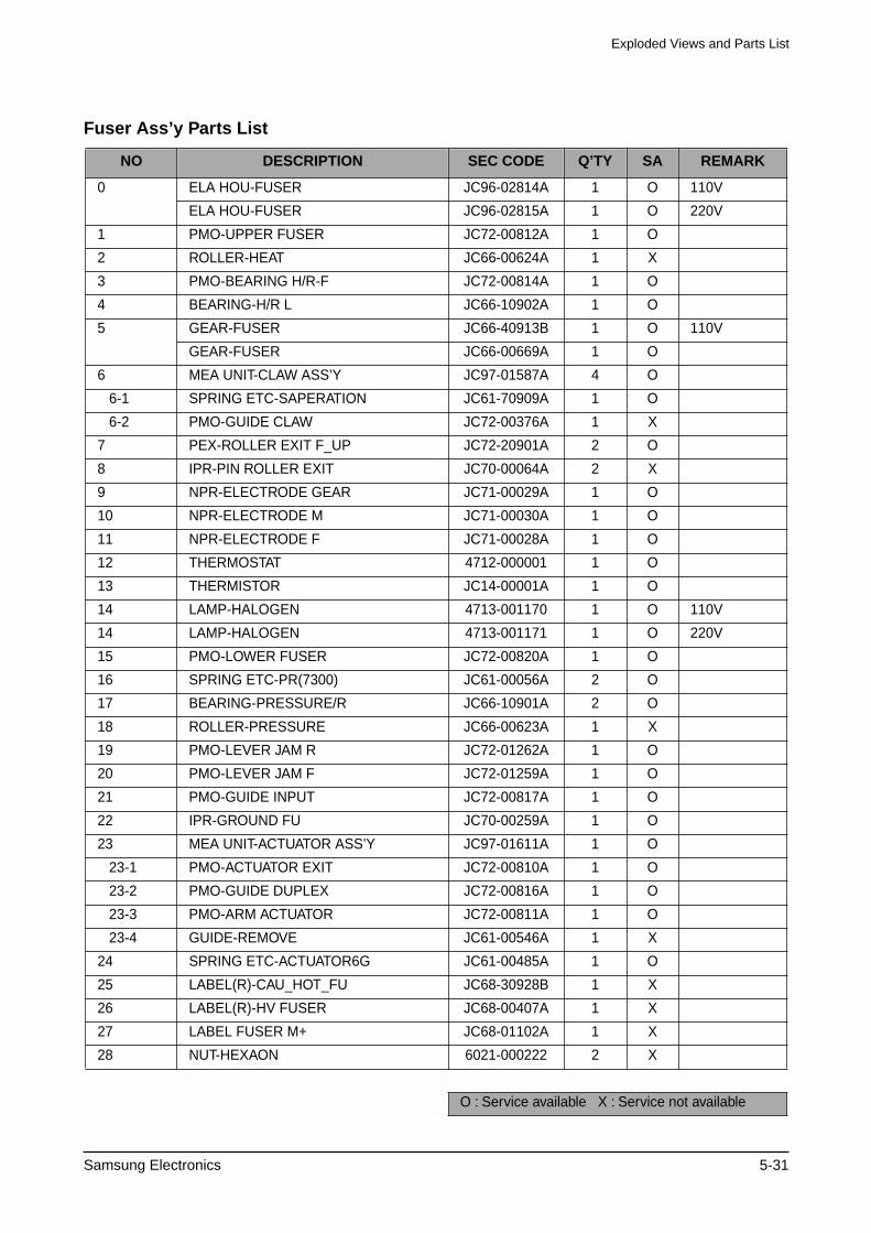
Exploded Views and Parts List
Samsung Electronics 5-31
Fuser Ass’y Parts List
NO DESCRIPTION SEC CODE Q’TY SA REMARK
0 ELA HOU-FUSER JC96-02814A 1 O 110V
ELA HOU-FUSER JC96-02815A 1 O 220V
1 PMO-UPPER FUSER JC72-00812A 1 O
2 ROLLER-HEAT JC66-00624A 1 X
3 PMO-BEARING H/R-F JC72-00814A 1 O
4 BEARING-H/R L JC66-10902A 1 O
5 GEAR-FUSER JC66-40913B 1 O 110V
GEAR-FUSER JC66-00669A 1 O
6 MEA UNIT-CLAW ASS’Y JC97-01587A 4 O
6-1 SPRING ETC-SAPERATION JC61-70909A 1 O
6-2 PMO-GUIDE CLAW JC72-00376A 1 X
7 PEX-ROLLER EXIT F_UP JC72-20901A 2 O
8 IPR-PIN ROLLER EXIT JC70-00064A 2 X
9 NPR-ELECTRODE GEAR JC71-00029A 1 O
10 NPR-ELECTRODE M JC71-00030A 1 O
11 NPR-ELECTRODE F JC71-00028A 1 O
12 THERMOSTAT 4712-000001 1 O
13 THERMISTOR JC14-00001A 1 O
14 LAMP-HALOGEN 4713-001170 1 O 110V
14 LAMP-HALOGEN 4713-001171 1 O 220V
15 PMO-LOWER FUSER JC72-00820A 1 O
16 SPRING ETC-PR(7300) JC61-00056A 2 O
17 BEARING-PRESSURE/R JC66-10901A 2 O
18 ROLLER-PRESSURE JC66-00623A 1 X
19 PMO-LEVER JAM R JC72-01262A 1 O
20 PMO-LEVER JAM F JC72-01259A 1 O
21 PMO-GUIDE INPUT JC72-00817A 1 O
22 IPR-GROUND FU JC70-00259A 1 O
23 MEA UNIT-ACTUATOR ASS’Y JC97-01611A 1 O
23-1 PMO-ACTUATOR EXIT JC72-00810A 1 O
23-2 PMO-GUIDE DUPLEX JC72-00816A 1 O
23-3 PMO-ARM ACTUATOR JC72-00811A 1 O
23-4 GUIDE-REMOVE JC61-00546A 1 X
24 SPRING ETC-ACTUATOR6G JC61-00485A 1 O
25 LABEL(R)-CAU_HOT_FU JC68-30928B 1 X
26 LABEL(R)-HV FUSER JC68-00407A 1 X
27 LABEL FUSER M+ JC68-01102A 1 X
28 NUT-HEXAON 6021-000222 2 X
O : Service available X : Service not available
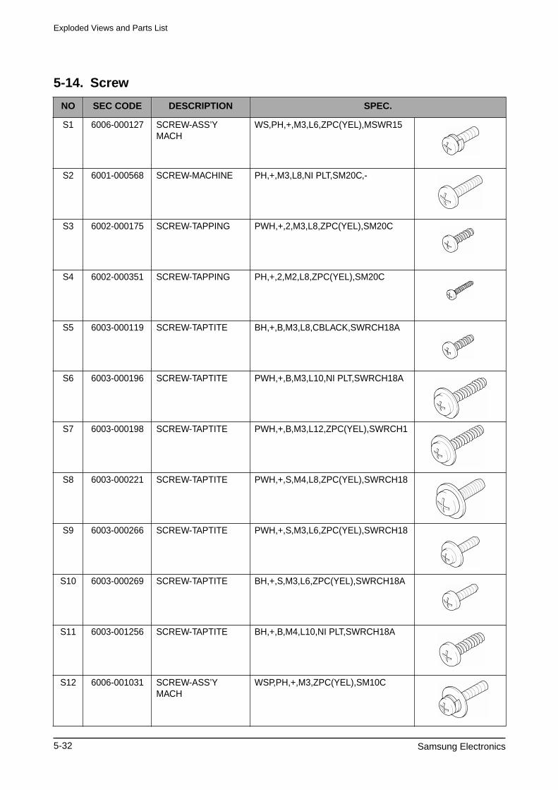
Exploded Views and Parts List
5-32 Samsung Electronics
5-14. Screw
NO SEC CODE DESCRIPTION SPEC.
S1 6006-000127 SCREW-ASS’Y MACH
WS,PH,+,M3,L6,ZPC(YEL),MSWR15
S2 6001-000568 SCREW-MACHINE PH,+,M3,L8,NI PLT,SM20C,-
S3 6002-000175 SCREW-TAPPING PWH,+,2,M3,L8,ZPC(YEL),SM20C
S4 6002-000351 SCREW-TAPPING PH,+,2,M2,L8,ZPC(YEL),SM20C
S5 6003-000119 SCREW-TAPTITE BH,+,B,M3,L8,CBLACK,SWRCH18A
S6 6003-000196 SCREW-TAPTITE PWH,+,B,M3,L10,NI PLT,SWRCH18A
S7 6003-000198 SCREW-TAPTITE PWH,+,B,M3,L12,ZPC(YEL),SWRCH1
S8 6003-000221 SCREW-TAPTITE PWH,+,S,M4,L8,ZPC(YEL),SWRCH18
S9 6003-000266 SCREW-TAPTITE PWH,+,S,M3,L6,ZPC(YEL),SWRCH18
S10 6003-000269 SCREW-TAPTITE BH,+,S,M3,L6,ZPC(YEL),SWRCH18A
S11 6003-001256 SCREW-TAPTITE BH,+,B,M4,L10,NI PLT,SWRCH18A
S12 6006-001031 SCREW-ASS’Y MACH
WSP,PH,+,M3,ZPC(YEL),SM10C
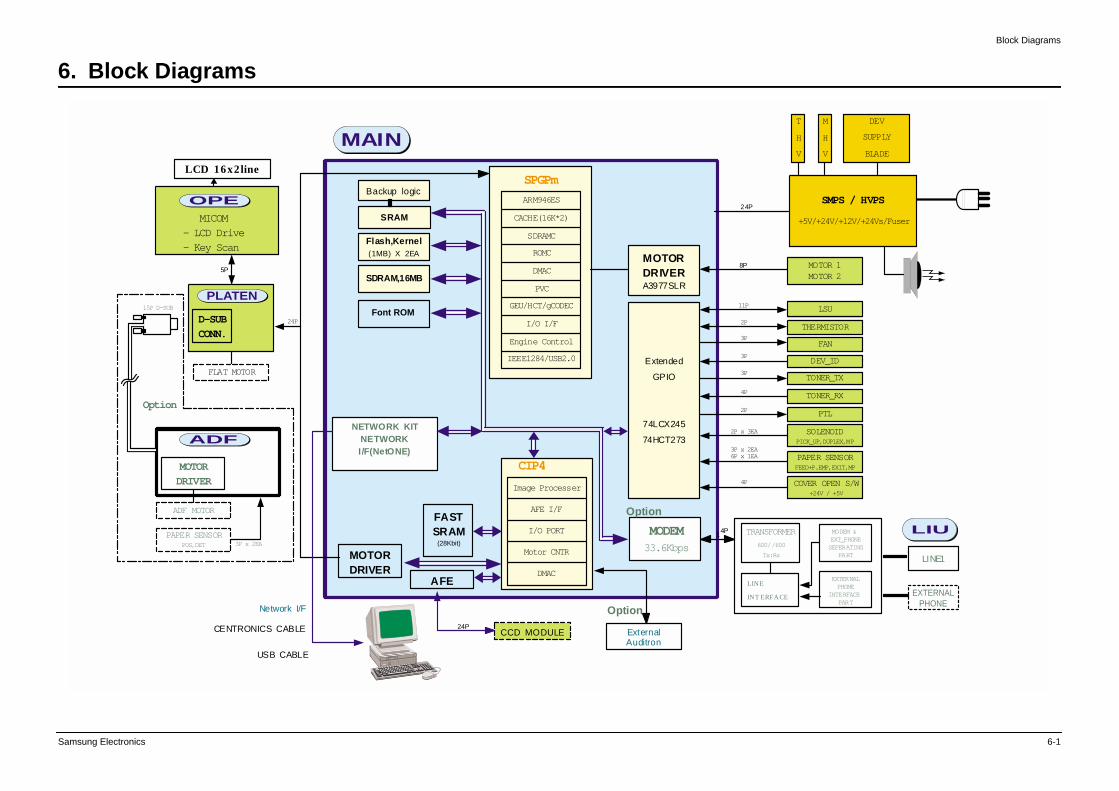
Block Diagrams
Samsung Electronics 6-1
6. Block Diagrams
MODEM33.6Kbps
SPGPm
ARM946ES
CACHE(16K*2)
SDRAMC
ROMC
DMAC
PVC
GEU/HCT/gCODEC
I/O I/F
Engine Control
IEEE1284/USB2.0 Extended
GPIO
74LCX245
74HCT273
FASTSRAM
(28Kbit)
MOTORDRIVER
AFE
SRAM
Backup logic
Flash,Kernel(1MB) X 2EA
SDRAM,16MB
MOTORDRIVERA3977SLR
MOTOR 1MOTOR 2
SMPS / HVPS
+5V/+24V/+12V/+24Vs/Fuser
M
H
V
DEV
SUPPLY
BLADE
T
H
V
8P
FAN
TONER_TX
TONER_RX
PTL
SOLENOIDPICK_UP,DUPLEX,MP
PAPER SENSORFEED+P.EMP,EXIT,MP
COVER OPEN S/W+24V / +5V
LSU11P
THERMISTOR2P
3P
DEV_ID3P
3P
4P
2P
2P x 3EA
4P
3P x 2EA6P x 1EA
CENTRONICS CABLE
USB CABLE
CCD MODULE
24P
24P
24P
14P
5P
FLAT MOTOR
MOTORDRIVER
ADF MOTOR
PAPER SENSORPOS,DET 3P x 2EA
15P D-SUB
Option
CIP4
Image Processer
AFE I/F
I/O PORT
Motor CNTR
DMAC
NETWORK KITNETWORKI/F(NetONE)
Font ROM
Option
MICOM- LCD Drive- Key Scan
LCD 16x2line
ExternalAuditron
OptionNetwork I/F
D-SUB
CONN.
MODEM &EXT_PHONESEPERATING
PART
EXTERNALPHONE
INTERFACEPART
600//600
Tx:Rx
TRANSFORMER
LINE
INT ERFACE
MAIN
OPE
PLATEN
ADF
LIU
EXTERNALPHONE
LINE1
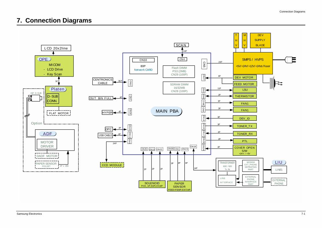
Connection Diagrams
Samsung Electronics 7-1
7. Connection Diagrams
Flash DIMMPS3 (2MB)
CN29 (100P)
SDRAM DIMM16/32MB
CN28 (100P)
DEV MOTOR
SMPS / HVPS
+5V/+24V/+12V/+24Vs /Fuser
M
H
V
DEV
SUPPLY
BLADE
T
H
V
FAN1
TONER_TX
TONER_RX
PTL
SOLENOIDPICK_UP,DUPLEX,MP
PAPERSEN SOR
FEED+P.EMP,EXIT,MP
COVER OPENS/W
+24V / +5V
LSU11P
THERMISTOR2P
3P
DEV_ID3P
3P
4P
2P
4P
CCD MODULE
24P
24P
24P
14P
FLAT MOTOR
5P
15P D-SUB
Option
MOTORDRIVER
3P x 2EA
MICOM- LCD Drive
- Key Scan
L CD 20x2line
OPE
D-SUBCONN.
MODEMEXT_PHONESEPRATING
PART
EXTERNALPHONE
INTERFACEPART
EXTERNALPHONE
600/ / 600
Tx: Rx
TRANSFORMER
LINE
INT ERFACE
LINE1
FAN13P
FEED MOTOR
8P
CN
27
CN
17
CN
5C
N8
CN
19
CN
9C
N6
CN
2C
N1
4C
N2
4C
N2
6
CN18
USB CABLE
CN13 CN22CN25 CN23CN1CN20
Network CARD
CN10
80P
OU T BIN FULL
OPC
HYPER
CN
26
CN
16
CN
12C
N1
1C
N3
CN
7
36P
4P
4P
2P
4P
2P 2P
6P
2P
3P 3P
CN4
SCA N
MAIN PBA
CENTRONICSCABLE
LIU
Platen
ADF
DADF MOTOR
PAPER SENSORPOS,DET
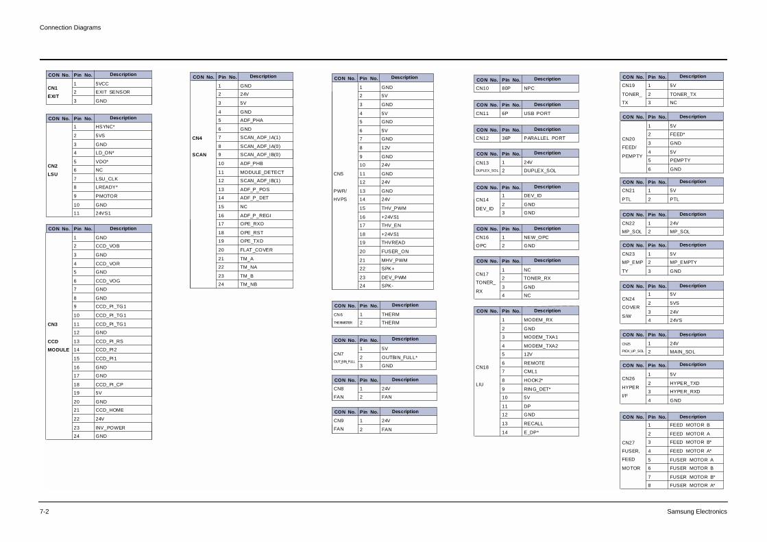
Connection Diagrams
7-2 Samsung Electronics
CON No. Pin No. Description
CN1
EXIT
1 5VCC
2 EXIT SENSOR
3 GND
CON No. Pin No.
CON No. Pin No.
CON No. Pin No.
CON No. Pin No.
CON No. Pin No.
CON No. Pin No.
CON No. Pin No.
CON No. Pin No.
CON No. Pin No.
CON No. Pin No.
CON No. Pin No.
CON No. Pin No.
CON No. Pin No.
CON No. Pin No.
CON No. Pin No.
CON No. Pin No.
CON No. Pin No.
CON No. Pin No.
CON No. Pin No.
CON No. Pin No.
CON No. Pin No.
CON No. Pin No.
CON No. Pin No.
CON No. Pin No.
CON No. Pin No.
CN2
LSU
1 HSYNC*
2 5VS
3 GND
4 LD_ON*
5 VDO*
6 NC
7 LSU_CLK
8 LREADY*
9 PMOTOR
10 GND
11 24VS1
CN3
CCD
MODULE
1 GND
2 CCD_VOB
3 GND
4 CCD_VOR
5 GND
6 CCD_VOG
7 GND
8 GND
9 CCD_PI_TG1
10 CCD_PI_TG1
11 CCD_PI_TG1
12 GND
13 CCD_PI_RS
14 CCD_PI2
15 CCD_PI1
16 GND
17 GND
18 CCD_PI_CP
19 5V
20 GND
21 CCD_HOME
22 24V
23 INV_POWER
24 GND
CN4
SCAN
1 GND
2 24V
3 5V
4 GND
5 ADF_PHA
6 GND
7 SCAN_ADF_IA(1)
8 SCAN_ADF_IA(0)
9 SCAN_ADF_IB(0)
10 ADF_PHB
11 MODULE_DETECT
12 SCAN_ADF_IB(1)
13 ADF_P_POS
14 ADF_P_DET
15 NC
16 ADF_P_REGI
17 OPE_RXD
18 OPE_RST
19 OPE_TXD
20 FLAT_COVER
21 TM_A
22 TM_NA
23 TM_B
24 TM_NB
CN5
PWR/
HVPS
1 GND
2 5V
3 GND
4 5V
5 GND
6 5V
7 GND
8 12V
9 GND
10 24V
11 GND
12 24V
13 GND
14 24V
15 THV_PWM
16 +24VS1
17 THV_EN
18 +24VS1
19 THVREAD
20 FUSER_ON
21 MHV_PWM
22 SPK+
23 DEV_PWM
24 SPK-
CN6
THERMISTER
1 THERM
2 THERM
CN7
OUT_BIN_FULL
1 5V
2 OUTBIN_FULL*
3 GND
CN8
FAN
1 24V
2 FAN
CN9
FAN
1 24V
2 FAN
CN10 80P NPC
CN11 6P USB PORT
CN12 36P PARALLEL PORT
CN13
DUPLEX_SOL
1 24V
2 DUPLEX_SOL
CN14
DEV_ID
1 DEV_ID
2 GND
3 GND
CN16
OPC
1 NEW_OPC
2 GND
CN17
TONER_
RX
1 NC
2 TONER_RX
3 GND
4 NC
CN18
LIU
1 MODEM_RX
2 GND
3 MODEM_TXA1
4 MODEM_TXA2
5 12V
6 REMOTE
7 CML1
8 HOOK2*
9 RIN G_DET*
10 5V
11 DP
12 GND
13 RECALL
14 E_DP*
CN19
TONER_
TX
1 5V
2 TONER_TX
3 NC
CN20
FEED/
PEMPTY
1 5V
2 FEED*
3 GND
4 5V
5 PEMPTY
6 GND
CN21
PTL
1 5V
2 PTL
CN22
MP_SOL
1 24V
2 MP_SOL
CN23
MP_EMP
TY
1 5V
2 MP_EMPTY
3 GND
CN24
COVER
S/W
1 5V
2 5VS
3 24V
4 24VS
CN25
PICK_UP_SOL
1 24V
2 MAIN_SOL
CN26
HYPER
I/F
1 5V
2 HYPER_TXD
3 HYPER_RXD
4 GND
CN27
FUSER,
FEED
MOTOR
1 FEED MOTOR B
2 FEED MOTOR A
3 FEED MOTOR B*
4 FEED MOTOR A*
5 FUSER MOTOR A
6 FUSER MOTOR B
7 FUSER MOTOR B*
8 FUSER MOTOR A*
Description
Description
Description Description
Description
Description
Description
Description
Description
Description
Description
Description
Description
Description
Description
Description
Description
Description
Description
Description
Description
Description
Description
Description
Description

Connection Diagrams
Samsung Electronics 7-3
Memo