service manual air-conditioner...service manual outdoor unit rav-sp404atp-e rav-sp454atp-e...
TRANSCRIPT
SERVICE MANUAL
OUTDOOR UNIT<SUPER DIGITAL INVERTER>
RAV-SP404ATP-ERAV-SP454ATP-ERAV-SP564ATP-ERAV-SP564ATJP-ERAV-SP804ATP-ERAV-SP804ATJP-E
AIR-CONDITIONER(SPLIT TYPE)
FILE NO. SVM-12085-1
SVM-12085_001-050.indd 1SVM-12085_001-050.indd 1 12/06/12 11:06 AM12/06/12 11:06 AM
– 2 –
FILE NO. SVM-12085
Original instruction
Adoption of New Refrigerant
This Air Conditioner is a new type which adopts a new refrigerant HFC (R410A) instead of the conventional refrigerant R22 in order to prevent destruction of the ozone layer.
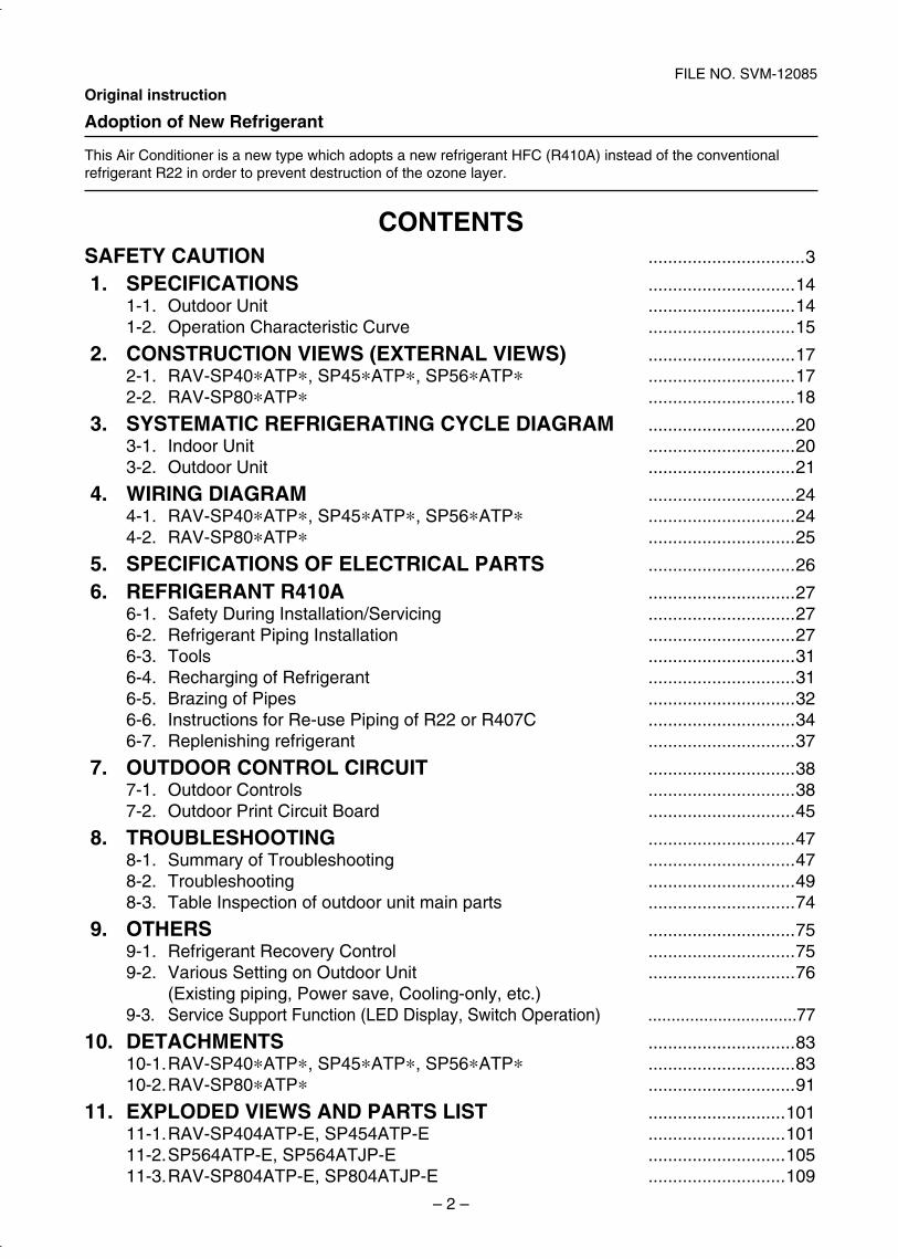
CONTENTSSAFETY CAUTION ................................3
1. SPECIFICATIONS ..............................141-1. Outdoor Unit ..............................141-2. Operation Characteristic Curve ..............................15
2. CONSTRUCTION VIEWS (EXTERNAL VIEWS) ..............................172-1. RAV-SP40*ATP*, SP45*ATP*, SP56*ATP* ..............................172-2. RAV-SP80*ATP* ..............................18
3. SYSTEMATIC REFRIGERATING CYCLE DIAGRAM ..............................203-1. Indoor Unit ..............................203-2. Outdoor Unit ..............................21
4. WIRING DIAGRAM ..............................244-1. RAV-SP40*ATP*, SP45*ATP*, SP56*ATP* ..............................244-2. RAV-SP80*ATP* ..............................25
5. SPECIFICATIONS OF ELECTRICAL PARTS ..............................26
6. REFRIGERANT R410A ..............................276-1. Safety During Installation/Servicing ..............................276-2. Refrigerant Piping Installation ..............................276-3. Tools ..............................316-4. Recharging of Refrigerant ..............................316-5. Brazing of Pipes ..............................326-6. Instructions for Re-use Piping of R22 or R407C ..............................346-7. Replenishing refrigerant ..............................37
7. OUTDOOR CONTROL CIRCUIT ..............................387-1. Outdoor Controls ..............................387-2. Outdoor Print Circuit Board ..............................45
8. TROUBLESHOOTING ..............................478-1. Summary of Troubleshooting ..............................478-2. Troubleshooting ..............................498-3. Table Inspection of outdoor unit main parts ..............................74
9. OTHERS ..............................759-1. Refrigerant Recovery Control ..............................759-2. Various Setting on Outdoor Unit ..............................76 (Existing piping, Power save, Cooling-only, etc.)9-3. Service Support Function (LED Display, Switch Operation) ................................77
10. DETACHMENTS ..............................8310-1. RAV-SP40*ATP*, SP45*ATP*, SP56*ATP* ..............................8310-2. RAV-SP80*ATP* ..............................91
11. EXPLODED VIEWS AND PARTS LIST ............................10111-1. RAV-SP404ATP-E, SP454ATP-E ............................10111-2. SP564ATP-E, SP564ATJP-E ............................10511-3. RAV-SP804ATP-E, SP804ATJP-E ............................109
SVM-12085_001-050.indd 2SVM-12085_001-050.indd 2 12/06/12 11:06 AM12/06/12 11:06 AM
– 3 –
FILE NO. SVM-12085
Please read carefully through these instructions that contain important information which complies with the“Machinery” Directive (Directive 2006/42/EC), and ensure that you understand them.
Generic Denomination: Air Conditioner
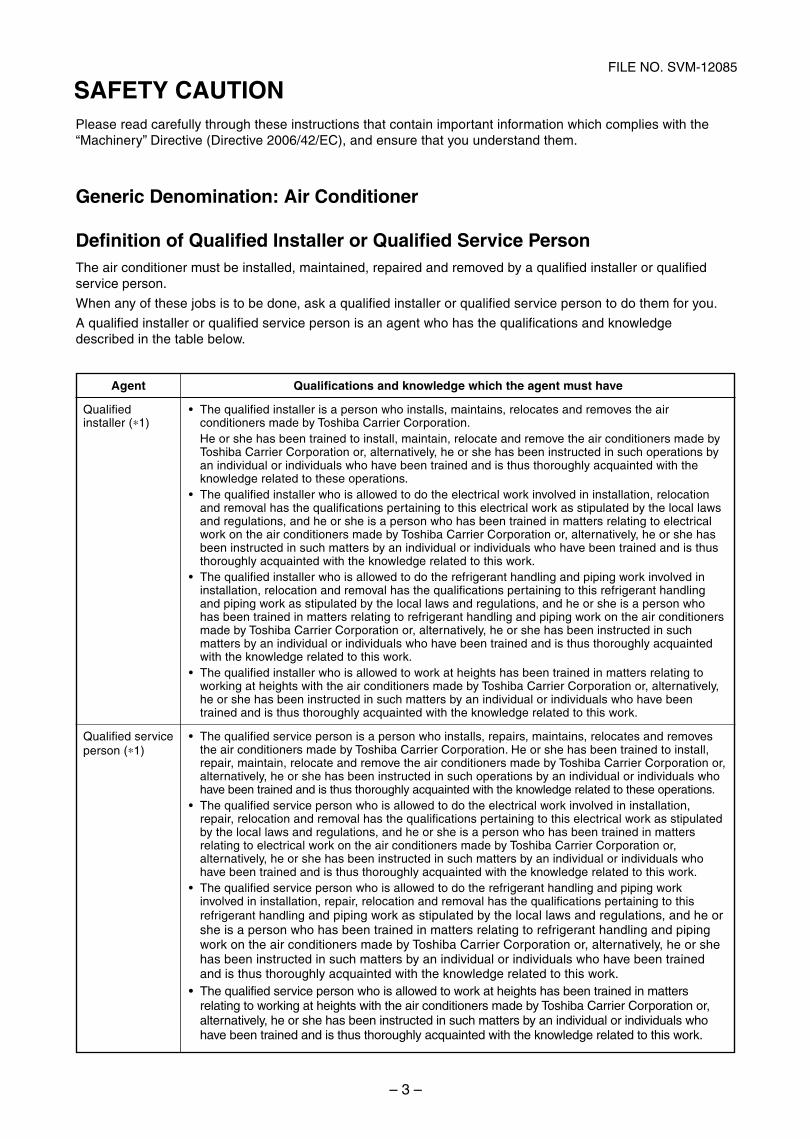
Definition of Qualified Installer or Qualified Service PersonThe air conditioner must be installed, maintained, repaired and removed by a qualified installer or qualifiedservice person.
When any of these jobs is to be done, ask a qualified installer or qualified service person to do them for you.
A qualified installer or qualified service person is an agent who has the qualifications and knowledgedescribed in the table below.
Agent
Qualifiedinstaller (∗1)
Qualified serviceperson (∗1)
Qualifications and knowledge which the agent must have
The qualified installer is a person who installs, maintains, relocates and removes the airconditioners made by Toshiba Carrier Corporation.He or she has been trained to install, maintain, relocate and remove the air conditioners made byToshiba Carrier Corporation or, alternatively, he or she has been instructed in such operations byan individual or individuals who have been trained and is thus thoroughly acquainted with theknowledge related to these operations.The qualified installer who is allowed to do the electrical work involved in installation, relocationand removal has the qualifications pertaining to this electrical work as stipulated by the local lawsand regulations, and he or she is a person who has been trained in matters relating to electricalwork on the air conditioners made by Toshiba Carrier Corporation or, alternatively, he or she hasbeen instructed in such matters by an individual or individuals who have been trained and is thusthoroughly acquainted with the knowledge related to this work.The qualified installer who is allowed to do the refrigerant handling and piping work involved ininstallation, relocation and removal has the qualifications pertaining to this refrigerant handlingand piping work as stipulated by the local laws and regulations, and he or she is a person whohas been trained in matters relating to refrigerant handling and piping work on the air conditionersmade by Toshiba Carrier Corporation or, alternatively, he or she has been instructed in suchmatters by an individual or individuals who have been trained and is thus thoroughly acquaintedwith the knowledge related to this work.The qualified installer who is allowed to work at heights has been trained in matters relating toworking at heights with the air conditioners made by Toshiba Carrier Corporation or, alternatively,he or she has been instructed in such matters by an individual or individuals who have beentrained and is thus thoroughly acquainted with the knowledge related to this work.
The qualified service person is a person who installs, repairs, maintains, relocates and removesthe air conditioners made by Toshiba Carrier Corporation. He or she has been trained to install,repair, maintain, relocate and remove the air conditioners made by Toshiba Carrier Corporation or,alternatively, he or she has been instructed in such operations by an individual or individuals whohave been trained and is thus thoroughly acquainted with the knowledge related to these operations.The qualified service person who is allowed to do the electrical work involved in installation,repair, relocation and removal has the qualifications pertaining to this electrical work as stipulatedby the local laws and regulations, and he or she is a person who has been trained in mattersrelating to electrical work on the air conditioners made by Toshiba Carrier Corporation or,alternatively, he or she has been instructed in such matters by an individual or individuals whohave been trained and is thus thoroughly acquainted with the knowledge related to this work.The qualified service person who is allowed to do the refrigerant handling and piping workinvolved in installation, repair, relocation and removal has the qualifications pertaining to thisrefrigerant handling and piping work as stipulated by the local laws and regulations, and he orshe is a person who has been trained in matters relating to refrigerant handling and pipingwork on the air conditioners made by Toshiba Carrier Corporation or, alternatively, he or shehas been instructed in such matters by an individual or individuals who have been trainedand is thus thoroughly acquainted with the knowledge related to this work.The qualified service person who is allowed to work at heights has been trained in mattersrelating to working at heights with the air conditioners made by Toshiba Carrier Corporation or,alternatively, he or she has been instructed in such matters by an individual or individuals whohave been trained and is thus thoroughly acquainted with the knowledge related to this work.
SAFETY CAUTION
SVM-12085_001-050.indd 3SVM-12085_001-050.indd 3 12/06/12 11:06 AM12/06/12 11:06 AM
– 4 –
FILE NO. SVM-12085
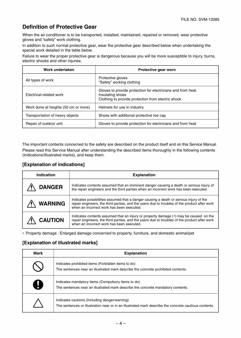
Definition of Protective GearWhen the air conditioner is to be transported, installed, maintained, repaired or removed, wear protectivegloves and “safety” work clothing.
In addition to such normal protective gear, wear the protective gear described below when undertaking thespecial work detailed in the table below.
Failure to wear the proper protective gear is dangerous because you will be more susceptible to injury, burns,electric shocks and other injuries.
Work undertaken
All types of work
Electrical-related work
Work done at heights (50 cm or more)
Transportation of heavy objects
Repair of outdoor unit
Protective gear worn
Protective gloves“Safety” working clothing
Gloves to provide protection for electricians and from heatInsulating shoesClothing to provide protection from electric shock
Helmets for use in industry
Shoes with additional protective toe cap
Gloves to provide protection for electricians and from heat
The important contents concerned to the safety are described on the product itself and on this Service Manual.
Please read this Service Manual after understanding the described items thoroughly in the following contents(Indications/Illustrated marks), and keep them.
[Explanation of indications]
Indication
DANGER
WARNING
CAUTION
Explanation
Indicates contents assumed that an imminent danger causing a death or serious injury ofthe repair engineers and the third parties when an incorrect work has been executed.
Indicates possibilities assumed that a danger causing a death or serious injury of therepair engineers, the third parties, and the users due to troubles of the product after workwhen an incorrect work has been executed.
Indicates contents assumed that an injury or property damage (∗) may be caused on therepair engineers, the third parties, and the users due to troubles of the product after workwhen an incorrect work has been executed.
∗ Property damage : Enlarged damage concerned to property, furniture, and domestic animal/pet
[Explanation of illustrated marks]
Mark Explanation
Indicates prohibited items (Forbidden items to do)
The sentences near an illustrated mark describe the concrete prohibited contents.
Indicates mandatory items (Compulsory items to do)
The sentences near an illustrated mark describe the concrete mandatory contents.
Indicates cautions (Including danger/warning)
The sentences or illustration near or in an illustrated mark describe the concrete cautious contents.
SVM-12085_001-050.indd 4SVM-12085_001-050.indd 4 12/06/12 11:06 AM12/06/12 11:06 AM
– 5 –
FILE NO. SVM-12085
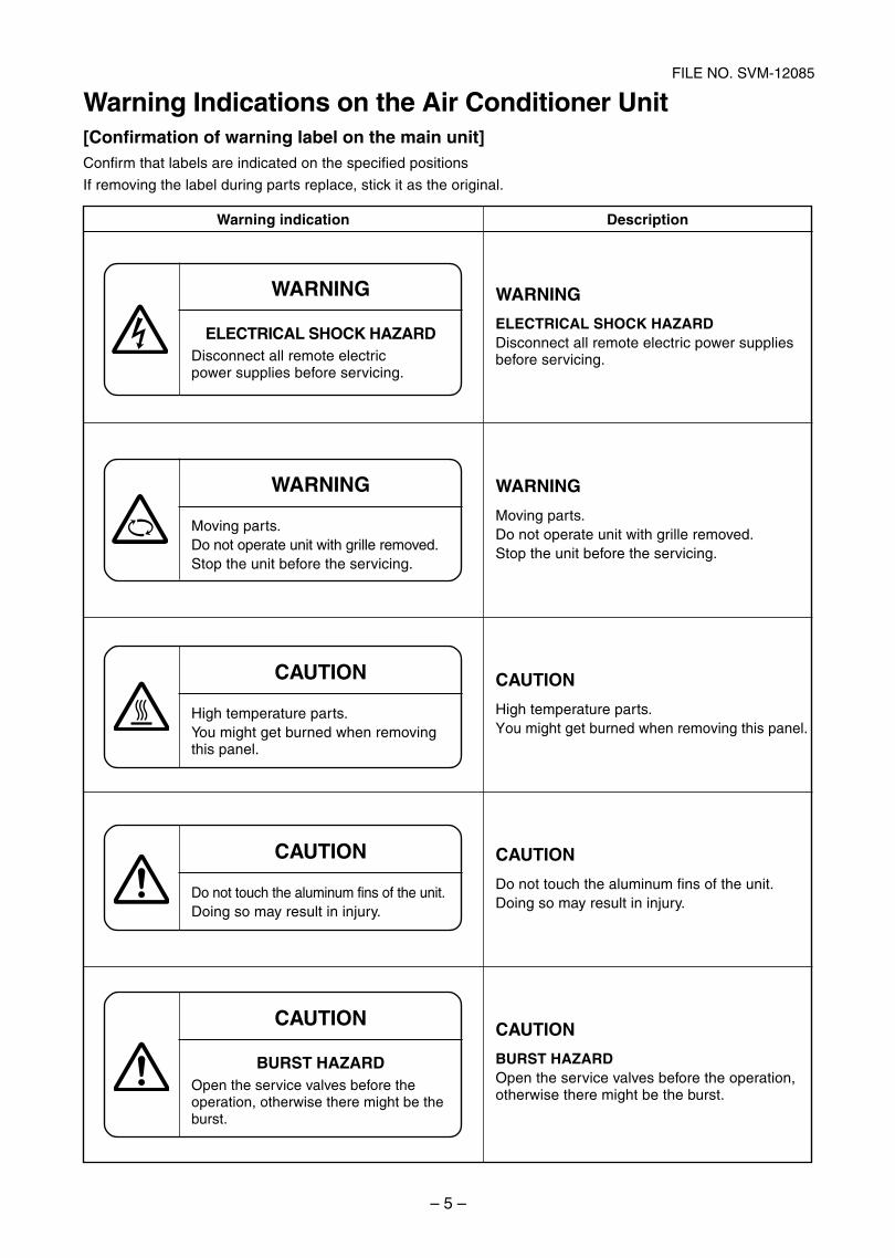
Warning Indications on the Air Conditioner Unit[Confirmation of warning label on the main unit]Confirm that labels are indicated on the specified positions
If removing the label during parts replace, stick it as the original.
Warning indication
WARNING
ELECTRICAL SHOCK HAZARDDisconnect all remote electricpower supplies before servicing.
WARNING
Moving parts.Do not operate unit with grille removed.Stop the unit before the servicing.
CAUTION
High temperature parts.You might get burned when removingthis panel.
CAUTION
Do not touch the aluminum fins of the unit.Doing so may result in injury.
CAUTION
BURST HAZARDOpen the service valves before theoperation, otherwise there might be theburst.
Description
WARNING
ELECTRICAL SHOCK HAZARDDisconnect all remote electric power suppliesbefore servicing.
WARNING
Moving parts.Do not operate unit with grille removed.Stop the unit before the servicing.
CAUTION
High temperature parts.You might get burned when removing this panel.
CAUTION
Do not touch the aluminum fins of the unit.Doing so may result in injury.
CAUTION
BURST HAZARDOpen the service valves before the operation,otherwise there might be the burst.
SVM-12085_001-050.indd 5SVM-12085_001-050.indd 5 12/06/12 11:06 AM12/06/12 11:06 AM
– 6 –
FILE NO. SVM-12085
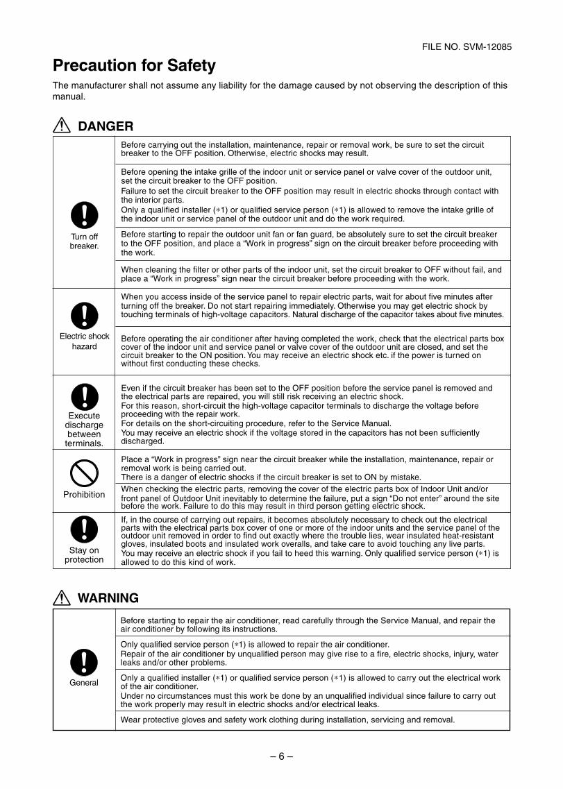
Before carrying out the installation, maintenance, repair or removal work, be sure to set the circuitbreaker to the OFF position. Otherwise, electric shocks may result.
Before opening the intake grille of the indoor unit or service panel or valve cover of the outdoor unit, set the circuit breaker to the OFF position.Failure to set the circuit breaker to the OFF position may result in electric shocks through contact withthe interior parts.Only a qualified installer ( 1) or qualified service person ( 1) is allowed to remove the intake grille ofthe indoor unit or service panel of the outdoor unit and do the work required.
Before starting to repair the outdoor unit fan or fan guard, be absolutely sure to set the circuit breakerto the OFF position, and place a “Work in progress” sign on the circuit breaker before proceeding withthe work.
When cleaning the filter or other parts of the indoor unit, set the circuit breaker to OFF without fail, andplace a “Work in progress” sign near the circuit breaker before proceeding with the work.
When you access inside of the service panel to repair electric parts, wait for about five minutes afterturning off the breaker. Do not start repairing immediately. Otherwise you may get electric shock bytouching terminals of high-voltage capacitors. Natural discharge of the capacitor takes about five minutes.
Before operating the air conditioner after having completed the work, check that the electrical parts boxcover of the indoor unit and service panel or valve cover of the outdoor unit are closed, and set the circuit breaker to the ON position. You may receive an electric shock etc. if the power is turned on without first conducting these checks.
Even if the circuit breaker has been set to the OFF position before the service panel is removed andthe electrical parts are repaired, you will still risk receiving an electric shock.For this reason, short-circuit the high-voltage capacitor terminals to discharge the voltage beforeproceeding with the repair work.For details on the short-circuiting procedure, refer to the Service Manual.You may receive an electric shock if the voltage stored in the capacitors has not been sufficientlydischarged.
Place a “Work in progress” sign near the circuit breaker while the installation, maintenance, repair orremoval work is being carried out.There is a danger of electric shocks if the circuit breaker is set to ON by mistake.When checking the electric parts, removing the cover of the electric parts box of Indoor Unit and/orfront panel of Outdoor Unit inevitably to determine the failure, put a sign “Do not enter” around the sitebefore the work. Failure to do this may result in third person getting electric shock.
If, in the course of carrying out repairs, it becomes absolutely necessary to check out the electricalparts with the electrical parts box cover of one or more of the indoor units and the service panel of theoutdoor unit removed in order to find out exactly where the trouble lies, wear insulated heat-resistantgloves, insulated boots and insulated work overalls, and take care to avoid touching any live parts.You may receive an electric shock if you fail to heed this warning. Only qualified service person ( 1) isallowed to do this kind of work.
Precaution for Safety
DANGER
Before starting to repair the air conditioner, read carefully through the Service Manual, and repair theair conditioner by following its instructions.
Only qualified service person ( 1) is allowed to repair the air conditioner.Repair of the air conditioner by unqualified person may give rise to a fire, electric shocks, injury, waterleaks and/or other problems.
Only a qualified installer ( 1) or qualified service person ( 1) is allowed to carry out the electrical workof the air conditioner.Under no circumstances must this work be done by an unqualified individual since failure to carry outthe work properly may result in electric shocks and/or electrical leaks.
Wear protective gloves and safety work clothing during installation, servicing and removal.
General
WARNING
The manufacturer shall not assume any liability for the damage caused by not observing the description of thismanual.
Turn offbreaker.
Electric shockhazard
Executedischargebetween
terminals.
Prohibition
Stay onprotection
SVM-12085_001-050.indd 6SVM-12085_001-050.indd 6 12/06/12 11:06 AM12/06/12 11:06 AM
– 7 –
FILE NO. SVM-12085
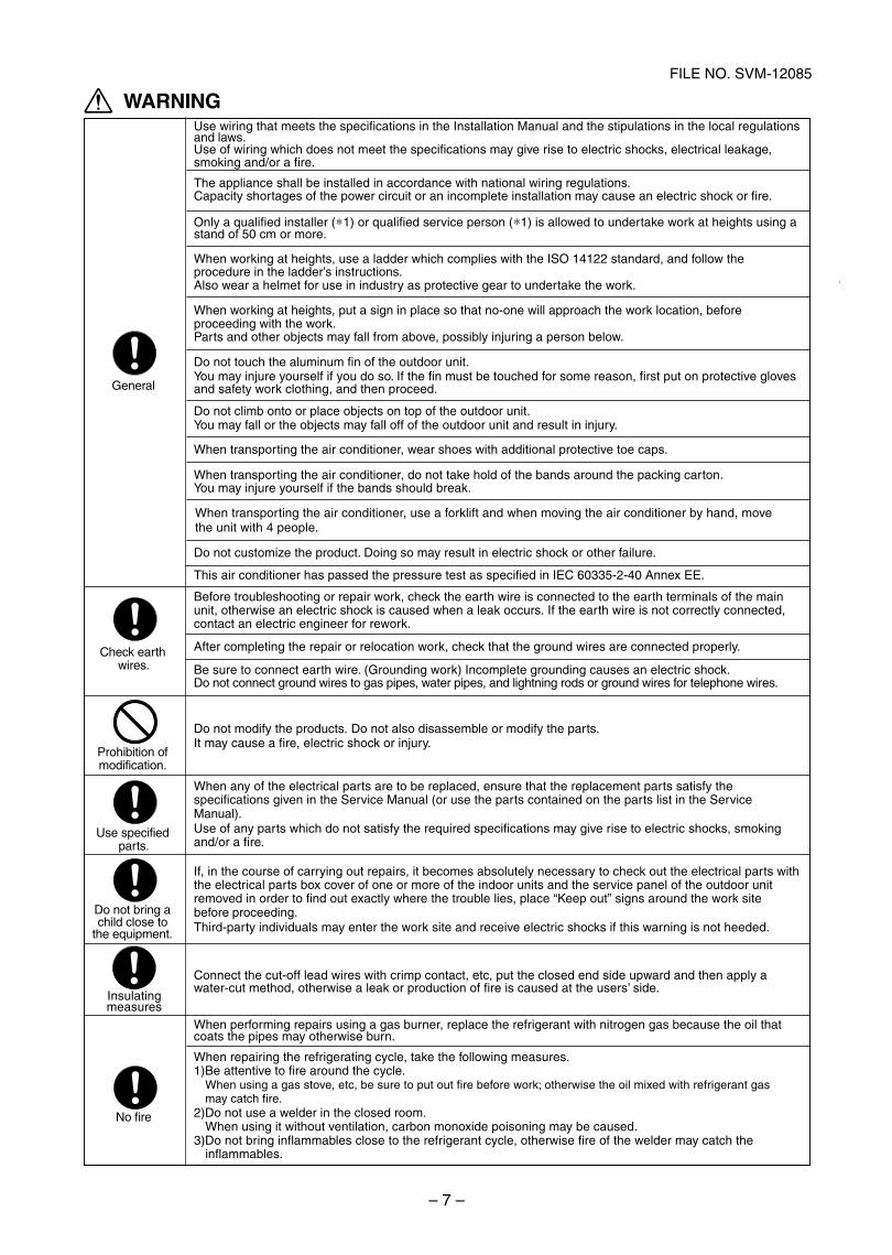
Do not customize the product. Doing so may result in electric shock or other failure.
This air conditioner has passed the pressure test as specified in IEC 60335-2-40 Annex EE.
Before troubleshooting or repair work, check the earth wire is connected to the earth terminals of the mainunit, otherwise an electric shock is caused when a leak occurs. If the earth wire is not correctly connected,contact an electric engineer for rework.
After completing the repair or relocation work, check that the ground wires are connected properly.
Be sure to connect earth wire. (Grounding work) Incomplete grounding causes an electric shock.Do not connect ground wires to gas pipes, water pipes, and lightning rods or ground wires for telephone wires.
Do not modify the products. Do not also disassemble or modify the parts.It may cause a fire, electric shock or injury.
When any of the electrical parts are to be replaced, ensure that the replacement parts satisfy thespecifications given in the Service Manual (or use the parts contained on the parts list in the ServiceManual).Use of any parts which do not satisfy the required specifications may give rise to electric shocks, smokingand/or a fire.
If, in the course of carrying out repairs, it becomes absolutely necessary to check out the electrical parts withthe electrical parts box cover of one or more of the indoor units and the service panel of the outdoor unitremoved in order to find out exactly where the trouble lies, place “Keep out” signs around the work sitebefore proceeding.Third-party individuals may enter the work site and receive electric shocks if this warning is not heeded.
Connect the cut-off lead wires with crimp contact, etc, put the closed end side upward and then apply awater-cut method, otherwise a leak or production of fire is caused at the users’ side.
When performing repairs using a gas burner, replace the refrigerant with nitrogen gas because the oil thatcoats the pipes may otherwise burn.
When repairing the refrigerating cycle, take the following measures.1)Be attentive to fire around the cycle. When using a gas stove, etc, be sure to put out fire before work; otherwise the oil mixed with refrigerant gas
may catch fire.2)Do not use a welder in the closed room.
When using it without ventilation, carbon monoxide poisoning may be caused.3)Do not bring inflammables close to the refrigerant cycle, otherwise fire of the welder may catch the
inflammables.
WARNING
General
Check earthwires.
Prohibition ofmodification.
Do not bring a child close to
the equipment.
Use specifiedparts.
Insulatingmeasures
No fire
Use wiring that meets the specifications in the Installation Manual and the stipulations in the local regulationsand laws.Use of wiring which does not meet the specifications may give rise to electric shocks, electrical leakage,smoking and/or a fire.
The appliance shall be installed in accordance with national wiring regulations.Capacity shortages of the power circuit or an incomplete installation may cause an electric shock or fire.
Only a qualified installer ( 1) or qualified service person ( 1) is allowed to undertake work at heights using astand of 50 cm or more.
When working at heights, use a ladder which complies with the ISO 14122 standard, and follow theprocedure in the ladder’s instructions.Also wear a helmet for use in industry as protective gear to undertake the work.
When working at heights, put a sign in place so that no-one will approach the work location, beforeproceeding with the work.Parts and other objects may fall from above, possibly injuring a person below.
Do not touch the aluminum fin of the outdoor unit.You may injure yourself if you do so. If the fin must be touched for some reason, first put on protective glovesand safety work clothing, and then proceed.
Do not climb onto or place objects on top of the outdoor unit.You may fall or the objects may fall off of the outdoor unit and result in injury.
When transporting the air conditioner, wear shoes with additional protective toe caps.
When transporting the air conditioner, do not take hold of the bands around the packing carton.You may injure yourself if the bands should break.
When transporting the air conditioner, use a forklift and when moving the air conditioner by hand, movethe unit with 4 people.
SVM-12085_001-050.indd 7SVM-12085_001-050.indd 7 12/06/12 11:06 AM12/06/12 11:06 AM
– 8 –
FILE NO. SVM-12085
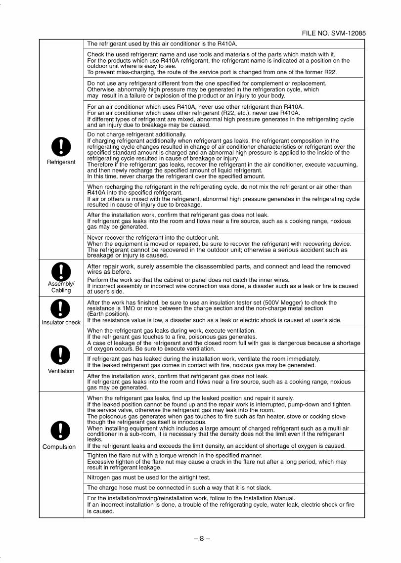
The refrigerant used by this air conditioner is the R410A.
Check the used refrigerant name and use tools and materials of the parts which match with it.For the products which use R410A refrigerant, the refrigerant name is indicated at a position on theoutdoor unit where is easy to see.To prevent miss-charging, the route of the service port is changed from one of the former R22.
Do not use any refrigerant different from the one specified for complement or replacement.Otherwise, abnormally high pressure may be generated in the refrigeration cycle, whichmay result in a failure or explosion of the product or an injury to your body.
For an air conditioner which uses R410A, never use other refrigerant than R410A.For an air conditioner which uses other refrigerant (R22, etc.), never use R410A.If different types of refrigerant are mixed, abnormal high pressure generates in the refrigerating cycleand an injury due to breakage may be caused.
Do not charge refrigerant additionally.If charging refrigerant additionally when refrigerant gas leaks, the refrigerant composition in therefrigerating cycle changes resulted in change of air conditioner characteristics or refrigerant over thespecified standard amount is charged and an abnormal high pressure is applied to the inside of therefrigerating cycle resulted in cause of breakage or injury.Therefore if the refrigerant gas leaks, recover the refrigerant in the air conditioner, execute vacuuming,and then newly recharge the specified amount of liquid refrigerant.In this time, never charge the refrigerant over the specified amount.
When recharging the refrigerant in the refrigerating cycle, do not mix the refrigerant or air other thanR410A into the specified refrigerant.If air or others is mixed with the refrigerant, abnormal high pressure generates in the refrigerating cycleresulted in cause of injury due to breakage.
After the installation work, confirm that refrigerant gas does not leak.If refrigerant gas leaks into the room and flows near a fire source, such as a cooking range, noxious gas may be generated.
Never recover the refrigerant into the outdoor unit.When the equipment is moved or repaired, be sure to recover the refrigerant with recovering device.The refrigerant cannot be recovered in the outdoor unit; otherwise a serious accident such asbreakage or injury is caused.
After repair work, surely assemble the disassembled parts, and connect and lead the removedwires as before.Perform the work so that the cabinet or panel does not catch the inner wires.If incorrect assembly or incorrect wire connection was done, a disaster such as a leak or fire is causedat user’s side.
After the work has finished, be sure to use an insulation tester set (500V Megger) to check theresistance is 1MΩ or more between the charge section and the non-charge metal section(Earth position).If the resistance value is low, a disaster such as a leak or electric shock is caused at user’s side.
When the refrigerant gas leaks during work, execute ventilation.If the refrigerant gas touches to a fire, poisonous gas generates.A case of leakage of the refrigerant and the closed room full with gas is dangerous because a shortageof oxygen occurs. Be sure to execute ventilation.
If refrigerant gas has leaked during the installation work, ventilate the room immediately.If the leaked refrigerant gas comes in contact with fire, noxious gas may be generated.
After the installation work, confirm that refrigerant gas does not leak.If refrigerant gas leaks into the room and flows near a fire source, such as a cooking range, noxious gas may be generated.
When the refrigerant gas leaks, find up the leaked position and repair it surely.If the leaked position cannot be found up and the repair work is interrupted, pump-down and tightenthe service valve, otherwise the refrigerant gas may leak into the room.The poisonous gas generates when gas touches to fire such as fan heater, stove or cocking stovethough the refrigerant gas itself is innocuous.When installing equipment which includes a large amount of charged refrigerant such as a multi airconditioner in a sub-room, it is necessary that the density does not the limit even if the refrigerantleaks.If the refrigerant leaks and exceeds the limit density, an accident of shortage of oxygen is caused.
Tighten the flare nut with a torque wrench in the specified manner.Excessive tighten of the flare nut may cause a crack in the flare nut after a long period, which mayresult in refrigerant leakage.
Nitrogen gas must be used for the airtight test.
The charge hose must be connected in such a way that it is not slack.
For the installation/moving/reinstallation work, follow to the Installation Manual.If an incorrect installation is done, a trouble of the refrigerating cycle, water leak, electric shock or fireis caused.
Refrigerant
Assembly/Cabling
Insulator check
Ventilation
Compulsion
SVM-12085_001-050.indd 8SVM-12085_001-050.indd 8 12/06/12 11:06 AM12/06/12 11:06 AM
– 9 –
FILE NO. SVM-12085
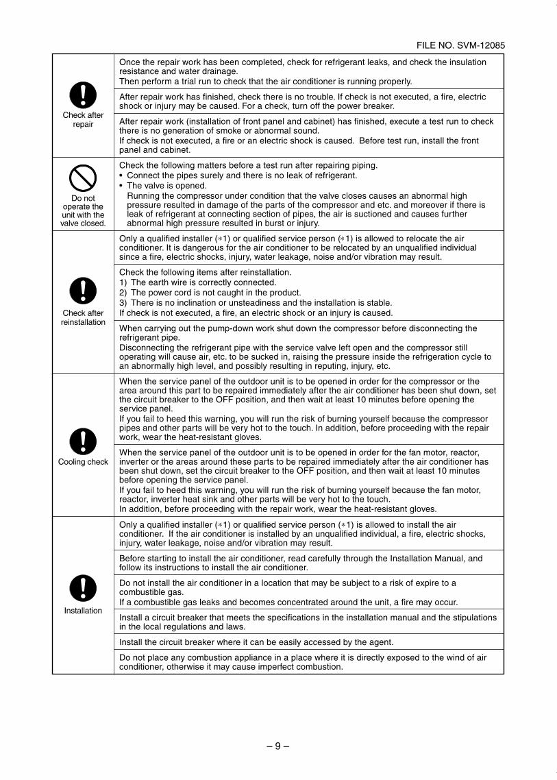
Check afterrepair
Do notoperate theunit with thevalve closed.
Check afterreinstallation
Cooling check
Installation
Once the repair work has been completed, check for refrigerant leaks, and check the insulationresistance and water drainage.Then perform a trial run to check that the air conditioner is running properly.
After repair work has finished, check there is no trouble. If check is not executed, a fire, electricshock or injury may be caused. For a check, turn off the power breaker.
After repair work (installation of front panel and cabinet) has finished, execute a test run to checkthere is no generation of smoke or abnormal sound.If check is not executed, a fire or an electric shock is caused. Before test run, install the frontpanel and cabinet.
Check the following matters before a test run after repairing piping.Connect the pipes surely and there is no leak of refrigerant.The valve is opened.Running the compressor under condition that the valve closes causes an abnormal highpressure resulted in damage of the parts of the compressor and etc. and moreover if there isleak of refrigerant at connecting section of pipes, the air is suctioned and causes furtherabnormal high pressure resulted in burst or injury.
Only a qualified installer ( 1) or qualified service person ( 1) is allowed to relocate the airconditioner. It is dangerous for the air conditioner to be relocated by an unqualified individualsince a fire, electric shocks, injury, water leakage, noise and/or vibration may result.
Check the following items after reinstallation.1) The earth wire is correctly connected.2) The power cord is not caught in the product.3) There is no inclination or unsteadiness and the installation is stable.If check is not executed, a fire, an electric shock or an injury is caused.
When carrying out the pump-down work shut down the compressor before disconnecting therefrigerant pipe.Disconnecting the refrigerant pipe with the service valve left open and the compressor stilloperating will cause air, etc. to be sucked in, raising the pressure inside the refrigeration cycle toan abnormally high level, and possibly resulting in reputing, injury, etc.
When the service panel of the outdoor unit is to be opened in order for the compressor or thearea around this part to be repaired immediately after the air conditioner has been shut down, setthe circuit breaker to the OFF position, and then wait at least 10 minutes before opening theservice panel.If you fail to heed this warning, you will run the risk of burning yourself because the compressorpipes and other parts will be very hot to the touch. In addition, before proceeding with the repairwork, wear the heat-resistant gloves.
When the service panel of the outdoor unit is to be opened in order for the fan motor, reactor,inverter or the areas around these parts to be repaired immediately after the air conditioner hasbeen shut down, set the circuit breaker to the OFF position, and then wait at least 10 minutesbefore opening the service panel.If you fail to heed this warning, you will run the risk of burning yourself because the fan motor,reactor, inverter heat sink and other parts will be very hot to the touch.In addition, before proceeding with the repair work, wear the heat-resistant gloves.
Only a qualified installer ( 1) or qualified service person ( 1) is allowed to install the airconditioner. If the air conditioner is installed by an unqualified individual, a fire, electric shocks,injury, water leakage, noise and/or vibration may result.
Before starting to install the air conditioner, read carefully through the Installation Manual, andfollow its instructions to install the air conditioner.
Do not install the air conditioner in a location that may be subject to a risk of expire to acombustible gas.If a combustible gas leaks and becomes concentrated around the unit, a fire may occur.
Install a circuit breaker that meets the specifications in the installation manual and the stipulationsin the local regulations and laws.
Install the circuit breaker where it can be easily accessed by the agent.
Do not place any combustion appliance in a place where it is directly exposed to the wind of airconditioner, otherwise it may cause imperfect combustion.
SVM-12085_001-050.indd 9SVM-12085_001-050.indd 9 12/06/12 11:06 AM12/06/12 11:06 AM
– 10 –
FILE NO. SVM-12085
Explanations given to userIf you have discovered that the fan grille is damaged, do not approach the outdoor unit but set the circuit breakerto the OFF position, and contact a qualified service person to have the repairs done.Do not set the circuit breaker to the ON position until the repairs are completed.
RelocationOnly a qualified installer ( 1) or qualified service person ( 1) is allowed to relocate the air conditioner.It is dangerous for the air conditioner to be relocated by an unqualified individual since a fire, electric shocks,injury, water leakage, noise and/or vibration may result.When carrying out the pump-down work shut down the compressor before disconnecting the refrigerant pipe.Disconnecting the refrigerant pipe with the service valve left open and the compressor still operating will cause air,etc. to be sucked in, raising the pressure inside the refrigeration cycle to an abnormally high level, and possiblyresulting in reputing, injury, etc.
( 1) Refer to the “Definition of Qualified Installer or Qualified Service Person.”
Declaration of ConformityTOSHIBA CARRIER (THAILAND) CO., LTD.144 / 9 Moo 5, Bangkadi Industrial Park, Tivanon Road,Amphur Muang, Pathumthani 12000, Thailand
RAV-SP404ATP-E RAV-SP454ATP-E RAV-SP564ATP-ERAV-SP564ATJP-E RAV-SP804ATP-E RAV-SP804ATJP-E
Manufacturer:
Nick BallRepresentative/TCF holder: Toshiba EMEA Engineering Director
Toshiba Carrier UK Ltd.Porsham Close, Belliver Industrial Estate,PLYMOUTH, Devon, PL6 7DB.United Kingdom
Authorized
Hereby declares that the machinery described below:Generic Denomination: Air ConditionerModel/type:
Commercial name: Super Digital Inverter Series Air ConditionerComplies with the provisions of the “Machinery” Directive (Directive 2006/42/EC) and the regulations transposinginto national law.Complies with the provisions of the following harmonized standard:
EN 378-2: 2008 + A2:2012Note: This declaration becomes invalid if technical or operational modifications are introduced without the
manufacturer’s consent.
DisposalHow to dispose of air conditioners with a rating of 12 kW and below in accordance with the 2002/96/EC DirectiveWEEE (Waste Electrical and Electronic Equipment) is provided in the Installation Manual supplied with your product.For disposal of the product above 12 kW in rating you should use a registered company in accordance with anynational or EU legislation.
<Model names with a rating of 12 kW and below (outdoor units)>
SDI seriesRAV-SP404ATP-E RAV-SP454ATP-E RAV-SP564ATP-ERAV-SP564ATJP-E RAV-SP804ATP-E RAV-SP804ATJP-E
SVM-12085_001-050.indd 10SVM-12085_001-050.indd 10 12/06/12 11:06 AM12/06/12 11:06 AM
– 11 –
FILE NO. SVM-12085
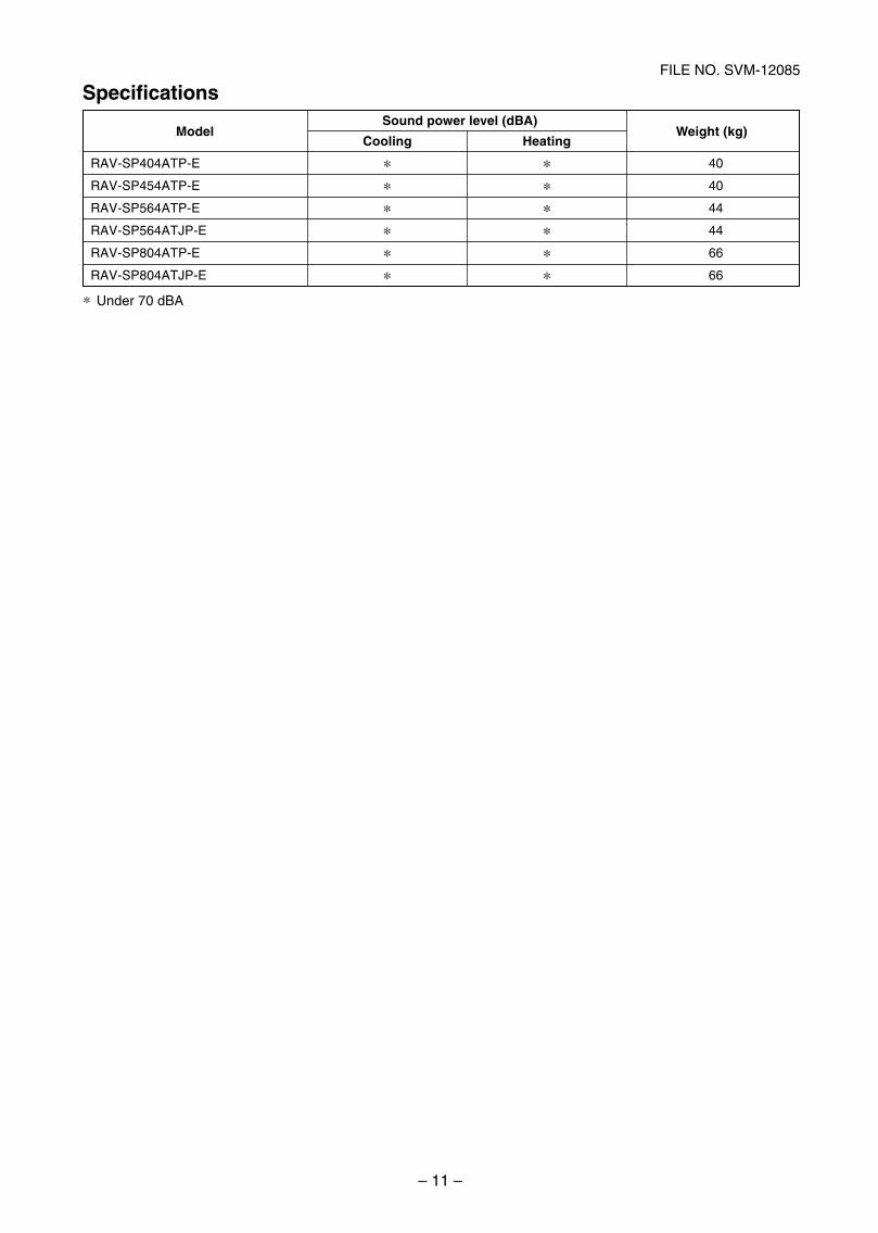
Specifications
ModelSound power level (dBA)
Cooling HeatingWeight (kg)
RAV-SP404ATP-E
RAV-SP454ATP-E
RAV-SP564ATP-E
RAV-SP564ATJP-E
RAV-SP804ATP-E
RAV-SP804ATJP-E
40
40
44
44
66
66
Under 70 dBA
SVM-12085_001-050.indd 11SVM-12085_001-050.indd 11 12/06/12 11:06 AM12/06/12 11:06 AM
– 12 –
FILE NO. SVM-12085
New Refrigerant (R410A)This air conditioner adopts a new HFC type refrigerant (R410A) which does not deplete the ozone layer.
1. Safety Caution Concerned to New Refrigerant
The pressure of R410A is high 1.6 times of that of the former refrigerant (R22).
Accompanied with change of refrigerant, the refrigerating oil has been also changed.
Therefore, be sure that water, dust, the former refrigerant or the former refrigerating oil is not mixed into therefrigerating cycle of the air conditioner with new refrigerant during installation work or service work.
If an incorrect work or incorrect service is performed, there is a possibility to cause a serious accident.
Use the tools and materials exclusive to R410A to purpose a safe work.
2. Cautions on Installation/Service
1) Do not mix the other refrigerant or refrigerating oil.
For the tools exclusive to R410A, shapes of all the joints including the service port differ from those ofthe former refrigerant in order to prevent mixture of them.
2) As the use pressure of the new refrigerant is high, use material thickness of the pipe and tools which arespecified for R410A.
3) In the installation time, use clean pipe materials and work with great attention so that water and others donot mix in because pipes are affected by impurities such as water, oxide scales, oil, etc.
Use the clean pipes.
Be sure to brazing with flowing nitrogen gas. (Never use gas other than nitrogen gas.)
4) For the earth protection, use a vacuum pump for air purge.
5) R410A refrigerant is azeotropic mixture type refrigerant.
Therefore use liquid type to charge the refrigerant. (If using gas for charging, composition of therefrigerant changes and then characteristics of the air conditioner change.)
3. Pipe Materials
For the refrigerant pipes, copper pipe and joints are mainly used.
It is necessary to select the most appropriate pipes to conform to the standard.
Use clean material in which impurities adhere inside of pipe or joint to a minimum.
1) Copper pipe
<Piping>The pipe thickness, flare finishing size, flare nut and others differ according to a refrigerant type.
When using a long copper pipe for R410A, it is recommended to select “Copper or copper-base pipewithout seam” and one with bonded oil amount 40mg/10m or less.
Also do not use crushed, deformed, discolored (especially inside) pipes.(Impurities cause clogging of expansion valves and capillary tubes.)
<Flare nut>Use the flare nuts which are attached to the air conditioner unit.
2) JointThe flare joint and socket joint are used for joints of the copper pipe.
The joints are rarely used for installation of the air conditioner. However clear impurities when using them.
SVM-12085_001-050.indd 12SVM-12085_001-050.indd 12 12/06/12 11:06 AM12/06/12 11:06 AM
– 13 –
FILE NO. SVM-12085
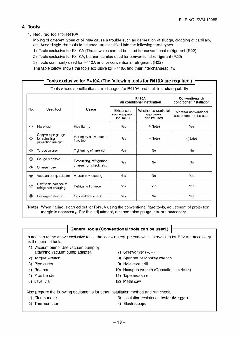
4. Tools
1. Required Tools for R410A
Mixing of different types of oil may cause a trouble such as generation of sludge, clogging of capillary,etc. Accordingly, the tools to be used are classified into the following three types.
1) Tools exclusive for R410A (Those which cannot be used for conventional refrigerant (R22))
2) Tools exclusive for R410A, but can be also used for conventional refrigerant (R22)
3) Tools commonly used for R410A and for conventional refrigerant (R22)
The table below shows the tools exclusive for R410A and their interchangeability.
Tools exclusive for R410A (The following tools for R410A are required.)
Tools whose specifications are changed for R410A and their interchangeability
(Note) When flaring is carried out for R410A using the conventional flare tools, adjustment of projectionmargin is necessary. For this adjustment, a copper pipe gauge, etc. are necessary.
General tools (Conventional tools can be used.)
In addition to the above exclusive tools, the following equipments which serve also for R22 are necessaryas the general tools.
1) Vacuum pump. Use vacuum pump byattaching vacuum pump adapter. 7) Screwdriver (+, –)
hcnerw yeknoM ro rennapS)8hcnerw euqroT)2
llird eroc eloH)9rettuc epiP)3
)mm4 edis etisoppO( hcnerw nogaxeH)01remaeR)4
erusaem epaT)11redneb epiP)5
was lateM)21laiv leveL)6
Also prepare the following equipments for other installation method and run check.
)reggeM( retset ecnatsiser noitalusnI)3retem pmalC)1
epocsortcelE)4retemomrehT)2
No. Used tool
Flare tool
Copper pipe gaugefor adjustingprojection margin
Torque wrench
Gauge manifold
Charge hose
Vacuum pump adapter
Electronic balance forrefrigerant charging
Leakage detector
Usage
Pipe flaring
Flaring by conventionalflare tool
Tightening of flare nut
Evacuating, refrigerantcharge, run check, etc.
Vacuum evacuating
Refrigerant charge
Gas leakage check
R410Aair conditioner installation
Existence of Whether conventionalnew equipment equipment
for R410A can be used
Yes (Note)
Yes (Note)
Yes No
Yes No
Yes No
Yes Yes
Yes No
Conventional airconditioner installation
Whether conventionalequipment can be used
Yes
(Note)
No
No
Yes
Yes
Yes
SVM-12085_001-050.indd 13SVM-12085_001-050.indd 13 12/06/12 11:06 AM12/06/12 11:06 AM
– 14 –
FILE NO. SVM-12085-1
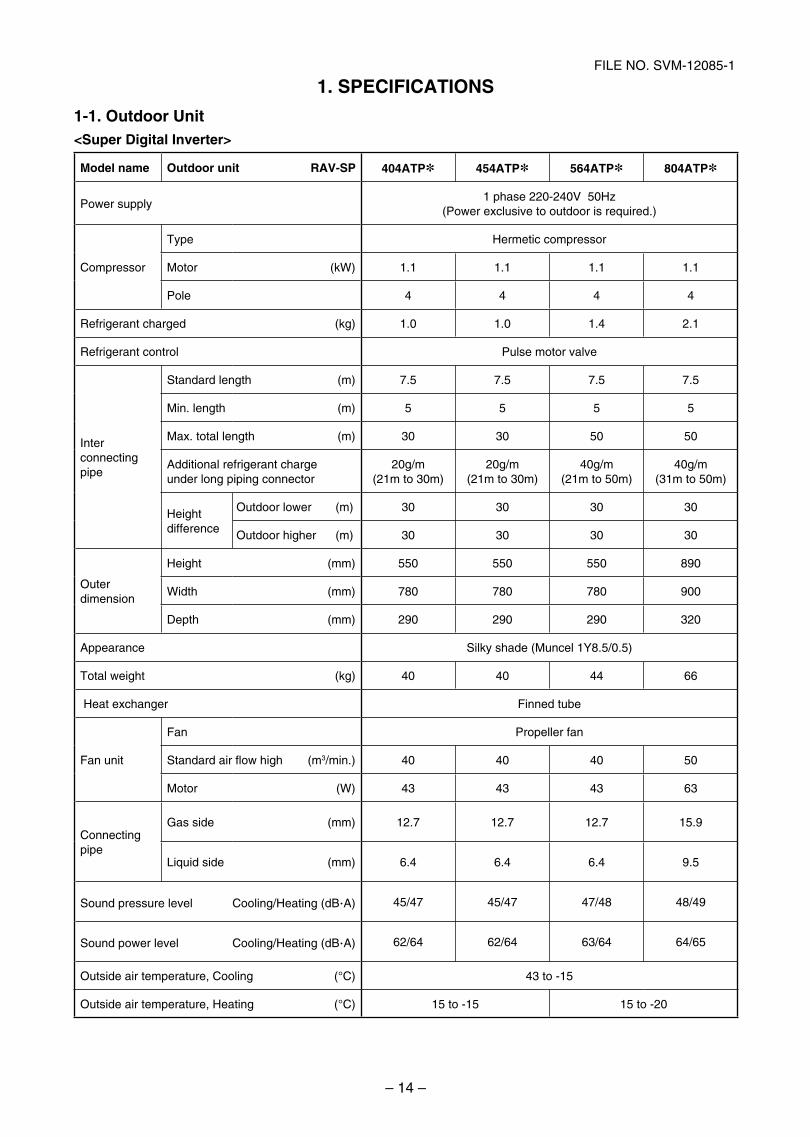
1. SPECIFICATIONS
1-1. Outdoor Unit<Super Digital Inverter>
Model name Outdoor unit RAV-SP 404ATP* 454ATP* 564ATP* 804ATP*
Power supply1 phase 220-240V 50Hz
(Power exclusive to outdoor is required.)
Compressor
Type Hermetic compressor
Motor (kW) 1.1 1.1 1.1 1.1
Pole 4 4 4 4
Refrigerant charged (kg) 1.0 1.0 1.4 2.1
Refrigerant control Pulse motor valve
Interconnecting pipe
Standard length (m) 7.5 7.5 7.5 7.5
Min. length (m) 5 5 5 5
Max. total length (m) 30 30 50 50
Additional refrigerant chargeunder long piping connector
20g/m(21m to 30m)
20g/m(21m to 30m)
40g/m(21m to 50m)
40g/m(31m to 50m)
Heightdifference
Outdoor lower (m) 30 30 30 30
Outdoor higher (m) 30 30 30 30
Outer dimension
Height (mm) 550 550 550 890
Width (mm) 780 780 780 900
Depth (mm) 290 290 290 320
Appearance Silky shade (Muncel 1Y8.5/0.5)
Total weight (kg) 40 40 44 66
Heat exchanger Finned tube
Fan unit
Fan Propeller fan
Standard air flow high (m3/min.) 40 40 40 50
Motor (W) 43 43 43 63
Connecting pipe
Gas side (mm) 12.7 12.7 12.7 15.9
Liquid side (mm) 6.4 6.4 6.4 9.5
Sound pressure level Cooling/Heating (dB·A) 45/47 45/47 47/48 48/49
Sound power level Cooling/Heating (dB·A) 62/64 62/64 63/64 64/65
Outside air temperature, Cooling (°C) 43 to -15
Outside air temperature, Heating (°C) 15 to -15 15 to -20
SVM-12085_001-050.indd 14SVM-12085_001-050.indd 14 12/06/12 11:06 AM12/06/12 11:06 AM
– 15 –
FILE NO. SVM-12085
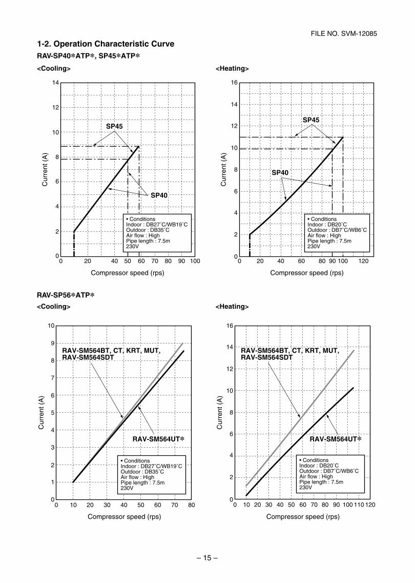
RAV-SP40 ATP , SP45 ATP
>gnitaeH<>gnilooC<
00 20 40 50 60 70 80 90 100
2
4
6
8
10
12
14
Compressor speed (rps)
Cur
rent
(A
)
00 20 40 60 80 90 100 120
2
4
6
8
10
12
16
14
Compressor speed (rps)
Cur
rent
(A
) Conditions
Indoor : DB27˚C/WB19˚COutdoor : DB35˚CAir flow : HighPipe length : 7.5m230V
ConditionsIndoor : DB20˚COutdoor : DB7˚C/WB6˚CAir flow : HighPipe length : 7.5m230V
SP40
SP40
SP45SP45
SP40
SP40
SP45SP45
RAV-SP56 ATP
>gnitaeH<>gnilooC<
Compressor speed (rps)
0 2010 30 40 50 60 70 800
10
9
8
7
6
5
3
4
2
1
Cur
rent
(A
)
Cur
rent
(A
)
0
16
14
12
8
10
6
4
2
0 20 3010 40 50 60 70 80 90 100 110 120
Compressor speed (rps)
Indoor : DB27˚C/WB19˚COutdoor : DB35˚CAir flow : HighPipe length : 7.5m230V
Indoor : DB20˚COutdoor : DB7˚C/WB6˚CAir flow : HighPipe length : 7.5m230V
RAV-SM562BT, CT, KRT, MUT-E, RAV-SM564SDT-E
RAV-SM562BT, CT, KRT, MUT-E, RAV-SM564SDT-E
RAV-SM564UT-ERAV-SM564UT-E
RAV-SM564BT, CT, KRT, MUT, RAV-SM564SDT
RAV-SM564BT, CT, KRT, MUT, RAV-SM564SDT
RAV-SM564UTRAV-SM564UT
1-2. Operation Characteristic Curve
SVM-12085_001-050.indd 15SVM-12085_001-050.indd 15 12/06/12 11:06 AM12/06/12 11:06 AM
– 16 –
FILE NO. SVM-12085
>gnitaeH<>gnilooC<
0 2010 30 40 50 60 70 800
13
12
11
10
9
8
7
6
5
3
4
2
1
0
16
18
20
22
14
12
8
10
6
4
2
0 20 30 40 50 60 70 80 90 100 110 12010
Compressor speed (rps)
Cur
rent
(A
)
Cur
rent
(A
)
Compressor speed (rps)
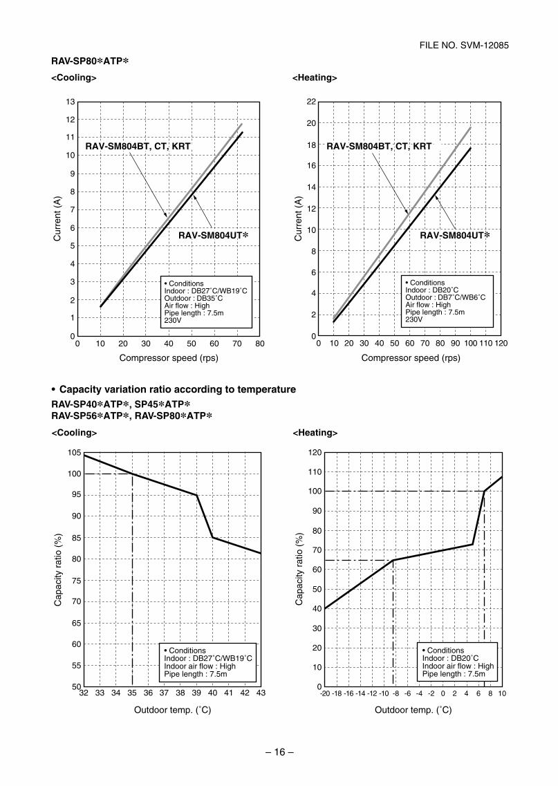
Indoor : DB27˚C/WB19˚COutdoor : DB35˚C
230V
Indoor : DB20˚COutdoor : DB7˚C/WB6˚C
230V
RAV-SM802BT, CT, KRT-E RAV-SM802BT, CT, KRT-E
RAV-SM804UT-E RAV-SM804UT-E
TRK ,TC ,TB408MS-VARTRK ,TC ,TB408MS-VAR
TU408MS-VARTU408MS-VAR
RAV-SP80 ATP
50
55
60
65
70
75
80
85
90
95
100
105
32 33 34 35 36 37 38 39 40 41 42 43
˚C)
0
10
20
30
40
50
60
70
80
90
100
110
120
-14-16-18-20 -12 -10 -8 -6 -4 -2 0 2 4 6 8 10
˚C)
Indoor : DB20˚CIndoor : DB27˚C/WB19˚C
Capacity variation ratio according to temperature
>gnitaeH<>gnilooC<
RAV-SP40 ATP , SP45 ATPRAV-SP56 ATP , RAV-SP80 ATP
SVM-12085_001-050.indd 16SVM-12085_001-050.indd 16 12/06/12 11:06 AM12/06/12 11:06 AM
– 17 –
FILE NO. SVM-12085
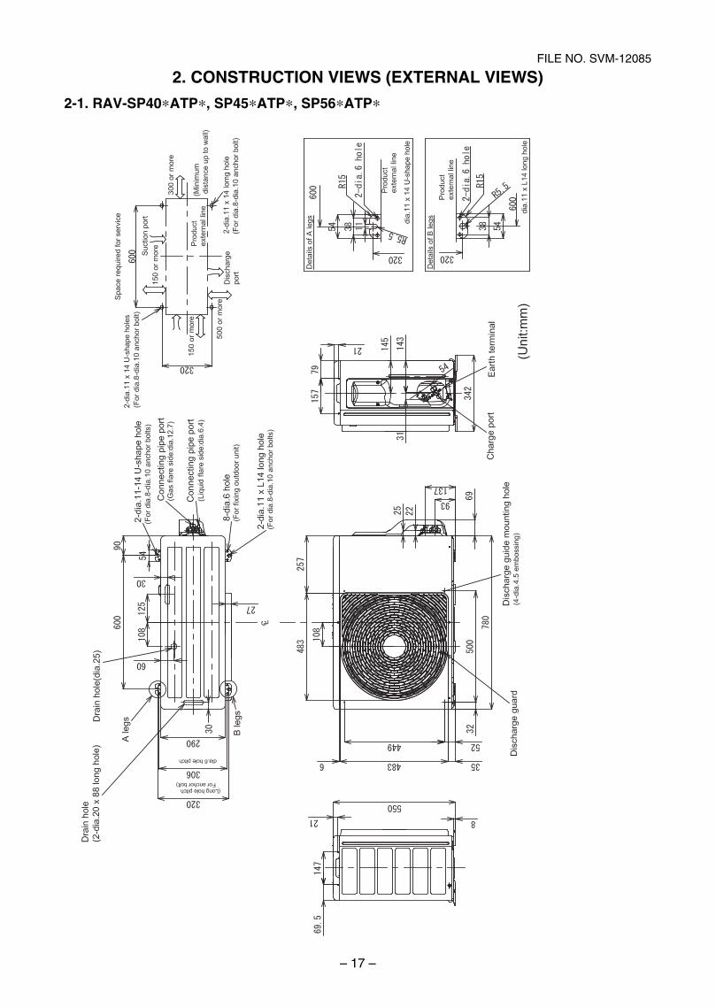
2. CONSTRUCTION VIEWS (EXTERNAL VIEWS)
2-1. RAV-SP40*ATP*, SP45*ATP*, SP56*ATP*
SVM-12085_001-050.indd 17SVM-12085_001-050.indd 17 12/06/12 11:06 AM12/06/12 11:06 AM
– 18 –
FILE NO. SVM-12085
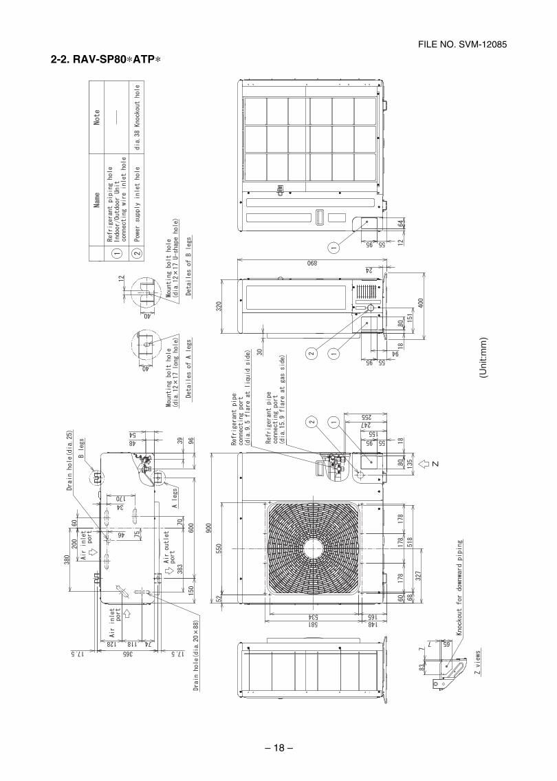
2-2. RAV-SP80*ATP*
SVM-12085_001-050.indd 18SVM-12085_001-050.indd 18 12/06/12 11:06 AM12/06/12 11:06 AM
– 19 –
FILE NO. SVM-12085
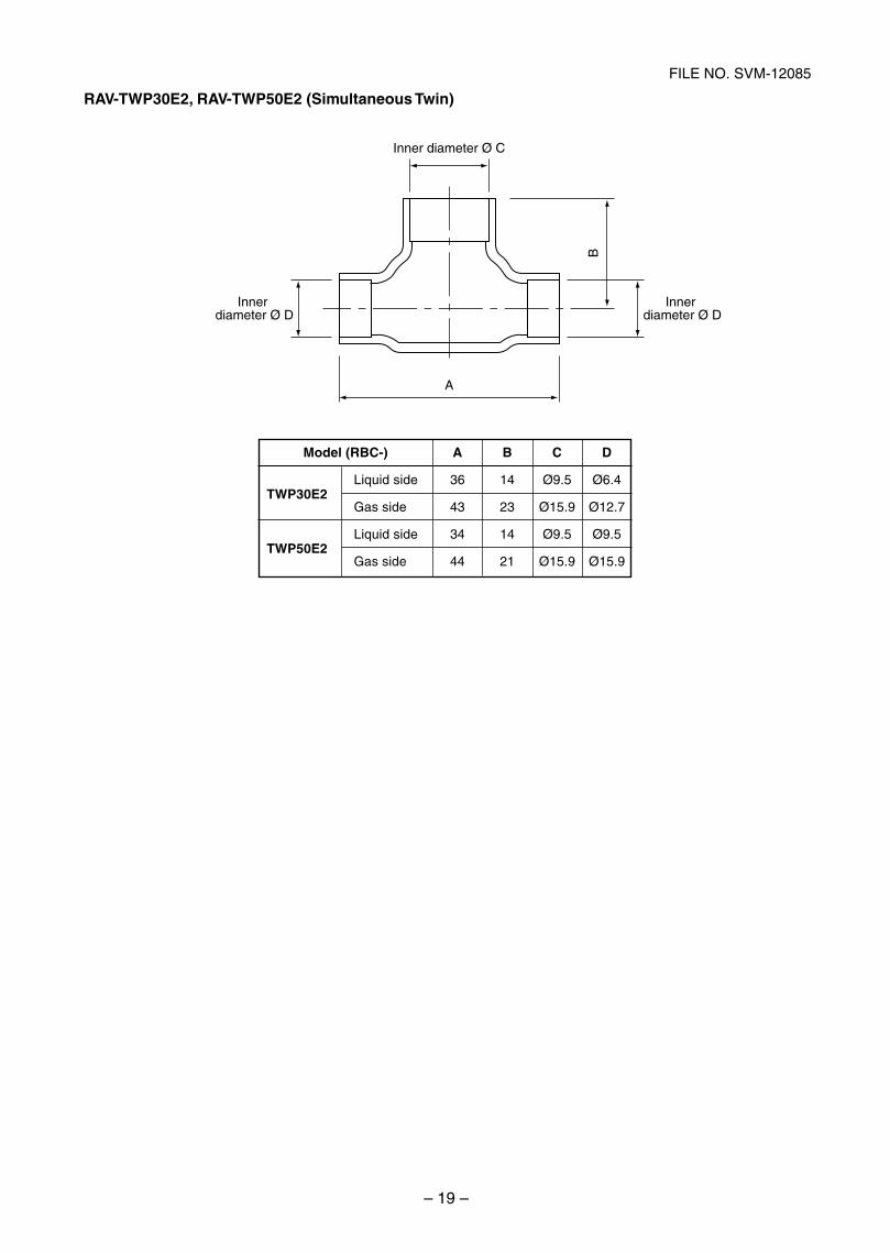
RAV-TWP30E2, RAV-TWP50E2 (Simultaneous Twin)
Inner diameter Ø C
Innerdiameter Ø D
Innerdiameter Ø D
A
B
Model (RBC-)
TWP30E2Liquid side
Gas side
TWP50E2Liquid side
Gas side
A B C D
36 14 Ø9.5 Ø6.4
43 23 Ø15.9 Ø12.7
34 14 Ø9.5 Ø9.5
44 21 Ø15.9 Ø15.9
SVM-12085_001-050.indd 19SVM-12085_001-050.indd 19 12/06/12 11:06 AM12/06/12 11:06 AM
– 20 –
FILE NO. SVM-12085
(Indoor unit A)
Refrigerant pipe at liquid side (Outer dia : ØA)
Refrigerant pipe at liquid side (Outer dia : ØC)
Refrigerant pipe at gas side (Outer dia : ØB)
Distributor(Strainer incorporated)
StrainerTCJ sensor
TC sensor
Air heatexchanger
To outdoor unit
Branch pipe
(Indoor unit B)
Refrigerant pipe at liquid side (Outer dia : ØA)
Refrigerant pipe at liquid side (Outer dia : ØD)
Refrigerant pipe at gas side (Outer dia : ØB)
Distributor(Strainer incorporated)
StrainerTCJ sensor
TC sensor
To outdoor unit
Branch pipe
Air heatexchanger
HeatingCooling
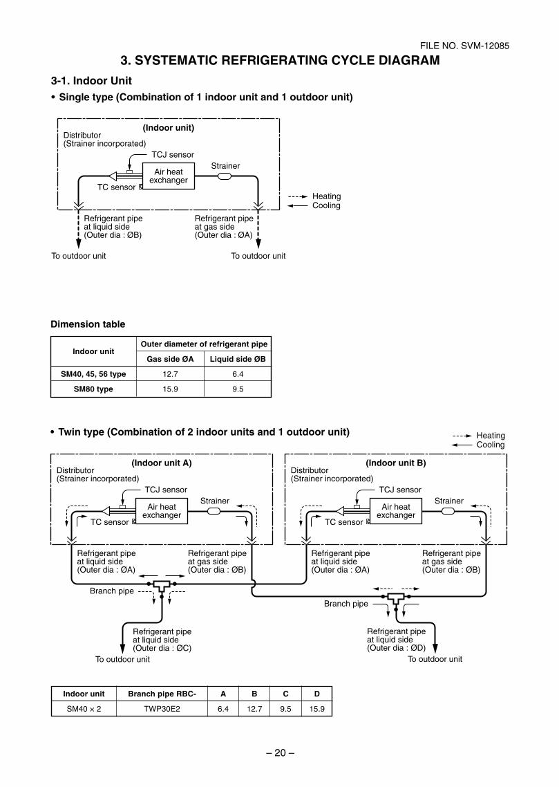
(Indoor unit)
Refrigerant pipe at liquid side (Outer dia : ØB)
Refrigerant pipe at gas side (Outer dia : ØA)
Distributor (Strainer incorporated)
Strainer
HeatingCooling
TCJ sensor
TC sensor
Air heatexchanger
To outdoor unit To outdoor unit
Single type (Combination of 1 indoor unit and 1 outdoor unit)
Twin type (Combination of 2 indoor units and 1 outdoor unit)
Indoor unit
SM40 × 2
Branch pipe RBC-
TWP30E2
A B C D
6.4 12.7 9.5 15.9
Dimension table
Indoor unit
SM40, 45, 56 type
SM80 type
Outer diameter of refrigerant pipe
Gas side ØA Liquid side ØB
12.7 6.4
15.9 9.5
3. SYSTEMATIC REFRIGERATING CYCLE DIAGRAM
3-1. Indoor Unit
SVM-12085_001-050.indd 20SVM-12085_001-050.indd 20 12/06/12 11:06 AM12/06/12 11:06 AM
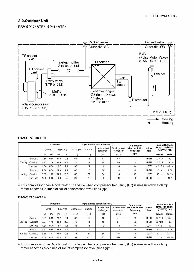
– 21 –
FILE NO. SVM-12085
Strainer
Packed valveOuter dia. ØA
Packed valve Outer dia. ØB
TS sensor
TD sensor
TO sensor
TEsensor
Distributor
4-way valve(STF-0108Z)
MufflerØ19 × L160
2-step mufflerØ19.05 × 200L
Rotary compressor(DA150A1F-20F)
Heat exchangerØ8 ripple, 2 rows, 14 stepsFP1.3 flat fin
PMV(Pulse Motor Valve)(CAM-B30YGTF-2)
R410A 1.0 kg
CoolingHeating
RAV-SP40 ATP
∗ This compressor has 4-pole motor. The value when compressor frequency (Hz) is measured by a clampmeter becomes 2 times of No. of compressor revolutions (rps).
RAV-SP45 ATP
∗ This compressor has 4-pole motor. The value when compressor frequency (Hz) is measured by a clampmeter becomes two times of No. of compressor revolutions (rps).
Standard
Cooling Overload
Low load
Standard
Heating Overload
Low load
Pressure
(MPa) (kg/cm²g)
Pd Ps Pd Ps
2.68 0.94 27.3 9.6
3.23 1.16 32.9 11.8
1.34 0.70 13.7 7.1
2.38 0.70 24.3 7.1
3.39 1.03 34.6 10.5
1.95 0.26 19.9 2.7
Pipe surface temperature (°C)
Discharge SuctionIndoor heat Outdoor heatexchanger exchanger
(TD) (TS) (TC) (TE)
61 12 11 43
77 14 15 50
36 4 2 8
65 7 39 4
83 20 54 16
90 –17 32 –19
Compressordrive revolution
frequency(rps)
47
50
44
49
49
90
Indoorfan
HIGH
HIGH
LOW
HIGH
LOW
HIGH
Indoor/Outdoortemp. conditions
(DB/WB) (°C)
Indoor Outdoor
27 / 19 35 / –
32 / 24 43 / –
18 / 15.5 –5 / –
20 / – 7 / 6
30 / – 24 / 18
15 / – –15 / –
Standard
Cooling Overload
Low load
Standard
Heating Overload
Low load
Pressure
(MPa) (kg/cm²g)
Pd Ps Pd Ps
2.81 0.89 28.7 9.1
3.24 1.16 33.0 11.8
1.34 0.70 13.7 7.1
2.53 0.68 25.8 6.9
3.39 1.03 34.6 10.5
2.00 0.25 20.4 2.6
Pipe surface temperature (°C)
Discharge SuctionIndoor heat Outdoor heatexchanger exchanger
(TD) (TS) (TC) (TE)
68 11 10 41
78 14 15 51
36 4 2 8
70 7 41 4
83 20 54 16
92 –17 33 –19
Compressordrive revolution
frequency(rps)
53
53
44
56
49
98
Indoorfan
HIGH
HIGH
LOW
HIGH
LOW
HIGH
Indoor/Outdoortemp. conditions
(DB/WB) (°C)
Indoor Outdoor
27 / 19 35 / –
32 / 24 43 / –
18 / 15.5 –5 / –
20 / – 7 / 6
30 / – 24 / 18
15 / – –15 / –
RAV-SP40 ATP , SP45 ATP
3-2.Outdoor Unit
SVM-12085_001-050.indd 21SVM-12085_001-050.indd 21 12/06/12 11:06 AM12/06/12 11:06 AM
– 22 –
FILE NO. SVM-12085
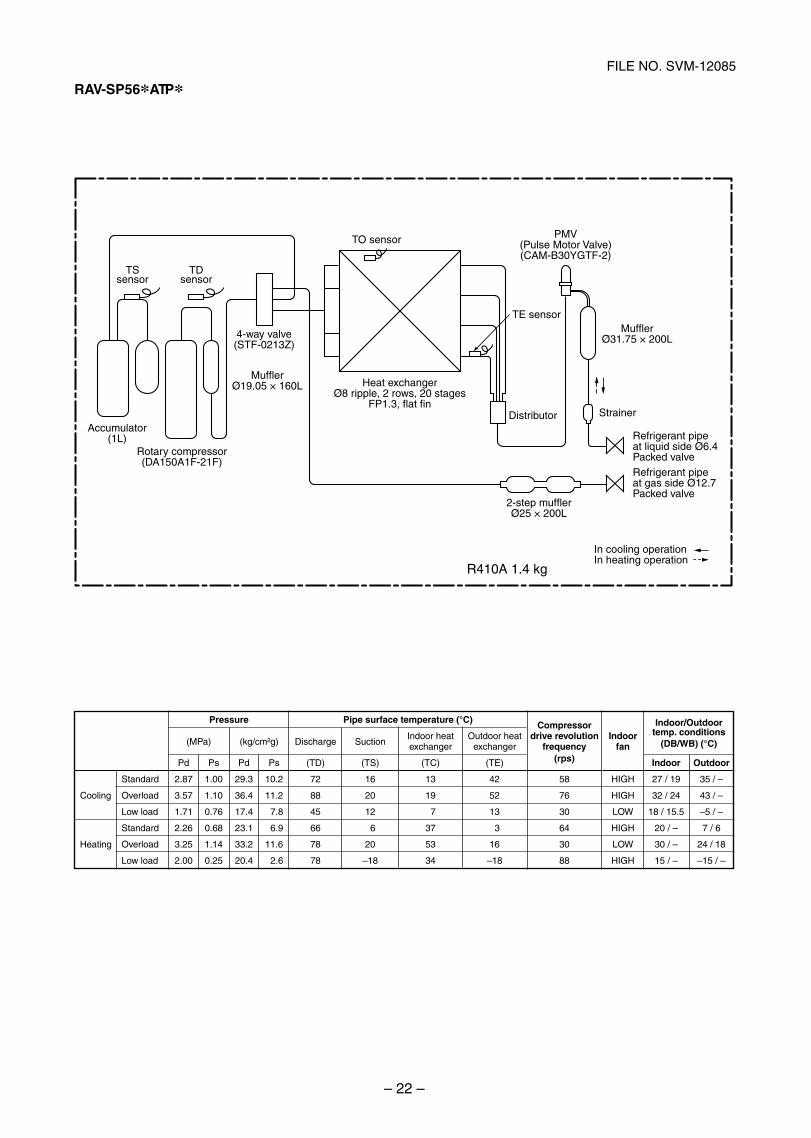
RAV-SP56 ATP
TE sensor
TO sensor
TSsensor
TDsensor
Heat exchangerØ8 ripple, 2 rows, 20 stages
FP1.3, flat fin
Accumulator(1L)
Rotary compressor(DA150A1F-21F)
Strainer
Refrigerant pipe at liquid side Ø6.4Packed valveRefrigerant pipe
R410A 1.4 kg
at gas side Ø12.7Packed valve
Distributor
In cooling operationIn heating operation
4-way valve(STF-0213Z)
2-step mufflerØ25 × 200L
MufflerØ31.75 × 200L
MufflerØ19.05 × 160L
PMV(Pulse Motor Valve)(CAM-B30YGTF-2)
Standard
Cooling Overload
Low load
Standard
Heating Overload
Low load
Pressure
(MPa) (kg/cm²g)
Pd Ps Pd Ps
2.87 1.00 29.3 10.2
3.57 1.10 36.4 11.2
1.71 0.76 17.4 7.8
2.26 0.68 23.1 6.9
3.25 1.14 33.2 11.6
2.00 0.25 20.4 2.6
Pipe surface temperature (°C)
Discharge SuctionIndoor heat Outdoor heatexchanger exchanger
(TD) (TS) (TC) (TE)
72 16 13 42
88 20 19 52
45 12 7 13
66 6 37 3
78 20 53 16
78 –18 34 –18
Compressordrive revolution
frequency(rps)
58
76
30
64
30
88
Indoorfan
HIGH
HIGH
LOW
HIGH
LOW
HIGH
Indoor/Outdoortemp. conditions
(DB/WB) (°C)
Indoor Outdoor
27 / 19 35 / –
32 / 24 43 / –
18 / 15.5 –5 / –
20 / – 7 / 6
30 / – 24 / 18
15 / – –15 / –
SVM-12085_001-050.indd 22SVM-12085_001-050.indd 22 12/06/12 11:06 AM12/06/12 11:06 AM
– 23 –
FILE NO. SVM-12085
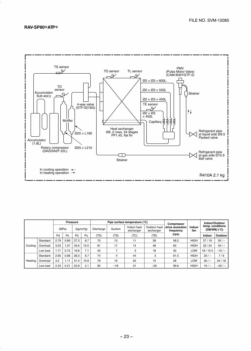
RAV-SP80 ATP
Capillary
Refrigerant pipe at liquid side Ø9.5Packed valve
Refrigerant pipe at gas side Ø15.9Ball valve
Strainer
Strainer
TDsensor
TS sensorTO sensor TL sensor
TE sensor
Heat exchangerØ8, 2 rows, 34 stages
FP1.45, flat fin
Accumulator(1.8L)
AccumulatorSub-ass’y
Rotary compressor(DA220A2F-22L)
In cooling operationIn heating operation
4-way valve(STF-0218G)
Ø25 × L180
Ø2 × Ø3 × 600L
Ø2 × Ø3 × 550L
Ø2 × Ø3 × 450L
Ø2 × Ø3× 450L
Ø25 × L210
MufflerMuffler
PMV(Pulse Motor Valve)(CAM-B30YGTF-2)
Standard
Cooling Overload
Low load
Standard
Heating Overload
Low load
Pressure
(MPa) (kg/cm²g)
Pd Ps Pd Ps
2.79 0.89 27.3 8.7
3.53 1.07 34.6 10.5
1.71 0.72 16.8 7.1
2.65 0.68 26.0 6.7
3.20 1.11 31.4 10.9
2.33 0.21 22.8 2.1
Pipe surface temperature (°C)
Discharge SuctionIndoor heat Outdoor heatexchanger exchanger
(TD) (TS) (TC) (TE)
70 13 11 39
81 17 14 48
42 7 3 18
74 4 44 3
76 19 52 15
93 –18 31 –20
Compressordrive revolution
frequency(rps)
58.2
65.0
30.0
61.5
28.0
99.6
Indoorfan
HIGH
HIGH
LOW
HIGH
LOW
HIGH
Indoor/Outdoortemp. conditions
(DB/WB) (°C)
Indoor Outdoor
27 / 19 35 / –
32 / 24 43 / –
18 / 15.5 –15 / –
20 / – 7 / 6
30 / – 24 / 18
15 / – –20 / –
R410A 2.1 kg
SVM-12085_001-050.indd 23SVM-12085_001-050.indd 23 12/06/12 11:06 AM12/06/12 11:06 AM
– 24 –
FILE NO. SVM-12085
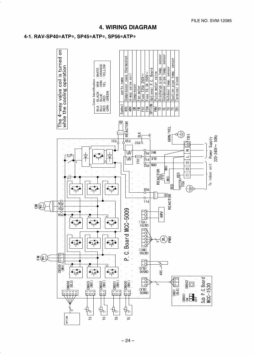
4. WIRING DIAGRAM
4-1. RAV-SP40*ATP*, SP45*ATP*, SP56*ATP*
SVM-12085_001-050.indd 24SVM-12085_001-050.indd 24 12/06/12 11:06 AM12/06/12 11:06 AM
– 25 –
FILE NO. SVM-12085
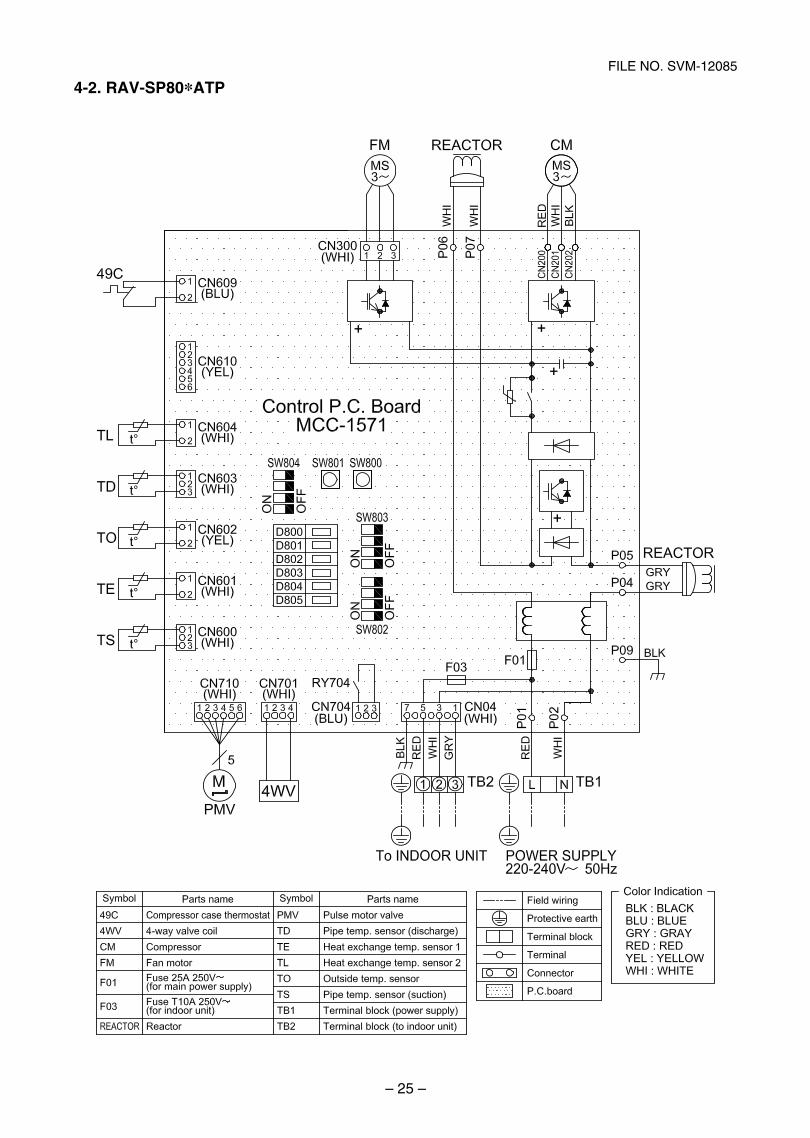
4-2. RAV-SP80*ATP
SVM-12085_001-050.indd 25SVM-12085_001-050.indd 25 12/06/12 11:06 AM12/06/12 11:06 AM
– 26 –
FILE NO. SVM-12085
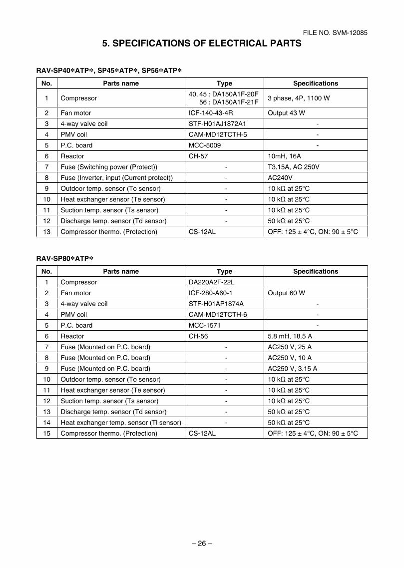
5. SPECIFICATIONS OF ELECTRICAL PARTS
RAV-SP40*ATP*, SP45*ATP*, SP56*ATP*No. Parts name Type Specifications
1 Compressor40, 45 : DA150A1F-20F 56 : DA150A1F-21F
3 phase, 4P, 1100 W
2 Fan motor ICF-140-43-4R Output 43 W
3 4-way valve coil STF-H01AJ1872A1 -
4 PMV coil CAM-MD12TCTH-5 -
5 P.C. board MCC-5009 -
6 Reactor CH-57 10mH, 16A
7 Fuse (Switching power (Protect)) - T3.15A, AC 250V
8 Fuse (Inverter, input (Current protect)) - AC240V
9 Outdoor temp. sensor (To sensor) - 10 kΩ at 25°C
10 Heat exchanger sensor (Te sensor) - 10 kΩ at 25°C
11 Suction temp. sensor (Ts sensor) - 10 kΩ at 25°C
12 Discharge temp. sensor (Td sensor) - 50 kΩ at 25°C
13 Compressor thermo. (Protection) CS-12AL OFF: 125 ± 4°C, ON: 90 ± 5°C
RAV-SP80*ATP*No. Parts name Type Specifications
1 Compressor DA220A2F-22L
2 Fan motor ICF-280-A60-1 Output 60 W
3 4-way valve coil STF-H01AP1874A -
4 PMV coil CAM-MD12TCTH-6 -
5 P.C. board MCC-1571 -
6 Reactor CH-56 5.8 mH, 18.5 A
7 Fuse (Mounted on P.C. board) - AC250 V, 25 A
8 Fuse (Mounted on P.C. board) - AC250 V, 10 A
9 Fuse (Mounted on P.C. board) - AC250 V, 3.15 A
10 Outdoor temp. sensor (To sensor) - 10 kΩ at 25°C
11 Heat exchanger sensor (Te sensor) - 10 kΩ at 25°C
12 Suction temp. sensor (Ts sensor) - 10 kΩ at 25°C
13 Discharge temp. sensor (Td sensor) - 50 kΩ at 25°C
14 Heat exchanger temp. sensor (Tl sensor) - 50 kΩ at 25°C
15 Compressor thermo. (Protection) CS-12AL OFF: 125 ± 4°C, ON: 90 ± 5°C
SVM-12085_001-050.indd 26SVM-12085_001-050.indd 26 12/06/12 11:06 AM12/06/12 11:06 AM
– 27 –
FILE NO. SVM-12085
This air conditioner adopts the new refrigerant HFC(R410A) which does not damage the ozone layer.
The working pressure of the new refrigerant R410Ais 1.6 times higher than conventional refrigerant(R22). The refrigerating oil is also changed inaccordance with change of refrigerant, so be carefulthat water, dust, and existing refrigerant orrefrigerating oil are not entered in the refrigerantcycle of the air conditioner using the new refrigerantduring installation work or servicing time.
The next section describes the precautions for airconditioner using the new refrigerant.
Conforming to contents of the next section togetherwith the general cautions included in this manual,perform the correct and safe work.
6-1. Safety During Installation/Servicing
As R410A’s pressure is about 1.6 times higher thanthat of R22, improper installation/servicing maycause a serious trouble. By using tools andmaterials exclusive for R410A, it is necessary tocarry out installation/servicing safely while takingthe following precautions into consideration.
1. Never use refrigerant other than R410A in an airconditioner which is designed to operate withR410A.
If other refrigerant than R410A is mixed,pressure in the refrigeration cycle becomesabnormally high, and it may cause personalinjury, etc. by a rupture.
2. Confirm the used refrigerant name, and usetools and materials exclusive for the refrigerantR410A.
The refrigerant name R410A is indicated on thevisible place of the outdoor unit of the airconditioner using R410A as refrigerant.
To prevent mischarging, the diameter of theservice port differs from that of R22.
3. If a refrigeration gas leakage occurs duringinstallation/servicing, be sure to ventilate fully.
If the refrigerant gas comes into contact with fire,a poisonous gas may occur.
4. When installing or removing an air conditioner,do not allow air or moisture to remain in therefrigeration cycle.
Otherwise, pressure in the refrigeration cyclemay become abnormally high so that a ruptureor personal injury may be caused.
5. After completion of installation work, check tomake sure that there is no refrigeration gasleakage.
If the refrigerant gas leaks into the room, cominginto contact with fire in the fan-driven heater,space heater, etc., a poisonous gas may occur.
6. When an air conditioning system charged with alarge volume of refrigerant is installed in a smallroom, it is necessary to exercise care so that,even when refrigerant leaks, its concentrationdoes not exceed the marginal level.
If the refrigerant gas leakage occurs and itsconcentration exceeds the marginal level, anoxygen starvation accident may result.
7. Be sure to carry out installation or removalaccording to the installation manual.
Improper installation may cause refrigerationtrouble, water leakage, electric shock, fire, etc.
8. Unauthorized modifications to the air conditionermay be dangerous. If a breakdown occursplease call a qualified air conditioner technicianor electrician.
Improper repair may result in water leakage,electric shock and fire, etc.
6-2. Refrigerant Piping Installation
6-2-1. Piping Materials and Joints Used
For the refrigerant piping installation, copper pipesand joints are mainly used.
Copper pipes and joints suitable for the refrigerantmust be chosen and installed.
Furthermore, it is necessary to use clean copperpipes and joints whose interior surfaces are lessaffected by contaminants.
1. Copper Pipes
It is necessary to use seamless copper pipeswhich are made of either copper or copper alloyand it is desirable that the amount of residual oilis less than 40 mg/10 m.
Do not use copper pipes having a collapsed,deformed or discolored portion (especially onthe interior surface).
Otherwise, the expansion valve or capillary tubemay become blocked with contaminants.
As an air conditioner using R410A incurs pres-sure higher than when using R22, it is necessaryto choose adequate materials.
Thicknesses of copper pipes used with R410Aare as shown in Table 6-2-1. Never use copperpipes thinner than 0.8mm even when it is avail-able on the market.
NOTE:Refer to the “6-6. Instructions for Re-use Pipingof R22 or R407C”.
6. REFRIGERANT R410A
SVM-12085_001-050.indd 27SVM-12085_001-050.indd 27 12/06/12 11:06 AM12/06/12 11:06 AM
– 28 –
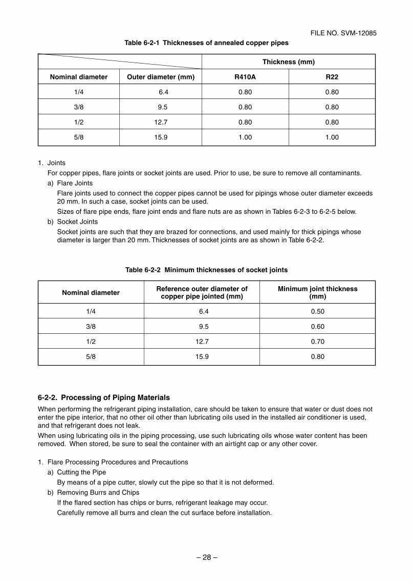
FILE NO. SVM-12085Table 6-2-1 Thicknesses of annealed copper pipes
1. Joints
For copper pipes, flare joints or socket joints are used. Prior to use, be sure to remove all contaminants.
a) Flare Joints
Flare joints used to connect the copper pipes cannot be used for pipings whose outer diameter exceeds20 mm. In such a case, socket joints can be used.
Sizes of flare pipe ends, flare joint ends and flare nuts are as shown in Tables 6-2-3 to 6-2-5 below.
b) Socket Joints
Socket joints are such that they are brazed for connections, and used mainly for thick pipings whosediameter is larger than 20 mm. Thicknesses of socket joints are as shown in Table 6-2-2.
Table 6-2-2 Minimum thicknesses of socket joints
6-2-2. Processing of Piping Materials
When performing the refrigerant piping installation, care should be taken to ensure that water or dust does notenter the pipe interior, that no other oil other than lubricating oils used in the installed air conditioner is used,and that refrigerant does not leak.
When using lubricating oils in the piping processing, use such lubricating oils whose water content has beenremoved. When stored, be sure to seal the container with an airtight cap or any other cover.
1. Flare Processing Procedures and Precautions
a) Cutting the Pipe
By means of a pipe cutter, slowly cut the pipe so that it is not deformed.
b) Removing Burrs and Chips
If the flared section has chips or burrs, refrigerant leakage may occur.
Carefully remove all burrs and clean the cut surface before installation.
Nominal diameter
1/4
3/8
1/2
5/8
Outer diameter (mm)
6.4
9.5
12.7
15.9
Thickness (mm)
22RA014R
08.008.0
08.008.0
08.008.0
00.100.1
Nominal diameter
1/4
3/8
1/2
5/8
Reference outer diameter ofcopper pipe jointed (mm)
6.4
9.5
12.7
15.9
Minimum joint thickness(mm)
0.50
0.60
0.70
0.80
SVM-12085_001-050.indd 28SVM-12085_001-050.indd 28 12/06/12 11:06 AM12/06/12 11:06 AM
– 29 –
FILE NO. SVM-12085
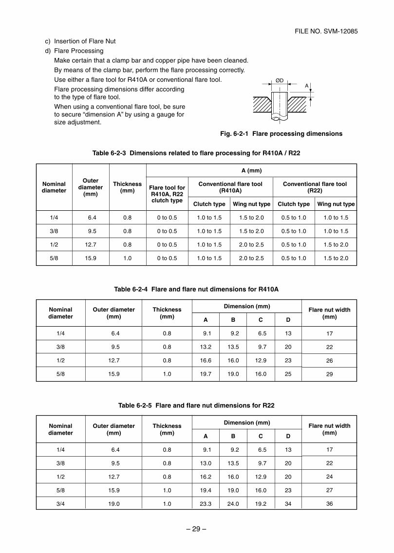
c) Insertion of Flare Nut
d) Flare Processing
Make certain that a clamp bar and copper pipe have been cleaned.
By means of the clamp bar, perform the flare processing correctly.
Use either a flare tool for R410A or conventional flare tool.
Flare processing dimensions differ accordingto the type of flare tool.
When using a conventional flare tool, be sureto secure “dimension A” by using a gauge forsize adjustment.
Fig. 6-2-1 Flare processing dimensions
Table 6-2-3 Dimensions related to flare processing for R410A / R22
AØD
Nominaldiameter
1/4
3/8
1/2
5/8
Outerdiameter
(mm)
6.4
9.5
12.7
15.9
Thickness(mm)
0.8
0.8
0.8
1.0
A (mm)
Flare tool forR410A, R22clutch type
0 to 0.5
0 to 0.5
0 to 0.5
0 to 0.5
Conventional flare tool(R410A)
Clutch type Wing nut type
1.0 to 1.5 1.5 to 2.0
1.0 to 1.5 1.5 to 2.0
1.0 to 1.5 2.0 to 2.5
1.0 to 1.5 2.0 to 2.5
Conventional flare tool(R22)
Clutch type Wing nut type
0.5 to 1.0 1.0 to 1.5
0.5 to 1.0 1.0 to 1.5
0.5 to 1.0 1.5 to 2.0
0.5 to 1.0 1.5 to 2.0
Table 6-2-4 Flare and flare nut dimensions for R410A
Table 6-2-5 Flare and flare nut dimensions for R22
Nominaldiameter
1/4
3/8
1/2
5/8
Outer diameter(mm)
6.4
9.5
12.7
15.9
Thickness(mm)
0.8
0.8
0.8
1.0
Dimension (mm)
A B C D
9.1 9.2 6.5 13
13.2 13.5 9.7 20
16.6 16.0 12.9 23
19.7 19.0 16.0 25
Flare nut width(mm)
17
22
26
29
Nominaldiameter
1/4
3/8
1/2
5/8
3/4
Outer diameter(mm)
6.4
9.5
12.7
15.9
19.0
Thickness(mm)
0.8
0.8
0.8
1.0
1.0
Dimension (mm)
A B C D
9.1 9.2 6.5 13
13.0 13.5 9.7 20
16.2 16.0 12.9 20
19.4 19.0 16.0 23
23.3 24.0 19.2 34
Flare nut width(mm)
17
22
24
27
36
SVM-12085_001-050.indd 29SVM-12085_001-050.indd 29 12/06/12 11:06 AM12/06/12 11:06 AM
– 30 –
FILE NO. SVM-12085
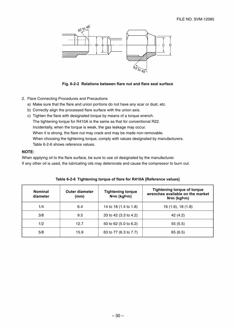
43˚to 45˚
45˚to 46˚
B A C D
Fig. 6-2-2 Relations between flare nut and flare seal surface
2. Flare Connecting Procedures and Precautions
a) Make sure that the flare and union portions do not have any scar or dust, etc.
b) Correctly align the processed flare surface with the union axis.
c) Tighten the flare with designated torque by means of a torque wrench.
The tightening torque for R410A is the same as that for conventional R22.
Incidentally, when the torque is weak, the gas leakage may occur.
When it is strong, the flare nut may crack and may be made non-removable.
When choosing the tightening torque, comply with values designated by manufacturers.
Table 6-2-6 shows reference values.
NOTE:When applying oil to the flare surface, be sure to use oil designated by the manufacturer.
If any other oil is used, the lubricating oils may deteriorate and cause the compressor to burn out.
Table 6-2-6 Tightening torque of flare for R410A [Reference values]
Nominaldiameter
1/4
3/8
1/2
5/8
Outer diameter(mm)
6.4
9.5
12.7
15.9
Tightening torque)
14 to 18 (1.4 to 1.8)
33 to 42 (3.3 to 4.2)
50 to 62 (5.0 to 6.2)
63 to 77 (6.3 to 7.7)
wrenches available on the t)
16 (1.6), 18 (1.8)
42 (4.2)
55 (5.5)
65 (6.5)
Tightening torque of torque
SVM-12085_001-050.indd 30SVM-12085_001-050.indd 30 12/06/12 11:06 AM12/06/12 11:06 AM
– 31 –
FILE NO. SVM-12085
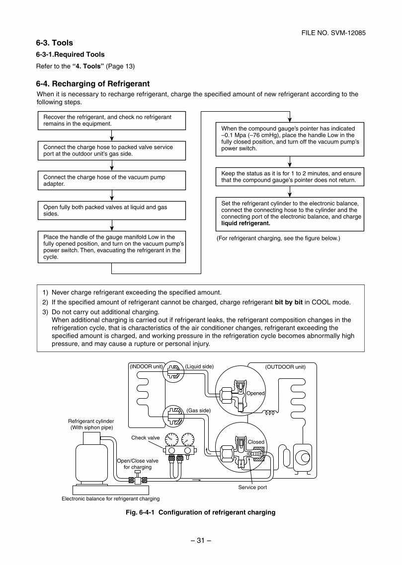
When it is necessary to recharge refrigerant, charge the specified amount of new refrigerant according to thefollowing steps.
(INDOOR unit) (Liquid side)
Refrigerant cylinder (With siphon pipe)
Check valve
(Gas side)
Open/Close valvefor charging
Electronic balance for refrigerant charging
Opened
(OUTDOOR unit)
Closed
Service port
Connect the charge hose to packed valve service port at the outdoor unit’s gas side.
Recover the refrigerant, and check no refrigerant remains in the equipment.
(For refrigerant charging, see the figure below.)
Connect the charge hose of the vacuum pump adapter.
Open fully both packed valves at liquid and gas sides.
Place the handle of the gauge manifold Low in the fully opened position, and turn on the vacuum pump’spower switch. Then, evacuating the refrigerant in the cycle.
When the compound gauge’s pointer has indicated –0.1 Mpa (–76 cmHg), place the handle Low in the fully closed position, and turn off the vacuum pump’spower switch.
Keep the status as it is for 1 to 2 minutes, and ensure that the compound gauge’s pointer does not return.
Set the refrigerant cylinder to the electronic balance, connect the connecting hose to the cylinder and the connecting port of the electronic balance, and charge liquid refrigerant.
1) Never charge refrigerant exceeding the specified amount.
2) If the specified amount of refrigerant cannot be charged, charge refrigerant bit by bit in COOL mode.
3) Do not carry out additional charging.When additional charging is carried out if refrigerant leaks, the refrigerant composition changes in therefrigeration cycle, that is characteristics of the air conditioner changes, refrigerant exceeding thespecified amount is charged, and working pressure in the refrigeration cycle becomes abnormally highpressure, and may cause a rupture or personal injury.
Fig. 6-4-1 Configuration of refrigerant charging
6-3. Tools6-3-1.Required Tools
Refer to the “4. Tools” (Page 13)
6-4. Recharging of Refrigerant
SVM-12085_001-050.indd 31SVM-12085_001-050.indd 31 12/06/12 11:06 AM12/06/12 11:06 AM
– 32 –
FILE NO. SVM-12085
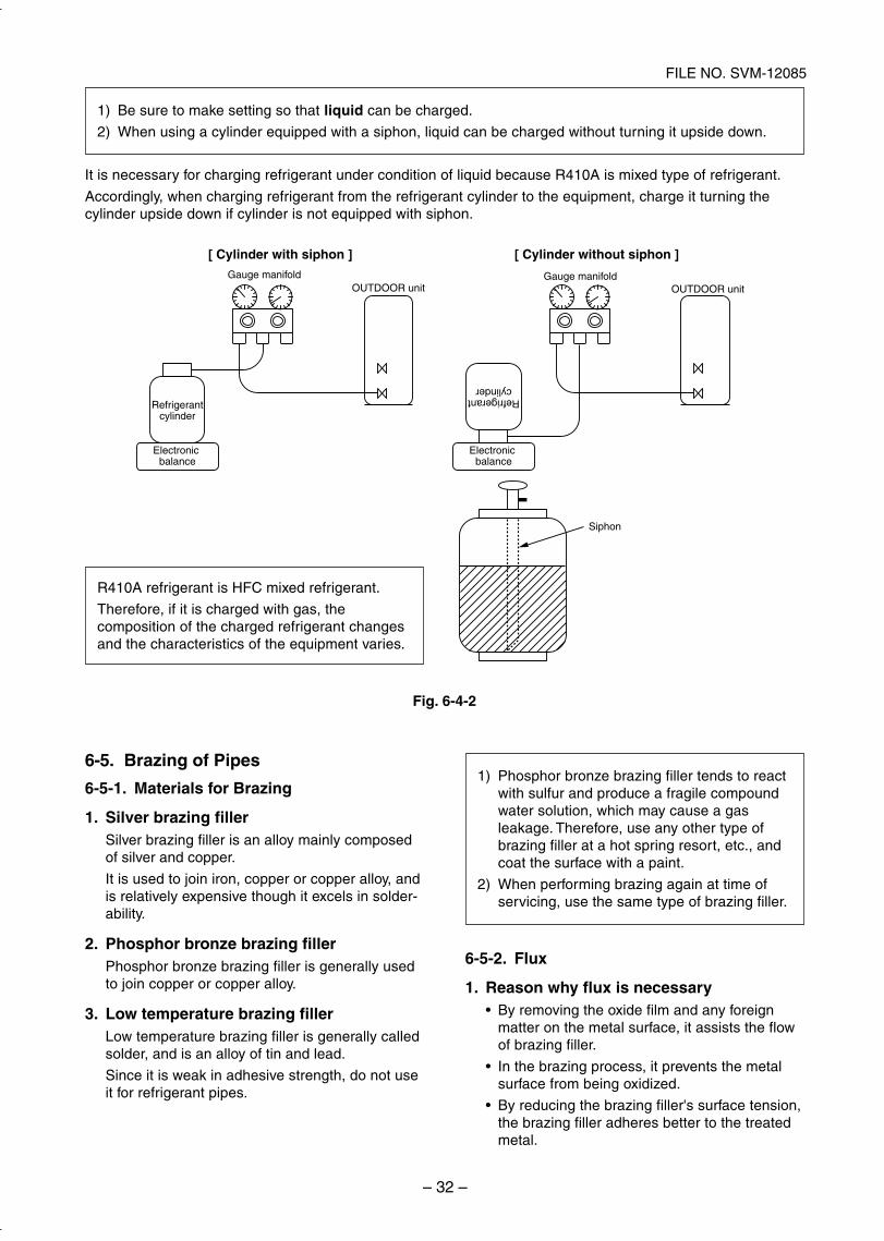
Gauge manifold
] nohpis tuohtiw rednilyC [] nohpis htiw rednilyC [
OUTDOOR unitGauge manifold
OUTDOOR unit
Refrigerantcylinder
Electronicbalance
Refrigerantcylinder
Electronicbalance
Siphon
1) Be sure to make setting so that liquid can be charged.
2) When using a cylinder equipped with a siphon, liquid can be charged without turning it upside down.
It is necessary for charging refrigerant under condition of liquid because R410A is mixed type of refrigerant.
Accordingly, when charging refrigerant from the refrigerant cylinder to the equipment, charge it turning thecylinder upside down if cylinder is not equipped with siphon.
R410A refrigerant is HFC mixed refrigerant.
Therefore, if it is charged with gas, thecomposition of the charged refrigerant changesand the characteristics of the equipment varies.
Fig. 6-4-2
6-5. Brazing of Pipes
6-5-1. Materials for Brazing
1. Silver brazing fillerSilver brazing filler is an alloy mainly composedof silver and copper.
It is used to join iron, copper or copper alloy, andis relatively expensive though it excels in solder-ability.
2. Phosphor bronze brazing fillerPhosphor bronze brazing filler is generally usedto join copper or copper alloy.
3. Low temperature brazing fillerLow temperature brazing filler is generally calledsolder, and is an alloy of tin and lead.
Since it is weak in adhesive strength, do not useit for refrigerant pipes.
1) Phosphor bronze brazing filler tends to reactwith sulfur and produce a fragile compoundwater solution, which may cause a gasleakage. Therefore, use any other type ofbrazing filler at a hot spring resort, etc., andcoat the surface with a paint.
2) When performing brazing again at time ofservicing, use the same type of brazing filler.
6-5-2. Flux
1. Reason why flux is necessaryBy removing the oxide film and any foreignmatter on the metal surface, it assists the flowof brazing filler.
In the brazing process, it prevents the metalsurface from being oxidized.
By reducing the brazing filler's surface tension,the brazing filler adheres better to the treatedmetal.
SVM-12085_001-050.indd 32SVM-12085_001-050.indd 32 12/06/12 11:06 AM12/06/12 11:06 AM
– 33 –
FILE NO. SVM-12085
Nitrogen gascylinder
Pipe
Flow meterM
Stop valve
From Nitrogen cylinder
Nitrogengas
Rubber plug
2. Characteristics required for fluxActivated temperature of flux coincides withthe brazing temperature.
Due to a wide effective temperature range, fluxis hard to carbonize.
It is easy to remove slag after brazing.
The corrosive action to the treated metal andbrazing filler is minimum.
It excels in coating performance and isharmless to the human body.
As the flux works in a complicated manner asdescribed above, it is necessary to select anadequate type of flux according to the type andshape of treated metal, type of brazing filler andbrazing method, etc.
3. Types of flux
Noncorrosive fluxGenerally, it is a compound of borax and boricacid.
It is effective in case where the brazingtemperature is higher than 800°C.
Activated fluxMost of fluxes generally used for silver brazingare this type.
It features an increased oxide film removingcapability due to the addition of compoundssuch as potassium fluoride, potassium chlorideand sodium fluoride to the borax-boric acidcompound.
4. Piping materials for brazing and usedbrazing filler/flux
1) Do not enter flux into the refrigeration cycle.
2) When chlorine contained in the flux remainswithin the pipe, the lubricating oil deteriorates.
Therefore, use a flux which does not containchlorine.
3) When adding water to the flux, use waterwhich does not contain chlorine(e.g. distilled water or ion-exchange water).
4) Remove the flux after brazing.
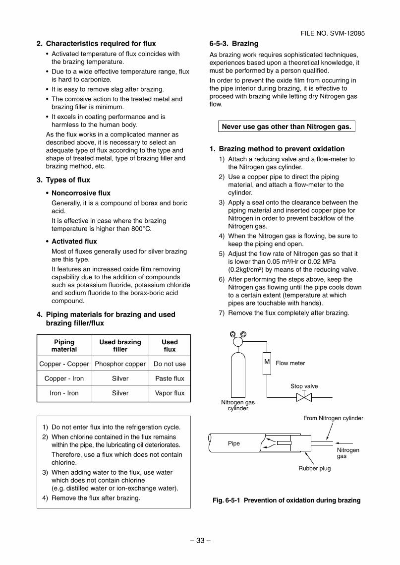
6-5-3. Brazing
As brazing work requires sophisticated techniques,experiences based upon a theoretical knowledge, itmust be performed by a person qualified.
In order to prevent the oxide film from occurring inthe pipe interior during brazing, it is effective toproceed with brazing while letting dry Nitrogen gasflow.
Never use gas other than Nitrogen gas.
1. Brazing method to prevent oxidation1) Attach a reducing valve and a flow-meter to
the Nitrogen gas cylinder.
2) Use a copper pipe to direct the pipingmaterial, and attach a flow-meter to thecylinder.
3) Apply a seal onto the clearance between thepiping material and inserted copper pipe forNitrogen in order to prevent backflow of theNitrogen gas.
4) When the Nitrogen gas is flowing, be sure tokeep the piping end open.
5) Adjust the flow rate of Nitrogen gas so that itis lower than 0.05 m³/Hr or 0.02 MPa(0.2kgf/cm²) by means of the reducing valve.
6) After performing the steps above, keep theNitrogen gas flowing until the pipe cools downto a certain extent (temperature at whichpipes are touchable with hands).
7) Remove the flux completely after brazing.
Fig. 6-5-1 Prevention of oxidation during brazing
Pipingmaterial
Copper - Copper
Copper - Iron
Iron - Iron
Used brazingfiller
Phosphor copper
Silver
Silver
Usedflux
Do not use
Paste flux
Vapor flux
SVM-12085_001-050.indd 33SVM-12085_001-050.indd 33 12/06/12 11:06 AM12/06/12 11:06 AM
– 34 –
FILE NO. SVM-12085
Instruction of Works:The existing R22 and R407C piping can bereused for our digital inverter R410A productsinstallations.
NOTE)Confirmation of existence of scratch or dent of theformer pipes to be applied and also confirmation ofreliability of the pipe strength are conventionallyreferred to the local site.
If the definite conditions can be cleared,it is possible to update the existing R22 andR407C pipes to those for R410A models.
6-6-1. Basic Conditions Needed to Reuse theExisting Pipe
Check and observe three conditions of the refrigerantpiping works.1. Dry (There is no moisture inside of the pipes.)2. Clean (There is no dust inside of the pipes.)3. Tight (There is no refrigerant leak.)
6-6-2. Restricted Items to Use the Existing PipesIn the following cases, the existing pipes cannot bereused as they are. Clean the existing pipes orexchange them with new pipes.1. When a scratch or dent is heavy, be sure to use the
new pipes for the works.2. When the thickness of the existing pipe is thinner
than the specified “Pipe diameter and thickness” besure to use the new pipes for the works.
The operating pressure of R410A is high(1.6 times of R22 and R407C). If there is a scratchor dent on the pipe or thinner pipe is used, thepressure strength is poor and may cause break-age of the pipe at the worst.
∗ Pipe diameter and thickness (mm)
6. Check the oil when the existing air conditioner wasremoved after refrigerant had been recovered.In this case, if the oil is judged as clearly differentcompared with normal oil
The refrigerator oil is copper rust green :There is possibility that moisture is mixed with theoil and rust generates inside of the pipe.There is discolored oil, a large quantity of theremains, or bad smell.A large quantity of sparkle remained wear-outpowder is observed in the refrigerator oil.
7. The air conditioner which compressor was ex-changed due to a faulty compressor.When the discolored oil, a large quantity of theremains, mixture of foreign matter, or a largequantity of sparkle remained wear-out powder isobserved, the cause of trouble will occur.
8. Installation and removal of the air conditioner arerepeated with temporary installation by lease andetc.
9. In case that type of the refrigerator oil of theexisting air conditioner is other than the following oil(Mineral oil), Suniso, Freol-S, MS (Synthetic oil),alkyl benzene (HAB, Barrel-freeze), ester series,PVE only of ether series.
Winding-insulation of the compressor maybecome inferior.
NOTE)The above descriptions are results of confirmation byour company and they are views on our airconditioners, but they do not guarantee the use of theexisting pipes of the air conditioner that adoptedR410A in other companies.
6-6-3. Branching Pipe for SimultaneousOperation System
In the concurrent twin system, when TOSHIBA-specified branching pipe is used, it can be reused.Branching pipe model name: RBC-TWP30E-2.On the existing air conditioner for simultaneousoperation system (twin system), there is a case ofusing branch pipe that has insufficient compressivestrength.In this case please change it to the branch pipe forR410A.
6-6-4. Curing of PipesWhen removing and opening the indoor unit or outdoorunit for a long time, cure the pipes as follows:
Otherwise rust may generate when moisture orforeign matter due to dewing enters in the pipes.The rust cannot be removed by cleaning, and a newpiping work is necessary.
In case that the pipe diameter is Ø12.7 mm or lessand the thickness is less than 0.7 mm, be sure touse the new pipes for works.
3. The pipes are left as coming out or gas leaks.(Poor refrigerant)
There is possibility that rain water or air includingmoisture enters in the pipe.
4. Refrigerant recovery is impossible.(Refrigerant recovery by the pump-down operationon the existing air conditioner)
There is possibility that a large quantity of pooroil or moisture remains inside of the pipe.
5. A dryer on the market is attached to the existing pipes.There is possibility that copper green rustgenerated.
Pipe outer diameter
R410A
Thickness R22(R407C)
Ø6.4 Ø9.5 Ø12.7 Ø15.9 Ø19.0
0.8 0.8 0.8 1.0 1.0
Place position
Outdoors
Indoors
Term
1 month or more
Less than 1 month
Every time
Curing manner
Pinching
Pinching or taping
6-6. Instructions for Re-use Piping of R22 or R407C
SVM-12085_001-050.indd 34SVM-12085_001-050.indd 34 12/06/12 11:06 AM12/06/12 11:06 AM
– 35 –
FILE NO. SVM-12085
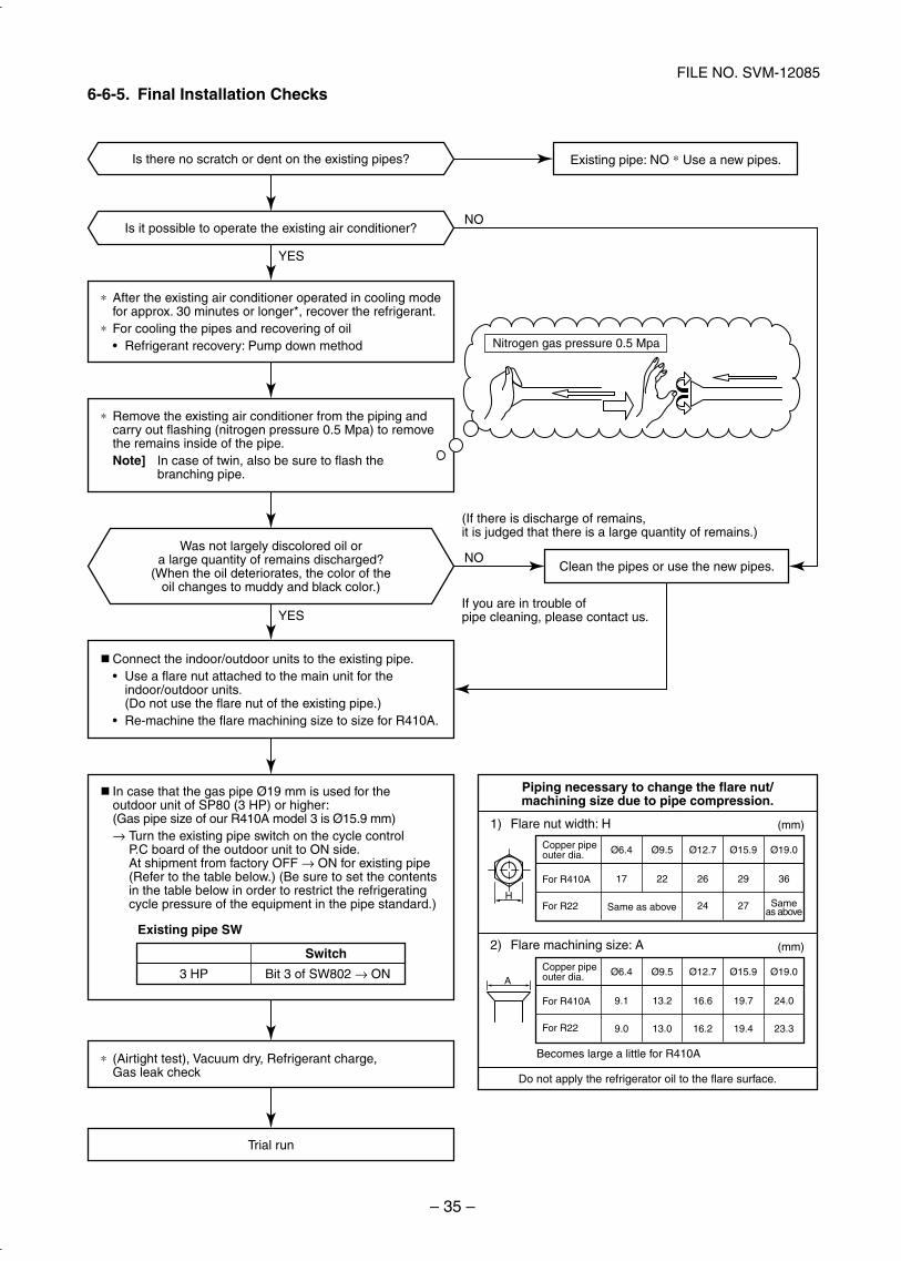
6-6-5. Final Installation Checks
Do not apply the refrigerator oil to the flare surface.
Existing pipe: NO ∗ Use a new pipes.
Clean the pipes or use the new pipes.
Trial run
Is it possible to operate the existing air conditioner?
Was not largely discolored oil ora large quantity of remains discharged?
(When the oil deteriorates, the color of theoil changes to muddy and black color.)
∗ After the existing air conditioner operated in cooling mode for approx. 30 minutes or longer*, recover the refrigerant. ∗ For cooling the pipes and recovering of oil
Refrigerant recovery: Pump down method
∗ Remove the existing air conditioner from the piping and carry out flashing (nitrogen pressure 0.5 Mpa) to remove the remains inside of the pipe.
Note] In case of twin, also be sure to flash the branching pipe.
Connect the indoor/outdoor units to the existing pipe. Use a flare nut attached to the main unit for the
indoor/outdoor units. (Do not use the flare nut of the existing pipe.)
Re-machine the flare machining size to size for R410A.
∗ (Airtight test), Vacuum dry, Refrigerant charge, Gas leak check
In case that the gas pipe Ø19 mm is used for the outdoor unit of SP80 (3 HP) or higher: (Gas pipe size of our R410A model 3 is Ø15.9 mm) → Turn the existing pipe switch on the cycle control P.C board of the outdoor unit to ON side. At shipment from factory OFF → ON for existing pipe (Refer to the table below.) (Be sure to set the contents in the table below in order to restrict the refrigerating cycle pressure of the equipment in the pipe standard.)
Existing pipe SW
Nitrogen gas pressure 0.5 Mpa
H
A
(If there is discharge of remains, it is judged that there is a large quantity of remains.)
If you are in trouble of pipe cleaning, please contact us.
Piping necessary to change the flare nut/machining size due to pipe compression.
1) Flare nut width: H
2) Flare machining size: A
(mm)
36
Ø19.0
29
Ø15.9
26
2724
Ø12.7
22
Ø9.5
17
Ø6.4
Sameas above
Copper pipeouter dia.
For R22
For R410A
Same as above
(mm)
24.0
Ø19.0
19.7
Ø15.9
16.6
Ø12.7
13.2
Ø9.5
9.1
23.319.416.213.09.0
Ø6.4Copper pipeouter dia.
For R22
For R410A
Becomes large a little for R410A
3 HP
Switch
Bit 3 of SW802 → ON
Is there no scratch or dent on the existing pipes?
YES
YES
NO
NO
SVM-12085_001-050.indd 35SVM-12085_001-050.indd 35 12/06/12 11:06 AM12/06/12 11:06 AM
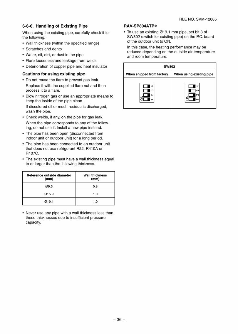
– 36 –
FILE NO. SVM-12085
6-6-6. Handling of Existing Pipe
When using the existing pipe, carefully check it forthe following:
Wall thickness (within the specified range)
Scratches and dents
Water, oil, dirt, or dust in the pipe
Flare looseness and leakage from welds
Deterioration of copper pipe and heat insulator
Cautions for using existing pipeDo not reuse the flare to prevent gas leak.
Replace it with the supplied flare nut and thenprocess it to a flare.
Blow nitrogen gas or use an appropriate means tokeep the inside of the pipe clean.
If discolored oil or much residue is discharged,wash the pipe.
Check welds, if any, on the pipe for gas leak.
When the pipe corresponds to any of the follow-ing, do not use it. Install a new pipe instead.
The pipe has been open (disconnected fromindoor unit or outdoor unit) for a long period.
The pipe has been connected to an outdoor unitthat does not use refrigerant R22, R410A orR407C.
The existing pipe must have a wall thickness equalto or larger than the following thickness.
Never use any pipe with a wall thickness less thanthese thicknesses due to insufficient pressurecapacity.
12
34
ON
12
34
ON
SW802
When shipped from factory When using existing pipe
RAV-SP804ATPTo use an existing Ø19.1 mm pipe, set bit 3 ofSW802 (switch for existing pipe) on the P.C. boardof the outdoor unit to ON.
In this case, the heating performance may bereduced depending on the outside air temperatureand room temperature.
Reference outside diameter(mm)
Ø9.5
Ø15.9
Ø19.1
Wall thickness(mm)
0.8
1.0
1.0
SVM-12085_001-050.indd 36SVM-12085_001-050.indd 36 12/06/12 11:06 AM12/06/12 11:06 AM
– 37 –
FILE NO. SVM-12085
6-7. Replenishing refrigerantIn order to assure the reliability of the appliance, the amount of refrigerant to be replenished shall be subject to the following restrictions. Follow the margin of excess replenished refrigerant, which is equivalent to the current R22. Otherwise, abnormally high pressure may be generated in the refrigeration cycle, which may result in failure, explosion of the product, or personal injury.
[Possible gas leakage]
Recharging refrigerant is allowed only if it is confirmed that the amount of leakage (e.g. slow leakage upon installation) is within the additional margin specified below.The amount of leakage is not certain if the product does not function properly (e.g. insufficient cooling / heating performance). In such case, recover the refrigerant and replenish the refrigerant.
[Restrictions for the amount of additional charging]
a. The amount of refrigerant additionally charged shall not exceed 10% of that specified. If the situation is not solved with such amount, recover the refrigerant completely and charge the specified amount.
b. In case of slow leakage upon installation and the pipe connection length of not over 15m, further tighten the flare nut or take other effective measures. Do not recharge the refrigerant.
[Cautions for recharging with refrigerant]
a. Use a scale with an accuracy of at least 10g to recharge the refrigerant. Do not use a bathroom scale.b. If the refrigerant leaks, identify the source and make sure to repair it. The refrigerant gas is not hazardous,
but if it touches a heat source (e.g. fan heater, stove), a poisonous gas may be generated.c. Use liquid refrigerant for replenishment. Replenish the refrigerant carefully and slowly.
SVM-12085_001-050.indd 37SVM-12085_001-050.indd 37 12/06/12 11:06 AM12/06/12 11:06 AM

– 38 –
FILE NO. SVM-12085
Frequency normal down
Frequency slow down
Frequency hold
Frequency slow up(Up to command)
As command is
Abnormal stop
TD [˚C]
(117) 111
(107) 109
(105) 106
(102) 103
(93) 96
SP40 to SP56 in theparentheses
1. PMV (Pulse Motor Valve) control1) PMV is controlled between (SP40 to SP56: 20 to 500, SP80: 30 to 500) pulsed during operation.
2) In cooling operation, PMV is usually controlled with the temperature difference between TS sensor andTC sensor aiming (SP40 to SP56: 2 to 5K, SP80: 1 to 4K) as the target value.
3) In heating operation, PMV is usually controlled with the temperature difference between TS sensor andTE sensor aiming (SP40 to SP56: –2 to 4K, SP80: 2 to 4K) as the target value.
4) When the cycle excessively heated in both cooling and heating operation, PMV is controlled by TD sensor.
The target value is 101°C for both cooling and heating operations in SP40 to SP56, and 91°C for coolingoperation and 96°C for heating operation respectively in SP80.
REQUIREMENT
A sensor trouble may cause a liquid back-flow or abnormal overheat resulting in excessive shortening of thecompressor life.
In a case of trouble on the compressor, be sure to check there is no error in the resistance value or therefrigerating cycle of each sensor after repair and then start the operation.
2. Discharge temperature release control1) When the discharge temperature did not fall or the discharge temperature rapidly went up by PMV
control, this control lowers the operation frequency.
It subdivides the frequency control up to 0.6Hz to stabilize the cycle.
2) When the discharge temperature detected an abnormal stop zone, the compressor stops and thenrestarts after 2 minutes 30 seconds.
The error counting is cleared when the operation continued for A minutes. If the error is detected byB times without clearing, the error is determined and restarting is not performed.
∗ The cause is considered as excessively little amount of refrigerant, PMV error or clogging of the cycle.
3) For displayed contents of error, confirm on the check code list.
SP40 to SP80 SP56
A 6 10
B 8 4
7. OUTDOOR CONTROL CIRCUIT
7-1. Outdoor Controls
SVM-12085_001-050.indd 38SVM-12085_001-050.indd 38 12/06/12 11:06 AM12/06/12 11:06 AM
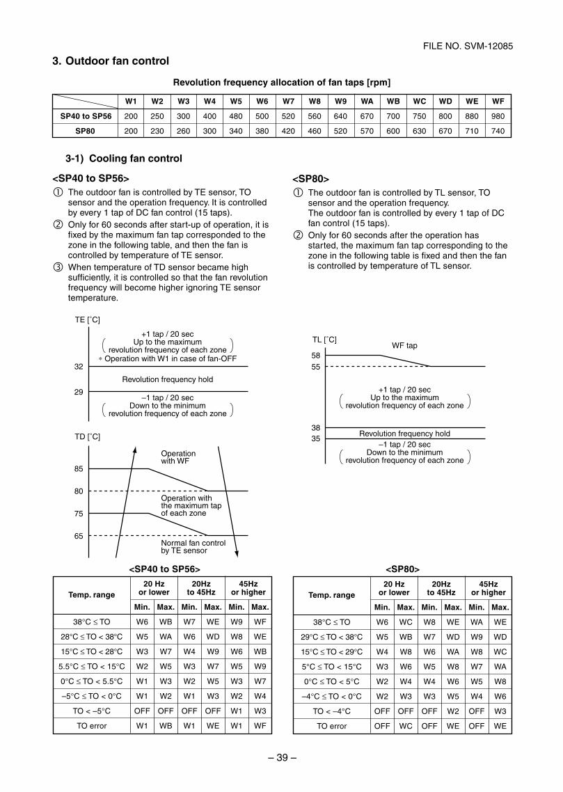
– 39 –
FILE NO. SVM-12085
3. Outdoor fan control
Revolution frequency allocation of fan taps [rpm]
WF tap
+1 tap / 20 secUp to the maximum
revolution frequency of each zone
Revolution frequency hold–1 tap / 20 sec
Down to the minimumrevolution frequency of each zone
TL [˚C]
5855
3835
Temp. range
38°C ≤ TO
29°C ≤ TO < 38°C
15°C ≤ TO < 29°C
5°C ≤ TO < 15°C
0°C ≤ TO < 5°C
–4°C ≤ TO < 0°C
TO < –4°C
TO error
20 Hz 20Hz 45Hzor lower to 45Hz or higher
Min. Max. Min. Max. Min. Max.
W6 WC W8 WE WA WE
W5 WB W7 WD W9 WD
W4 W8 W6 WA W8 WC
W3 W6 W5 W8 W7 WA
W2 W4 W4 W6 W5 W8
W2 W3 W3 W5 W4 W6
OFF OFF OFF W2 OFF W3
OFF WC OFF WE OFF WE
<SP80>The outdoor fan is controlled by TL sensor, TOsensor and the operation frequency.The outdoor fan is controlled by every 1 tap of DCfan control (15 taps).Only for 60 seconds after the operation hasstarted, the maximum fan tap corresponding to thezone in the following table is fixed and then the fanis controlled by temperature of TL sensor.
+1 tap / 20 secUp to the maximum
revolution frequency of each zone∗ Operation with W1 in case of fan-OFF
Revolution frequency hold
Operation with the maximum tap of each zone
Operation with WF
Normal fan control by TE sensor
–1 tap / 20 secDown to the minimum
revolution frequency of each zone
TE [˚C]
TD [˚C]
85
80
75
65
32
29
3-1) Cooling fan control
<SP40 to SP56>The outdoor fan is controlled by TE sensor, TOsensor and the operation frequency. It is controlledby every 1 tap of DC fan control (15 taps).Only for 60 seconds after start-up of operation, it isfixed by the maximum fan tap corresponded to thezone in the following table, and then the fan iscontrolled by temperature of TE sensor.When temperature of TD sensor became highsufficiently, it is controlled so that the fan revolutionfrequency will become higher ignoring TE sensortemperature.
SP40 to SP56
SP80
W1 W2 W3 W4 W5 W6 W7 W8 W9 WA WB WC WD WE WF
200 250 300 400 480 500 520 560 640 670 700 750 800 880 980
200 230 260 300 340 380 420 460 520 570 600 630 670 710 740
Temp. range
38°C ≤ TO
28°C ≤ TO < 38°C
15°C ≤ TO < 28°C
5.5°C ≤ TO < 15°C
0°C ≤ TO < 5.5°C
–5°C ≤ TO < 0°C
TO < –5°C
TO error
20 Hz 20Hz 45Hzor lower to 45Hz or higher
Min. Max. Min. Max. Min. Max.
W6 WB W7 WE W9 WF
W5 WA W6 WD W8 WE
W3 W7 W4 W9 W6 WB
W2 W5 W3 W7 W5 W9
W1 W3 W2 W5 W3 W7
W1 W2 W1 W3 W2 W4
OFF OFF OFF OFF W1 W3
W1 WB W1 WE W1 WF
<SP40 to SP56> <SP80>
SVM-12085_001-050.indd 39SVM-12085_001-050.indd 39 12/06/12 11:06 AM12/06/12 11:06 AM
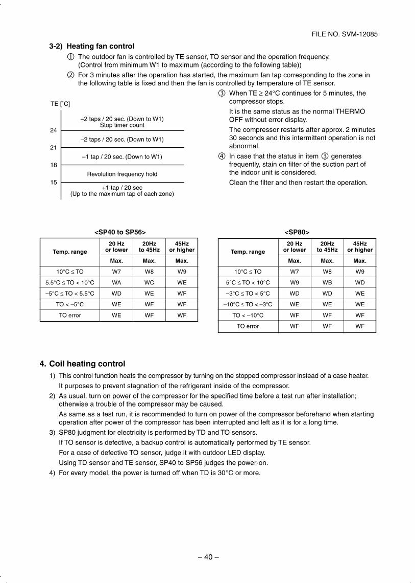
– 40 –
FILE NO. SVM-12085
3-2) Heating fan controlThe outdoor fan is controlled by TE sensor, TO sensor and the operation frequency.(Control from minimum W1 to maximum (according to the following table))
For 3 minutes after the operation has started, the maximum fan tap corresponding to the zone inthe following table is fixed and then the fan is controlled by temperature of TE sensor.
>08PS<<SP40 to SP56>
–2 taps / 20 sec. (Down to W1)Stop timer count
+1 tap / 20 sec(Up to the maximum tap of each zone)
–2 taps / 20 sec. (Down to W1)
–1 tap / 20 sec. (Down to W1)
Revolution frequency hold
TE [˚C]
24
21
18
15
Temp. range
10°C ≤ TO
5°C ≤ TO < 10°C
–3°C ≤ TO < 5°C
–10°C ≤ TO < –3°C
TO < –10°C
TO error
20 Hz 20Hz 45Hzor lower to 45Hz or higher
Max. Max. Max.
W7 W8 W9
W9 WB WD
WD WD WE
WE WE WE
WF WF WF
WF WF WF
Temp. range
10°C ≤ TO
5.5°C ≤ TO < 10°C
–5°C ≤ TO < 5.5°C
TO < –5°C
TO error
20 Hz 20Hz 45Hzor lower to 45Hz or higher
Max. Max. Max.
W7 W8 W9
WA WC WE
WD WE WF
WE WF WF
WE WF WF
When TE ≥ 24°C continues for 5 minutes, thecompressor stops.
It is the same status as the normal THERMOOFF without error display.
The compressor restarts after approx. 2 minutes30 seconds and this intermittent operation is notabnormal.
In case that the status in item generatesfrequently, stain on filter of the suction part ofthe indoor unit is considered.
Clean the filter and then restart the operation.
4. Coil heating control1) This control function heats the compressor by turning on the stopped compressor instead of a case heater.
It purposes to prevent stagnation of the refrigerant inside of the compressor.
2) As usual, turn on power of the compressor for the specified time before a test run after installation;otherwise a trouble of the compressor may be caused.
As same as a test run, it is recommended to turn on power of the compressor beforehand when startingoperation after power of the compressor has been interrupted and left as it is for a long time.
3) SP80 judgment for electricity is performed by TD and TO sensors.
If TO sensor is defective, a backup control is automatically performed by TE sensor.
For a case of defective TO sensor, judge it with outdoor LED display.
Using TD sensor and TE sensor, SP40 to SP56 judges the power-on.
4) For every model, the power is turned off when TD is 30°C or more.
SVM-12085_001-050.indd 40SVM-12085_001-050.indd 40 12/06/12 11:06 AM12/06/12 11:06 AM
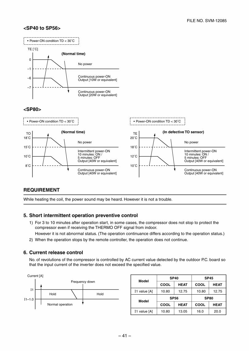
– 41 –
FILE NO. SVM-12085
<SP80>
Intermittent power-ON10 minutes: ON / 5 minutes: OFFOutput [40W or equivalent]
Continuous power-ONOutput [40W or equivalent]
No power
)rosnes OT evitcefed nI()emit lamroN(TO
15˚C
10˚C
8˚C
18˚C
Power-ON condition TD < 30˚C
Intermittent power-ON10 minutes: ON / 5 minutes: OFFOutput [40W or equivalent]
Continuous power-ONOutput [40W or equivalent]
No power
TE
18˚C
12˚C
10˚C
20˚C
Power-ON condition TD < 30˚C
REQUIREMENT
While heating the coil, the power sound may be heard. However it is not a trouble.
5. Short intermittent operation preventive control1) For 3 to 10 minutes after operation start, in some cases, the compressor does not stop to protect the
compressor even if receiving the THERMO OFF signal from indoor.
However it is not abnormal status. (The operation continuance differs according to the operation status.)
2) When the operation stops by the remote controller, the operation does not continue.
6. Current release controlNo. of revolutions of the compressor is controlled by AC current value detected by the outdoor P.C. board sothat the input current of the inverter does not exceed the specified value.
Continuous power-ONOutput [10W or equivalent]
Continuous power-ONOutput [20W or equivalent]
No power
(Normal time)TE [˚C]
–1
–6
–7
0
Power-ON condition TD < 30˚C
<SP40 to SP56>
1–1.0
1
Current [A]
Normal operation
Frequency down
dloHdloH
Model
1 value [A]
SP40 SP45
COOL HEAT COOL HEAT
10.80 12.75 10.80 12.75
Model
1 value [A]
SP56 SP80
COOL HEAT COOL HEAT
10.80 13.05 16.0 20.0
SVM-12085_001-050.indd 41SVM-12085_001-050.indd 41 12/06/12 11:06 AM12/06/12 11:06 AM
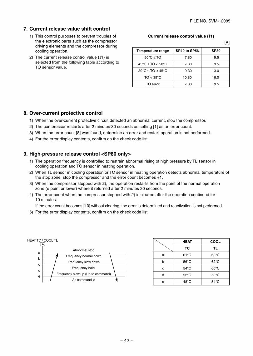
– 42 –
FILE NO. SVM-12085
Abnormal stop
Frequency normal down
Frequency slow down
Frequency hold
Frequency slow up (Up to command)
As command is
HEAT TC / COOL TL[˚C]
e
d
c
b
a
7. Current release value shift control1) This control purposes to prevent troubles of
the electronic parts such as the compressordriving elements and the compressor duringcooling operation.
2) The current release control value ( 1) isselected from the following table according toTO sensor value.
Current release control value ( 1)
[A]
Temperature range
50°C ≤ TO
45°C ≤ TO < 50°C
39°C ≤ TO < 45°C
TO < 39°C
TO error
SP40 to SP56 SP80
7.80 9.5
7.80 9.5
9.30 13.0
10.80 16.0
7.80 9.5
8. Over-current protective control1) When the over-current protective circuit detected an abnormal current, stop the compressor.
2) The compressor restarts after 2 minutes 30 seconds as setting [1] as an error count.
3) When the error count [8] was found, determine an error and restart operation is not performed.
4) For the error display contents, confirm on the check code list.
9. High-pressure release control <SP80 only>1) The operation frequency is controlled to restrain abnormal rising of high pressure by TL sensor in
cooling operation and TC sensor in heating operation.
2) When TL sensor in cooling operation or TC sensor in heating operation detects abnormal temperature ofthe stop zone, stop the compressor and the error count becomes +1.
3) When the compressor stopped with 2), the operation restarts from the point of the normal operationzone (e point or lower) where it returned after 2 minutes 30 seconds.
4) The error count when the compressor stopped with 2) is cleared after the operation continued for10 minutes.
If the error count becomes [10] without clearing, the error is determined and reactivation is not performed.
5) For the error display contents, confirm on the check code list.
a
b
c
d
e
HEAT COOL
TC TL
61°C 63°C
56°C 62°C
54°C 60°C
52°C 58°C
48°C 54°C
SVM-12085_001-050.indd 42SVM-12085_001-050.indd 42 12/06/12 11:06 AM12/06/12 11:06 AM
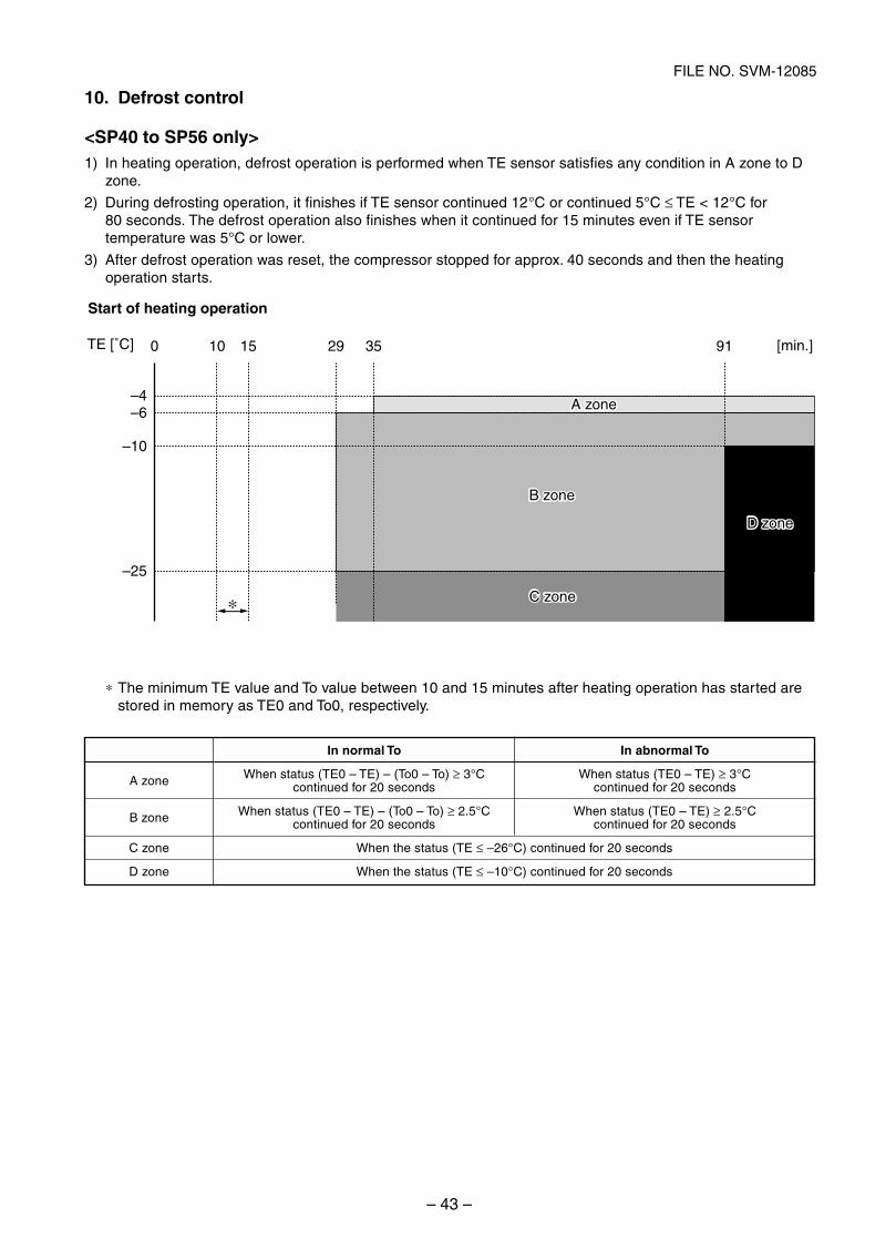
– 43 –
FILE NO. SVM-12085
10. Defrost control
<SP40 to SP56 only>1) In heating operation, defrost operation is performed when TE sensor satisfies any condition in A zone to D
zone.
2) During defrosting operation, it finishes if TE sensor continued 12°C or continued 5°C ≤ TE < 12°C for80 seconds. The defrost operation also finishes when it continued for 15 minutes even if TE sensor temperature was 5°C or lower.
3) After defrost operation was reset, the compressor stopped for approx. 40 seconds and then the heatingoperation starts.
∗ The minimum TE value and To value between 10 and 15 minutes after heating operation has started arestored in memory as TE0 and To0, respectively.
0 10 15 29 35 91 [min.]
∗
TE [˚C]
–4–6
–10
–25
A zoneA zone
B zoneB zone
C zoneC zone
Start of heating operation
D zoneD zone
A zone
B zone
C zone
D zone
oT lamronba nIoT lamron nI
When status (TE0 – TE) – (To0 – To) ≥ 3°C When status (TE0 – TE) ≥ 3°Csdnoces 02 rof deunitnocsdnoces 02 rof deunitnoc
When status (TE0 – TE) – (To0 – To) ≥ 2.5°C When status (TE0 – TE) ≥ 2.5°Csdnoces 02 rof deunitnocsdnoces 02 rof deunitnoc
When the status (TE ≤ –26°C) continued for 20 seconds
When the status (TE ≤ –10°C) continued for 20 seconds
SVM-12085_001-050.indd 43SVM-12085_001-050.indd 43 12/06/12 11:06 AM12/06/12 11:06 AM
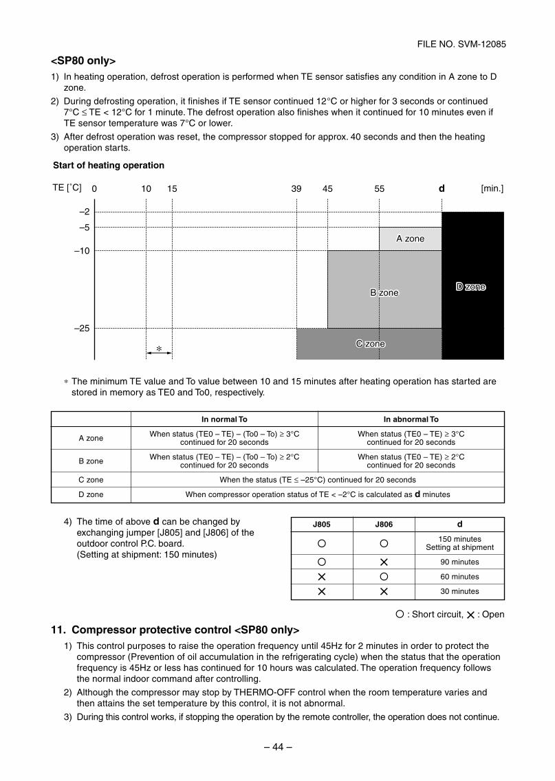
– 44 –
FILE NO. SVM-12085
<SP80 only>1) In heating operation, defrost operation is performed when TE sensor satisfies any condition in A zone to D
zone.
2) During defrosting operation, it finishes if TE sensor continued 12°C or higher for 3 seconds or continued7°C ≤ TE < 12°C for 1 minute. The defrost operation also finishes when it continued for 10 minutes even ifTE sensor temperature was 7°C or lower.
3) After defrost operation was reset, the compressor stopped for approx. 40 seconds and then the heatingoperation starts.
0 10 15 4539 55 d [min.]
∗
TE [˚C]
–2
–5
–10
–25
A zoneA zone
B zoneB zone
C zoneC zone
Start of heating operation
D zoneD zone
∗ The minimum TE value and To value between 10 and 15 minutes after heating operation has started arestored in memory as TE0 and To0, respectively.
4) The time of above d can be changed byexchanging jumper [J805] and [J806] of theoutdoor control P.C. board.(Setting at shipment: 150 minutes)
: Short circuit, × : Open
11. Compressor protective control <SP80 only>1) This control purposes to raise the operation frequency until 45Hz for 2 minutes in order to protect the
compressor (Prevention of oil accumulation in the refrigerating cycle) when the status that the operationfrequency is 45Hz or less has continued for 10 hours was calculated. The operation frequency followsthe normal indoor command after controlling.
2) Although the compressor may stop by THERMO-OFF control when the room temperature varies andthen attains the set temperature by this control, it is not abnormal.
3) During this control works, if stopping the operation by the remote controller, the operation does not continue.
J805 J806
××× ×
d
150 minutesSetting at shipment
90 minutes
60 minutes
30 minutes
A zone
B zone
C zone
D zone
oT lamronba nIoT lamron nI
When status (TE0 – TE) – (To0 – To) ≥ 3°C When status (TE0 – TE) ≥ 3°Csdnoces 02 rof deunitnocsdnoces 02 rof deunitnoc
When status (TE0 – TE) – (To0 – To) ≥ 2°C When status (TE0 – TE) ≥ 2°Csdnoces 02 rof deunitnocsdnoces 02 rof deunitnoc
When the status (TE ≤ –25°C) continued for 20 seconds
When compressor operation status of TE < –2°C is calculated as d minutes
SVM-12085_001-050.indd 44SVM-12085_001-050.indd 44 12/06/12 11:06 AM12/06/12 11:06 AM
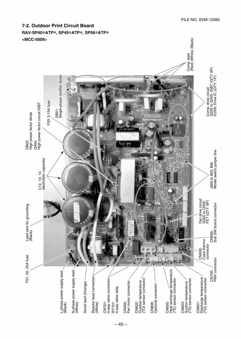
– 45 –
FILE NO. SVM-12085
F01
, 02,
25A
fuse
Lead
wire
for
grou
ndin
g (B
lack
)
DB
01:
Sin
gle-
phas
e re
ctifi
er d
iode
Com
p. le
ad
(Red
) (W
hite
) (B
lack
)
DB
02:
Hig
h po
wer
fact
or d
iode
Q40
4:
Hig
h po
wer
fact
or c
ircui
t IG
BT
F03
: 3.1
5A fu
se
C12
, 13,
14
e lec
trol
ytic
cap
acito
r
CN
500:
C
ase
ther
mo
conn
ecto
r
Fan
driv
e ci
rcui
tQ
300
to Q
305:
FE
T (
QT
Y: 6
P)
12V
12V
5V5VG
ND
GN
D
I C80
0: M
CU
CN
700:
P
MV
con
nect
orC
N60
5:S
ub S
W b
oard
con
nect
orJ8
00 to
803
, 806
Mod
el s
witc
h ju
mpe
r lin
e
Com
p. d
rive
circ
uit
Q20
0 to
Q20
5: IG
BT
(Q
TY
: 6P
)IC
200:
Driv
e IC
(Q
TY
: 1P
)
L-ph
ase
pow
er s
uppl
y le
ad
(Bla
ck)
N-p
hase
pow
er s
uppl
y le
ad
(Whi
te)
Ser
ial l
ead
(Ora
nge)
Rea
ctor
lead
con
nect
or
(Whi
te)
CN
300:
Fan
mot
or c
onne
ctor
CN
602:
Out
door
tem
pera
ture
(T
O)
sens
or c
onne
ctor
CN
806:
Opt
iona
l con
nect
or
CN
600:
H
eat e
xcha
nge
tem
pera
ture
(T
E)
sens
or c
onne
ctor
CN
603:
S
uctio
n te
mpe
ratu
re
(TS
) se
nsor
con
nect
or
CN
601:
D
isch
arge
tem
pera
ture
(T
D)
sens
or c
onne
ctor
CN
701:
4-w
ay v
alve
con
nect
orR
Y70
1:4-
way
val
ve r
elay
IC80
0: M
CU
DB
01:
Sin
gle-
phas
e re
ctifi
er d
iode
F03
: 3.1
5A fu
se
C12
, 13,
14
elec
trol
ytic
cap
acito
r
7-2. Outdoor Print Circuit BoardRAV-SP40*ATP*, SP45*ATP*, SP56*ATP*<MCC-5009>
SVM-12085_001-050.indd 45SVM-12085_001-050.indd 45 12/06/12 11:06 AM12/06/12 11:06 AM
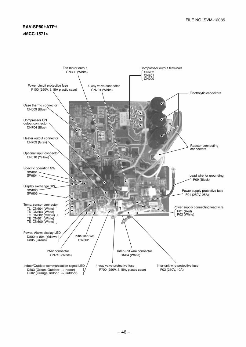
– 46 –
FILE NO. SVM-12085
Case thermo connector CN609 (Blue)
4-way valve connector CN701 (White)
Compressor ON output connector
CN704 (Blue)
Heater output connector CN703 (Gray)
Optional input connector CN610 (Yellow)
Specific operation SWSW801SW804
Display exchange SWSW800SW803
Temp. sensor connectorTL CN604 (White)TD CN603 (White)TO CN602 (Yellow)TE CN601 (White)TS CN600 (White)
Power, Alarm display LEDD800 to 804 (Yellow)D805 (Green)
Initial set SWSW802
Power circuit protective fuseF100 (250V, 3.15A plastic case)
Fan motor outputCN300 (White)
Compressor output terminalsCN202CN201CN200
Electrolytic capacitors
Reactor connecting connectors
Power supply connecting lead wireP01 (Red)P02 (White)
Lead wire for groundingP09 (Black)
PMV connectorCN710 (White)
Inter-unit wire connectorCN04 (White)
4-way valve protective fuseF700 (250V, 3.15A, plastic case)
Inter-unit wire protective fuseF03 (250V, 10A)
Indoor/Outdoor communication signal LEDD503 (Green, Outdoor → Indoor)D502 (Orange, Indoor → Outdoor)
Power supply protective fuseF01 (250V, 25A)
RAV-SP80*ATP*<MCC-1571>
SVM-12085_001-050.indd 46SVM-12085_001-050.indd 46 12/06/12 11:06 AM12/06/12 11:06 AM
– 47 –
FILE NO. SVM-12085
<Wired remote controller type>
1. Before troubleshooting1) Required tools/instruments
+ and – screwdrivers, spanners, radio cutting pliers, nippers, push pins for reset switch
Tester, thermometer, pressure gauge, etc.
2) Confirmation points before check
a) The following operations are normal.
1. Compressor does not operate.
Is not 3-minutes delay (3 minutes after compressor OFF)?
Is not the outdoor unit in standby status though the remote controller reached the setuptemperature?
Does not timer operate during fan operation?
Is not an overflow error detected on the indoor unit?
Is not outside high-temperature operation controlled in heating operation?
2. Indoor fan does not rotate.
Does not cool air discharge preventive control work in heating operation?
3. Outdoor fan does not rotate or air volume changes.
Does not high-temperature release operation control work in heating operation?
Does not outside low-temperature operation control work in cooling operation?
Is not defrost operation performed?
4. ON/OFF operation cannot be performed from remote controller.
Is not the control operation performed from outside/remote side?
Is not automatic address being set up?(When the power is turned on at the first time or when indoor unit address setting is changed, theoperation cannot be performed for maximum approx. 5 minutes after power-ON.)
Is not being carried out a test run by operation of the outdoor controller?
b) Did you return the cabling to the initial positions?
c) Are connecting cables of indoor unit and remote controller correct?
2. Troubleshooting procedureWhen a trouble occurred, check the parts along with the following procedure.
Trouble Confirmation of check code display Check defective position and parts.→→
NOTE :For cause of a trouble, power conditions or malfunction/erroneous diagnosis of microcomputer due to outernoise is considered except the items to be checked. If there is any noise source, change the cables of theremote controller to shield cables.
8. TROUBLESHOOTING
8-1. Summary of Troubleshooting
SVM-12085_001-050.indd 47SVM-12085_001-050.indd 47 12/06/12 11:06 AM12/06/12 11:06 AM
– 48 –
FILE NO. SVM-12085
<Wireless remote controller type>
1. Before troubleshooting1) Required tools/instruments
+ and – screwdrivers, spanners, radio cutting pliers, nippers, etc.
Tester, thermometer, pressure gauge, etc.
2) Confirmation points before check
a) The following operations are normal.
1. Compressor does not operate.
Is not 3-minutes delay (3 minutes after compressor OFF)?
Is not the outdoor unit in standby status though the remote controller reached the setuptemperature?
Does not timer operate during fan operation?
Is not an overflow error detected on the indoor unit?
Is not outside high-temperature operation controlled in heating operation?
2. Indoor fan does not rotate.
Does not cool air discharge preventive control work in heating operation?
3) Outdoor fan does not rotate or air volume changes.
Does not high-temperature release operation control work in heating operation?
Does not outside low-temperature operation control work in cooling operation?
Is not defrost operation performed?
4) ON/OFF operation cannot be performed from remote controller.
Is not forced operation performed?
Is not the control operation performed from outside/remote side?
Is not automatic address being set up?
Is not being carried out a test run by operation of the outdoor controller?
a) Did you return the cabling to the initial positions?
b) Are connecting cables between indoor unit and receiving unit correct?
2. Troubleshooting procedure(When the power is turned on at the first time or when indoor unit address setting is changed, the operationcannot be performed for maximum approx. 5 minutes after power-ON.)
When a trouble occurred, check the parts along with the following procedure.
1) Outline of judgment
The primary judgment to check where a trouble occurred in indoor unit or outdoor unit is performed withthe following method.
Method to judge the erroneous position by flashing indication on the display part of indoor unit(sensors of the receiving unit)
The indoor unit monitors operating status of the air conditioner, and the blocked contents ofself-diagnosis are displayed restricted to the following cases if a protective circuit works.
Trouble →→Confirmation of lamp display(When 4-way air discharge cassette typewireless remote controller is connected)
Check defectiveposition and parts.
SVM-12085_001-050.indd 48SVM-12085_001-050.indd 48 12/06/12 11:06 AM12/06/12 11:06 AM
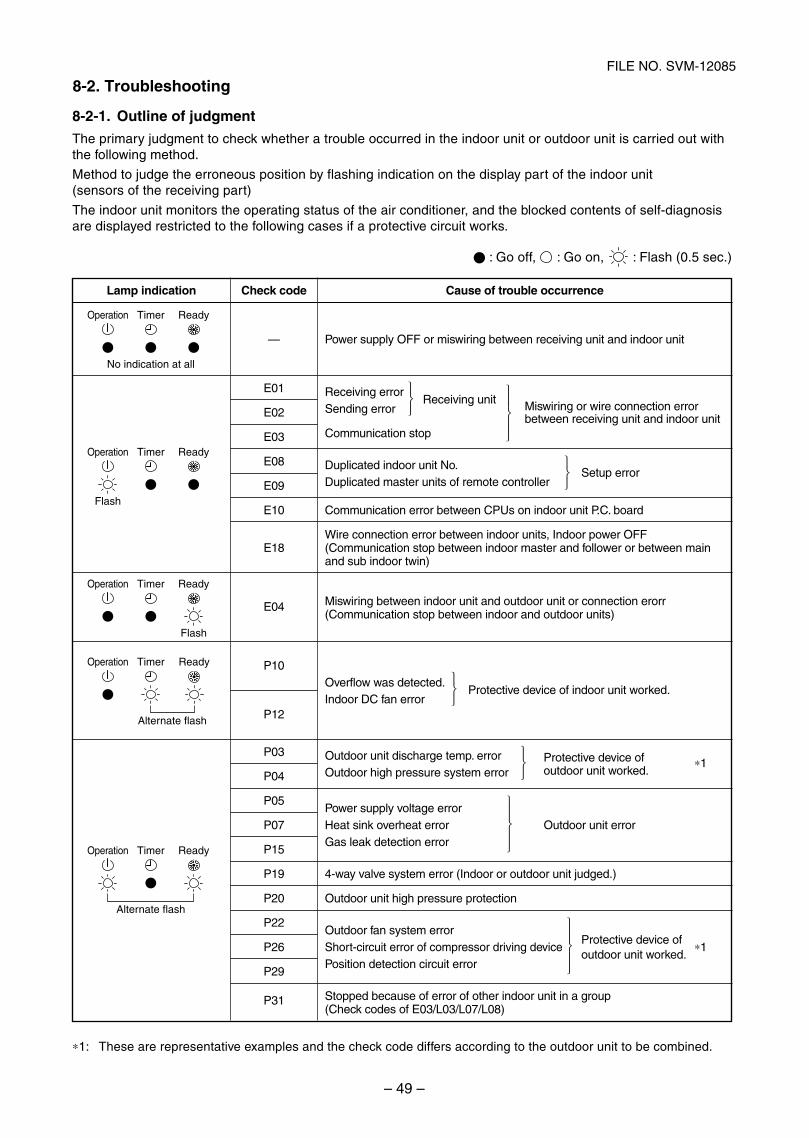
– 49 –
FILE NO. SVM-12085
8-2-1. Outline of judgment
The primary judgment to check whether a trouble occurred in the indoor unit or outdoor unit is carried out withthe following method.
Method to judge the erroneous position by flashing indication on the display part of the indoor unit(sensors of the receiving part)
The indoor unit monitors the operating status of the air conditioner, and the blocked contents of self-diagnosisare displayed restricted to the following cases if a protective circuit works.
: Go off, : Go on, : Flash (0.5 sec.)
⎫⎪⎬⎪⎭
⎫⎬⎭
⎫⎬⎭
⎫⎪⎬⎪⎭
⎫⎬⎭
⎫⎬⎭
⎫⎪⎬⎪⎭
∗1: These are representative examples and the check code differs according to the outdoor unit to be combined.
Lamp indication
Operation Timer Ready
No indication at all
Operation Timer Ready
Flash
Operation Timer Ready
Flash
Operation Timer Ready
Alternate flash
Operation Timer Ready
Alternate flash
Check code
—
E01
E02
E03
E08
E09
E10
E18
E04
P10
P12
P03
P04
P05
P07
P15
P19
P20
P22
P26
P29
P31
Cause of trouble occurrence
Power supply OFF or miswiring between receiving unit and indoor unit
Receiving errorReceiving unit Miswiring or wire connection errorSending error
Communication stopbetween receiving unit and indoor unit
Duplicated indoor unit No.Setup error
Duplicated master units of remote controller
Communication error between CPUs on indoor unit P.C. board
Wire connection error between indoor units, Indoor power OFF(Communication stop between indoor master and follower or between mainand sub indoor twin)
Miswiring between indoor unit and outdoor unit or connection erorr(Communication stop between indoor and outdoor units)
Overflow was detected.Protective device of indoor unit worked.
Indoor DC fan error
Outdoor unit discharge temp. error Protective device of ∗1Outdoor high pressure system error outdoor unit worked.
Power supply voltage errorHeat sink overheat error Outdoor unit errorGas leak detection error
4-way valve system error (Indoor or outdoor unit judged.)
Outdoor unit high pressure protection
Outdoor fan system errorProtective device of
Short-circuit error of compressor driving device ∗1Position detection circuit error
outdoor unit worked.
Stopped because of error of other indoor unit in a group(Check codes of E03/L03/L07/L08)
8-2. Troubleshooting
SVM-12085_001-050.indd 49SVM-12085_001-050.indd 49 12/06/12 11:06 AM12/06/12 11:06 AM
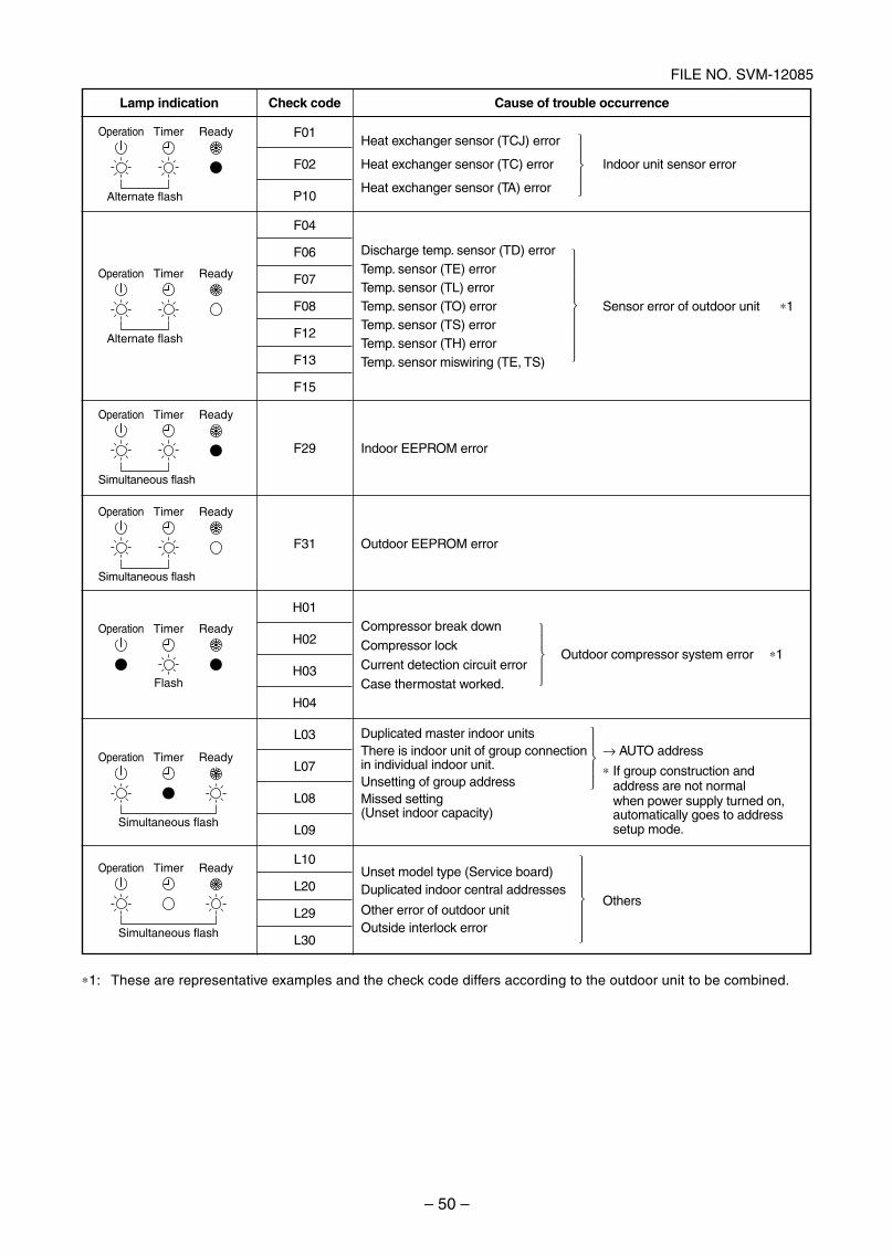
– 50 –
FILE NO. SVM-12085
∗1: These are representative examples and the check code differs according to the outdoor unit to be combined.
⎫⎪⎬⎪⎭
⎫⎪⎪⎪⎬⎪⎪⎪⎭
⎫⎪⎬⎪⎭
⎫⎪⎬⎪⎭
Lamp indication
Operation Timer Ready
Alternate flash
Operation Timer Ready
Alternate flash
Operation Timer Ready
Simultaneous flash
Operation Timer Ready
Simultaneous flash
Operation Timer Ready
Flash
Operation Timer Ready
Simultaneous flash
Operation Timer Ready
Simultaneous flash
Check code
F01
F02
P10
F04
F06
F07
F08
F12
F13
F15
F29
F31
H01
H02
H03
H04
L03
L07
L08
L09
L10
L20
L29
L30
Cause of trouble occurrence
Heat exchanger sensor (TCJ) error
Heat exchanger sensor (TC) error Indoor unit sensor error
Heat exchanger sensor (TA) error
Discharge temp. sensor (TD) errorTemp. sensor (TE) errorTemp. sensor (TL) errorTemp. sensor (TO) error Sensor error of outdoor unit ∗1Temp. sensor (TS) errorTemp. sensor (TH) errorTemp. sensor miswiring (TE, TS)
Indoor EEPROM error
Outdoor EEPROM error
Compressor break down
Compressor lock
Current detection circuit errorOutdoor compressor system error ∗1
Case thermostat worked.
Duplicated master indoor unitsThere is indoor unit of group connection → AUTO addressin individual indoor unit. ∗ If group construction andUnsetting of group address address are not normalMissed setting when power supply turned on,(Unset indoor capacity) automatically goes to address
setup mode.
Unset model type (Service board)Duplicated indoor central addresses
Other error of outdoor unitOthers
Outside interlock error
⎫⎪⎪⎬⎪⎪⎭
SVM-12085_001-050.indd 50SVM-12085_001-050.indd 50 12/06/12 11:06 AM12/06/12 11:06 AM
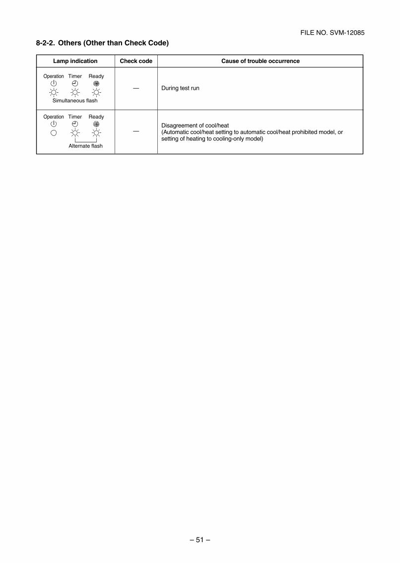
– 51 –
FILE NO. SVM-12085
8-2-2. Others (Other than Check Code)
Lamp indication
Operation Timer Ready
Simultaneous flash
Operation Timer Ready
Alternate flash
Check code
—
—
Cause of trouble occurrence
During test run
Disagreement of cool/heat(Automatic cool/heat setting to automatic cool/heat prohibited model, orsetting of heating to cooling-only model)
SVM-12085_051-114.indd 51SVM-12085_051-114.indd 51 12/06/12 11:15 AM12/06/12 11:15 AM
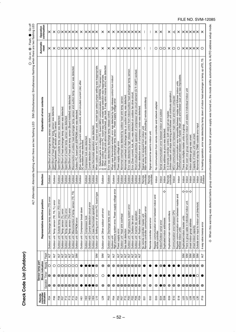
– 52 –
FILE NO. SVM-12085C
hec
k C
od
e L
ist
(Ou
tdo
or)
: G
o on
, :
Fla
sh,
: G
o of
f A
LT (
Alte
rnat
e): A
ltern
ate
flash
ing
whe
n th
ere
are
two
flash
ing
LED
SIM
(S
imul
tane
ous)
: Sim
ulta
neou
s fla
shin
g w
hen
ther
e ar
e tw
o fla
shin
g LE
D
Whe
n th
is w
arni
ng w
as d
etec
ted
befo
re g
roup
con
stru
ctio
n/ad
dres
s ch
eck
finis
h at
pow
er s
uppl
y w
as t
urne
d on
, th
e m
ode
shift
s au
tom
atic
ally
to
AU
TO
add
ress
set
up m
ode.
Rem
ote
con
tro
ller
ind
icat
ion
F04
F06
F08
F07
F12
F13
F15
F31
H01
H02
H03
H04
L10
L29
P03
P04
P05
P07
P15
P20
P22
P26
P29
E01
E02
E03
E04
E08
E09
E10
E18
L03
L07
L08
L09
L30
P19
Sen
sor
lam
p p
art
Blo
ck in
dic
atio
n O
pera
tion
Tim
er R
eady
Fla
shA
LT
ALT
ALT
ALT
ALT
ALT
ALT
SIM
SIM
SIM
ALT
ALT
ALT
ALT
ALT
ALT
ALT
ALT
ALT
SIM
SIM
SIM
SIM
SIM
ALT
Rep
rese
nta
tive
def
ecti
ve p
osi
tio
n
Out
door
uni
t D
isch
arge
tem
p. s
enso
r (T
D)
erro
r
Out
door
uni
t Te
mp.
sen
sor
(TE
, TS
, TL)
err
or
Out
door
uni
t O
utsi
de te
mp.
sen
sor
(TO
) er
ror
Out
door
uni
t Te
mp.
sen
sor
(TL)
err
orO
utdo
or u
nit
Tem
p. s
enso
r (T
S)
erro
rO
utdo
or u
nit
Tem
p. s
enso
r (T
H)
erro
rO
utdo
or u
nit
Mis
conn
ectio
n of
tem
p. s
enso
r (T
E, T
S)
Out
door
uni
t E
EP
RO
M e
rror
Out
door
uni
t C
ompr
esso
r br
eak
dow
n
Out
door
uni
t C
ompr
esso
r lo
ckO
utdo
or u
nit
Cur
rent
det
ectio
n ci
rcui
t err
orO
utdo
or u
nit
Cas
e th
erm
osta
t ope
ratio
nO
utdo
or u
nit
Set
ting
erro
r of
ser
vice
P.C
. boa
rd ty
pe
Out
door
uni
t O
ther
out
door
uni
t err
or
Out
door
uni
t D
isch
arge
tem
p. e
rror
Out
door
uni
tH
igh
pres
sure
sys
tem
err
or, P
ower
sup
ply
volta
ge e
rror
Pow
er s
uppl
y er
ror
Out
door
uni
t H
eat s
ink
over
heat
Gas
leak
det
ectio
nO
utdo
or u
nit
Hig
h pr
essu
re s
yste
m e
rror
Out
door
uni
t O
utdo
or fa
n er
ror
Out
door
uni
t In
vert
er Id
c op
erat
ion
Out
door
uni
t P
ositi
on d
etec
tion
erro
rN
o re
mot
e co
ntro
ller
mas
ter
unit
Rem
ote
cont
rolle
r co
mm
unic
atio
n er
ror
Rem
ote
cont
rolle
r se
nd e
rror
Reg
ular
com
mun
icat
ion
erro
r be
twee
n in
door
and
rem
ote
cont
rolle
rIn
door
/Out
door
ser
ial e
rror
Dup
licat
ed in
door
add
ress
es
Dup
licat
ed m
ain
rem
ote
cont
rolle
rs
Com
mun
icat
ion
erro
r be
twee
n C
PU
Reg
ular
com
mun
icat
ion
erro
r be
twee
n m
aste
r an
dfo
llow
er in
door
uni
tsD
uplic
ated
indo
or m
aste
r un
itsT
here
is g
roup
cab
le in
indi
vidu
al in
door
uni
t.U
nset
indo
or g
roup
add
ress
Uns
et in
door
cap
acity
Out
side
err
or in
put t
o in
door
uni
t (In
terlo
ck)
4-w
ay v
alve
inve
rse
erro
r
Det
ecti
on
Out
door
Out
door
Out
door
Out
door
Out
door
Out
door
Out
door
Out
door
Out
door
Out
door
Out
door
Out
door
Out
door
Out
door
Out
door
Out
door
Out
door
Out
door
Out
door
Out
door
Out
door
Out
door
Out
door
Rem
ote
cont
rolle
rR
emot
eco
ntro
ller
Indo
or
Indo
orIn
door
Rem
ote
cont
rolle
rIn
door
Indo
or
Indo
orIn
door
Indo
orIn
door
Indo
orIn
door
Out
door
Exp
lan
atio
n o
f err
or
con
ten
ts
Ope
n/S
hort
of d
isch
arge
tem
p. s
enso
r w
as d
etec
ted.
Ope
n/S
hort
of h
eat e
xcha
nger
tem
p. s
enso
r w
as d
etec
ted.
Mis
wiri
ng b
etw
een
TE
sen
sor
and
TS
sen
sor
Ope
n/S
hort
of o
utsi
de te
mp.
sen
sor
was
det
ecte
d.O
pen/
Sho
rt o
f hea
t exc
hang
er te
mp.
sen
sor
was
det
ecte
d.O
pen/
Sho
rt o
f suc
tion
tem
p. s
enso
r w
as d
etec
ted.
Ope
n/S
hort
of h
eat s
ink
tem
p. s
enso
r (B
oard
inst
alle
d) w
as d
etec
ted.
Mis
conn
ectio
n of
out
door
hea
t exc
hang
er te
mp.
sen
sor
and
suct
ion
tem
p. s
enso
r w
as d
etec
ted.
Out
door
P.C
. boa
rd p
art (
EE
PR
OM
) er
ror
was
det
ecte
d.W
hen
reac
hed
min
-Hz
by c
urre
nt r
elea
se c
ontr
ol, s
hort
-circ
uite
d cu
rren
t (Id
c) a
fter
DC
exc
itatio
n w
as d
etec
ted.
Com
pres
sor
lock
was
det
ecte
d.C
urre
nt d
etec
tion
circ
uit e
rror
Cas
e th
erm
osta
t ope
ratio
n w
as d
etec
ted.
Whe
n ou
tdoo
r se
rvic
e P.
C. b
oard
was
use
d, m
odel
type
sel
ect j
umpe
r se
tting
was
inap
prop
riate
.1)
Def
ectiv
e pa
rts
on o
utdo
or P
.C. b
oard
(M
CU
com
mun
icat
ion,
EE
PR
OM
, TH
sen
sor
erro
r)2)
Whe
n ou
tdoo
r se
rvic
e P.
C. b
oard
was
use
d, m
odel
type
sel
ectio
n w
as in
appr
opria
te.
3)O
ther
err
or (
Hea
t sin
k ab
norm
al o
verh
eat,
gas
leak
, 4-w
ay v
alve
inve
rse
erro
r) w
as d
etec
ted.
Err
or w
as d
etec
ted
by d
isch
arge
tem
p. r
elea
se c
ontr
ol.
Whe
n ca
se th
erm
osta
t wor
ked,
err
or w
as d
etec
ted
by h
igh
rele
ase
cont
rol f
rom
indo
or/
outd
oor
heat
exc
hang
er te
mp.
sen
sor.
Pow
er s
uppl
y vo
ltage
err
orP
ower
sup
ply
volta
ge e
rror
Abn
orm
al o
verh
eat w
as d
etec
ted
by o
utdo
or h
eat s
ink
tem
p. s
enso
r.A
bnor
mal
ove
rhea
t of d
isch
arge
tem
p. o
r su
ctio
n te
mp.
was
det
ecte
d.E
rror
was
det
ecte
d by
hig
h re
leas
e co
ntro
l fro
m in
door
/out
door
hea
t exc
hang
er te
mp.
sen
sor.
Err
or (
Ove
r-cu
rren
t, lo
ck, e
tc.)
was
det
ecte
d on
out
door
fan
driv
e ci
rcui
t.S
hort
-circ
uite
d pr
otec
tive
oper
atio
n of
com
pres
sor
driv
e ci
rcui
t ele
men
t (G
-Tr
/IGB
T)
wor
ked.
Pos
ition
det
ectio
n er
ror
of c
ompr
esso
r m
otor
was
det
ecte
d.S
igna
l was
not
rec
eive
d fr
om in
door
uni
t.M
ain
rem
ote
cont
rolle
r w
as n
ot s
et. (
incl
udin
g 2
rem
ote
cont
rolle
rs)
Sig
nal c
anno
t be
sent
to in
door
uni
t.
No
com
mun
icat
ion
from
rem
ote
cont
rolle
r an
d ne
twor
k ad
apte
r
Ser
ial c
omm
unic
atio
n er
ror
betw
een
indo
or a
nd o
utdo
orS
ame
addr
ess
as y
ours
was
det
ecte
d.In
2-r
emot
e co
ntro
ller
cont
rol,
both
wer
e se
t as
mas
ter.
(Ind
oor
mas
ter
unit
stop
s w
arni
ng a
nd fo
llow
er u
nit c
ontin
ues
oper
atio
n.)
MC
U c
omm
unic
atio
n er
ror
betw
een
mai
n m
otor
and
mic
ro c
ompu
ter
Reg
ular
com
mun
icat
ion
was
impo
ssib
le b
etw
een
mas
ter
and
follo
wer
indo
or u
nits
.C
omm
unic
atio
n be
twee
n tw
in m
aste
r (M
ain
unit)
and
follo
wer
(su
b un
it) w
as im
poss
ible
.T
here
are
mul
tiple
mas
ter
units
in a
gro
up.
Whe
n ev
en o
ne g
roup
con
nect
ion
indo
or u
nit e
xist
s in
indi
vidu
al in
door
uni
tIn
door
add
ress
gro
up w
as u
nset
.C
apac
ity o
f ind
oor
unit
was
uns
et.
Abn
orm
al s
top
by C
N80
out
side
err
or in
put
In h
eatin
g op
erat
ion,
err
or w
as d
etec
ted
by te
mp.
dow
n of
indo
or h
eat e
xcha
nger
or
tem
p. u
p of
TE
, TS
.
Au
tom
atic
Op
erat
ion
rese
tco
ntin
uatio
n
××
××
××
××
××
××
××
××
××
××
××
××
××
××
××
××
××
××
××
××
××
××
——
—— × ×
×× ×
××
××
××
××
×× ×
SVM-12085_051-114.indd 52SVM-12085_051-114.indd 52 12/06/12 11:15 AM12/06/12 11:15 AM
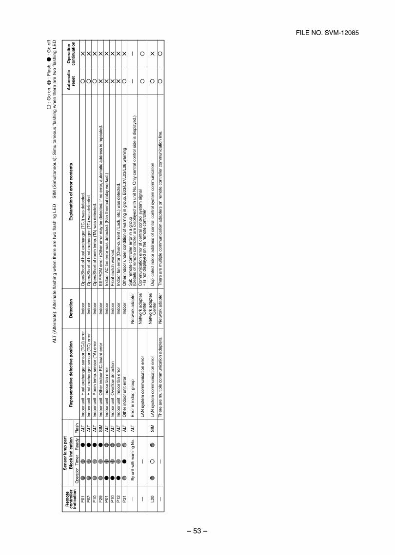
– 53 –
FILE NO. SVM-12085
: G
o on
, :
Fla
sh,
: G
o of
fA
LT (
Alte
rnat
e): A
ltern
ate
flash
ing
whe
n th
ere
are
two
flash
ing
LED
SIM
(S
imul
tane
ous)
: Sim
ulta
neou
s fla
shin
g w
hen
ther
e ar
e t
wo
flash
ing
LED
Rem
ote
con
tro
ller
ind
icat
ion
F01
F02
F10
F29
P01
P10
P12
P31 — — L20
—
Sen
sor
lam
p p
art
Blo
ck in
dic
atio
n O
pera
tion
Tim
er R
eady
Fla
shA
LTA
LTA
LTS
IMA
LTA
LTA
LTA
LT
By
unit
with
war
ning
No.
ALT
—
SIM
—
Rep
rese
nta
tive
def
ecti
ve p
osi
tio
n
Indo
or u
nit
Hea
t exc
hang
er s
enso
r (T
CJ)
err
orIn
door
uni
t H
eat e
xcha
nger
sen
sor
(TC
) er
ror
Indo
or u
nit
Roo
m te
mp.
sen
sor
(TA
) er
ror
Indo
or u
nit
Oth
er in
door
P.C
. boa
rd e
rror
Indo
or u
nit
Indo
or fa
n er
ror
Indo
or u
nit
Ove
rflo
w d
etec
tion
Indo
or u
nit
Indo
or fa
n er
ror
Oth
er in
door
uni
t err
or
Err
or in
indo
or g
roup
LAN
sys
tem
com
mun
icat
ion
erro
r
LAN
sys
tem
com
mun
icat
ion
erro
r
The
re a
re m
ultip
le c
omm
unic
atio
n ad
apte
rs.
Det
ecti
on
Indo
orIn
door
Indo
orIn
door
Indo
orIn
door
Indo
orIn
door
Net
wor
k ad
apte
r
Net
wor
k ad
apte
r/C
ente
rN
etw
ork
adap
ter/
Cen
ter
Net
wor
k ad
apte
r
Exp
lan
atio
n o
f err
or
con
ten
ts
Ope
n/S
hort
of h
eat e
xcha
nger
(T
CJ)
was
det
ecte
d.O
pen/
Sho
rt o
f hea
t exc
hang
er (
TC
) w
as d
etec
ted.
Ope
n/S
hort
of r
oom
tem
p. (
TA)
was
det
ecte
d.E
EP
RO
M e
rror
(O
ther
err
or m
ay b
e de
tect
ed. I
f no
erro
r, au
tom
atic
add
ress
is r
epea
ted.
Indo
or A
C fa
n er
ror
was
det
ecte
d. (
Fan
ther
mal
rel
ay w
orke
d.)
Flo
at s
witc
h w
orke
d.In
door
fan
erro
r (O
ver-
curr
ent /
Loc
k, e
tc.)
was
det
ecte
d.O
ther
indo
or u
nder
con
ditio
n of
war
ning
in g
roup
. E03
/L07
/L03
/L08
war
ning
Sub
rem
ote
cont
rolle
r er
ror
in a
gro
up(D
etai
ls o
f rem
ote
cont
rolle
r ar
e di
spla
yed
with
uni
t No.
Onl
y ce
ntra
l con
trol
sid
e is
dis
play
ed.)
Com
mun
icat
ion
erro
r of
cen
tral
con
trol
sys
tem
sig
nal
∗ Is
not
dis
play
ed o
n th
e re
mot
e co
ntro
ller
Dup
licat
ed in
door
add
ress
of c
entr
al c
ontr
ol s
yste
m c
omm
unic
atio
n
The
re a
re m
ultip
le c
omm
unic
atio
n ad
apte
rs o
n re
mot
e co
ntro
ller
com
mun
icat
ion
line.
Au
tom
atic
Op
erat
ion
rese
tco
ntin
uatio
n
× × ××
××
××
××
× ×—
— ×
SVM-12085_051-114.indd 53SVM-12085_051-114.indd 53 12/06/12 11:15 AM12/06/12 11:15 AM
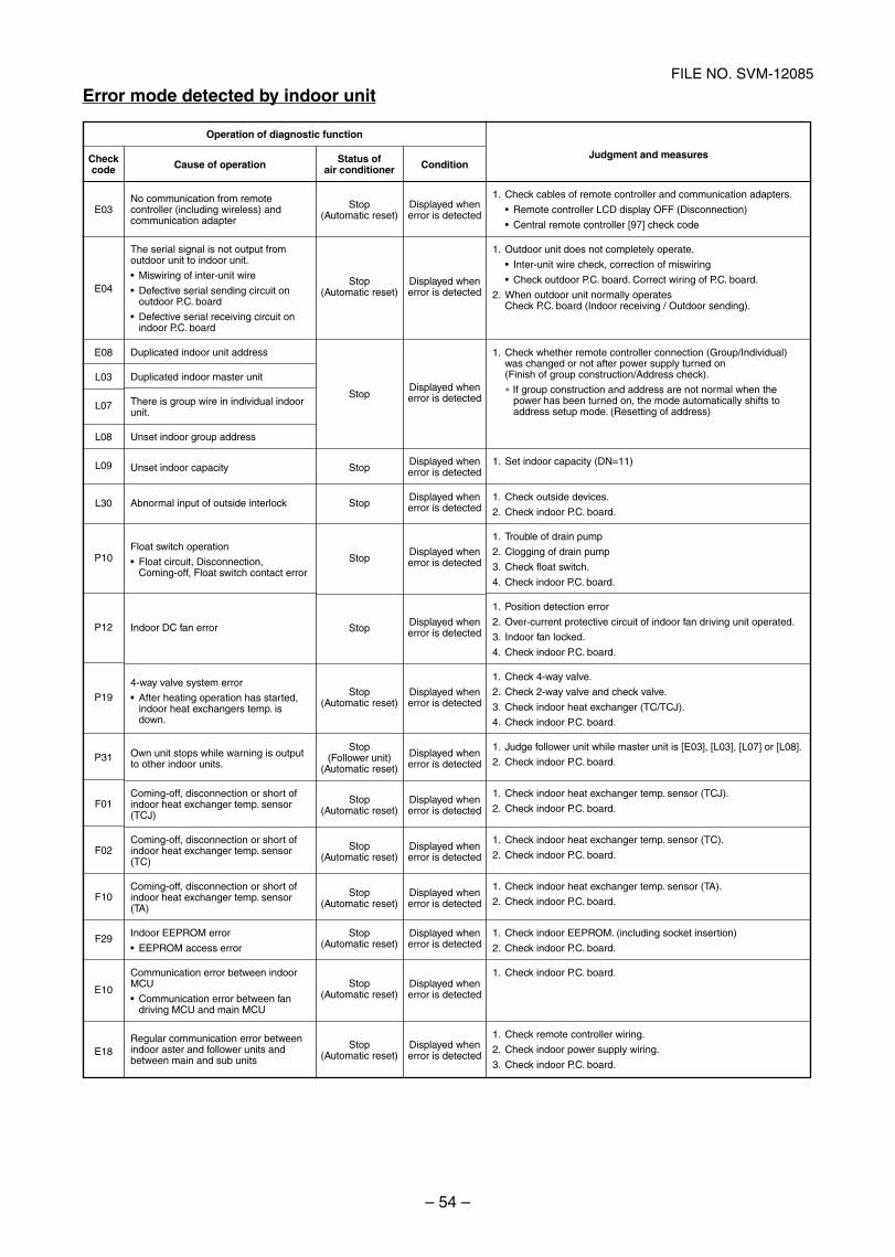
– 54 –
FILE NO. SVM-12085
Error mode detected by indoor unit
Operation of diagnostic function
Checkcode
E03
E04
E08
L03
L07
L08
L09
L30
P10
P12
P19
P31
F01
F02
F10
F29
E10
E18
Cause of operation
No communication from remotecontroller (including wireless) andcommunication adapter
The serial signal is not output fromoutdoor unit to indoor unit.
Miswiring of inter-unit wire
Defective serial sending circuit onoutdoor P.C. board
Defective serial receiving circuit onindoor P.C. board
Duplicated indoor unit address
Duplicated indoor master unit
There is group wire in individual indoorunit.
Unset indoor group address
Unset indoor capacity
Abnormal input of outside interlock
Float switch operation
Float circuit, Disconnection,Coming-off, Float switch contact error
Indoor DC fan error
4-way valve system error
After heating operation has started,indoor heat exchangers temp. isdown.
Own unit stops while warning is outputto other indoor units.
Coming-off, disconnection or short ofindoor heat exchanger temp. sensor(TCJ)
Coming-off, disconnection or short ofindoor heat exchanger temp. sensor(TC)
Coming-off, disconnection or short ofindoor heat exchanger temp. sensor(TA)
Indoor EEPROM error
EEPROM access error
Communication error between indoorMCU
Communication error between fandriving MCU and main MCU
Regular communication error betweenindoor aster and follower units andbetween main and sub units
Status ofair conditioner
Stop(Automatic reset)
Stop(Automatic reset)
Stop
Stop
Stop
Stop
Stop
Stop(Automatic reset)
Stop(Follower unit)
(Automatic reset)
Stop(Automatic reset)
Stop(Automatic reset)
Stop(Automatic reset)
Stop(Automatic reset)
Stop(Automatic reset)
Stop(Automatic reset)
Condition
Displayed whenerror is detected
Displayed whenerror is detected
Displayed whenerror is detected
Displayed whenerror is detected
Displayed whenerror is detected
Displayed whenerror is detected
Displayed whenerror is detected
Displayed whenerror is detected
Displayed whenerror is detected
Displayed whenerror is detected
Displayed whenerror is detected
Displayed whenerror is detected
Displayed whenerror is detected
Displayed whenerror is detected
Displayed whenerror is detected
Judgment and measures
1. Check cables of remote controller and communication adapters.
Remote controller LCD display OFF (Disconnection)
Central remote controller [97] check code
1. Outdoor unit does not completely operate.
Inter-unit wire check, correction of miswiring
Check outdoor P.C. board. Correct wiring of P.C. board.
2. When outdoor unit normally operatesCheck P.C. board (Indoor receiving / Outdoor sending).
1. Check whether remote controller connection (Group/Individual)was changed or not after power supply turned on(Finish of group construction/Address check).
∗ If group construction and address are not normal when thepower has been turned on, the mode automatically shifts toaddress setup mode. (Resetting of address)
1. Set indoor capacity (DN=11)
1. Check outside devices.
2. Check indoor P.C. board.
1. Trouble of drain pump
2. Clogging of drain pump
3. Check float switch.
4. Check indoor P.C. board.
1. Position detection error
2. Over-current protective circuit of indoor fan driving unit operated.
3. Indoor fan locked.
4. Check indoor P.C. board.
1. Check 4-way valve.
2. Check 2-way valve and check valve.
3. Check indoor heat exchanger (TC/TCJ).
4. Check indoor P.C. board.
1. Judge follower unit while master unit is [E03], [L03], [L07] or [L08].
2. Check indoor P.C. board.
1. Check indoor heat exchanger temp. sensor (TCJ).
2. Check indoor P.C. board.
1. Check indoor heat exchanger temp. sensor (TC).
2. Check indoor P.C. board.
1. Check indoor heat exchanger temp. sensor (TA).
2. Check indoor P.C. board.
1. Check indoor EEPROM. (including socket insertion)
2. Check indoor P.C. board.
1. Check indoor P.C. board.
1. Check remote controller wiring.
2. Check indoor power supply wiring.
3. Check indoor P.C. board.
SVM-12085_051-114.indd 54SVM-12085_051-114.indd 54 12/06/12 11:15 AM12/06/12 11:15 AM
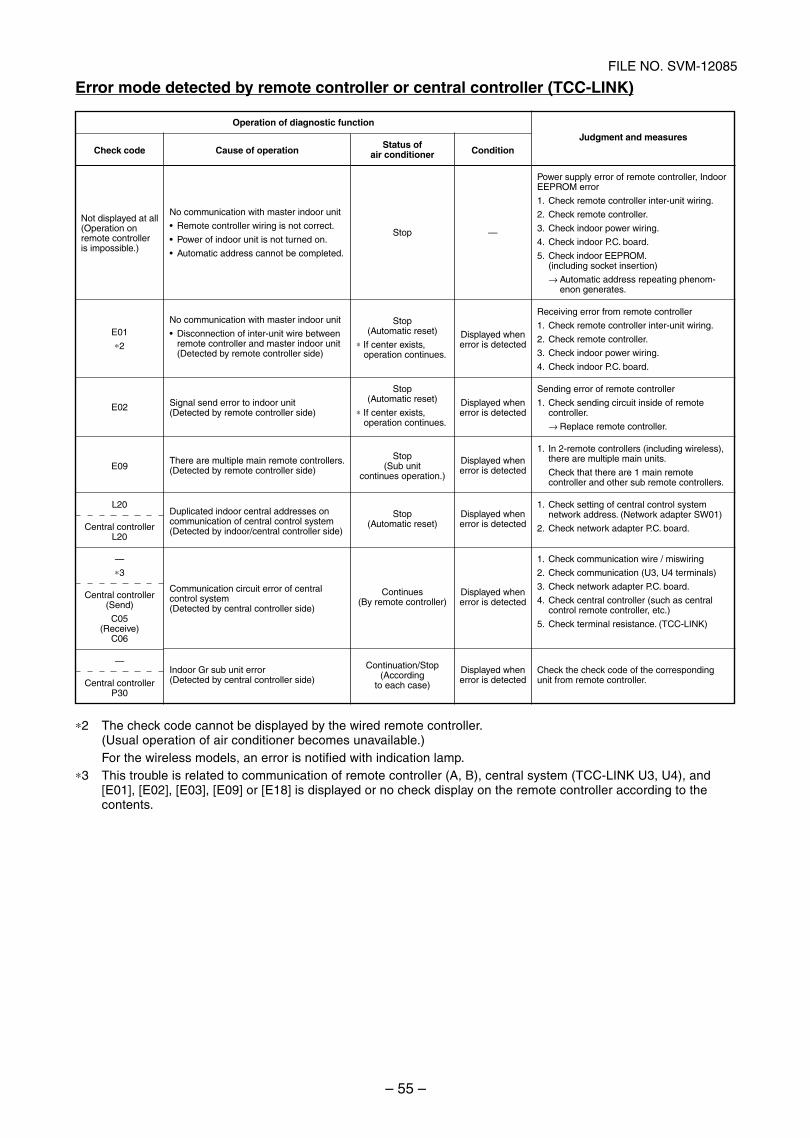
– 55 –
FILE NO. SVM-12085
Error mode detected by remote controller or central controller (TCC-LINK)
∗2 The check code cannot be displayed by the wired remote controller.(Usual operation of air conditioner becomes unavailable.)For the wireless models, an error is notified with indication lamp.
∗3 This trouble is related to communication of remote controller (A, B), central system (TCC-LINK U3, U4), and[E01], [E02], [E03], [E09] or [E18] is displayed or no check display on the remote controller according to thecontents.
Operation of diagnostic function
Check code
Not displayed at all(Operation onremote controlleris impossible.)
E01
∗2
E02
E09
L20
Central controllerL20
—
∗3
Central controller(Send)
C05(Receive)
C06
—
Central controllerP30
Cause of operation
No communication with master indoor unit
Remote controller wiring is not correct.
Power of indoor unit is not turned on.
Automatic address cannot be completed.
No communication with master indoor unit
Disconnection of inter-unit wire betweenremote controller and master indoor unit(Detected by remote controller side)
Signal send error to indoor unit(Detected by remote controller side)
There are multiple main remote controllers.(Detected by remote controller side)
Duplicated indoor central addresses oncommunication of central control system(Detected by indoor/central controller side)
Communication circuit error of centralcontrol system(Detected by central controller side)
Indoor Gr sub unit error(Detected by central controller side)
Status ofair conditioner
Stop
Stop(Automatic reset)
∗ If center exists,operation continues.
Stop(Automatic reset)
∗ If center exists,operation continues.
Stop(Sub unit
continues operation.)
Stop(Automatic reset)
Continues(By remote controller)
Continuation/Stop(According
to each case)
Condition
—
Displayed whenerror is detected
Displayed whenerror is detected
Displayed whenerror is detected
Displayed whenerror is detected
Displayed whenerror is detected
Displayed whenerror is detected
Judgment and measures
Power supply error of remote controller, IndoorEEPROM error
1. Check remote controller inter-unit wiring.
2. Check remote controller.
3. Check indoor power wiring.
4. Check indoor P.C. board.
5. Check indoor EEPROM.(including socket insertion)
→ Automatic address repeating phenom-enon generates.
Receiving error from remote controller
1. Check remote controller inter-unit wiring.
2. Check remote controller.
3. Check indoor power wiring.
4. Check indoor P.C. board.
Sending error of remote controller
1. Check sending circuit inside of remotecontroller.
→ Replace remote controller.
1. In 2-remote controllers (including wireless),there are multiple main units.
Check that there are 1 main remotecontroller and other sub remote controllers.
1. Check setting of central control systemnetwork address. (Network adapter SW01)
2. Check network adapter P.C. board.
1. Check communication wire / miswiring
2. Check communication (U3, U4 terminals)
3. Check network adapter P.C. board.
4. Check central controller (such as centralcontrol remote controller, etc.)
5. Check terminal resistance. (TCC-LINK)
Check the check code of the correspondingunit from remote controller.
SVM-12085_051-114.indd 55SVM-12085_051-114.indd 55 12/06/12 11:15 AM12/06/12 11:15 AM
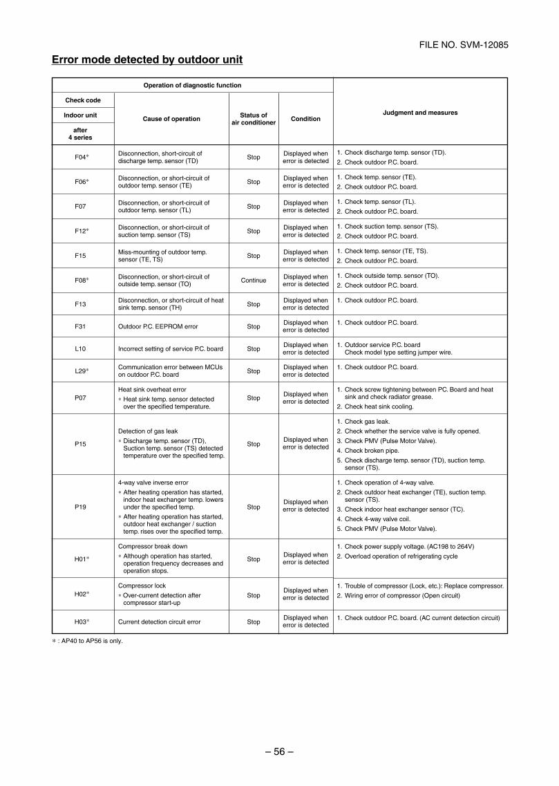
– 56 –
FILE NO. SVM-12085
Error mode detected by outdoor unit
Operation of diagnostic function
Check code
Indoor unit
after4 series
F04∗
F06∗
F07
F12∗
F15
F08∗
F13
F31
L10
L29∗
P07
P15
P19
H01∗
H02∗
H03∗
Cause of operation
Disconnection, short-circuit ofdischarge temp. sensor (TD)
Disconnection, or short-circuit ofoutdoor temp. sensor (TE)
Disconnection, or short-circuit ofoutdoor temp. sensor (TL)
Disconnection, or short-circuit ofsuction temp. sensor (TS)
Miss-mounting of outdoor temp.sensor (TE, TS)
Disconnection, or short-circuit ofoutside temp. sensor (TO)
Disconnection, or short-circuit of heatsink temp. sensor (TH)
Outdoor P.C. EEPROM error
Incorrect setting of service P.C. board
Communication error between MCUson outdoor P.C. board
Heat sink overheat error
∗ Heat sink temp. sensor detectedover the specified temperature.
Detection of gas leak
∗ Discharge temp. sensor (TD),Suction temp. sensor (TS) detectedtemperature over the specified temp.
4-way valve inverse error
∗ After heating operation has started,indoor heat exchanger temp. lowersunder the specified temp.
∗ After heating operation has started,outdoor heat exchanger / suctiontemp. rises over the specified temp.
Compressor break down
∗ Although operation has started,operation frequency decreases andoperation stops.
Compressor lock
∗ Over-current detection aftercompressor start-up
Current detection circuit error
∗ : AP40 to AP56 is only.
Status ofair conditioner
Stop
Stop
Stop
Stop
Stop
Continue
Stop
Stop
Stop
Stop
Stop
Stop
Stop
Stop
Stop
Stop
Condition
Displayed whenerror is detected
Displayed whenerror is detected
Displayed whenerror is detected
Displayed whenerror is detected
Displayed whenerror is detected
Displayed whenerror is detected
Displayed whenerror is detected
Displayed whenerror is detected
Displayed whenerror is detected
Displayed whenerror is detected
Displayed whenerror is detected
Displayed whenerror is detected
Displayed whenerror is detected
Displayed whenerror is detected
Displayed whenerror is detected
Displayed whenerror is detected
Judgment and measures
1. Check discharge temp. sensor (TD).
2. Check outdoor P.C. board.
1. Check temp. sensor (TE).
2. Check outdoor P.C. board.
1. Check temp. sensor (TL).
2. Check outdoor P.C. board.
1. Check suction temp. sensor (TS).
2. Check outdoor P.C. board.
1. Check temp. sensor (TE, TS).
2. Check outdoor P.C. board.
1. Check outside temp. sensor (TO).
2. Check outdoor P.C. board.
1. Check outdoor P.C. board.
1. Check outdoor P.C. board.
1. Outdoor service P.C. boardCheck model type setting jumper wire.
1. Check outdoor P.C. board.
1. Check screw tightening between PC. Board and heatsink and check radiator grease.
2. Check heat sink cooling.
1. Check gas leak.
2. Check whether the service valve is fully opened.
3. Check PMV (Pulse Motor Valve).
4. Check broken pipe.
5. Check discharge temp. sensor (TD), suction temp.sensor (TS).
1. Check operation of 4-way valve.
2. Check outdoor heat exchanger (TE), suction temp.sensor (TS).
3. Check indoor heat exchanger sensor (TC).
4. Check 4-way valve coil.
5. Check PMV (Pulse Motor Valve).
1. Check power supply voltage. (AC198 to 264V)
2. Overload operation of refrigerating cycle
1. Trouble of compressor (Lock, etc.): Replace compressor.
2. Wiring error of compressor (Open circuit)
1. Check outdoor P.C. board. (AC current detection circuit)
SVM-12085_051-114.indd 56SVM-12085_051-114.indd 56 12/06/12 11:15 AM12/06/12 11:15 AM
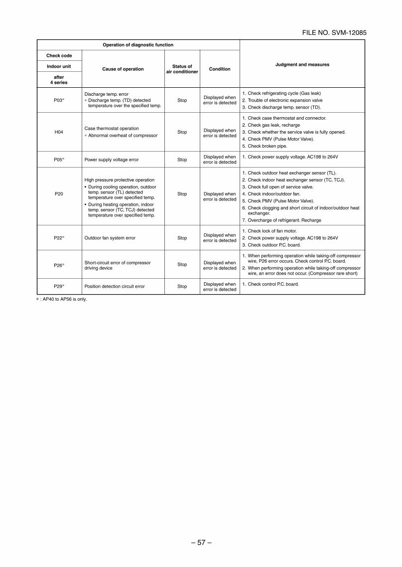
– 57 –
FILE NO. SVM-12085
Operation of diagnostic function
Check code
Indoor unit
after4 series
P03∗
H04
P05∗
P20
P22∗
P26∗
P29∗
Cause of operation
Discharge temp. error∗ Discharge temp. (TD) detected
temperature over the specified temp.
Case thermostat operation
∗ Abnormal overheat of compressor
Power supply voltage error
High pressure protective operation
During cooling operation, outdoortemp. sensor (TL) detectedtemperature over specified temp.
During heating operation, indoortemp. sensor (TC, TCJ) detectedtemperature over specified temp.
Outdoor fan system error
Short-circuit error of compressordriving device
Position detection circuit error
Status ofair conditioner
Stop
Stop
Stop
Stop
Stop
Stop
Stop
Condition
Displayed whenerror is detected
Displayed whenerror is detected
Displayed whenerror is detected
Displayed whenerror is detected
Displayed whenerror is detected
Displayed whenerror is detected
Displayed whenerror is detected
Judgment and measures
1. Check refrigerating cycle (Gas leak)
2. Trouble of electronic expansion valve
3. Check discharge temp. sensor (TD).
1. Check case thermostat and connector.
2. Check gas leak, recharge
3. Check whether the service valve is fully opened.
4. Check PMV (Pulse Motor Valve).
5. Check broken pipe.
1. Check power supply voltage. AC198 to 264V
1. Check outdoor heat exchanger sensor (TL).
2. Check indoor heat exchanger sensor (TC, TCJ).
3. Check full open of service valve.
4. Check indoor/outdoor fan.
5. Check PMV (Pulse Motor Valve).
6. Check clogging and short circuit of indoor/outdoor heatexchanger.
7. Overcharge of refrigerant. Recharge
1. Check lock of fan motor.
2. Check power supply voltage. AC198 to 264V
3. Check outdoor P.C. board.
1. When performing operation while taking-off compressorwire, P26 error occurs. Check control P.C. board.
2. When performing operation while taking-off compressorwire, an error does not occur. (Compressor rare short)
1. Check control P.C. board.
∗ : AP40 to AP56 is only.
SVM-12085_051-114.indd 57SVM-12085_051-114.indd 57 12/06/12 11:15 AM12/06/12 11:15 AM
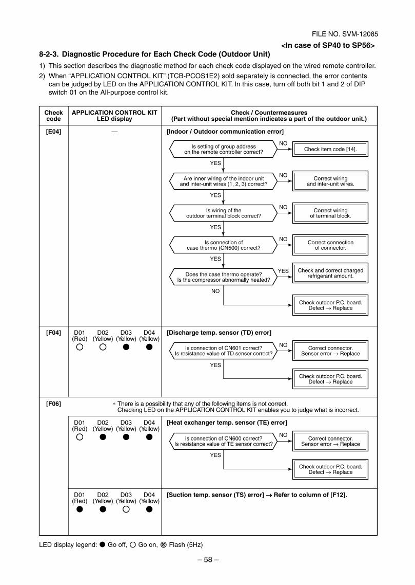
– 58 –
FILE NO. SVM-12085
Is setting of group addresson the remote controller correct?
Check outdoor P.C. board.Defect → Replace
Is connection of CN601 correct?Is resistance value of TD sensor correct?
Correct connector.Sensor error → Replace
Check outdoor P.C. board.Defect → Replace
Is connection of CN600 correct?Is resistance value of TE sensor correct?
Correct connector.Sensor error → Replace
Check outdoor P.C. board.Defect → Replace
Are inner wiring of the indoor unitand inter-unit wires (1, 2, 3) correct?
Is wiring of theoutdoor terminal block correct?
Correct wiringand inter-unit wires.
Check item code [14].
Is connection ofcase thermo (CN500) correct?
Correct wiringof terminal block.
Does the case thermo operate?Is the compressor abnormally heated?
Correct connectionof connector.
Check and correct chargedrefrigerant amount.
YES
YES
YES
YES
NO
NO
NO
NO
NO
YES
YES
NO
YES
NO
8-2-3. Diagnostic Procedure for Each Check Code (Outdoor Unit)
1) This section describes the diagnostic method for each check code displayed on the wired remote controller.
2) When “APPLICATION CONTROL KIT” (TCB-PCOS1E2) sold separately is connected, the error contentscan be judged by LED on the APPLICATION CONTROL KIT. In this case, turn off both bit 1 and 2 of DIPswitch 01 on the All-purpose control kit.
Checkcode
[E04]
APPLICATION CONTROL KITLED display
—
Check / Countermeasures(Part without special mention indicates a part of the outdoor unit.)
[Indoor / Outdoor communication error]
[F04]
[F06]
D01 D02 D03 D04(Red) (Yellow) (Yellow) (Yellow)
D01 D02 D03 D04(Red) (Yellow) (Yellow) (Yellow)
D01 D02 D03 D04(Red) (Yellow) (Yellow) (Yellow)
[Discharge temp. sensor (TD) error]
∗ There is a possibility that any of the following items is not correct.Checking LED on the APPLICATION CONTROL KIT enables you to judge what is incorrect.
[Suction temp. sensor (TS) error] →→→→→ Refer to column of [F12].
LED display legend: Go off, Go on, Flash (5Hz)
<In case of SP40 to SP56>
[Heat exchanger temp. sensor (TE) error]
SVM-12085_051-114.indd 58SVM-12085_051-114.indd 58 12/06/12 11:15 AM12/06/12 11:15 AM
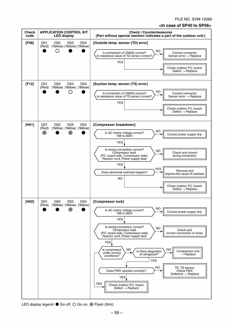
– 59 –
FILE NO. SVM-12085
Compressor lock→ Replace
Correct power supply line.
Correct power supply line.
Does abnormal overload happen?
Does PMV operate correctly?
Check outdoor P.C. board.Defect → Replace
Is AC mains voltage correct?198 to 264V
Is AC mains voltage correct?198 to 264V
Is there stagnationof refrigerant?
Is compressorunder correctconditions?
Check and correct connection of wires.
Remove andimprove the cause of overload.
Check outdoor P.C. board.Defect → Replace
Check and correctwiring connection.
Is connection of CN603 correct?Is resistance value of TS sensor correct?
Correct connector.Sensor error → Replace
Check outdoor P.C. board.Defect → Replace
Is connection of CN602 correct?Is resistance value of TO sensor correct?
Correct connector.Sensor error → Replace
Check outdoor P.C. board.Defect → Replace
TE, TS sensor,Check PMV.
Defective → Replace
Is wiring connection correct?Compressor lead
(P.C. board side, Compressor side) Reactor cord, Power supply lead
Is wiring connection correct?Compressor lead
(P.C. board side, Compressor side)Reactor cord, Power supply lead
YES
NO
YES
NO
YES
YES
YES
YES
YES
YES
YES
NO
NO
NO
YES
NO
NO
NONO
NO
Checkcode
[F08]
APPLICATION CONTROL KITLED display
D01 D02 D03 D04(Red) (Yellow) (Yellow) (Yellow)
Check / Countermeasures(Part without special mention indicates a part of the outdoor unit.)
[Outside temp. sensor (TO) error]
[Suction temp. sensor (TS) error]
[Compressor breakdown]
[Compressor lock]
D01 D02 D03 D04(Red) (Yellow) (Yellow) (Yellow)
D01 D02 D03 D04(Red) (Yellow) (Yellow) (Yellow)
D01 D02 D03 D04(Red) (Yellow) (Yellow) (Yellow)
[F12]
[H01]
[H02]
LED display legend: Go off, Go on, Flash (5Hz)
<In case of SP40 to SP56>
SVM-12085_051-114.indd 59SVM-12085_051-114.indd 59 12/06/12 11:15 AM12/06/12 11:15 AM
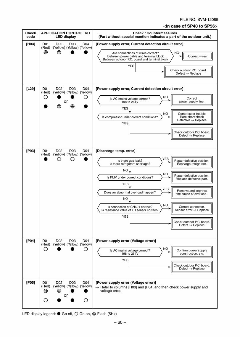
– 60 –
FILE NO. SVM-12085
Is PMV under correct conditions?
Is compressor under correct conditions?
Is AC mains voltage correct?198 to 264V
Is connection of CN601 correct?Is resistance value of TD sensor correct?
Is there gas leak?Is there refrigerant shortage?
Is AC mains voltage correct?198 to 264V
Correct wires
Check outdoor P.C. board.Defect → Replace
Are connections of wires correct?Between power cable and terminal block
Between outdoor P.C. board and terminal block
Correctpower supply line.
Compressor troubleRare short check
Defective → Replace
Check outdoor P.C. board.Defect → Replace
Repair defective position.Recharge refrigerant.
Repair defective position.Replace defective part.
Does an abnormal overload happen? Remove and improvethe cause of overload.
Correct connector.Sensor error → Replace
Check outdoor P.C. board.Defect → Replace
Confirm power supplyconstruction, etc.
Check outdoor P.C. board.Defect → Replace
YES
YES
YES
YES
NO
YES
NO
YES
NO
NO
NO
YES
NO
YES
NO
NO
Checkcode
[H03]
APPLICATION CONTROL KITLED display
D01 D02 D03 D04(Red) (Yellow) (Yellow) (Yellow)
Check / Countermeasures(Part without special mention indicates a part of the outdoor unit.)
[Power supply error, Current detection circuit error]
[Power supply error, Current detection circuit error]
[Discharge temp. error]
[Power supply error (Voltage error)]
[Power supply error (Voltage error)]→ Refer to columns [H03] and [P04] and then check power supply and
voltage error.
LED display legend: Go off, Go on, Flash (5Hz)
D01 D02 D03 D04(Red) (Yellow) (Yellow) (Yellow)
or
D01 D02 D03 D04(Red) (Yellow) (Yellow) (Yellow)
D01 D02 D03 D04(Red) (Yellow) (Yellow) (Yellow)
D01 D02 D03 D04(Red) (Yellow) (Yellow) (Yellow)
or
[L29]
[P03]
[P04]
[P05]
<In case of SP40 to SP56>
SVM-12085_051-114.indd 60SVM-12085_051-114.indd 60 12/06/12 11:15 AM12/06/12 11:15 AM
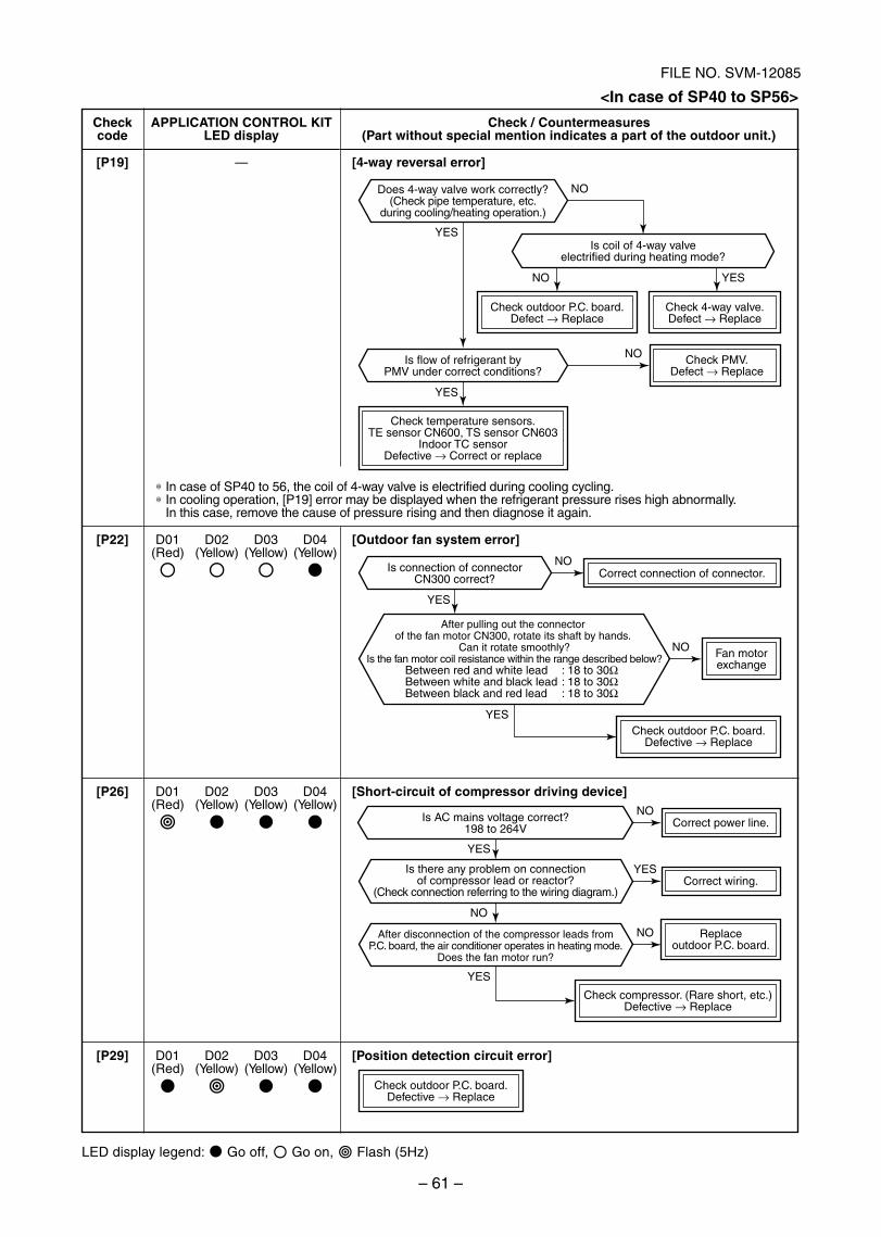
– 61 –
FILE NO. SVM-12085
Is AC mains voltage correct?198 to 264V
After disconnection of the compressor leads fromP.C. board, the air conditioner operates in heating mode.
Does the fan motor run?
Is connection of connectorCN300 correct?
Is flow of refrigerant byPMV under correct conditions?
Is coil of 4-way valveelectrified during heating mode?
Is there any problem on connectionof compressor lead or reactor?
(Check connection referring to the wiring diagram.)
Does 4-way valve work correctly?(Check pipe temperature, etc.
during cooling/heating operation.)
Check temperature sensors.TE sensor CN600, TS sensor CN603
Indoor TC sensorDefective → Correct or replace
Correct connection of connector.
Fan motorexchange
Check outdoor P.C. board.Defect → Replace
Check 4-way valve.Defect → Replace
Check PMV.Defect → Replace
Check outdoor P.C. board.Defective → Replace
Check outdoor P.C. board.Defective → Replace
Replaceoutdoor P.C. board.
Check compressor. (Rare short, etc.)Defective → Replace
Correct power line.
Correct wiring.
YES
NO
YES
YES
YES
YES
NO
YES
NO
NO
NO
NO
NO
YES
YES
NO
After pulling out the connector of the fan motor CN300, rotate its shaft by hands.
Can it rotate smoothly?Is the fan motor coil resistance within the range described below?
Between red and white lead : 18 to 30ΩBetween white and black lead : 18 to 30ΩBetween black and red lead : 18 to 30Ω
Checkcode
[P19]
APPLICATION CONTROL KITLED display
—
Check / Countermeasures(Part without special mention indicates a part of the outdoor unit.)
[4-way reversal error]
[P22]
[P26]
[P29]
D01 D02 D03 D04(Red) (Yellow) (Yellow) (Yellow)
D01 D02 D03 D04(Red) (Yellow) (Yellow) (Yellow)
D01 D02 D03 D04(Red) (Yellow) (Yellow) (Yellow)
∗ In case of SP40 to 56, the coil of 4-way valve is electrified during cooling cycling.∗ In cooling operation, [P19] error may be displayed when the refrigerant pressure rises high abnormally.
In this case, remove the cause of pressure rising and then diagnose it again.
[Outdoor fan system error]
[Short-circuit of compressor driving device]
[Position detection circuit error]
LED display legend: Go off, Go on, Flash (5Hz)
<In case of SP40 to SP56>
SVM-12085_051-114.indd 61SVM-12085_051-114.indd 61 12/06/12 11:15 AM12/06/12 11:15 AM
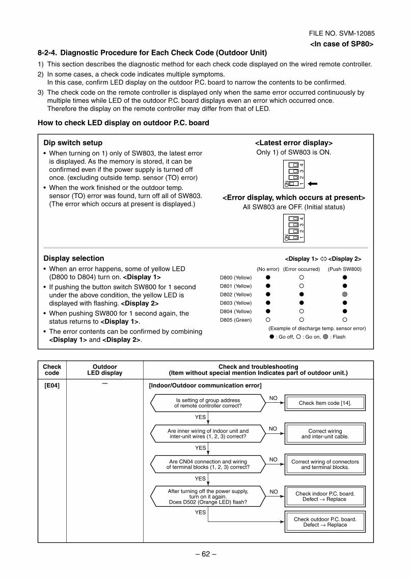
– 62 –
FILE NO. SVM-12085
Check Item code [14].
Correct wiring of connectorsand terminal blocks.
Check indoor P.C. board.Defect → Replace
Check outdoor P.C. board.Defect → Replace
Correct wiringand inter-unit cable.
Is setting of group addressof remote controller correct?
Are inner wiring of indoor unit andinter-unit wires (1, 2, 3) correct?
Are CN04 connection and wiringof terminal blocks (1, 2, 3) correct?
After turning off the power supply,turn on it again.
Does D502 (Orange LED) flash?
YES
YES
YES
YES
NO
NO
NO
NO
<In case of SP80>8-2-4. Diagnostic Procedure for Each Check Code (Outdoor Unit)
1) This section describes the diagnostic method for each check code displayed on the wired remote controller.
2) In some cases, a check code indicates multiple symptoms.In this case, confirm LED display on the outdoor P.C. board to narrow the contents to be confirmed.
3) The check code on the remote controller is displayed only when the same error occurred continuously bymultiple times while LED of the outdoor P.C. board displays even an error which occurred once.Therefore the display on the remote controller may differ from that of LED.
How to check LED display on outdoor P.C. board
Dip switch setupWhen turning on 1) only of SW803, the latest erroris displayed. As the memory is stored, it can beconfirmed even if the power supply is turned offonce. (excluding outside temp. sensor (TO) error)
When the work finished or the outdoor temp.sensor (TO) error was found, turn off all of SW803.(The error which occurs at present is displayed.)
<Latest error display>Only 1) of SW803 is ON.
<Error display, which occurs at present>All SW803 are OFF. (Initial status)
Display selectionWhen an error happens, some of yellow LED(D800 to D804) turn on. <Display 1>If pushing the button switch SW800 for 1 secondunder the above condition, the yellow LED isdisplayed with flashing. <Display 2>
When pushing SW800 for 1 second again, thestatus returns to <Display 1>.
The error contents can be confirmed by combining<Display 1> and <Display 2>.
<Display 1> <Display 2>
(No error) (Error occurred) (Push SW800)
D800 (Yellow)
D801 (Yellow)
D802 (Yellow)
D803 (Yellow)
D804 (Yellow)
D805 (Green)
(Example of discharge temp. sensor error)
: Go off, : Go on, : Flash
Checkcode
[E04]
OutdoorLED display
—
Check and troubleshooting(Item without special mention Indicates part of outdoor unit.)
[Indoor/Outdoor communication error]
ON 1
23
4
ON 1
23
4
SVM-12085_051-114.indd 62SVM-12085_051-114.indd 62 12/06/12 11:15 AM12/06/12 11:15 AM
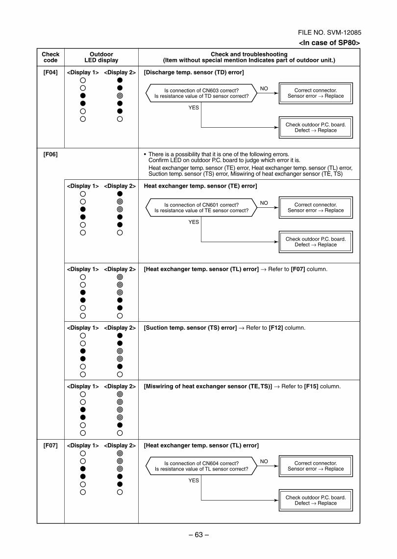
– 63 –
FILE NO. SVM-12085
Is connection of CN603 correct?Is resistance value of TD sensor correct?
Correct connector.Sensor error → Replace
Check outdoor P.C. board.Defect → Replace
YES
NO
Is connection of CN601 correct?Is resistance value of TE sensor correct?
Correct connector.Sensor error → Replace
Check outdoor P.C. board.Defect → Replace
YES
NO
Is connection of CN604 correct?Is resistance value of TL sensor correct?
Correct connector.Sensor error → Replace
Check outdoor P.C. board.Defect → Replace
YES
NO
Checkcode
[F04]
[F06]
[F07]
OutdoorLED display
<Display 1> <Display 2>
<Display 1> <Display 2>
<Display 1> <Display 2>
<Display 1> <Display 2>
<Display 1> <Display 2>
<Display 1> <Display 2>
Check and troubleshooting(Item without special mention Indicates part of outdoor unit.)
[Discharge temp. sensor (TD) error]
There is a possibility that it is one of the following errors.Confirm LED on outdoor P.C. board to judge which error it is.Heat exchanger temp. sensor (TE) error, Heat exchanger temp. sensor (TL) error,Suction temp. sensor (TS) error, Miswiring of heat exchanger sensor (TE, TS)
Heat exchanger temp. sensor (TE) error]
[Heat exchanger temp. sensor (TL) error] → Refer to [F07] column.
[Suction temp. sensor (TS) error] → Refer to [F12] column.
[Miswiring of heat exchanger sensor (TE, TS)] → Refer to [F15] column.
[Heat exchanger temp. sensor (TL) error]
<In case of SP80>
SVM-12085_051-114.indd 63SVM-12085_051-114.indd 63 12/06/12 11:15 AM12/06/12 11:15 AM
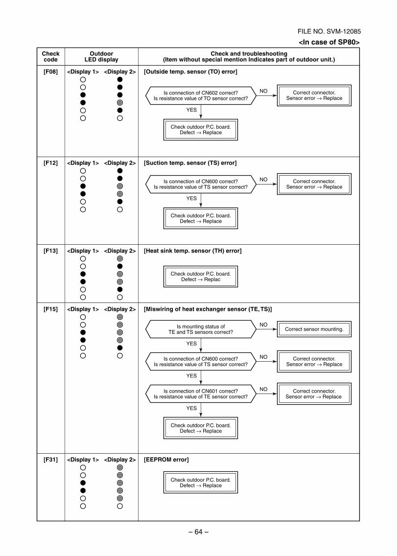
– 64 –
FILE NO. SVM-12085
Correct connector.Sensor error → Replace
Correct connector.Sensor error → Replace
Check outdoor P.C. board.Defect → Replace
Correct connector.Sensor error → Replace
Correct connector.Sensor error → Replace
Correct sensor mounting.
Check outdoor P.C. board.Defect → Replace
Check outdoor P.C. board.Defect → Replac
Check outdoor P.C. board.Defect → Replace
Check outdoor P.C. board.Defect → Replace
Is mounting status ofTE and TS sensors correct?
Is connection of CN600 correct?Is resistance value of TS sensor correct?
Is connection of CN602 correct?Is resistance value of TO sensor correct?
Is connection of CN600 correct?Is resistance value of TS sensor correct?
Is connection of CN601 correct?Is resistance value of TE sensor correct?
YES
YES
YES
YES
YES
NO
NO
NO
NO
NO
Checkcode
[F08]
[F12]
[F13]
[F15]
[F31]
OutdoorLED display
<Display 1> <Display 2>
<Display 1> <Display 2>
<Display 1> <Display 2>
<Display 1> <Display 2>
<Display 1> <Display 2>
Check and troubleshooting(Item without special mention Indicates part of outdoor unit.)
[Outside temp. sensor (TO) error]
[Suction temp. sensor (TS) error]
[Heat sink temp. sensor (TH) error]
[Miswiring of heat exchanger sensor (TE, TS)]
[EEPROM error]
<In case of SP80>
SVM-12085_051-114.indd 64SVM-12085_051-114.indd 64 12/06/12 11:15 AM12/06/12 11:15 AM
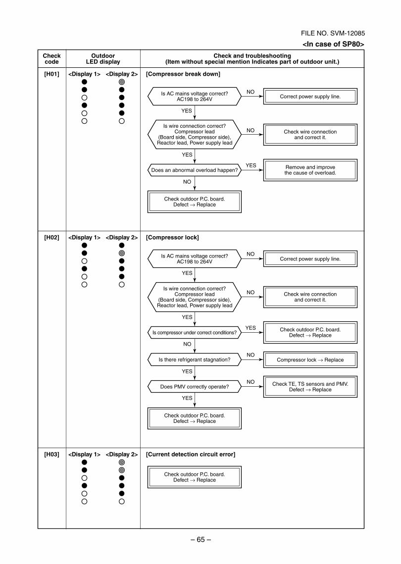
– 65 –
FILE NO. SVM-12085
Remove and improvethe cause of overload.
Check wire connectionand correct it.
Correct power supply line.
Check outdoor P.C. board.Defect → Replace
Check wire connectionand correct it.
Correct power supply line.
Is compressor under correct conditions?
Is there refrigerant stagnation?
Does PMV correctly operate?
Does an abnormal overload happen?
Is AC mains voltage correct?AC198 to 264V
Is AC mains voltage correct?AC198 to 264V
Is wire connection correct?Compressor lead
(Board side, Compressor side),Reactor lead, Power supply lead
Is wire connection correct?Compressor lead
(Board side, Compressor side),Reactor lead, Power supply lead
Compressor lock → Replace
Check outdoor P.C. board.Defect → Replace
Check TE, TS sensors and PMV.Defect → Replace
Check outdoor P.C. board.Defect → Replace
Check outdoor P.C. board.Defect → Replace
YES
YES
YES
YES
YES
YES
YES
YES
NO
NO
NO
NO
NO
NO
NO
NO
Checkcode
[H01]
[H02]
[H03]
OutdoorLED display
<Display 1> <Display 2>
<Display 1> <Display 2>
<Display 1> <Display 2>
Check and troubleshooting(Item without special mention Indicates part of outdoor unit.)
[Compressor break down]
[Compressor lock]
[Current detection circuit error]
<In case of SP80>
SVM-12085_051-114.indd 65SVM-12085_051-114.indd 65 12/06/12 11:15 AM12/06/12 11:15 AM
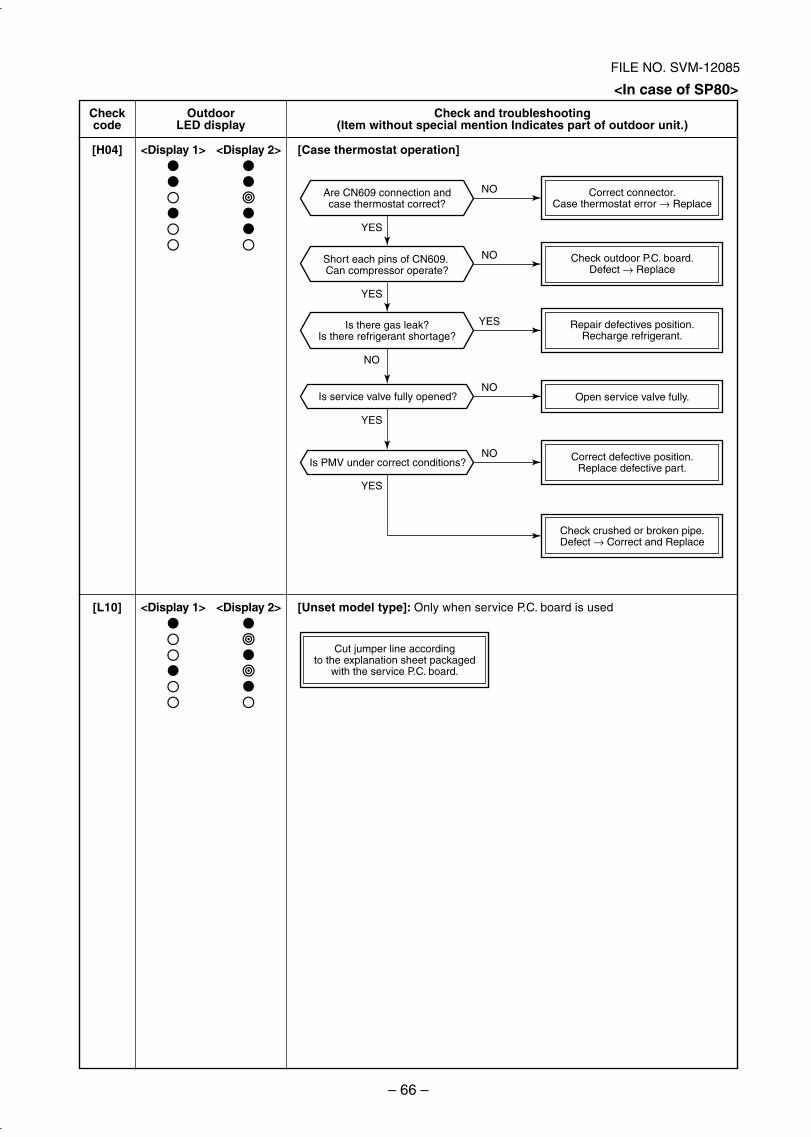
– 66 –
FILE NO. SVM-12085
Check crushed or broken pipe.Defect → Correct and Replace
Correct defective position.Replace defective part.
Open service valve fully.
Repair defectives position.Recharge refrigerant.
Check outdoor P.C. board.Defect → Replace
Correct connector.Case thermostat error → Replace
Cut jumper line accordingto the explanation sheet packaged
with the service P.C. board.
Is service valve fully opened?
Is PMV under correct conditions?
Is there gas leak?Is there refrigerant shortage?
Are CN609 connection andcase thermostat correct?
Short each pins of CN609. Can compressor operate?
YES
YES
NO
YES
YES
NO
NO
YES
NO
NO
Checkcode
[H04]
[L10]
OutdoorLED display
<Display 1> <Display 2>
<Display 1> <Display 2>
Check and troubleshooting(Item without special mention Indicates part of outdoor unit.)
[Case thermostat operation]
[Unset model type]: Only when service P.C. board is used
<In case of SP80>
SVM-12085_051-114.indd 66SVM-12085_051-114.indd 66 12/06/12 11:15 AM12/06/12 11:15 AM
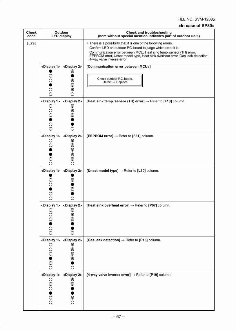
– 67 –
FILE NO. SVM-12085
Check outdoor P.C. board.Defect → Replace
Checkcode
[L29]
OutdoorLED display
<Display 1> <Display 2>
<Display 1> <Display 2>
<Display 1> <Display 2>
<Display 1> <Display 2>
<Display 1> <Display 2>
<Display 1> <Display 2>
<Display 1> <Display 2>
Check and troubleshooting(Item without special mention Indicates part of outdoor unit.)
∗ There is a possibility that it is one of the following errors.Confirm LED on outdoor P.C. board to judge which error it is.Communication error between MCU, Heat sing temp. sensor (TH) error,EEPROM error, Unset model type, Heat sink overheat error, Gas leak detection,4-way valve inverse error
[Communication error between MCUs]
[Heat sink temp. sensor (TH) error] → Refer to [F13] column.
[EEPROM error] → Refer to [F31] column.
[Unset model type] → Refer to [L10] column.
[Heat sink overheat error] → Refer to [P07] column.
[Gas leak detection] → Refer to [P15] column.
[4-way valve inverse error] → Refer to [P19] column.
<In case of SP80>
SVM-12085_051-114.indd 67SVM-12085_051-114.indd 67 12/06/12 11:15 AM12/06/12 11:15 AM
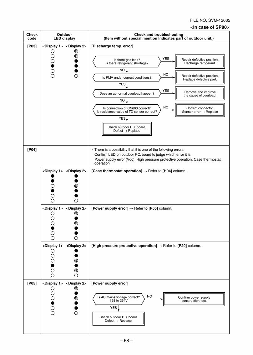
– 68 –
FILE NO. SVM-12085
Check outdoor P.C. board.Defect → Replace
Correct connector.Sensor error → Replace
Remove and improvethe cause of overload.
Repair defective position.Replace defective part.
Repair defective position.Recharge refrigerant.
Does an abnormal overload happen?
Is PMV under correct conditions?
Is connection of CN603 correct?Is resistance value of TD sensor correct?
Is there gas leak?Is there refrigerant shortage?
NO
YES
NO
YES
YES
NO
NO
YES
Confirm power supplyconstruction, etc.
Check outdoor P.C. board.Defect → Replace
Is AC mains voltage correct?198 to 264V
NO
YES
Checkcode
[P03]
[P04]
[P05]
OutdoorLED display
<Display 1> <Display 2>
<Display 1> <Display 2>
<Display 1> <Display 2>
<Display 1> <Display 2>
<Display 1> <Display 2>
Check and troubleshooting(Item without special mention Indicates part of outdoor unit.)
[Discharge temp. error]
∗ There is a possibility that it is one of the following errors.Confirm LED on outdoor P.C. board to judge which error it is.Power supply error (Vdc), High pressure protective operation, Case thermostatoperation
[Case thermostat operation] → Refer to [H04] column.
[Power supply error] → Refer to [P05] column.
[High pressure protective operation] → Refer to [P20] column.
[Power supply error]
<In case of SP80>
SVM-12085_051-114.indd 68SVM-12085_051-114.indd 68 12/06/12 11:15 AM12/06/12 11:15 AM
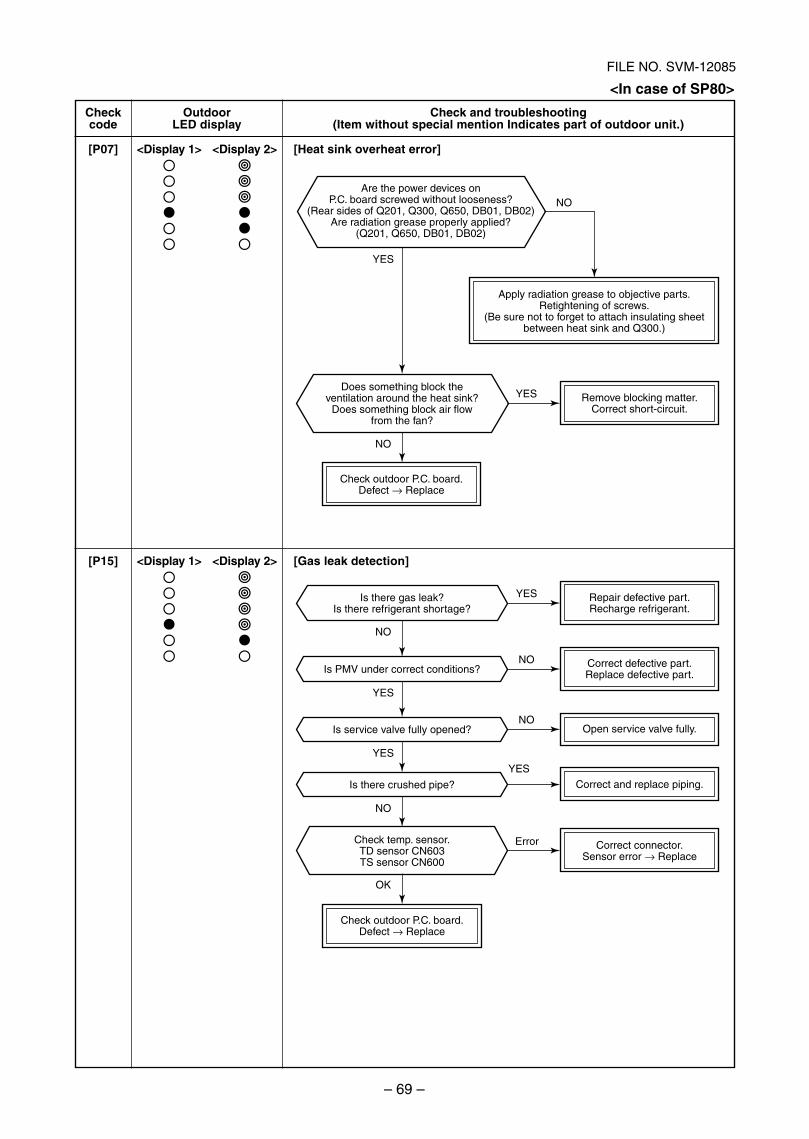
– 69 –
FILE NO. SVM-12085
Are the power devices onP.C. board screwed without looseness?
(Rear sides of Q201, Q300, Q650, DB01, DB02)Are radiation grease properly applied?
(Q201, Q650, DB01, DB02)
Check outdoor P.C. board.Defect → Replace
Remove blocking matter.Correct short-circuit.
Open service valve fully.
Correct and replace piping.
Correct connector.Sensor error → Replace
Check outdoor P.C. board.Defect → Replace
Correct defective part.Replace defective part.
Repair defective part.Recharge refrigerant.
Is there crushed pipe?
Is service valve fully opened?
Is PMV under correct conditions?
Is there gas leak?Is there refrigerant shortage?
Check temp. sensor.TD sensor CN603TS sensor CN600
Does something block theventilation around the heat sink?
Does something block air flowfrom the fan?
Apply radiation grease to objective parts.Retightening of screws.
(Be sure not to forget to attach insulating sheetbetween heat sink and Q300.)
Error
OK
NO
YES
YES
YES
YES
NO
NO
NO
NO
NO
YES
YES
Checkcode
[P07]
[P15]
OutdoorLED display
<Display 1> <Display 2>
<Display 1> <Display 2>
Check and troubleshooting(Item without special mention Indicates part of outdoor unit.)
[Heat sink overheat error]
[Gas leak detection]
<In case of SP80>
SVM-12085_051-114.indd 69SVM-12085_051-114.indd 69 12/06/12 11:15 AM12/06/12 11:15 AM
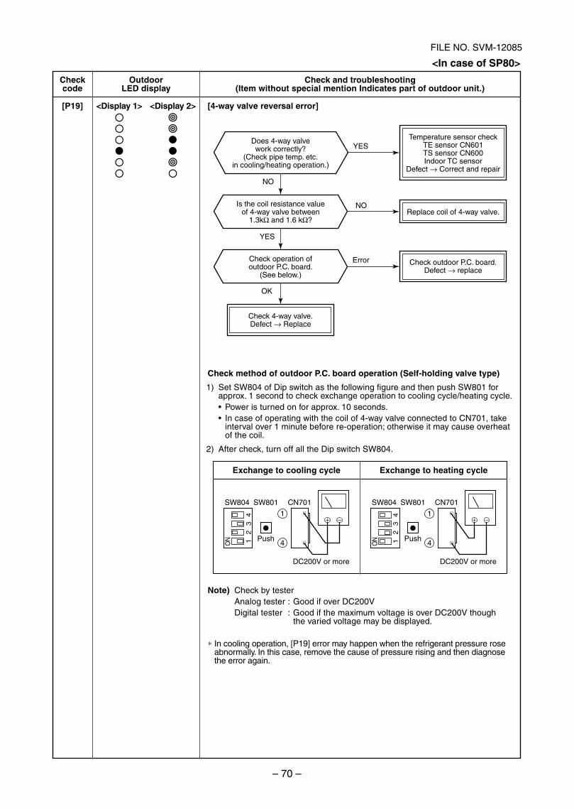
– 70 –
FILE NO. SVM-12085
ON 1
23
4
ON 1
23
4
SW804 SW801 CN701
Push
DC200V or more
1
4
SW804 SW801 CN701
Push
DC200V or more
1
4
Check outdoor P.C. board.Defect → replace
Replace coil of 4-way valve.
Temperature sensor checkTE sensor CN601TS sensor CN600Indoor TC sensor
Defect → Correct and repair
Is the coil resistance valueof 4-way valve between
1.3kΩ and 1.6 kΩ?
Check operation ofoutdoor P.C. board.
(See below.)
Does 4-way valvework correctly?
(Check pipe temp. etc.in cooling/heating operation.)
Check 4-way valve.Defect → Replace
YES
YES
NO
NO
Error
OK
Checkcode
[P19]
OutdoorLED display
<Display 1> <Display 2>
Check and troubleshooting(Item without special mention Indicates part of outdoor unit.)
[4-way valve reversal error]
Check method of outdoor P.C. board operation (Self-holding valve type)
1) Set SW804 of Dip switch as the following figure and then push SW801 forapprox. 1 second to check exchange operation to cooling cycle/heating cycle.
Power is turned on for approx. 10 seconds.In case of operating with the coil of 4-way valve connected to CN701, takeinterval over 1 minute before re-operation; otherwise it may cause overheatof the coil.
2) After check, turn off all the Dip switch SW804.
Exchange to cooling cycle Exchange to heating cycle
Note) Check by testerAnalog tester : Good if over DC200VDigital tester : Good if the maximum voltage is over DC200V though
the varied voltage may be displayed.
∗ In cooling operation, [P19] error may happen when the refrigerant pressure roseabnormally. In this case, remove the cause of pressure rising and then diagnosethe error again.
<In case of SP80>
SVM-12085_051-114.indd 70SVM-12085_051-114.indd 70 12/06/12 11:15 AM12/06/12 11:15 AM
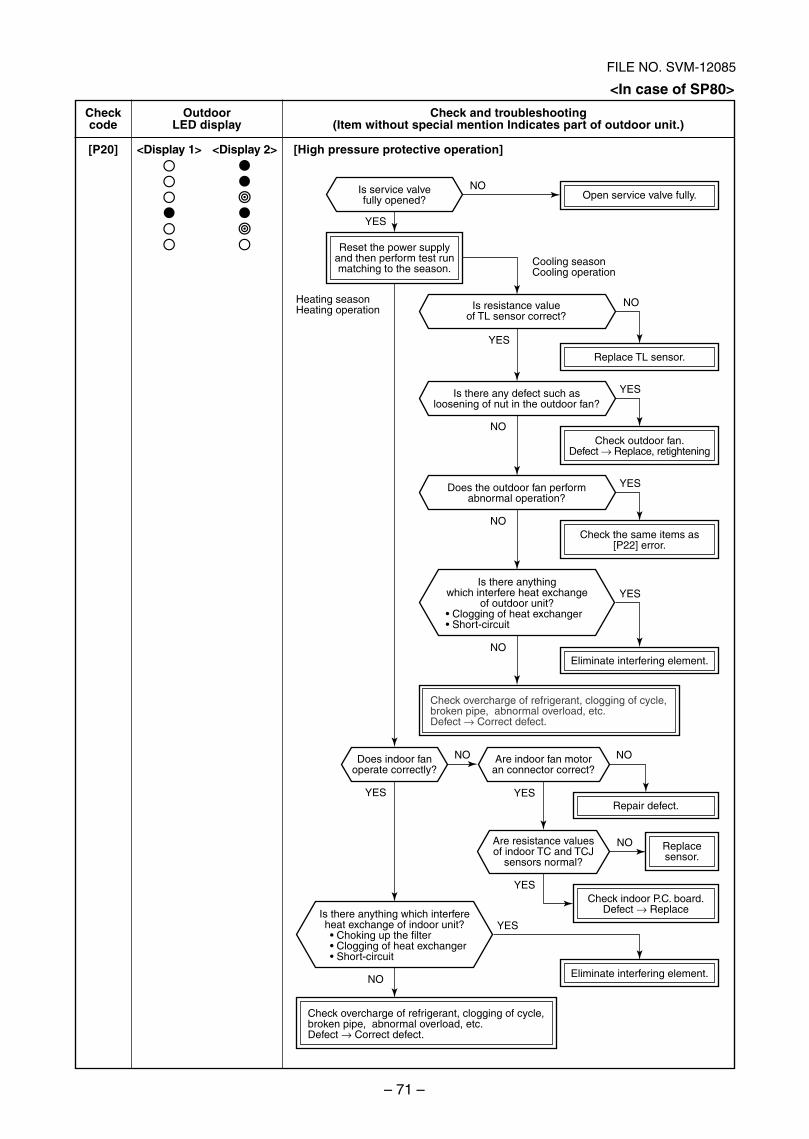
– 71 –
FILE NO. SVM-12085
Reset the power supplyand then perform test runmatching to the season.
Open service valve fully.
Check outdoor fan.Defect → Replace, retightening
Replacesensor.
Check indoor P.C. board.Defect → Replace
Repair defect.
Is service valvefully opened?
Is there any defect such asloosening of nut in the outdoor fan?
Does the outdoor fan performabnormal operation?
Does indoor fanoperate correctly?
Are indoor fan motoran connector correct?
Is resistance valueof TL sensor correct?
Are resistance valuesof indoor TC and TCJ
sensors normal?
Replace TL sensor.
Check the same items as[P22] error.
Check overcharge of refrigerant, clogging of cycle, broken pipe, abnormal overload, etc.Defect → Correct defect.
Check overcharge of refrigerant, clogging of cycle, broken pipe, abnormal overload, etc.Defect → Correct defect.
Eliminate interfering element.
Eliminate interfering element.
Heating seasonHeating operation
Cooling seasonCooling operation
Is there anythingwhich interfere heat exchange
of outdoor unit?exchanger
rt-circuit
Is there anything which interfereheat exchange of indoor unit?
exchangerrt-circuit
NO
NO
NO
NO
NO
NO
NO
NO
NO
Checkcode
[P20]
OutdoorLED display
<Display 1> <Display 2>
Check and troubleshooting(Item without special mention Indicates part of outdoor unit.)
[High pressure protective operation]
<In case of SP80>
SVM-12085_051-114.indd 71SVM-12085_051-114.indd 71 12/06/12 11:15 AM12/06/12 11:15 AM
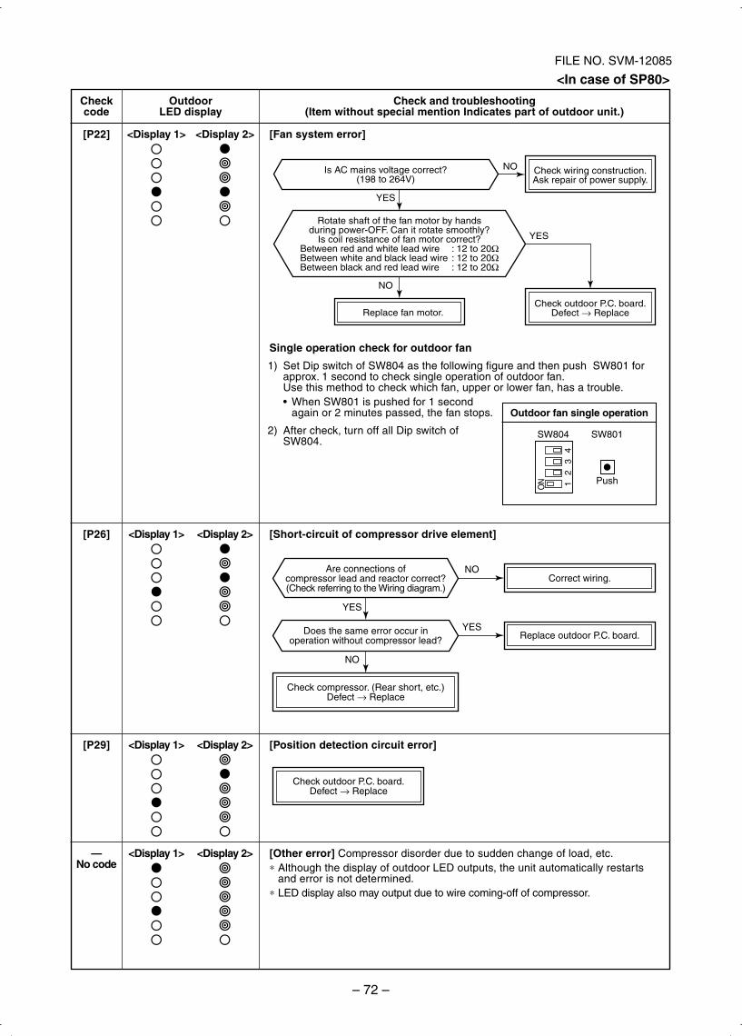
– 72 –
FILE NO. SVM-12085
Correct wiring.
Replace outdoor P.C. board.
Check outdoor P.C. board.Defect → Replace
YES
NO
Does the same error occur inoperation without compressor lead?
Check compressor. (Rear short, etc.)Defect → Replace
Are connections ofcompressor lead and reactor correct?(Check referring to the Wiring diagram.)
NO
YES
Check outdoor P.C. board.Defect → ReplaceReplace fan motor.
Check wiring construction.Ask repair of power supply.
YES
NOIs AC mains voltage correct?(198 to 264V)
Rotate shaft of the fan motor by handsduring power-OFF. Can it rotate smoothly?
Is coil resistance of fan motor correct?Between red and white lead wire : 12 to 20ΩBetween white and black lead wire : 12 to 20ΩBetween black and red lead wire : 12 to 20Ω
YES
NO
Checkcode
[P22]
[P26]
[P29]
—No code
OutdoorLED display
<Display 1> <Display 2>
<Display 1> <Display 2>
<Display 1> <Display 2>
<Display 1> <Display 2>
Check and troubleshooting(Item without special mention Indicates part of outdoor unit.)
[Fan system error]
Single operation check for outdoor fan
1) Set Dip switch of SW804 as the following figure and then push SW801 forapprox. 1 second to check single operation of outdoor fan.Use this method to check which fan, upper or lower fan, has a trouble.
When SW801 is pushed for 1 secondagain or 2 minutes passed, the fan stops.
2) After check, turn off all Dip switch ofSW804.
[Short-circuit of compressor drive element]O
N 12
34
SW804 SW801
Push
Outdoor fan single operation
[Position detection circuit error]
[Other error] Compressor disorder due to sudden change of load, etc.∗ Although the display of outdoor LED outputs, the unit automatically restarts
and error is not determined.∗ LED display also may output due to wire coming-off of compressor.
<In case of SP80>
SVM-12085_051-114.indd 72SVM-12085_051-114.indd 72 12/06/12 11:15 AM12/06/12 11:15 AM
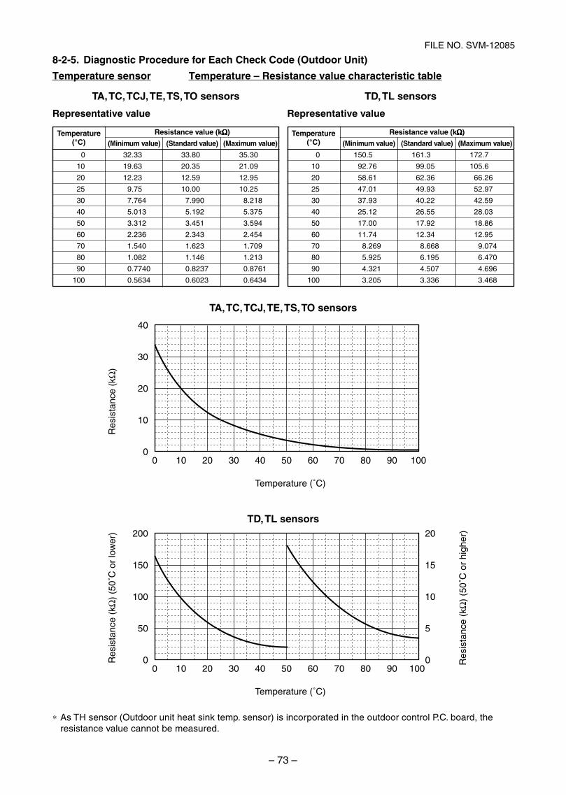
– 73 –
FILE NO. SVM-12085
Res
ista
nce
(kΩ
) (5
0˚C
or
low
er)
Res
ista
nce
(kΩ
) (5
0˚C
or
high
er)
00
50
100
150
200
0
5
10
15
20
10 20 30 40 50 60 70 80 90 100
Temperature (˚C)
Res
ista
nce
(kΩ
)
00
10
20
30
40
10 20 30 40 50 60 70 80 90 100
Temperature (˚C)
8-2-5. Diagnostic Procedure for Each Check Code (Outdoor Unit)
TD, TL sensors
Representative value
TA, TC, TCJ, TE, TS, TO sensors
TD, TL sensors
Temperature(°C)
0
10
20
25
30
40
50
60
70
80
90
100
Resistance value (kΩΩΩΩΩ)
(Minimum value) (Standard value) (Maximum value)
32.33 33.80 35.30
19.63 20.35 21.09
12.23 12.59 12.95
9.75 10.00 10.25
7.764 7.990 8.218
5.013 5.192 5.375
3.312 3.451 3.594
2.236 2.343 2.454
1.540 1.623 1.709
1.082 1.146 1.213
0.7740 0.8237 0.8761
0.5634 0.6023 0.6434
Temperature(°C)
0
10
20
25
30
40
50
60
70
80
90
100
Resistance value (kΩΩΩΩΩ)
(Minimum value) (Standard value) (Maximum value)
150.5 161.3 172.7
92.76 99.05 105.6
58.61 62.36 66.26
47.01 49.93 52.97
37.93 40.22 42.59
25.12 26.55 28.03
17.00 17.92 18.86
11.74 12.34 12.95
8.269 8.668 9.074
5.925 6.195 6.470
4.321 4.507 4.696
3.205 3.336 3.468
TA, TC, TCJ, TE, TS, TO sensors
Representative value
∗ As TH sensor (Outdoor unit heat sink temp. sensor) is incorporated in the outdoor control P.C. board, theresistance value cannot be measured.
Temperature sensor Temperature – Resistance value characteristic table
SVM-12085_051-114.indd 73SVM-12085_051-114.indd 73 12/06/12 11:15 AM12/06/12 11:15 AM
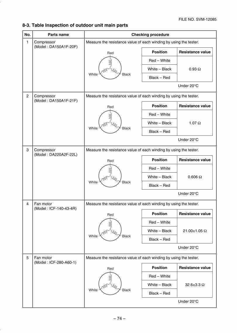
– 74 –
FILE NO. SVM-12085
8-3. Table Inspection of outdoor unit main parts
No. Parts name Checking procedure
1 Compressor(Model : DA150A1F-20F)
Measure the resistance value of each winding by using the tester.
Position Resistance value
Red – White
0.93 ΩWhite – Black
Black – Red
Under 20°C
Red
White Black
2 Compressor(Model : DA150A1F-21F)
Measure the resistance value of each winding by using the tester.
Position Resistance value
Red – White
1.07 ΩWhite – Black
Black – Red
Under 20°C
Red
White Black
3 Compressor(Model : DA220A2F-22L)
Measure the resistance value of each winding by using the tester.
Position Resistance value
Red – White
0.606 ΩWhite – Black
Black – Red
Under 20°C
Red
White Black
4 Fan motor(Model : ICF-140-43-4R)
Measure the resistance value of each winding by using the tester.
Position Resistance value
Red – White
21.00±1.05 ΩWhite – Black
Black – Red
Under 20°C
Red
White Black
5 Fan motor(Model : ICF-280-A60-1)
Measure the resistance value of each winding by using the tester.
Position Resistance value
Red – White
32.6±3.3 ΩWhite – Black
Black – Red
Under 20°C
Red
White Black
SVM-12085_051-114.indd 74SVM-12085_051-114.indd 74 12/06/12 11:15 AM12/06/12 11:15 AM
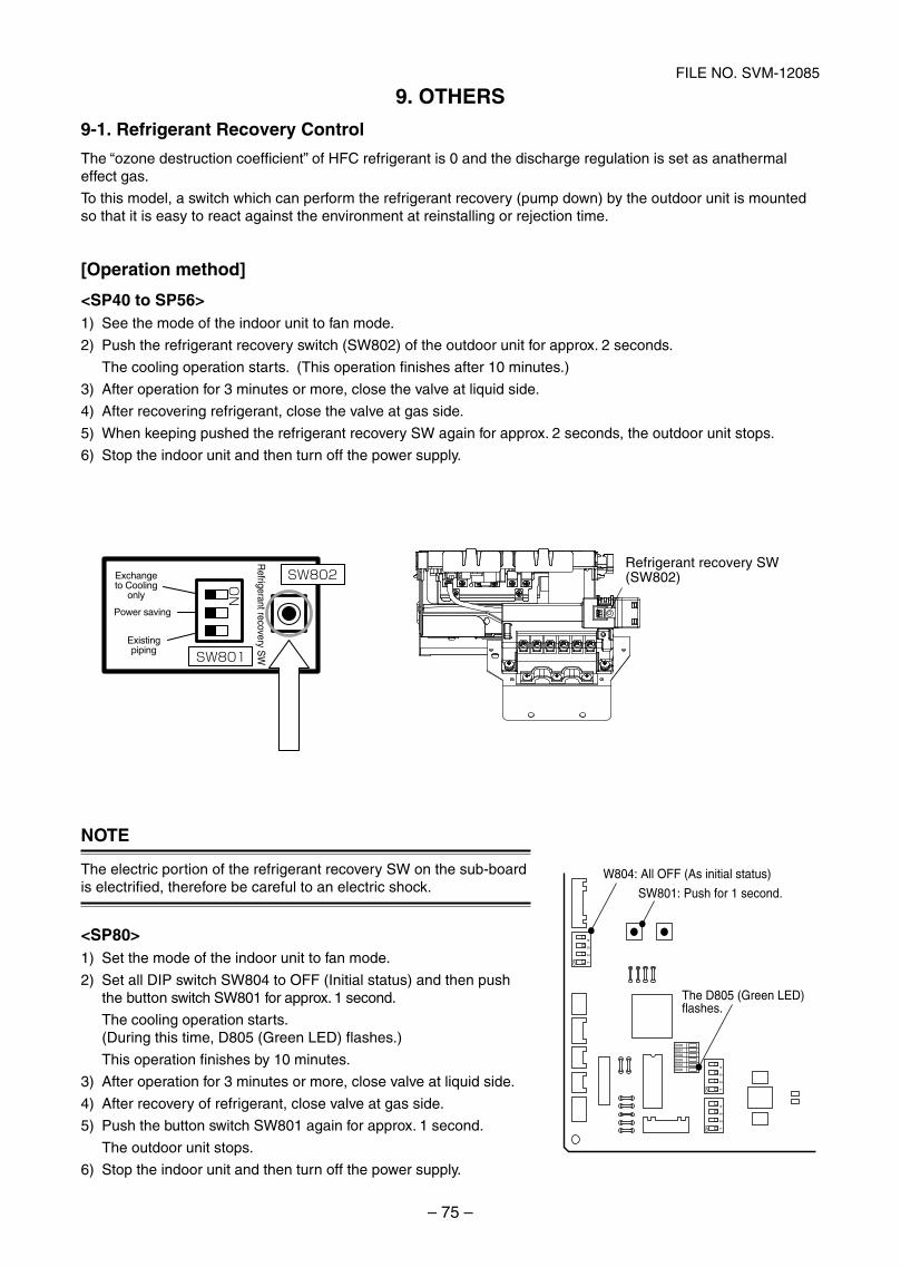
– 75 –
FILE NO. SVM-12085
The “ozone destruction coefficient” of HFC refrigerant is 0 and the discharge regulation is set as anathermaleffect gas.
To this model, a switch which can perform the refrigerant recovery (pump down) by the outdoor unit is mountedso that it is easy to react against the environment at reinstalling or rejection time.
[Operation method]
<SP40 to SP56>1) See the mode of the indoor unit to fan mode.
2) Push the refrigerant recovery switch (SW802) of the outdoor unit for approx. 2 seconds.
The cooling operation starts. (This operation finishes after 10 minutes.)
3) After operation for 3 minutes or more, close the valve at liquid side.
4) After recovering refrigerant, close the valve at gas side.
5) When keeping pushed the refrigerant recovery SW again for approx. 2 seconds, the outdoor unit stops.
6) Stop the indoor unit and then turn off the power supply.
NOTE
The electric portion of the refrigerant recovery SW on the sub-boardis electrified, therefore be careful to an electric shock.
<SP80>1) Set the mode of the indoor unit to fan mode.
2) Set all DIP switch SW804 to OFF (Initial status) and then pushthe button switch SW801 for approx. 1 second.
The cooling operation starts.(During this time, D805 (Green LED) flashes.)
This operation finishes by 10 minutes.
3) After operation for 3 minutes or more, close valve at liquid side.
4) After recovery of refrigerant, close valve at gas side.
5) Push the button switch SW801 again for approx. 1 second.
The outdoor unit stops.
6) Stop the indoor unit and then turn off the power supply.
Power saving
Exchangeto Cooling
only
Existingpiping
Refrigerant recovery S
W
Refrigerant recovery SW (SW802)SW802
SW801ON
12
34
ON
12
34
ON
12
34
ON
D800D801D802D803D804D805
SW801: Push for 1 second.
W804: All OFF (As initial status)
The D805 (Green LED) flashes.
9. OTHERS
9-1. Refrigerant Recovery Control
SVM-12085_051-114.indd 75SVM-12085_051-114.indd 75 12/06/12 11:15 AM12/06/12 11:15 AM
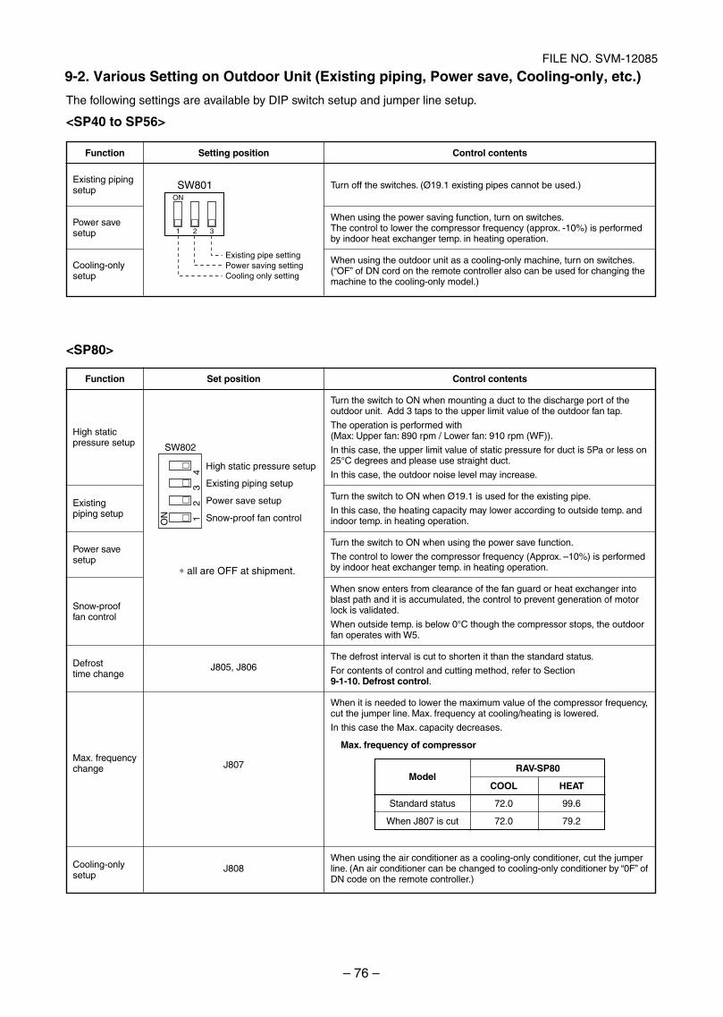
– 76 –
FILE NO. SVM-12085
12
34
ON
High static pressure setup
Existing piping setup
Power save setup
Snow-proof fan control
SW802
∗ all are OFF at shipment.
The following settings are available by DIP switch setup and jumper line setup.
<SP40 to SP56>
ON
SW801
1
Existing pipe settingPower saving settingCooling only setting
2 3
<SP80>
Function
Existing pipingsetup
Power savesetup
Cooling-onlysetup
Setting position Control contents
Turn off the switches. (Ø19.1 existing pipes cannot be used.)
When using the power saving function, turn on switches.The control to lower the compressor frequency (approx. -10%) is performedby indoor heat exchanger temp. in heating operation.
When using the outdoor unit as a cooling-only machine, turn on switches.(“OF” of DN cord on the remote controller also can be used for changing themachine to the cooling-only model.)
Function
High staticpressure setup
Existingpiping setup
Power savesetup
Snow-prooffan control
Defrosttime change
Max. frequencychange
Cooling-onlysetup
Set position
J805, J806
J807
J808
Control contents
Turn the switch to ON when mounting a duct to the discharge port of theoutdoor unit. Add 3 taps to the upper limit value of the outdoor fan tap.
The operation is performed with(Max: Upper fan: 890 rpm / Lower fan: 910 rpm (WF)).
In this case, the upper limit value of static pressure for duct is 5Pa or less on25°C degrees and please use straight duct.
In this case, the outdoor noise level may increase.
Turn the switch to ON when Ø19.1 is used for the existing pipe.
In this case, the heating capacity may lower according to outside temp. andindoor temp. in heating operation.
Turn the switch to ON when using the power save function.
The control to lower the compressor frequency (Approx. –10%) is performedby indoor heat exchanger temp. in heating operation.
When snow enters from clearance of the fan guard or heat exchanger intoblast path and it is accumulated, the control to prevent generation of motorlock is validated.
When outside temp. is below 0°C though the compressor stops, the outdoorfan operates with W5.
The defrost interval is cut to shorten it than the standard status.
For contents of control and cutting method, refer to Section9-1-10. Defrost control.
When it is needed to lower the maximum value of the compressor frequency,cut the jumper line. Max. frequency at cooling/heating is lowered.
In this case the Max. capacity decreases.
Max. frequency of compressor
When using the air conditioner as a cooling-only conditioner, cut the jumperline. (An air conditioner can be changed to cooling-only conditioner by “0F” ofDN code on the remote controller.)
Model
Standard status
When J807 is cut
RAV-SP80
COOL HEAT
72.0 99.6
72.0 79.2
9-2. Various Setting on Outdoor Unit (Existing piping, Power save, Cooling-only, etc.)
SVM-12085_051-114.indd 76SVM-12085_051-114.indd 76 12/06/12 11:15 AM12/06/12 11:15 AM
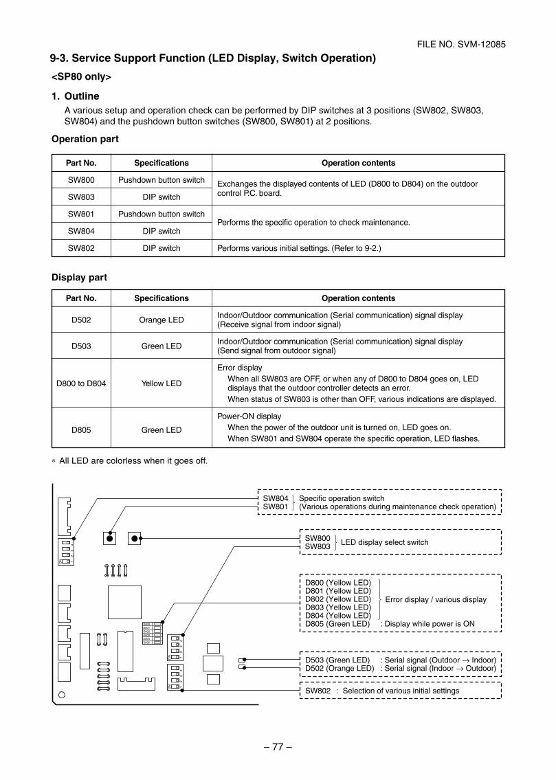
– 77 –
FILE NO. SVM-12085
<SP80 only>
1. OutlineA various setup and operation check can be performed by DIP switches at 3 positions (SW802, SW803,SW804) and the pushdown button switches (SW800, SW801) at 2 positions.
Operation part
Display part
∗ All LED are colorless when it goes off.
12
34
ON
12
34
ON
12
34
ON
D800D801D802D803D804D805
D503 (Green LED) : Serial signal (Outdoor → Indoor)D502 (Orange LED) : Serial signal (Indoor → Outdoor)
SW802 : Selection of various initial settings
LED display select switchSW800SW803
Error display / various display
D800 (Yellow LED)D801 (Yellow LED)D802 (Yellow LED)D803 (Yellow LED)D804 (Yellow LED)D805 (Green LED) : Display while power is ON
Specific operation switch(Various operations during maintenance check operation)
SW804SW801
Part No.
D502
D503
D800 to D804
D805
Specifications
Orange LED
Green LED
Yellow LED
Green LED
Operation contents
Indoor/Outdoor communication (Serial communication) signal display(Receive signal from indoor signal)
Indoor/Outdoor communication (Serial communication) signal display(Send signal from outdoor signal)
Error displayWhen all SW803 are OFF, or when any of D800 to D804 goes on, LEDdisplays that the outdoor controller detects an error.When status of SW803 is other than OFF, various indications are displayed.
Power-ON displayWhen the power of the outdoor unit is turned on, LED goes on.When SW801 and SW804 operate the specific operation, LED flashes.
Part No.
SW800
SW803
SW801
SW804
SW802
Specifications
Pushdown button switch
DIP switch
Pushdown button switch
DIP switch
DIP switch
Operation contents
Exchanges the displayed contents of LED (D800 to D804) on the outdoorcontrol P.C. board.
Performs the specific operation to check maintenance.
Performs various initial settings. (Refer to 9-2.)
9-3. Service Support Function (LED Display, Switch Operation)
SVM-12085_051-114.indd 77SVM-12085_051-114.indd 77 12/06/12 11:15 AM12/06/12 11:15 AM
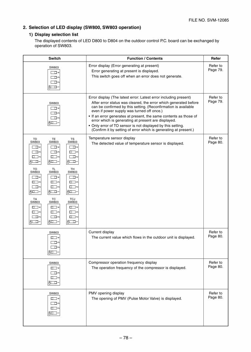
– 78 –
FILE NO. SVM-12085
TCSW803
TLSW803
TESW803
TASW803
TOSW803
TDSW803
TCJSW803
THSW803
TSSW803
SW803
ON
23
41
SW803
ON
23
41
ON
23
41
ON
23
41
ON
23
41
ON
23
41
ON
23
41
ON
23
41
ON
23
41
ON
23
41
ON
23
41
SW803
ON
23
41
SW803
ON
23
41
SW803
ON
23
41
2. Selection of LED display (SW800, SW803 operation)
1) Display selection listThe displayed contents of LED D800 to D804 on the outdoor control P.C. board can be exchanged byoperation of SW803.
Switch Function / Contents
Error display (Error generating at present)Error generating at present is displayed.This switch goes off when an error does not generate.
Error display (The latest error: Latest error including present)After error status was cleared, the error which generated beforecan be confirmed by this setting. (Reconfirmation is availableeven if power supply was turned off once.)If an error generates at present, the same contents as those oferror which is generating at present are displayed.Only error of TO sensor is not displayed by this setting.(Confirm it by setting of error which is generating at present.)
Temperature sensor displayThe detected value of temperature sensor is displayed.
Current displayThe current value which flows in the outdoor unit is displayed.
Compressor operation frequency displayThe operation frequency of the compressor is displayed.
PMV opening displayThe opening of PMV (Pulse Motor Valve) is displayed.
Refer
Refer toPage 79.
Refer toPage 79.
Refer toPage 80.
Refer toPage 80.
Refer toPage 80.
Refer toPage 80.
SVM-12085_051-114.indd 78SVM-12085_051-114.indd 78 12/06/12 11:15 AM12/06/12 11:15 AM
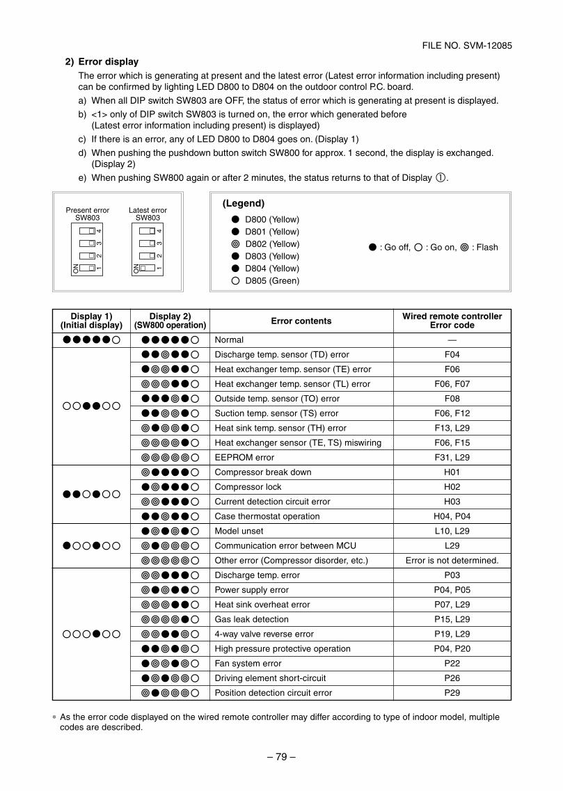
– 79 –
FILE NO. SVM-12085
2) Error displayThe error which is generating at present and the latest error (Latest error information including present)can be confirmed by lighting LED D800 to D804 on the outdoor control P.C. board.
a) When all DIP switch SW803 are OFF, the status of error which is generating at present is displayed.
b) <1> only of DIP switch SW803 is turned on, the error which generated before(Latest error information including present) is displayed)
c) If there is an error, any of LED D800 to D804 goes on. (Display 1)
d) When pushing the pushdown button switch SW800 for approx. 1 second, the display is exchanged.(Display 2)
e) When pushing SW800 again or after 2 minutes, the status returns to that of Display .
(Legend)
D800 (Yellow) D801 (Yellow) D802 (Yellow) D803 (Yellow) D804 (Yellow) D805 (Green)
: Go off, : Go on, : Flash
Present errorSW803
ON
23
41
Latest errorSW803
ON
23
41
∗ As the error code displayed on the wired remote controller may differ according to type of indoor model, multiplecodes are described.
Display 1)(Initial display)
Display 2)(SW800 operation) Error contents
Normal
Discharge temp. sensor (TD) error
Heat exchanger temp. sensor (TE) error
Heat exchanger temp. sensor (TL) error
Outside temp. sensor (TO) error
Suction temp. sensor (TS) error
Heat sink temp. sensor (TH) error
Heat exchanger sensor (TE, TS) miswiring
EEPROM error
Compressor break down
Compressor lock
Current detection circuit error
Case thermostat operation
Model unset
Communication error between MCU
Other error (Compressor disorder, etc.)
Discharge temp. error
Power supply error
Heat sink overheat error
Gas leak detection
4-way valve reverse error
High pressure protective operation
Fan system error
Driving element short-circuit
Position detection circuit error
Wired remote controllerError code
—
F04
F06
F06, F07
F08
F06, F12
F13, L29
F06, F15
F31, L29
H01
H02
H03
H04, P04
L10, L29
L29
Error is not determined.
P03
P04, P05
P07, L29
P15, L29
P19, L29
P04, P20
P22
P26
P29
SVM-12085_051-114.indd 79SVM-12085_051-114.indd 79 12/06/12 11:15 AM12/06/12 11:15 AM
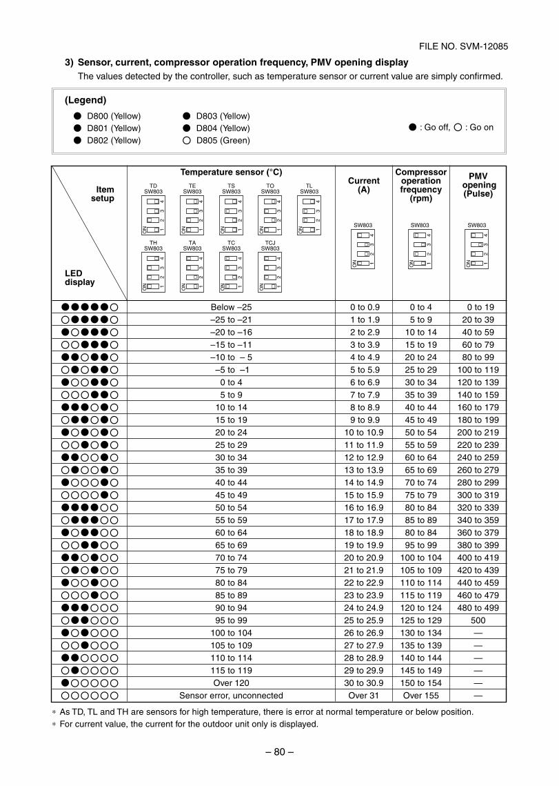
– 80 –
FILE NO. SVM-12085
THSW803
ON
23
41
SW803 SW803 SW803
ON
23
41 ON
23
41 ON
23
41
TDSW803
ON
23
41
TASW803
ON
23
41
TESW803
ON
23
41
TCSW803
ON
23
41
TSSW803
ON
23
41
TCJSW803
ON
23
41
TOSW803
ON
23
41
TLSW803
ON
23
41
3) Sensor, current, compressor operation frequency, PMV opening displayThe values detected by the controller, such as temperature sensor or current value are simply confirmed.
(Legend)
D800 (Yellow) D803 (Yellow) D801 (Yellow) D804 (Yellow) D802 (Yellow) D805 (Green)
: Go off, : Go on
∗ As TD, TL and TH are sensors for high temperature, there is error at normal temperature or below position.∗ For current value, the current for the outdoor unit only is displayed.
Itemsetup
LEDdisplay
Temperature sensor (°C)
Below –25–25 to –21–20 to –16–15 to –11–10 to – 5
–5 to –10 to 45 to 9
10 to 1415 to 1920 to 2425 to 2930 to 3435 to 3940 to 4445 to 4950 to 5455 to 5960 to 6465 to 6970 to 7475 to 7980 to 8485 to 8990 to 9495 to 99
100 to 104105 to 109110 to 114115 to 119Over 120
Sensor error, unconnected
Current(A)
0 to 0.9 1 to 1.9 2 to 2.9 3 to 3.9 4 to 4.9 5 to 5.9 6 to 6.9 7 to 7.9 8 to 8.9 9 to 9.9
10 to 10.911 to 11.912 to 12.913 to 13.914 to 14.915 to 15.916 to 16.917 to 17.918 to 18.919 to 19.920 to 20.921 to 21.922 to 22.923 to 23.924 to 24.925 to 25.926 to 26.927 to 27.928 to 28.929 to 29.930 to 30.9Over 31
Compressoroperationfrequency
(rpm)
0 to 45 to 9
10 to 1415 to 1920 to 2425 to 2930 to 3435 to 3940 to 4445 to 4950 to 5455 to 5960 to 6465 to 6970 to 7475 to 7980 to 8485 to 8980 to 8495 to 99
100 to 104105 to 109110 to 114115 to 119120 to 124125 to 129130 to 134135 to 139140 to 144145 to 149150 to 154Over 155
PMV opening(Pulse)
0 to 1920 to 3940 to 5960 to 7980 to 99
100 to 119120 to 139140 to 159160 to 179180 to 199200 to 219220 to 239240 to 259260 to 279280 to 299300 to 319320 to 339340 to 359360 to 379380 to 399400 to 419420 to 439440 to 459460 to 479480 to 499
500——————
SVM-12085_051-114.indd 80SVM-12085_051-114.indd 80 12/06/12 11:15 AM12/06/12 11:15 AM
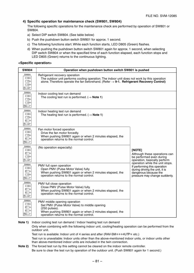
– 81 –
FILE NO. SVM-12085
4) Specific operation for maintenance check (SW801, SW804)The following specific operations for the maintenance check are performed by operation of SW801 orSW804.
a) Select DIP switch SW804. (See table below)
b) Push the pushdown button switch SW801 for approx. 1 second.
c) The following functions start. While each function starts, LED D805 (Green) flashes.
d) When pushing the pushdown button switch SW801 again for approx. 1 second, when selectingDIP switch SW804 or when the specified time of each function elapsed, each function stops andLED D805 (Green) returns to the continuous lighting.
<Specific operation>
Note 1) Indoor cooling test run demand / Indoor heating test run demandOnly when combining with the following indoor unit, cooling/heating operation can be performed from theoutdoor unit.Test run is available: Indoor unit of 4 series and after (RAV-SM∗∗∗4UTP∗ etc.)Test run is unavailable: Indoor units other than the above-mentioned indoor units, or indoor units otherthan above-mentioned indoor units are included in the twin connection.
Note 2) The forced test run by this setting cannot be cleared on the indoor remote controller.Be sure to clear the test run by operation of the outdoor unit. (Push SW801 again for 1 second.)
SW804
ON
23
41
SW804
ON
23
41
SW804
ON
23
41
SW804
ON
23
41
SW804
ON
23
41
SW804
ON
23
41
SW804
ON
23
41
SW804
ON
23
41
SW804 Operation when pushdown button switch SW801 is pushed
Refrigerant recovery operationThe outdoor unit performs cooling operation. The indoor unit does not work by this operationalone. Therefore operate the fan beforehand. (Refer → 9-1. Refrigerant Recovery Control)
Indoor cooling test run demandThe cooling test run is performed. (→ Note 1)
Indoor heating test run demandThe heating test run is performed. (→ Note 1)
Fan motor forced operationDrive the fan motor forcedly.When pushing SW801 again or when 2 minutes elapsed, theoperation returns to the normal control.
(No operation especially)
PMV full open operationOpen PMV (Pulse Motor Valve) fully.When pushing SW801 again or when 2 minutes elapsed, theoperation returns to the normal control.
PMV full close operationClose PMV (Pulse Motor Valve) fully.When pushing SW801 again or when 2 minutes elapsed, theoperation returns to the normal control.
PMV middle opening operationSet PMV (Pulse Motor Valve) to middle opening(250 pulses).When pushing SW801 again or when 2 minutes elapsed, theoperation returns to the normal control.
[NOTE]Although these operations canbe performed even duringoperation, basically performoperation while the unit stops.If performing this operationduring driving the unit, it isdangerous because thepressure may change suddenly.
SVM-12085_051-114.indd 81SVM-12085_051-114.indd 81 12/06/12 11:15 AM12/06/12 11:15 AM
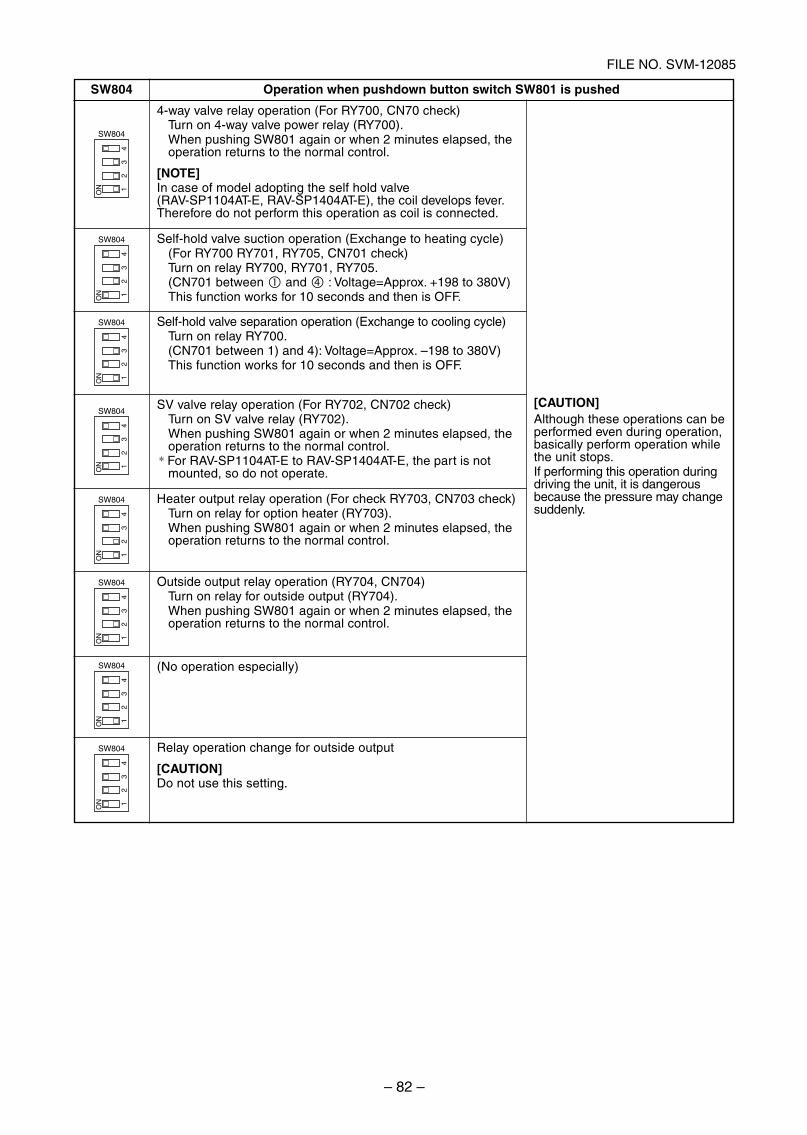
– 82 –
FILE NO. SVM-12085
SW804
ON
23
41
SW804
ON
23
41
SW804
ON
23
41
SW804
ON
23
41
SW804
ON
23
41
SW804
ON
23
41
SW804
ON
23
41
SW804
ON
23
41
SW804 Operation when pushdown button switch SW801 is pushed
4-way valve relay operation (For RY700, CN70 check)Turn on 4-way valve power relay (RY700).When pushing SW801 again or when 2 minutes elapsed, theoperation returns to the normal control.
[NOTE]In case of model adopting the self hold valve(RAV-SP1104AT-E, RAV-SP1404AT-E), the coil develops fever.Therefore do not perform this operation as coil is connected.
Self-hold valve suction operation (Exchange to heating cycle)(For RY700 RY701, RY705, CN701 check)Turn on relay RY700, RY701, RY705.(CN701 between and : Voltage=Approx. +198 to 380V)This function works for 10 seconds and then is OFF.
Self-hold valve separation operation (Exchange to cooling cycle)Turn on relay RY700.(CN701 between 1) and 4): Voltage=Approx. –198 to 380V)This function works for 10 seconds and then is OFF.
SV valve relay operation (For RY702, CN702 check)Turn on SV valve relay (RY702).When pushing SW801 again or when 2 minutes elapsed, theoperation returns to the normal control.
∗ For RAV-SP1104AT-E to RAV-SP1404AT-E, the part is notmounted, so do not operate.
Heater output relay operation (For check RY703, CN703 check)Turn on relay for option heater (RY703).When pushing SW801 again or when 2 minutes elapsed, theoperation returns to the normal control.
Outside output relay operation (RY704, CN704)Turn on relay for outside output (RY704).When pushing SW801 again or when 2 minutes elapsed, theoperation returns to the normal control.
(No operation especially)
Relay operation change for outside output
[CAUTION]Do not use this setting.
[CAUTION]Although these operations can beperformed even during operation,basically perform operation whilethe unit stops.If performing this operation duringdriving the unit, it is dangerousbecause the pressure may changesuddenly.
SVM-12085_051-114.indd 82SVM-12085_051-114.indd 82 12/06/12 11:15 AM12/06/12 11:15 AM
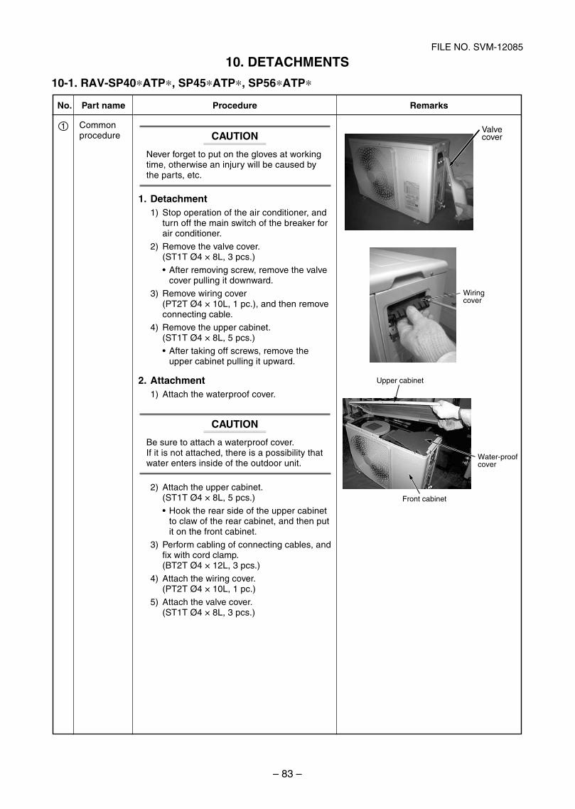
– 83 –
FILE NO. SVM-12085
No.
1
Part name
Commonprocedure
Procedure
CAUTION
Never forget to put on the gloves at workingtime, otherwise an injury will be caused bythe parts, etc.
1. Detachment1) Stop operation of the air conditioner, and
turn off the main switch of the breaker forair conditioner.
2) Remove the valve cover.(ST1T Ø4 × 8L, 3 pcs.)
After removing screw, remove the valvecover pulling it downward.
3) Remove wiring cover(PT2T Ø4 × 10L, 1 pc.), and then removeconnecting cable.
4) Remove the upper cabinet.(ST1T Ø4 × 8L, 5 pcs.)
After taking off screws, remove theupper cabinet pulling it upward.
2. Attachment1) Attach the waterproof cover.
CAUTION
Be sure to attach a waterproof cover.If it is not attached, there is a possibility thatwater enters inside of the outdoor unit.
2) Attach the upper cabinet.(ST1T Ø4 × 8L, 5 pcs.)
Hook the rear side of the upper cabinetto claw of the rear cabinet, and then putit on the front cabinet.
3) Perform cabling of connecting cables, andfix with cord clamp.(BT2T Ø4 × 12L, 3 pcs.)
4) Attach the wiring cover.(PT2T Ø4 × 10L, 1 pc.)
5) Attach the valve cover.(ST1T Ø4 × 8L, 3 pcs.)
Remarks
Valve cover
Wiringcover
Upper cabinet
Water-proofcover
Front cabinet
10. DETACHMENTS
10-1. RAV-SP40*ATP*, SP45*ATP*, SP56*ATP*
SVM-12085_051-114.indd 83SVM-12085_051-114.indd 83 12/06/12 11:15 AM12/06/12 11:15 AM
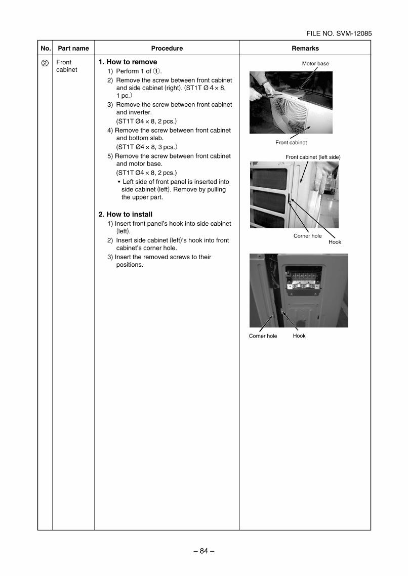
– 84 –
FILE NO. SVM-12085
No.
2
Part name
Front cabinet
Procedure Remarks
1. How to remove1) Perform 1 of 1.2) Remove the screw between front cabinet
and side cabinet (right). (ST1T Ø4× 8,1 pc.)
3) Remove the screw between front cabinet and inverter.
(ST1T Ø4 × 8, 2 pcs.)4) Remove the screw between front cabinet
and bottom slab. (ST1T Ø4 × 8, 3 pcs.)5) Remove the screw between front cabinet
and motor base. (ST1T Ø4 × 8, 2 pcs.)
side cabinet (left). Remove by pulling the upper part.
2. How to install1) Insert front panel’s hook into side cabinet (left).
2) Insert side cabinet (left)’s hook into front cabinet’s corner hole.
3) Insert the removed screws to their positions.
Hook
Motor base
Front cabinet (left side)
Front cabinet
Corner hole
HookCorner hole
SVM-12085_051-114.indd 84SVM-12085_051-114.indd 84 12/07/12 11:00 AM12/07/12 11:00 AM
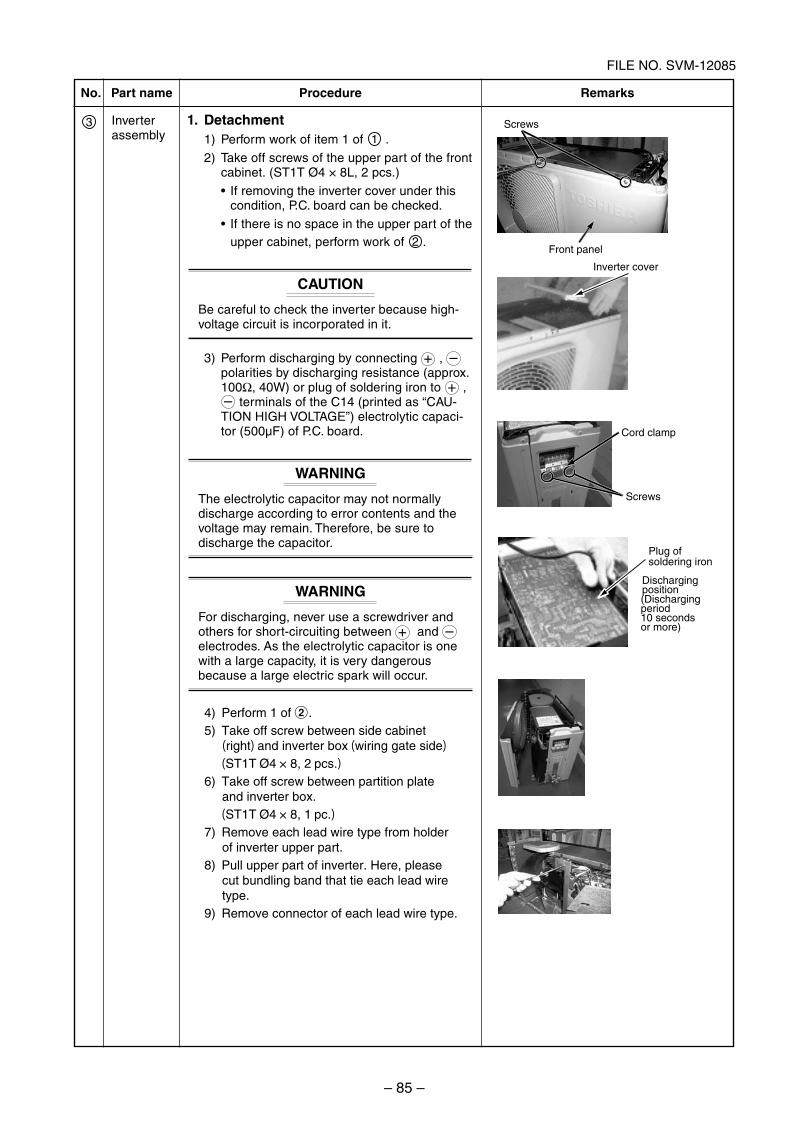
– 85 –
FILE NO. SVM-12085
Inverter cover
(Dischargingperiod10 seconds or more)
Plug of soldering iron
Dischargingposition
No.
3
Part name
Inverterassembly
Procedure
1. Detachment1) Perform work of item 1 of 1 .
2) Take off screws of the upper part of the frontcabinet. (ST1T Ø4 × 8L, 2 pcs.)
If removing the inverter cover under thiscondition, P.C. board can be checked.
If there is no space in the upper part of theupper cabinet, perform work of 2 .
CAUTION
Be careful to check the inverter because high-voltage circuit is incorporated in it.
3) Perform discharging by connecting + , –polarities by discharging resistance (approx.100Ω, 40W) or plug of soldering iron to + ,– terminals of the C14 (printed as “CAU-TION HIGH VOLTAGE”) electrolytic capaci-tor (500μF) of P.C. board.
WARNING
The electrolytic capacitor may not normallydischarge according to error contents and thevoltage may remain. Therefore, be sure todischarge the capacitor.
WARNING
For discharging, never use a screwdriver andothers for short-circuiting between + and –electrodes. As the electrolytic capacitor is onewith a large capacity, it is very dangerousbecause a large electric spark will occur.
Remarks
Screws
Cord clamp
Screws
4) Perform 1 of 2.5) Take off screw between side cabinet (right) and inverter box (wiring gate side)
(ST1T Ø4 × 8, 2 pcs.)6) Take off screw between partition plate
and inverter box. (ST1T Ø4 × 8, 1 pc.)7) Remove each lead wire type from holder
of inverter upper part.8) Pull upper part of inverter. Here, please
cut bundling band that tie each lead wire type.
9) Remove connector of each lead wire type.
Front panel
SVM-12085_051-114.indd 85SVM-12085_051-114.indd 85 12/07/12 11:14 AM12/07/12 11:14 AM
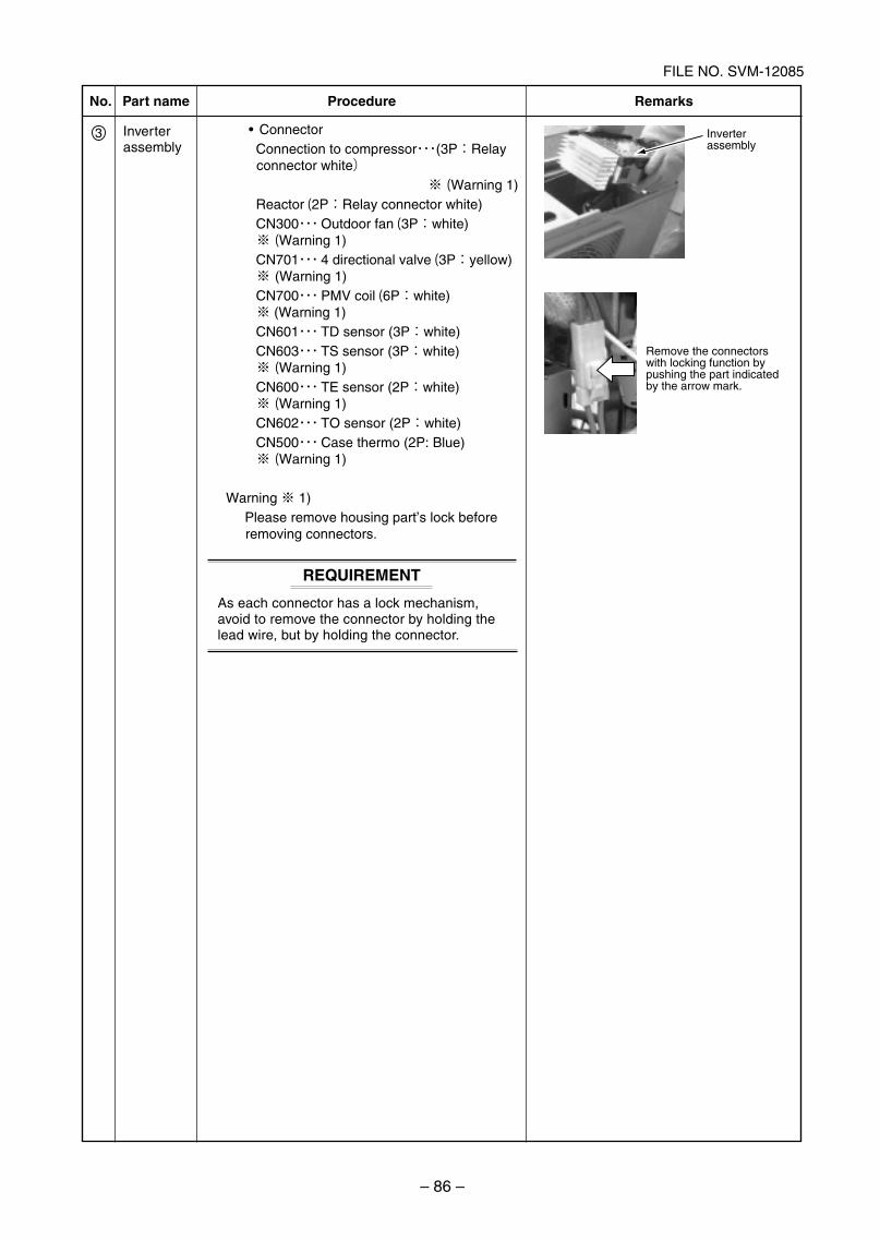
– 86 –
FILE NO. SVM-12085
Inverterassembly
Remove the connectors with locking function by pushing the part indicated by the arrow mark.
No.
3
Part name
Inverterassembly
Procedure Remarks
REQUIREMENT
As each connector has a lock mechanism,avoid to remove the connector by holding thelead wire, but by holding the connector.
・・・(3P:Relay connector white)
※ (Warning 1) Reactor (2P:Relay connector white)
・・・ Outdoor fan (3P:white) ※ (Warning 1)
・・・ 4 directional valve (3P:yellow) ※ (Warning 1)
・・・ PMV coil (6P:white) ※ (Warning 1)
・・・ TD sensor (3P:white)・・・ TS sensor (3P:white)
※ (Warning 1)・・・ TE sensor (2P:white)
※ (Warning 1)・・・ TO sensor (2P:white)・・・ )
※ (Warning 1)
Warning ※ 1) Please remove housing part’s lock before
removing connectors.
SVM-12085_051-114.indd 86SVM-12085_051-114.indd 86 12/07/12 11:00 AM12/07/12 11:00 AM
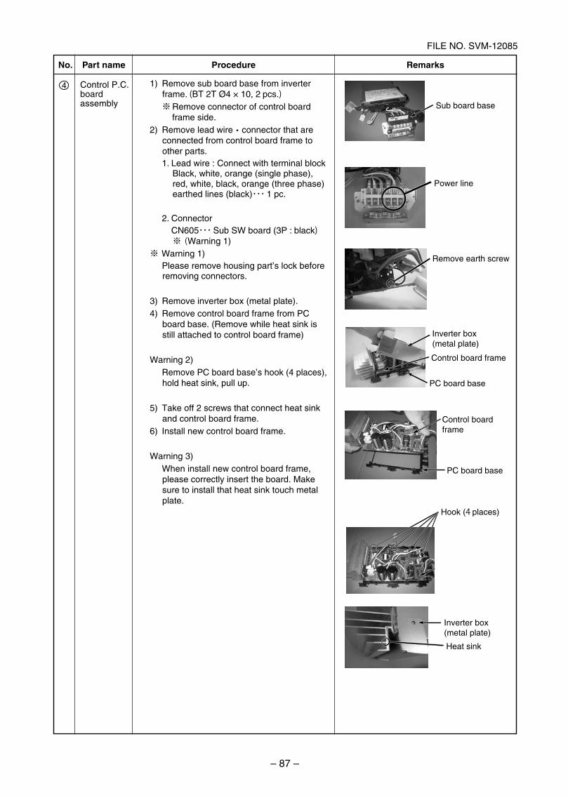
– 87 –
FILE NO. SVM-12085
No.
4
Part name Procedure Remarks
Control P.C. board assembly
1) Remove sub board base from inverter frame. (BT 2T Ø4 × 10, 2 pcs.)
※ Remove connector of control board frame side.
2) Remove lead wire・connector that are connected from control board frame to other parts.1. Lead wire : Connect with terminal block
Black, white, orange (single phase), red, white, black, orange (three phase) earthed lines (black)・・・ 1 pc.
2. Connector CN605・・・ Sub SW board (3P : black)※ (Warning 1)
※ Warning 1) Please remove housing part’s lock before
removing connectors.
3) Remove inverter box (metal plate).4) Remove control board frame from PC
board base. (Remove while heat sink is still attached to control board frame)
Warning 2) Remove PC board base’s hook (4 places),
hold heat sink, pull up.
5) Take off 2 screws that connect heat sink and control board frame.
6) Install new control board frame.
Warning 3) When install new control board frame,
please correctly insert the board. Make sure to install that heat sink touch metal plate.
Sub board base
Power line
Remove earth screw
Inverter box (metal plate)
Inverter box (metal plate)
Control board frame
PC board base
Control board frame
PC board base
Hook (4 places)
Heat sink
SVM-12085_051-114.indd 87SVM-12085_051-114.indd 87 12/07/12 11:00 AM12/07/12 11:00 AM
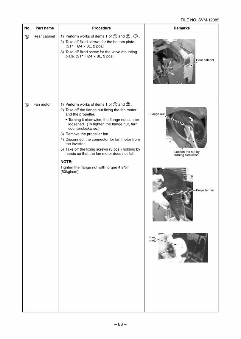
– 88 –
FILE NO. SVM-12085
Rear cabinet
Flange nut
Loosen the nut by turning clockwise
Propeller fan
Fanmotor
No.
5
6
Part name
Rear cabinet
Fan motor
Procedure
1) Perform works of items 1 of 1 and 2 , 3 .
2) Take off fixed screws for the bottom plate.(ST1T Ø4 × 8L, 2 pcs.)
1) Perform works of items 1 of 1 and 2 .
2) Take off the flange nut fixing the fan motorand the propeller.
Turning it clockwise, the flange nut can beloosened. (To tighten the flange nut, turncounterclockwise.)
3) Remove the propeller fan.
4) Disconnect the connector for fan motor fromthe inverter.
5) Take off the fixing screws (3 pcs.) holding byhands so that the fan motor does not fall.
NOTE:Tighten the flange nut with torque 4.9Nm(50kgf/cm).
Remarks
3) Take off fixed screw for the valve mountingplate. (ST1T Ø4 × 8L, 3 pcs.)
SVM-12085_051-114.indd 88SVM-12085_051-114.indd 88 12/06/12 11:15 AM12/06/12 11:15 AM
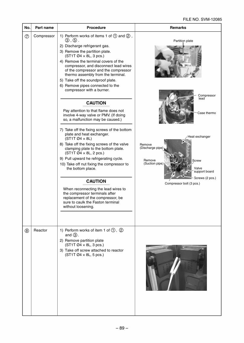
– 89 –
FILE NO. SVM-12085
Partition plate
Compressor
Case thermo
lead
Heat exchanger
Screw
Valvesupport board
Screws (2 pcs.)
Compressor bolt (3 pcs.)
Remove(Suction pipe)
Remove(Discharge pipe)
No.
7
8
Part name
Compressor
Reactor
Procedure
1) Perform works of items 1 of 1 and 2 ,3 , 5 .
2) Discharge refrigerant gas.
3) Remove the partition plate.(ST1T Ø4 × 8L, 3 pcs.)
6) Remove pipes connected to thecompressor with a burner.
CAUTION
Pay attention to that flame does notinvolve 4-way valve or PMV. (If doingso, a malfunction may be caused.)
7) Take off the fixing screws of the bottomplate and heat exchanger.(ST1T Ø4 × 8L)
8) Take off the fixing screws of the valveclamping plate to the bottom plate.(ST1T Ø4 × 8L, 2 pcs.)
9) Pull upward he refrigerating cycle.
10) Take off nut fixing the compressor tothe bottom place.
CAUTION
When reconnecting the lead wires tothe compressor terminals afterreplacement of the compressor, besure to caulk the Faston terminalwithout loosening.
1) Perform works of item 1 of 1 2 ,3 .and
Remarks
4) Remove the terminal covers of thecompressor, and disconnect lead wiresof the compressor and the compressorthermo assembly from the terminal.
5) Take off the soundproof plate.
2) Remove partition plate(ST1T Ø4 × 8L, 3 pcs.)
3) Take off screw attached to reactor(ST1T Ø4 × 8L, 5 pcs.)
SVM-12085_051-114.indd 89SVM-12085_051-114.indd 89 12/06/12 11:15 AM12/06/12 11:15 AM
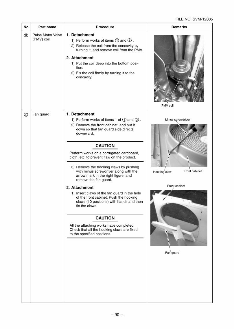
– 90 –
FILE NO. SVM-12085
Minus screwdriver
Front cabinetHooking claw
Front cabinet
Fan guard
No.
9
10
Part name
Pulse Motor Valve(PMV) coil
Fan guard
Procedure
1. Detachment1) Perform works of items 1 and 2 .
2) Release the coil from the concavity byturning it, and remove coil from the PMV.
2. Attachment1) Put the coil deep into the bottom posi-
tion.
2) Fix the coil firmly by turning it to theconcavity.
1. Detachment1) Perform works of items 1 of 1 and 2 .
2) Remove the front cabinet, and put itdown so that fan guard side directsdownward.
CAUTION
Perform works on a corrugated cardboard,cloth, etc. to prevent flaw on the product.
3) Remove the hooking claws by pushingwith minus screwdriver along with thearrow mark in the right figure, andremove the fan guard.
2. Attachment1) Insert claws of the fan guard in the hole
of the front cabinet. Push the hookingclaws (10 positions) with hands and thenfix the claws.
CAUTION
All the attaching works have completed.Check that all the hooking claws are fixedto the specified positions.
Remarks
PMV coil
SVM-12085_051-114.indd 90SVM-12085_051-114.indd 90 12/06/12 11:15 AM12/06/12 11:15 AM
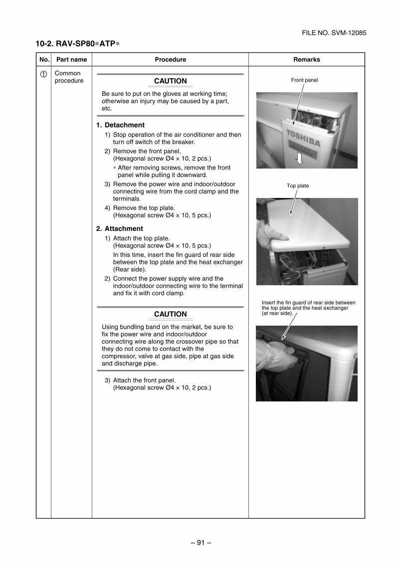
– 91 –
FILE NO. SVM-12085
No.
1
Part name
Commonprocedure
Procedure
CAUTION
Be sure to put on the gloves at working time;otherwise an injury may be caused by a part,etc.
1. Detachment1) Stop operation of the air conditioner and then
turn off switch of the breaker.
2) Remove the front panel.(Hexagonal screw Ø4 × 10, 2 pcs.)
∗ After removing screws, remove the frontpanel while pulling it downward.
3) Remove the power wire and indoor/outdoorconnecting wire from the cord clamp and theterminals.
4) Remove the top plate.(Hexagonal screw Ø4 × 10, 5 pcs.)
2. Attachment1) Attach the top plate.
(Hexagonal screw Ø4 × 10, 5 pcs.)
In this time, insert the fin guard of rear sidebetween the top plate and the heat exchanger(Rear side).
2) Connect the power supply wire and theindoor/outdoor connecting wire to the terminaland fix it with cord clamp.
CAUTION
Using bundling band on the market, be sure tofix the power wire and indoor/outdoorconnecting wire along the crossover pipe so thatthey do not come to contact with thecompressor, valve at gas side, pipe at gas sideand discharge pipe.
3) Attach the front panel.(Hexagonal screw Ø4 × 10, 2 pcs.)
Remarks
Front panel
Top plate
Insert the fin guard of rear side between the top plate and the heat exchanger (at rear side).
10-2. RAV-SP80*ATP*
SVM-12085_051-114.indd 91SVM-12085_051-114.indd 91 12/06/12 11:15 AM12/06/12 11:15 AM
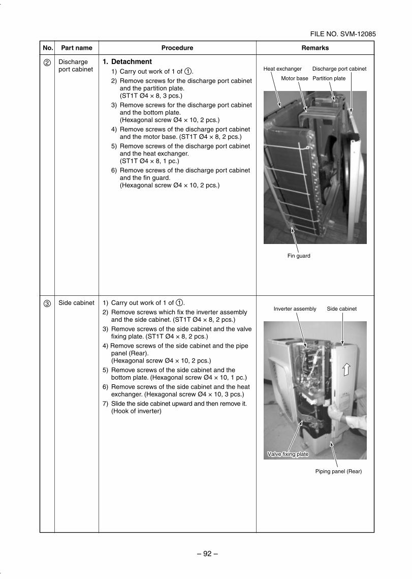
– 92 –
FILE NO. SVM-12085
Heat exchanger
Fin guard
Motor base
Discharge port cabinet
Partition plate
Inverter assembly
Piping panel (Rear)
Side cabinet
Valve fixing plateValve fixing plate
No.
2
Part name
Dischargeport cabinet
Procedure
1. Detachment1) Carry out work of 1 of 1 .
2) Remove screws for the discharge port cabinetand the partition plate.(ST1T Ø4 × 8, 3 pcs.)
3) Remove screws for the discharge port cabinetand the bottom plate.(Hexagonal screw Ø4 × 10, 2 pcs.)
4) Remove screws of the discharge port cabinetand the motor base. (ST1T Ø4 × 8, 2 pcs.)
5) Remove screws of the discharge port cabinetand the heat exchanger.(ST1T Ø4 × 8, 1 pc.)
6) Remove screws of the discharge port cabinetand the fin guard.(Hexagonal screw Ø4 × 10, 2 pcs.)
Remarks
1) Carry out work of 1 of 1 .
2) Remove screws which fix the inverter assemblyand the side cabinet. (ST1T Ø4 × 8, 2 pcs.)
3) Remove screws of the side cabinet and the valvefixing plate. (ST1T Ø4 × 8, 2 pcs.)
4) Remove screws of the side cabinet and the pipepanel (Rear).(Hexagonal screw Ø4 × 10, 2 pcs.)
5) Remove screws of the side cabinet and thebottom plate. (Hexagonal screw Ø4 × 10, 1 pc.)
6) Remove screws of the side cabinet and the heatexchanger. (Hexagonal screw Ø4 × 10, 3 pcs.)
7) Slide the side cabinet upward and then remove it.(Hook of inverter)
Side cabinet3
SVM-12085_051-114.indd 92SVM-12085_051-114.indd 92 12/06/12 11:15 AM12/06/12 11:15 AM
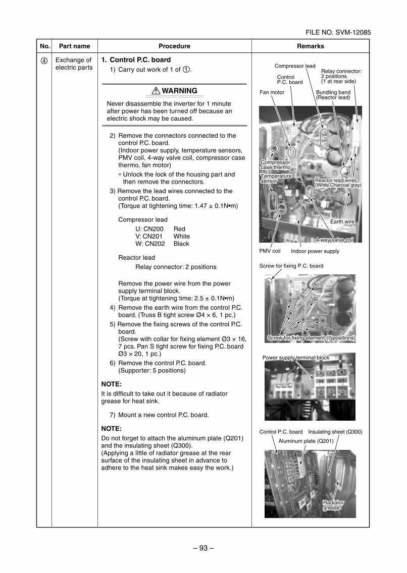
– 93 –
FILE NO. SVM-12085
No.
4
Part name
Exchange ofelectric parts
Procedure
1. Control P.C. board1) Carry out work of 1 of 1 .
WARNING
Never disassemble the inverter for 1 minuteafter power has been turned off because anelectric shock may be caused.
2) Remove the connectors connected to thecontrol P.C. board.(Indoor power supply, temperature sensors,PMV coil, 4-way valve coil, compressor casethermo, fan motor)
∗ Unlock the lock of the housing part andthen remove the connectors.
3) Remove the lead wires connected to thecontrol P.C. board.(Torque at tightening time: 1.47 ± 0.1N m)
Compressor lead
U: CN200 RedV: CN201 WhiteW: CN202 Black
Reactor lead
Relay connector: 2 positions
Remove the power wire from the powersupply terminal block.(Torque at tightening time: 2.5 ± 0.1N m)
4) Remove the earth wire from the control P.C.board. (Truss B tight screw Ø4 × 6, 1 pc.)
5) Remove the fixing screws of the control P.C.board.(Screw with collar for fixing element Ø3 × 16,7 pcs. Pan S tight screw for fixing P.C. boardØ3 × 20, 1 pc.)
6) Remove the control P.C. board.(Supporter: 5 positions)
NOTE:It is difficult to take out it because of radiatorgrease for heat sink.
7) Mount a new control P.C. board.
NOTE:Do not forget to attach the aluminum plate (Q201)and the insulating sheet (Q300).(Applying a little of radiator grease at the rearsurface of the insulating sheet in advance toadhere to the heat sink makes easy the work.)
Remarks
Screw for fixing P.C. board
Control P.C. board Insulating sheet (Q300)
Aluminum plate (Q201)
Power supply terminal block
Radiatorgrease
Screw for fixing element (7 positions)
PMV coil Indoor power supply
4-way valve coil4-way valve coil
Earth wire
ControlP.C. board
Fan motor Bundling band (Reactor lead)
Compressor lead
Reactor lead wires (White,Charcoal gray)
Temperaturesensor
Compressorcase thermo
Power supply terminal block
Radiatorgrease
Screw for fixing element (7 positions)
Earth wire
Reactor lead wires (White,Charcoal gray)
Temperaturesensor
Compressorcase thermo
Relay connector: 2 positions (1 at rear side)
SVM-12085_051-114.indd 93SVM-12085_051-114.indd 93 12/06/12 11:15 AM12/06/12 11:15 AM
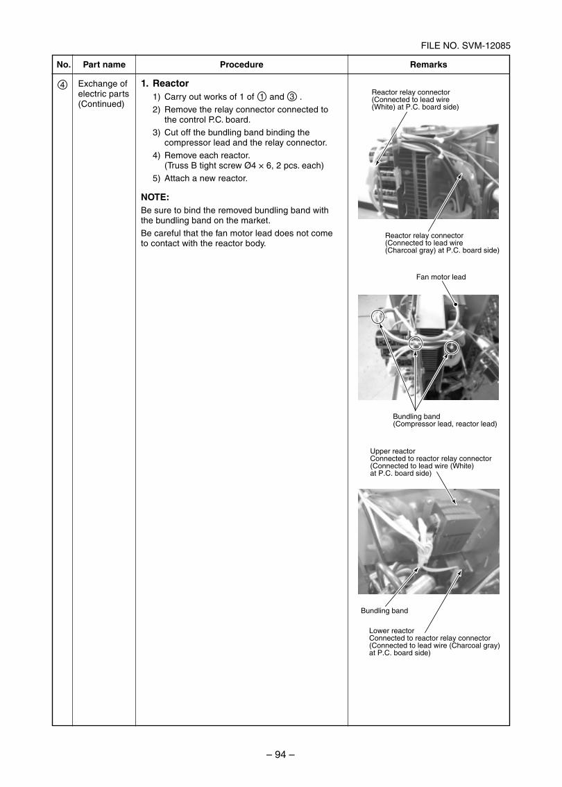
– 94 –
FILE NO. SVM-12085
No.
4
Part name
Exchange ofelectric parts(Continued)
Procedure
1. Reactor1) Carry out works of 1 of 1 and 3 .
2) Remove the relay connector connected tothe control P.C. board.
3) Cut off the bundling band binding thecompressor lead and the relay connector.
4) Remove each reactor.(Truss B tight screw Ø4 × 6, 2 pcs. each)
5) Attach a new reactor.
NOTE:Be sure to bind the removed bundling band withthe bundling band on the market.
Be careful that the fan motor lead does not cometo contact with the reactor body.
Remarks
Reactor relay connector(Connected to lead wire (White) at P.C. board side)
Reactor relay connector(Connected to lead wire (Charcoal gray) at P.C. board side)
Fan motor lead
Bundling band(Compressor lead, reactor lead)
Upper reactorConnected to reactor relay connector (Connected to lead wire (White) at P.C. board side)
Bundling band
Lower reactorConnected to reactor relay connector (Connected to lead wire (Charcoal gray) at P.C. board side)
SVM-12085_051-114.indd 94SVM-12085_051-114.indd 94 12/06/12 11:15 AM12/06/12 11:15 AM
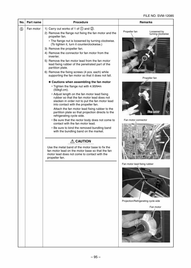
– 95 –
FILE NO. SVM-12085
No.
5
Part name
Fan motor
Procedure
1) Carry out works of 1 of 1 and 2 .
2) Remove the flange nut fixing the fan motor and thepropeller fan.
∗ The flange nut is loosened by turning clockwise.(To tighten it, turn it counterclockwise.)
3) Remove the propeller fan.
4) Remove the connector for fan motor from theinverter.
5) Remove the fan motor lead from the fan motorlead fixing rubber of the penetrated part of thepartition plate.
6) Remove the fixing screws (4 pcs. each) whilesupporting the fan motor so that it does not fall.
✻✻✻✻✻ Cautions when assembling the fan motor∗ Tighten the flange nut with 4.95N m
(50kgf.cm).
∗ Adjust length on the fan motor lead fixingrubber so that the fan motor lead does notslacken in order not to put the fan motor leadinto contact with the propeller fan.
Attach the fan motor lead fixing rubber to thepartition plate so that projection directs to therefrigerating cycle side.
∗ Be sure that the rector body does not come tocontact with the fan motor lead.
∗ Be sure to bind the removed bundling bandwith the bundling band on the market.
CAUTION
Use the metal band of the motor base to fix thefan motor lead on the motor base so that the fanmotor lead does not come to contact with thepropeller fan.
Remarks
Fan motor
Fan motor lead fixing rubber
Projection/Refrigerating cycle side
Propeller fan
Flange nut
Fan motor connector
Inverter
Propeller fan
Fan motor
Loosened by turning clockwise
Flange nut
Fan motor
Inverter
SVM-12085_051-114.indd 95SVM-12085_051-114.indd 95 12/06/12 11:15 AM12/06/12 11:15 AM
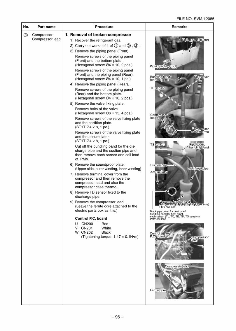
– 96 –
FILE NO. SVM-12085
No.
6
Part name
CompressorCompressor lead
Procedure
1. Removal of broken compressor1) Recover the refrigerant gas.
2) Carry out works of 1 of 1 and 2 , 3 .
3) Remove the piping panel (Front).
Remove screws of the piping panel(Front) and the bottom plate.(Hexagonal screw Ø4 × 10, 2 pcs.)
Remove screws of the piping panel(Front) and the piping panel (Rear).(Hexagonal screw Ø4 × 10, 1 pc.)
4) Remove the piping panel (Rear).
Remove screws of the piping panel(Rear) and the bottom plate.(Hexagonal screw Ø4 × 10, 2 pcs.)
5) Remove the valve fixing plate.
Remove bolts of the valve.(Hexagonal screw Ø6 × 15, 4 pcs.)
Remove screws of the valve fixing plateand the partition plate.(ST1T Ø4 × 8, 1 pc.)
Remove screws of the valve fixing plateand the accumulator.(ST1T Ø4 × 8, 1 pc.)
Cut off the bundling band for the dis-charge pipe and the suction pipe andthen remove each sensor and coil leadof PMV.
6) Remove the soundproof plate.(Upper side, outer winding, inner winding)
7) Remove terminal cover from thecompressor and then remove thecompressor lead and also thecompressor case thermo.
8) Remove TD sensor fixed to thedischarge pipe.
9) Remove the compressor lead.(Leave the ferrite core attached to theelectric parts box as it is.)
Control P.C. boardU : CN200 RedV : CN201 WhiteW : CN202 Black
(Tightening torque: 1.47 ± 0.1N m)
Remarks
Compressor lead
Ferrite core
Compressor lead
Ferrite core
ControlP.C. board Compressor
lead
ControlP.C. board Compressor
lead
Black pipe cover for heat proof, bundling band for heat proof, each sensor (TL, TO, TE, TD, TS sensors)PMV coil lead
Bundling band for heat proof
TD sensor
Compressorlead
Pipe cover
Compressorcase thermo
Bundling band for heat proof
TD sensor
Compressorlead
Pipe cover
Compressorcase thermo
Pipe cover, bundling band
Discharge pipe
TS sensor Pipe cover, bundling band
TS sensor
Suction pipe
Accumulator
Pipe cover, bundling band, each sensor (TL, TO, TE, TD, TS sensors)PMV coil lead
Pipe cover, bundling band, each sensor (TL, TO, TE, TD, TS sensors)PMV coil lead
Discharge pipeSuction pipe
Accumulator
Piping panel (Rear)
Piping panel (Front)
Piping panel (Rear)
Piping panel (Front)
SVM-12085_051-114.indd 96SVM-12085_051-114.indd 96 12/06/12 11:15 AM12/06/12 11:15 AM
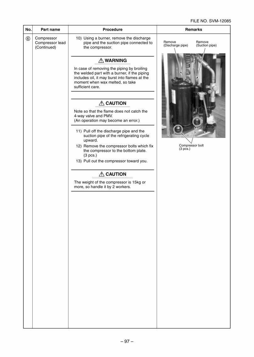
– 97 –
FILE NO. SVM-12085
No.
6
Part name
CompressorCompressor lead(Continued)
Procedure
10) Using a burner, remove the dischargepipe and the suction pipe connected tothe compressor.
WARNING
In case of removing the piping by broilingthe welded part with a burner, if the pipingincludes oil, it may burst into flames at themoment when wax melted, so takesufficient care.
CAUTION
Note so that the flame does not catch the4-way valve and PMV.(An operation may become an error.)
11) Pull off the discharge pipe and thesuction pipe of the refrigerating cycleupward.
12) Remove the compressor bolts which fixthe compressor to the bottom plate.(3 pcs.)
13) Pull out the compressor toward you.
X CAUTIONX
The weight of the compressor is 15kg ormore, so handle it by 2 workers.
Remarks
Remove(Discharge pipe)
Remove(Suction pipe)
Compressor bolt(3 pcs.)
SVM-12085_051-114.indd 97SVM-12085_051-114.indd 97 12/06/12 11:15 AM12/06/12 11:15 AM
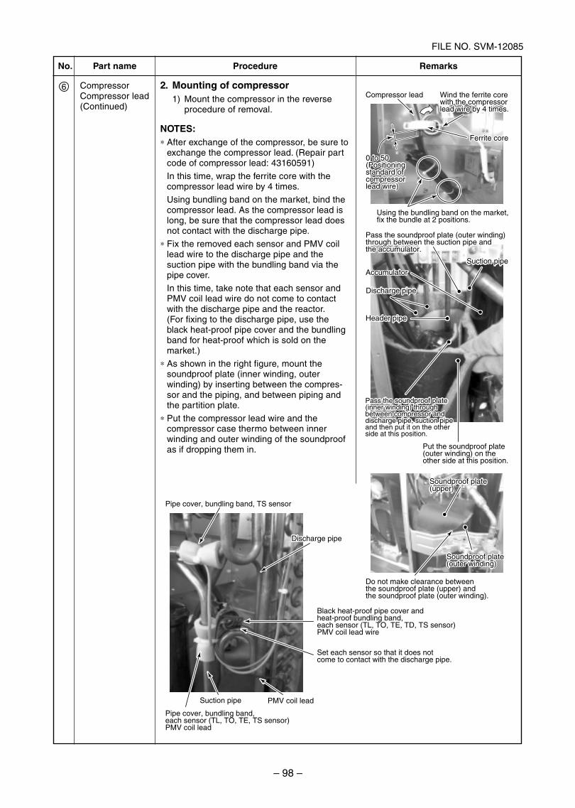
– 98 –
FILE NO. SVM-12085
Pipe cover, bundling band,each sensor (TL, TO, TE, TS sensor)PMV coil lead
Suction pipe
Pipe cover, bundling band, TS sensor
Compressor lead
Pass the soundproof plate (outer winding) through between the suction pipe and the accumulator.
Do not make clearance between the soundproof plate (upper) and the soundproof plate (outer winding).
Put the soundproof plate (outer winding) on the other side at this position.
Soundproof plate (upper)
Soundproof plate (outer winding)
Soundproof plate (upper)
Soundproof plate (outer winding)
Accumulator
Header pipe
0 to 50(Positioningstandard of compressorlead wire)
Ferrite core
Using the bundling band on the market, fix the bundle at 2 positions.
Wind the ferrite core with the compressor lead wire by 4 times.
0 to 50(Positioningstandard of compressorlead wire)
Ferrite core
Wind the ferrite core with the compressor lead wire by 4 times.
Suction pipe
Pass the soundproof plate (outer winding) through between the suction pipe and the accumulator.
Pass the soundproof plate (inner winding) through between compressor and discharge pipe, suction pipe and then put it on the other side at this position.
Accumulator
Discharge pipeDischarge pipe
Header pipe
Suction pipe
Discharge pipeDischarge pipe
Black heat-proof pipe cover and heat-proof bundling band,each sensor (TL, TO, TE, TD, TS sensor)PMV coil lead wire
Set each sensor so that it does not come to contact with the discharge pipe.
PMV coil lead
Pass the soundproof plate (inner winding) through between compressor and discharge pipe, suction pipe and then put it on the other side at this position.
No.
6
Part name
CompressorCompressor lead(Continued)
Procedure
2. Mounting of compressor1) Mount the compressor in the reverse
procedure of removal.
NOTES:∗ After exchange of the compressor, be sure to
exchange the compressor lead. (Repair partcode of compressor lead: 43160591)
In this time, wrap the ferrite core with thecompressor lead wire by 4 times.
Using bundling band on the market, bind thecompressor lead. As the compressor lead islong, be sure that the compressor lead doesnot contact with the discharge pipe.
∗ Fix the removed each sensor and PMV coillead wire to the discharge pipe and thesuction pipe with the bundling band via thepipe cover.
In this time, take note that each sensor andPMV coil lead wire do not come to contactwith the discharge pipe and the reactor.(For fixing to the discharge pipe, use theblack heat-proof pipe cover and the bundlingband for heat-proof which is sold on themarket.)
∗ As shown in the right figure, mount thesoundproof plate (inner winding, outerwinding) by inserting between the compres-sor and the piping, and between piping andthe partition plate.
∗ Put the compressor lead wire and thecompressor case thermo between innerwinding and outer winding of the soundproofas if dropping them in.
Remarks
SVM-12085_051-114.indd 98SVM-12085_051-114.indd 98 12/06/12 11:15 AM12/06/12 11:15 AM
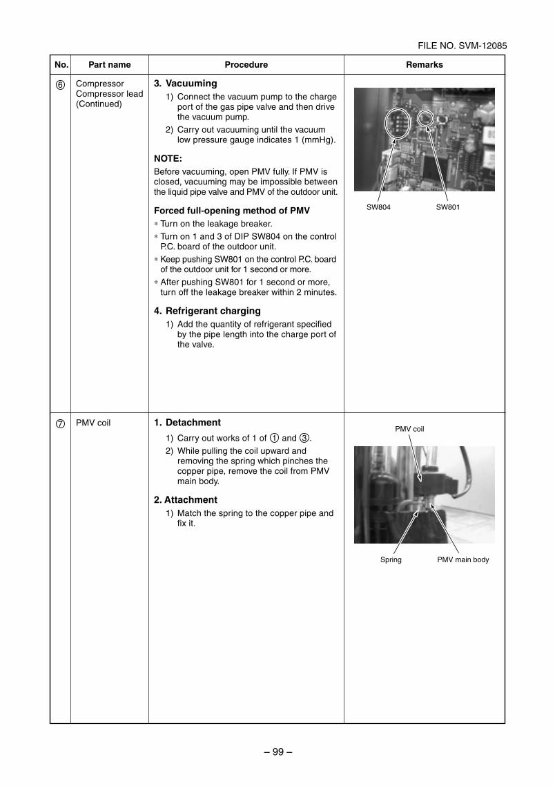
– 99 –
FILE NO. SVM-12085
No.
6
Part name
CompressorCompressor lead(Continued)
Procedure
3. Vacuuming1) Connect the vacuum pump to the charge
port of the gas pipe valve and then drivethe vacuum pump.
2) Carry out vacuuming until the vacuumlow pressure gauge indicates 1 (mmHg).
NOTE:Before vacuuming, open PMV fully. If PMV isclosed, vacuuming may be impossible betweenthe liquid pipe valve and PMV of the outdoor unit.
Forced full-opening method of PMV∗ Turn on the leakage breaker.
∗ Turn on 1 and 3 of DIP SW804 on the controlP.C. board of the outdoor unit.
∗ Keep pushing SW801 on the control P.C. boardof the outdoor unit for 1 second or more.
∗ After pushing SW801 for 1 second or more,turn off the leakage breaker within 2 minutes.
4. Refrigerant charging1) Add the quantity of refrigerant specified
by the pipe length into the charge port ofthe valve.
Remarks
1. Detachment
1) Carry out works of 1 of 1 and 3 .
2) While pulling the coil upward andremoving the spring which pinches thecopper pipe, remove the coil from PMVmain body.
2. Attachment1) Match the spring to the copper pipe and
fix it.
PMV coil7
SW804 SW801
PMV coil
Spring PMV main body
SVM-12085_051-114.indd 99SVM-12085_051-114.indd 99 12/06/12 11:15 AM12/06/12 11:15 AM
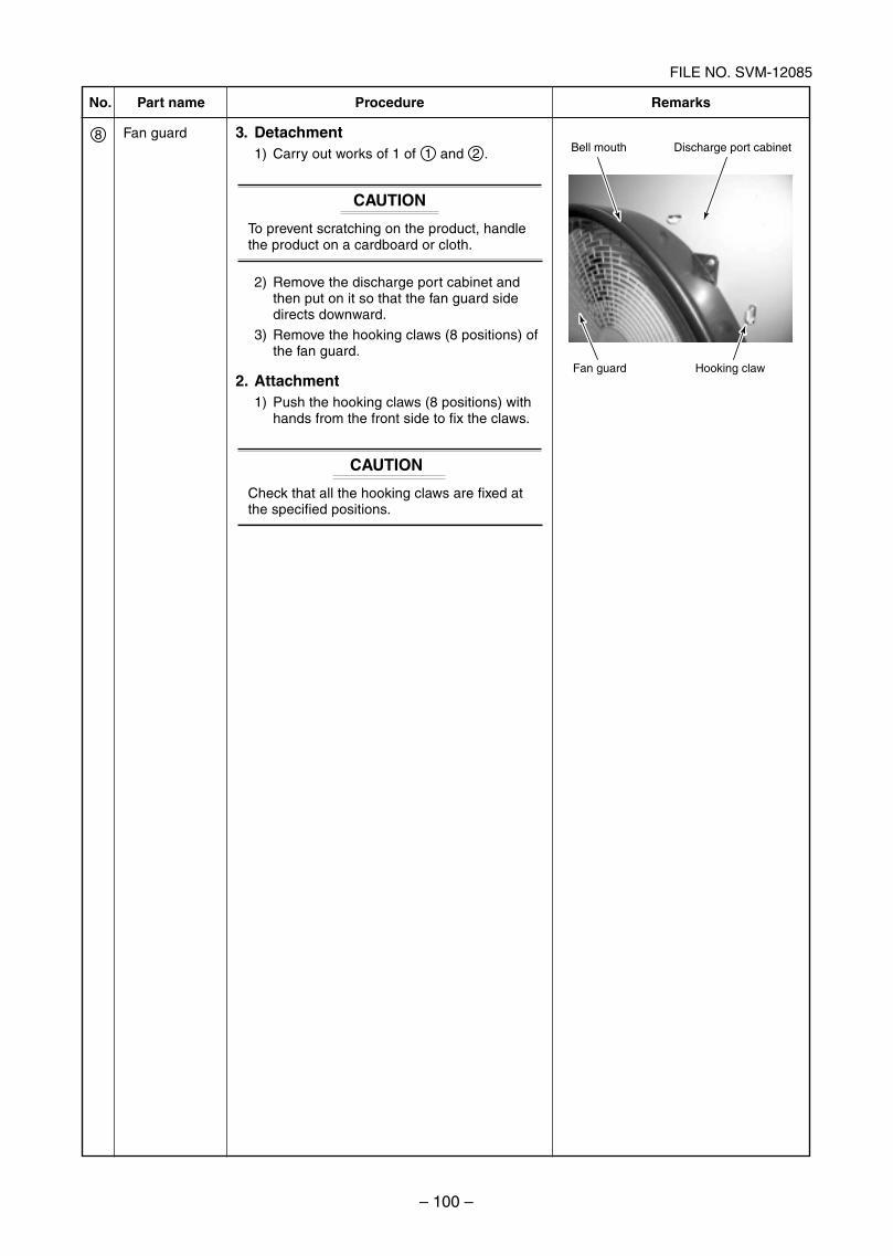
– 100 –
FILE NO. SVM-12085
No.
8
Part name
Fan guard
Procedure
3. Detachment1) Carry out works of 1 of 1 and 2 .
CAUTION
To prevent scratching on the product, handlethe product on a cardboard or cloth.
2) Remove the discharge port cabinet andthen put on it so that the fan guard sidedirects downward.
3) Remove the hooking claws (8 positions) ofthe fan guard.
2. Attachment1) Push the hooking claws (8 positions) with
hands from the front side to fix the claws.
CAUTIONX
Check that all the hooking claws are fixed atthe specified positions.
Remarks
Bell mouth Discharge port cabinet
Fan guard Hooking claw
SVM-12085_051-114.indd 100SVM-12085_051-114.indd 100 12/06/12 11:15 AM12/06/12 11:15 AM
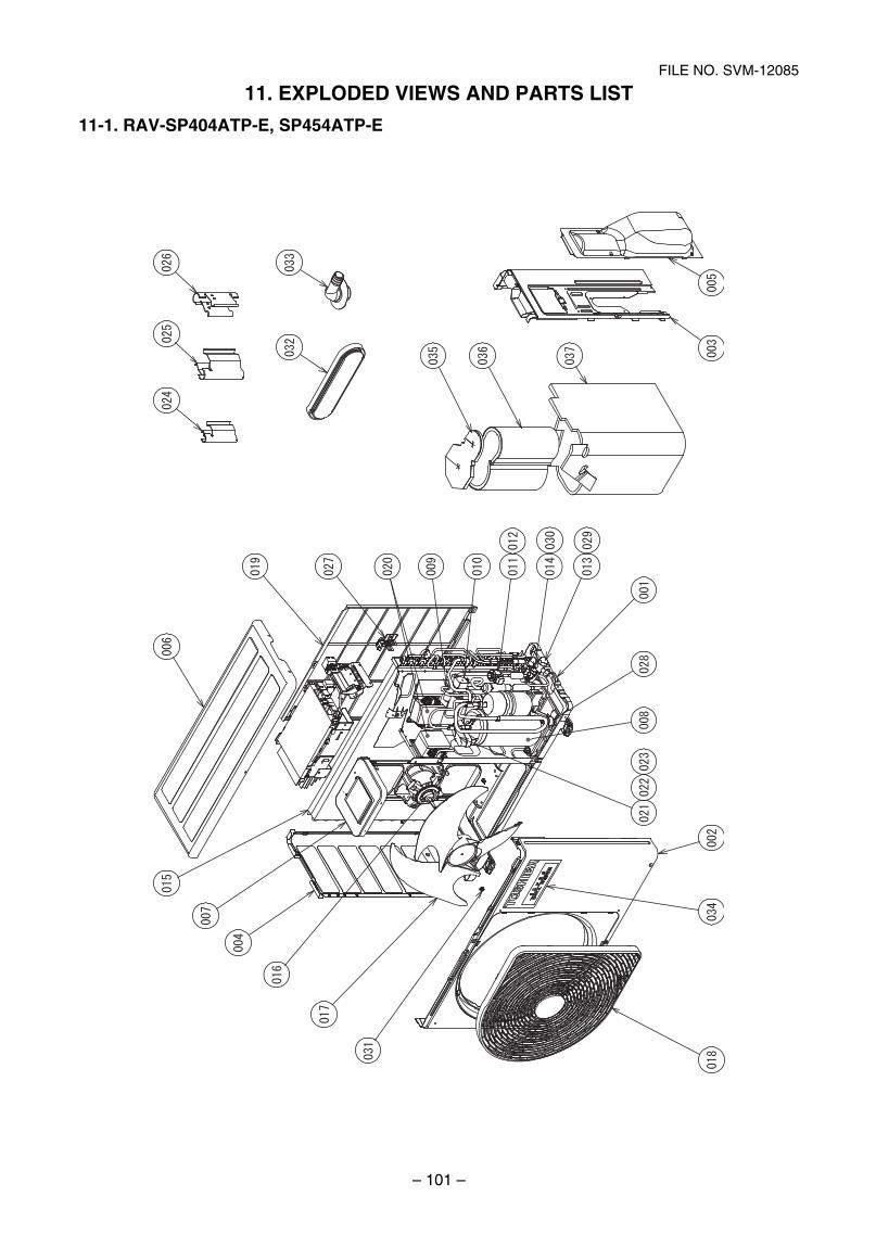
– 101 –
FILE NO. SVM-12085
11. EXPLODED VIEWS AND PARTS LIST
11-1. RAV-SP404ATP-E, SP454ATP-E
SVM-12085_051-114.indd 101SVM-12085_051-114.indd 101 12/06/12 11:15 AM12/06/12 11:15 AM
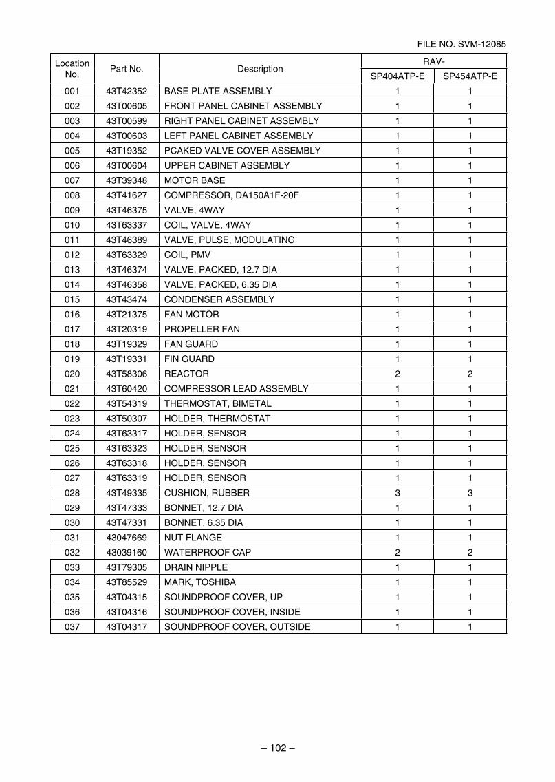
– 102 –
FILE NO. SVM-12085
LocationNo.
Part No. DescriptionRAV-
SP404ATP-E SP454ATP-E
001 43T42352 BASE PLATE ASSEMBLY 1 1
002 43T00605 FRONT PANEL CABINET ASSEMBLY 1 1
003 43T00599 RIGHT PANEL CABINET ASSEMBLY 1 1
004 43T00603 LEFT PANEL CABINET ASSEMBLY 1 1
005 43T19352 PCAKED VALVE COVER ASSEMBLY 1 1
006 43T00604 UPPER CABINET ASSEMBLY 1 1
007 43T39348 MOTOR BASE 1 1
008 43T41627 COMPRESSOR, DA150A1F-20F 1 1
009 43T46375 VALVE, 4WAY 1 1
010 43T63337 COIL, VALVE, 4WAY 1 1
011 43T46389 VALVE, PULSE, MODULATING 1 1
012 43T63329 COIL, PMV 1 1
013 43T46374 VALVE, PACKED, 12.7 DIA 1 1
014 43T46358 VALVE, PACKED, 6.35 DIA 1 1
015 43T43474 CONDENSER ASSEMBLY 1 1
016 43T21375 FAN MOTOR 1 1
017 43T20319 PROPELLER FAN 1 1
018 43T19329 FAN GUARD 1 1
019 43T19331 FIN GUARD 1 1
020 43T58306 REACTOR 2 2
021 43T60420 COMPRESSOR LEAD ASSEMBLY 1 1
022 43T54319 THERMOSTAT, BIMETAL 1 1
023 43T50307 HOLDER, THERMOSTAT 1 1
024 43T63317 HOLDER, SENSOR 1 1
025 43T63323 HOLDER, SENSOR 1 1
026 43T63318 HOLDER, SENSOR 1 1
027 43T63319 HOLDER, SENSOR 1 1
028 43T49335 CUSHION, RUBBER 3 3
029 43T47333 BONNET, 12.7 DIA 1 1
030 43T47331 BONNET, 6.35 DIA 1 1
031 43047669 NUT FLANGE 1 1
032 43039160 WATERPROOF CAP 2 2
033 43T79305 DRAIN NIPPLE 1 1
034 43T85529 MARK, TOSHIBA 1 1
035 43T04315 SOUNDPROOF COVER, UP 1 1
036 43T04316 SOUNDPROOF COVER, INSIDE 1 1
037 43T04317 SOUNDPROOF COVER, OUTSIDE 1 1
SVM-12085_051-114.indd 102SVM-12085_051-114.indd 102 12/06/12 11:15 AM12/06/12 11:15 AM
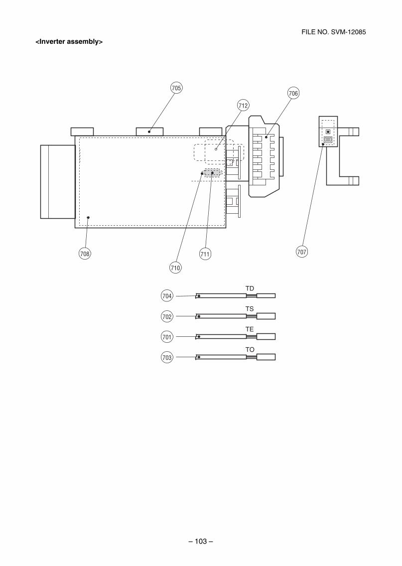
– 103 –
FILE NO. SVM-12085
<Inverter assembly>
TD
TS
TE
TO
705
708
710
704
702
701
703
711 707
712
706
SVM-12085_051-114.indd 103SVM-12085_051-114.indd 103 12/06/12 11:15 AM12/06/12 11:15 AM
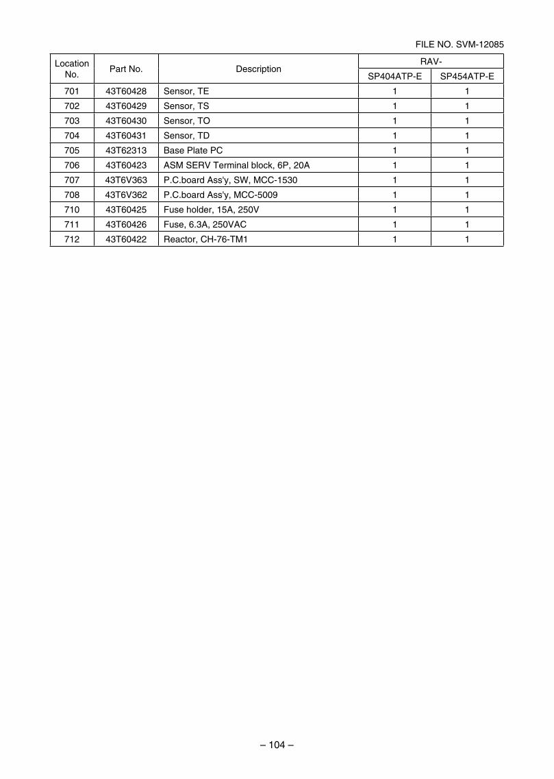
– 104 –
FILE NO. SVM-12085
LocationNo.
Part No. DescriptionRAV-
SP404ATP-E SP454ATP-E
701 43T60428 Sensor, TE 1 1
702 43T60429 Sensor, TS 1 1
703 43T60430 Sensor, TO 1 1
704 43T60431 Sensor, TD 1 1
705 43T62313 Base Plate PC 1 1
706 43T60423 ASM SERV Terminal block, 6P, 20A 1 1
707 43T6V363 P.C.board Ass'y, SW, MCC-1530 1 1
708 43T6V362 P.C.board Ass'y, MCC-5009 1 1
710 43T60425 Fuse holder, 15A, 250V 1 1
711 43T60426 Fuse, 6.3A, 250VAC 1 1
712 43T60422 Reactor, CH-76-TM1 1 1
SVM-12085_051-114.indd 104SVM-12085_051-114.indd 104 12/06/12 11:15 AM12/06/12 11:15 AM
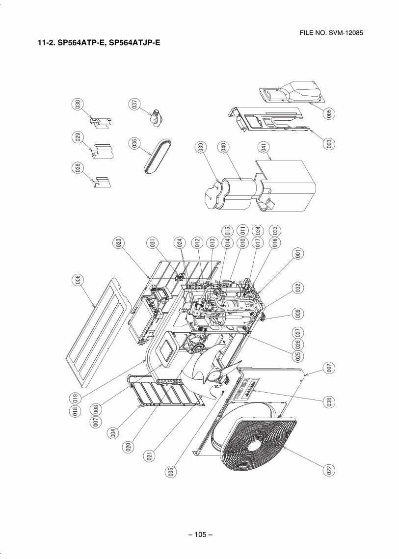
– 105 –
FILE NO. SVM-12085
11-2. SP564ATP-E, SP564ATJP-E
SVM-12085_051-114.indd 105SVM-12085_051-114.indd 105 12/06/12 11:15 AM12/06/12 11:15 AM
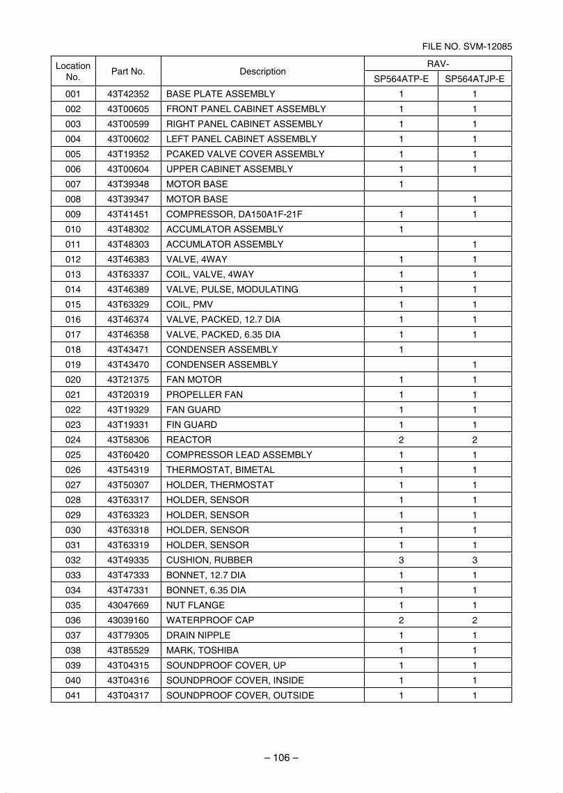
– 106 –
FILE NO. SVM-12085
LocationNo.
Part No. DescriptionRAV-
SP564ATP-E SP564ATJP-E
001 43T42352 BASE PLATE ASSEMBLY 1 1
002 43T00605 FRONT PANEL CABINET ASSEMBLY 1 1
003 43T00599 RIGHT PANEL CABINET ASSEMBLY 1 1
004 43T00602 LEFT PANEL CABINET ASSEMBLY 1 1
005 43T19352 PCAKED VALVE COVER ASSEMBLY 1 1
006 43T00604 UPPER CABINET ASSEMBLY 1 1
007 43T39348 MOTOR BASE 1
008 43T39347 MOTOR BASE 1
009 43T41451 COMPRESSOR, DA150A1F-21F 1 1
010 43T48302 ACCUMLATOR ASSEMBLY 1
011 43T48303 ACCUMLATOR ASSEMBLY 1
012 43T46383 VALVE, 4WAY 1 1
013 43T63337 COIL, VALVE, 4WAY 1 1
014 43T46389 VALVE, PULSE, MODULATING 1 1
015 43T63329 COIL, PMV 1 1
016 43T46374 VALVE, PACKED, 12.7 DIA 1 1
017 43T46358 VALVE, PACKED, 6.35 DIA 1 1
018 43T43471 CONDENSER ASSEMBLY 1
019 43T43470 CONDENSER ASSEMBLY 1
020 43T21375 FAN MOTOR 1 1
021 43T20319 PROPELLER FAN 1 1
022 43T19329 FAN GUARD 1 1
023 43T19331 FIN GUARD 1 1
024 43T58306 REACTOR 2 2
025 43T60420 COMPRESSOR LEAD ASSEMBLY 1 1
026 43T54319 THERMOSTAT, BIMETAL 1 1
027 43T50307 HOLDER, THERMOSTAT 1 1
028 43T63317 HOLDER, SENSOR 1 1
029 43T63323 HOLDER, SENSOR 1 1
030 43T63318 HOLDER, SENSOR 1 1
031 43T63319 HOLDER, SENSOR 1 1
032 43T49335 CUSHION, RUBBER 3 3
033 43T47333 BONNET, 12.7 DIA 1 1
034 43T47331 BONNET, 6.35 DIA 1 1
035 43047669 NUT FLANGE 1 1
036 43039160 WATERPROOF CAP 2 2
037 43T79305 DRAIN NIPPLE 1 1
038 43T85529 MARK, TOSHIBA 1 1
039 43T04315 SOUNDPROOF COVER, UP 1 1
040 43T04316 SOUNDPROOF COVER, INSIDE 1 1
041 43T04317 SOUNDPROOF COVER, OUTSIDE 1 1
SVM-12085_051-114.indd 106SVM-12085_051-114.indd 106 12/06/12 11:15 AM12/06/12 11:15 AM
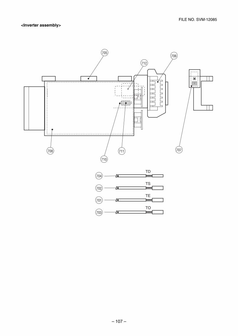
– 107 –
FILE NO. SVM-12085
TD
TS
TE
TO
705
708
710
704
702
701
703
711 707
712
706
<Inverter assembly>
SVM-12085_051-114.indd 107SVM-12085_051-114.indd 107 12/06/12 11:15 AM12/06/12 11:15 AM
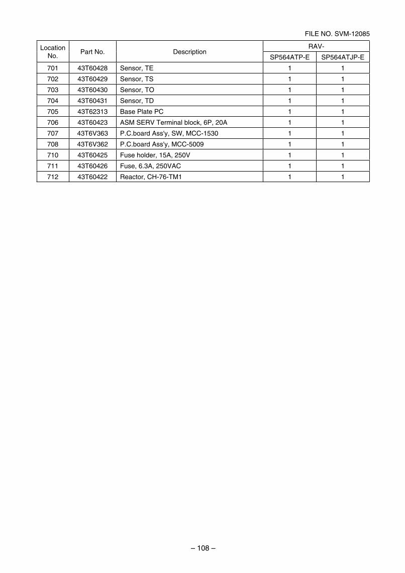
– 108 –
FILE NO. SVM-12085
LocationNo.
Part No. DescriptionRAV-
SP564ATP-E SP564ATJP-E
701 43T60428 Sensor, TE 1 1
702 43T60429 Sensor, TS 1 1
703 43T60430 Sensor, TO 1 1
704 43T60431 Sensor, TD 1 1
705 43T62313 Base Plate PC 1 1
706 43T60423 ASM SERV Terminal block, 6P, 20A 1 1
707 43T6V363 P.C.board Ass'y, SW, MCC-1530 1 1
708 43T6V362 P.C.board Ass'y, MCC-5009 1 1
710 43T60425 Fuse holder, 15A, 250V 1 1
711 43T60426 Fuse, 6.3A, 250VAC 1 1
712 43T60422 Reactor, CH-76-TM1 1 1
SVM-12085_051-114.indd 108SVM-12085_051-114.indd 108 12/06/12 11:15 AM12/06/12 11:15 AM
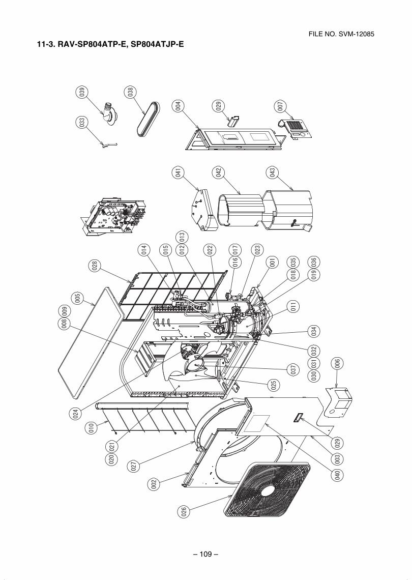
– 109 –
FILE NO. SVM-12085
11-3. RAV-SP804ATP-E, SP804ATJP-E
SVM-12085_051-114.indd 109SVM-12085_051-114.indd 109 12/06/12 11:15 AM12/06/12 11:15 AM
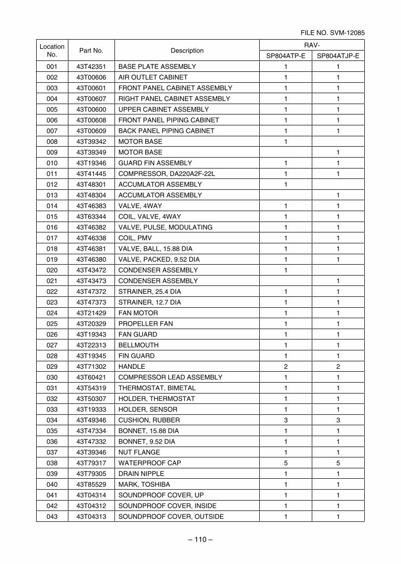
– 110 –
FILE NO. SVM-12085
LocationNo.
Part No. DescriptionRAV-
SP804ATP-E SP804ATJP-E
001 43T42351 BASE PLATE ASSEMBLY 1 1
002 43T00606 AIR OUTLET CABINET 1 1
003 43T00601 FRONT PANEL CABINET ASSEMBLY 1 1
004 43T00607 RIGHT PANEL CABINET ASSEMBLY 1 1
005 43T00600 UPPER CABINET ASSEMBLY 1 1
006 43T00608 FRONT PANEL PIPING CABINET 1 1
007 43T00609 BACK PANEL PIPING CABINET 1 1
008 43T39342 MOTOR BASE 1
009 43T39349 MOTOR BASE 1
010 43T19346 GUARD FIN ASSEMBLY 1 1
011 43T41445 COMPRESSOR, DA220A2F-22L 1 1
012 43T48301 ACCUMLATOR ASSEMBLY 1
013 43T48304 ACCUMLATOR ASSEMBLY 1
014 43T46383 VALVE, 4WAY 1 1
015 43T63344 COIL, VALVE, 4WAY 1 1
016 43T46382 VALVE, PULSE, MODULATING 1 1
017 43T46338 COIL, PMV 1 1
018 43T46381 VALVE, BALL, 15.88 DIA 1 1
019 43T46380 VALVE, PACKED, 9.52 DIA 1 1
020 43T43472 CONDENSER ASSEMBLY 1
021 43T43473 CONDENSER ASSEMBLY 1
022 43T47372 STRAINER, 25.4 DIA 1 1
023 43T47373 STRAINER, 12.7 DIA 1 1
024 43T21429 FAN MOTOR 1 1
025 43T20329 PROPELLER FAN 1 1
026 43T19343 FAN GUARD 1 1
027 43T22313 BELLMOUTH 1 1
028 43T19345 FIN GUARD 1 1
029 43T71302 HANDLE 2 2
030 43T60421 COMPRESSOR LEAD ASSEMBLY 1 1
031 43T54319 THERMOSTAT, BIMETAL 1 1
032 43T50307 HOLDER, THERMOSTAT 1 1
033 43T19333 HOLDER, SENSOR 1 1
034 43T49346 CUSHION, RUBBER 3 3
035 43T47334 BONNET, 15.88 DIA 1 1
036 43T47332 BONNET, 9.52 DIA 1 1
037 43T39346 NUT FLANGE 1 1
038 43T79317 WATERPROOF CAP 5 5
039 43T79305 DRAIN NIPPLE 1 1
040 43T85529 MARK, TOSHIBA 1 1
041 43T04314 SOUNDPROOF COVER, UP 1 1
042 43T04312 SOUNDPROOF COVER, INSIDE 1 1
043 43T04313 SOUNDPROOF COVER, OUTSIDE 1 1
SVM-12085_051-114.indd 110SVM-12085_051-114.indd 110 12/06/12 11:15 AM12/06/12 11:15 AM
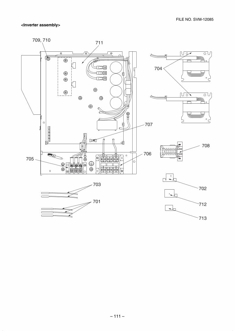
– 111 –
FILE NO. SVM-12085
<Inverter assembly>
1 2 3
705
709, 710 711
707
704
706
703
701
708
702
712
713
SVM-12085_051-114.indd 111SVM-12085_051-114.indd 111 12/06/12 11:15 AM12/06/12 11:15 AM
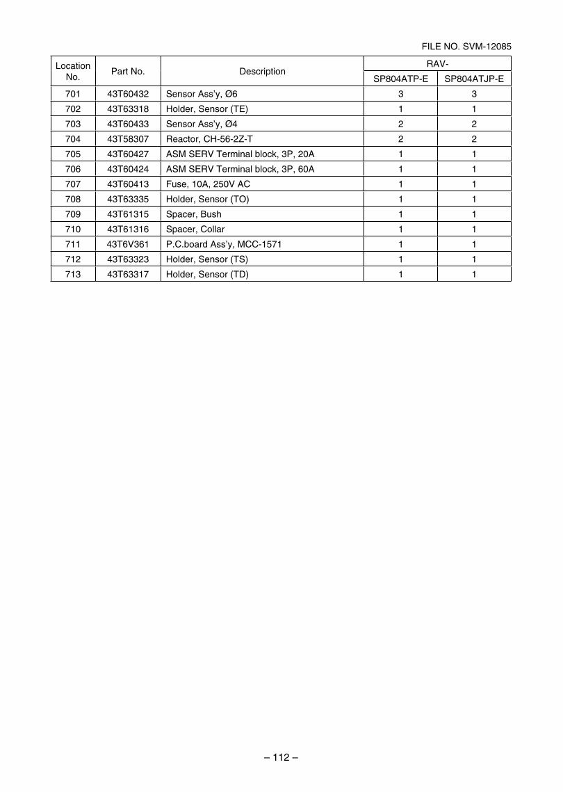
– 112 –
FILE NO. SVM-12085
LocationNo.
Part No. DescriptionRAV-
SP804ATP-E SP804ATJP-E
701 43T60432 Sensor Ass’y, Ø6 3 3
702 43T63318 Holder, Sensor (TE) 1 1
703 43T60433 Sensor Ass’y, Ø4 2 2
704 43T58307 Reactor, CH-56-2Z-T 2 2
705 43T60427 ASM SERV Terminal block, 3P, 20A 1 1
706 43T60424 ASM SERV Terminal block, 3P, 60A 1 1
707 43T60413 Fuse, 10A, 250V AC 1 1
708 43T63335 Holder, Sensor (TO) 1 1
709 43T61315 Spacer, Bush 1 1
710 43T61316 Spacer, Collar 1 1
711 43T6V361 P.C.board Ass’y, MCC-1571 1 1
712 43T63323 Holder, Sensor (TS) 1 1
713 43T63317 Holder, Sensor (TD) 1 1
SVM-12085_051-114.indd 112SVM-12085_051-114.indd 112 12/06/12 11:15 AM12/06/12 11:15 AM
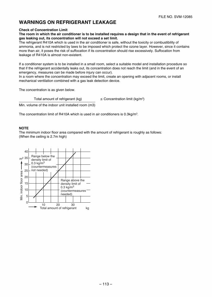
– 113 –
FILE NO. SVM-12085
WARNINGS ON REFRIGERANT LEAKAGECheck of Concentration LimitThe room in which the air conditioner is to be installed requires a design that in the event of refrigerant gas leaking out, its concentration will not exceed a set limit.The refrigerant R410A which is used in the air conditioner is safe, without the toxicity or combustibility of ammonia, and is not restricted by laws to be imposed which protect the ozone layer. However, since it contains more than air, it poses the risk of suffocation if its concentration should rise excessively. Suffocation from leakage of R410A is almost non-existent.
If a conditioner system is to be installed in a small room, select a suitable model and installation procedure so that if the refrigerant accidentally leaks out, its concentration does not reach the limit (and in the event of an emergency, measures can be made before injury can occur).In a room where the concentration may exceed the limit, create an opening with adjacent rooms, or install mechanical ventilation combined with a gas leak detection device.
The concentration is as given below.
Total amount of refrigerant (kg) ≤ Concentration limit (kg/m3)
Min. volume of the indoor unit installed room (m3)
The concentration limit of R410A which is used in air conditioners is 0.3kg/m3.
NOTEThe minimum indoor floor area compared with the amount of refrigerant is roughly as follows:(When the ceiling is 2.7m high)
Range above the density limit of 0.3 kg/m3
(countermeasures needed)
40
m2 35
30
25
20
15
10
10Total amount of refrigerant
Min
. ind
oor
floor
are
a
20 30kg
5
0
Range below the density limit of 0.3 kg/m3
(countermeasures not needed)
SVM-12085_051-114.indd 113SVM-12085_051-114.indd 113 12/06/12 11:15 AM12/06/12 11:15 AM

TOSHIBA CARRIER (THAILAND) CO.,LTD.144/9 MOO 5, BANGKADI INDUSTRIAL PARK, TIVANON ROAD, TAMBOL BANGKADI,
AMPHUR MUANG, PATHUMTHANI 12000, THAILAND.
SVM-12085_051-114.indd 114SVM-12085_051-114.indd 114 12/06/12 11:15 AM12/06/12 11:15 AM