service doa no. beranových 65/666 sa-11 …pdf.aviapropeller.cz/sa-11.pdfthe technical content of...
TRANSCRIPT
The technical content of this document is approved under authority of DOA No. EASA.21J.072.
AVIA PROPELLER Ltd Beranových 65/666
199 00 Praha 9 Czech Republic
SERVICE ADVISORY SA-11
DOA No. EASA.21J.072
Office of Airworthiness Zbyněk Tvrdík Date: May 22, 2017
Prepared by: Pavel Demkovič Date: May 22, 2017
Page : 1 Pages : 13
SUBJECT: This document provides repair procedures of the Brush block assembly, and it: BRUSH ASSEMBLY REPLACEMENT BRUSH MODULE REPLACEMENT BRUSH REPLACEMENT CONTENTS: Page: I. GENERAL 1 II. NOMENCLATURE 1 III. LIST OF TOOLS 3 IV. BRUSH ASSEMBLY REPLACEMENT 4 V. BRUSH MODULE REPLACEMENT 6 VI. BRUSH REPLACEMENT 9 I. GENERAL
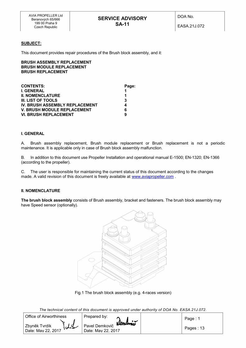
A. Brush assembly replacement, Brush module replacement or Brush replacement is not a periodic maintenance. It is applicable only in case of Brush block assembly malfunction. B. In addition to this document use Propeller Installation and operational manual E-1500; EN-1320; EN-1366 (according to the propeller). C. The user is responsible for maintaining the current status of this document according to the changes made. A valid revision of this document is freely available at www.aviapropeller.com . II. NOMENCLATURE The brush block assembly consists of Brush assembly, bracket and fasteners. The brush block assembly may have Speed sensor (optionally).
Fig.1 The brush block assembly (e.g. 4-races version)
The technical content of this document is approved under authority of DOA No. EASA.21J.072.
AVIA PROPELLER Ltd Beranových 65/666
199 00 Praha 9 Czech Republic
SERVICE ADVISORY SA-11
DOA No. EASA.21J.072
Office of Airworthiness Zbyněk Tvrdík Date: May 22, 2017
Prepared by: Pavel Demkovič Date: May 22, 2017
Page : 2 Pages : 13
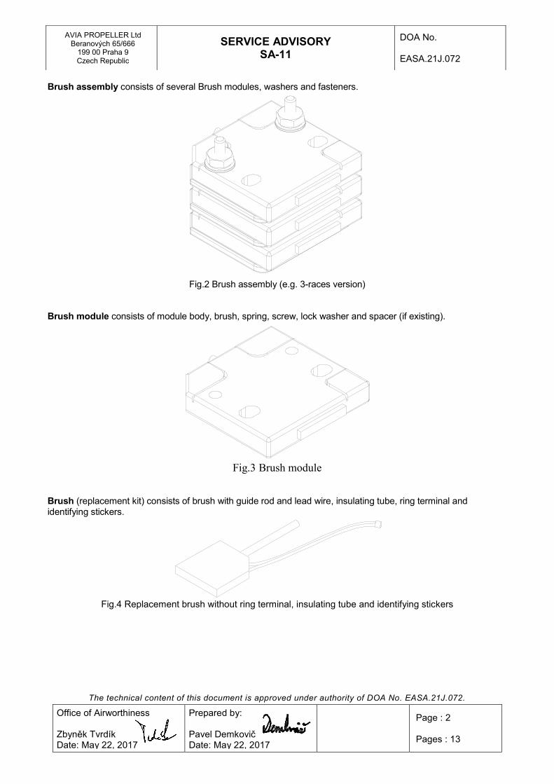
Brush assembly consists of several Brush modules, washers and fasteners.
Fig.2 Brush assembly (e.g. 3-races version)
Brush module consists of module body, brush, spring, screw, lock washer and spacer (if existing).
Fig.3 Brush module
Brush (replacement kit) consists of brush with guide rod and lead wire, insulating tube, ring terminal and identifying stickers.
Fig.4 Replacement brush without ring terminal, insulating tube and identifying stickers

The technical content of this document is approved under authority of DOA No. EASA.21J.072.
AVIA PROPELLER Ltd Beranových 65/666
199 00 Praha 9 Czech Republic
SERVICE ADVISORY SA-11
DOA No. EASA.21J.072
Office of Airworthiness Zbyněk Tvrdík Date: May 22, 2017
Prepared by: Pavel Demkovič Date: May 22, 2017
Page : 3 Pages : 13
III. LIST OF TOOLS
- Nippers for cutting off safety wire on the engine gear box and cutting off wire of the brush (for brush replacement)
- Wire pliers for screw locking with safety wire - 1x Spanner No.8mm and 1x ratchet with socket No.8 (or other suitable wrench – e.g. tubular socket
wrench) - 1x Cross screwdriver - type PH2 - 1x Torque wrench (with range from 0 Nm) with socket No.8 for tightening the brush assembly to the
bracket - Crimping tool for crimping the ring terminal - Rubber band for securing pressed brush, or e.g. paper adhesive tape
The technical content of this document is approved under authority of DOA No. EASA.21J.072.
AVIA PROPELLER Ltd Beranových 65/666
199 00 Praha 9 Czech Republic
SERVICE ADVISORY SA-11
DOA No. EASA.21J.072
Office of Airworthiness Zbyněk Tvrdík Date: May 22, 2017
Prepared by: Pavel Demkovič Date: May 22, 2017
Page : 4 Pages : 13
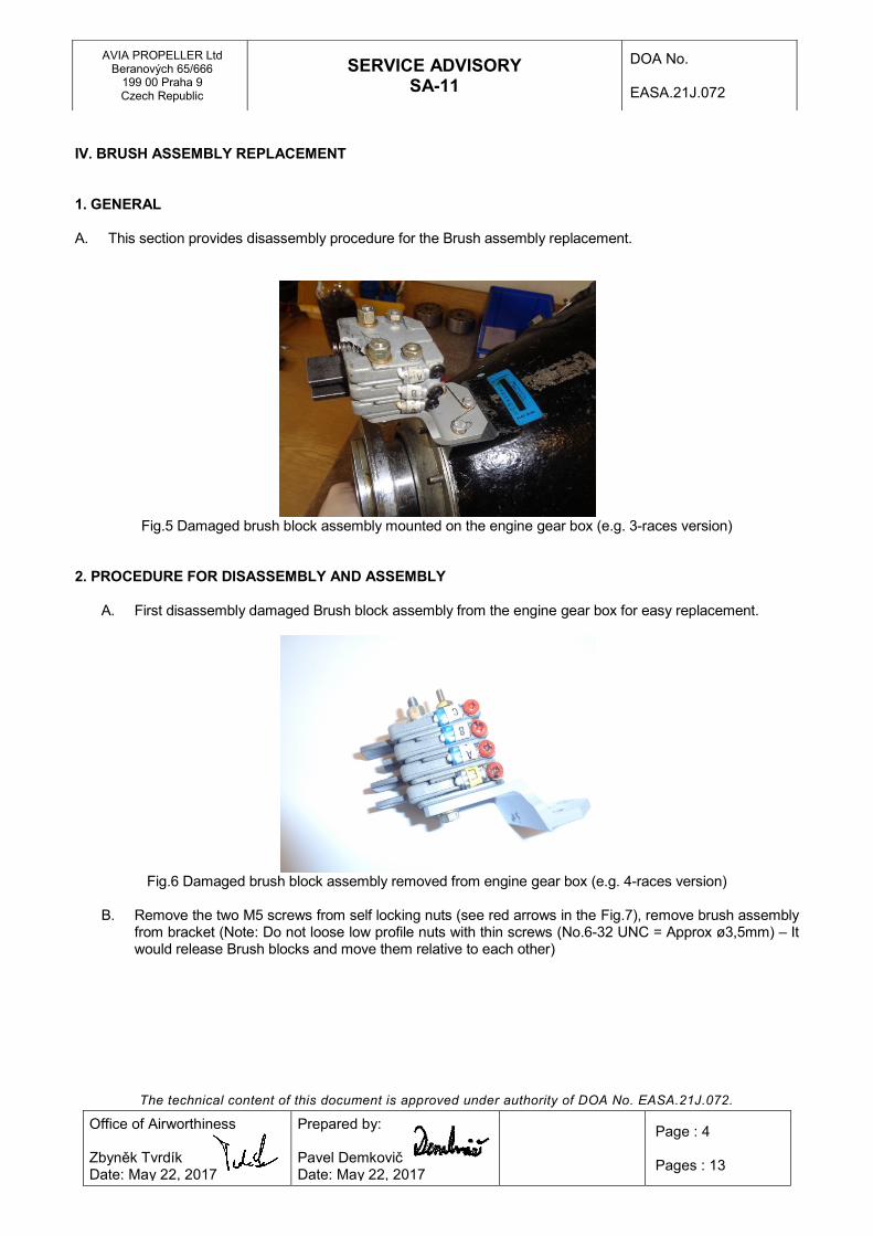
IV. BRUSH ASSEMBLY REPLACEMENT 1. GENERAL A. This section provides disassembly procedure for the Brush assembly replacement.
Fig.5 Damaged brush block assembly mounted on the engine gear box (e.g. 3-races version)
2. PROCEDURE FOR DISASSEMBLY AND ASSEMBLY
A. First disassembly damaged Brush block assembly from the engine gear box for easy replacement.
Fig.6 Damaged brush block assembly removed from engine gear box (e.g. 4-races version)
B. Remove the two M5 screws from self locking nuts (see red arrows in the Fig.7), remove brush assembly
from bracket (Note: Do not loose low profile nuts with thin screws (No.6-32 UNC = Approx ø3,5mm) – It would release Brush blocks and move them relative to each other)

The technical content of this document is approved under authority of DOA No. EASA.21J.072.
AVIA PROPELLER Ltd Beranových 65/666
199 00 Praha 9 Czech Republic
SERVICE ADVISORY SA-11
DOA No. EASA.21J.072
Office of Airworthiness Zbyněk Tvrdík Date: May 22, 2017
Prepared by: Pavel Demkovič Date: May 22, 2017
Page : 5 Pages : 13
Fig.7 Loose screws and nuts marked with red arrows for disassembly Brush block assembly
C. Install a new or repaired brush assembly on the original bracket using the original fasteners if it has
not been damaged. Do not fully tighten the screw connection and follow Installation and operation manual for your propeller – section Brush block installation.
Fig.8 New Brush assembly (for replacement) Fig.9 Used original console with fasteners
Fig.10 Brush block assembly with new brush assembly

The technical content of this document is approved under authority of DOA No. EASA.21J.072.
AVIA PROPELLER Ltd Beranových 65/666
199 00 Praha 9 Czech Republic
SERVICE ADVISORY SA-11
DOA No. EASA.21J.072
Office of Airworthiness Zbyněk Tvrdík Date: May 22, 2017
Prepared by: Pavel Demkovič Date: May 22, 2017
Page : 6 Pages : 13
V. BRUSH MODULE REPLACEMENT 1. GENERAL
A. This section provides disassembly procedure for the Brush module replacement.
Fig.11 Damaged 3-races Brush assembly Fig.12 Damaged 4-races Brush assembly
2. PROCEDURE FOR DISASSEMBLY AND ASSEMBLY
A. First disassembly damaged Brush assembly from Brush block assembly – see part IV. from this document.
B. Loose two screw connections (see red arrows on fig.13) and remove all damaged brush modules.
Fig.13 Loose two screw connections for disassembly Fig.14 Damaged Bush modules for replacement
the Brush assembly

The technical content of this document is approved under authority of DOA No. EASA.21J.072.
AVIA PROPELLER Ltd Beranových 65/666
199 00 Praha 9 Czech Republic
SERVICE ADVISORY SA-11
DOA No. EASA.21J.072
Office of Airworthiness Zbyněk Tvrdík Date: May 22, 2017
Prepared by: Pavel Demkovič Date: May 22, 2017
Page : 7 Pages : 13
C. Damaged Brush modules can be replaced for same version – i.e. A for A („A“ – P/N 3E2011-15), B for B
(„B“ – P/N 3E2011-16) and C for C („C“ – P/N 3E2011-17), or universal P/N 3E2011-10 for any (then mark ring terminal with correct letter at identifying stickers).
Fig.15 New replacement Brush blocks „A“ „B“ „C“ Fig.16 New universal replacement Brush block P/N 3E2011-10
D. Remount Brush assembly as shown on Fig.17.
Fig.17 Brush assembly 4-races and/or 3-races
Position Name Marking (P/N)
1 Brush module 3E2011-15
2 Brush module 3E2011-16
3 Brush module 3E2011-17
4 Brush module 3E2011-15 or 3E2011-16 or 3E2011-17 or 3E2011-10
5 Washer 4E2218-4
6 Washer 4E2218-3
7 Screw MS24693-S36
8 Nut MS35649-262
9 Screw MS24693-S40
10 Washer NAS1149CN632R (AN960C6)
11 Serrated washer MS35333-37
12 Identifying shrink tube, or sticker -

The technical content of this document is approved under authority of DOA No. EASA.21J.072.
AVIA PROPELLER Ltd Beranových 65/666
199 00 Praha 9 Czech Republic
SERVICE ADVISORY SA-11
DOA No. EASA.21J.072
Office of Airworthiness Zbyněk Tvrdík Date: May 22, 2017
Prepared by: Pavel Demkovič Date: May 22, 2017
Page : 8 Pages : 13
Place the Brush assembly on the back of the Brush assembly and remount the Brush assembly on a flat and solid table with using cross screwdriver and spanner. See fig.18.
Fig.18 Remount Brush assembly on a flat and solid table
Note: When tightening the Brush assembly, make sure that the Brush assembly is firmly tightened but at the same time to prevent the screw joints from dropping and the destruction of the brush block body closest to the washers and nuts (see fig.14). Recommended tightening torque is 1Nm.
E. Remount Brush assembly according to IV. section in this document.
The technical content of this document is approved under authority of DOA No. EASA.21J.072.
AVIA PROPELLER Ltd Beranových 65/666
199 00 Praha 9 Czech Republic
SERVICE ADVISORY SA-11
DOA No. EASA.21J.072
Office of Airworthiness Zbyněk Tvrdík Date: May 22, 2017
Prepared by: Pavel Demkovič Date: May 22, 2017
Page : 9 Pages : 13
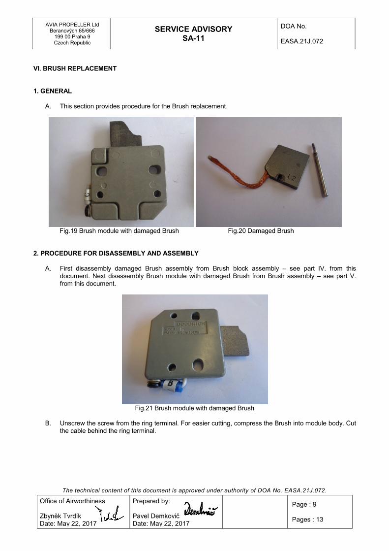
VI. BRUSH REPLACEMENT 1. GENERAL
A. This section provides procedure for the Brush replacement.
Fig.19 Brush module with damaged Brush Fig.20 Damaged Brush
2. PROCEDURE FOR DISASSEMBLY AND ASSEMBLY
A. First disassembly damaged Brush assembly from Brush block assembly – see part IV. from this document. Next disassembly Brush module with damaged Brush from Brush assembly – see part V. from this document.
Fig.21 Brush module with damaged Brush
B. Unscrew the screw from the ring terminal. For easier cutting, compress the Brush into module body. Cut
the cable behind the ring terminal.

The technical content of this document is approved under authority of DOA No. EASA.21J.072.
AVIA PROPELLER Ltd Beranových 65/666
199 00 Praha 9 Czech Republic
SERVICE ADVISORY SA-11
DOA No. EASA.21J.072
Office of Airworthiness Zbyněk Tvrdík Date: May 22, 2017
Prepared by: Pavel Demkovič Date: May 22, 2017
Page : 10 Pages : 13
Fig.22 Screw removing from the ring terminal Fig.23 Cut the cable behind the ring terminal
C. Remove the damaged Brush with rod including all broken parts. Only the spring must remain inside the
module body (see fig.25).
Fig.24 Module body with removed damaged Brush Fig.25 Empty module body with spring inside and cut-off ring terminal
D. Prepare a replacement Brush 3E2563-1 (supplier Goodrich).
Fig.26 Replacement Brush 3E2563-1

The technical content of this document is approved under authority of DOA No. EASA.21J.072.
AVIA PROPELLER Ltd Beranových 65/666
199 00 Praha 9 Czech Republic
SERVICE ADVISORY SA-11
DOA No. EASA.21J.072
Office of Airworthiness Zbyněk Tvrdík Date: May 22, 2017
Prepared by: Pavel Demkovič Date: May 22, 2017
Page : 11 Pages : 13
E. Slide insulating tube over brush lead so that the end of tubing almost contacts the brush. If the brush
lead is poorly sliding through the insulating tube, a thread may be used. Thread a cord through brush leads and stretch it through insulating tube. Now slide insulating tube over brush.
Fig.27 Brush with treaded insulating tube Fig.28 A brush with a thread for easier passage
of lead through the insulating tube
F. For easier installation form the lead of the Brush per fig.29. Then insert Brush into module body per fig.30. Ensure that the guide rod is in the spring and at the same time that the lead protrudes through the lead exit hole – see blue arrow in the fig.30.
Fig.29 Recommended forming of the lead Fig.30 Insert Brush into module body before installation

The technical content of this document is approved under authority of DOA No. EASA.21J.072.
AVIA PROPELLER Ltd Beranových 65/666
199 00 Praha 9 Czech Republic
SERVICE ADVISORY SA-11
DOA No. EASA.21J.072
Office of Airworthiness Zbyněk Tvrdík Date: May 22, 2017
Prepared by: Pavel Demkovič Date: May 22, 2017
Page : 12 Pages : 13
G. Fully compress the brush and secure it with a rubber band, or paper adhesive tape. Pull the lead out of
the exit hole until the maximum available lead length is external to the brush module and slide the tubing on the lead to within 3/16 inch (4,76mm) (if necessary, shorten the insulation tube) of the end of the bare wire (see fig.31).
Fig.31 Preparation of the brush wire to crimp the ring terminal
H. Install the ring terminal so that the end of the tubing is positioned inside the jacket of the ring terminal
and no bare wire is exposed (see fig.32). Crimp the ring terminal in place with crimping tool. After crimping degrease ring terminal with technical gasoline and mark it with correct indentifying sticker.
Fig.32 Position of the ring terminal Fig.33 Ring terminal degreasing
Fig.34 Ring terminal degreasing Fig.35 Mark with identifying sticker
The technical content of this document is approved under authority of DOA No. EASA.21J.072.
AVIA PROPELLER Ltd Beranových 65/666
199 00 Praha 9 Czech Republic
SERVICE ADVISORY SA-11
DOA No. EASA.21J.072
Office of Airworthiness Zbyněk Tvrdík Date: May 22, 2017
Prepared by: Pavel Demkovič Date: May 22, 2017
Page : 13 Pages : 13
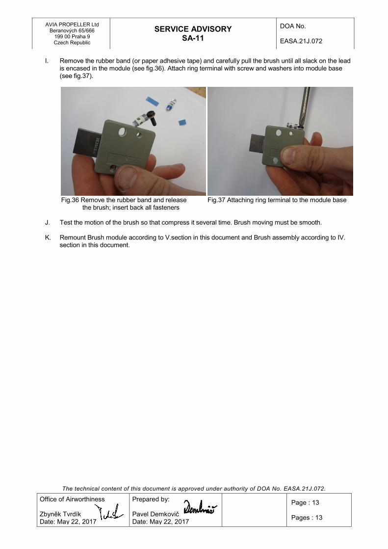
I. Remove the rubber band (or paper adhesive tape) and carefully pull the brush until all slack on the lead
is encased in the module (see fig.36). Attach ring terminal with screw and washers into module base (see fig.37).
Fig.36 Remove the rubber band and release Fig.37 Attaching ring terminal to the module base
the brush; insert back all fasteners
J. Test the motion of the brush so that compress it several time. Brush moving must be smooth.
K. Remount Brush module according to V.section in this document and Brush assembly according to IV. section in this document.