series 6300 installation & specification … this equipment has ... general troubleshooting...
TRANSCRIPT

A6300-7010
*A6300-7010*
Microframe Corporation 604 South 12th Street
Broken Arrow, OK 74012
Local: 918-258-4839 Toll Free: 800-635-3811
Website: www.microframecorp.com E-mail: [email protected]
SERIES 6300 INSTALLATION & SPECIFICATION GUIDE
Manual No. A6300-7010
Revision Date: 03/2016 Control: 1.7
Microframe Corporation 2
604 South 12th Street
Broken Arrow, OK 74012
800-635-3811
www.microframecorp.com Series 6300
Limited Warranty Agreement
Your Microframe System is warranted against failure due to defects in workmanship or material for a period of one (1) year from the date of purchase. Microframe Corporation will repair or replace any defective unit. Obvious abuse or mishandling of the unit is NOT covered by this warranty.
Merchandise Return
If your Unit does not work satisfactorily, please give us a call. We may be able to clear up the problem by phone. If it becomes necessary to return your Unit to the factory, please observe the following: 1. Call Microframe for an RMA number. This number authorizes you to return the product. 2.Place Unit in a sturdy box with sufficient packing material. Be sure the RMA number is on the outside of the box. 3.If requested, include the AC power adapter. It is not necessary to return the cable and connectors unless they are the problem. 4.Return the system insured and prepaid. Microframe is not responsible for shipping damages and losses on returned Units.
Warranty Service
For warranty service, please contact Microframe toll-free at 800-635-3811. One of our technicians will be glad to assist you.
Assistance
For any product assistance or maintenance help, contact Microframe by either calling 800-635-3811 or e-mailing us at: [email protected].
Safety
Do not install substitute parts or perform any modification to the product without first contacting Microframe.
Disclaimer
We constantly strive to improve our products. Specifications are subject to change without notice.
Warning
All power adapters, line cords, and electrical equipment should be kept out of the reach of children and away from water. (If you are installing cable in an air plenum area, such as a drop ceiling used for air return, you must use plenum-rated cable. The cable supplied from Microframe is rated CL2 and is approved for indoor installation everywhere except plenum areas.) Life Support Policy
Microframe's products are not authorized for use as components in life support devices or systems without the express written approval of the President of Microframe Corporation. As used herein: 1. Life support devices or systems are defined as systems which support or sustain life, and whose failure to perform when properly used in accordance with instructions for use provided in the labeling, can be reasonably expected to result in a significant injury to the user or any one depending on the system. 2. A critical component is any component of a life support device or system whose failure to perform can be reasonably expected to cause the failure of the life support device or system, or to affect its safety or effectiveness. FCC Notice (for wireless products only)
Note: This equipment has been tested and found to comply with the limits for a Class B digital device, pursuant to part 15 of the FCC Rules. These limits are designed to provide reasonable protection against harmful interference in a residential installation. This equipment generates, uses, and can radiate radio frequency energy and, if not installed and used in accordance with the instructions, may cause harmful interference to radio communications. However, there is no guarantee that interference will not occur in a particular installation. If this equipment does cause harmful interference to radio or television reception, which can be determined by turning the equipment off and on, the user is encouraged to try to correct the interference by one or more of the following measures: — Reorient or relocate the receiving antenna. — Increase the separation between the equipment and receiver. — Connect the equipment into an outlet on a circuit different from that to which the receiver is connected. — Consult the dealer or an experienced radio/TV technician for help.

Microframe Corporation 3
604 South 12th Street
Broken Arrow, OK 74012
800-635-3811
www.microframecorp.com Series 6300
Series 6300
Installation and Specification Guide
Table of Contents
Parts and Features 4
Getting Started 5 Using Your Remote or Push Buttons 5
Quick Settings 6
Clock Detailed Instructions 7
Count Up/Down Timer Detailed Instructions 8
Counter Detailed Instructions 10
Takt Time Detailed Instructions 11
Slave Display Options 12
Setting the Programmable Options 13
Options Table Summary 14
Options Definitions 15
Appendix to Model 6300 Specifications 21
Slave Display Wiring Diagram 22 General Troubleshooting Chart 23
Stand-Alone Displays 24
Wireless Displays 25

Microframe Corporation 4
604 South 12th Street
Broken Arrow, OK 74012
800-635-3811
www.microframecorp.com Series 6300
1. Display 2. Remote Control with two AAA batteries 3. Two Brass Push Buttons with 40’ of wire (not pictured) 4. Power Adapter with 20’ of wire with spade lugs (not pictured) 5. Installation and Specification Guide (not pictured) 6. Screwdriver (not pictured)
Step 1: Screw-down Terminals All wire connections to Microframe displays are made with screw-down terminals located on the back of the display. Step 2: Connecting Power
To connect power to the "24VAC” terminal on the display, first loosen the terminal's two screws. Then push one of the stripped ends of the power adapter wire into each opening in the side of the terminal. Tighten each screw onto each wire. Check that each wire is secure in each terminal by lightly pulling on it.
To connect the power adapter wire to the wall mounted transformer, first loosen the screw-down terminals on the power adapter. Next, slide one spade connector under each terminal and tighten each screw onto the spade connectors.
Getting Started
Parts List
Microframe Corporation 5
604 South 12th Street
Broken Arrow, OK 74012
800-635-3811
www.microframecorp.com Series 6300
Getting Started continued… Step 3: Push Buttons (Optional) While this product can be fully controlled by the remote control, there are applications where it is desirable to use push button inputs or other wired input devices.
To connect the push buttons, cut to length two pieces of wire from the provided spool of push button wire, one for each button. Be sure the ends of the wire are properly stripped. Connect one end of each wire to a push button. At the other end of the wires, place the two remaining black conductors (one from each wire) under the “Common” terminal on the back of the display. Then put one of the red conductors from one of the wires under the “Input 1” terminal. Finally, put the remaining red conductor under the “Input 2” terminal. Be sure the screw-down terminal connections are secure. Step 4: Hanging Display The display may be hung on a wall like a picture. For this purpose, you will find a “keyhole” mounting hole on the back of the display. Step 5: Powering the Display Plug the power adapter into an AC outlet. The display’s red LEDs should now be illuminated and show numeric characters. The display will default to a “clock” mode and is now operational.
Using the Remote Here are the functions of the different remote control buttons. Please note that the Microframe Remote is specifically designed to work with your display. CLEAR – resets the display to zero or reloads time UP / DOWN – starts or stops the timer, and scrolls through programming options ENTER – accepts or enters an entry, sets timer EXIT – cancels an entry MENU – puts the display into programming mode Using the Push Buttons Press “Input 1” button to start or stop the display. Press “Input 2” button to stop and reset the display to zero. Count direction is determined by the programmed mode.
SAFETY NOTE: Only connect the push button wires to the screw-down terminals when the power to the display has been disconnected or unplugged from the power source.
SAFETY NOTE: To avoid damaging your display, please disconnect the power before performing any service. Unplug the power adapter from the AC outlet to ensure there is no power going to the display.

Microframe Corporation 6
604 South 12th Street
Broken Arrow, OK 74012
800-635-3811
www.microframecorp.com Series 6300
Time of Day Clock (See Clock Detailed Instructions for more information.)
1. Using the remote control, press [MENU] “160” [ENTER]. 2. Type the number followed by [ENTER] to set the time.
Count Up / Count Down Timer (See Count UP / DOWN Timer Detailed Instructions for more information.) This is used to time an event, and can show the time to 1/100th of a second.
1. To count UP, using the remote control, press [MENU] “211” [ENTER]. 2. To count DOWN, using the remote control, press [MENU] “212” [ENTER]. 3. Type the number followed by [ENTER] to set the time or count. 4. Press [UP] or [DOWN] to START or STOP the timer.
Unit Counter (See Counter Detailed Instructions for more information.) This is used to count the number of “contact closures” occurring at Input 1.
1. Using the remote control, press [MENU] “167” [ENTER]. 2. Type the number followed by [ENTER] to set count. 3. Press [UP] to increment or [DOWN] to decrement.
Takt Timer (See Takt Time Detailed Instructions for more information.) This is used to increment a running count at a specific time interval, and is generally used to set a target pace on a production line.
1. Using the remote control, press [MENU] “168” [ENTER]. This will set the display at a default Takt interval of 15 seconds.
2. Type the number followed by [ENTER] to set count. 3. Press [DOWN] to START or STOP the Takt time.
QUICK Settings Start here to set up your Timer / Counter Mode.

Microframe Corporation 7
604 South 12th Street
Broken Arrow, OK 74012
800-635-3811
www.microframecorp.com Series 6300
Set Display to Clock Mode Using the remote control, press [MENU] "160" [ENTER]. The display is now in clock mode. Set the Time Using the remote control, type the current time and press [ENTER]. This display does not have AM/PM indicators, so time must be entered in military time, e.g. 3:00 p.m. = 1500. To use the push buttons: [Input 1] = set the hour [Input 2] = set the minute (zeros seconds) Set the Date (optional) Using the remote control, press [MENU] “12” [ENTER]. Type in the new date in the MM/DD/YY format, then press [ENTER]. Options The following options apply to the clock mode. See "Options Definitions" for more information. 1.1. Current Time 1.2. Current Date 1.4. Chime Time 1 1.5. Chime Time 2 2.2. Clock Format 2.3. Display Format • 2.3.0. As time • 2.3.2. As date 3.1. Internal Chime 3.2. External Chime 3.3. Chime Volume 4.1. Smallest Time Unit Displayed (STU) 4.2. Largest Time Unit Displayed (LTU) 4.3. Leading Zero Suppression 4.4. Colon Flash Rate 6.7. Remote Lockout Slave Display Options See the "Slave Display Options" section for more information about using multiple displays.
Set slave mode: [MENU] "213" [ENTER].
Set display format: As time: [MENU] "230" [ENTER]. As date: [MENU] "232" [ENTER]. Use this only when the master display is also showing date.
Set time units displayed STU seconds: [MENU] "411" [ENTER]. LTU hours: [MENU] "423" [ENTER].
Clock Detailed Instructions Clock Mode shows the current time of day.

Microframe Corporation 8
604 South 12th Street
Broken Arrow, OK 74012
800-635-3811
www.microframecorp.com Series 6300
Set Display to Timer Mode Count UP Timer: Using the remote control, press [MENU] "211" [ENTER]. The display is now in Count UP Timer mode. Count DOWN Timer: Using the remote control, press [MENU] "212" [ENTER]. The display is now in Count DOWN Timer mode. Operation To control the timer with the remote control:
Count UP Mode [Up] button to Start / Stop count up [Down] button to temporarily countdown [Clear] button to reset to '0'
Count DOWN Mode [Down] button to Start / Stop countdown [Up] button to temporarily count up [Clear] button to reload default time
To control the timer with the push buttons, you must first change the default function of the push buttons. See options 6.1 and 6.2 in the Options Definitions.
Count UP Mode [Input 1] push button to Start / Stop count up [Input 2] push button to reset to ‘0’
Count DOWN Mode [Input 1] push button to Start / Stop count down [Input 2] push button to reload default time
Set the Time Using the remote control, type in the new time and press [ENTER]. If days are not desired, press [ENTER] again. If days are desired, type in the days and press [ENTER]. If the display is running, it will continue to count up or down. Set the Reload Time Using the remote control, press [MENU] "13" [ENTER]. Type in the desired time and press [ENTER]. Set the Chime Time The display can chime at two chime times, denoted as Chime Times 1 and 2. In addition, the display can chime on zero. If the display format is set to "Interval," then this number entry will be by the Interval Unit "2.4" instead of time format.
Chime Time 1 Using the remote control, press [MENU] “14” [ENTER]. Type in the desired chime time. You may optionally specify a specific day to chime on, or leave it blank to chime every day. Press [ENTER] to accept changes.
Chime Time 2 Using the remote control, press [MENU] “15” [ENTER]. Follow the same steps as for chime 1.
Count UP / DOWN Timer Detailed Instructions This is used to time an event, and can show the time to 1/100th of a second.
Microframe Corporation 9
604 South 12th Street
Broken Arrow, OK 74012
800-635-3811
www.microframecorp.com Series 6300
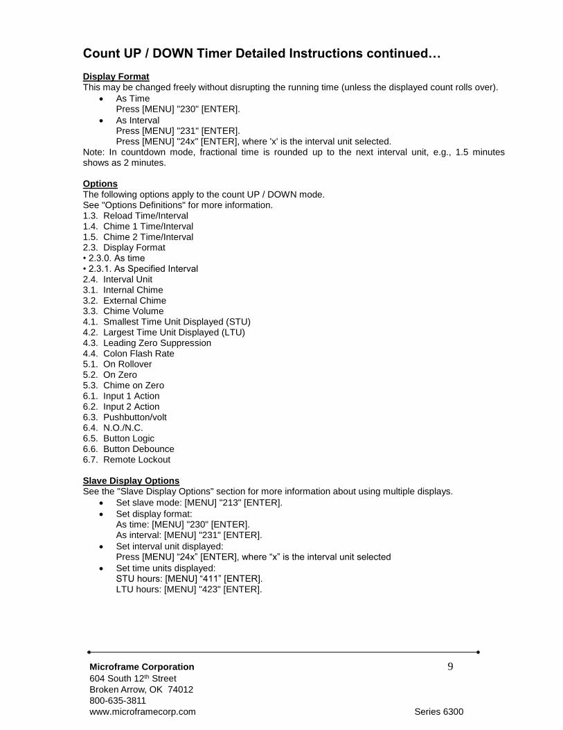
Count UP / DOWN Timer Detailed Instructions continued… Display Format This may be changed freely without disrupting the running time (unless the displayed count rolls over).
As Time Press [MENU] "230" [ENTER].
As Interval Press [MENU] "231" [ENTER]. Press [MENU] "24x" [ENTER], where 'x' is the interval unit selected.
Note: In countdown mode, fractional time is rounded up to the next interval unit, e.g., 1.5 minutes shows as 2 minutes. Options The following options apply to the count UP / DOWN mode. See "Options Definitions" for more information. 1.3. Reload Time/Interval 1.4. Chime 1 Time/Interval 1.5. Chime 2 Time/Interval 2.3. Display Format • 2.3.0. As time • 2.3.1. As Specified Interval 2.4. Interval Unit 3.1. Internal Chime 3.2. External Chime 3.3. Chime Volume 4.1. Smallest Time Unit Displayed (STU) 4.2. Largest Time Unit Displayed (LTU) 4.3. Leading Zero Suppression 4.4. Colon Flash Rate 5.1. On Rollover 5.2. On Zero 5.3. Chime on Zero 6.1. Input 1 Action 6.2. Input 2 Action 6.3. Pushbutton/volt 6.4. N.O./N.C. 6.5. Button Logic 6.6. Button Debounce 6.7. Remote Lockout Slave Display Options See the "Slave Display Options" section for more information about using multiple displays.
Set slave mode: [MENU] "213" [ENTER].
Set display format: As time: [MENU] "230" [ENTER]. As interval: [MENU] "231" [ENTER].
Set interval unit displayed: Press [MENU] “24x” [ENTER], where “x” is the interval unit selected
Set time units displayed: STU hours: [MENU] “411” [ENTER]. LTU hours: [MENU] "423" [ENTER].

Microframe Corporation 10
604 South 12th Street
Broken Arrow, OK 74012
800-635-3811
www.microframecorp.com Series 6300
Set Display to Counter Mode Using the remote control, press [MENU] "167" [ENTER]. The display is now in counter mode. Operation To control the counter with the remote control: [Up] button to increment the count by one [Down] button to decrement the count by one [Clear] button to reset the count to '0' To control the timer with the push buttons, you must first change the default function of the push buttons. See options 6.1 and 6.2 in the Options Definitions. [Input 1] to increment the count by one [Input 2] to decrement the count by one Set a New Count Using the remote control, type in the new number and press [ENTER]. Fast Inputs For events faster than 10 items per second, use Option 6.6.1. Options The following options apply to the counter mode. See "Options Definitions" for more information. 2.3. Display Format • 2.3.3. As count 6.1. Input 1 Action • 6.1.1 Up • 6.1.2 Down • 6.1.4 Reset 6.2. Input 2 Action • 6.2.1 Up • 6.2.2 Down • 6.2.4 Reset 6.3. Pushbutton/volt 6.4. Normally open/Normally closed 6.5. Button Logic 6.6. Button Debounce 6.7. Remote Lockout Slave Display Options See the "Slave Display Options" section for more information about using multiple displays.
Set slave mode: [MENU] "213" [ENTER].
Set display format as count: [MENU] “233” [ENTER].
Counter Detailed Instructions Counter Mode counts number of units.

Microframe Corporation 11
604 South 12th Street
Broken Arrow, OK 74012
800-635-3811
www.microframecorp.com Series 6300
Set Display to Takt Time Mode Using the remote control, press [MENU] "168" [ENTER]. The display is now in Takt time mode and defaults to an interval of 15 seconds. Set Takt Interval Press [MENU] “13” [ENTER]. Type in the Takt time interval in an “HH:MM:SS” format. For 10 seconds, type “10” [ENTER]. For 2 hours, type “20000” [ENTER]. Operation To control the timer with the remote control: [Up] button is not applicable. [Down] button to Start / Stop Takt time [Clear] button to reset the internal timer and zero the Takt count To control the timer with the push buttons, you must first change the default function of the push buttons. See options 6.1 and 6.2 in the Options Definitions. [Input 1] to Start / Stop Takt time [Input 2] to reset the internal timer and zero the Takt count Setting a New Takt Count Using the remote control, type in the new value and press [ENTER]. If the display is running, it will continue to increment. Changing the Takt Interval The Takt interval may be changed as previously noted. The last Takt interval may need to complete before the new interval is loaded. To apply the new interval immediately, reset the Takt timer. Battery Backup During a power outage, the current Takt number will be preserved. The Takt timer will not continue to run except that it will complete the current Takt interval. Thus the Takt time will only be behind if a Takt interval occurs while the unit is powered off. Options The following options apply to the Takt timer mode. See "Options Definitions" for more information. 1.3. Takt Interval (Reload Time) 6.3. Pushbutton/volt 2.3. Display Format 6.4. N.O./N.C. • 2.3.3. As count 6.5. Button Logic 6.1. Input 1 Action 6.6. Button Debounce 6.2. Input 2 Action 6.7. Remote Lockout Slave Display Options See the "Slave Display Options" section for more information about using multiple displays.
Set slave mode: [MENU] "213" [ENTER].
Set display format as count: [MENU] “233” [ENTER].
Takt Time Detailed Instructions Takt Time Mode increments a running units count at a specific time interval. It is normally used on production lines to set a target pace.

Microframe Corporation 12
604 South 12th Street
Broken Arrow, OK 74012
800-635-3811
www.microframecorp.com Series 6300
Set Display to Slave Mode Using the remote control, press [MENU] "213" [ENTER]. The display is now in slave mode. Overview The 6300 Series displays allow multiple displays to work together. The primary display is referred to as the "master" display. Other displays controlled by the master are referred to as "slave" displays. All of the operating modes for the 6300 Series support slave displays. Slave displays get their information from the master via 485 communications (Terminals A, B, COMM). Connect slave displays to the master with 3 or 5-conductor wire. The 5-conductor wire allows three wires for communications and two wires for power to slave displays. Five-conductor wire is suitable for short power runs. For longer runs, power the slave displays separately. Power runs to multiple displays are limited by the distance required and the number of displays powered. Communication runs can be up to 3000 ft. long. While slaves show the same information as the master, they can reformat the data to appear differently than the master. For instance, for a count-up timer, three 4-digit dis- plays could be used to display everything from days down to hundredths of seconds: {0123} days, {21:53} hours/minutes, {47.89} seconds/hundredth of a second. Options The following options apply to the slave mode. See "Options Definitions" for more information. 2.3. Display Format • 2.3.0. As time • 2.3.1. As specified interval • 2.3.2. As date • 2.3.3. As count (for unit counter and takt timer modes) 2.4. Interval Unit (if 2.3.1 set) 3.1. Internal Chime 3.2. External Chime 3.3. Chime Volume 4.1. Smallest Time Unit Displayed (STU) (for 2.3.0 or 2.3.1) 4.2. Largest Time Unit Displayed (LTU) (for 2.3.0 or 2.3.1) 4.3. Leading Zero Suppression 4.4. Colon Flash Rate 6.7. Remote Lockout See the Appendix for a Slave Wiring diagram.
Slave Display Options

Microframe Corporation 13
604 South 12th Street
Broken Arrow, OK 74012
800-635-3811
www.microframecorp.com Series 6300
Overview The 6300 Series Display has been designed to allow the user to control almost every aspect of the display’s behavior. In order to change the behavior of the display you change the value of a specific parameter in the display's memory. Any changes made to the display's memory will be stored even when the display does not have power. A map of the configurable memory options is shown in the Options Table Summary on the following pages. A detailed description of each value can be found in the Options Definitions section. The display’s memory map has been broken into six main sections and their subsections. Section 1 Subsections 1.1 through 1.5 store multiple number values representing the following: Current Time, Current Date, Reload Time, Chime Time 1, and Chime Time 2.
To change values in these areas simply press [MENU] followed by the area number, e.g., [Menu] "12" to change the date, followed by [ENTER]. Next, type in up to six digits of the value representing the time or date followed by [ENTER], e.g., if setting time to 3:00, type “300” [ENTER].
Subsection 1.6 is a special “Quick Set section.” It is actually not a memory area at all but a function that sets all other memory areas to a factory “Default” condition.
For instance if you want to set all memory areas to what Microframe considers normal for a wall clock, type [MENU] "160" [ENTER]. This will reset all of the necessary memory locations (sections 2 through 6) to “Default” settings for a given mode.
Sections 2 - 6 Sections 2 through 6 are straightforward, single-number memory locations. For instance, area 2.1 can have a value of 0 to 5, whereas area 2.2 can have a value of 0 to 1. See the Options Table Summary for allowable values for each area. Use these areas to alter the details of how the display behaves.
Examples of Changing Values in Areas 2 - 6 To make the internal chime volume louder, increase the value in area 3.3. Press [MENU], “339” (for highest volume) [ENTER].
To make the display chime momentarily when it reaches zero in countdown mode, change area 5.3 to a value of 1. Press [MENU] "531" [ENTER].
Setting the Programmable Options This will tell the display how to behave.
Microframe Corporation 14
604 South 12th Street
Broken Arrow, OK 74012
800-635-3811
www.microframecorp.com Series 6300
2 Behavior 2.1 Operation 2.1.0 Wall Clock 2.1.1 Count Up 2.1.2 Countdown 2.1.3 Slave Display 2.1.4 Unit Counter 2.1.5 Takt Time 2.2 Clock Format 2.2.0 12 hr 2.2.1 24 hr 2.3 Display Format 2.3.0 As time 2.3.1 As interval (see 2.4) 2.3.2 As date 2.3.3 As count (for 2.1.4 and 2.1.5) 2.4 Interval Unit 2.4.0 Hundredths of a second 2.4.1 Seconds 2.4.2 Minutes 2.4.3 Hours 2.4.4 Days
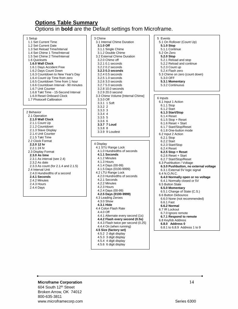
Options Table Summary Options in bold are the Default settings from Microframe.
1 Setup 1.1 Set Current Time 1.2 Set Current Date 1.3 Set Reload Time/Interval 1.4 Set Chime 1 Time/Interval 1.5 Set Chime 2 Time/Interval 1.6 Quicksets 1.6.0 Wall Clock 1.6.1 Days Accident Free 1.6.2 Days Count Down 1.6.3 Countdown to New Year's Day 1.6.4 Count Up Time from zero 1.6.5 Countdown Time from 1 hour 1.6.6 Countdown Interval - 90 minutes 1.6.7 Unit Counter 1.6.8 Takt Time - 15-Second Interval 1.6.9 Reset Onboard Clock 1.7 Photocell Calibration
3 Chime 3.1 Internal Chime Duration 3.1.0 Off 3.1.1 Single Chime 3.1.2 Double Chime 3.2 External Chime Duration 3.2.0 Chime off 3.2.1 0.1 seconds 3.2.2 0.2 seconds 3.2.3 0.3 seconds 3.2.4 0.5 seconds 3.2.5 1.0 seconds 3.2.6 3.0 seconds 3.2.7 5.0 seconds 3.2.8 10.0 seconds 3.2.9 20.0 second 3.3 Chime Volume [Internal Chime] 3.3.0 Off 3.3.1 1 Soft 3.3.2 2 3.3.3 3 3.3.4 4 3.3.5 5 3.3.6 6 3.3.7 7 Loud 3.3.8 8 3.3.9 9 Loudest
4 Display 4.1 STU Range Lock 4.1.0 Hundredths of seconds 4.1.1 Seconds 4.1.2 Minutes 4.1.3 Hours 4.1.4 Days (00-99) 4.1.5 Days (0100-9999) 4.2 LTU Range Lock 4.2.0 Hundredths of seconds 4.2.1 Seconds 4.2.2 Minutes 4.2.3 Hours 4.2.4 Days (00-99) 4.2.5 Days (0100-9999) 4.3 Leading Zeroes 4.3.0 Show 4.3.1 Hide 4.4 Colon Flash Rate 4.4.0 Off 4.4.1 Alternate every second (1s) 4.4.2 Flash every second (0.5s) 4.4.3 Flash twice per second (0.25) 4.4.4 On (when running) 4.5 Size (factory set) 4.5.2 2 digit display 4.5.3 3 digit display 4.5.4 4 digit display 4.5.6 6 digit display
5 Events 5.1 On Rollover (Count Up) 5.1.0 Stop 5.1.1 Continue 5.2 On Zero 5.2.0 Stop 5.2.1 Reload and stop 5.2.2 Reload and continue 5.2.3 Count up 5.2.4 Flash zero 5.3 Chime on zero (count down) 5.3.0 OFF 5.3.1 Momentary 5.3.2 Continuous
6 Inputs 6.1 Input 1 Action 6.1.1 Stop 6.1.2 Start 6.1.3 Start/Stop 6.1.4 Reset 6.1.5 Stop + Reset 6.1.6 Reset + Start 6.1.7 Start/Stop/Reset 6.1.8 One-button mode 6.2 Input 2 Action 6.2.1 Stop 6.2.2 Start 6.2.3 Start/Stop 6.2.4 Reset 6.2.5 Stop + Reset 6.2.6 Reset + Start 6.2.7 Start/Stop/Reset 6.3 Pushbutton / Voltage 6.3.0 Pushbutton, no external voltage 6.3.1 External 5V logic signal 6.4 N.O./N.C. 6.4.0 Normally open or no voltage 6.4.1 Normally closed or 5V 6.5 Button State 6.5.0 Momentary 6.5.1 Change of State (C.S.) 6.6 Button Debounce 6.6.0 None (not recommended) 6.6.1 Fast 6.6.2 Normal 6.7 IR Lockout 6.7.0 Ignore remote 6.7.1 Respond to remote 6.8 Keyfob Address 6.8.0 Address 0 6.8.1 to 6.8.9 Address 1 to 9

Microframe Corporation 15
604 South 12th Street
Broken Arrow, OK 74012
800-635-3811
www.microframecorp.com Series 6300
Setup 1.1 Set Current Time
Sets the internal clock's time. Since this display does not have AM/PM indicators, time must be entered in military format, e.g., 3 p.m. = 15:00.
Prompt Wall Clock (2.1.0) HH:MM [ENTER] -or- HH:MM:SS [ENTER] Any other (2.1.x) HH:MM:SS [ENTER] HH=hours, MM=minutes, SS=seconds
1.2 Set Current Date
Sets the internal clock's date.
Prompt MM / DD / YY MM=month, DD=day, YY=year
The RTC and firmware in this product will operate in the year range 2000-2099 (01/01/00-12/31/99). 1.3 Set Reload Time / Interval
Sets the countdown timer's reload time or interval. Any time the countdown timer is reset, it will go back to this value.
Prompt Time format (2.3.0) HH:MM:SS [ENTER], DDDD [ENTER] Interval format (2.3.1) NNNNNN [ENTER] HH=hours, MM=minutes, SS=seconds, DDDD=days N=quantity of the set interval unit This option also serves as the Takt time interval.
Prompt TAKT time (2.1.5) HH:MM:SS [ENTER], DDDD [ENTER] HH=hours, MM=minutes, SS=seconds, DDDD=days If you wish to set hundredths of seconds for the reload time, first change the display mode to interval (2.3.1) and the interval unit to hundredths of seconds (2.4.0).
1.4 Set Chime 1 Time / Interval
Sets a specific chime time/interval for wall clock and timer modes. When the current time/interval matches this value, the internal and external chimes will be activated (if enabled).
Prompt Time format (2.3.0) HH:MM:SS [ENTER], DDDD [ENTER] Interval format (2.3.1) NNNNNN [ENTER] HH=hours, MM=minutes, SS=seconds, DDDD=days N=quantity of the set interval unit
1.5 Set Chime 2 Time / Interval
A second chime time/interval. Entry is the same as 1.4.
Options Definitions Helpful information about all of the choices shown in the Options Table Summary.

Microframe Corporation 16
604 South 12th Street
Broken Arrow, OK 74012
800-635-3811
www.microframecorp.com Series 6300
Options Definitions continued… Setup continued… 1.6 Quicksets
These allow quick access to commonly used settings. For proper operation, options 1.6.1, 1.6.2, and 1.6.3 require the date and time to be set before selecting them.
1.6.0 Wall Clock Shows the current time of day Sets all other options needed to make sure time is displayed as expected: HH:MM:SS or HH:MM.
1.6.1 Days Accident Free - Count Up Counts up the days that have been accident-free. First, set the date and time. Next, select this option. You will be prompted for the current day, press [ENTER]. The day count will advance at midnight automatically.
1.6.2 Days Countdown Counts down by days. First, set the date and time. Next, select this option. You will be prompted for the current day, press [ENTER]. The day count will decrement at midnight automatically.
1.6.3 Countdown Time to New Year's Day Counts down the time until New Year's Day. First, set the date and time. Important: Do not use daylight savings when setting the time or the count
will be off by 1 hour. Next, select this option. The display will begin counting down the time remaining until the New Year in the format "DDDD.HH: MM:SS". Note that slave displays can be used to show the portion of the time that does not fit on the master display.
1.6.4 Count Up Time from 0:00 Sets up a timer to start counting up from zero.
1.6.5 Countdown Time 1 hour Sets up a timer to start counting down from 1 hour.
1.6.6 Countdown Interval 90 minutes Sets up a timer to countdown 90 by minute intervals.
1.6.7 Unit Counter Sets up a unit counter so that input pulses can be counted from Input 1 or Input 2.
1.6.8 Takt Timer - 15-second interval Sets up a Takt timer such that every 15 seconds the display will increment by 1 unit. Press the [DOWN] button to start the timer.
1.6.9 Reset Onboard Clock The internal RTC can be reset. Resets the date and time. Note: This will probably impact the current display's operation.
1.7 Photocell calibration
Allows the user to adjust the photocell offset, so that side-by-side displays are the same brightness. Calibration steps:
Select an indoor room with lighting of average brightness. The calibration does not work well in a dark room or in full sunlight.
Plug in displays side-by-side.
Enter this option (Menu 17 Enter). The raw photocell reading is displayed. Subtract the lower number from the higher one. This will be our offset. Write this down.
Unplug the display(s) that will not be changed.
Press [ENTER] to continue, or [EXIT] to quit. The current offset is displayed (default 40). Add the offset to the number displayed, type it in with the remote, and press [ENTER]. e.g. if you wrote down "12" in the last step, you will type in "52" [ENTER].
Display brightness should now match. If not, repeat steps above, using a different offset.
Microframe Corporation 17
604 South 12th Street
Broken Arrow, OK 74012
800-635-3811
www.microframecorp.com Series 6300
Operations Definitions continued…
Behavior 2.1 Operation
Determines the fundamental behavior of the display.
2.1.0 Wall Clock Shows the current time or date
2.1.1 Count Up Counts up by time or interval
2.1.2 Countdown Counts down by time or interval
2.1.3 Slave Display Shows information from a master display
2.1.4 Unit Counter Counts parts or events
2.1.5 Takt Timer Keeps track of Takt time
2.2 Clock Format
Allows the clock to show time in standard 12-hour format or in 24-hour military time. 2.3 Display Format
Determines how the unit displays information to the user. This may be changed freely without disrupting the running time (see caution below about interval units.) Display formats do not apply to all modes. Slave displays will only show the date if the master is also showing the date.
2.3.0 As time Show in standard time format DDDD.HH:MM:SS.hh (hundredths of a second) Max: 9999.23:59:59.99 Applies to: 2.1.0, 2.1.1, 2.1.2, 2.1.3
2.3.1 As specified interval Show by the interval specified in 2.4 Max: 65535 days, 999999 all other units Applies to: 2.1.1, 2.1.2, 2.1.3
2.3.2 As date Show the date Applies to: 2.1.0, 2.1.3
2.3.3 As count Show the current unit count Applies to: 2.1.3, 2.1.4, 2.1.5
2.4 Interval Unit
Determines by what unit the time is displayed. Option 2.3.1 must be set for this option to take effect. Caution: Changing to a smaller interval unit, such that the resulting number is too large to display, will cause a
display overflow. If the display is stopped or counting down, you will see bars across the top of the screen. If the display is counting up, the On Rollover event will be triggered. Triggering this event modifies your time! With this in mind, you are free to change this setting even while the display is running. For safety, set this option to days before changing the display format to interval.

Microframe Corporation 18
604 South 12th Street
Broken Arrow, OK 74012
800-635-3811
www.microframecorp.com Series 6300
Options Definitions continued…
Chime Both the internal and external chime activate at the same time. 3.1 Internal Chime Duration
Sets whether the internal chime sounds: none, once, or twice. The display comes standard with the internal chime. 3.2 External Chime Duration
Sets the duration of the external chime. This is actually an external "chime driver" circuit that may be purchased at the time of order. For AC loads (such as a doorbell), the triac option is recommended. For DC loads, the relay option is recommended. 3.3 Chime Volume [Internal Chime]
Sets the volume of the internal chime.
Display 4.1 STU Range Lock
Sets the smallest time unit that will be shown by the display, e.g., to have a 4-digit display show hours and minutes (never seconds), set this value to "2." 4.2 LTU Range Lock
Sets the largest time unit that will be shown by the display, e.g., to have a 4-digit display show hours and minutes (never seconds), set this value to "3." 4.3 Leading Zeros
Shows or hides the leading zeros for timers. Unit Counter and Takt time modes always suppress the leading zeroes. 4.4 Colon Flash Rate
Determines how fast the colons flash while the timer is running. 4.5 Size
This is the display's factory set number of digits. A four-digit display is indicated by a "4." This option lets the display know how much information it can show on the screen. Note: Some input prompts can only display all of the information on a 6-digit display. Smaller displays will show only the right hand portion of the prompt.
Events 5.1 On Rollover
Determines what to do when the count up time / interval (2.1.1) overflows. Time rollover point occurs when the LTU (4.2) time unit overflows. Interval rollover occurs at 65535 Days, 999999 Hours, Minutes, Seconds, Hundredths of a Second.
5.1.0 Stop Displays the last valid time or interval before the rollover.
5.1.1 Continue Resets to zero and continues counting up.
5.2 On Zero
Determines what to do when the count down time / interval (2.1.2) reaches zero.
5.2.0 Stop Stays at zero
5.2.1 Reload & Stop Load the default countdown time

Microframe Corporation 19
604 South 12th Street
Broken Arrow, OK 74012
800-635-3811
www.microframecorp.com Series 6300
Options Definitions continued… Events continued…
5.2.2 Reload & Continue Load the default countdown time and continue counting down
5.2.3 Count Up Start counting up from zero
5.2.4 Flash Zero Flashes zero until a button is pressed
Inputs 6.1 Input 1 Action
Determines what action occurs when Input 1 is activated.
6.1.1 Stop Stops Timer
6.1.2 Start Starts Timer
6.1.3 Start/Stop Alternately starts and stops timer
6.1.4 Reset Resets timer
6.1.5 Stop & Reset Stops Timer and Resets it
6.1.6 Reset & Start Resets Timer and Starts it
6.1.7 Start/Stop/Reset Alternately starts and stops timer, resetting each time
6.1.8 One-Button Mode 1st press starts timer, 2nd press stops timer, 3rd press performs Input 2 Action
6.2 Input 2 Action
Determines what action occurs when Input 2 is activated.
6.2.1 Stop Stops Timer
6.2.2 Start Starts Timer
6.2.3 Start/Stop Alternately starts and stops timer
6.2.4 Reset Resets timer
6.2.5 Stop & Reset Stops Timer and Resets it
6.2.6 Reset & Start Resets Timer and Starts it

Microframe Corporation 20
604 South 12th Street
Broken Arrow, OK 74012
800-635-3811
www.microframecorp.com Series 6300
Options Definitions continued… Inputs continued…
6.2.7 Start/Stop/Reset Alternately starts and stops timer, resetting each time
6.3 Pushbutton/Voltage
Sets whether the display should source 5V to monitor buttons, or if it should accept 5V (TTL level) from an external input.
6.3.0 Push buttons
6.3.1 Voltage A 5V signal may be applied. Caution: Ensure the grounds between the display and the sending device are properly tied together. DO NOT EXCEED 5.5V.
6.4 N.O. / N.C.
Defines the default state of the inputs: Normally Open or Normally Closed
6.4.0 Normally open. Contact: doorbell Voltage: 0V
6.4.1 Normally closed. Contact: N.C. relay Voltage: V.5
6.5 Button State
6.5.0 Momentary Expects a momentary contact closure at Inputs 1 and 2. For example: a doorbell button. Responds any time the input changes from open to closed.
6.5.1 Change of State Expects a toggling closure at Inputs 1 and 2. For example: an on/off switch. Responds any time the input changes from open to closed or closed to open.
6.6 Button Debounce
Ignores noise on Inputs 1 & 2. During a single press, buttons can "bounce" many times. This results in additional button presses that the user did not intend. This option ignores the additional button bouncing.
6.6.0 None No debouncing. Provides an instant response to any input. Not recommended for push buttons.
6.6.1 Fast Triggers on the leading edge of input; has a small delay between inputs. This is useful where the input is a high speed, low noise signal (some micro-switches and PLCs.)
6.6.2. Normal Waits for input signal to stabilize before acting on it.
6.7 IR Lockout
Sets whether the display ignores or responds to the remote. Toggle IR lockout on/off by pressing and holding [EXIT] on the remote for 5 seconds. The display will indicate the change by showing "ir0" or "ir1," where "0" = locked and "1" = normal. 6.8 Keyfob Address
This option is for our wireless displays. This adds the ability to set a keyfob address. This allows for independent keyfob/display systems to be used side-by-side. Note: pressing two keyfobs at the same time will still cause interference, because all keyfobs operate on the same frequency.

Microframe Corporation 21
604 South 12th Street
Broken Arrow, OK 74012
800-635-3811
www.microframecorp.com Series 6300
SERIES 6300
Appendix to INSTALLATION & SPECIFICATION GUIDE

Microframe Corporation 22
604 South 12th Street
Broken Arrow, OK 74012
800-635-3811
www.microframecorp.com Series 6300
Wiring Diagram
Slave Display Options

Microframe Corporation 23
604 South 12th Street
Broken Arrow, OK 74012
800-635-3811
www.microframecorp.com Series 6300
SYMPTOM
POSSIBLE CAUSE
CURE
Display will not light up. Display is not connected to
power or power adapter is
bad.
Check AC wall connection or change
to another wall outlet.
Display lights up but will not
respond to wired buttons.
Poor or no signal connection
to buttons.
Programming set to slave
mode.
Check signal cable connections to
buttons and check for proper wiring
on back panel. Try with a short cable
to prove whether the problem is in the
units or in the cable.
Buttons have no function in slave
mode. Change modes.
One or more segments do
not light up.
One or more LEDs burned out.
This typically happens only
when lightning strikes.
Call Microframe to receive an RMA and
then return to factory for repair.
Different displays are
showing different numbers
or times.
Poor signal connection to
master display or displays are
in different modes.
Check signal cables and routing.
Make sure 'A' and 'B' wires are not
reversed. Check Programmable
Options to make sure correct modes
are selected.
Display is not showing
expected time, despite
correct options.
Display size incorrect Check area 4.5 and set to correct
display size if necessary.
Timer/Clock Troubleshooting Chart
Colons do not flash or they
stay on.
Programming set to disable
colons or flash rate. Display is
not getting enough power.
Check the programming and change
as necessary.
Remote Control Troubleshooting
Remote control buttons
stopped responding.
Remote Locked Up
Batteries dead
Remove Batteries. Press [Menu] 3
times. Insert batteries and check for
operation.
Replace batteries.
General Troubleshooting Chart

Microframe Corporation 24
604 South 12th Street
Broken Arrow, OK 74012
800-635-3811
www.microframecorp.com Series 6300
Features The 6300 Series display is a 2, 3, 4, or 6-digit intelligent LED display with infrared capabilities. This display has
two inputs for buttons or logic controls and a communica-
tions link for communicating with other displays. Displays
are powered by a 24-Volt AC adapter (included). Displays include a built-in audio chime and remote control.
Broad Time Range: 0.01 seconds to 9999 days.
Backup Battery This product contains a high capacity lithium backup battery. The battery is designed to last a minimum of 10 years at temperatures up to 40°C (140°F).
Model 6300 Specifications
Voltage Input Requirements…………………… 24 volts AC or DC
Character Height………………………………… 5.5 inches
Character Viewing Distance……………………. 125 feet
Temperature Parameters………………………. 0ºC to 40ºC (32ºF to 140ºF)
Casing……………………………………………. Aluminum xtrusion
Color………………………………………………. Black frame with dark red acrylic faceplate
Environment……………………………………… Indoor use
Display Size 2-Digit 3-Digit 4-Digit 6-Digit
Power Requirements 2.9 watts 3.5 watts 4.6 watts 6.8 watts
Weight 2.5 lbs 3.2 lbs 3.9 lbs 5.25 lbs
Width "A" Dimension Inches 9.8" 13.2" 16.8" 24"
Width "A" Dimension Centimeters 24.9 cm 33.5 cm 42.7 cm 61.4 cm
Model 6300 Specifications Stand-Alone Displays

Microframe Corporation 25
604 South 12th Street
Broken Arrow, OK 74012
800-635-3811
www.microframecorp.com Series 6300
Model 6300 Specifications
Voltage Input Requirements…………………… 24 volts AC or DC
Character Height………………………………… 5.5 inches
Character Viewing Distance……………………. 125 feet Temperature Parameters………………………. Keyfob Range……………………………………. Keyfob Frequency……………………………….
0ºC to 40ºC (32ºF to 140ºF) 60 to 75 ft 418 Mhz
Casing……………………………………………. Aluminum extrusion
Color………………………………………………. Black frame with dark red acrylic faceplate
Environment……………………………………… Indoor use
Display Size 2-Digit 3-Digit 4-Digit 6-Digit
Power Requirements 2.9 watts 3.5 watts 4.6 watts 6.8 watts
Weight 2.5 lbs 3.2 lbs 3.9 lbs 5.25 lbs
Width "A" Dimension Inches 9.8" 13.2" 16.8" 24"
Width "A" Dimension Centimeters 24.9 cm 33.5 cm 42.7 cm 61.4 cm
Model 6300 Specifications Stand-Alone Wireless Displays
Features Wireless 6300 displays function identically to our D6300 displays. Just secure the provided antenna to the top of the display and use the wireless keyfob to control the display from a distance. Keyfobs can be custom ordered with addresses from 0-9 to allow for separate display/keyfob pairs. Each display includes a built-in audio chime.

Microframe Corporation 26
604 South 12th Street
Broken Arrow, OK 74012
800-635-3811
www.microframecorp.com Series 6300
Model 6300XXX8 Specifications
Voltage Input Requirements…………………… 24 volts AC or DC
Character Height………………………………… 8 inches
Character Viewing Distance……………………. 250 feet
Temperature Parameters………………………. 0ºC to 40ºC (32ºF to 140ºF)
Casing……………………………………………. Aluminum extrusion
Color………………………………………………. Black frame with dark red acrylic faceplate
Environment……………………………………… Indoor use
Display Size 2-Digit 3-Digit 4-Digit 6-Digit
Power Requirements 4.8 watts 6.5 watts 8.3 watts 12.0 watts
Weight 3.4 lbs 4.7 lbs 6.0 lbs 8.1 lbs
Width "A" Dimension Inches 11.5" 16.4" 21.3" 31.1"
Width "A" Dimension Centimeters 29.2 cm 41.7 cm 54.1 cm 79.0 cm
Model 6300XXX8
Specifications
Features The 6300XXX8 series is a larger version (8”) of our timer display. Box contents: (1) Display (1) 24VAC adapter w/ 20ft Wire (1) Screwdriver (1) IR Remote Control (2) Brass Push Buttons (1) Bundle 40ft wire for buttons
Backup Battery This product contains a high capacity lithium backup battery. The battery is designed to last a minimum of 10 years at temperatures up to 40°C (140°F).

Microframe Corporation 27
604 South 12th Street
Broken Arrow, OK 74012
800-635-3811
www.microframecorp.com Series 6300
Model 6300XXX8 Specifications
Voltage Input Requirements……………… 24 volts AC or DC
Character Height…………………………… 8 inches
Character Viewing Distance………………. 250 feet
Temperature Parameters…………………. 0ºC to 40ºC (32ºF to 140ºF)
Keyfob Range………………………………. 60 to 75 ft
Keyfob Frequency…………………………. 418 Mhz
Casing………………………………………. Aluminum extrusion
Color…………………………………………. Black frame with dark red acrylic faceplate
Environment………………………………… Indoor use
Display Size 2-Digit 3-Digit 4-Digit 6-Digit
Power Requirements 4.9 watts 6.6 watts 8.4 watts 12.1 watts
Weight 3.0 lbs 4.3 lbs 5.6 lbs 7.7 lbs
Width "A" Dimension Inches 11.5" 16.4" 21.3" 31.1"
Width "A" Dimension Centimeters 29.2 cm 41.7 cm 54.1 cm 79.0 cm
Model 6300XXXW
Specifications
Features The 6300XXXW series is an 8” keyfob controlled version of our timer display. Box contents: (1) Display (1) 24VAC adapter w/ 20ft Wire (1) Screwdriver (1) IR Remote Control (1) RF Keyfob
Backup Battery This product contains a high capacity lithium backup battery. The battery is designed to last a minimum of 10 years at temperatures up to 40°C (140°F).