senstar sennet & starcom rtu guide - ossi - …€¦ · _____ senstar sennet / starcom rtu...
TRANSCRIPT

Senstar Sennet &
Starcom RTU Guide
Version 3.x

_______________________ Senstar Sennet / Starcom RTU Guide Ver 3.x ______________________
Copyright © 1999- 2012 OSSI, LLC. 2
OSSI W228 N727 Westmound Dr Waukesha WI 53186 USA
TEL: 262-522-1870
FAX: 262-522-1872 Ossi-usa.com
Intelli-Site Security Management Software
Senstar Sennet & Starcom RTU
Guide
PC Software RTU Interface Guide
For Windows 7 SP1, 2008 R2 SP1, XP SP3 & 2003 SP2
Version 3.x
Copyright © 1999 – 2012 OSSI, LLC.

_______________________ Senstar Sennet / Starcom RTU Guide Ver 3.x ______________________
Copyright © 1999- 2012 OSSI, LLC. 3
Copyright Copyright © 1999-2012 OSSI, LLC. All rights reserved.
Information in this document is subject to change without notice. The software described
in this document is furnished under a license agreement or nondisclosure agreement. The
software may be used or copied only in
accordance with the terms of those agreements. No part of this publication may
be reproduced, stored in a retrieval system, or transmitted in any form or any means
electronic or mechanical, including photocopying and recording for any purpose
other than the purchaser’s use without the written permission of OSSI
OSSI
W228 N727 Westmound Dr Waukesha WI 53186
TEL: 262-522-1870 FAX: 262-522-1872
Trademarks Intelli-Site® is a registered trademark of OSSI LLC. Intelli-Site®
is registered in U.S. Patent
& Trademark Office.
All other registered and unregistered
trademarks are the sole property of their respective owners.

_______________________ Senstar Sennet / Starcom RTU Guide Ver 3.x ______________________
Copyright © 1999- 2012 OSSI, LLC. 4
Table of Contents Copyright ................................................................................... 3
Trademarks .............................................................................. 3
Table of Contents ................................................................. 3
Section 1 – Introduction .................................................. 5
Overview ...................................................................................... 5
Technical Support Assistance .............................................. 6
OSSI Headquarters ........... Error! Bookmark not defined.
Technical Support ............. Error! Bookmark not defined.
Section 2 – Sennet RTU Configuration .................... 7
Adding a Sennet RTU to the Intelli-Site Tree ................ 7
Add an RTU – Procedure ................................................. 7
Import an RTU – Procedure ........................................... 8
Sennet Configuration ............................................................ 10
RTU Node (Parent Node) ............................................... 10
Alarms ................................................................................... 12
Section 3 – Setting up an OmniTrax zone ........... 13
Section 4 – Starcom RTU Configuration ............... 19
Section 5 – Driver Setup and Configuration ...... 22

_______________________ Senstar Sennet / Starcom RTU Guide Ver 3.x ______________________
Copyright © 1999- 2012 OSSI, LLC. 5
Section 1 – Introduction
This section describes the following:
Overview
Technical Support Assistance
Overview
The Sennet and Starcom RTUs
(Receiver/Transmitter Unit) are the Intelli-Site software representations of a Sennet field
devices and Starcom protocols.
The Sennet and Starcom RTUs provide for user
configuration of all aspects of the field devices and Starcom protocol:
Sennet and Starcom general configuration
Input configuration
Output configuration Alarms configuration

_______________________ Senstar Sennet / Starcom RTU Guide Ver 3.x ______________________
Copyright © 1999- 2012 OSSI, LLC. 6
Technical Support Assistance
OSSI Headquarters W228 N727 Westmound Dr.
Waukesha WI 53186 USA
Tel: 262-522-1870 Fax: 262-522-1872
Technical Support
Technical support is available via Telephone, Fax or Email. Contact OSSI Technical Support
8:00 AM to 5:00 PM Central Standard time. If calling after hours, please leave a detailed
voice mail message, and someone will return your call as soon as possible.
E-Mail: [email protected]
Fax: 262-522-1872 (Attention Technical
Support) Local: 262-522-1870
When calling, please be at the computer prepared to provide the following information:
Product version number, found by selecting
the About button from the Intelli-Site
Menu Application Bar. Product serial number used for registration.
The type of computer being used including, operating system, processor type, speed,
amount of memory, type of display, etc. Exact wording of any messages that appear
on the screen. What was occurring when the problem was
detected? What steps have been taken to reproduce
the problem?

_______________________ Senstar Sennet / Starcom RTU Guide Ver 3.x ______________________
Copyright © 1999- 2012 OSSI, LLC. 7
Section 2 – Sennet RTU Configuration
This section describes the following Design Mode RTU activities in Intelli-Site.
Adding a Sennet RTU to the Intelli-Site tree
Sennet RTU Configuration
Adding a Sennet RTU to the Intelli-
Site Tree
The following section will describe how to add one or more Sennet RTU nodes to the tree. All
procedures described in this section are accomplished in Design Mode.
Add an RTU – Procedure
1. Expand the System Layout Node and Right-Click on an Area. Select Add
Node… from the Shortcut Menu as shown below:
Note: The total number of RTUs that may be added must not
exceed 255 for a given domain.

_______________________ Senstar Sennet / Starcom RTU Guide Ver 3.x ______________________
Copyright © 1999- 2012 OSSI, LLC. 8
2. The RTU(s) will be added to the tree and
the system level Text-To-Speech
message “Node Added” will sound.
Import an RTU – Procedure
1. Expand the System Layout Node and Right-Click on an Area. Select Add
Node… from the Shortcut Menu as shown below:

_______________________ Senstar Sennet / Starcom RTU Guide Ver 3.x ______________________
Copyright © 1999- 2012 OSSI, LLC. 9
2. Select the Browse button on the Add Node dialog: A browse window will
open. Browse to the appropriate location then select the RTU .exp file you wish to
import and select the Open button. A new type (Custom) will be automatically
added to the Add Node dialog and the imported .exp will be listed below the
Custom type.
3. Select the imported RTU then enter the
number of devices you wish to add to the tree in the Total number to add: edit
box. You may add multiple devices to an
area.

_______________________ Senstar Sennet / Starcom RTU Guide Ver 3.x ______________________
Copyright © 1999- 2012 OSSI, LLC. 10
4. The RTU(s) will be added to the tree and the system level Text-To-Speech
message “Node Added” will sound.
Sennet Configuration
The following section describes configuration of
the various elements of the Sennet RTUs.
The Sennet LTU RTU, for example, consists of
a parent (the basic Sennet node) and three children as follows:
Sensor Alarms – a collection of all sense inputs.
Controls – a collection of all control counters.
Alarms – the collection of all alarms.
RTU Node (Parent Node)
The parent (Sennet LTU) node is configured by
Right-Clicking on the RTU and selecting Properties...
RTU Setting Tab
_______________________ Senstar Sennet / Starcom RTU Guide Ver 3.x ______________________
Copyright © 1999- 2012 OSSI, LLC. 11
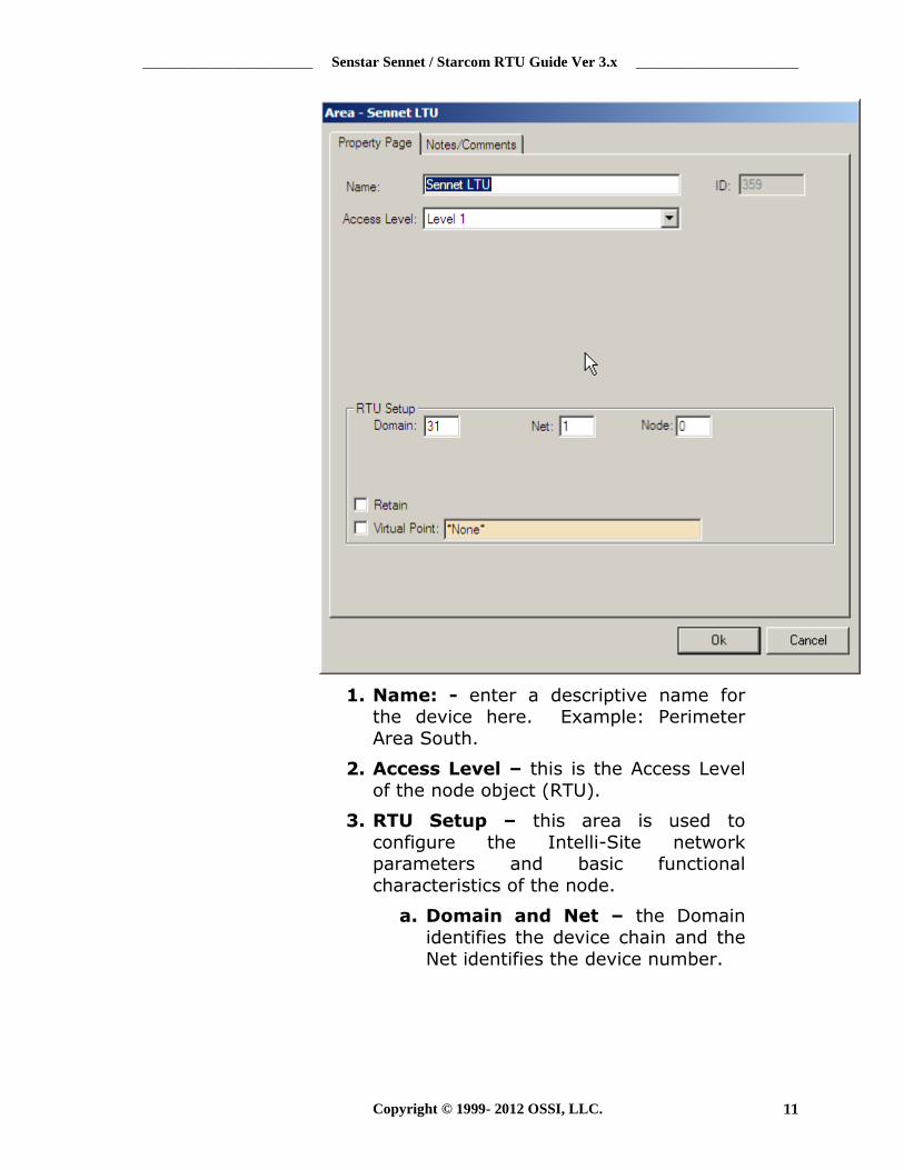
1. Name: - enter a descriptive name for the device here. Example: Perimeter
Area South.
2. Access Level – this is the Access Level
of the node object (RTU).
3. RTU Setup – this area is used to
configure the Intelli-Site network parameters and basic functional
characteristics of the node.
a. Domain and Net – the Domain
identifies the device chain and the
Net identifies the device number.

_______________________ Senstar Sennet / Starcom RTU Guide Ver 3.x ______________________
Copyright © 1999- 2012 OSSI, LLC. 12
Note: The Domain of an Ethernet-based (TCP/IP) panel will be unique for each panel. It is
recommended that the net (and panel number) for Ethernet panels
be set to 1.
b. Virtual Point – allows the user to
make the RTU a virtual RTU by specifying a V-Point from the
Virtual Points node.
Alarms
The Alarms subnode on the Sennet RTU contains premade alarm conditions that can
notify the operator of a specific problem with
the field device.
1. Panel Online: This point will be set on
when the Sennet driver is communicating with the Network Manager
2. Connected: This point will be set on when the Network Manager is
communicating with the Sennet field device
3. Side X Fault: This point will be set on when a Side X Fault is detected
4. Side Y Fault: This point will be set on when a Side Y Fault is detected
5. ROM Error: this point will be set on when a ROM error is detected
6. RAM Error: this point will be set on
when a RAM error is detected
7. Enclosure Tamper: this point will be set
on when and enclosure tamper is detected
Note: The RTU setup and configuration of Sennet variations is similar to the steps above. This
applies to: Crossfire, MX-Series, IPCC, and Silver. The subnodes
under each may vary, but the
setup is the same.

_______________________ Senstar Sennet / Starcom RTU Guide Ver 3.x ______________________
Copyright © 1999- 2012 OSSI, LLC. 13
Section 3 – Setting up an OmniTrax zone This section describes the procedure that will allow the project file programmer to create a functional Omnitrax alarm zone.
Add and Omnitrax RTU to the Project Tree: Expand the
System Layout section of the Project Tree and right-click on the Area Node under the Corporate Headquarters Site Node:
Select Add Node… from the popup dialogue and then select Silver Omnitrax from the Add Node dialogue:
Select the Add Node button to add the Omnitrax RTU to the Project Tree.
Step 2 – Add Virtual Points RTU to the Project Tree: Right-click on the Area node under the Corporate Headquarters node:

_______________________ Senstar Sennet / Starcom RTU Guide Ver 3.x ______________________
Copyright © 1999- 2012 OSSI, LLC. 14
Select Add Node… from the popup dialogue and then select
Virtual Outputs from the Add Node dialogue:
Select the Add Node button to add the Virtual Outputs RTU to the Project Tree.
Step 3 – Rename Virtual Points: Rename the first four (4) Virtual Points as follows:
Zone 1 Alarm
Zone 1 Access
Zone 1 Failure
Zone 1 Tamper
Step 4 – Create an Alarm Zone Group: Expand the Door Control node and Right-click on the Alarm Zone node. Click Add
Node… to create an Alarm Zone Group.
Step 5 – Create an Alarm Zone: Right-click on the Alarm Zone Group and select Add Node and Edit… to create an Alarm
Zone Construct:
Step 6 – Add Points to the Alarm Zone Construct: Add the
following points to the Alarm Zone Construct:
_______________________ Senstar Sennet / Starcom RTU Guide Ver 3.x ______________________
Copyright © 1999- 2012 OSSI, LLC. 15
Drag-and-drop the Silver Omnitrax Cable Zone 1 point into the Sensor Field under the Sensor List.
Drag-and-drop the Zone 1 Alarm virtual point into the Alarm Output point field.
Drag-and-drop the Zone 1 Access virtual point into the Access Input point field
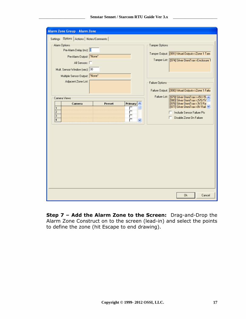
Drag-and-drop he Zone 1Tamper virtual point into the Tamper Output field (on the Options page)
Drag-and-drop the Zone 1 Failure virtual point into the Failure Output field (on the Options page)
Drag-and-drop the the Silver Omnitrax fault points into the Failure List (on the Options page)
Drag-and-drop the Silver Omnitrax Enclosure Tamper into the Tamper List (on the Options page)

_______________________ Senstar Sennet / Starcom RTU Guide Ver 3.x ______________________
Copyright © 1999- 2012 OSSI, LLC. 16
_______________________ Senstar Sennet / Starcom RTU Guide Ver 3.x ______________________
Copyright © 1999- 2012 OSSI, LLC. 17
Step 7 – Add the Alarm Zone to the Screen: Drag-and-Drop the
Alarm Zone Construct on to the screen (lead-in) and select the points to define the zone (hit Escape to end drawing).

_______________________ Senstar Sennet / Starcom RTU Guide Ver 3.x ______________________
Copyright © 1999- 2012 OSSI, LLC. 18
Step 8 – Specify the Starting and Ending Meter: As soon as the user hits the Escape key, the following dialog will appear. Enter the
Starting and Ending Meter in the appropriate boxes then click “OK”. The alarm zone will be filled in with the dropped one. The inactive
and active images will be filled it with ‘AlrLocn.ico’ and ‘AlrLocnActv.ico’

_______________________ Senstar Sennet / Starcom RTU Guide Ver 3.x ______________________
Copyright © 1999- 2012 OSSI, LLC. 19
Section 4 – Starcom RTU Configuration
This section describes the following Design Mode RTU activities in Intelli-Site.
Adding a Starcom Master RTU to the Intelli-
Site tree
Starcom Master RTU Configuration
Adding a Starcom Master RTU to the Intelli-
Site tree
Starcom Slave Configuration
Adding a Starcom Master RTU
The same process applies as previously
outlined in Section 2, except in the Add dialog, select “Starcom Master”
Starcom Master RTU configuration
Right-click on the “Starcom Master” RTU node, and select “Properties”
On the Starcom Master tab you will see two columns: Inputs and Outputs.

_______________________ Senstar Sennet / Starcom RTU Guide Ver 3.x ______________________
Copyright © 1999- 2012 OSSI, LLC. 20
o Inputs: reserved for points that the software uses to talk to a device.
o Outputs: reserved for points that the device uses to talk to the software.
Adding a Starcom Slave RTU
The same process applies as previously
outlined in Section 2, except in the Add dialog, select “Starcom Slave”
Starcom Slave RTU configuration
o Right-click on the “Starcom Slave” RTU, and select “Properties”
o As before, with the Sennet RTU, the setup is the same. The operator must fill
in the “Domain”, “Net” and “Node” appropriately, according to his project
configuration (i.e. number and placement of RTUs in the tree)
Starcom Slave RTU configuration
The subnodes underneath the “Starcom Slave” RTU parent node, are points that can be
assigned in the Starcom Master Input/Output grids.

_______________________ Senstar Sennet / Starcom RTU Guide Ver 3.x ______________________
Copyright © 1999- 2012 OSSI, LLC. 21

_______________________ Senstar Sennet / Starcom RTU Guide Ver 3.x ______________________
Copyright © 1999- 2012 OSSI, LLC. 22
Section 5 – Driver Setup and Configuration
This section describes how to set up the drivers in the Driver Service software for the Sennet and Starcom RTUs.
Adding a Sennet/Starcom driver to Driver
Service
Configuring the Sennet/Starcom driver
Adding and Configuring Sennet Driver
To add and configure a Sennet driver, open the Driver Service software, then click the “Add”
button, as shown below.

_______________________ Senstar Sennet / Starcom RTU Guide Ver 3.x ______________________
Copyright © 1999- 2012 OSSI, LLC. 23
Now, select the “Sennet” driver from the list, and click on “OK”
At this point the driver configuration tabs will appear, and in the first tab, “Server”, type in
the “Host Address” computer name, which will be the computer running the Intelli-Site server
software. If running redundant servers, the correct notation in this box is
“Server1,Server2” (no spaces, and without
quotes)
_______________________ Senstar Sennet / Starcom RTU Guide Ver 3.x ______________________
Copyright © 1999- 2012 OSSI, LLC. 24
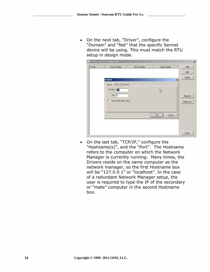
On the next tab, “Driver”, configure the “Domain” and “Net” that the specific Sennet
device will be using. This must match the RTU setup in design mode.
On the last tab, “TCP/IP,” configure the “Hostname(s)”, and the “Port”. The Hostname
refers to the computer on which the Network
Manager is currently running. Many times, the Drivers reside on the same computer as the
network manager, so the first Hostname box will be “127.0.0.1” or “localhost”. In the case
of a redundant Network Manager setup, the user is required to type the IP of the secondary
or “mate” computer in the second Hostname box.

_______________________ Senstar Sennet / Starcom RTU Guide Ver 3.x ______________________
Copyright © 1999- 2012 OSSI, LLC. 25
At this point, click “OK”, and the Driver Service
window will now have a new Sennet driver added to its list.
_______________________ Senstar Sennet / Starcom RTU Guide Ver 3.x ______________________
Copyright © 1999- 2012 OSSI, LLC. 26
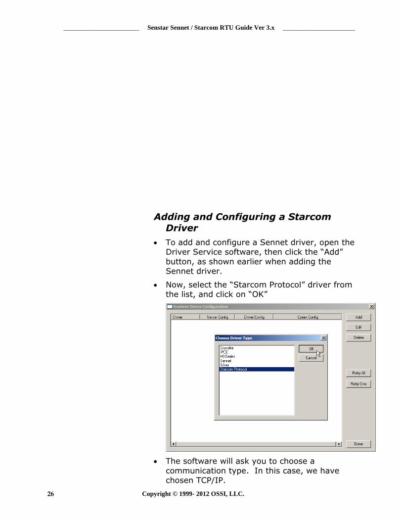
Adding and Configuring a Starcom Driver
To add and configure a Sennet driver, open the Driver Service software, then click the “Add”
button, as shown earlier when adding the Sennet driver.
Now, select the “Starcom Protocol” driver from the list, and click on “OK”
The software will ask you to choose a
communication type. In this case, we have chosen TCP/IP.

_______________________ Senstar Sennet / Starcom RTU Guide Ver 3.x ______________________
Copyright © 1999- 2012 OSSI, LLC. 27
At this point the driver configuration tabs will appear, and in the first tab, “Server”, type in
the “Host Address” computer name, which will be the computer running the Intelli-Site server
software. If running redundant servers, the correct notation in this box is
“Server1,Server2” (no spaces, and without
quotes)

_______________________ Senstar Sennet / Starcom RTU Guide Ver 3.x ______________________
Copyright © 1999- 2012 OSSI, LLC. 28
On the second tab, “Starcom”, the user will
select the “Enabled” box in the “Senstar 100
Emulation” section, if the intended device is made to communicate with a Senstar 100. (See
device manufacturer for details). The “Server Ack Required” option, requires the driver to hang
on to the alarm that comes in from the field device until the Intelli-Site server has
acknowledged receipt of the alarm. This is an optional checkbox, but can be useful in a
redundant server environment where failovers may occur.

_______________________ Senstar Sennet / Starcom RTU Guide Ver 3.x ______________________
Copyright © 1999- 2012 OSSI, LLC. 29
On the next tab, “Driver”, configure the “Domain” and “Net” that the specific Starcom
device will be using. This must match the RTU setup in design mode.
On the last tab, “TCP/IP,” configure the
“Hostname(s)”, and the “Port”. The Hostname refers to the IP of the Starcom device. Make
sure to use the correct port number, as preconfigured in the device itself.

_______________________ Senstar Sennet / Starcom RTU Guide Ver 3.x ______________________
Copyright © 1999- 2012 OSSI, LLC. 30
At this point, click “OK”, and the Driver Service window will now have a new Starcom driver
added to its list.