senior in architectural engineering structural option mae… · senior in architectural engineering...
TRANSCRIPT

Robert S. Whitaker
Senior in Architectural Engineering Structural Option
MAE/ BAE Pennsylvania State University
Senior Thesis Project:
Parkview at Bloomfield Station Spring 2006
Faculty Consultant: Professor Parfitt

Robert S. WhitakerStructural OptionParkview at Bloomfield StationBloomfield, NJwww.arche.psu.edu/thesis/eportfolio/current/portfolios/rsw153/
Project Team:Owners: Toll Brothers, Inc.Architect: Minno and Wasko Structural Engineer: Cates Engineering Pre-cast Engineer: Unistress Corp. Civil Engineer: PMK Group MEP Engineer: R.W. Sullivan, Inc. Contractor/ CM: Bovis - lend lease
Structural•Floor system: 16” Hambro Floor System w/ 3” slab•Interior Bearing walls: 4” light gage shear walls w/
tube steel top plates•Exterior Bearing walls: 6” light gage shear walls w/
tube steel top plates•Columns: HSS 3x3x1/4” to HSS 7x3x3/8”•Beams: typical beam is a W10x12, HSS 4x4x5/16”,
or HSS 6x4x5/16”•Roof: light gage roof trusses w/ portions of flat roof•Foundation: continuous grade beam footing•Garage foundation: 100 ton H piles 42-53 ft deep
Architectural• 6 story residential building surrounding a pre-cast parking garage
• Long irregular footprint• 197 condominium units & a 330 space garage•Building is nestled between Second River, Washington St, and a Midtown Line train station
•The exterior wall cladding is an Exterior Finish and Insulation System (EFIS)
•Gable roof with either a 12:12 or 8:12 slope
General information•Cost:
Overall Project: $65,616,081Building: $56,936,063Pre-cast Garage: $8,680,018
•Project delivery method:Qualified Design-Bid-Build
•Construction start-finish: November 10, 2005-TBD
Mechanical•Unit temperature controls•Gas fired furnaces•Air handling unit/condensing unit refrigerant loop
•Individual unit water heaters
Fire Protection•Wet sprinkler in main building•Dry sprinkler in garage & attic•1,500 GPM fire & jockey pumpSpecial Systems•15 panel point security system
Electrical•Electric baseboard•125A 1P3W panels•2 building transformers•(2) 3000A switchboards•250 KW 120/208 diesel fired emergency generator
•Duct banks for CATV/Tele utilities
Transportation•(2) 2,500lbs & (1) 3,500lbs elevator
•Six full stair towers
Codes•IBC 2000 NJ•Fair Housing
Use Group•Building:R2•Garage:S-2
SizeTotal: 453,473 ft2Building: 300,725 ft2Garage: 152,748 ft2
Table of Contents Parkview at Bloomfield Station
ii
Abstract
Table of Contents
Executive Summary
Introduction/ Acknowledgements
Section I: Existing Building Description
• Building Overview a. Building Envelope b. Type of Construction c. Electrical System d. Lighting System e. Mechanical System f. Fire Protection and Plumbing g. Other Building Systems
• Original Structural System a. Building Framing b. Hambro® Floor Framing c. Site and Foundations
• Building Parameters a. Original Design Theory b. Building Code References c. Building and Site Restrictions
Section II: Structural Depth Analysis
• New Design Overview a. Architectural Changes b. Gravity Structural Changes c. Lateral Changes
• New Design a. Design Criteria b. Structural Analysis c. RAM Model
• Bar Joist on Steel Girders
i
ii
1
2
I-3
I-4
I-7
I-10
II-13
II-14 II-17 II-17 II-17 II-19
• Steel columns • Lateral Frames • Spread Footings

Table of Contents Parkview at Bloomfield Station
iii
• Review of Design Criteria
• Vibration analysis
Section III: Breadth Studies
• Executive Summary • Cost Advantages
a. Footings b. Columns c. Floor System d. Wall System e. Conclusion
• EIFS Recommendations a. Background b. Benefits c. Problems d. Possible Solutions e. Conclusion
Section IV: Conclusion
Section V: Appendices
Building Summary Calculations, Figures, Tables, and Charts Index Calculations Section References and Bibliography
II-24
II-25
III-29
III-30 III-31
III-36 IV-41
V-44
V-45 V-50 V-52 V-75

I-1
Senior Thesis Final Report By Robert Whitaker
Executive Summary This thesis presents the process taken to create a new design for Parkview at
Bloomfield Station, a residential building located in Bloomfield, New Jersey. The summary of the original design is introduced and the initial design requirements are laid out. From here, the new structural system is created and analyzed based on structural and architectural requirements. Finally, two breadth topics are introduced to determine the new buildings cost advantage and cladding as compared to the original design.
Original Design
The original structural system is composed of light gage roof trusses, panelized bearing light gage walls, 16" deep D500 Hambro® floor joists, and 38 shear walls in the main lateral force resisting system. The precast garage at the center of the building is structurally separate, and only the 4" building separation is considered for story drift.
New Structural Design
The analysis of a new steel braced frame design is conducted to replace the current light gage bearing wall system. The most recent codes are used in the design analysis, updating the codes used in the original design. From the two different framing orientations analyzed, the 20K9 bar joist floor system spanning 38'-0" was concluded to be the most efficient and compatible design. Furthermore, the use of the braced frame system requires less lateral frames than the original system, creating the use of gravity frames at some unit separation locations. This helps to preserve the architecture of the living units while allowing for changes in future use. The foundation system in the new design is composed of spread footings that replace the original strip footings. In addition to these structural issues, a vibration analysis on the bar joist system shows that the floor is over the design limits but can still be considered acceptable.
Breadth Overview
This section investigates two breadth topics that effect large portions of Parkview at Bloomfield Station. First, the effect of changing from a Hambro® system to the new bar joist on steel frame system had on the cost and schedule is analyzed to show that the new system has cost benefits and better sequencing flexibility than the original system. Secondly, an analysis of the current Exterior Insulation and Finish System (EIFS) is studied and shown that a drainable EIFS system is the best solution.
I-2
Introduction
Architectural Engineering is a five year program at Penn State University that develops engineers to become well versed in a main area of study and sufficiently adept in three other areas pertinent to the building industry. The four areas of study offered are structural engineering, mechanical engineering, lighting/electrical design engineering, and construction management.
I have elected to study structural engineering as my main area of study. However,
this report does not cover all areas of training that I have received in my five years at Penn State, but focuses in on the areas of knowledge that were pertinent to the building presented. Similarly, the breadth of topics included at the end of this report represent a small portion of the accumulated knowledge learned from the mechanical, lighting/electrical, construction management and other various courses taken at Penn State.
Acknowledgements/ Credits
I would like to thank the following people for their help and support with my senior thesis:
Professor Parfitt Professor Hanagan Professor Memari Professor Schneider Professor Geschwindner Professor Bowers
All the PSU Faculty and Staff
Cates Engineering Michael Stansbury
Toll Brothers, Inc. Minno & Wasko
Lauren Whitaker ~ my wife
My Family Jesus
Robert S. Whitaker
Senior in Architectural Engineering Structural Option
MAE/ BAE Pennsylvania State University
Senior Thesis Project:
Parkview at Bloomfield Station Spring 2006
Section I
Existing Building Description
Faculty Consultant: Professor Parfitt
I-3
Senior Thesis Final Report By Robert Whitaker
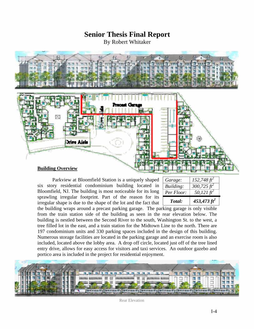
Building Overview Parkview at Bloomfield Station is a uniquely shaped
six story residential condominium building located in Bloomfield, NJ. The building is most noticeable for its long sprawling irregular footprint. Part of the reason for its irregular shape is due to the shape of the lot and the fact that the building wraps around a precast parking garage. The parking garage is only visible from the train station side of the building as seen in the rear elevation below. The building is nestled between the Second River to the south, Washington St. to the west, a tree filled lot in the east, and a train station for the Midtown Line to the north. There are 197 condominium units and 330 parking spaces included in the design of this building. Numerous storage facilities are located in the parking garage and an exercise room is also included, located above the lobby area. A drop off circle, located just off of the tree lined entry drive, allows for easy access for visitors and taxi services. An outdoor gazebo and portico area is included in the project for residential enjoyment.
Garage: 152,748 ft2 Building: 300,725 ft2 Per Floor: 50,121 ft2
Total: 453,473 ft2
Rear Elevation
I-4
Building Envelope
The roof system consists of asphalt shingle roofing over metal deck and fire rated plywood. The light gage roof trusses have either a 12:12 slope or 8:12 slope for gable roofs, with portions in the middle acting as a flat roof. Standing seam copper roof is used in some areas. The main body of the roof consists of hip roof conditions accented with gable roof sections over balcony areas. The exterior wall cladding is an Exterior Finish and Insulation System (EFIS) over light gage walls. Anderson vinyl windows and entry doors also make up parts of the wall system. The wall along the train line consists mainly of the open precast garage panels.
Type of Construction
Site work includes existing building demolition, grading, importing fill and
locating new utilities. It will also include installation of fountains, gazebo and a portico. The construction of the parking garage will be completed first, using a crane to lift the precast double T shapes into place. Upon completion of the parking garage the panelized light gage walls will be lifted into place and anchored with the floor system. The delivery method is a qualified design-bid-build for both the building and the parking garage. The total building cost is $65,616,081, not including a CM bond. Electrical System
The electrical panels are sized at 125A 1P3W, and there are two building transformers. Secondary service includes feeders in GRC conduit from the utility company transformers to the (2) 3000 amp switchboards. Apartment services are fed from meter centers located on each floor at 2 locations, with 125 amp feeders to each apartment load center with 3C#1 armored interlock cables. The emergency generator is a 250 KW 120/208, diesel fired with an 800 amp ATS. The HVAC equipment in the units is based on (1) 20/3p feed to the HWH/HVAC unit, and the electric range and dryer are each supplied with 50/2P feeds. Each unit is accessed with (1) ¾” conduit from the Tele/Com closet and (1) 1” pull wire conduit for CATV requirements. The electrical system includes the incoming duct banks for Electrical/CATV/Tele utilities, all to be concrete encased with pulled wires. Also included in the outfitting of the building and garage area are the lighting, HVAC, FA, telephone and CATV systems. Lighting System
There is lighting located exteriorly at the fountain, gazebo, and portico. In addition, site lighting includes pole fixtures, and the access point of the existing (2) 5” PVC utility line. Interior lighting consists of MC cabling and EMT within garage areas. Temporary lighting and power is included.
I-5

Mechanical System
The HVAC system includes sheet metal ducts covered in 1 ½” insulation, insulation board on the exterior walls, unit temperature controls, refrigerant piping, water heaters, condensate drain piping, grd’s testing and balancing, and rigging. Electric base board, air handling units, gas fired furnaces and air cooled condensing units compose the HVAC system. There is a refrigerant loop between air handling units and condensing units. Hot water from hot water heaters is sent to air handling units for use in heating air. The exhaust fan is a Nutone LS80 (with no lights). Fire Protection and Plumbing
The fire protection system includes a fire pump, wet sprinkler system and a dry sprinkler system in the attic area. The garage will have a dry sprinkler system. The wet fire protection system is connected to a 6” combination water main, installed with a 1,500 GPM fire pump and jockey pump. There is a fire department connection on the west side of the building to the fire protection room. The dry systems in the attic and garage are on a connected system and branched from this room. The dry system will be installed with galvanized steel pipe. The floor mains and branches will be orange CPVC with sprinkler heads concealed in the plaster ceiling.
The building plumbing includes a sanitary system, natural gas, domestic water with booster pump, plumbing fixtures, gas hot water heaters, washing machine indirect waste and water heater indirect waste. The main utility room is located outside the 2nd floor trash room. The garage includes storm water and oily water drains, non-freeze wall hydrants connected to the condo building and domestic water. The sanitary system is composed of schedule 40 PVC pipe and drainage fittings. The natural gas system is based on a load of 70 CFH per hot water heater. It is supplied from a 10” line from the source and branches off into schedule 40 black steel pipes varying in size from 8” to 3” with 2” valve taps for single risers. Domestic water is brought in through a 6” pipe with water meter and backflow preventer. Once inside, it is split into (2) 4” mains for north and south halves. Main sizes vary from 4” down to 2” based on 14.5 WSFU per condo and velocity less than 8 FPS. A Triplex water booster pump is used to maintain the water pressure to upper floors. Plumbing fixtures are attached with type DWV copper piping. The hot water heater is a direct vent with a 75 gallon storage capacity and a 100 GPH recovery. Other Building Systems
Telephone and CATV outlets are provided for each living unit. There are six stair wells that have access to all six levels of the building, and access to all floors from the 6 story attached parking garage. In addition, there are (2) 6-stop 2,500lbs elevators and (1) 6-stops 3,500lbs elevator. Finally, a security system terminal is located at the main entrance as well as fourteen additional locations with panel points. Further, there is one overhead electric security parking door at the garage.
I-6
Original Structural System
Building Framing
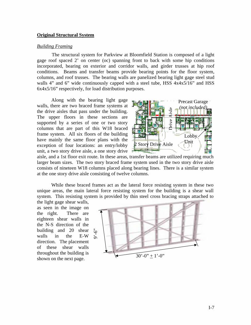
The structural system for Parkview at Bloomfield Station is composed of a light gage roof spaced 2’ on center (oc) spanning front to back with some hip conditions incorporated, bearing on exterior and corridor walls, and girder trusses at hip roof conditions. Beams and transfer beams provide bearing points for the floor system, columns, and roof trusses. The bearing walls are panelized bearing light gage steel stud walls 4” and 6” wide continuously capped with a steel tube, HSS 4x4x5/16” and HSS 6x4x5/16” respectively, for load distribution purposes.
Along with the bearing light gage
walls, there are two braced frame systems at the drive aisles that pass under the building. The upper floors in these sections are supported by a series of one or two story columns that are part of this W18 braced frame system. All six floors of the building have mainly the same floor plans with the exception of four locations: an entry/lobby unit, a two story drive aisle, a one story drive aisle, and a 1st floor exit route. In these areas, transfer beams are utilized requiring much larger beam sizes. The two story braced frame system used in the two story drive aisle consists of nineteen W18 columns placed along bearing lines. There is a similar system at the one story drive aisle consisting of twelve columns.
Precast Garage (not included)
2 Story Drive Aisle
Driv
eA
isle
Lobby Unit
While these braced frames act as the lateral force resisting system in these two
unique areas, the main lateral force resisting system for the building is a shear wall system. This resisting system is provided by thin steel cross bracing straps attached to the light gage shear walls, as seen in the image on the right. There are eighteen shear walls in the N-S direction of the building and 20 shear walls in the E-W direction. The placement of these shear walls throughout the building is shown on the next page.
30’-0” + 1’-0”
9’-6
”
I-7

I-8
Prec
ast G
arag
e
Drive Aisle
Driv
e A
isle
Shea
r W
all L
ocat
ions

Hambro® Floor Framing
A 16” deep Hambro® D500™ floor system makes up the composite rigid floor diaphragm and consists of joists spaced at 4’-1¼” oc connected to a 3” concrete floor (3000psi). The 4’-1¼” joist spacing is based on the standard dimensions of a plywood panel. This method of formwork is discussed in more detail in Section III: Breadth Studies ~ Cost Advantages. The bottom chord (Fy = 50,000psi min.) acts as a tension member in the concreting stage and during the service life of the floor. The Hambro web system tying the top and bottom chords consists of bent rods (Fy = 44,000psi min.) and resists vertical shear in a conventional truss manner. The patented 13 gage top chord (Fy = 50,000psi min.) acts as a compression member during the non-composite stage.
Hambro Floor System Note: Typical bearing walls are light gage walls (not those shown above)
In the composite stage, the top chord (including an “S” shape extension that is embedded in the concrete) functions as a continuous shear connector. The concrete slab is supported during the concrete pour by reusable plywood panel forms. The forms are located between joists and braced by ROLLBARS® that are held in place by holes in the top chord of the joist. The concrete slab is reinforced with a 6x6 welded wire mesh system. The “S” on the top chord functions as a high chair for this wire mesh, developing the negative moment capacity in the composite system which produces the effect of a continuous one-way reinforced slab over the joists. The 16” Hambro joists span the short direction of the living units (typically 30’ + 1’-0”) and Hambro RTC joists (top cord only joists) span and support the corridor (typically 6’). The total ceiling to floor depth is 21” including the drop ceiling depth. Also, the joist system allows the mechanical duct work to pass through the open webs of the joists.
The precast garage, located at the center of the building, consists of precast
double-T planks bearing on precast load bearing elements. The vertical elements in the garage transfers its’ load to pile caps encompassing 100 ton H piles drilled to bedrock (ranging from 42-53 feet below the slab-on-grade surface). The precast garage is structurally separated from the main building by a 4” air gap and by 4” expansion joints at building connection points. Because of this the garage will not be considered in the new building design and will remain the same.
I-9
Site and Foundations The site where the building sits is in Bloomfield, NJ which is located along the
east coast near New York City. This site is close to Second River and contains a modest level of top soil that has been deposited by the river over the course of years. This layer needs to be scraped off prior to the placement of the foundation. The soil below this top soil level has an allowable bearing capacity of 3000 psf. The frost depth for this area is 4’-0” and will further necessitate the removal of upper layers of soil. The site is located at the center of an east coast seismic epicenter. Furthermore, since the site is located near the coast line it experiences greater wind speeds.
Finally, continuous 2’-6” wide footings make up most of the building bearing
wall support under the 4” slab-on-grade foundation. However, larger spread footings (typically 4’x 4’) are utilized below leaning column point loads. The spread footings supporting the one and two story drive aisle columns merge together and resemble larger single spread footings. Yet, out of the entire building there are only 43 isolated spread footings including the drive aisle columns. This small number of isolated footings is partially due to the fact that the continuous footings support the smaller tube steel column loads. The foundation of the parking garage encompasses a deep foundation system rather than the main buildings shallow footing system. Since the deep foundation will not be relying on the same soil as the main building and the footings of the precast garage are separate from that of the main building’s foundation, they were ignored in the initial building design.
Building Parameters
Original Design Theory
The design theory used in the original analysis of Parkview at Bloomfield Station was Allowable Stress Design (ASD). The beam calculations were designed using American Institute of Steel Construction (AISC) 9th Edition ~ ASD and designed using the Enercalc® program (ASD based). The tube steel columns were also designed based on the column tables in chapter 3 of the AISC 9th Edition ~ ASD manual. Building Code References
The original design of the structure was in accordance with the International
Building Code (IBC) 2000 with New Jersey amendments, the New Jersey Uniform Construction Code, and local county and township requirements. IBC 2000 used design loads specified in ASCE 7 for both gravity and lateral loadings. Furthermore, the New Jersey amendments to IBC 2000 did not create any changes to the structural code requirements of IBC 2000, but focused more on non-structural issues. In addition, no changes to the structural design requirements were added by the New Jersey Uniform Construction Code or any of the local requirements.
I-10
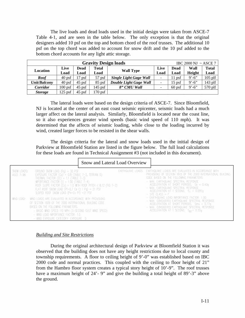
The live loads and dead loads used in the initial design were taken from ASCE-7 Table 4-1, and are seen in the table below. The only exception is that the original designers added 10 psf on the top and bottom chord of the roof trusses. The additional 10 psf on the top chord was added to account for snow drift and the 10 psf added to the bottom chord accounts for any light attic storage.
Gravity Design loads IBC 2000 NJ ~ ASCE 7
Location Live Load
Dead Load
Total Load Wall Type Live
Load Dead Load
Wall Height
Total Load
Roof 40 psf 17 psf 57 psf Single Light Gage Wall - 11 psf 9’-6” 105 plf Unit/Balcony 40 psf 45 psf 85 psf Double Light Gage Wall - 15 psf 9’-6” 143 plf
Corridor 100 psf 45 psf 145 psf 8” CMU Wall - 60 psf 9’-6” 570 plf Storage 125 psf 45 psf 170 psf
The lateral loads were based on the design criteria of ASCE-7. Since Bloomfield, NJ is located at the center of an east coast seismic epicenter, seismic loads had a much larger affect on the lateral analysis. Similarly, Bloomfield is located near the coast line, so it also experiences greater wind speeds (basic wind speed of 110 mph). It was determined that the affects of seismic loading, while close to the loading incurred by wind, created larger forces to be resisted in the shear walls.
The design criteria for the lateral and snow loads used in the initial design of
Parkview at Bloomfield Station are listed in the figure below. The full load calculations for these loads are found in Technical Assignment #3 (not included in this document).
Building and Site Restrictions During the original architectural design of Parkview at Bloomfield Station it was
observed that the building does not have any height restrictions due to local county and township requirements. A floor to ceiling height of 9’-0” was established based on IBC 2000 code and normal practices. This coupled with the ceiling to floor height of 21” from the Hambro floor system creates a typical story height of 10’-9”. The roof trusses have a maximum height of 24’- 9” and give the building a total height of 89’-3” above the ground.
I-11
Snow and Lateral Load Overview
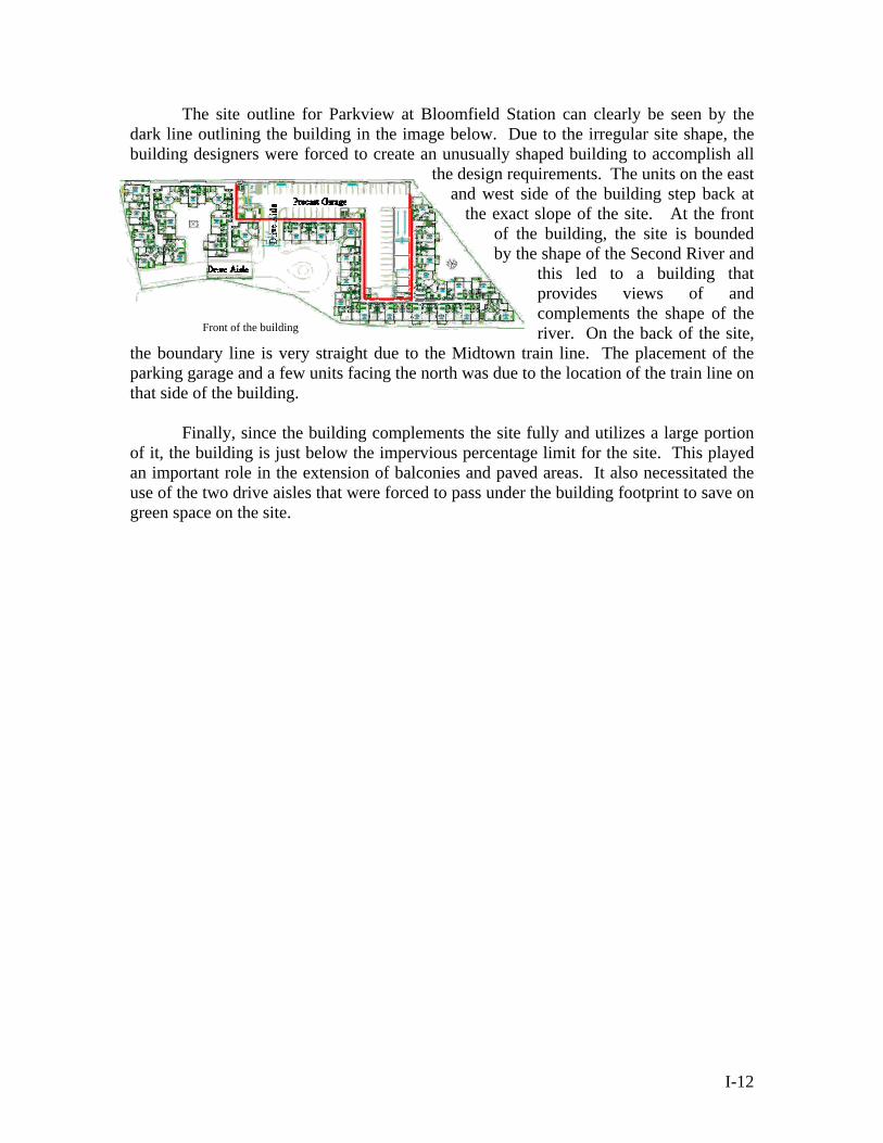
The site outline for Parkview at Bloomfield Station can clearly be seen by the dark line outlining the building in the image below. Due to the irregular site shape, the building designers were forced to create an unusually shaped building to accomplish all
the design requirements. The units on the east and west side of the building step back at
the exact slope of the site. At the front of the building, the site is bounded by the shape of the Second River and
this led to a building that provides views of and complements the shape of the river. On the back of the site,
the boundary line is very straight due to the Midtown train line. The placement of the parking garage and a few units facing the north was due to the location of the train line on that side of the building.
Front of the building
Finally, since the building complements the site fully and utilizes a large portion
of it, the building is just below the impervious percentage limit for the site. This played an important role in the extension of balconies and paved areas. It also necessitated the use of the two drive aisles that were forced to pass under the building footprint to save on green space on the site.
I-12

Robert S. Whitaker
Senior in Architectural Engineering Structural Option
MAE/ BAE Pennsylvania State University
Senior Thesis Project:
Parkview at Bloomfield Station Spring 2006
Section II
Structural Depth Analysis
Faculty Consultant: Professor Parfitt
II-13

Senior Thesis Final Report By Robert Whitaker
New Design Overview Architectural Changes
The new floor plan above reflects the changes made to the architectural layout of Parkview at Bloomfield Station due to the new structural system. It is nearly identical to the original design and has only changed within the walls between units and within the floor cavity.
The first change to the architecture was due to switching from the bearing light
gage wall system to a braced frame structure. This structural change imposes the need for wide flange columns to be placed within the space of the original 11” wall depth. This will generally not create a difference in wall size but in a few cases creates the need for larger wall sections at column locations. The increase in wall size ultimately deducts small amounts of square footage from the units that are affected. This change to the architecture of the units will be discussed in greater detail in the lateral system discussion in the Review of Design Criteria sub-section, later in this section.
The other change to the original architecture was that the ceiling to floor depth
increased from 21” to 25”. The original design had a floor to ceiling height of 9’-0” that was established based on IBC 2000 code and normal practices. This height combined with the ceiling to floor height of 21” from the Hambro floor system, produced a typical story height of 10’-9”. The roof trusses have a maximum height of 24’- 9” and produce a total height of 89’-3” above the ground. The new system uses the same floor to ceiling
II-14
height requirements and roof trusses, but the new building will have a total height of 91’-3”, a difference of 2 feet. The typical floor to floor height is 11’-1”.
In some buildings the non-modular 11’-1” floor to floor height would cause a
problem with claddings such as brick, but the new design incorporates a drainable Exterior Insulation and Finish System (EIFS) system. This system can be tailored to fit any dimension and will not have a problem with the non-modular nature of the structure. The difference between the new drainable EIFS and the original designs typical EIFS cladding is discussed in greater detail in Section III: Breadth Topics.
Gravity Structural Changes The new structure, while it still resembles the original system, is in fact quite
different. The first of these differences is that the original system used Hambro joists to span the 30 foot depth of the structure. This system needed intermediate bearing locations in some larger units and in some corner units. However, the new design spans the long direction of the unit, 38 feet. This enables the joists to span any unit without the need for intermediate framing locations while using the same joist depth. This allows for partition walls that can be placed at any location and can be completely removed if the use changes in the future.
Furthermore, since the new structure is not supported by the wall systems
between the units, the walls can be erected at a later time quickly, not needing the tube steel cap required for the original design. This saves on field welding and coordination between trades. The floor system can also be placed sooner and by the same crew that erects the steel frame. The wall placement is not as critical a step to the building sequencing in the new design.
The foundation in the new design looks significantly different than that of the
original design. The new design relies totally on spread footings to support the structure where as the original was predominately composed of strip footings that outlined a majority of the building. The main drawback for the new foundation system is that formwork will be required for the spread footings to ensure the proper coverage, as compared to the strip footings, used originally, that can be poured against the earth in most cases.
In addition, since both systems have advantages and disadvantages the difference
in the new design and other structural issues that were affected by the new design are further compared in Section III: Breadth Topics ~ Cost Advantages.
Lateral Changes The final difference in the new design with respect to the original design is the
lateral force resisting system. In this design the lateral forces, earthquake and wind forces, are resisted by braced frames made from wide flange shapes. These frames will
II-15
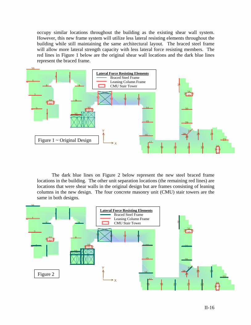
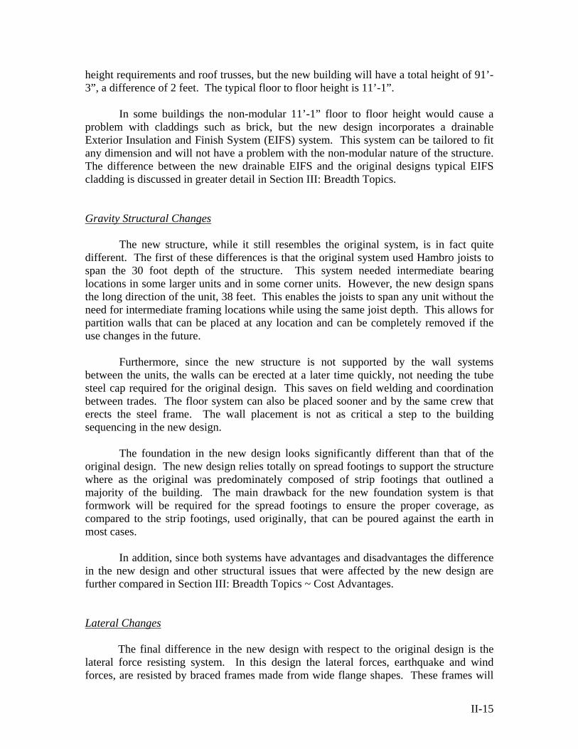
occupy similar locations throughout the building as the existing shear wall system. However, this new frame system will utilize less lateral resisting elements throughout the building while still maintaining the same architectural layout. The braced steel frame will allow more lateral strength capacity with less lateral force resisting members. The red lines in Figure 1 below are the original shear wall locations and the dark blue lines represent the braced frame.
Lateral Force Resisting Elements Braced Steel Frame
Leaning Column Frame CMU Stair Tower
Figure 1 ~ Original Design
The dark blue lines on Figure 2 below represent the new steel braced frame
locations in the building. The other unit separation locations (the remaining red lines) are locations that were shear walls in the original design but are frames consisting of leaning columns in the new design. The four concrete masonry unit (CMU) stair towers are the same in both designs.
Lateral Force Resisting Elements Braced Steel Frame
Leaning Column Frame CMU Stair Tower
Figure 2
II-16
New Design
Design Criteria As part of the new design criteria, the most recent code provisions available were
used in the design. The most significant change was utilizing ASCE 7-05 code instead of the ASCE 7-02 version that was used for the original design. This provision had the largest affect since it deals with structural issues such as the lateral loading. The other code update change that was made was the use of the International Building Code (IBC) 2003 rather than IBC 2000.
The second thing used as a basis for the new design criteria was to try to maintain
architectural integrity. Because of the building’s initial nearness to the impervious percentage limitation of the site and to the actual site boundary lines, there should be no extensions to the overall building footprint. The overall square footage of rentable space should be kept as close as possible to the original design in order to maintain the profitability of the project. Finally, the overall appearance of the project should be maintained, but minute changes to some details are aloud.
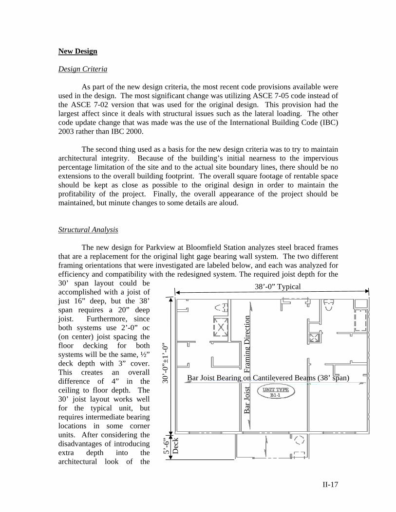
Structural Analysis The new design for Parkview at Bloomfield Station analyzes steel braced frames
that are a replacement for the original light gage bearing wall system. The two different framing orientations that were investigated are labeled below, and each was analyzed for efficiency and compatibility with the redesigned system. The required joist depth for the 30’ span layout could be accomplished with a joist of just 16” deep, but the 38’ span requires a 20” deep joist. Furthermore, since both systems use 2’-0” oc (on center) joist spacing the floor decking for both systems will be the same, ½” deck depth with 3” cover. This creates an overall difference of 4” in the ceiling to floor depth. The 30’ joist layout works well for the typical unit, but requires intermediate bearing locations in some corner units. After considering the disadvantages of introducing extra depth into the architectural look of the
38’-0” Typical
30’-
0”±1
’-0”
Bar
Jois
t
Fra
min
g D
irect
ion
Bar Joist Bearing on Cantilevered Beams (38’ span)
5’-6
” D
eck
II-17
II-18
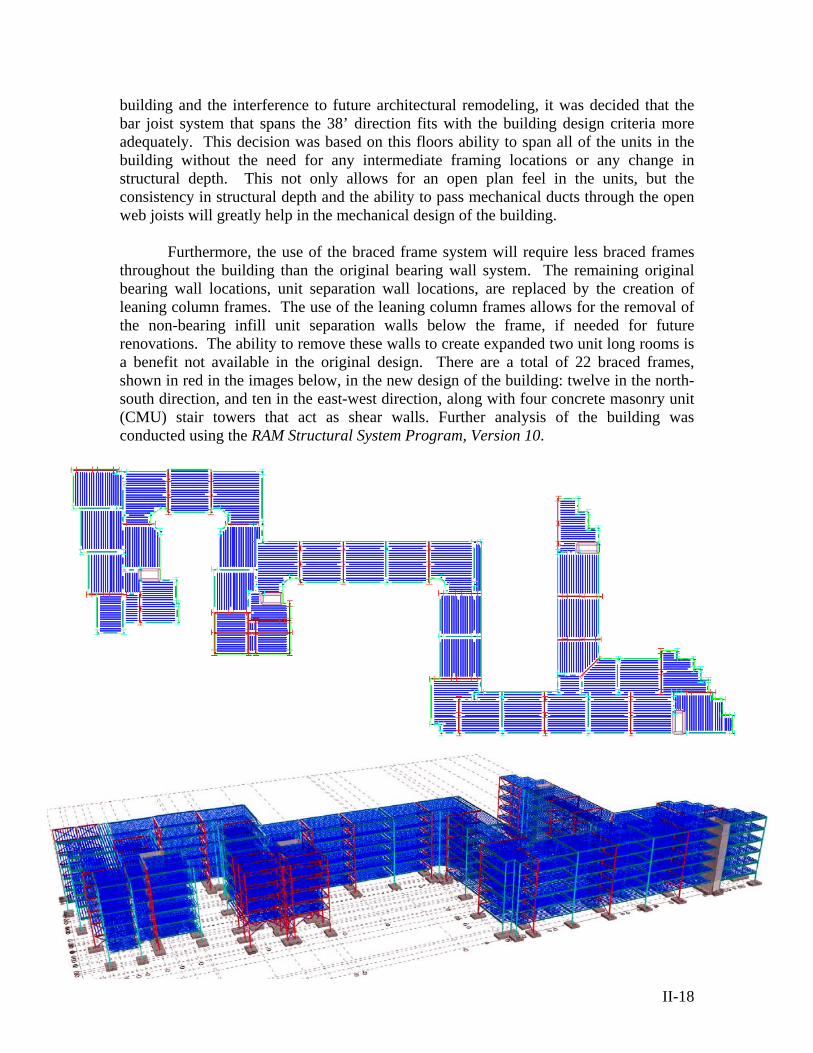
building and the interference to future architectural remodeling, it was decided that the bar joist system that spans the 38’ direction fits with the building design criteria more adequately. This decision was based on this floors ability to span all of the units in the building without the need for any intermediate framing locations or any change in structural depth. This not only allows for an open plan feel in the units, but the consistency in structural depth and the ability to pass mechanical ducts through the open web joists will greatly help in the mechanical design of the building.
Furthermore, the use of the braced frame system will require less braced frames
throughout the building than the original bearing wall system. The remaining original bearing wall locations, unit separation wall locations, are replaced by the creation of leaning column frames. The use of the leaning column frames allows for the removal of the non-bearing infill unit separation walls below the frame, if needed for future renovations. The ability to remove these walls to create expanded two unit long rooms is a benefit not available in the original design. There are a total of 22 braced frames, shown in red in the images below, in the new design of the building: twelve in the north-south direction, and ten in the east-west direction, along with four concrete masonry unit (CMU) stair towers that act as shear walls. Further analysis of the building was conducted using the RAM Structural System Program, Version 10.
II-19
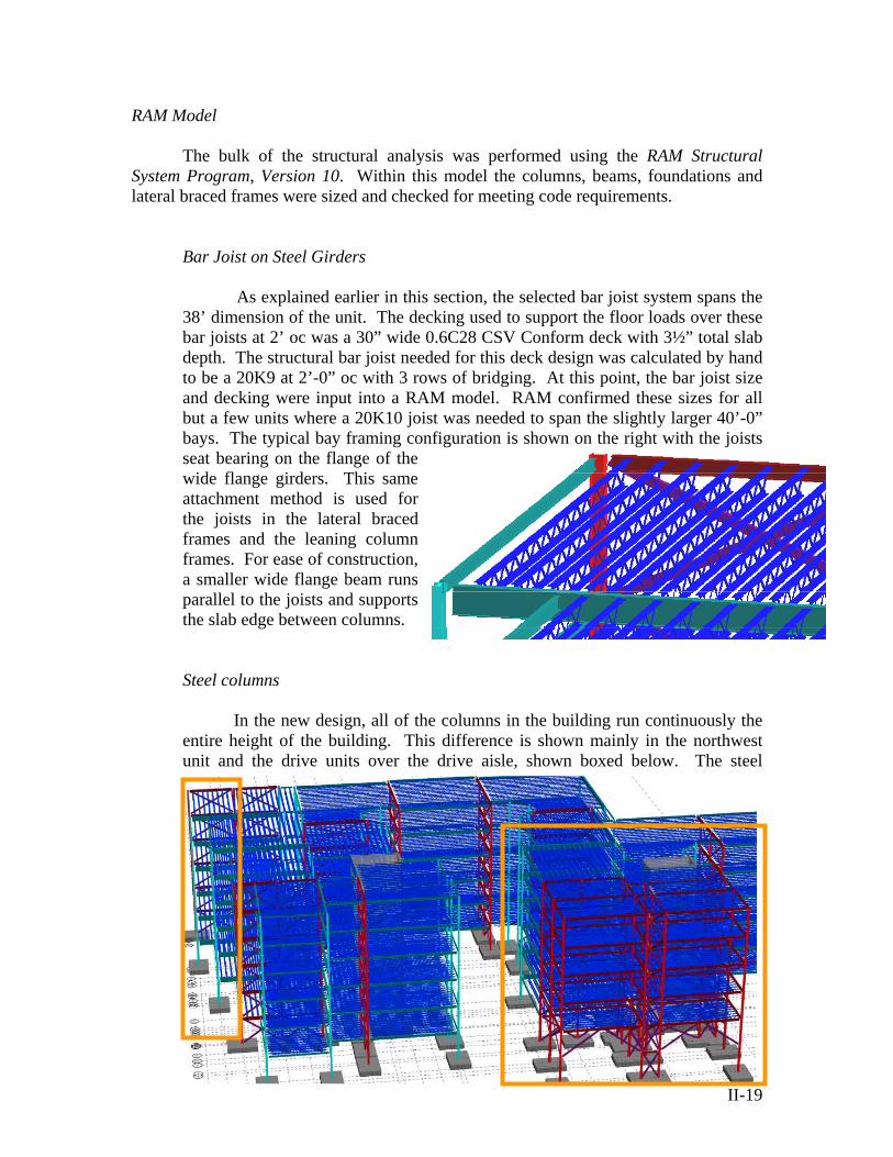
RAM Model The bulk of the structural analysis was performed using the RAM Structural
System Program, Version 10. Within this model the columns, beams, foundations and lateral braced frames were sized and checked for meeting code requirements.
Bar Joist on Steel Girders
As explained earlier in this section, the selected bar joist system spans the 38’ dimension of the unit. The decking used to support the floor loads over these bar joists at 2’ oc was a 30” wide 0.6C28 CSV Conform deck with 3½” total slab depth. The structural bar joist needed for this deck design was calculated by hand to be a 20K9 at 2’-0” oc with 3 rows of bridging. At this point, the bar joist size and decking were input into a RAM model. RAM confirmed these sizes for all but a few units where a 20K10 joist was needed to span the slightly larger 40’-0” bays. The typical bay framing configuration is shown on the right with the joists seat bearing on the flange of the wide flange girders. This same attachment method is used for the joists in the lateral braced frames and the leaning column frames. For ease of construction, a smaller wide flange beam runs parallel to the joists and supports the slab edge between columns. Steel columns
In the new design, all of the columns in the building run continuously the entire height of the building. This difference is shown mainly in the northwest unit and the drive units over the drive aisle, shown boxed below. The steel
II-20
columns throughout the building are composed of wide flange sections spliced at every 3rd story. This makes the lower column, generally a larger size than the upper, have a length of 38’-3” including a four foot length to the splice above the forth floor and the one foot extension to the foundation stem. The upper column section has a length of 29’-3” and terminates where the beams support the roof trusses.
There are a total of 84 gravity columns and 73 lateral columns in the
building. The gravity columns range in size from W10x33 to W12x65 with a typical column size of W10x33. The upper column sections of the gravity frames are almost entirely composed of W10x33 sections, leaving the majority of the column variation in the lower gravity column sections. Finally, the lateral columns are discussed in detail in the next sub-section. Lateral Frames
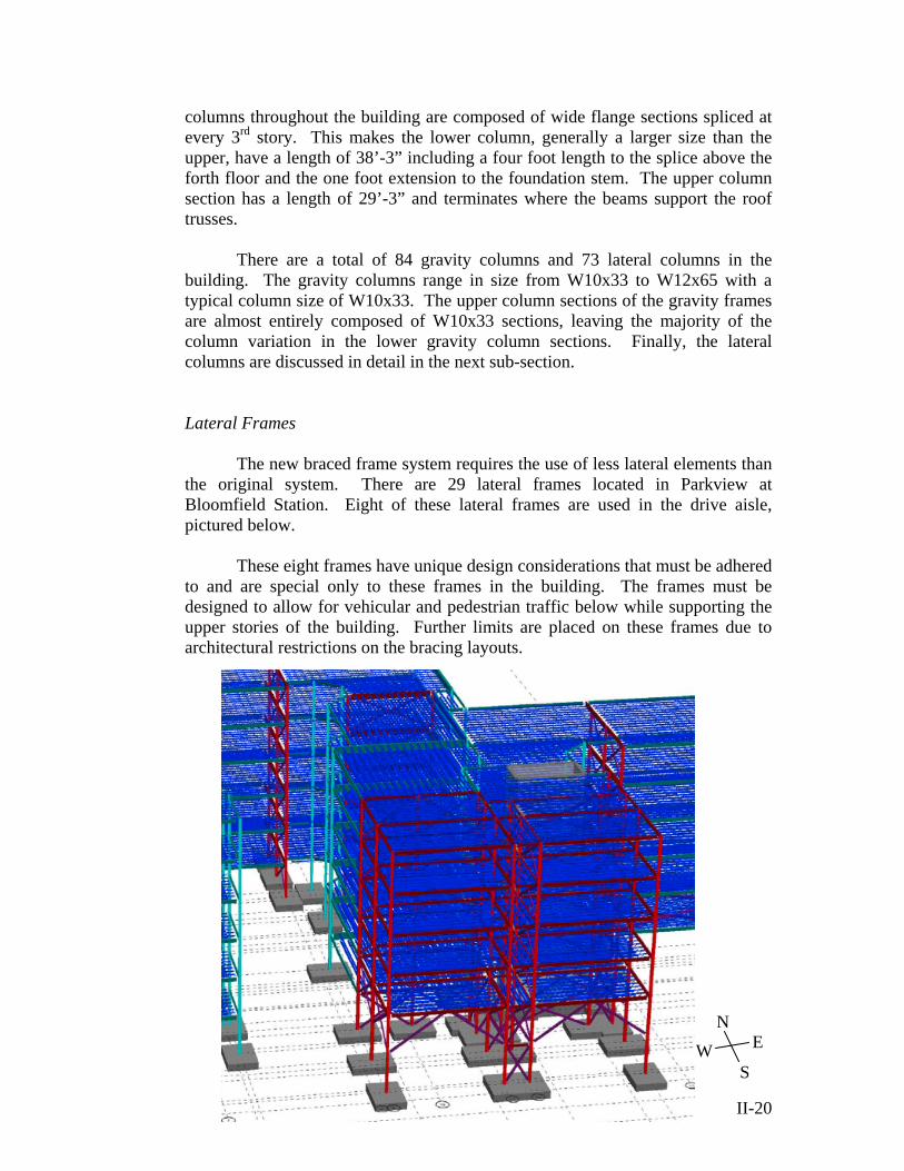
The new braced frame system requires the use of less lateral elements than the original system. There are 29 lateral frames located in Parkview at Bloomfield Station. Eight of these lateral frames are used in the drive aisle, pictured below.
These eight frames have unique design considerations that must be adhered
to and are special only to these frames in the building. The frames must be designed to allow for vehicular and pedestrian traffic below while supporting the upper stories of the building. Further limits are placed on these frames due to architectural restrictions on the bracing layouts.
NE
SW
II-21
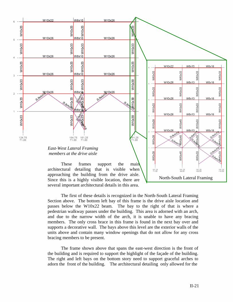
East-West Lateral Framing members at the drive aisle
These frames support the main
architectural detailing that is visible when approaching the building from the drive aisle. Since this is a highly visible location, there are several important architectural details in this area.
The first of these details is recognized in the North-South Lateral Framing
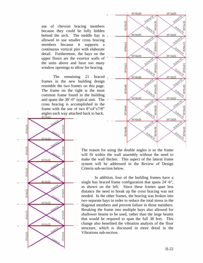
Section above. The bottom left bay of this frame is the drive aisle location and passes below the W10x22 beam. The bay to the right of that is where a pedestrian walkway passes under the building. This area is adorned with an arch, and due to the narrow width of the arch, it is unable to have any bracing members. The only cross brace in this frame is found in the next bay over and supports a decorative wall. The bays above this level are the exterior walls of the units above and contain many window openings that do not allow for any cross bracing members to be present.
The frame shown above that spans the east-west direction is the front of
the building and is required to support the highlight of the façade of the building. The right and left bays on the bottom story need to support graceful arches to adorn the front of the building. The architectural detailing only allowed for the
North-South Lateral Framing
II-22
use of chevron bracing members because they could be fully hidden behind the arch. The middle bay is allowed to use smaller cross bracing members because it supports a continuous vertical pier with elaborate detail. Furthermore, the bays on the upper floors are the exterior walls of the units above and have too many window openings to allow for bracing.
The remaining 21 braced
frames in the new building design resemble the two frames on this page. The frame on the right is the most common frame found in the building and spans the 38’-0” typical unit. The cross bracing is accomplished in the frame with the use of two 8”x4”x7/8” angles each way attached back to back.
The reason for using the double angles is so the frame will fit within the wall assembly without the need to make the wall thicker. This aspect of the lateral frame system will be addressed in the Review of Design Criteria sub-section below.
In addition, four of the building frames have a single bay braced frame configuration that spans 24’-6”, as shown on the left. Since these frames span less distance the need to break up the cross bracing was not needed. In the other frames, the bracing was broken into two separate bays in order to reduce the total stress in the diagonal members and prevent failure in those members. Breaking the frame into multiple bays also allowed for shallower beams to be used, rather than the large beams that would be required to span the full 38 feet. This change also benefited the vibration analysis of the floor structure, which is discussed in more detail in the Vibrations sub-section.

Most of the typical beams in the lateral frames are W12x26 and W16x26, but the beams range in size from W8x13 up to W18x40. The extra depth in the W16x26 is needed because this beam in the frame, like all the typical frames, needs to be cantilevered out six feet to support the corridor. This corridor cantilever is utilized in the gravity frames throughout the building as well.
Additionally, the lateral frame column sizes do not
change dramatically throughout the building. The columns in the project consist of a range from W10x33 up to W10x54. The typical lateral column size was the W10x33 which is similar to the gravity columns; however there is one lateral frame where a W14x398 was required. The location of this column is shown boxed in the image on the left. The size of this column was so large because of the building torsion that was introduced into that wing of the building and therefore a need to restrain the story deflection in this wing to less than 4” to avoid contact with the parking garage. This wing runs parallel to the parking garage and extends 172’-0” (four unit widths) while only being just over 36’-3” deep (unit and corridor). Since the section is long and narrow, it does not have
as much lateral stiffness as most of the building, and requires larger frames to support this building wing. Spread Footings
The foundation for Parkview at Bloomfield Station is composed of nearly
all spread footings. These spread footings range in size and depth significantly depending on the column type. The gravity columns have relatively square footings, while the lateral load bearing column footings blend together into a long footing that runs parallel with the frame.
The gravity loaded footings in the building range
the laterally loaded footings, as seen in the image on the left, tended to be
in size from 4’x4’x1½’ deep up to 14’x14’x2’ deep footings. The gravity footings carry much smaller loads and generally remained isolated, as can be seen in the image on the left. The smaller footings in the project are very similar in size to the leaning (gravity loaded only) columns in the original design.
Conversely,
II-23
Gravity column and footing (typ)
Lateral column and footing (typ)

II-24Section: Braced Frame (2 Options)
much longer in the direction of the frame in order to resist the overturning moment. Since, the length in this direction is so great, these footings are poured and designed as a long spread footing with three column point loads. Due to this fact, the combined spread footings for the lateral frames range in size from 9’x30’-6’x1’-2” deep for the single bay frames up to 14’x36’x3’ deep for the double bay frames. Nevertheless, there are some lateral column foundations that remained isolated in the drive aisle locations. These spread footings range in size from 5’x5’x1½’ deep up to 8’x14’x2’ deep. A further look into the affect that the new spread footings have on the building’s cost is analyzed in Section III: Breadth Topics ~ Cost Advantages.
Review of Design Criteria
In order to meet the new design criteria, the most recent code provisions available
were used in the design of Parkview at Bloomfield Station. ASCE 7-05 code was utilized along with the use of Load and Resistance Factor Design (LRFD) in all calculations. Gravity floor loads and lateral loads were calculated from chapters 3, 4, 6, 7, and 9 of ASCE 7-05. The analysis of the building’s structure was performed by using the current RAM program version (Version 10). This program performed lateral load calculations, including seismic and wind from three directions, and computed the loads for the lateral frames in the building in accordance with the ASCE 7-05 code. A building drift limit was set at 4” and members were computed using the RAM program, based on sizes from the Manual of Steel Construction ~ 3rd Edition. Other allowable changes that were made to the architecture were verified by the International Building Code (IBC) 2003 and the New Jersey provisions to this code.
The second design criterion for the new design was to try to maintain the initial
architectural intent for the building. Furthermore, no extensions to the overall building footprint were allowed due to the limitations on impervious percentage and the building’s proximity to the site boundary lines.
As mentioned earlier, the new
lateral frame columns in some instances were larger than the 11” allowable wall cavity. Efforts were taken to keep the braced frame within this 11” limit, and two options were developed as can be seen on the right. While both bracing systems, C-channel and double angles, fit within the wall cavity, the steel angles were selected due to the lower weight of the system. Furthermore, the columns of most of the braced frames fit within the wall. Yet, a few frames require an architectural change by requiring the
columns to be boxed out beyond the wall width. This column size requirement unfortunately reduces the amount of rentable space within the building and interferes with the second design criteria. The second design requirement states that the overall square footage of rentable space should be kept as close to the original design in order to maintain the profitability of the project.
In order to solve this problem, the additional room needed for these walls, to
frame out around the columns, will be taken out of the 6’ corridor spaces. The existing corridors are 1’-0” greater than required by the IBC 2003 and therefore a reduction of up to 1’-0” is allowable if necessary. This design decision to shift the units down slightly should be first checked with the owner and architect to see if this change is even necessary, or if the loss of an average of 2 square feet of living space per apartment unit is an allowable loss.
Finally, the floor to floor height is taller than the original design by 4”, creating a
new story height of 11’-1”. This height increase did not interfere with any of the local height code restrictions, but did create a building that is taller than the original by two feet. Yet, even though the overall appearance of the project was stretched vertically by an unnoticeable 4” per floor, the design was still able to maintain all other architectural detail requirements.
Vibration Analysis
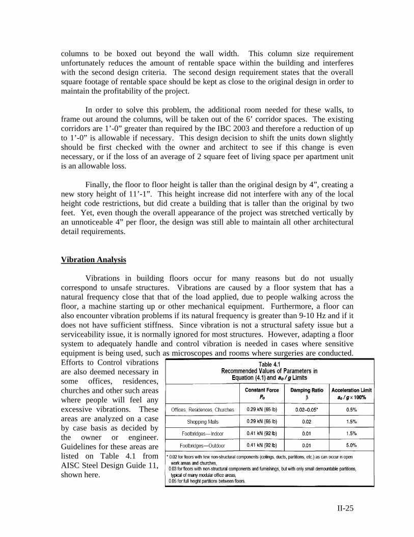
Vibrations in building floors occur for many reasons but do not usually correspond to unsafe structures. Vibrations are caused by a floor system that has a natural frequency close that that of the load applied, due to people walking across the floor, a machine starting up or other mechanical equipment. Furthermore, a floor can also encounter vibration problems if its natural frequency is greater than 9-10 Hz and if it does not have sufficient stiffness. Since vibration is not a structural safety issue but a serviceability issue, it is normally ignored for most structures. However, adapting a floor system to adequately handle and control vibration is needed in cases where sensitive equipment is being used, such asEfforts to Control vibrations are also deemed necessary in some offices, residences, churches and other such areas where people will feel any excessive vibrations. These areas are analyzed on a case by case basis as decided by the owner or engineer. Guidelines for these areas are listed on Table 4.1 from AISC Steel Design Guide 11, shown here.
microscopes and rooms where surgeries are conducted.
II-25
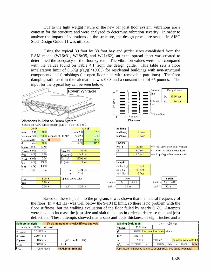
Due to the light weight nature of the new bar joist floor system, vibrations are a concern for the structure and were analyzed to determine vibration severity. In order to analyze
38 foot bay and girder sizes established from the RAM model (W16x31, W18x35, and W21x62), an excel spread sheet was created to determ
e floor (fn = 4.3 Hz) was well below the 9-10 Hz limit, so there is no problem with the floor s
the impact of vibrations on the structure, the design procedure set out in AISC Steel Design Guide 11 was utilized.
Using the typical 30 foot by
ined the adequacy of the floor system. The vibration values were then compared with the values found on Table 4.1 from the design guide. This table sets a floor acceleration limit of 0.5%g ((ao/g)*100%) for residential buildings with non-structural components and furnishings (an open floor plan with removable partitions). The floor damping ratio used in the calculations was 0.03 and a constant load of 65 pounds. The input for the typical bay can be seen below.
Column line
Column line
line Column
Based on these inputs into the program, it was shown that the natural frequency of
thtiffness, but the walking evaluation of the floor failed by nearly 0.6%. Attempts
were made to increase the joist size and slab thickness in order to decrease the total joist deflection. These attempts showed that a slab and deck thickness of eight inches and a
II-26

II-27
joist of 28 inches deep was the smallest design that would pass the 0.5% acceleration limit for the 38 foot span. With the eight inch slab and 28 inch joist, the floor to floor height would jump from 11’-1” to 12’-0” and the weight of the building would increase greatly.
Because of the vibration problem with the 38’ joist configuration, a check was
conducted for vibrations if the joists only needed to span 30 feet. The joist length was reduced to 30 feet and the slab and deck were reset to their original 3½” design depth. This time the joists had a higher natural frequency, yet still within the limits, but the walking evaluation for the system adequately passed. When the joists needed to span a shorter length, the deflection in the members reduced and created less vibrations.
Since the walking evaluation for this system passed the acceleration limit, it was
then examined against the vibration criteria for sensitivity equipment. This is the second

II-28
check that can be done for vibrations in a system. The criteria for this check are found in Table 6.1 from the design guide and are shown on this page. The floor vibration velocity is based on the speed of impacts across the floor. A fast walk is when a 185 pound test subject takes 100 steps per minute. A slow walk is when a 185 pound test subject takes 50 steps per minute. The moderate walk is in the middle of these two and is based on 75 steps per minute.
For slow walk, the 30’ system has an acceptable vibration velocity for laboratory
robots, computer systems, operating rooms, and microscopes up to 100x magnification.
While the value is close to the acceptable mid-span velocity, none of the activities are allowable at the moderate walking level. With these results as a base mark, the 38’ design can have added clarity by comparing these two systems. The slow walk vibration velocity for the 38’ design was calculated to be 11,690 x 10^-6 in/sec, which is close to the moderate walk level for the 30’ system.
With this new comparison, the 38’ design could be justified as being acceptable
even though it is outside the given acceleration limit (resonance response. Yet, converting the acceleration limit (a/g=.005) to a mid-span velocity shows that the maximum acceptable mid-span velocity is 71,545 micro-inches per second for the floor. This value is much lower than the calculated value of 157000 micro-inches per second from the a/g=.011 calculated. These values were determined using the equation V=a/(g*w) where w =2* p*fn. With this conversion showing that the resonance response controls the vibration of the floor system and that there are slight discrepancies in the code analysis between the transient response and the resonance response analysis for floors with a natural frequency around 4Hz. Alternative floor spans and stiffness may need to be used to correct this floor system. The full results of the vibration calculations are in the appendix of this document.
A judgment to accept the floor system as designed could be based on the fact that
the vibration issue is a service issue, and therefore based on the occupant’s opinion. The designed floor system is adequate structurally, and does not need to be converted to smaller bay sizes based on load. However, the final say for this decision is the owners.
Robert S. Whitaker
Senior in Architectural Engineering Structural Option
MAE/ BAE Pennsylvania State University
Senior Thesis Project:
Parkview at Bloomfield Station Spring 2006
Section III
Breadth Topics
Faculty Consultant: Professor Parfitt
III-29
Senior Thesis Final Report
Breadth Topics By Robert Whitaker
Breadth Topics
This section investigates two breadth topics that effect large portions of Parkview
at Bloomfield Station. First, the effect of changing from a Hambro® on bearing wall system to the new bar joist on steel frame system has on the cost and schedule is analyzed. Secondly, an analysis of the current Exterior Insulation and Finish System (EIFS) is studied.
Cost Advantages The bar joist structure bearing on a wide flange structure shows a $493,400
savings over the original Hambro on light gage bearing wall structure. In addition to the cost savings, there is also increased flexibility in the building sequencing such as allowing secondary crews to have access to an area quicker, not waiting on stripping formwork for reuse, and the fact that the structural progress is not dependant on the assembly of detailed light gage shear walls and tube steel. Therefore, the new design is the better option based on the assemblies’ level of detail, but this benefit must be weighed against the structural benefits of the original Hambro system.
Cladding Analysis An analysis of the original Exterior Insulation and Finish System (EIFS) façade is
checked for weather resistance and wall performance based on its uses in other buildings. After checking previous uses it is my recommendation that drainable EIFS is used at Parkview at Bloomfield Station rather than the original design for conventional EIFS. While the drainable EFIS cladding system is more expensive than the original system, it will ultimately pay dividends to the building owner in the long run. Both systems will fully work if attention to detail and installation is adhered to; yet, the drainable EIFS system allows a factor of safety for any minor mistakes that can be made during installation in the field or during design in the office through the inclusion of a water resistant membrane and drainage holes. Yet, in order for the drainable EIFS system to be effective for Parkview at Bloomfield Station, qualified laborers must be located and supervised to ensure a good product.
III-30
Cost Advantages Breadth Topic
Changing Structural Systems
The new structural system for Parkview at Bloomfield Station, while similar to the original system, incorporates regular k-series bar joists and metal decking rather than the specialized Hambro system that had no permanent decking requirements. The new system also relies on a wide flange structure and columns supported by larger spread footings. This is in stark contrast with the original system that utilized light gage bearing walls capped with steel tubes and supported by continuous footings. With these changes made to the structural systems, there needs to be a change made to the overall cost of the building. The new structural system will inevitably have a different effect on cost than the original system.
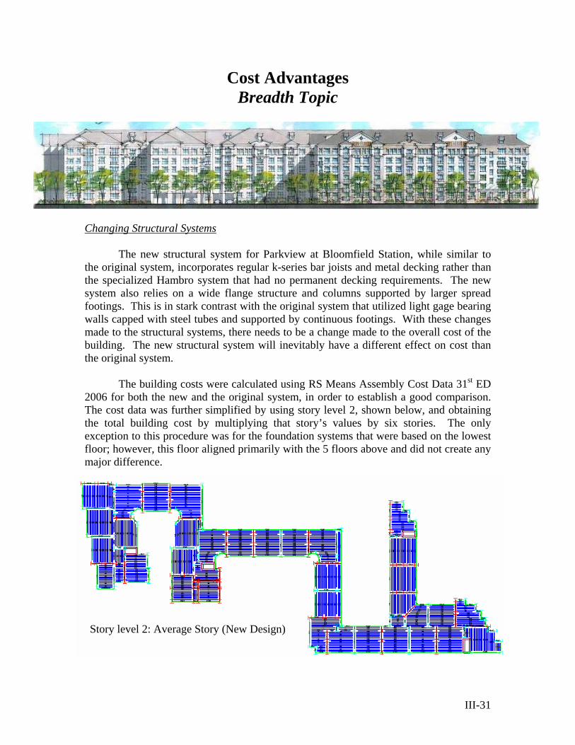
The building costs were calculated using RS Means Assembly Cost Data 31st ED
2006 for both the new and the original system, in order to establish a good comparison. The cost data was further simplified by using story level 2, shown below, and obtaining the total building cost by multiplying that story’s values by six stories. The only exception to this procedure was for the foundation systems that were based on the lowest floor; however, this floor aligned primarily with the 5 floors above and did not create any major difference.
Story level 2: Average Story (New Design)
III-31
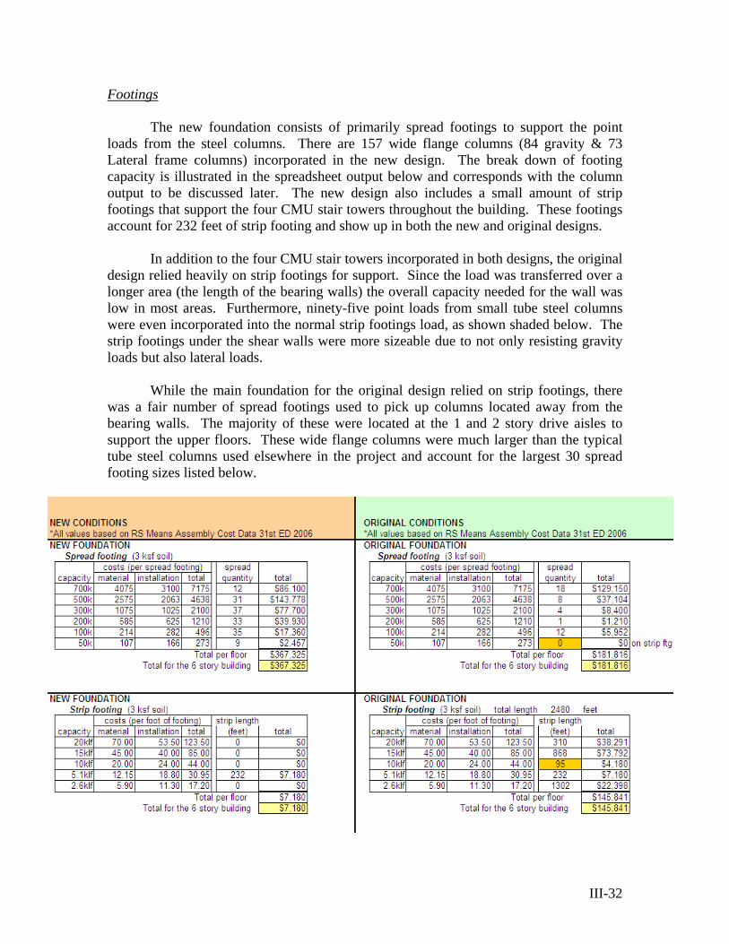
Footings The new foundation consists of primarily spread footings to support the point
loads from the steel columns. There are 157 wide flange columns (84 gravity & 73 Lateral frame columns) incorporated in the new design. The break down of footing capacity is illustrated in the spreadsheet output below and corresponds with the column output to be discussed later. The new design also includes a small amount of strip footings that support the four CMU stair towers throughout the building. These footings account for 232 feet of strip footing and show up in both the new and original designs.
In addition to the four CMU stair towers incorporated in both designs, the original
design relied heavily on strip footings for support. Since the load was transferred over a longer area (the length of the bearing walls) the overall capacity needed for the wall was low in most areas. Furthermore, ninety-five point loads from small tube steel columns were even incorporated into the normal strip footings load, as shown shaded below. The strip footings under the shear walls were more sizeable due to not only resisting gravity loads but also lateral loads.
While the main foundation for the original design relied on strip footings, there
was a fair number of spread footings used to pick up columns located away from the bearing walls. The majority of these were located at the 1 and 2 story drive aisles to support the upper floors. These wide flange columns were much larger than the typical tube steel columns used elsewhere in the project and account for the largest 30 spread footing sizes listed below.
III-32
The foundation systems both support the loads from the building, but the new foundation has slight cost and time ramifications. This is due to the fact that spread footings have a higher installation cost due to the need for formwork and deeper holes, causing them to be more expensive in most cases. Furthermore, the foundation for the new structural system has a higher cost by nearly $47,000 due to the larger number of spread footings required and larger quantities of concrete needed. However, since both structural systems use this type of footing the delay in the new system’s schedule is not a major concern.
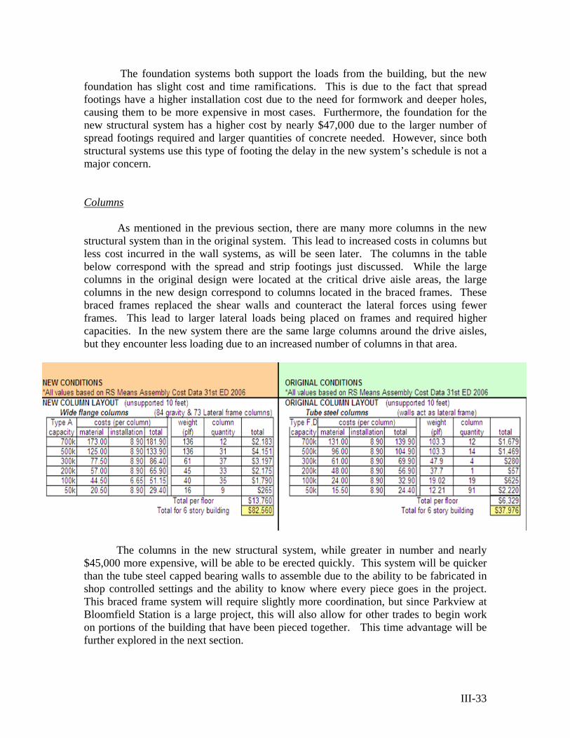
Columns As mentioned in the previous section, there are many more columns in the new
structural system than in the original system. This lead to increased costs in columns but less cost incurred in the wall systems, as will be seen later. The columns in the table below correspond with the spread and strip footings just discussed. While the large columns in the original design were located at the critical drive aisle areas, the large columns in the new design correspond to columns located in the braced frames. These braced frames replaced the shear walls and counteract the lateral forces using fewer frames. This lead to larger lateral loads being placed on frames and required higher capacities. In the new system there are the same large columns around the drive aisles, but they encounter less loading due to an increased number of columns in that area.
The columns in the new structural system, while greater in number and nearly
$45,000 more expensive, will be able to be erected quickly. This system will be quicker than the tube steel capped bearing walls to assemble due to the ability to be fabricated in shop controlled settings and the ability to know where every piece goes in the project. This braced frame system will require slightly more coordination, but since Parkview at Bloomfield Station is a large project, this will also allow for other trades to begin work on portions of the building that have been pieced together. This time advantage will be further explored in the next section.
III-33
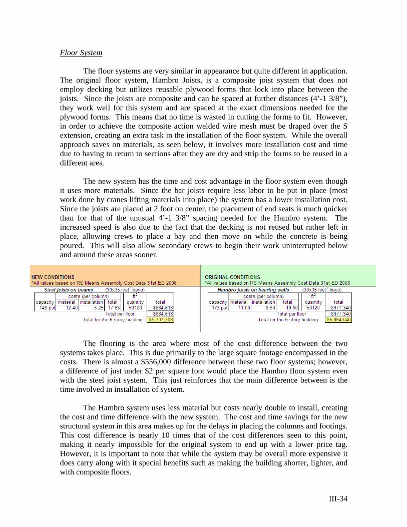
Floor System The floor systems are very similar in appearance but quite different in application.
The original floor system, Hambro Joists, is a composite joist system that does not employ decking but utilizes reusable plywood forms that lock into place between the joists. Since the joists are composite and can be spaced at further distances (4’-1 3/8”), they work well for this system and are spaced at the exact dimensions needed for the plywood forms. This means that no time is wasted in cutting the forms to fit. However, in order to achieve the composite action welded wire mesh must be draped over the S extension, creating an extra task in the installation of the floor system. While the overall approach saves on materials, as seen below, it involves more installation cost and time due to having to return to sections after they are dry and strip the forms to be reused in a different area.
The new system has the time and cost advantage in the floor system even though
it uses more materials. Since the bar joists require less labor to be put in place (most work done by cranes lifting materials into place) the system has a lower installation cost. Since the joists are placed at 2 foot on center, the placement of end seats is much quicker than for that of the unusual 4’-1 3/8” spacing needed for the Hambro system. The increased speed is also due to the fact that the decking is not reused but rather left in place, allowing crews to place a bay and then move on while the concrete is being poured. This will also allow secondary crews to begin their work uninterrupted below and around these areas sooner.
The flooring is the area where most of the cost difference between the two
systems takes place. This is due primarily to the large square footage encompassed in the costs. There is almost a $556,000 difference between these two floor systems; however, a difference of just under $2 per square foot would place the Hambro floor system even with the steel joist system. This just reinforces that the main difference between is the time involved in installation of system.
The Hambro system uses less material but costs nearly double to install, creating
the cost and time difference with the new system. The cost and time savings for the new structural system in this area makes up for the delays in placing the columns and footings. This cost difference is nearly 10 times that of the cost differences seen to this point, making it nearly impossible for the original system to end up with a lower price tag. However, it is important to note that while the system may be overall more expensive it does carry along with it special benefits such as making the building shorter, lighter, and with composite floors.
III-34

III-35
Wall System The last system that changed with the new design was the wall systems. The
original design had tube steel continuously capping the light gage bearing walls for load distribution purposes. This detail required field welding in order to attach the tube steel, and required careful attention to detail at corner locations. If the walls could be shop fabricated, it would require a crane or a large workforce to be able to tilt these walls into place and attach to the floor.
In the new structural system, the light gage walls are non-bearing and only need to
be continuously capped by a light gage cap. This makes the wall system lighter and easier to field fabricate; furthermore, it since the structure is not dependant on its erection, it can be constructed at any point in the building sequence. These walls can be built and tilted into place with far fewer workers and much less time. This can be seen below in the cost difference of nearly $171,000 between the new system and original system.
Conclusion
The bar joist structure bearing on a wide flange structure shows a $635,900 savings over the original Hambro on light gage bearing wall structure. In addition to the cost savings, there is also increased flexibility in the building sequencing such as allowing secondary crews to have access to an area quicker, not waiting on stripping formwork for reuse, and the fact that the structural progress is not dependant on the assembly of detailed light gage shear walls and tube steel. More exact savings calculations could be done in the future on a per item basis to determine exact time and cost benefits, but the results should be similar to those found in this report. In conclusion, the new design is the better construction management option based on the assemblies’ level of analysis, but this benefit must be weighed against the structural benefits of the original system.
Cladding Analysis Breadth Topic
EIFS Background
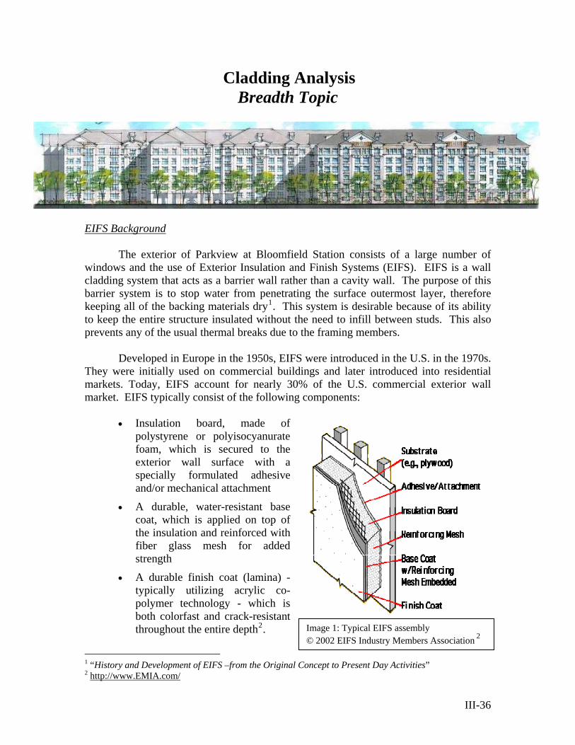
The exterior of Parkview at Bloomfield Station consists of a large number of windows and the use of Exterior Insulation and Finish Systems (EIFS). EIFS is a wall cladding system that acts as a barrier wall rather than a cavity wall. The purpose of this barrier system is to stop water from penetrating the surface outermost layer, therefore keeping all of the backing materials dry1. This system is desirable because of its ability to keep the entire structure insulated without the need to infill between studs. This also prevents any of the usual thermal breaks due to the framing members.
Developed in Europe in the 1950s, EIFS were introduced in the U.S. in the 1970s.
They were initially used on commercial buildings and later introduced into residential markets. Today, EIFS account for nearly 30% of the U.S. commercial exterior wall market. EIFS typically consist of the following components:
• Insulation board, made of
polystyrene or polyisocyanurate foam, which is secured to the exterior wall surface with a specially formulated adhesive and/or mechanical attachment
• A durable, water-resistant base coat, which is applied on top of the insulation and reinforced with fiber glass mesh for added strength
Image 1: Typical EIFS assembly © 2002 EIFS Industry Members Association
2
• A durable finish coat (lamina) - typically utilizing acrylic co-polymer technology - which is both colorfast and crack-resistant throughout the entire depth2.
1 “History and Development of EIFS –from the Original Concept to Present Day Activities” 2 http://www.EMIA.com/
III-36
Benefits
EIFS provides superior energy efficiency and offers much greater design
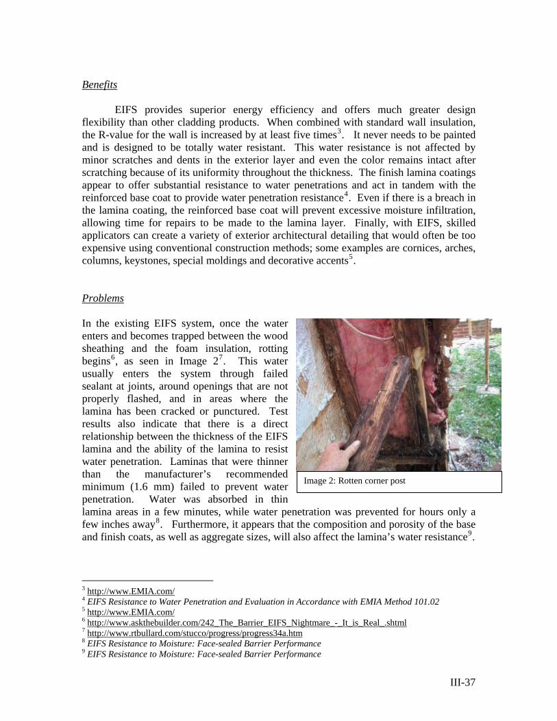
flexibility than other cladding products. When combined with standard wall insulation, the R-value for the wall is increased by at least five times3. It never needs to be painted and is designed to be totally water resistant. This water resistance is not affected by minor scratches and dents in the exterior layer and even the color remains intact after scratching because of its uniformity throughout the thickness. The finish lamina coatings appear to offer substantial resistance to water penetrations and act in tandem with the reinforced base coat to provide water penetration resistance4. Even if there is a breach in the lamina coating, the reinforced base coat will prevent excessive moisture infiltration, allowing time for repairs to be made to the lamina layer. Finally, with EIFS, skilled applicators can create a variety of exterior architectural detailing that would often be too expensive using conventional construction methods; some examples are cornices, arches, columns, keystones, special moldings and decorative accents5. Problems In the existing EIFS system, once the water enters and becomes trapped between the wood sheathing and the foam insulation, rotting begins6, as seen in Image 27. This water usually enters the system through failed sealant at joints, around openings that are not properly flashed, and in areas where the lamina has been cracked or punctured. Test results also indicate that there is a direct relationship between the thickness of the EIFS lamina and the ability of the lamina to resist water penetration. Laminas that were thinner than the manufacturer’s recommended minimum (1.6 mm) failed to prevent water penetration. Water was absorbed in thin lamina areas in a few minutes, while water penetration was prevented for hours only a few inches away8. Furthermore, it appears that the composition and porosity of the base and finish coats, as well as aggregate sizes, will also affect the lamina’s water resistance9.
Image 2: Rotten corner post
3 http://www.EMIA.com/4 EIFS Resistance to Water Penetration and Evaluation in Accordance with EMIA Method 101.02 5 http://www.EMIA.com/6 http://www.askthebuilder.com/242_The_Barrier_EIFS_Nightmare_-_It_is_Real_.shtml7 http://www.rtbullard.com/stucco/progress/progress34a.htm 8 EIFS Resistance to Moisture: Face-sealed Barrier Performance 9 EIFS Resistance to Moisture: Face-sealed Barrier Performance
III-37
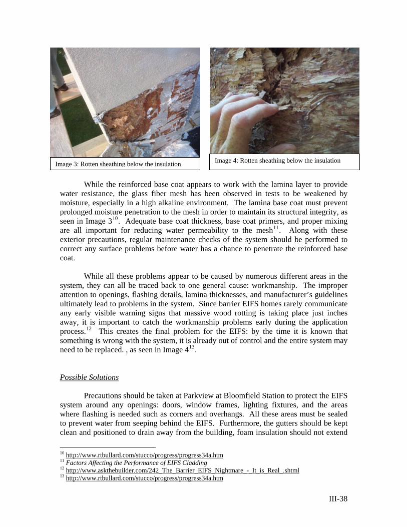
Image 4: Rotten sheathing below the insulation
While the reinforced base coat appears to work with the lamina layer to provide
water resistance, the glass fiber mesh has been observed in tests to be weakened by moisture, especially in a high alkaline environment. The lamina base coat must prevent prolonged moisture penetration to the mesh in order to maintain its structural integrity, as seen in Image 310. Adequate base coat thickness, base coat primers, and proper mixing are all important for reducing water permeability to the mesh11. Along with these exterior precautions, regular maintenance checks of the system should be performed to correct any surface problems before water has a chance to penetrate the reinforced base coat.
While all these problems appear to be caused by numerous different areas in the
system, they can all be traced back to one general cause: workmanship. The improper attention to openings, flashing details, lamina thicknesses, and manufacturer’s guidelines ultimately lead to problems in the system. Since barrier EIFS homes rarely communicate any early visible warning signs that massive wood rotting is taking place just inches away, it is important to catch the workmanship problems early during the application process.12 This creates the final problem for the EIFS: by the time it is known that something is wrong with the system, it is already out of control and the entire system may need to be replaced. , as seen in Image 413. Possible Solutions
Precautions should be taken at Parkview at Bloomfield Station to protect the EIFS system around any openings: doors, window frames, lighting fixtures, and the areas where flashing is needed such as corners and overhangs. All these areas must be sealed to prevent water from seeping behind the EIFS. Furthermore, the gutters should be kept clean and positioned to drain away from the building, foam insulation should not extend
10 http://www.rtbullard.com/stucco/progress/progress34a.htm11 Factors Affecting the Performance of EIFS Cladding 12 http://www.askthebuilder.com/242_The_Barrier_EIFS_Nightmare_-_It_is_Real_.shtml13 http://www.rtbullard.com/stucco/progress/progress34a.htm
Image 3: Rotten sheathing below the insulation
III-38

below grade, and any items that penetrate the lamina must be properly sealed14. There are also newer means of removing the water when it does penetrate the system. Drainable EIFS are now commonly a viable option and allows for drainage of the system, as seen in Image 515.
However, the main influence on the
effectiveness of the EIFS is the workmanship, both in the field and in the design office. In the field quality control needs to be better supervised by trained professionals and attention to detail is critical. More stringent requirements should also be used for the design of unique conditions such as overhangs, changes in wall height, corners, deck projections, and openings where minimum lamina thickness values don’t adequately protect against failure. In these areas specialized detailing and/or more accurate thicknesses could be derived based on available weather data16.
Image 5: Drainable EIFS
Further weather considerations should be
taken into account for Parkview at Bloomfield Station due to the unusual shape of the building. The stepped wall, as shown in image 6, will create circulating wind conditions that could cause water to be forced upwards towards the wall cladding. This necessitates that the top and bottom joints in these areas are designed for this condition. In addition to the extra protection needed at the top and bottom of the walls, efforts need to be taken to ensure that the decks do not allow any water to penetrate behind the lamina layer of the system. A drip edge on the decks and proper wall flashing details where the deck meets the EFIS wall should be adequate to prevent this problem.
Image 6: South-East wing
Finally, the orientation of the building must be taken into account in the EIFS
design. Due to the fact that the southern side of the building will be warmed by the sun’s rays, any water that may be covering the EIFS surface will be evaporated before it gets a chance to penetrate the lamina. Since this is not the case on the northern side of the building, thicker laminas should be used on this side in order to obtain better water penetration prevention characteristics. Thicker laminas should also be employed in areas where water may exist for longer portions of time such as around decks and other projections through the cladding system.
14http://homebuying.about.com/cs/syntheticstucco/a/eifs_facts.htm15 http://www.civil.uwaterloo.ca/BEG/Drawings/Enclosure_Drawings.htm 16 EIFS Resistance to Water Penetration and Evaluation in Accordance with EMIA Method 101.02
III-39
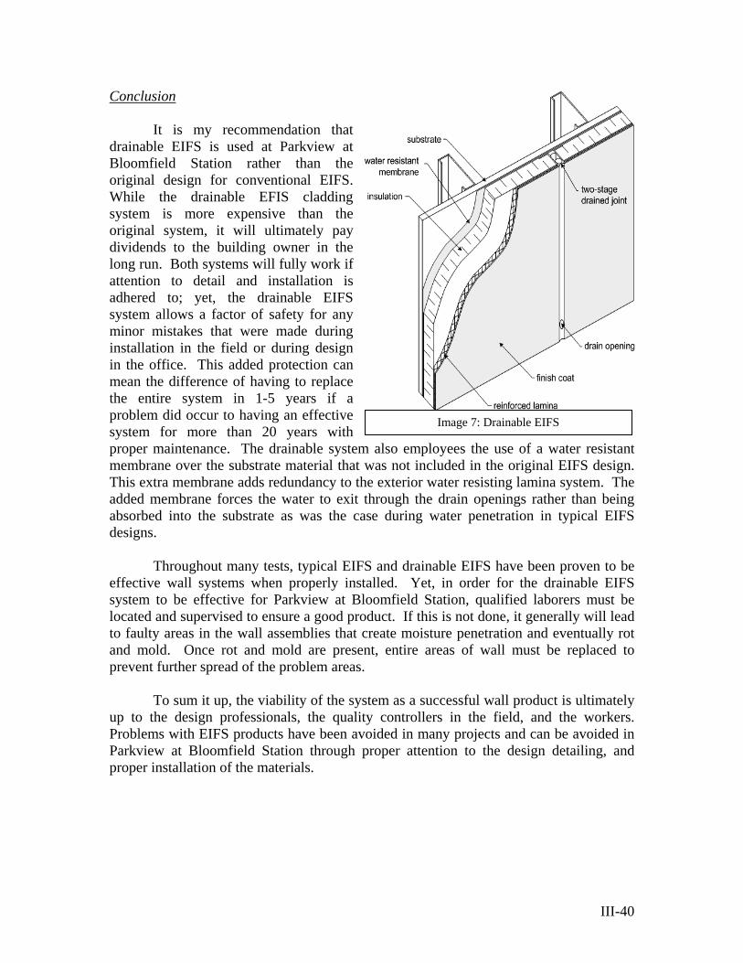
Conclusion
Image 7: Drainable EIFS
It is my recommendation that drainable EIFS is used at Parkview at Bloomfield Station rather than the original design for conventional EIFS. While the drainable EFIS cladding system is more expensive than the original system, it will ultimately pay dividends to the building owner in the long run. Both systems will fully work if attention to detail and installation is adhered to; yet, the drainable EIFS system allows a factor of safety for any minor mistakes that were made during installation in the field or during design in the office. This added protection can mean the difference of having to replace the entire system in 1-5 years if a problem did occur to having an effective system for more than 20 years with proper maintenance. The drainable system also employees the use of a water resistant membrane over the substrate material that was not included in the original EIFS design. This extra membrane adds redundancy to the exterior water resisting lamina system. The added membrane forces the water to exit through the drain openings rather than being absorbed into the substrate as was the case during water penetration in typical EIFS designs.
Throughout many tests, typical EIFS and drainable EIFS have been proven to be
effective wall systems when properly installed. Yet, in order for the drainable EIFS system to be effective for Parkview at Bloomfield Station, qualified laborers must be located and supervised to ensure a good product. If this is not done, it generally will lead to faulty areas in the wall assemblies that create moisture penetration and eventually rot and mold. Once rot and mold are present, entire areas of wall must be replaced to prevent further spread of the problem areas.
To sum it up, the viability of the system as a successful wall product is ultimately
up to the design professionals, the quality controllers in the field, and the workers. Problems with EIFS products have been avoided in many projects and can be avoided in Parkview at Bloomfield Station through proper attention to the design detailing, and proper installation of the materials.
III-40

Robert S. Whitaker
Senior in Architectural Engineering Structural Option
MAE/ BAE Pennsylvania State University
Senior Thesis Project:
Parkview at Bloomfield Station Spring 2006
Section IV
Conclusion
Faculty Consultant: Professor Parfitt
V-41I
This thesis presented and proved the process taken to create a new design for
Parkview at Bloomfield Station, a residential building located in Bloomfield, New Jersey. The original design criteria was introduced and played an important role in how the new design was laid out. From these design criteria, the new structural system was created and analyzed based on meeting and exceeding the structural and architectural requirements. Finally, the two breadth topics that were introduced to determine the new buildings cost advantage and cladding showed that compared to the original design there were advantages in both designs.
The original structural system, composed of light gage roof trusses, panelized
bearing light gage walls, 16" deep D500 Hambro® floor joists, and 38 shear walls in the main lateral force resisting system, was the more complex of the two building systems. Yet, with this complexity came the benefit of a composite floor system, less weight, and more redundancy throughout the building.
The analysis of the new steel braced frame design also showed benefits that were
not part of the original design. One such benefit is that the overall system is less complex and has a structure that can progress rapidly. This design also created a skeleton that can allow the change of uses at a later point more readily than the original design.
This design process also showed that using the most recent codes in the design
analysis did not have a tremendous difference on the overall result because only minor changes occurred between ASCE7-02 and ASCE7-05. Furthermore, from the two different framing orientations analyzed, the 20K9 bar joist floor system spanning 38'-0" was concluded to be the most efficient and compatible design, but it encountered slight problems with vibrations. A vibration analysis on the bar joist system shows that the floor is over the design limits but can still be considered acceptable.
Furthermore, the use of the braced frame system requires less lateral frames than
the original system making it less redundant, but creating gravity frames at some unit separation locations allowed for more savings and architectural advantages. This helps to preserve the architecture of the living units while allowing for quicker structural assembly. The foundation system in the new design, composed of spread footings that replace the original strip footings, was more expensive but had the same amount of material. This concentration of material helped out the lateral frames by providing greater downward force to resist the overturning moment and uplift. In addition to these structural issues, the new structural design was able to support the architectural features of the building. This is most evident at the drive aisles where the bracing patterns needed to mimic the decorative arches.
While the precast garage at the center of the building is structurally separate and
did not have much impact on the building design, it did show what a building separation of 4" made an effective building separation distance.
VI -42
The breadth topics were the final issues to be dealt with in the structure. In these sections two topics that effected large portions of Parkview at Bloomfield Station were investigated. In the first topic section, it was seen that the effect of changing from the original system to the system had nearly a half-million dollar cost advantage and that the sequencing schedule was more flexible than the original system. It also made note that the original system had structural benefits that did not have a price tag but were important nonetheless.
In the second topic section, the current Exterior Insulation and Finish System
(EIFS) were studied for its benefits and shortfalls. After learning about past mistakes made with the system, it was shown that the most important factor in getting an EIFS to function properly was the quality of workmanship put into the project. With this in mind, the recommendations for adequate and complete details along with proper supervision were advised. In addition, a method to compensate for any error in the design or supervision is to use a drainable EIFS. Even though this system is more expensive, it is the best solution to guarantee a proper building envelope and is used in the new design of the building.
Throughout the design comparison between the new design and the old design,
there have been many benefits and disadvantages shown for both systems, but in the end both are equally viable solutions to the same problem
V-43I
Robert S. Whitaker
Senior in Architectural Engineering Structural Option
MAE/ BAE Pennsylvania State University
Senior Thesis Project:
Parkview at Bloomfield Station Spring 2006
Section V
Appendices
Faculty Consultant: Professor Parfitt
V-44

Robert S. Whitaker
Senior in Architectural Engineering Structural Option
MAE/ BAE Pennsylvania State University
Senior Thesis Project:
Parkview at Bloomfield Station Spring 2006
Section V
Building Summary
Faculty Consultant: Professor Parfitt
V-45
General Building Statistics:
Building Name: Parkview at Bloomfield Station Location and Site: Washington St, Bloomfield Township, NJ 07003 Building Occupant Name: Toll Brothers, Inc. Occupancy or Function Types:
Primary Occupancy: Condominiums (use group R-2) Accessory Occupancy: Pre cast parking garage (use group S-2)
Code: IBC 2000 NJ (no structural changes noted in the NJ version) Fair housing Act
Zoning: Residential (There are no special or historical issues for the building) Size:
Total Sq. Ft.: 453,473 ft^2 Building: 300,725 ft^2 Pre cast Garage: 152,748 ft^2
Number of Stories Above Grade: 6 stories Project Team:
Owner: Toll Brothers, Inc. www.tollbrothers.com
Forest City Residential Group www.fceinc.com
Architect: Minno and Wasko www.minnowasko.com
Structural Engineer: Cates Engineering www.cateseng.com
Pre cast Engineer: Unistress Corporation www.unistresscorp.com
Civil Engineer: PMK Group www.pmkgroup.com
MEP Engineer: R.W. Sullivan, Inc. www.rwsullivan.com
Contractor/ CM: Bovis - lend lease www.bovislendlease.com
Dates of Construction: Project Startup: March 27, 2005 Design Development: July 29, 2005 Final Specs: August 5, 2005 Permit Set: October 12, 2005 Planned construction start: November 10, 2005
Cost: Overall Project: $65,616,081 Building: $56,936,063 Pre cast Garage: $8,680,018
Project delivery method: Qualified Design-bid-build (to be determined exactly)
V-46

Building System Information: Architecture:
Parkview at Bloomfield Station is a unique 6 story residential condominium building located in Bloomfield Township, NJ. The building’s footprint is irregular and wraps around a pre-cast parking garage. The building is nestled between Toney’s Brook, Washington St, and a train station for the Midtown Line. There are 197 condominium units and 330 parking spaces included in the design of this building. There is an exercise room located above the lobby area for residential use. There is a drop off circle in the front of the building and a outdoor gazebo and portico area for resident enjoyment.
Building Envelope:
The roof system consists of asphalt shingle roofing over metal deck and fire rated plywood. The light gage roof trusses have either a 12:12 slope or 8:12 slope for gable
roofs, with portions in the middle acting as a flat roof. Standing seam copper roof is used in some areas. The main body of the roof consists of hip roof conditions accented with gable roof sections over balcony areas. The exterior wall cladding is an Exterior Finish and Insulation System (EFIS) over light gage walls. Anderson vinyl windows and entry doors also make up parts of the wall system. The wall along the train line consists mainly of the open pre cast garage panels. The building is separated from the pre cast garage by an air gap and expansion joint. The
building foundation is a 2’-6” wide continuous footings with 3’-0” column spread footings. The pre-cast garage has an extensive pile foundation consisting of 29 pile groups; each consisting of (5) 50’ long “H” steel piles of 100 ton capacity each. There are 10” retaining walls on the site also, each with a footing of at least 2’-6” wide.
Exterior Finish & Insulation System
Structural:
The structural system for Parkview @ Bloomfield Station is a Hambro® and bearing panelized light gage wall system. The typical exterior bearing wall consists of a 6” light gage wall, while the typical interior bearing wall consists of a 4” light gage wall. All 6 floors have the same floor plans with the exception of 4 locations: an entry/ lobby unit, a 2 story drive aisle, a 1 story drive aisle, and at a 1st floor exit route. The typical floor system is a 16” deep joist Hambro composite floor system with 3” slabs (3000 psi conc.). The ground level floor is composed of a 4” slab on grade system. The Hambro system is supported on either wide flange beams or tube steel distribution plates located on the light gage bearing walls. The typical beam is
V-47
W10x12, HSS 4x4x5/16”, or HSS 6x4x5/16”. Column sizes range from HSS 3x3x1/4” to HSS 7x3x3/8”. The foundation system of Parkview is continuous footings, spread footings, and piles. The Garage is on 100 ton H piles. The piles are drilled to bedrock (ranging from 42-53 ft). The Garage consists of double T shapes attached to pre cast verticals. The lateral force resisting frame consists of strapped light gage shear walls and cross bracing system over drive aisles. Interior walls are panelized non-bearing light gage infill walls. The roof consists of light gage roof trusses at 48” oc, and includes girder trusses to accommodate end hip conditions.
Construction: Site work includes existing building demolition, grading, importing fill and locating new utilities. It will also include installation of fountains, gazebo and a portico. The construction of the parking garage will be completed first, using a crane to lift the pre cast double T shapes into place. Upon completion of the parking garage the panelized light gage walls will be lifted into place and anchored into the Hambro floor system. The delivery method is a qualified design-bid-build for both the building and the parking garage. The total cost of completing the building is $65,616,081, and that does not include a CM bond.
Electrical: Panels are sized at 125A 1P3W, and there are 2 building transformers. Secondary service includes feeders in GRC conduit from the utility company transformers to the (2) 3000 amp switchboards. Apartment services are fed from meter centers located on each floor at 2 locations, with 125 amp feeders to each apartment load center with 3C#1 armored interlock cables. The emergency generator is a 250 KW 120/208, diesel fired with an 800 amp ATS. The HVAC equipment in the units is based on (1) 20/3p fed to the HWH/HVAC unit an electric range and dryer, each with 50/2P feeds. Each unit is accessed with (1) ¾” conduit from the tele/com closet and (1) 1” pull wire conduit for CATV requirements. The electrical system includes the incoming duct banks for electrical/CATV/Tele utilities, all to be concrete encased with pull wires. Also included is the fit out of building and garage area with lighting, HVAC, FA, telephone and CATV.
Lighting:
There is lighting located exteriorly at the fountain, gazebo, and portico. In addition, site lighting includes pole fixtures, and the access point of the existing (2) 5” PVC utility line. Interior lighting consists of MC cabling and EMT within garage areas. Temporary lighting and power is included.
Mechanical:
The HVAC includes sheet metal ducts covered in 1 ½” insulation, insulation board on the exterior walls, unit temperature controls, refrigerant piping, water heaters, condensate drain piping, grd’s testing and balancing, and rigging. Electric base board, air handling units, gas fired furnaces and air cooled condensing units compose the HVAC system. There is a refrigerant loop between air handling units and
V-48

condensing units. Hot water from hot water heaters is sent to air handling units for use in heating air. The exhaust fan is Nutone LS80 ( no lights). I will be getting more information in this area.
Fire Protection:
The fire protection system includes a fire pump, wet sprinkler system and a dry sprinkler system in the attic area. The garage will have a dry sprinkler system. The wet fire protection system is connected to a 6” combination water main, installed with a 1,500 GPM fire pump and jockey pump. There is a fire department connection on the west side of the building to the fire protection room. The dry systems in the attic and garage are on a connected system and branched from this room. The dry system will be installed with galvanized steel pipe. The floor mains and branches will be orange CPVC with sprinkler heads concealed in the plaster ceiling.
Plumbing:
The building includes sanitary system, natural gas, domestic water with booster pump, plumbing fixtures, gas hot water heaters, washing machine indirect waste and water heater indirect waste. The main utility room is located outside the 2nd floor trash room. The garage includes storm water and oily water drains, non freeze wall hydrants connect to condo building and domestic water. The sanitary system is composed of schedule 40 PVC pipe and drainage fittings. The natural gas system is based on a load of 70 CFH per hot water heater. It is supplied from a 10” line from the source and branches off into schedule 40 black steel pipes varying in size from 8” to 3” with 2” valve taps for single risers. Domestic water is brought in through a 6” pipe with water meter and backflow preventer. Once inside, it is split into (2) 4” mains for north and south halves. Main sizes vary from 4” down to 2” based on 14.5 WSFU per condo and velocity less than 8 FPS. A Triplex water booster pump is used to maintain the water pressure to upper floors. Plumbing fixtures are attached with type DWV copper piping. The hot water heater is a direct vent with 75 gallon storage and 100 GPH recovery.
Telecommunications:
Telephone and CATV outlets are provided for each living unit.
Transportation: There are (2) 6-stop 2,500lbs elevators and (1) 6-stops 3,500lbs elevator. There are also six stair wells that access to all 6 levels of the building, and access to all floors from the 6 story attached parking garage.
Special Systems:
There is a security system terminal at the main entrance, 14 additional locations have panel points, and there is (1) overhead electric security parking door at the garage.
V-49
Robert S. Whitaker
Senior in Architectural Engineering Structural Option
MAE/ BAE Pennsylvania State University
Senior Thesis Project:
Parkview at Bloomfield Station Spring 2006
Section V
Calculations, Figures, Tables, and Charts Index
Faculty Consultant: Professor Parfitt
V-50
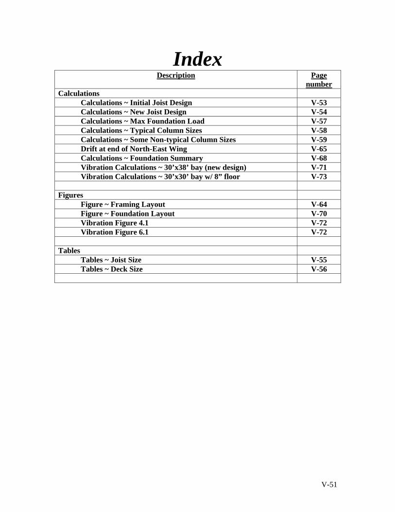
V-51
Index Description Page
number Calculations
Calculations ~ Initial Joist Design V-53 Calculations ~ New Joist Design V-54 Calculations ~ Max Foundation Load V-57 Calculations ~ Typical Column Sizes V-58 Calculations ~ Some Non-typical Column Sizes V-59 Drift at end of North-East Wing V-65 Calculations ~ Foundation Summary V-68 Vibration Calculations ~ 30’x38’ bay (new design) V-71 Vibration Calculations ~ 30’x30’ bay w/ 8” floor V-73
Figures
Figure ~ Framing Layout V-64 Figure ~ Foundation Layout V-70 Vibration Figure 4.1 V-72 Vibration Figure 6.1 V-72
Tables
Tables ~ Joist Size V-55 Tables ~ Deck Size V-56

Robert S. Whitaker
Senior in Architectural Engineering Structural Option
MAE/ BAE Pennsylvania State University
Senior Thesis Project:
Parkview at Bloomfield Station Spring 2006
Section V
Calculations Section
Faculty Consultant: Professor Parfitt
V-52

Initial Joist Design
V-53

New Joist Design
V-54

Joist Size
35
V-55

Deck Size
V-56
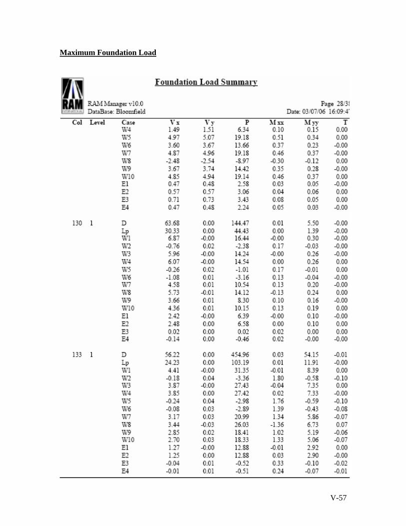
Maximum Foundation Load
V-57

Typical Column Sizes
V-58

Some Non-typical Column Sizes
V-59
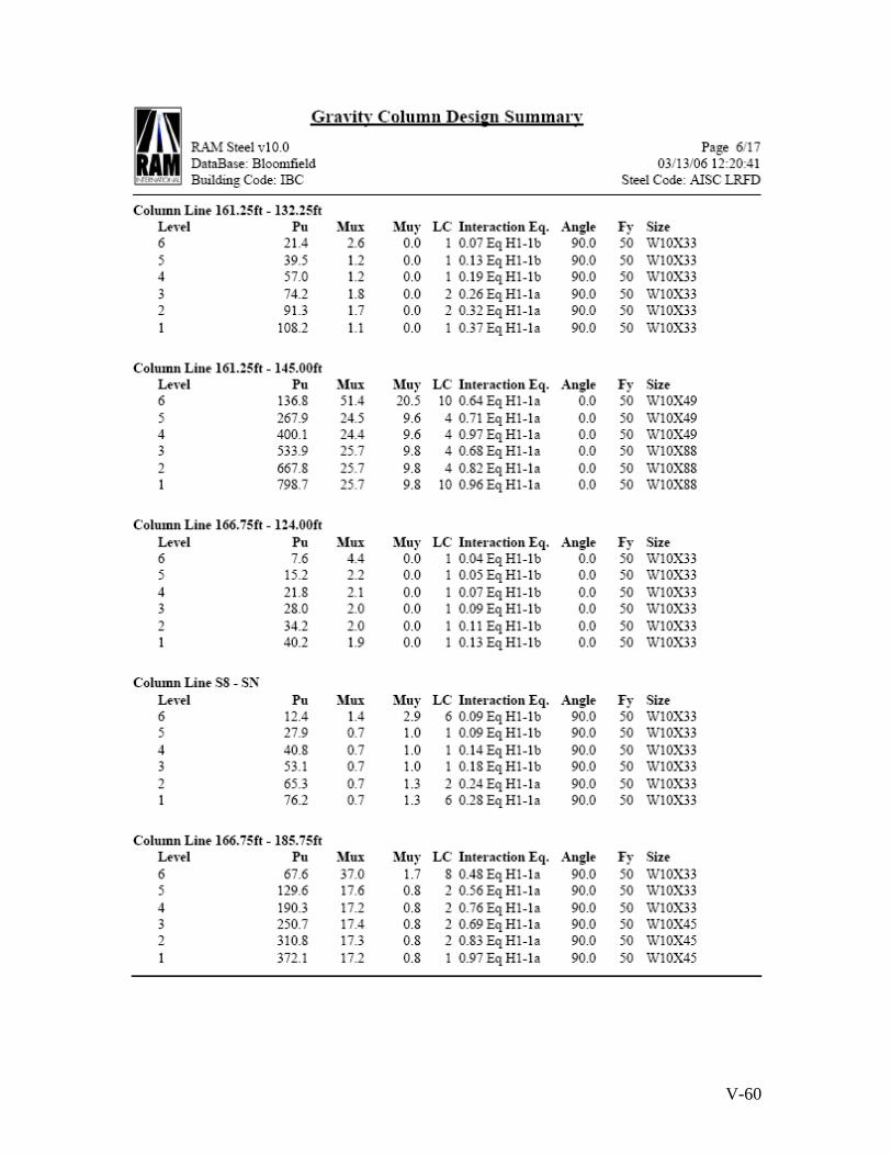
V-60
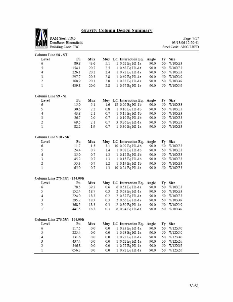
V-61

V-62
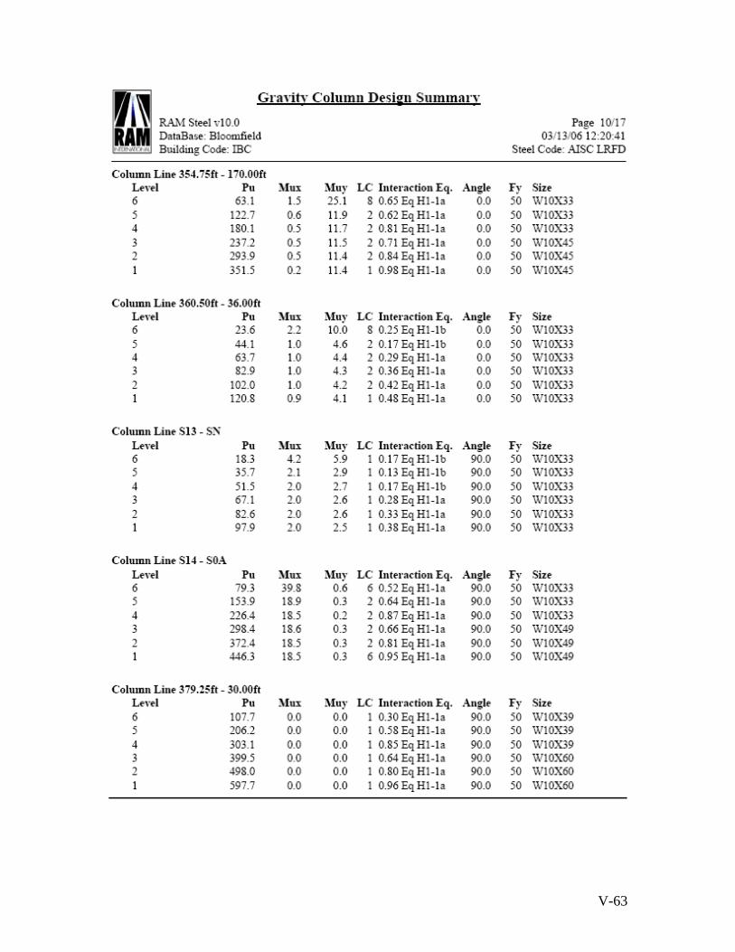
V-63

V-64
Framing Layout

V-65
Drift at end of North-East Wing

V-66
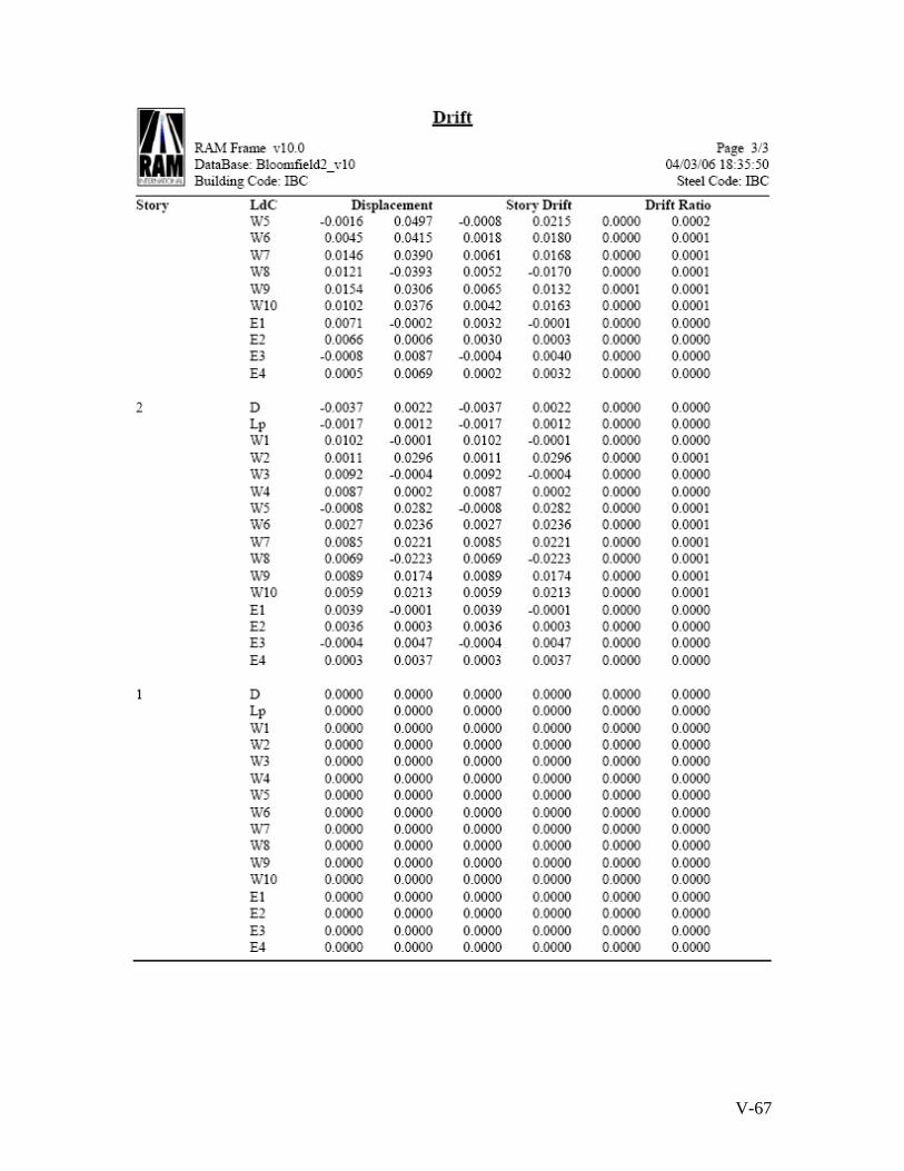
V-67
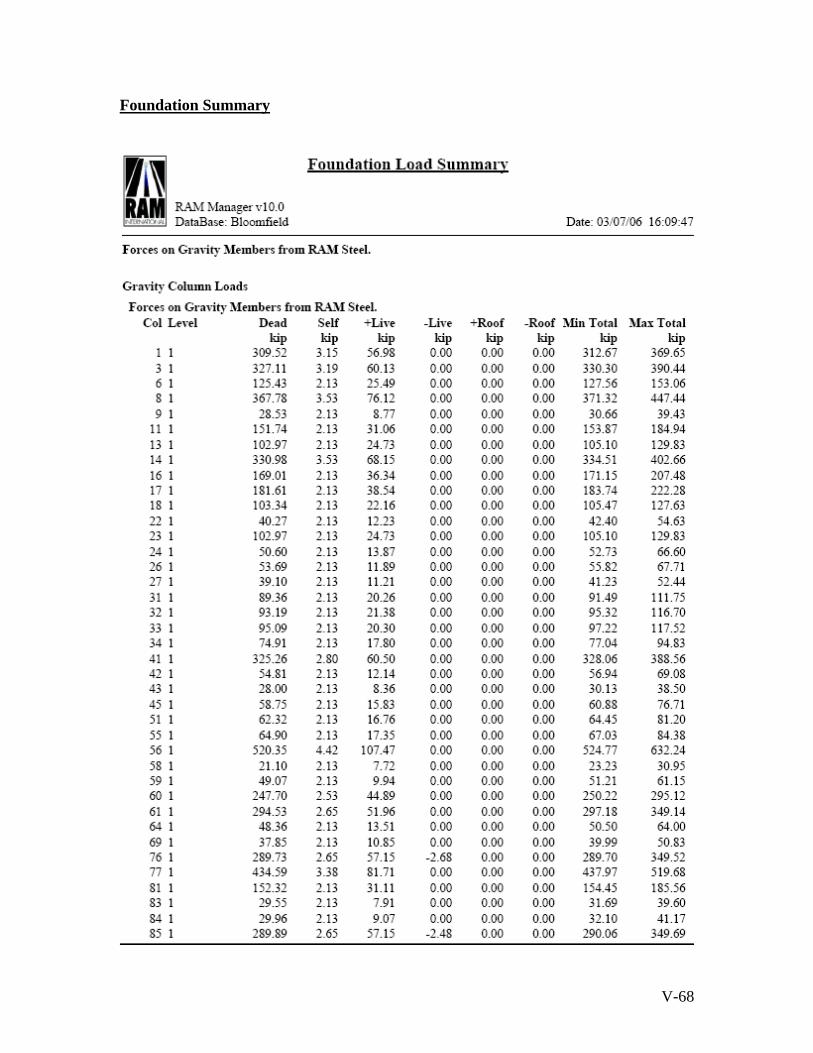
V-68
Foundation Summary

V-69

V-70
Foundation Layout
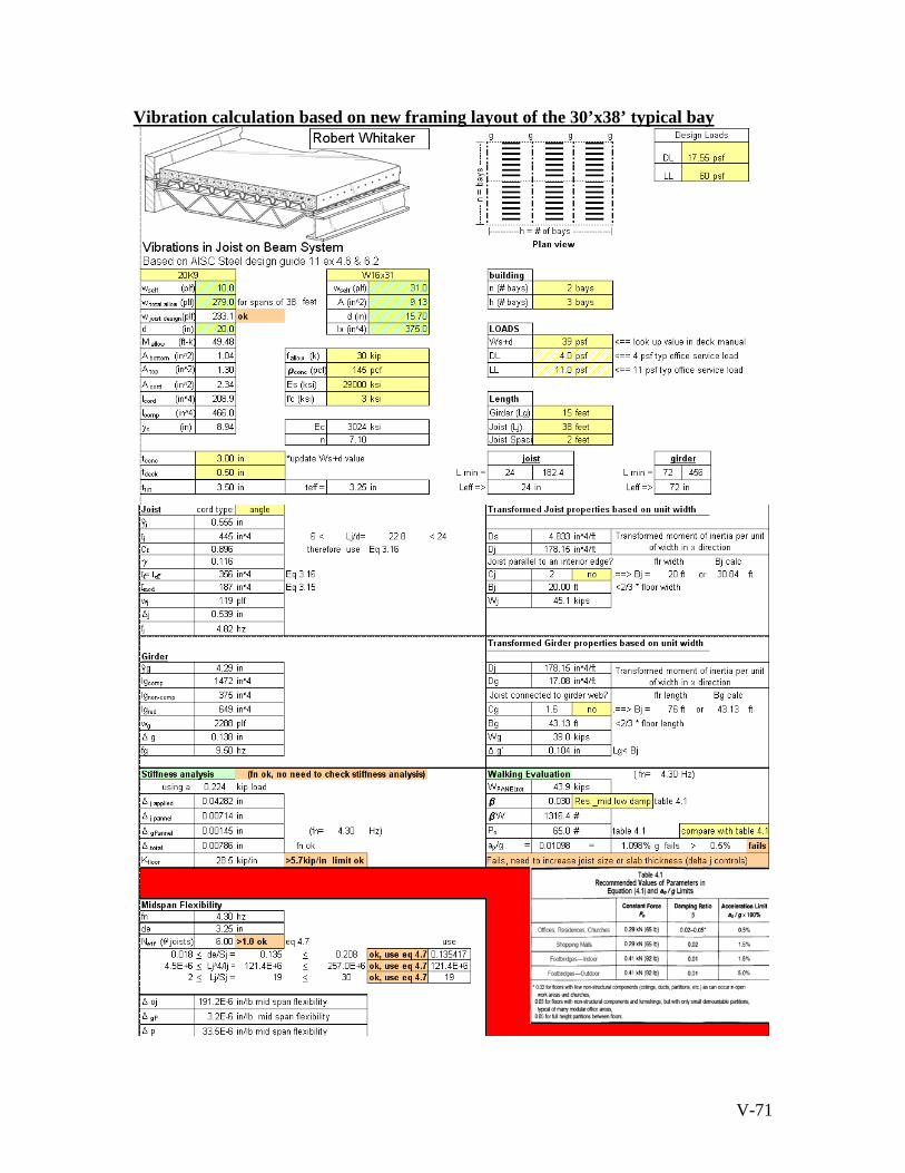
V-71
Vibration calculation based on new framing layout of the 30’x38’ typical bay

V-72

V-73
Vibration calculation based on new framing layout of the 30’x38’ typical bay
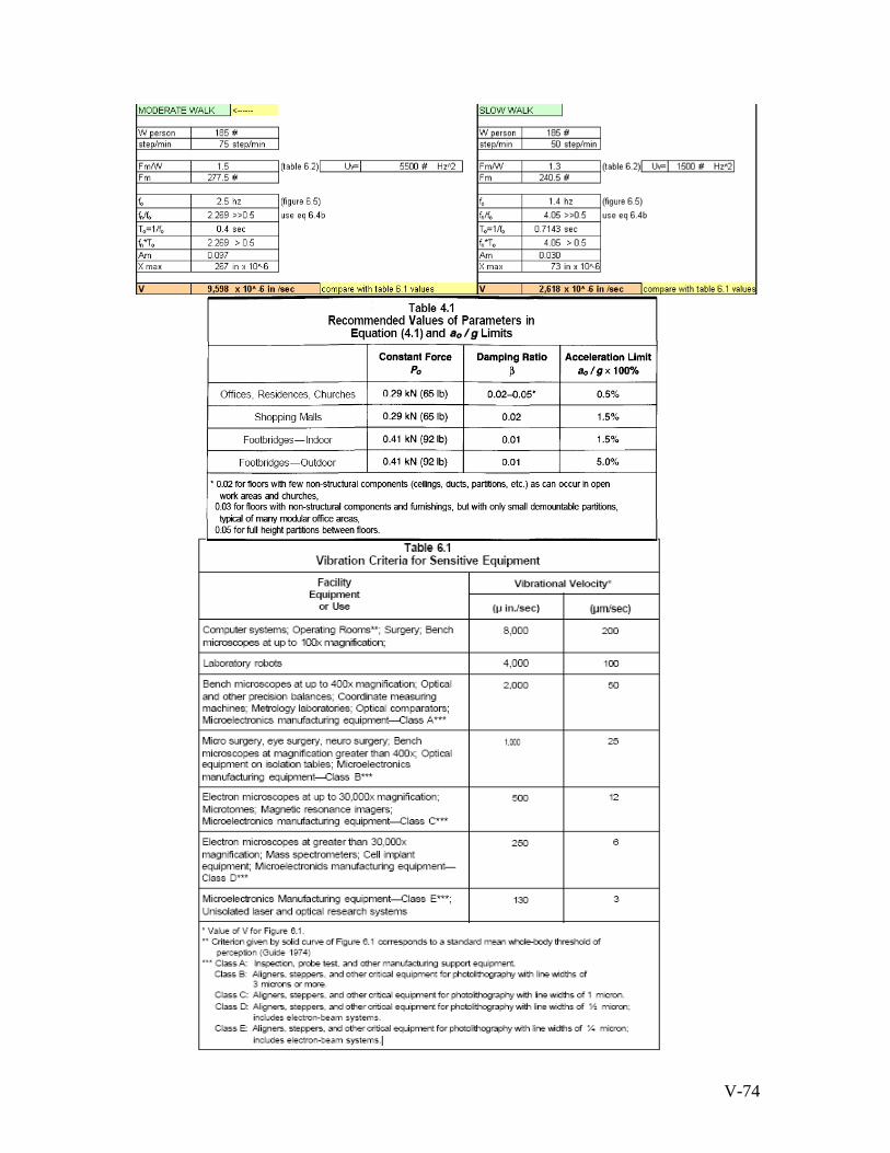
V-74
V-75
Robert S. Whitaker
Senior in Architectural Engineering Structural Option
MAE/ BAE Pennsylvania State University
Senior Thesis Project:
Parkview at Bloomfield Station Spring 2006
Section V
References and Bibliography
Faculty Consultant: Professor Parfitt

V-76
Bibliography ~ Existing Building Description American Institute of Steel Construction “Manual of Steel Construction ~ Allowable
Stress Design 2nd Edition” copyright 1997 American Society of Civil Engineers (ASCE) 7-02 “Minimum Design Loads for
Buildings and Other Structures” copyright 2003 International Building Code (IBC 2000) Bibliography ~ Structural Depth Analysis American Institute of Steel Construction “Manual of Steel Construction ~ Load and
Resistance Factor Design 3rd Edition” copyright 2001 American Society of Civil Engineers (ASCE) 7-05 “Minimum Design Loads for
Buildings and Other Structures” copyright 2006 International Building Code (IBC 2003) Bibliography ~ RAM Model RAM Structural System Program, Version 10 Bibliography ~ Vibrations American Institute of Steel Construction Steel Design Guide 11 “Floor Vibrations due to
Human Activity” copyright 2003 ex 4.6 & 6.2
New Columbia Joist Company “Steel Joists and Joist Girders” Nicholas J. Bouras, Inc. copyright 2002
Vulcraft “Steel Roof and Floor Deck” Nucor Corporation 1998 Bibliography ~ Cost Advantages RS Means Assembly Cost Data 31st ED 2006
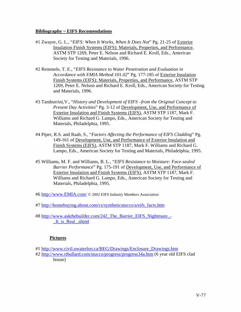
V-77
Bibliography ~ EIFS Recomendations #1 Zwayer, G. L., “EIFS: When It Works, When It Does Not” Pg. 21-25 of Exterior
Insulation Finish Systems (EIFS): Materials, Properties, and Performance, ASTM STP 1269, Peter E. Nelson and Richard E. Kroll, Eds., American Society for Testing and Materials, 1996.
#2 Remmele, T. E., “EIFS Resistance to Water Penetration and Evaluation in
Accordance with EMIA Method 101.02” Pg. 177-185 of Exterior Insulation Finish Systems (EIFS): Materials, Properties, and Performance, ASTM STP 1269, Peter E. Nelson and Richard E. Kroll, Eds., American Society for Testing and Materials, 1996.
#3 Tamburrini,V., “History and Development of EIFS –from the Original Concept to
Present Day Activities” Pg. 3-12 of Development, Use, and Performance of Exterior Insulation and Finish Systems (EIFS), ASTM STP 1187, Mark F. Williams and Richard G. Lampo, Eds., American Society for Testing and Materials, Philadelphia, 1995.
#4 Piper, R.S. and Raab, S., “Factors Affecting the Performance of EIFS Cladding” Pg.
149-161 of Development, Use, and Performance of Exterior Insulation and Finish Systems (EIFS), ASTM STP 1187, Mark F. Williams and Richard G. Lampo, Eds., American Society for Testing and Materials, Philadelphia, 1995.
#5 Williams, M. F. and Williams, B. L., “EIFS Resistance to Moisture: Face-sealed
Barrier Performance” Pg. 175-191 of Development, Use, and Performance of Exterior Insulation and Finish Systems (EIFS), ASTM STP 1187, Mark F. Williams and Richard G. Lampo, Eds., American Society for Testing and Materials, Philadelphia, 1995.
#6 http://www.EMIA.com/ © 2002 EIFS Industry Members Association #7 http://homebuying.about.com/cs/syntheticstucco/a/eifs_facts.htm #8 http://www.askthebuilder.com/242_The_Barrier_EIFS_Nightmare_-
_It_is_Real_.shtml
Pictures #1 http://www.civil.uwaterloo.ca/BEG/Drawings/Enclosure_Drawings.htm #2 http://www.rtbullard.com/stucco/progress/progress34a.htm (6 year old EIFS clad
house)