seminar report2
DESCRIPTION
original reportTRANSCRIPT
1 | P a g e
Chapter 1
INTRODUCTION
Nowadays, energy conservation and safety have become the main directions for
vehicle research and development. Within these measures of oil saving and emission
reduction, the weight reduction of vehicle itself has the most significant effect. So active
research is currently being devoted to the development of highly innovative designs involving
lightweight materials, such as high strength steel, aluminum or magnesium alloys, and
metallic or polymeric foams. To meet the demand of vehicle safety and weight reduction,
during the past decades, many research works have been carried out in energy absorption
characteristics of thin-walled structures, including empty thin-walled columns and foam-
filled thin-walled members.
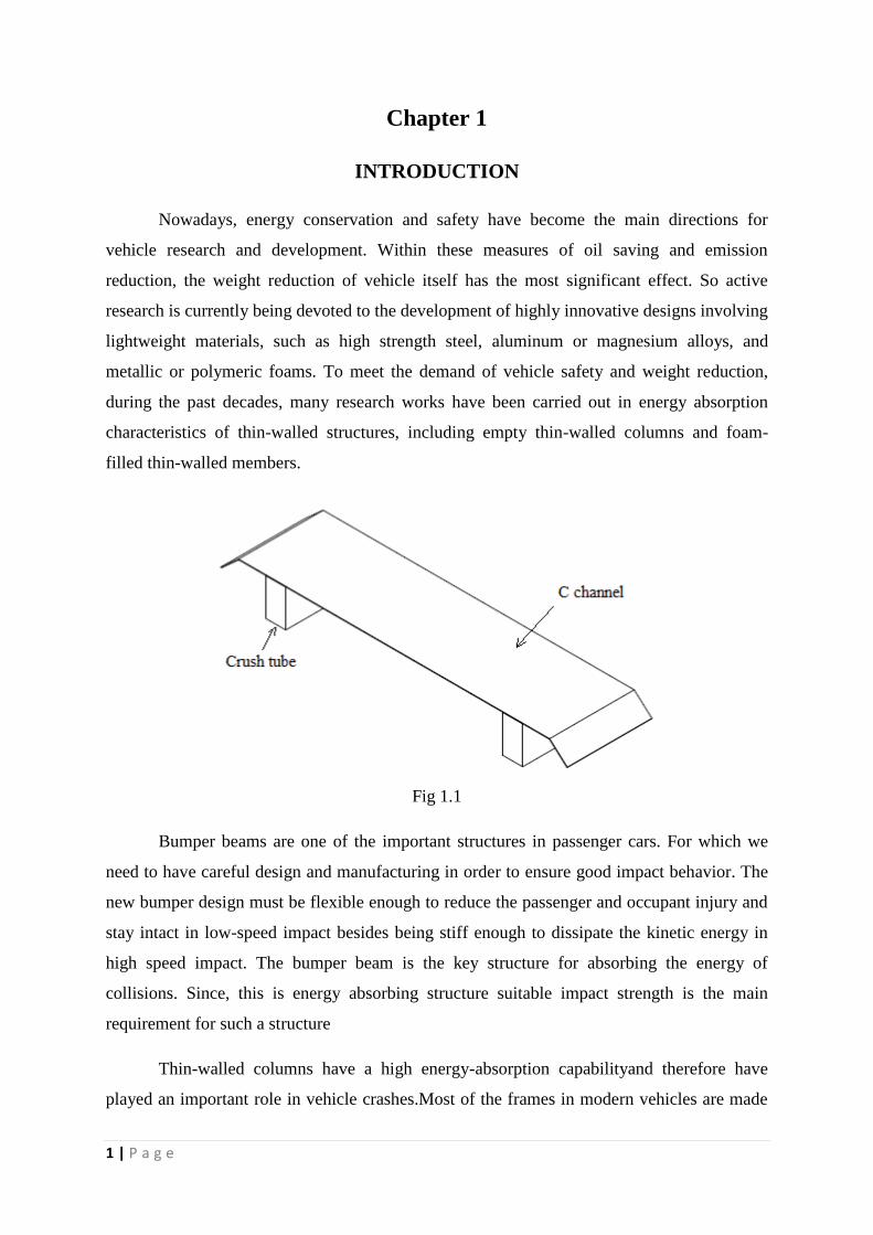
Fig 1.1
Bumper beams are one of the important structures in passenger cars. For which we
need to have careful design and manufacturing in order to ensure good impact behavior. The
new bumper design must be flexible enough to reduce the passenger and occupant injury and
stay intact in low-speed impact besides being stiff enough to dissipate the kinetic energy in
high speed impact. The bumper beam is the key structure for absorbing the energy of
collisions. Since, this is energy absorbing structure suitable impact strength is the main
requirement for such a structure
Thin-walled columns have a high energy-absorption capabilityand therefore have
played an important role in vehicle crashes.Most of the frames in modern vehicles are made
2 | P a g e
from thin-walledsections. Tubes absorb the impact energy through materialdeformation
during crushing. The collapse of a tube has twoprimary modes, axial and bending, but during
an actual crashevent, the tube is subjected to either pure axial or bendingcollapse, but rather a
combination of the two modes. If the tubeexperiences global bending instead of axial
crushing, the energyabsorption will be lower, and both moments and axial forceswill be
transferred to the rest of the structure
Crashworthiness studies devote a great deal of attention to thebehavior of thin-walled
structures, which have been widely usedas load bearing structures as well as energy absorbers
in engineeringpractices such as in automobile and aeronautical applications[1].The increasing
interest in safety and crashworthiness of structures has led to a comprehensive research on the
crashing responsesof thin-walled tubes with different cross sectiongeometries analytically
[2,3], numerically [4,5] and experimentally[6,7]. Optimization studies on thin-walled
structures for the crashworthinessdesign have also been carried out [8–10]. Studying
thecrashworthiness of thin-walled tubes subjected to bending is relativelynew, because to
date the investigations have mainly been focusedon the collapse of thin-walled circular tubes
under axialloading [11–14].
The crash box located between bumper and side rails protectspassengers and
expensive vehicle components by absorbing initialkinetic energy in a frontal vehicle crash
event by ensuring a lowplastic flow stress level on the auto-body frame
Energy absorbers are often part of the car structure to protect passengers and the
structure itself during impact. One type of energy absorber is the crash box, which is
connected to thebumpers, situated in the front and rear end of the body structure. The crash
box is designed absorb energy at low speed impacts. Its purpose is to control the initial
kinetic energy during impact, and at the same time avoid permanent deformations in the rest
of the car body by keeping the force levels sufficiently low. The absorption of energy is
controlled by the plastic work in thecrash box, which is given by the area below the
forcedisplacement curve.
3 | P a g e
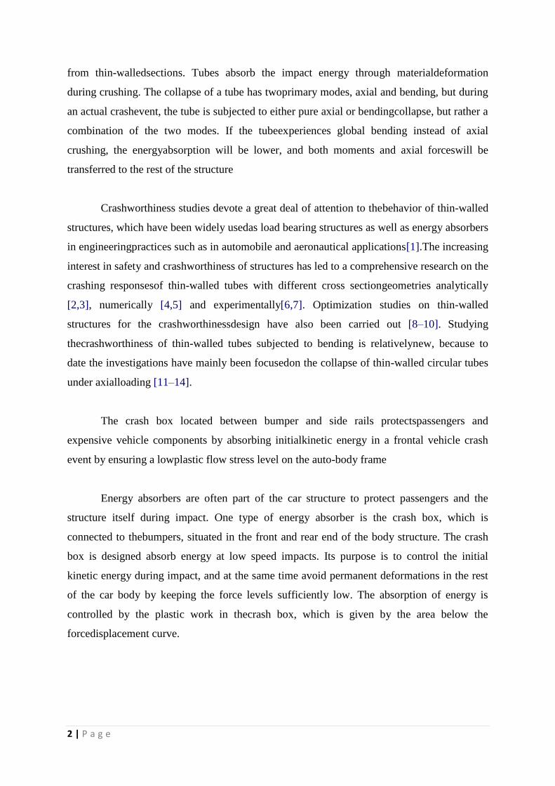
Fig 1.2 Bumper beam
Experienced automotive engineers design functional components in the context
oftheir surrounding elements. For example, a bumper should not be stronger than the
structure it isintended to protect. Likewise, the stiffness of the vehicle structure to which the
bumper is mounted contributes to the total elastic displacement of the bumper surfaces, and
hence to itsenergy absorption.
4 | P a g e
Chapter 2
LITERATURE REVIEW
The literature review of Energy absorbing is explained as follows. The author
JavadMarzbanrad, Mehdi Mehdikhanlo,AshkanSaeedi Pour, in their paper they have
simulated a theory about the axial crushing of steel and aluminiumtubes between 2
parallel plates subjected to impact dynamicaxial loading was investigated. A
nonlinear finite element model was developed and analyzed with LS-DYNA inthis
simulation. Verification was done through comparison with some experimental results
in a steel square tube. Good agreement was observed between the FEM force histories
with those obtained from experimental results. Typical deformation histories for 3
sectional types (square, circle, and ellipse) were studied and presented. Itwas
concluded that the elliptic tubes absorb more energy during collisions. The effects of
width and thicknesswere also investigated. It was concluded that the energy
absorption may be increased about 22% with widthenhancement of 66%, showing that
the energy absorption would be one third of the width increase. Relatedto thickness,
the amount of energy absorption will be more with increasing thickness for smaller
section tubes. Energy per weight absorption during the collision of 2 metals (steel and
aluminium) was also calculated andcompared. The results showed that the amount of
energy absorption per weight of steel tube was about 4.5times greater than the
aluminum tube for all 3 sections, square, circle and ellipse. However, the square
section and then the circular section of the steel tube absorbed energy per weight more
than the elliptic section of the aluminum tube, respectively [1].
The author A.AlaviNian,M. in their paper they have simulated a theory about
the mechanical behavior of thin-walled aluminum structures with triangular, square,
hexagonal and octagonal sections in simple and multi-cell forms was studied under
quasi- static compression. Samples were loaded using a Santam apparatus and
simulations were done using LS-DYNA code. There was good consistency between
the test data and simulation results. Experimental samples showed lower initial peak
load in comparison with simulations because on the type of connection therefore, their
crushing force efficiency was greater than for the simulated samples. A comparison of
the results showed that multi-cell sections had greater SAE in comparison with simple
sections, especially for triangular geometry. It was shown that the first type of multi-
5 | P a g e
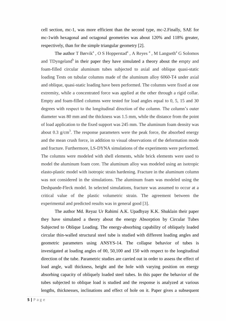
cell section, mc-1, was more efficient than the second type, mc-2.Finally, SAE for
mc-1with hexagonal and octagonal geometries was about 120% and 118% greater,
respectively, than for the simple triangular geometry [2].
The author T Børvika , O S Hopperstad
a , A Reyes
a , M Langseth
a G Solomos
and TDyngelandb
in their paper they have simulated a theory about the empty and
foam-filled circular aluminum tubes subjected to axial and oblique quasi-static
loading Tests on tubular columns made of the aluminum alloy 6060-T4 under axial
and oblique, quasi-static loading have been performed. The columns were fixed at one
extremity, while a concentrated force was applied at the other through a rigid collar.
Empty and foam-filled columns were tested for load angles equal to 0, 5, 15 and 30
degrees with respect to the longitudinal direction of the column. The column’s outer
diameter was 80 mm and the thickness was 1.5 mm, while the distance from the point
of load application to the fixed support was 245 mm. The aluminum foam density was
about 0.3 g/cm3. The response parameters were the peak force, the absorbed energy
and the mean crush force, in addition to visual observations of the deformation mode
and fracture. Furthermore, LS-DYNA simulations of the experiments were performed.
The columns were modeled with shell elements, while brick elements were used to
model the aluminum foam core. The aluminum alloy was modeled using an isotropic
elasto-plastic model with isotropic strain hardening. Fracture in the aluminum column
was not considered in the simulations. The aluminum foam was modeled using the
Deshpande-Fleck model. In selected simulations, fracture was assumed to occur at a
critical value of the plastic volumetric strain. The agreement between the
experimental and predicted results was in general good [3].
The author Md. Reyaz Ur Rahimí A.K. Upadhyay K.K. Shuklain their paper
they have simulated a theory about the energy Absorption by Circular Tubes
Subjected to Oblique Loading. The energy-absorbing capability of obliquely loaded
circular thin-walled structural steel tube is studied with different loading angles and
geometric parameters using ANSYS-14. The collapse behavior of tubes is
investigated at loading angles of 00, 50,100 and 150 with respect to the longitudinal
direction of the tube. Parametric studies are carried out in order to assess the effect of
load angle, wall thickness, height and the hole with varying position on energy
absorbing capacity of obliquely loaded steel tubes. In this paper the behavior of the
tubes subjected to oblique load is studied and the response is analyzed at various
lengths, thicknesses, inclinations and effect of hole on it. Paper gives a subsequent
6 | P a g e
steps has taken to see understand all the possible effects on tube when loaded
obliquely under certain defined conditions. Initially the tube length effect, thickness
and inclination effect has been observed, than the effect of hole as a buckling initiator
is also presented and finally the best position of the hole to get the higher energy
absorbing capacity is concluded [4].
The author Yong Zhang, Guangyong Sun, Guangyao Li , Zhen Luo , Qing Li
in their paper they have explored a theory about the crashworthiness design for a
special thin-walled structure made of foam-filled squared bi-tubal columns. The
design criteria of specific energy absorption (SEA), peak impact force (Fmax) and
utilization rate (UR) of progressive deformation length were taken into account under
dynamic crushing loading. The Kriging modeling technique was adopted for
approximating the response functions. Firstly, to optimize crashworthiness the genetic
algorithm (GA) and Non-dominated Sorting Genetic Algorithm (NSGA) II were
applied for the single-objective and multi objective optimization, respectively. It is
noted that the optimal result of the single-objective optimization represents a special
point in the Pareto front. From this perspective, the multi-objective optimization
appears more suitable for the crashworthiness design problems that often require
addressing a number of different criteria. Secondly, to compare with the optimized
foam filled mono-tubal column, the multi-objective optimization was also performed
and the results showed that the foam-filled bi-tubal column has a better
crashworthiness than the foam-filled mono-tubal column for the wall thickness
available practically in vehicle engineering. Thirdly, the crashworthiness of empty bi-
tubal column and foam-filler was separated to explore the role of foam-filler in such a
more sophisticated bi-tubal structure. The comparative study demonstrated that the
foam-filled bi-tubal structure is better than the empty bi-tubal column as well as the
sum of two separate components of the empty bi-tubal column and foam-filler as their
own. It is concluded that the optimized foam-filled bi-tubal structure could provide a
better crashworthiness performance than the foam-filled mono-tubal column and
empty bi-tubal column. It can be a potential structural component for vehicle
engineering applications [5].
7 | P a g e
Chapter 3
SHAPES, MATERIALS OF TUBES AND ENERGY ABSORPTION
Thin-walled tubes of different geometry and materials have been prevalently used as
collapsible energy absorbers in various kinds of structural applications. Such devices are
designed to collapse progressively for absorbing impact energy in a controlled manner and
converting kinetic energy in to [plastic strain energy in impact situations. There are various
types of sections of tubes they are listed below,
Circle
Square
Triangular
Ellipse
3.1 Circular Tube:
A circular tube is representing an efficient and light crash absorber under loading
condition. In addition, circular tubes under compression are reported to be the most prevalent
components in energy absorbing systems since they provide reasonably constant operating
load.
3.1.1 Advantages:
1. A general observation tells us that circular tube has better energy absorption
performance.
2. It represents an efficient and light crash absorber under axial loading.
3.1.2 Disadvantages:
1. When its length is greater than critical length, it deforms in a global Euler
buckling mode, which is an inefficient mode for energy absorption and thus
needs to be avoided in crashworthiness applications.
2. The crush and energy absorption response of circular tubes are significantly
affected by varying geometrical, material and loading parameters.
3.2 Square Tubes:
The deformation mode of square tubes is very different to circular tubes, though the
general characteristics are similar. A rectangular cross section showed the best
crashworthiness in a full car model crash test involving a bumper, crash boxes, front side
members, and sub-frames.

8 | P a g e
3.2.1Advantages:
1. Showing great potential for sustaining impact loading.
2. In comparison with circular tube, the actual static crushing load is about 15% smaller
for a square tube.
3.2.2 Disadvantages:
1. It is having problem of global bending collapse mode.
2. Unstable
3.2.3 Solution over global bending problem:
To control an unstable collapse, EL-Hage et al. (2005) proposed a triggering
mechanism (chamfer/tapered) at the end of square tubes in order to control the folding
initiation load and influence the crush stability without affecting the mean crushing load
significantly. It showed that a tapered trigger section at the end of the column may minimize
the crush instability, thereby avoiding global bending.
3.3 Materials of Tubes:
There are following types of materials are used for manufacturing of tubes,
Steel
Aluminum
Composite
3.3.1 Steel:
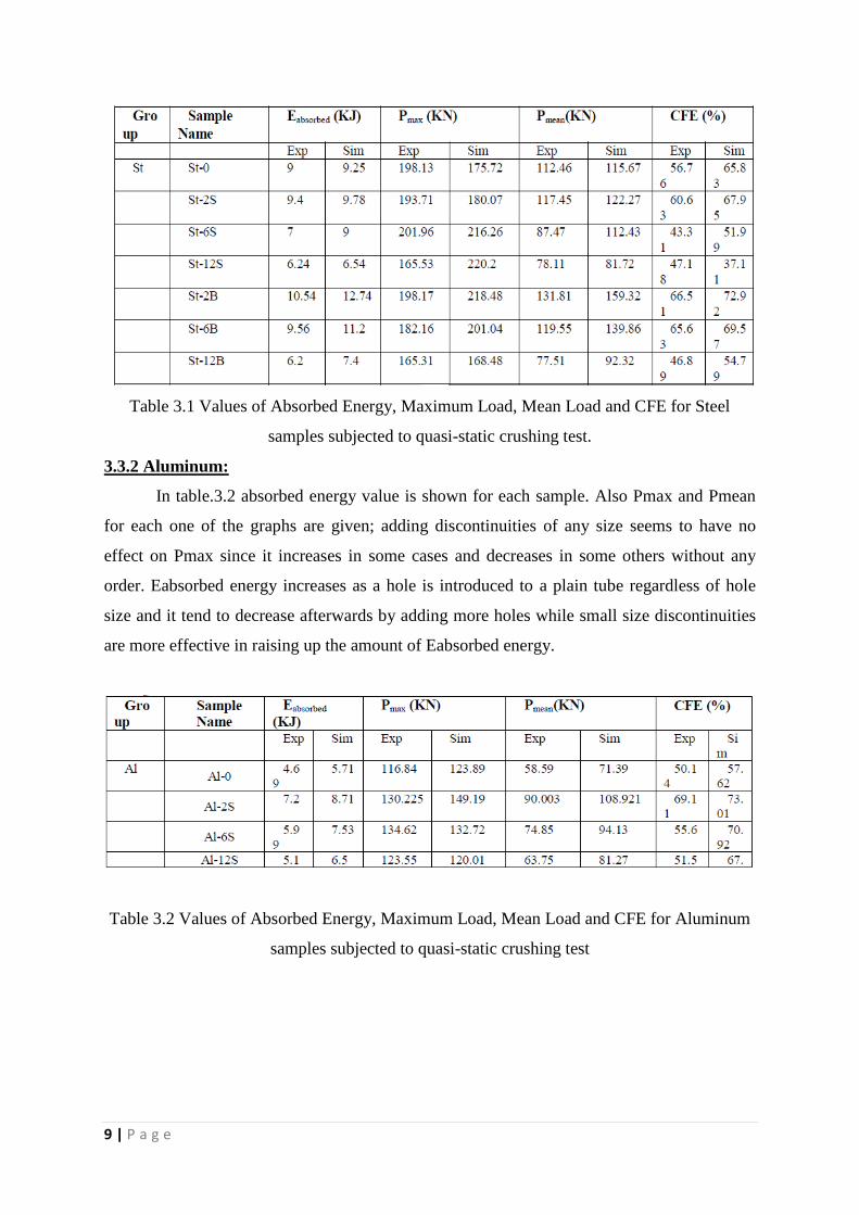
As shown in table.3.1 absorbed energy Eabsorbed energy increases when one pair of
holes is introduced to the plain tube; this increase will be more as the size of the discontinuity
increases. Pmax seems to be regardless of hole size and number of the holes in steel tubes.
CFE and Pmean are following same trend as Eabsorbed energy. CFE has maximum value at
sampleSt-2B and minimum value at sample St-6S, therefore the sample with only one pair of
discontinuities of small size acts more effectively in absorbing crush energy. Simulation
could truly predict the behavior of the samples in experimental situation since they are nearly
following same pattern in load-displacement
9 | P a g e
Table 3.1 Values of Absorbed Energy, Maximum Load, Mean Load and CFE for Steel
samples subjected to quasi-static crushing test.
3.3.2 Aluminum:
In table.3.2 absorbed energy value is shown for each sample. Also Pmax and Pmean
for each one of the graphs are given; adding discontinuities of any size seems to have no
effect on Pmax since it increases in some cases and decreases in some others without any
order. Eabsorbed energy increases as a hole is introduced to a plain tube regardless of hole
size and it tend to decrease afterwards by adding more holes while small size discontinuities
are more effective in raising up the amount of Eabsorbed energy.
Table 3.2 Values of Absorbed Energy, Maximum Load, Mean Load and CFE for Aluminum
samples subjected to quasi-static crushing test
10 | P a g e
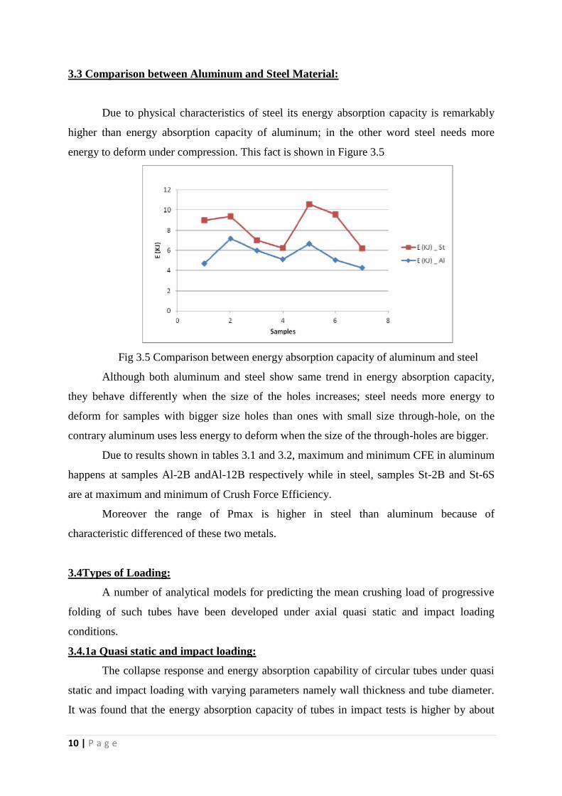
3.3 Comparison between Aluminum and Steel Material:
Due to physical characteristics of steel its energy absorption capacity is remarkably
higher than energy absorption capacity of aluminum; in the other word steel needs more
energy to deform under compression. This fact is shown in Figure 3.5
Fig 3.5 Comparison between energy absorption capacity of aluminum and steel
Although both aluminum and steel show same trend in energy absorption capacity,
they behave differently when the size of the holes increases; steel needs more energy to
deform for samples with bigger size holes than ones with small size through-hole, on the
contrary aluminum uses less energy to deform when the size of the through-holes are bigger.
Due to results shown in tables 3.1 and 3.2, maximum and minimum CFE in aluminum
happens at samples Al-2B andAl-12B respectively while in steel, samples St-2B and St-6S
are at maximum and minimum of Crush Force Efficiency.
Moreover the range of Pmax is higher in steel than aluminum because of
characteristic differenced of these two metals.
3.4Types of Loading:
A number of analytical models for predicting the mean crushing load of progressive
folding of such tubes have been developed under axial quasi static and impact loading
conditions.
3.4.1a Quasi static and impact loading:
The collapse response and energy absorption capability of circular tubes under quasi
static and impact loading with varying parameters namely wall thickness and tube diameter.
It was found that the energy absorption capacity of tubes in impact tests is higher by about
11 | P a g e
1.56-12.3% than quasi static tests, whereas the increase in the initial peak load is between
14.33-40.25%. Moreover, an important finding is that both crush load and energy absorption
capacity increase with increasing thickness and diameter.
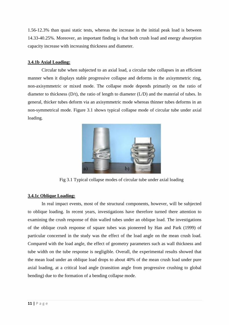
3.4.1b Axial Loading:
Circular tube when subjected to an axial load, a circular tube collapses in an efficient
manner when it displays stable progressive collapse and deforms in the axisymmetric ring,
non-axisymmetric or mixed mode. The collapse mode depends primarily on the ratio of
diameter to thickness (D/t), the ratio of length to diameter (L/D) and the material of tubes. In
general, thicker tubes deform via an axisymmetric mode whereas thinner tubes deforms in an
non-symmetrical mode. Figure 3.1 shows typical collapse mode of circular tube under axial
loading.
Fig 3.1 Typical collapse modes of circular tube under axial loading
3.4.1c Oblique Loading:
In real impact events, most of the structural components, however, will be subjected
to oblique loading. In recent years, investigations have therefore turned there attention to
examining the crush response of thin walled tubes under an oblique load. The investigations
of the oblique crush response of square tubes was pioneered by Han and Park (1999) of
particular concerned in the study was the effect of the load angle on the mean crush load.
Compared with the load angle, the effect of geometry parameters such as wall thickness and
tube width on the tube response is negligible. Overall, the experimental results showed that
the mean load under an oblique load drops to about 40% of the mean crush load under pure
axial loading, at a critical load angle (transition angle from progressive crushing to global
bending) due to the formation of a bending collapse mode.
12 | P a g e
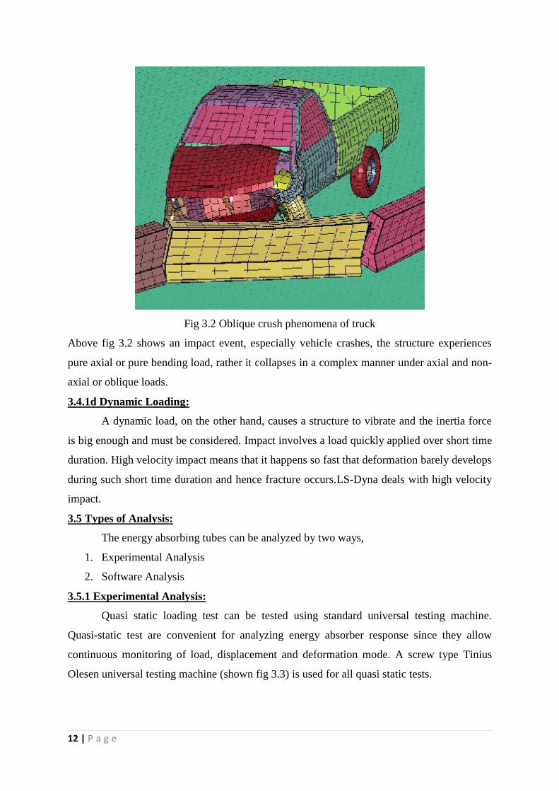
Fig 3.2 Oblique crush phenomena of truck
Above fig 3.2 shows an impact event, especially vehicle crashes, the structure experiences
pure axial or pure bending load, rather it collapses in a complex manner under axial and non-
axial or oblique loads.
3.4.1d Dynamic Loading:
A dynamic load, on the other hand, causes a structure to vibrate and the inertia force
is big enough and must be considered. Impact involves a load quickly applied over short time
duration. High velocity impact means that it happens so fast that deformation barely develops
during such short time duration and hence fracture occurs.LS-Dyna deals with high velocity
impact.
3.5 Types of Analysis:
The energy absorbing tubes can be analyzed by two ways,
1. Experimental Analysis
2. Software Analysis
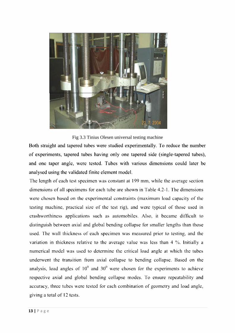
3.5.1 Experimental Analysis:
Quasi static loading test can be tested using standard universal testing machine.
Quasi-static test are convenient for analyzing energy absorber response since they allow
continuous monitoring of load, displacement and deformation mode. A screw type Tinius
Olesen universal testing machine (shown fig 3.3) is used for all quasi static tests.
13 | P a g e
Fig 3.3 Tinius Olesen universal testing machine
14 | P a g e
3.5.2 Software Analysis:
There are explicit non-linear finite element (FE) codes that implement numerical
studies for dynamic crush response of energy absorbers, Such as LS-DYNA3D, ABAQUS,
and LS-DYNA. But most researchers prefer LS-DYNA for software analysis. The main
typical applications of LS-DYNA are crash and vehicular simulations, impact analysis, metal
forming and drop tests. The ability of LS-DYNA to treat various contact algorithms for
different materials is anticipated to be highly useful in the design and analysis of the tubes.
Main areas of application
The numerous features of LS-DYNA enable the software to be employed in many
different fields. A list of common applications is given below,
Crashworthiness simulations of automobiles, trains, and ships
Emergency airplane landings
Occupant safety analysis
Pedestrian safety analysis
Automotive parts manufacture
Car bodies:
-Seats
- Roofs
- Doors
- Hoods
- Bumpers
- Crash boxes
- Girders
- Steering wheels
- Steering columns
- Dash-boards
- Padding
Metal forming:
- Rolling
- Extrusion
- Forging
- Casting
- Spinning
15 | P a g e
- Ironing
- Superplastic forming
- Sheet metal stamping
- Profile rolling
- Deep drawing
- Hydroforming
- Multi-stage processes
- Spring back
- Hemming
Metal cutting
Glass forming
Biomedical applications
Stability/failure investigations
Drop tests
- Consumer products
- Nuclear vessels
Earthquake engineering
Bird strike
Jet engine blade containment
Penetration
Plastics, mold, and blow forming
Blast loading
Spot welded, riveted and bolted structures
Shipping containers
Can and container design
LS-DYNA is a highly advanced general purpose nonlinear finite element program that is
capable of simulating complex real world problems. The distributed and shared memory
solver provides very short turnaround times on desktop computers and clusters operated using
Linux, Windows, and UNIX.
16 | P a g e
Chapter 4
CASE STUDY
By carrying out finite element simulation, energy absorption values of thin-walled
tubes with different geometric dimensions were investigated. Square, circular, and elliptic
tubes of steel and aluminum were used to compare energy absorption. The experimental
results of load-displacement used for verification in the square steel tubes showed good
agreement. Three-dimensional simulation was accomplished with a finite element method
while the impact or collided with one side of tube and the other side was kept rigid. Square
tubes for 2 specified widths with 2 different thicknesses were also compared. In addition, 2
other cross sections including circle and ellipse with the same area were studied for
comparison in a load displacement curve. The results show that the ellipse cross section had
more energy absorption than the 2 others. Moreover, the amount of energy absorption will be
greater with increasing thickness for smaller section tubes.
4.1 Observation Parameters:
In the laboratory test, load, displacement and rotation of jack were measured and the
following response parameters were obtained based on these measurement.
Peak force
Absorbed energy
Mean (crush) force
Deformation mode
4.1.1 Peak force:
The peak force is the maximum of the force displacement curve related to the
formation of the first local buckle in the column i.e. it appears in the initial phase of the test.
17 | P a g e
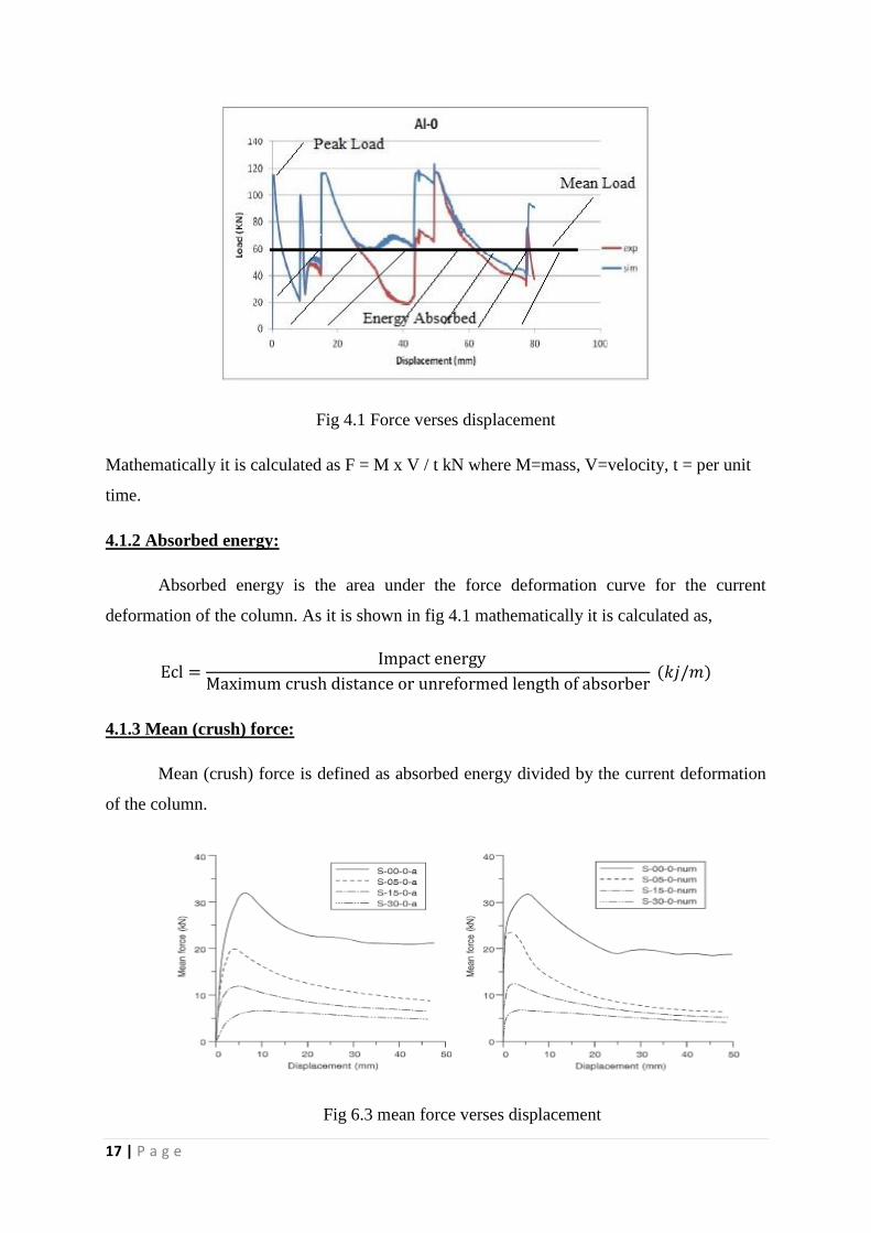
Fig 4.1 Force verses displacement
Mathematically it is calculated as F = M x V / t kN where M=mass, V=velocity, t = per unit
time.
4.1.2 Absorbed energy:
Absorbed energy is the area under the force deformation curve for the current
deformation of the column. As it is shown in fig 4.1 mathematically it is calculated as,
4.1.3 Mean (crush) force:
Mean (crush) force is defined as absorbed energy divided by the current deformation
of the column.
Fig 6.3 mean force verses displacement
18 | P a g e
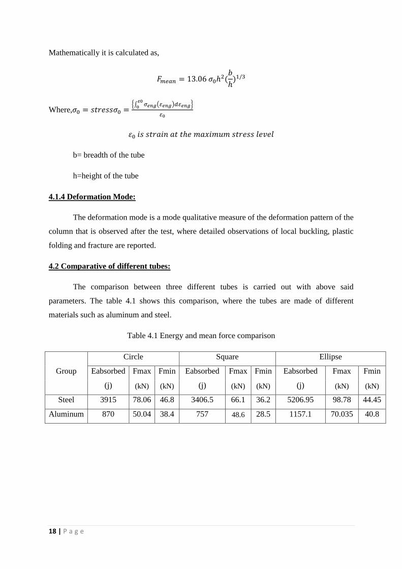
Mathematically it is calculated as,
Where, {∫ ( )
}
b= breadth of the tube
h=height of the tube
4.1.4 Deformation Mode:
The deformation mode is a mode qualitative measure of the deformation pattern of the
column that is observed after the test, where detailed observations of local buckling, plastic
folding and fracture are reported.
4.2 Comparative of different tubes:
The comparison between three different tubes is carried out with above said
parameters. The table 4.1 shows this comparison, where the tubes are made of different
materials such as aluminum and steel.
Table 4.1 Energy and mean force comparison
Group
Circle Square Ellipse
Eabsorbed Fmax Fmin Eabsorbed Fmax Fmin Eabsorbed Fmax Fmin
(j) (kN) (kN) (j) (kN) (kN) (j) (kN) (kN)
Steel 3915 78.06 46.8 3406.5 66.1 36.2 5206.95 98.78 44.45
Aluminum 870 50.04 38.4 757 48.6 28.5 1157.1 70.035 40.8
19 | P a g e
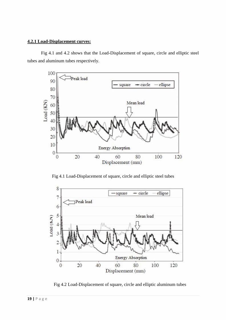
4.2.1 Load-Displacement curves:
Fig 4.1 and 4.2 shows that the Load-Displacement of square, circle and elliptic steel
tubes and aluminum tubes respectively.
Fig 4.1 Load-Displacement of square, circle and elliptic steel tubes
Fig 4.2 Load-Displacement of square, circle and elliptic aluminum tubes
20 | P a g e
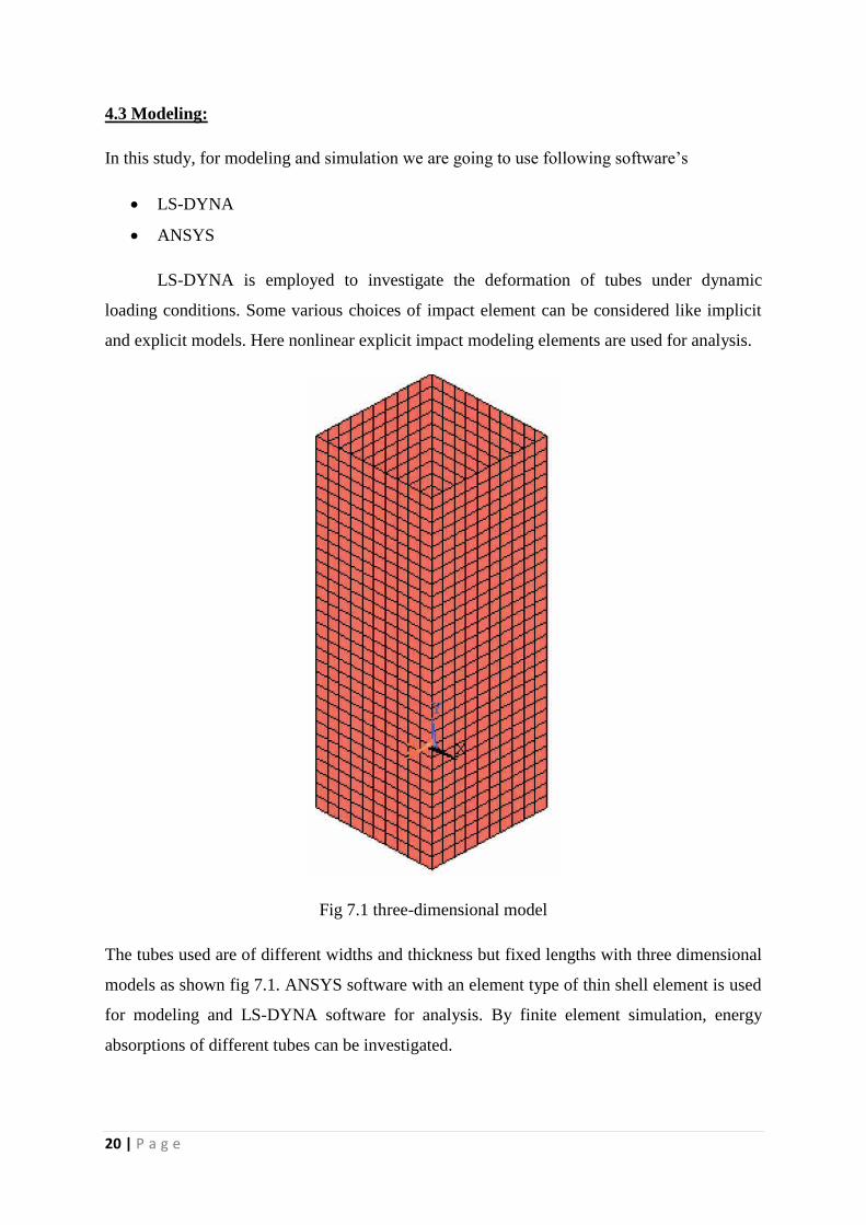
4.3 Modeling:
In this study, for modeling and simulation we are going to use following software’s
LS-DYNA
ANSYS
LS-DYNA is employed to investigate the deformation of tubes under dynamic
loading conditions. Some various choices of impact element can be considered like implicit
and explicit models. Here nonlinear explicit impact modeling elements are used for analysis.
Fig 7.1 three-dimensional model
The tubes used are of different widths and thickness but fixed lengths with three dimensional
models as shown fig 7.1. ANSYS software with an element type of thin shell element is used
for modeling and LS-DYNA software for analysis. By finite element simulation, energy
absorptions of different tubes can be investigated.
21 | P a g e
Chapter 5
CONCLUSION
In this seminar axial crushing of steel and aluminium tubes between two parallel
plates subjected to impact dynamic axial and oblique loading were studied. A nonlinear finite
element model was developed and analyzed with LS-DYNA in this simulation. Typical
deformation histories for three sectional types (square, circle, ellipse, hexagon, octagon,
triangular) were studied and presented. It is concluded that elliptic tubes absorbed more
energy during collisions. The effects of width and thickness were also studied. It is concluded
that energy absorption may be increased about 22% with width enhancement of 66%,
showing that the energy absorption will be more with increasing thickness for smaller section
tubes. Energy per weight absorption during the collision of two metals (steel and aluminium)
is also studied and compared. The study showed that the amount of energy absorption per
weight of steel tube is about 4.5 times greater than the aluminium tube for all three sections,
square, circle and ellipse. However the square section and then the circular section of the
steel tube absorbed energy per weight more than the elliptic section of the aluminium tube. A
comparative study showed that multi-cell sections have greater specific absorption of energy,
in comparison with simple section especially for triangular geometry.
22 | P a g e
Chapter 6
REFERENCES
1. Javad Marzbanrad, Mehdi Mehdikhnlo, Ashkan Saeedi Pour “An energy absorption
comparison of square, circular, and elliptic steel and aluminum tubes under impact
loading” ,2009.
2. A.AlaviNian,M Parsapour “Comparative analysis of energy absorption capacity of
simple and multi-cell thin-walled tubes with triangular, square, hexagonal and
octagonal sections”,2013.
3. T Bovik,O S Hopperstad, A Reyes, M Langseth, G Solomosnad T Dyngeland “Empty
and foam filled circular aluminium tubes subjected to axial and oblique quasi static
loading”, 2003.
4. Md. Reyaz Ur Rahimí A.K. Upadhyay K.K. Shukla “Energy absorption by circular
tubes subjected to oblique loading”, 2014.
5. Yong Zhang, Guangyong Sun, Guangyao Li , Zhen Luo , Qing Li “Optimization of
foam filled bi-tubal structures for crashworthiness criteria ”, 2012.
6. Abramowicz, W. and Jones, N., “Dynamic Axial Crushing of Square Tubes”, Int. J.
Impact Eng., 2, 179-208, 1984.
7. Aljawi, A.A.N., Abd-Rabou, M. and Asiri, S., “Finite Element and Experimental
Analysis of Square Tubes under Dynamic Axial Crushing”, European Congress on
Computational Methods in Applied Sciences and Engineering, 2004.
8. Babbage, J.M. and Mallick, P.K., “Static Axial Crush Performance of Unfilled and
Foam-Filled Aluminum–CompositeHybrid Tubes “, Composite Structures 70, 177-
184, 2005.
9. DiPaolo, B.P., Monteiro, P.J.M. and Gronsky, R., “Quasi-Static Axial Crush
Response of a Thin-Wall, Stainless Steel Box Component” International Journal of
Solids and Structures 41, 3707-3733, 2004.
10. Hanssen, A.G., Langseth, M. and Hopperstad, O.S., “Optimum Design for Energy
Absorption of Square Aluminum Columns with Aluminum Foam Filler Structural
Impact”, International Journal of Mechanical Sciences, 43153-176, 2001.

23 | P a g e
ABSTRACT