self potential (sp) method - kau.edu.sakau.edu.sa/files/0003035/subjects/sp.pdf · self‐potential...
TRANSCRIPT

Self‐potential (SP) Method•or spontaneous polarization method is based on the surface measurement of natural potentials resulting from electrochemical reactions in the subsurface.subsurface.
•does not require electric currents to be injected into the ground as in the RESISTIVITY & IP methodsRESISTIVITY & IP methods.
•has been used in base metal exploration, to detect the presence of massiveb di i t t t th IP th d hi h i d t d i tl tore bodies, in contrast to the IP method which is used to predominantly to
investigate disseminated ore bodies.
•has been increasingly used in groundwater & geothermal investigations, environmental and engineering applications‐‐‐> mapping seepage flow associated with dams, geological mapping, delineate shear zones and near‐associated with dams, geological mapping, delineate shear zones and nearsurface faults.
•ranks as the cheapest of surface geophysical methods in terms of•ranks as the cheapest of surface geophysical methods in terms of equipment necessary and amongst the simplest to operate in the field.

Occurrence of Self‐potentials•SP method is passive, i.e. differences in natural ground potentials are measured between any two points on the ground surface.
•The potentials measured can range from < a millivolt (mV) to > 1 Volt.
• + or – sigh of the potential is an important diagnostic factor in the interpretation of SP anomaliesinterpretation of SP anomalies.
•Self‐potentials are generated by a number of natural sources (exactSelf potentials are generated by a number of natural sources (exact physical processes still unclear).

Occurrence of Self‐potentials•Natural ground potentials consist of 2 components
1. Background Potentials‐‐‐fluctuate with time caused by different1. Background Potentials fluctuate with time caused by different processes ranging from AC currents induced by thunderstorms, variations in Earth’s magnetic fields, effects of heavy rainfalls
2. Mineral Potentials‐‐‐constant due to electrochemical processes


h l d f ll l
Mechanism of Self‐potentials•Some physical processes caused sources of SP are still unclear. •Groundwater is thought to be common factor responsible for SP.P t ti l t d b th fl f t b t ti•Potentials are generated by the flow of water, by water reacting as an electrolyte and as a solvent of different minerals.
•Electrical conductivity to produce potentials of porous rocks depends on porosity and on mobility of water to pass through the pore spaces ‐‐‐depend on ionic mobilities, solution concentrations, viscosity,depend on ionic mobilities, solution concentrations, viscosity, temperature & pressure.
•There are a few types of SP :•There are a few types of SP :1.Electrokinetic potential2 Thermoelectric potential2. Thermoelectric potential3. Electrochemical potential4. Mineral/mineralization potential/ p

Fl i f fl id ( l t l t ) th h ill
Electrokinetic potential• Flowing of fluid (electrolyte) through a capillary or porous
medium generates potentials along the flow path.
• The potentials are alternatively called as electrofiltration• The potentials are alternatively called as electrofiltration,electromechanical or streaming potentials.
• The effect is believed to be due to electrokinetic couplingThe effect is believed to be due to electrokinetic couplingbetween the fluid ions and the walls of the capillary.
• The electrokinetic potential (Ek) generated between the ends ofThe electrokinetic potential (Ek) generated between the ends of the capillary passage is given by
= Dielectric permittivity of pore fluid
= Electrical resistivity of pore fluid
= Electrofiltration coupling coefficient
= Pressure difference
= Dynamic viscosity of pore fluid

E di t i i th di ti th di t i
Electrokinetic potential• Ek gradient is in the same direction as the pressure gradient, i.e.
opposite to the direction of the electrolyte flow.
• E normally providse amplitudes of some mV to several hundreds• Ek normally providse amplitudes of some mV to several hundreds of mV.
• Ek can be found associated with flow of subsurface water andEk can be found associated with flow of subsurface water and thermal fluids
• Ek effects have been observed over zones of water leakageEk effects have been observed over zones of water leakage through fissures in the rock floor of reservoirs, over terrains with large elevation changes, and in geothermal areas.
P t ti l di t ill k l if
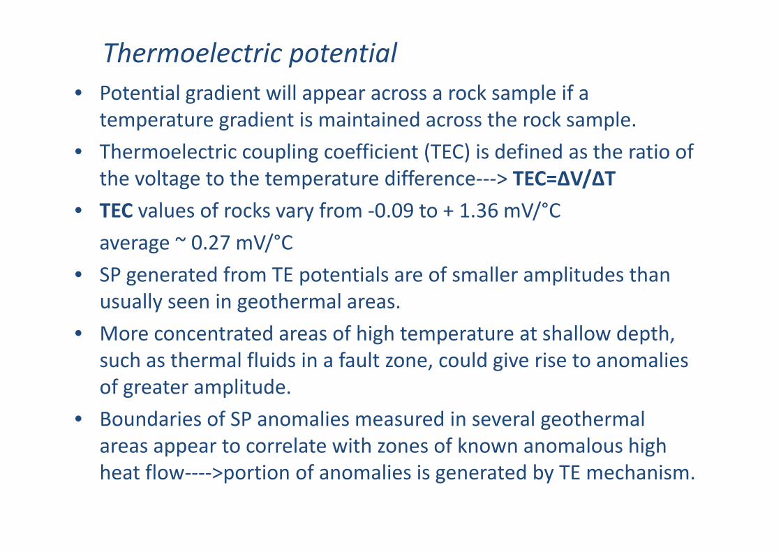
Thermoelectric potential• Potential gradient will appear across a rock sample if a
temperature gradient is maintained across the rock sample.
• Thermoelectric coupling coefficient (TEC) is defined as the ratio of• Thermoelectric coupling coefficient (TEC) is defined as the ratio of the voltage to the temperature difference‐‐‐> TEC=∆V/∆T
• TEC values of rocks vary from ‐0 09 to + 1 36 mV/°CTEC values of rocks vary from 0.09 to + 1.36 mV/ C
average ~ 0.27 mV/°C
• SP generated from TE potentials are of smaller amplitudes than• SP generated from TE potentials are of smaller amplitudes than usually seen in geothermal areas.
• More concentrated areas of high temperature at shallow depth,More concentrated areas of high temperature at shallow depth, such as thermal fluids in a fault zone, could give rise to anomalies of greater amplitude.
• Boundaries of SP anomalies measured in several geothermal areas appear to correlate with zones of known anomalous high heat flow‐‐‐‐>portion of anomalies is generated by TE mechanism.
If th t ti f th l t l t i th d i l ll
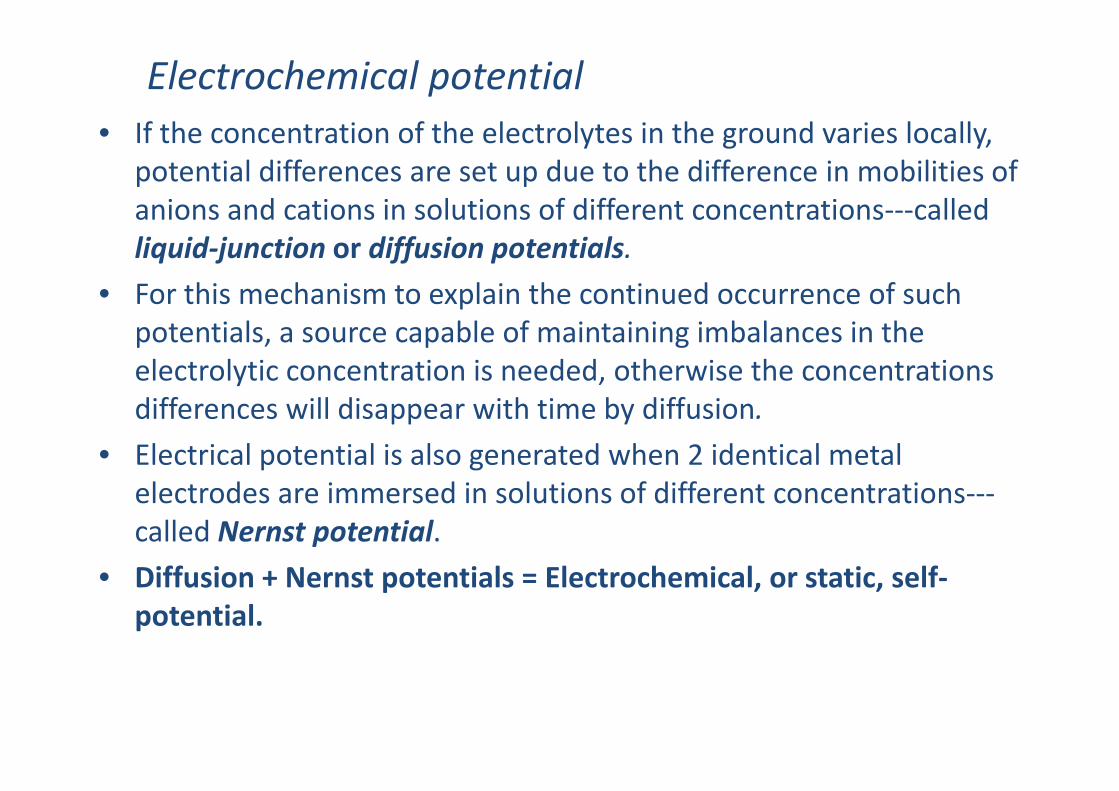
Electrochemical potential• If the concentration of the electrolytes in the ground varies locally,
potential differences are set up due to the difference in mobilities of anions and cations in solutions of different concentrations‐‐‐calledanions and cations in solutions of different concentrations called liquid‐junction or diffusion potentials.
• For this mechanism to explain the continued occurrence of such ppotentials, a source capable of maintaining imbalances in the electrolytic concentration is needed, otherwise the concentrations differences will disappear with time by diffusion.
• Electrical potential is also generated when 2 identical metal l t d i d i l ti f diff t t tielectrodes are immersed in solutions of different concentrations‐‐‐called Nernst potential.
• Diffusion + Nernst potentials = Electrochemical or static self• Diffusion + Nernst potentials = Electrochemical, or static, self‐potential.

O f th t t l l t l t i N Cl
Electrochemical potential• One of the most common natural electrolytes is NaCl.
• For NaCl solutions of different concentration (C1,C2) but at the same temperature T (°C) the amplitude of the electrochemical potentialtemperature, T ( C), the amplitude of the electrochemical potential (Ec) is given by
• For example, if C1:C2 = 5:1 ‐‐‐‐‐> Ec ≈ 50 mV

i th t i t t i i l l ti f SP i t d ith
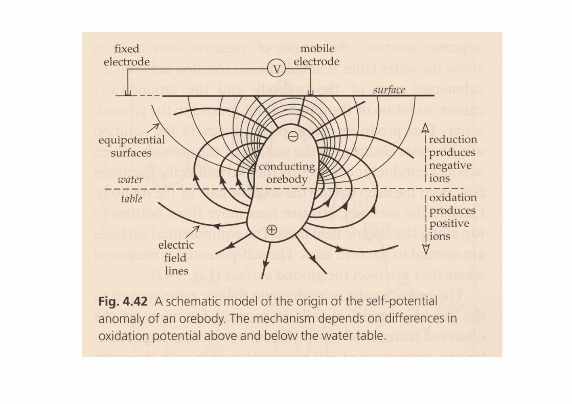
Mineral potential• is the most important in mineral exploration of SP associated with
massive sulphide ore bodies.
• Large negative ( ) SP anomalies (100 1000mV)can be observed• Large negative (‐) SP anomalies (100‐1000mV)can be observed particularly over deposits of pyrite, chalcopyrite, pyrrhotite, magnetite, and graphite.g , g p
• The potentials are almost invariably negative over the top of the deposit and are quite stable in time.
• Sato and Mooney (1960) have provided the most complete explanation of the electrochemical processes caused the observed SP anomalies.
• However this hypothesis does not explain all the occurrences of the SP i di h h l h i l li dSP indicates that the actual physical processes are more complicated and no yet truly understood.

Measurement of Self‐potentials
• simple and inexpensive.
• 2 non‐polarizable porous‐pot electrodes connected to a precision p p p pvoltmeters capable of measuring to at least 1 mV
• Each electrode is made up of a copper electrode dipped in a saturated solution of copper sulphate which can percolate through the porous base to the pot.
• An alternate zinc electrode in saturated zinc sulphate solution or silver in silver chloride can be used.
Maximum depth of sensitivity of SP method = ~60‐100m depending b d d t f b don ore body and nature of overburden.

Porous pot electrodes

2 fi ld t h i 2 l t d fi ti
Measurement of Self‐potentials
2 field techniques or 2 electrode configurations
1.Potential gradient method (dipole/leap frog/gradient configuration)
fi i f 2 l d (5 10 )‐fix separation of 2 electrodes (5 or 10 m)
‐measure potential difference between 2 electrodes = potential gradient [mV/V]gradient [mV/V]
‐2 porous are leap‐frogged along traverse with care of correct polarity of potential recordedof potential recorded
‐observation points = midpoint between 2 electrodes

Measurement of Self‐potentials
2.Potential amplitude, or total field method (fixed‐base) configuration
‐keep one electrode fixed at a base station
‐measure potential difference [mV] between base & 2nd
electrodes moving along traverse
‐lower level of cumulative errors & confusing polarity
‐disadvantages of transporting long wire

Interpretation of Self‐Potential Data
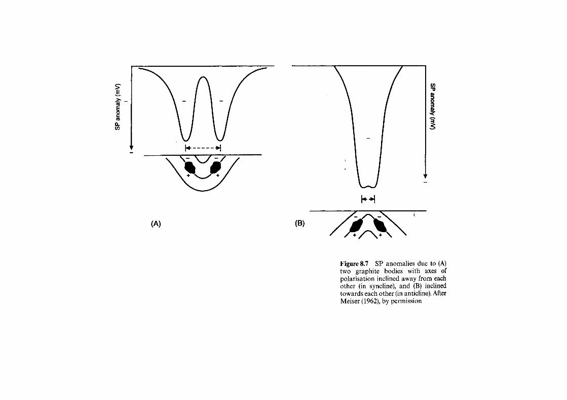
• SP anomalies are often interpreted qualitatively by– Profile shape
– Amplitude
– Polarity (+ or ‐)
C– Contour pattern
• Top of ore body is assumed to lie directly beneath position of minimum potentialminimum potential.
• For quantitative interpretation, it is possible to calculate the potential distributions around polarized bodies of simple shape,potential distributions around polarized bodies of simple shape, such as sphere, ellipsoid, and dipole, by making some simplifications and assumptions concerning the potential on the surface of the sources.
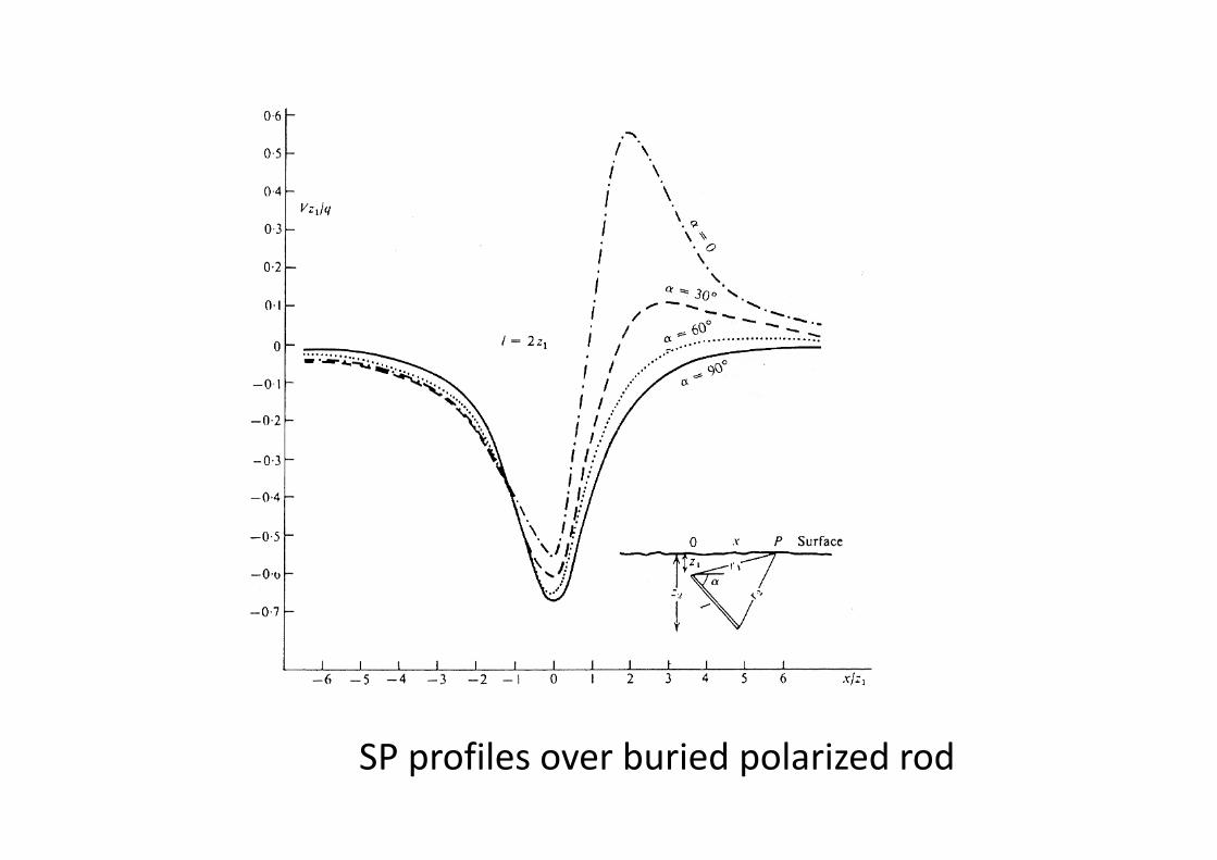
SP profiles over buried polarized rod

SP fil b i d l i d hSP profiles over buried polarized sphere


mV]
SP [m
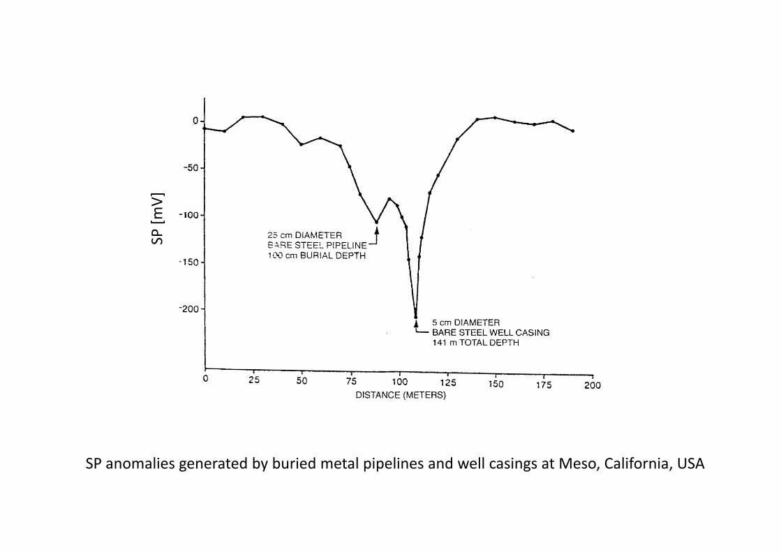
SP anomalies generated by buried metal pipelines and well casings at Meso California USASP anomalies generated by buried metal pipelines and well casings at Meso, California, USA


An SP profile across pegmatite dikes in gneiss