selection reselection umts presentaion
TRANSCRIPT

IDLE MODE BEHAVIOUR AND CONNECTED MODE BEHAVIOUR IN CELL_FACH STATE

Agenda
• Introduction• PLMN selection• Cell selection• Cell reselection• Location area (LA) and Routing area (RA) updating• Paging• System information broadcast• CELL_FACH State

1.1 Introduction• Idle mode
– No connection to radio network (No RRC connection established)– This minimizes resource utilization in UE and the network– UE must be able to access the system and be reached by system with reasonable delays
• CELL_FACH mode– User Equipment (UE) in Connected Mode (has an RRC Connection to radio network) – UE uses the common transport channels RACH or FACH
• CELL_DCH mode– User Equipment (UE) in Connected Mode (has an RRC Connection to radio network)– UE uses dedicated channels for transmitting data and signalling

1.2 Idle mode
• Functions performed– PLMN Selection– Cell Selection and Reselection– Location Area (LA) and Routing Area (RA) updating– Paging– System Information Broadcast

1.3 PLMN Selection
• PLMN selection performed upon power on or upon recovery from lack of coverage
• If there is no last registered PLMN, or if it is unavailable, the UE will try to select another PLMN “AUTOMATICALLY” or “MANUALLY” depending on its operating mode
• Manual mode– UE displays all PLMN’s (allowed and not allowed) by scanning all frequency carriers– The user makes a manual selection and the UE attempts registration on the PLMN

1.3 PLMN Selection (Contd)
•In automatic mode, if no last registered PLMN exists or is available, the UE selects a PLMN in the following order of priority
•Each PLMN in the user-controlled PLMN list in the USIM, in order of priority•Each PLMN in the operator-controlled PLMN list in the USIM•Other PLMN’s according to the high-quality criterion (WCDMA: CPICH RSCP >= -95 dBm; GSM: SS >= -85 dBm)•Other PLMN’s, in order of decreasing signal strength

1.3 PLMN selection (Contd)
• Roaming is a service through which a UE is able to obtain services from another PLMN
• The UE in Automatic mode, having selected and registered a Visited PLMN (VPLMN) periodically attempts to return to its Home PLMN (HPLMN)
• The time interval between consecutive attempts is stored in the USIM and is managed by the network operator using a timer.
– The timer may have a value between 6 minutes and 8 hours with a step size of 6 minutes. A default value is 30 minutes.

1.4 Cell Selection
• UE looks for a suitable cell in the selected PLMN and camps on to it
• Cell search procedure– UE acquires slot synchronization using P-SCH– It acquires frame synchronization using S-SCH– Primary scrambling code is obtained from CPICH
• UE then monitors the paging and system information, performs periodical radio measurements and evaluates cell reselection criteria
• WCDMA is sensitive to intra frequency interference– Measurements used in cell selection and cell re-selection not only relate to signal strength
but also to quality of CPICH

1.4 Cell Selection• Strategies used for the cell selection process:
– Initial Cell Selection: UE has no knowledge of the WCDMA radio channels• UE scans all WCDMA radio frequency channels to find a suitable cell with the highest
signal level and read BCCH• The PLMN is determined from the mcc and mnc in the MIB in BCCH
– Stored Information Cell Selection: UE knows the carrier frequencies that have previously been used

1.4.1 Cell Selection Procedure (Contd)

1.4.1 Cell selection procedure (Contd)• For cell selection criteria the UE calculates
Squal = Qqualmeas - qQualMin (for WCDMA cells)Srxlev = Qrxlevmeas - qRxLevMin – Pcompensation (for all cells)
Where Pcompensation = max(maxTxPowerUL – P,0)P is output power of UE according to class
• Cell selection criteria (S criteria) is fulfilled whenSqual>0 ( for WCDMA cells only)and Srxlev>0
• Recommended valuesqQualMin= -19dB (Values in BLUE are values of the parameters)qRxLevMin= -115dBmNote: Increase qRxLevMin if primaryCpichPower is increased to make cell size constant.
(maxTxPowerUL = 24)

1.5 Cell reselection• UE ranks available cells using R criteria
R(Serving) = Qmeas(s) + qHyst(s)R(Neighbour) = Qmeas(n) – qOffset(s,n)
Qmeas is the quality value of the received signal– Derived from the averaged received signal level for GSM cells– Derived from CPICH Ec/Io or CPICH RSCP for WCDMA cells depending on the value of
qualMeasQuantity (2, Ec/Io)
qHyst(s) = qHyst1 when ranking based on CPICH RSCP (4)qHyst(s) = qHyst2 when ranking based on CPICH Ec/Io (4)qOffset(s,n) = qOffset1sn when ranking based on CPICH RSCPqOffset(s,n) = qOffset2sn when ranking based on CPICH Ec/IoThe above two values are 0 for WCDMA cells and 7 for GSM cells

1.5 Cell reselection (Contd)
• The ranking is first based on RSCP– If a GSM cell is the best cell, the UE reselects to that cell– If a WCDMA cell is the best cell, the UE again performs ranking on a parameter depending
on qualMeasQuantity and then performs cell reselection
• The UE will reselect a new cell if it is better ranked than the serving cell for a time interval of treSelection (1)
• Intra frequency measurementsIf Squal < SIntraSearch, the UE performs Intra-Freq measurements (22)Remember: Squal = Qqualmeas – qQualMin
• Inter frequency measurementsIf Squal < SInterSearch, the UE performs Inter-Freq measurements (0)
• Inter-RAT measurementsIf Squal < SRatSearch or Srxlev<sHcsRat, the UE performs Inter-RAT measurements (4 and -105)

1.6 Location and Routing Area updating
• If the Location Area Identity (LAI) or Routing Area Identity (RAI) read on system information is different to the one stored on the USIM, the UE performs a LA or RA registration update
• Three types of registration update– Normal– Periodic– IMSI attach/detach
• Periodic update – T3212 is the time interval between two periodic LA updates (10 (60min))– T3312 is the time interval between two periodic RA updates (9 (54min))
• IMSI attach/detach used if att = 1 (1)– UE sends “attach” or “detach” messages when the UE is powered on or off

1.7 Paging
• Two types of paging– Core Network informs a UE of a terminating service request – RAN informs all UE’s that the system information has been modified
• Paging messages sent to all UE’s in LA or RA – trade-off between the number of registration attempts and the paging load which depends
on the size of the LA or RA
• PICH is used to indicate to the UE when it should read the S-CCPCH– Number of times RAN pages the UE is determined by noOfPagingRecordTransm (2)

1.7 Paging [Contd.]
• Discontinuous Reception– UE listens to PICH at predefined
times only– The time interval Discontinuous
Reception (DRX) cycle = (2^k) * 10 (ms)where k = cnDrxCycleLengthCs (7) for CS and cnDrxCycleLengthPs (7) for PS
• Updated system information from RAN– RAN pages the UE consecutively– The number of times the UE hears it is defined by noOfMaxDrxCycles (1)

1.8 System Information• System parameters are broadcast in BCCH. It has information regarding
– Cell Selection and Reselection– Measurement Management– Location and Routing Registration– Handover– Power Control
• The System Information elements are broadcast in System Information Blocks (SIB’s). Each SIB contains a specific collection of information
• The MIB gives the scheduling information of the SIB’s– Repetition Rate for SIB (sibxRepPeriod where x = 1,3,5,7,11,12)– Start Position for SIB (sibxStartPos where x = 1,3,5,7,11,12)

1.8 System Information [Contd.]
•MIB has a fixed repetition rate of 80ms
•When there is a system information update, the RNC updates the RBS up to a maximum of updateCellReattNo (5)

1.8.1 SIB Contents
1.8.2 System Information Update
• For rereading SIB’s, there are different rules for static and dynamic SIB’s
• For static SIB’s, when the information changes, the corresponding value tag in the MIB changes
• When any SIB is modified, the RAN pages all UE’s with the information element “BCCH modification info”
• Dynamic SIB’s (SIB7) are not linked to value tags in MIB– Expiration time is used as the reread mechanismExpiration time = sib7RepPeriod * sib7expirationTimeFactor (1)

1.8.3 SIB Characteristics
• SIB1 has two parts– Update part, updated when content is changed– Area part corresponding to LA and RA configured by sib1PLMNScopeValuetag

1.9 CELL_FACH State
• In Cell_FACH state, the UE performs inter-frequency and inter-RAT measurements during FACH measurement occasions if fachMeasOccaCycLenCoeff > 0 (4)
• If the parameter interFreqFDDMeasIndicator = 1, the UE will evaluate cell reselection criteria on inter-frequency cells (0)
• Paging: When a connection exists between the WCDMA RAN and the UE, “Paging Type 2” is sent through dedicated control channels
• System information change: Ue receives a System Information Change Indication message containing the information element “BCCH modification info”

Rx/Tx DIVERSITY & MIMO

Agenda
•Introduction
• Single Antenna
•Transmit Diversity
• Receive Diversity
• MIMO
• MIMO Single User
• MIMO Multi User
• MIMO & Cell Traffic

2.1 Introduction• The multiple-antenna technique is not a synonym of MIMO.
• The main techniques are:1. MIMO2. Beamforming3. Diversity
• The principle is to use several antennas in transmission and/or reception to improve signal robustness and consequently system capacity or coverage

2.2 Single Antenna
• SISO = Single Input Single Output
1. It is the most basic radio channel access mode.2. Only one transmit antenna and one receive antenna are used.3. This is the form of communications that has been the default one since radio has begun. SISO is
the baseline against which all the multiple antenna techniques are compared.
*Using the 1 antenna in transmission and 1 antenna in reception is the standard configuration since the beginning of the telecom.
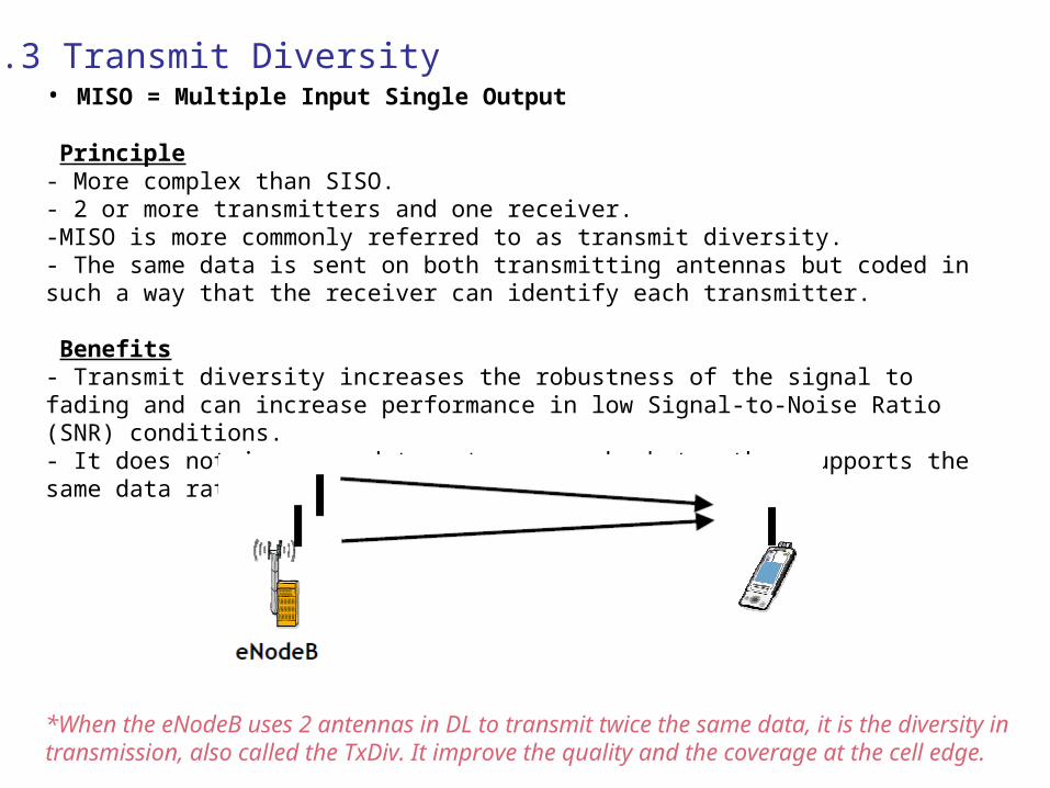
2.3 Transmit Diversity• MISO = Multiple Input Single Output
Principle- More complex than SISO.- 2 or more transmitters and one receiver.-MISO is more commonly referred to as transmit diversity.- The same data is sent on both transmitting antennas but coded in such a way that the receiver can identify each transmitter.
Benefits- Transmit diversity increases the robustness of the signal to fading and can increase performance in low Signal-to-Noise Ratio (SNR) conditions.- It does not increase data rates as such, but rather supports the same data rates using less power.
*When the eNodeB uses 2 antennas in DL to transmit twice the same data, it is the diversity in transmission, also called the TxDiv. It improve the quality and the coverage at the cell edge.

2.4 Receive Diversity•SIMO = Single Input Multiple Output
• Principle- It uses one transmitter and 2 or more receivers.-It is often referred to as receive diversity.
• Benefits- It is particularly well suited for low SNR conditions in which a theoretical gain of 3 dB is possible when two receivers are used.-No change in the data rate since only one data stream is transmitted, but coverage at the cell edge is improved due to the lowering of the usable SNR.
*The UE in UL can transmit only one stream, but with 2 antennas in reception, the eNodeB can receive twice the signal. So it can combine them to improve the reception quality.

2.5 MIMO
•MIMO = Multiple Input Multiple Output
- 2 or more transmitters and 2 or more receivers.- MIMO transmits several streams whereas SIMO or MISO transmits only onestream.-If there are N streams, there will be at least N antennas (here only 2).-By spatially separating N streams across at least N antennas, N receivers will be able to fully reconstruct the original data streams
*MIMO requires N antennas in transmitter and receiver and by this way it can transmit N streams in the same radio resources on the same time. Currently, N=2 and there are 2 2 antennas on the eNodeB and 2 antennas on the UE.
*It allows to transmit 2 TB (Transport Block) on the same subframe for a given UE and by this it boosts the radio performance.
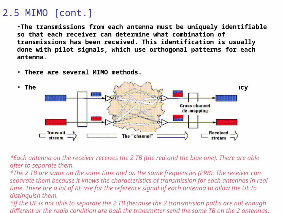
2.5 MIMO [cont.]•The transmissions from each antenna must be uniquely identifiable so that each receiver can determine what combination of transmissions has been received. This identification is usually done with pilot signals, which use orthogonal patterns for each antenna.
• There are several MIMO methods.
• The stream are sent on the same time, on the same frequency
*Each antenna on the receiver receives the 2 TB (the red and the blue one). There are able after to separate them.*The 2 TB are same on the same time and on the same frequencies (PRB). The receiver can separate them because it knows the characteristics of transmission for each antennas in real time. There are a lot of RE use for the reference signal of each antenna to allow the UE to distinguish them.*If the UE is not able to separate the 2 TB (because the 2 transmission paths are not enough different or the radio condition are bad) the transmitter send the same TB on the 2 antennas.

2.6 MIMO Single User
•SU-MIMO = Single User MIMO
• It is the most common form of MIMO. -Each user is served by only one BS and it occupies the resource exclusively, including time, frequency.
• It can be applied in the uplink or downlink. -But it is generally applied only in DL. The UE can easily have 2 antennas in reception but only 1 antenna can transmit
*The Single User MIMO is used in DL and means that the 2 TB send by the 2 antennas using the same radio resources are for the same UE.*In UL, it is not possible to use this MIMO.

2.6 MIMO Single User [cont.]
• There are two operation modes in SU-MIMO spatial multiplexing:1. the closed-loop spatial multiplexing mode- The UE reports the CQI, the RI (Rank Indicator) and the PMI (Precoding Matrix indicator)2. the open-loop spatial multiplexing mode- The reports only the CQI and the RI• The RI (Rank Indicator) indicates the number of spatial layers (data streams) that can be
supported by the current channel experienced at the UE• The PMI (Precoding Matrix Indicator) is the UE feedback
*The required UE feedback for the MIMO are:- RI, Rank Indicator. By this one the UE can indicate if it is able to separate 2 TB. If Yes the eNodeB can use the MIMO. If not it uses the TxDiv- PMI, Precoding Matrix indicator. It is used only for the Closed Loop MIMO. The UE indicates the eNodeB how to map the data on the 2 antennas to optimize the reception.

2.7 MIMO Multi User
•MIMO-MU = Multi user -It is used only in Uplink. -MIMO-MU does not increase the individual user’s data rate but it does offer cell capacity gains that are similar to, or better than, those provided by MIMO-SU. -The UE does not require the expense and power drain of two transmitters, yet the cell still benefits from increased capacity. -The UE must be well aligned in time and power as received at the eNB.
*In UL, the UE can not transmit 2 different signal like it has only 1 amplifier. So to take benefit of the MIMO capabilities, the eNodeB can allocates the same radio resources to 2 UEs (PRB and sub-frame). By this way, he eNodeB boosts the capacity in UL.

2.8 MIMO & Cell Traffic
• The Tx Div can be applied on all the physical channels:
1. Physical DL Shared Channel (PDSCH)2. Physical Broadcast Channel (PBCH)3. Physical Control Format Indicator Channel (PCFICH)4. Physical Downlink Control Channel (PDCCH)
• The other MIMO schemes are only applicable to the PDSCH
*Like the MIMO required a UE-specific feedback (RI and PMI), it is not possible to use it for all the channel.*Only the PSDCH supports the MIMO and only for UE specific data.*For example, the SIB2 is transmitted on the PDSCH but it is received by all the UE, so TxDiv. The HO command is transmitted only to a given UE, so MIMO can be used if criterion are fullfilled.
2.8 MIMO & Cell Traffic [cont.]
• The 3 possible transmission mode are:
1. TxDiV only2. MIMO-SU Open Loop3. MIMO-SU Closed Loop
• Depending on the selected mode, some specific CQI report modes can be configured and some specific DCI can be used