selection of the cupola furnace and fabrication of...
TRANSCRIPT
SELECTION OF THE CUPOLA FURNACE AND
FABRICATION OF THE MODEL
MINI PROJECT REPORT - 2009
Submitted
in partial fulfilment of the requirements for the
Degree of Bachelor of Technology
in Production Engineering
University of Calicut.
Done by
Name of group members
CEASE JUNIOR
FIJO GEORGE
FOUZIYA C M
HAREESH MOHANAN
JESBIN JOSEPH
JIBIN JOSEPH
ABSTRACT
A cupola or cupola furnace is a melting device used in foundries that can be used to melt cast
iron, ni-resist iron and some bronzes. The cupola can be made in almost any practical size. The size of
the cupola is represented or taken on the basis of the melting capacity and the diameters and can range
from 18inches to 13 feet. The overall shape is cylindrical and usually arranged vertically, supported by
4 legs.
Cupola has very complexed reactions. Scrap metal and flux are added from the charging door
and hot air blasted through the tuyeres which actually controls the overall heat. Slag is collected from
the slag hole and hot molten metal from the tap hole. The bottom of the cylinder is fitted with doors
which swing down and out to 'drop bottom'. The top where gases escape can be open or fitted with a
cap to prevent rain from entering the cupola.
The shell of the cupola, being usually made of steel, has refractory brick and refractory
patching material lining it. The bottom is lining in a similar manner but often a clay and sand mixture
may be used, as this lining is temporary. The bottom lining is compressed or 'rammed' against the
bottom doors.
By the mini project we are aiming to fabricate a model of cupola furnace selected on the
selection criteria.
CHAPTERS Page No:
1. INTRODUCTION
FURNACES
ABOUT CUPOLA
OBJECTIVE OF PROJECT
2. CUPOLA IN GENERAL
STRUCTURAL DETAILS
CUPOLA OPERATIONS
PREPARATION OF CUPOLA
LIGHTING THE FIRE IN THE COKE BED
CHARGING OF CUPOLA
MELTING
SLAGGING AND METAL TAPPING
DROPPING DOWN THE CUPOLA BOTTOM
ZONES OF CUPOLA
EFFICIENCY OF CUPOLA
ADVANTAGES AND LIMITATIONS
QUALITY CONTROL
3. SELECTION CRITERIA OF CUPOLA FURNACE FOR FABRICATION
3.1 FABRICATION DIAGRAM
3.2 MELTING CAPACITY
3.3 MATERIALS REQUIRED
4. FABRICATION DETAILS
5. CONCLUSION
6. BIBLIOGRAPHY

LIST OF TABLES
1 . TABLE 3.1 [1]

LIST OF FIGURES
1. Fig 2.12. Fig 3.1

CHAPTER 1
INTRODUCTION
Before pouring the metal into the mold, the metal is to be in the molten or liquid state. A
furnace is used to melt the metal. A foundry furnace rather, remelts the metal to be cast. It is not meant
for carrying out basic melting operations which convert an ore into usable metal. Whereas blast
furnace performs basic melting (of ore) operation, an electric arc, electric resistance etc. Different
furnaces are employed for remelting ferrous and non-ferrous materials. Heat in a remelting furnace is
created by, combustion of fuel, electric arc, electric resistance etc. A furnace contains a high
temperature zone or region surround being insulating minimizes heat losses to the surroundings. Metal
to be remelted is placed in the high temperature region of the furnace.
The development of blast furnace for the reduction of iron ore gave birth to iron founding. At
first, pig iron from the blast furnace was directly used for making iron castings. As time went on and
the use of iron castings were very common , smaller shaft type furnaces were used for remelting pig
iron specifically for making small gray iron castings. Thus evolved the cupola. The first English patent
on a cupola was granted in 1794.
Cupola is employed for melting scrap metal or (over90% of) the pig iron used in production of
Iron castings. It is an economical furnace for the production of gray cast iron, modular cast iron and
some malleable iron castings. Besides iron castings, cupola can be used for melting some copper
alloys also. Cupola can be employed in duplexing and triplexing operations for making steels.
Duplexing and triplexing melting operations employ and three furnaces respectively. Cupola is
obtained in different sizes. Cupola can be operated for as long a time as may be required to produce a
given amount of iron. Cupola does not produce metal of uniform quality. Fuel for cupola is generally a
good grade low-sulphur coke, anthracite coal or carbon briquettes.
The objective of project is to select a cupola furnace for fabricating of the model using the
selection criteria. The fabricated cupola furnace model should be able to explain all the working
conditions.
The cupola is one of the main reasons that hasten up the industrial revolution. It also hasn’t lost
the significance by the arrival of new foundry furnaces. So we decide to fabricate the model of cupola.
Our college would benefit from it since the new syllabus includes foundry practise for all the students.
It would be easier for them to understand the working conditions and to learn them.

CHAPTER 2
CUPOLA
2.1 STRUCTURAL DETAILS
A cupola is a cylindrical shell constructed (welded or riveted) form boiler plate (6 o 10 mm
thick), is open at both its top and bottom and is lined with firebrick and clay. At bottom the cupola is
supported on cast iron legs; the bottom opening of cupola is closed by cast iron which can be made to
open or close and are supported (when closed) by an iron prop (or upright). The bottom opening doors
swing out of the way after the melting operation is over and thus the contents left in the cupola drop
down through the opening (Thus formed). Air form the blower (not shown) comes through the blast
pipe and enters wind box which surrounds the cupola and supply’s air evenly to all the tuyeres.
Tuyeres extend through the steel shell and refractory wall to the combustion zone and supply
air necessary for combustion. The total cross sectional area of the tuyeres is about one fifth to one-
sixth of the cross-sectional area of the cupola. Tuyeres have dimensions 50 mm x 150 mm or 100 mm
x 300 mm. Cupola up to 75 cm diameter may have three to four where as larger ones are fitted with
eight, ten or even more number of tuyeres. Tuyeres may be fitted in one or more number of rows.
Auxiliary tuyeres sometimes provided to raise melting efficiency. The volume of air passing to the
combustion zone can be measured with the help of a volume meter. Normally air pressure is 12 to 16
in., water gauge for small and medium sized cupolas and 16 to 35 in., water gauge for large cupolas. A
cupola using 1 to 1 ratio of iron to coke consumes about 800-900 cubic meters of air to melt one ton of
iron.
There is a tap hole in the cupola from where the molten metal is taken out pour into the molds. The fire
in the cupola is also lit through the tap hole. Opposite the tap hole and a little higher (but about 25 cm
below tuyere centre) is the slag hole. Slag being lighter than metal, floats over the molten metal and is
removed through the slag hole.
Cupola remains either open or has a metal shield or a spark arrester at its top. In addition, a
cupola is provided with a charging platform and a charging door at suitable heights to feed the charge
in cupola. Cupola capacities (size) vary from 1 to 15 tons (or even more) of melted iron per heat.
Certain small cupolas having a capacity of ½ to 1 ton are better called cupolettes. Cupolettes have a
height which varies from 2.5 to 4 metres. Cupolette may be tilted to horizontal position as well. The
height of cupola is commonly about 6 metres. The inside diameters of common cupolas with much
smaller and larger diameters have been operated. Sometimes a cupola may be fitted with a collector,
filter and precipitator to minimize atmospheric pollution.
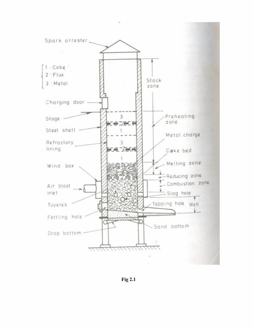
Fig 2.1
2.2 CUPOLA OPERATIONS
A cupola heat includes not only the actual melting operation but all the operations which
precede and follow the period during which iron is being melted. A certain cycle of events occurs each
time a heat is made, including the following:
1. Preparation of the refractory lining, bottom, and tap hole and slag hole
2. Lighting and burning in the coke bed
3. Charging
4. Melting
a. Starting the air blast
b. Charging
5. Tapping and slagging
6. Dropping the bottom
2.2.1 PREPARATION OF CUPOLA
The bottom door is dropped to open. The contents in the cupola left from the previous melting
operation are dumped under the furnace and removed. Slag, coke and iron sticking to the side walls of
the furnace are chipped off. Damaged firebricks are replaced by new ones. The damaged furnace
refractory lining is patched and repaired. Eroded refractory lining at the combustion zone etc., is filled
with a pneumatically operated gun which blows refractory patching mixture at sufficient velocity so
that it sticks properly with the lining. A typical refractory mixture for patching consists of two pacts by
volume ganister and one part by volume of fine clay.
Cupola block is used for original lining. Cupola block has the following composition.
Silica - 52-62%
Alumina - 31-43%
Titanium - 1.5 to 2.5%
Fluxing oxide- 3 to 6%
Once the furnace lining is reconditioned, the bottom opening door is closed and duly supported
(using a prop).A layer of (about 10 cm.) tempered sand (having 3 to 6% moisture, 60 or more
permeability and about o.5 kg/cm2 green strength) sloping towards the tap hole is rammed over the
bottom (door). The slope provides better (molten) metal flow. Ramming should be uniform and proper
to avoid any leakage of molten iron through the bottom opening door.
2.2.2 LIGHTING THE FIRE IN THE COKE BED
Cupola is started, i.e. fixed about 3 hrs before the molten metal is needed for pouring into the
moulds. For starting the cupola, soft and dry pieces of wood are placed on the sand bed rammed above
the bottom opening door. Coke is placed over the wooden pieces and wooden pieces are ignited either
through some other opening, level the bottom. Air necessary for combustion of coke enter from the
tuyeres when the initial coke is burning well, an additional amount of the same is added to the desired
height. The coke bed height is roughly of the order of 75 cms, above the tuyeres level. Coke is added
through the charging door and the coke bed height can be measured from the charging door using a
chain or rod. Besides using wooden pieces for initiating fire in the cupola, the other methods which are
used for the purpose employ
(1) Electric spark ignitor,
(2) Gas torches.
2.2.3 CHARGING OF CUPOLA
After the coke bed is properly ignited, the cupola is charged from the charging door.
Charging of cupola means adding alternate layers (i.e. charges) of limestone (i.e. flux), iron (i.e. metal)
and coke (i.e. fuel), up to the level of charging door. Flux is a substance which aids forming slag to
remove impurities and retards oxidation of iron. Flux lowers the melting point of slag and increases its
fluidity. Slag forms as the oxides and other impurities accumulate during melting operation. The
commonly employed flux is limestone (CaCO3). Other fluxing materials which can be used are
sodium carbonate (Na2CO3), fluorspar (CaF2), calcium carbide (CaC2) and dolomite, containing
limestone and magnesium carbonate.
All these fluxes are basic and thus should not be added in large amounts; otherwise they will
attack the acid refractory lining of an ordinary cupola. Ordinarily the slag is acidic and contains about
40 to 50% silica. The quantity of limestone which is used as flux varies from 2 to 4% by weight of the
metal (i.e. iron) charge. A fuel employed for combustion in the cupola can be
_ a good grade of low sulphur coke,
_ Anthracite coal, or
_ Carbon briquettes.
The ratio of metal to fuel by weight ranges in various practices from about 4 : 1 to 12 : 1
depending upon the quality of fuel available. The melting ratio of 10: 1 means that to melt 10 ton of
iron, one ton of coke is required.
Metal charge may consist of
- Pig iron
- Cast iron scrap]
- Steel scrap
- Returns (i.e. sprue, gates, rises, defective castings etc.)
A typical metal charge contains
- Pig iron – 30%
- New scrap iron – 30%
- Returns – 40%
2.2.4 MELTING
After the cupola is fully charged, a soaking period of about 30 minutes to one
hour is given to permit the charge to preheat. Blowers are not started during the soaking period; the
air only enters through tuyere peep holes and the spout opening. At the end of soaking period, the blast
is turned on. The coke becomes fairly hot to melt the metal charge. Droplets of iron can be seen falling
past the tuyere peepholes. After the air blast has been on for 10 minutes, molten iron starts
accumulating in the hearth and appears at the tap hole. The tap hole is closed with the bott (i.e. a plug)
and the molten iron is allowed to collect for about five minutes. Adequate care and precautions are
required to prevent the first iron from freezing in comparatively colder tap hole.
2.2.5 SLAGGING AND METAL TAPPING
After enough molten iron has collected, the slag hole is opened; the slag comes out of the slag
spout, is collected in a container and disposed of. The bott inserted in the tap hole is knocked out and
the first molten iron which is often cold is cast into pigs rather than ladled and poured into the molds.
As the air blast continues, melting progresses and the molten iron is tapped for pouring into the molds.
The cupola charge consumes with the passage of time and thus additional charge of limestone, iron
and coke is dropped through the charging door at a rate at which the charge consumes so that cupola
remains always full of charge. The tap-hole which normally remains closed with a bott is opened
intermittently and the molten iron is allowed to flow into a ladle. Intermittent tapping is usually
accompanied by intermittent slagging.
2.2.6 DROPPING DOWN THE BOTTOM
The end of cupola heat begins with cessation of charging. The stack contents are melted down
until about one or two charges remain above the coke bed. During this period the air blast is often
reduced. The bottom doors are then dropped, and the contents fall to the floor under the cupola. Water
is sprayed over the white-hot drop to prevent it from damaging the legs and bottom. In some cupola
installations the remains fall to the bucket and is removed from the foundry and quenched with water.
Metal and coke from the drop may be recovered and worked into charges gradually in succeeding
heats.
2.3 ZONES OF CUPOLA
The different zones of cupola are marked in the fig.2.1.
Well is a sort of well of molten iron; the molten iron collects in this zone before being tapped. The
well is situated between the tapered rammed sand bottom and the bottom of the tuyeres.
Superheating, Combustion or Oxidizing Zone: It is situated normally 15 cm to 30 cm above the
tuyeres. All the oxygen in the air blast is consumed here owing to the combustion taking place in this
zone. Thus a lot of heat is liberated and supplied from here to other zones. Oxidation of manganese
and silicon evolve still more heat. The chemical ( i.e. exothermic ) reactions which occur in this zone
are:
C + O2 ( from air ) → CO2 + heat — 1
2Mn + O2 ( from air ) → MnO2 + heat — 2
Si + O2 ( from air ) → SiO2 + heat — 3
The exothermic reaction [1 only] produces 14452 BTU of heat per pound of carbon in the coke
at 60’F. The temperature of the combustion zone varies from 1550’C to 1850’C.
Reducing Zone or Protective Zone: It extends from the top of combustion zone to the top of coke bed.
It has reducing atmosphere and thus protects from oxidation, the metal charge above and the dropping
through it. An endothermic reaction takes place in this zone, in which some hot CO2 moving upward
through hot coke gets reduced.
CO2 + C (coke) → 2CO — Heat — 4
This reduces the heat in the reducing zone and consequently it has a temperature only of the
order of 1200’C. The heat absorbed by the endothermic reaction is of the order of 2910 BTU per
pound of total carbon in the CO at 60’F. Along with CO2, N2 moves upward the combustion zone tom
the reducing zone but it does not take part in the reaction.

Melting Zone: Melting zone starts from the first layer of metal charge above the coke beds and extends
up to a height of 90 cm. or less. Iron (metal charge) melts in this zone and trickles down through the
coke bed to the well zone. The temperature in the melting zone in this zone, the molten iron picks up
carbon. As per the following reaction taking place in this zone, the molten iron picks up carbon.
3Fe + 2CO → Fe3C + CO2 — 5
Preheating Zone: Preheating zone starts from the melting zone and extends up to the bottom of the
charging door. Preheating zone contains cupola charge as alternate layers of coke, limestone and
metal. Gases like CO2, CO and N2 rising upwards from combustion and reducing zones preheat the
cupola charge to above 1100’C. Thus preheated charge gradually moves down in the melting zone.
Stack Zone: Stack zone extend from the preheating zone to where the cupola shell ends and spark
arrestor is attached. Hot gases from cupola pass through the stack zone and escape to atmosphere.
Stack gases will normally contain about equal amounts of CO2 and CO which is 12% each and the rest
is 76% is nitrogen.
2.4 EFFICIENCY OF CUPOLA
The % efficiency of a cupola
= [( heat utilized in preheating, melting and superheating ) / ( heat input due to heat in the coke + heat
involved due to oxidation of C, Fe , Si and Mn + heat in the air blast )] *100
The term heat in the air blast is more purposeful with regard to a hot blast cupola. The
efficiency of a cupola varies from 30 to 50%. The cupola efficiency can be increased by the use of
preheated air. The temperature to which the air is to be heated may be off the order of 350 to 500
degree Fahrenheit’s or even higher. The use of preheated air improves combustion, increase the
calorific value of coke and metal charge input.
2.5 ADVANTAGES AND LIMITATIONS
Widespread use of cupola for grey-iron melting rests upon its unique advantages, which
include:
1. Continuous melting. Foundry production is facilitated since a ladle f molten iron may be
tapped from the furnace at regular intervals. The flow of molten metal and molds for
pouring may be synchronised for quantity production as required by the automotive,
agricultural equipment and similar industries.
2. Low cost of melting. Raw materials and operating costs are lower than on any other type of
melting furnace producing equivalent tonnage.
3. Chemical composition control is possible by proper furnace operation with continuous-
melting.
4. Adequate temperature control for fluidity in pouring castings can be obtained.
Certain limitations also are characteristics of the cupola furnace. Low carbon percentages in
the iron below about 2.80% C are difficult to attain because of direct contact of molten iron and the
carbonaceous fuel. Some alloying elements such as chromium are in part loss by oxidation of cupola.
Higher temperatures are obtained with air-furnace and arc-furnace melting. Since molten iron and coke
in contact with each other, certain elements (like Si, Mn) are lost while others (like sulphur) are picked
up. This changes the final analysis of molten iron.
2.6 QUALITY CONTROL
During the production, samples may be taken from the metal and poured into small molds. A
chill wedge is often poured to monitor the iron quality. These small, approx 18 mm (3/4") wide x
38 mm (1-12") tall triangular shaped pieces are allowed to cool until the metal has solidified. They are
then extracted from the sand mold and quenched in water, wide end first. After cooling in the manned
the wedges are fractured and the metal coloration is assessed. A typical fracture will have a whitish
colour towards the thin area of the wedge and grayish colour towards the wide end. The width of the
wedge at the point of demarcation between the white and gray areas is measured and compared to
normal results for particular iron tensile strengths. This visual method serves as a control
measurement.
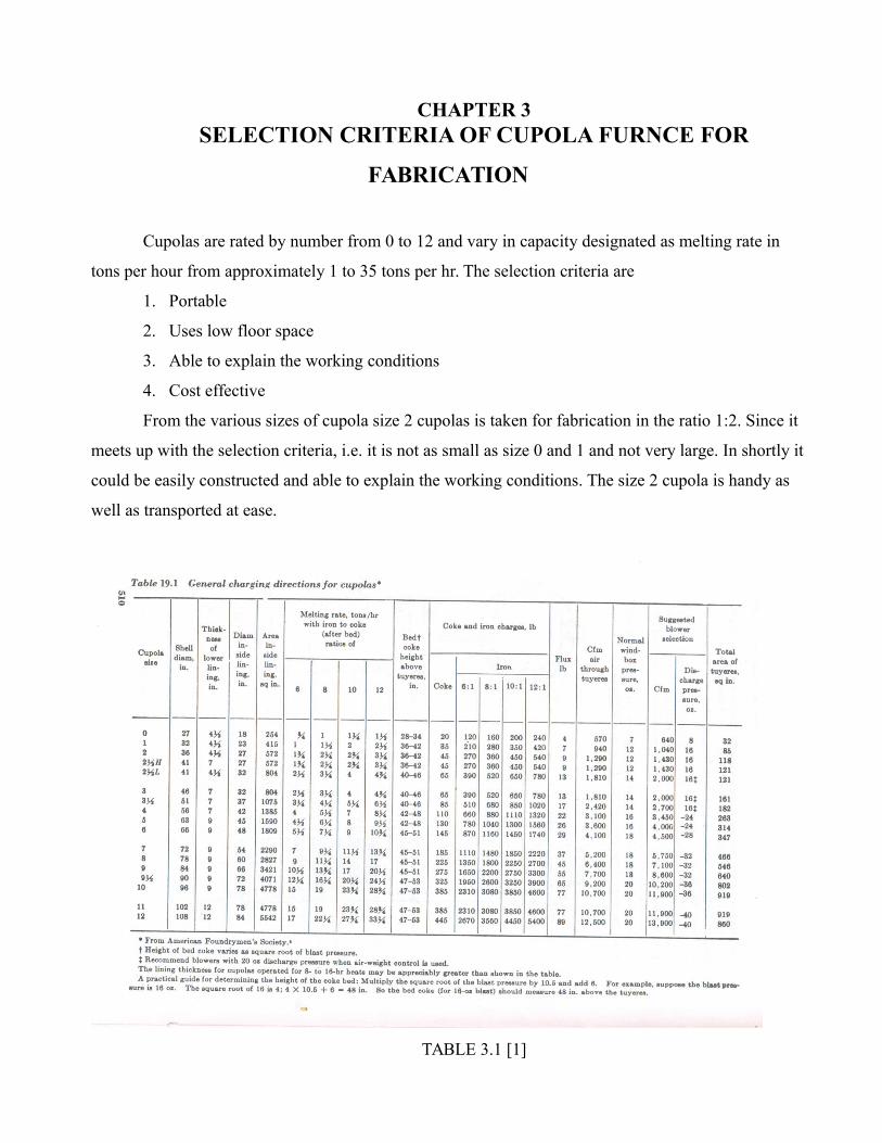
CHAPTER 3SELECTION CRITERIA OF CUPOLA FURNCE FOR
FABRICATION
Cupolas are rated by number from 0 to 12 and vary in capacity designated as melting rate in
tons per hour from approximately 1 to 35 tons per hr. The selection criteria are
1. Portable
2. Uses low floor space
3. Able to explain the working conditions
4. Cost effective
From the various sizes of cupola size 2 cupolas is taken for fabrication in the ratio 1:2. Since it
meets up with the selection criteria, i.e. it is not as small as size 0 and 1 and not very large. In shortly it
could be easily constructed and able to explain the working conditions. The size 2 cupola is handy as
well as transported at ease.
TABLE 3.1 [1]
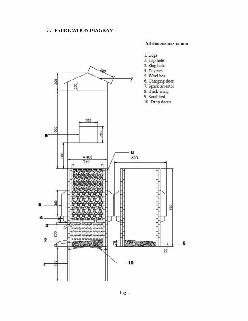
3.1 FABRICATION DIAGRAM
Fig3.1
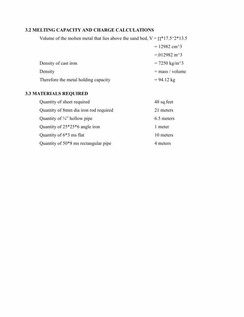
3.2 MELTING CAPACITY AND CHARGE CALCULATIONS
Volume of the molten metal that lies above the sand bed, V = ∏*17.5^2*13.5
= 12982 cm^3
=.012982 m^3
Density of cast iron = 7250 kg/m^3
Density = mass / volume
Therefore the metal holding capacity = 94.12 kg
3.3 MATERIALS REQUIRED
Quantity of sheet required 48 sq.feet
Quantity of 8mm dia iron rod required 21 meters
Quantity of ¾” hollow pipe 6.5 meters
Quantity of 25*25*6 angle iron 1 meter
Quantity of 6*3 ms flat 10 meters
Quantity of 50*8 ms rectangular pipe 4 meters
CHAPTER 4
FABRICATION DETAILS
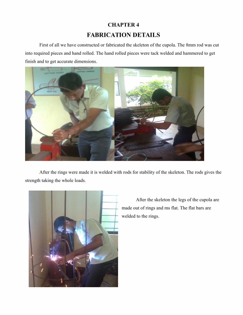
First of all we have constructed or fabricated the skeleton of the cupola. The 8mm rod was cut
into required pieces and hand rolled. The hand rolled pieces were tack welded and hammered to get
finish and to get accurate dimensions.
After the rings were made it is welded with rods for stability of the skeleton. The rods gives the
strength taking the whole loads.
After the skeleton the legs of the cupola are
made out of rings and ms flat. The flat bars are
welded to the rings.
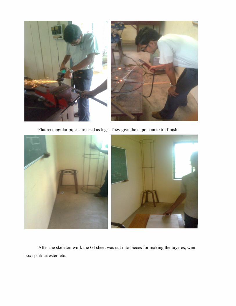
Flat rectangular pipes are used as legs. They give the cupola an extra finish.
After the skeleton work the GI sheet was cut into pieces for making the tuyeres, wind
box,spark arrester, etc.

The GI sheet was hand rolled to the skeleton and the tuyeres and other parts were gas welded
to the main structure. Primer was also coated to the structure. Charging door was also gas cutted to the
structure. The split doors were hinged at the wind box.
Then we made the charging platform and the ladder for accessing the charging platform. The
charging platform needs to be below than the charging doors.
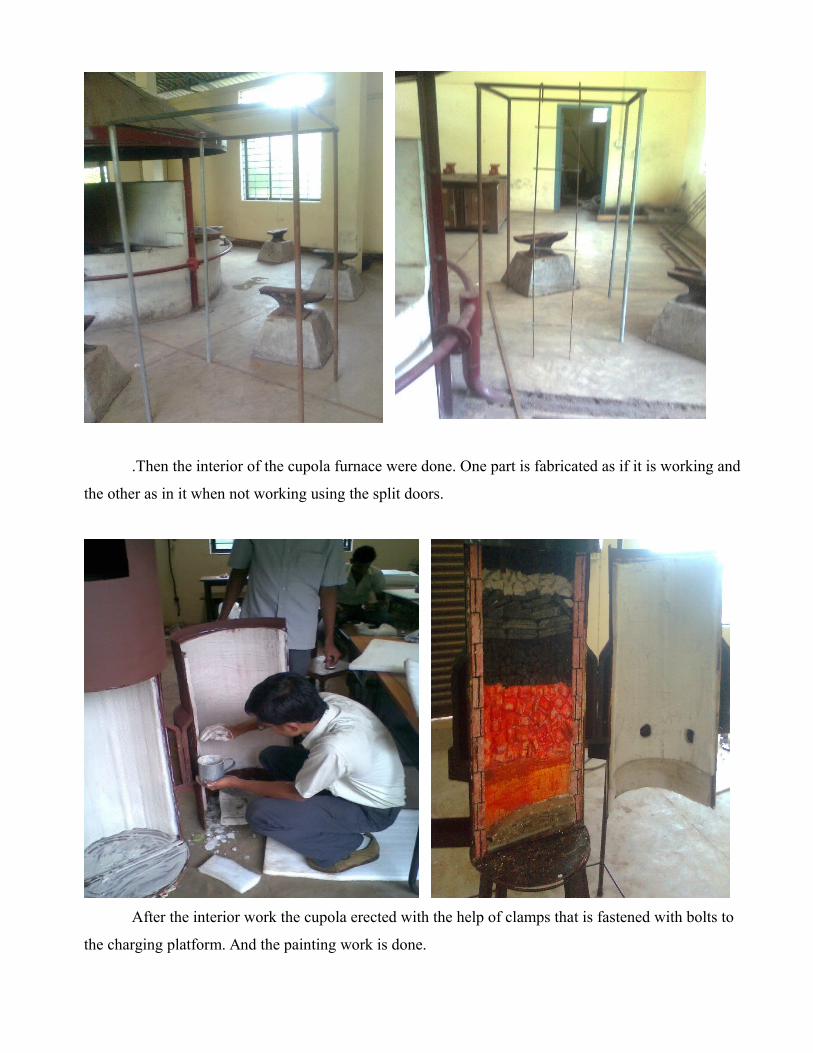
.Then the interior of the cupola furnace were done. One part is fabricated as if it is working and
the other as in it when not working using the split doors.
After the interior work the cupola erected with the help of clamps that is fastened with bolts to
the charging platform. And the painting work is done.


CHAPTER 5
CONCLUSION
The size 2 cupola is fabricated in the ratio 1:2 and is able to explain all the working conditions
as per the international standards.

BIBLIOGRAPHY
[1] Richard W Heine, Carl R Loper and Philip C Rosenthal, Principles of Metal Casting, Second
Edition, Tata McGraw-Hill Publishing Company, 1976
[2] O P Khanna, Foundry Technology, Revised Edition, Dhanpat Rai Publications, 1996
[3] http://en.wikipedia.org/wiki/Cupola_furnace