selected issues of production systems … · selected issues of production systems organisation and...
TRANSCRIPT
Projekt współfinansowany ze środków Unii Europejskiej w ramach Europejskiego Funduszu Społecznego
ROZWÓJ POTENCJAŁU I OFERTY DYDAKTYCZNEJ POLITECHNIKI WROCŁAWSKIEJ
Wrocław University of Technology
Production Management
Jacek Czajka, Kamil Krot, Michał Kuliberda
SELECTED ISSUES OF PRODUCTION
SYSTEMS ORGANISATION AND
COMPUTER AIDED PROCESS
PLANNING Production System OrganisationTechnology
Wrocław 2011
Wrocław University of Technology
Production Management
Jacek Czajka, Kamil Krot, Michał Kuliberda
SELECTED ISSUES OF PRODUCTION
SYSTEMS ORGANISATION AND COMPUTER AIDED PROCESS
PLANNING Production System Organisation
Wrocław 2011

Copyright © by Wrocław University of Technology
Wrocław 2011
Reviewer: Edward Chlebus
ISBN 978-83-62098-17-0
Published by PRINTPAP Łódź, www.printpap.pl
Contents: 1 Introduction .......................................................................................... 5
2 Production organisation – machines allocation ................................... 7
3 Types of production process organisation ........................................... 14
3.1 Linear form of production process organisation ............................... 14
3.2 Cellular form of production process organisation ............................ 16
3.3 Technological form of production process organisation .................. 18
3.4 Layout for immobile items................................................................ 20
3.5 Mixed forms ...................................................................................... 21
4 Group Technology ............................................................................... 22
4.1 Classification and coding of parts ..................................................... 25
4.2 Creation of workcells ........................................................................ 30
4.3 Arrangement of machine tools inside workcell ................................ 35
4.4 Costs as a criterion of process optimisation ...................................... 37
5 Methodology of designing a manufacturing system ............................ 41
6 Designing arrangement of workplaces using computer systems ......... 49
6.1 Designing arrangement of a workplace with presentation in 2D view
................................................................................................................. 52
6.2 Designing arrangement of workplaces with presentation in CAD 3D
system ..................................................................................................... 56
7 Computer systems for simulation of production processes ................. 59
7.1 iGrafx system .................................................................................... 59
7.2 ProModel........................................................................................... 61
8 Methods of optimisation of workplace allocation ............................... 67
8.1 Rank Order Clustering Method ......................................................... 67
8.2 CORELAP method (Computerized Relationship Layout Planning) 69
9 Computer aided processes planning CAPP.......................................... 73
9.1 Variant method.................................................................................. 76
9.2 Generative method ............................................................................ 80
9.2.1 Features in generative process planning ........................................ 81
9.2.2 Forward and backward process planning ....................................... 84
9.2.3 Obtainment of technological features ............................................ 85
3

9.2.4 Expert systems in generative CAPP systems ................................. 87
10 Features in technical production preparation ..................................... 92
10.1 Functional features .......................................................................... 93
10.2 Design features................................................................................ 94
10.3 Technological features .................................................................... 98
10.4 Machining features.......................................................................... 100
10.5 Methods of obtaining technological features .................................. 104
10.5.1 Languages of describing construction form ................................. 105
10.5.2 Designing by features .................................................................. 107
10.5.3 AAG graph methods (Attributed Adjacency Graph) ................... 109
10.5.4 Syntactic pattern recognition ....................................................... 111
10.5.5 Rule-based algorithms – logic approach ...................................... 112
10.5.6 Recognition from neutral format of STEP data exchange ........... 113
11 Knowledge representation methods used in CAPP ........................... 117
11.1 Frame representation ....................................................................... 117
11.2 Rule representation ......................................................................... 119
11.3 Expert systems ................................................................................ 120
11.3.1 Tools for building expert systems ................................................ 123
11.3.2 Shell expert systems ..................................................................... 126
11.3.3 Knowledge processing in rule-based expert systems................... 128
12 Summary ............................................................................................ 134
Bibliography ........................................................................................... 135
4
1 Introduction
Contemporary requirements, with which production companies are
presented, are coercing production in ever-shorter time and at ever-smaller
expense. In order to meet those expectations companies are undertaking
various actions: they improve work organisation, improve employees’
qualifications, improve product quality simultaneously minimising the
amount of defects. One of key areas within an enterprise, requiring
implementation of improvements, is broadly defined manufacturing. For
many years companies have been striving to accelerate realisation of an
entire production process by introducing new solutions to the area of
manufacturing. Those actions comprise i.a. modernisation of machinery,
what allows products to be manufactured faster, of better quality, and often
at smaller cost of production. Apart from or in tandem with production
resources in form of machines, acceleration of manufacturing processes is
achieved by work organisation improvement.
In hereof paper are presented issues related to designing
manufacturing systems taking into account planning of workplaces
allocation (layout). The fundamental task in this area is selection or
modification of equipment in form of workplaces and means of transport. It
is indispensible during that process to take into consideration employed
technologies and appropriate utilisation of surface designated to realise
manufacturing processes.
In chapter 3 are presented types of organisations of production
process considering relations between workplaces.
5
In chapter 4 is presented the concept of Group Technology. Its
features were reviewed and its usefulness in technological process designing
and production process designing was shown.
Chapter 5 contains description of procedure for dealing with design
of workplace allocation. That and following chapters reviewed how those
works can be aided through application of information tools. Tools for
production systems designing were characterised as well as tools for
simulating its operation.
The second part of this paper contains information on the subject of
computer aided technological processes designing with computer tools
applied – systems aiding technological processes planning – CAPP
(Computer Aided Process Planning). The emphasis needs to be put on the
course of manufacturing process as the very base for production system
designing. That is because the course of a manufacturing process determines
transportation routes in accordance with an established list of technological
operations and assigned to them workplaces.
6
2 Production organisation – machines allocation
Investment outlays connected with development of modern production
systems are very high, hence a diverse range of analyses and simulations are
used beforehand of implementation of solutions regarding organisation of a
production system. Those costs can be lowered through an appropriate
choice of the type and number of production devices and their optimum
allocation within a machine shop. That decision process in practice take
involves variant, on numerous occasions repeated solution of issues of the
same kind, until satisfactory results are reached fulfilling predetermined
assumptions. Correct conducting of that process has got also a significant
influence on:
- maintenance costs cutting of production system,
- improvement of machine utilisation rate,
- increase in system efficiency being the result of better machines
allocation and higher transport throughput [1].
Optimisation of machines arrangement belongs to one of the very first
tasks, which should be solved in the preliminary phase of designing a
system. Characteristic for contemporary production systems low level of
inter-operational stocks compels very strict, mutual relations between
machines.
Allocation of production objects is expressed in mutual arrangement
and determination of positioning relative to successive components of a
production process [2]:
- machines and devices,
7
- workplaces,
- workcells,
- departments,
- factory halls and buildings and transport chains.
Numerousness of appraisal criteria for LAYOUT plans renders
impossible to determine and optimum arrangement.
Workplace allocation analysis is conducted when:
- there are changes introduced into the product i.e. e.g.: by improving
effectiveness of existing production or, when a new product is added
to the assortment of already manufactured ones,
- production management techniques are being introduced, such as
e.g.: Just-In-Time or Group Technology,
- allocation of workcells, production lines, departments as well as
entire factories is being planned or improved,
- subject to improvement is flow of materials in production process,
flow of parts, groups of parts, products,
- new equipment, means of transport are ushered in,
- the way of storing is being planned or changed,
- there is a need of presentation and comparison of different allocation
alternatives simultaneously in text form (reports) and graphical.
Problems of designing workcell allocation in manufacturing systems
constitute examples of tasks with multiple solution variants. If there are “$”
workplaces to be allocated in “$” spots, then we get “$!” of possible
configurations [3], [2]. If the number of workplaces and possible spaces of
their localisation are not equal – “n” and “m” correspondingly, where n<m
8

then the number of possible combinations is determined by expression:
m!/(m-n)!. It is less than n!, however it is a lot still. [3], [4].
Problems encountered in practice are far more complicated, because
they take into account additional conditions and constraints resulting from
technology, construction and equipment of a building (e.g. common power
supplies, special foundation, restricted bearing capacity of ceilings), health
and safety conditions (e.g. required distances between workplaces) and
others. Such high number of factors influencing the way of arranging
workcells renders the problem difficult to solve. Coming useful here can be
computer techniques, which allow for presentation of a problem in form of a
model and subject it to different analyses. Computer system can give answer
to the question: which workplaces allocation is optimum for assumed
criteria?
Application of computer techniques in solving problems related to
creation of allocation plans for workplaces holds the following advantages:
- completion of required computations and generation of several
variants of solutions in substantially shorter timeframe compared to
traditional techniques.
- solution of much more complex project tasks in terms of entered
data,
- design process is independent of designer,
- use of a computer leads to obtainment of a solution based solely on
mathematical considerations, which can subsequently be developed
and changed in an objective manner,
- possibility of process optimisation,
9

- possibility of integration with CAD and ERP or PPC and SFC
systems.
In practice, the problem of allocation plan creation is solved by means of a
single or multiple presented below approaches [3], [5]:
- precise mathematical procedures,
- heuristic methods,
- probabilistic methods,
- graph theory.
The goal of those procedures’ functioning depends on applied ways of
expressing relations between allocated workplaces or objects. When
relations are expressed by means of “qualitative coefficients”, they are often
presented by means of “links matrix” where the aim is maximisation of
“closeness” between workplaces. On the other hand when relations between
objects are expressed in “quantitative units” obtained from the matrix of
graph of “FROM_TO”, the aim is minimisation of costs related to transport
of materials, being the result of decreasing distances between departments,
and connected to it flow of materials and unitary transportation costs. In
many cases, especially when designing new facilities, material flow system
remains unknown until workplace allocation plan is constructed. Cost of
transport attributable to a unit of product in this case is accepted (assumed)
with a high approximation, outcome of that action being minimisation of
costs which a product of costs corresponding to flow of materials and
distances. Thus those costs are assumed (with a certain approximation) to be
costs of material transportation. Procedures allowing for obtainment of
solution for all methods presented above are independent both of the way
data was prepared and the method of solution optimisation. Construction of
solution procedures, used during LAYOUT plans creation for the first time,
10
(exclusive of method of optimisation) is based on three fundamental
steps [3]:
- first step: choice of criteria for selecting workplaces, which will be
considered as workplaces to be arranged according to layout
determined on basis of relations between objects,
- second step: distribution of every object to an appropriate place is
done in order to attain a particular aim (minimisation or
maximisation of certain function),
- third step: this step takes place in order to graphically develop the
workplace allocation.
Optimisation procedures of constructed earlier workplace allocation
are considerably diverse between each other due to applied rules of
choosing workplaces in successive steps. Solution acquired on the basis of
optimisation procedures constitutes always one of possible solutions. It is
the result of overlap between effects obtained in “three steps” described
above.
Below are listed exemplary optimisation procedures of workplace
allocation:
- Gavett-Plyter branch and bound method from the group of exact
science methods,
- Hillier-Connors method (HC 66) being a simplified version of
branch and bound method,
- MAT method (Modular Allocation Technique) representing the
group of heuristic methods,
- Schmidgall’s triangles method,
- CORELAP method, using matrixes of functional relations,
11
- CRAFT method, from the group of so-called local optimisation
methods,
- Bender Distribution algorithm, using methods of partially complete
programming.
The choice of workplace allocation optimisation method can be made
after explaining, whether:
- new cells are designed, or are existing cells being changed,
- there are restrictions regarding shape of the surface, across which
workplaces are distributed,
- dimensions of allocated workplaces are varied,
- there are objects of constant localisation.
The basis for selecting a method are the following assumptions:
- when designing new workcells, a new allocation is built from
scratch,
- when modernising existing workcells, an allocation of workplaces is
known, which can be adopted as a preliminary arrangement.
In the first case the most appropriate are going to be step methods,
which do not require knowledge of preliminary allocation, or combination
methods, constituting the conjunction of step and iterative methods. Step
methods are used then to generate preliminary allocations, which are
subsequently improved with iterative methods.
When designing new workcells, task groups are separated, which are
dependent on the degree of freedom in shaping surfaces, across which
workplaces are distributed. Methods having a limited possibility of choosing
a space, precisely determine the structure of workplace localisation spaces
by the shape of surface. Methods with unlimited possibility of choosing
12

spaces, do not determine the shape of the surface. It is obtained as a result,
along with workplaces arrangement. When modernising existing workcells
the shape of surface and structure of workplaces localisation is always a
constraining factor.
13
3 Types of production process organisation
One of the most commonly used classification criteria for types of
organisation of production is taking into account couplings between
elements of a production system. The following types of production system
are distinguished:
- linear form of organisation of production,
- cell form of organisation of production,
- technological form of organisation of production,
- form for items not subject to inter-operational transport,
- mixed solutions.
That classification comprises transport connections between elements
of production system, as well as remaining in a strict relationship with it
inter-operational storing.
3.1 Linear form of production process organisation
Linear form of production process organisation corresponds to
subjective specialisation of production system, where there is similarity with
reference to majority or all technological operations, and their order as well.
In linear form of organisation of production connections between elements
of a production system, plus the way they are allocated are compliant with
the order of performing technological operations.
Example of such allocation of workplaces is shown in fig. 1. Flow of
material is one-way and runs between consecutive workplaces. There are no
14
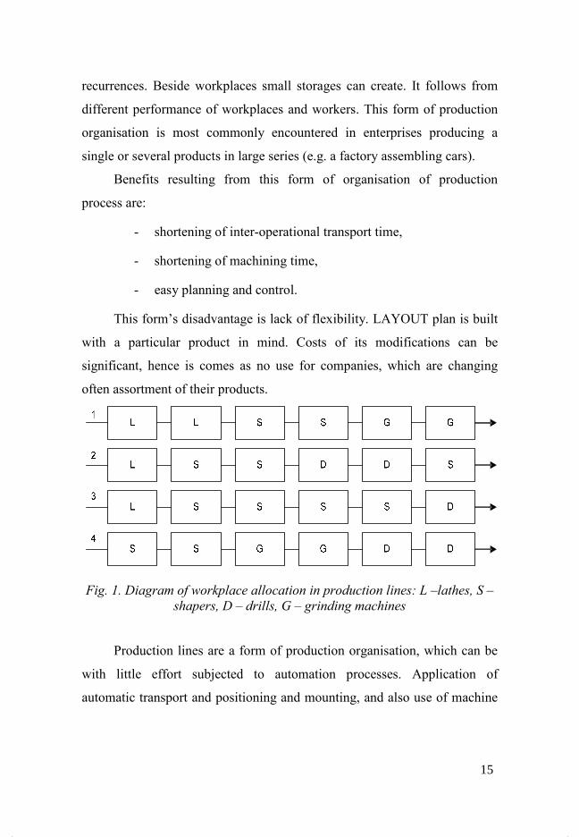
recurrences. Beside workplaces small storages can create. It follows from
different performance of workplaces and workers. This form of production
organisation is most commonly encountered in enterprises producing a
single or several products in large series (e.g. a factory assembling cars).
Benefits resulting from this form of organisation of production
process are:
- shortening of inter-operational transport time,
- shortening of machining time,
- easy planning and control.
This form’s disadvantage is lack of flexibility. LAYOUT plan is built
with a particular product in mind. Costs of its modifications can be
significant, hence is comes as no use for companies, which are changing
often assortment of their products.
Fig. 1. Diagram of workplace allocation in production lines: L –lathes, S –
shapers, D – drills, G – grinding machines
Production lines are a form of production organisation, which can be
with little effort subjected to automation processes. Application of
automatic transport and positioning and mounting, and also use of machine
15
tools working in an automatic cycle is a characteristic trait of automated
production lines.
Grouping workplaces into production lines demonstrates – in
comparison to technological machine allocation, and also subjective in
subjective cells – multiple benefits, which result mainly from higher
constancy in sequence of performing technological operations and also from
straightforward course of machining process. Length of transportation
routes succumbs to significant shortening, especially after connecting
workplaces with means of transport. Work efficiency increases due to
possibility of applying highly specialised machines and devices. Control
over production lines is easier to exercise and it’s easier to prepare a
production plan. Additionally the production floor is better utilised.
Drawback of the aforementioned allocation of workplaces is lack of
full synchronisation of technological operations’ times, what leads to
incomplete utilisation of machines and devices. Admittedly it can be
partially compensated through creation of semi-finished products storages,
however it is possible only in narrow time intervals. Furthermore
manufacturing in production lines is possible only, when production plan
ensures relatively high constancy of technological operations performance
sequence.
3.2 Cellular form of production process organisation
In the cellular structure items, being manufactured in a facility, are
assigned to appropriate groups. Every group of items is manufactured in a
separate workcell. A workcell can be entirely automated when large number
of items of a particular product is required. In case of cellular production,
costs of producing a certain product fall considerably. Those costs are split
16
into fixed (costs related to
labour, material). Cost of manufacturing a product is dependent on the
number of produced items at the identical
same setup of machine tools. The greater the production, the lower the cost
per single product. Cells often adopt shape of the U letter
walking for operating personnel
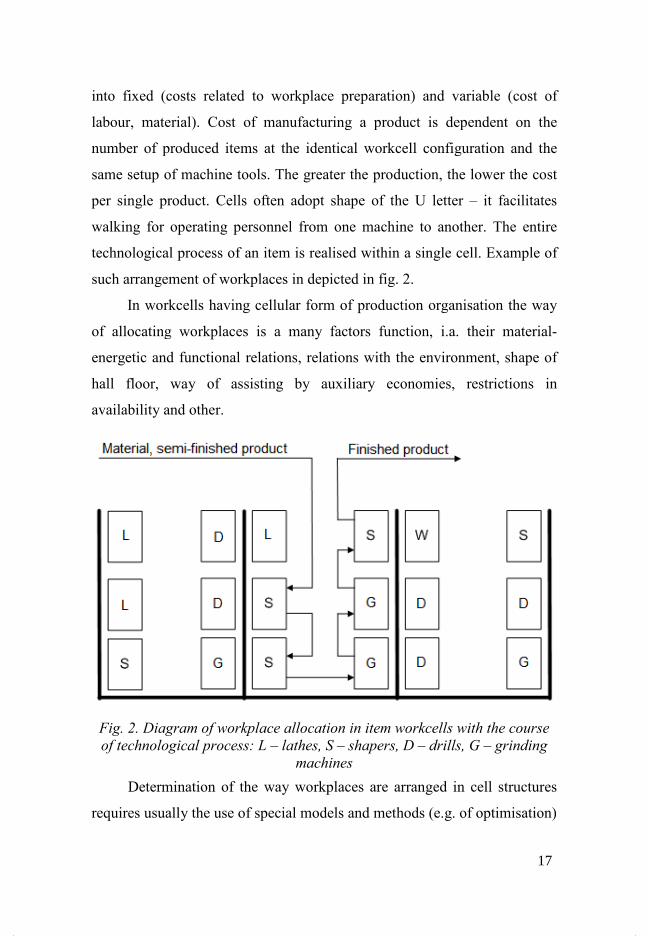
technological process of an item is realised within a single cell. Example of
such arrangement of
In workcell
of allocating
energetic and functional relations, relations with the environment, shape of
hall floor, way of ass
availability and other.
Fig. 2. Diagram of
of technological
Determination of the way
requires usually the use of special models and methods (e.g. of optimisation)
into fixed (costs related to workplace preparation) and variable (cost of
labour, material). Cost of manufacturing a product is dependent on the
number of produced items at the identical workcell configuration and the
same setup of machine tools. The greater the production, the lower the cost
product. Cells often adopt shape of the U letter
walking for operating personnel from one machine to another. The entire
technological process of an item is realised within a single cell. Example of
such arrangement of workplaces in depicted in fig. 2.
workcells having cellular form of production organisation the way
ing workplaces is a many factors function, i.a. their material
energetic and functional relations, relations with the environment, shape of
, way of assisting by auxiliary economies, restrictions in
availability and other.
Diagram of workplace allocation in item workcells with
of technological process: L – lathes, S – shapers, D – drills
machines
Determination of the way workplaces are arranged in cell structures
requires usually the use of special models and methods (e.g. of optimisation)
on) and variable (cost of
labour, material). Cost of manufacturing a product is dependent on the
configuration and the
same setup of machine tools. The greater the production, the lower the cost
product. Cells often adopt shape of the U letter – it facilitates
from one machine to another. The entire
technological process of an item is realised within a single cell. Example of
organisation the way
, i.a. their material-
energetic and functional relations, relations with the environment, shape of
isting by auxiliary economies, restrictions in
allocation in item workcells with the course
drills, G – grinding
are arranged in cell structures
requires usually the use of special models and methods (e.g. of optimisation)
17
3.3 Technological form of production process organisation
Technological form of organisation of production is characterised by
the fact, that in the production system are performed sets of similar
technological operations of different products. Assortment of manufactured
products, is broad and is subjected to constant change. Lack of exact
allocation of tasks to elements of the production system causes, that
relations between them are impermanent and can take their course in
different directions.
In that situation workplaces are grouped together, based on operations
which are performed on them. Departments of lathes, milling machines etc
are created. Technological form of process, offers flexibility, and employees
gradually become experts in particular activities. Example of such allocation
plan of workplaces is shown in fig. 3.
Drawbacks which result from using this form are:
- high costs of inter-operational transport,
- congestion being created during transport,
- complexity in planning and control,
- low efficiency,
- extension of production cycle.
18
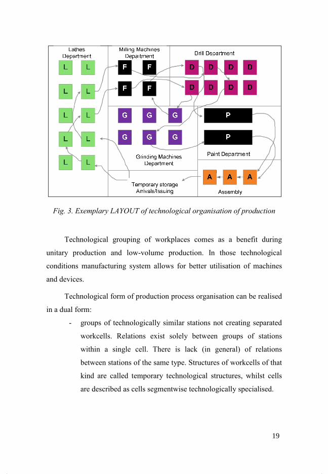
Fig. 3. Exemplary LAYOUT of technological organisation of production
Technological grouping of workplaces comes as a benefit during
unitary production and low-volume production. In those technological
conditions manufacturing system allows for better utilisation of machines
and devices.
Technological form of production process organisation can be realised
in a dual form:
- groups of technologically similar stations not creating separated
workcells. Relations exist solely between groups of stations
within a single cell. There is lack (in general) of relations
between stations of the same type. Structures of workcells of that
kind are called temporary technological structures, whilst cells
are described as cells segmentwise technologically specialised.
T
T
T
T
T
T
T
T
T
T F
F
F
F
W
W
W
W
W
W
W
W
S
S
S
S
S
S
M
M
M M MTemporary storage
Arrivals/Issuing Assembly
Paint department
Lathes
department
Milling machines
department Drills department
Grinding machines
Depatment
19
- groups of stations technologically similar creating separated
workcells. Each of cells realises only a certain part of product’s
technological process e.g. turning, drilling, grinding. In this case
there are relations between workcells, however there is lack (in
general) of relations between stations within a single cell.
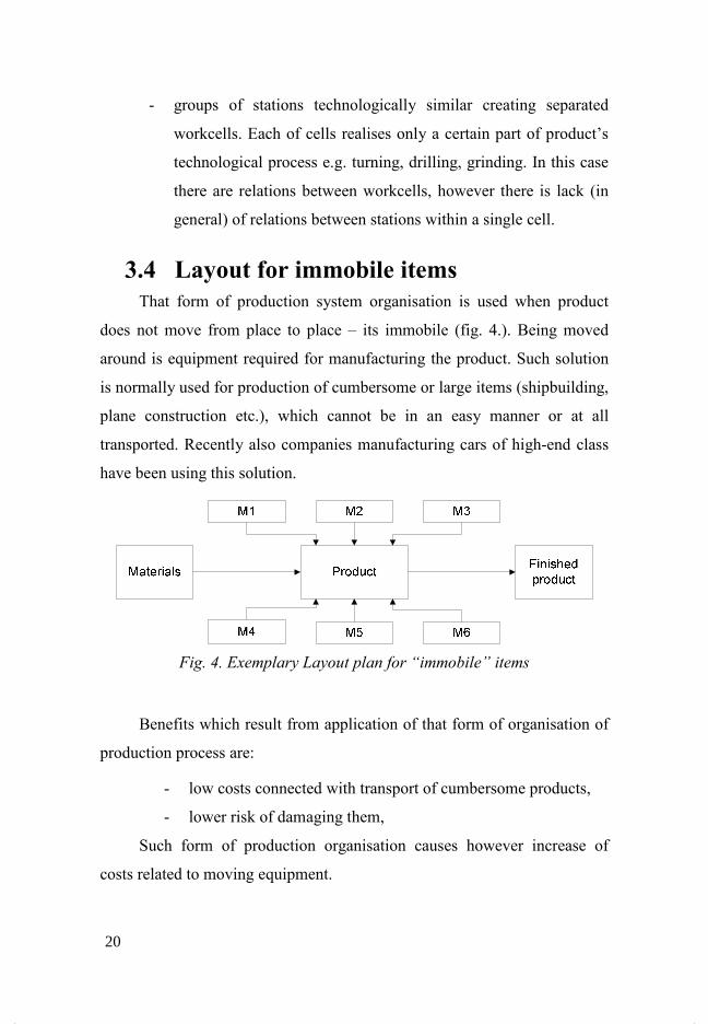
3.4 Layout for immobile items That form of production system organisation is used when product
does not move from place to place – its immobile (fig. 4.). Being moved
around is equipment required for manufacturing the product. Such solution
is normally used for production of cumbersome or large items (shipbuilding,
plane construction etc.), which cannot be in an easy manner or at all
transported. Recently also companies manufacturing cars of high-end class
have been using this solution.
Fig. 4. Exemplary Layout plan for “immobile” items
Benefits which result from application of that form of organisation of
production process are:
- low costs connected with transport of cumbersome products,
- lower risk of damaging them,
Such form of production organisation causes however increase of
costs related to moving equipment.
20

3.5 Mixed forms
Not all companies are capable of adopting only one type of a
LAYOUT plan. Along with enterprise’s development grows the diversity
and quantity of manufactured products. Example of mixed plan of
production organisation is shown in fig. 5.
L D
D
L
D
L
S
L
S D
M
L
D S
L
L L
L
Fig. 5. Mixed form of organisation of production
Unfortunately none of presented above types of LAYOUT plans is
completely capable of satisfying company’s demands. In that case mixed
forms are being used. There are products, for which cell LAYOUT is used,
for others linear.
21
4 Group Technology
Group Technology is such a philosophy of management, which is
aimed at grouping products of similar pattern or of similar technological
process [3], [6], [7], [8], [9]. Manufacturing in workcells can be defined as
application of group technology, where machines are grouped together
depending on requirements set by technologies of items produced there.
Main objective of applying Group Technology is simultaneous organisation
of machines in workcells and parts technologically similar into groups in
order to minimise the route, which is covered inside a workcell. Analysis of
arrangement of machines inside a cell has to lead to reduction of costs
related to transport of inner and intercellular material.
Amongst fundamental advantages of Group Technology one has to include
[10], [11], [12], [13]:
• decreasing of transport operations number– instead of dividing
available equipment into departments conducting one type of processing, it
is possible to divide available departments in accordance with groups of
parts being machined within them. Each of departments becomes an
independent cell capable of performing all or majority of operations
requisite, in a given product family. It results in parts being produced in
shorter time and within one department and it is not necessary to transport
machined parts between other cells. It simplifies flow of materials and
products processed by the manufacturing system.
• shortening of set-up times and decrease of costs related to tools
necessary for machining – due to machining of similar products being
conducted, used tools are standard ones. It entails also reduction of the set-
up time.
22

• decreasing of all costs related to preparation of production – if
a need arises of designing and subsequently manufacturing new products,
the product is placed in the group of parts technologically similar. At that
point there is only necessity of modifying already existing production plans
and instrumentation. It shortens the process of preparing production.
• decrease of inter-operational stock,
• increase of crew’s satisfaction from the work performed,
• variable production plan,
• possibility of flexible utilisation of machine tools temporarily under
lesser load,
• flexibility of technological routes,
• possibility of machined parts’ recurrence,
• susceptibility to computer aided automation,
• integration at the stage of production preparation with processes of
control, transport, storing.
• it constitutes basis for designing and maintaining computer aided
manufacturing systems (FMS, CIM/CAM etc.).
Advantages of Group Technology are also visible in own-cost
accounting and price formulation, internal and external settlements, service
of spare parts. Under conditions of free-market economy the existence of
production organisation without employing classification of parts and
assemblies becomes impossible. Such approach induces application of an
appropriate allocation of machines and devices at the production floor.
Group Technology requires a greater assortment and magnitude of
production equipment. Each of machine tools of a production system with
23
implemented Group Technology needs to be self-sufficient in terms of
instrumentation, what frequently causes duplication of equipment. The
quantity of equipment required when using Group Technology also
increases.
The main difference between traditional setting of machine tools in a
generic system and in a machining cell, is that machines are set up and
grouped together. In generic setting of machine tools, machines are grouped
according to the type of machine tools (i.e. separately lathes, milling
machines, drills, grinding machines etc.)
A machining cell is constituted by a set of workplaces intended for
manufacturing different parts of similar technological processes. The rule of
organising a machining cell is to manufacture “ready-made” items, therefore
in a cell apart from machine tools there are stations for induction hardening,
stations for manual machining, control, and seldom at the beginning of a
cell are placed forging presses, machines for centrifugal casting etc. [14].
In the processes of designing the organisational concept of production
according to Group Technology helps to classify and code parts on the basis
of their geometrical properties and other similarities. Group Technology is
often used in the process of designing products, because a product is
classified and coded there, allowing for utilisation of those codes by
computer systems. Thanks to that, a technologist can find the appropriate
database for an already existing product and can use it for designing a new
part of similar utility and geometrical traits [3], [15], [4].
In the manufacturing process Group Technology focuses on grouping
similar technological operations, similar tools and procedures of machine
tooling, and also similar methods of transporting and storing. Produced
parts, although can look differently, in reality are subject to the same
production process. Application of Group Technology is based on idea of
24
classifying manufactured parts into families. Thanks to identification and
grouping of parts into families, simplification and standardisation of
production processes of parts from the same family can be achieved.
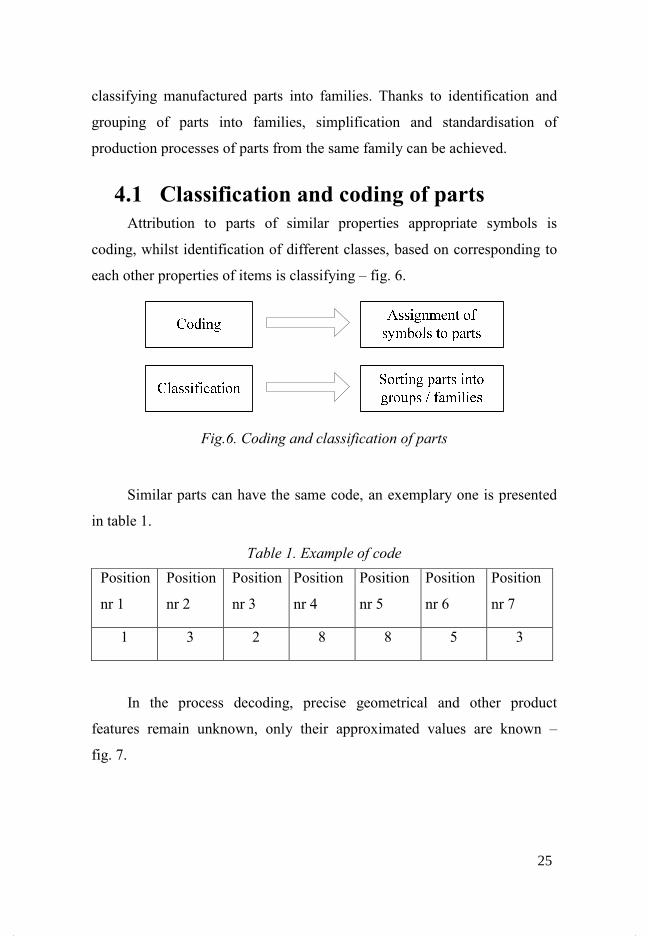
4.1 Classification and coding of parts Attribution to parts of similar properties appropriate symbols is
coding, whilst identification of different classes, based on corresponding to
each other properties of items is classifying – fig. 6.
Fig.6. Coding and classification of parts
Similar parts can have the same code, an exemplary one is presented
in table 1.
Table 1. Example of code
Position
nr 1
Position
nr 2
Position
nr 3
Position
nr 4
Position
nr 5
Position
nr 6
Position
nr 7
1 3 2 8 8 5 3
In the process decoding, precise geometrical and other product
features remain unknown, only their approximated values are known –
fig. 7.
25
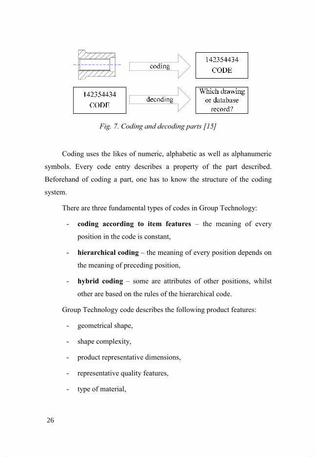
Fig. 7. Coding and decoding parts [15]
Coding uses the likes of numeric, alphabetic as well as alphanumeric
symbols. Every code entry describes a property of the part described.
Beforehand of coding a part, one has to know the structure of the coding
system.
There are three fundamental types of codes in Group Technology:
- coding according to item features – the meaning of every
position in the code is constant,
- hierarchical coding – the meaning of every position depends on
the meaning of preceding position,
- hybrid coding – some are attributes of other positions, whilst
other are based on the rules of the hierarchical code.
Group Technology code describes the following product features:
- geometrical shape,
- shape complexity,
- product representative dimensions,
- representative quality features,
- type of material,
26

- manufacturing technology,
- main application.
Hierarchical code is based on the tree structure. In case of codes of chain
structure for representing information on a part, matrixes are used. Hybrid
structure combines two of above methods using their most functional
features fig. 8 [16].
Fig. 8. Structures of codes used in Group Technology [16]
Thus far many classification and coding systems have been developed,
chronological specification of more important ones is presented in the
table 2 [17].
A hierarchical structure A chain structure
A hybrid structure
27
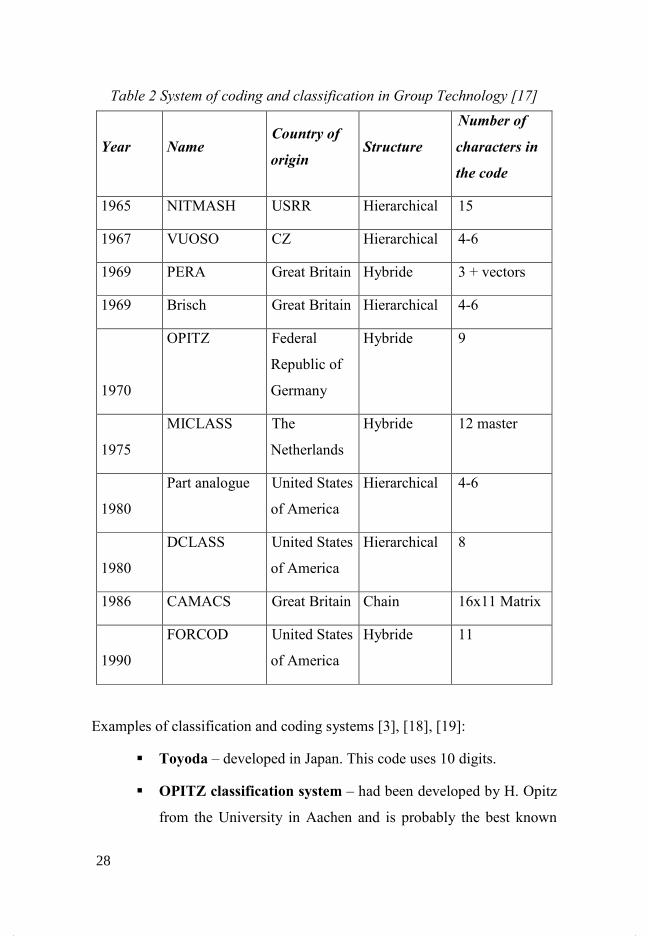
Table 2 System of coding and classification in Group Technology [17]
Year �ame Country of
origin Structure
�umber of
characters in
the code
1965 NITMASH USRR Hierarchical 15
1967 VUOSO CZ Hierarchical 4-6
1969 PERA Great Britain Hybride 3 + vectors
1969 Brisch Great Britain Hierarchical 4-6
1970
OPITZ Federal
Republic of
Germany
Hybride 9
1975
MICLASS The
Netherlands
Hybride 12 master
1980
Part analogue United States
of America
Hierarchical 4-6
1980
DCLASS United States
of America
Hierarchical 8
1986 CAMACS Great Britain Chain 16x11 Matrix
1990
FORCOD United States
of America
Hybride 11
Examples of classification and coding systems [3], [18], [19]:
� Toyoda – developed in Japan. This code uses 10 digits.
� OPITZ classification system – had been developed by H. Opitz
from the University in Aachen and is probably the best known
28

system of classification and coding. The OPITZ system uses
decimal, hybrid code. The base code composes of nine
characters, which can be expanded with next four characters (e.g.
12345 6789 ABCD).
� CODE System is part of classification and coding system
developed by American company Manufacturing Data System,
Inc. It is a hex code, constructed out of eight characters. Each
character can have sixteen different values, which are used for
product properties description.
� MICLASS System is a hybrid code, composed of twelve
characters.
� DCLASS Code is a decimal code, built out of eight characters
divided into five segments.
� Tekla – developed in Norway. Constructed out of 12 digits.
� -ITMASH – developed in USSR. Hierarchical coding.
� Brisch – developed in Great Britain. Computer system without a
constant code structure.
Using classification and coding systems yields the following
benefits [3]:
� Accelerates design process. When new products are being
designed, which are similar to products designed earlier data
saved in database could be accessed under condition, that the
product was appropriately coded earlier. Through modifying
data, documentation for a new product can be swiftly obtained.
Such action to a great extent reduces costs related to product
preparation time for production.
29

� Accelerates the process of creating technological
documentation. Technological plan describes the order of
operations, to which product must be subjected and in what
machines those operations need to be performed. The order of
conducting those operations depends on two factors:
a) technological requirements (order of performing an
operation before others),
b) possibility of performing individual operations in
appropriate, available machines.
Designing a technological process is a tall order, but
thanks to application of coding and classification systems it can
be simplified. A technologist creating technological process for
a new product can use an already existent project for a similar
product.
� Facilitates production scheduling. By appropriate production
designing we can shorten the reset and tooling times of
machines, what allows for effective utilisation of machines and
increase in production efficiency.
4.2 Creation of workcells The fundamental step during implementation of cellular form of
organisation of production is identification of appropriate workcells. Having
the specification of all parts produced (knowing their technological process,
flow of material during production, volume of production batch, setting time
of machines tools, times and estimated annual demand) and available
machinery, parts can be classified into families, and planning of
30
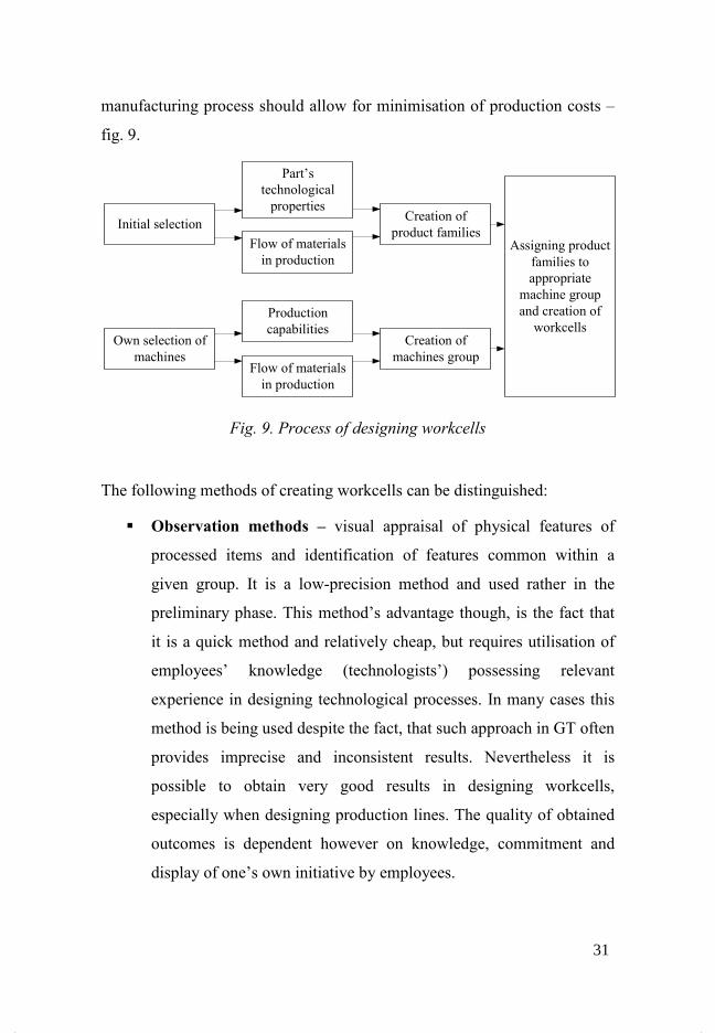
manufacturing process should allow for minimisation of production costs –
fig. 9.
Fig. 9. Process of designing workcells
The following methods of creating workcells can be distinguished:
� Observation methods – visual appraisal of physical features of
processed items and identification of features common within a
given group. It is a low-precision method and used rather in the
preliminary phase. This method’s advantage though, is the fact that
it is a quick method and relatively cheap, but requires utilisation of
employees’ knowledge (technologists’) possessing relevant
experience in designing technological processes. In many cases this
method is being used despite the fact, that such approach in GT often
provides imprecise and inconsistent results. Nevertheless it is
possible to obtain very good results in designing workcells,
especially when designing production lines. The quality of obtained
outcomes is dependent however on knowledge, commitment and
display of one’s own initiative by employees.
Initial selection
Own selection of machines
Part’s technological properties
Flow of materials in production
Production capabilities
Flow of materials in production
Creation of product families
Creation of machines group
Assigning product families to appropriate
machine group and creation of
workcells
31
� Classification and coding of products. Workcell designing by
means classification and coding systems requires completion of
three steps.
First step is identification of products, by determination of
category of products sharing common technological features.
Properties and dimensions of individual categories are considered.
Second step is alphanumeric coding of individual parts, and
that code is represented by information about the coded product.
Third step is classification of products into product families,
which have similar technological properties, by means of using
coded data on designing and technological properties of individual
parts.
It is important, that the codes identified parts in a manner allowing
for identification and obtainment of coherent data. In those systems a
special code is attributed to particular features of a part depending on
e.g. is that part cylindrical or conical, is it threaded, has it got any
holes, is the heat treating required etc. This part of the production
preparation process demands paying loads of attention and sacrificed
time in order to precisely classify all parts. Conducting research into
features characteristic for machining processes or their technically-
constructional parameters are underling the classification and coding
methods. Disadvantage of those methods is the fact, that creation of
codebase for products entails time outlays and is labour-intensive.
Moreover code often provides limited information about the product
construction, as well as about the ways of its manufacturing, hence
there is a need for constant, active engagement from experienced
employees in the process of designing and manufacturing of a
32

product. For creation of workcells one can use an already existing in
enterprise classification and coding system. In case of lack of it, its
introduction, exclusively for designing workcells is unprofitable,
because there are other methods of designing workcells which are
less time and cost-intensive.
� Production flow analysis – determines simultaneously families of
parts and groups of machines though material flow analysis in
production process. Production flow analysis groups into families
products, having similar technological processes and requiring
machining in the same machines, and also requiring combination of
those machines into a machining cell. Method of production process
course analysis concentrates on similarities (conformity) in
technological operations. As base material for analysis are used data
derived from technological and planning documentation. The
analysis can be divided into four fundamental stages [20]:
- construction of databases: accumulation of data, combination
into sets, items subject to analysis from the planned production
process’s point of view, coded description of every element.
- element sorting: creation of subsets according to conformity of
technological operations.
- visualisation of production process course: graphical
representation of outcomes of sorting operation.
- parts grouping.
Techniques of production flow analysis have got the following
advantages:
33

- allow for designing a machining cell quicker and at relatively
lower effort than if used was classification and coding
system,
- because production flow analysis is based on material flow in
production process, those techniques are focused solely on
current production methods, using existing machinery and
tool system,
- production flow analysis provides production reorganisation
and obtainment of benefits resulting from cellular form of
organisation of production process at low outlay of
investment costs.
In the initial stage of analysis a matrix of Mx� is formed, where:
- M – number of machines,
- � – number of parts produced.
If the matrix is of small proportions, products requiring similar
technological operations, can be grouped together, as a result of manual
sorting of rows and columns. If the Machines-Parts matrix is larger, then for
sorting the matrix are used the following methods:
- Rank Order Clustering method,
- Bonding Energy (BE) method,
- Row and Column Marking method,
- methods based on computing Relationship Coefficient (RC),
- matrix method.
In order to obtain good results of conducted analysis, one should be
acquainted with precise flow of materials in production process for every
manufactured part. Some products might not match a family, because they
34
require a special operation. In order to make decision about adding an
additional machine, an additional analysis is required.
4.3 Arrangement of machine tools inside workcell
In previous chapter methods of creating a workcell were presented. As
a result of calculations the number of cells and allocated to them stations are
obtained. The next step of designing such LAYOUT plan is to solve the
problem of station arrangement inside every cell.
Wherever machines in quantity of 1 to 15 units are grouped into a
workcell, the U-shaped workcell is recommended, presented in fig. 10.
Machines were arranged as follows, in order to achieve very tangible
objectives such as improvement of conditions of their service and possibility
of high automation for that matter. U-shaped workcell holds numerous
advantages. It provides high flexibility, and employees operating it are
prepared to perform a broader range of tasks. Those tasks may change and
their quantity may decrease and increase while maintaining the core
production attributed to the given cell. Employees are responsible for more
than one machine (pairing of machines), therefore usefulness of employees
ceases to be narrowed down to only operate a single machine. Close contact
and cooperation between employees in U-shaped cells renders productivity
to increase at lower rate of downtimes (idleness), prevents reduction in
quality, decreases level of inter-operational stocks and value of production
in-progress.
35
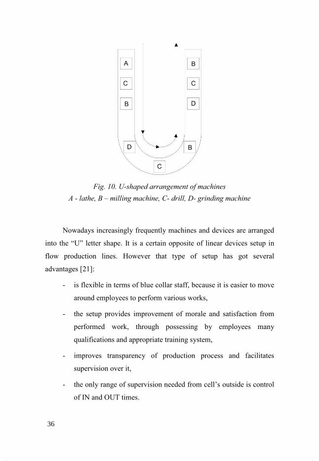
Fig. 10. U-shaped arrangement of machines
A - lathe, B – milling machine, C- drill, D- grinding machine
Nowadays increasingly frequently machines and devices are arranged
into the “U” letter shape. It is a certain opposite of linear devices setup in
flow production lines. However that type of setup has got several
advantages [21]:
- is flexible in terms of blue collar staff, because it is easier to move
around employees to perform various works,
- the setup provides improvement of morale and satisfaction from
performed work, through possessing by employees many
qualifications and appropriate training system,
- improves transparency of production process and facilitates
supervision over it,
- the only range of supervision needed from cell’s outside is control
of IN and OUT times.
36

- control over flow inside the cell is performed by foreman or cell’s
employees,
- utilisation of Group Technology in U-shaped cells, finds its
reflection in form of implementation of the JIT concept.
Figure 10 presents a U-shaped workcell. Material necessary for
manufacturing the product enters the cell, progresses through it and leaves
the cell in form of a finished product.
4.4 Costs as a criterion of process optimisation
In this chapter is presented one of the most important aspects of an
enterprise’s economic activity, namely analysis of costs related to
production process and influence of allocation of workplaces on level of
costs. It is an immensely vital factor, which needs to be precisely analysed
before initiating construction of manufacturing system.
Manufacturing system should be created in a fashion ensuring a
comprehensive and constant surveillance in real time both over flow of
information and materials necessary for conducting the production process.
One of the most prominent issues when designing a workcell is
grouping of machine tools and machined parts. The hitherto approach
towards this matter didn’t take into account such essential factors as the
order of technological operations and required production batch size. New
methods of organisation of production do take into account the
technological process (order of technological operations) and arrangement
of cooperating stations as factors directly influencing costs of material
transportation within a workcell, as well as between workcells.
Grouping of machines focuses on actions aimed at [22]:
37

- creation of machining cells, where items are manufactured
“ready-made”,
- determination of plain flow of parts processed by a workcell,
- elimination of “recurrences” and intersections of part
machining routes,
- minimisation of investment outlays related to purchases of
machine tools of the same kind,
- obtainment of appropriate degree of machine utilisation,
- obtainment of appropriate production system efficiency,
One needs to pay attention to the fact, that the order of technological
operations is directly connected with costs of transportation. In strict
relation with that issue remains also the volume of production batch related
to production in-progress stock and frozen capital. Hence the methods of
allocation and grouping of workplaces should also take into account those
factors in particular and should provide an answer to the question of how to
organise the manufacturing process in order to lower costs of transportation
and costs related to production in-progress stocks.
Analysis of costs related to flow of materials with reference to
creation of workcells is based on several assumptions [22]:
- costs of transport between cells are connected with the
physical displacement of parts, loading and unloading and
coordination of a cell’s work. The perfect situation would be
manufacturing “read-made” parts within the confines of a
given cell.
- costs of transportation inside a cell are dependent on the
magnitude of the batch machined and allocation of stations
38
within the cell. They are also related with the direction of flow
of parts through the cell, recurrences and intersections of
flows. Those last two factors in particular significantly
increase the costs of intracellular transport.
- costs of omitting a workplace incurred when some parts are
not machined in all machines within a given cell. It contributes
to process delays.
The magnitude of the batch subjected to machining plays also an
important role in determination of manufacturing costs. Obvious is the fact
of increasing transportation costs with the increase of the quantity of parts
processed in a given batch.
In an ideal system of cellular form of production there is no flow of
material between cells, but in reality it is a very difficult task to form
machine groups in such a way, that there was no flow of material between
them. Bearing in mind that practical constraint, the analysis should try to
formulate such machine groups, which would minimise the intracellular
flow of material. Also an important task is minimisation of costs related to
intercellular transport of material, and that requires designing LAYOUT
plans for each of cells. One of possible ways is firstly identification of
workcells and parts, which are going to be manufactured there, secondly
LAYOUT of machines in workcells has to be designed and the LAYOUT of
the cell itself as well.
The profitability of purchasing an additional machine for a workcell
needs to be frequently considered, in order for the part manufactured to be
produced in that cell from start to finish, or is it rather more profitable to
e.g. automate the transport between two cells, where that part is being
produced, or perhaps create a special buffer, from which materials for
production of a given product are going to be collected. An additional
39
machine tool of the same kind can also be purchased, in order for the part to
be completely machined within a single cell.
Allocation of machines in the cell and the cell’s itself can be planned
in such a way, that machine tool was a constituent of both cells. In that
manner we avoid doubling of machines of the same kind.
Other factors which need to be taken into account are:
- size of inter-operational stock,
- machine’s depreciation,
- cost related to the time of setting up the machine.
If those costs are taken into account during designing of workcells and
attributing part families to those cells, the end result not only will allow for
better control over production, but also will considerably decrease costs of
production.
Improvements of inner transport provide the fastest and the cheapest
route to better the profitability. Thus one has to strive for reduction of
transport operations, which increase the process cost. When solving
problems connected to transport one need to take into account the design of
workplace allocation structure and data related to the project.
40
5 Methodology of designing a
manufacturing system
Methodology of designing allocation of workplaces presents the
diagram in fig. 11. The course of work was divided into stages. Their
detailed description in located below. Subjects of designing in presented
methodology are production-subjective cells. Manufactured in these cells
products have got similar or different technological routes. It determines the
presence of complex coupling network between elements of production
system i.e. occurrence of recurrences and workplace skipping. Presented
methodology is applicable in designing new production systems or
reconstruction of existing ones.
STAGE 1 Collection of necessary data and definition of design task
At the first stage gathering of information takes place, which is
necessary for defining the design task. The square one here is the course of
manufacturing processes. A technologist developing the technological
process defines technological operations to which apart from tools,
instruments, parameters, description, sketch and norm he also attributes the
workplace. In that manner he determines the technological route for a given
process. The material is passed between stations until completion of a
finished product. All those activities can be computer aided.
41

Fig. 11. Methodology of designing workplace allocation
Production system designing requires at least two-level approach,
where two fundamental tasks are solved consecutively [1]:
- selection of hardware equipment in terms of used technologies,
42
- allocation of chosen machines in production departments.
Additionally a range of essential data needs to be garnered such as [21]:
- organisational structure of enterprise,
- type of production system,
- multiplicity of staff and their qualifications,
- dimensioned sketch of the surface available, precise scaled
drawings of surfaces’ projections, thickness of buttresses,
socles, dimensions of juts projecting from walls, switchboards,
fuse boxes etc.
- localisation of existing installations or permanent
constructions,
- deployment of existing office spaces, sanitarian areas etc.,
- volume of production, both current and enclosed in enterprise
development strategy,
- type of technologies used, performed operations, their
description, sequence and normative execution times, with
indication to any operations of hazardous or special character,
- specification of equipment intended for performing operations
together with specification of concomitant special
requirements, electric power, devices of repair sets,
safeguarding etc.,
- number and type of transport operations of material between
workplaces, (it’s convenient to aggregate that information in
form of oriented matrix of transport relationships),
43

- lead times, aging times, stabilisation times etc., during the
manufacturing process,
- quantities and sizes of operational stocks at each workplace,
- dimensions of main storages, finished products storages, are
dependent on used delivery system and used dispersal ranges,
- required communication links and emergency exits,
- any special requirements, for example burglar alarms, alarm
system etc.,
- spare devices or premises which need to be included in the
plan.
All the above information required are perceived as necessary prior to
commencing workplace arrangement designing. Obviously the
characteristics of every production or services process require an
individualised approach.
STAGE 2 Selection of optimisation criteria
The literature concerning the subject matter lists a range of available
criteria of correct allocation of objects and as far as allocation techniques
regard organisation of production or areas of examining work methods, the
allocation process itself has got a creative character, impossible to conclude
in a final and irrevocable manner, where experience plays the biggest part.
Below are listed several most important criteria, which ought to be fulfilled
by a given production structure. They are [21]:
Maximum flexibility: giving possibility of easier modification
depending on changing circumstances. One should especially pay attention
to an object’s tooling to be sufficiently in working order and easily
accessible installations.
44

Maximum interdependence: delivery and collection processes should
be organised, so that they would provide maximum satisfaction of
cooperating departments’ needs, arrangement should be visible also from
the global, not only local point of view.
Maximum space utilisation: production organisation should be treated
as three-dimensional objects, wiring, pipelines and other installations
requisite in the production process should be led over the heads of
employees, if we use cotemporary storing devices we can fulfil that
postulate at ease.
Maximum transparency: one needs to strive for provision of constant
visual control over entire personnel and conducted processes. It is often
quite difficult to fulfil this criterion, especially in situations, when already
existent objects are taken over.
Maximum accessibility: any operational and service points should be
easily accessible, if obstruction of repair service or maintenance points is
unavoidable then one needs to aim at installing a mobile device.
Minimum distance: any displacements should be made only when it is
necessary and take place at the shortest distance possible. Transport
operations are only increasing costs without adding any value.
Minimum transhipments: if transhipments cannot be avoided, then
their number has to be reduced.
Minimum inconvenience: bad lighting conditions, draughts, excessive
sun exposure, noise, vibrations – all those phenomena need to have actions
taken against them and their influence on people minimised.
Inherent safety: none of employees can be exposed to any form of
danger resulting from incorrectly organised production system.
45
Maximum protection: protection against fire, dampness, heart attack
etc. they should be taken into account already at the stage of allocation
designing.
Effective courses of processes: material stream flows in production
process should not intersect with each other, one-way flow through objects
should be maintained, arrangement contributing against that notion leads to
serious difficulties, sometimes to chaos in organisation.
Identification with the workplace: wherever it is possible, an employee
should have his workspace allocated.
Most commonly used in designing workplace allocation is the savings
code of conduct [23]. It means searching for solutions guaranteeing a
particular degree of goal realisation (e.g. determined production tasks) at
minimum construction and system maintenance outlays. Hence the most
frequently used criteria of solution’s assessment are transportation costs,
values of ratios describing transportation tasks (length of transportation
routes, transported volumes etc.), cost of workplaces’ installation, costs of
production floor and other.
STAGE 3 Construction of mathematical model.
At the third stage, description of the task being solved takes place in
form of a mathematical model. There are multiple mathematical models of
the allocation task. Use of a particular one depends on specifics of the task
being solved [23]: type of production structure and coupling network,
number and type of constraints, and also assumed optimisation criterion.
Last of aforementioned factors decides about the form of objective function,
being the main element of a task’s mathematical model.
46
Predominantly formulated and solved are tasks with a single
optimisation criterion. The necessity of fulfilling many, often opposing
goals, causes allocation tasks to have to be formulated as multi-criteria.
STAGE 4 Task solution.
At the fourth stage the posed task is solved be means of optimisation
methods. Selection of the method of solving the allocation task is
determined by many factors. The main one being the mathematical form of
the task.
STAGE 5 Construction of theoretical LAYOUT plan.
Based on results obtained from solving the task (Stage 4) a theoretical
LAYOUT plan is constructed in form of a graphical model. Due to existing
restrictions, which were not taken into account in the mathematical model
many variants of theoretical arrangement of workplaces can be developed.
The usefulness assessment of individual solutions will take place at
subsequent stages.
In case of unfavourable appraisal there is possibility of reverting to
preceding stages of the methodology, in order to e.g. reformulate the task
and its repeated solution. It may also turn out, that the only radical manner
of obtaining an acceptable solution is to improve the flow of material
through changes in production structure.
STAGE 6 Construction of a detailed LAYOUT plan.
Based on a chosen, real variant of theoretical allocation a detailed
design of workplaces’ arrangement is developed (in several variants). To
build detailed allocation plans one can use graphical editors.
STAGE 7 Construction of simulation models and running the simulation
and optimisation of production process.
47
By simulation and optimisation of production process we understand
carrying out various tests upon a model, under different scenarios, where we
determine particular optimisation criteria of obtaining satisfactory to us
results, for precisely determined values of factors influencing the model’s
behaviour.
Simulation is a technique serving as an imitation of an entire system’s
functioning or just imitating certain situations (economic, military,
mechanical, etc.) through use of appropriate models or devices in order to
obtain information, or for didactical reasons. [24]. Computer simulation
facilitates analysis and optimisation of a newly designed process prior to its
implementation, thanks to which we avoid costs related to system
implementation, which could have been incorrectly designed.
48
6 Designing arrangement of
workplaces using computer
systems
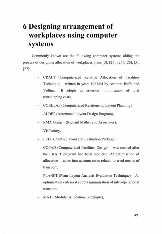
Commonly known are the following computer systems aiding the
process of designing allocation of workplaces plans [3], [21], [25], [26], [5],
[27]:
- CRAFT (Computerized Relative Allocation of Facilities
Technique) – written in years 1963/64 by Armour, Buffe and
Vollman. It adopts as criterion minimisation of total
transhipping costs,
- CORELAP (Computerized Relationship Layout Planning),
- ALDEP (Automated Layout Design Program),
- RMA Comp 1 (Richard Mather and Associates),
- VisFactory,
- PREP (Plant Relayout and Evaluation Package),
- COFAD (Computerized Facilities Design) – was created after
the CRAFT program had been modified. At optimisation of
allocation it takes into account costs related to used means of
transport,
- PLANET (Plant Layout Analysis Evaluation Technique) – As
optimisation criteria it adopts minimisation of inter-operational
transport,
- MAT ( Modular Allocation Technique),
49
- BLOCKPLAN,
- EON Planner,
- Delmia QUEST and others.
Some of those solutions are obsolete and offer a very limited
functionality. They operate in text mode and as the result of optimisation
they present only the mutual arrangement of objects. The obtained result is
very simplified and requires further analyses. Contemporary systems work
with graphical user interface, and allocation plans are designed as spatial
models. Such representation of production system facilitates its further
analysis. Generated models include not only workplaces, but also other
elements of modern production systems, means of transport, storehouses,
network elements and others. Additionally available are tools for
visualisation of material flow.
The fundamental constraint of those solutions is the fact, that they do
not offer integration with CAPP systems and the majority of them work
independently of network connection. A contemporary solution should be
based on computer network with a central database available in different
cells of enterprise (fig. 12).
Data necessary for designing a production hall model are courses of
manufacturing processes. That information is stored in CAPP systems’
databases. Allocated to technological operation workplaces by linking them
with appropriate graphical models can be used for constructing a production
system.
50
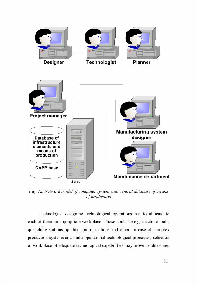
Fig. 12. $etwork model of computer system with central database of means
of production
Technologist designing technological operations has to allocate to
each of them an appropriate workplace. Those could be e.g. machine tools,
quenching stations, quality control stations and other. In case of complex
production systems and multi-operational technological processes, selection
of workplace of adequate technological capabilities may prove troublesome.
Designer
Manufacturing system
designer
Technologist Planner
Server
User User User
User
Project manager
User
Maintenance department
UserCAPP base
Database of infrastructure elements and means of production
51

That problem applies to machine tools in particular. Machine tools have got
different technological capabilities, different ranges of machining
parameters and standard equipment. Designing technological processes in
CAPP systems can be improved through elaboration of models of data
describing technological data and operating features of machine tools. A
computer application should provide quick selection of a workplace
according to assigned criteria. An example here could be linking a
workplace with a technological operation. The application makes available
only those workplaces where a particular operation can be executed (e.g.
selection of grinding operation will make available only grinding machines).
Application for managing workplaces can be also used by people, who
are responsible in an enterprise for traffic maintenance. In the database that
person can store information on dates of planned inspections and the history
of repairs and maintenances of a given machine tool. Hence the system can
signalise with a certain advance, that a given machine tools is going to be
excluded from the traffic because of check-up or repair. The advance should
be defined in such manner, that it would be possible to garner (purchase)
appropriate materials necessary for maintenance or inspection of a machine
tool. The person responsible for technical condition makes an appropriate
entry in the system. In that case the planner has to divert operation onto a
substitutive workplace.
6.1 Designing arrangement of a workplace with presentation in 2D view
In fig. 13 is presented in simplification a developed computer system
module aiding hall design.
52

Fig. 13. Simplified production hall designing–2D view
On the left hand side in fig. 13 are presented workplaces, which can
be situated within the hall. They are: “quality control” and “finished
products storage”. On the right hand side we see 6 workplaces, which have
got already an attributed localisation on the shop floor.
Addition of a workplace to the hall takes place by dragging it from
the bar to the left onto the hall floor or by choosing the option “set”. After
definition of coordinates for workplace’s localisation click the “Set” button
– fig. 14.
53
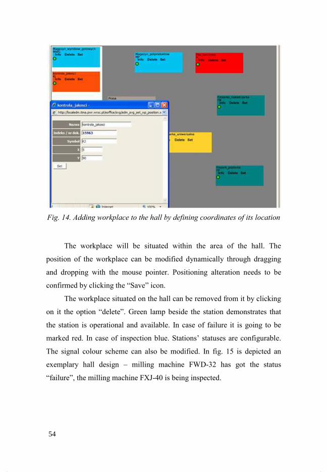
Fig. 14. Adding workplace to the hall by defining coordinates of its location
The workplace will be situated within the area of the hall. The
position of the workplace can be modified dynamically through dragging
and dropping with the mouse pointer. Positioning alteration needs to be
confirmed by clicking the “Save” icon.
The workplace situated on the hall can be removed from it by clicking
on it the option “delete”. Green lamp beside the station demonstrates that
the station is operational and available. In case of failure it is going to be
marked red. In case of inspection blue. Stations’ statuses are configurable.
The signal colour scheme can also be modified. In fig. 15 is depicted an
exemplary hall design – milling machine FWD-32 has got the status
“failure”, the milling machine FXJ-40 is being inspected.
54
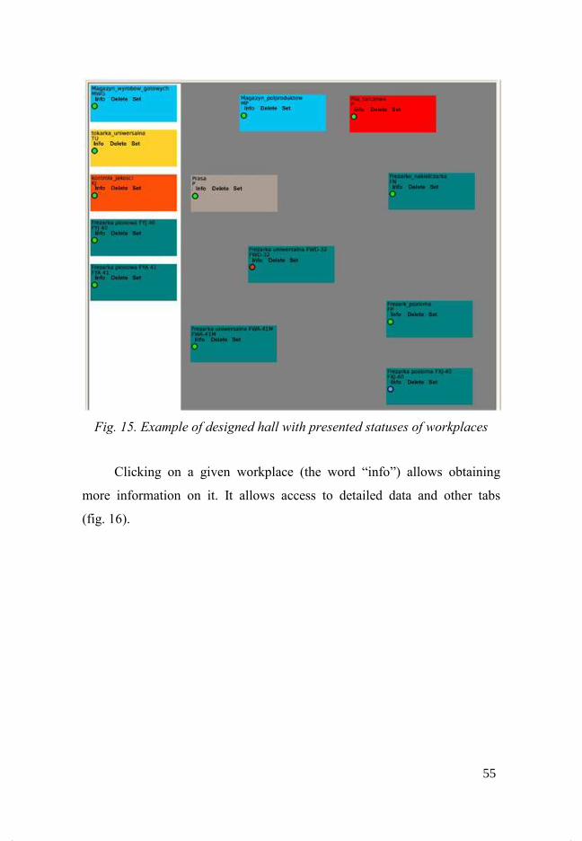
Fig. 15. Example of designed hall with presented statuses of workplaces
Clicking on a given workplace (the word “info”) allows obtaining
more information on it. It allows access to detailed data and other tabs
(fig. 16).
55
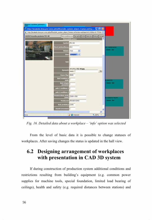
Fig. 16. Detailed data about a workplace – ‘info’ option was selected
From the level of basic data it is possible to change statuses of
workplaces. After saving changes the status is updated in the hall view.
6.2 Designing arrangement of workplaces with presentation in CAD 3D system
If during construction of production system additional conditions and
restrictions resulting from building’s equipment (e.g. common power
supplies for machine tools, special foundation, limited load bearing of
ceilings), health and safety (e.g. required distances between stations) and
56

other must be taken into account the functionality of presented application
for 2D presentation is insufficient. One should use an application, which
will allow for generation of 3D plans and will allow for a broader take on
the problem of designing production systems. Analysis of capabilities of the
Solid Works CAD system proved, that it possesses the functions, which
allow for constructing a hall model. Additionally it has the possibility of
writing own programs in the Visual Basic language using the API.
In order to build a 3D model of a hall, the module for creating
assembly documents in the Solid Works system is used. Inserted
components can change their localisation along three axes. In case of
designing production halls it had been established, that the hall (floor) is
located at the z=0 height. During insertion of 3D models of workplaces into
the assembly, the application Layout-3D automatically adds the relation
“Merged” between the surface representing the area occupied and the main
plane for the entire assembly. Such constraint means, that when moving
stations by means of a mouse, the Z coordinate does not change. Generated
by the system mates are shown in fig. 17.
Fig. 17. Mates generated by the Layout-3D application
57
Information on workplace’s localisation within the production hall is
available under the “Location” option. Those are X and Y coordinates.
Alternation of location’s coordinates and clicking on the “Save” icon causes
displacement of the workplace.
Computer systems ought to be used very cautiously. The solution
suggested by the computer should be considered as preliminary for further
consideration. Computer cannot make decisions for us in terms of
arrangement of objects.
58
7 Computer systems for simulation
of production processes
Available in the market systems for simulation (e.g. ProModel,
iGrafx) rely on a LAYOUT plan constructed by the user and cannot
optimise it. They only analyse what is going on in the production system,
provided that workplaces are immobile. Furthermore dimensions of
workplaces are irrelevant along with their workspaces. Thus it is impossible
to build a model of a real size.
7.1 iGrafx system
The iGrafx system, product of Corel is a consistent system of diverse
graphical tools dedicated for enterprises. Graphics increases the
effectiveness of communication through visualisation of content. iGrafx
system provides tools adequate to needs and possibility of utilising them by
certain users at the enterprise level. Common base resources for all elements
of the system in tandem with common formats of graphical documents
allow for sharing graphics irrespectively of application, in which they were
created (all applications of the iGrafx system cooperate with each other at
the same level of integration as MS Office applications do). At the same
time advanced, often unique functions included in modules dedicated to
specialised users, guarantee satisfaction of their even most sophisticated
needs. Components of the iGrafx system are intended for working in
network and have got built-in mechanism limiting work of administrators
connected with managing them. iGrafx program is intended for aiding
planning and creation of organisation of labour in firms and enterprises. The
program allows for process modelling through:
59
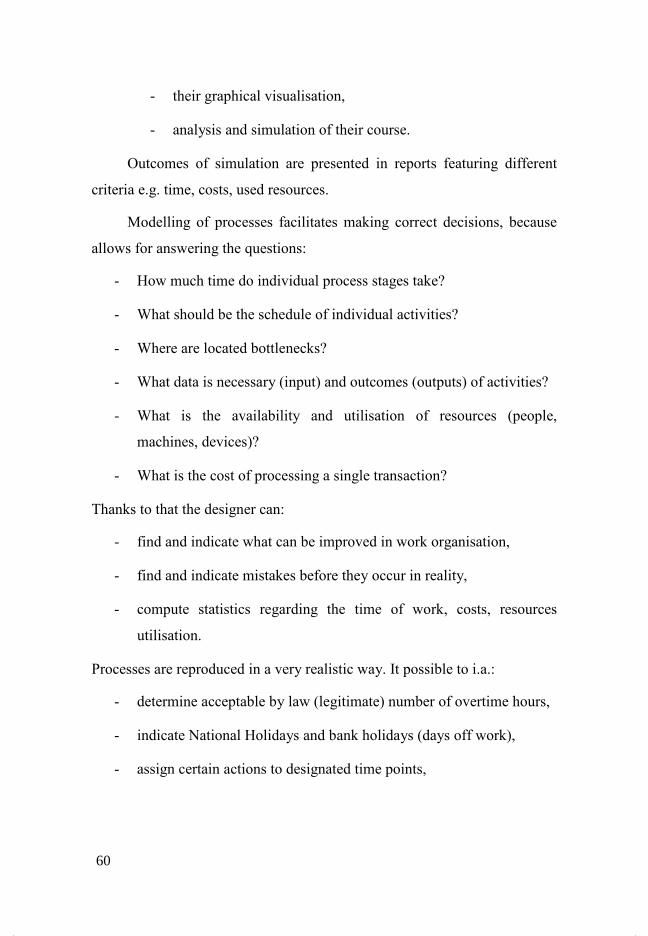
- their graphical visualisation,
- analysis and simulation of their course.
Outcomes of simulation are presented in reports featuring different
criteria e.g. time, costs, used resources.
Modelling of processes facilitates making correct decisions, because
allows for answering the questions:
- How much time do individual process stages take?
- What should be the schedule of individual activities?
- Where are located bottlenecks?
- What data is necessary (input) and outcomes (outputs) of activities?
- What is the availability and utilisation of resources (people,
machines, devices)?
- What is the cost of processing a single transaction?
Thanks to that the designer can:
- find and indicate what can be improved in work organisation,
- find and indicate mistakes before they occur in reality,
- compute statistics regarding the time of work, costs, resources
utilisation.
Processes are reproduced in a very realistic way. It possible to i.a.:
- determine acceptable by law (legitimate) number of overtime hours,
- indicate National Holidays and bank holidays (days off work),
- assign certain actions to designated time points,
60

- introduce probability of failure or indisposition of individual process
participants.
Results of the analysis and simulation of process courses along with a
graphic representation of the scheme, can be saved in form of HTML and
send out to all interested people via the company’s Intranet.
7.2 ProModel
ProModel is a system for simulation and analysis of production
systems of different types and sizes, working in the Windows environment.
ProModel is an easy to use, complete and flexible tool, moreover allows for
realistic simulation. It can be customised according to individual needs by
expanding own graphical libraries containing workplaces, production
resources etc. As a discrete event simulator, ProModel is intended above all
for modelling discrete parts of production systems, although it can model
continuous industrial process, e.g. filling and emptying the tank with fuel.
ProModel allows for simulation of processes with precision of from 0.1
hour to 0.00001 s.
Construction of a model takes place in the following stages:
1 – Construction and definition of a virtual model of workplaces
allocation of examined manufacturing system
In the Locations module (fig. 18) we present standing points of a
manufacturing system, through which pass manufactured elements.
61
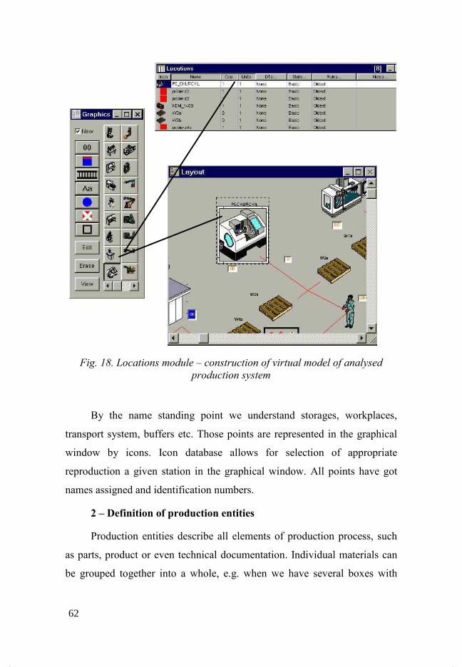
Fig. 18. Locations module – construction of virtual model of analysed
production system
By the name standing point we understand storages, workplaces,
transport system, buffers etc. Those points are represented in the graphical
window by icons. Icon database allows for selection of appropriate
reproduction a given station in the graphical window. All points have got
names assigned and identification numbers.
2 – Definition of production entities
Production entities describe all elements of production process, such
as parts, product or even technical documentation. Individual materials can
be grouped together into a whole, e.g. when we have several boxes with
62
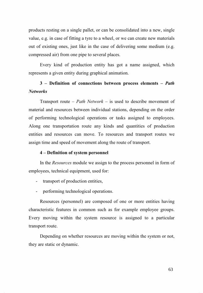
products resting on a single pallet, or can be consolidated into a new, single
value, e.g. in case of fitting a tyre to a wheel, or we can create new materials
out of existing ones, just like in the case of delivering some medium (e.g.
compressed air) from one pipe to several places.
Every kind of production entity has got a name assigned, which
represents a given entity during graphical animation.
3 – Definition of connections between process elements – Path
�etworks
Transport route – Path $etwork – is used to describe movement of
material and resources between individual stations, depending on the order
of performing technological operations or tasks assigned to employees.
Along one transportation route any kinds and quantities of production
entities and resources can move. To resources and transport routes we
assign time and speed of movement along the route of transport.
4 – Definition of system personnel
In the Resources module we assign to the process personnel in form of
employees, technical equipment, used for:
- transport of production entities,
- performing technological operations.
Resources (personnel) are composed of one or more entities having
characteristic features in common such as for example employee groups.
Every moving within the system resource is assigned to a particular
transport route.
Depending on whether resources are moving within the system or not,
they are static or dynamic.
63

5 – Definition of production process.
In the Processes module we describe behaviour of the process in time.
We define flow of materials through the system and where technological
operations upon a given material are performed. Material can be transported
to the next place, only when the capacity for a given location is reached.
6 – Definition of process feed.
For description of manufacturing system feed is responsible the
Arrivals module. Delivery is defined as any kind and size of batch of
material entered into the production system. Deliveries can be set in
accordance with production plan, in periodic intervals, in ascending or
descending quantity according to a strictly determined pattern, or as a result
of any event taking place in the model. If acceptable by the system capacity
delivery is exceeded, it is plainly rejected from it.
In ProModel suite, application performing optimisation process is
SimRunner.
The first step for analysing the model subject to simulation is the
analysis, which factors influence the system behaviour and what is the
extent of that influence.
SimRunner (fig. 19) allows for measuring effects of changes, at
altered influence extents of a particular system factor. By conducting a
series of experiments, it is possible to calculate effects of value alteration of
particular factors and selection of optimum value of the objective function.
64
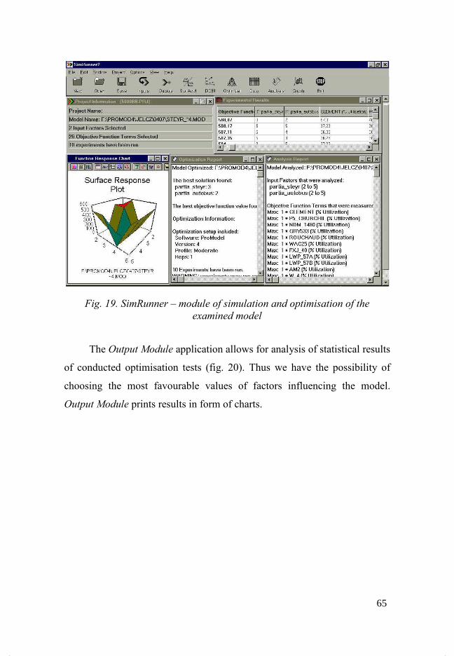
Fig. 19. SimRunner – module of simulation and optimisation of the
examined model
The Output Module application allows for analysis of statistical results
of conducted optimisation tests (fig. 20). Thus we have the possibility of
choosing the most favourable values of factors influencing the model.
Output Module prints results in form of charts.
65

Fig. 20. Output Module – analysis of statistical results of conducted
simulation
The final report includes extensive statistics regarding workplaces,
production resources, items manufactured in the modelled system. Separate
detailed statistics are owned by workplaces, production resources and
products, e.g. for products and raw materials is computed the percentage of
displacement time, lead time for production resources, in operation and
blocked.
66
8 Methods of optimisation of
workplace allocation
Two groups of methods can be distinguished:
- for cellular structure,
- for structure without division into workcells.
Below are presented several methods, which allow for obtainment of
workplace allocation propositions. The Rank Order Clustering method
applies to cellular structure. The CRAFT method can be used for systems
without separated cells. There are many more optimisation methods. Their
description is available in literature.
8.1 Rank Order Clustering Method
This method assigns a binary value to every row and column,
transposes rows and columns in descending order of their binary values, on
that basis equipment of future workcell and produced there parts is
determined. The method is very simple and easy in application. In the ROC
method six basic steps have to be taken [3]:
Step 1 – Assignment of binary value
WBj = 2m – j,
where: m – number of machine tools in every column j
in the part-machine tool matrix.
Step 2 – Determination of decimal equivalent DE for every
binary value in the row i following the formula:
67
ij
jmm
ji aED −
=Σ= 21
where: aij – matrix of machine tool-part relationships
Step 3 – Setting of rows in the order of descending values of the
decimal equivalent DE. If further row transposition is not
needed, the algorithm execution has to be stopped, otherwise
proceed to the step 4.
Step 4 – Every row in the matrix needs to have a binary value
assigned
WBj = 2 n– i ,
where: n – number of parts
Step 5 – Determination the decimal equivalent DE for every
binary value in the j column following the formula:
ij
inn
ij aED −
=Σ= 21
Step 6 – Setting of columns in the order of descending value of
their decimal equivalent. Order columns following the DE
values for each column. If there is a need of further column
transposition, proceed to the step 1.
The downside of this algorithm is the fact that the final solution
depends on the initial arrangement of rows and columns in the matrix.
68
8.2 CORELAP method (Computerized Relationship Layout Planning)
This algorithm differs substantially from previously presented
allocation methods. The majority of methods assumes as optimisation
criterion only one type of relationships between elements of production
system, usually those being transport relationships. Transport relationships
are not the only relationships between workplaces. Many issues take into
account also other functional relationships of workplaces, amongst which
we can include [4], [28], [23]:
- provision of appropriate personnel,
- effective supervision,
- enabling contact between employees,
- flow of documentation,
- technological relationships (e.g. using the same work stations),
- noise and others,
To appraise the total closeness rating a six-degree alpha-numeric scale was
used (table 3):
69

Table 3. Six-degree alpha-numeric scale of total closeness rating [28]
Character
scale Total closeness rating
Numerical
scale
A Absolutely necessary 6
E Very important 5
I Important 4
O Ordinary 3
U Unimportant 2
X Undesirable 1
CORELAP technique allows for inclusion of many kinds of
relationships between objects. Selection of relationships, which are included
is discretionary and depends on designer. CORELAP method [3], [4], [28],
[23], [26] is approximate, stepwise and modular with unlimited possibility
of choosing the place.
The starting point in the CORELAP method is the matrix of functional
relationships of arranged objects. The idea dictates such allocation of
objects, that degrees of required closeness recorded in the SF matrix are
satisfied, what means, that for example objects i, j of relationship strength A
need to unconditionally stand next to each other, whilst objects i, j of X
strength cannot be in any case neighbours.
For this method the following sum must be minimised:
∑∑−
= +=
=1
1 1
*$
i
$
ij
ij
F
ij LSQ
where:
70
SFij – degree of demanded i, j objects closeness according to six-
degree scale
Lij – distance between places of i and j objects allocation, where
Cartesian distance measure was adopted
22 )()( jijiij YYXXL −+−=
In the CORELAP method calculations are made in two stages:
determination of succession of arranged objects and selection of places of
their localisation. Realisation of individual stages may take place serially or
be parallelised. Objects are arranged in nodes of orthogonal net, which is
usually presented in form of the U matrix. Its elements represent numbers of
arranged objects. Set of identical elements, which are of equal values,
creates the outline of object arrangement shape. Every element of the U
matrix corresponds to a modular surface unit. Shape of the surface, where
objects will be allocated can be imposed by entering for example the a
parameter being the ratio of sides of the U matrix. Before commencing the
relevant calculations the following activities are performed:
- Surface estimation (dimensions of the orthogonal net – U matrix) in
modular units for allocation of all objects.
- Calculation for all objects sums of total closeness rating TCRi
according to the formula:
,1∑=
=$
j
F
iji STCR
, i = 1, 2, ... , N
- Creation of object list in the order of descending sums of closeness
rating.
In the CORELAP method at every step only one object is arranged.
All objects arranged according to non-growing sums of closeness rating are
71

C type objects, that is candidates for allocation. As first are arranged objects
with the highest values of TCR. It is located in the centre of the net.
Simultaneously it becomes a type W object. It is sequentially checked if
there are amongst remaining objects – candidates for allocation – such ones,
which would have type A relationships with W object. If yes, it becomes
type V object and it is positioned possibly close to W object on the
allocation plan. If there are several type V objects, we choose for
arrangement one, which has the highest sum of total closeness rating TCR.
If there are several such objects also, we pick one of our choosing. Next
type V objects are being searched for. If there still are object having type A
relationships with type W objects, the entire process is repeated. If there are
no objects of such relationship, it is explored, whether type V objects have
got type A relationships with the C objects, not allocated yet. If yes, such an
object becomes type W object and it is situated on the allocation plan, whilst
the C object, with which A had relationship, becomes candidate for
allocation, so the V object. If neither of W and V objects do not have type A
relationships with the C objects, the closeness rating is lowered by 1 to I, O,
and the entire process repeats. Found object becomes of the W type and is
situated on the allocation plan. Now type V object of A relationships is
searched for it amongst type C objects and so forth.
As a result of the process several loose groups of objects are created,
which are focused around objects of high total closeness rating sums.
72
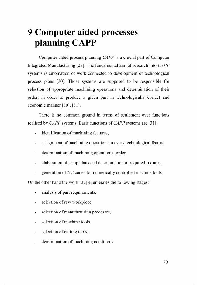
9 Computer aided processes
planning CAPP
Computer aided process planning CAPP is a crucial part of Computer
Integrated Manufacturing [29]. The fundamental aim of research into CAPP
systems is automation of work connected to development of technological
process plans [30]. Those systems are supposed to be responsible for
selection of appropriate machining operations and determination of their
order, in order to produce a given part in technologically correct and
economic manner [30], [31].
There is no common ground in terms of settlement over functions
realised by CAPP systems. Basic functions of CAPP systems are [31]:
- identification of machining features,
- assignment of machining operations to every technological feature,
- determination of machining operations’ order,
- elaboration of setup plans and determination of required fixtures,
- generation of NC codes for numerically controlled machine tools.
On the other hand the work [32] enumerates the following stages:
- analysis of part requirements,
- selection of raw workpiece,
- selection of manufacturing processes,
- selection of machine tools,
- selection of cutting tools,
- determination of machining conditions.
73

In the work [33] is given the following scope of tasks realised by CAPP
systems:
- analysis of design documentation,
- determination of machining operations,
- selection of tools for execution of individual operations,
- elaboration of fixtures,
- determination of requirements of individual setups,
- selection of cutting tools,
- determination of machining operations’ order,
- selection of machining parameters,
- development of $C programs,
- simulation of developed $C programs.
In the majority of cases, selection of machining technology is limited
to machining. It follows from the fact, that this type of material removal
process is still the most wide-spread and commonly used in the industry
[34]. By analysing publications dedicated to CAPP systems one can
observe, that utilisation of features for integration of generative systems
with CAD systems is the dominant approach. According to some scientists,
all currently developed generative CAPP systems use features [35].
Further stages of a CAPP system’s operating, after features
identification, include:
- determination of the type and order of machining operations,
- selection of machine tools, tools and fixtures,
- determination of machining parameters.
74

With the stage of determining demanded machining operations, is also
related determination of their order. Two tasks constitute that stage. Firstly,
technologically correct machining operations’ order needs to be established,
which is sometimes called the critical order of machining operations. Failing
to keep that order can render impossible to achieve specified in
documentation dimension and shape precision, or even prevent
technological process from realisation. An example can be the necessity of
machining datum surfaces prior to machining a part’s elements, which use
those surfaces, or machining of features nested in other features. The second
optional stage is optimisation of operation order by maintaining beforehand
established, critical sequence of operations. Those issues are going to be
described in detail in further part of the work.
The effect of a generative CAPP system’s operation should be
documentation, including all necessary parameters of machining operations.
The work on CAPP systems shows, that perhaps in the future, those systems
will be capable of generating control programs for NC machine tools.
The very first CAPP system was created in 1976 [30]. Since then
many work and research has gone into development of ever-finer solutions
or focusing on chosen problems related to construction of those systems.
Amongst computer methods improving the work of technologist three
major approaches are distinguished: variant, semi-generative and generative
process planning – fig. 21.
75
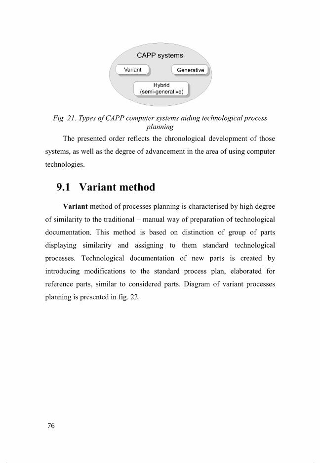
Fig. 21. Types of CAPP computer systems aiding technological process
planning
The presented order reflects the chronological development of those
systems, as well as the degree of advancement in the area of using computer
technologies.
9.1 Variant method
Variant method of processes planning is characterised by high degree
of similarity to the traditional – manual way of preparation of technological
documentation. This method is based on distinction of group of parts
displaying similarity and assigning to them standard technological
processes. Technological documentation of new parts is created by
introducing modifications to the standard process plan, elaborated for
reference parts, similar to considered parts. Diagram of variant processes
planning is presented in fig. 22.
Generative
Hybrid(semi-generative)
CAPP systems
76
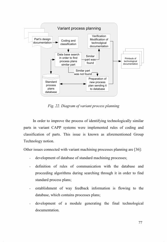
Fig. 22. Diagram of variant process planning
In order to improve the process of identifying technologically similar
parts in variant CAPP systems were implemented rules of coding and
classification of parts. This issue is known as aforementioned Group
Technology notion.
Other issues connected with variant machining processes planning are [36]:
- development of database of standard machining processes;
- definition of rules of communication with the database and
proceeding algorithms during searching through it in order to find
standard process plans;
- establishment of way feedback information is flowing to the
database, which contains processes plans;
- development of a module generating the final technological
documentation.
Part’s design
documentation Coding and
classification
Variant process planning
Data base search
in order to find
process plans
similar part
Standard
process
plans
database
Verification
Modification of
technolgical
documentation
Similar
part was
found
Preparation of
new process
plan sending it
to database
Similar part
was not found
Printouts of
technological
documentation
77

An interesting approach to coding and grouping of machine parts is
presented in the work [37]. The author had developed a method of digital
representation of machine elements and a method of grouping parts in terms
of design and technology utilising the neuron network. Two-layer network
architecture of Kohonen type was built allowing for grouping parts of
machines. Coding of machine elements had been performed on basis of
characteristics of design and technological features, influencing selection of
technologies. The digital representation of a part was obtained by
development of a feature vector, including figure data characterising
individual features of a given part [37].
The variant method of planning technological processes had been used
in the SYSKLASS [38] integrated system. In that system identification of
essential parameters of produced parts is realised through use of a classifier,
based on hierarchical combination of part’s shape and parameters
identification methods. Helpful in that operation are design features bases
and element’s properties, and data connected to the manufacturing process.
Variant manner of system operation manifests itself at the stage of
developing manufacturing technologies, through the possibility of using
technological information included in the known solutions base and
previous results of technical production preparation [38].
Next example of a variant CAPP system, is computer system aiding
process planning for shafts - POLCAP [39], [40]. That system, developed
in Institute of Engineering Technology of Poznan University of Technology,
characterises with modular structure. Elaboration of technology takes place
in form of dialog with the computer. By means of it, were developed the
structure of technological process and individual technological operations.
Designing of process takes place on the basis of a typical technological
process, with its possible variants, for a chosen item class – shafts.
78

Variant method of process planning in CAPP systems is characterised
by many advantages. First and foremost it imposes systemisation of an
enterprise’s products through coding and classifying [41]. Introduction of
databases to a great extent eliminates from a technologist’s work activities
not directly linked to taking technological decisions. It shortens the time of
elaborating technological documentation through usage of standard plans,
technological processes executed beforehand. Due to utilisation of that
technological documentation, the probability of failure occurrence in the
production phase falls on account of fact, that defined processes were
already previously verified.
Presented method characterises however, with serious flaws. The most
important one is the necessity of manual elaboration of technological
documentation in case, when there is a need for developing manufacturing
technology for a part, whose technological documentation was not placed
before in the database of standard machining processes. Similarly in the
case, when in enterprise’s production system appears a new machine tool or
possibility of performing new technological processes, the current
technological process plans need to be manually verified and changes
imposed by new manufacturing possibilities implemented. Above-
mentioned inconveniences imply next serious drawback of the variant
method in process planning - the necessity of employing a highly skilled
technologist at the post of technological process planner. His knowledge and
experience are key indicators of correct functioning of a variant CAPP
system. In that case it may be noted, that computer technologies employed
at variant process planning are only tools aiding the technologist’s work,
and the most important matters during elaboration of manufacturing
technology he still examines himself [36].
79
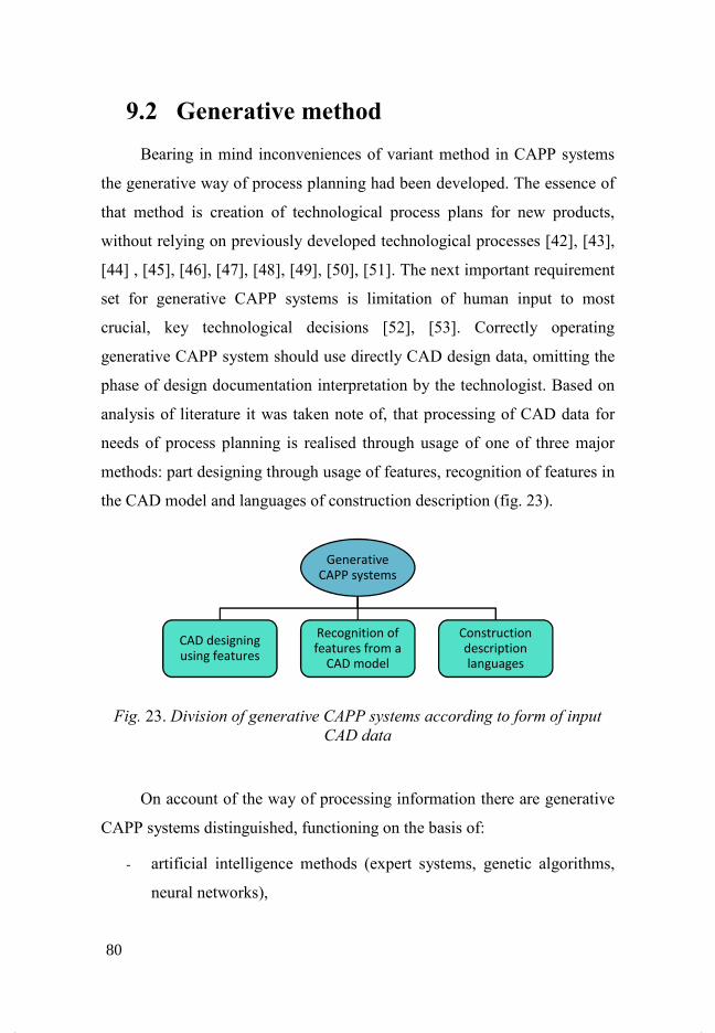
9.2 Generative method
Bearing in mind inconveniences of variant method in CAPP systems
the generative way of process planning had been developed. The essence of
that method is creation of technological process plans for new products,
without relying on previously developed technological processes [42], [43],
[44] , [45], [46], [47], [48], [49], [50], [51]. The next important requirement
set for generative CAPP systems is limitation of human input to most
crucial, key technological decisions [52], [53]. Correctly operating
generative CAPP system should use directly CAD design data, omitting the
phase of design documentation interpretation by the technologist. Based on
analysis of literature it was taken note of, that processing of CAD data for
needs of process planning is realised through usage of one of three major
methods: part designing through usage of features, recognition of features in
the CAD model and languages of construction description (fig. 23).
Fig. 23. Division of generative CAPP systems according to form of input
CAD data
On account of the way of processing information there are generative
CAPP systems distinguished, functioning on the basis of:
- artificial intelligence methods (expert systems, genetic algorithms,
neural networks),
Generative
CAPP systems
CAD designing
using features
Recognition of
features from a
CAD model
Construction
description
languages
80

- databases with extensive DBMS management system (Data Base
Management Systems) [54].
9.2.1 Features in generative process planning
Features are defined in many different ways, depending on in which
area the term is used. The general definition of the term “feature” is:
“Feature represents, from engineering point of view, a set of
parameters characterising properties of parts or assembly” [55].
Similar definition was formulated in the work [56]:
“Feature is a set of information about an item, including
geometrical and technological characteristics, of different
level of complexity and hierarchy, used during construction,
designing of technological processes or other engineering
work”
In the area of product design, features as geometric primitives, are
used for ensuring functional demands of designed part [44]. Example: a rib
is a design feature applied for increasing a part’s rigidity. An example of a
part with highlighted design features is presented in fig. 24 [57].
81
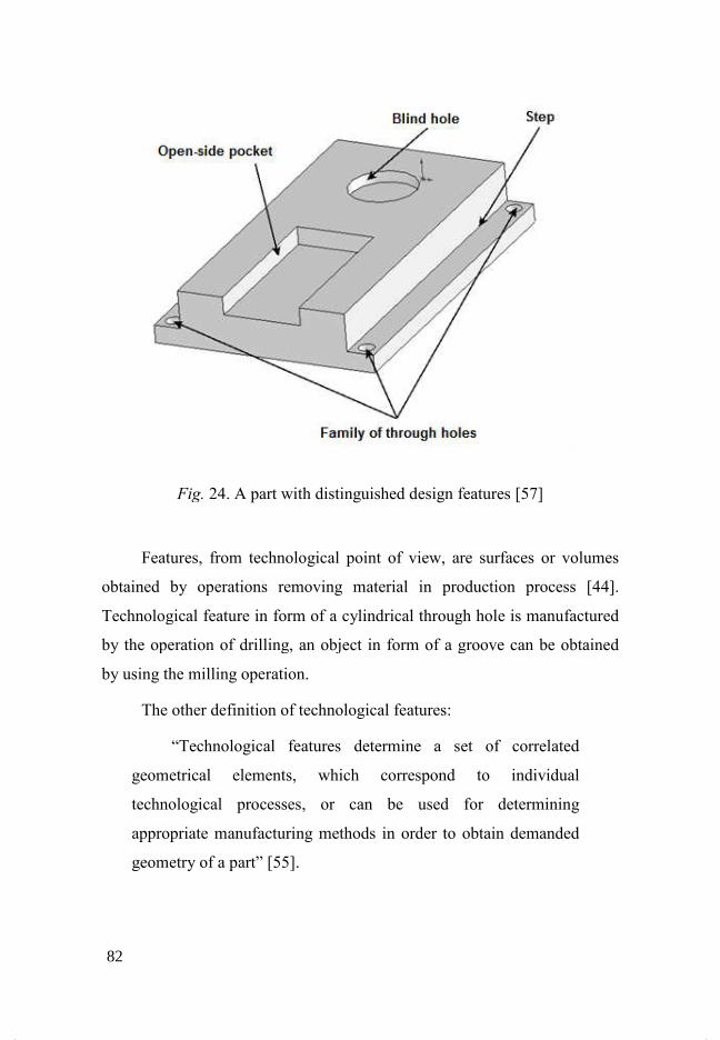
Fig.
Features, from technological point of view, are surfaces or volumes
obtained by operations removing material in production process
Technological feature in form of a cylindrical through hole is manufactured
by the operati
by using the milling operation.
The other definition of technological features:
“Technological features determine a set of correlated
geometrical elements, which correspond to individual
technological processes, or can be used for determining
appropriate manufacturing methods in order to obtain demanded
geometry of a part”
Fig. 24. A part with distinguished design features
Features, from technological point of view, are surfaces or volumes
obtained by operations removing material in production process
Technological feature in form of a cylindrical through hole is manufactured
by the operation of drilling, an object in form of a groove can be obtained
by using the milling operation.
The other definition of technological features:
“Technological features determine a set of correlated
geometrical elements, which correspond to individual
logical processes, or can be used for determining
appropriate manufacturing methods in order to obtain demanded
geometry of a part” [55].
features [57]
Features, from technological point of view, are surfaces or volumes
obtained by operations removing material in production process [44].
Technological feature in form of a cylindrical through hole is manufactured
on of drilling, an object in form of a groove can be obtained
“Technological features determine a set of correlated
geometrical elements, which correspond to individual
logical processes, or can be used for determining
appropriate manufacturing methods in order to obtain demanded
82

The STEP norm (STandard for Exchange of Product data) AP-224 of
series ISO 10303 “Definition of mechanical products for planning processes
by means of machining features” includes division of technological features
into four types: machining, temporary, replicated and complex features
(fig. 25).
Fig. 25. Technological division of features according to STEP AP-224
An example of parts with distinguished technological features is
presented in fig. 26.
general
family
circular
family
rectangular
family
Technological Features
Machining
features
Transition
features
Replicated
features
Complex
features
boss
slot
step
thread
...
fillet
chamfer
edge round
83

Fig. 26. Example of a part and extracted from it features [55]
9.2.2 Forward and backward process planning
The task of generative CAPP systems is to define a plan of
technological processes determining the way of transforming the raw
material into a finished product. There are two methods known of
procedures for dealing with process designing:
- forward planning,
- backward planning [58], [36].
The square one in forward planning of processes is the initial state of
the part processed in form of raw workpiece. Through determination of
machining operations are removed consecutive technological features, in
form of material volume, until obtainment of final form of processed
part [36].
Backward method of planning processes is the reversal of the code of
practice in relation to forward planning. The initial state of the item is its
final form, enclosed in the design documentation. Next, intermediate state of
the item is obtained through taking into account requirements of surface
84
finishing precision and addition of operational machining allowance, which
will be removed in successive machining operations. As an effect of those
proceedings a rough shape of the raw workpiece is obtained. The final form
of the raw workpiece is established by taking into account other factors than
just the geometry of processed item e.g. volume of the production batch, or
material properties of a given part.
Customarily the design documentation describes the product designed
in the final form, exclusive of raw worpiece, this being the case, the forward
method of planning processes has not found a wider application in practice.
The difficulty of forward planning follows from the fact, that it is
troublesome to determine the raw worpiece, which constitutes the starting
form of item in the process planning method described.
In practice backward planning of technological processes is
commonly used. Usage of that method for generation of intermediate states
of processed items is presented in the work [58].
9.2.3 Obtainment of technological features
In backward planning, widespread are technological features (TF).
They determine the most important information about the geometry of
machined item, processed from design documentation for the need of
preparing manufacturing technologies. Geometrical CAD design data during
transformation into TF are enriched in additional information required by
technologists, being e.g. detailed material data, special requirements about
the surface quality after machining. During integration of CAD design
environment with the area of planning manufacturing process CAPP, the
process of obtaining TF from design data can be divided into two
mainstreams [44], [59], [60], [61], [62], [63]:
- design by features,
85
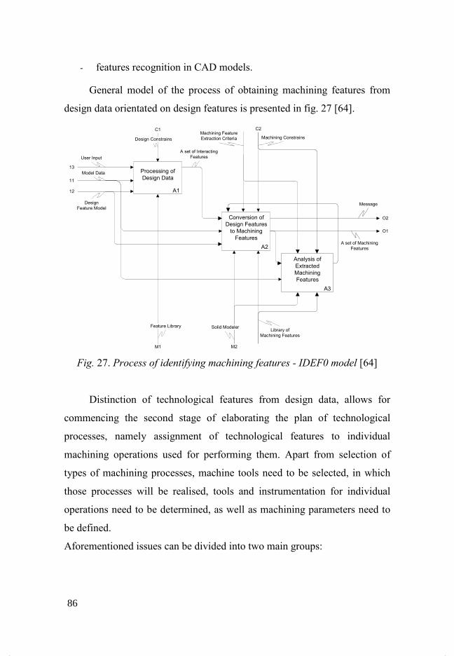
- features recognition in CAD models.
General model of the process of obtaining machining features from
design data orientated on design features is presented in fig. 27 [64].
Fig. 27. Process of identifying machining features - IDEF0 model [64]
Distinction of technological features from design data, allows for
commencing the second stage of elaborating the plan of technological
processes, namely assignment of technological features to individual
machining operations used for performing them. Apart from selection of
types of machining processes, machine tools need to be selected, in which
those processes will be realised, tools and instrumentation for individual
operations need to be determined, as well as machining parameters need to
be defined.
Aforementioned issues can be divided into two main groups:
A1
Processing of
Design Data
A2
Conversion of
Design Features
to Machining
Features
A3
Analysis of
Extracted
Machining
Features
Design Constrains
C1
A set of Interacting
FeaturesUser Input
13
11
Model Data
Design
Feature Model
12
Feature Library
M1
Machining Feature
Extraction Criteria
C2
Machining Constrains
O2
Message
O1
A set of Machining
Features
M2
Solid ModelerLibrary of
Machining Features
86
- activities being easy to build algorithms realising them e.g.: selection
of machining parameters, value of operational allowance;
- activities requiring technological knowledge e.g.: selection of
machining type, determination of operations order.
In generative CAPP systems the first group of activities does not pose
any major hardships during computer implementation. Using norms,
alignment charts and other numeric data for processes planning allows for
building algorithms for programs selecting numerical data of machining
parameters based on information entered from aforementioned sources.
The second group of above-mentioned issues, requires application of
decision logic, when solving certain problems. The most commonly used, in
that area, methods of supporting the decisional process are: decision trees,
expert systems, neural and semantic networks, genetic algorithms.
9.2.4 Expert systems in generative CAPP systems
The most widespread method aiding planning of technological
decision processes are expert systems. Those systems constitute a part of
branch of knowledge called artificial intelligence. The task of those systems
- which are also called advisory systems – is proposing to the user certain
variants of solutions for specified earlier problems, requiring undertaking a
decision. The user may accept or reject the solution suggested. Correct
functioning of expert system is possible only, when appropriate amount of
knowledge from a given field – in the case being described – technological
knowledge has been entered into the knowledge base. Unquestionable
advantage of expert systems is the possibility of aggregating in them
capacious technological knowledge in a systemised manner in form of:
facts, production rules [65]. Such form of knowledge representation allows
for accumulation of messages and data from different specialists from a
87

manufacturing domain, enriching the functionality and capabilities of the
expert system in terms of aiding decision process during preparation of
technological documentation.
Usage of an expert system in the area of technical production
preparation is presented in fig. 28 [66].
Fig. 28. Application of expert system in technical production
preparation [66]
In presented way of using an expert system in the area of
manufacturing technology preparation, production process designing is
aided by means of entered data on the decision problem and analysis of
technological capabilities of a particular manufacturing system. Solution of
a concrete technological task depends on technological knowledge,
implemented in the expert system, presented in form of detailed
technological rules obtained from experts – technologists. User of the
system enters input data, providing information necessary for module
processing technological knowledge, what allows for generation of certain
set of solutions of a particular task. Accepted solutions are stored in
KNOWLEDGE BASE
1. General and detailed rules of
building technological processes
2. Knowledge following from
experience
3. Product’s technological
processes structure
EXPERT
USER
Input data:
- constructional & technological
product characteristics
- production program and other
MANUFACTURING
SYSTEM DATA
1. Data about technological
capabilities of a particular
manufacturing system
2. Technological normativesPRODUCTION
SYSTEM
GENERATIVE
MODULE
Generating technological
documentation
INPUT DATA
ENTERING MODULE
88
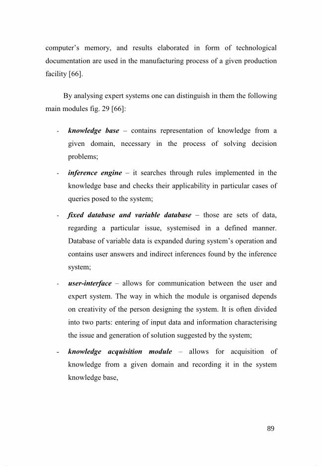
computer’s memory, and results elaborated in form of technological
documentation are used in the manufacturing process of a given production
facility [66].
By analysing expert systems one can distinguish in them the following
main modules fig. 29 [66]:
- knowledge base – contains representation of knowledge from a
given domain, necessary in the process of solving decision
problems;
- inference engine – it searches through rules implemented in the
knowledge base and checks their applicability in particular cases of
queries posed to the system;
- fixed database and variable database – those are sets of data,
regarding a particular issue, systemised in a defined manner.
Database of variable data is expanded during system’s operation and
contains user answers and indirect inferences found by the inference
system;
- user-interface – allows for communication between the user and
expert system. The way in which the module is organised depends
on creativity of the person designing the system. It is often divided
into two parts: entering of input data and information characterising
the issue and generation of solution suggested by the system;
- knowledge acquisition module – allows for acquisition of
knowledge from a given domain and recording it in the system
knowledge base,
89
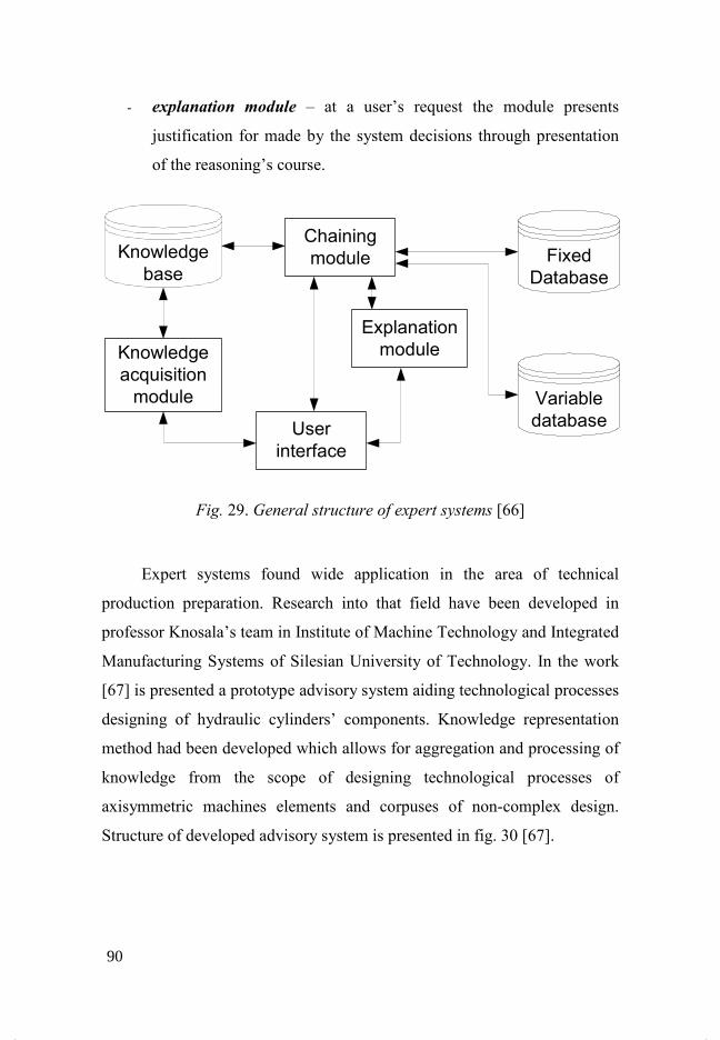
- explanation module – at a user’s request the module presents
justification for made by the system decisions through presentation
of the reasoning’s course.
Fig. 29. General structure of expert systems [66]
Expert systems found wide application in the area of technical
production preparation. Research into that field have been developed in
professor Knosala’s team in Institute of Machine Technology and Integrated
Manufacturing Systems of Silesian University of Technology. In the work
[67] is presented a prototype advisory system aiding technological processes
designing of hydraulic cylinders’ components. Knowledge representation
method had been developed which allows for aggregation and processing of
knowledge from the scope of designing technological processes of
axisymmetric machines elements and corpuses of non-complex design.
Structure of developed advisory system is presented in fig. 30 [67].
Knowledge
baseFixed
Database
Variable
database
Chaining
module
Explanation
module
User
interface
Knowledge
acquisition
module
90
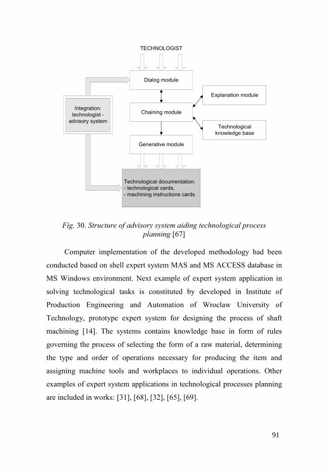
Fig. 30. Structure of advisory system aiding technological process
planning [67]
Computer implementation of the developed methodology had been
conducted based on shell expert system MAS and MS ACCESS database in
MS Windows environment. Next example of expert system application in
solving technological tasks is constituted by developed in Institute of
Production Engineering and Automation of Wroclaw University of
Technology, prototype expert system for designing the process of shaft
machining [14]. The systems contains knowledge base in form of rules
governing the process of selecting the form of a raw material, determining
the type and order of operations necessary for producing the item and
assigning machine tools and workplaces to individual operations. Other
examples of expert system applications in technological processes planning
are included in works: [31], [68], [32], [65], [69].
Technological documentation:
- technological cards,
- machining instructions cards
Dialog module
TECHNOLOGIST
Chaining module
Generative module
Explanation module
Technological
knowledge base
Integration:
technologist -
advisory system
91

10 Features in technical production preparation
Fundamental definitions regarding features in the area of elaborating
manufacturing processes were presented in the previous chapter. As
aforementioned there are two fundamental types of features distinguished:
design and technological. In hereof paper four types of features are
distinguished: functional features, design, technological and machining
features (fig. 31).
Fig. 31. Features in production preparation
The division is contingent on data character, included in individual types of
objects. It takes into account parts’ functional assumptions, geometry,
Design features
Functional features
Geometrical features
Technological features
Assembly features
Machining features
Precision features Dimensions
Dimension tolerances
Geometrical tolerances
Shape tolerances
Positioning tolerances
Material features
Tensile strength
Main dimensions
Design
Ergonomics
Modularity
Added volume
Removed volume
Solid
Rib
Screw hole
T-groove
Kinematics constrains
Dimensional constrains
Step
Groove
Hole
Volume to be removed in one machining operation
. . .
. . .
. . .
. . .
92
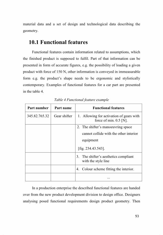
material data and a set of design and technological data describing the
geometry.
10.1 Functional features
Functional features contain information related to assumptions, which
the finished product is supposed to fulfil. Part of that information can be
presented in form of accurate figures, e.g. the possibility of loading a given
product with force of 150 N, other information is conveyed in immeasurable
form e.g. the product’s shape needs to be ergonomic and stylistically
contemporary. Examples of functional features for a car part are presented
in the table 4.
Table 4 Functional feature example
Part number Part name Functional features
345.82.765.32 Gear shifter 1. Allowing for activation of gears with force of min. 0.5 [N].
2. The shifter’s manoeuvring space
cannot collide with the other interior
equipment
[fig. 234.43.543].
3. The shifter’s aesthetics compliant with the style line
4. Colour scheme fitting the interior.
...
In a production enterprise the described functional features are handed
over from the new product development division to design office. Designers
analysing posed functional requirements design product geometry. Then
93

strength analysis are made along with other, which are necessary for a given
part being designed. After completion of those analyses the form of part’s
geometry is elaborated and the material approved, out of which the part is
going to be produced. Already on that stage we can talk about parametric
model of an item, which is represented by means of design objects.
10.2 Design features
Design designing of a new product is executed based on guidelines
included in specification of functional features. In hereof paper there are
four major groups of design features distinguished (fig. 30):
- geometric,
- assembly,
- precision,
- material,
The presented division is contingent on modern CAD systems’
abilities. Geometry of part designed in such a system is modelled by using
mentioned design features. For a complete description of design it is
necessary, not only to build a part’s geometry, but also to give exact
parameters characterising that geometry, so: dimensions, tolerances,
information on surface finish quality, deviation of position and shape,
datums, material parameters, and in case of assemblies of parts – kinetic
constraints between components. The process of modelling a part’s
geometry completed with features is depicted in fig. 32.
94
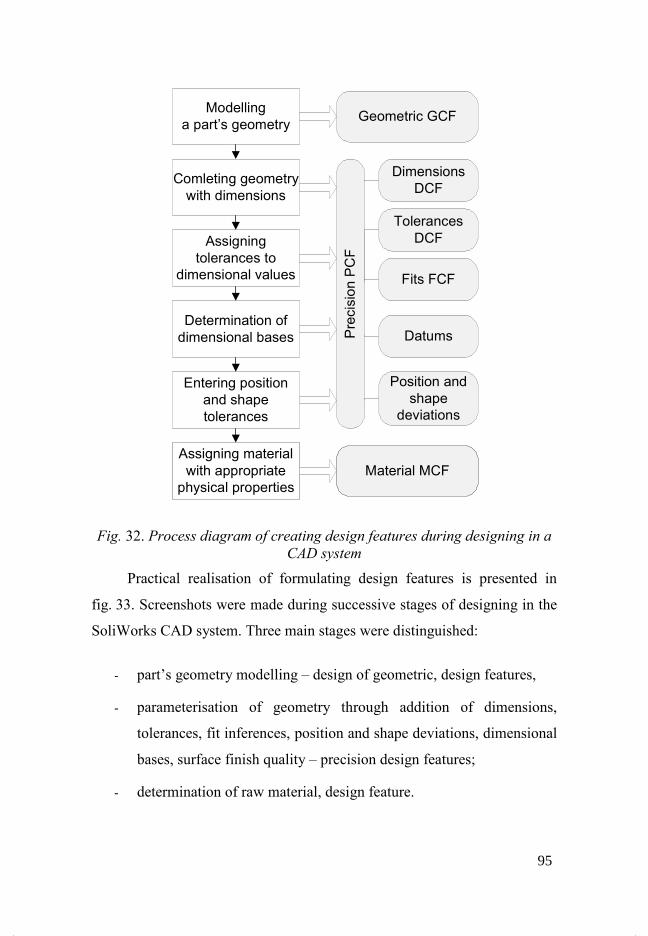
Fig. 32. Process diagram of creating design features during designing in a
CAD system
Practical realisation of formulating design features is presented in
fig. 33. Screenshots were made during successive stages of designing in the
SoliWorks CAD system. Three main stages were distinguished:
- part’s geometry modelling – design of geometric, design features,
- parameterisation of geometry through addition of dimensions,
tolerances, fit inferences, position and shape deviations, dimensional
bases, surface finish quality – precision design features;
- determination of raw material, design feature.
Modelling
a part’s geometry
Comleting geometry
with dimensions
Assigning
tolerances to
dimensional values
Determination of
dimensional bases
Entering position
and shape
tolerances
Assigning material
with appropriate
physical properties
Geometric GCF
Material MCF
Position and
shape
deviations
Precision PCF
Dimensions
DCF
Tolerances
DCF
Fits FCF
Datums
95

Fig. 33. Stages of creating design features: a) design of geometric features
b) addition of precision features c) assigning material to geometry
In practice determination of material and final geometry of designed part
takes place after having made necessary calculations (strength, stresses,
displacements – calculated using FEM analysis , thermal, etc.).
The example presents features characteristic for single parts, it does
not take into account assembly features, which are created in the processes
of joining together components into an assembly.
Modern CAD systems operate on basis of parametric features.
Similarly the designing philosophy in SolidWorks CAD system allows for
designing through addition of successive geometry elements, entering
dimensional values, tolerances, fit inferences etc. determining those
geometric objects. Symptomatic of that system is storing information which
has the structure of data related to computer model of designed part. Figure
34 presents main objects, out of which a part is constructed in the
SolidWorks system. Distinguished here is the structure of dependencies
a)
b) c)
96
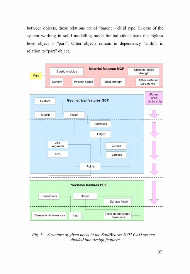
between objects, those relations are of “parent – child type. In case of the
system working in solid modelling mode for individual parts the highest
level object is “part”. Other objects remain in dependency “child”, in
relation to “part” object.
Fig. 34. Structure of given parts in the SolidWorks 2004 CAD system –
divided into design features
Part
Geometrical features GCF
Faces
Edges
Curves
Vertices
Feature
Sketch
Line
segments
Arcs
Points
Surfaces
Precision features PCF
Dimensions
Dimensional tolerances
Datum
Surface finish
Position and shapedeviations
Material features MCFElastic modulus
Poisson’s ratio
Ultimate tensile
strength
Yield strenghtDensityOther material
parameters
„Parent
- child”
relationship
Fits
97
Design process does not require entering all parameters of geometric
features. Supplementation with precision and material parameters of
geometric objects may take place in the subsequent designing stage. The
data structure is updated on a current basis during modelling of individual
stages of geometry along with precision features. Presented way of
recording design features allows for flexible access to that information via
Application Programming Interface – API.
10.3 Technological features The result of designing in a CAD 3D system is computer geometry
model of a part containing information both on geometry as well as
parameters describing it. Direct utilisation in a CAPP system of design data
in that form is impossible. Necessary becomes distinction of technological
objects, having any significance in the process of developing manufacturing
technology of a given product. There are different types of technological
features. The division is contingent on used manufacturing technologies.
Depending on the way of machining, technological features are divided into
used in processing:
- material removal process (e.g. groove, pocket, hole, profile),
- plastic working (e.g. external contour, fold, overpress),
- casting (rounding, casting draft).
In material removal processes, technological features reflect volume
of material being removed through technological operations. An example of
a part with distinguished technological features used in material removal
processes is presented in fig. 35. When analysing geometry of a part in order
to specify technological features, different interpretations of features are
possible. A cylindrical pocket from fig. 35, could have been interpreted as a
special case of a shallow hole. The way a given geometry is attributed to
98
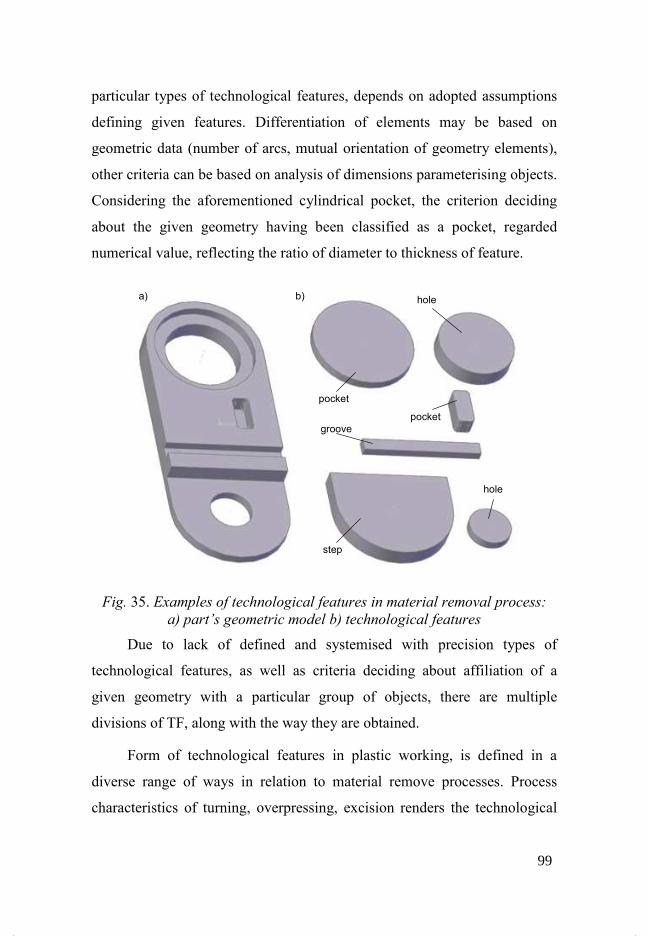
particular types of technological features, depends on adopted assumptions
defining given features. Differentiation of elements may be based on
geometric data (number of arcs, mutual orientation of geometry elements),
other criteria can be based on analysis of dimensions parameterising objects.
Considering the aforementioned cylindrical pocket, the criterion deciding
about the given geometry having been classified as a pocket, regarded
numerical value, reflecting the ratio of diameter to thickness of feature.
Fig. 35. Examples of technological features in material removal process:
a) part’s geometric model b) technological features
Due to lack of defined and systemised with precision types of
technological features, as well as criteria deciding about affiliation of a
given geometry with a particular group of objects, there are multiple
divisions of TF, along with the way they are obtained.
Form of technological features in plastic working, is defined in a
diverse range of ways in relation to material remove processes. Process
characteristics of turning, overpressing, excision renders the technological
a) b)
hole
groove
hole
step
99
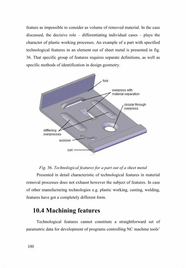
feature as impossible to consider as volume of removed material. In the case
discussed, the decisive role
character of plasti
technological features in an element out of sheet metal is presented in fig.
36. That specific group of features requires separate definitions, as well as
specific methods of
Fig. 36
Presented in detail characteristic of technological features in material
removal processes does not exhaust however the subject of features. In case
of other manufacturing technologies e.g. plastic working, casting, welding,
features have got a completely different form.
10.4 Machining features
Technological features cannot constitute a straightforward set of
parametric data for development of programs control
feature as impossible to consider as volume of removed material. In the case
discussed, the decisive role – differentiating individual cases
character of plastic working processes. An example of a part with specified
technological features in an element out of sheet metal is presented in fig.
36. That specific group of features requires separate definitions, as well as
specific methods of identification in design geometry.
36. Technological features for a part out of a
Presented in detail characteristic of technological features in material
removal processes does not exhaust however the subject of features. In case
other manufacturing technologies e.g. plastic working, casting, welding,
features have got a completely different form.
Machining features
Technological features cannot constitute a straightforward set of
parametric data for development of programs controlling NC machine tools’
feature as impossible to consider as volume of removed material. In the case
differentiating individual cases – plays the
c working processes. An example of a part with specified
technological features in an element out of sheet metal is presented in fig.
36. That specific group of features requires separate definitions, as well as
a sheet metal
Presented in detail characteristic of technological features in material
removal processes does not exhaust however the subject of features. In case
other manufacturing technologies e.g. plastic working, casting, welding,
Technological features cannot constitute a straightforward set of
ling NC machine tools’
100
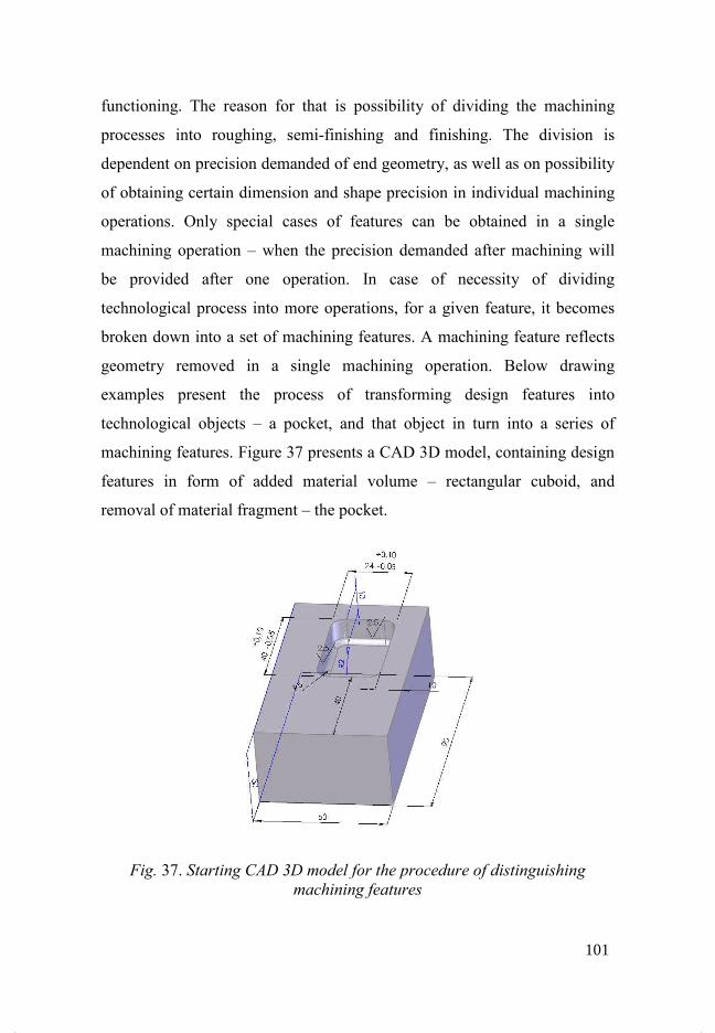
functioning. The reason for that is possibility of dividing the machining
processes into roughing, semi-finishing and finishing. The division is
dependent on precision demanded of end geometry, as well as on possibility
of obtaining certain dimension and shape precision in individual machining
operations. Only special cases of features can be obtained in a single
machining operation – when the precision demanded after machining will
be provided after one operation. In case of necessity of dividing
technological process into more operations, for a given feature, it becomes
broken down into a set of machining features. A machining feature reflects
geometry removed in a single machining operation. Below drawing
examples present the process of transforming design features into
technological objects – a pocket, and that object in turn into a series of
machining features. Figure 37 presents a CAD 3D model, containing design
features in form of added material volume – rectangular cuboid, and
removal of material fragment – the pocket.
Fig. 37. Starting CAD 3D model for the procedure of distinguishing
machining features
101
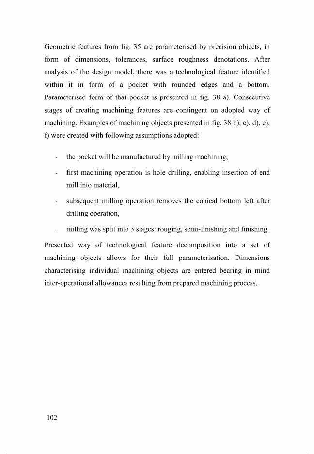
Geometric features from fig. 35 are parameterised by precision objects, in
form of dimensions, tolerances, surface roughness denotations. After
analysis of the design model, there was a technological feature identified
within it in form of a pocket with rounded edges and a bottom.
Parameterised form of that pocket is presented in fig. 38 a). Consecutive
stages of creating machining features are contingent on adopted way of
machining. Examples of machining objects presented in fig. 38 b), c), d), e),
f) were created with following assumptions adopted:
- the pocket will be manufactured by milling machining,
- first machining operation is hole drilling, enabling insertion of end
mill into material,
- subsequent milling operation removes the conical bottom left after
drilling operation,
- milling was split into 3 stages: rouging, semi-finishing and finishing.
Presented way of technological feature decomposition into a set of
machining objects allows for their full parameterisation. Dimensions
characterising individual machining objects are entered bearing in mind
inter-operational allowances resulting from prepared machining process.
102
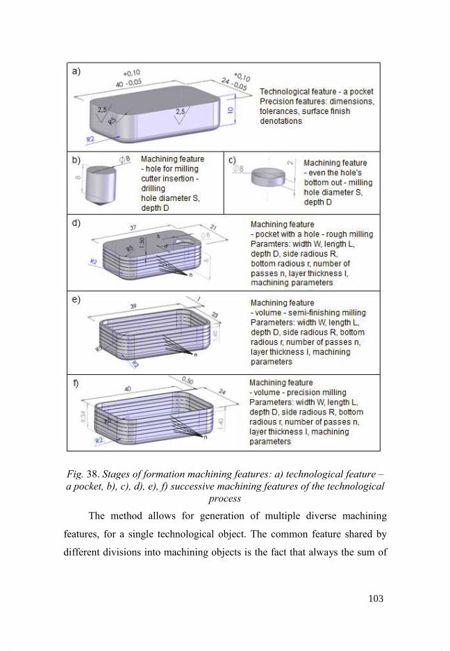
Fig. 38. Stages
a pocket, b),
The method allows for generation of multiple diverse machining
features, for a single technological object. The common feature shared by
different divisions into machining object
Stages of formation machining features: a) technological
b), c), d), e), f) successive machining features of
process
The method allows for generation of multiple diverse machining
features, for a single technological object. The common feature shared by
different divisions into machining objects is the fact that always the sum of
technological feature –
of the technological
The method allows for generation of multiple diverse machining
features, for a single technological object. The common feature shared by
s is the fact that always the sum of
103
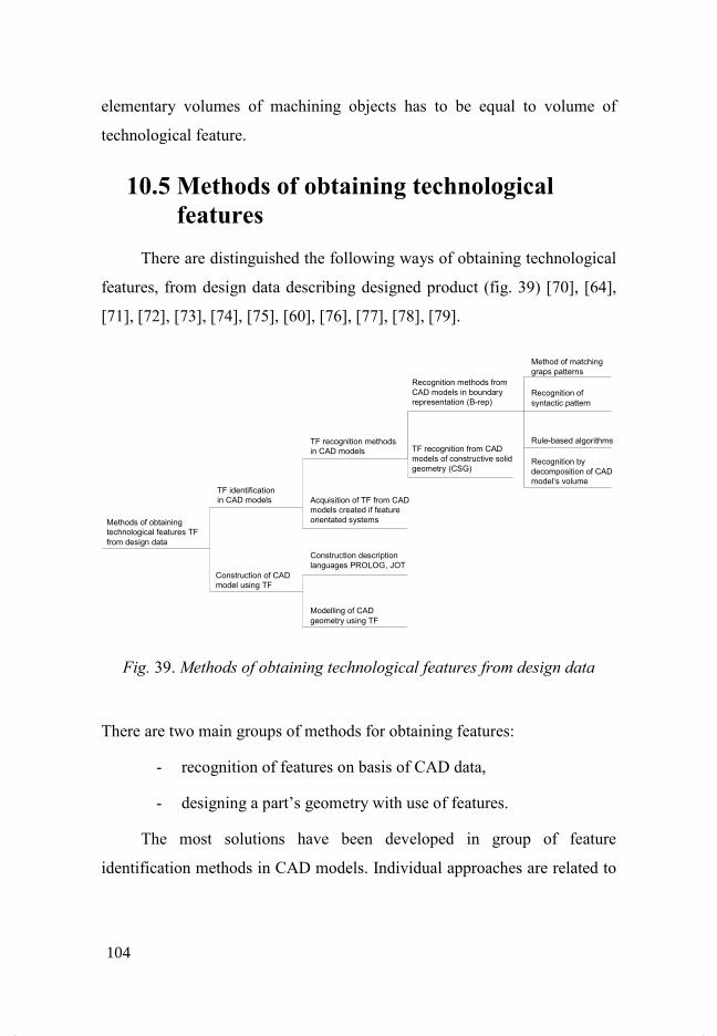
elementary volumes of machining objects has to be equal to volume of
technological feature.
10.5 Methods of obtaining technological
features
There are distinguished the following ways of obtaining technological
features, from design data describing designed product (fig. 39) [70], [64],
[71], [72], [73], [74], [75], [60], [76], [77], [78], [79].
Fig. 39. Methods of obtaining technological features from design data
There are two main groups of methods for obtaining features:
- recognition of features on basis of CAD data,
- designing a part’s geometry with use of features.
The most solutions have been developed in group of feature
identification methods in CAD models. Individual approaches are related to
Recognition methods from
CAD models in boundary
representation (B-rep)
Method of matching
graps patterns
TF recognition methods
in CAD models TF recognition from CAD
models of constructive solid
geometry (CSG)
Construction of CAD
model using TF
TF identification
in CAD models
Methods of obtaining
technological features TF
from design data
Acquisition of TF from CAD
models created if feature
orientated systems
Construction description
languages PROLOG, JOT
Modelling of CAD
geometry using TF
Recognition of
syntactic pattern
Rule-based algorithms
Recognition by
decomposition of CAD
model’s volume
104

the way of representing geometry in CAD computer systems: boundary
representation, Constructive Solid Geometry CSG.
10.5.1 Languages of describing construction form
Designing an item’s geometry with use of techniques, allowing for
direct usage of geometric data in the process of developing technology, is a
troublesome activity, because of imposing on the constructor specific
instructions regarding designing. Such requirements are posed before the
constructor – in methods of describing an item’s geometry – by languages
of construction description.
Examples of such languages are:
- JOT – developed in Institute of Technological Engineering and
Production Automation of Cracow University of Technology under
the direction of prof. A. Samek,
- PROLOG (fr. PROgrammation en LOGique) – programming in
logic – high level programming language based on logic.
The JOT language uses the method of obtaining an item’s geometry
through revolution about the axis or contour extrusion along so-called
“driving curve”. The principle of building a part’s geometry is depicted by
fig. 40 [56]. During definition of contours, it is possible to define parameters
necessary for development of technological process plans such as:
roughness, hardness, shape and position deviations.
105

Fig. 40. The idea of modelling a part’s geometry in the JOT language [56]
Usage of the PROLOG language in the scope of elaborating a set of
design data for needs of manufacturing technology planning is concentrating
on definition of features in that language, which are used for describing
designed parts. An example of representation of features in the PROLOG
language in presented in fig. 41 [80].
106
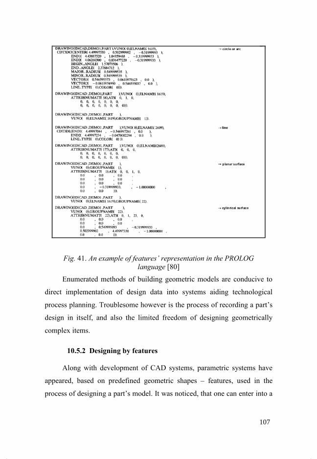
Fig. 41. An example of features’ representation in the PROLOG
language [80]
Enumerated methods of building geometric models are conducive to
direct implementation of design data into systems aiding technological
process planning. Troublesome however is the process of recording a part’s
design in itself, and also the limited freedom of designing geometrically
complex items.
10.5.2 Designing by features
Along with development of CAD systems, parametric systems have
appeared, based on predefined geometric shapes – features, used in the
process of designing a part’s model. It was noticed, that one can enter into a
107
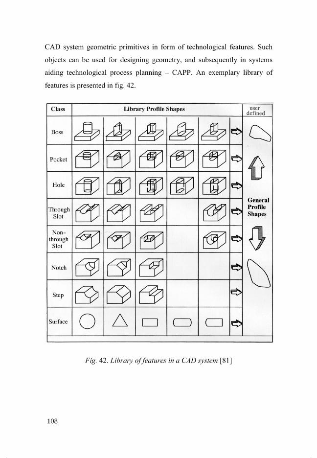
CAD system geometric primitives in form of technological features. Such
objects can be used for designing geometry, and subsequently in systems
aiding technological process planning – CAPP. An exemplary library of
features is presented in fig. 42.
Fig. 42. Library of features in a CAD system [81]
108
Library of features was used in a prototype CAD system, based on
core of ACIS solid modelling [81]. The system allows for designing
geometry by:
- inserting features from the library,
- assigning values to object parameters,
- revolving,
- extruding,
- adding tolerances,
- defining dependencies parent – child,
- building complex features.
An item’s geometry represented in that way, with use of features, can
serve as a set of input data to a CAPP system. Shortcoming of presented
method of obtaining features is the limited number of features saved in the
library, available in the process of modelling geometry. Possibility of
adding own features had been permitted, although in case of using that data
in a CAPP system, entered objects are not going to be identified at the stage
of process planning due to lack of information about standards for
recognition.
10.5.3 AAG graph methods (Attributed Adjacency Graph)
Recognition of features, reliant on AAG graph analysis is based on an
item’s geometry saved in boundary representation B-Rep. Geometry saved
in that way is converted into an AAG graph. Surfaces of a CAD model are
reflected in form of graph nodes, connections between nodes have got
attributes assigned and they reproduce geometry edges [82], [83], [84], [85].
109
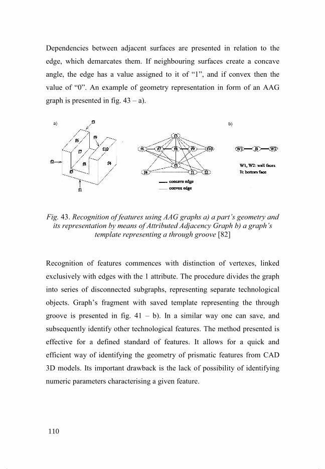
Dependencies between adjacent surfaces are presented in relation to the
edge, which demarcates them. If neighbouring surfaces create a concave
angle, the edge has a value assigned to it of “1”, and if convex then the
value of “0”. An example of geometry representation in form of an AAG
graph is presented in fig. 43 – a).
Fig. 43. Recognition of features using AAG graphs a) a part’s geometry and
its representation by means of Attributed Adjacency Graph b) a graph’s
template representing a through groove [82]
Recognition of features commences with distinction of vertexes, linked
exclusively with edges with the 1 attribute. The procedure divides the graph
into series of disconnected subgraphs, representing separate technological
objects. Graph’s fragment with saved template representing the through
groove is presented in fig. 41 – b). In a similar way one can save, and
subsequently identify other technological features. The method presented is
effective for a defined standard of features. It allows for a quick and
efficient way of identifying the geometry of prismatic features from CAD
3D models. Its important drawback is the lack of possibility of identifying
numeric parameters characterising a given feature.
110
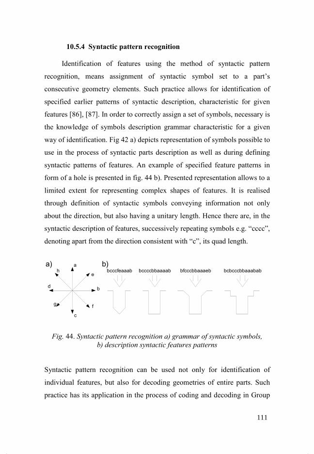
10.5.4 Syntactic pattern recognition
Identification of features using the method of syntactic pattern
recognition, means assignment of syntactic symbol set to a part’s
consecutive geometry elements. Such practice allows for identification of
specified earlier patterns of syntactic description, characteristic for given
features [86], [87]. In order to correctly assign a set of symbols, necessary is
the knowledge of symbols description grammar characteristic for a given
way of identification. Fig 42 a) depicts representation of symbols possible to
use in the process of syntactic parts description as well as during defining
syntactic patterns of features. An example of specified feature patterns in
form of a hole is presented in fig. 44 b). Presented representation allows to a
limited extent for representing complex shapes of features. It is realised
through definition of syntactic symbols conveying information not only
about the direction, but also having a unitary length. Hence there are, in the
syntactic description of features, successively repeating symbols e.g. “cccc”,
denoting apart from the direction consistent with “c”, its quad length.
Fig. 44. Syntactic pattern recognition a) grammar of syntactic symbols,
b) description syntactic features patterns
Syntactic pattern recognition can be used not only for identification of
individual features, but also for decoding geometries of entire parts. Such
practice has its application in the process of coding and decoding in Group
a
b
c
d
he
fg
bcccfeaaab bccccbbaaaab bfcccbbaaaeb bcbcccbbaaabab
a) b)
111

Technology. An application example of syntactic pattern recognition for
elements out of a sheet metal is presented in fig. 45
Fig. 45.
The method of feature identification based on syntactic pattern has got a
limited application due to the representation of planar geometry
Reading of dimensional parameters is ambiguous. There is an inability
transferring information holding technological characteristics describing a
part’s geometry.
10.5.5
In rule
constructed in form of conditions and conclusions: if
Individual rules represent patterns of particular features
During the analysis of a part’s geometry, usually in form of boundary
representation B
verified. If all conditions, for a given feature, are satisfied, it becomes
chnology. An application example of syntactic pattern recognition for
elements out of a sheet metal is presented in fig. 45 [88].
Representation of syntactic pattern for a part
metal [88]
The method of feature identification based on syntactic pattern has got a
limited application due to the representation of planar geometry
Reading of dimensional parameters is ambiguous. There is an inability
transferring information holding technological characteristics describing a
part’s geometry.
10.5.5 Rule-based algorithms – logic approach
In rule-based methods, features are identified with use of rules
constructed in form of conditions and conclusions: if – then
Individual rules represent patterns of particular features
During the analysis of a part’s geometry, usually in form of boundary
representation B-Rep, the correctness of conformity of rules’ conditions is
verified. If all conditions, for a given feature, are satisfied, it becomes
chnology. An application example of syntactic pattern recognition for
part out of a sheet
The method of feature identification based on syntactic pattern has got a
limited application due to the representation of planar geometry – 2D.
Reading of dimensional parameters is ambiguous. There is an inability of
transferring information holding technological characteristics describing a
logic approach
based methods, features are identified with use of rules
then – else clauses.
Individual rules represent patterns of particular features [87], [88], [89].
During the analysis of a part’s geometry, usually in form of boundary
Rep, the correctness of conformity of rules’ conditions is
verified. If all conditions, for a given feature, are satisfied, it becomes
112

identified within the system. In work [89] are presented exemplary rules
defined for the process of groove identification:
“Find Linear Slot Rule
SEARCH During Hint Cycle for:
A planar, nonstock face of the
A second planar, nonstock face
Delta Volume
of the Delta Volume,
not equal to, but parallel
and opposing to the first
face
NOT( A previously created linear
slot using these two faces)
THEN
Extend feature in all directions
Search for slot floors
Classify feature along, and
perpendicular to,
the sweep directions
Evaluate classification for partial verification” [89]
In described method of feature identification, for processing rules
describing features often expert systems had been used. Due to the character
of processed information, it is difficult to write rules for features having
common parts.
10.5.6 Recognition from neutral format of STEP data exchange
STEP data exchange standard, defined in the international ISO 10303
norm, contains information about a part’s geometry, along with
technological data. The possibility of using that standard for identification
of technological features had been noticed.
113
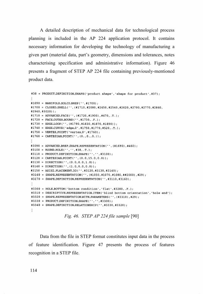
A detailed description of mechanical data for technological process
planning is included in the AP 224 application protocol. It contains
necessary information for developing the technology of manufacturing a
given part (material data, part’s geometry, dimensions and tolerances, notes
characterising specification and administrative information). Figure 46
presents a fragment of STEP AP 224 file containing previously-mentioned
product data.
Fig. 46. STEP AP 224 file sample [90]
Data from the file in STEP format constitutes input data in the process
of feature identification. Figure 47 presents the process of features
recognition in a STEP file.
114
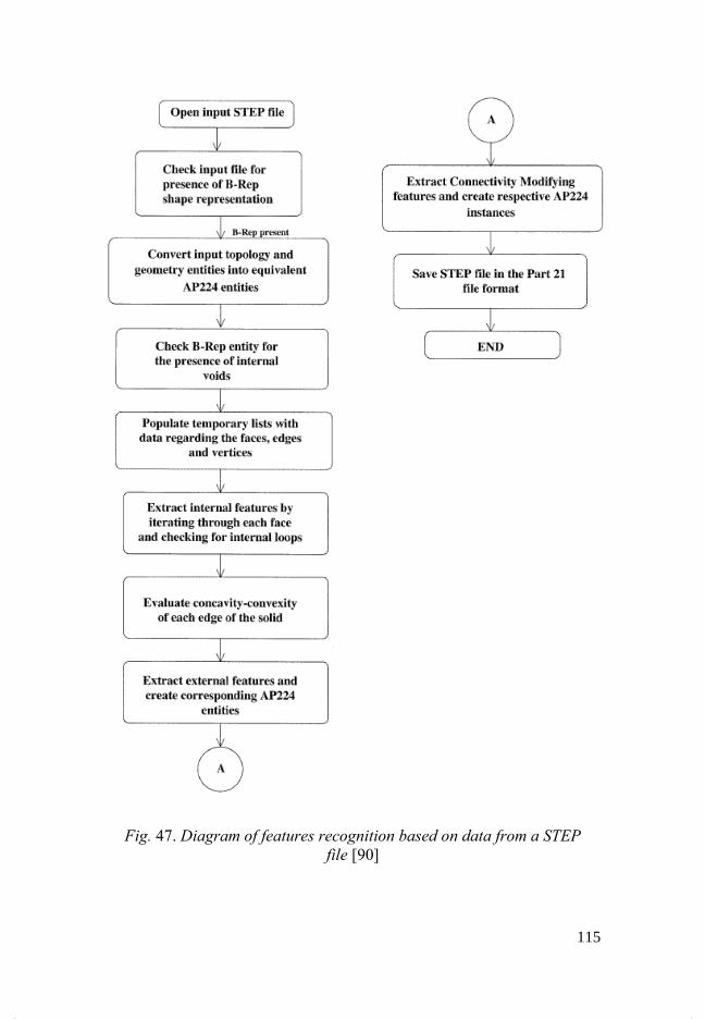
Fig. 47. Diagram of features recognition based on data from a STEP
file [90]
115
After loading the STEP file, saved in AP 202 application protocol
verification takes place, whether the file contains data describing geometry
in boundary representation. If the file does not contain data about geometry,
there is no topological information either, which is necessary in the process
of features identification. In that case the system stops operating, informing
the user, that a given file cannot be further analysed. If information about
geometry is correctly saved in input file, the process is initiated of
conversing geometry and topology of parts from the AP 202 format into
objects characteristic for AP 224. Then the process of features recognition
from geometric and topologic data in AP 224 format starts.
After recognition of features, the data is saved in “Part 21” format,
which can be loaded by different CAD systems, or constitute the format of
input data for CAPP systems, in order to develop manufacturing technology
of a given part [90].
Presented method of features recognition from data saved in the STEP
format, characterises with an unquestionable advantage due to the fact of
using formalised data exchange standard. Problematic however is
representation of data characterising individual features, because the STEP
norm is still being supplemented with new application protocols and so far
not all its modules have been developed yet.
Discussed methods of features recognition constitute only a part out of
many, which have been developed within the confines of research. Along
with development of computer techniques aiding designing, the methods
based on construction description languages and syntactic representation are
currently loosing importance. The majority of nowadays developed
recognition methods are based on an item’s geometry saved in form of a
CAD 3D model.
116
11 Knowledge representation methods used in CAPP
There are three methods of knowledge representation, which derive
from theories describing information processing by humans:
- semantic networks,
- rules,
- frames.
The last two methods of knowledge representation allow for building
expert systems. Most commonly and the longest used, has been the rule
representation. By means of rules one can record knowledge regarding
solutions of fundamental problems related to technological planning,
especially:
- recognition of technological features,
- assignment of machining operations to individual TF,
- determination of TF machining order.
Alongside rule representation, the second most popular is frame
representation, referring to mechanisms of processing knowledge by
humans, which is described in the following subsection.
11.1 Frame representation The fundamental element of data structure in frame representation is a
so-called frame. The frame represents notions, situations and concepts. The
author of frame concept - Minsky [91] claims, that when a human
encounters a new situation, he recalls from memory the structure called a
frame. Frame is a memorised structure, whose some elements can be
117
modified in need, in order to adopt it to reality description. Frame stores
information in so-called slots. A slot is constructed similarly to a structure in
C/C++ language or to a record in Pascal language. In general, the frame
representation resembles object representation, which can be treated as a
computer implementation of frame representation [92]. Similarly as in
object representation, also in systems using frame representation the notion
of class and class intention is introduced. Hence there are frames being
classes i.e. certain patterns describing a given object or notion, which have
required for the description slots adopting particular values and frames
being class instances describing a specified object or notion. With the notion
of class is connected inheritance, facilitating definition of classes having
usually all slots and facets of another class or classes. Individual slots are
storing information of a particular type, likewise the variables in procedural
languages do. Slots can also store sets of rules or procedures used for
determination of a slot’s value. A special case of a slot is a slot indicating to
a frame. By means of such slots one can build a hierarchical structure.
Moreover, slots can have default values, so the ones which are assigned to
them once a certain frame is created (it can be compared to declaration with
simultaneous variables initialisation in procedural programming languages).
Additionally, the very same slot can belong to an excess of one frame and
this is a fundamental difference compared to object paradigm. Properties of
slots can be additionally described by means of so-called facets. Facets can
i.a. impose restrictions on acceptable slot values, they can be used for
obtaining values of slots or inform the inference mechanism how to process
a particular slot. Typical examples of facets are those called in particular
situations such as: slot’s value change (is-changed) and request of using a
slot’s value – (is-needed). The Is-needed facet is used in the situation when
a slot’s value is required to solve a problem, and its value is not determined.
118

In general, problem solving in expert systems using frame representation
takes place in principle through calling methods attached to slots, what
differentiates them from rule-based systems, which use for that purpose the
inference engine and rules.
11.2 Rule representation Rule representation is one of the most popular and the oldest methods
of knowledge representation used for building expert systems [31]. In the
sixties of the XX century it was proved, that in the majority of cases, the
human reasoning can be presented by means of rules [93]. In the rule
paradigm, rules represent heuristics, or so-called rules of thumb, which
determine the set of actions performed in a certain situation. The elementary
rule is composed of two parts:
- conditional part, containing list of conditions (premises),
- consequent part, containing list of conclusions.
Hence the basic rule can be written as [94]:
if premise then conclusion
Conditions describe a situation – state of object traits, which render the rule
feasible. Generally, rules refer to long-term memory and describe
dependencies which do not change over a short time span. Individual
conditions are linked with logic operators, determining combinations of
values of individual attributes, for which the rule is feasible. In turn the
knowledge representing the short-term memory – current parameters of an
analysed object or problem – is represented by means of facts. Facts usually
adopt a form of trio <object, attribute, value>, or due <attribute, value>. In
practical realisations of expert systems, facts resemble initiated variables –
they have values of a particular type. On the other hand, the premises of
119
rules do not have to refer to a single value, but they can define intervals of
values for which the rule is feasible (in case of numeric facts). The effect
following from a rule’s execution is occurrence of a new fact or facts in the
database. New facts in turn, can render possible execution of subsequent
rules.
11.3 Expert systems
Expert systems are one of artificial intelligence methods [95]. They
had been developed in the middle of the sixties of the XX century [96].
They are computer programs, which store knowledge from a specified, well
documented area and allow for its usage in order to solve problems without
an expert’s participation [95]. The idea behind building and functioning of
expert systems is based on acquisition of knowledge from an expert, saving
it in a knowledge base and permitting access to that knowledge to persons
seeking solution to a particular problem. The knowledge acquisition
requires cooperation between the domain expert and the so-called
knowledge engineer building and supplementing the knowledge base of an
expert system. According to some authors, the process of knowledge
acquisition constitutes the most significant bottleneck during
implementation of expert systems [97] in comparison to other methods of
artificial intelligence, such as e.g. artificial neural networks. Operation of an
expert system reminds an expert consultation also in that respect, that if
necessary the system asks about required, lacking information, and explains
why certain information is vital when solving a certain problem. In order for
building knowledge bases of an expert system to be justified, the problem
pending solution, should satisfy the following conditions [95]:
- knowledge from a given area needs to be precisely determined,
120
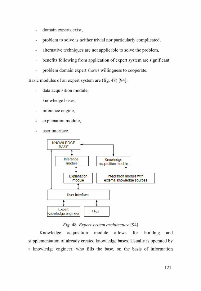
- domain
- problem to solve is neither trivial nor particularly complicated,
- alternative techniques are not applicable to solve the proble
- benefits following from application of expert system are significant,
- problem domain expert shows willingness to cooperate.
Basic modules of an expert system are (fig. 48)
- data acquisition module,
- knowledge bases,
- inference
- explanation module
- user interface.
Knowledge acquisition modu
supplementation of already
a knowledge engineer, who fills the base, on the basis of information
domain experts exist,
problem to solve is neither trivial nor particularly complicated,
alternative techniques are not applicable to solve the proble
benefits following from application of expert system are significant,
problem domain expert shows willingness to cooperate.
Basic modules of an expert system are (fig. 48) [94]:
data acquisition module,
knowledge bases,
erence engine,
explanation module,
user interface.
Fig. 48. Expert system architecture [94]
Knowledge acquisition module allows for
supplementation of already created knowledge bases. Usually is operated by
a knowledge engineer, who fills the base, on the basis of information
problem to solve is neither trivial nor particularly complicated,
alternative techniques are not applicable to solve the problem,
benefits following from application of expert system are significant,
problem domain expert shows willingness to cooperate.
[94]
le allows for building and
knowledge bases. Usually is operated by
a knowledge engineer, who fills the base, on the basis of information
121

obtained from a domain expert. A knowledge base contains knowledge
regarding current parameters of an object and knowledge describing
proceedings in certain situations (in rule-based systems it is a set of rules).
In rule-based expert systems, the element responsible for verification of
facts conformity with standards included in antecedent and with execution
of conclusions from the consequent is the so-called inference engine. Based
on comparison between facts and premises, the inference engine determines
feasibility of rules. Following from execution of rules, the knowledge bases
are supplemented with new facts.
There are two fundamental types of reasoning [94]:
- forward chaining,
- backward chaining.
Forward chaining is also called data-driven chaining [94]. The
inference engine analyses, which premises of rules are possible to confirm.
As a result of executing a rule in the knowledge base new facts appear, what
can lead to confirmation of other rules. The process is repeated until the
moment neither rule can be confirmed. This method’s trait is expansion of
fact base [94]. New facts can occur in the base not only as a result of rules’
execution, but also they can be added by the user prior to reasoning process
commencement. The process of forward chaining can be compared with
issuing diagnosis (conclusion) based on symptoms (facts).
Backward chaining in turn runs into opposite direction. It starts with
definition of hypothesis, which similarly to a fact adopts the form of trio
<OAV>. The purpose of backward chaining is confirmation, or negation of
a hypothesis. The inference engine verifies the feasibility of rules, which
contain conclusion corresponding to hypothesis. Confirmation of premises
of some rules might require verification of other rules, which in conclusion
122

contain facts needed for confirmation of premises of the rule analysed. If
there are facts lacking from the knowledge base and they cannot be obtained
by calling other rules, the system can proceed to conversation with user.
Backward chaining is also called goal-driven chaining [94]. The inference
engine is responsible also for determination of rule execution order, in case
when existing facts allow for execution of more than one rule at a time.
Different strategies can be used here, e.g.: determination of rule priorities,
deletion from the list of rules one has already used, or usage of the most
frequently used rules. The explanation module is responsible for explaining
to user, when the system has drawn certain conclusions – performed
conclusion.
11.3.1 Tools for building expert systems
Expert systems can be created from scratch, just like other computer
programs using various programming languages, universal ones such as C,
Pascal etc to start with, and more appropriate symbolic languages like Lisp
or Prolog or languages for building expert systems like CLIPS. They can
also be created using dedicated tools such as shell expert systems or meta-
expert systems. Shell systems are programs with implemented inference
engine and explanation module, but with empty knowledge base. Meta
systems are in turn expert systems intended for building expert systems
[66]. Examples of shell systems are the Jess system and PC – Shell. The
most popular programming languages used for implementation of issues
related to artificial intelligence are:
- CLIPS (C Language Integrated Production System),
- PROLOG (fr. PROgrammation en LOGique),
- LISP (LISt Processing) – functional programming.
123

Prolog is a language of logic programming using the backward
chaining mechanism. LISP in turn has not an in-built inference engine, but it
can be easily implemented in it. A program written in the LISP language
consists of lists being ordered element sequences. Those elements can be
both functions, names, numbers and other lists. In turn the most simple in
use and at the same time created with building of expert systems in mind, is
the CLIPS. Due to built-in strategies of solving conflicts between rules, and
implemented inference engine, it is going to be discussed in broader
manner.
The CLIPS was initially a rule-based language using forward
chaining. Later it had been developed i.a. with paradigms; procedural and
object [98], [99]. The fundamental form of data representation in that
language are facts, stored in the fact-list. Facts are used by rules in the
process of reasoning. They adopt one of two forms: ordered and non-
ordered. Ordered facts are composed of a symbol and any number of fields
separated with spaces. Wherein a fact consisting of only a symbol is
acceptable. Usually the first field is a symbol denoting relation, which refers
to remaining fields. Fields can be of one of fundamental types, apart from
the first one, which is a symbol.
In turn objects in the CLIPS language can be of one of two kinds: one of
fundamental types or an instance of class defined by user.
An important element of the language is the so-called agenda, so the list of
non-executed rules, whose conditions are satisfied. The order of rules on the
agenda is decisive of their verification order. The rule on top is executed
first. When the rule makes the agenda, the following factors are deciding
about its position:
124
- the rule is located above rules of lower priority (salience) and below
rules of higher priority,
- after determination of order amongst the rules of the same priority,
the current strategy of solving conflicts is used (described below),
- in case when a rule is activated through insertion or deletion of a fact
and its position on the agenda is impossible to determine on the basis
of two above-mentioned criteria, the position is determine
arbitrarily.
CLIPS has seven strategies of resolving conflicts (depth, breadth, simplicity,
complexity, lex, mea, random) used for determining the order of executing
rules of the same priority. Change in strategy causes alteration in order of
executing rules on the agenda according to the new strategy. The default
strategy is depth. In the depth strategy, newly activated (added to agenda)
rules are located below rules of the same priority. In the simplicity the rule
is situated above rules of the same of greater specificity (within the bounds
of rules of the same priority). Specificity of a rule is determined based on
number of comparisons, which have to be made within the left side of the
rule (the conditional part of a rule). Every comparison to the constant
increases the value of specificity by one, similarly as every function calling
does. Boolean functions do not increase the value of specificity, contrary to
their arguments. In the complexity strategy, a newly activated rule is situated
above rules of lower or equal specificity (within the bounds of rules of the
same priority). In the random strategy, every rule activation has got a
random number assigned, which is later used for determining the position of
the rule within the rule of the same priority. That number does not change
even after change in strategy, therefore the same order of rules will be
restored, once the random strategy is chosen again.
125
LEX strategy corresponds to strategy of the same name in OPS5 language.
In the first place the recency of the pattern is checked, which activated the
rule in order to determine the location of the rule. Every fact has got a
timetag assigned, which stores relative addition time. Relative timetag value
indicates, that the given element was added later.
Determination of new position for a new rule on agenda, amongst rules of
the same priority, requires sorting every rule’s pattern entities according to
the timetag value in descending order. Activated rule with newer patterns is
situated before rules, whose patterns are older. If that comparison is
inconclusive, that is when timetag values are identical, then the priority is
held by the rule of higher quantity of those tags. If both rules are the same in
that respect either, then the rule positioned higher is the one of higher
specificity value.
The last strategy is MEA, an analogous strategy exists in the OPS5
language. The activated rule, whose first timetag is greater, is situated
before the rule of smaller first timetag. If that comparison is inconclusive,
the LEX strategy is used next.
11.3.2 Shell expert systems
Shell expert system is a computer program, which is intended to
simplify and shorten the time of building an expert system. It is a finished
expert system without a knowledge base [66], [100]. Shell expert system
allows for concentrating on building of the knowledge base, because it has
inference engine and explanation module implemented, and usually
graphical editor of knowledge base. An example of shell expert system is
the software included in the SPHINX artificial intelligence suite from the
AITECH company [101].
126

Building an expert system takes place with use of the following two
programs:
- CAKE – a program which has amongst others knowledge base editor
(attributes, facts, rules) and editor of the control block (fig. 49),
- PC – Schell – shell expert system. It allows for using knowledge
bases built by means of the CAKE tool.
Fig. 49. CAKE – editing rules [102]
The SPHINX suite uses rule-based knowledge representation [103]. It
allows for creating facts composed of trios <OAV> as well as duos <AV>.
Attributes can be defined as symbolic, storing alphanumeric sets as well as
numeric – storing numbers. Acceptable values of attributes can be restricted
by intervals or lists of permitted values. Moreover there is a possibility of
defining the attribute’s type as a so-called some-of, which permits existence
in the knowledge base in of more than one fact composed of the same
elements <OA>, but differing in value.
All allowed types of attributes are presented in fig. 50.
127

Fig. 50. Available types of attributes in the Sphinx system from AITECH
Sphinx
SPHINX supports both backward and forward inference engine. Knowledge
can be additionally divided into so-called tables. SPHINX possess an in-
built language allowing for i.a. writing control programs, responsible for
usage of the knowledge base and controlling the course of dialog with the
user. One can use the built into PC-Shell expert systems also from the level
of different programs by using either OLE or DDE mechanism.
11.3.3 Knowledge processing in rule-based expert systems
Based on rule-based models are many available shell systems and
other tools aiding building expert systems. Below were described main
problems and constraints related to application of that model of knowledge
representation in aiding works connected to technology planning.
In rule-based expert systems the effect of confirmation of a rule’s
premise – during forward chaining – is addition to the knowledge base of a
new fact – such practice takes place amongst others, in PC-Shell shell expert
system. In the CLIPS language there is a possibility of adding several facts
128

within conclusion of a single rule. In the PC-Shell system such fact can be
obtained through creation of extra rules with the same block of conditions,
but other conclusions. Effectively, during backward chaining the number
and type of added facts is not always easy to predict, because it is not only
dependent on initial facts, but also on the number and content of the rules.
In case of backward chaining which concludes with a hypothesis
confirmation, in the knowledge base a fact defined in hypothesis is not
going to occur. On the other hand, facts can be added which result from e.g.
the dialog with user, necessary for hypothesis confirmation. In case of
hypothesis being not confirmed, the user is not informed about reasons of
that situation coming about, because there are several possible:
- Lack of one or more facts required by the rules’ premises – the
situation takes place, if there is a rule, whose conclusion resembles
the hypothesis, but the inference mechanism is not able to confirm it,
due to the lack of at least one fact determined in premises.
- In the knowledge base there are facts rendering impossible to
execute rules – attributes describing an object, appearing in the
premise of the rule capable of confirming the hypothesis, they exist
and have particular values, but their values do not resemble the
premises. E.g. one of rule’s premise requires a fact in form of the
following trio:
(part model, mass, 3.5),
but there is a fact in the knowledge base:
(part model, mass, 3.8),
and there are not any other facts composed of the duo <part model,
mass>.
129
- The hypothesis describes the case, which cannot take place. Such
situation may occur, when hypothesis contains the fact, which does
not appear in conclusion of neither of rules and it is not possible to
obtain it by way of conversation. The second case is often
theoretical, because in practice operation of an expert system aims at
determining a parameter demanding usually complex reasoning, if
that value was possible to obtain by way of conversation, with
searching through rules, it itself should not be the reason for building
an expert system.
- Wrong hypothesis – a hypothesis has usually the form of an
alphanumeric set containing the quality symbol, determining in such
ways the expected value of the attribute. In case of an error in that
set, being for example alteration of character in the name of the
attribute, the inference mechanism will inform about the lack of
possibility to confirming the hypothesis.
Lack of feedback information in the event of hypothesis being disconfirmed,
sometimes forces the time-consuming knowledge base searching. The user
of the finished system can interpret it as negation of the hypothesis, and that
is only one of possible causes of such situation.
Coupled with rule-based expert systems is knowledge representation
in form of trios <object, attribute, value>. The knowledge base contains a
set of facts consisting of <OAV> trios. In the SPHI$X/PC-Schell shell
system a fact can be also constituted by the <AV> duo. The attribute of the
<OAV> notation resembles a variable, because it has a type, it differs from
it with the possibility of restricting acceptable values, what is missing from
the variables of simple type. In turn the object is the first element of the trio
<OAV> is the subject of analysis/diagnosis, and not an occurrence
130

(instance) of a particular class as it is in the case of object programming. An
object cannot inherit properties from other objects, neither can it be linked
with other objects with the parent-descendent relation. It renders impossible
to create a hierarchical structure, which is required at many stages of a
generative CAPP system’s functioning, amongst others for presentation of a
part’s model structure in boundary representation. A model consists of
separate geometric objects, which consist of faces, which in turn are
described by surfaces and loops etc. until the required level of detail.
Similarly a technological process consists of operations, occurring within
their procedure’s bounds etc. Hence the application of rule-based expert
systems is limited to aid the process of making rudimentary decisions. An
example of such decision is selection of a tool base on traits of a single
feature.
The next problem, connected to rule-based model of knowledge
representation, is lack of possibility to enter openly into the base several
objects of the same type. This constraint causes problems at the majority of
decision stages connected to technological process planning. For instance, at
the stage of processing CAD data there is any number of faces and other
geometry elements of a model of the same type. Groups of faces should be
transformed into technological objects, based on their traits as well as
geometric relations between them. However in representation based of
<OAV> trios the rule is strictly related to a particular object (object name)
or objects. Moreover, at some stages of a CAPP system operation the order
of facts is vital, especially at the stage of identification and sequencing of
machining operations. In rule-based systems there is no mechanism for
managing the order of facts, therefore the issue of realising sequencing does
not come easily in those system.
131
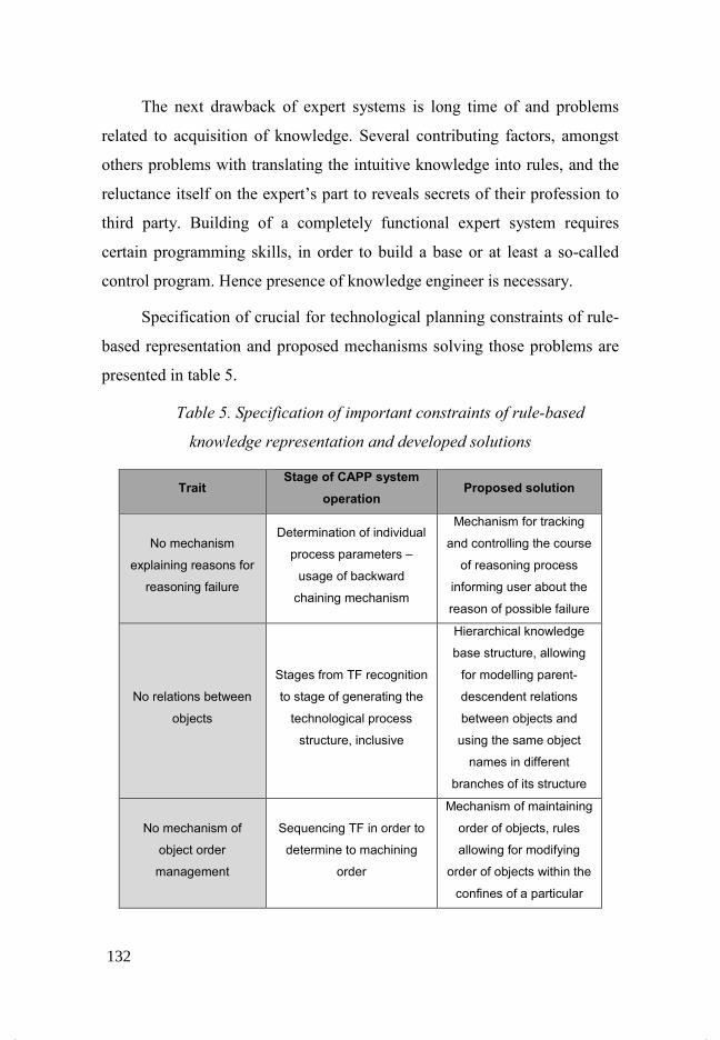
The next drawback of expert systems is long time of and problems
related to acquisition of knowledge. Several contributing factors, amongst
others problems with translating the intuitive knowledge into rules, and the
reluctance itself on the expert’s part to reveals secrets of their profession to
third party. Building of a completely functional expert system requires
certain programming skills, in order to build a base or at least a so-called
control program. Hence presence of knowledge engineer is necessary.
Specification of crucial for technological planning constraints of rule-
based representation and proposed mechanisms solving those problems are
presented in table 5.
Table 5. Specification of important constraints of rule-based
knowledge representation and developed solutions
Trait Stage of CAPP system
operation Proposed solution
No mechanism
explaining reasons for
reasoning failure
Determination of individual
process parameters –
usage of backward
chaining mechanism
Mechanism for tracking
and controlling the course
of reasoning process
informing user about the
reason of possible failure
No relations between
objects
Stages from TF recognition
to stage of generating the
technological process
structure, inclusive
Hierarchical knowledge
base structure, allowing
for modelling parent-
descendent relations
between objects and
using the same object
names in different
branches of its structure
No mechanism of
object order
management
Sequencing TF in order to
determine to machining
order
Mechanism of maintaining
order of objects, rules
allowing for modifying
order of objects within the
confines of a particular
132
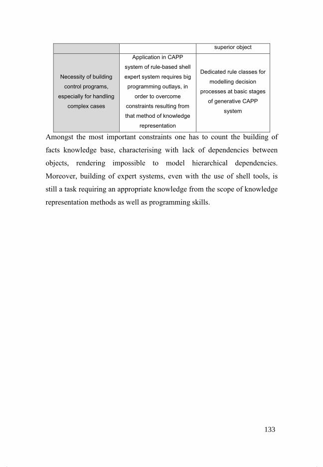
superior object
Necessity of building
control programs,
especially for handling
complex cases
Application in CAPP
system of rule-based shell
expert system requires big
programming outlays, in
order to overcome
constraints resulting from
that method of knowledge
representation
Dedicated rule classes for
modelling decision
processes at basic stages
of generative CAPP
system
Amongst the most important constraints one has to count the building of
facts knowledge base, characterising with lack of dependencies between
objects, rendering impossible to model hierarchical dependencies.
Moreover, building of expert systems, even with the use of shell tools, is
still a task requiring an appropriate knowledge from the scope of knowledge
representation methods as well as programming skills.
133
12 Summary
The issue of designing workplace arrangement plan is particularly
important, when a manufacturing system is subjected to reorganisation
(reconstruction), new workplaces are added or it is designed from scratch as
a new one. The way of allocating workplaces is influenced by substantial
number of factors. They were described in detail in chapters of hereof paper.
Application of computer techniques will allow for addressing the issue in a
broader respect and quicker obtainment of solution.
Creation of LAYOUT plans is a long-term task, very expensive and
every modification or change in hitherto state entails significant expenditure
and cannot be achieved without substantial outlays. Application of
information tools is capable of partly reducing the costs. Modelling and
testing solutions prior to their implementation into simulation programs
causes means of production to be used in a more effective manner.
Realisation of a complete spatial model, and its needs oriented adaptation
ensures an optimum utilisation of production space and abolishment of long
and intersecting transportation routes. Workplace allocation planning is
related to manufacturing technology intended for manufacturing given
machine parts or assemblies. Correctly developed technology takes into
account not only the specification of technological operations but also
contains specification of workplaces where those operations can be
executed. Workplace allocation should take into account the course of
process, thus those issues are strictly interconnected and changes in each of
those areas should be entered in parallel. CAPP computer systems aiding
technological process planning should take into account the possibility of
assigning alternative workplaces due to connection with LAYOUT planning
for realisation of manufacturing processes.
134
Bibliography
1. Sawik T. Optymalizacja dyskretna w elastycznych systemach
produkcyjnych. Warszawa : WNT, 1992.
2. Kral Z. Podstawy organizacji przygotowania produkcji. Wrocław :
WPW, 1985.
3. Heragu S. Facilities design. Boston : PWS Publishing Company, 1997.
4. Dileep R., Sule R. Manufacturing facilities location, planning and
design. Boston : PWS Publishing Company, 1994.
5. Sly D. P., Grajo, Montreuil E. Layout design & analysis software. Part
3 of a 3 part series published in IIE Solutions magazine. 1996.
6. Akturk Selim M., Wilson George R. A hierarchical model for the cell
loading problem of cellular manufacturing systems. I$T. J. PROD RES. 36,
1998, 7.
7. Jaumard B., Labit P., Riberio Celso C. A column generation approach
to cell formation problems in cellular manufacturing. Les Cahiers du
GERARD. 1999.
8. Filho Geraldo Ribeiro, Lorena Luiz Antonio -ogueira. A
constructive evolutionary approach to the machine-part cell formation
problem. [Online] 2010. http://www.lac.inpe.br/~lorena/enegep/AGC-CEll-
ene.
9. Irani J. A framework for cellular manufacturing evaluation process using
analytical and numerical techniques. Handbook of cellular manufacturing
systems. New York : John Wiley, 1999.
10. Durlik I. Inżynieria Zarządzania - Strategia i projektowanie systemów
produkcyjnych Cz.II. Warszawa : AWPlacet, 1996.
135
11. Chih-Ming Liu, Jiunn-Kuan Wu. Machine cell formation using the
simulated annealing algorithm. Computer Integrated Manufacturing. 6,
1993, 6.
12. Mungwattana A. Design of cellular manufacturing systems for dynamic
and uncertain production requirements with presence of routing flexibility.
Virginia : Blacksburn, 2000.
13. -eumann J. How to manufacture a new product competitively. 1999.
14. Choroszy B. Technologia maszyn. Wrocław : Politechnika Wrocławska,
2000.
15. Kurić I., Matuszak J., Debnar R. Computer aided process planning in
Machinery Industry. filia Bielsko – Biała : Politechnika Łódzka.
16. Liao T. Classification and coding approaches to part family formation
under a fuzzy environment. Fuzzy Sets and Systems. 2001, 122.
17. Holland P., Standring P., Long H., Mynors D. Feature extraction
from STEP (ISO 10303) CAD drawing files for metalforming process
selection in an integrated design system. Journal of Material Processing
Technology. 2002, 125-126.
18. Smolik D. P. Material requirements of manufacturing. New York : Van
Nostrand Reinhold Company, 1983.
19. Offodile O. F., Grznar J. Part family formation for FMS variety
reduction in flexible manufacturing systems. International Journal of
Operations & Production Managemen. 17, 1997, 3.
20. Koźmianski A.K., Piotrowski W. Zarządzanie - Teoria i praktyka.
Warszawa : WNT, 1997.
21. Muhlemann A. P., Oakland J. S., Lockyer K. G. Zarządzanie
produkcja i usługi. Warszawa : PWN, 1997.
136
22. Verma P., Ding F. A sequence-based materials flow procedure for
designing manufacturing cells. I$T. J.Prod.Res. 33, 1995, 12.
23. Santarek K. Lis S. Projektowanie rozmieszczenia stanowisk roboczych.
Warszawa : PWN, 1980.
24. Weiss Z., Dostatni E., Grajewski M. Zastosowanie symulacji
komputerowej do badania efektywności produkcji. V konferencja
Komputerowo zintegrowane zarządzanie, Zakopane. 2002.
25. Chlebus E., Duda J., Knosala R., Krzyżanowski J., Matuszek J.
Techniczne przygotowanie produkcji. Wiedza-Technika-Postęp, Prace
$aukowe Instytutu Technologii maszyn i Automatyzacji Politechniki
Wrocławskiej, Seria: Konferencje, $o. 78,. 2002.
26. Hales H. Lee. Computer-Aided Facilities Planning. Industrial
engineering. 1994, 9.
27. Sönemez A. I., Filiz I. H., DerelT., Baykasoglu A. An attempt to
modify Hillier's improvement algorithm for plant layout. SDU, Int. Journal
of Mechanical Engineering. 1996, 1.
28. Stępowski M. $owe techniki organizatorskie. Warszawa : PWN, 1997.
29. Chlebus E. Techniki komputerowe CAx w inżynierii produkcji.
Warszawa : Wydawnictwa Naukowo-Techniczne, 2000.
30. Cay F., Chassapis C. An IT view on perspectives of computer aided
process planning research. Computers in Industry. 1997, 34.
31. Sang C. Park. Knowledge capturing methodology in process planning.
Computer-Aided Design. 2003, 35.
32. Arezoo B., Ridgway K., Al-Ahmari A. M. A. Selection of cutting
tools and conditions of machining operations using an Expert System.
Computers in Industry. 42, 2000.
137
33. Kesheng Wang. An integrated intelligent process planning system
(IIPPS) for machining. Journal of Intelligent Manufacturing. 1998, 9.
34. Cichosz P. i inni. Obróbka skrawaniem wysoka efektywność. Wrocław :
Oficyna Wydawnicza Politechnika Wrocławska, 2007.
35. Etienne A., Dantan J. Y., Siadat A., Martin P. An improved appoach
for automatic process plan generation of complex boring. 2006, 57.
36. Zeid I. CAD/CAM Theory and Practice. s.l. : McGraw-Hill, Inc., 1991.
37. Piłot T. Zastosowanie sieci neuronalnych w technologii grupowej
elementów maszyn. rozprawa doktorska : Politechnika Śląska, Katedra
Technologii Maszyn i Zintegrowanych Systemów Wytwarzania, 2000.
38. Matuszek J., Smetana J. Pakiet oprogramowania do komputerowego
wspomagania projektowania procesów wytwarzania "SYSKLASS". Prace
naukowe ITMiA Politechniki Wrocławskiej, Seria Konferencje,
Automatyzacja Produkcji '97, Innowacje w technice i zarządzaniu. 1997.
39. Uniejewski J. Elementy systemu kompuerowo wspomaganego
projektowania procesów technologicznych wałków zębatych. Konferencja
$aukowo-Techniczna. 1995.
40. Uniejewski J., Wieczorowski K. Systemy komputerowego
wspomagania projektowania procesów technologicznych na przykładzie
programu POLCAP. Konferencja $aukowo-Techniczna. 1995.
41. Czajka J. Projektowanie topologii systemu wytwórczego na podstawie
zadań technologicznych. Politechnika Wrocławska, Instytut Technologii
Maszyn i Automatyzacji. 2003.
42. Sadaiah M., Yadav D., Mohanram P., Radhakrishnan P. A
generative computer-aided process planning system for prismatic
138

components. The International Journal of Advanced Manufacturing
Technology. 2002, 20.
43. Czajka J., Krot K., Kuliberda M. Projektowanie procesów
technologicznych w środowisku systemów CAPP. Zbiór prac pod red.
Ryszarda Knosali. [Zakopane, 10-12 stycznia 2005]. T. 1.
44. Lin A., Lin S., Cheng S. Extraction of manufacturing features from a
feature-based design model. International Journal of Production Research.
1997, 12.
45. Yuen C., Wong S., Venuvinod P. Development of a generic computer-
aided process planning support system. Journal of Materials Processing
Technology. 139, 2003.
46. Chang H., Chen F. A Dynamic Programming Based Process Planning
Selection Strategy Considering Utilisation of Machines. The International
Journal of Advanced Manufacturing Technology. 19, 2002.
47. Gu Z., Zhang F., -ee A. Identyfication of important features for
machining operations sequence generation. International Journal of
Production Research. 35, 1997, 8.
48. Gawlik E. The analysis of methods for computer aided process
planning. WEB Journal ISS$ 1335-3799. [Online] 2002.
http://fstroj.utc.sk/journal/engl/papers.html.
49. Chu X., Tso S., Tu Y. A novel methodology for computer-aided
process planning. The International Journal of Advanced Manufacturing
Technology. 2000, 16.
50. Xiang W., Chuen C., Wong C., Yam L. A generative feature-based
CAPP/CNC system for hydraulic Manifold blocks. The International
Journal of Advanced Manufacturing Technology. 2002, 19.
139

51. Chung C., Peng Q. The selection of tools and machines on web-based
manufacturing environments. International Journal of Machine Tools &
Manufacture. 2004, 44.
52. Choi B., Ko K. C-space based CAPP algorithm for freeform die-cavity
machining. Computer-Aided Design. 35, 2003.
53. Law H., Tam H., Chan A., Hui I. Object-oriented konowledge-based
computer-aided process planning system for bare circuit boards
manufacturing. Computers in Industry. 35, 2001.
54. Chep A., Tricarico L., Bourdet P., Galantucci L. Design of object-
oriented database for the definition of machining operation sequences of 3D
workpieces. Computers ind. Engng. 34, 1998, 2.
55. Shah J., Mäntylä M. Parametric and feature-based CAD/CAM. s.l. :
John Wiley & Sons, 1995.
56. Pobożniak J. Modelowanie przedmiotów w środowisku współbieżnego
projektowania procesów technologicznych. brak miejsca : Politechnika
Krakowska, Wydział Mechaniczny, rozprawa doktorska, 2001.
57. Hounsell M., Case K. Intent-driven reasoning priorities in a feature-
based validation system. Proceedings of the Fourteen Conference of the
Irish Manufacturing Committee Sustainable Technology in Manufacturing
Industries. 1997, IMC-14.
58. Duda J. Wspomagane komputerowo generowanie procesu obróbki w
technologii mechanicznej. Monografia 286, Kraków. 2003.
59. Ganesan R., Devarajan V. Intersecting features extraction from 2D
orthographic projections. Computer-Aided Design. 30, 1998, 11.
60. Qamhiyah A., Venter R., Benhabib B. Geometric reasoning for the
extraction of form features. Computer-Aided Design. 28, 1996, 11.
140
61. Yan X., Yamazaki L., Liu J. Recognition of machining features and
feature topologies from NC programs. Computer-Aided Design. 2000, 32.
62. Jha K., Gurumoorthy B. Automatic propagation of feature
modification across domains. Computer-Aided Design. 2000, 32.
63. Liu S., Gonzalez M., Chen J. Development of an automatic part
feature extraction and clasification system taking CAD data as input.
Computers in Industry. 1996, 29.
64. Lee J., Kim K. A feature-based approach to extracting machining
features. Computer-Aided Design. 30, 1998, 13.
65. Grabowik C., Knosala R. The metod of knowledge representation for
a CAPP system. Journal of Materials Processing Technology. 2003, 133.
66. Knosala R. i Zespół. Zastosowania metod sztucznej inteligencji w
inżynierii produkcji. Warszawa : Wydawnictwa Naukowo-Techniczne,
2002.
67. Paszek A. Metoda reprezentacji wiedzy w systemach doradczych
wspomagających projektowanie procesów technologicznych elementów
cylindrów hydraulicznych. rozprawa doktorska : Politechnika Śląska,
Katedra Technologii Maszyn i Zintegrowanych Systemów Wytwarzania,
1998.
68. Younis M., Wahab M. A CAPP expert system for rotational
components. Computers ind. Engng. 33, 1997, 3-4.
69. Sabourin L., Villeneuve F. OMEGA, an expert CAPP system.
Advances in Engineering Software. 1996, 25.
70. Chep A., Tricarico L. Object-oriented analysis and design of
manufacturing feature representation. International Journal of Production
Research. 1999, 10.
141
71. Chlebus E., Krot K. Dekompozycja modelu 3D CAD dla potrzeb
planowania procesów obróbkowych. Automatyzacja produkcji. AP 2003.
$auka - wiedza - innowacje. Wrocław, 11-12 grudnia 2003. T. 2., Oficyna
Wydawnicza Politechniki Wrocławskiej. 2003.
72. Gao S., Shah J. J. Automatic recognition of interacting machining
features based on minimal conditions. Computer Aided Design. 30, 1998, 9.
73. Zhou F., Kuo T. C., Huang S. H., Zhang H. C. Form Feature and
Tolerance Transfer from a 3D Model to a Set-up Planning System. The
International Journal of Advanced Manufacturing Technology. 2002, 19.
74. Lim T., Corney J., Clark D. Exact Tool Sizing for Feature
Accessibility. The International Journal of Advanced Manufacturing
Technology. 16, 2000.
75. Tuttle R., Little G., Corney J., Clark D. Feature recognition for NC
part programming. Computers in Industry. 1998, 35.
76. Stefano P. Automatic extraction of form features for casting. Computer-
Aided Design. 29, 1997, 11.
77. Woo Y., Sakurai H. Recognition of maximal features by volume
decomposition. Computer-Aided Design. 34, 2002.
78. Dong J., Vijayan S. Manufacturing feature determination and
extraction - Part I: optimal volume segmentation. Computer-Aided Design.
29, 1997, 6.
79. Dong J., Vijayan S. Manufacturing feature determination and extraction
- Part II: a heuristic approach. Computer-Aided Design. 1997.
80. Fuh J., Chang C., Melkanoff M. The development and intelligent
CAD/CAPP/CAFP enviroment using logic-based reasoning. Computer-
Aided Design. 28, 1996, 3.
142
81. Case K., Wan Harun A. Feature-based representation for
manufacturing planning. International Journal of Production Research. 38,
2000, 17.
82. Han J., Pratt M., Regli W. Manufacturing Feature Recognition from
Solid Models: A Status Report. IEEE Transactions on Robotics and
Automation. 16, 2000, 6.
83. Lee J., Kim K. Generating Alternative Interpretations of Machining
Features. The International Journal of Advanced Manufacturing
Technology. 15, 1999.
84. McCormack A., Ibrahim R. Process Planning Using Adjacency-Based
Feature Extraction. The International Journal of Advanced Manufacturing
Technology. 20, 2002.
85. Aldakhilallah K., Ramesh R. Recognition of minimal feature covers
of prismatic objects: A prelude to automated process planning. International
Journal of Production Research. 35, 1997, 3.
86. Prabau B., Pande S. Automatic extraction of manufacturable features
from CADD models using syntatic pattern recognition techniques.
International Journal of Production Research. 37, 1999, 6.
87. Tseng Y., Joshi S. Recognition of interacting rotional and prismatic
machining features from 3-D mill-turn parts. International Journal of
Production Research. 36, 1998, 11.
88. Jack H. A boolan algebra approach to high-level process planning. The
University of Western Ontario, Department of Mechanical Engineering,
Faculty of Engineering Science, rozprawa doktorska. 1994.
143

89. Vandenbrande J., Requicha A. Spatial reasoning for the automatic
recognition of machinable features in solid models. IEEE Pattern Analysis
and Machine Intelligence. 15, 1993, 12.
90. Bhandarkar M., -agi R. STEP-based feature extraction from STEP
geometry for Agile Manufacturing. Computers in Industry. 2000, 41.
91. Minsky M. A Framework for Representing Knowledge. [Online] 1974.
web.media.mit.edu/~minsky/papers/Frames/frames.
92. Juha Petteri Pesonen. Concepts and Object-Oriented Knowledge
Representation. praca magisterska : Department of Cognitive Science
University of Helsinki, 2002.
93. Pokojski J. Systemy doradcze w projektowaniu maszyn. Warszawa :
Wydawnictwa Naukowo-Techniczne, 2005.
94. Jagielski J. Inżynieria wiedzy. Zielona Góra : Uniwersytet
Zielonogórski, 2005.
95. Witlox F. Expert systems in land-use planning: An overview. Expert
Systems with Applications. 2005, 29.
96. Shu-Hsien Liao. Expert system methodologies and applications — a
decade review from 1995 to 2004. Expert Systems with Applications. 2005,
8.
97. Amaitik S.M., Kilic S.E. An intelligent process planning system for
prismatic parts using STEP features. The International Journal of Advanced
Manufacturing Technology. 2007, 31.
98. Riley G. CLIPS - A Tool for Building Expert Systems. [Online] 2008.
http://clipsrules.sourceforge.net/.
99. Abraham A. Rule-based Expert Systems. [Online]
http://www.softcomputing.net/.
144

100. Liebowitz J. Expert systems: A short introduction. Engineering
Fracture Mechanics. 50, 1995, 5-6.
101. Michalik K. CAKE 4.0 Komputerowy system wspomagania inżynierii
wiedzy. Artificial Intelligence Laboratory. 2003.
102. Krot K. Opracowanie systemu wspomagającego planowanie procesów
obróbkowych metodą obiektów elementarnych. Wrocław : Instytut
Technologii Maszyn i Automatyzacji Politechniki Wrocławskiej, 2005.
103. Michalik K. CAKE 4.0 Szkieletowy system ekspertowy. Katowice :
Artificial Intelligence Laboratory, 2003.
104. Gatnar E., Stąpor K. PROLOG Język Sztucznej Inteligencji.
Warszawa : Wydawnictwo PLJ, 1991.
105. Kwiatkowska A. M. Systemy wspomagania decyzji. Jak korzystać z
wiedzy i informacji. Warszawa : Wydawnictwo Naukowe PWN, 2007.
145